Embed Size (px)
Citation preview
351Z
x931_931a_931b_V1.2
1CH VIDEO SERVER
INSTALLATION GUIDE
Please read instructions thoroughly before operation and retain it for future reference.
351Z
x931_931a_931b_V1.2
1CH VIDEO SERVER
INSTALLATION GUIDE
Please read instructions thoroughly before operation and retain it for future reference.

IMPORTANT SAFEGUARD
All lead-free products offered by the company comply with the requirements of the European law on the Restriction of Hazardous Substances (RoHS) directive, which means our manufacture processes and products are strictly “lead-free” and without the hazardous substances cited in the directive.
The crossed-out wheeled bin mark symbolizes that within the European Union the product must be collected separately at the product end-of-life. This applies to your product and any peripherals marked with this symbol. Do not dispose of these products as unsorted municipal waste. Contact your local dealer for procedures for recycling this equipment.
Trademark Acknowledgements
Microsoft & Internet Explorer mentioned in this document are the registered trademarks of their respective holders.
Disclaimer
We reserve the right to revise or remove any content in this manual at any time. We do not warrant or assume any legal liability or responsibility for the accuracy, completeness, or usefulness of this manual. The content of this manual is subject to change without notice.
MPEG4 Licensing
THIS PRODUCT IS LICENSED UNDER THE MPEG4 VISUAL PATENT PORTFOLIO LICENSE FOR THE PERSONAL AND NON-COMMERCIAL USE OF A CONSUMER FOR (i) ENCODING VIDEO IN COMPLIANCE WITH THE MPEG4 VISUAL STANDARD (“MPEG-4 VIDEO”) AND/OR (ii) DECODING MPEG4 VIDEO THAT WAS ENCODED BY A CONSUMER ENGAGED IN A PERSONAL AND NON-COMMERCIAL ACTIVITY AND/OR WAS OBTAINED FROM A VIDEO PROVIDER LICENSED BY MPEG LA TO PROVIDE MPEG4 VIDEO. NO LICENSE IS GRANTED OR SHALL BE IMPLIED FOR ANY OTHER USE. ADDITIONAL INFORMATION INCLUDING THAT RELATING TO PROMOTIONAL INTERNAL AND COMMERCIAL USES AND LICENSING MAY BE OBTAINED FROM MPEG LA, LLC. SEE HTTP://WWW.MPEGLA.COM.
GPL Licensing
This product contains codes which are developed by Third-Party-Companies and which are subject to the GNU General Public License (“GPL”) or the GNU Lesser Public License (“LGPL”).
The GPL Code used in this product is released without warranty and is subject to the copyright of the corresponding author.
Further source codes which are subject to the GPL-licenses are available upon request.
We are pleased to provide our modifications to the Linux Kernel, as well as a few new commands, and some tools to get you into the code. The codes are provided on the FTP site, and please download them from the following site or you can refer to your distributor:
http://download.dvrtw.com.tw/GPL/076D_Series/arm-linux-2.6.tar.gz
TABLE OF CONTENTS
1. PRODUCT OVERVIEW 1 1.1 Front Side ............................................................................................................................ 1 1.2 Rear Side............................................................................................................................. 2
2. CONNECTION 3 2.1 Micro SD card installation (optional).................................................................................... 3 2.2 Connect the device to the Camera...................................................................................... 6
3. CAMERA ACCESS AND NETWORK CONFIGURATION 7 3.1 Network connection via LAN ............................................................................................... 7 3.2 Camera access via web browser .......................................................................................11
3.2.1 DDNS setting.......................................................................................................... 13 APPENDIX 1 CREATING AN ACCOUNT FOR DDNS SERVICE 15

1
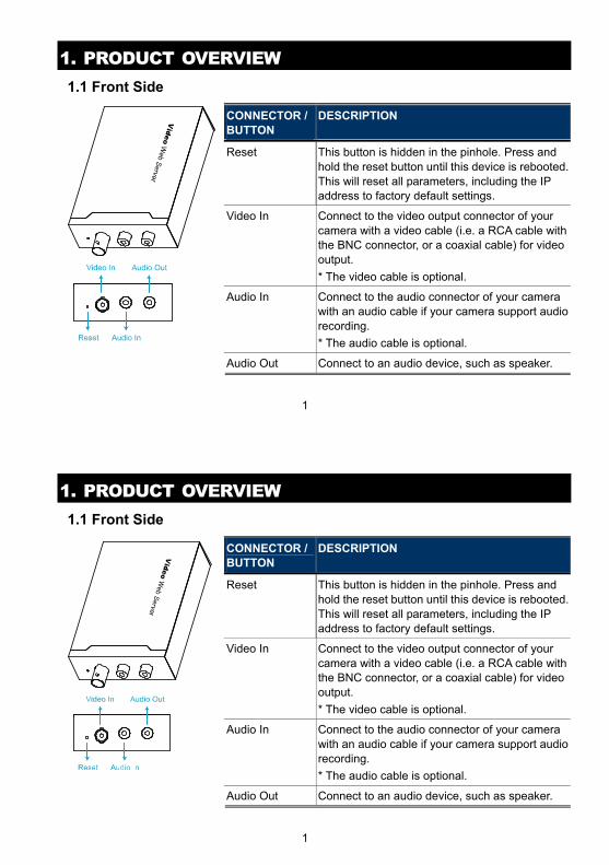
1. PRODUCT OVERVIEW 1.1 Front Side
CONNECTOR / BUTTON
DESCRIPTION
Reset This button is hidden in the pinhole. Press and hold the reset button until this device is rebooted. This will reset all parameters, including the IP address to factory default settings.
Video In Connect to the video output connector of your camera with a video cable (i.e. a RCA cable with the BNC connector, or a coaxial cable) for video output.
* The video cable is optional.
Audio In Connect to the audio connector of your camera with an audio cable if your camera support audio recording.
* The audio cable is optional.
Audio Out Connect to an audio device, such as speaker.
1
1. PRODUCT OVERVIEW 1.1 Front Side
CONNECTOR / BUTTON
DESCRIPTION
Reset This button is hidden in the pinhole. Press and hold the reset button until this device is rebooted. This will reset all parameters, including the IP address to factory default settings.
Video In Connect to the video output connector of your camera with a video cable (i.e. a RCA cable with the BNC connector, or a coaxial cable) for video output.
* The video cable is optional.
Audio In Connect to the audio connector of your camera with an audio cable if your camera support audio recording.
* The audio cable is optional.
Audio Out Connect to an audio device, such as speaker.
2
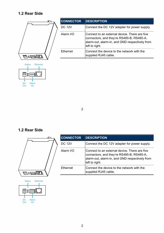
1.2 Rear Side
CONNECTOR DESCRIPTION
DC 12V Connect the DC 12V adapter for power supply.
Alarm I/O Connect to an external device. There are five connectors, and they’re RS485-B, RS485-A, alarm-out, alarm-in, and GND respectively from left to right.
Ethernet Connect the device to the network with the supplied RJ45 cable.
DC12V
AlarmI/O
Status Ethernet
2
1.2 Rear Side
CONNECTOR DESCRIPTION
DC 12V Connect the DC 12V adapter for power supply.
Alarm I/O Connect to an external device. There are five connectors, and they’re RS485-B, RS485-A, alarm-out, alarm-in, and GND respectively from left to right.
Ethernet Connect the device to the network with the supplied RJ45 cable.
DC12V
AlarmI/O
Status Ethernet
3
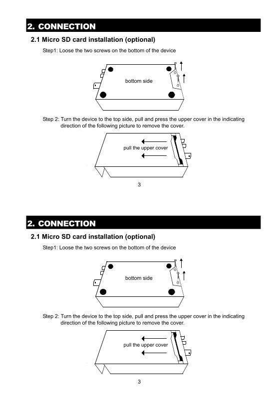
2. CONNECTION 2.1 Micro SD card installation (optional)
Step1: Loose the two screws on the bottom of the device
bottom side
Step 2: Turn the device to the top side, pull and press the upper cover in the indicating
direction of the following picture to remove the cover.
pull the upper cover
3
2. CONNECTION 2.1 Micro SD card installation (optional)
Step1: Loose the two screws on the bottom of the device
bottom side
Step 2: Turn the device to the top side, pull and press the upper cover in the indicating
direction of the following picture to remove the cover.
pull the upper cover
4
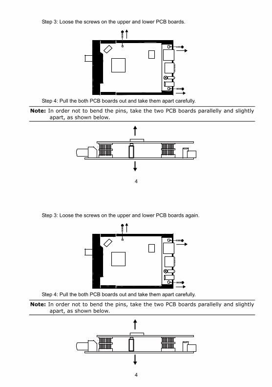
Step 3: Loose the screws on the upper and lower PCB boards.
Step 4: Pull the both PCB boards out and take them apart carefully.
Note: In order not to bend the pins, take the two PCB boards parallelly and slightly apart, as shown below.
4
Step 3: Loose the screws on the upper and lower PCB boards again.
Step 4: Pull the both PCB boards out and take them apart carefully.
Note: In order not to bend the pins, take the two PCB boards parallelly and slightly apart, as shown below.
5
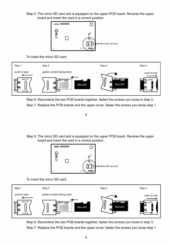
Step 5: The micro SD card slot is equipped on the upper PCB board. Reverse the upper board and insert the card in a correct position.
Micro SD card slot
To insert the micro SD card:
push to open
Step 1
open
lock
Step 3
push to lock
Step 4
golden contact facing down
Step 2
Step 6: Recombine the two PCB boards together, fasten the screws you loose in step 3.
Step 7: Replace the PCB boards and the upper cover, fasten the screws you loose step 1
5
Step 5: The micro SD card slot is equipped on the upper PCB board. Reverse the upper board and insert the card in a correct position.
Micro SD card slot
To insert the micro SD card:
push to open
Step 1
open
lock
Step 3
push to lock
Step 4
golden contact facing down
Step 2
Step 6: Recombine the two PCB boards together, fasten the screws you loose in step 3.
Step 7: Replace the PCB boards and the upper cover, fasten the screws you loose step 1
6
2.2 Connect the device to the Camera
Step1: Finish camera installation as described in its respective user manual.
Step2: Connect the video ouput of the camera to the video input of this device with a video cable.
Note: The video cable is not supplied within the sales package. Please purchase separately.
Step3: (Optional) Connect the audio output of the camera to the audio input of this device with an audio cable if your camera support audio recording.
Note: The audio cable is not supplied within the sales package. Please purchase separately.
Step4: Connect the camera to power.
Note: The camera adapter might be supplied with the camera. Please check your camera’s sales package. If not, please use the regulated adapter with correct output voltage.
Step5: Connect this device to power with the supplied adapter.
Step6: Connect this device to Internet. For details, please refer to the next chapter, “3. CAMERA ACCESS AND NETWORK CONFIGURATION”.
7
3. CAMERA ACCESS AND NETWORK CONFIGURATION Before using this network camera, please follow the instructions below to finish the network connection settings based on your installation environment:
To configure the network settings, you must connect the camera to your PC by LAN. For details, please refer to “3.1 Network connection via LAN” at page 7.
To configure the network settings via a web browser, please refer to “3.2 Camera access via web browser” at page 11.
3.1 Network connection via LAN
Step1: Connect this network camera and your PC via a RJ45 network cable, and make sure the camera is powered on.
Step2: Set the PC’s IP address as “192.168.1.XXX” (1~255, except 10).
8
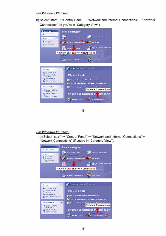
For Windows XP users:
b) Select “start” “Control Panel” “Network and Internet Connections” “Network
Connections” (If you’re in “Category View”).
8
For Windows XP users:
a) Select “start” “Control Panel” “Network and Internet Connections” “Network Connections” (If you’re in “Category View”).
9
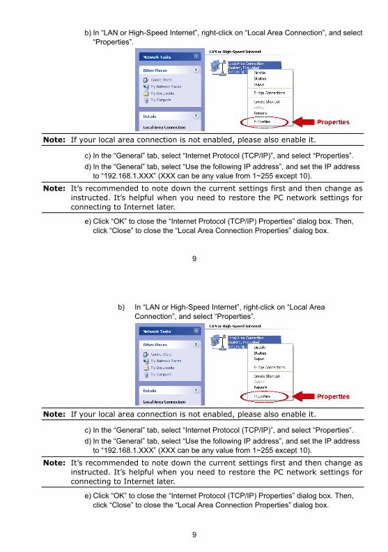
b) In “LAN or High-Speed Internet”, right-click on “Local Area Connection”, and select “Properties”.
Note: If your local area connection is not enabled, please also enable it.
c) In the “General” tab, select “Internet Protocol (TCP/IP)”, and select “Properties”.
d) In the “General” tab, select “Use the following IP address”, and set the IP address to “192.168.1.XXX” (XXX can be any value from 1~255 except 10).
Note: It’s recommended to note down the current settings first and then change as instructed. It’s helpful when you need to restore the PC network settings for connecting to Internet later.
e) Click “OK” to close the “Internet Protocol (TCP/IP) Properties” dialog box. Then, click “Close” to close the “Local Area Connection Properties” dialog box.
9
b) In “LAN or High-Speed Internet”, right-click on “Local Area Connection”, and select “Properties”.
Note: If your local area connection is not enabled, please also enable it.
c) In the “General” tab, select “Internet Protocol (TCP/IP)”, and select “Properties”.
d) In the “General” tab, select “Use the following IP address”, and set the IP address to “192.168.1.XXX” (XXX can be any value from 1~255 except 10).
Note: It’s recommended to note down the current settings first and then change as instructed. It’s helpful when you need to restore the PC network settings for connecting to Internet later.
e) Click “OK” to close the “Internet Protocol (TCP/IP) Properties” dialog box. Then, click “Close” to close the “Local Area Connection Properties” dialog box.
10
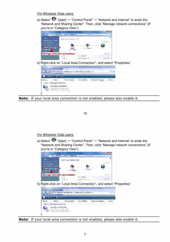
For Windows Vista users:
a) Select “ ” (start) “Control Panel” “Network and Internet” to enter the “Network and Sharing Center”. Then, click “Manage network connections” (If you’re in “Category View”).
b) Right-click on “Local Area Connection”, and select “Properties”.
Note: If your local area connection is not enabled, please also enable it.
7
For Windows Vista users:
a) Select “ ” (start) “Control Panel” “Network and Internet” to enter the “Network and Sharing Center”. Then, click “Manage network connections” (If you’re in “Category View”).
b) Right-click on “Local Area Connection”, and select “Properties”.
Note: If your local area connection is not enabled, please also enable it.
8
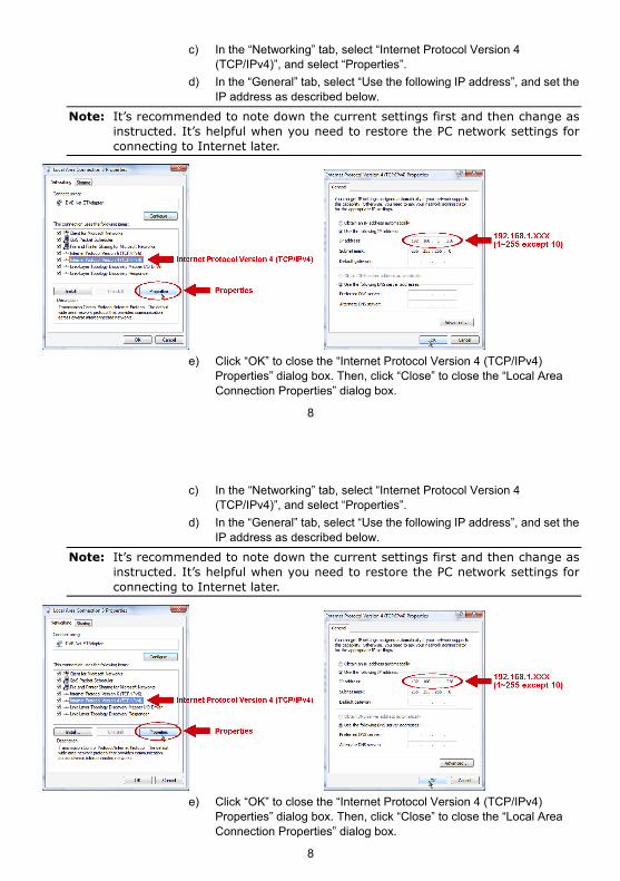
c) In the “Networking” tab, select “Internet Protocol Version 4 (TCP/IPv4)”, and select “Properties”.
d) In the “General” tab, select “Use the following IP address”, and set the IP address as described below.
Note: It’s recommended to note down the current settings first and then change as instructed. It’s helpful when you need to restore the PC network settings for connecting to Internet later.
e) Click “OK” to close the “Internet Protocol Version 4 (TCP/IPv4)
Properties” dialog box. Then, click “Close” to close the “Local Area Connection Properties” dialog box.
8
c) In the “Networking” tab, select “Internet Protocol Version 4 (TCP/IPv4)”, and select “Properties”.
d) In the “General” tab, select “Use the following IP address”, and set the IP address as described below.
Note: It’s recommended to note down the current settings first and then change as instructed. It’s helpful when you need to restore the PC network settings for connecting to Internet later.
e) Click “OK” to close the “Internet Protocol Version 4 (TCP/IPv4)
Properties” dialog box. Then, click “Close” to close the “Local Area Connection Properties” dialog box.
9
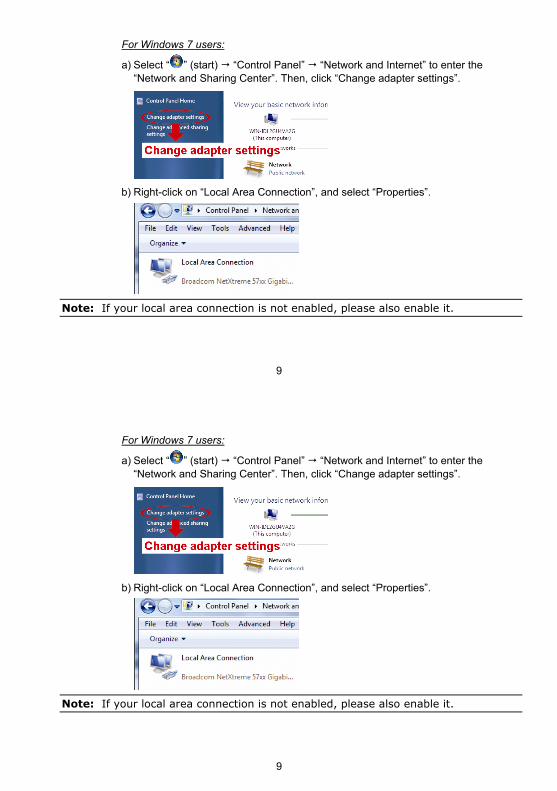
For Windows 7 users:
a) Select “ ” (start) “Control Panel” “Network and Internet” to enter the “Network and Sharing Center”. Then, click “Change adapter settings”.
b) Right-click on “Local Area Connection”, and select “Properties”.
Note: If your local area connection is not enabled, please also enable it.
9
For Windows 7 users:
a) Select “ ” (start) “Control Panel” “Network and Internet” to enter the “Network and Sharing Center”. Then, click “Change adapter settings”.
b) Right-click on “Local Area Connection”, and select “Properties”.
Note: If your local area connection is not enabled, please also enable it.
10
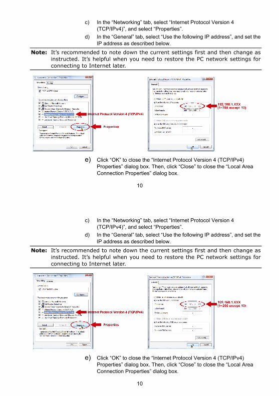
c) In the “Networking” tab, select “Internet Protocol Version 4 (TCP/IPv4)”, and select “Properties”.
d) In the “General” tab, select “Use the following IP address”, and set the IP address as described below.
Note: It’s recommended to note down the current settings first and then change as instructed. It’s helpful when you need to restore the PC network settings for connecting to Internet later.
e) Click “OK” to close the “Internet Protocol Version 4 (TCP/IPv4) Properties” dialog box. Then, click “Close” to close the “Local Area Connection Properties” dialog box.
10
c) In the “Networking” tab, select “Internet Protocol Version 4 (TCP/IPv4)”, and select “Properties”.
d) In the “General” tab, select “Use the following IP address”, and set the IP address as described below.
Note: It’s recommended to note down the current settings first and then change as instructed. It’s helpful when you need to restore the PC network settings for connecting to Internet later.
e) Click “OK” to close the “Internet Protocol Version 4 (TCP/IPv4) Properties” dialog box. Then, click “Close” to close the “Local Area Connection Properties” dialog box.
11
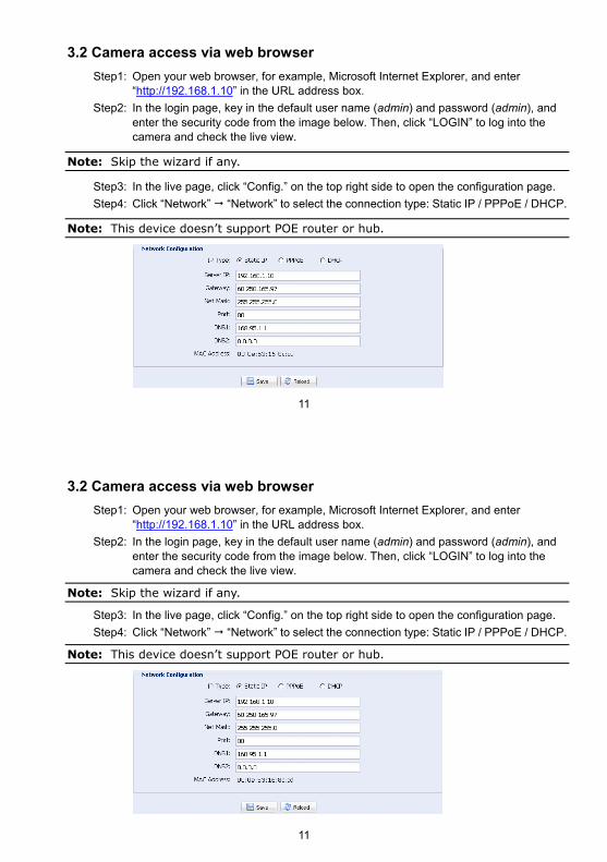
3.2 Camera access via web browser
Step1: Open your web browser, for example, Microsoft Internet Explorer, and enter “http://192.168.1.10” in the URL address box.
Step2: In the login page, key in the default user name (admin) and password (admin), and enter the security code from the image below. Then, click “LOGIN” to log into the camera and check the live view.
Note: Skip the wizard if any.
Step3: In the live page, click “Config.” on the top right side to open the configuration page.
Step4: Click “Network” “Network” to select the connection type: Static IP / PPPoE / DHCP.
Note: This device doesn’t support POE router or hub.
11
3.2 Camera access via web browser
Step1: Open your web browser, for example, Microsoft Internet Explorer, and enter “http://192.168.1.10” in the URL address box.
Step2: In the login page, key in the default user name (admin) and password (admin), and enter the security code from the image below. Then, click “LOGIN” to log into the camera and check the live view.
Note: Skip the wizard if any.
Step3: In the live page, click “Config.” on the top right side to open the configuration page.
Step4: Click “Network” “Network” to select the connection type: Static IP / PPPoE / DHCP.
Note: This device doesn’t support POE router or hub.
12
For Static IP:
a) Enter the information of “Server IP”, “Gateway” and “Net Mask” obtained from your ISP (Internet Service Provider).
b) Enter the port number. The valid number ranges from 1 to 9999. The default value is 80. Typically, the TCP port used by HTTP is 80. However in some cases, it is better to change this port number for added flexibility or security.
c) Click “Save” to save your network configurations, and log out.
d) Disconnect your device and your PC, and connect them to Internet separately. Then, enter the IP address or host name you just note down in the URL address box of the web browser, and see if you can access the device successfully.
For PPPOE:
a) Enter the user name and password obtained from your ISP, and click “Save”.
b) Continue the DDNS setting as instructed in “3.2.1 DDNS Setting”.
For DHCP:
a) Before selecting this option, you need to finish the DHCP router settings first.
b) Get a router and connect it to the Internet via your PC (with Static IP or PPPoE setting). There are different setting methods for different routers. Please refer to their respective user manuals.
c) Continue the DDNS setting as instructed in “3.2.1 DDNS Setting”.
13
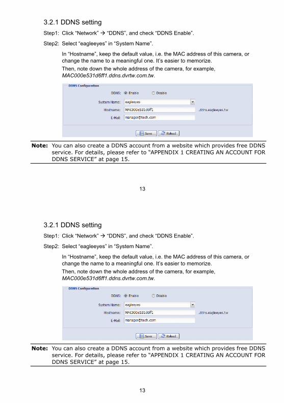
3.2.1 DDNS setting
Step1: Click “Network” “DDNS”, and check “DDNS Enable”.
Step2: Select “eagleeyes” in “System Name”.
In “Hostname”, keep the default value, i.e. the MAC address of this camera, or change the name to a meaningful one. It’s easier to memorize.
Then, note down the whole address of the camera, for example, MAC000e531d6ff1.ddns.dvrtw.com.tw.
Note: You can also create a DDNS account from a website which provides free DDNS service. For details, please refer to “APPENDIX 1 CREATING AN ACCOUNT FOR DDNS SERVICE” at page 15.
13
3.2.1 DDNS setting
Step1: Click “Network” “DDNS”, and check “DDNS Enable”.
Step2: Select “eagleeyes” in “System Name”.
In “Hostname”, keep the default value, i.e. the MAC address of this camera, or change the name to a meaningful one. It’s easier to memorize.
Then, note down the whole address of the camera, for example, MAC000e531d6ff1.ddns.dvrtw.com.tw.
Note: You can also create a DDNS account from a website which provides free DDNS service. For details, please refer to “APPENDIX 1 CREATING AN ACCOUNT FOR DDNS SERVICE” at page 15.
14
Step3: Click “Save” and log out. Then, disconnect your device and your PC, and connect them to Internet separately.
Step4: Enter the host name you just note down in the URL address box of the web browser, and see if you can access the device successfully.
14
Step3: Click “Save” and log out. Then, disconnect your device and your PC, and connect them to Internet separately.
Step4: Enter the host name you just note down in the URL address box of the web browser, and see if you can access the device successfully.
15
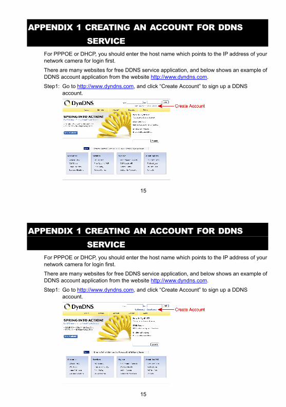
APPENDIX 1 CREATING AN ACCOUNT FOR DDNS SERVICE
For PPPOE or DHCP, you should enter the host name which points to the IP address of your network camera for login first.
There are many websites for free DDNS service application, and below shows an example of DDNS account application from the website http://www.dyndns.com.
Step1: Go to http://www.dyndns.com, and click “Create Account” to sign up a DDNS account.
15
APPENDIX 1 CREATING AN ACCOUNT FOR DDNS SERVICE
For PPPOE or DHCP, you should enter the host name which points to the IP address of your network camera for login first.
There are many websites for free DDNS service application, and below shows an example of DDNS account application from the website http://www.dyndns.com.
Step1: Go to http://www.dyndns.com, and click “Create Account” to sign up a DDNS account.
16
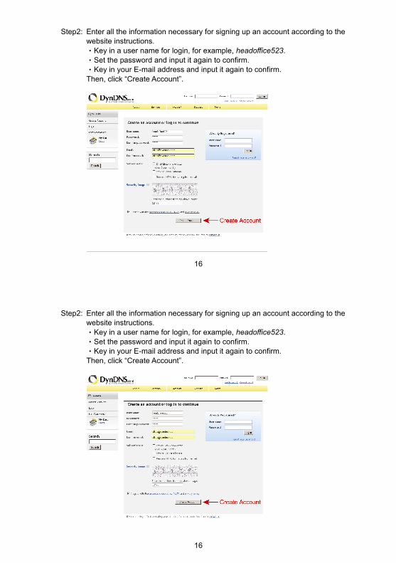
Step2: Enter all the information necessary for signing up an account according to the website instructions. ‧Key in a user name for login, for example, headoffice523. ‧Set the password and input it again to confirm. ‧Key in your E-mail address and input it again to confirm. Then, click “Create Account”.
16
Step2: Enter all the information necessary for signing up an account according to the website instructions. ‧Key in a user name for login, for example, headoffice523. ‧Set the password and input it again to confirm. ‧Key in your E-mail address and input it again to confirm. Then, click “Create Account”.
17
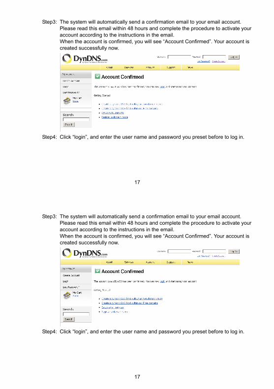
Step3: The system will automatically send a confirmation email to your email account. Please read this email within 48 hours and complete the procedure to activate your account according to the instructions in the email. When the account is confirmed, you will see “Account Confirmed”. Your account is created successfully now.
Step4: Click “login”, and enter the user name and password you preset before to log in.
17
Step3: The system will automatically send a confirmation email to your email account. Please read this email within 48 hours and complete the procedure to activate your account according to the instructions in the email. When the account is confirmed, you will see “Account Confirmed”. Your account is created successfully now.
Step4: Click “login”, and enter the user name and password you preset before to log in.
18
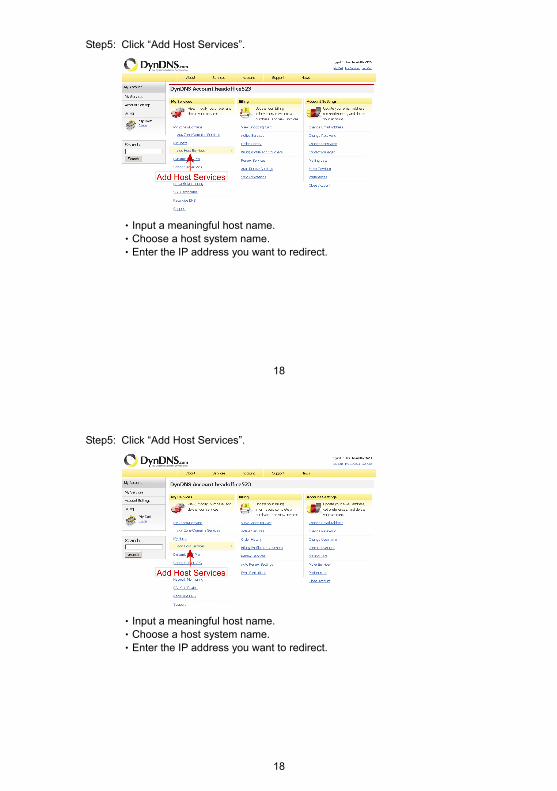
Step5: Click “Add Host Services”.
‧Input a meaningful host name. ‧Choose a host system name. ‧Enter the IP address you want to redirect.
18
Step5: Click “Add Host Services”.
‧Input a meaningful host name. ‧Choose a host system name. ‧Enter the IP address you want to redirect.
19
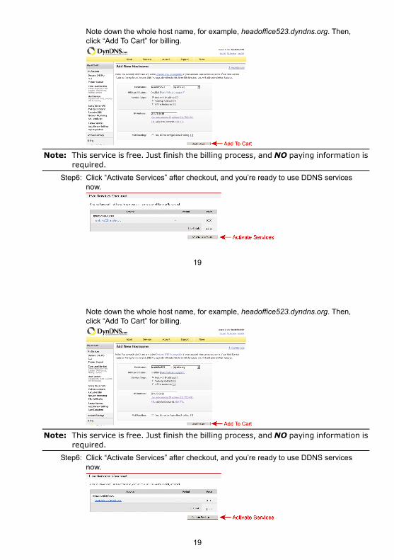
Note down the whole host name, for example, headoffice523.dyndns.org. Then, click “Add To Cart” for billing.
Note: This service is free. Just finish the billing process, and NO paying information is
required. Step6: Click “Activate Services” after checkout, and you’re ready to use DDNS services
now.
19
Note down the whole host name, for example, headoffice523.dyndns.org. Then, click “Add To Cart” for billing.
Note: This service is free. Just finish the billing process, and NO paying information is
required. Step6: Click “Activate Services” after checkout, and you’re ready to use DDNS services
now.
20
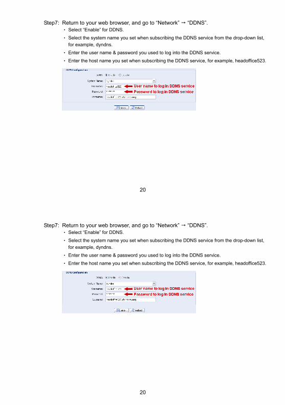
Step7: Return to your web browser, and go to “Network” “DDNS”. ‧ Select “Enable” for DDNS.
‧ Select the system name you set when subscribing the DDNS service from the drop-down list,
for example, dyndns.
‧ Enter the user name & password you used to log into the DDNS service.
‧ Enter the host name you set when subscribing the DDNS service, for example, headoffice523.
20
Step7: Return to your web browser, and go to “Network” “DDNS”. ‧ Select “Enable” for DDNS.
‧ Select the system name you set when subscribing the DDNS service from the drop-down list,
for example, dyndns.
‧ Enter the user name & password you used to log into the DDNS service.
‧ Enter the host name you set when subscribing the DDNS service, for example, headoffice523.