Embed Size (px)
Citation preview
To prevent electrical shock and/or equipment damage, disconnect electric power to system at main fuse or circuit breaker box until installation is complete.
CAUTION! ATTENTION: MERCURY NOTICEThis product does not contain mercury. However, this product may replace a product that contains mercury.
Mercury and products containing mercury must not be discarded in household trash. Do not touch any spilled mercury. Wearing non-absorbent gloves, clean up any spilled mercury and place in a sealed container. For proper disposal of a product containing mercury or a sealed container of spilled mercury, place it in a suitable shipping container. Refer to www.thermostat-recycle.org for location to send product containing mercury.
Index PageInstallation 2Wiring Connections 2Wiring Diagrams 3Thermostat Quick Reference 4Installer Configuration Menu 5Operating Your Thermostat 7Troubleshooting 8
Model Programming Choices
1F95EZ-0671 Non-Programmable 7 Day
Blue Easy Reader Thermostat
www.white-rodgers.comwww.emersonclimate.com
PART NO. 37-6986CReplaces 37-6986B
1407
Single Stage, Multi-Stage, Heat PumpInstallation Instructions for Model:
APPLICATIONS THERMOSTAT APPLICATION GUIDE
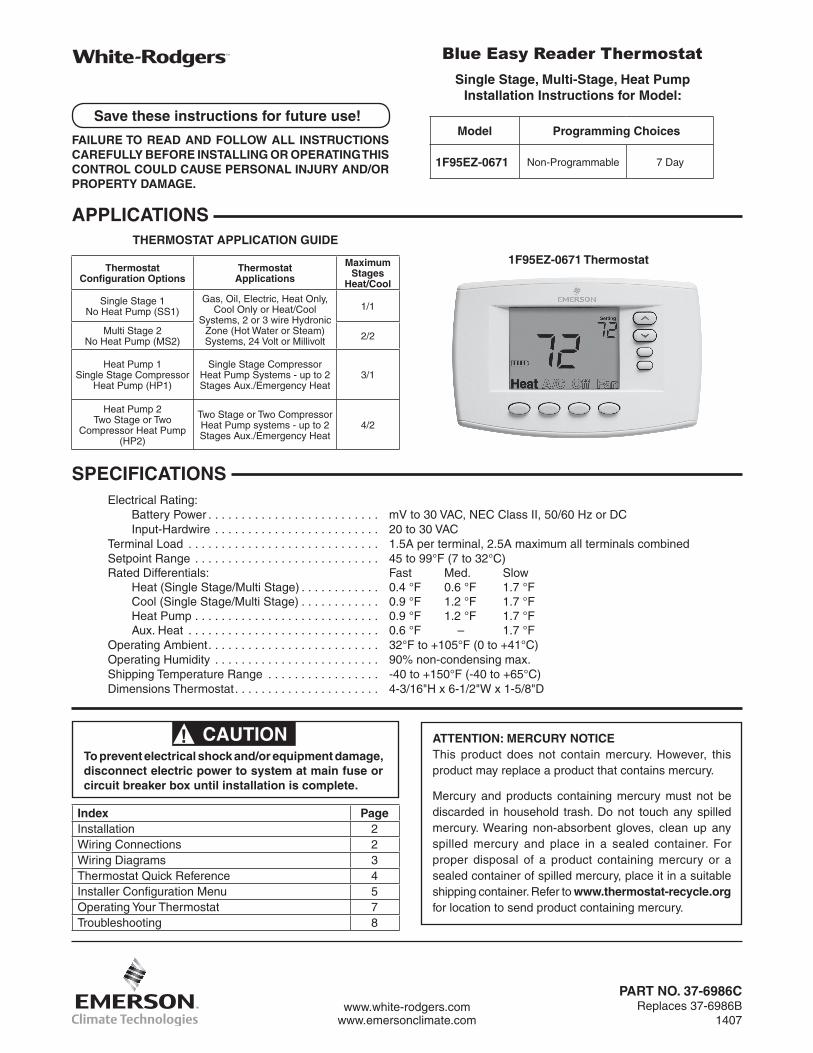
1F95EZ-0671 Thermostat
SPECIFICATIONS
Save these instructions for future use!
FAILURE TO READ AND FOLLOW ALL INSTRUCTIONS CAREFULLY BEFORE INSTALLING OR OPERATING THIS CONTROL COULD CAUSE PERSONAL INJURY AND/OR PROPERTY DAMAGE.
Electrical Rating: Battery Power . . . . . . . . . . . . . . . . . . . . . . . . . . mV to 30 VAC, NEC Class II, 50/60 Hz or DC Input-Hardwire . . . . . . . . . . . . . . . . . . . . . . . . . 20 to 30 VACTerminal Load . . . . . . . . . . . . . . . . . . . . . . . . . . . . . 1.5A per terminal, 2.5A maximum all terminals combinedSetpoint Range . . . . . . . . . . . . . . . . . . . . . . . . . . . . 45 to 99°F (7 to 32°C)Rated Differentials: Fast Med. Slow Heat (Single Stage/Multi Stage) . . . . . . . . . . . . 0.4 °F 0.6 °F 1.7 °F Cool (Single Stage/Multi Stage) . . . . . . . . . . . . 0.9 °F 1.2 °F 1.7 °F Heat Pump . . . . . . . . . . . . . . . . . . . . . . . . . . . . 0.9 °F 1.2 °F 1.7 °F Aux. Heat . . . . . . . . . . . . . . . . . . . . . . . . . . . . . 0.6 °F – 1.7 °FOperating Ambient. . . . . . . . . . . . . . . . . . . . . . . . . . 32°F to +105°F (0 to +41°C)Operating Humidity . . . . . . . . . . . . . . . . . . . . . . . . . 90% non-condensing max.Shipping Temperature Range . . . . . . . . . . . . . . . . . -40 to +150°F (-40 to +65°C)Dimensions Thermostat. . . . . . . . . . . . . . . . . . . . . . 4-3/16"H x 6-1/2"W x 1-5/8"D
Thermostat Configuration Options
Thermostat Applications
Maximum Stages
Heat/Cool
Single Stage 1No Heat Pump (SS1)
Gas, Oil, Electric, Heat Only, Cool Only or Heat/Cool
Systems, 2 or 3 wire Hydronic Zone (Hot Water or Steam) Systems, 24 Volt or Millivolt
1/1
Multi Stage 2No Heat Pump (MS2) 2/2
Heat Pump 1Single Stage Compressor
Heat Pump (HP1)
Single Stage Compressor Heat Pump Systems - up to 2 Stages Aux./Emergency Heat
3/1
Heat Pump 2Two Stage or Two
Compressor Heat Pump (HP2)
Two Stage or Two Compressor Heat Pump systems - up to 2 Stages Aux./Emergency Heat
4/2
2
Remove Old ThermostatBefore removing wires from old thermostat, mark wires for terminal identification so the proper connections will be made to the new thermostat.
Installing New Thermostat1. Pull the thermostat body off the thermostat base. Forcing or prying on the thermostat will cause damage to the unit.2. Place base over hole in wall and mark mounting hole locations on wall using base as a template.3. Move base out of the way. Drill mounting holes. If you are using existing mounting holes and the holes drilled are too large and do not allow you to tighten base snugly,
use plastic screw anchors to secure the base.4. Fasten base snugly to wall using mounting holes shown in Figure 1 and two mounting screws. Leveling is for appearance only and will not affect thermostat operation.5. Connect wires to terminal block on base using appropriate
wiring schematic.6. Push excess wire into wall and plug hole with a fire
resistant material (such as fiberglass insulation) to prevent drafts from affecting thermostat operation.7. Install 2 "AA" alkaline batteries.8. Carefully line the thermostat up with the base and snap into place.
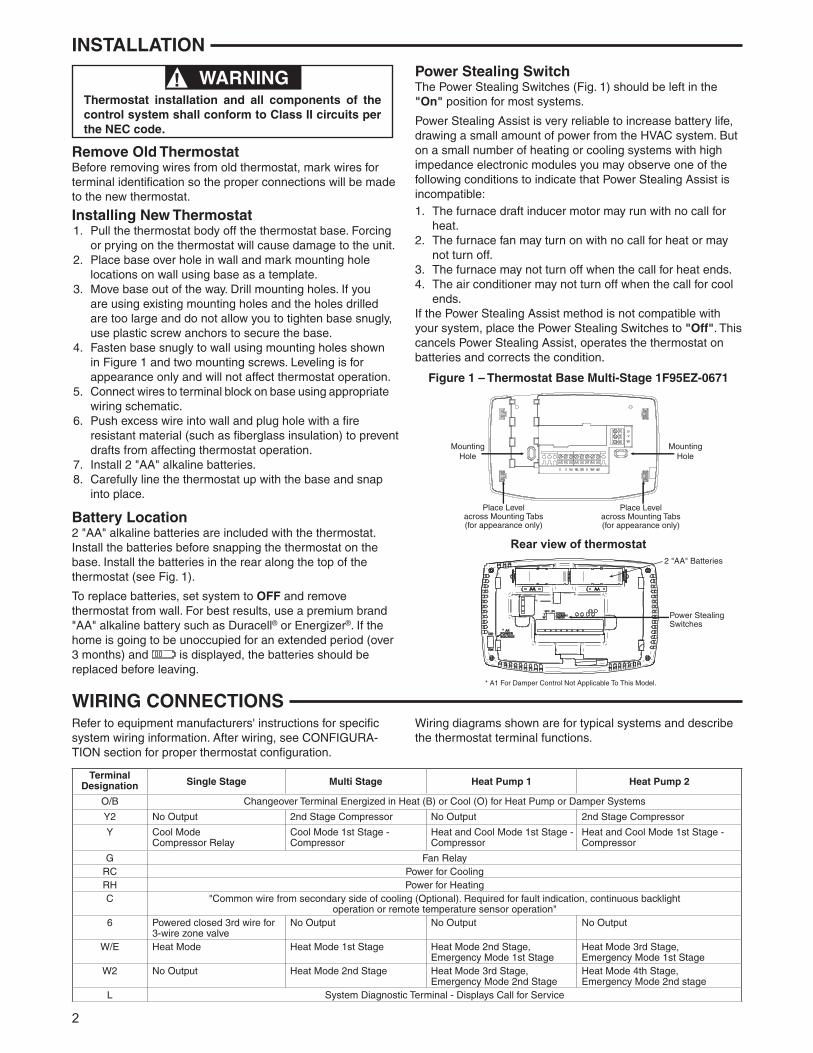
Battery Location2 "AA" alkaline batteries are included with the thermostat. Install the batteries before snapping the thermostat on the base. Install the batteries in the rear along the top of the thermostat (see Fig. 1).
To replace batteries, set system to OFF and remove thermostat from wall. For best results, use a premium brand "AA" alkaline battery such as Duracell® or Energizer®. If the home is going to be unoccupied for an extended period (over 3 months) and is displayed, the batteries should be replaced before leaving.
WIRING CONNECTIONS Refer to equipment manufacturers' instructions for specific system wiring information. After wiring, see CONFIGURA-TION section for proper thermostat configuration.
Wiring diagrams shown are for typical systems and describe the thermostat terminal functions.
WARNING!Thermostat installation and all components of the control system shall conform to Class II circuits per the NEC code.
INSTALLATION
Figure 1 – Thermostat Base Multi-Stage 1F95EZ-0671
Rear view of thermostat2 "AA" Batteries
Power Stealing Switches
*
* A1 For Damper Control Not Applicable To This Model.
Place Levelacross Mounting Tabs(for appearance only)
MountingHole
MountingHole
Place Levelacross Mounting Tabs(for appearance only)
Power Stealing SwitchThe Power Stealing Switches (Fig. 1) should be left in the "On" position for most systems.
Power Stealing Assist is very reliable to increase battery life, drawing a small amount of power from the HVAC system. But on a small number of heating or cooling systems with high impedance electronic modules you may observe one of the following conditions to indicate that Power Stealing Assist is incompatible: 1. The furnace draft inducer motor may run with no call for
heat.2. The furnace fan may turn on with no call for heat or may
not turn off.3. The furnace may not turn off when the call for heat ends.4. The air conditioner may not turn off when the call for cool
ends.If the Power Stealing Assist method is not compatible with your system, place the Power Stealing Switches to "Off". This cancels Power Stealing Assist, operates the thermostat on batteries and corrects the condition.
Terminal Designation Single Stage Multi Stage Heat Pump 1 Heat Pump 2
O/B Changeover Terminal Energized in Heat (B) or Cool (O) for Heat Pump or Damper Systems
Y2 No Output 2nd Stage Compressor No Output 2nd Stage Compressor
Y Cool Mode Compressor Relay
Cool Mode 1st Stage - Compressor
Heat and Cool Mode 1st Stage - Compressor
Heat and Cool Mode 1st Stage - Compressor
G Fan RelayRC Power for CoolingRH Power for HeatingC "Common wire from secondary side of cooling (Optional). Required for fault indication, continuous backlight
operation or remote temperature sensor operation"6 Powered closed 3rd wire for
3-wire zone valveNo Output No Output No Output
W/E Heat Mode Heat Mode 1st Stage Heat Mode 2nd Stage, Emergency Mode 1st Stage
Heat Mode 3rd Stage, Emergency Mode 1st Stage
W2 No Output Heat Mode 2nd Stage Heat Mode 3rd Stage, Emergency Mode 2nd Stage
Heat Mode 4th Stage, Emergency Mode 2nd stage
L System Diagnostic Terminal - Displays Call for Service
3
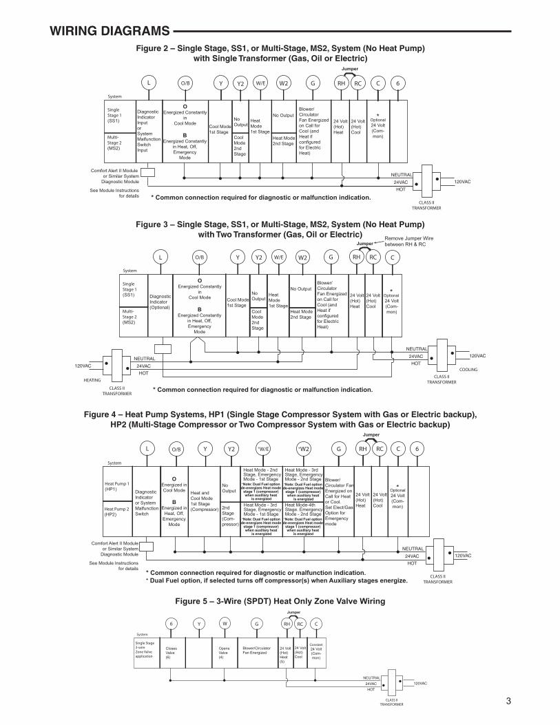
WIRING DIAGRAMS Figure 2 – Single Stage, SS1, or Multi-Stage, MS2, System (No Heat Pump)
with Single Transformer (Gas, Oil or Electric)
SingleStage 1(SS1)
Multi-Stage 2(MS2)
OEnergized Constantly
inCool Mode
BEnergized Constantly
in Heat, Off,Emergency
Mode
NoOutput
CoolMode2ndStage
Cool Mode1st Stage
Blower/CirculatorFan Energizedon Call forCool (andHeat ifconfiguredfor ElectricHeat)
No Output
Heat Mode2nd Stage
HeatMode1st Stage
Optional24 Volt(Com-mon)
24 Volt(Hot)Cool
System
Y GW/E C 6L RC
CLASS IITRANSFORMER
HOT
24VAC
NEUTRAL
120VAC
24 Volt(Hot)Heat
RHY2 W2
Jumper
DiagnosticIndicator InputorSystemMalfunctionSwitch Input
Comfort Alert II Module or Similar System
Diagnostic Module
See Module Instructionsfor details
O/B
*
* Common connection required for diagnostic or malfunction indication.
Single Stage3-wireZone Valveapplication
Blower/CirculatorFan Energized
OpensValve(4)
Constant24 Volt(Com-mon)
24 Volt(Hot)Cool
System
6 Y W CRC
CLASS IITRANSFORMER
HOT
24VAC
NEUTRAL
120VAC
24 Volt(Hot)Heat(5)
RHG
Jumper
ClosesValve(6)
Figure 5 – 3-Wire (SPDT) Heat Only Zone Valve Wiring
Figure 3 – Single Stage, SS1, or Multi-Stage, MS2, System (No Heat Pump) with Two Transformer (Gas, Oil or Electric)
SingleStage 1(SS1)
Multi-Stage 2(MS2)
NoOutput
CoolMode2ndStage
Cool Mode1st Stage
Blower/CirculatorFan Energizedon Call forCool (andHeat ifconfiguredfor ElectricHeat)
No Output
Heat Mode2nd Stage
HeatMode1st Stage
Optional 24 Volt(Com-mon)
DiagnosticIndicator(Optional)
24 Volt(Hot)Cool
System
Y GW/E CL RC
CLASS IITRANSFORMER
HOT
24VAC
NEUTRAL
120VAC
24 Volt(Hot)Heat
RH
120VAC
Remove Jumper Wirebetween RH & RC
HOT
24VAC
NEUTRAL
CLASS IITRANSFORMER
HEATING
COOLING
Y2 W2
Jumper
O/B
OEnergized Constantly
inCool Mode
BEnergized Constantly
in Heat, Off,Emergency
Mode
*
* Common connection required for diagnostic or malfunction indication.
Figure 4 – Heat Pump Systems, HP1 (Single Stage Compressor System with Gas or Electric backup), HP2 (Multi-Stage Compressor or Two Compressor System with Gas or Electric backup)
Heat Pump 1(HP1)
Heat Pump 2(HP2)
OEnergized inCool Mode
BEnergized in
Heat, Off,Emergency
Mode
NoOutput
2ndStage(Com-pressor)
Heat andCool Mode1st Stage(Compressor)
Blower/Circulator FanEnergized onCall for Heator Cool.Set Elect/GasOption forEmergencymode
Heat Mode - 3rdStage, Emergency Mode - 2nd Stage
Heat Mode-4thStage. EmergencyMode - 2nd Stage
Heat Mode - 2ndStage, EmergencyMode - 1st Stage
Heat Mode - 3rd Stage, EmergencyMode - 1st Stage
Optional24 Volt(Com-mon)
Diagnostic Indicator or SystemMalfunctionSwitch
24 Volt(Hot)Cool
System
Y +W/E CL 6RC
CLASS IITRANSFORMER
HOT
24VAC
NEUTRAL
120VAC
24 Volt(Hot)Heat
RH
Jumper
Y2 +W2 G
Comfort Alert II Moduleor Similar System
Diagnostic Module
See Module Instructionsfor details
O/B
+Note: Dual Fuel option de-energizes Heat mode
stage 1 (compressor) when auxiliary heat
is energized
+Note: Dual Fuel option de-energizes Heat mode
stage 1 (compressor) when auxiliary heat
is energized
+Note: Dual Fuel option de-energizes Heat mode
stage 1 (compressor) when auxiliary heat
is energized
+Note: Dual Fuel option de-energizes Heat mode
stage 1 (compressor) when auxiliary heat
is energized
*
* Common connection required for diagnostic or malfunction indication.+ Dual Fuel option, if selected turns off compressor(s) when Auxiliary stages energize.
4
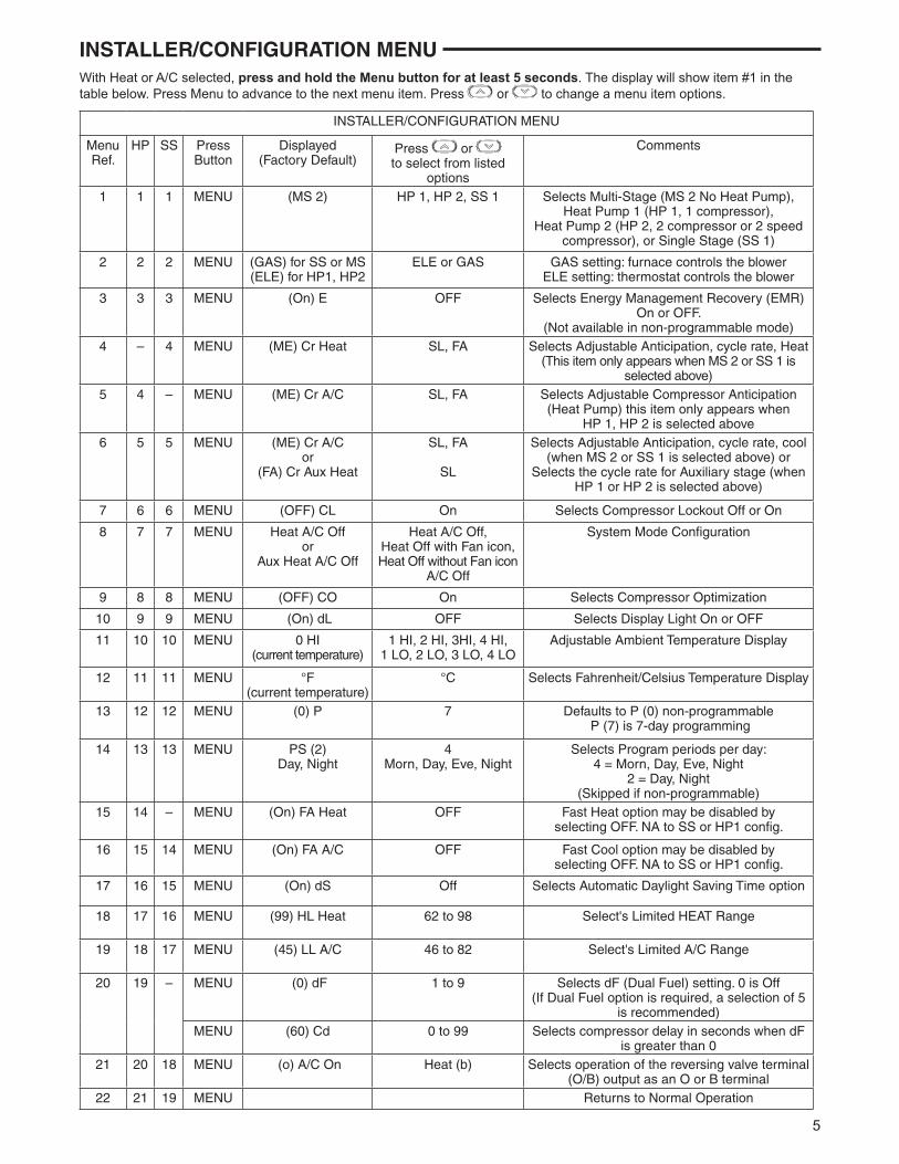
Programming and Configuration Items
1 “Heat" “A/C” “Off” identifies button. When filled indi-cates system mode selected.
2 " " indicates thermostat configured for Heat Pump. "Aux" indicates Auxiliary (Emergency) stage is selected.
3 "Adv Day" identifies button when in schedule mode.4 "Time" identifies button when in schedule mode.5 "Fan" identifies button. When filled indicates Fan is on.6 "Run" identifies button to begin normal operation.7 "Sched" identifies button to be used during program-
ming or "Run Sched" identifies button to return to normal operation.
8 "Hold" "Copy" "Menu" identifies button.9 "Limit" indicates temperature is adjusted to the limit set
in the configuration menu.
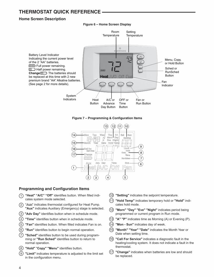
THERMOSTAT QUICK REFERENCE Home Screen Description
Figure 6 – Home Screen Display
Figure 7 – Programming & Configuration Items
10 "Setting" indicates the setpoint temperature.11 "Hold Temp" indicates temporary hold or "Hold" indi-
cates hold mode.12 "Morn" "Day" "Eve" "Night" indicates period being
programmed or current program in Run mode.13 "A" "P" indicates time as Morning (A) or Evening (P).14 "Mon - Sun" indicates day of week.15 "Month" "Year" "Date" indicates the Month Year or
Date when setting time.16 "Call For Service" indicates a diagnostic fault in the
heating/cooling system. It does not indicate a fault in the thermostat.
17 "Change" indicates when batteries are low and should be replaced.
7
6
4
1
3
17
16
15
13 12 10
8
9
2 5
14
11
RoomTemperature
SettingTemperature
SystemIndicators
FanIndicator
Sched or RunSchedButton
Menu, Copy, or Hold Button
HeatButton
A/C or Advance
Day Button
OFF orTime Button
Fan or Run Button
Battery Level IndicatorIndicating the current power levelof the 2 “AA” batteries. Full power remaining. Half power remaining.Change The batteries shouldbe replaced at this time with 2 new premium brand “AA” Alkaline batteries.(See page 2 for more details).
5
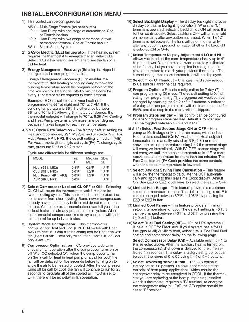
INSTALLER/CONFIGURATION MENU With Heat or A/C selected, press and hold the Menu button for at least 5 seconds. The display will show item #1 in the table below. Press Menu to advance to the next menu item. Press or to change a menu item options.
INSTALLER/CONFIGURATION MENU
MenuRef.
HP SS PressButton
Displayed (Factory Default)
Press or to select from listed
options
Comments
1 1 1 MENU (MS 2) HP 1, HP 2, SS 1 Selects Multi-Stage (MS 2 No Heat Pump), Heat Pump 1 (HP 1, 1 compressor), Heat Pump 2 (HP 2, 2 compressor or 2 speed
compressor), or Single Stage (SS 1)
2 2 2 MENU (GAS) for SS or MS(ELE) for HP1, HP2
ELE or GAS GAS setting: furnace controls the blowerELE setting: thermostat controls the blower
3 3 3 MENU (On) E OFF Selects Energy Management Recovery (EMR)On or OFF.
(Not available in non-programmable mode)4 – 4 MENU (ME) Cr Heat SL, FA Selects Adjustable Anticipation, cycle rate, Heat
(This item only appears when MS 2 or SS 1 is selected above)
5 4 – MENU (ME) Cr A/C SL, FA Selects Adjustable Compressor Anticipation (Heat Pump) this item only appears when
HP 1, HP 2 is selected above6 5 5 MENU (ME) Cr A/C
or(FA) Cr Aux Heat
SL, FA
SL
Selects Adjustable Anticipation, cycle rate, cool (when MS 2 or SS 1 is selected above) or
Selects the cycle rate for Auxiliary stage (when HP 1 or HP 2 is selected above)
7 6 6 MENU (OFF) CL On Selects Compressor Lockout Off or On
8 7 7 MENU Heat A/C Off or
Aux Heat A/C Off
Heat A/C Off,Heat Off with Fan icon,Heat Off without Fan icon
A/C Off
System Mode Configuration
9 8 8 MENU (OFF) CO On Selects Compressor Optimization
10 9 9 MENU (On) dL OFF Selects Display Light On or OFF
11 10 10 MENU 0 HI(current temperature)
1 HI, 2 HI, 3HI, 4 HI,1 LO, 2 LO, 3 LO, 4 LO
Adjustable Ambient Temperature Display
12 11 11 MENU °F(current temperature)
°C Selects Fahrenheit/Celsius Temperature Display
13 12 12 MENU (0) P 7 Defaults to P (0) non-programmable P (7) is 7-day programming
14 13 13 MENU PS (2)Day, Night
4Morn, Day, Eve, Night
Selects Program periods per day: 4 = Morn, Day, Eve, Night
2 = Day, Night(Skipped if non-programmable)
15 14 – MENU (On) FA Heat OFF Fast Heat option may be disabled byselecting OFF. NA to SS or HP1 config.
16 15 14 MENU (On) FA A/C OFF Fast Cool option may be disabled byselecting OFF. NA to SS or HP1 config.
17 16 15 MENU (On) dS Off Selects Automatic Daylight Saving Time option
18 17 16 MENU (99) HL Heat 62 to 98 Select's Limited HEAT Range
19 18 17 MENU (45) LL A/C 46 to 82 Select's Limited A/C Range
20 19 – MENU (0) dF 1 to 9 Selects dF (Dual Fuel) setting. 0 is Off(If Dual Fuel option is required, a selection of 5
is recommended)MENU (60) Cd 0 to 99 Selects compressor delay in seconds when dF
is greater than 021 20 18 MENU (o) A/C On Heat (b) Selects operation of the reversing valve terminal
(O/B) output as an O or B terminal22 21 19 MENU Returns to Normal Operation
6
INSTALLER/CONFIGURATION MENU 1) This control can be configured for:
MS 2 – Multi-Stage System (no heat pump) HP 1 – Heat Pump with one stage of compressor, Gas
or Electric backup HP 2 – Heat Pump with two stage compressor or two
compressor system, Gas or Electric backup SS 1 – Single Stage System
2) GAS or Electric (ELE) fan operation. If the heating system requires the thermostat to energize the fan, select ELE. Select GAS if the heating system energizes the fan on a call for heat.
3) Energy Management Recovery: (this step is skipped if configured to be non-programmable).
Energy Management Recovery (E) On enables the thermostat to start heating or cooling early to make the building temperature reach the program setpoint at the time you specify. Heating will start 5 minutes early for every 1° of temperature required to reach setpoint.
Example: E On is selected and your heating is programmed to 65° at night and 70° at 7 AM. If the building temperature is 65°, the difference between 65° and 70° is 5°. Allowing 5 minutes per degree, the thermostat setpoint will change to 70° at 6:35 AM. Cooling and Heat Pump systems allow more time per degree, because it takes longer to reach set temperature.
4, 5 & 6) Cycle Rate Selection – The factory default setting for Heat and Cool modes, SS1, MS2, is medium cycle (ME). For Heat Pump, HP1, HP2, the default setting is medium (ME). For Aux, the default setting is fast cycle (FA). To change cycle rate, press the or button.
Cycle rate differentials for different settings are:
7) Select Compressor Lockout CL OFF or ON – Selecting CL ON will cause the thermostat to wait 5 minutes be-tween cooling cycles. This is intended to help protect the compressor from short cycling. Some newer compressors already have a time delay built in and do not require this feature. Your compressor manufacturer can tell you if the lockout feature is already present in their system. When the thermostat compressor time delay occurs, it will flash the setpoint for up to five minutes.
8) System Mode Configuration – This thermostat is configured for Heat and Cool (SYSTEM switch with Heat A/C Off) default. It can also be configured for Heat only with fan (Heat Off fan), Heat only without fan (Heat Off) or Cool only (Cool Off).
9) Compressor Optimization – CO provides a delay in circulator fan operation after the compressor turns on or off. With CO selected ON, when the compressor turns on (for a call for heat in heat pump or a call for cool) the fan will be delayed for five seconds before turning on to allow the air to be heated or cooled. After the compressor turns off for call for cool, the fan will continue to run for 20 seconds to circulate all of the cooled air. If CO is set to OFF, there will be no delay in fan operation.
10) Select Backlight Display – The display backlight improves display contrast in low lighting conditions. When the "C" terminal is powered, selecting backlight dL ON will keep the light on continuously. Select backlight OFF will turn the light on momentarily after any button is pressed. When the "C" terminal is not powered, the light will be on momentarily after any button is pressed no matter whether the backlight is selected ON or OFF.
11) Select Temperature Display Adjustment 4 LO to 4 HI – Allows you to adjust the room temperature display up to 4° higher or lower. Your thermostat was accurately calibrated at the factory, but you have the option to change the dis- play temperature to match your previous thermostat. The current or adjusted room temperature will be displayed.
12) Select F° or C° Readout – Changes the display readout to Celsius or Fahrenheit as required.
13) Program Options: Selects configuration for 7 day (7) or non-programming (0) mode. The default setting is 0, indi-cating non-programming. The programs per week can be changed by pressing the or buttons. A selection of 0 days for non-programmable will eliminate the need for EMR, and that step in the menu will be skipped.
14) Program Steps per day – This control can be configured for 4 or 2 program steps per day. Default is "2 PS" and can be toggled between 4 PS and 2 PS.
15 & 16) Select Fast Second Stage ON or OFF – Heat pump or Multi-stage only, in the run mode, with the fast Heat feature enabled (On FA Heat), if the Heat setpoint temperature is manually raised by 3°F (2°C) or more above the actual temperature using the second stage will energize immediately. With FA OFF, second stage will not energize until the setpoint temperature is 1°F or more above actual temperature for more than ten minutes. The Fast Cool feature (FA Cool) provides the same controls when the setpoint temperature is lowered.
17) Select Daylight Saving Time Calculation – This feature will allow the thermostat to calculate the DST automati-cally and apply it to the Real Time Clock display. Default On. Use or touch keys to select the feature OFF.
18) Limited Heat Range – This feature provides a maximum setpoint temperature for heat. The default setting is 99°F. It can be changed between 62°F and 98°F by pressing the
or button.
19) Limited Cool Range – This feature provide a minimum setpoint temperature for cool. The default setting is 45°F. It can be changed between 46°F and 82°F by pressing the
or button.
20) Select Dual Fuel Setting (dF) – HP1 or HP2 systems. 0 is default OFF for Elect. Aux. If your system has a fossil fuel (gas or oil) Auxiliary heat, select 1 to 9. See Dual Fuel setting and compressor delay on the following page.
Select Compressor Delay (Cd) – Available only if dF 1 to 9 is selected above. After the auxiliary heat is turned on, the compressor(s) shut down is delayed for the time se-lected (in seconds). This delay is factory set to 60, but can be set in the range of 0 to 99 using or buttons.
21) Select Reversing Valve Output – The O/B option is factory set at "O" position. This will accommodate the majority of heat pump applications, which require the changeover relay to be energized in COOL. If the thermo-stat you are replacing or the heat pump being installed with this thermostat requires a "B" terminal, to energize the changeover relay in HEAT, the O/B option should be set at "B" position.
MODE Fast Medium Slow FA ME SL
Heat (SS1, MS2) 0.4°F 0.6°F 1.7°F Cool (SS1, MS2) 0.9°F 1.2°F 1.7°F Heat Pump (HP1, HP2) 0.9°F 1.2°F 1.7°F AUX (HP1, HP2) 0.6°F - 1.7°F
7
OPERATING YOUR THERMOSTAT
If at any time during testing your system does not operate properly, contact a qualified service person.
Fan OperationIf your system does not have a G terminal connection, skip to Heating System.
1. Turn on power to system.2. Press FAN button. The display will change from " " to
"Fan" and the blower should begin to operate.3. Press FAN button again. The display will change from "Fan"
to " " outlined and the blower should stop immediately.
To prevent static discharge problems, touch side of thermostat to release static build-up before touching any keys.
NOTE
Check Thermostat Operation
Do not allow the compressor to run unless the compressor oil heaters have been operational for 6 hours and the system has not been operational for at least 5 minutes.
CAUTION!
Heating System1. Press the HEAT button to select HEAT. If the auxiliary
heating system has a standing pilot, be sure to light it.2. Press to adjust thermostat setting to 1° above room
temperature. A click will be heard from the thermostat and the heat system should begin to operate. If the system configuration is set to HP1 or HP2 and setpoint tempera-ture display is flashing, the 5 minute compressor lockout feature is operating (see Configuration menu, item 7).
3. If your system configuration is set at MS2, HP2 or HP1, adjust temperature setting to 3° above room temperature. The thermostat will click and the second stage will begin to operate.
4. Press to adjust the thermostat below room tempera-ture. The thermostat will click several times as stages de-energize. The heating system should stop operating.
Second Stage Time DelayYour thermostat is designed to determine the optimum time to activate the second stage. Simply raising the temperature in heating or lowering it in cooling will not always force the ther-mostat to bring the second stage on quickly. There is a time delay from 0-30 minutes depending on the performance of the first stage of the system.
EXAMPLE: For the last 2 hours the thermostat is set on 70o
and the room temperature is 70o with the equipment using only the first stage of heat. Since the equipment is keep-ing the temperature within 1o of setpoint, the thermostat will delay second stage for a longer time if you manually raise the temperature or if the room temperature quickly changes. Once the second stage comes on, it will come on sooner the next time there is a difference between the setpoint and the
To prevent compressor and/or property damage, if the outdoor temperature is below 50°F, DO NOT operate the cooling system.
CAUTION!
Cooling System1. Press A/C button to select A/C.2. Press to adjust thermostat setting below room
temperature. The blower should come on immediately at high speed, followed by cold air circulation. If the setpoint temperature display is flashing, the compressor lockout feature is operating (see Configuration menu, item 7).
3. Adjust temperature setting to 3° below room temperature. A click from the thermostat will be heard and the second stage cooling should begin to operate.
4. Press to adjust the temperature setting above room temperature. The thermostat will click several times and the cooling system should stop operating.
Dual Fuel Setting (Configuration Menu item 20)
Heat Pumps with gas or oil furnace Auxiliary heat are called Dual Fuel systems. Step 20 in the configuration menu is a Dual Fuel (dF) option that uses software logic to determine when to switch to gas heat and shut down the compressor. This eliminates the need for a separate fossil fuel kit.
To configure the thermostat for Dual Fuel, select a setting from 1-9. An initial selection of 5 is recommended. A higher number will provide a smaller stage separation so the Aux-iliary heat will start sooner providing more comfort. A lower number will provide a larger stage separation delaying the start of the Auxiliary heat providing more economy. A selec-tion of -0- cancels the dual fuel option and is used for heat pump systems with electric heat auxiliary (non-dual fuel systems).
room temperature. The net effect of the staging program is that when the first stage is capable of making temperature the second stage will delay longer. When the thermostat calcu-lates that first stage cannot make temperature in a reason-able time, the second stage will come on sooner. This built in function automatically optimizes the use of additional stages of heat or cool.
Auxiliary (Emergency) SystemAUX bypasses the Heat Pump to use the heat source wired to terminal W/E on the thermostat. AUX is typically used when compressor operation is not desired, or you prefer back-up heat only.
1. Press and hold HEAT button for at least 5 seconds. "Aux" will change to "Aux".
2. Press to adjust thermostat setting above room tem-perature. The Auxiliary heating system will begin to operate.
3. Press to adjust the thermostat below room tempera-ture. The Auxiliary heating system should stop operating.
4. To return to Heat Pump mode press “HEAT” button. "Aux" will change to " "
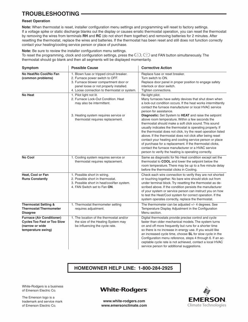
Symptom Possible Cause Corrective Action
No Heat/No Cool/No Fan (common problems)
1. Blown fuse or tripped circuit breaker. 2. Furnace power switch to OFF. 3. Furnace blower compartment door or panel loose or not properly installed. 4. Loose connection to thermostat or system.
Replace fuse or reset breaker. Turn switch to ON. Replace door panel in proper position to engage safety interlock or door switch. Tighten connections.
No Heat 1. Pilot light not lit. 2. Furnace Lock-Out Condition. Heat may also be intermittent. 3. Heating system requires service or thermostat requires replacement.
Re-light pilot. Many furnaces have safety devices that shut down when a lock-out condition occurs. If the heat works intermittently contact the furnace manufacturer or local HVAC service person for assistance. Diagnostic: Set System to HEAT and raise the setpoint above room temperature. Within a few seconds the thermostat should make a soft click sound. This sound usually indicates the thermostat is operating properly. If the thermostat does not click, try the reset operation listed above. If the thermostat does not click after being reset contact your heating and cooling service person or place of purchase for a replacement. If the thermostat clicks, contact the furnace manufacturer or a HVAC service person to verify the heating is operating correctly.
No Cool
1. Cooling system requires service or thermostat requires replacement.
Same as diagnostic for No Heat condition except set the thermostat to COOL and lower the setpoint below the room temperature. There may be up to a five minute delay before the thermostat clicks in Cooling.
Heat, Cool or Fan Runs Constantly
1. Possible short in wiring. 2. Possible short in thermostat. 3. Possible short in heat/cool/fan system. 4. FAN Switch set to Fan ON.
Check each wire connection to verify they are not shorted or touching together. No bare wire should stick out from under terminal block. Try resetting the thermostat as de-scribed above. If the condition persists the manufacturer of your system or service person can instruct you on how to test the Heat/Cool system for correct operation. If the system operates correctly, replace the thermostat.
Thermostat Setting & Thermostat Thermometer Disagree
1. Thermostat thermometer setting requires adjustment.
The thermometer can be adjusted +/- 4 degrees. See Temperature Display Adjustment in the Configuration Menu section.
Furnace (Air Conditioner) Cycles Too Fast or Too Slow (narrow or wide temperature swing)
1. The location of the thermostat and/or the size of the Heating System may be influencing the cycle rate.
Digital thermostats provide precise control and cycle faster than older mechanical models. The system turns on and off more frequently but runs for a shorter time so there is no increase in energy use. If you would like an increased cycle time, choose SL for slow cycle in the Configuration menu reference, steps 4 through 6. If an ac-ceptable cycle rate is not achieved, contact a local HVAC service person for additional suggestions.
Reset Operation
Note: When thermostat is reset, installer configuration menu settings and programming will reset to factory settings. If a voltage spike or static discharge blanks out the display or causes erratic thermostat operation, you can reset the thermostat by removing the wires from terminals RH and RC (do not short them together) and removing batteries for 2 minutes. After resetting the thermostat, replace the wires and batteries. If the thermostat has been reset and still does not function correctly contact your heating/cooling service person or place of purchase.
Note: Be sure to review the installer configuration menu settings. To reset the programming, clock and configuration settings, press the , and FAN button simultaneously. The thermostat should go blank and then all segments will be displayed momentarily.
TROUBLESHOOTING
HOMEOWNER HELP LINE: 1-800-284-2925
White-Rodgers is a business of Emerson Electric Co.
The Emerson logo is a trademark and service mark of Emerson Electric Co.
www.white-rodgers.comwww.emersonclimate.com