Embed Size (px)
Citation preview
212 .6 88 SE
1i> ITATION
.JOJECT
Operated by CDM and Associates
Sponsored by the U.S. Agency for International Development
1611 N. Kent Street, Room 1002 Arlington, VA 22209-2111 USA
Telephone: (703) 243-8200 Telex No. WW 64552
Cable Address WASHAID
THE SELECTION OF DRLLING RIGS
FOR RURAL WATER SUPPLY
•."-RARY
l,-.-T.i.;.-JA-'HONAL REFERENCE CENTRE FOR COMMUNITY WATER SUPPLY. ANQ SANITATION ilKGJ
WASH TECHNICAL REPORT NO. 42
APRIL 1988
The WASH Project is managed by Camp Dresser & McKee International Inc. Principal cooperating institutions and subcontractors arc: Associates in Rural Development, Inc.; lnternation.i l Science and Technology Institute, Inc.; Research Triangle Institute; Training Resources Croup; University of North Carolina
Prepared for the Office of Health,
Bureau for Science and Technology U.S. Agency for International Development
WASH Activity No. 259
WASH TECHNICAL REPORT NO. 42
THE SELECTION OF DRILLING RIGS FOR RURAL WATER SUPPLY
Prepared for the Office of Health, Bureau for Science and Technology U.S. Agency for International Development
under WASH Activity No. 259
by
r LIBRARY, INTERNATIONAL REFERENCE jj CENTR" !:OR CO;/M:.tt:t i'Y WAVER SUPPLY i
! P.O. Do- 'J3'C.K:, 2^.09 AD Tho 1-is.guo
j Tel. (070) 3 i 4 9 ! i cxt 141/142
Ralph E. Preble j and c
P h i l i p Roark
Apr i l 1988
Water and Sanitation for Health Project
Contract No. S942-C-00-4085-00, Project No. 936-5942
is sponsored by the Office of Health, Bureau for Science and Technology
U.S. Agency for International Development
Washington, DC 20523
TABLE OP CONTENTS
CHAPTER Page
ACKNOWLEDGMENTS v
EXECUTIVE SUMMARY vii
1. INTRODUCTION 1
2. GENERAL CONSIDERATIONS IN DRILLING RURAL WELLS 3
2.1 Accessibility 3 2.2 Aquifer Characteristics 3 2.3 Diameters of Wells and Pumps 4 2.4 Well Depths 5
3. DRILLING METHODS 7
3.1 Cable Tool Drilling 7 3.2 Rotary Drilling Methods 9
3.2.1 Conventional Rotary Drilling 9 3.2.2 Rotary Percussion Drilling 10 3.2.3 Reverse Rotary Drilling 11
4. PERTINENT DRILLING RIG CONSIDERATIONS 13
4.1 General Considerations 13 4.1.1 Introduction 13 4.1.2 Weight 13 4.1.3 Truck Considerations 14 4.1.4 Maintenance and Spare Parts 14
4.2 Specific Considerations 15 4.2.1 Procedures Applicable to Overburden Wells 15 4.2.2 Principles Applicable to Overburden Drilling 16 4.2.3 Procedures Applicable to Bedrock Wells 19 4.2.4 Principles Applicable to Rock Drilling 20
4.3 Summary of Drilling Rig Specifications 23 4.3.1 Operational Specifications 23 4.3.2 Equipment Specifications 23 4.3.3 Basic Auxiliary Equipment 23
TABLE OF CONTENTS (continued)
CHAPTER Page
5. ACCESSORY DRILLING EQUIPMENT 25
5.1 General Discussion 25 5.2 Accessories Related to Drilling 26
5.2.1 Accessory Equipment for Overburden Drilling 26 5.2.2 Accessory Equipment for Air Percussion Drilling .... 28 5.2.3 Basic Accessories for Overburden Drilling and
Air Percussion Rock Drilling with Casings Limited to 4-inch (101.6 mm) Diameter 28
5.3 Miscellaneous Equipment 28 5.3.1 Water Tanks 28 5.3.2 Hydrofracturing Equipment 33
6. COMPARISON OF SELECTED DRILLING RIGS 35
7. TRAINING 39
7.1 Formal Driller Training 39 7.2 In-Country Supervision and Training 39
8. CONCLUSIONS 41
BIBLIOGRAPHY 45
APPENDIX
A. Ground Water in Hard Rocks 49 B. Support Vehicle for Drill Rig Crew 55 C. Down-the-hole Drills 61 D. Mud Tank 65 E. Hydrofracturing Pump 69 F. Deep Rock Literature 75 G. Canterra Literature 81 H. Simco Literature 91 I. Failing Literature 101 J. Gus Pech Literature Ill K. Mobile Literature 119 L. Water Well Education 127
- ii -
TABLE OF CONTENTS (continued)
Page
TABLES
1. Relative Performance of Different Drilling Methods in Various Types of Geologic Formations 8
2. Accessory Equipment for Overburden Drilling 27 3. Accessory Equipment for Air Percussion Drilling 29 4. Basic Accessory Equipment for Wells Completed with Well
Screens in Unconsolidated Formations 30 5. Basic Accessory Equipment for Wells Completed in Bedrock
by Air Percussion Drilling 31 6. Drilling Fluids for One Lightweight Drill Rig 32 7. Top-Head Drive Drill Rigs with 7,500 lb, or less,
Operating Weight 36 8. Top-Head Drive Drill Rigs with Operating Weight over 7,500 lbs ... 37 9. Checklist of Considerations Influencing Drill Rig Selection 42
- iii -

ACKNOWLEDGMENTS
The authors wish to thank David Grey of the Water and Sanitation Division of the World Bank for his review of this report.

EXECUTIVE SUMMARY
This report considers the conditions under which rural water supplies are typically constructed and provides guidelines on the selection of drilling rigs appropriate for these conditions. Drill rigs of a size larger than necessary for most rural applications have been employed in the past, and this has resulted in unnecessarily high costs and less flexibility in reaching isolated locations. The need to find cost-effective means of providing rural water supplies has resulted in increased emphasis on smaller, light-weight drilling rigs.
The majority of rural water supply projects can be expected to rely on wells equipped with handpumps or other pumps of relatively low capacity. Wells yielding about 10 m /day, constructed with 4 to 6 inch PVC casing, and about 30 meters average depth will satisfy most village needs in developing countries. Drill rigs will usually need both a rotary capability, to handle soft overburden materials, and an air percussion capability, to penetrate hard rock. Light-weight mobility is needed in drill rigs to traverse difficult terrain.
The key selection criteria for drill rigs include the following:
capable of drilling to 75 meters (250 feet)
boreholes for 4 to 6 inch casing
both rotary and air percussion capability
light weight
low cost.
Success in rural water supply programs can be enhanced by proper selection of cost-effective drilling equipment. These guidelines are addressed to project designers and managers in drill rig selection and procurement. Examples of specific drill rig models are given, along with accessory drilling equipment, with a discussion of their relative merits. In addition to the technical components of rural water development, emphasis must also be placed on community organization and health education to assure full benefits of water supply to rural inhabitants.
- vii -

Chapter 1
INTRODUCTION
A changing emphasis in rural water well construction within developing countries has occurred in the last two decades. Traditionally, wells have been constructed by hand digging and the resulting well diameters were necessarily large, usually greater than 1.5 meters. Modern hand-dug wells have been concrete-lined and in many cases capped to reduce contamination. In order to avoid the possibility of reduced water supplies during droughts in relatively shallow hand-dug wells, more emphasis has been placed on drilled wells which penetrate deep into aquifers. Both large-diameter capped wells and small-diameter drilled wells require a pumping device, usually a handpump. Problems associated with the operation and maintenance of handpumps, however, has led to generally unsatisfactory results in many projects.
In more recent years, technical improvements in handpumps and institutional improvements in operations and maintenance of systems have generated more confidence in handpumps. Today's handpumps tend to be more robust to withstand heavy community use and can be maintained at the local level. Some handpumps can be manufactured locally, which relieves the problem of importing spare parts. With improved performance of handpumps the construction of wells through drilling has become less problematic. Compared to hand-dug wells, drilled wells are faster to construct and are more reliable because of increased depths. These are important considerations to water development planners which, along with the improved pumps, have led planners to place major emphasis on drilled water wells.
The expected drop in cost of drilling new wells has not occurred, however. One reason for this is that a significant portion of the construction cost lies in the purchase price of drilling rigs. The delivered price of a fully equipped medium-sized rotary drilling rig, such as those found in water development projects surveyed in Africa, can reach $500,000 or more. In addition, the larger drilling rigs with complex technical and mechanical components often proved to be beyond the capabilities of the operators, mechanics, and logistic support staff to efficiently use and maintain them. This resulted in low production and consequently high amortized costs per well. Because of such high costs development specialists and some manufacturers are putting more emphasis on smaller drilling rigs that are better suited to the needs and conditions of rural water development. If the water needs of rural inhabitants in developing countries are to be met, more emphasis in the future will necessarily be placed on cost-effective water drilling projects.
The purpose of this report is to describe typical conditions under which rural water systems are constructed and to describe selected drilling rigs which are appropriate for those conditions. It is expected that international development agencies, government water development agencies, and private sector drilling contractors engaged in rural water supply projects will find the information useful. The guidelines are addressed to project designers and managers who are involved in drill rig selection and procurement.
- 1 -
The information contained in this report represents the personal experience of the authors, the cumulative experience of the WASH project, and personal communication with other international agencies and organizations. Specific reference is made to particular manufacturers of drilling rigs and related equipment. These references are not meant to endorse particular products, nor to cover all possible equipment, but rather to be used as examples. Further, most of the products mentioned are of U.S. manufacture, but equipment of non-U.S. origin may be equally suitable in many instances.
- 2 -
Chapter 2
GENERAL CONSIDERATIONS IN DRILLING RURAL WELLS
The conditions under which rural vater projects in developing countries are carried out vary widely. They can, however, be generalized to consider the appropriateness of particular drilling rigs. Factors common to water supply projects include the accessibility of proposed drilling sites, aquifer characteristics and yields, and veil diameters and depths.
2.1 Accessibility
Most rural well-drilling projects are located long distances from urban centers and are often in areas where access is difficult. Roads are often poor or even nonexistent. Moving heavy equipment into such areas can be a very difficult undertaking. Oversized drilling equipment is clearly not effective under such conditions and represents a drain on limited resources.
The purpose of rural water projects is to provide clean and easily accessible water to the village. It is important to place the well as close to the village center as possible in order to minimize the distance that people must travel to collect the water. Often, this means moving the rig to locations which are some distance from existing roads or trails.
In remote locations, a great amount of accessory materials and equipment must accompany the rig. Crews are often expected to stay in the field for weeks at a time. Such items as fuel and water for the drilling operations, casing and pumps for the well, and food and camping equipment for the crew must be transported to the site.
2.2 Aquifer Characteristics
Water-bearing formations vary considerably worldwide. For example, wells drilled in the alluvial deposits of the Indus or Ganges basins call for methods different from those appropriate to the hard metamorphic and crystalline rock areas of Africa. About 90 percent of the village wells in Uganda are begun in weathered basement material and completed in bedrock. Conditions can also vary widely within a single small country. In El Salvador, potential groundwater development varies from coastal plain alluviums to a variety of crystalline rocks, metamorphic rocks, and rocks composed of pyroclastic materials. In most countries drilling conditions will necessitate a choice of drilling equipment that is capable of efficiently installing wells in both unconsolidated sands and gravels as well as hard bedrock.
Aquifers also vary considerably and are often low in yield. For village water supply purposes, yields of as little as 10 m /day are sufficient to meet the minimal needs of small villages of about 250 people. This yield is the capacity of typical handpumps when used at depths of less than 30 meters.
- 3 -
In areas where yields are low, aquifers or water-bearing zones are often difficult to locate. Repeated drilling attempts may be necessary at a particular site. This is especially true when drilling in bedrock where wells are located through fracture trace analysis or in other formations where adequate geophysical techniques are not available. To keep total operational expenses at a minimum, low-cost, very mobile drilling equipment is needed at such sites.
2.3 Diameters of Wells and Pumps
The selection of an appropriate well diameter for any drilling program is largely dependent upon the pump to be installed. Some rural well drilling programs, in addition to drilling village wells to be equipped with handpumps, include communities where larger wells are necessary to accommodate power-driven pumps. However, the great majority of wells in a rural well program will be equipped with handpumps. Handpumps are produced in a variety of different designs. Most handpumps are designed to lift or force water through a "drop pipe," commonly referred to as a "column pipe," to the ground surface. Where the water is at a shallow depth, normally less than six meters below ground, suction handpumps are capable of lifting water by vacuum created by an above-ground piston in the pump body. Such pumps are normally attached to small-diameter wells of 1-1/4 to 2 inch (31.75 to 51.8 mm) diameter or large-diameter hand-dug wells. Small-diameter wells are commonly installed by methods other than motorized drilling rig.
In wells with a water level depth greater than 20 feet, the pump piston, or pump body of an alternate design, must be located below the water level. Such pump bodies normally range from 2-1/2 to 3 inches (63.5 to 76.2 mm) in outside diameter (0D) but some are smaller. Typically, development organizations have designed village wells to be cased with 5 or 6 inch (127 to 152.4 mm) inside diameter (ID) pipe sealed into bedrock with the drilling in rock completed with 4 or 4-1/2 inch (101.6 to 114.3 mm) bits. Other organizations with limited means, such as private voluntary organizations (PVOs), generally have relied upon 4 inch (101.6 mm) ID casing and 3-1/2 inch (88.9 mm) drill bits primarily due to the capital cost of equipment necessary to drill the larger boreholes. Small powered pumps are normally of 3-1/2 or 3-5/8 inch (88.9 or 92.1 mm) diameter and require casing of at least 4 inch (101.6 mm) diameter.
Generally, the design diameter of wells is determined by the quantity of water to be extracted, the necessary diameter being that which will permit setting a pump to achieve this extraction rate. The potential upper limit for a 4 inch (101.6 mm) well is about 300 to 350 gpm (19 to 22.1 1/s). The downhole piston of a handpump dictates the 4 inch (101.6 mm) size where water levels do not permit a handpump design that incorporates the piston in the pump chamber. The lower limit of acceptability for handpumps is based on user demand. Pumps which cannot achieve a pumping rate of at least 5 gpm (19 1/m) are considered unacceptable.
Borehole diameters must obviously be adequate to allow entrance of the well casing and screens (unless the well is completed "open hole" in stable rock formation). In addition, the size of the annular space (distance between the well casing and borehole wall) needs to be considered. The National Water
- 4 -
4 Well Association (NWVA) Standard for Deep Wells recommends a cement grout of at least 1-1/2 inch (38.1 mm) thickness. If this recommendation were to be adopted all 4-inch (101.6 mm) veils would be 7-1/2 inches (190.5 mm) in diameter in overburden materials and extend at least 10 feet (3.05 m) deep into bedrock for rock wells (another NWWA recommendation).
Many local methods of well installations employed in the developing countries neglect any form of seal between the casing and the borehole wall. Thousands of wells in Bangladesh were checked for fecal contamination between 1964 and 1974 under a USAID advisory assistance program and, invariably, problem wells were those in which contaminated water had been introduced into the well by the users.
In some formations a filter pack (gravel pack) is needed. The geologic conditions, availability of suitable filter pack materials, drilling method, and type of screen determine whether a filter pack is required. The minimum practical thickness for a filter pack is 3 inches (76 mm) thus, 7-1/2 inch (190.5 mm) boreholes equipped with 4-1/2 inch (114.3 mm) 0D screen are appropriate.
For purposes of this report, borehole diameters of 7-1/2 inch (190.5 mm) for overburden wells, 5-1/2 inch (139.7 mm) to seat casing into bedrock with 3-9/16 inch (90.5 mm) in the bedrock itself are recommended for wells intended for handpump installations. Casing and screen of 4-inch ID are recommended in these wells. In later chapters, 10-inch (25.4 mm) boreholes in overburden aquifers are also discussed. The larger diameter is necessary to accommodate powered-pump installation of 100 gpm (6.2 1/s) capacity, or more, when higher yields are required for villages with greater water demand.
2.4 Well Depths
Within the developing world there is a vast range of geologic conditions in which water may be found. Groundwater may occur, for example, in many parts of Bangladesh, within inches of the surface, or as deep as many thousands of feet in the Sierra Madre province of Mexico. In some locations throughout the world, groundwater at a specific location may not be found at any depth. Fortunately, in most areas of the world, groundwater is available in adequate quantities for small rural village needs at depths less than 60 meters (200 feet). The median pumping lift for rural water supply wells worldwide is 12 meters (40 feet) with 90 percent of pumping depths less than 30 meters (100 feet).
Even in areas underlain by hard rock, such as crystalline granites or gneisses, water is often available in the weathered or fractured zone above the bedrock in limited quantities at modest depths. Appendix A provides some selected worldwide examples of depths and water yields in hard rocks.
For the purposes of this report, a maximum depth of 75 meters (250 feet) is recommended as an appropriate specification to which drilling rigs designed for village water supply should be capable of reaching.
- 5 -

Chapter 3
DRILLING METHODS
Geologic conditions are usually the most important factor in determining the type of drilling rig and method of drilling for a specific program. The relative performance of various methods of drilling in different types of formations have been rated by Driscoll as shown in Table 1. While Table 1 lists several methods of drilling, three are most suitable for rural water supply projects—cable tool, rotary, and reverse rotary. In the following subsections, each method is briefly described and its advantages listed.
3.1 Cable Tool Drilling
Modern tools used in cable tool drilling are stronger and heavier than those used a century ago, but the drilling rigs have changed little since internal combustion engines replaced steam power in this century. Drilling is accomplished by lifting and dropping a string of tools (bit, drill stem, jars and swivel socket) suspended on a cable. Steel casing is driven down at periodic intervals as the borehole is advanced. Bit cuttings are also periodically removed from the borehole by a bailer.
When well production rate is not a critical factor, cable tool rigs have merit in many instances. They offer versatility in operating in all types of formations and their relatively low purchase price and operating costs are attractive. Where soft geologic formations dominate, labor costs are low, and skilled mechanics are in short supply, then cable tools should be considered.
The major advantages of the cable tool method of drilling in relationship to other drilling methods are:
1. Lower initial equipment costs (although some very light-weight rotary drills are comparable in price)
2. Low operating costs
3. Ease of repair due to simple and rugged rig design
4. Minimal or no water requirements for drilling
5. Versatile to operate in all geologic conditions
6. Less difficulty with loose cobbles or boulders than most drilling methods
7. Ability to drill, develop, and test pump with same rig
8. Easy access to sampling of water levels and water quality.
- 7 -
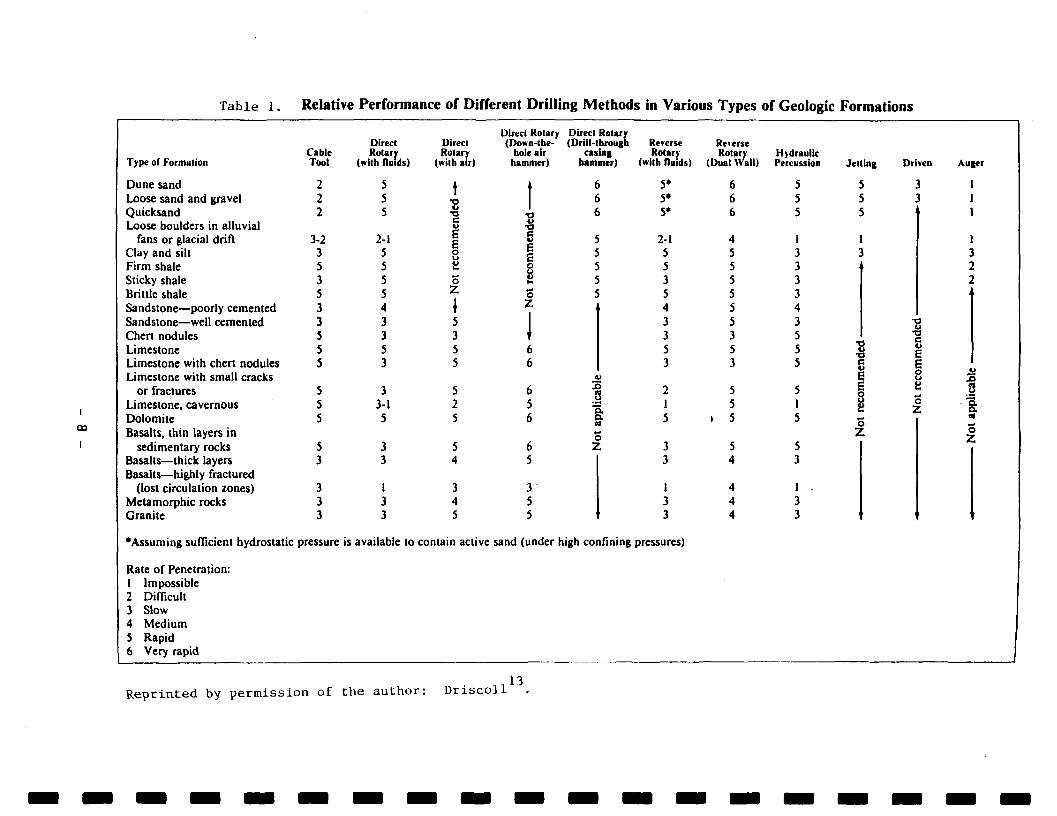
Table 1. Relative Performance of Different Drilling Methods in Various Types of Geologic Formations
Type of Formation
Dune sand Loose sand and gravel Quicksand Loose boulders in alluvial
fans or glacial drift Clay and silt Firm shale Sticky shale Brittle shale Sandstone—poorly cemented Sandstone—well cemented Chert nodules Limestone Limestone with chert nodules Limestone with small cracks
or fractures Limestone, cavernous Dolomite Basalts, thin layers in
sedimentary rocks Basalts—thick layers Basalts—highly fractured
(lost circulation zones) Metamorphic rocks Granite
'Assuming sufficient hydrostatic
Rate of Penetration: 1 Impossible 2 Difficult 3 Slow 4 Medium S Rapid 6 Very rapid
Cable Tool
2 2 2
3-2 3 5 3 5 3 3 5 5 5
5 5 5
5 3
3 3 3
pressure
Direct Rotary
(with fluids)
5 5 5
2-1 5 5 5 5 4 3 3 5 3
3 3-1 5
3 3
1 3 3
Direct Rotarv
(with air)
\ •a
c E E o o o o
z \ 5 3 5 5
5 2 5
5 4
3 4 5
Direct Rotary Direct Rotary (Down-the- (Drill-through Reverse Reverse
hole air casing Rotary Rotary Hydraulic hammer) hammer) (with fluids) (Dual Wall) Percussion
i 6 5* i 6 5* (
i 6 5* ( •a S 5 2 - 1 4 1 5 5 3 § 5 5 ! £ 5 3 5 3 5 5 i Z \
J 6 6
4 i 3 I 3 1 5 i 3 1
V
6 -g 2 i 5 J 1 5 6 ft 5 . 5
© 6 Z 3 i 5
3 5 5
3 A
i A 3 4 3 A
is available to contain active sand (under high confining pressures)
> 5 > 5 > 5
1 3 3 3 3 4 3 5
» 5 1 5
5 1 5
5 3
1 . 3
\ 3
Jetting Driven Auger
5 5 5
1 3 .
$ l 3 1
1
1 3 2 2 .
4)
C
*o i
E
L>
2 M
,
3 Js •i -o 1 ! .5
8 f 1 o 2
' 1
« o •7 i*
•
1
l
Reprinted by permission of the au thor : D r i s c o l l 13
The major disadvantages of the cable tool method are:
1. Limited penetration rate (although for some formations it is relatively rapid if wells are shallow)
2. The need to drive casing requires heavy steel pipe which adds to transport and handling problems and offsets, to a degree, other potential economies.
3. Frequent drill-line failures
4. Temporary casing required in unconsolidated materials.
Most references list limited depth capability as a disadvantage of the cable tool method but, for rural drilling programs where depths do not exceed 200 feet, this would not be a problem. The significantly slower penetration rate, however, is a disadvantage except possibly for small-scale programs with no time limits or production goals. In the experience of the authors, the penetration rates shown in Table 1 are possibly overestimated, particularly when drilling in very hard metamorphic and crystalline rocks or when wells become rather deep. A theoretical production rate indicated by Larsson suggests that cable tool drilling can construct 20-40 wells/year as compared to 150-175 wells/year by rotary/percussion drilling based on 200-foot (60 m) deep wells and a 220-day working year. The actual production rate for either method is usually much less in developing countries because of problems in logistics, support services, and management. Whenever speed is considered important, and it should be whenever cost effectiveness is an issue, then cable tool rigs are not generally recommended.
3.2 Rotary Drilling Methods
3.2.1 Conventional Rotary Drilling
Conventional rotary drilling is a method of boring a hole by using a rotating bit to which a downward force is applied by a hollow drill stem or rods. The hollow drill rods conveys a drilling fluid (in recent years air has also been utilized) to the bit for moving the cuttings to the surface in the annular space between the drill rods and the sides of the borehole.
Bentonite (a clay material) or polymers are added to the drilling fluid to provide stability to the walls of the borehole and prevent them from collapsing. In some areas the natural clays in the formation provide sufficient stability. Such drilling is referred to as open-hole drilling and well completion is accomplished in unconsolidated aquifers by the insertion of a casing to which a well screen is attached. Depending upon the formation in which the well screen is set the formation may be allowed to collapse around the well screen. More commonly, the annular space between the borehole walls and screen is filled with gravel (filter pack).
- 9 -
The rotary method of drilling is relatively rapid and one or two shallow wells per day can be installed, assuming the distance between wells is not great. This method is also used, with differently designed drill bits, to drill weathered bedrock wells where the overlying unconsolidated materials are found to be poor aquifers.
Various PVOs have, in recent years, purchased and employed very light-weight drilling rigs to complete wells in both unconsolidated overburden aquifers and bedrock, aquifers by conventional rotary methods. However, major rural water supply programs funded by UNICEF and various international government agencies have preferred down-the-hole hammer drilling when a major part of the program involved wells completed in hard rock aquifers.
3.2.2 Rotary Percussion Drilling
In rotary percussion drilling a down-the-hole hammer, activated by air from an air compressor, is used. This method was developed from the conventional fluid rotary method, and drill rigs are capable of drilling by either means if a fluid circulating pump and appropriate auxiliary equipment are available.
Larsson16 lists the advantages of the rotary percussion method as follows:
1. High penetration rate
2. Excellent depth capability
3. Good control of fluid flows
4. Combination drilling (unconsolidated and consolidated formations)
5. No special circulation monitor required unless special additives are used
6. Minimum damage to water-bearing zones
7. Quick set-up time for rig
8. Good samples recovered and effective identification of water-bearing zones.
The major disadvantages listed are:
1. Medium to high equipment cost
2. Medium to high operating costs
3. Medium transportation costs—heavy-duty, truck-mounted rig plus compressor
4. Need for experienced drilling personnel.
- 10 -
The problem of heavy, truck-mounted rigs has been lessened in recent years. A number of manufacturers such as Deep Rock, Canterra, and the Swedish
* manufactured WellDrill (now owned by Atlas Copco) are producing very lightweight trailer-mounted rigs which can combine both conventional fluid rotary and down-the-hole hammer capability. Major manufacturers are also marketing somewhat larger trailer-mounted rigs with similar but somewhat greater borehole diameter and depth capabilities. The drilling methods which presently offer the most advantages for rural well drilling programs are conventional rotary drilling in unconsolidated aquifers and down-the-hole hammer drilling in bedrock aquifers with drilling rigs that can efficiently drill by either method.
3.2.3 Reverse Rotary Drilling
Reverse rotary drilling is a method of well construction that is commonly used for large-diameter, high production wells in unconsolidated aquifers which are generally free of large cobbles and boulders. The well rig acts as a vertical dredge with the drilling fluid, normally water without additives, and cuttings being drawn up through the drill stem. It is an open-hole form of drilling dependent on maintaining a liquid level in the open hole of 10 feet (3 m) or more above that which is naturally present. To accomplish this a reliable source of water, to compensate that lost to the formation being drilled, is needed. The amount of makeup water needed can range from 20 to 500 gpm (1.26 to 31.5 1/s).
In past years, a 6-inch (183 mm) flanged drill stem was most often employed with either a pump or air lift creating an up-stem velocity, according to Driscoll13, of at least 1.5 ft/sec (0.76 m/sec). Such drill stems limited borehole diameters to 18 inches (457 mm) or larger, so downhole return flow could be kept under 1 ft/sec (0.305 m/sec) to prevent side hole erosion. In the 1960s Bengali and Thai well drillers were utilizing standard 3- and 4-inch (76 and 102 mm) threaded and coupled pipe for reverse rotary drill stems and drilling 12-inch (305 mm) boreholes with locally fabricated rigs. Most new drill stems are now threaded and coupled to reduce the labor of making connections.
Driscoll13 notes that an adaptation of reverse rotary drilling using top head drive rigs and air for lifting cuttings is called an In-Verse system. Another adaptation of reverse rotary drilling is a dual wall method. With this system a special steel inner tube, connected with sleeves and 0-rings, is enclosed within flush joint screwed pipe. Drill pipe diameters range from 3-1/2 to 9-5/8 inches (89 to 244 mm) and drilling is done by either tri-cone or down-the-hole hammer bits. With this method drill cuttings travel up in the inner tube and return flow is between the tube and the outer drill pipe.
Advantages of reverse rotary drilling are:
1. It is a relatively inexpensive method of drilling large diameter boreholes in soft unconsolidated sediments.
2. Relatively reliable samples of formation can be obtained as cuttings do not come in contact with the sides of the borehole in their ascent.
- 11 -
3. The drilling fluid is normally clear water, so adequate well development is not difficult to achieve.
Disadvantages of reverse rotary drilling are the following:
1. It cannot be used if the static water level is too high (although in Pakistan a mound is built to raise the rig).
2. Relatively large amounts of makeup (supplemental) water are necessary.
3. Stiff clay, shale, or boulders present problems that are impossible to handle.
4. It is not normally suitable for drilling in consolidated rock formations.
5. Rapid penetration makes the depth from which sample is obtained difficult to judge.
6. Samples often do not contain fines because of being washed in collection process.
The dual well reverse rotary method was introduced to water well projects in recent years from the oil and mineral industry. The advantages of drilling large-diameter wells in unconsolidated formations are offset by high costs and weight. Augers are four to five times the cost and at least twice the weight of conventional rotary drill stems. Thus, it is considered an unattractive option for most rural well programs.
- 12 -
Chapter 4
PERTINENT DRILLING RIG CONSIDERATIONS
4.1 General Considerations
4.1.1 Introduction
After considering the geologic conditions and appropriate drilling methods described in the preceding chapters, the specific character of drilling equipment and the inherent limitations involved must be examined. General considerations include weight of the equipment and the related capacities of trucks to move the equipment. Spare parts and maintenance are also important considerations. More specific requirements relate to the actual drilling under bedrock and overburden conditions. These subjects are discussed in the following paragraphs.
4.1.2 Weight
As discussed in Chapter 3, most drilling conditions will require a drilling rig that can combine the operations of conventional fluid rotary and down-the-hole air hammer capability. Such rigs may be either trailer-mounted or truck-mounted. The choice of the most suitable mount must consider total weight and also weight distribution of the rig and its accessory equipment. Weight is a factor both in negotiating difficult terrain where steep inclines and bridges with limiting capacities are present, and in selecting trucks with sufficient power to haul or pull the required equipment.
Selection of equipment is sometimes a complex problem requiring trade-offs between alternatives. For example, some references suggest a probable maximum torque requirement of 2,000 foot-pounds for down-the-hole hammers in hard rock drilling. While this requirement is true, it fails to recognize the need to drill through an unconsolidated layer to reach the bedrock in a majority of instances. Also, rock drilling torque provides more uniform rotation and generally better production. Torque and weight are, to a degree, interrelated as power is required to generate torque and this power is responsible for added weight. Mud pumps of adequate capacity also require power. These factors can add 50 percent or more to the needed horsepower to be built into the unit, and added horsepower translates into added weight.
Weight also enters into the matter of transporting equipment. If a trailer-mounted rig cannot be pulled by a pick-up truck, it is probably more efficient to mount it on a heavier truck. If, however, the weight of the truck then exceeds the capacity of the bridges in the area, alternative routes or sites must be considered.
- 13 -
While many development organizations rely upon a fleet of mini pick-ups (normal towing capacity in the 2,000 to 3,500 pound [900 to 1,600 kg] range) these are not sufficient for most drilling operations. As a general criterion, a maximum axle weight in a range of 5,000 to 6,000 pounds (2,300 to 2,700 kg) is required.
4.1.3 Truck Considerations
Within most operations, the combined weight of truck and drilling equipment exceeds 6,000 pounds (2,700 kg), and, except for the very light-weight rigs with separate trailer-mounted air compressors, rules out truck-mounted drilling rigs. The adopted maximum single axle loading, with a 12,000-pound (5,000 kg) rig trailer, is in excess of the rated trailer hauling capacity of the four-wheel-drive Chevrolet V-20 (or equivalent GMC) with a trailer hauling package or the four-wheel-drive GMC Jimmy V-15 which might be considered for somewhat lighter equipment. However, the Ford F-250 HD with its Caterpillar-built 168 H.P., 420 cu.in. diesel, as compared to a General Motors 130 H.P., 379 cu.in., and up to 14,000-pound (or greater) GWCR* would be a wiser choice for towing weights in the 10,000-pound to 12,000-pound range.
In any event, the aim is to minimize the single axle load for towing truck and trailer-mounted rig and standardize on two identical pickup body trucks to provide full moving capability for the drilling team and its equipment. Specifications and manufacturer's description for this truck are reproduced in Appendix B. Other truck models may be competitive price-wise and offer other advantages when towing weights are less than 8,000 pounds 3,600 kg), but advantages of leaving drill rods on the rig would give preference to Ford even with drill rigs in the 7,000-pound (3,200 kg) weight range.
4.1.4 Maintenance and Spare Parts
Rig manufacturers and well-managed drilling organizations would like to see a general minor maintenance check after 50 hours of operation and an overhaul after 2,000 hours. In addition to the drilling crew handling minor maintenance on a day-by-day basis, it is desirable, but seldom followed, to have a shop check after the completion of a program in one geographic area. However, this might mean 3 weeks or longer before anyone, other than operating personnel, checks the condition of the equipment. Manufacturers' recommendations vary, and, while circumstances may not permit strict compliance, responsible field personnel need to be instructed and repeatedly reminded that daily and periodic field maintenance procedures cannot be neglected. Scheduled oil changes, lubrication, etc., are as important as filling the fuel tank.
GWCR is "gross weight combined rating." This refers to combined truck cargo and trailer weight. While Ford only rates the F-250 HP diesel at 10,000 pounds, it has substantially greater capability than other options. It is usable with up to 12,000-pound trailers.
- 14 -
The influence of standardization, repairs, maintenance and spare parts for past UNICEF procurement was discussed in a World Water6 article. Most U.S. drilling firms are not overly concerned about standardization of a drilling rig. Replacement parts are readily and quickly available through air shipment. Rig preference appears to be based on evidence, personal or otherwise, of rig reliability and the ability to do the job for which it was intended. These considerations have generally lead to the selection of oversized equipment. This is not necessarily the case for very light-weight drilling equipment such as that manufactured by Deep Rock or the rigs by the Swedish firm Deepwell which have had a market with PVOs for some years. Just because a country may presently operate large equipment manufactured by Ingersoll-Rand, Failing, or others, is no reason to select lighter-weight equipment by these manufacturers for a rural well drilling program when equipment by another manufacturer will do the job more efficiently at lower overall cost.
Supplies need to be ordered for drilling programs in developing countries well in advance of actual need. Spare parts which are most frequently needed should be ordered in volume on an annual basis, as several months are often required for delivery. Savings by shipping via ocean freight are usually quite significant. While most spare parts for drill rigs will probably not be available locally, it is important to be aware of those which are available either locally or from regional distributors.
Overstocking of spare parts or materials should also be avoided, as warehouse rentals add to project costs. Proper inventory control, which provides signals to project managers when important spares are in low supply, is essential. It will always be necessary to provide emergency spare parts for unanticipated breakdowns, and a budget for air freight is therefore needed. The key to cost-effective operation of drill rigs is to keep them in operation and avoid long delays for repairs.
4.2 Specific Considerations
The discussion above has described a light-weight, trailer-mounted, well drilling rig with both fluid rotary and down-the-hole hammer drilling capability as being the best choice for most rural well programs. Trucks to move the equipment, tools, and supplies are also needed. Before discussing accessory items and comparing different manufacturers' equipment, certain specifics of operation and operational limitations of the drilling and accessory equipment need to be examined. The procedures and principles discussed in the following subsections are directly related to the evaluation and comparison of the standard features and optional equipment offered by different manufacturers.
4.2.1 Procedures Applicable to Overburden Wells
Wells completed in permeable overburden aquifers may not need to be installed with the equipment described herein. Shallow overburden veils may be more efficiently installed by local hand drilling methods or by utilizing cable tool equipment. Such wells may need a gravel pack to surround a well screen.
- 15 -
Low-capacity wells, for handpump installation, are generally installed without gravel packs in the Indus and Ganges alluvial deposits as well as elsewhere. Generally, gravel packs are recommended in alluvial materials particularly with higher capacity wells. For drilling of overburden wells the following conditions and approach are anticipated:
• Where wells are to be installed with fluid rotary equipment the use of a drilling fluid made with degradable polymers should be considered to simplify well development.
• Drilling with drag bits would normally be practiced.
• Drag bits in a variety of sizes up to 10 inches (25.4 mm) should be provided to accommodate installation of surface seals and/or gravel pack well construction where needed.
• Well casings and well screens should be PVC materials in a 4 inch (101.6 mm) ID size where the pump cylinder is to be set in the well casing, and a smaller size where water table conditions allow for a pump with the cylinder incorporated into the above-ground pump housing.
• Flush joint PVC casing and screen with cut threads for screw-together joining is recommended. Solvent cement socket joints are also acceptable for shallow wells.
• Local fabrication of PVC well screens is possible in some countries. Generally, local extruded and horizontally slotted PVC is acceptable. Local manufacture of continuously slotted ribbed pipe is also possible for particular purposes as described in Report on Broached Roboscreen (Sternberg and Knight27). Drilling projects should, however, rely on standard manufactured screens until local pipe cutting facilities are fully operational.
4.2.2 Principles Applicable to Overburden Drilling
With the type of drilling equipment under discussion, drilling for the purpose of completing a well in permeable overburden material is anticipated to be done through use of a fluid flush method. It is expected that both roller bits and drag bits will be utilized in such operations. To be effective, roller bits require considerably more weight to be applied to the bit, as discussed in Subsection 4.2.4, than do drag bits. Drag bits are capable of excellent penetration rates but require considerably more torque to operate successfully.
- 16 -
Adequate torque for drag bits is considered to be 200 foot pounds (ft lb) per inch by bit diameter (27.75 kg-m). A greater torque capability is probably desirable but excess torque should not be a major selection factor and equipment operation can be successful where the capability is less than quoted. On the basis of the figure quoted torque requirements would be as follows:
• 1,500 ft lb (208 kg-m) for 7.5 inch (190.5 mm) drag bits
• 2,000 ft lb (277 kg-m) for 10 inch (254 mm) drag bits
Rotation speed for drag bits is generally suggested to be between 100 and 200 rpm and somewhat higher for roller bits. In practice rotation normally does not exceed 100-110 rpm but rotation of roller bits, operated in unconsolidated materials, might be turned at 150 rpm or even higher by some operators. Successful drillers are ones who, through experience, possess the judgment to maintain a proper balance (combination) of rotation speed and weight on the bit. This judgment depends on being thoroughly familiar with the equipment being operated and paying careful attention to its sounds, vibrations, and general progress.
Fluid circulation pumps are rated according to the amount of fluid they will deliver at a certain head (pressure). Pumps capable of producing an up-hole velocity of 80 to 90 ft/min (40.6 to 45.7 cm/sec) should be adequate for drilling unconsolidated formations with drilling muds or polymers. A higher velocity might be desirable if drilling is in rock with a high specific gravity or if the rock particles to be flushed are large. This requirement might be 20 percent less under good drilling conditions without circulation losses.
To determine pump capacity the relationship between the size of the borehole, the size of the drill pipe, and pump delivery must be assessed so that a workable combination is achieved. This relationship is approximately expressed by the following formula:
V (D2-d2) Q = 2 5 —
Where: Q = pump discharge in gpm (gallons per minute)
V = up-hole velocity in ft/min (feet per minute)
D = borehole diameter in inches
d = drill pipe size (outside diameter) in inches
25 = a constant normally used for the units employed (24.46 an actual figure)
- 17 -
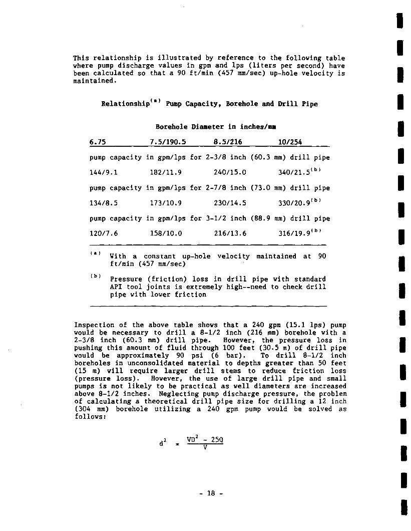
This relationship is illustrated by reference to the following table where pump discharge values in gpm and lps (liters per second) have been calculated so that a 90 ft/min (457 mm/sec) up-hole velocity is maintained.
Relationship Pump Capacity, Borehole and Drill Pipe
Borehole Diameter in inches/ma
6.75 7.5/190.5 8.5/216 10/254
pump capacity in gpm/lps for 2-3/8 inch (60.3 mm) drill pipe
144/9.1 182/11.9 240/15.0 340/21.5(b)
pump capacity in gpm/lps for 2-7/8 inch (73.0 mm) drill pipe
134/8.5 173/10.9 230/14.5 330/20.9(b)
pump capacity in gpm/lps for 3-1/2 inch (88.9 mm) drill pipe
120/7.6 158/10.0 216/13.6 316/19.9<b)
With a constant up-hole velocity maintained at 90 ft/min (457 mm/sec)
Pressure (friction) loss in drill pipe with standard API tool joints is extremely high—need to check, drill pipe with lower friction
Inspection of the above table shows that a 240 gpm (15.1 lps) pump would be necessary to drill a 8-1/2 inch (216 mm) borehole with a 2-3/8 inch (60.3 mm) drill pipe. However, the pressure loss in pushing this amount of fluid through 100 feet (30.5 m) of drill pipe would be approximately 90 psi (6 bar). To drill 8-1/2 inch boreholes in unconsolidated material to depths greater than 50 feet (15 m) will require larger drill stems to reduce friction loss (pressure loss). However, the use of large drill pipe and small pumps is not likely to be practical as well diameters are increased above 8-1/2 inches. Neglecting pump discharge pressure, the problem of calculating a theoretical drill pipe size for drilling a 12 inch (304 mm) borehole utilizing a 240 gpm pump would be solved as follows:
2 VD2 - 25Q
- 18 -
With units as described on page 17:
• This would be an impractical 8.8 in. (223 mm) drill pipe size for the problem stated
• For a pump with a 340 gpm discharge, a 7 inch (177 mm) drill size is required
• However, for a 10 inch (254 mm) drill hole a 2-3/8 (60.3 mm) drill pipe could be used if depth and resultant head loss was not to great. A 3-1/2 inch drill pipe would leave insufficient room for cuttings to pass in a 4 inch casing, a 4-1/2 inch (114.3 mm) drill pipe would be appropriate but, if used, in addition to unconsolidated drilling, with an air percussion hammer for bedrock. drilling would necessitate use of 6 inch casing.
4.2.3 Procedures Applicable to Bedrock Wells
While different well drillers may employ different methods to advance a drill hole through the overburden before drilling into a rock aquifer, the following conditions and approach are anticipated as being appropriate for drilling with the very light weight drill rigs (identified as those with less than 340 kg/m torque). A similar approach would be recommended for drill rigs over 340 kg/m torque anticipated to be used in programs requiring higher well yields except that 6-inch (152.4 mm) casing and larger rock bits would be recommended.
• A non-stable, potentially caving, permeable sand that is dry would be drilled in like manner to a permeable sand aquifer with a change to tricone bits to seat the casing into bedrock.
• If the bedrock is at a relatively shallow depth, the drilling of dry or saturated stable non-caving overburden material could be drilled with a 5.5 inch (140 mm) bit on a down-the-hole hammer. The depth to bedrock and type of overburden material will establish the need to set casing prior to drilling of the bedrock. Normally, prior to proceeding to drill in the bedrock, grout would be tremied to the bottom of the hole in an amount that would equal or slightly exceed the volume of the space between the installed casing and the borehole face opposite the rock section drilled for seating the casing. Under some circumstances casing would be grouted to the surface, but this would prevent cutting it off at depth and saving some portion from unsuccessful drillings.
- 19 -
• A 4-inch (101.6 mm) PVC casing (open end) is recommended. Various means of seating and sealing the casing into the bedrock may be adopted. The use of a grout pump to fill the space between the casing and the borehole side wall with cement grout to ground surface is a preferred method.
• It is suggested that casing comparable to SDR-17* water well PVC casing, with a wall thickness of 0.265 inch (6.7 mm), or Schedule 40, with a wall thickness of 0.237 (6.02 mm), be used.
• Following setting of the well casing the drilling in bedrock is anticipated to be undertaken with a 3-9/16 inch (90 mm) bit on a down-the-hole hammer. European hammer designs (British, Swedish, etc.), primarily those for drill holes less than 6 inch (152.4 mm) in diameter, are much more efficient than U.S. designs. Atlas Copco literature in Appendix C describes penetration rates, at 150 psi (10.5 bar) at 66 feet (20.1 m) per hour for a 3-9/6 inch (90 mm) bit. Most, if not all, U.S. models, in the same type of rock, only achieve a penetration rate of approximately two-thirds of this value.
• Well completion should be accomplished by development and hydrofracturing procedures where appropriate. Personal communication with UNICEF personnel and others indicates a belief that air percussion drilling pressures of 220 psi (15.2 bar) and up have a greater tendency to pack cuttings into water bearing fractures than does drilling at lower pressures.
4.2.4 Principles Applicable to Rock Drilling
The basic need for rural village water supply wells installed in a rock formation is to drill a hole capable of accepting a 3 inch (75 mm) O.D. pump piston. In hard metamorphic and crystalline rock this dictates (see discussion on drilling methods in section 3.3) employment of down-the-hole air percussion drills with 3-9/16 inch (90 mm) bits. Operation of such can be done through utilizing either 2-3/8 inch (60.3 mm) or 2-7/8 inch (73.0 mm) drill pipe operated in a 4 inch casing while maintaining a minimum chip clearance of drill pipe to wall of 5/16 inches (7.9 mm) as discussed in Campbell and Lehr . Adherence to this clearance would mean that 4-1/16 inch (110 mm) bits should not be run with 3-1/2 inch (88.9 mm) drill pipe, but larger bits could be used.
SDR - Standard Dimension Ratio
American Society for Testing Material nomenclature which sets forth the material, dimensional, and quality requirements for thermoplastic well casing. Other standards may be appropriate for non-US casing.
- 20 -
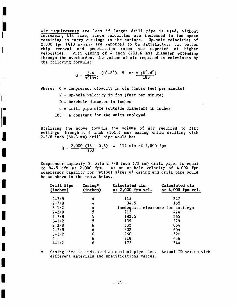
Air requirements are less if larger drill pipe is used, without increasing bit size, since velocities are increased in the space remaining to carry cuttings to the surface. Up-hole velocities of 2,000 fpm (610 m/min) are reported to be satisfactory but better chip removal and penetration rates are expected at higher velocities. With casing of 4 inch (101.6 mm) diameter extending through the overburden, the volume of air required is calculated by the following formula:
n 3.4 (D2-d2) V or V (D2-d2) u = 4(T34) I5T~
Where: Q = compressor capacity in cfm (cubic feet per minute)
V = up-hole velocity in fpm (feet per minute)
D = borehole diameter in inches
d = drill pipe size (outside diameter) in inches
183 = a constant for the units employed
Utilizing the above formula the volume of air required to lift cuttings through a 4 inch (101.6 mm) casing while drilling with 2-3/8 inch (60.3 mm) drill pipe would be:
n 2,000 (16 - 5.6) = 114 cfm of 2,000 fpm Q = TBI
Compressor capacity Q, with 2-7/8 inch (73 mm) drill pipe, is equal to 84.5 cfm at 2,000 fpm. At an up-hole velocity of 4,000 fpm compressor capacity for various sizes of casing and drill pipe would be as shown in the table below.
Calculated cfm Calculated cfm at 2,000 fpa vel. at 4,000 fpm vel.
114 227 84.5 165
inadequate clearance for cuttings 212 424 182.5 365 139 279 332 664 302 604 260 520 218 436 172 344
Casing size is indicated as nominal pipe size. Actual ID varies with different materials and specifications varies.
Drill Pipe (inches)
2-3/8 2-7/8 3-1/2 2-3/8 2-7/8 3-1/2 2-3/8 2-7/8 3-1/2 4-4-1/2
Casing* (inches)
4 4 4 5 5 5 6 6 6 6 6
- 21 -
A selection based on the lowest air requirements is not necessarily a wise one for either the selection of compressor size or drill stem size. As nominal weight of the smaller stem is 6.65 lb/ft (9.9 kg/m) and the larger stem is 10.40 lb/ft (15.5 kg/m), the lifting capability of a particular rig for anticipated drilling depths needs to be checked. This is not normally a problem with either stem size as lifting capacity of most of the lightest rigs is 6,000 pounds (2,700 kg), or more.
Rig lifting capacity of small rigs would be a concern where very deep wells were required or where steel casing was employed. It is not a concern relative to setting the PVC casing mentioned in the above paragraphs. To permit introduction of a grout pipe, a 6-3/4-in (171 mm) borehole in the rock surface is probably the smallest diameter satisfactory for seating a 4 inch PVC casing. For drilling with tricone bits in hard metamorphic or crystalline rock the weight on the bit, according to some authorities to achieve reasonable roc penetration, should be greater than some 5,600 lb/in. (1,000 /cm) of bit diameter, or 37,800 pound (6,750 kg) for this sized bit Such a weight cannot be developed in a shallow hole and is beyond the capability of light-weight rigs to handle such a weight in deeper boreholes. However, Driscoll notes that generally, drillers start to hold back when the weight on the drill stem starts to exceed 10,000 pounds (4,540 kg).
One rig lifting operation is the removal of a drill string from the borehole. In this context 300 ft (91.4 m) of 2-7/8 inch drill stem weighs 2,916 pounds (1,325 kg) or approximately 3,000 pounds (1,364 kg) with 3-9/16 inch (90 mm) bit and air percussion hammer. This lifting ability should be within the capabilities of most light-weight rigs.
Rig "pull down" with down-the-hole hammer operation only needs to be sufficient to keep the bit closed in the tool. A figure of 2,000 to 4000 pounds (909 to 1,818 kg) is quoted by Campbell .
Rotary drilling with fluid circulation and roller bits can and is used for drilling consolidated rock formations. However, even soft shale and limestone require that a weight be applied to the drill bit of approximately 2,000 lb/in of diameter (357 kg/cm) to achieve optimum penetration. A combination of drill collars and pull down could be employed to meet these requirements but air percussion drilling would appear preferable in any consolidated formation.
Rotation speeds in any formation being drilled are normally adjusted by the driller according to the sound of the drilling and his view of rig vibration and operation. With down-the-hole hammers, a slower rotation is used in harder formations and recommended speeds normally range from 10 to 30 rpm (Driscoll ). One operational manual quotes a "rule of thumb" where the rotation speed in rpm is a value of about one-half the feet-per-hour penetration rate.
- 22 -
4.3 Summary of Drilling Rig Specifications
It is recommended that the following specifications be used in selecting a drilling rig for a program of village water well construction.
4.3.1 Operational Specifications
Operation - capable of drilling fluid rotary (mud) and air percussion (down-the-hole hammers).
Depth - rotary operations to depth of 200 feet (60 m), but capable of air percussion to 250 ft (76 m).
Diameter of borehole - 8 inch (203 mm) in unconsolidated materials. A 3-9/16 inch (90 mm) bit is needed in rock drilled through 4 inch (101.6 mm) PVC casing. An option is to use a 4-1/2 inch (114 mm) bit through 5 inch (127 mm) or 5-1/8 inch (130 mm) PVC casing.
4.3.2 Equipment Specifications
Rig mounting - single or dual axle trailer with loading on a single axle not to exceed 6,000 pounds (2,955 kg).
Torque - 1,500 ft lb (207 kg-m) with 7-1/2 inch (190.5 mm) drag bits or 2,000 ft lb (277 kg-m) with 10 inch (254 mm) drag bits are minimum amounts of torque.
Rotation - capable of operation as low as 10 rpm, or less, for air percussion and in excess of 100 rpm for fluid rotary drilling.
Stroke - capable of 10 ft (3 m), or more, for handling 10 ft (3 m) drill stems.
Pulldown - combined pulldown and pullback of at least 12,000 pounds.
Pullback - see above.
4.3.3 Basic Auxiliary Equipment
Mud pump - centrifugal pump with at least 340 gpm (21.5 lps) discharge at a head rating of 120 psi (8.2 bar).
Water/foam injection pump - 4 gpm at 250 psi (0.27 lps at 17 bar), minimum.
- 23 -
Air compressor - 350 cfm at 150 psi (165 lps at 10.5 bar), minimum Tor both volume and pressure. Compressors delivering lower values would be considered for very lightweight drill rigs but programs based on the light-weight rigs of 340 kg/m torque or more should have at least 340 cfm capacity at a pressure of at least 150 psi but not greater than 190 psi.
Drill pipe - 2-7/8 inch flush joint drill pipe. Although 3-1/2 inch is commonly used with the very light-weight drill rigs, it should not be operated through 4 inch casing. Where 6 inch casing is to be employed for specific projects, 4-1/2 inch aluminum drill pipe, or special light-weight 4-1/2 inch steel weighing not over 140 pounds (64 k.gs) per 10 foot length, is believed to be a better choice to provide greater capability without excessive weight.
- 24 -
Chapter 5
ACCESSORY DRILLING EQUIPMENT
5.1 General Discussion
Details and descriptions presented earlier have identified some accessory equipment in basic drilling selection. Accessory equipment previously discussed includes:
• mud pump
• water/foam injection pump
• drill pipe
• pick-up truck (s)
Other accessory drilling and support equipment considered necessary, or useful to improve efficiency, is described and discussed in the following subsections. Before discussing specifics of specialized drilling equipment accessories, however, the overall drilling program operation must be considered. In this regard, the size of the rural well drilling program that is planned will determine the amount of equipment needed. The UNICEF experience in Uganda has demonstrated that a program using four drilling crews with four drilling rigs installing new wells is a cost-effective size of operation. In actuality, additional rigs (cable tool type) were used by UNICEF in an effort to rehabilitate previously drilled wells. While some PVOs successfully carry out operations with only a single drilling rig in-country, it is generally expected that a program operating with multiple rigs is a more efficient operation. Vith multiple rigs, the quantities of spare parts in stock, accessory equipment, and supplies can be planned on an optimum basis rather than a worst-case basis.
The discussion and listing of accessory equipment that follows focuses on equipping the larger drilling rigs being considered. This includes 4-1/2 inch (114.3 mm) drill pipe for drilling through 6 inch (152.4 mm) casing with 5-1/8 inch (130 mm) drill bits. In the interest of minimizing weight as well as ease and efficiency of operation, the drill pipe proposed is a 1/2 inch (12.7 mm) wall aluminum drill pipe with steel 2-7/8 inch API-IF tool joints weighing 106 pounds 48 kg) per 10 foot section. Light-weight steel of similar size weighing not over 140 pounds 64.4 kg) would be an alternate choice at about 55 percent of the cost of aluminum. The 6 inch (152.4 mm) casing should be PVC for similar reasons.
- 25 -
5.2 Accessories Related to Drilling
Accessory equipment directly related to drilling operations would include:
drag bits for overburden drilling
roller tricone bits for overburden drilling and seating casing in bedrock
portable mud pits for overburden drilling*
fluid drilling additives for overburden drilling
down-the-hole air percussion hammers and bits for rock drilling
containers for the transport and storage of water and fuel
additives for use with air drilling
5.2.1 Accessory Equipment for Overburden Drilling
Three types of bits are employed for overburden drilling—roller tricone bits, which are considered as general purpose bits; drag bits, which are less costly and make good penetration under favorable conditions; and Zublin bits, which are predominately used for burying cobbles into the sidewalls of the borehole. Apparently, Zublin bits do not seem to have great acceptance and are not generally employed in areas where they would be most useful.
Drilling overburden by fluid rotary methods necessitates the use of fluid additives to prevent caving of the unconsolidated subsurface materials. Degradable polymers are recommended. Prior to the introduction of polymers, bentonite (termed "mud") was used, and is still used in some areas, but tended in some cases to form mud cakes which were difficult to remove. Bentonite is still useful for sealing casing into bedrock when drilling bedrock wells since it eliminates a 24-hour wait for cement grout to set before continuing the drilling.
Both bentonite and polymers need a mud pit to settle out cuttings from the borehole during fluid rotary drilling. The reference literature indicates the volumes for mud pits to be 1-1/2 times the volume of the drilled well but this can be much less with prompt removal of cuttings. A 350-gallon prefabricated metal mud pit is recommended (see Appendix D). A sand separation partition is not essential but is recommended to insure that sand is not carried over, causing difficulty with the drilling fluid consistency.
Basic accessory equipment for (1) overburden drilling related to providing a borehole for installation of 6 inch PVC casing prior to completion of a bedrock well, or (2) a A to 10 inch well in an unconsolidated aquifer up to 10 inches in diameter is listed in Table 2.
See note in Table 2.
- 26 -
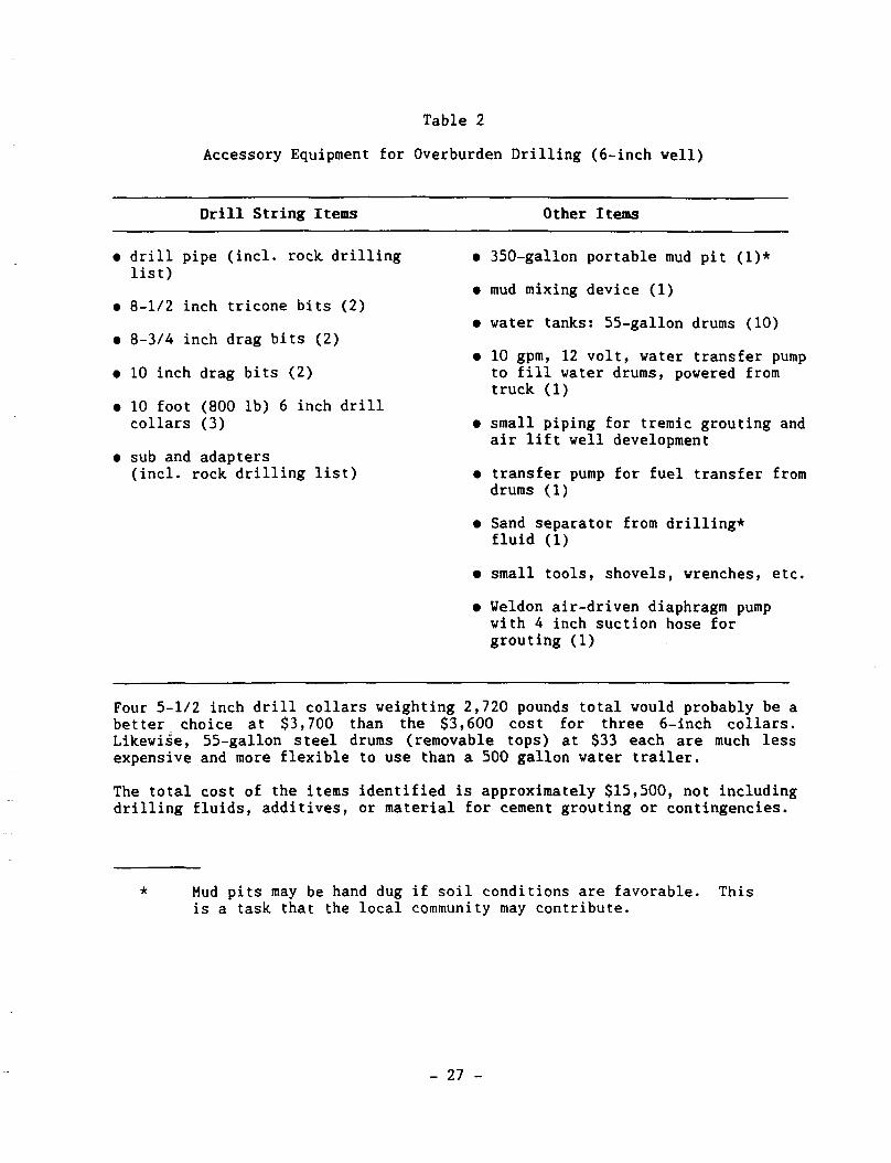
Table 2
Accessory Equipment for Overburden Drilling (6-inch well)
Drill String Items Other Items
• drill pipe (incl. rock drilling list)
• 8-1/2 inch tricone bits (2)
• 8-3/4 inch drag bits (2)
• 10 inch drag bits (2)
• 10 foot (800 lb) 6 inch drill collars (3)
• sub and adapters (incl. rock, drilling list)
• 350-gallon portable mud pit (1)*
• mud mixing device (1)
• water tanks: 55-gallon drums (10)
• 10 gpm, 12 volt, water transfer pump to fill water drums, powered from truck (1)
• small piping for tremic grouting and air lift well development
• transfer pump for fuel transfer from drums (1)
• Sand separator from drilling* fluid (1)
• small tools, shovels, wrenches, etc.
• Weldon air-driven diaphragm pump with A inch suction hose for grouting (1)
Four 5-1/2 inch drill collars weighting 2,720 pounds total would probably be a better choice at $3,700 than the $3,600 cost for three 6-inch collars. Likewise, 55-gallon steel drums (removable tops) at $33 each are much less expensive and more flexible to use than a 500 gallon water trailer.
The total cost of the items identified is approximately $15,500, not including drilling fluids, additives, or material for cement grouting or contingencies.
Mud pits may be hand dug if soil conditions are favorable. This is a task that the local community may contribute.
- 27 -
5.2.2 Accessory Equipment for Air Percussion Drilling
Air percussion drilling would use the same drill pipe, described above, as employed with fluid rotary drilling in overburden formations. As noted in earlier chapters, under certain conditions air percussion drilling might be practiced in overburden drilling but such operations are not normally recommended (see Table 3). Preference for low pressure air, 220 psi or less, and selection of European design hammers for use with bits of under 6 inch (152.4 mm) size was discussed in previous chapters. Bits employed with air percussion drilling are designed with insert buttons. Tools for reshaping these buttons need to be provided to a well crew as reshaping of the buttons will be necessary during the drilling operation. The reshaping tool is a special grinder driven by an air motor and generally sold and serviced by the air percussion bit supplier. The capital cost and weight of the hammer assembly probably dictates that a single unit be taken to the job site with three or more bits. It should be noted that two bits are exactly the same diameter, and care needs to be exercised so that a slightly larger bit is not used after one of slightly smaller size.
Table 3 indicates the basic equipment and quantities to support a drilling operation in the field for up to two years.
5.2.3 Basic Accessories for Overburden Drilling and Air Percussion Rock Drilling with Casings Limited to 4-inch (101.6 mm) Diameter
Tables 4 and 5 list slightly different drilling accessory equipment from that discussed in the previous two subsections if the drilling program is to be limited to the installation of 4-inch (101.6 mm) diameter well casing.
5.3 Miscellaneous Equipment
5.3.1 Water Tanks
The previous subsection identified a need for water tanks and recommended 10 standard 55-gallon (208 liter) drums as the standard equipment. The drums offer the least expensive means for providing water storage even though a small (probably gasoline-powered) engine-driven pump would be necessary for transfer. The drums also offer flexibility since half could be left at the job site while the other half were being filled. An alternative would be a 500 gallon (1,892 liter) water trailer. Volume specifications should be stated as a minimum, since available tanks may be somewhat larger depending on the supplier.
I
- 28 -
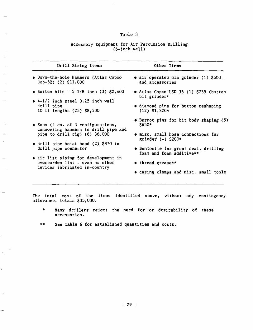
Table 3
Accessory Equipment for Air Percussion Drilling (6-inch well)
Drill String Items Other Items
• Dovn-the-hole hammers (Atlas Copco Cop-52) (2) $11,000
• Button bits - 5-1/8 inch (3) $2,400
• 4-1/2 inch steel 0.25 inch wall drill pipe 10 ft lengths (25) $8,500
• Subs (2 ea. of 3 configurations, connecting hammers to drill pipe and pipe to drill rig) (6) $6,000
• drill pipe hoist hood (2) $870 to drill pipe connector
• air list piping for development in overburden list - swab or other devices fabricated in-country
• air operated dia grinder (1) $500 -and accessories
• Atlas Copco LSD 36 (1) $735 (button bit grinder*
• diamond pins for button reshaping (12) $1,320*
• Borroc pins for bit body shaping (5) $650*
• misc. small hose connections for grinder (-) $200*
• Bentonite for grout seal, drilling foam and foam additive**
• thread grease**
• casing clamps and misc. small tools
The total cost of the items identified above, without any contingency allowance, totals $35,000.
* Many drillers reject the need for or desirability of these accessories.
** See Table 6 for established quantities and costs.
- 29 -
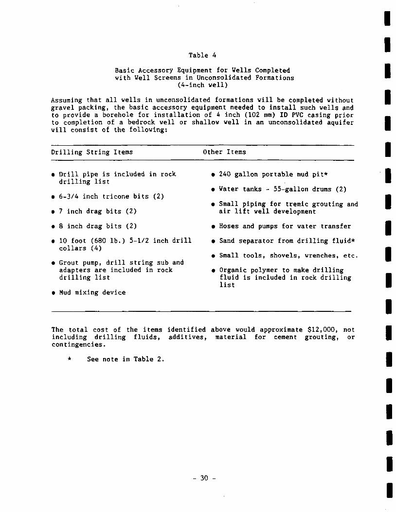
Table 4
Basic Accessory Equipment for Wells Completed with Well Screens in Unconsolidated Formations
(4-inch well)
Assuming that all wells in unconsolidated formations will be completed without gravel packing, the basic accessory equipment needed to install such wells and to provide a borehole for installation of 4 inch (102 mm) ID PVC casing prior to completion of a bedrock well or shallow well in an unconsolidated aquifer will consist of the following:
Drilling String Items Other Items
• Drill pipe is included in rock drilling list
• 6-3/4 inch tricone bits (2)
• 7 inch drag bits (2)
• 8 inch drag bits (2)
• 10 foot (680 lb.) 5-1/2 inch drill collars (4)
• Grout pump, drill string sub and adapters are included in rock drilling list
• Mud mixing device
• 240 gallon portable mud pit*
• Water tanks - 55-gallon drums (2)
• Small piping for tremic grouting and air lift well development
• Hoses and pumps for water transfer
• Sand separator from drilling fluid*
• Small tools, shovels, wrenches, etc.
• Organic polymer to make drilling fluid is included in rock drilling list
The total cost of the items identified above would approximate $12,000, not including drilling fluids, additives, material for cement grouting, or contingencies.
See note in Table 2.
- 30 -
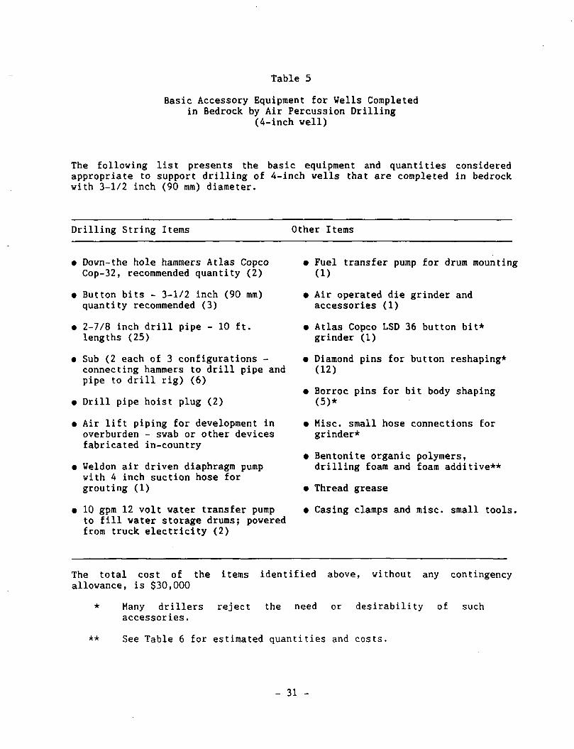
Table 5
Basic Accessory Equipment for Wells Completed in Bedrock by Air Percussion Drilling
(4-inch well)
The following list presents the basic equipment and quantities considered appropriate to support drilling of 4-inch wells that are completed in bedrock with 3-1/2 inch (90 mm) diameter.
Drilling String Items Other Items
• Down-the hole hammers Atlas Copco Cop-32, recommended quantity (2)
• Button bits - 3-1/2 inch (90 mm) quantity recommended (3)
• 2-7/8 inch drill pipe - 10 ft. lengths (25)
• Sub (2 each of 3 configurations -connecting hammers to drill pipe and pipe to drill rig) (6)
• Drill pipe hoist plug (2)
• Air lift piping for development in overburden - swab or other devices fabricated in-country
• Weldon air driven diaphragm pump with 4 inch suction hose for grouting (1)
• 10 gpm 12 volt water transfer pump to fill water storage drums; powered from truck electricity (2)
• Fuel transfer pump for drum mounting (1)
• Air operated die grinder and accessories (1)
• Atlas Copco LSD 36 button bit* grinder (1)
• Diamond pins for button reshaping* (12)
• Borroc pins for bit body shaping (5)*
• Misc. small hose connections for grinder*
• Bentonite organic polymers, drilling foam and foam additive**
• Thread grease
• Casing clamps and misc. small tools.
The total cost of the items identified above, without any contingency allowance, is $30,000
* Many drillers reject the need or desirability of such accessories.
** See Table 6 for estimated quantities and costs.
- 31 -
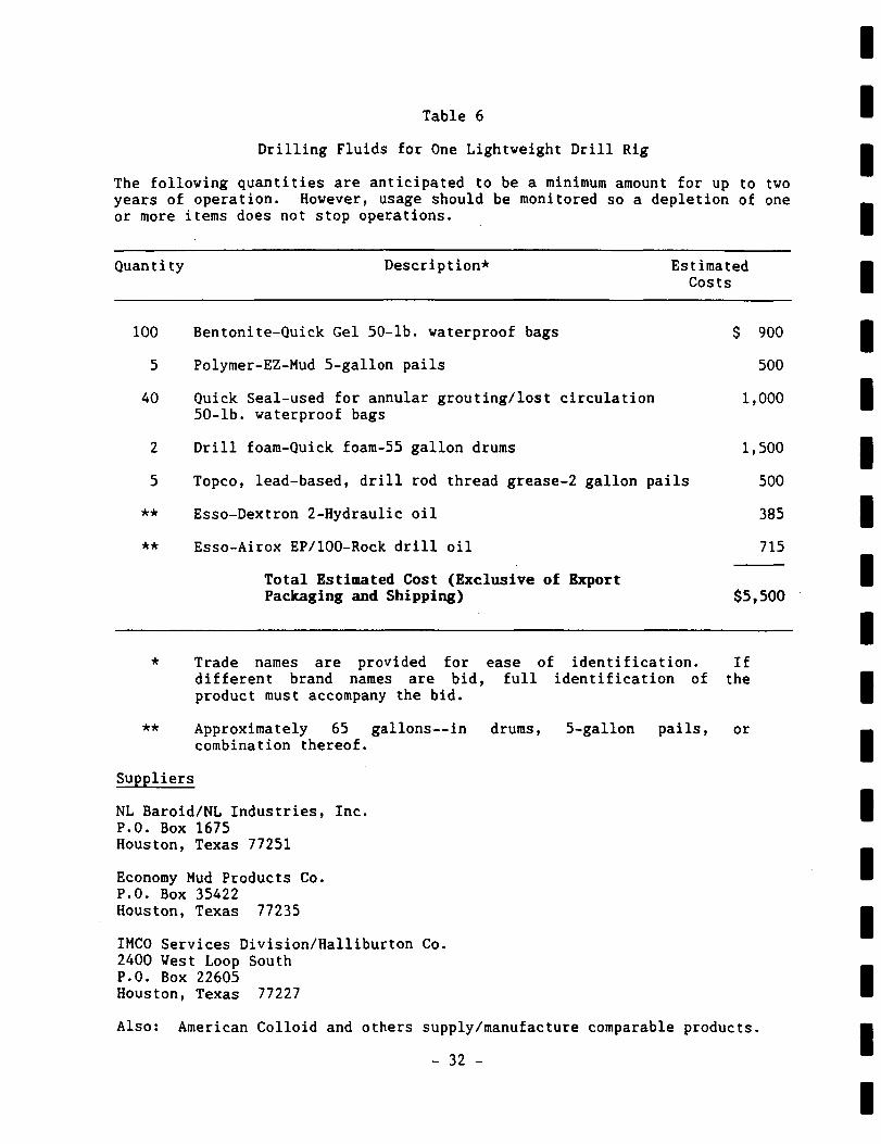
Table 6
$ 900
500
1,000
1,500
500
385
715
Drilling Fluids for One Lightweight Drill Rig
The following quantities are anticipated to be a minimum amount for up to two years of operation. However, usage should be monitored so a depletion of one or more items does not stop operations.
Quantity Description* Estimated Costs
100 Bentonite-Quick Gel 50-lb. waterproof bags
5 Polymer-EZ-Mud 5-gallon pails
40 Quick Seal-used for annular grouting/lost circulation 50-lb. waterproof bags
2 Drill foam-Quick foam-55 gallon drums
5 Topco, lead-based, drill rod thread grease-2 gallon pails
** Esso-Dextron 2-Hydraulic oil
** Esso-Airox EP/100-Rock drill oil
Total Estimated Cost (Exclusive of Export Packaging and Shipping) $5,500
* Trade names are provided for ease of identification. If different brand names are bid, full identification of the product must accompany the bid.
** Approximately 65 gallons—in drums, 5-gallon pails, or combination thereof.
Suppliers
NL Baroid/NL Industries, Inc. P.O. Box 1675 Houston, Texas 77251
Economy Mud Products Co. P.O. Box 35422 Houston, Texas 77235
IMCO Services Division/Halliburton Co. 2400 West Loop South P.O. Box 22605 Houston, Texas 77227
Also: American Colloid and others supply/manufacture comparable products.
- 32 -
5.3.2 Hydrofracturing Equipment
Hydrofracturing has been employed in the oil industry for about 40 years but only recently in the water veil industry. The concept is to increase yields of low-producing water wells in rock by the injection of water under high pressure. Theoretically, a pressure of 200 psi (14.1 kg/cm ) will overcome the weight of overburden material in a 200 ft (61 m) deep hole. However, to actually carry out hydrofracturing, pumps capable of producing 1,000 to 2,000 psi (70.5 to 141 bar) are employed to force open the bedrock fractures. Driscoll states that 800 to 1,000 psi is generally sufficient to fracture formations that are somewhat fractured, but if only a few cracks are present, much higher pressures are necessary.
In the New England states (USA), the operation is undertaken by first lowering an inflatable packer into the bedrock below the casing and then injecting water at 1,000 psi (90.5 bar). One well driller, in the State of Maine (USA), reports achieving 75 percent success in at least doubling production from wells which previously yielded only 1 to 3 gpm (3.8 to 11.3 1pm) with a hydrofracturing pump turning out 60 gpm (378 lps) at 1,200 psi (84.6 bar). In most of these operations the pressure dropped to 500 to 600 psi (35 to 42.3 bar) and held at this level for 15 to 20 minutes. Apparently the duration was a function of the volume of water available.
A Massachusetts (USA) driller reported similar results but suggested that success was a function of the time that was spent in pressurizing. He increased one well from 5 to 25 gpm (18.9 to 94.6 1pm) but had to repeat the operation 4 times.
Kyle Equipment Company of Sterling, Massachusetts, manufactures a 1,000 psi (70.5 bar) model and a second with double this pressure. Both models deliver about 60 gpm (378 lps).
Atlas Copco produces a similar hydrofracturing unit vhich delivers 90 gpm (350 lpm) at 2,000 psi (140 bar). This unit was used by UNICEP crews in Uganda and results almost identical to those achieved in New England were reported. Further description of this equipment is provided in Appendix E.
- 33 -

Chapter 6
COMPARISON OF SELECTED DRILLING RIGS
Tables 6 and 7 compare selected equipment which might be considered for rural well drilling programs. The list of drilling units is not meant to be exhaustive but rather exemplifies a process of comparison between the units. All of the rigs are trailer-mounted.
Beginning with the basic premise that at least 1,600 ft lb torque is a requirement to operate drag bits in overburden drilling, the Deep Rock, rigs do not meet this criterion. Other problems with this equipment have been identified by many in the field, but it has met with acceptance by several PVO organizations in the past due to the low cost of previously offered models. The Remaire model does include a deck-mounted air compressor operated by a separate 112 HP engine, but deck space is so tight that mounting a centrifugal mud pump is not possible and no provision is made for a high-speed auxiliary winch. Such a winch is desirable for bailer cleaning, development procedures, and testing capacity of completed wells.
The Canterra offering does meet a 1,600 ft lb torque minimum, but barely. This unit also includes a deck-mounted air compressor in a model which exceeds both minimum output and pressure requirements. Mud pump output is less than desirable and it lacks an auxiliary winch. The manufacturer and model of water pump and hammer oiler are omitted from the literature but could be provided if requested by purchasers, according to verbal discussion with Canterra. This unit includes many U.S. components but is fabricated in Canada. A U.S. office is maintained but it has not fully explored whether it could meet U.S. AID procurement requirements.
Problems of weight are present with both the Failing and Mobile equipment to meet the criteria expressed in previous chapters.
Weight is a major consideration in selecting equipment for a rural well drilling program. Sometimes there is no alternative to specifying a rig with weight in excess of that needed for servicing most rural communities. For example, Mobile B-80s were chosen for Bolivia where depth and other matters dictated such equipment. Even the Canterra CT-211s, mounted on Ford F-700s, have been described as bridge-cracking units and these units are lighter than the Mobile B-80 unit.
- 35 -
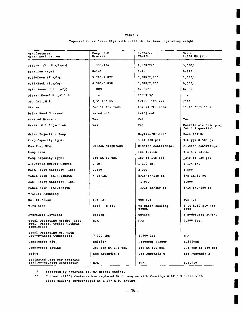
Table 7
Top-head Drive Drill Rigs with 7,500 lb, or less, operating weight
Manufacturer Model Designation
Torque (ft. lbs/kg-m)
Rotation (rpm)
Pull-Down (lbs/kg)
Pull-Back (lbs/kg)
Main Power Unit (rafg)
Diesel Model No./C.I.D.
No. Cyl./H.P.
Stroke
Drive Head Movement
Powered Breakout
Hammer Oil Injection
Water Injection Pump
Pump Capacity (gpra)
Mud Pump Mfg.
Pump size
Pump Capacity (gpm)
Air/Fluid Swivel Course
Main Hoist Capacity (lbs)
Cable Diam (in.(/length
Aux. Hoist Capacity (lbs)
Cable Diam (in)/length
Trailer Mounting
No. of Axles
Tire Size
Hydraulic Leveling
Total Operating Weight (less fuel, water, tools) without compressor
Total Operating Wt. with Deck-mounted Compressor
Compressor mfg.
Compressor rating
Price
Estimated Cost for separate trailer-mounted compressor.
Deep Rock Ramaire
1,333/184
0-140
5,700-2,872
8,500/3,850
MWM
-
3/51 (38 kw)
for 10 ft. rods
swing out
Yes
Yes
Weldon-diaphragm
240 at 60 psi
2-in.
2,500
5/16-in/-
-
-
two (2)
8x15 - 8 ply
Option
N/A
7,000 lbs
Sulair*
350 cfm at 175 psi
See Appendix F
N/A
Canterra CT-371
1,620/220
0-95
6,000/2,700
6,000/2,700
Deutz»»
Br6L913/
6/165 (123 kw)
for 10 ft. rods
swing out
Yes
Yes
Boyles-"Bronco"
4 at 250 psi
Mission-centrifugal
lxl-l/2-in
180 at 145 psi
1-1/2-in.
2,300
5/16-in/120 ft
1,000
3/16-in/250 ft
two (2)
to match hauling truck
Option
N/A
5,600 lbs
Rotocomp (Bauer)
450 at 190 psi
See Appendix O
N/A
Simco 2,800 HS (HT)
3,500/
0-120
6,500/
6,500/
Deutz
-
/100
11.08 ft/3.38 m
Yes
Manzell electric pump for 0-2 quarts/hr.
Bean A0410c
0-8 gpm 9 500 psi
Mission-centrifugal
3 x 4 x 13-in.
+340 at 120 psi
1-1/4-in.
3,500
3/8 in/80 ft
1,000
3/16-in./500 ft
two (2)
8-14.5/12 ply (F) rate
3 hydraulic 24-in.
7,500 lbs.
N/A
Sullivan
375 cfm at 150 psi
See Appendix H
$26,000
operated by separata 112 HP diesel engine.
Current (1988) Canterra has replaced Deutz engine with Cummings 6 BT 5.9 liter with
after-cooling turbocharged at a 177 H.P. rating.
- 36 -
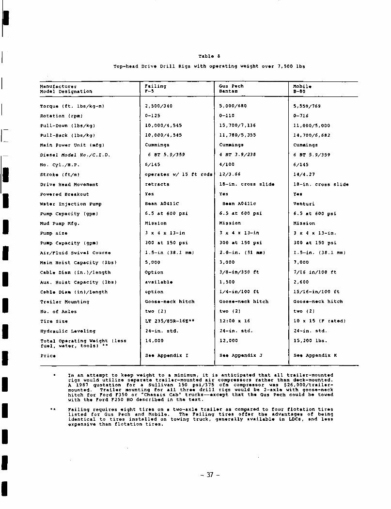
Table 8
Top-head Drive Drill Rigs with operating weight over 7,500 lbs
Manufacturer Model Designation
Torque (ft. lbs/kg-m)
Rotation (rpm)
Pull-Down (lbs/kg)
Pull-Back (lbs/kg)
Main Power Unit (mfg)
Diesel Model No./OLD.
No. Cyl./H.P.
Stroke (ft/ra)
Drive Head Movement
Powered Breakout
Water Injection Pump
Pump Capacity (gpo)
Mud Pump Mfg.
Pump size
Pump Capacity (gpm)
Air/Fluid Swivel Course
Main Hoist Capacity (lbs)
Cable Diam (in.(/length
Aux. Hoist Capacity (lbs)
Cable Diam (in(/length
Trailer Mounting
No. of Axles
Tire Size
Hydraulic Leveling
Total Operating Weight (less fuel, water, tools) **
Price
Failing F-5
2,500/340
0-125
10,000/4,545
10,000/4,545
Cummings
6 8T 5.9/359
6/14 5
operates w/ 15 ft rods
retracts
Yes
Bean A0411C
6.5 at 600 psi
Mission
3 x 4 x 13-in
300 at 150 psi
1.5-in (38.1 mm)
5,000
Option
available
option
Goose-neck hitch
two (2)
LT 235/85R-16E**
24-in. std.
14,000
See Appendix I
Gus Pech Bantam
5,000/680
0-110
15,700/7,136
11,780/5,355
Cummings
4 BT 3.9/238
4/100
12/3.66
18-in. cross slide
Yes
Bean A0411c
6.5 at 600 psi
Mission
3 x 4 x 13-in
300 at 150 psi
2.0-in. (51 mm)
3,000
3/8-in/350 ft
1,500
l/4-in/100 ft
Goose-neck hitch
two (2)
12:00 x 16
24-in. std.
12,000
See Appendix J
Mobile B-80
5,559/769
0-716
11,000/5,000
14,700/6,682
Cummings
6 BT 5.9/359
6/145
14/4.27
18-in. cross slide
Yes
Venturi
6.5 at 600 psi
Mission
3 x 4 x 13-in.
300 at 150 psi
1.5-in. (38.1 mm)
7,000
7/16 in/100 ft
2,600
15/16-in/100 ft
Goose-neck hitch
two (2)
10 x 15 (F rated)
24-in. std.
15,200 lbs.
See Appendix K
In an attempt to keep weight to a minimum, it is anticipated that all trailer-mounted rigs would utilize separate trailer-mounted air compressors rather than deck-mounted. A 1987 quotation for a Sullivan 150 psi/375 cfm compressor was $26,000/trailer-mounted. Trailer mounting for all three drill rigs would be 2-axle with goose-neck hitch for Ford F350 or "Chassis Cab" trucks—except that the Gus Pech could be towed with the Ford F250 HO described in the text.
Failing requires eight tires on a two-axle trailer as compared to four flotation tires listed for Gus Pech and Mobile. The Failing tires offer the advantages of being identical to tires installed on towing truck, generally available in LDCs, and less expensive than flotation tires.
- 37 -
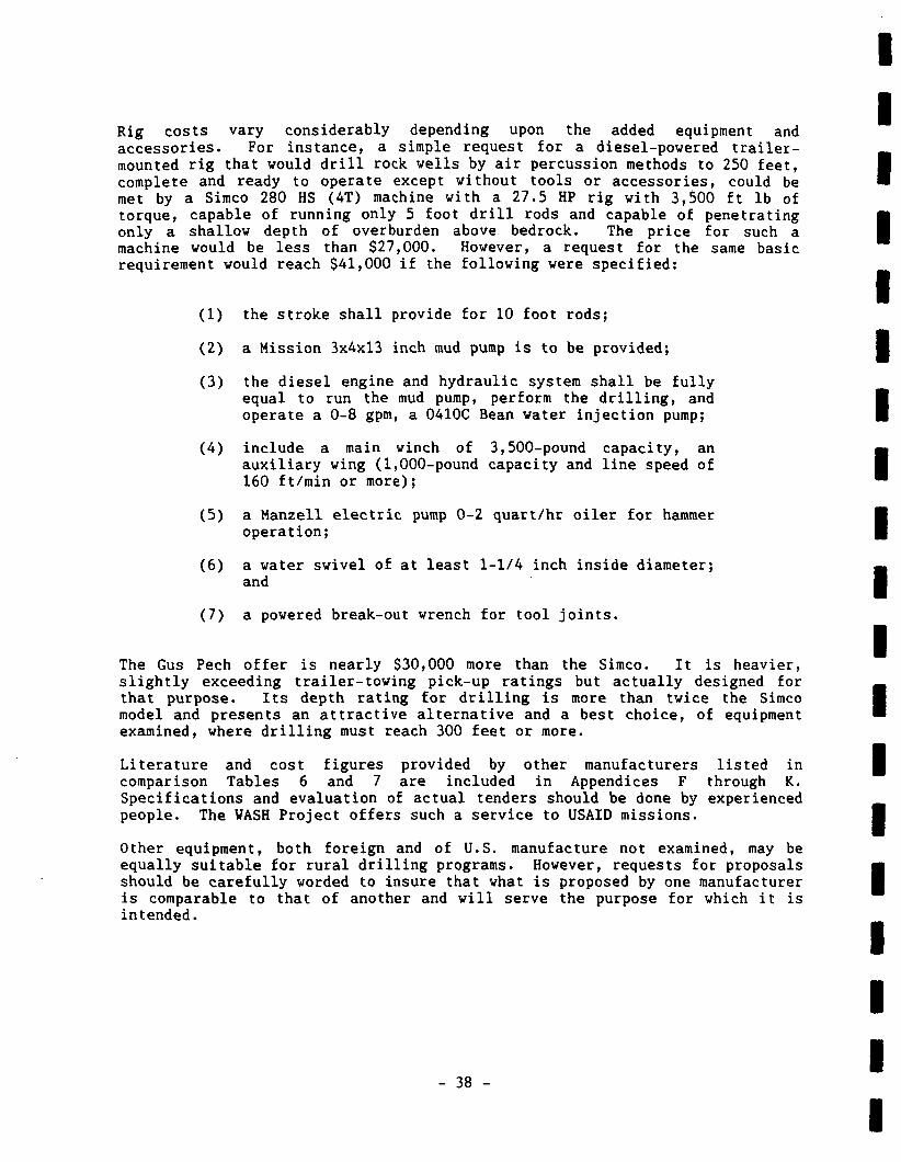
Rig costs vary considerably depending upon the added equipment and accessories. For instance, a simple request for a diesel-powered trailer-mounted rig that would drill rock veils by air percussion methods to 250 feet, complete and ready to operate except without tools or accessories, could be met by a Simco 280 HS (4T) machine with a 27.5 HP rig with 3,500 ft lb of torque, capable of running only 5 foot drill rods and capable of penetrating only a shallow depth of overburden above bedrock. The price for such a machine would be less than $27,000. However, a request for the same basic requirement would reach $41,000 if the following were specified:
(1) the stroke shall provide for 10 foot rods;
(2) a Mission 3x4x13 inch mud pump is to be provided;
(3) the diesel engine and hydraulic system shall be fully equal to run the mud pump, perform the drilling, and operate a 0-8 gpm, a 0410C Bean water injection pump;
(4) include a main winch of 3,500-pound capacity, an auxiliary wing (1,000-pound capacity and line speed of 160 ft/min or more);
(5) a Manzell electric pump 0-2 quart/hr oiler for hammer operation;
(6) a water swivel of at least 1-1/4 inch inside diameter; and
(7) a powered break-out wrench for tool joints.
The Gus Pech offer is nearly $30,000 more than the Simco. It is heavier, slightly exceeding trailer-towing pick-up ratings but actually designed for that purpose. Its depth rating for drilling is more than twice the Simco model and presents an attractive alternative and a best choice, of equipment examined, where drilling must reach 300 feet or more.
Literature and cost figures provided by other manufacturers listed in comparison Tables 6 and 7 are included in Appendices F through K. Specifications and evaluation of actual tenders should be done by experienced people. The WASH Project offers such a service to USAID missions.
Other equipment, both foreign and of U.S. manufacture not examined, may be equally suitable for rural drilling programs. However, requests for proposals should be carefully worded to insure that what is proposed by one manufacturer is comparable to that of another and will serve the purpose for which it is intended.
- 38 -
Chapter 7
TRAINING
7.1 Formal Driller Training
A recent check of institutions that formerly provided education in water-well technology revealed that all of the U.S. institutions have dropped this curriculum. The National Water Well Association's catalog (April 1981) of institutions is attached in Appendix L.
J. Sargent Reynolds Community College, Richmond, Virginia, has provided special short-term, 10-week courses for USAID in recent years designed to provide foreign well drillers with some basic concepts in both groundwater hydrology and certain drilling techniques.
The Sir Sanford Fleming Program, in Ontario, Canada, is still offered. This program was and is generally recognized as the best preparation for a drilling career that one can obtain in the time encompassed in the program.
7.2 In-Country Supervision and Training
While many drilling programs are operating successfully in developing countries using local drillers, many other countries lack an adequate supply of trained drillers and rig mechanics. The maintenance of drill rigs is a particularly significant problem. Examples abound of drill rigs which have been scrapped after only a few years of operation in many developing countries. Improper or less than optimum operation standards have led to poorly constructed wells and equipment with short life spans.
Specialized training in rig repair will be needed in most drilling projects. Drill rigs are sufficiently complex that considerable attention needs to be paid to assuring rig maintenance and repair by competent mechanics. On-the-job training is appropriate in many drilling programs although project objectives must be clear as to whether the project is production oriented, training oriented, or a combination of the two.
Training services are generally accomplished more efficiently through a service contract with an experienced firm in the drilling business. Contracts to purchase drill rigs should contain provisions for factory representatives to provide specified training during the start-up operations of the rig and periodically thereafter. In many instances, operations and repair manuals will need to be translated into local languages. Short-term training experts may also be needed in hydrogeology for locating drilling sites, geophysical instrumentation, uses of fluid additives, inventory and warehousing hammer repair, bit sharpening, casing and screen fabrication, and a variety of other specialties.
- 39 -

Chapter 8
CONCLUSIONS
It is the premise of this report that developing countries should rely upon smaller drill rigs for their rural water supply programs than generally used in the past. Light-weight drill rigs have recently been developed which meet the technical requirements of most rural water supply programs. Significant savings in the purchase price and operating expenses of the smaller drill rigs can be expected. Such savings are critical in finding low-cost means to provide water supplies to the large number of rural inhabitants who presently lack clean and accessible water. This report has discussed considerations which are important in drill rig selection. A checklist of these considerations is provided in Table 8.
While this report focuses on technical considerations, these are by no means the only factors in undertaking a rural water supply program. The institutional, community, and human elements of rural water supply are of central importance and must be considered.
The management of drilling operations typically includes a combination of institutional arrangements. In some cases relatively more responsibility is given to non-governmental organizations (engineering firms, PVOs, etc.) while in other instances the government agencies retain overall responsibility with outside organizations acting as advisors. In recent years, government agencies have successfully contracted with private companies for specific phases of operations, particularly drilling operations; this has become common in several countries. Whichever form of management is adopted, adequate back-up for drilling operations must be assured. This includes such diverse but critical items as community organization, hydrogeological siting, fuel supplies, spare parts supplies, support vehicles, and many others. Unless these components are assured in quantities and timing to match the potential high production rates of modern drill rigs, there is little value in investing in such rigs.
A particularly important example of how institutional and management approaches affect drill rig production is found in the remuneration of drilling crews. Crews of these rigs often work under arduous conditions in remote locations and for extended periods of time. Crews on straight salaries have been found in many instances not to have adapted to the potentially increased production of fast drill rigs. Wage incentives based on production have been found appropriate to enhance efficient operation of the drilling program.
At the village level, it is necessary to involve the community in all phases of the program, from design through construction, and finally the continued operation and maintenance procedures. Successful programs usually require primary responsibility for operation and maintenance to remain with the village itself. The procedures and responsibilities for O&M should be thoroughly worked out and understood by all parties before the drilling operations begin. Procedures and considerations for community participation in water and sanitation projects are available in other WASH reports.
- 41 -
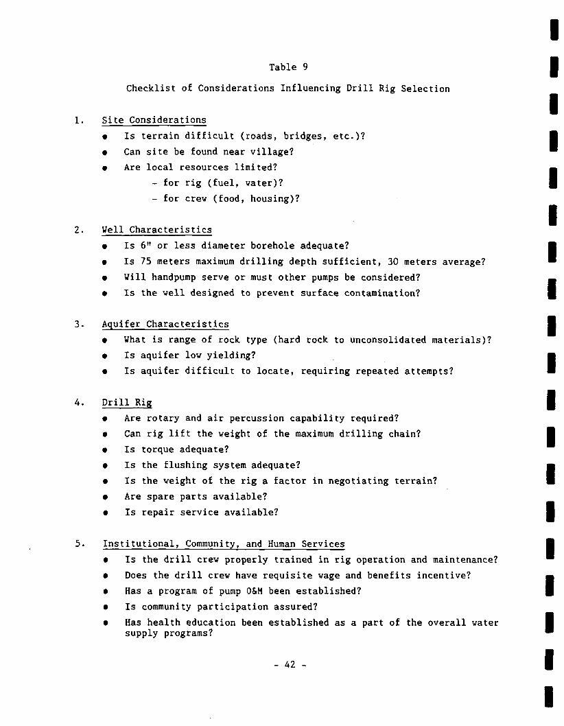
Table 9
Checklist of Considerations Influencing Drill Rig Selection
Site Considerations
• Is terrain difficult (roads, bridges, etc.)?
t Can site be found near village?
• Are local resources limited?
- for rig (fuel, water)?
- for crew (food, housing)?
Veil Characteristics
• Is 6" or less diameter borehole adequate?
• Is 75 meters maximum drilling depth sufficient, 30 meters average?
• Will handpump serve or must other pumps be considered?
• Is the well designed to prevent surface contamination?
Aquifer Characteristics
• What is range of rock type (hard rock to unconsolidated materials)?
• Is aquifer low yielding?
• Is aquifer difficult to locate, requiring repeated attempts?
Drill Rig
• Are rotary and air percussion capability required?
• Can rig lift the weight of the maximum drilling chain?
• Is torque adequate?
• Is the flushing system adequate?
• Is the weight of the rig a factor in negotiating terrain?
• Are spare parts available?
• Is repair service available?
Institutional, Community, and Human Services
• Is the drill crew properly trained in rig operation and maintenance?
• Does the drill crew have requisite wage and benefits incentive?
• Has a program of pump 0&M been established?
• Is community participation assured?
• Has health education been established as a part of the overall water supply programs?
- 42 -
Finally, it should be noted that the ultimate objective of a rural water supply program is to contribute to the improved health of the villagers. The provision of water alone is seldom sufficient. Water supply programs should also include a coordinated program of health and hygiene education. Approaches to incorporating hygiene education with water supply projects are also available in WASH reports. Through programs of providing water wells via low-cost drilling operations and integrating hygiene education into the process, improved health for rural inhabitants can be expected.
- 43 -


BIBLIOGRAPHY
- A5 -

BIBLIOGRAPHY
1. Ahmed, N. 1969. Tubewells Construction and Maintenance. Scientific Research Stores, 4 Abkari Road, Lahore, Pakistan
2. Aherns, T. D. 1957. "Well Design Criteria," Water Well Journal. Vol. II. Nos. 9 and 11, Sept. and Nov.
3. . 1970. "Basic Consideration of Well Design," Water Well Journal. April p. 45-50, May p. 49-51, June p. 48-51, August 35-37.
4. American Water Works Association. 1984. A.W.W.A. Standard for Deep Wells. A.W.W.A. A100-84, A.W.W.A. Denver, CO
5. Appleton, B. 1983. "Are Drilling Tenders Rigged?" World Water. April.
6. . 1983. "Choosing a Drilling Rig: the UNICEF Process Explained." World Water. May.
7. . 1983. "Manufacturers Bring Back Smaller Machines as Focus Moves to Village Supplies." World Water. July.
8. Arlosoroff, S. et al. 1987. Community Water Supply: The Handpump Option. Washington, D.C.: World Bank.
9. Blankwaart, B. 1984. Hand Drilled Wells. Rwegarulila Water Resource Institute, Dares Salaam^ Tanzania - Distribution by: TOOL Foundation, Entrepotdok 68A/69A 1018 AD Amsterdam, Netherlands
10. Bush, R. E. 1978. Well Construction - Hand Dug Hand Drilled. Washington, D.C.: U.S. Peace Corps.
11. Campbell, M. D. and J. H. Lehr. 1973. Water Well Technology. Nev York: McGraw-Hill.
12. Davis, S. N. and Turk. 1969. "Best Well Depths in Crystalline Rocks," Ground Water, Vol. 2, No. 2, April, p. 6-11.
13. Driscoll, F. G. 1986. Groundwater and Wells - Second Ed. St. Paul, MN: Johnson Division.
14. Gibson, U. P. and R. D. Singer. 1971. Water Well Manual. Agency for International Development (Small Wells Manual - 1969), Premier Press.
15. Higgins, B. 1986. "Frontier for Rural Survival." World Water. November.
16. Larsson, I., Ground Water in Hard Rocks, UNESCO - Studies and reports in hydrology 33, UNESCO.
17. LeGrand, H. E., Ground Water in the Piedmont and Blue Ridge Provinces in the Southeastern States. U.S. Geological Survey - Circular 538, U.S. Govt. Printing Office.
- 47 -
18. Preble, R. E. 1974. The Effect of Drought Conditions upon Village Water Supply and Public Health in Mauritania. WASH Field Report No. 112.
19. 1984. Helping Ghana Search for Water. WASH Field Report No. 132
20. Preble R. E., and E. Rumph. 1984. An Assessment of Problems and Needs for Water Supplies at Ethiopian Drought Victim Camps. WASH Field Report No. 138.
21. Preble, R. E., and P. Stevens. 1985. Ouagadougou's Water Supply and Water Supplies for Displaced Persons in Burkina Faso. WASH Field Report No. 144.
22. Roark, Philip et al. 1986. Final Evaluation: USAID/Burkina Faso Rural Water Supply Project. WASH Field Report No. 191.
23. 1987. Privatization Study of the Village Water Supply and Sanitation Proje'ct—Lesotho. WASH Field Report No. 215.
24. . 1988. Final Evaluation of the USAID/Togo Rural Water Supply and Sanitation PRoject. WASH Field Report No. 228.
25. St. Michel, L. A., and R. E. Preble. 1986. Rural Water Supply and Emergency Needs in Uganda. WASH Field Report No. 189.
26. Sayre, A. N. and G. C. Taylor. 1951. Ground Water Resources of the Republic of El Salvador. U.S. Geological Survey - Water Supply Paper 1079-D, U.S. Govt. Printing Office.
27. Sternberg, Y,. M. and R. Knight. 1980. Final Report on Broached Roboscreen. AID/DSE-C-0038.
28. Turner, W. 1984. Evaluation of Well Drilling Equipment for Bolivia Rural Water Supply and Sanitation Program. WASH Field Report No. 116.
29. U.S. Bureau of Reclamation. 1977. Ground Water Manual. U.S. Govt. Printing Office.
30. U.S. Environmental Protection Agency. 1975. Manual of Water Well Construction Practices. EPA-570/9/75/001, Washington, DC: Office of Water Supply.
31. Vozdvizhensky, R., 0. Golubintseu and A. Novozhilov. 1982 English Ed., Exploratory Drilling. Mir Publishers, USSR 129820, Moscow, 1-110, GSP, Pervy Rishsky Pereulok 2.
32. Watt, S. G. and W. E. Wood. 1977. Hand-dug Wells and Their Construction. Intermediate Technology Group, 9 King St., London, WCZE8HW, England.
33. ZaKula, V.S. 1985. Guidelines for Drillers, Engineers, Geologists and Drilling Trainees. UNICEF, Addis Ababa, Ethiopia.
- 48 -
APPENDIX A
Ground Water in Hard Rocks
- 49 -

Ground water in hard rocks
Project 8.6 of the International Hydrologjcal Programme
Prepared by the Project Panel, Ingemar Larsson: Chairman
Unesco
51
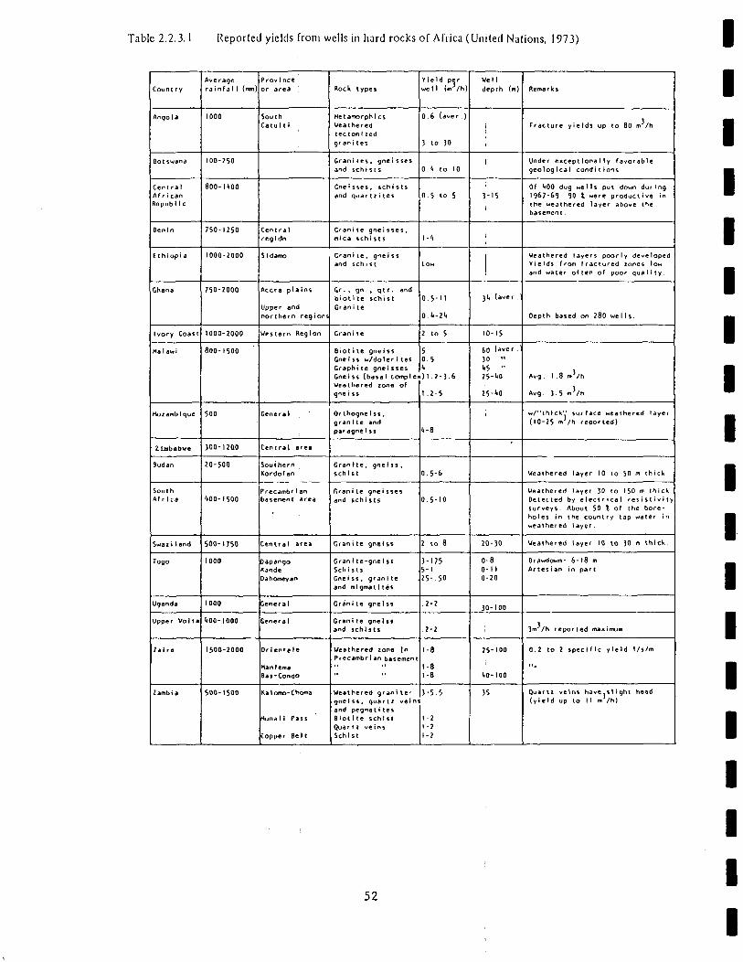
Table 2.2.3.1 Reported yields from wells in hard rocks of Africa (United Nations, 1973)
Count ry
Angola
Bot swana
Cent ra I
Mr i can
Bepubl Ic
Benin
E t h1 op I a
Ghana
Ivory Coast
Ha 1aw>
Hozamb1 que
Zimbabwe
Sudan
South
Africa
Swaii1 and
Togo
Uganda
Upper Volt a
?ai re
iambi a
Average
rainfa 1 1 (mm)
1000
100-250
8 0 0 - U O O
750-1250
1000-2000
750-2000
1000-2000
800-1500
500
3Q0-12Q0
20-500
400-1500
500-1750
1000
1000
1*00-1000
1500-2000
500-1500
Province
or area
South
Catulti
Central
regldn
S1damo
Accra plains
Upper and
northern regions
Western Reg ton
General
Cent ral area
Southern
Kordofan
PrecambcI an basement area
Central area
Dapango
Kande
Dahomeyan
General
General
Or ien'ele
Hanlema Baj-Conflo
Ka 1 omo-Choft»a
Munall Pass
Copper Belt
Rock types
Hetamorphics
Weathered
tec tont zed
grani tes
Grani(es , gne i sses
and schists
Gne i sses , sch i sts
and quar11i tes
Gran i te gnelsses,
mica schi s ts
Grani te, gne i ss
and schist
Gr . , gn. , qtr. and
biotite schist
Grani te
Grani te
Biot1te gnei ss
Gnel ss w/doler i tes
Graphite gnei sses
Gneiss (basal complex
Weathered zone of
gne t ss
Or thogne i ss .
granite and
paragnelss
Gran rte , gne1ss ,
schist
f.ran i te gnei sses
and schists
Granite gnelss
Gran 1te-gneIss
Schists
Gne i ss , gran 1te
ami mlgntat i t es
Grani te gneiss
Grani te gneIss
and schists
Weathered zone \n Precambrian basement
Weathered granite-
gnelss, quartz veins
and pegmat i tes
Blot 1te schist
Quar 11 ve ins Schist
Yield per
well (fliVh)
0.6 (aver.)
3 to 30
0.4 to 10
0.5 to 5
• - <•
Low
0.5-M
O.it-2'i
2 to 5
5
0.5
<• )1.2-3.6
1.2-5
l l - 8
0.5-6
0.5-10
2 to 8
3-175
5-1
2 5 - 5 0
.2-2
2-2
1-8
1-8
1-8
3-55
1-2
1-2
1-2
Well
depth (m)
i
1
3-15
i
i
3I1 (aver .)
10-15
(,0 (aver .)
30 "
1,5 ..
25-<iO
25-W
1
20-30
0-8 0-11 0-20
30-100
;
2 5 - 1 0 0
liO-lOO
35
Remarks
Fracture yields up to 80 m /h
Under exceptionally favorable
geological conditions
Of f»00 dug wells put down during
1967-69 90 X were productive in
the weathered layer above the
basement.
Weathered layers poorly developed
Yields from fractured zones low
and water often of poor quality.
Depth based on 280 wells.
Avg. 1.8 m'/h
Avg. 3 5 m 7 h
w/"thlck" surface weathered layer
(10-25 m /h reported)
Weathered layer 10 to 50 m thick
Weathered layer 30 to 150 m thick.
Detected by electrical resistivity
surveys. About 50 % of the bore
holes in the country tap water in
weathered layer.
Weathered layer 10 to 30 m thick.
Drawdown: 6-18 m
Artesian in part
3m /h reported maximum
0.2 to 2 specific yield l/s/m
Quartz veins have slight head
(yield up to II m /hi
52
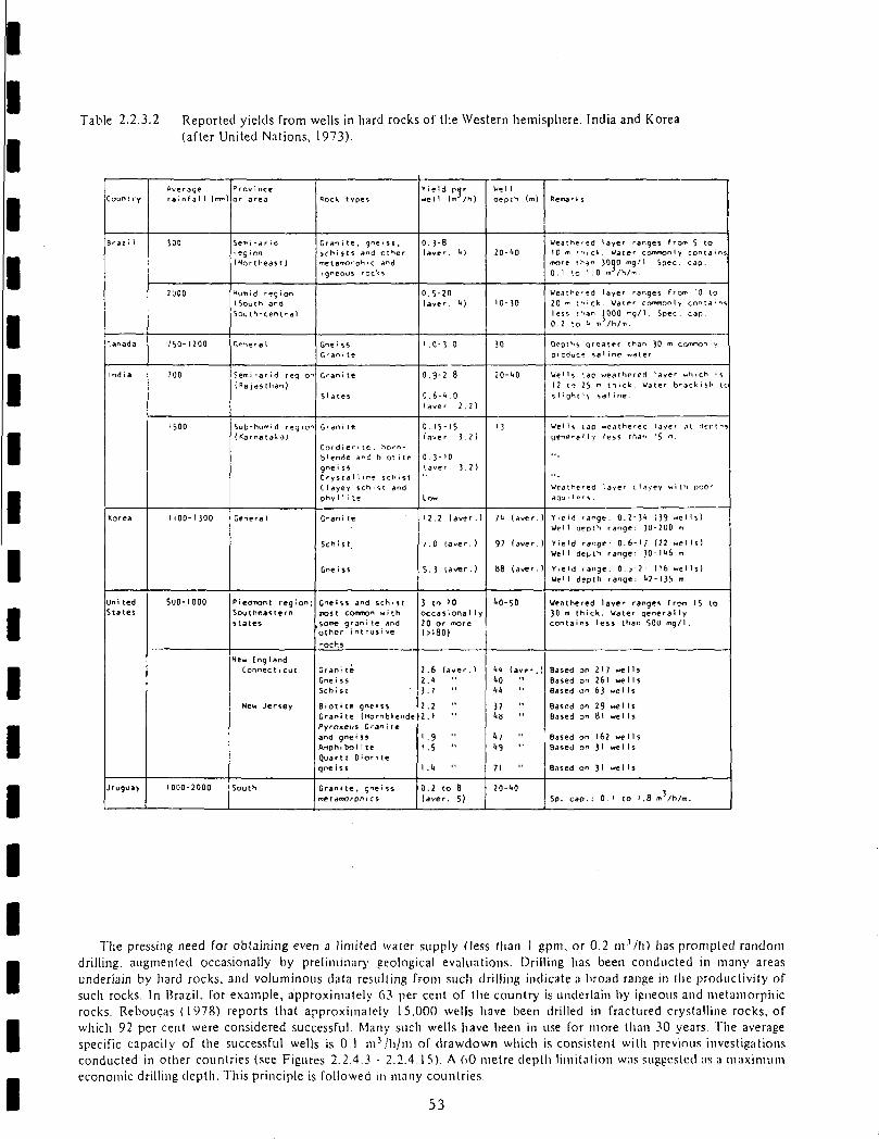
Table 2.2.3.2 Reported yields from wells in hard rocks of the Western hemisphere. India and Korea (after United Nations, 1973).
Count ry
Braz i 1
Canada
India
Korea
Uni ted
States
Uruguay
Average
rainfal 1 (mm)
300
2000
750- W O O
700
1500
I 100-MOO
5U0-IOOO
1000-2000
Province
or area
Semi-arid
ieg ion
(Northeast)
Hum! d reg i on
(South and
Sou th-cent ral
Gene ra 1
Semi-arid req ion
(Rajas than)
Sub-humi d reg i on
(Karnatak-3)
General
P iedmont region;
Southeastern
states
New England
Connec 11cut
New Jersey
South
Rock types
Grant te , gne iss,
scni sts a^d ot Her
me t a m e phi c a"d
i gneoUS roc'<S
Gne rS5
Grani te
Grani te
Slates
Gran i te
Cordi ei-itc. horn
blende ani bi ot i te
gne ts5
Crystal 1 r n * S C h i S t
C1ayey sen . s t and
phy1 1 i te
Grant te
Schist.
Gne iss
Gneiss and schi st
TOSt COfffnon with
some grani te and other i nt rus i ve
rocks
Grani te
Gneiss
Schist
Biot•te gnei ss
Grani te (Hornblende
Pyr-oxeus Granite
and gnei ss
Amphi boli te
Quartz Oiori te
gne i ss
Grani te, gne'ss
meiamorphics
Yield per
well (m-Vh)
0. 3-8 (aver U)
0.5-20
iav^r. <*)
l .0-3-0
0.9-2.8
0.6-1*.0 (aver 2.2)
0.15-15 (aver. 3-2)
0.3-10
(aver. 3-2)
Low
12.2 (aver.)
/.0 laver.)
5.3 (av*r.)
3 to 10
occasiona1 1 y
20 or more
(>180)
2.6 (aver.)
2.<*
3.1
2.2
2.1
1 .9 "
1.5 M
l.l* "
0.2 to 8
laver. 5)
wei 1
aepth (m)
20-(*0
10-30
30
20-1*0
'3
?<* (aver.)
97 faver.)
tt8 (aver.)
1*0-50
<*<* (aver.)
1*0 "
37 " l*H "
w ••
1*9 "
71
20-t*0
Remarks
Weathered layer ranges from 5 to
J 0 m rhicW. Water commonly contains
more t?~an 3000 mg/1 Spec. cap.
0.1 »c 1.0 m3/h/m.
Weatr>ered layer ranges from 10 to
20 m thick. Water commonly conta-ns
less than 1000 mg/1. Spec. cap.
0.2 10 ** m /h/m.
Depths Qreater than 30 m commonly
produce saline water.
We'' s '.ao weathered layer which ;s
12 to 25 m thick. Water brackish ic
s 1 ;ght »y sal ine .
Wells tap weathered layer at derths
qenera'fy less than 15 m-
Weathered layer clayey with poor
aqui f ers .
Y i c M range: 0.2-3^ (39 wcl Is)
Well depth range: 30-200 m
Yield range: 0.6-1; (22 welIs)
Well dei,tn range: 30 -1 **6 m
Yield range: 0.5-21 (lb wclIs)
Well depth range: 1*2-135 m
Weathered layer- range* from 15 to
30 m thick. Water qenerally
contains less than 500 mg/1.
Based on 217 we 11s
Based on 26l we 11s
Based on 63 welIs
Based on 29 we 11s
Based on 81 wells
Based on 162 we 11s
Based on 31 we 11s
Based on 31 we 1 1 s
Sp. cap.: 0 ' to 1.8 m /h/m.
The pressing need for obtaining even a limited water supply (less than I gpm, or 0.2 inVli) has prompted random drilling, augmented occasionally by preliminary geological evaluations. Drilling has been conducted in many areas underlain by hard rocks, and voluminous data resulting from such drilling indicate a broad range in the productivity of such rocks. In Brazil, for example, approximately 63 per cent of the country is underlain by igneous and metamorphic rocks. Reboucas (1978) reports that approximately 15.000 wells have been drilled in fractured crystalline rocks, of which 92 per cent were considered successful. Many such wells have been in use for more than 30 years. The average specific capacity of the successful wells is 0.1 m3/h/m of drawdown which is consistent with previous investigations conducted in other countries (see Figures 2.2.4.3 - 2.2.4.1 5). A 60 metre depth limitation was suggested as a maximum economic drilling depth. This principle is followed in many countries.
53

APPENDIX B
Support Vehicle for Drill Rig Crew
- 55

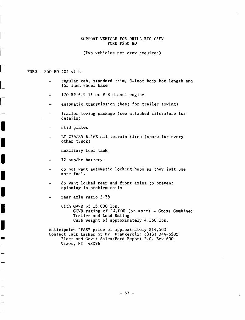
SUPPORT VEHICLE FOR DRILL RIG CREW FORD F250 HD
(Two vehicles per crew required)
FORD - 250 HD 4X4 with
regular cab, standard trim, 8-foot body box length and 155-inch wheel base
170 HP 6.9 liter V-8 diesel engine
automatic transmission (best for trailer towing)
trailer towing package (see attached literature for details)
skid plates
LT 235/85 R-16E all-terrain tires (spare for every other truck)
auxiliary fuel tank
72 amp/hr battery
do not want automatic locking hubs as they just use more fuel.
do want locked rear and front axles to prevent spinning in problem soils
rear axle ratio 3.55
with GVWR of 15,000 lbs. GCWR rating of 14,000 (or more) - Gross Combined Trailer and Load Rating Curb weight of approximately 4,350 lbs.
Anticipated "FAS" price of approximately $14,500 Contact Jack Lasher or Mr. Frankeroli: (313) 344-6285
Fleet and Gov't Sales/Ford Export P.O. Box 600 Wixom, MI 48096
- 57 -
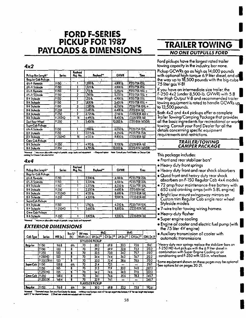
FORD F-SERIES PICKUP FOR 1987
PAYLOADS & DIMENSIONS
4x2
TRAILER TOWING NO ONE OUTPULLS FORD
Pickup Bo» Length* Regulor Cob Pickup! 6 M t Floreside 6V.-ft StyJetide lYi-k floreside 6V«-h Stylciide 8-ft Styleside 8-ft.Stytttide 8-fi Styteside 8-ftSfyleside e-ftSM^de 8-ftStyleside DuolReor Wheel SuperCob Pickups 6V«-fc Stytetide 8-ft StyJeside 8-ft Stykwide
Series
F-150 F-150 f-150 F-150 F-150 F-150 F-150 F-250 F-250 F-250HD F-350
F-150 F-150 F-250HD
Payload Pkg.No.
IX
IX
Poylood"
1,3001b. 1,325 b. 1715 b 1,740 b 1315 b. 1830 b 2,585 b. 2,485 b. 3,725 b. 4,490 b 5,450 b
1,980 b 2,075 b 4,1351b
GVWR
4,800 b 4,800 b 5,250 b 5,250 b 4,900 b. 5,450 b. 6,250 b 6,400 b. 7700 b. 8,600 b.
»000b.
6,050 b. 6,250 b. 8,800 b.
Tirts
P215/75R-15SL P215/75R-15SI P215/75R-15Sl-t-P215/75R-15SI + P215/75R-15SL P215/75R-15SL + P235/75R-15XH IT215/85R-16C IT235/85R16D+ LT235/85R-16E IT215/85R-16CKDR)
P235/75R-15XL P235/75R-15XL IT235/85R-16E
Ford pickups have the largest rated trailer towing capacity in the industry, bar none. Pickup GCWRs go as high as 14,000 pounds with optional high-torque 6.9 liter diesel, and all the way up to 18,500 pounds with the big-cube 7.5 liter gas V-8! If you have an intermediate size trailer, the F-250 4x2 (under 8,500-lb. GVWR) with 5.8 liter High Output V-8 and recommended trailer towing equipment is rated to handle GCWRs u] to 13,500 pounds. Both 4x2 and 4x4 pickups offer a complete Trailer Towing/Camping Package that provides all the basic ingredients for recreational or woi towing. Consult your Ford Dealer for all the details concerning specific equipment requirements ana restrictions.
I 1
Crew Cob Pickups 8-ft Styleside F-350 4,1951b 9,200 b. IT235/85R-16E 8-fl. SMeiide F-350 4,795 b 10,000 b 1 LT215/85R-16D(DR)
TRAILER/TOWING CAMPER PACKAGE
*Na»TMtal "Moinwfi atowablt w*»4}hj oJ pMpU. corgo boo> ond •qurpnwnJ * laqurtdopter. No»t Coftu* pa* fo#d Daoltf or CtoiM-Cob <oK>k>9 for Choua Cob <ntormotion
4x4
Pickup Boi length* Regular Cab Pickups 6Yi-k Florejide 6V.-fl.Srylewle 8-fl Sryleiide 8-ft Styteside 8-fl Styleude 8-fl Sryteside SuperCob Pickups 8-ft Sryles.de 8-h Styleside Crew Cob Pickups 8 ft Styleside
Series
F-150 ' F-150 F-150 F-250 F-250HD F-350
F-150 F-250HD
F-350
Poylood Pkg.No.
1
Poylood-
2,200 b. 2,220b. 2,275 b 2,350 b 4,120 b. 4,320 b
1750 b. 3,660 b
3,825 b
GVWR
•.6,100 b. 6,1001b. 6,250 b 6.600 b 8.600 b. 9,000 b
6,2501b. 8,800 b
9,200 b.
Tires
P235/75R-15XL P235/75R-15XI P235/75R-15XL LT215/85R-16C LT235/85R-16E LT235/85R-16E "
P235/75R-15XI IT235/85R-16E
IT235/85R-16E :
EXTERIOR DIMENSIONS
Cab Type Series
Regular
SuperCob
Crew Cab
F-150 F-150 F-250 F-250HO F-350 DRtt F-150 F-150 F-250 HD F-350 F-350 DR
Regular 1 F-150
WBfjn.)
116.8 133 133 133 133 138.8 155 155 168.4 1684
116.8
Sox I f
(h>
6y. 8 6 8 8 6*. 8 8 8 8
6»
IWmox. Width (in.)
H«2). • mfm. )" |CH(in.)M
STYLESIDE PICKUP •
70 70 70 70 70 70 70 70 70 70
30.2 29.2 32.5 344 33.0 31.4 313 342 34.1 32.9
69.8 69.9 73.0 744 734 721 71.9 746 74.6 74.1
FLARESIDE PICKUP 54 I 30.2 I 69.B
M IHrw.)" |CH(in.)"
33.3 32.8 34.2 363 38.6
— •
335 360 35.6
—
73.8
m 75.7 76.7 78.5
— 74.0 77.0 78.3
°
•i '
33.3 1 735
oAirm.it ' ~.
1941 210.2 210.2 210.2 2102 2161 232.2 232.2 245.7 245.7
193.6'-
This package includes: • Front and rear stabilizer bars' • Heavy duty front springs • Heavy duty front and rear shock absorbers • Quad front and heavy duty rear shock
absorbers on F-150 Regular Cab 4x4 models • 72 amp/hour maintenance-free battery with
650 cold cranking amps (with 5.8L engine) • Bright low mount swingaway mirrors on
Custom trim Regular Cab single rear wheel Styleside models
• 7-wire trailer towing wiring harness • Heavy-duty flasher • Super engine cooling • Engine oil cooler and electric fuel pump (with
the 7.5 liter 4V engine) • Auxiliary transmission oil cooler with
automatic transmissions
' H e a v y duty rear springs replace the stabilizer bars on F - 2 5 0 H D 4 x 4 pickups with the 6 . 9 liter diesel in combination with Super Engine Cool ing or air conditioning a n d F - 3 5 0 witn 133- in. wheelbase.
Some equipment shown on these pages may be optional. See options list on pages 2 0 - 2 1 .
58
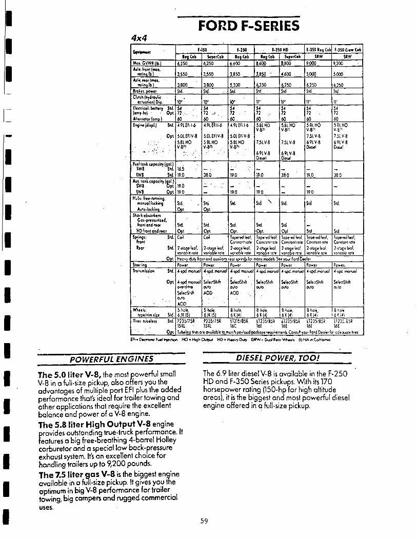
FORD F-SERIES 4 x 4
E^wtpMtfrt
Mo i GVWRJlb.)
Aile, front (mot. rttinq lb.)
Aile, rear (mai. relinq lb.)
I ro le i , power
Dutch (hydraulic actuation) Dio.
Electrical: battery Sid.
(omp-hr) • Opt.
Alternator (amp.)
Engine (diipl.) Sid.
O p t
Full tonic capacity (gal.)
SWB Std.
IWB Std.
A n . Ionic copocity (gal.)
SWB O p t
IWB O p t
Hubs: free-running,
monual locking
Auto-lockinq
Shock obsorberi
Gos.presturized,
front and nor
HD front ond rear
Springs: Std.
Front
( f o r Std.
Opt
Steerinq
Transmfiiion Std.
O p t
WK.1I1:
typo/rim site Std.
Tires: rubelesi Std.
O p t
f-150
l e g Cob
6,250
3.550
3,800
Std.
10" '
54 . 72 .
40
4.91 EH W
5.0LEFIV-8
5.81 HO
V-8") .
163 19.0
19.0 19.0
Std. ' .
Opt.
Std.
Opt
Coil
2-stoge leof, vorioble role
SuperCob
6,250
3 3 5 0
3,800
Std.
io-54
72 .-> .
60
4.9LEFIJ-6
5.01EFIV-8
5 81 HO V-8"i . .
38.0
_ • . • . ; •
Std.
Opt.
Std.
Opt.
Coil
2-stoge leof,
variable role
f-iso l e g Cob
6.600
3,850
5,300
Std.
10" 54 72 .
6 0 .
4.91EFII-6
501EFIV-8
5.81 HO V.8" ' .
190
19.0
Sid.
Std
Opt.
Topered leof,
Consicntrote
2-stoqe leof,
vcrioo'e rcrle
M $ 0 HD
Reg Cab
8,600
3,850 •
6,250
Std
11-
54 72
60
5.81 HO V-B"'
7.517-8
6 91 V-8 Diesel
19.0
19.0
Std N
Std
Opt
lope'tdleol,
Conslcnlrole
2-sloge leof,
voriob'e rc'e
Stipe rCob
8,800
4,600
6,750
Std
11-54
72
60
5.81 HO V . 6 «
7.51 V-8
691V-8 Diesel
380
-
Std.
Std.
Oof.
loperedleol,
Constant role
2-stoge leol.
voncble W e
f-350 Reg Cob
SOW
9,000
5,000
6,250
Std
11-54
72
60
5.81 HO V-B"!
7iLV-8
691V-8 Diesel
19.0
19.0
Sid
Std.
lopered leof, Constonl role
2-slocje leof. vonooie rote
F-350 Crew Cob
SRW
9,200
5.000
6,250
Std
11-54
72
60
5 81 HO
V-B'1'
7.5. V-8
69LV-8
Diesel
380
-
Srd.
Std.
lopered leal.
Constant rote
2-s'ogeleol,
vonooie ro'e
Heovy-duty front ond ouxiliory reor spr incji for mony models See your Ford Dealer.
Power
4-spd. manuol
4-spd manuol overdrive
SeleciShrft auto
AOD
5-rcle. 6JKI5)
Power
4-spd. monual
SeleclSbKt
outo
AOD
5-hole, 6JK15)
Power
4-spd. monual
SelectShifl .
outo
AOD
8-hole.
6K.J41
Power
4-spd manuol
SelectSMt outo
8-hole,
Power
4-spd. manual
SeleciShrft
outo
8-hole. 6KI4)
Power
4-spd. manuol
SeIe:tShrfl outo
8-hole,
Power.
4-spd monuol
Se'eciShm OV\D
B-r-.ol*.
P235/75R P235/75R U215/85R U235/85R 11235/851! U235/85R U23 ; .85R 15XL 15X1 16C 16E 16E I6E 16E
Tubeiess tires ore ovoJoble to motcfi oovlood pockoae reau'rements Consult your Fo'd Oeoler lo- cdesuole tires
EFI . E W » w » c fuel kiferton H O - KUghOutput H D - H « o v y Duly DRW = Dual BeorVvWK p) NA «< C o M o r o
POWERFUL ENGINES DIESEL POWER, TOO!
The 5.0 liter V - 8 , the most powerful small The 6.9 liter diesel V-8 is available in the F-250 V-8 in a full-size pickup, also offers you the HD and F-350 Series pickups. With its 170 advantages of multiple port EFI plus the added horsepower rating (150-hp for high altitude performance that's ideal for trailer towing and areas), it is the biggest ana most powerful diesel other applications that require the excellent engine offered in a full-size pickup. balance and power of a V-8 engine.
The 5.8 liter High Output V-8 engine provides outstanding true-truck performance. It features a big free-breathing 4-barrel Holley carburetor and a special low back-pressure exhaust system. It's an excellent choice for handling trailers up to 9,200 pounds.
The 7.5 liter gas V - 8 is the biggest engine available in o full-size pickup. It gives you the optimum in big V-8 performance for trailer towing, big campers and rugged commercial uses.
59


APPENDIX C
Down-the-hole Drills
- 61 -

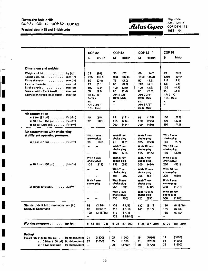
Down-the-hole drills COP 32 • COP 42 • COP 52 • COP 62 Principal data in SI and British units
JltlasCopcc Reg. code AMLTAB2 COPDTH-115 1986-04
Dimensions and weights
Weight excl. bit kg (lb)
External diameter mm (in)
Spanner width (back head) . . . . mm (in) Connection thread (back head) . mm (in)
Air consumption
at 10.5 bar (150 psi) . . . . . l/i (cfm) at 18 bar (260 pti) l/s (cfm)
Air consumption with choke plug at different operating pressures:
at 10.5 bar (150 psi) l/s (cfm)
Standard drill bit dimensions mm (in) Sandvik Coromant
Working pressures bar (psi)
Ratings impact rate at 6 bar (87 pti) . . . Hz (blows/min)
at 10.5 bar (150 psi) Hz (blows/min) at 18 bar (260 psi) Hz (blows/min)
COP 32
SI British
23 (51) 925 (36.4) 60 (2.4) 77 (3.1) 100 (3.9) 50 (2.0) Rd50-6 Female alt. API 2 3/8" REG. Male
40 (85) 77 (163) -
With 4 mm choke plug 50 (106) — —
-
With 4 mm choke plug 103 (218)
_ —
"
With 4 mm choke plug - -
_ _
-
85 (3 3/8) 90 (3 9/16) 100 (3 15/16) -
6-12 (87-174)
21 (1300) 27 (1650) —
COP 42
SI British
35 (77) 960 (37.8) 76 (3.0) 96 (3.8) 100 (3.9) 65 (2.6) API 2 3/8" REG. Male -—
62 (131) 115 (244) 200 (424)
With 5 mm choke plug 71 (151)
With 7 mm choke plug 102 (216)
With 5 mm choke plug 132 (280)
With 7 mm choke plug 185 (392)
With 5 mm choke plug 250 (530)
With 7 mm choke plug 330 (700)
105 (4 1/8) 110 (4 5/16) 115 (4 1/2) 125 (4 15/16)
6-25 (87-3601
21 (1300) 27 (1650) 35 (2100)
COP 52
SI British
66 (145) 1160 (45.3) 92 (3.6) 118 (4.6) 100 (3.9) 65 (2.6) API 2 3/8" REG. Male alt. API 3 1/2" REG. Male
65 (138) 130 (275) 220 (466)
With 7 mm choke plug 105 (223)
With 10 mm choke plug 125 (265)
With 7 mm choke plug. 200 (424)
With 10 mm choke plug 255 (541)
With 7 mm choke plug 350 (742)
With 10 mm choke plug 420 (890)
130 (5 1/8) 140 (5 1/2) --
6-25 (87-360)
18 (1080) 21 (1290) 28 (1700)
COP 62
SI British
93 (205) 1280 (50.4) 112 (4.4) 138 (5.4) 105 (4.1) 95 (3.7) API 3 1/2" REG. Male -—
100 1212) 200 (424) 350 (742)
With 7 mm choke plug 140 (297)
With 10 mm choke plug 160 (339)
With 7 mm choke plug 260 (551)
With 10 mm choke plug 325 (689)
With 7 mm choke plug 480 (1018)
With 10 mm choke plug 550 (1166)
150 (5 15/16) 155 (6 1/8) 165 (61/21 -
6-25 (87-360)
17 (1000) 21 (1300) 26 (1600)
63
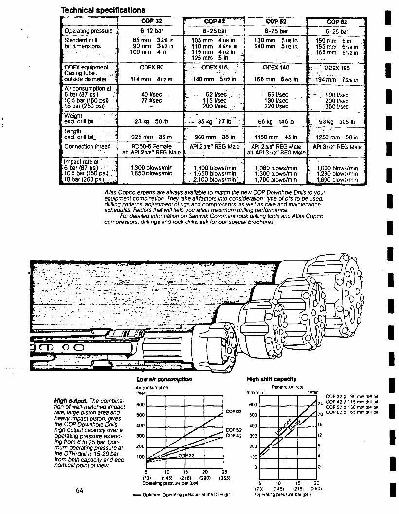
Technical specifications
•
Operating pressure ,
Standard drill bit dimensions
i . - - * -
COP 32
6-12 bar
85 mm 3 3/8 in 90 mm 31/2 in
100 mm 4 in
ODEX equipment ODEX90 Casing tube •;• :.,\ outside diameter 114 mm 4i/2 in
Air consumption at 6 bar (87 psi) ;; 10.5 bar (150 psi) \<
.18 bar (260 psi) _.
Weight excl. drill bit v •-\
Length -excl. drill bit. "
Connection thread
Impact rate at '•'•< 6 bar (87 psi) .•
, 10.5 bar (150 psi) .' t18 bar (260 psi) ^
40 l/sec 771/sec
23 kg 501b
925 mm 36 in
RD50-6 Female alt API 23/8" REG Male
r cop*f^"i 6-25 bar
105 mm 41/8 in ; 110 mm 45/16 in ; 115 mm 4i/2in ^
125 mm 5 in "
' •;;• ODEX 115.
; 140 mm 5i/2in :
t'•. '•-••' 6 2 1 / s e c •••.' •-. -.'•• 1151/sec , 2001/sec - ':, , . . . . . . . . • • • ' " _ •
• : • - 3 5 k o " . 7 7 t o - V j
: 960 mm 38 in
API 23/8" REG Male
>. - . • • . ' . . '
' - ••
1,300 blows/min 1,300 blows/min 1,650 blows/min - 1,650 blows/min
., 2.100blows/min.' „
COP 52 ' COP 62 !
6-25 bar 6-25 bar
130 mm 5i/ein ( 150 mm 6 in •; 140 mm 5i/2 in , 155 mm 61/e in •
165 mm 61/2 in •
ODEX 140 ; ' ODEX 165
168 mm 65/8 in ; 194 mm 75/8 in
65 l/sec 130 l/sec 220 l/sec
:.--'.. 1001/sec 2001/sec 350 l/sec
• • ' • ' .
66 kg 1451b i. 93 kg 2051b :
1150 mm 45 in ' 1280 mm 50 in
API 23/e" REG Male alt API 31/2" REG Male
1,080 blows/min 1,300 blows/min 1.700 blows/min
API 31/2" REG Male
1,000 blows/min - 1.290 blows/min '. ^ 1,600 blows/min
Atlas Copco experts are always available to match the new COP Downhole Drills to your equipment combination. They take all factors into consideration: type ol bits to be used, drilling patterns, adjustment of rigs and compressors, as we// as care and maintenance schedules. Factors that will help you attain maximum drilling performance
For detailed information on Sandvik Coromant rock drilling tools and Atlas Copco compressors, drill rigs and rock drills, ask for our special brochures.
High output The combination of well-matched impact rate, large piston area and heavy impact piston, gives the COP Downhole Drills high output capacity over a operating pressure extending from 6 to 25 bar. Optimum operating pressure at the DTH-drill is 15-20 bar from both capacity and economical point of view.
64
Lour afr consumption Air consumption l/sec
600
500
400
300
200
100
5 10 15 (73) (145) (218)
High shift capacity Penetration rate
mm/mm
*
.-<• **fc
» y »32
^
y ̂
%-""
COP 62
COP 52 COP 42
20 (290)
25 (363)
finn
•>nn
4 on
inn
?nn
100
n
\
/ y
f
A /
fy s
/ S k
COP 32 9 90 mm drill bit 24 COP 42 9 115 mm drill Dit
COP 52 a 130 mm drill bit 2 0 COP 62 9 165 mm drill bit
16
12
Operating pressure bar (psi)
— Optimum Operating pressure at the DTH-dnll
5 10 15 20 (73) (145) (218) (290) Operating pressure bar (psi)
APPENDIX D
Mud Tank
- 65 -

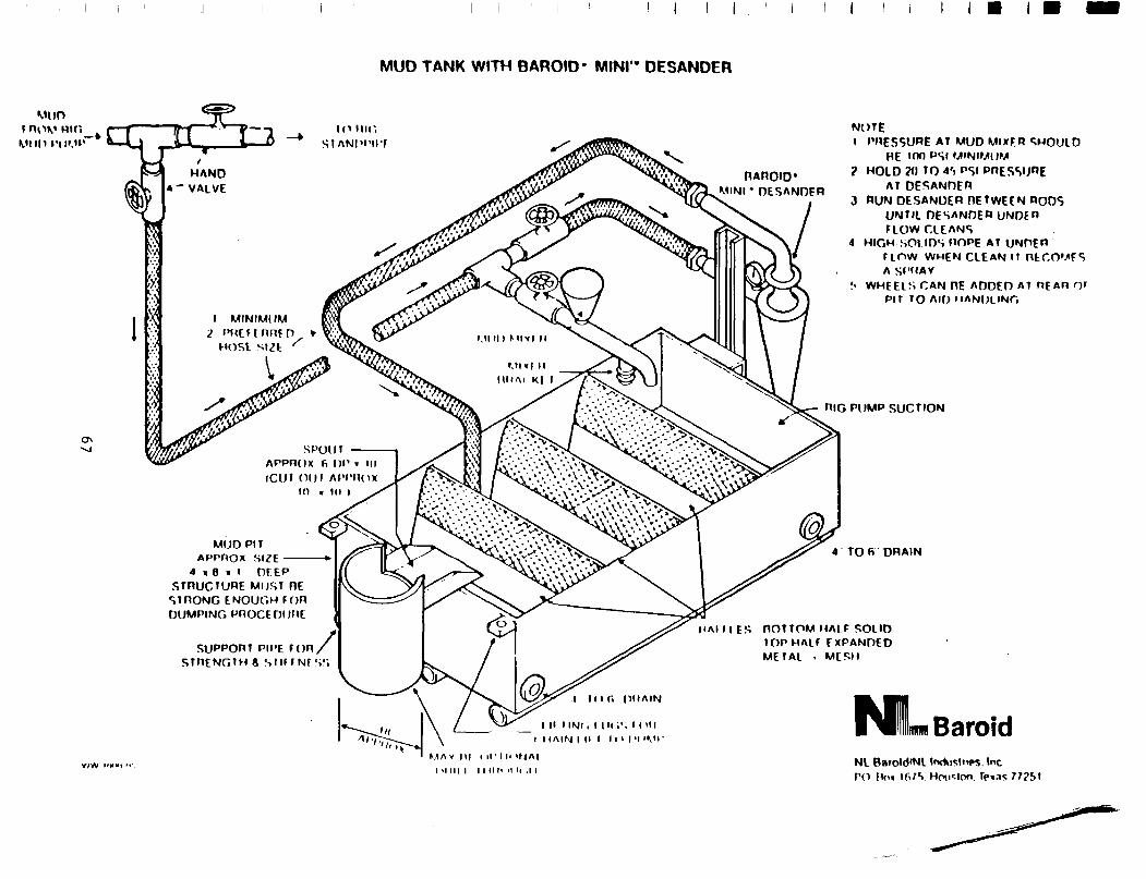
MUD TANK WITH BAROID" MINI'• DESANDER
I 1 I
MUD f n o v R" t
v i in I ' I I ' ." ' —k
ON
1(1 UK', s t ANpi' i i-r
I • : • /
I MINIMUM i P M C f f n n f n
HOSt SIZfc
S P O U I A P P R O X 6 n i
iCUt (MM APPRox in > in i
MUD PIT APPrtox SI£E
4 « 8 « l OFEP STRUCTURE MUST RE
STRONG E N O U G H TOR DUMPING PROCEDURE
SUPPORT Pll STRENGTH « S U I T Nt SS
PE T O R /
nAnoio* M I N I " DESANDER
NOTE I PRESSURE AT MUD MlxER SHOULD
HE inn »»SI MINIMUM ? HOLD W TO 4') PSI PRESSURE
AT DESANDER 3 RUN DESANDER RETWEEN RODS
UNTIL DESANDER UNDER FLOW CLEANS
4 HIGH SOt IDS ROPE AT UNDER now WHEN CLEAN IT nt COMES A SPRAY
:< WHEELS CAN HE ADDED AT REAR 0»" PIT TO AID HANDLING
RIG PUMP S U C T I O N
4 T O f i DRAIN
1 A I I I E S ROT TOM HALF SOLID TOP HALT EXPANDED METAL . MESH
M I INi i I l i t ' . ' . I I 'H I IAIN I II I l i > I'l ' V I '
Ifflffll Baroid M A V |lf I ll I I. I fJAI
I H i l l I I I I I I ' H It ,1 I NL Barold'Nl Industries Inc PO Ho» lfi»"S. Hcnislon. Te«as77?5t
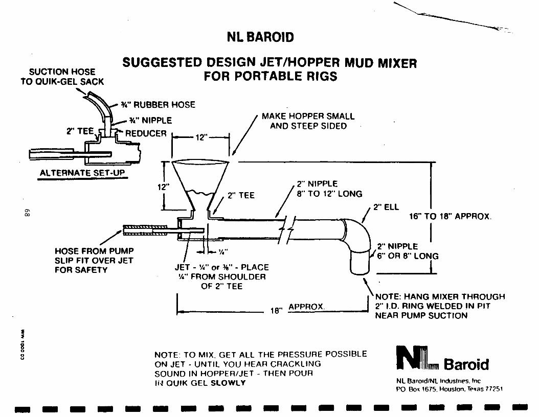
NL BAROID
SUCTION HOSE TO OUIK-GEL SACK
SUGGESTED DESIGN JET/HOPPER MUD MIXER FOR PORTABLE RIGS
CXI
f
8 o o
%" RUBBER HOSE
%" NIPPLE
REDUCER
ALTERNATE SET-UP
HOSE FROM PUMP SLIP FIT OVER JET FOR SAFETY
MAKE HOPPER SMALL AND STEEP SIDED
2" NIPPLE 8" TO 12" LONG
JET - V»" or %" - PLACE %" FROM SHOULDER
OF 2" TEE
18
, 2" ELL / 16" TO 18" APPROX
.. APPROX
2" NIPPLE 6" OR 8" LONG
L NOTE: HANG MIXER THROUGH 2" ID . RING WELDED IN PIT NEAR PUMP SUCTION
NOTE: TO MIX. GET ALL THE PRESSURE POSSIBLE ON JET - UNTIL YOU HEAR CRACKLING SOUND IN HOPPER/JET - THEN POUR IN OUIK GEL SLOWLY
l^BIILim Baro id NL Baroid/NL Industries. Inc PO Box 1675. Houston. Texas 77251
APPENDIX E
Hydrofracturing Pump
- 69 -

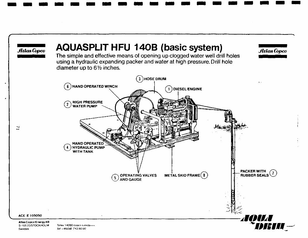
JhlasCopco AQUASPLITHFU 140B (basic system) The simple and effective means of opening up clogged water well drill holes using a hydraulic expanding packer and water at high pressure. Drill hole diameter up to 6V2 inches.
JUlasCopco
ACE E 105050
)HOSE DRUM
© HAND OPERATED WINCH 1 ) DIESEL ENGINE
© HIGH PRESSURE WATER PUMP -
©HAND OPERATED HYDRAULIC PUMP WITH TANK
© OPERATING VALVES AND GAUGE
PACKER WITH / T \ RUBBER SEALS \U
*v-̂ Atlas Copco Energy AB S-105 23 STOCKHOLM Sweden
Tele» I4090cooco se»da» Tel .46(018 743 80 00
uwmM * in: 111
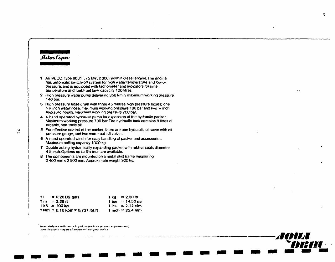
JUiasCopco
1 An IVECO, type 80611,75 kW, 2 300 rev/min diesel engine.The engine has automatic switch-off system for high water temperature and low oil pressure, and is equipped with tachometer and indicators for time, temperature and fuel. Fuel tank capacity 120 litres.
2 High pressure water pump delivering 350 l/min, maximum working pressure 140 bar.
3 High pressure hose drum with three 45 metres high pressure hoses; one 1V* inch water hose, maximum working pressure 180 bar and two V* inch hydraulic hoses, maximum working pressure 700 bar.
4 A hand operated hydraulic pump for expansion of the hydraulic packer. Maximum working pressure 700 bar.The hydraulic tank contains 8 litres of organic, non-toxic oil.
5 For effective control of the packer, there are one hydraulic oil valve with oil pressure gauge, and two water cut-off valves.
6 A hand operated winch for easy handling of packer and accessories. Maximum pulling capacity 1000 kg.
7 Double acting hydraulically expanding packer with rubber seals diameter 4Vi inch. Options up to 6Vi inch are available.
8 The components are mounted on a metal skid frame measuring 2 400 mmx 2 500 mm. Approximate weight 900 kg.
1 I = 0.26 US gals 1 kg = 2.20 lb 1 m = 3.28 ft 1 bar = 14.50 psi 1 kN = 1 0 0 k p 1 l/s = 2 . 1 2 c f m 1 Nm = 0.10 kpm= 0.737 Ibf.ft 1 inch = 25.4 mm
In accordance with our policy ol progressive product improvement, specifications may be changed without prior notice
jlfMJbl
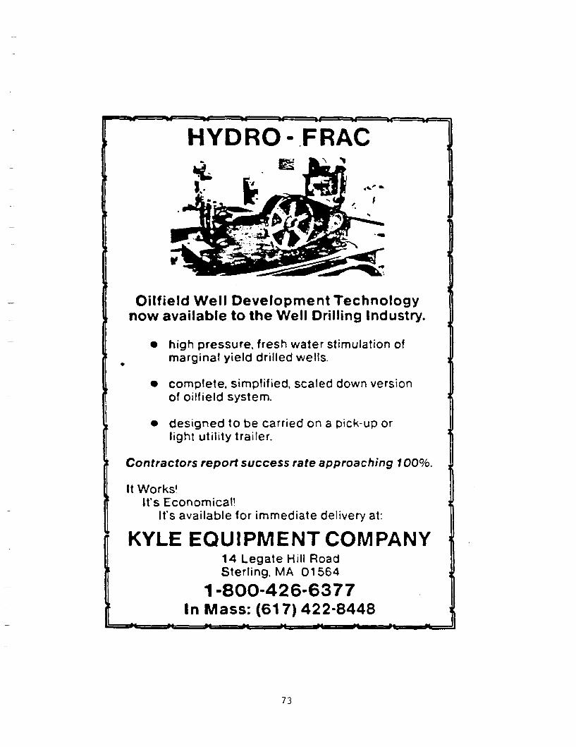
M ' W =%«=
HYDRO-FRAC
Oilfield Well Development Technology now available to the Well Drilling Industry.
• high pressure, fresh water stimulation of marginal yield drilled wells.
• complete, simplified, scaled down version of oilfield system.
• designed to be carried on a pick-up or light utility trailer.
Contractors report success rate approaching 100%.
It Works' It's Economical!
It's available for immediate delivery at:
KYLE EQUIPMENT COMPANY \ 14 Legate Hill Road Sterling, MA 01564
1-800-426-6377 In Mass: (617) 422-8448
*% *fe
73

APPENDIX F
Deep Rock Literature
- 75 -

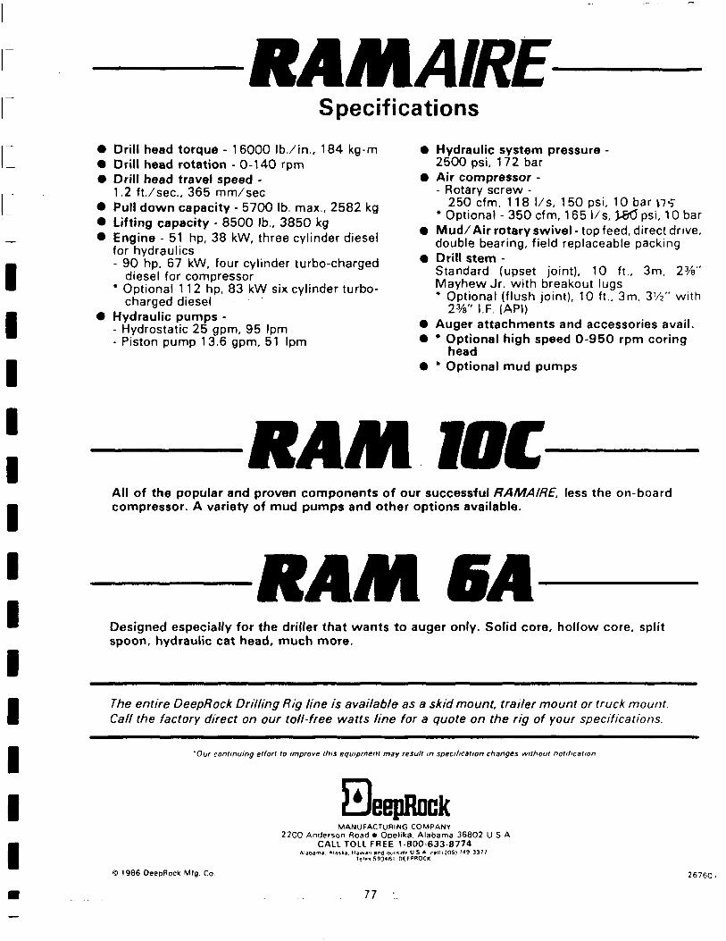
RAMAIRE Specifications
Drill head torque - 16000 Ib. / in. , 184 kg-m Drill head rotation - 0-140 rpm Drill head travel speed -1.2 f t . / sec , 365 mm/sec Pull down capacity - 5700 lb. max., 2582 kg Lifting capacity - 8500 lb., 3850 kg Engine - 51 hp, 38 kW, three cylinder diesel for hydraulics - 90 hp, 67 kW, four cylinder turbo-charged
diesel for compressor * Optional 112 hp, 83 kW six cylinder turbo-
charged diesel Hydraulic pumps -- Hydrostatic 25 gpm, 95 Ipm - Piston pump 13.6 gpm, 51 Ipm
Hydraulic system pressure -2500 psi, 172 bar Air compressor -- Rotary screw -
250 cfm, 118 l /s, 1 50 psi, 10 bar p- j * Optional - 350 cfm, 165 l /s, )&5 psi, 10 bar Mud/Air rotary swivel - top feed, direct drive, double bearing, field replaceable packing Drill stem -Standard (upset joint), 10 ft., 3m, 23/a" Mayhew Jr. with breakout lugs * Optional (flush joint), 10 ft., 3m, V/*" with
2%" I.F. (API) Auger attachments and accessories avail. * Optional high speed 0 -950 rpm coring
head * Optional mud pumps
RAM WC All of the popular and proven components of our successful RAMAIRE, less the o n b o a r d compressor. A variety of mud pumps and other options available.
RAMBA Designed especially for the driller that wants to auger only. Solid core, hollow core, split spoon, hydraulic cat head, much more.
The entire DeepRock Drilling Rig line is available as a skid mount, trailer mount or truck mount. Calf the factory direct on our toll-free watts line for a quote on the rig of your specifications.
'Our continuing effort to improve this equipment may result in specification changes without notification
HeepRock MANUFACTURING COMPANY
2200 Anderson Road • Opelika. Alabama 36802 U S A CALL TOLL FREE 1-800 633-8774
Araba-m Ai*,ka na*»*» »nd ouH'fl, U S A rail |J05) ?49 3377 te'»> 593461 DEfKOClC
1986 OeepRock Mlg Co 26760".
11
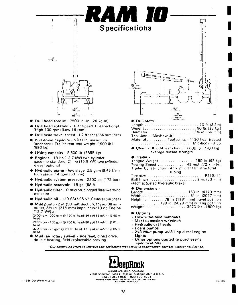
Jl RAM W Specifications
• Drill head torque - 7500 lb -in. (26 kg-m)
• Drill head rotation - Dual Speed, Bi-Directional. (High 130 rpm) (Low 16 rpm)
• Drill head travel speed - 1 2 f t /sec (366 mm/sec)
• Pull down capacity - 5700 lb maximum (anchored) Trailer rear end weight (1500 lb.) (680 kg)
• Lifting capacity - 8.500 lb (3855 kg)
• Engines - 18 hp (1 2.7 kW) two cylinder gasoline standard. 21 hp (15,6 kW) two cylinder diesel optional
• Hydraulic pump - low stage, 2.5 gpm (9,46 l /m); high stage, 14 gpm (53 l /m)
• Hydraulic system pressure - 2500 psi (172 bar)
• Hydraulic reservoir - 15 gal (68 I)
• Hydraulic fi lter-10 micron, clogged filter warning indicator
• Hydraulic oil - 150 SSU-95 VI (General purpose)
• Mud pump - 2 in. (50 mm) suction, 1 '/j in. (38 mm) outlet, 8V2 in (216 mm) impeller w / 1 8 hp Engine (12.7 kW)at: 2400 rpm • 200 gpm @ 1 30 ft head (56 psi) 55 m V h r @ 40 m head
2800 rpm - 1 50 gpm @ 200 ft head (86 ps i )41 m ' / h r @ 61 m head
3200 rpm • 75 gpm @ 280 ft head (121 psi) 20 m ' / h r @ 85 m head
• Mud/a i r rotary swivel - side feed, direct drive, double bearing, field replaceable packing.
Ttj|v»l Po»'t'On
• Drill stem -Length 10 ft. (3 3m) Weight 50 lb. (23 kg.) Diameter 2Va in (60 mm) Tool Joint - Mayhew Jr. Material Tool joints - 41 30 heat treated
Mid-body - J-55
• Chain - BL 634 leaf chain, 1 7.000 lb (7700 kg) average tensile strength
• Trailer -Tongue Weight 1 50 lb. (68 kg) Towing Speed 45 mph (72 km/hr) Trailer Construction - 4 " x 2" x 3 / 1 6 " structural
tubing Tire size P215/14 Ball hitch 2 in (50 mm) Hitch actuated hydraulic brake
• Dimensions -Length 163 in (4140 mm) Width 81 in. (2057 mm) Height 78 in. (1 981 mm) travel position
198 in. (5029 mm) drill ing position Weight 3970 lbs (1800 kg)
• Options - Down-the-hole hammers - Mast extension w /w inch - Hydraulic cat heads - Foam pumps - 2x3 Mud pump w / 3 1 hp diesel engine - Lights - Other options quoted to purchaser's
specifications Our continuing effort to improve this equipment may result in specification changes without notification
a eepRock
1986 DeepRock Mlg Co
MANUFACTURING COMPANY 2200 Anderson Road • Opelika. Alabama 36802 U S A
CALL TOLL FREE 1 800 633 8774 Alabama Alaska H i w m and O U U K I * U S A call 12051 749 33 '7
Ial-< 59346' OEEPHOCK 354607
78
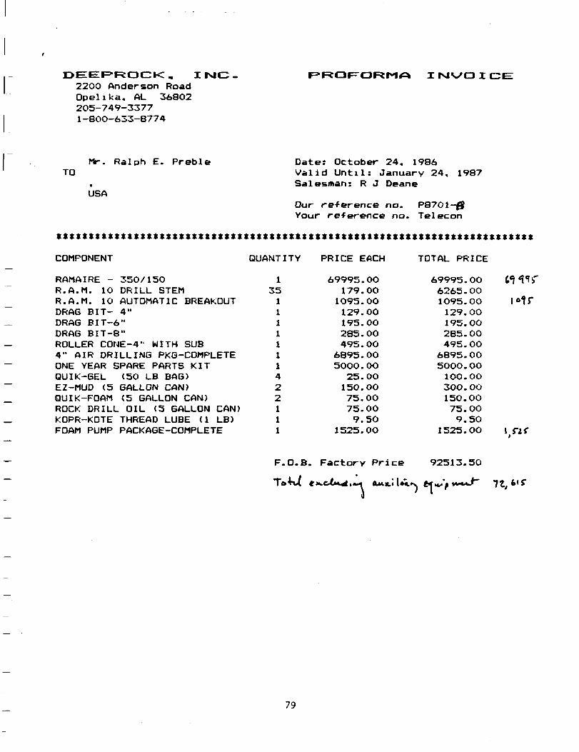
D E E P R O C K , I txJC 2200 Ande rson Road O p e l i k a , AL 36802 2 0 5 - 7 4 9 - 3 3 7 7 1 - 8 0 0 - 6 3 3 - 8 7 7 4
F ^ R O F ' O R M * * I N V O I C I
TO Mr. R a l p h E. P r e b l e
USA
Date: October 24, 1986 Valid Until: January 24, 1987 Salesman: R J Deane
Our reference no. P87O1-0 Vour reference no. Telecon
xxxxxxxxxxxxxxxxxxxxxxxxxxxxxxxxxxxxxtxxxxxxxxxxxxxxxxxxxxxxxxxxxxxxxxxxxx
COMPONENT
RAMAIRE - 350/150 R.A.M. 10 DRILL STEM R.A.M. 10 AUTOMATIC BREAKOUT DRAG BIT- 4" DRAG BIT-6" DRAG BIT-8" ROLLER CONE-4" WITH SUB 4" AIR DRILLING PKG-COMPLETE ONE YEAR SPARE PARTS KIT QUIK-GEL (50 LB BAG) E2-MUD (5 GALLON CAN) OUIK-FOAM (5 GALLON CAN) ROCK DRILL OIL (5 GALLON CAN) KOPR-KOTE THREAD LUBE (1 LB) FOAM PUMP PACKAGE-COMPLETE
QUANTITY
1 35 1 1 1 1 1 1 1 4 2 2 1 1 1
PRICE EACH
69995.OO 179.OO
1095.OO 129.00 195.00 285.00 495.OO
6895.00 5000.OO
25. OO 150.00 75.00 75. OO 9.50
1525.OO
TOTAL PRICE
F . O . B . F a c t o r y P r i c e
69995.00 6265.00 1095.00 129.00 195.00 285.00 495.00
6895.00 5000.00 100.00 300.OO 150.00 75.00 9.50
1525.00
92513.50
«11f
i»lr
i,n*
TaVU e».c4*t4t** 4M.K.il«i»v t*>Jf *~J~ 7£,*<?
79
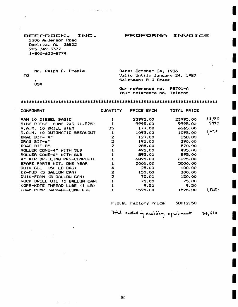
D E E P R O C K , I N C . 2200 A n d e r s o n Road O p e l i k a , AL 36802 2 0 5 - 7 4 9 - 3 3 7 7 1 - 8 0 0 - 6 3 3 - 8 7 7 4
P R O F O R M A I N V O I C E
TO Mr. Ralph E. Preble
USA
Date: October 24, 1986 Valid Until: January 24, Salesman: R J Deane
1987
Our reference no. P8701-A Your reference no. Telecon
**t**s*««tt«sttt*«t*stt**t*tk*tt*ttt*s*x**ttkttst*tt*sx*stt«s*«***tt«*>*t«
COMPONENT
RAM 10 DIESEL BASIC 51HP DIESEL PUMP 2X3 (1.875) R.A.M. 10 DRILL STEM R.A.M. 10 AUTOMATIC BREAKOUT DRAG BIT- 4" DRAG BIT-6" DRAG BIT-8" ROLLER CONE-4" WITH SUB ROLLER CONE-6" WITH SUB 4" AIR DRILLING PKG-COMPLETE SPARE PARTS KIT, ONE YEAR QUIK-GEL (50 LB BAG) EZ-MUD (5 GALLON CAN) QUIK-FDAM (5 GALLON CAN) ROCK DRILL OIL (5 GALLON CAN) KOPR-KOTE THREAD LUBE (1 LB) FOAM PUMP PACKAGE-COMPLETE
QUANTITY
1 1
35 1 2 2 2 1 1 1 1 4 2 2 1 1 1
PRICE EACH
23995.OO 9995.00 179.OO
1095.00 129.OO 195.00 285.OO 495.00 895.OO
6895.00 5000.OO
25.00 150.OO 75.00 75. OO 9.50
1525.OO
TOTAL PRICE
23995.00 9995.00 6265.OO 1095.00 258.OO 390.00 570.OO 495.00 895.00
6895.00 5OO0.00 100.00 300.00 150.00 75.00 9.50
1525.00 I . W
F.O.B. Factory Price 58012.50
" W U tKcXAa.^. AHjfc",IIVM, «<<A.'****w*r ^fc14l«
80
APPENDIX G
Canterra Literature
- 81 -

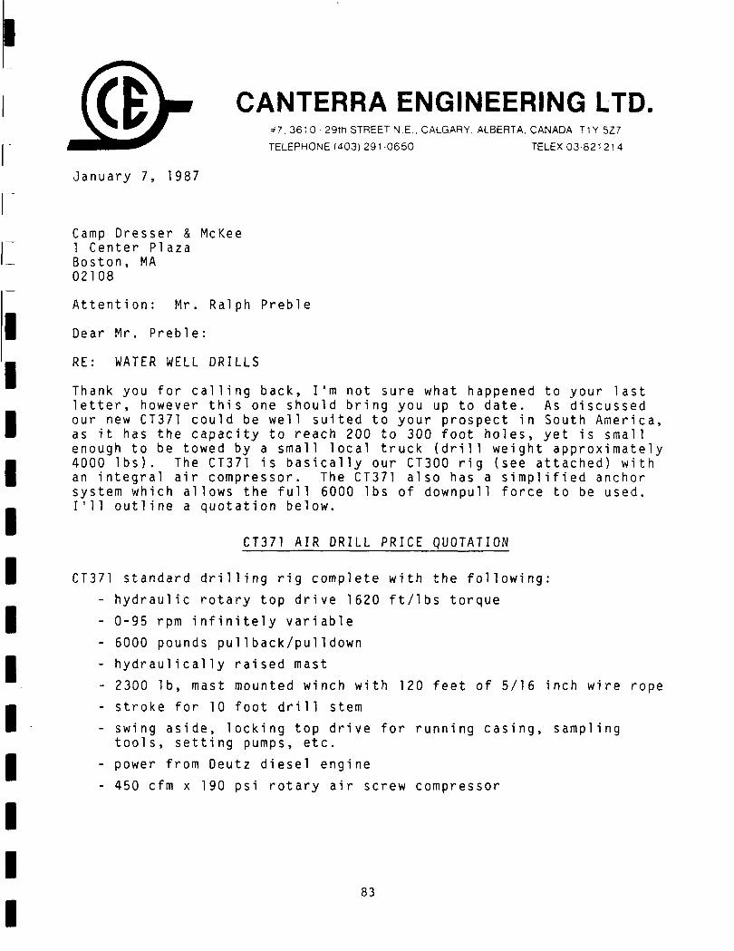
CANTERRA ENGINEERING LTD. * 7 . 3 6 1 0 - 2 9 t h STREET N.E.. CALGARY. ALBERTA. CANADA T1Y 5Z7
TELEPHONE (403) 291 -0650 TELEX 03-821214
January 7, 1987
Camp Dresser & McKee 1 Center Plaza Boston, MA 02108
Attention: Mr. Ralph Preble
Dear Mr. Preble:
RE WATER WELL DRILLS
Thank you for calling back, I'm not sure what happened to your last letter, however this one should bring you up to date. As discussed our new CT371 could be well suited to your prospect in South America, as it has the capacity to reach 200 to 300 foot holes, yet is small enough to be towed by a small local truck (drill weight approximately 4000 lbs). The CT371 is basically our CT300 rig (see attached) with an integral air compressor. The CT371 also has a simplified anchor system which allows the full 6000 lbs of downpull force to be used. I'll outline a quotation below.
CT371 AIR DRILL PRICE QUOTATION
CT371 standard drilling rig complete with the following:
- hydraulic rotary top drive 1620 ft/lbs torque
- 0-95 rpm infinitely variable
- 6000 pounds pul1back/pul1 down
- hydraulically raised mast
- 2300 lb, mast mounted winch with 120 feet of 5/16 inch wire rope
- stroke for 10 foot drill stem
- swing aside, locking top drive for running casing, sampling tools, setting pumps, etc.
- power from Deutz diesel engine
- 450 cfm x 190 psi rotary air screw compressor
83
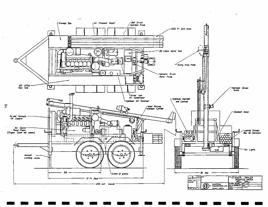
Air end HfOrauic • 03 Coolers
Air Cooled -Diesel Engine
(Engine Cottr not stoxn)
Bell Driven MyOrouhc Pimp
Manual Lmetlmg Jocks
grovity
10 Ft Dex*-
-205 Inctt Overall-
-Hydraulic Driven Winch
-OomfUl Motor
81 Inch
*'ne Storage Bow tor Hammers
-Toil Lights
k
»MTT«.,»
_. J
»
/ £ * \ CAMTWM I f p >— t»OI»I««"IM ITO \ - -S b u m «t««i*
MCXWTED »KTER WELL r»ui
k > u J / M •—» ftfM^TT
—: _.
— ./*> _ . —
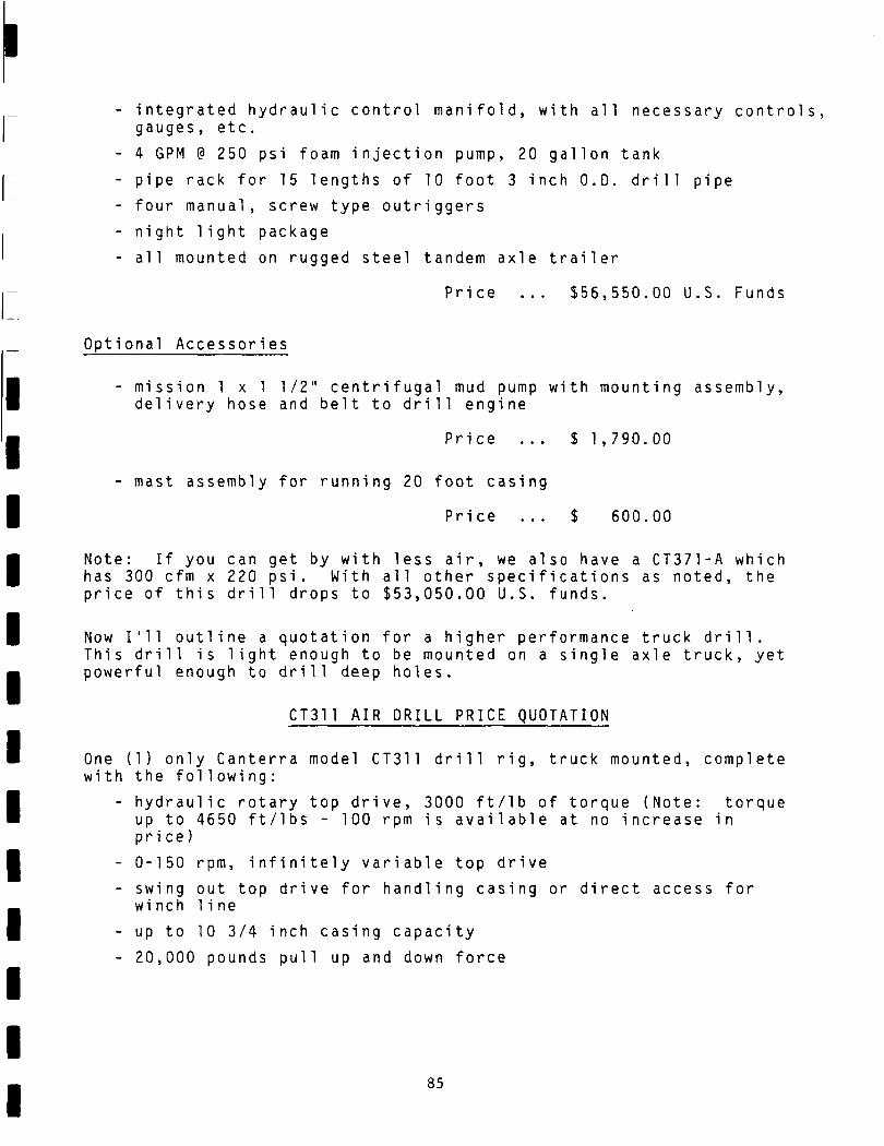
- integrated hydraulic control manifold, with all necessary controls, gauges, etc.
- 4 GPM @ 250 psi foam injection pump, 20 gallon tank
- pipe rack for 15 lengths of 10 foot 3 inch O.D. drill pipe
- four manual, screw type outriggers
- ni ght light package
- all mounted on rugged steel tandem axle trailer
Pri ce $56,550.00 U.S. Funds
Optional Aceessories
mission 1 x 1 1/2" centrifugal mud pump with mounting assembly, delivery hose and belt to drill engine
Pri ce $ 1,790.00
- mast assembly for running 20 foot casing
Price ... $ 600.00
Note: If you can get by with less air, we also have a CT371-A which has 300 cfm x 220 psi. With all other specifications as noted, the price of this drill drops to $53,050.00 U.S. funds.
Now I'll outline a quotation for a higher performance truck drill. This drill is light enough to be mounted on a single axle truck, yet powerful enough to drill deep holes.
CT311 AIR DRILL PRICE QUOTATION
One (1) only Canterra model CT311 drill rig, truck mounted, complete with the fol1owi ng :
- hydraulic rotary top drive, 3000 ft/lb of torque (Note: torque up to 4650 ft/lbs - 100 rpm is available at no increase in price)
- 0-150 rpm, infinitely variable top drive
- swing out top drive for handling casing or direct access for wi nch 1i ne
- up to 10 3/4 inch casing capacity
- 20,000 pounds pull up and down force
85
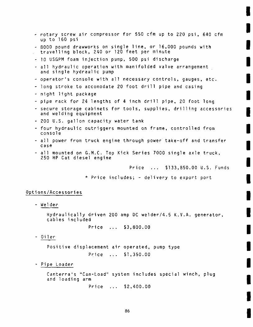
- rotary screw air compressor for 550 cfm up to 220 psi, 640 cfm up to 160 psi
- 8000 pound drawworks on single line, or 16,000 pounds with travelling block, 240 or 120 feet per minute
- 10 USGPM foam injection pump, 500 psi discharge
- all hydraulic operation with manifolded valve arrangement and single hydraulic pump
- operator's console with all necessary controls, gauges, etc.
- long stroke to accomodate 20 foot drill pipe and casing
- night light package
- pipe rack for 24 lengths of 4 inch drill pipe, 20 foot long
- secure storage cabinets for tools, supplies, drilling accessories and welding equipment
- 200 U.S. gallon capacity water tank
- four hydraulic outriggers mounted on frame, controlled from console
- all power from truck engine through power take-off and transfer case
- all mounted on G.M.C. Top Kick Series 7000 single axle truck, 250 HP Cat diesel engine
Price ... $133,850.00 U.S. Funds
* Price includes; - delivery to export port
Options/Accessories
- Weider
Hydraulically driven 200 amp DC welder/4.5 K.V.A. generator, cables included
Price ... $3,800.00
- Oiler
Positive displacement
Price
- Pipe Loader
Canterra's "Can-Load" and loading arm
Pri ce
86
air operated, pump type
.. $1,350.00
system includes special winch, plug
.. $2,400.00
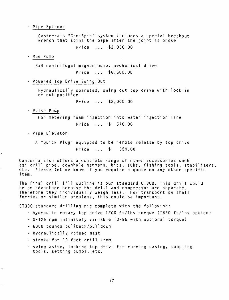
- Pipe Spinner
Canterra's "Can-Spin" system includes a special breakout wrench that spins the pipe after the joint is broke
Pri ce $2,000.00
Mud Pump
3x4 centrifugal magnum pump, mechanical drive
Price ... $6,600.00
- Powered Top Drive Swing Out
Hydraulical1y operated, swing out top drive with lock in or out position
Price ... $2,000.00
- Pulse Pump
For metering foam injection into water injection line
Price ... $ 570.00
- Pipe Elevator
A "Quick Plug" equipped to be remote release by top drive
Price ... $ 350.00
Canterra also offers a complete range of other accessories such as; drill pipe, downhole hammers, bits, subs, fishing tools, stabilizers, etc. Please let me know if you require a quote on any other specific item.
The final drill I'll outline is our standard CT300. This drill could be an advantage because the drill and compressor are separate. Therefore they individually weigh less. For transport on small ferries or similar problems, this could be important.
CT300 standard drilling rig complete with the following:
- hydraulic rotary top drive 1200 ft/lbs torque (1620 ft/lbs option)
- 0-125 rpm infinitely variable (0-95 with optional torque)
- 6000 pounds pul1back/pul1 down
- hydraulically raised mast
- stroke for 10 foot drill stem
- swing aside, locking top drive for running casing, sampling tools, setting pumps, etc.
87
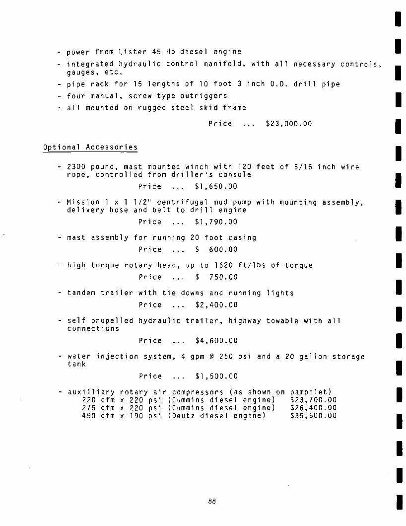
- power from Lister 45 Hp diesel engine
- integrated hydraulic control manifold, with all necessary controls, gauges, etc.
- pipe rack for 15 lengths of 10 foot 3 inch O.D. drill pipe
- four manual, screw type outriggers
- all mounted on rugged steel skid frame
Price $23,000.00
Optional Accessories
2300 pound, mast mounted winch with 120 feet of 5/16 inch wire rope, controlled from driller's console
Pri ce $1,650.00
- Mission 1 x 1 1/2" centrifugal mud pump with mounting assembly, delivery hose and belt to drill engine
Price ... $1,790.00
- mast assembly for running 20 foot casing
Price ... $ 600.00
- high torque rotary head, up to 1620 ft/lbs of torque
Price ... $ 750.00
- tandem trailer with tie downs and running lights
Price ... $2,400.00
- self propelled hydraulic trailer, highway towable with all connecti ons
Pri ce $4,600.00
water injection system, 4 gpm @ 250 psi and a 20 gallon storage tank
Pri ce $1,500.00
auxilliary rotary air compressors (as shown on pamphlet) 220 cfm x 220 psi (Cummins diesel engine) $23,700.00 275 cfm x 220 psi (Cummins diesel engine) $26,400.00 450 cfm x 190 psi (Deutz diesel engine) $35,600.00
88
I hope the above answers some of the questions you had. It may also be of interest to you that Canterra has exported equipment into (18) overseas countries and we provide on-site set up and training anywhere in the world. Thanks again for your cal1, I hope we can put some equipment in South America for you.
Yours truly,
GINGERING LTD
(oward) Jackson •esident Sales
HGJ/co End osures (2) CT311, (2) CT311M, (2) CT300, (2) CT371, (1) Corporate
89
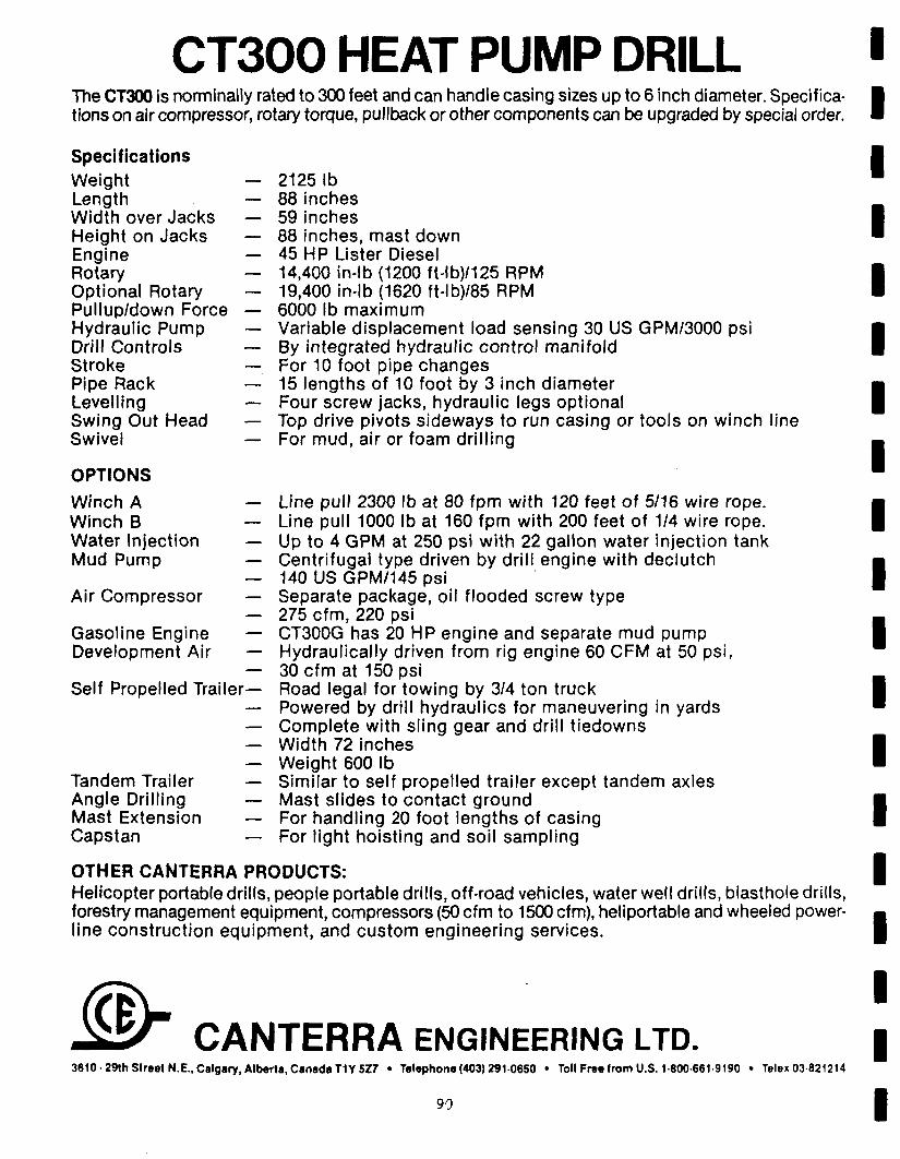
CT300 HEAT PUMP DRILL The CT300 is norminally rated to 300 feet and can handle casing sizes up to 6 inch diameter. Specifications on air compressor, rotary torque, pullback or other components can be upgraded by special order.
Specifications Weight — Length — Width over Jacks — Height on Jacks — Engine — Rotary — Optional Rotary — Pullup/down Force — Hydraulic Pump — Drill Controls — Stroke — Pipe Rack — Levelling — Swing Out Head — Swivel —
OPTIONS
Winch A — Winch B — Water Injection — Mud Pump —
Air Compressor —
Gasoline Engine — Development Air —
Self Propelled Trai ler-
Tandem Trailer Angle Drilling Mast Extension Capstan
2125 lb 88 inches 59 inches 88 inches, mast down 45 HP Lister Diesel 14,400 in-lb (1200 ft-lb)/125 RPM 19,400 in-lb (1620 ft-lb)/85 RPM 6000 lb maximum Variable displacement load sensing 30 US GPM/3000 psi By integrated hydraulic control manifold For 10 foot pipe changes 15 lengths of 10 foot by 3 inch diameter Four screw jacks, hydraulic legs optional Top drive pivots sideways to run casing or tools on winch line For mud, air or foam drilling
Line pull 2300 lb at 80 fpm with 120 feet of 5/16 wire rope. Line pull 1000 lb at 160 fpm with 200 feet of 1/4 wire rope. Up to 4 GPM at 250 psi with 22 gallon water injection tank Centrifugal type driven by drill engine with declutch 140 US GPM/145 psi Separate package, oil flooded screw type 275 cfm, 220 psi CT300G has 20 HP engine and separate mud pump Hydraulically driven from rig engine 60 CFM at 50 psi, 30 cfm at 150 psi Road legal for towing by 3/4 ton truck Powered by drill hydraulics for maneuvering in yards Complete with sling gear and drill tiedowns Width 72 inches Weight 600 lb Similar to self propelled trailer except tandem axles Mast slides to contact ground For handling 20 foot lengths of casing For light hoisting and soil sampling
OTHER CANTERRA PRODUCTS: Helicopter portable drills, people portable drills, off-road vehicles, water well drills, blasthole drills, forestry management equipment, compressors (50 cfm to 1500 cfm), heliportable and wheeled power-line construction equipment, and custom engineering services.
B- CANTERRA ENGINEERING LTD. 3610-29th Street N.E., Calgary, Alberta, Canada T1Y5Z7 • Telephone (403) 2910650 • Toll Free from U.S. 1800-661 9190 • Telex 03-821214
90

APPENDIX H
Simco Literature
- 91 -

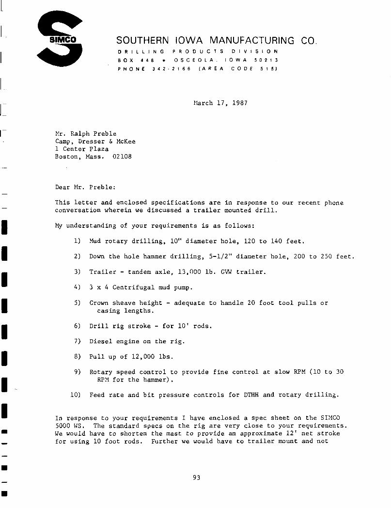
SIMCO SOUTHERN IOWA MANUFACTURING CO. D R I L L I N G P R O D U C T S D I V I S I O N
B O X 4 4 8 • O S C E O L A . I O W A 5 0 2 1 3
P H O N E 3 4 2 - 2 1 6 6 ( A R E A C O D E 5 1 5 )
March 17, 1987
Mr. Ralph Preble Camp, Dresser & McKee 1 Center Plaza Boston, Mass. 02108
Dear Mr. Preble:
This letter and enclosed specifications are in response to our recent phone conversation wherein we discussed a trailer mounted drill.
My understanding of your requirements is as follows:
1
2
3
4
5
6
7
8
9
10
Mud rotary drilling, 10" diameter hole, 120 to 140 feet.
Down the hole hammer drilling, 5-1/2" diameter hole, 200 to 250 feet,
Trailer - tandem axle, 13,000 lb. GVW trailer.
3 x 4 Centrifugal mud pump.
Crown sheave height - adequate to handle 20 foot tool pulls or casing lengths.
Drill rig stroke - for 10' rods.
Diesel engine on the rig.
Pull up of 12,000 lbs.
Rotary speed control to provide fine control at slow RPM (10 to 30 RPM for the hammer).
Feed rate and bit pressure controls for DTHH and rotary drilling.
In response to your requirements I have enclosed a spec sheet on the SIMCO 5000 WS. The standard specs on the rig are very close to your requirements, We would have to shorten the mast to provide an approximate 12' net stroke for using 10 foot rods. Further we would have to trailer mount and not
93
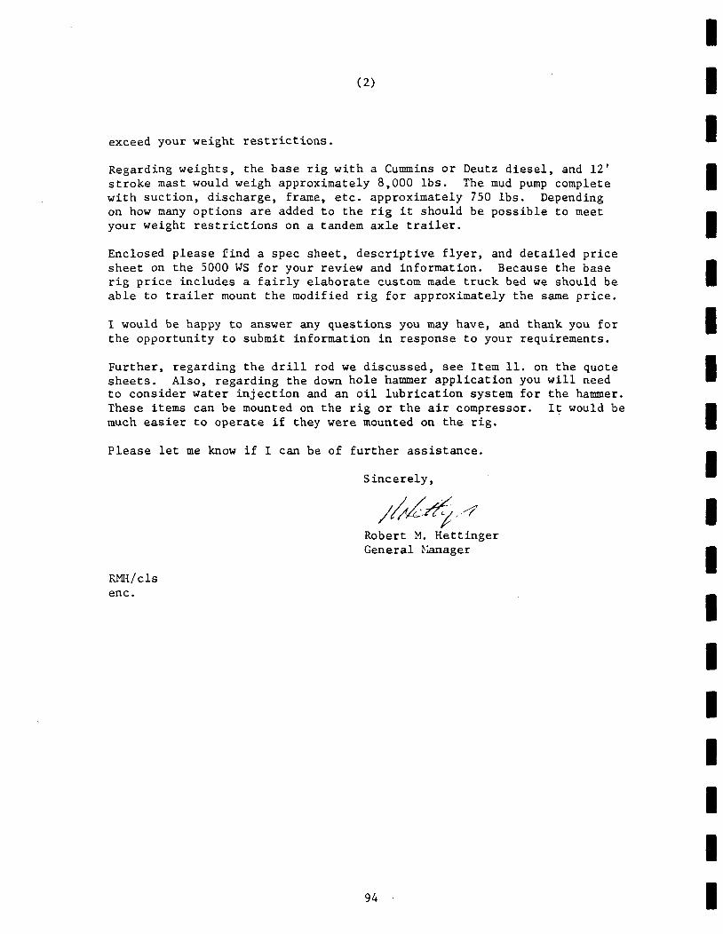
(2)
exceed your weight restrictions.
Regarding weights, the base rig with a Cummins or Deutz diesel, and 12' stroke mast would weigh approximately 8,000 lbs. The mud pump complete with suction, discharge, frame, etc. approximately 750 lbs. Depending on how many options are added to the rig it should be possible to meet your weight restrictions on a tandem axle trailer.
Enclosed please find a spec sheet, descriptive flyer, and detailed price sheet on the 5000 WS for your review and information. Because the base rig price includes a fairly elaborate custom made truck bed we should be able to trailer mount the modified rig for approximately the same price.
I would be happy to answer any questions you may have, and thank you for the opportunity to submit information in response to your requirements.
Further, regarding the drill rod we discussed, see Item 11. on the quote sheets. Also, regarding the down hole hammer application you will need to consider water injection and an oil lubrication system for the hammer. These items can be mounted on the rig or the air compressor. It would be much easier to operate if they were mounted on the rig.
Please let me know if I can be of further assistance.
Sincerely,
Robert M. Hettinger General Manager
RMH/cls enc.
94
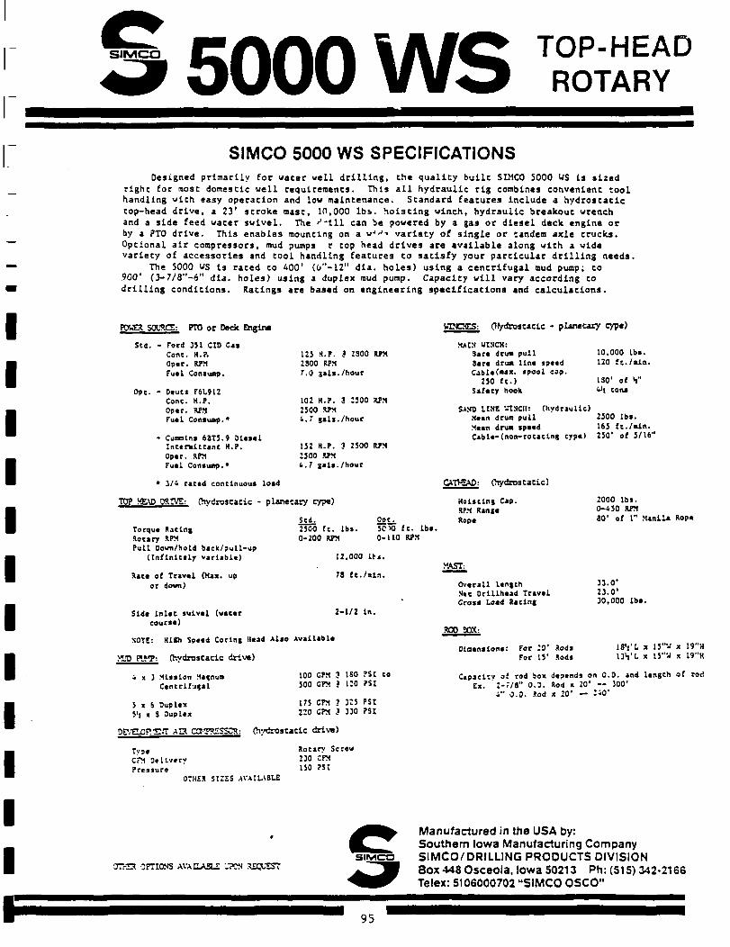
SiMCO 5000 WS TOP-HEAD ROTARY
SIMCO 5000 WS SPECIFICATIONS Designed primari ly for water w e l l d r i l l i n g , Che q u a l i t y b u i l t SIMCO S0O0 WS Is s i z e d
rlghc for most domescic w e l l requiremencs. This a l l hydraul i c r i g combines convenient t o o l handling with easy operat ion and low maintenance. Standard f ea tures inc lude a h y d r o s t a t i c top-head d r i v e , a 23' s t roke mast, 10,000 l b s . h o i s t i n g winch, hydraul i c breakout wrench and a s i d e feed water s w i v e l , the ' ' " i l l can be powered by a gas or d i e s e l deck engine or by a PT0 d r i v e . This enab le s mounting on a «•'<•'•• v a r i e t y of s i n g l e or tandem ax le t rucks . Optional a i r compressors, mud pumps r top head d r i v e s are a v a i l a b l e along with a wide v a r i e t y of a c c e s s o r i e s and t o o l handling f e a t u r e s to s a t i s f y your p a r t i c u l a r d r i l l i n g needs .
The S000 WS i s rated to 400' (0"-12" d i a . h o l e s ) u s ing a c e n t r i f u g a l mud pump; to 900' (3— 7/8"-6" d i a . h o l e s ) using a duplex mud pump. Capacity w i l l vary according to d r i l l i n g c o n d i t i o n s . Ratings are based on e n g i n e e r i n g s p e c i f i c a t i o n s and c a l c u l a t i o n s .
POWta SOCSCS: PTO or Deck Q»gine
Scd. • Ford 351 CID Cas Cone. H.P. 0p«r. RPM Fuel Consuap.
Opt. - D«utt F6L912 Cone. H.P. 0p«r. RPM Fuel Consuap.*
- Cuaalns 63T3.9 Olesel Intermittent H.P. 0p«r. RPM Fuel Consuap.*
WINCTES: (Hydrostatic . planecary type)
125 H.P. 3 2300 RPM 2300 RPM 7.0 gals./hour
102 H.P. 3 2500 RPM 2500 RPM 4.7 gals./hour
152 H.P. 3 2500 RPM 2300 RJPM 4.7 gala. /hour
MAIN WINCH: 3ace drua pull Bart drua Una sp««d Cabie(*ax. spool cap.
250 ft.) Safety hook
10,000 lbs. 120 ft./aln
130' of V 0\ cons
SAND LINE VTNCII: (hydraulic) Mean drua pull 2500 lbs . Mean drua speed 165 f t . /a ln. Cable-(non-rotatlng cyp«) 250' of 5/16"
* 3/4 ratad continuous load
TOP HE\D ORIVS: (hydrostatic - planetary cype)
Torque Rating Rotary RPM Pull Down/hold back/pull-up
(Infinitely variable)
Rata of Travel (Max. up or down)
Slda lnlee swivel (water course)
Scd. 2500 ft. lbs. 0-200 RPM
Pot. 5C10 f t . lbs. 0-110 RPM
12.000 Its .
78 f t . / s in .
2-1/2 in.
CATHEAD: (hydrostatic)
Hoisting Cap. RPM Range Rope
VAST:
Overall length N«c Drlllhead Travel Cross Load Rating
NOTE: Hl»h Spaed Coring Head Also Available
>*JD PIVP: (hydrostatic drive)
300 SOX:
Olnenslons: For 20' Rods For 15' Rods
2000 lbs. 0-450 RPM 80' of 1" Manila Rope
33.0' 23.0' 30,000 l b s .
13'i'L x 13"W x 19"H 13V L x 13"^ x 19"H
4 x 3 Mission Magnua Centrifugal
5 x 6 Duplex 5'i x 3 Ouplex
100 CPM 3 180 ?SI to 500 CPM J 120 ?SI
175 CPM 3 325 PSI 220 CPM J 330 PSI
Capacity of rod box depends on 0 . 0 . and length of rod Ex. 2-7/8" 0 . 3 . Rod x 20' - - 300'
4" 0 .0 . Sod x 20' — 240'
DF/EL0F!S.T A P C3T?£SSCR: (hydrostat ic drive)
TvPt Rotary Screw CPM Oellverv 230 CFM Pressure 130 ? "
OTHER SI2ES AVAILABLE
crr-a OPTIONS AVAEASLZ ;.7CN REQUEST SUVICO
Manufactured in the USA by: Southern Iowa Manufacturing Company SIMCO/DRILLING PRODUCTS DIVISION Box 448 Osceola, Iowa 50213 Ph: (515) 342-2166 Telex: 5106000702 "SIMCO OSCO"
95
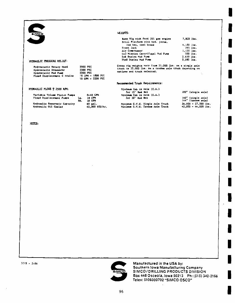
•IMCO viians: s«*« OrlU
Rli
ru with trora
ford with
351 hyd
! • • t n i l m • jacka.
7 820 lbf .
HYDRAULIC PBESSL-RE MLIff:
Rydroatadc Rotary Haad Hydrostatic Drawvorka Hydroacaclc Mud Puap Flxad Dlaplacaaant C rculti
HYDRAULIC FL0U5 1 2500 RW;
Varlabls Voluaa Plaon Puapa Flxad Dlaplacaaant Puopa
Hydraulic Raaarvolr Capiclty Hydraulic Oil Coolar
3000 PSI 2300 PSI 3000 PSI '8 :PM - iaoo PSI IQ CPH - 2200 PSI
t-l-Sa.
0-40 CPM 18 CPM 10 CM «0 | a l . 43,000 ITU/br.
Mini I
Mini Mini
rod box, cool boxaa 4 , .30 Iba. Front Jack 243 Iba. Air Coapraaaar 1,130 Iba. 4«J Mlaalon Cantrlfugal Mud Puap 300 l b t . 3x6 Ouplax Mud Puap 2.650 lb t . 3S*8 Ouplax Mud Puap 3,083 Iba.
Croaa r l | va l thta vary froa 21,000 Iba. on a i l n | l a axla truck ca 33.000 l b t . on a tandaa »xla truck dapandlnf on optlona and truck la laccad .
Raccomndad Truck Requirements:
Mlnlaua Cab to Axla (C.A.) for 13' Rod Sox
Cab to Axla (C.A.) (or 20' Rod Box
CV.il. S lnf la Axla Truck C.V.W. Tandaa Axla Truck
102" ( . I n t l . axla)
160" ( i l n f l a axla) 144" (tandaa axla) 26.000 - 27.300 Iba. 42,000 - 44,000 Iba.
OTES:
30VS - 3i86
SUV1CO
Manufactured in the USA by: Southern Iowa Manufacturing Company SIMCO/DRILLING PRODUCTS DIVISION Box 448 Osceola, Iowa 50213 Ph: (515) 342-2166 Telex: 5106000702 "SIMCO OSCO"
96
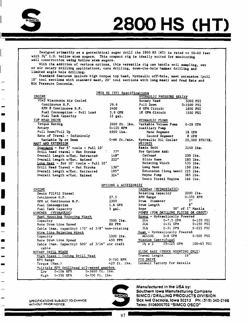
8IMCO 2800 HS CHT) Designed primarily as a geocechnlcal auger drill Che 2800 HS (HT) Is rated Co 50-60 feec
with 3V I.D. hollow seem augers. This compact rig is ideally suited for monitoring well construction using hollow stem augers.
With the addition of various options, this versatile rig can handle soil sampling, wet or air rotary drilling applications, core drilling, down-che-hole hammer drilling and limited angle hole drilling.
Standard features include high torque top head, hydraulic off-hole, mast extension (pull 10' tool sections with standard mast, 20' tool sections with long mast) and Feed Rate and Bit Pressure Controls.
2800 HS (HT) Specifications ENGINE
VG4D Wisconsin Air Cooled Continuous H.P. RPM @ Continuous H.P. Fuel Consumption - Full Load Fuel Tank Capacity
TOP HEAD DRIVE Torque Rating Rotary Pull Down/Pull Up Rate of Travel - Infinitely
Variable Up or Down MAST AND EXTENSION
Standard - for 5' tools - Pull 10' Drill head travel - Net Stroke Overall Length w/Ext. Retracted Overall Length w/Ext. Raised Long Mast - for 10' tools - Pull 20' Drill Head Travel - Net Stroke Overall Length w/Ext. Retracted Overall Length w/Ext. Raised
29.6 2400 3.9 GPH 15 gal.
3500 ft. lbs. 0-120 RPM 6500 lbs.
0-66 ft./min.
77" 148" 222"
130" 195" 324"
HYDRAULIC PRESSURE RELIEF Rotary Head 5000 PSI Pull Down 0-1500 PSI 8 GPM Circuit 1800 PSI 18 CPM Circuit 1500 PSI
HYDRAULIC FLOWS Variable Volume Pump Auxiliary Pump
Main Segment Second Segment
Hydraulic Oil Cooler WEIGHTS Basic Unit For Options Add: Cathead 200 Slide Base 185 Hoisting Winch 135 Long Mast 150 Extension (long mast) 225 Moyno Pump 385 Deutz Diesel Engine 166
0-28 GPM
18 GPM 8 GPM
20,000 BTU/HR.
3140 lbs.
lbs. lbs. lbs. lbs. lbs. lbs. lbs.
OPTIONS & ACCESSORIES
ENGINE Deutz F2L912 Diesel Continuous H.P. RPM at Continuous H.P. Fuel Consumption Fuel Tank Capacity
WINCHES (HYDRAULIC) Mast Mounting Hoisting Winch
2 7 . 5 2300 1.6 GPH 5 g a l .
3500 l b s . 80 FPM
of 3 / 8 " n o n - r o t a t i n g
Capacity Bare Drum Line Speed Cable (max. capacity) 170 Wire Line Hoisting Winch Capacity Bare Drum Line Speed Cable (Max. Capacity) 500
cable ROTARY DRILL HEADS High Speed - Coring Drill Head RPM Range 0-700 RPM Torque (Max.) 420 ft. lbs. Multiple RPM Drillhead w/2-speed gearbox
1000 lbs. 450 FPM
of 3/16" air craft
CATHEAD (HYDROSTATIC) Hoisting Capacity 2000 lbs. RPM Range 0-335 RPM Drum Diameter 7" Drum Length 8" Rope 50* of 1" Manila PUMPS (FOR DRILLING FLUIDS OR GROUT) Movno - Hydraulically Powered
2L4 0-7.5 GPM 0-120 PSI 2L6 0-31 GPM 0-150 PSI 3L6 0-31 GPM 0-225 PSI
Bean - Hydraulically Powered AC410C 0-8 GPM 0-500 PSI
Mission Centrifugal lh x 2 25-125 CPM 100-65 PSI
SLIDE BASE (TRUCK MOUNTING ONLY) Travel Length 16" PTO DRIVE Consult Factory for details
Low High
0-106 RPM 0-550 RPM
0-3600 0-700 f
f t . l b s . t . l b s .
SPECIFICATIONS SUBJECT TO CHANGE WITHOUT PRIOR NOTICE.
Manufactured in the USA by: Southern Iowa Manufacturing Company S1MCO/DRILLJNG PRODUCTS DIVISION Sox 443 Osceola, Iowa 50213 Ph: (515) 342-2166 Telex: 5106000702 "S1MCO OSCO"
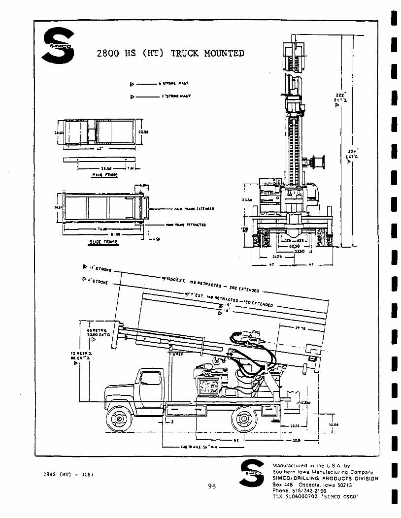
8 I M C O
2800 HS (HT) TRUCK MOUNTED F?
rm U- w
IZi*
H.U U.U Htm mint
1 • < ^
-nua ratMi (ITTNOIO
• i i j » -— — — I I M •
SUM rwt
• mm nui| *m«cTio
> n *~r*0*t
'''*T»OKE
3^T-- —li»
not
-GMTBji ic St 'niM
28HS (HT) - 0187
93
Manufactured m the U S A by Southern Iowa Manufacturing Company SIMCO/ORILLING PRODUCTS DIVISION Box 4<8 Osceola, icwa 50213 Pnone: 515/342-2166 TLX 5106000702 'SIMC0 0SC0'
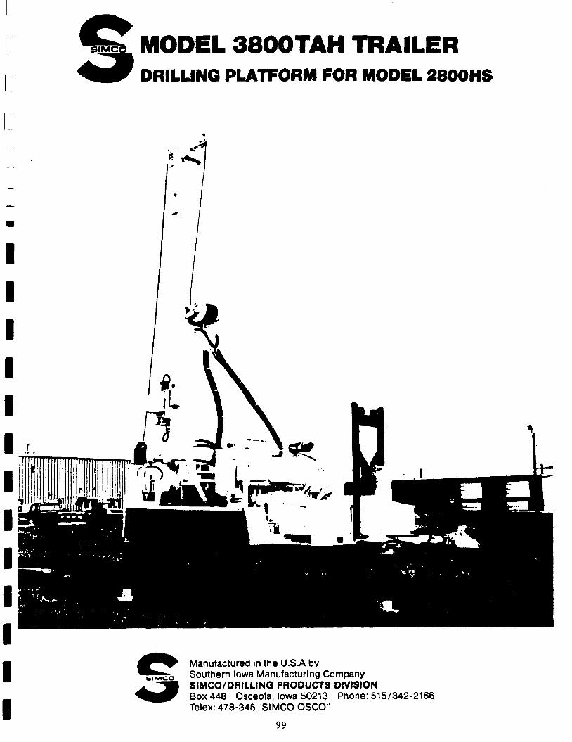
MODEL 3800TAH TRAILER DRILLING PLATFORM FOR MODEL 2800HS
Manufactured in the U.S.A by siiyico Southern Iowa Manufacturing Company
SIMCO/DRILLING PRODUCTS DIVISION Box 448 Osceola, Iowa 50213 Phone: 515/342-2166 Telex: 478-345 "SIMCO OSCO"
99
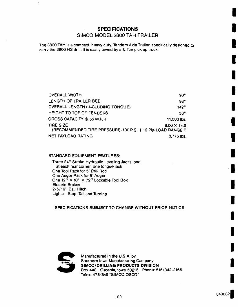
SPECIFICATIONS SIMCO MODEL 3800 TAH TRAILER
The 3800 TAH is a compact, heavy duty, Tandem Axle Trailer, specifically designed to carry the 2800 HS drill. It is easily towed by a % Ton pick up truck.
OVERALL WIDTH 90" LENGTH OF TRAILER BED 98" OVERALL LENGTH (INCLUDING TONGUE) 142" HEIGHT TO TOP OF FENDERS 33" GROSS CAPACITY @ 55 M.P.H. 11.000 lbs. TIRE SIZE 8:00X14.5
(RECOMMENDED TIRE PRESSURE-100 P.S.I.) 12 Ply-LOAD RANGE F NET PAYLOAD RATING 8.775 lbs.
STANDARD EQUIPMENT FEATURES: Three 24" Stroke Hydraulic Leveling Jacks, one
at each rear corner, one tongue jack One Tool Rack for 5' Drill Rod One Auger Rack for 5' Auger One 12" X 10" X 72" LockableTool Box Electric Brakes 2-5/16" Ball Hitch Lights—Stop, Tail and Turning
SPECIFICATIONS SUBJECT TO CHANGE WITHOUT PRIOR NOTICE
S I M C O
Manufactured in the U.S.A. by Southern Iowa Manufacturing Company SIMCO/DRILLING PRODUCTS DIVISION Box 448 Osceola, Iowa 50213 Phone: 515/342-2166 Telex: 478-345 "SIMCO OSCO"
100 040682

APPENDIX I
Failing Literature
- 101 -

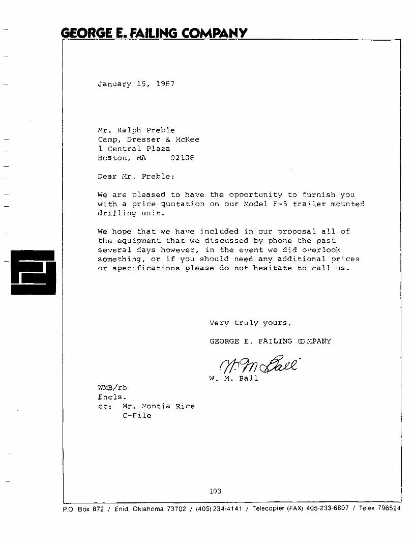
GEORGE E. FAILING COMPANY
January 15, 1987
Mr. Ralph Preble Camp, Dresser & McKee 1 Central Plaza Boston, MA 0210F
Dear Mr. Preble:
We are pleased to have the opportunity to furnish you with a price quotation on our Model F-5 trailer mounted drilling unit.
We hope that we have included in our proposal all of the equipment that we discussed by phone the past several days however, in the event we did overlook something, or if you should need any additional prices or specifications please do not hesitate to call us.
Very truly yours,
GEORGE E. FAILING COMPANY
W. M. Ball WMB/rb Ends. cc: Mr. Montia Rice
C-File
P.O. Box 872 / Enid, Oklahoma 73702 / (405)234-4141 / Telecopier (FAX) 405-233-6807 / Telex 796524
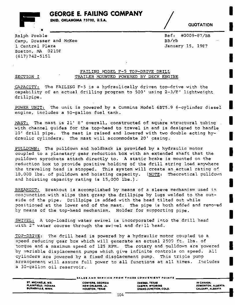
GEORGE E. FAILING COMPANY ENID, OKLAHOMA 73702, U.S.A.
QUOTATION
Ralph Preble Ref: #0009-87/3B Camp, Dresser and McKee BB/rb 1 Central Plaza January 15, 1987 Boston, MA 02108 (617)742-5151
FAILING MODEL F-5 TOP-DRIVE DRILL SECTION I TRAILER MOUNTED POWERED BY DECK ENGINE
CAPACITY: The FAILING F-5 is a hydraulically driven top-drive with the capability of an actual drilling program to 500' using 2-3/8" lightweight drillpipe.
POWER UNIT: The unit is powered by a Cummins Model 6BT5.9 6-cylinder diesel engine, includes a 50-gallon fuel tank.
MAST: The mast is 21' 8" overall, constructed of square structural tubing with channel guides for the top-head to travel in and is designed to handle 10* drill pipe. The mast is raised and lowered with two double acting hydraulic cylinders. The mast will accommodate 20' casing.
PULLDOWN: The pulldown and holdback is provided by a hydraulic motor coupled to a planetary gear reduction box with an extended shaft that the pulldown sprockets attach directly to. A static brake is mounted on the reduction box to provide positive holding of the drill string load anywhere the traveling head is stopped. This system will create an actual rating of 10,000 lbs. of pulldown and hoisting capacity. (NOTE: Theoretical pulldown and hoisting capacity rating is 15,000 lbs.).
BREAKOUT: Breakout is accomplished by means of a sleeve mechanism used in conjunction with slips that grasp the drillpipe by lugs welded to the outside of the pipe. Drillpipe is added with the head tilted out while positioned at the lower end of the mast. The pipe is both added and removed by means of the top-head mechanism. Holder for supporting pipe.
SWIVEL: A top-loading water swivel is incorporated into the drill head with 2" water course through the swivel and drill head.
TOP-DRIVE: The drill head is powered by a hydraulic motor coupled to a speed reducing gear box which will generate an actual 2500 ft. lbs. of torque and a maximum speed of 125 RPM. The rotary and pulldown are powered by variable displacement pumps which give infinite controls on speed. All cylinders are powered by a fixed displacement pump. This triple pump arrangement will assure full power to all functions at all times. Includes a 30-gallon oil reservoir.
SALES A N D S E R V I C E P R O M T H E S E C O N V E N I E N T P O I N T S
ST. MICHAELS. MO. CONVERS, GEORGIA ODESSA. TEXAS IN CANAOA: PLAINFIELD, INDIANA NEW ORLEANS. LA. CASPER. WYOMING EDMONTON. ALBERTA BURNSVILLS, MINN. HOUSTON. TEXAS GRAND JUNCTION, COLO. CALGARY, ALBERTA
104
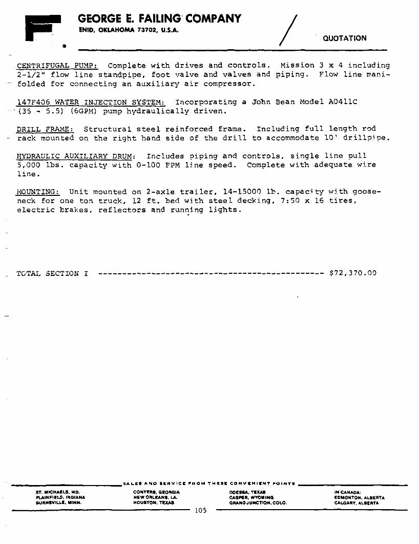
GEORGE E. FAILING COMPANY ENID, OKLAHOMA 73702, U.S.A.
QUOTATION
CENTRIFUGAL PUMP; Complete with drives and controls. Mission 3 x 4 including 2-1/2" flow line standpipe, foot valve and valves and piping. Flow line manifolded for connecting an auxiliary air compressor.
147F406 WATER INJECTION SYSTEM: Incorporating a John Bean Model A0411C (35 - 5.5) (6GPM) pump hydraulically driven.
DRILL FRAME: Structural steel reinforced frame. Including full length rod rack mounted on the right hand side of the drill to accommodate 10' drillpipe.
HYDRAULIC AUXILIARY DRUM: Includes piping and controls, single line pull 5,000 lbs. capacity with 0-100 FPM line speed. Complete with adequate wire line.
MOUNTING: Unit mounted on 2-axle trailer, 14-15000 lb. capacity with gooseneck for one ton truck, 12 ft. bed with steel decking, 7:50 x 16 tires, electric brakes, reflectors and running lights.
TOTAL SECTION I $72,370.00
S A L E S A N D S E R V I C E F R O M T H E S E C O N V E N I E N T P O I N T S
ST. MICMACLS. MO. PLAINFIELO. INOIANA BURNSVILLS, MINN.
CONYERS. GEORGIA NEW ORLEANS. LA. HOUSTON, TEXAS
OOESSA, TEXAS CASPER. WYOMING QRANO JUNCTION. COLO.
IN CANADA: EDMONTON. ALBERTA CALGARY. ALBERTA
105
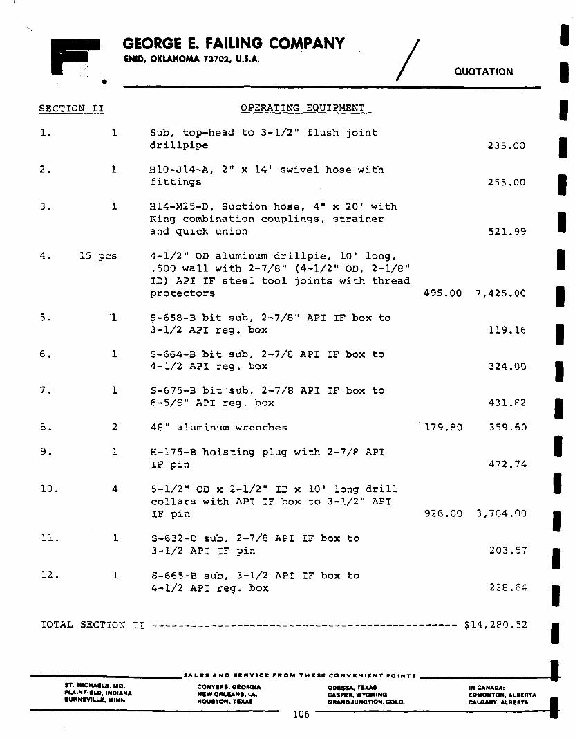
GEORGE E. FAILING COMPANY ENID, OKLAHOMA 73702, U.S.A.
QUOTATION
SECTION I I
1 . 1
OPERATING EQUIPMENT
S u b , t o p - h e a d t o 3 - 1 / 2 " f l u s h j o i n t d r i l l p i p e 235.00
2. 1 H10-J14-A, 2" x 14' swivel hose with fittings
3. 1 H14-M25-D, Suction hose, 4" x 20' with King combination couplings, strainer and quick union
4. 15 pes 4-1/2" OD aluminum drillpie, 10' long, .500 wall with 2-7/8" (4-1/2" OD, 2-1/8" ID) API IF steel tool joints with thread protectors
5. 1 S-658-3 bit sub, 2-7/8" API IF box to 3-1/2 API reg. box
6. 1 S-664-B bit sub, 2-7/8 API IF box to 4-1/2 API reg. box
7. 1 S-675-B bit sub, 2-7/8 API IF box to
6-5/6" API reg. box
6. 2 48" aluminum wrenches
9. 1 H-17 5-B hoisting plug with 2-7/8 API IF pin
10. 4 5-1/2" OD x 2-1/2" ID x 10' long drill collars with API IF box to 3-1/2" API IF pin
11. 1 S-632-D sub, 2-7/8 API IF box to 3-1/2 API IF pin
12. 1 S-665-B sub, 3-1/2 API IF box to 4-1/2 API reg. box
255.00
521.99
495.00 7,425.00
119.16
324.00
431.F2
179.80 359.60
472.74
926.00 3,704.00
203.57
228.64
TOTAL SECTION II $14,280.52
ST. MICHAELS, MO. PLAINFIELO, INDIANA BURNSVILLI, MINN.
SALES A N D SKRVICK P R O M T H I I I C O N V E N I E N T P O I N T S
CONYERS, aeoraiA NEW ORLEANS. LA. HOUSTON, TEXAS
ODESSA, TEXAS CASPER. WYOMING GRAND JUNCTION, COLO.
106
IN CANADA: EDMONTON, ALBERTA CALGARY, ALBERTA
4 4
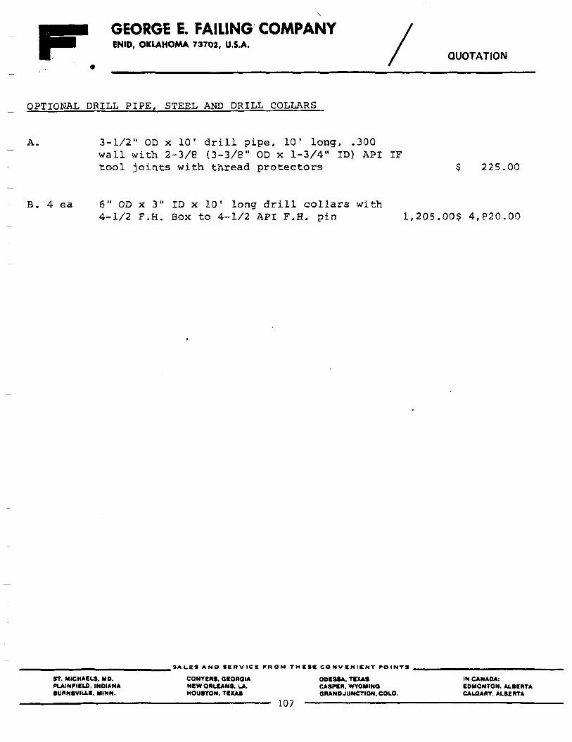
GEORGE E. FAILING COMPANY ENID, OKLAHOMA 73702, U.S.A.
QUOTATION
OPTIONAL DRILL PIPE, STEEL AND DRILL COLLARS
A. 3-1/2" OD x 10' drill pipe, 10' long, .300 wall with 2-3/8 (3-3/8" OD x 1-3/4" ID) API IF tool joints with thread protectors $ 225.00
B. 4 ea 6" OD x 3" ID x 10' long drill collars with 4-1/2 F.H. Box to 4-1/2 API F.H. pin 1,205.00$ 4,820.00
SALES A N D S E R V I C E PROM T H E S E C O N V E N I E N T P O I N T S
ST. MICHAELS. MD. CONYERS. GEORGIA OOESSA, TEXAS IN CANADA: PIAINFIELD, INDIANA NEW ORLEANS, LA. CASPER. WYOMING E0MONTON. ALBERTA BUAN8VIU.fi, MINN. HOUSTON, TEXAS GRANO JUNCTION, COLO. CALGARY, ALBERTA
107
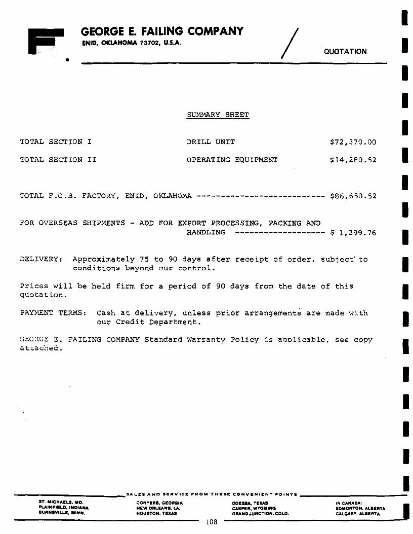
GEORGE E. FAILING COMPANY ENID, OKLAHOMA 73702, U.S.A.
QUOTATION
SUMMARY SHEET
TOTAL SECTION I DRILL UNIT $72,370.00
TOTAL SECTION II OPERATING EQUIPMENT $14,2P0.52
TOTAL F.O.B. FACTORY, ENID, OKLAHOMA $86,650.52
FOR OVERSEAS SHIPMENTS - ADD FOR EXPORT PROCESSING, PACKING AND HANDLING $ 1,299.76
DELIVERY: Approximately 75 to 90 days after receipt of order, subject' to conditions beyond our control.
Prices will be held firm for a period of 90 days from the date of this quotation.
PAYMENT TERMS: Cash at delivery, unless prior arrangements are made with our Credit Department.
GEORGE E. FAILING COMPANY Standard Warranty Policy is applicable, see copy attached.
SALES A N D S E R V I C E PROM T H E S E C O N V E N I E N T POINTS
ST. MICHAELS, MO. CONYERS, GEORGIA ODESSA, TEXAS IN CANAOA: PLAINRIELD, INDIANA NEW ORLEANS. LA. CASPER. WYOMING EDMONTON, ALBERTA SURNSVILLE, MINN. HOUSTON, TEXAS GRANO JUNCTION. COLO. CALGARY. ALBERTA
108
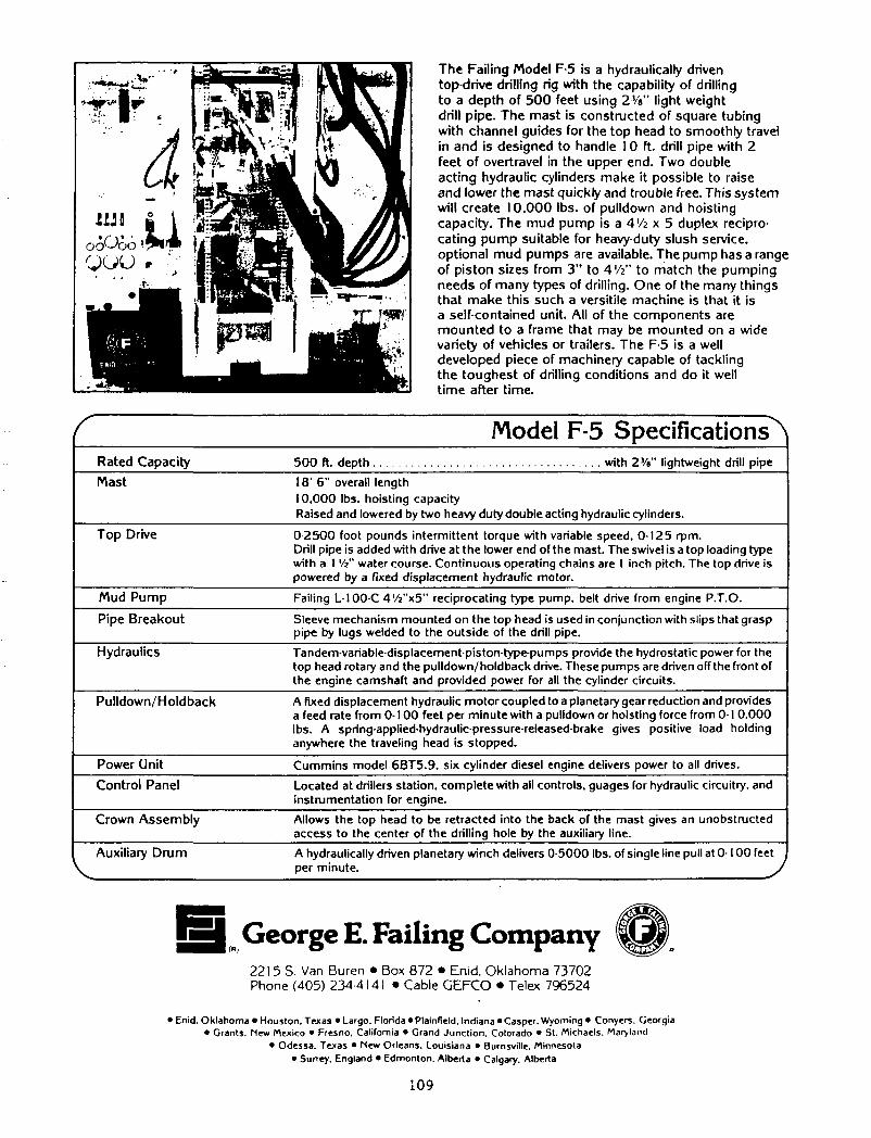
The Fai l ing Model F-5 is a hydraulically driven top-drive dril l ing rig with the capability of drill ing to a depth of 5 0 0 feet using 23/8" l ight weight dril l p ipe. The mast is const ructed of square tub ing with channel guides for the top head to smooth ly travel in and is designed to handle 10 ft. drill pipe with 2 feet of overtravel in the upper end. Two double act ing hydraulic cylinders make it possible to raise and lower the mast quickly and trouble free. This sys tem will create 10 ,000 lbs. of pul ldown and hoist ing capacity. The m u d p u m p i s a 4 ' / j x 5 duplex reciprocat ing p u m p suitable for heavy-duty slush service, opt ional m u d pumps are available. The pump has a range of p is ton sizes f rom 3 " to 4'/i" to match the pump ing needs of many types of dri l l ing. One of the many things that make this such a versitile machine is that it is a self-contained unit. All of the components are m o u n t e d to a frame that may be mounted on a wide variety of vehicles or trailers. The F-5 is a well developed piece of machinery capable of tackl ing the toughest of dril l ing condi t ions and do it well t ime after t ime.
Model F-5 Specifications"^ Rated Capacity 500 ft. depth with 2V»" lightweight drill pipe
Mast 18' 6" overall length 10.000 lbs. hoisting capacity Raised and lowered by two heavy duty double acting hydraulic cylinders.
Top Drive 0 2500 foot pounds intermittent torque with variable speed, 0-125 rpm. Drill pipe is added with drive at the lower end of the mast. The swivel is a top loading type with a 1 W water course. Continuous operating chains are I inch pitch. The top drive is powered by a fixed displacement hydraulic motor.
Mud Pump Failing L100-C 4'/2"x5" reciprocating type pump, belt drive from engine P.T.O.
Pipe Breakout Sleeve mechanism mounted on the top head is used in conjunction with slips that grasp pipe by lugs welded to the outside of the drill pipe.
Hydraulics Tandem-variable-displacement-piston-type-pumps provide the hydrostatic power for the top head rotary and the pulldown/ holdback drive. These pumps are driven off the front of the engine camshaft and provided power for all the cylinder circuits.
Pul ldown/Holdback A fixed displacement hydraulic motor coupled to a planetary gear reduction and provides a feed rate from 0-100 feet per minute with a pulldown or hoisting force from 0-1 0.000 lbs. A spring-applied-hydraulic-pressure-released-brake gives positive load holding anywhere the traveling head is stopped.
Power Unit Cummins model 6BT5.9. six cylinder diesel engine delivers power to all drives.
Control Panel Located at drillers station, complete with all controls, guages for hydraulic circuitry, and instrumentation for engine.
Crown Assembly Allows the top head to be retracted into the back of the mast gives an unobstructed access to the center of the drilling hole by the auxiliary line.
Auxiliary D r u m A hydraulically driven planetary winch delivers 0-5000 lbs. of single line pull at 0-100 feet . per minute. J
George E. Failing Company 221 5 S. Van Buren • Box 872 • Enid, Ok lahoma 73702 Phone (405) 234 4141 • Cable GEFCO • Telex 796524
• Enid. Oklahoma • Houston. Texas • Largo. Florida • Plainfield. Indiana • Casper. Wyoming • Conyers. Georgia • Grants. Mew Mexico • Fresno. California • Grand Junction, Colorado • St. Michaels. Maryland
• Odessa. Texas • New Orleans. Louisiana • Burnsville. Minnesota • Surrey. England • Edmonton. Alberta • Calgary. Alberta
109

APPENDIX J
Gus Pech Literature
- Ill -

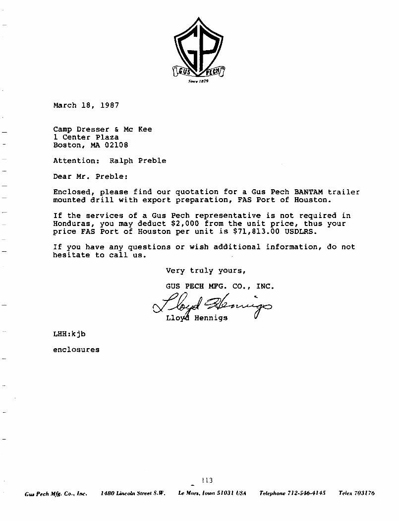
Star* 1879
March 1 8 , 1987
Camp Dresser & Mc Kee 1 Center Plaza Boston, MA 02108
Attention: Ralph Preble
Dear Mr. Preble:
Enclosed, please find our quotation for a Gus Pech BANTAM trailer mounted drill with export preparation, FAS Port of Houston.
If the services of a Gus Pech representative is not required in Honduras, you may deduct $2,000 from the unit price, thus your price FAS Port of Houston per unit is $71,813.00 USDLRS.
If you have any questions or wish additional information, do not hesitate to call us.
Very truly yours,
GUS PECH MFG. CO., INC.
Lloyd Hennigs V Lloyd Hennigs
LHH:kjb
enclosures
113
Gut Pech Mfg. Co., Inc. 1480 Lincoln Street S.W. Le Murs, Iowa 51031 USA Telephone 712-546-4145 Telex 703176
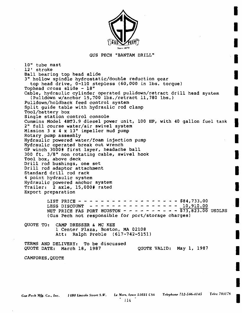
Sim-.' 1879
GUS PECH "BANTAM DRILL"
10" tube mast 12' stroke Ball bearing top head slide 3" hollow spindle hydrostatic/double reduction gear top head drive, 0-110 stepless (60,000 in lbs. torque)
Tophead cross slide - 18" Cable, hydraulic cylinder operated pulldown/retract drill head system
(Pulldown w/anchor 15,700 lbs./retract 11,780 lbs.) Pulldown/holdback feed control system Split guide table with hydraulic rod clamp Tool/battery box Single station control console Cummins Model 4BT3.9 diesel power unit, 100 HP, with 40 gallon fuel tank 2" full course water/air swivel system Mission 3 x 4 x 13" impeller mud pump Rotary pump assembly Hydraulic powered water/foam injection pump Hydraulic operated break out wrench GP winch 3000# first layer, headache ball 300 ft. 3/8" non rotating cable, swivel hook Tool box, above deck Drill rod bushings, one set Drill rod adaptor attachment Standard drill rod rack 4 point hydraulic system Hydraulic powered anchor system Trailer: 2 axle, 15,000# rated Export preparation
LIST PRICE _ _ _ _ - $84,733.00 LESS DISCOUNT 10,910.00 NET PRICE FAS PORT HOUSTON $73,823.00 USDLRS (Gus Pech not responsible for port/storage charges)
QUOTE TO: CAMP DRESSER & MC KEE 1 Center Plaza, Boston, MA 02108 Att: Ralph Preble (617-742-5151)
TERMS AND DELIVERY: To be discussed QUOTE DATE: March 18, 1987 QUOTE VALID: May 1, 1987
CAMPDRES.QUOTE
Gut Pech Mfg. Co., Inc. 1480 Lincoln Street S.W. Le Wars, loica 51031 ISA Telephone 712-546-4145
114
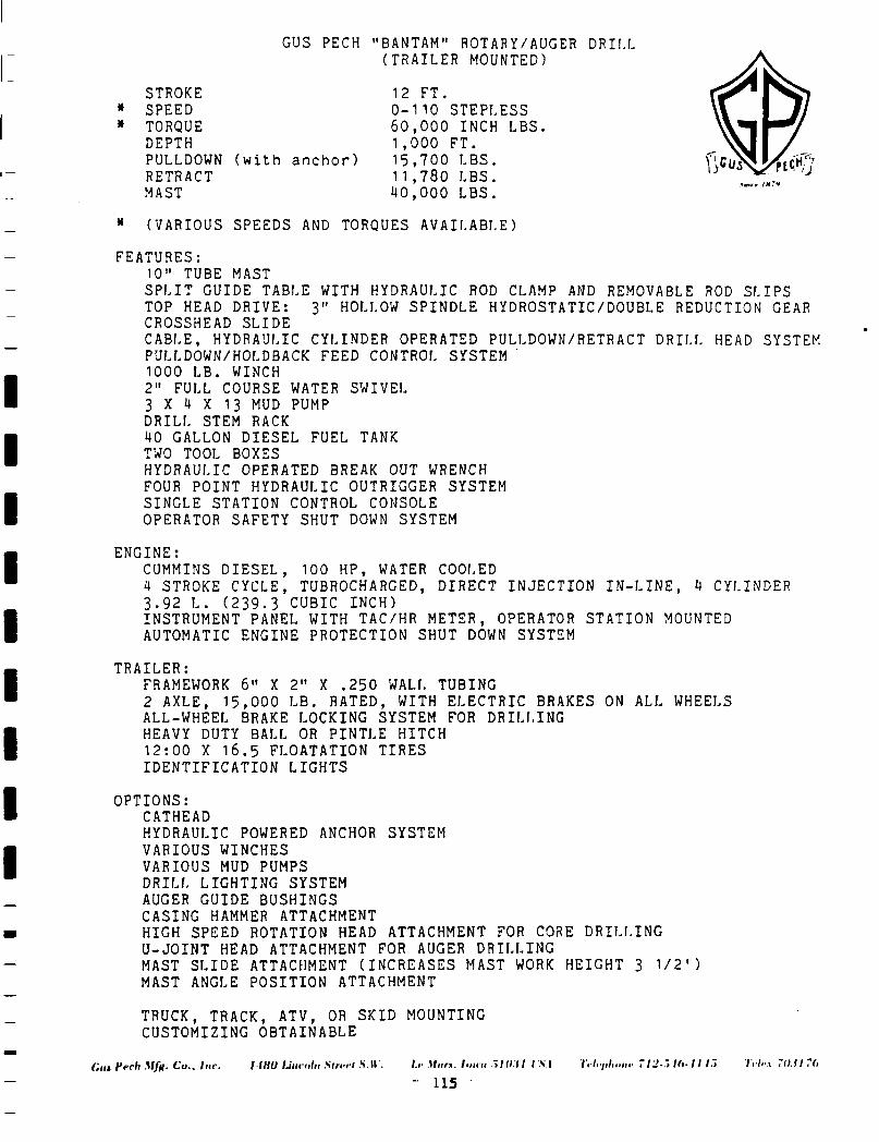
STROKE * SPEED * TORQUE
DEPTH PULLDOWN RETRACT MAST
* (VARIOUS SPEEDS AND TORQUES AVAILABLE)
FEATURES: 10" TUBE MAST SPLIT GUIDE TABLE WITH HYDRAULIC ROD CLAMP AND REMOVABLE ROD SLIPS TOP HEAD DRIVE: 3" HOLLOW SPINDLE HYDROSTATIC/DOUBLE REDUCTION GEAR CROSSHEAD SLIDE CABLE, HYDRAULIC CYLINDER OPERATED PULLDOWN/RETRACT DRILL HEAD SYSTEM PULLDOWN/HOLDBACK FEED CONTROL SYSTEM 1000 LB. WINCH 2" FULL COURSE WATER SWIVEL 3 X 4 X 13 MUD PUMP DRILL STEM RACK 40 GALLON DIESEL FUEL TANK TWO TOOL BOXES HYDRAULIC OPERATED BREAK OUT WRENCH FOUR POINT HYDRAULIC OUTRIGGER SYSTEM SINGLE STATION CONTROL CONSOLE OPERATOR SAFETY SHUT DOWN SYSTEM
ENGINE: CUMMINS DIESEL, 100 HP, WATER COOLED 4 STROKE CYCLE, TUBROCHARGED, DIRECT INJECTION IN-LINE, 4 CYLINDER 3.92 L. (239.3 CUBIC INCH) INSTRUMENT PANEL WITH TAC/HR METER, OPERATOR STATION MOUNTED AUTOMATIC ENGINE PROTECTION SHUT DOWN SYSTEM
TRAILER: FRAMEWORK 6" X 2" X .250 WALL TUBING 2 AXLE, 15,000 LB. RATED, WITH ELECTRIC BRAKES ON ALL WHEELS ALL-WHEEL BRAKE LOCKING SYSTEM FOR DRILLING HEAVY DUTY BALL OR PINTLE HITCH 12:00 X 16.5 FLOATATION TIRES IDENTIFICATION LIGHTS
OPTIONS: CATHEAD HYDRAULIC POWERED ANCHOR SYSTEM VARIOUS WINCHES VARIOUS MUD PUMPS DRILL LIGHTING SYSTEM AUGER GUIDE BUSHINGS CASING HAMMER ATTACHMENT HIGH SPEED ROTATION HEAD ATTACHMENT FOR CORE DRILLING U-JOINT HEAD ATTACHMENT FOR AUGER DRILLING MAST SLIDE ATTACHMENT (INCREASES MAST WORK HEIGHT 3 U2') MAST ANGLE POSITION ATTACHMENT
TRUCK, TRACK, ATV, OR SKID MOUNTING CUSTOMIZING OBTAINABLE
/.<• Vnr.v hum -tlll.il r.S.| 7,7.7,/,,1/ir 712-7, Hi-11 II V . / .v 7<>M7(>
- 115
GUS PECH "BANTAM" ROTARY/AUGER DRILL (TRAILER MOUNTED)
12 FT. 0-110 STEPLESS 6 0 , 0 0 0 INCH LBS, 1 ,000 FT. 15 ,700 LBS. 11 ,780 LBS. 4 0 , 0 0 0 LBS.
(with anchor) >«rr IH7*
(„i, Pvch Mfn- Co., Inc. I IHU Lincoln Slrrrl .S.U .
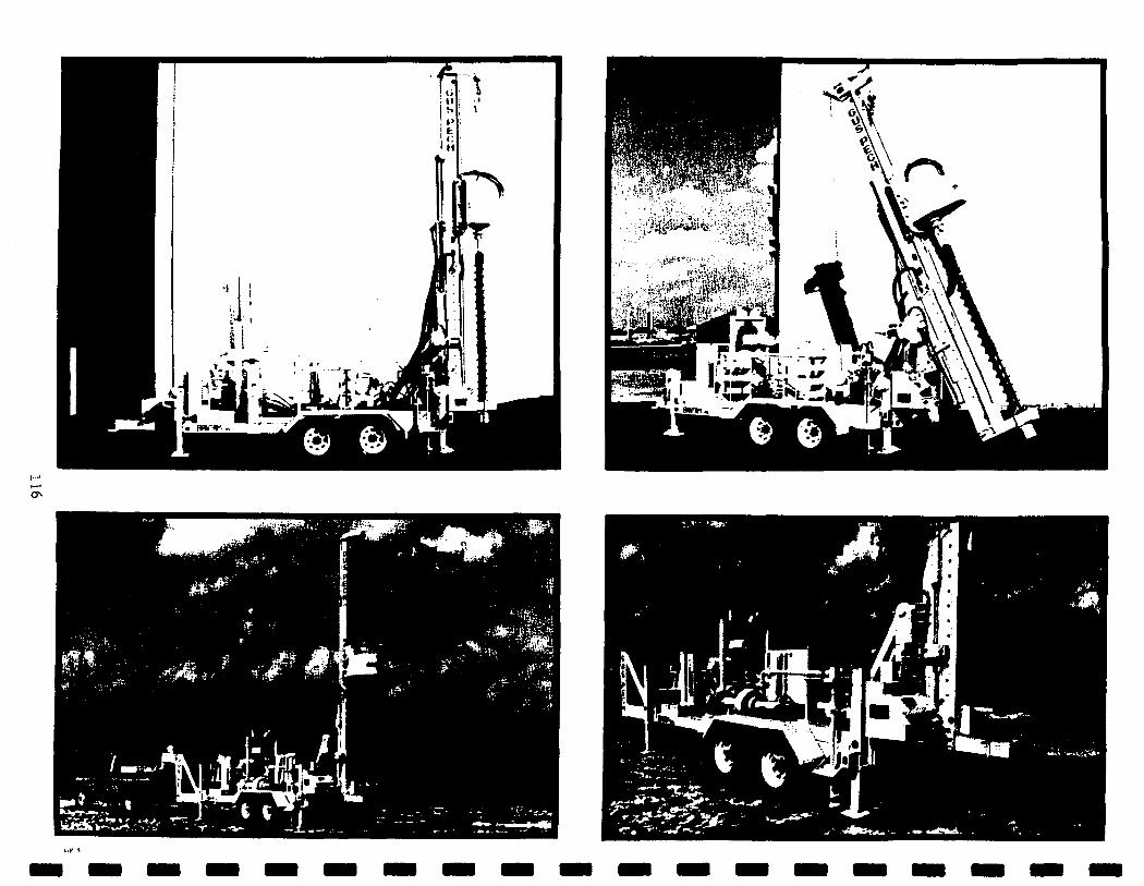
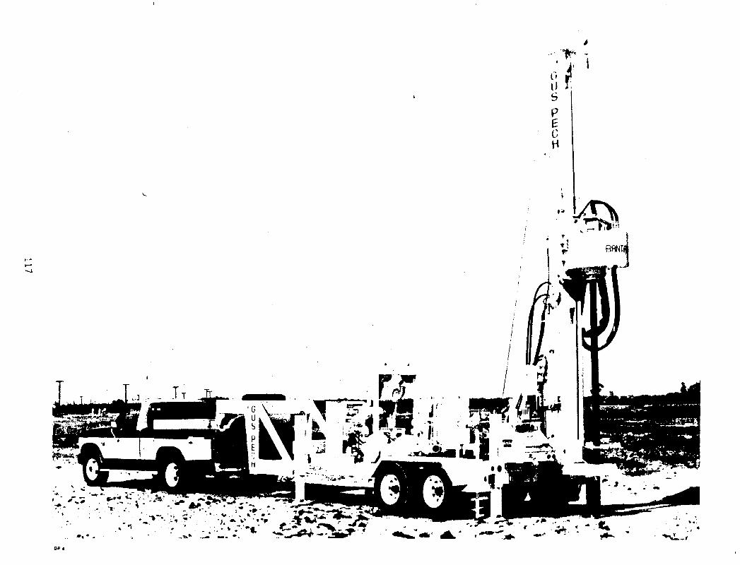
'+.'•"*
'.."*• ->V • v . .. k - » *
*
t
P
o H
- * *
APPENDIX K
Mobile Literature
- 119 -

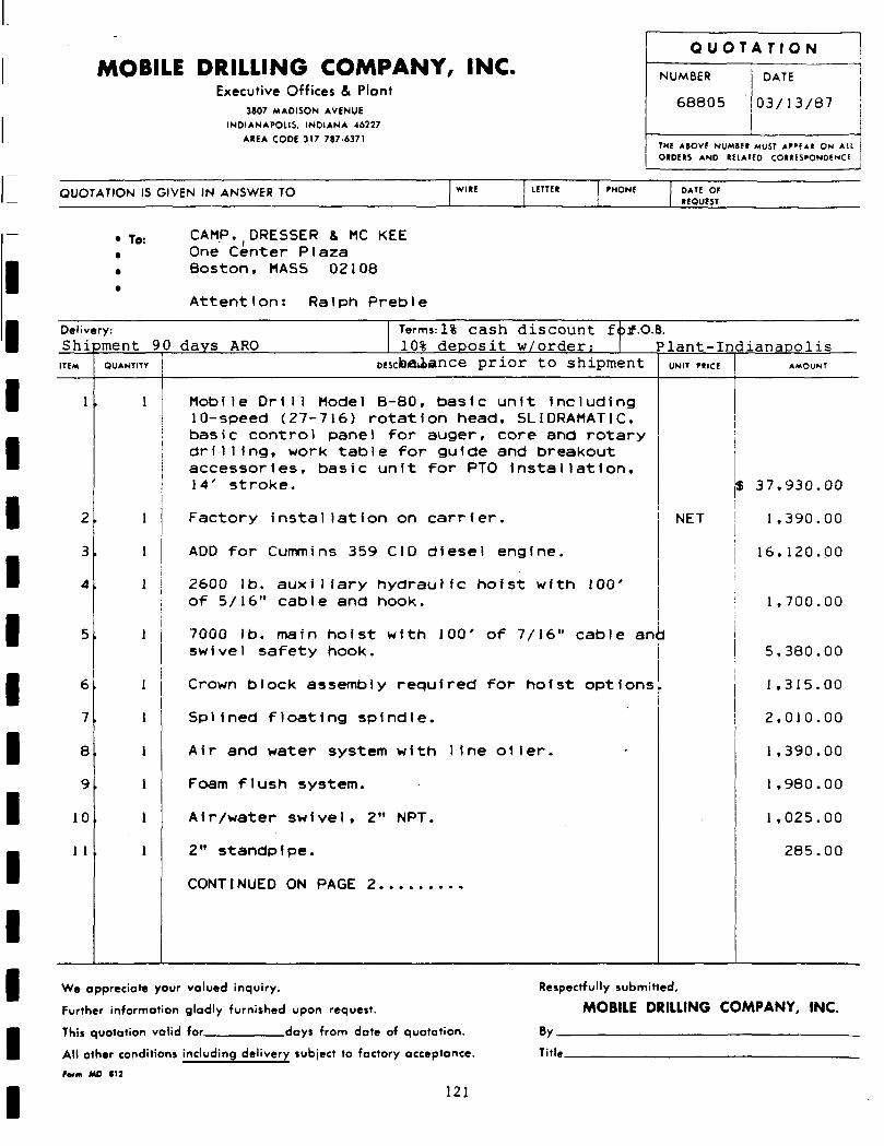
MOBILE DRILLING COMPANY, INC. Executive Offices & Plant
3807 MADISON AVENUE
INDIANAPOLIS. INDIANA 46227
AHEA CODE 317 787-6371
Q U O T A T I O N
NUMBER
68805
DATE
! 0 3 / 1 3 / 8 7
THE A»OVf NUMte* MUST A f ' f A t ON Al l OtDEtS AND tElATCO CO««ES>ON0ENCE
QUOTATION IS GIVEN IN ANSWER TO PHONE DATE OF IBOUfST
• To: CAMP,(DRESSER & MC KEE One Center Plaza Boston, MASS 02108
Attention: Ralph Preble
Delivery:
Shipment 9 0 days ARO ITEM
1
2
3
4
5
6
7
8
9
10
1 1
QUANTITY
1
]
l
Terms: 1% cash discount fotf.O.B. 10% deposit w/order; Plant-In
oEscbaiance prior to shipment
Mobile Drill Model B-80, basic unit Including 10-speed (27-716) rotation head, SLI DRAMATIC, basic control pane) for auger, core and rotary drilling, work table for guide and breakout accessories, basic unit for PTO installation, 14' stroke.
Factory installation on carrier.
ADD for Cummins 359 CID diesel engine.
2600 lb. auxiliary hydraulic hoist with 100' of 5/16" cable and hook.
7000 lb. main hoist with 100' of 7/16" cable arn swivel safety hook.
Crown block assembly required for hoist options
Splined floating spindle.
Air and water system with line oiler.
Foam flush system.
Air/water swivel, 2" NPT.
2" standpipe.
UNIT PtICE
NET
i
'
dianaoolis AMOUNT
$ 37,930.00
1 ,390.00
16,120.00
1 ,700.00
5,380.00
1 ,315.00
2,010.00
1,390.00
1,980.00
1,025.00
285.00
We appreciate your valued inquiry.
Further information gladly furnished upon request.
This quotation valid for days from dote of quotation.
All other conditions including delivery subject to factory acceptance.
farm MO (12
121
Respectfully submitted,
MOBILE DRILLING COMPANY, INC.
By
Title
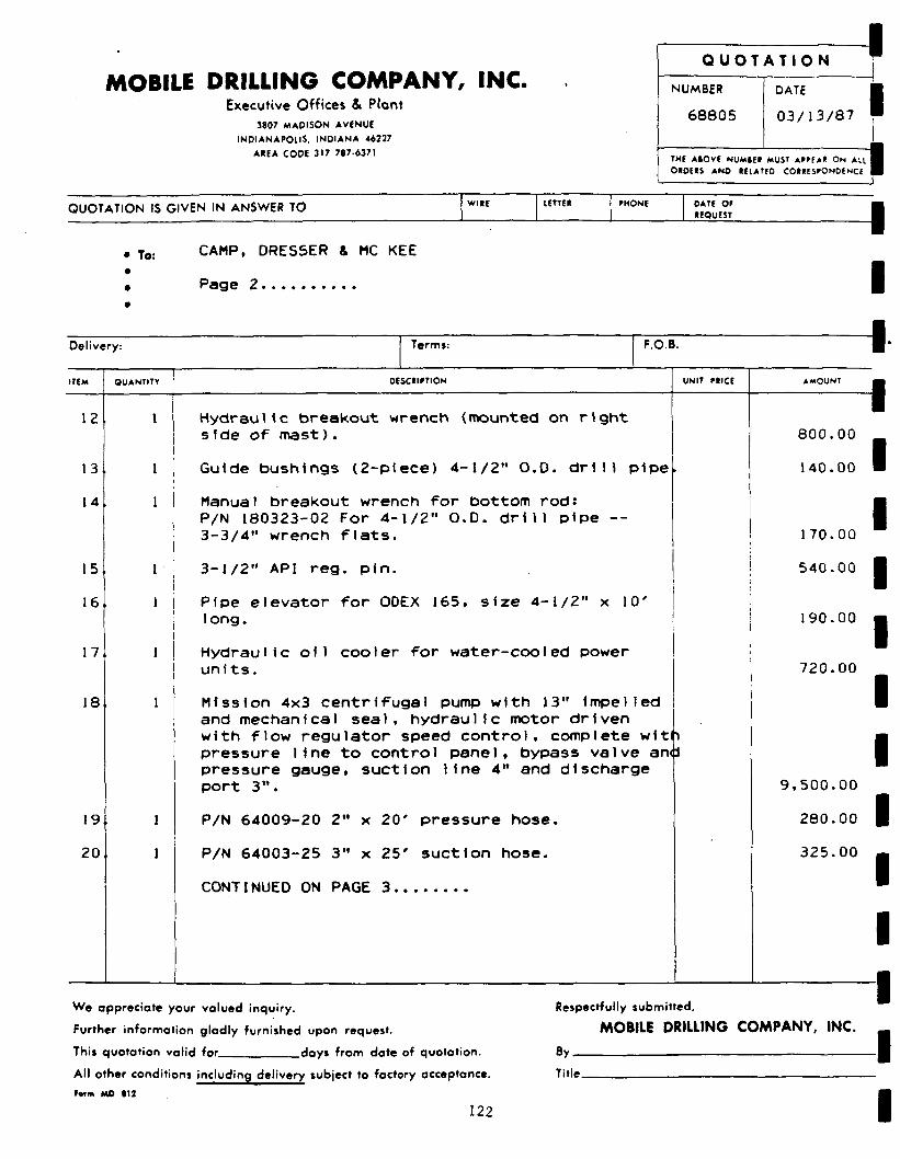
MOBILE DRILLING COMPANY, INC. Executive Offices & Plant
3807 MAPISON AVENUE
INDIANAPOLIS. INDIANA 46227
AREA CODE 317 787-6371
Q U O T A T I O N
NUMBER
68805
DATE
0 3 / 1 3 / 8 7
THE ASOVE NUMSER MUST APPEAR ON AU OIDEIS AND RELATED CORRESPONDENCE
QUOTATION IS GIVEN IN ANSWER TO WIRE PHONE DATE OP REQUEST
• To: CAMP, DRESSER & MC KEE
Page 2
Delivery: Term*: F.O.B.
ITEM QUANTITY DESCRIPTION UNIT PRICE AMOUNT
12
13
14
15
16
17
18
I I
19
20
Hydraulic breakout wrench (mounted on right s fde of mast).
Guide bushings (2-ptece) 4-1/2" O.D. drill pipe
Manual breakout wrench for bottom rod: P/N 180323-02 For 4-1/2" O.D. drill pipe --3-3/4" wrench flats.
3-1/2" API reg. pin.
Pipe elevator for ODEX 165, size 4-1/2" x 10' long.
Hydraulic oil cooler for water-cooled power units.
Mission 4x3 centrifugal pump with 13" Impelled and mechanical seal, hydraulic motor driven with flow regulator speed control, complete with pressure line to control panel, bypass valve anp pressure gauge, suction line 4" and discharge port 3".
P/N 64009-20 2" x 20' pressure hose.
P/N 64003-25 3" x 25' suction hose.
CONTINUED ON PAGE 3
800.00
140.00
170.00
540.00
190.00
720.00
9,500.00
280.00
325.00
We appreciate your valued inquiry.
Further information gladly furnished upon request.
This quotation valid for days from date of quotation.
All other conditions including delivery subject to factory acceptance.
Fetm MO 812
122
Respectfully submitted,
MOBILE DRILLING COMPANY, INC.
By
Title.
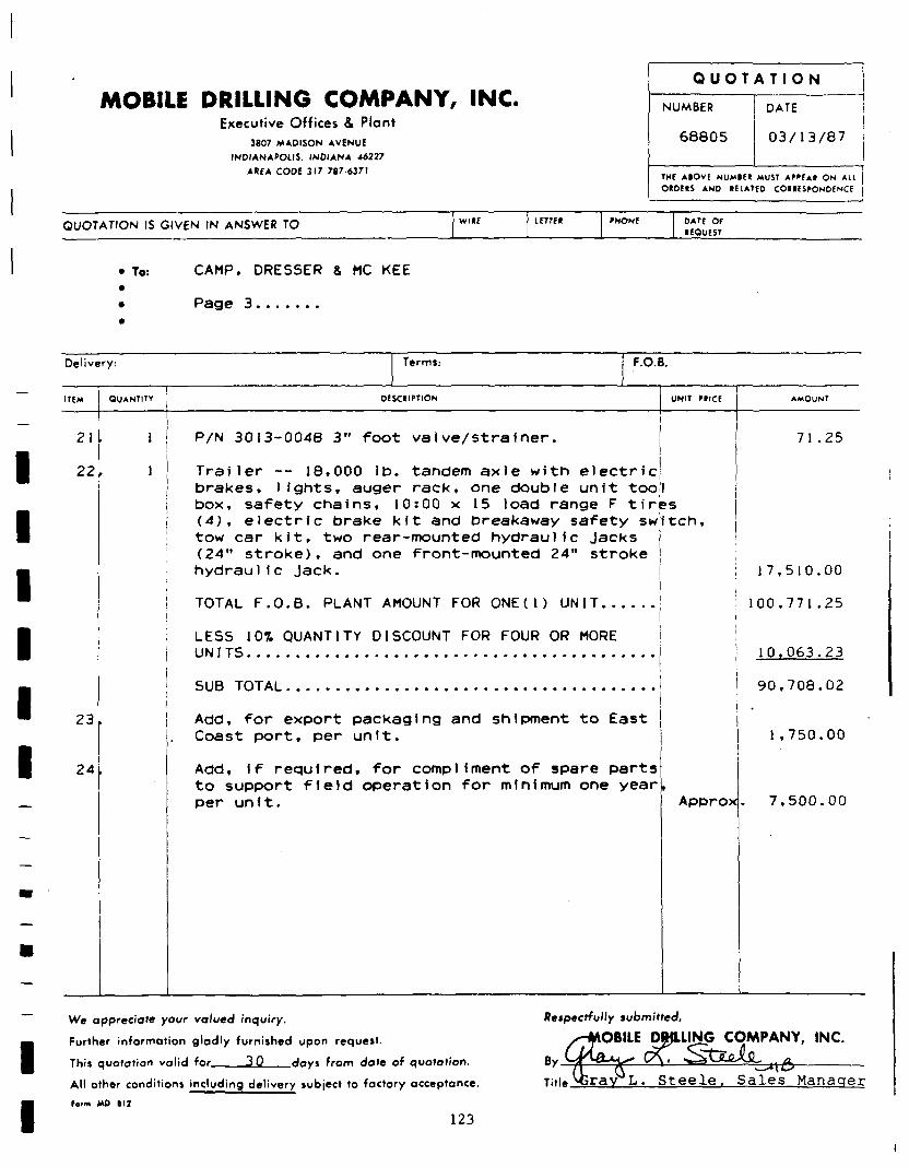
MOBILE DRILLING COMPANY, INC. Executive Offices & Plant
3807 MADISON AVENUE
INDIANAPOLIS. INDIANA 46227
AREA CODE 317 787-6371
Q U O T A T I O N
NUMBER
68805
DATE
0 3 / 1 3 / 8 7
THE ABOVE NUMBEt MUST Ar>PEAt ON All OIDEIS AND (ELATED COUESPONDENCE
QUOTATION IS GIVEN IN ANSWER TO IETTE* DATE Of • EQUEST
• To: CAMP, DRESSER & MC KEE
Page 3
Delivery: Terms: F.O.B.
ITEM QUANTITY 0ESC«IPTION UNIT MICE AMOUNT
21
22
23
24
P/N 3013-0048 3" foot vaive/strainer.
Trailer -- 18,000 lb. tandem axle with electric; brakes, lights, auger rack, one double unit too.'! box, safety chains, 10:00 x 15 load range F tires (4), electric brake kit and breakaway safety switch, tow car kit, two rear-mounted hydraulic jacks (24" stroke), and one front-mounted 24" stroke hydrauli c Jack. i
71 .25
TOTAL F.O.B. PLANT AMOUNT FOR ONE(1) UNIT.
LESS 10% QUANTITY DISCOUNT FOR FOUR OR MORE UN ITS
SUB TOTAL
Add, for export packaging and shipment to East j Coast port, per unit.
Add, if required, for compliment of spare parts to support field operation for minimum one year per unit. Approx
17,510.00
100,771.25
10,063.23
90,708.02
1,750.00
7,500.00
We appreciate your valued inquiry.
Further information gladly furnished upon request.
This quotation valid for 3_Q__days from date of quotation.
All other conditions including delivery subject to factory acceptance.
Form MO t l 2
123
Respectfully submitted,
OBILE (WILING COMPANY, INC.
By ~*xB-Titi* xSray L. S t e e l e . S a l e s Manager
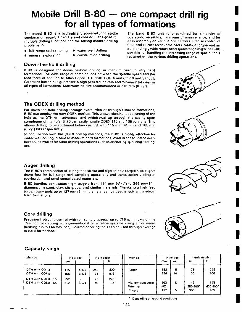
Mobile Drill B-80 — one compact drill rig for all types of formations
The model B-80 is a hydraulically powered long stroke combination auger, air rotary and core dri l l , designed for multiple dril l ing functions and for solving modern dri l l ing problems in:
• ful l-range soil sampling • water wel l dril l ing
• mineral exploration • construction dril l ing
The basic B-80 unit is streamlined for simplicity of operation, versatility, min imum of maintenance, and for easy assembly on various drill carriers. Precise control of feed and retract force (hold back), rotation torque and an outstandingly wide rotary head speed range make the B-80 suitable for handling the increasing range of special tools required in the various dril l ing operations.
Down-the-hole drilling B-80 is designed for down-the-hole dril l ing in medium hard to very hard formations. The wide range of combinations between the spindle speed and the feed force in addition to Atlas Copco DTH drills COP 4 and COP 6 and Sandvik Coromant button bits guarantee a high penetration rate and min imum bit wear in all types of formations Maximum bit size recommended is 216 mm (8 ' / 2 " ) .
The ODEX drilling method For down-the-hole dri l l ing through overburden or through fissured formations, B-80 can employ the new ODEX-method. This allows simultaneous casing of the hole as the DTH dril l advances, and wi thdrawal up through the casing upon completion of the hole B-80 can easily handle ODEX 115 and 165 versions. This allows dri l l ing to be continued below casings wi th 115 mm ( 4 ' / 2 " ) and 165 mm (6 ' / 2 " ) bits respectively.
In conjunction w i th the ODEX dri l l ing methods, the B-80 is highly effective for water wel l dri l l ing in hard to medium hard formations, even in consolidated overburden, as wel l as for other dri l l ing operations such as anchoring, grouting, testing, etc.
Auger drilling The B-80's combination of a long feed stroke and high spindle torque puts augers down fast for full range soil sampling operations and construction dri l l ing in overburden and semi-consolidated materials.
B-80 handles continuous flight augers from 114 mm ( 4 ' / 2 " ) to 356 mm(14") diameters in sand, clay, slit gravel and similar materials. Thanks to a high feed force, rotary tools up to 127 mm (5") in diameter can be used in soft and medium hard formations.
Core drilling Precision hydraulic control w i th ten spindle speeds, up to 716 rpm maximum, is ideal for rock coring wi th conventional or wirel ine systems using air or water f lushing. Up to 146 mm (5V 4 " ) diameter coring tools can be used through average to hard formations.
Capacity range
Method
DTH with COP 4 DTH with COP 6
DTH with ODEX 115 DTH with ODEX 165
Hole mm
115 165
152 212
size in
4 1/2 6 1/2
6 8 1/4
Hole depth m
250 175
75 50
ft.
820 575
245 165
Method
Auger
Hollow-stem auger Wireline Rotary
Hole size mm
152 356
203 NQ 127
in
6 14
8
5
•Hole depth m
75 30
45 200-300* 300
ft.
245 100
148 600-900*
985
* Depending on ground conditions
124
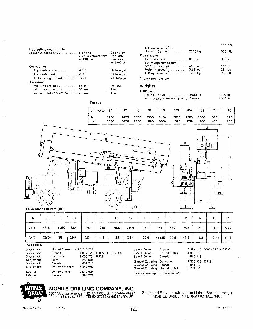
Hydraul ic pump (double sections), capacity 1.57 and
2.27 l/s respectively at 138 bar
Oil volumes Hydraul ic system 265 I
Hydraul ic tank 257 I
Lubricating oil tank 12 1
Air system
working pressure 18 bar air hose connection 50 m m extra out let connection 25 m m
Torque
21 and 3 0 I m p . gal/ min resp. at 2 0 0 0 psi
58 Imp.gal
57 Imp.gal
2.6 Imp.gal
261 psi 2 in 1 in
Li f t ing capacity ) at 0.7 m/s (28 in/s) 2 2 7 0 kg
Pipe elevator
D r u m diameter 8 9 m m
D r u m capacity (8 m m , 5 / 1 6 " wire rope) 4 6 m m Hoisting speed ) 0 .96 m/s Li f t ing capacity ) 1200 kg
) w i th empty d r u m
Weights B 8 0 basic unit
for PTO drive 3 0 0 0 kg wi th separate diesel engine 3 6 4 0 kg
5 0 0 0 lb
3.5 in
1 5 0 f t 3 8 in/s 2 6 5 0 lb
6 6 0 0 1b 8 0 0 0 lb
rpm up to 27
N m 8970
lb.ft 6620
32
7625
5620
66
3730
2750
96
2550
1880
113
2170
1600
121
2030
1500
204
1205
890
232
1060
780
425
580
425
716
340
250
Dimensions in mm (in)
A
7100
(279)
8
6600
(260)
C
1700
(68)
D
865
(34)
E
940
(37)
F
280
(11)
G
965
(38)
H
2490
(98)
I
830
(32.5)
K
370
(14.5)
L
775
(30.5)
M
790
131)
N
200
(8)
0
360
(14)
P
535
(21)
PATENTS Slidramatic Slidramatic Slidramatic Slidramatic Slidramatic Slidramatic
Lifeline Lifeline
United States US 3 .515.228 France Germany
Italy Canada United Kingdom
United Slates Canada
7.002.126 2 0 0 6 . 7 2 4
888 098 867 216
1.240.983
3.515.824 897 226
B R E V E T E S . G . D . G . D.P.B.
Safe-T-Driver Safe-T-Driver Safe-T-Driver
France United States Canada
Gimbal Coupling Germany Gimbal Coupling Canada Gimbal Coupling United States
Patents pending in other countries
7.321.113 B R E V E T E S . G . D . G . 3 .889.765
975 345
2 235 9 2 9 D P.B. 951 .130
3 .794.127
* .
MOBILE DRILLING COMPANY, INC. 3 8 0 7 M a d i s o n A v e n u e . I N D I A N A P O L I S . I N D I A N A 4 6 2 2 7
P h o n e (317 ) 7 8 7 - 6 3 7 1 T E L E X 2 7 3 5 2 or 6 8 7 6 0 1 7 ( W U I )
Sales and Service outside the United States through MOBILE DRILL INTERNATIONAL, INC.
Bfociiuie No ri'iC SM i BS 125 Pti'iCtJin1..) S A

APPENDIX L
Water Veil Education
- 127 -
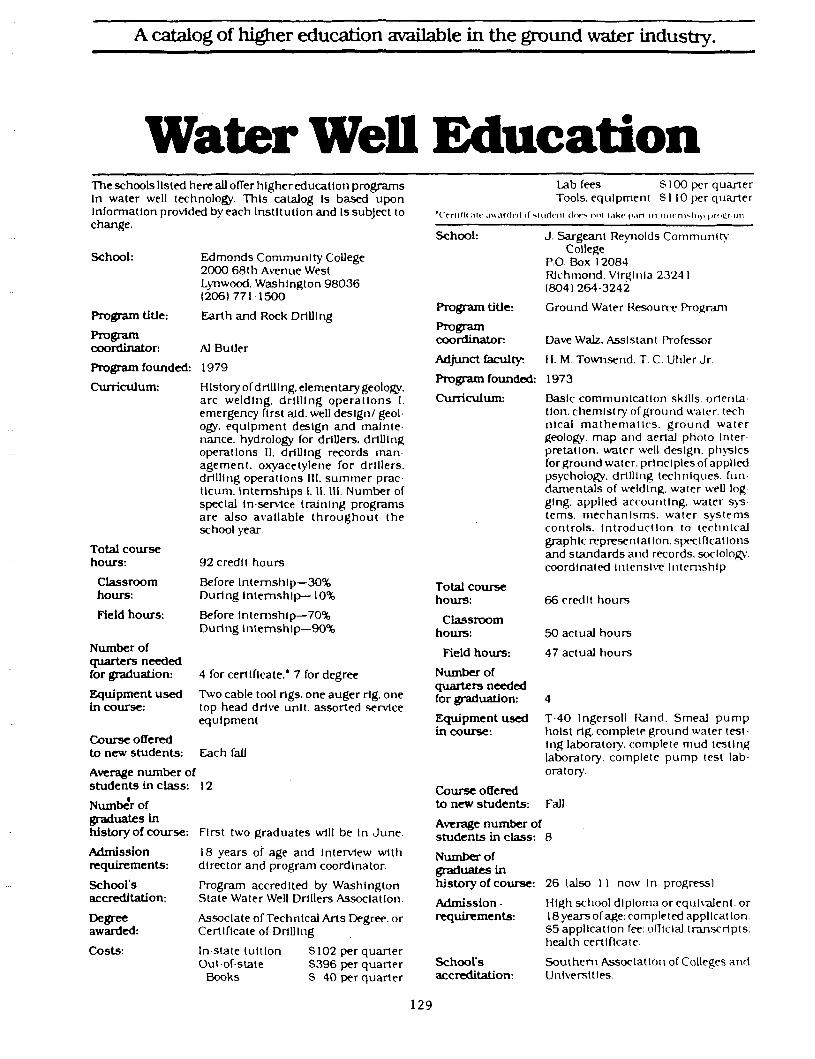
A catalog of higher education available in the ground water industry.
Water Well Education The schools listed here all offer higher education programs In water well technology. This catalog Is based upon Information provided by each Institution and Is subject to change.
School:
Program title:
Program coordinator:
Program founded:
Curriculum:
Total course hours:
Classroom hours:
Field hours:
Number of quarters needed for graduation:
Equipment used in course:
Course offered to new students:
Edmonds Community College 2000 68th Avenue West Lynwood. Washington 98036 (206)771-1500
Earth and Rock Drilling
Al Butler
1979
History of drilling, elementary geology, arc welding, drilling operat ions I. emergency first aid. well design/ geology, equipment design and maintenance, hydrology for drillers, drilling operations II. drilling records management, oxyacetylene for drillers, drilling operations III. summer prac-tlcum. Internships 1. II. 111. Number of special in-service training programs are also available th roughout the school year.
92 credit hours
Before Internship—30% During Internship—10%
Before Internship—70% During Internship—90%
4 for certificate.* 7 for degree
Two cable tool rigs, one auger rig. one top head drive unit, assorted service equipment
Each fall
Average number of students in class: 12
Number of graduates in history of course:
Admission requirements:
School's accreditation:
Degree awarded:
Costs:
First two graduates will be In June .
18 years of age and Interview with director and program coordinator.
Program accredited by Washington State Water Well Drillers Association.
Associate of Technical Arts Degree, or Certificate of Drilling
Lab fees S100 per quarter Tools, equipment SI 10 per quarter
*Ccrtill< air .luiirclrtl if siuriciit dors HIM uk r p.in in mi rn^h i j ) j irncrun
School: J. Sargeant Reynolds Community College
P.O. Box 12084 Richmond. Virginia 2324 1 (804) 264-3242
Program title: Ground Water Resource Program
Program
coordinator: Dave Walz. Assistant Professor
Adjunct faculty: H. M. Townsend. T. C. Uhler Jr.
Program founded: 1973 Curriculum: Basic communication skills, orienta
tion, chemistry of ground water, tech nlcal mathemat ics , ground water geology, map and aerial photo Inter pretatlon. water well design, physics forground water, prlnclplesof applied psychology, drilling techniques, fundamentals of welding, water well log glng, applied accounting, water systems, mechanisms, water systems controls. Introduction to technical graphic representation, specifications and standards and records, sociology, coordinated Intensive internship
66 credit hours
50 actual hours
47 actual hours
Total course hours:
Classroom hours:
Field hours:
Number of quarters needed for graduation:
Equipment used in course:
T-40 Ingersoll Rand. Smeal pump hoist rig. complete ground water testing laboratory, complete mud testing laboratory, complete pump test laboratory.
Course offered to new students: Fall
Average number of students in class: 8
In-state tuition Out-of-state
Books
S102 per quarter S396 per quarter S 40 per quarter
Number of graduates in history of course:
Admission • requirements:
School's accreditation:
26 (also 11 now In progress)
High school diploma or equivalent, or 18 years of age: completed application: S5 application fee: official transcripts: health certificate
Southern Association of Colleges and Universities
129
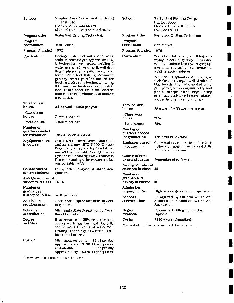
School:
Program title:
Program coordinator:
Staples Area Vocational Training Institute
Staples. Minnesota 56479 (218) 894-2430. extensions 670. 671
Water Well Drilling Technology
John Marteli
Program founded: 1973
Curriculum:
Total course hours:
Classroom hours:
Field hours:
Number of quarters needed for graduation:
Equipment used in course:
Course offered to new students:
Geology I. ground water and wells, tools. Minnesota geology, well drilling I. hydraulics, well codes, welding I. water systems I. welding II. well drilling II. planning Irrigation, water systems, cable tool fishing, advanced geology, water purification, better business, birth of a business, making It In your own business, communication. Other short units on—electric motors, dlesel mechanics, automotive mechanics.
2.100 total— 1.050 per year
2 hours per day
4 hours per day
Two 9 month sessions
One 1976 Gardner Denver 500 mud and air rig. one 1975 T-650 Chicago Pneumatic air rotary top head drive, one 43 Cyclone cable tool rig. one 35 Cyclone cable tool rig. two 20 Bucyrus Erie cable tool rigs, three water trucks, one portable welder
Fall quarter—August 31 starts new quarter.
Average number of students in class: 14-16
Number of graduates in history of course:
Admission requirements:
School's accreditation:
Degree awarded:
Costs:*
5-10 per year
Open door. If space available, student may enroll.
Minnesota State Department of Vocational Education
If at tendance Is 95% or better and course work has been satisfactorily completed, a Diploma of Water Well Drilling Technology Is awarded. Certificate to all others.
Minnesota residents $2.13 per day Approximately S130.00 per quarter Out of-state $5.33 per day Approximately $320.00 per quarter
School:
Program title:
Program coordinator:
Program founded:
Curriculum:
Total course hours:
Classroom hours:
Field hours:
Number of quarters needed for graduation:
Equipment used in course:
Course offered to new students:
Sir Sanford Fleming College P.O. Box 8000 Lindsay. Ontario K9V 5E6 (705)324 9144
Resources Drilling Technician
Ron Morgan
1976
Year One—Introductory drilling, surveying, blasting, geology, chemistry, communications, forestry, heavy equipment, car tography, mathemat ics , welding, geotechnlques.
Year Two—Exploration drilling.* gco-techrilcal drilling.* well drilling.* blasthole drilling.* advanced blasting, geohydrology. photogrammctry and photo Interpretat ion, engineering geophysics, advanced geotechnlques. Industrial engineering, engines.
28 a week for 30 weeks in a year
25%
75%
4 semesters (2 years)
Cable tool rig. rotary rig. mobile 34 H hollow stem auger. Iwo diamond drills. Air Trac compressor.
September of each year.
Average number of students in class: 35
Number of graduates in history of course:
Admission requirements:
School's accreditation:
Degree awarded:
Costs:
50
High school graduate or equivalent.
Recognized by Ontario Water Well Association. Canadian Water Well Association.
Resources Drilling Technician Diploma
$440 a year (Canadian)
*A set IMKI . idvii iucd ennrsr Is ilKrn un .ill Ihrsc s n h | n Is
*ll;is ir i lnroral .l^rct innil Willi stair of Wisconsin
130
Degree awarded:
Costs:
Certlllcaleof Ground Water Resource Program
Virginia resident
Costs: Tuition Books
Out of-state
"IVr t ri-<lii hour (XT qu.irtcr
Full time SI 14.00 Part time S 9.50* Full time $380.00 Part time $ 38.00*
School:
Program title:
Program coordinator:
Program founded:
Curriculum:
Kelsey Institute 7 ;"{ \. Box 1520 ' ' '" Saskatoon. Saskatchewan . ' ; ; / (306)664-6456 . . . .
Water Sciences Technology with a Ground Water Technology Option
JohnGll les
1969
Basic'principles of report writing. Interpersonal communications, technical' mathematics, survey theory I and II. graphics, applied physics I and II. geology. 'computers, meteorological Instrumentation, field measurements I and II. first aid. principles of management, calculus, plan reading, chemistry, hydrology 1-V. terrain analysis, hydrometrlcal Instrumentation, recreation skills, spring camp, scientific report writing, hydraulics I and II, field camp, water chemistry, s tat is t ics , operations Instrumentation, ground water geology. Instrumentation (ins ta l la t ion , main tenance : - t roubleshooting), rural domest icwalcr and wastewater systems, business management, data handl l r igand recordkeeping, water wejl. cons t ruc t ion . Instrumentation, water well maintenance and rehabilitation, oral communications, photography, water management, remote sensing, welding.
Total course hours:
Classroom hours:
Field hours:
Number of quarters needed for graduation:
Equipment used in course:
Course offered to new students :
2.400
75%">r ;
25%'
Two ycai-s'
A wide variety of surveying, water testing, flow measuring, meteorological and hydrologleal equipment.
Each fall
Average number of s tudents in class: 27
Number of graduates in history of course: 20 a year. 170 since program began.
Admission Grade 12. Including algebra and geo-requirements: trig. Preference to those who have
grade 12 chemistry and physics.
School's accreditation:
Degree awarded:
Saskatchewan Continuing Education
Water Sciences Diploma—Engineering Technology
$350 l s tS400
2nd $200
School:
Program title:
Program coordinator:
Program rounded:
Curriculum:- -
Total course hours:
Red Deer College Box 5005 Red Deer. Alberta T4N 5H5 (403)347-1788 * " '
Water Well Driller—Alberta apprenticeship training
• } ' . ' • :
Maurice Lewis ' ;.pi.
January 1979 First Period—Basic tools and skills, gasoline and dlesel engines, hydraulic and air operated equipment, welding, safety, geology, well construction and design, common drilling systems in use. other drilling systems, electrical connections. ' driver t ra ining, well pumping systems.
Second Period—Geology, well hydraulics, exploration for ground water.drll-llng systems, well pumping systems, well development, well maintenance, sanitary aspects of water well .drilling, chemical aspects of ground water, well drilling records, geologic map Interpretation.
270 hours (150 first year. 120 second year)
90%
10%
Apprenticeship: 3.600 hours
Classroom hours :
Field hours :
Number of quar ters needed for graduation:
Equipment used in course:
Course offered to new s tudents :
Total of 9 Weeks of formal education.
Most hands-on experience is through cooperating contractor. At,school students use facilities of a heavy-duty equipment shop and welding shop. Water systems accessories are used as aids.
January of each year.
Average number of s tuden t s in class: 20
Number df graduates in history of course:
Admission requirements :
School 's • accreditation:
Degree awarded:
Costs:
: 1 1 have completed apprent iceship program.
•Be at least 16 years old. Successful completion of grade 9 or equivalent. Must enter liilo a succcssfuitohtract agreement,with a contractor.
Alberta Advanced Education and Manpower. Alberta Water Well Association.
Alber ta j o u r n e y m a n well dri l ler certificate.
No tuition costs to students. Living and travel allowances paid by Canadian Manpower. If not being paid by employer, can receive unemployment compensation.
131