Embed Size (px)
Citation preview

R
1M23N31504

2
Thank you for purchasing a Futaba T-FHSS 3PV 2.4GHz system. This system is based on the combination of the newly developed 2.4GHz transmitter and its corresponding receiver. Before using your 3PV 2.4GHz system, read this manual carefully and use your R/C set safely. After reading this manual, store it in a safe place.T-FHSS 3PV 2.4GHz system• 2.4GHzSS (Spread Spectrum) radio communication system• Frequency channel setting unnecessary: Sifting the channels within the 2.4GHz band automatically, this system minimizes the
interference from other 2.4GHz systems.• Accepts no unwanted signals by using ID code• Built-in antenna (T3PV-2.4G transmitter)
Application, Export, and Modification1. This product may be used for models only. It is not intended for use in any application other than the control of models for hobby
and recreational purposes.2. Exportation precautions:(a) When this product is exported from the country of manufacture, its use is to be approved by the laws governing the country of
destination concerning devices that emit radio frequencies. If this product is then re-exported to other countries, it may be subject to restrictions on such export. Prior approval of the appropriate government authorities may be required. If you have purchased this product from an exporter outside your country, and not the authorized Futaba distributor in your country, please contact the seller immediately to determine if such export regulations have been met.
(b) Use of this product with other than models may be restricted by Export and Trade Control Regulations, and an application for export approval must be submitted.
3. Modification, adjustment, and replacement of parts: Futaba is not responsible for unauthorized modification, adjustment, and replacement of parts on this product. Any such changes may void the warranty.
Compliance Information Statement (for U.S.A.) This device, complies with part 15 of the FCC Rules. Operation is subject to the following three conditions:(1) This device may not cause harmful interference, and (2) This device must accept any interference received, including interference that may cause undesired operation. (3) RF Exposure Information (SAR)This device meets the government's requirements for exposure to radio waves. This device is designed and manufactured not to exceed the emission limits for exposure to radio frequency (RF) energy set by the Federal Communications Commission of the U.S. Govern-ment. The exposure standard employs a unit of measurement known as the Specific Absorption Rate, or SAR. The SAR limit set by the FCC is 1.6 W/kg. Tests for SAR are conducted using standard operating positions accepted by the FCC with the EUT transmitting at the specified power level in different channels.
The FCC has granted an Equipment Authorization for this device with all reported SAR levels evaluated as in compliance with the FCC RF exposure guidelines. SAR information on this device is on file with the FCC and can be found under the Display Grant section of www.fcc.gov/eot/ea/fccid after searching on FCC ID: AZPT3PV-24GThe responsible party for the compliance of this device is:Futaba Service Center3002 N Apollo Drive Suite 1, Champaign, IL 61822 U.S.ATEL (217)398-8970 or E-mail: [email protected] (Support) TEL (217)398-0007 or E-mail: [email protected] (Service)
Battery Recycling (for U.S.A.)The RBRCTM SEAL on the (easily removable) nickel-cadmium battery contained in Futaba products indicates that Futaba Corporation is voluntarily participating in an industry program to collect and recycle these batteries at the end of their useful lives, when taken out of service within the United States. The RBRCTM program provides a convenient alternative to placing used nickel-cadmium batteries into the trash or municipal waste system, which is illegal in some areas. You may contact your local recycling center for information on where to return the spent battery. Please call
1-800-8-BATTERY for information on NiCd battery recycling in your area. Futaba Corporation involvement in this program is part of its commitment to protecting our environment and conserving natural resources.
RBRCTM is a trademark of the Rechargeable Battery Recycling Corporation.Federal Communications Commission Interference Statement (for U.S.A.)This equipment has been tested and found to comply with the limits for a Class B digital device, pursuant to Part 15 of the FCC Rules. These limits are designed to provide reasonable protection against harmful interference in a residential installation.This equipment generates, uses and can radiate radio frequency energy and, if not installed and used in accordance with the instructions, may cause harmful interference to radio communications. However, there is no guarantee that interference will not occur in a particular installation. If this equipment does cause harmful interference to radio or television reception, which can be determined by turning the equipment off and on, the user is encouraged to try to correct the interference by one or more of the following measures: --Reorient or relocate the receiving antenna. --Increase the separation between the equipment and receiver. --Connect the equipment into an outlet on a circuit different from that to which the receiver is connected. --Consult the dealer or an experienced radio/TV technician for help.
CAUTION:To assure continued FCC compliance: Any changes or modifications not expressly approved by the grantee of this device could void the user's authority to operate the equipment.
WARNING: This product contains a chemical known to cause cancer and birth defects (or other reproductive harm).

3
Safety Precautions ............................................. 4Definition of Symbols ...................................................................... 42.4GHz System Precautions ............................................................ 4Operation Precautions .................................................................... 4Storage and Disposal Safety Precautions ...................................... 6Other Safety Precautions ................................................................ 6
Before Operation ................................................ 7System Contents .............................................................................. 7Telemetry System ............................................................................ 7Nomenclature / Handling ............................................................... 8Battery Replacement Method ........................................................ 9When Using The Optional Battery ............................................... 10Key Operation ............................................................................... 11
Assembly / Adjustment ..................................... 12Receiver and Servo Connection .................................................... 12Receiver Antenna Installation ..................................................... 12Assembly Precautions ................................................................... 13How to Link .................................................................................... 14Transmitter Set-Up Procedures ..................................................... 15
3PV-2.4G Functions .......................................... 16Model Selection/Model Reset (MDL) ............................................ 16Model Name (MDL NAME) ............................................................ 16Low Battery Alarm (LBA) .............................................................. 16System Type (SYS) .......................................................................... 16Link Mode (Only T-FHSS) ............................................................... 17DT3 Seletion (DT3) ......................................................................... 17SW1 ................................................................................................. 17Steering Trim (TRM-CH1) .............................................................. 17Throttle Trim (TRM-CH2) ............................................................... 18Channel-4 Trim (TRM-CH4) ........................................................... 18SUB Trim (CH1-CH4) ..................................................................... 18Steering Dual Rates (D/R) ............................................................. 18Steering End Point Adjustment (EPA-CH1) ................................. 19Throttle End Point Adjustment (EPA-CH2) ................................. 19Channel-3 End Point Adjustment (EPA-CH3) .............................. 19Channel-4 End Point Adjustment (EPA-CH4) .............................. 194WS/BRK Mixing (SMX) ................................................................. 20Steering Servo Reversing (REV-CH1) ........................................... 20Throttle Servo Reversing (REV-CH2) ............................................ 20Channel-3 Servo Reversing (REV-CH3) ........................................ 20Channel-4 Servo Reversing (REV-CH4) ........................................ 21Steering EXP (EXP-CH1) ................................................................ 21Throttle EXP (EXP-CH2) ................................................................. 21Throttle Fail Safe Function ........................................................... 22ABS function .................................................................................. 22Model Data Copy (COPY) ............................................................... 22
Reference .......................................................... 23Ratings ............................................................................................ 23When Requesting Repair .............................................................. 23
Table of Contents

4
Operation Precautions WARNING
When using a rechargeable battery to power your system, always charge and check the battery voltage prior to operation. Should the battery discharge below the minimum voltage level, control will be lost.
Prior to operation always perform a range test. Even one abnormality in the R/C system may cause loss of control.
Safety Precautions
2.4GHz System PrecautionsWARNING
Do not cover/hold the built-in antenna part of T3PV-2.4G transmitter by your hand during running. Do not put any conductive plate/sticker on the antenna part.Otherwise, the operating range may become shorter.
Do not perform the linking procedure when motor's main wire is connected or the engine is operating as it may result in serious injury.
While the linking is done, please cycle receiver power and check if the receiver to be linked is re-ally under the control of the transmitter to be linked.
Always use receiver rechargeable battery or regulated output from your ESC. Using dry cell batteries may cause malfunction.Be sure that when using an ESC's regulated output, the capacity of the ESC meets your usage condition.
In order to maintain complete control of your car/boat it is important that it remains visible at all times. Running behind large objects is not suggested. Doing so may result in the reduction of the quality of the radio frequency link to the model.
For your safety as well as that of others, please read this manual thoroughly prior to installation and operation of your digital proportional R/C system.
Definition of SymbolsThe following defines the symbols used in this manual.
Explanation of Symbols
DANGER Procedures which may lead to a dangerous condition and cause death or serious injury to the user if not carried out properly.
WARNINGProcedures which may lead to a dangerous condition or cause death or serious injury to the user if not carried out properly, or procedures where the probability of superficial injury or physical damage is high.
CAUTION Procedures where the possibility of serious injury to the user is small, but there is a danger of injury, or physical damage, if not carried out properly.
Explanation of Graphic SymbolsIndicates an operation that prompts a warning (including Caution).
Indicates an operation that must not be performed.
Indicates an operation that always must be performed.

5
[Range Test Procedure]Have a friend hold the model, or place it on a stand where the wheels or prop cannot come in contact with any object. Operate from a distance of about 100 feet. Be sure to check the move-ment of each servo to make sure it follows the movement of the steering wheel and throttle trig-ger. If the servos do not follow the commands from the transmitter or any type of interference is detected, Do Not operate the model.
Never operate in the rain or run through puddles. The transmitter, receiver, batteries and most servos and speed controls are not waterproof. Con-tact with any type of moisture or immersion in water or snow will cause damage along with pos-sible loss of control. Should any type of moisture enter any component of the system, immediately stop using the R/C system and return it to our service center for inspection.
Do not operate when visibility is limited. Should you lose sight of the model, a collision or other dangerous situation may occur.
Do not operate near people or roads. Do not operate on any pond when boats are present.Do not operate near high tension power lines or communication broadcasting antennas.Prior to the operation of any model, be sure the area you plan to use is safe. Be aware of all ob-jects that may be in the path of your model. Do not operate the model where people or any type of moveable object could stray in the path of your model. Control loss due to interference, compo-nent failure, loss of sight or low battery voltage could result in serious injury to yourself and others as well as damage to your model.
Do not operate when you are tired, not feeling well or under the influence of alcohol or drugs. Your judgment is impaired and could result in a dangerous situation that may cause serious injury to yourself and others.
(Turning on the power switches)Always check the throttle trigger on the transmitter to be sure it is at the neutral position.1. Turn on the transmitter power switch.2. Turn on the receiver or speed control power switch.
(Turning off the power switches)Always be sure the engine is not running or the motor is stopped.1. Turn off the receiver or speed control power switch.2. Then turn off the transmitter power switch.
If the power switches are turned off in the opposite order the model may unexpectedly run out of control and cause a very dangerous situation.
Make all adjustments to the radio control system with the engine not running, or the electric motor disconnected. If the engine is running or the motor is connected while adjustments are made, the model may run out of control.
Remove the main battery source from electric powered models when they are not being used.Should you accidentally leave the receiver switch on, the model could run out of control.
(Fail safe function)Before running (cruising), check the fail safe function.
Check Method:Before starting the engine, check the fail safe function as follows:1. Turn on the transmitter and receiver power switches.2. Turn off the transmitter power switch.3. Check if the fail safe function moves the servos to the preset position when reception fails.The fail safe function is a safety feature that minimizes set damage by moving the servos to a preset position when reception fails. However, if set to a dangerous position, it has the opposite effect.Setting example: Throttle idle or brake position
Do not touch the engine, motor, speed control or any part of the model that will generate heat while running.Touching hot parts will result in serious burns.
CAUTION
When the charger is not in use, disconnect it from the outlet. This will prevent accidents, overheat-ing and short circuits.

6
Storage and Disposal Safety Precautions WARNING
At the end of a day's operation, store the system with NiCd battery discharged. Be sure to recharge the system before it is used again.You should fully discharge your system's batteries periodically to prevent a condition called "mem-ory". For example, if you only make two runs in a day or you regularly use a small amount of a battery's capacity, the memory effect can reduce the actual capacity even if the battery is charged for the recommended amount of time.
Do not throw a battery into a fire. Do not disassemble or attempt to repair a battery pack. Overheating, damage and acid leakage may lead to burns, loss of eyesight as well as numerous other types of injuries. The electrolyte in batteries is a strong alkali. Should you get even the small-est amount of the electrolyte in your eyes, Do Not rub. Wash immediately with water, and seek medical attention at once. The electrolyte can cause blindness. If electrolyte comes in contact with your skin or clothes, wash with water immediately.
Do not leave the radio system or models within the reach of small children.A small child may accidentally operate the system. This could cause a dangerous situation and injuries. Batteries can be very dangerous when mishandled and cause chemical damage.
CAUTION
Do not store your R/C system where it will be exposed to the following conditions.• Extreme heat or coldness • Direct sunlight• Where humidity is high• Where vibration is prevalent• Where dust is prevalent• Where there is steam and condensationStoring your R/C system under adverse conditions could cause deformation and numerous other problems with operation.
If the system will not be used for a long period of time, remove the batteries from the model and store in a cool, dry place.If the batteries are left in the model, electrolyte may leak and damage the model.
<Battery Recycling>A used battery is valuable resource. Insulate the battery terminals and dispose of the battery by taking it to a battery recycling center.
Other Safety Precautions CAUTION
When operating two or more models at the same time, have a third person act as a spotter. They will be in charge of safety and you should follow their instructions.
Beginners should receive instructions regarding safety and operation from an experienced modeler.
Always use only genuine Futaba transmitters, receivers, servos, and electronic speed controls, along with other optional parts and components. Futaba will not be held responsible for damages caused by other than genuine Futaba parts and components. Use only genuine Futaba parts and components listed in the instruction manual and catalog.
Do not short circuit the battery terminals. Short circuiting the terminals will lead to sparks and overheating and could cause a fire and burns as well.
Do not expose plastic parts to fuel, motor spray, waste oil or exhaust.The fuel, motor spray, waste oil and exhaust will penetrate and damage the plastic.
<Battery Electrolyte>The electrolyte in batteries is a strong alkali. Should you get even the smallest amount of the electrolyte in your eyes, DO NOT RUB. Wash immediately with water and seek medical attention at once. The electrolyte can cause blindness. If electrolyte comes in contact with your skin or clothes, wash with water immediately.

7
Before Operation
After opening the container, check the contents for the following items. The contents will vary with the system purchased.
3PV-2.4GHz System Contents
Transmitter T3PV-2.4G (x1)System T-FHSS/S-FHSS/FHSS
Receiver R203GF or R304SB or R314SB (x1)System S-FHSS/FHSS T-FHSS T-FHSS
Miscellaneous Mini Screwdriver
NOTE: This Futaba T-FHSS/S-FHSS/FHSS system, including the T3PV-2.4G transmitter, does not work with current Futaba FASST™ systems. Futaba FASST™ systems and T-FHSS/S-FHSS/FHSS system are not compatible.
Receiver R203GF Receiver R314SB(R304SB)
Connectors "3" : Channel-3 Servo (CH3)"2" : Throttle Servo (CH2)"1" : Steering Servo (CH1) "B": Power connector
Connectors "4" : Channel-4 Servo (CH4)"3" : Channel-3 Servo (CH3)"2" : Throttle Servo (CH2)"1" : Steering Servo (CH1) "S.BUS2": SBS-01V/S.BUS2 equipment
Link Switch LED Link SwitchLED
System Contents
Telemetry System
3-Channel S-FHSS/FHSS auto detection system
4-Channel T-FHSS system
*4WS/BRK Mixing (SMX) can't be used in R203GF.
The voltage of the receiver is shown to a transmitter.
*Telemetry can't be used in R203GF.
R314SB/R304SB is T-FHSS, telemetry system can use it.R203GF is S-FHSS/FHSS, telemetry system can't be used.
■ Default Telemetry System
Receiver voltage display
■ SBS-01V (Voltage sensor ; Option) can be used.
Connect SBS-01V to S.BUS2 port of a receiver.Wiring connection a EXT line of SBS-01V to the battery.
*Indication only of the EXT voltage of the SBS-01V.*When connecting SBS-01V, the receiver battery voltage isn't indicated.*When indicating the EXT voltage, wiring connection work is needed. Please refer to a manual of SBS-01V.*The start slot number of the SBS-01V has to be "6" of a default.*T3PV can't use other telemetry sensors.
Receiver battery voltage
SBS-01V→ EXT battery voltage
The receiver power supply can be con-nected to the S.BUS2 port or any of CH1-4.
HOME Screen

8
WARNING
Do not cover/hold the built-in antenna part of T3PV-2.4G transmitter by your hand during running. Do not put any conductive plate/sticker on the antenna part.Otherwise, the operating range may become shorter.
Antenna (Built-in)
LCD screenPower switch turned on: Beep confirm-ation sound is generated and the model name is displayed for about two seconds and then the initial screen appears.
Steering Trim Lever (DT1)
Steering Wheel
Throttle Trigger
Grip Handle
Battery cover
Power Switch
Throttle Trim Lever (DT2)
Press for about 1 second→ONPress for about 1 second→OFF
Adjusts the steering in small increments so the model will run straight.
Turn model to left or right.
Channel 3 SwitchTurn channel 3 servo to left or right.
Select KeyPress the Select key to select the desired function screen.
LEDON→ SolidLow battery→ Blinks
+- KeyIt is used to change a setup.Press the +key and -key sim-ultaneously for about 1 second → Value is reset.
Steering D/R Lever (D/R)
Adjusts the throttle in small increments so the model will not move at neutral.
Adjust the vehicle's steering sensitivity across the entire range.
Digital trim DT1, DT2, and D/R operation Push the lever to the left or right (up or down). The current position is displayed on the LCD screen for about two seconds. Each step is indicated by a tone. When the trim exceeds the maximum trim adjustment range, the beep tone will change and the servo will not move any further. Remember, the trims are digital so the position of each trim is remembered for each model separately.
Control the speed of the model and movement forward and backward.
(Initial screen)• Model memory number display• Battery voltage display
(*1)
(*1)
(*1)
(*1)
The antenna is inside of this part.
WARNING
Nomenclature/HandlingTransmitter T3PV-2.4G
As with al l radio frequency transmissions, the strongest area of signal transmission i s f r o m t h e s i d e s o f t h e antenna(bui l t - in). As such, the antenna (arrow direction) should not be pointed directly at the model.

9
Battery Replacement Method
Battery cover
CAUTION Always be sure you reinsert the batteries in the
correct polarity order. If the batteries are loaded incorrectly, the transmitter may be damaged.
When the transmitter will not be used for any short or long period of time, always remove the batteries. If the batteries do happen to leak, clean the battery case and contacts thoroughly. Make sure the contacts are free of corrosion.
4 AA size batteries
If the transmitter battery voltage drops below 4.2V an alarm will sound.
Low Battery Alarm:
BlinksTransmitter battery voltage
The low battery alarm is meant to be a safety feature only. Do NOT operate your radio below 4.5V. Always shut your radio off as soon as possible after the low battery warning tone to avoid loss of control.
Check:Turn the power switch on the transmitter to the ON position. Check the battery voltage display on the LCD screen.If the voltage is low, check the batteries for insufficient contact in the case or incorrect battery polarity.
Attention!+- Direction
Load the new AA size batteries. Pay very close attention to the polarity markings and reinsert accordingly.
Slide the battery cover back onto the case.
Remove the battery cover from the transmitter by sliding it in the direction of the arrow in the figure.

10
CAUTIONNever try to recharge a dry cell battery.■ The transmitter may be damaged or the bat-
tery electrolyte may leak or the battery may break.
Insert the batteries in the correct polarity.■ If the polarity is incorrect, the transmitter may
be damaged.When the transmitter is not in use, remove the batteries.■ If the battery electrolyte leaks, wipe off the
case and contacts.
CAUTIONDo not use commercial AA size NiCd and NiMH batteries.■ Quick charging may cause the battery contacts
to overheat and damage the battery holder.When closing the battery cover, be careful that the battery cover does not pinch the bat-tery lead wires.■ Shorting of the battery lead wires may lead to
fire and abnormal heating and cause burns or fire disaster.
When using an optional rechargeable battery, replace the battery as described below.-The type of power source used must be set by system setting.-When the transmitter will not be used for a long time, remove the battery.
Optional battery
NiMH : HT5F1800B
Charge Jack of T3PV is used
After removing the dry cell battery box from the transmitter, disconnect the connector.Insert the connector of the new battery and load the new battery into the transmitter.
Connect the battery connector
When charging it, LiFe battery is removed from transmitter.
Balance charging connector for LiFe battery charger.
LiFe : FT2F1700BV2/FT2F2100BV2
Charge the optional FT2F1700BV2/2100BV2 (LiFe) battery with the special charger in accordance with the instruction manual supplied.When the battery will not be used for a long time, to prevent it from deteriorating we recommend that it be kept in about the half capacity state instead of fully charged. Also be careful that the battery does not enter the over-discharged state due to self-discharge. Periodically (about every 3 months) charge the battery.
When Using The Optional Battery

11
Key Operation
Model Select
Model Nam
e
Low Battery Alarm
System Type
Link Mode
(Only T-FHSS
)
DT3 Selection
SW1
Trim CH1
End Point CH4
(at Special MIX
)
Trim CH2
Trim CH4
(at Special MIX
)
End Point CH1
Sub Trim CH3
End Point CH3
Dual Rate
Sub Trim CH2
End Point CH2
Sub Trim CH4
(at Special MIX
)
Sub Trim CH1
Special Mixing
Reverse CH1
Reverse CH2
Reverse CH3
Reverse CH4
(at Special MIX
)
Exponential CH1
Exponential CH2
Battery Fail Safe
(Only T-FHSS
)
Fail Safe
ABS
Model Copy
HOME
+Setup Value UP
-Setup Value DOWN
Press → Function Menu Press → Function Menu
Press → Function is selected Press → Function is selected
Press and hold → HOME screen Press and hold → HOME screen
HOME ScreenPower ON
The model name is displayed (2 second)
Press Press and hold
Power SwitchPress and hold → ON/OFF
T-FHSS (R304SB/R314SB)→Receiver voltage displayS-FHSS/FHSS (R203GF)→ Not display
Press
Press
Return to the value by pressing the (+ ) and (- ) keys simultaneously for about 1 second.
This function will switch off the transmitter if you forget. When the steering and throttle switch are not operated for 10 minutes, power automatically turns off.
Auto Power OFF

12
Assembly / Adjustment
As you connect the receiver, servos and other components, do so in accordance with the "Assembly Precautions".
Install the R203GF/R304SB/R314SB receiver on the car as follows:
Note: The operating range may become shorter, depending on where the receiver and the antenna are mounted.
WARNING
Install the antenna in the higher place as shown in the figure.Keep the antenna as far away from the motor, ESC and other noise sources as possible.Put the antenna in the antenna tube to protect it.
Do not cut the antenna.Do not bend the coaxial cable. Doing so causes damage.
Antennatube
Antenna
Coaxialcable
Receiver
Receiver and Servo Connection
Receiver Antenna Installation
B/C
CH3
CH2
CH1
CH4
Receiver
SwitchTo Battery
CH4 servo
CH3 servo
Throttle servo
Steering servo
Installation When An Electronic Speed Control Is Used
Installation For Gas Powered Models
e.g. R314SB
e.g. R314SB

13
WARNING
Check the receiver, servos, and battery connectors, to be sure they are firmly connected. If a connector is not fully inserted, vibration may cause the connector to work loose while the model is operating. This will result in loss of control.
Operate each servo horn over its full stroke and check to see that the linkage does not bind or is not too loose. Excessive force applied to the servo horn by binding or poor installation may lead to servo problems and result in loss of control.
(Electric Cars and Boats)Isolate the receiver from vibration by attaching to the chassis or mounting plate with thick double sided tape.
(Gas Powered Cars and Boats)Isolate the receiver from vibration by wrapping it in foam rubber or similar type cushioning material. Protect the unit from water damage by placing it in a plastic bag or waterproof radio box. The receiver contains precision electronic parts. These parts are vulnerable to vi-bration and shock. Any contact with moisture (water or condensation) may cause receiver malfunction and loss of control.
Keep all devices that emit high frequency noise, such as motors, batteries, and wiring that handles heavy current loads, at least 1/2 inch away from the receiver and the receiver antenna.High frequency noise will cause a decrease in operating range and could cause loss of control.
Install electronic speed control heat sinks as well as other components that conduct electricity so they cannot come in contact with aluminum, carbon fiber or other materials that conduct electricity. If, for example, the speed control came loose while the model was running and touched an aluminum chassis, a short circuit may occur that would cause irrepa-rable damage to the system as well as loss of control.
Noise suppression capacitors should be installed on almost all motors. If the proper capacitors are not installed, high frequency noise will reduce range and cause loss of control along with various other problems.
Inspect all linkage installations and any point where metal could come in contact with other metal parts. Make sure these parts do not touch other metal parts under vibration.Should a linkage or other metal parts come in contact with other metal parts under vibration, the high frequency noise generated by this contact will cause interference and possible loss of control.
CAUTION
Do Not disassemble any part of this system that is not specified in the instruction manual. Futaba will not be responsible for any damage due to improper disassembly of any part of the radio control system.
Assembly Precautions

14
Each transmitter has an individually assigned, unique ID code. In order to start operation, the receiver must be linked with the ID code of the transmitter with which it is being paired. Once the link is made, the ID code is stored in the receiver (T-FHSS; and transmitter) and no further linking is necessary unless the receiver needs to be used with another transmitter. (For T/R set, the link is already done at factory.)
Link procedure S-FHSS/FHSS (R203GF)
1 Bring the transmitter and the receiver close to each other, within 20 inches (half meter).
2 Turn on the transmitter and the receiver.
3 Push and hold the Link Switch of the receiver.
4 When the link is complete, the LED in the receiver changes to solid green.
*Please refer to the table below for LED status vs receiver's condition.
LED status vs receiver's condition:No signal reception LED : OFF
Receiving signals LED: Green ON
Receiving signals, but ID is unmatched LED: Green Blink
Link procedure T-FHSS (R304SB/R314SB)
1 Bring the transmitter and the receiver close to each other, within 20 inches (half meter).
2 Turn on the transmitter.
3 Select [LINK] and access the setup screen shown below by pressing the select key [▶]. Next, press and hold [ + ] or [ - ] key.
4 Turn on the receiver.
5 During countdown, push and hold the receiver tact switch. The LED will begin to blink red. After the receiver LED switches from blinking red and green → red steady light, release the tact switch of the receiver. If the receiver LED lights green, linking was successful. Also check servo operation.*Please refer to the table below for LED status vs receiver's condition.
LED status vs receiver's condition:No signal reception Red : On
Receiving signals Green: On
Unrecoverable failure (EEPROM,etc.) LED: Red and Green turn on alternately
Link Switch LED
How to Link
■Link Mode Press and hold +or -key.Link mode for 20 seconds.Blink with Link mode
+ or - Press and hold
Link SwitchLED
*Link is required when a new model is made from a model selection.

15
*When making these setting adjustments, do so with the motor disconnected or the engine not running.
NEUTRAL, HIGH, AND BRAKE MAX POINTS SETTINGS
Before setting each point, set the transmitter throttle channel trim to neutral.Turn on the power in transmitter -> amp order.1
2Transmitter throttle operation
・Neutral state・Press the pushbutton switch.
(0.5 secs or longer)(Confirmation beep sounds)
・Continuous single blink
MC231CR /MC331CR(Pushbutton switch operation) (Checker LED)
N
NFull High
Full brakeN
Neutral point setting
3
・Full high state・Press the pushbutton switch.
(Confirmation beep sounds)
・Continuous double blinkHigh point setting
4・Full brake state ・Press the pushbutton switch.
(Confirmation beep sounds.)・If the LED goes out,
setting is complete.
Brake MAX point setting
Set the throttle adjustment function (EPA) to 100% and the ABS function to OFF using the transmitter throttle channel function.If the throttle angle is too large or the ABS functions are on, erroneous operation may occur.
*When using the ABS function, after setting up the MC231CR / MC331CR, stop the reverse function, then turn on the ABS function. If the ABS function is on, the MC231CR / MC331CR cannot be set up correctly.
(Preparations)Select the model memory that is not used and reset it to the initial values with the model selection and model reset functions.
Servo Horn Installation Instructions
1 Connect the receiver, servos, and other components and then turn on the power switches to the transmitter and receiver.
*Both servos will move to the neutral position.
2 At this time install the servo horn in the manner described in the instruction manual provided with the model this system will be used in.
Reversing The Servo Operation Direction Should the servo operate in the opposite direction required for your application, reverse the direction with the servo reversing.
E.S.C. MC231CR / MC331CR
Transmitter Set-Up Procedures
Model number(1 - 0)
Model name
Model ResetPush the DT1 lever right or left for about two seconds. All data stored in the currently selected model memory is erased.
Model Selection
Selection key
Throttle Servo Reverse
NOR: NormalREV: Reverse Direction change
NOR: NormalREV: Reverse
Steering Servo Reverse
Direction change

16
3PV-2.4G FunctionsModel Selection / Model Reset(MDL)
Low Battery Alarm(LBA)
System Type(SYS)
The model selection selects the desired model memory from the 10 model memories stored within the transmitter, and the model reset erases all data stored in a specific model memory.
Model Name(MDL NAME)
Model number(1 - 0)
Model name
Model ResetPush the DT1 lever right or left for about two seconds. All data stored in the currently selected model memory is erased.
Model Selection
Selection key
T h i s f u n c t i o n p r o v i d e s a 4-character name for each of the model memories in the transmitter to easily select the correct setup for the model currently in use.• Clearly label each model for easy
selection.
Select the battery alarm voltage according to the battery to be used.*The voltage drop of a rechargeable battery
and a dry cell battery is different. When using a rechargeable battery, always change the voltage.
System changes (T-FHSS, S-FHSS, FHSS, T-FHSS <High-Speed>) matched to the receiver type.
●4 dry cell batteries ⇒ 4.2V ●HT5F1800B (5cell NiMH battery) ⇒ 5.0V ●FT2F1700BV2/FT2F2100BV2 (2cell LiFe battery) ⇒ 5.8V
Model Name
(Selection)
Model number(1 - 0)
Model name
(Selection key)
Low battery voltage
Alarm start voltage
Voltage change
System Type
TFH: T-FHSSSFH: S-FHSSFH: FHSSTFH-HS: T-FHSS <High-Speed>
System change
●R314SB/R304SB- T-FHSS (TFH), T-FHSS High-Speed (TFH-HS) : The voltage of the receiver is shown to a transmitter.●R203GF--- S-FHSS (SFH), FHSS (FH)
When using the T3PV in the T-FHSS High-Speed mode, always use it under the following conditions:Servos :Futaba digital servo (including BLS Series brushless servos) Receiver’s battery :Matched to the ratings of the receiver and connected digital servo (dry cell battery can-not be used).
Under other conditions, the set will not operate, or the specified performance will not be displayed even if it operates. In addition, it may cause servo trouble.
Power Switch: OFF → ON
When the system was changed and when a model of a different system was selected, signal are output in the system set at the point at which the transmitter power was turned back on.

17
*Link is required when a new model is made from a model selection.
*When telemetry can't be used, try a relink once again.
Link Mode(Only T-FHSS)This function is in case of T-FHSS. When linking, it's necessary to place the transmitter in link mode.
■Link Mode Press and hold +or -key.Link mode for 20 seconds.Blink with Link mode
+ or - Press and hold
D/R:Dual rate(CH1)CH3:3 channel move
DT3 function
Function change
DT3 Selection(DT3)
SW1
The function of DT3 is chosen.D/R (dual rate) or CH3.
The function of SW1 is chosen.CH3 or OFF. CH3:SW1→3 channel move
OFF:SW1→OFF
SW1 function
Function change
DT3
SW1
Racers Tip When you install a servo, always check to be sure the servo is at its neutral position. Adjust the servo horn hole position and linkage so both are parallel. When a servo saver is used, place it as close to center position as possible. Be sure the steering trim on the transmitter is at the neutral position.
Trim Operation And Maximum Travel With the center trim feature, trim adjustments have no effect on the maximum servo travel. This prevents the linkages from binding when adjustments are made.
When Trim usage is extreme If it takes most of your trim movement to get a servo to the neutral position, reposition the servo horn or servo saver on the servo and inspect your linkage installation.
Steering Trim(TRM-CH1)Steering neutral adjustments can be made by moving the Steering trim knob to the left or right.
90°
90°
Parallel
Servo Saver
Direct Servo Saver Horn
(L100~0~R100)
Steering Trim
or
+ and - Press and hold
Trim change
Reset
Trim change
Press Trim Reset

18
Throttle Trim(TRM-CH2)
SUB Trim(CH1-CH4)Use this function to adjust the neutral position of the steering, throttle and channel 3 (4) servos.Subtrim shifts the entire servo travel range in the set direction.
Throttle neutral adjustments can be made moving the throttle trim up or down.
Racers Tip When using an electronic speed control, set the throttle trim to neutral and make adjustments to the speed control. On a gas powered model, set the trim to neutral and adjust the linkage to the point where the carburetor is fully closed in accordance with the engine instruction manual.
Trim Operation and Maximun Travel With the center trim feature, trim adjustments have no effect on the maximum servo travel. This prevents the linkages from binding when adjustments are made.
When trim movement is extreme If you use most of the trim movement to get the servo to the neutral position, recenter the servo horn closer to the neutral position and inspect your throttle linkage.
Throttle Trim
or
+ and - Press and hold
Trim change
Reset
Trim change(F100~0~B100)
Press Trim Reset
(Drum Type)
(Slide Type)
Carburetor Fully Closed
Channel-4 Trim(TRM-CH4)
*It can't be used in R203GF.
*CH4 can't be used in R203GF.
At 4WS mixing function:The neutral adjustments of the rear steering servo can be made by pressing the +/- key.
At brake mixing function:The neutral adjustments of the front brake servo can be made by pressing the +/- key.
(This setting screen is displayed when 4WS mixing or Brake mixing is activated.)
Channel-4 Trim
(4WS mixing) (Brake mixing)
+ and - Press and hold
Trim change
Reset
Select by key SUB Trim + and - Press and hold
SUB Trim change
ResetCH1 to CH4
R:Right L:LeftF:Forward B:Brake
*CH4 setting screen is displayed when 4WS mixing or Brake mixing is activated.
Steering Dual Rates(D/R)Use this function to adjust the steering travel of your model. When the steering angle is too large at over steering, decrease the rate. The setup here is linked with transmitter grip lever DT3. Adjustments can be made at this screen even if DT3 is assigned to another function.
DT3
D/R
or
+ and - Press and hold
Steering rate change
Reset (100%)
Press Reset
19
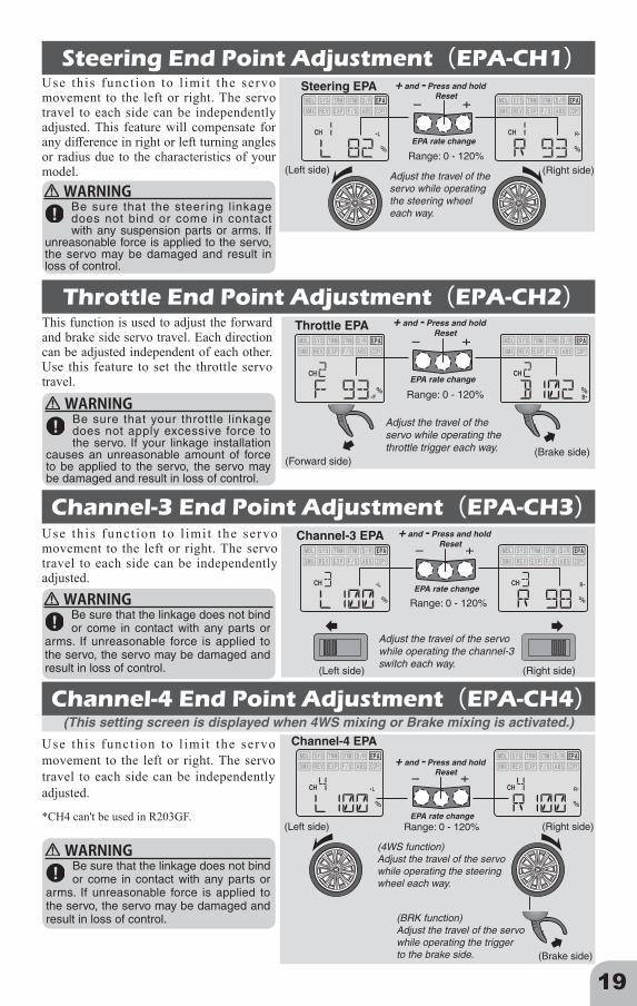
Use this funct ion to l imit the servo movement to the left or right. The servo travel to each side can be independently adjusted. This feature will compensate for any difference in right or left turning angles or radius due to the characteristics of your model.
(This setting screen is displayed when 4WS mixing or Brake mixing is activated.)
Steering End Point Adjustment(EPA-CH1)Steering EPA
Range: 0 - 120%(Left side) (Right side)
EPA rate change
+ and - Press and holdReset
Adjust the travel of the servo while operating the steering wheel each way.
This function is used to adjust the forward and brake side servo travel. Each direction can be adjusted independent of each other. Use this feature to set the throttle servo travel.
Throttle End Point Adjustment(EPA-CH2)
Range: 0 - 120%
EPA rate change
+ and - Press and holdReset
Throttle EPA
(Forward side)(Brake side)
Adjust the travel of the servo while operating the throttle trigger each way.
Channel-3 End Point Adjustment(EPA-CH3)Use th is funct ion to l imi t the servo movement to the left or right. The servo travel to each side can be independently adjusted.
Channel-3 EPA
Adjust the travel of the servowhile operating the channel-3 switch each way.
Range: 0 - 120%
(Left side) (Right side)
EPA rate change
+ and - Press and holdReset
Use this funct ion to l imit the servo movement to the left or right. The servo travel to each side can be independently adjusted.
WARNING
WARNING
WARNING
WARNING
Channel-4 End Point Adjustment(EPA-CH4)Channel-4 EPA
(4WS function)Adjust the travel of the servowhile operating the steering wheel each way.
(BRK function)Adjust the travel of the servowhile operating the triggerto the brake side.
Range: 0 - 120%(Left side) (Right side)
(Brake side)
EPA rate change
+ and - Press and holdReset
*CH4 can't be used in R203GF.
Be sure that the linkage does not bind or come in contact with any parts or
arms. If unreasonable force is applied to the servo, the servo may be damaged and result in loss of control.
Be sure that the linkage does not bind or come in contact with any parts or
arms. If unreasonable force is applied to the servo, the servo may be damaged and result in loss of control.
Be sure that your throttle linkage does not apply excessive force to the servo. If your linkage installation
causes an unreasonable amount of force to be applied to the servo, the servo may be damaged and result in loss of control.
Be sure that the steering linkage does not bind or come in contact with any suspension parts or arms. If
unreasonable force is applied to the servo, the servo may be damaged and result in loss of control.

20
Either 4WS mixing function or Brake mixing funct ion can be selected on this screen.*This function can't be used in R203GF.
4WS/BRK Mixing(SMX)
4WS Mixing (4WS)This mixing is used with Crawler and other 4WS specification cars. The 1st channel controls the front side steering and the 4th channel controls the rear side steering.• 4WS function selection1. After connecting the linkage, use the servo reverse function to change the
direction of operation of the front and rear wheels.2. Thereafter, use the end point adjuster to adjust the left and right steering
angles.
Brake Mixing (BRK)Use this mixing when the front and rear brakes must be adjusted independently, such as in 1/5GP cars, etc. This mixing uses the 2nd channel to control the rear brakes and the 4th channel to control the front brakes.
• When braking, mixing is applied to 2nd channel and to 4th channel.• The set value of A.B.S. function is reflected.
Steering Servo Reversing(REV-CH1)
Throttle Servo Reversing(REV-CH2)
Channel-3 Servo Reversing(REV-CH3)
NOR: NormalREV: Reverse
Steering Servo Reverse
Direction change
Throttle Servo Reverse
NOR: NormalREV: Reverse Direction change
Channel-3 Servo Reverse
NOR: NormalREV: Reverse Direction change
This function reverses the rotation direction of the Steering servo.
This function reverses the rotation direction of the throttle servo.
This function reverses the rotation direction of the channel-3 servo.
When the trim position deviates from the center, the deviation will be on the opposite side when the servo is reversed.
When the trim position deviates from the center, the deviation will be on the opposite side when the servo is reversed.
INH: Inhibited4WS: 4WS mixingBRK: Brake mixing for second brake
Special Mixing Selection
Mixing change
CH1
CH4

21
Channel-4 Servo Reversing(REV-CH4)Channel-4 Servo Reverse
NOR: NormalREV: Reverse Direction change
This function is used to change the sensitivity of the steering servo around the neutral position. It has no effect on the maximum servo travel.
This function reverses the rotation direction of the channel-4 servo.
When the trim position deviates from the center, the deviation will be on the opposite side when the servo is reversed.
*CH4 can't be used in R203GF.
Steering EXP(EXP-CH1)
[ - ] Minus → Around the neutral position is mild.
[ + ] Plus → Around the neutral position is quick.
Range: -100% ~ +100%
EXP rate change
+ and - Press and holdReset
Steering EXP
Racers Tip When the setting is not determined, or the characteristics of the model are unknown, start with 0%. (When EXP is set to 0%, servo movement is linear.)
This function changes the sensitivity of the throttle servo in the throttle trigger forward side and brake side directions. It has no effect on the servo maximum travel.
Throttle EXP(EXP-CH2)
Racers Tip When the track conditions are good and there is no sense of torque at the power unit, set the EXP to the + (quick) side. When the track is slippery and the drive wheels lose their grip, set the EXP to the - (mild) side.
Forward
Brake
Range: -100% ~ +100%EXP rate change
+ and - Press and holdReset
Range: -100% ~ +100%
EXP rate change
+ and - Press and holdReset
Throttle EXP
(Forward side)(Brake side)
Adjust the EXP while operating the throttle trigger each way.
ForwardBackBrake Trigger
Servo
+sideQuick
+sideQuick
-sideMild
-sideMild
(This setting screen is displayed when 4WS mixing or Brake mixing is activated.)

22
Throttle Fail Safe(F/S)This function moves the throttle servo to a preset position when the receiver cannot receive the signal from the transmitter for some reason.When the signal from the transmitter can be received again, this function automatically resets.
*For gasoline engine cars, it is recommended that the fail safe position be set to the direction that applies the brakes.
The contents of the currently selected model data can be copied to another model.
※ S-FHSS→Only 3.8V(Not change) FHSS→ Not battery F/S function
ExampleNiCd/NiMH 4 cell→3.8VNiCd/NiMH 6 cell→4.4VLiFe 2 cell→4.8VLiPo 2 cell→5.6VIt depends on your
receiver battery.
Throttle trigger to the desired position
Push the - key
Push the + key → F/S OFF
F/S Position
Throttle idle or brake position
F/S position setting
Battery F/S position setting (Only T-FHSS)
Key
Push the -(Minus) key while operating the throttle trigger to the desired position.
Setting example: Throttle idle or brake position
OFF: Inhibited3.8V-7.4V
Voltage change
ABS ABS Cycle SpeedOFF: InhibitedFST: Active (fast)MID: Active (middle)SLW: Active (slow)
ABS function
ABS change
This function simulates a full size car's antilock braking by pulsing the brake on and off rapidly. Model stops as rapidly as possible without skidding.•The cycle speed can be selected from FST/MID/SLW.
Model Data Copy(COPY)
The top (current model) is chosen with the steering.
Move (right or left) the DT1 about 1 second.
Copying
Select the current model numder with the (+) or (-) key.
Select the destination model numder with the (+) or (-) key.
The bottom (desti-nation model) is chosen with the steering.
Selection of copy model data Model copy execution
Model copy complete

23
Reference
Communication method:Two-way(T-FHSS)/One-way(S-FHSS,FHSS) operation system
Maximum operating range:80m (Optimum condition)
For safety: F/S (Throttle), ID
Transmitter T3PV-2.4G(T-FHSS/S-FHSS/FHSS system, wheel type, 3+1 channels)*The 4th channel is used for mixing functions only.Transmitting frequency:
2.4GHz bandPower requirement:
Size AA Dry cell battery x 4 (6V)Current drain:
100mA or lessTransmission antenna:
1/2λ di-pole (Built-in)
Receiver R203GF:(S-FHSS/FHSS auto detection system, 3 channels)Power requirement:
4.8V ~7.4V battery (Dry cell battery cannot be used.)Size:
1.54x1.02x0.39"(39x26x10mm)(excluding a projection part)
Weight: 0.28oz.(8g)
Receiver R304SB/R314SB:(T-FHSS system, 4 channels)Power requirement:
4.8V ~7.4V battery (Dry cell battery cannot be used.)Size:
1.38x0.91x0.33"(35.1x23.2x8.5mm)(excluding a projection part)
Weight: 0.23oz.(6.6g )
*Specifications and ratings are subject to change without prior notice.
NOTE: This Futaba T-FHSS/S-FHSS/FHSS system, does not work with current Futaba FASST™ systems. Futaba FASST systems and T-FHSS/T-FHSS/S-FHSS/FHSS systems are not compatible.
Ratings
When Requesting RepairBefore requesting repair, read this instruction again and recheck your system. Should the problems continue, request as follows.(Information needed for repair)Describe the problem in as much detail as possible and send the letter along with the system in question.• Symptom (Including the conditions and when the
problem occurred)• R/C System (Send transmitter, receiver and servos)• Model (Type of model, brand name and model number or
kit name)• Detailed packing list (Make a list of all items sent in for
repair)• Your name, address and telephone number.(Warranty)Read the Warranty card.• When requesting warranty service, send the card or some type of dated proof of purchase.Hobby Services (U.S. only)
3002 N Apollo Drive Suite 1, Champaign, IL 61822 U.S.ATEL (217)398-8970 or E-mail: [email protected] (Support) TEL (217)398-0007 or E-mail: [email protected] (Service)
©Copyright 2016. No part of this manual may be reproduced in any form without prior permission. The contents of this manual are subject to change without prior notice. While this manual has been carefully written, there may be inadvertent errors or omissions. Please contact our service center if you feel that any corrections or clarifications should be made.
FUTABA CORPORATION Phone: +81 475 32 6982, Facsimile: +81 475 32 69831080 Yabutsuka, Chosei-mura, Chosei-gun, Chiba 299-4395, Japan
©FUTABA CORPORATION 2016, 5 (3)