Embed Size (px)
Citation preview
6 July. 2017
Photo by K.Okano
Satoshi Konishi, Kyoto University
1st IAEA workshop on
“Challenges for coolants in fast spectrum system:
Chemistry and materials”
With contributions by: M. Enoeda, K.Tobita, M.Nakajima, T.Nozawa, H.Tanigawa,
and T.Hirose in QST.
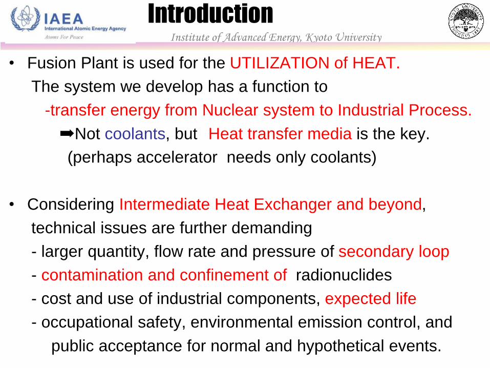
• Fusion Plant is used for the UTILIZATION of HEAT.
The system we develop has a function to
-transfer energy from Nuclear system to Industrial Process.
➡Not coolants, but Heat transfer media is the key.
(perhaps accelerator needs only coolants)
• Considering Intermediate Heat Exchanger and beyond,
technical issues are further demanding
- larger quantity, flow rate and pressure of secondary loop
- contamination and confinement of radionuclides
- cost and use of industrial components, expected life
- occupational safety, environmental emission control, and
public acceptance for normal and hypothetical events.
Introduction Institute of Advanced Energy, Kyoto University
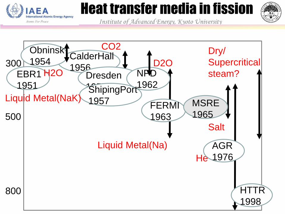
温度 熱効率
300
500
800
CO2
D2O
Salt
Liquid Metal(Na)
He
Dry/
Supercritical
steam?
CalderHall
1956
Obninsk
1954
Dresden
1957
EBR1
1951
NPD
1962
FERMI
1963
AGR
1976
MSRE
1965
H2O
Heat transfer media in fission Institute of Advanced Energy, Kyoto University
ShipingPort
1957 Liquid Metal(NaK)
HTTR
1998
Institute of Advanced Energy, Kyoto University
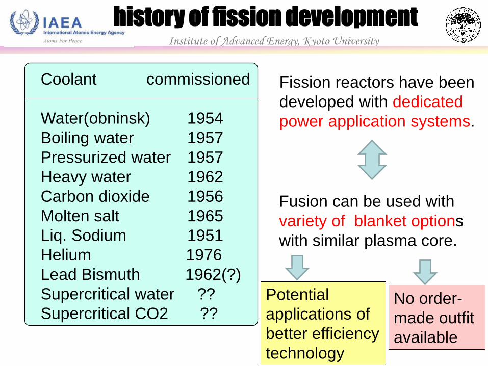
history of fission development
Coolant commissioned
Water(obninsk) 1954
Boiling water 1957
Pressurized water 1957
Heavy water 1962
Carbon dioxide 1956
Molten salt 1965
Liq. Sodium 1951
Helium 1976
Lead Bismuth 1962(?)
Supercritical water ??
Supercritical CO2 ??
Fission reactors have been
developed with dedicated
power application systems.
Fusion can be used with
variety of blanket options
with similar plasma core.
Potential
applications of
better efficiency
technology
No order-
made outfit
available
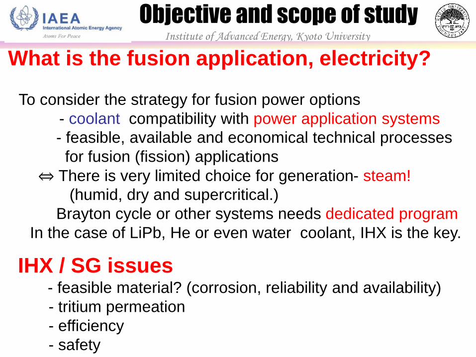
What is the fusion application, electricity?
To consider the strategy for fusion power options
- coolant compatibility with power application systems
- feasible, available and economical technical processes
for fusion (fission) applications
⇔ There is very limited choice for generation- steam!
(humid, dry and supercritical.)
Brayton cycle or other systems needs dedicated program
In the case of LiPb, He or even water coolant, IHX is the key.
IHX / SG issues - feasible material? (corrosion, reliability and availability)
- tritium permeation
- efficiency
- safety
Objective and scope of study Institute of Advanced Energy, Kyoto University
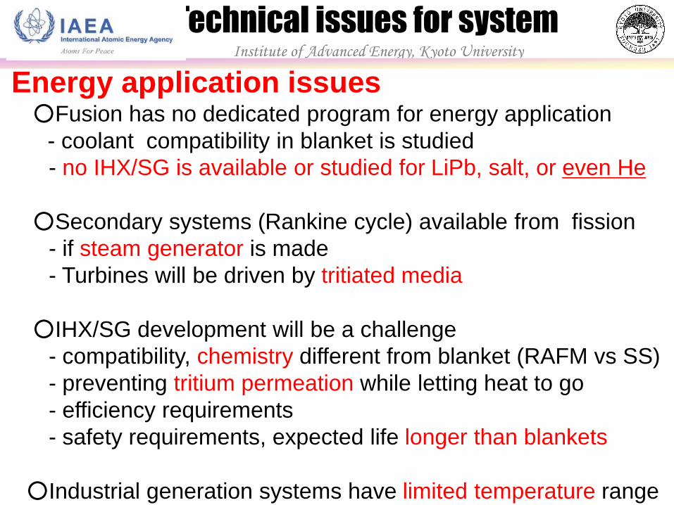
Energy application issues
○Fusion has no dedicated program for energy application
- coolant compatibility in blanket is studied
- no IHX/SG is available or studied for LiPb, salt, or even He
○Secondary systems (Rankine cycle) available from fission
- if steam generator is made
- Turbines will be driven by tritiated media
○IHX/SG development will be a challenge
- compatibility, chemistry different from blanket (RAFM vs SS)
- preventing tritium permeation while letting heat to go
- efficiency requirements
- safety requirements, expected life longer than blankets
○Industrial generation systems have limited temperature range
Technical issues for system Institute of Advanced Energy, Kyoto University
Institute of Advanced Energy, Kyoto University
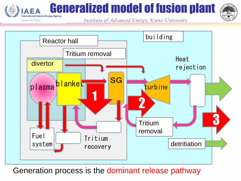
Generalized model of fusion plant
plasma blanket SG
turbine
Heat rejection
Tritium recovery
Reactor hall
divertor
Fuel system
building
Tritium removal
Generation process is the dominant release pathway
1 2
3 Tritium
removal
detritiation
Institute of Advanced Energy, Kyoto University
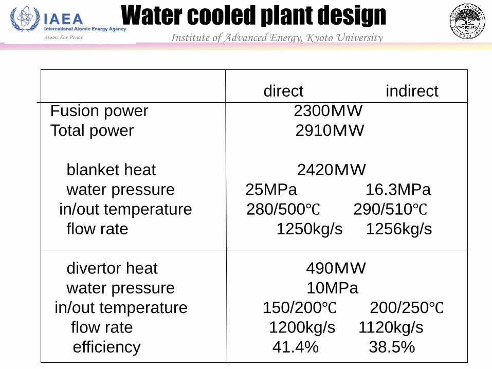
Water cooled plant design
direct indirect
Fusion power 2300MW
Total power 2910MW
blanket heat 2420MW
water pressure 25MPa 16.3MPa
in/out temperature 280/500℃ 290/510℃
flow rate 1250kg/s 1256kg/s
divertor heat 490MW
water pressure 10MPa
in/out temperature 150/200℃ 200/250℃
flow rate 1200kg/s 1120kg/s
efficiency 41.4% 38.5%
Institute of Advanced Energy, Kyoto University
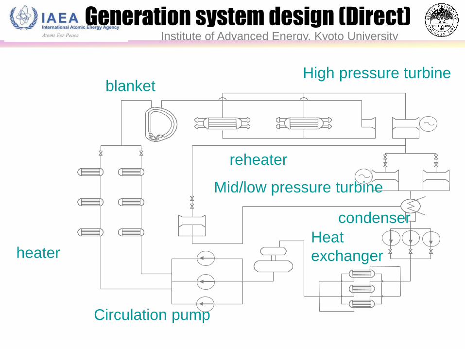
blanket
reheater
Heat
exchanger heater
High pressure turbine
Circulation pump
condenser
Generation system design (Direct)
Mid/low pressure turbine
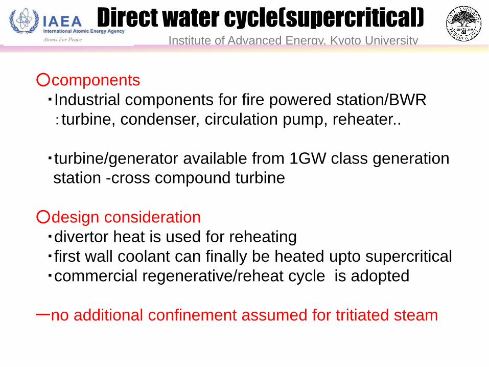
○components
・Industrial components for fire powered station/BWR
:turbine, condenser, circulation pump, reheater..
・turbine/generator available from 1GW class generation
station -cross compound turbine
○design consideration
・divertor heat is used for reheating
・first wall coolant can finally be heated upto supercritical
・commercial regenerative/reheat cycle is adopted
ーno additional confinement assumed for tritiated steam
Institute of Advanced Energy, Kyoto University
Direct water cycle(supercritical)
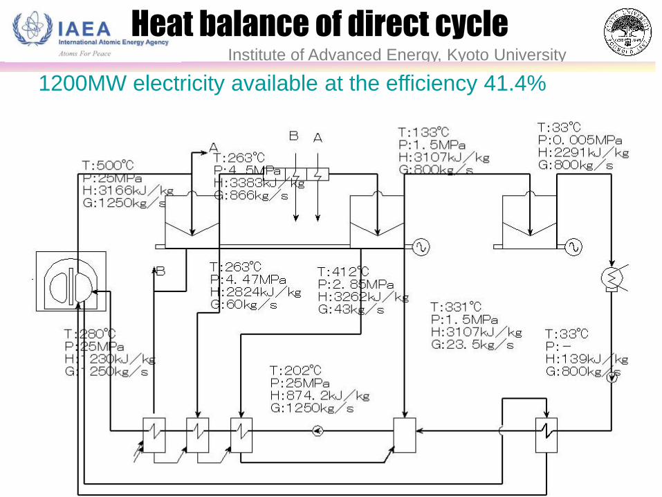
1200MW electricity available at the efficiency 41.4%
Institute of Advanced Energy, Kyoto University
Heat balance of direct cycle
blanket reheater turbine
To water detritiation
Steam Generator
Booster pump
feed water heater
(from divertor)
CVCS Circulation pump
Institute of Advanced Energy, Kyoto University
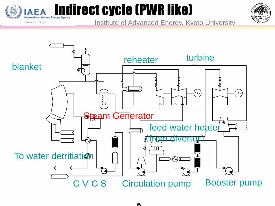
Indirect cycle (PWR like)
○components
・Assuming components for PWR and FBR be available
・Dedicated Steam Generator and CVCS
○Design consideration
・Divertor heat is used for reheating at low temperature
・Steam generator different from PWR
-helical coil tubes for FBR
-superheated steam at 25MPa
ーtritium concentration for turbine reduced ~4 order
○efficiency
・1120MW electricity at 38.5%efficiency
Institute of Advanced Energy, Kyoto University
Indirect water cycle
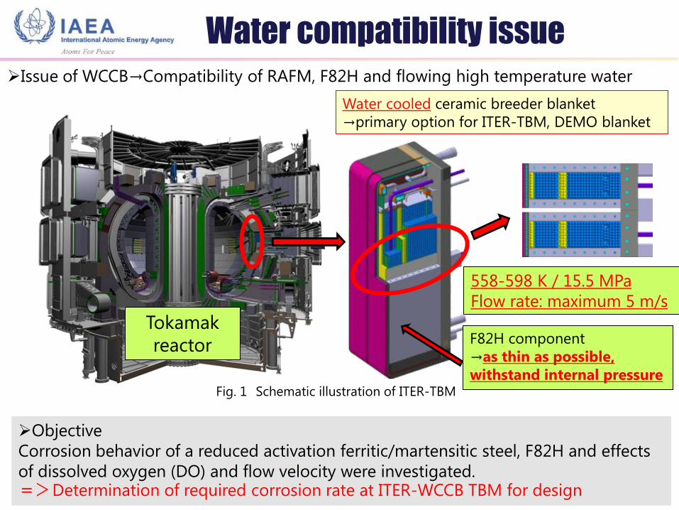
Issue of WCCB→Compatibility of RAFM, F82H and flowing high temperature water
Objective
Corrosion behavior of a reduced activation ferritic/martensitic steel, F82H and effects
of dissolved oxygen (DO) and flow velocity were investigated. =>Determination of required corrosion rate at ITER-WCCB TBM for design
558-598 K / 15.5 MPa
Flow rate: maximum 5 m/s
Fig. 1 Schematic illustration of ITER-TBM
Water cooled ceramic breeder blanket
→primary option for ITER-TBM, DEMO blanket
Tokamak
reactor F82H component
→as thin as possible,
withstand internal pressure
Water compatibility issue
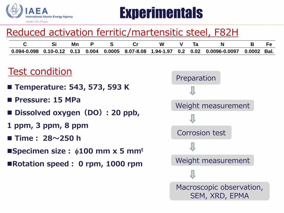
C Si Mn P S Cr W V Ta N B Fe
0.094-0.098 0.10-0.12 0.13 0.004 0.0005 8.07-8.08 1.94-1.97 0.2 0.02 0.0096-0.0097 0.0002 Bal.
Reduced activation ferritic/martensitic steel, F82H
Temperature: 543, 573, 593 K
Pressure: 15 MPa
Dissolved oxygen(DO): 20 ppb,
1 ppm, 3 ppm, 8 ppm
Time: 28~250 h
Specimen size: f100 mm x 5 mmt
Rotation speed: 0 rpm, 1000 rpm
Test condition
Preparation
Weight measurement
Corrosion test
Macroscopic observation, SEM, XRD, EPMA
Weight measurement
Experimentals
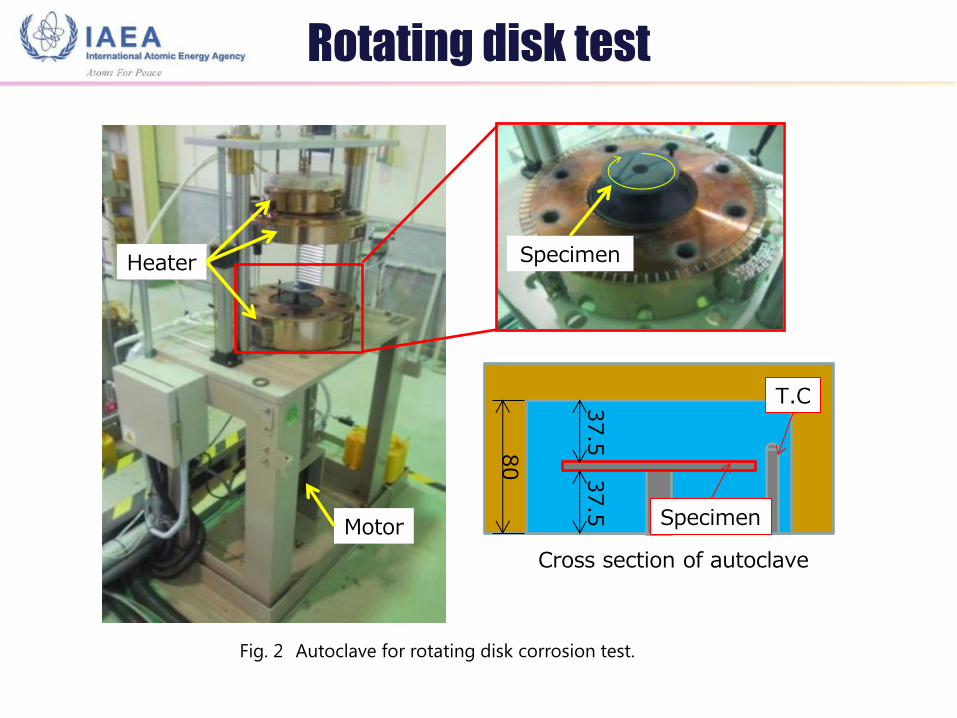
Rotating disk test
Heater
Motor
Specimen
Specimen
T.C
80
37.5
37.5
Cross section of autoclave
Fig. 2 Autoclave for rotating disk corrosion test.
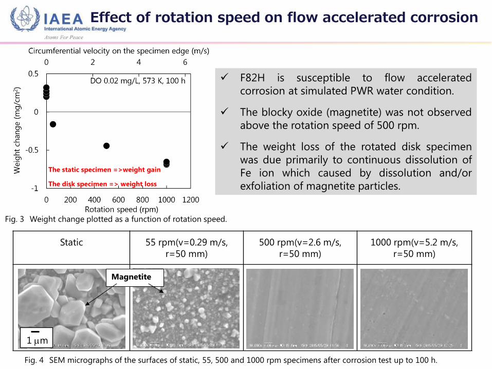
Static 55 rpm(v=0.29 m/s,
r=50 mm)
500 rpm(v=2.6 m/s,
r=50 mm)
1000 rpm(v=5.2 m/s,
r=50 mm)
F82H is susceptible to flow accelerated
corrosion at simulated PWR water condition.
The blocky oxide (magnetite) was not observed
above the rotation speed of 500 rpm.
The weight loss of the rotated disk specimen
was due primarily to continuous dissolution of
Fe ion which caused by dissolution and/or
exfoliation of magnetite particles.
1 mm
Fig. 4 SEM micrographs of the surfaces of static, 55, 500 and 1000 rpm specimens after corrosion test up to 100 h.
Magnetite
The static specimen =>weight gain
The disk specimen => weight loss
Fig. 3 Weight change plotted as a function of rotation speed.
Effect of rotation speed on flow accelerated corrosion
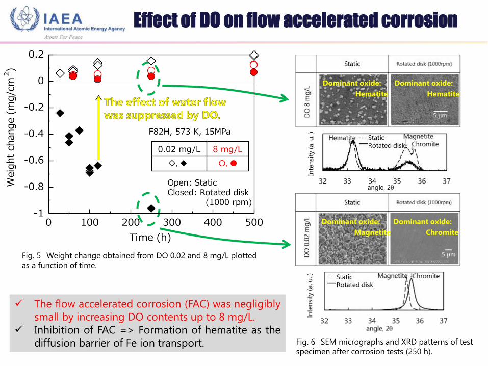
Fig. 5 Weight change obtained from DO 0.02 and 8 mg/L plotted
as a function of time.
Fig. 6 SEM micrographs and XRD patterns of test
specimen after corrosion tests (250 h).
Dominant oxide:
Magnetite
Dominant oxide:
Chromite
Dominant oxide:
Hematite
Dominant oxide:
Hematite
The flow accelerated corrosion (FAC) was negligibly
small by increasing DO contents up to 8 mg/L.
Inhibition of FAC => Formation of hematite as the
diffusion barrier of Fe ion transport.
Effect of DO on flow accelerated corrosion
0.02 mg/L 8 mg/L
◆ ●
0 100 200 300 400 500-1
-0.8
-0.6
-0.4
-0.2
0
0.2
Time (h)
Weig
ht
change (
mg/c
m2)
F82H, 573 K, 15MPa
Open: Static Closed: Rotated disk (1000 rpm)
◇, ◆ ○, ●
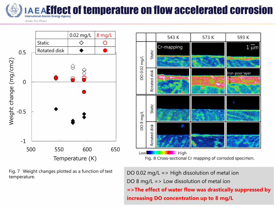
Fig. 7 Weight changes plotted as a function of test
temperature. DO 0.02 mg/L => High dissolution of metal ion
DO 8 mg/L => Low dissolution of metal ion
=>The effect of water flow was drastically suppressed by
increasing DO concentration up to 8 mg/L
Effect of temperature on flow accelerated corrosion W
eig
ht
change (
mg/c
m2)
Temperature (K)
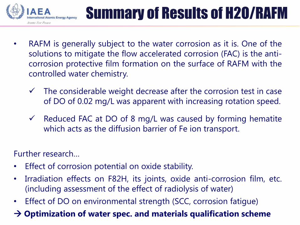
• RAFM is generally subject to the water corrosion as it is. One of the
solutions to mitigate the flow accelerated corrosion (FAC) is the anti-
corrosion protective film formation on the surface of RAFM with the
controlled water chemistry.
The considerable weight decrease after the corrosion test in case
of DO of 0.02 mg/L was apparent with increasing rotation speed.
Reduced FAC at DO of 8 mg/L was caused by forming hematite
which acts as the diffusion barrier of Fe ion transport.
Further research…
• Effect of corrosion potential on oxide stability.
• Irradiation effects on F82H, its joints, oxide anti-corrosion film, etc.
(including assessment of the effect of radiolysis of water)
• Effect of DO on environmental strength (SCC, corrosion fatigue)
Optimization of water spec. and materials qualification scheme
Summary of Results of H2O/RAFM
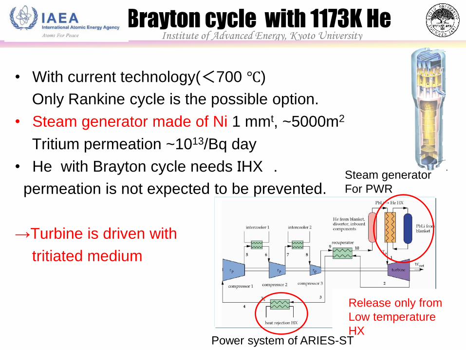
• With current technology(<700 ℃)
Only Rankine cycle is the possible option.
• Steam generator made of Ni 1 mmt, ~5000m2
Tritium permeation ~1013/Bq day
• He with Brayton cycle needs IHX .
permeation is not expected to be prevented.
→Turbine is driven with
tritiated medium
Release only from
Low temperature
HX
Steam generator
For PWR
Power system of ARIES-ST
Brayton cycle with 1173K He Institute of Advanced Energy, Kyoto University
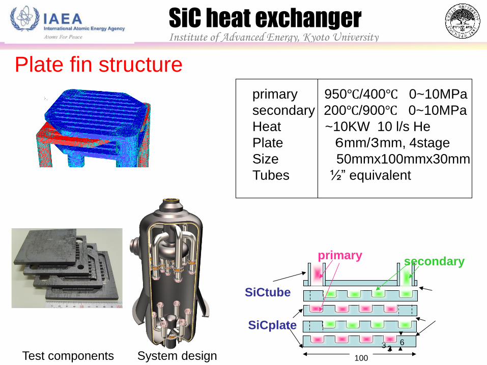
Plate fin structure
100
6 3 3
SiCtube
SiCplate
secondary primary
primary 950℃/400℃ 0~10MPa
secondary 200℃/900℃ 0~10MPa
Heat ~10KW 10 l/s He
Plate 6mm/3mm, 4stage
Size 50mmx100mmx30mm
Tubes ½” equivalent
Test components System design
SiC heat exchanger Institute of Advanced Energy, Kyoto University
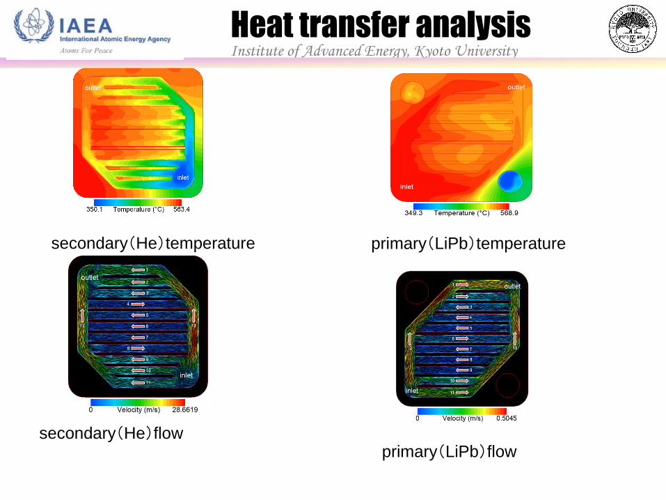
secondary(He)temperature primary(LiPb)temperature
Institute of Advanced Energy, Kyoto University Heat transfer analysis
secondary(He)flow primary(LiPb)flow
Institute of Advanced Energy, Kyoto University
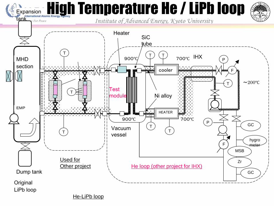
He-LiPb loop
EMP
T
T
Dump tank
T
T
T
hygro
meter
cooler
HEATER
GC
T
Used for
Other project He loop (other project for IHX)
P
F
F
P
MSB
Zr
GC
T
T
Heater
900℃
900℃ 700℃
700℃
~200℃
Ni alloy
Test
module
Vacuum
vessel
High Temperature He / LiPb loop Expansion
tank
Original
LiPb loop
MHD
section
SiC
tube
IHX
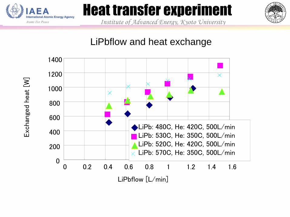
LiPbflow and heat exchange
0
200
400
600
800
1000
1200
1400
0 0.2 0.4 0.6 0.8 1 1.2 1.4 1.6
LiPbflow [L/min]
Exc
hang
ed h
eat
[W]
LiPb: 480C, He: 420C, 500L/min
LiPb: 520C, He: 420C, 500L/min
LiPb: 530C, He: 350C, 500L/min
LiPb: 570C, He: 350C, 500L/min
Institute of Advanced Energy, Kyoto University
Heat transfer experiment
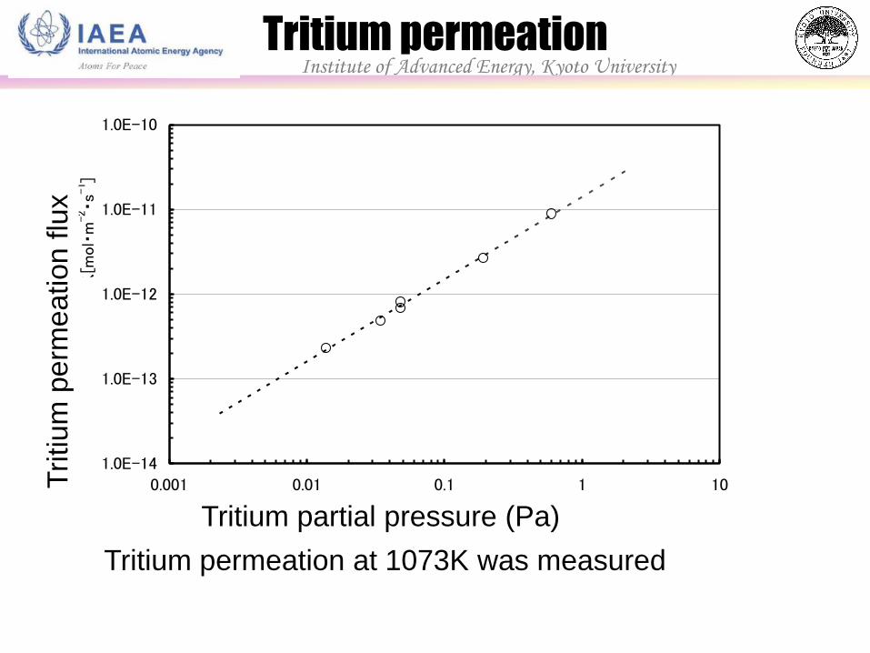
1.0E-14
1.0E-13
1.0E-12
1.0E-11
1.0E-10
0.001 0.01 0.1 1 10
トリチウム分圧[Pa]
定常透過フラックス[mol・m
-2・s
-1]
Tritium permeation at 1073K was measured
Institute of Advanced Energy, Kyoto University Tritium permeation
Tritium partial pressure (Pa)
Tritium
perm
eation f
lux
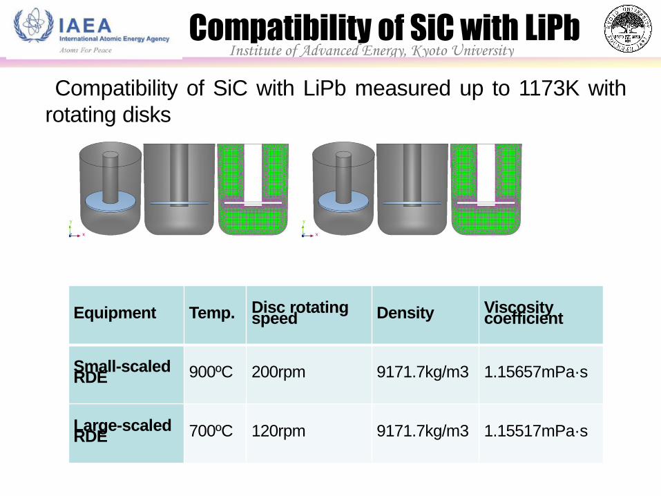
Institute of Advanced Energy, Kyoto University Compatibility of SiC with LiPb
Compatibility of SiC with LiPb measured up to 1173K with
rotating disks
Equipment Temp. Disc rotating speed Density Viscosity
coefficient
Small-scaled RDE 900ºC 200rpm 9171.7kg/m3 1.15657mPa·s
Large-scaled RDE 700ºC 120rpm 9171.7kg/m3 1.15517mPa·s
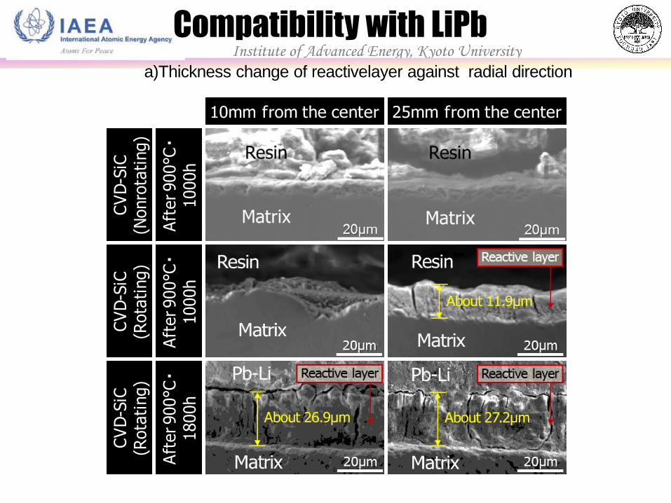
Institute of Advanced Energy, Kyoto University Compatibility with LiPb
a)Thickness change of reactivelayer against radial direction
10mm from the center 25mm from the centerC
VD
-SiC
(Nonro
tati
ng)
Aft
er 900°C・
1000h
CV
D-S
iC(R
ota
ting)
Aft
er 900°C・
1000h
CV
D-S
iC(R
ota
ting)
Aft
er 900°C・
1800h
20mm from the center 40mm from the center
CV
I-SiC
/SiC
(Rota
ting)
Aft
er 700°C・
1000h・M
atr
ix
CV
I-SiC
/SiC
(Rota
ting)
Aft
er 700°C・
3000h・M
atr
ix
CV
I-SiC
/SiC
(Rota
ting)
Aft
er 700°C・
3000h・Fib
er
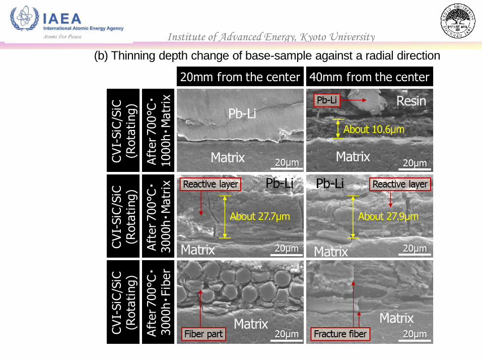
(b) Thinning depth change of base-sample against a radial direction
Institute of Advanced Energy, Kyoto University
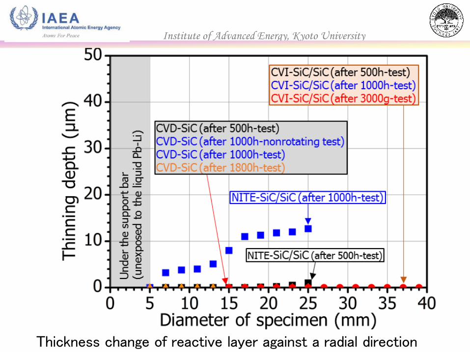
Thickness change of reactive layer against a radial direction
Institute of Advanced Energy, Kyoto University
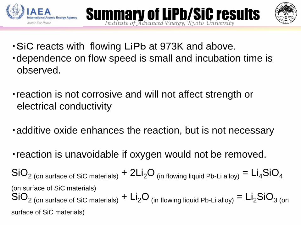
SiO2 (on surface of SiC materials) + 2Li2O (in flowing liquid Pb-Li alloy) = Li4SiO4
(on surface of SiC materials)
SiO2 (on surface of SiC materials) + Li2O (in flowing liquid Pb-Li alloy) = Li2SiO3 (on
surface of SiC materials)
Institute of Advanced Energy, Kyoto University Summary of LiPb/SiC results
・SiC reacts with flowing LiPb at 973K and above.
・dependence on flow speed is small and incubation time is
observed.
・reaction is not corrosive and will not affect strength or
electrical conductivity
・additive oxide enhances the reaction, but is not necessary
・reaction is unavoidable if oxygen would not be removed.

After
Before
SiC/SiC composite F82H SUS316
After
Before
SiC/SiC composite F82H SUS316
SiC with
supercritical water
Before the test 5MPa,100h 5MPa,300h
8MPa,100h
8MPa,300h
SiC with supercritical CO2
→corrosion observed →no change observed
Institute of Advanced Energy, Kyoto University Compatibility with other media
Drain/
cooling tower
Stack
/scrubber
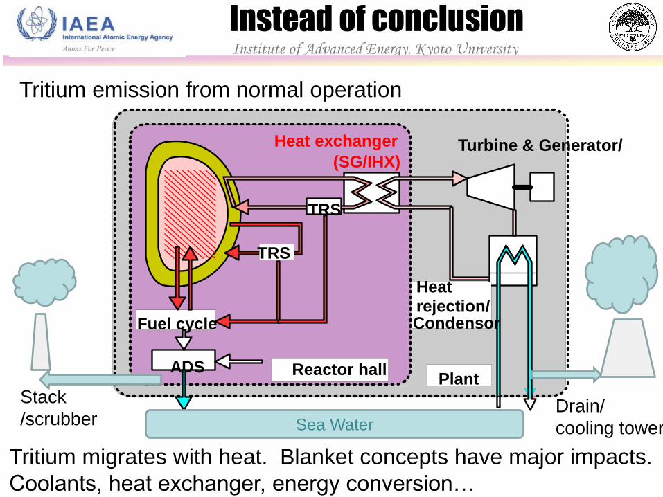
Tritium migrates with heat. Blanket concepts have major impacts.
Coolants, heat exchanger, energy conversion…
Fuel cycle
Heat rejection/ Condensor
Heat exchanger
(SG/IHX)
ADS
TRS
Reactor hall Plant
Turbine & Generator/
TRS
Sea Water
Institute of Advanced Energy, Kyoto University
Instead of conclusion
Tritium emission from normal operation
Institute of Advanced Energy, Kyoto University
Drain/
cooling tower
Stack
/scrubber
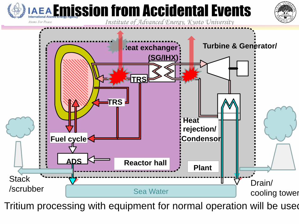
Tritium processing with equipment for normal operation will be used.
Emission from Accidental Events
Fuel cycle
Heat rejection/
Condensor
Heat exchanger
(SG/IHX)
ADS
TRS
Reactor hall Plant
Turbine & Generator/
TRS
Sea Water
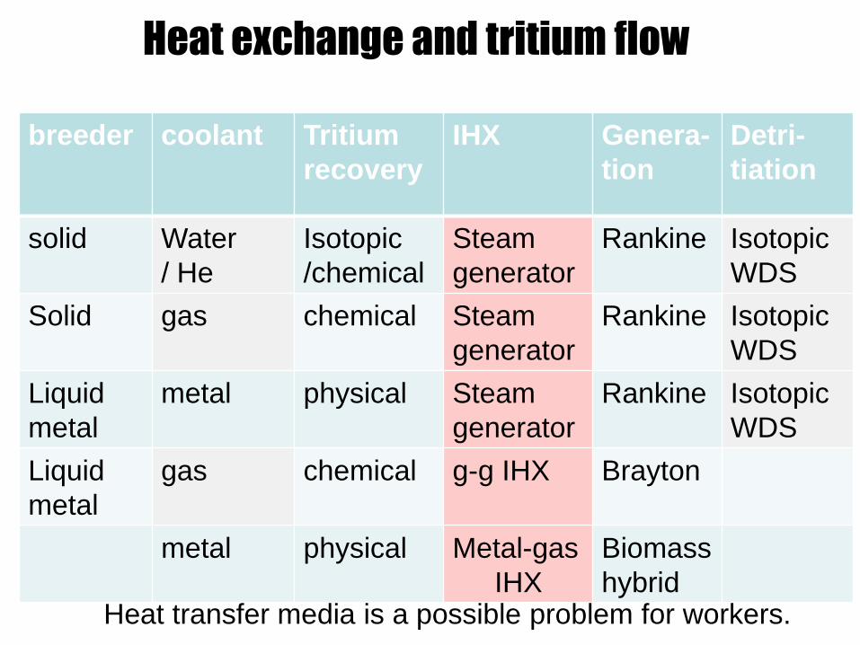
Heat exchange and tritium flow
breeder coolant Tritium
recovery
IHX Genera-
tion
Detri-
tiation
solid Water
/ He
Isotopic
/chemical
Steam
generator
Rankine Isotopic
WDS
Solid gas chemical Steam
generator
Rankine
Isotopic
WDS
Liquid
metal
metal physical Steam
generator
Rankine
Isotopic
WDS
Liquid
metal
gas chemical g-g IHX
Brayton
metal physical Metal-gas
IHX
Biomass
hybrid Heat transfer media is a possible problem for workers.
Institute of Advanced Energy, Kyoto University
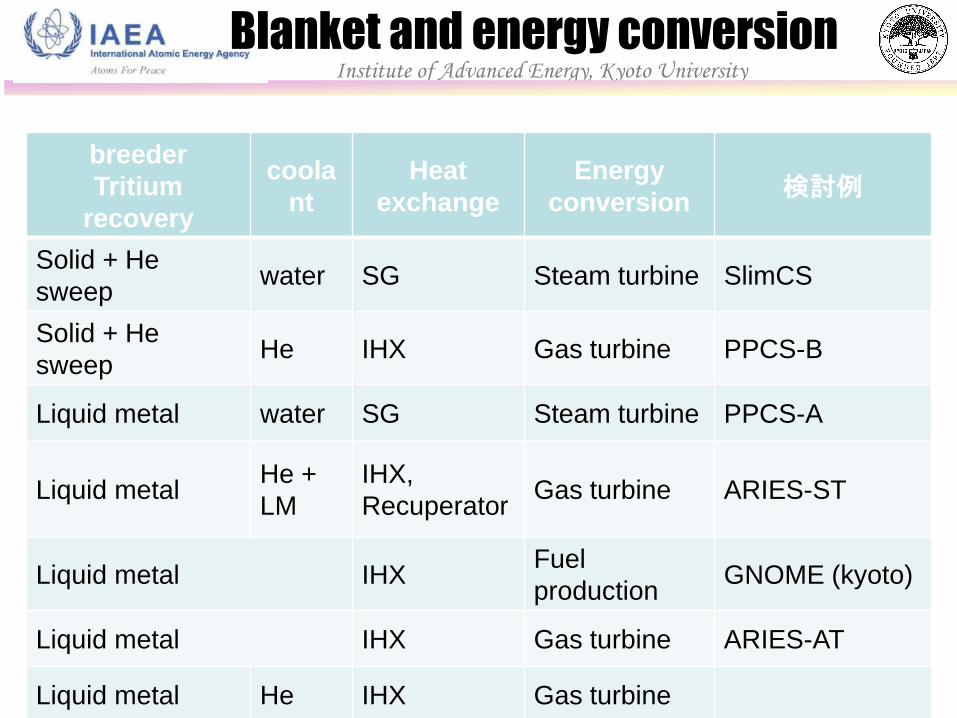
breeder
Tritium
recovery
coola
nt
Heat
exchange
Energy
conversion 検討例
Solid + He
sweep water SG Steam turbine SlimCS
Solid + He
sweep He IHX Gas turbine PPCS-B
Liquid metal water SG Steam turbine PPCS-A
Liquid metal He +
LM
IHX,
Recuperator Gas turbine ARIES-ST
Liquid metal IHX Fuel
production GNOME (kyoto)
Liquid metal IHX Gas turbine ARIES-AT
Liquid metal He IHX Gas turbine
Blanket and energy conversion
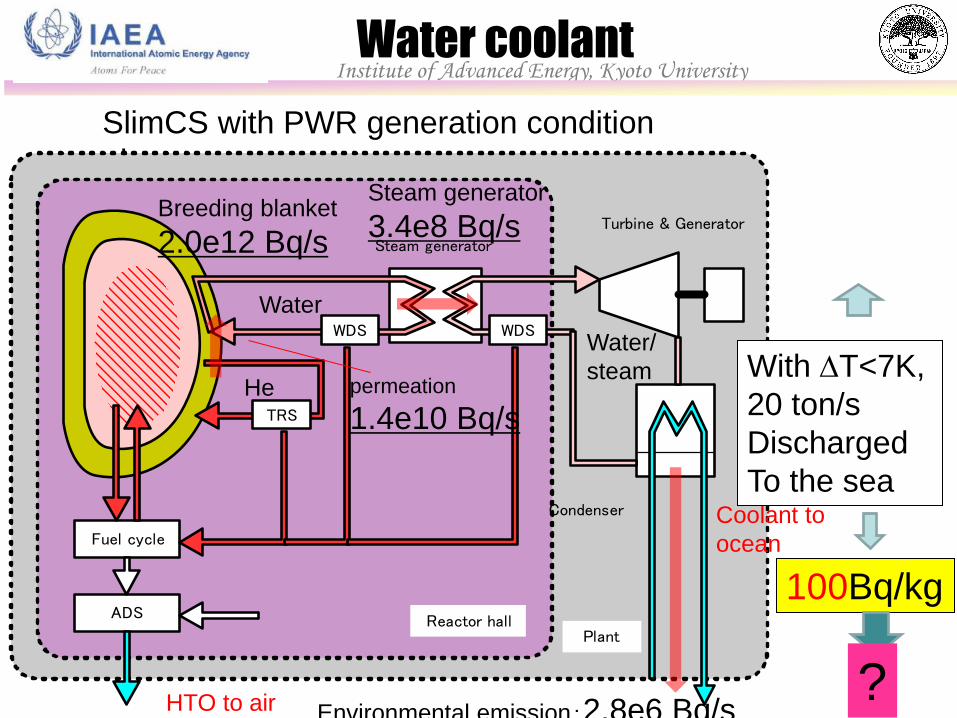
SlimCS with PWR generation condition
plant
Fuel cycle
Condenser
Steam generator
ADS
TRS
Reactor hallPlant
Turbine & Generator
WDS WDS
Breeding blanket
2.0e12 Bq/s
permeation
1.4e10 Bq/s
Water
Water/
steam He
Steam generator
3.4e8 Bq/s
Environmental emission:2.8e6 Bq/s HTO to air
Coolant to
ocean
Water coolant
With DT<7K,
20 ton/s
Discharged
To the sea
100Bq/kg
?
Institute of Advanced Energy, Kyoto University
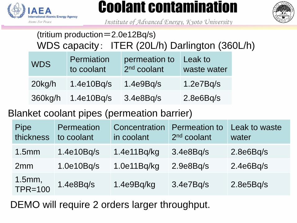
(tritium production=2.0e12Bq/s)
WDS capacity: ITER (20L/h) Darlington (360L/h)
WDS Permiation
to coolant
permeation to
2nd coolant
Leak to
waste water
20kg/h 1.4e10Bq/s 1.4e9Bq/s 1.2e7Bq/s
360kg/h 1.4e10Bq/s 3.4e8Bq/s 2.8e6Bq/s
Pipe
thickness
Permeation
to coolant
Concentration
in coolant
Permeation to
2nd coolant
Leak to waste
water
1.5mm 1.4e10Bq/s 1.4e11Bq/kg 3.4e8Bq/s 2.8e6Bq/s
2mm 1.0e10Bq/s 1.0e11Bq/kg 2.9e8Bq/s 2.4e6Bq/s
1.5mm,
TPR=100 1.4e8Bq/s 1.4e9Bq/kg 3.4e7Bq/s 2.8e5Bq/s
Blanket coolant pipes (permeation barrier)
DEMO will require 2 orders larger throughput.
Coolant contamination Institute of Advanced Energy, Kyoto University
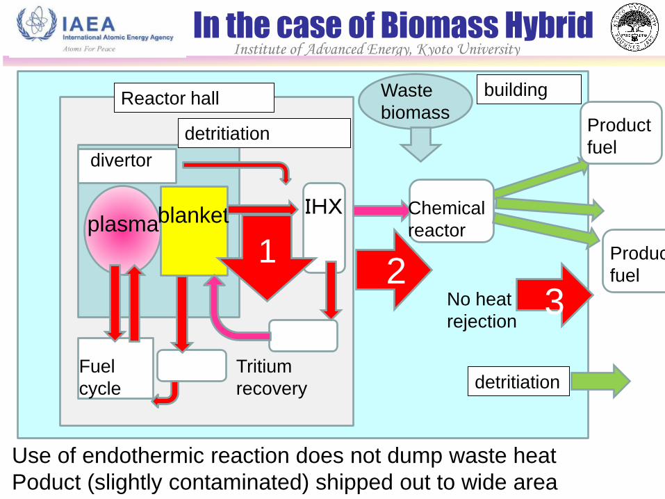
In the case of Biomass Hybrid
plasma blanket IHX
Tritium
recovery
Reactor hall
divertor
Fuel
cycle
building
detritiation
Use of endothermic reaction does not dump waste heat
Poduct (slightly contaminated) shipped out to wide area
1 2
3
detritiation
Chemical
reactor
Product
fuel
No heat
rejection
Waste
biomass
Product
fuel
Institute of Advanced Energy, Kyoto University
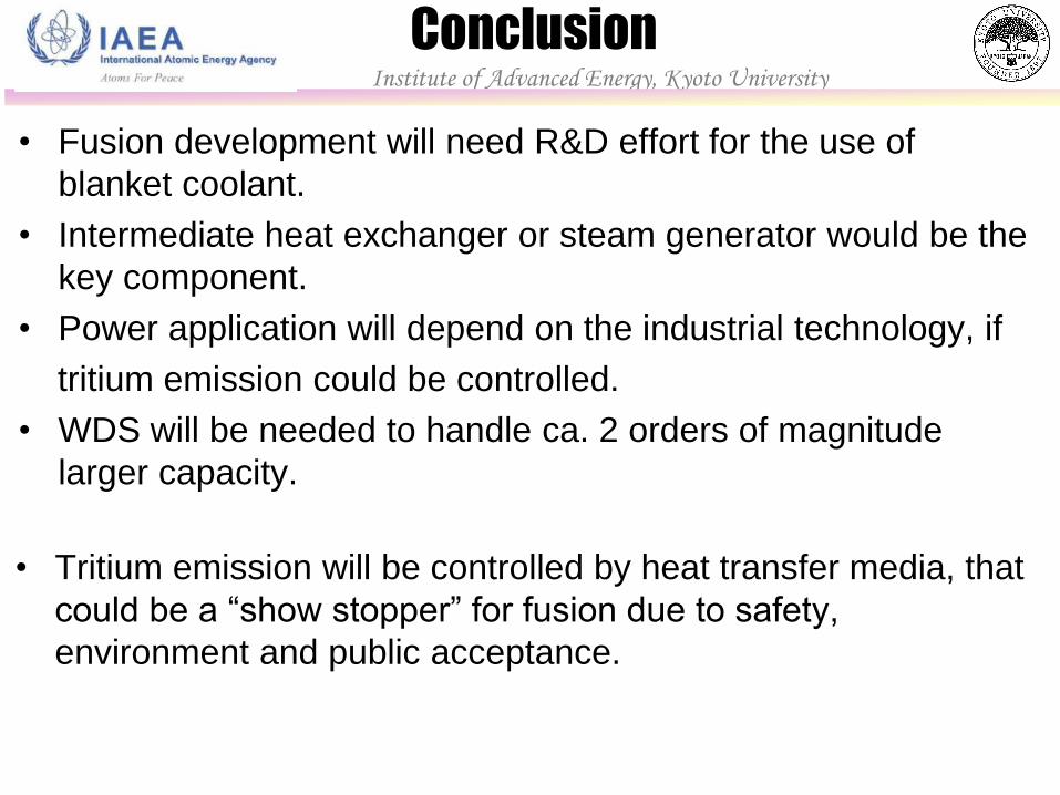
Conclusion
• Tritium emission will be controlled by heat transfer media, that
could be a “show stopper” for fusion due to safety,
environment and public acceptance.
Institute of Advanced Energy, Kyoto University
• Fusion development will need R&D effort for the use of
blanket coolant.
• Intermediate heat exchanger or steam generator would be the
key component.
• Power application will depend on the industrial technology, if
tritium emission could be controlled.
• WDS will be needed to handle ca. 2 orders of magnitude
larger capacity.

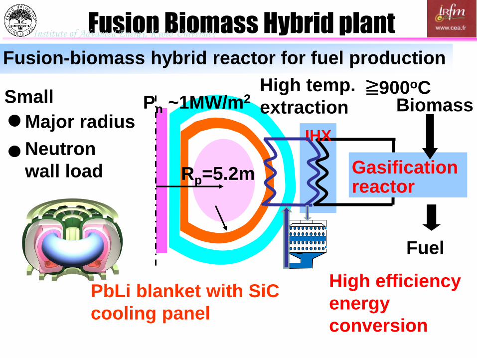
Fusion-biomass hybrid reactor for fuel production
Fusion Biomass Hybrid plant
Rp=5.2m Gasification reactor
Biomass
Fuel
Pn ~1MW/m2
Neutron
wall load
Major radius
Small ≧900oC High temp.
extraction
High efficiency
energy
conversion
PbLi blanket with SiC
cooling panel
IHX
Institute of Advanced Energy, Kyoto University
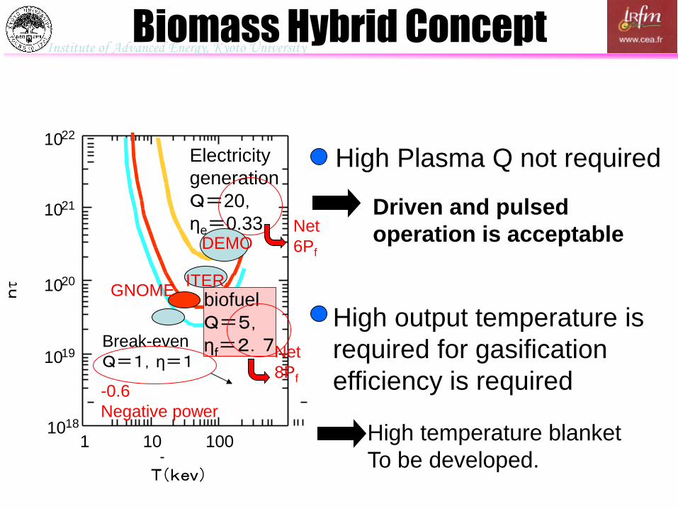
High Plasma Q not required
18 10
10 22
10 21
10 20
10 19
1 10 100
T(kev)
Break-even
Q=1,η=1
Electricity
generation
Q=20,
ηe=0.33
biofuel
Q=5,
ηf=2.7
-0.6
Negative power
ITER
DEMO
Driven and pulsed
operation is acceptable
High temperature blanket
To be developed.
High output temperature is
required for gasification
efficiency is required
Biomass Hybrid Concept
Net
6Pf
Net
8Pf
GNOME
Institute of Advanced Energy, Kyoto University
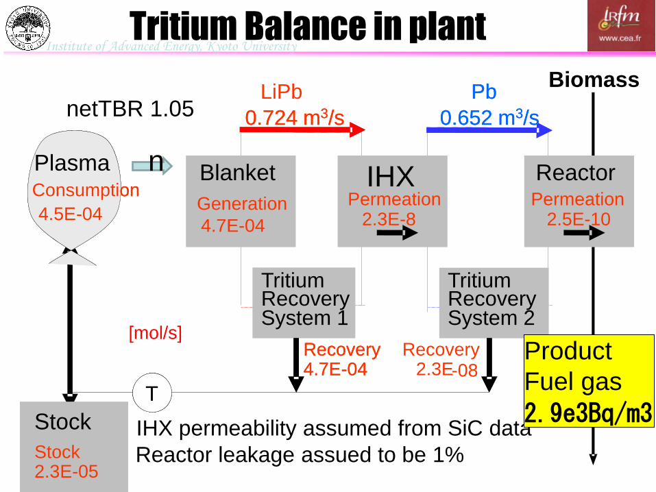
Tritium Balance in plant
Biomass
HEX
Tritium
4.5E - 04
LiPb Pb
Recovery System 1
Tritium Recovery System 2
Reactor Plasma
T
2.3 E - 8
2.3E
2.5 E - 10
4.7E - 04
0.724 m 3 /s 0.652 m 3 /s
Permeation
Recovery
Consumption Blanket
4. 7 E - 04
Generation Permeation IHX
Tritium
4.5E - 04
Pb
Recovery System 1
Tritium Recovery System 2
Reactor Plasma
T T
2.3 E - 8
-08
2.5 E - 10
4.7E - 04
0.724 m 3 /s 0.652 m 3 /s
Permeation
Recovery
Consumption
Stock
2.3 E - 0 5 Stock
Stock
2.3 E - 0 5 Stock
[mol/s] Recovery
Blanket
4. 7 E - 04
Generation Permeation
IHX permeability assumed from SiC data
Reactor leakage assued to be 1%
netTBR 1.05
n
Product
Fuel gas
2.9e3Bq/m3
Institute of Advanced Energy, Kyoto University
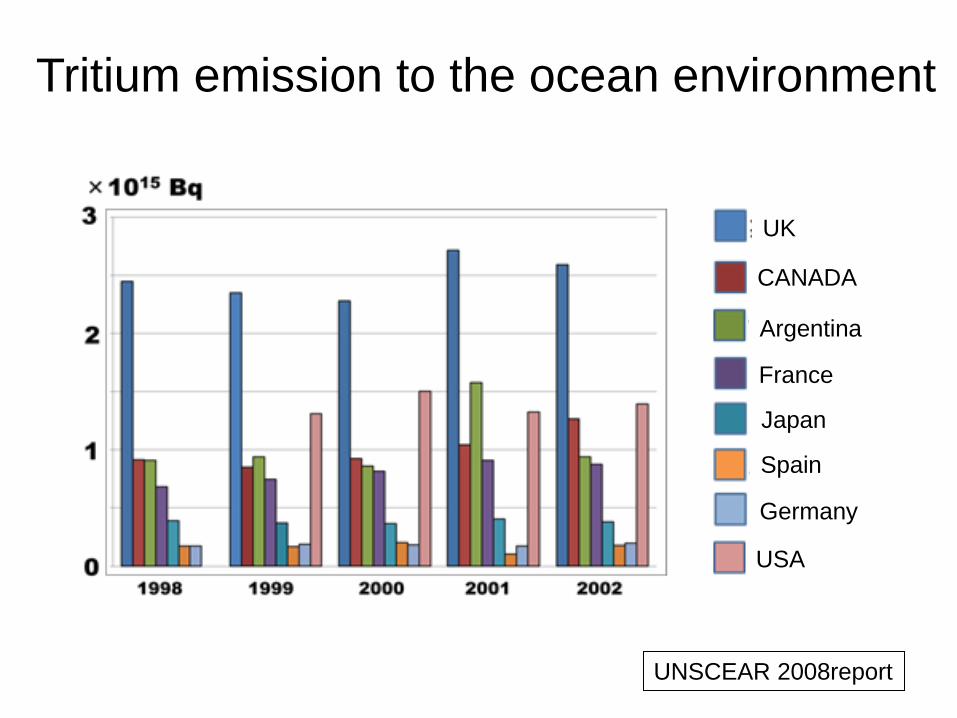
UNSCEAR 2008report
Tritium emission to the ocean environment
UK
CANADA
Argentina
France
Japan
Spain
Germany
USA