Embed Size (px)
Citation preview
1Traffic Engineering © 1999, Cisco Systems, Inc.
MPLS Traffic Engineering
MPLS Traffic Engineering
George Swallow
George Swallow
2Traffic Eng. © 1999, Cisco Systems, Inc. Cisco Systems
What is Traffic EngineeringWhat is Traffic Engineering
Taking control of how traffic flows in your network in order to -
Improve overall network performance
Offer premium services
As a tactical tool to deal with network design issues when the longer range solution are not deployed
3Traffic Eng. © 1999, Cisco Systems, Inc. Cisco Systems
Voice Traffic Engineering
• Telco’s noticed that demands vary widely by time of day
• Began “engineering the traffic” long ago
• Evolved over time
• Now fully automated
4Traffic Eng. © 1999, Cisco Systems, Inc. Cisco Systems
Reasons for Traffic Engineering
• Economics – more packets, fewer $$$
• Address deficiencies of IP routing
• Tactical tool for network operations
• Class-of-service routing
5Traffic Eng. © 1999, Cisco Systems, Inc. Cisco Systems
Mike O’Dell, UUnet
Economics of Traffic Engineering
““The efficacy with which one uses the The efficacy with which one uses the available bandwidth in the transmission available bandwidth in the transmission fabric directly drives the fundamental fabric directly drives the fundamental ‘manufacturing efficiency’ of the ‘manufacturing efficiency’ of the business and its cost structure.”business and its cost structure.”
Savings can be dramatic. Studies have shown that transmission costs can be reduced by 40%.
6Traffic Eng. © 1999, Cisco Systems, Inc. Cisco Systems
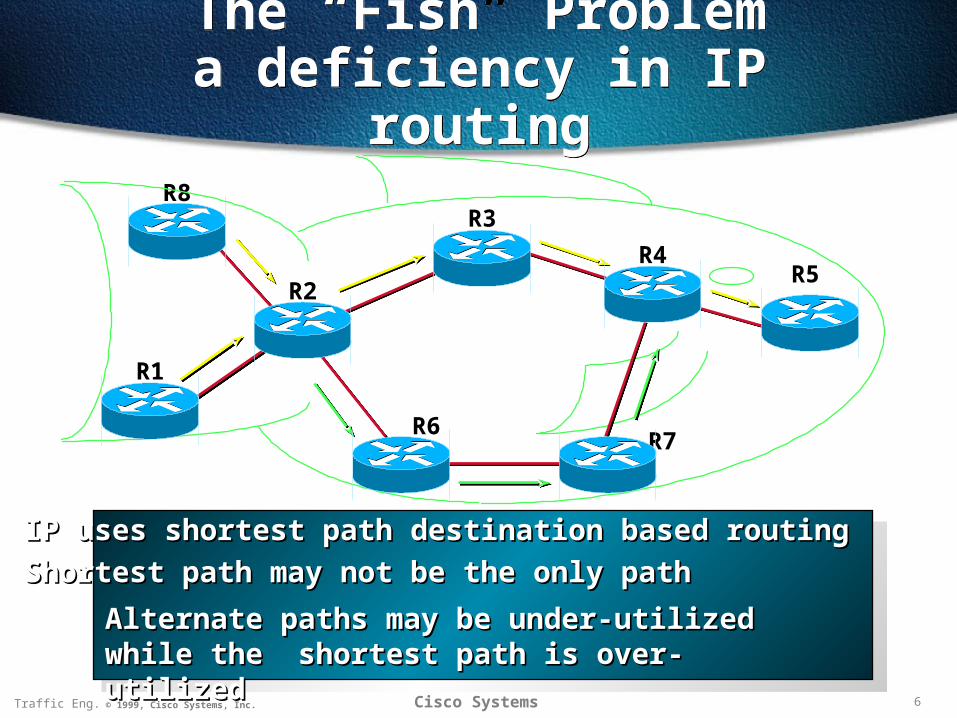
The “Fish” Problema deficiency in IP routing
The “Fish” Problema deficiency in IP routing
IP uses shortest path destination based routingIP uses shortest path destination based routing
Shortest path may not be the only pathShortest path may not be the only path
Alternate paths may be under-utilized while the Alternate paths may be under-utilized while the shortest path is over-utilizedshortest path is over-utilized
R8
R2
R6
R3
R4
R7
R5
R1
7Traffic Eng. © 1999, Cisco Systems, Inc. Cisco Systems
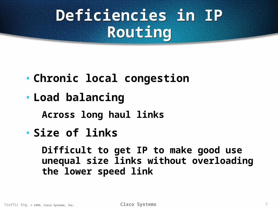
Deficiencies in IP RoutingDeficiencies in IP Routing
• Chronic local congestion
• Load balancing
Across long haul links
• Size of links
Difficult to get IP to make good use unequal size links without overloading the lower speed link
8Traffic Eng. © 1999, Cisco Systems, Inc. Cisco Systems
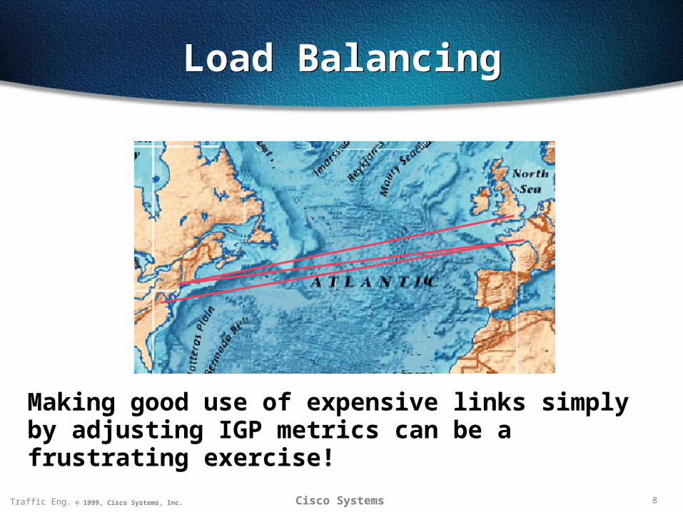
Load BalancingLoad Balancing
Making good use of expensive links simply by adjusting IGP metrics can be a frustrating exercise!
9Traffic Eng. © 1999, Cisco Systems, Inc. Cisco Systems
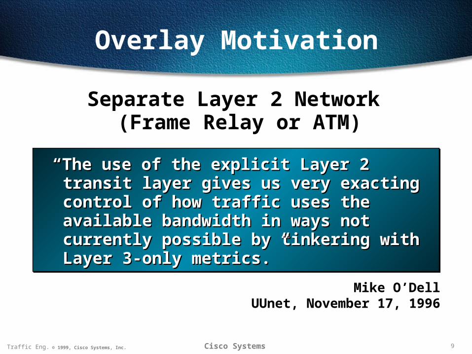
Overlay Motivation
Separate Layer 2 Network (Frame Relay or ATM)
Mike O’DellUUnet, November 17, 1996
““The use of the explicit Layer 2 transit layer The use of the explicit Layer 2 transit layer gives us very exacting control of how gives us very exacting control of how traffic uses the available bandwidth in traffic uses the available bandwidth in ways not currently possible by tinkering ways not currently possible by tinkering with Layer 3-only metrics.”with Layer 3-only metrics.”
10Traffic Eng. © 1999, Cisco Systems, Inc. Cisco Systems
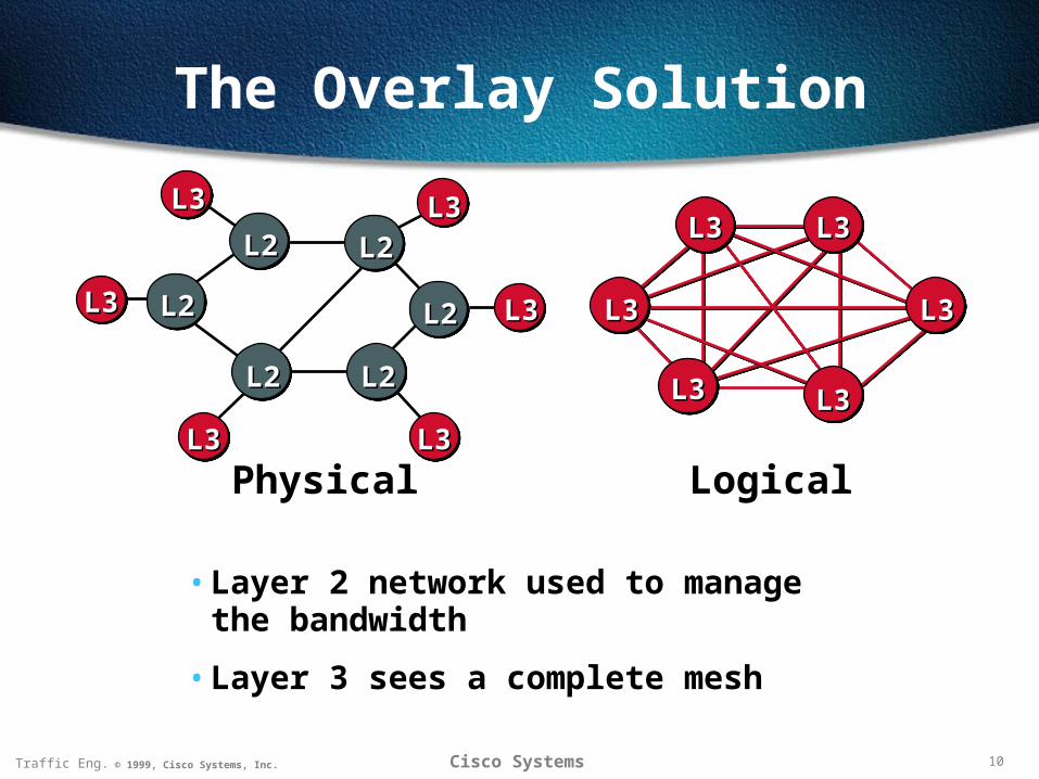
The Overlay Solution
• Layer 2 network used to manage the bandwidth
• Layer 3 sees a complete mesh
L3L3
L3L3
L3L3
L3L3
L3L3
L3L3
L3L3
L2L2
L2L2
L2L2
L2L2
L2L2
L2L2
L3L3
L3L3
L3L3
L3L3 L3L3
Physical Logical
11Traffic Eng. © 1999, Cisco Systems, Inc. Cisco Systems
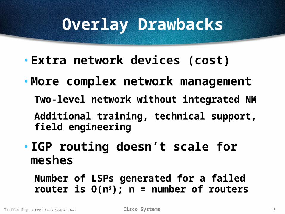
Overlay Drawbacks
• Extra network devices (cost)
• More complex network management
Two-level network without integrated NM
Additional training, technical support, field engineering
• IGP routing doesn’t scale for meshes
Number of LSPs generated for a failed router is O(n3); n = number of routers
12Traffic Eng. © 1999, Cisco Systems, Inc. Cisco Systems
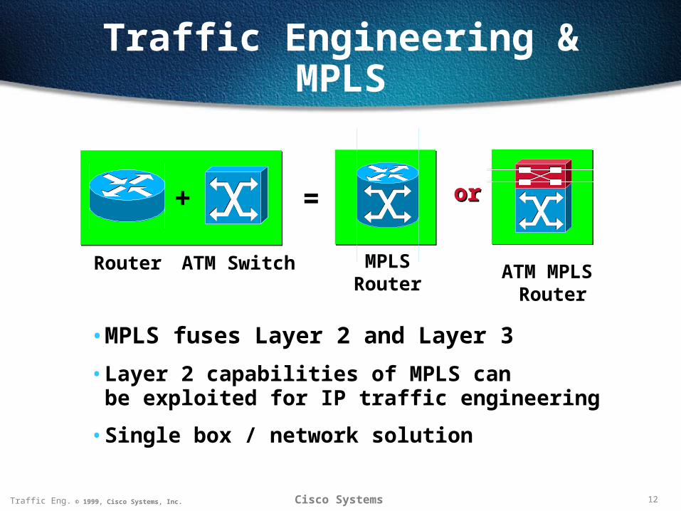
Traffic Engineering & MPLS
• MPLS fuses Layer 2 and Layer 3
• Layer 2 capabilities of MPLS canbe exploited for IP traffic engineering
• Single box / network solution
+ oror=
Router ATM Switch MPLS Router
ATM MPLS Router
13Traffic Eng. © 1999, Cisco Systems, Inc. Cisco Systems
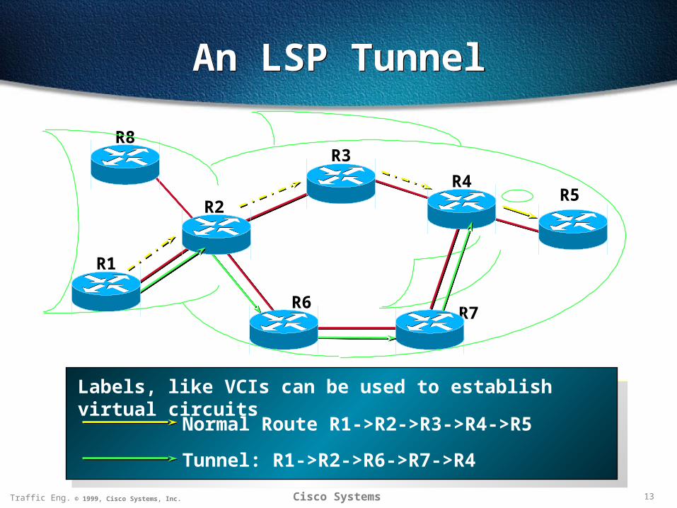
An LSP TunnelAn LSP Tunnel
R8
R2
R6
R3
R4
R7
R5
R1
Normal Route R1->R2->R3->R4->R5
Tunnel: R1->R2->R6->R7->R4
Labels, like VCIs can be used to establish virtual circuits
14Traffic Eng. © 1999, Cisco Systems, Inc. Cisco Systems
Comprehensive Traffic Engineering
Comprehensive Traffic Engineering
• Network design
Engineer the topology to fit the traffic
• Traffic engineering
Engineer the traffic to fit the topology
Given a fixedfixed topology and a traffic matrix, traffic matrix, what set of explicit routes offers the best overall network performance?
15Traffic Eng. © 1999, Cisco Systems, Inc. Cisco Systems
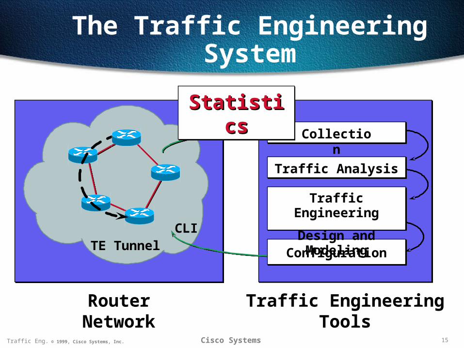
The Traffic Engineering System
TE TunnelCLI
Router Network Traffic Engineering Tools
Configuration
Collection
Traffic Analysis
Traffic Engineering
Design and Modeling
StatisticsStatisticsStatisticsStatistics
16Traffic Eng. © 1999, Cisco Systems, Inc. Cisco Systems
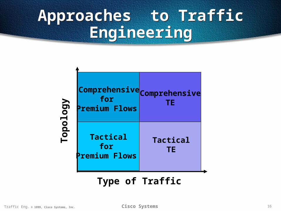
Approaches to TrafficEngineering
Approaches to TrafficEngineering
To
po
log
y
Type of Traffic
ComprehensiveTE
Comprehensivefor
Premium Flows
Tacticalfor
Premium Flows
TacticalTE
17Traffic Eng. © 1999, Cisco Systems, Inc. Cisco Systems
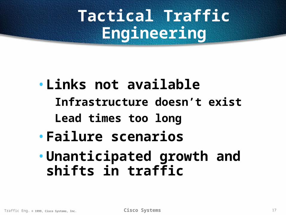
Tactical Traffic Engineering
• Links not availableInfrastructure doesn’t exist
Lead times too long
• Failure scenarios
• Unanticipated growth and shifts in traffic
18Traffic Eng. © 1999, Cisco Systems, Inc. Cisco Systems
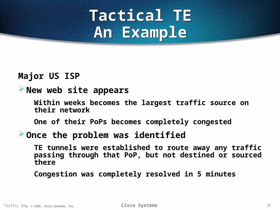
Tactical TEAn ExampleTactical TEAn Example
Major US ISP
New web site appears
Within weeks becomes the largest traffic source on their network
One of their PoPs becomes completely congested
Once the problem was identified
TE tunnels were established to route away any traffic passing through that PoP, but not destined or sourced there
Congestion was completely resolved in 5 minutes
19Traffic Eng. © 1999, Cisco Systems, Inc. Cisco Systems
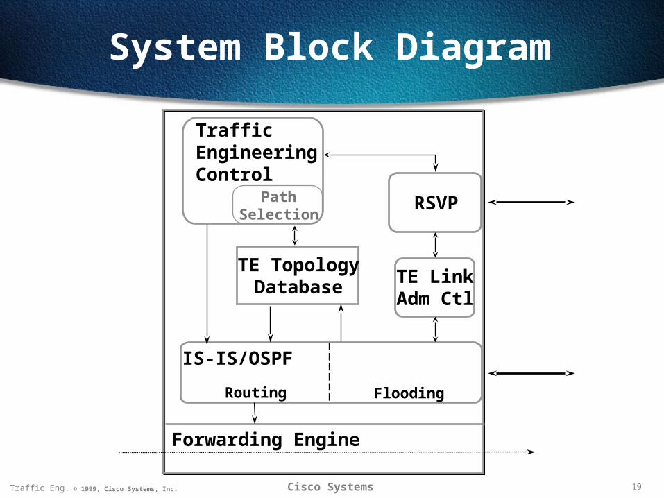
System Block Diagram
TrafficEngineering Control
PathSelection
TE TopologyDatabase
RSVP
FloodingRouting
IS-IS/OSPF
TE LinkAdm Ctl
Forwarding Engine
20Traffic Eng. © 1999, Cisco Systems, Inc. Cisco Systems
TE Tunnel AttributesTE Tunnel Attributes
• Bandwidth
• Setup & Holding priorities
Used for Admission Control
• Resource class affinity
Simple policy routing
• Path Options
Input to route selection
21Traffic Eng. © 1999, Cisco Systems, Inc. Cisco Systems
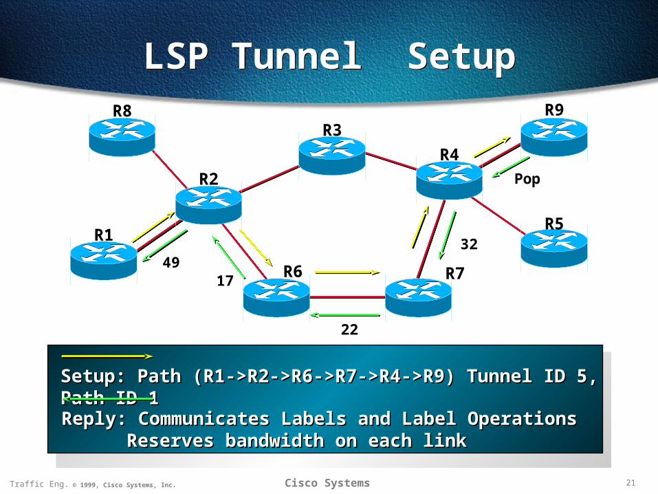
LSP Tunnel SetupLSP Tunnel Setup
Setup: Path (R1->R2->R6->R7->R4->R9) Tunnel ID 5, Path ID 1Setup: Path (R1->R2->R6->R7->R4->R9) Tunnel ID 5, Path ID 1
22
4917
R8
R2
R6
R3
R4
R7
R1R5
R9
Reply: Communicates Labels and Label OperationsReply: Communicates Labels and Label OperationsReserves bandwidth on each linkReserves bandwidth on each link
Pop
32
22Traffic Eng. © 1999, Cisco Systems, Inc. Cisco Systems
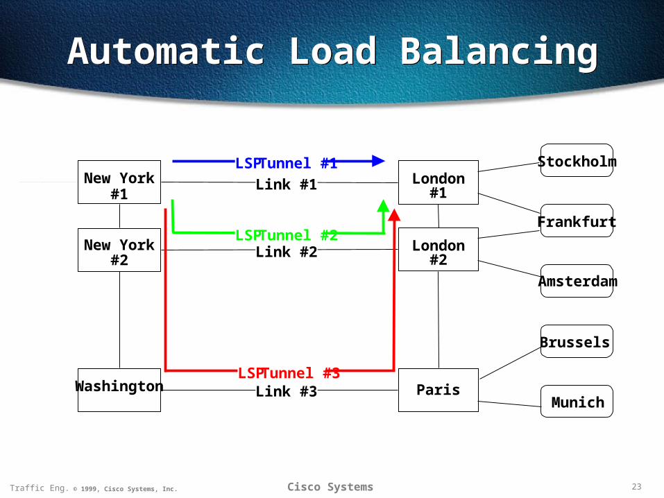
Multiple Parallel Tunnels
• Automatically load shared
• Weighted by bandwidth
to nearest part in 16
• Traffic assigned by either
Source-Destination hash
Round robin
23Traffic Eng. © 1999, Cisco Systems, Inc. Cisco Systems
Automatic Load BalancingAutomatic Load Balancing
New York#1
New York#2
Washington
London#1
London#2
Paris
Stockholm
Munich
Brussels
Frankfurt
Amsterdam
Link #1
Link #2
Link #3
LSP Tunnel #1
LSP Tunnel #2
LSP Tunnel #3
24Traffic Eng. © 1999, Cisco Systems, Inc. Cisco Systems
Additional FeaturesAdditional Features
• Adjusting to failures
Requires rapid notification
• Adjusting to improvements
• Need to account for
Global optimality
Network stability
25Traffic Eng. © 1999, Cisco Systems, Inc. Cisco Systems
Protection StrategyProtection Strategy
Two pronged approach:
• Local protectionRepair made at the point of failure us to keep critical applications going
Fast - O(milliseconds)
Sub-optimal
• Path protectionAn optimized long term repair
Slower - O(seconds)
26Traffic Eng. © 1999, Cisco Systems, Inc. Cisco Systems
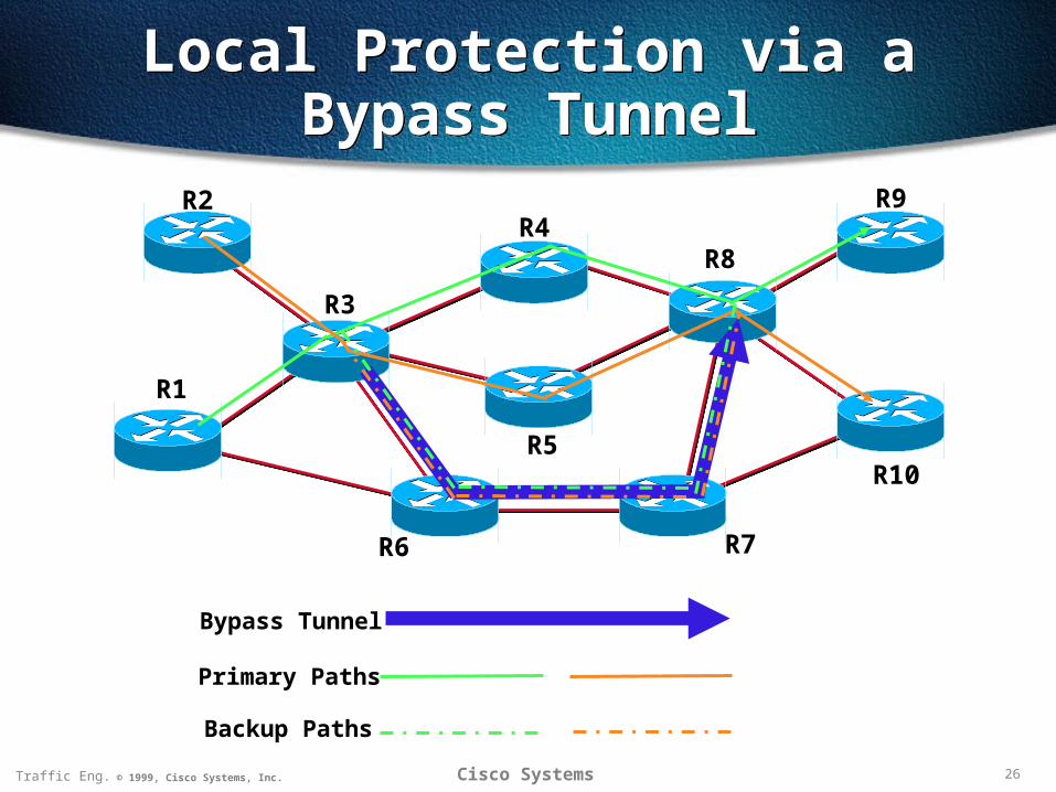
Local Protection via aBypass Tunnel
Local Protection via aBypass Tunnel
R2
R3
R6
R4R8
R7
R1
R10
R9
R5
Primary Paths
Bypass Tunnel
Backup Paths
27Traffic Eng. © 1999, Cisco Systems, Inc. Cisco Systems
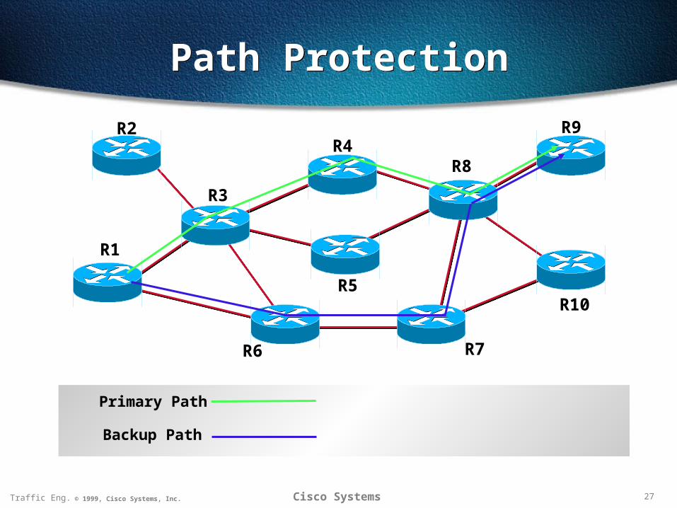
Path ProtectionPath Protection
R2
R3
R6
R4R8
R7
R1
R10
R9
R5
Primary Path
Backup Path
28Traffic Eng. © 1999, Cisco Systems, Inc. Cisco Systems
SummarySummary
Traffic engineering provides the means to
Save transmission costs
Address routing deficiencies
Attack tactical network engineering problems
Provide better QoS
Making sure resource are available
Minimizing disruption

29Traffic Engineering © 1999, Cisco Systems, Inc.
Thank You
Thank You