Embed Size (px)
Citation preview

1 Introduction
A standard voltage and current generator is a signal source that can precisely generate the desired DC or AC voltage and current for use in calibrating voltage and cur-rent meters called “testers” and “multi-meters.” The fre-quencies of AC voltage and current include 50 Hz and 60 Hz, which are commercial power supply frequencies and 400 Hz for use in passenger aircraft.
The Radio Law requires the use of a calibrated voltam-meter when testing wireless equipment. NICT provides calibration services for radio frequency measurement in-struments, such as high frequency power meters, attenua-tors, and antennas. NICT also provides calibration services for DC/low frequency measurement devices that are volt-ammeters and standard voltage and current generators, as some of the devices for testing wireless equipment.
As a laboratory accredited under the Japan Calibration Service System (JSCC), NICT has also provided calibration services that satisfy the ISO/IEC17025 standard, for stan-dard voltage and current generators, since 2006.
This paper describes the calibration of voltage and current of DC/low frequency ranges, while showing actual calibration procedures. It also describes how to estimate uncertainty associated with calibration results.
2 Definitions
The calibration of the voltage and current of a standard voltage and current generator is carried out for the purpose of ascertaining the open-circuit voltage and short-circuit current at the output terminal pair shown in Fig. 1 (b), for
the voltage value and current value set in a standard volt-age and current generator shown in Fig. 1 (a). In practice,
(b)
Fig.F 1 Standard voltage and current generator and calibration reference plane
(a)
Open-circuit voltage or short- circuit current generated between terminals
2-3 Calibration of Standard Voltage and Current Generator
Katsumi FUJII, Kojiro SAKAI, Tsutomu SUGIYAMA, Kouichi SEBATA, and Iwao NISHIYAMA
This paper describes the calibration method of standard voltage and current generators that provide a reference voltage/current in order to calibrate testers (analogue multi-meters) and digital multi-meters (DMM). A Standard voltage/current generator can generate very precise DC voltage, DC current, AC Voltage, or AC current. Since the frequency range of the output signal of such a generator is from DC up to 400 Hz, it is necessary to perform the measurement operation with special care that is different from that in an RF band. In this paper, the calibration procedure of the generator and evaluation of the calibration uncertainties are described.
Title:J2016E-02-03.indd p45 2017/03/01/ 水 10:24:49
45
2 Research and Development of Calibration Technology

as shown in Fig. 2, calibration is done by connecting a digital multi-meter and taking measurements.
3 Calibration method
The calibration of a standard voltage and current gen-erator, as shown in Fig. 2, is performed by the substitution method, which uses a digital multi-meter (hereinafter,
“DMM”) to measure and compare output from a reference standard device maintained and managed by NICT (here-inafter, “standard device”), and output from a standard voltage and current generator being calibrated (hereinafter, “device under test”) [1]. The DMM used for the comparison must be sufficiently precise to enable the discovery of dif-ferences between the voltage and current generated from a standard voltage and current generator, and must have linearity in the range of those differences. Also, voltage measurement terminals must have sufficiently large internal resistance, and current measurement terminals must have sufficiently small internal resistance. One must also be careful about the material quality and length of the cables that connect the standard voltage and current generator to the DMM. The effects of these are assessed as sources of uncertainty of calibration results, as described later.
The specific procedures are as follows. Figure 3 shows an outline of the procedures.
(1) Connect the device under test to the DMM, set the indicated value of the device under test to the nominal value VNOMINAL, and read the VDUT value displayed on the DMM when output.
(2) Connect the standard device to the DMM, set the indicated value of the standard device to the nominal
Fig.F 3 Calibration procedure
1.000 005 V
1.000 000 V1.000 000 V
DUT
1.000 013 V
DMMDMM
VSTDVDUT
VNOMINAL VNOMINAL
STD
Calibration value CDUT
DUTSTDSTDDUT VVCC
Step (1) Step (2)
1.000 002 V
= 1.000 002 V –1.000 005 V +1.000 013 V= 1.000 010 V
Reference planeReference planeCalibration value CSTD
Fig.F 2 Calibration of standard voltage and current generator(Top) Multi-meter: Fluke 8508A, (Middle) Amplifier: Fluke 5725A(Bottom) Standard voltage and current generator: Fluke 5720A
46 Journal of the National Institute of Information and Communications Technology Vol. 63 No. 1 (2016)
Title:J2016E-02-03.indd p46 2017/03/01/ 水 10:24:49
2 Research and Development of Calibration Technology

value VNOMINAL, and read the VSTD value displayed on the DMM when output.
(3) Use the following equation to determine the cali-bration value CDUT for the indicated value VNOMINAL of the device under test. (For derivation of the equation, see the Appendix.)
DUTSTDSTDDUT VVCC
(1)
Here, CSTD is the calibration value for the indicated value VNOMINAL, obtained when the upper-level calibration organization calibrated the standard device.
In actual calibration work, values measured multiple times by a DMM are read on a PC connected to the DMM, and the average value and experimental standard deviation are recorded.
Also, for the calibration value CSTD of the standard device, the value calibrated at the superior calibration or-ganization is used. NICT ensures traceability to the na-tional standard by the traceability system shown in Fig. 4.
4 Calibration results
4.1 Standard device and DMMTable 1 shows voltage and current calibration performed
by NICT as a JCSS-accredited laboratory. For the standard device, a Fluke 5720A Multifunction Calibrator is used. Within the calibration range shown in Table 1, for 10 A DC current and 10 A AC current, a dedicated Fluke 5725A Amplifier is used to generate current. Japan Electric Meters Inspection Corporation (JEMIC) performs calibrations for these once per year, and obtains the calibration value CSTD. On the other hand, the Fluke 8508A Reference Multimeter is used as the DMM to compare outputs of the standard device vs. the device under test (Fig. 2).
4.2 Connection methodWhen connecting a standard voltage and current gen-
erator to a DMM, ground one of the measurement termi-nals to enable stable measurements. As shown in Fig. 1 (b), the standard device 5720A has output terminals (Hi, Lo), guard terminal and ground terminal. Also, the DMM 8508A has an input terminal and a guard terminal. The
TableT 1 Calibration items at NICT
Item Frequency Voltage, Current
DC voltage DC 1 V, 10 V, 100 V
DC current DC 10 mA, 100 mA, 1 A, 10 A
AC voltage 50 Hz, 60 Hz, 400 Hz 10 V, 100 V
AC current 50 Hz, 60 Hz 100 mA, 1 A, 10 A
Fig.F 4 Traceability chart
National Institute of Advanced Industrial Science and Technology (AIST)
National Metrology Institute of Japan (NMIJ)
Josephson effect (Voltage measurement device) Quantum hall effect (Resistance measurement device) AC/DC current converter for AC voltageAC/DC difference measuring device
Japan Electric Meters Inspection Corporation (JEMIC)
Voltage generator, Standard voltage divider, Standard resistor, Standard current divider, AC/DC comparator, AC voltage measuring device
Secondary standardReference standard
Primary standard
NICTStandard voltage and current generator, Amplifier
Customer
Standard voltage and current generator
Referencestandard
OFF
DMM
Guard Guard
Chassis Chassis
Hi
Lo
Hi
Lo
Ground
Guard
DMM
Guard Guard
Chassis Chassis
Hi
Lo
Guard
Hi
Lo
Ground
Guard
Guard
ExGrd ExGrd
ExGrd ExGrd
ONOFF
ONOFF
ON
ONOFF
STD
STD
Fig.F 5 Shielding and grounding
Title:J2016E-02-03.indd p47 2017/03/01/ 水 10:24:49
47
2-3 CalibCalion iof aConnCbn iaaCage Conn Cbbgeona geongebCaib

standard voltage and current generator and DMM are con-nected by two lead wires shielded by wire mesh, and the wire mesh part is connected to both guard terminals. That is, the standard voltage and current generator and DMM are measured inside the metal shielding called “guards,” represented by the dashed lines in Fig. 5 [2][3].
Here, stable measurements are achieved by conducting between the Lo terminal and guard terminal. The standard
device and DMM have a button labeled [Ex Grd] (External Guard), which turns on/off the conduction between the Lo terminal and guard in the unit. If this button is on, it cuts the conduction between the Lo terminal and guard. When it is off, there is conduction between the Lo terminal and
OFF
DMM
Lo
Hi
Ground
GuardExGrd[OFF]
ExGrd[ON]
ON
OFF
DMM
Lo
Hi
Ground
GuardExGrd[OFF]
ExGrd[OFF]
OFF
STD
STD
(b)
Fig.F 7 Generation of unwanted current pathway
(a)
1.000 005 V
1.000 000 V
DMM
ExGrd [OFF]
DUT(No guard terminal)
1.000 000 V
STDExGrd [OFF]
1.002 V
DMM(No guard terminal)
10.000 00 A
STD10.000 11 A
DMM
Amp.
(a) (b)
Fig.F 6 Short-circuit plate
(c)
Fig.F 8 External guard settings example(a) If calibrating a standard device that has no guard terminal, (b) If calibrating a DMM that has no guard terminal, (c) If using an amplifier
48 Journal of the National Institute of Information and Communications Technology Vol. 63 No. 1 (2016)
Title:J2016E-02-03.indd p48 2017/03/01/ 水 10:24:49
2 Research and Development of Calibration Technology
guard. Moreover, as shown in Fig. 6, the standard device has a short plate (short circuit plate) for conductivity be-tween the external guard terminal and ground terminal. The ground terminal conducts with the case. The short plate can be removed.
Here, as shown in Fig. 7 (a), the guard must be con-
nected with only one Lo terminal on either the standard device or DMM. This is a method called “Single-point earth.” If as shown in Fig. 7 (b), the guard conducts with the Lo terminals on both standard device and DMM, then unwanted current flows via the guard, so correct measure-ments cannot be taken.
(a) (b)
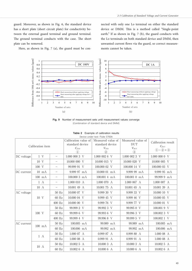
Fig.F 9 Number of measurement sets until measurement values converge(Combination of standard device and DMM)
TableT 2 Example of calibration resultsDevice under test: Fluke 5700A
Calibration item
Calibration value of standard device
CSTD
①
Measured value of standard device
VSTD
②
Measured value of DUTVDUT
③
Calibration resultCDUT
①-②+③
DC voltage 1 V - 1.000 000 3 V 1.000 002 6 V 1.000 002 3 V 1.000 000 0 V10 V - 10.000 000 V 10.000 015 V 10.000 020 V 10.000 005 V
100 V - 99.999 91 V 100.000 02 V 100.000 14 V 100.000 03 VDC current 10 mA - 9.999 97 mA 10.000 01 mA 9.999 99 mA 9.999 95 mA
100 mA - 100.000 3 mA 100.001 4 mA 100.001 0 mA 99.999 9 mA1 A - 1.000 010 A 1.000 070 A 1.000 067 A 1.000 007 A
10 A - 10.001 49 A 10.001 75 A 10.001 65 A 10.001 39 AAC voltage
10 V50 Hz 10.000 07 V 9.999 30 V 9.999 33 V 10.000 10 V60 Hz 10.000 04 V 9.999 45 V 9.999 46 V 10.000 05 V
400 Hz 10.000 00 V 9.999 76 V 9.999 77 V 10.000 01 V
100 V50 Hz 99.999 2 V 99.992 3 V 99.995 0 V 100.001 9 V60 Hz 99.999 6 V 99.993 6 V 99.996 3 V 100.002 3 V
400 Hz 99.999 4 V 99.996 8 V 99.999 5 V 100.002 1 VAC current
100 mA50 Hz 100.005 mA 99.989 mA 99.989 mA 100.005 mA60 Hz 100.006 mA 99.992 mA 99.992 mA 100.006 mA
1 A50 Hz 1.000 07 A 0.999 87 A 0.999 88 A 1.000 08 A60 Hz 1.000 08 A 0.999 91 A 0.999 91 A 1.000 08 A
10 A50 Hz 10.002 5 A 10.000 3 A 10.000 3 A 10.002 5 A60 Hz 10.002 6 A 10.000 6 A 10.000 6 A 10.002 6 A
1 100.8 DC 100V 8 DC 1A0.6 60.4 40.2 2
0 0-0.2 -2-0.4 -4-0.6 Start measuring without applying voltage -6 Start measuring without applying voltage
Start measuring after applying voltage for 5 Start measuring after applying voltage -0.8 min. -8 for 5 min.
-1 -101 2 3 4 5 6 7 8 9 10 1 2 3 4 5 6 7 8 9 10
Number of sets
Diff
eren
ce fr
om 1
0th
set’s
mea
s. v
alue
s [p
pm]
Diff
eren
ce fr
om 1
0th
set’s
mea
s. v
alue
s [p
pm]
Number of sets
Title:J2016E-02-03.indd p49 2017/03/01/ 水 10:24:49
49
2-3 CalibCalion iof aConnCbn iaaCage Conn Cbbgeona geongebCaib

The device under test determines whether grounding is performed on the standard voltage and current generator side, or on the DMM side. As a reference, Fig. 8 (a) shows a wiring diagram used if calibrating a standard voltage and current generator that does not have a guard terminal, whereas Fig. 8 (b) shows a wiring diagram if calibrating a DMM or tester that does not have a guard terminal. Moreover, if an amplifier is used, the amplifier does not have a guard terminal, so as shown in Fig. 8 (c), the in-struction manual [3] recommends that 2 lead lines connect the amplifier to the DMM, but magnetic fields arriving from outside are captured in the loop created by the 2 lead lines and devices, so it is recommended to twist the 2 lead lines to prevent bad effects on measurement results. As described above, depending on the device under test, consider the grounding method, then perform measure-ments.
4.3 Necessity of applying a current before measuring
To achieve stable measurements, we studied the neces-sity of applying a voltage or current to the DMM before starting measurements. The two graphs in Fig. 9 show re-sults when we connected the standard device and DMM, and applied DC 100 V or DC 1 A. The measurements were done 100 times as 1 set, with a 1 minute rest period between sets; we measured 10 sets. The graph’s vertical axis shows deviations of measurement values from sets 1 to 9, when the 10th set’s measurement results are a reference (unit is ppm).
In the figure, the red ○ and lines show the results of 10 sets of measurements when the first measurements are started after letting the devices reach room temperature (23 °C±2 °C). The blue ▲ and lines show the results of 10 sets of measurements performed by activating the standard device and DMM and applying a voltage or current for 5 minutes, before starting the first set of measurements.
In Figure 9 (b), looking at the graph’s red ○ and line, multiple sets of measurements are required until the mea-surement values converge to a certain value. Looking at the graph’s blue ▲ and line, a current was continually applied for 5 minutes, which made the measurement values con-verge earlier. On the other hand, in the case of voltage measurements shown in Fig. 9 (a), we see there is sufficient convergence. From these results, it seems that DC measure-ments take time to converge on a certain value because during current measurements, a resistance temperature rise in the DMM causes change in the value of resistance. When
measuring a large current, more heat is generated from resistance in the DMM, so special care is needed.
4.4 Calibration resultsWe show the results of calibrating a Fluke 5700A
Multifunction Calibrator as the device under test. Similar to the standard device, the 5700A has a guard terminal and ground terminal, but we performed calibration with a short circuit plate connected between both terminals, assuming that the customer requests such a condition for calibration.
In this case, the Lo terminal and guard terminal are connected on the device under test and standard device, so one must cut the connection between the guard and ground on the DMM side. Therefore, we turned ON the DMM’s [Ex Grd] button, then performed measurements. Table 2 shows the calibration results. The number of digits of calibration results depends on the uncertainty described below: DC voltage 7 digits, DC current 6 digits, AC voltage 6 digits, AC current 5 digits. If DC or AC 10 A current using an amplifier, then there is large uncertainty of output from the amplifier, so even if displayed on the DMM, the number of digits decreases for final results.
5 Uncertainty
Uncertainty associated with calibration results is dis-played as expanded uncertainty estimated to have an ap-proximately 95 % confidence level. The size of that value which occurs due to multiple sources as described below can be estimated by using the following equation to com-pose it [1][4].
22DUT
2STD
2STDDUT sVuVuCuCu
(2)
Here,
DUTCu
: Uncertainty of device under test.
STDCu
: Uncertainty of standard device.
STDVu
: Uncertainty of the measurement value displayed on the DMM, when the indicated value of the standard device is aligned with VNOMINAL, and voltage and current are output.
DUTVu
: Uncertainty of the measurement value displayed on the DMM, when the indicated value of the device under test is aligned with VNOMINAL, and voltage and current are output.
s : Variability of calibration results.
Each item is explained below.
50 Journal of the National Institute of Information and Communications Technology Vol. 63 No. 1 (2016)
Title:J2016E-02-03.indd p50 2017/03/01/ 水 10:24:49
2 Research and Development of Calibration Technology

5.1 : Uncertainty of standard device.5.1.1 Uncertainty of calibration at a superior calibration
organizationAs shown in Fig. 4, the standard devices maintained
and managed by NICT are calibrated by the Japan Electric Meters Inspection Corporation (JEMIC). NICT calibrates with reference to the calibration values and uncertainty written in the calibration certificates issued by JEMIC.
It is written in a calibration certificate that the ex-panded uncertainty reported in the calibration certificate is stated as the standard uncertainty multiplied by a cover-age factor k=2, providing a level of confidence of approxi-mately 95 %. Therefore, standard uncertainty is the value of uncertainty written in the calibration certificate, divided by the coverage factor k=2.5.1.2 Performance of standard device
Calibration of a standard device is done once per year, but its characteristics can change while that year passes. The degree of that change over time is written as uncer-tainty in the instruction manual, and as long as it is not damaged, the change in output over the year falls within the range of that uncertainty. In other words, this shows that even if not damaged, output can change within the range of that uncertainty. In the extended specification document of the Fluke 5720A standard device, uncertainty in 1 year is written as a value with a 99 % confidence level, so divide it by the coverage factor k=2.576 to obtain the standard uncertainty.
5.2
STDVu
: Uncertainty of measurement results of standard device
When the standard device is connected to a DMM and measured, the VSTD value obtained can be considered to have uncertainty that depends on the following sources.5.2.1 Performance of DMM
For uncertainty of performance of the DMM that measures voltage and current output from the standard device or device under test, the linearity and degree of stability etc. of the measurement device are expected to affect calibration results. However, since it takes little time to perform measurements by replacing the standard device with the device under test, the DMM can be considered to be sufficiently stable, and tiny differences in output from the standard device or device under test near the indicated value VNOMINAL are measured within a range where the linearity of DMM is sufficiently sustained, so uncertainty caused by the DMM’s performance is assumed to be 0. Fluctuations of measured values during the measurement
period are included in “variability” described later.5.2.2 Resolution of digital indication of DMM
One cannot know the values of digits beyond the minimum number of digits displayed on the DMM, so they are considered uncertain. Now, considering when the measurement result is displayed as 0.98 V, then as shown in Fig. 10, if values were measured in the range from 0.975 to 0.985 V (0.98 V ± 0.005 V), all are displayed as 0.98 V. That is, values of the third and digits further below the decimal point are uncertain, and the true measured value could exist anywhere, so the probability density distribu-tion is considered uniform, and the standard uncertainty is obtained. In the case of the above example, standard uncertainty is 0.0029 V (= 0.005 /√3 V).5.2.3 Effects of thermoelectromotive force (Only when
measuring DC voltage)A cable is used to connect the DMM to the standard
voltage and current generator, but when terminals of dif-ferent metals are connected, and there are temperature differences between the 4 terminals, we see that thermo-electromotive force occurs due to the Seebeck effect [5]. This phenomenon is not a problem when measuring DC current, AC voltage or AC current, but it becomes a prob-lem when calibrating DC voltage. It especially cannot be ignored when measuring small DC voltages of 1V or less.
When measuring DC voltage, one must not only pay attention to the surrounding temperature; it is also neces-sary to measure the terminal temperatures while the DMM and standard voltage and current generator are connected by a lead line, and make sure that those differences are within ± 1.5 ºC. As conditions for measuring the size of standard uncertainty, connection points of the standard device and test lead are made of tellurium copper, and we see from the product specifications [6] that the thermo-electromotive force coefficient is 1.3 μV/ºC or less. Now, if one performs measurement after checking that the tem-perature differences are within ± 1.5 ºC, then the standard uncertainty of temperature is a uniform distribution with
STDCu
Fig.F 10 Uncertainty of resolution of digital indication
Range where displayed as 0.98
0.990.97
0.975 0.985
Measured value
0.98
Title:J2016E-02-03.indd p51 2017/03/01/ 水 10:24:49
51
2-3 CalibCalion iof aConnCbn iaaCage Conn Cbbgeona geongebCaib
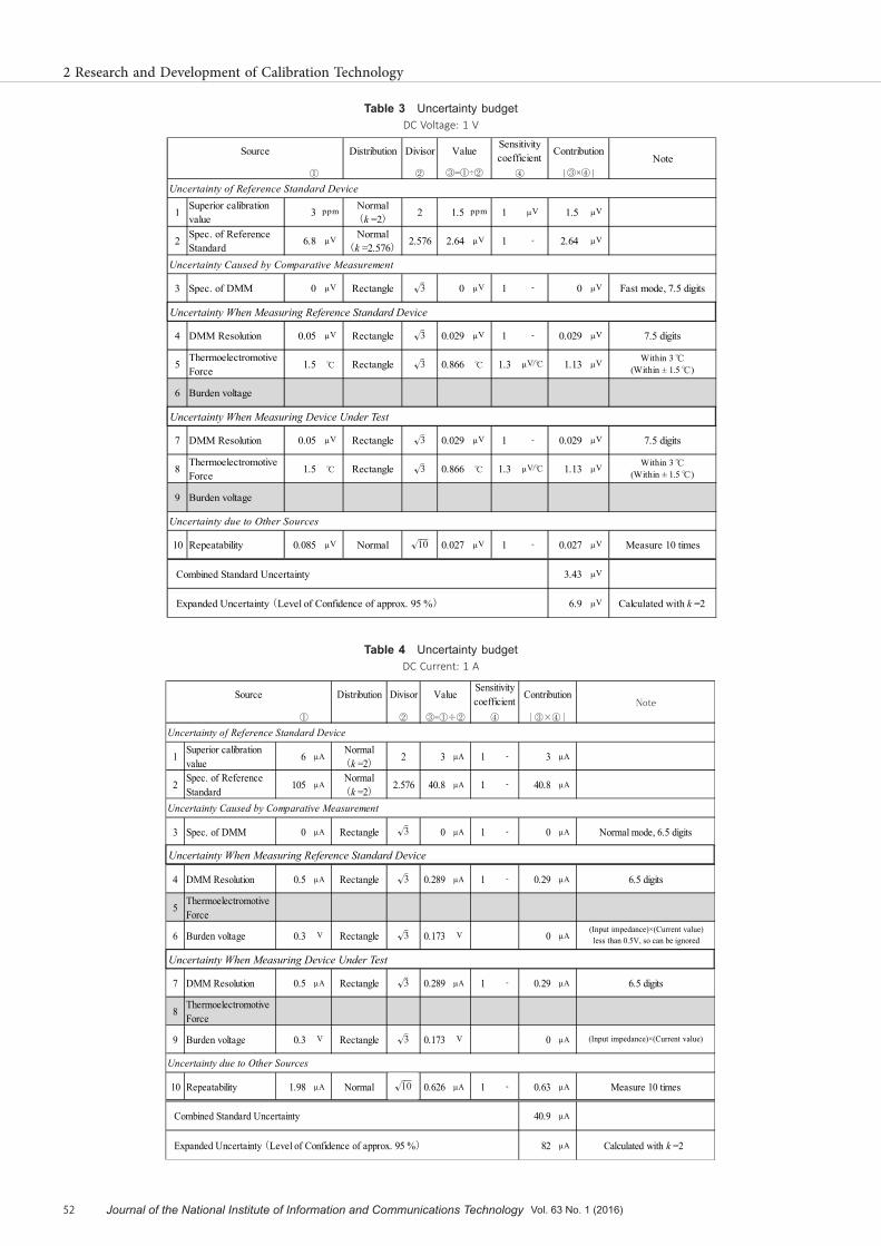
TableT 4 Uncertainty budgetDC Current: 1 A
Distribution Divisor
②
Uncertainty of Reference Standard Device
1 Superior calibrationvalue 6
Normal(k =2)
2 3 1 - 3
2 Spec. of ReferenceStandard 105
Normal(k =2)
2.576 40.8 1 - 40.8
Uncertainty Caused by Comparative Measurement
3 Spec. of DMM 0 Rectangle √3 0 1 - 0 Normal mode, 6.5 digits
Uncertainty When Measure Reference Standard Device
4 DMM Resolution 0.5 Rectangle √3 0.289 1 - 0.29 6.5 digits
5 ThermoelectromotiveForce
6 Burden voltage 0.3 V Rectangle √3 0.173 V 0 (Input impedance)×(Current value) less than 0.5V, so can be ignored
Uncertainty When Measure Device Under Test
7 DMM Resolution 0.5 Rectangle √3 0.289 1 - 0.29 6.5 digits
8 ThermoelectromotiveForce
9 Burden voltage 0.3 V Rectangle √3 0.173 V 0 (Input impedance)×(Current value)
Uncertainty due to Other Sources
10 Repeatability 1.98 Normal √10 0.626 1 - 0.63 Measure 10 times
Combined Standard Uncertainty 40.9
Expanded Uncertainty (Level of Confidence of approx. 95 %) 82 Calculated with k =2
Note
④ | ③×④ |
Source
③=①÷②
Value Sensitivitycoefficient Contribution
①
Uncertainty When Measuring Device Under Test
Uncertainty When Measuring Reference Standard Device
TableT 3 Uncertainty budgetDC Voltage: 1 V
Distribution Divisor
②
Uncertainty of Reference Standard Device
1 Superior calibrationvalue 3 ppm Normal
(k =2) 2 1.5 ppm 1 V 1.5 V
2 Spec. of ReferenceStandard 6.8 V Normal
(k =2.576) 2.576 2.64 V 1 - 2.64 V
Uncertainty Caused by Comparative Measurement
3 Spec. of DMM 0 V Rectangle √3 0 V 1 - 0 V Fast mode, 7.5 digits
Uncertainty When Measure Reference Standard Device
4 DMM Resolution 0.05 V Rectangle √3 0.029 V 1 - 0.029 V 7.5 digits
5 ThermoelectromotiveForce 1.5 ℃ Rectangle √3 0.866 ℃ 1.3 V/℃ 1.13 V Within 3 ℃
(Within ± 1.5 ℃)
6 Burden voltage
Uncertainty When Measure Device Under Test
7 DMM Resolution 0.05 V Rectangle √3 0.029 V 1 - 0.029 V 7.5 digits
8 ThermoelectromotiveForce 1.5 ℃ Rectangle √3 0.866 ℃ 1.3 V/℃ 1.13 V Within 3 ℃
(Within ± 1.5 ℃)
9 Burden voltage
Uncertainty due to Other Sources
10 Repeatability 0.085 V Normal √10 0.027 V 1 - 0.027 V Measure 10 times
Combined Standard Uncertainty 3.43 V
Expanded Uncertainty (Level of Confidence of approx. 95 %) 6.9 V Calculated with k =2
Sensitivitycoefficient Contribution
Note① ③=①÷② ④ | ③×④ |
Source Value
Uncertainty When Measuring Device Under Test
Uncertainty When Measuring Reference Standard Device
√3
√3
√3
√3
√3
√10
√3
√10
√3
√3
√3
√3
52 Journal of the National Institute of Information and Communications Technology Vol. 63 No. 1 (2016)
Title:J2016E-02-03.indd p52 2017/03/01/ 水 10:24:49
2 Research and Development of Calibration Technology

± 1.5 ºC as its limit, which is 0.866 ºC (= 1.5 / √3 ºC), and using the thermoelectromotive force coefficient to convert this value into electromotive force, we obtain 1.13 μV (0.866 ºC × 1.3 μV/ºC). That is, when measured while differences in terminal voltages are within ± 1.5 ºC, stan-dard uncertainty caused by electromotive force is 1.13 μV.
One can consider the same way if a device under test is connected to the DMM. But one must investigate the metals of the terminals of the device under test, and the thermoelectromotive force coefficients of those metals.5.2.4 Effects of burden voltage (Only when measuring
current)When measuring current, the DMM’s input impedance
is ideally 0 Ω, but there is actually a slight input impedance, and a voltage drop occurs between the + terminal and – terminal of the DMM. This voltage drop causes an effect called burden voltage on the standard device and device under test, which is a source of uncertainty. Burden voltage occurs depending on the performance (input impedance) of the DMM used, but the effect created by burden voltage depends on the performance of the standard voltage and current generator. That is, even if a large burden voltage occurred, the effect on calibration results could be large or small. Its degree is written in the instruction manual, and by using those numbers to obtain the value as an upper limit, and a uniform distribution as the probability distri-bution, the standard uncertainty is estimated. In the combination of the standard device and DMM currently used, we found that the effects of burden voltage can be ignored.
5.3
DUTVu
: Uncertainty of measurement results of device under test
When the device under test is connected to DMM and measurements are taken, the VDUT values obtained could have uncertainty due to the following sources, similar to when the standard device is connected and measurements are taken.5.3.1 Performance of DMM
Same as 5.2.1. The budget table has items written that are aligned with 5.2.1.5.3.2 Resolution of digital indication of DMM
Same as 5.2.2.5.3.3 Effects of thermoelectromotive force (Only when
measuring DC voltage)Same as 5.2.3, but there are various types of device
under test, so the thermoelectromotive force coefficients of the metal materials of the terminals must be investigated.
5.3.4 Effects of burden voltage (Only when measuring direct current)
Same as 5.2.4, but one must investigate capabilities when affected by the burden voltage of the device under test.
5.4 Variability of calibration resultsIn a calibration, 1 set is the average value of measure-
ments 100 times; 5 sets are measured, to have effects due to variability sufficiently small compared to other uncer-tainty sources, and to have sufficiently large effective de-grees of freedom.
5.5 Calibration and measurement capabilityTables 3 and 4 shows a sample summary of the results
described above. Table 3 has numbers for DC 1 V. Table 4 is for DC current 1 A.
Looking at these tables, a source of large uncertainty is performance of the standard device as described in 5.1.2. To reduce this uncertainty source, one could shorten the time between calibrations at the superior calibration orga-nization, and prepare multiple standard voltage and current generators and ensure there is little change over time.
Table 5 shows a list of calibration and measurement capabilities currently registered by NICT as a JCSS ac-credited laboratory [7]. As seen in 5.3, values of uncer-tainty reflect the performance of the device under test, while the calibration and measurement capabilities express the minimum uncertainties obtained when calibrated by the JCSS registered procedures. To obtain the calibration
TableT 5 Calibration and measurement capability
Calibration item CMC
DC voltage
1 V - 6.9 V
10 V - 46 V
100 V - 590 V
DC current
10 mA - 0.36 A
100 mA - 4.6 A
1 A - 82 A
10 A - 3,200 A
AC voltage
10 V 50 Hz, 60 Hz 0.62 mV
400 Hz 0.58 mV
100 V 50 Hz, 60 Hz 7.2 mV
400 Hz 7.0 mV
AC current
100 mA 50 Hz, 60 Hz 16 A
1 A 50 Hz, 60 Hz 300 A
10 A 50 Hz, 60 Hz 4.3 mA
Title:J2016E-02-03.indd p53 2017/03/01/ 水 10:24:49
53
2-3 CalibCalion iof aConnCbn iaaCage Conn Cbbgeona geongebCaib

and measurement capabilities, 10 sets of measurements were taken.
6 Conclusion
We explained a method to calibrate a standard voltage and current generator that can generate reference voltage and current for calibrating testers and multi-meters. From calibration principles, we explained the actual calibration procedures, and sources of uncertainty associated with calibration results, and showed calibration and measure-ment capabilities for calibration items.
Devices for measuring DC voltage and current require handling that differs from that of measurement devices for other radio frequency bands, because they use the lead, instead of the coaxial cable. The required level of measure-ment precision also differs, several percent for the measure-ment of radio frequency bands, as opposed to several ppm for the measurement of DC voltage and current, which is two or three decimal places higher in precision level, so one must calibrate with appropriate procedures.
Appendix. Derivation of Equation (1)The calibration of a standard voltage and current gen-
erator is performed by reading the values displayed on the DMM connected to the standard voltage and current generator, when voltage or current is output. Measuring output voltage and current generated from the standard voltage and current generator by a DMM is equivalent to calibrating the DMM by connecting two standard voltage and current generators, and comparing those results.
First, connect the device under test to the DMM, set the indicated value of the device under test to the nominal value VNOMINAL, and read the VDUT value displayed on the DMM when the output is aligned. At that time, the device under test of the calibration value CDUT was used to calibrate the DMM, so the calibration value
)1(DMMC
of the DMM can be obtained by the following equation.
DUTDUTNOMINAL)1(
DMM CVVC
(A.1)
Next, connect the standard device to the DMM, and when the indicated value of the standard device is aligned with the nominal value VNOMINAL, read the VSTD value dis-played on the DMM. Then, the device under test of the calibration value CSTD was used to calibrate the DMM, so the calibration value
)2(DMMC
of the DMM can be obtained by the following equation.
STDSTDNOMINAL)2(
DMM CVVC
(A.2)
Then, when the calibration values
)1(DMMC
and
)2(DMMC
of the DMM become the same, the standard voltage and cur-rent generator of the device under test is calibrated, so in Equations (A.1) and (A.2),
)1(DMMC
=
)2(DMMC
must be true. Then, VNOMINAL is also deleted from both equations, and Equation (1) in the main text is obtained as follows.
DUTSTDSTDDUT VVCC
(A.3)
ReReRenReR 1 JCSS Estimation Examples of Uncertainty (Hand-held digital multimeter at 100
V DC), 5th edition, JCG210S21-05, NITE, Aug. 2007. 2 Calibration: Philosophy in Practice, 2nd edition, Fluke Corporation, May 1994. 3 5700A/5720A Series II Multi-function Calibrator Operators Manuals, Rev.1,
FLUKE, March 2008. 4 ISO, Guide to the Expression of Uncertainty in Measurement, 1st edition, 1995. 5 K. Uchikubo, “ DMM Nyumon Koza,” DEMPA shinbunsya, May 2007. 6 5730A-7002 Low Thermal Test Lead Set Specification Sheet, PN 4375776,
FLUKE corp., Oct. 2013. 7 JCSS Accredited Calibration Laboratories, http://www.nite.go.jp/en/iajapan/jcss/labsearch/pdf/d0172m-e.pdf
Katsumi FUJII, Dr. Eng.Research Manager, Electromagnetic Compatibility Laboratory, Applied Electromagnetic Research InstituteCalibration of Measuring Instruments and Antennas for Radio Equipment, Electromagnetic Compatibility
Kojiro SAKAITechnical Expert, Electromagnetic Compatibility Laboratory, Applied Electromagnetic Research InstituteCalibration of Measuring Instruments and Antennas for Radio Equipment
Tsutomu SUGIYAMASenior Researcher, Electromagnetic Compatibillity Laboratory, Applied Electromagnetic Research InstituteCalibration of Measuring Instruments and Antennas for Radio Equipment
54 Journal of the National Institute of Information and Communications Technology Vol. 63 No. 1 (2016)
Title:J2016E-02-03.indd p54 2017/03/01/ 水 10:24:49
2 Research and Development of Calibration Technology

Kouichi SEBATASenior Researcher, Electromagnetic Compatibillity Laboratory, Applied Electromagnetic Research InstituteCalibration of Measuring Instruments and Antennas for Radio Equipment, geodesy
Iwao NISHIYAMAElectromagnetic Compatibillity Laboratory, Applied Electromagnetic Research InstituteCalibration of Measuring Instruments and Antennas for Radio Equipment
Title:J2016E-02-03.indd p55 2017/03/01/ 水 10:24:49
55
2-3 CalibCalion iof aConnCbn iaaCage Conn Cbbgeona geongebCaib