Embed Size (px)
Citation preview
1
Development of a Novel Biphasic CO2 Absorption Process
with Multiple Stages of Liquid–Liquid Phase Separation
for Post-Combustion Carbon Capture
(DOE/NETL Agreement No. DE-FE0031600)
Yongqi Lu and Paul Nielsen
Illinois State Geological Survey
University of Illinois at Urbana-Champaign
BP1 Project Review Meeting
Pittsburgh PA • December 7, 2018

Presentation outline:
Project Overview
Technical Background
BP1 Work and Budget Status
BP1 Technical Activities and Major Findings
BP2 & BP3 Work Plan, Budget Plan and Milestones
2

Objectives
Advance the development of a transformational biphasic
CO2 absorption technology from lab- to bench-scale
Design, fabricate and test an integrated 40 kWe bench-
scale capture unit with simulated and actual coal flue gas
Demonstrate the technology progressing toward achieving
DOE’s Transformational Capture goals (95% CO2 purity at a
cost of ~$30/tonne of CO2 captured)
3

Project Participants
University of Illinois (Technology Developer) Illinois State Geological Survey Abiodun Fatai Oki (MS, Chemical Engineer) David Ruhter (MS, Lab Manager) Hafiz Salih (PhD, Environmental Engineer) Hong Lu (PhD, Chemical Engineer) Paul Nielsen (PhD, Chemical Engineer) Qing Ye (Post-Doc Research Fellow) Yongqi Lu (PhD, Chemical/Environmental Engineer)
Illinois Sustainable Technology Center BK Sharma (PhD, Senior Chemical Engineer) Kevin O’Brien (PhD, Director) Wei Zheng (PhD, Senior Chemist)
Trimeric Corporation (Design and Fabrication, TEA) Darshan Sachde (PhD, Senior Chemical Engineer) Katherine Dombrowski (Principal Technical Staff) Kevin Fisher (VP, P.E., Principal Engineer) Ray McKaskle (P.E., Principal Engineer)
4

Budget Profile and Duration
Project duration: 36 mon (4/6/18–4/5/21)
BP1: 9 mon (4/6/18-1/5/19)
BP2: 12 mon (1/6/19-1/5/20)
BP3: 15 mon (1/6/20-4/5/21)
Funding Profile:
DOE funding of
$2,981,779
Cost share (in-kind and
cash) of $776,896 (20.7%)
5
23.7%
20.0%
20.2%
$0
$200,000
$400,000
$600,000
$800,000
$1,000,000
$1,200,000
$1,400,000
$1,600,000
BP1(9-m)
BP2(12-m)
BP3(15-m)
DOE funds
Cost Share

Project Overview
Technical Background
BP1 Work and Budget Status
BP1 Technical Activities and Major Findings
BP2 & BP3 Work Plan, Budget Plan and Milestones
6

Biphasic CO2 Absorption Process (BiCAP)
7
Reduced solvent flow to regenerator
High pressure regeneration
High absorption rate compared with MEA
Applicable for high-viscosity biphasic
solvents via multi-stage LLPS to enhance rate
Low
pressure
steam
Flue gas
Cleaned
flue gas
Absorption
column
High-
pressure
stripper
Reboiler
CO2 (1) to compressor
Cooler
Cross heat
exchanger
Lean
solvent
CO2-rich
phase
CO2-lean
phase
Condensate
to power plant
cooling tower
Inter-stage
cooler
Cold rich
solvent
Water
separator
Rich tank
Solvent
makeup
Solvent
tankCondenser
LLPS
(optional)
LP
steam
Flash
(optional)
Condenser
CO2 (2) to
compressor
Condensate to
cooling tower
LLPS
(optional)
LLPS
(LLPS: Liquid-Liquid Phase Separation;
LP steam: low pressure steam)
Hot rich
solvent
Wash
water

Novel BiCAP Solvents
Water lean aqueous/organic amine blends:
Tunable phase transition behavior (e.g., volume% and loading
partitions)
In aqueous form suitable for humid flue gas application
8
CO2
Phase
transition
CO2
lean phase
CO2
rich phase
Lean solvent in
a single phase
Phase transition induced
by CO2 loading
Two-phase system
(w/ tunable phase vol.%)

Features of BiCAP Solvents
9
Two top-performing BiCAP solvents identified:
(BiCAP-1, formerly named BiS4 and BiCAP-2, formerly named BiS6)
CO2 working capacity:
Absorption working capacity slightly lower than (similar to) that of MEA
Desorption working capacity doubles that of MEA
Absorption rate: 50% faster than MEA under respective operating conditions
Solvent viscosity:
Lean phase viscosity < 9 cP at 40C
CO2-saturated rich phase viscosity ≤45 cP at 40C
Solvent stability:
Thermal stability at 150C MEA at 120C (4-week testing)
Oxidative stability 8 times slower than MEA at 50C (10-day testing in 96% O2)
Equipment corrosion:
2-3x less corrosive than MEA under both absorption & desorption conditions
(for carbon steel)
Reboiler heat duty: 30-40% lower than MEA under respective stripping conditions
Solvent availability: All components commercially available at bulk quantities

10 kWe Test,
Laboratory
Solvent
study,Laboratory
33Phase separators
Overview of
experimental
setup
Solvent
thermal
regenerator
Structured
packing
Phase
separator
40 kWe Test,
Laboratory & Power Plant Slipstream
Proof-of-Concept
Funding: UI (Part of Dissertation Research,
2013-2015)
Separate Absorber
/ StripperFunding: DOE / UI
(2015-2018)
Bench Scale
Closed-Loop Unit Funding: DOE / UI
(2018-2021)
Currently
10
Progression of Technology Development
3 stages of
packed-bed
(4’’IDx7’) &
phase
separator
(2.5Ga)
Stripper:
2’’ID 9’;
6 kWth
reboiler
10 kWe absorber and regenerator systems at ISGS
Flash:
5’’ID 2’;
3 kWth
heater

Project Overview
Technical Background
BP1 Work and Budget Status
BP1 Technical Activities and Major Findings
BP2 & BP3 Work Plan, Budget Plan and Milestones
11

Project Scope of Work
12
Solvent & Process Data from Lab-Scale Project
Design of Bench-Scale
Capture Unit
Fabrication of Bench-Scale
Capture Unit
Testing of Bench Unit with
(1) Simulated Flue Gas &
(2) Actual Flue Gas
Solvent Management
Studies (Solvent
Reclamation etc.)
Solvent Volatility &
Emission Control Studies
Process Modeling &
Optimization
Techno-
Economic
Analysis
EH&S Risk
Assessment
Technology
Gap
Analysis
Technology
Maturation
Plan
BP1
9-mon
BP2
21-mon
BP3
36-mon

Planned Work for BP1 (9 months: 4/6/18 – 1/5/19)
13
BP2 (12 mon): Bench unit fab & solvent management studies
BP3 (15 mon): Bench-scale testing and process scale up analyses
BP1
(9 mon)
Task 3.0 - Studies of
Solvent Volatility and
Losses
Task 4.0 Modeling &
Optimization of Biphasic
CO2 Absorption Process
Task 1. Project
Management and Planning
Task 5.0 Design of Bench-
Scale Capture Unit
Task 2. Developing &
Implementing a Technology
Maturation Plan
Solvent Properties &
Process Testing Data
from Lab-Scale Project

BP1 Tasks Completed or Progressing on Schedule
14
Project Tasks Progress to date
1. Project planning & management In process
2. Developing and Implementing a
Technology Maturation Plan (TMP)Completed (preliminary TMP developed)
3. Studies of Solvent Volatility and
Losses
(1) Solvent volatility measurement
(2) Testing of solvent emissions and
mitigation in a lab absorption column
(1) Completed
(2) Preliminary results obtained; In progress as
scheduled:
--Water wash column and aerosols & vapor
measurement systems set up;
--Experimental setups validated and preliminary results
obtained
4. Modeling and Optimization of
Biphasic CO2 Absorption Process
(1) Process modeling & optimization
(2) Bench-scale process simulation
Completed
(1) Optimal process configuration identified via Aspen
Plus modeling;
(2) Detailed stream tables/specs obtained for bench-
scale unit design
5. Design of Bench-Scale Capture
Unit
(1) Design of bench-scale capture unit
(2) Design review and approval
Most completed (review/revision etc. in progress)
--PFD and preliminary P&IDs developed;
--Equipment list and preliminary specs developed;
--Site data for bench-scale unit design prepared;
--Preliminary HAZOP What-If analysis conducted;
--Host Site Commitment at Abbott power plant obtained

Milestones Achieved in BP1
ID Task Milestone title/descriptionPlanned
completion
Actual
completion
Verification
method
Status/
comments
a 1Updated Project Management Plan
(PMP) submitted4/30/18 4/11/18 PMP file Completed
b 1 Project kickoff meeting convened 6/30/18 5/10/18 Presentation file Completed
c 2Technology Maturation Plan (TMP)
submitted6/30/18 6/29/18 TMP file Completed
d 3
Volatility measurements and
preliminary results of water wash
performance obtained
9/30/18 9/30/18Results reported
in the QR reportCompleted
e 4Optimal process configuration
identified9/30/18 9/30/18
Results reported
in the QR reportCompleted
f 5Bench-scale equipment design
completed12/31/18
Expected
to be on
schedule
Results reported
in the QR report
Work in
progress
(most work
completed)
g 5 Host Site Agreement obtained 12/31/18 11/16/18
Host Site
Agreement
submitted to DOE
Completed
15
7 milestones in BP1:
6 milestones completed
1 milestones (f): most work completed; review/revision expected to complete by
end of BP1 as scheduled

Project Costs within Budget at the Close of BP1
16
BP1 budget and estimated
costs by 1/5/19 (end of BP1)
BP1 budget and actual
costs as of 10/31/18
Costs by end of BP1 are estimated to be close to budget plan
Estimated DOE cost ~84% of budget plan
Estimated cost share = budget plan (additional $26,844 cash cost share
provided for purchasing aerosol instrumentation)
54%
66%
$0
$100,000
$200,000
$300,000
$400,000
$500,000
DOE share Cost share
Budget plan
Actual cost84%
100%
$0
$100,000
$200,000
$300,000
$400,000
$500,000
DOE cost Cost share
Budget plan
Estimated cost

Project Overview
Technical Background
BP1 Work and Budget Status
BP1 Technical Activities and Major Findings
BP2 & BP3 Work Plan, Budget Plan and Milestones
17

Task 2. Developing & Implementing a Technology
Maturation Plan (TMP)
Preliminary TMP developed:
Core technology currently fits TRL3 (proof-of-concept); Expected to
reach TRL4 (Integrated components in lab/bench scale) by this project
Known performance attributes and their requirements from previous
work summarized:
(1) CO2 working capacity; (2) Absorption kinetics; (3) Solvent stability; (4) Solvent
viscosity; (5) Equipment corrosion tendency; (6) Phase separation & CO2 enrichment; (7)
Solvent availability; (8) Operability of absorber+ phase separator; (9) Energy use for CO2
capture; (10) Capture cost
Performance attributes, equipment, and performance requirements in
this new project defined:
(1) Solvent volatility and emissions; (2) Solvent degradation reclamation; (3) 40 kWe
bench-scale testing to determine: CO2 capture rate, Phase separation performance,
Stripping pressure, Stripping heat duty, CO2 purity, and Equipment corrosion
Post-project plans outlined
18

Task 3. Studies of Solvent Volatility and Losses:
(1) Measurement of Biphasic Solvent Volatility
19
Magnetic
stirrer
T
Gasmet Sampling system
T
P
Equilibrium
Reactor cell
Refrigerated/
heating
water bath
Control &
data logger Electric
heating tape
Gasmet
heated line
Gasmet
FTIR
Cell
reactor
Sampling
system
FTIR
Isothermal
water bath
Heated
line
FTIR
data log
A stirred equilibrium cell reactor (4.0”ID x 4.8’’H) set up for measurement
Gas circulating in heated circulation lines for vapor measurement using
an FTIR (GasMet400)
Testing at absorption conditions (T=25, 40, 55°C and lean/rich loadings)

Volatility of Biphasic Solvents under Absorption Conditions
Solvent volatility increased with T anddecreased with CO2 loading
Total solvent volatilities of two biphasic
solvents ~2-4 times > 30 wt% MEA, possibly
due to their lean water content (≤30 wt%
water)
20
0
20
40
60
80
100
120
140
160
0 0.1 0.2 0.3 0.4 0.5 0.6
Tota
l solv
ent vo
lativ
ity,
Pa
CO2 loading, mol/mol amines
25C, BiCAP-1
40C, BiCAP-1
55C, BiCAP-1
0
20
40
60
80
100
120
140
160
0 0.1 0.2 0.3 0.4 0.5 0.6
Tota
l solv
ent vo
lativ
ity,
Pa
CO2 loading, mol/mol amines
25C, BiCAP-2
40C, BiCAP-2
55C, BiCAP-2
0
20
40
60
80
100
5M MEA BiCAP-1 BiCAP-2
Tota
l solv
ent vo
lativi
ty,
Pa
CO2 loading, mol/mol amines
40C;
Typical lean loadings

(2) Solvent Emissions and Mitigation in Absorber
Aerosols generated to simulate typical power plant flue gas
Both vapor and aerosols monitored:
FTIR for vapor measurement
Scanning Mobility Particle Sizer (SMPS) and Optical Particle Sizer (OPS)
combined for measuring 10-nm to 10-µm aerosols
Membrane filters for collecting aerosols for GC-MS after digestion
Dilution of gas samples (~30 times) to reduce both humidity/condensation and
temperature/evaporation for aerosol measurement 21
Aerosol
generator
T
T
P
pH
Ve
nt
Wash water
reservoir
Ro
tam
ete
r
Feed
gas in
Ro
tam
ete
r
T P
Ar
ga
s f
or
ae
ros
ol s
am
ple
dilu
tio
n
Aerosol
sizers
Member
filtration
Vapor
FTIR
Aerosol and vapor
sampling & analysis Vacuum pump
Aerosol and vapor
sampling & analysis
Aerosol and vapor
sampling & analysis
MFM
MFM

Aerosol/Vapor Testing and Sampling & Analysis Setups
22
Isokinetic
sampling
Aerosol generator
(107 #/cm3)
SMPS (10-420nm)
OPS (300nm-10m)
FTIR
Aerosol
membrane
module
Ab
so
rptio
n c
olu
mn
Wa
ter
wa
sh
Water wash packed column: 4’’ID x 9’H (3’ structured packing in current testing)
Existing absorber: 3 stages, each with 4’’ID x 9’H (1 stage of column used in
current testing)

~0% 69% 41%
0
20
40
60
80
100
120
140
160
180
200
0.17 mol/molMEA
0.124 mol/molBiCAP-1
0.212 mol/molBiCAP-1
Va
po
r c
on
ce
ntr
ati
on
, p
pm
v
Feed CO2 loading, mol/mol amine(s)
Water wash inlet(Absorber outlet)
Water wash outlet
Solvent Vapor Removal thru Water Wash
Vapor measurement (aerosols filtered):
BiCAP-1 vapor emissions from absorber 2-4 times > MEA
BiCAP-1 vapor emissions after water wash MEA
23
Absorber: 40C,
L/G (mass)=3.8
Water wash: 34C,
L/G (mass)=1.0

0.0E+00
3.0E+05
6.0E+05
9.0E+05
1.2E+06
1.5E+06
11
.5
15
.4
20
.5
27
.4
36
.5
48
.7
64
.9
86
.6
11
5.5
15
4
20
5.4
27
3.8
36
5.2
37
4
46
5
57
9
72
1
89
7
1,1
17
1,3
91
1,7
32
2,1
56
2,6
85
3,3
43
4,1
62
5,1
82
6,4
51
8,0
32
10
,000
Ae
ros
ol
co
nc
en
tra
tio
n,
#/c
m3
Absorber inlet
Geometric mean diameter=52 nm
0.0E+00
5.0E+03
1.0E+04
1.5E+04
2.0E+04
2.5E+04
11
.5
15
.4
20
.5
27
.4
36
.5
48
.7
64
.9
86
.6
11
5.5
15
4
20
5.4
27
3.8
36
5.2
37
4
46
5
57
9
72
1
89
7
1,1
17
1,3
91
1,7
32
2,1
56
2,6
85
3,3
43
4,1
62
5,1
82
6,4
51
8,0
32
10
,000
Ae
ros
ol
co
nc
en
tra
tio
n,
#/c
m3
Absorber outlet
Geometric mean diameter=164 nm
0.0E+00
5.0E+03
1.0E+04
1.5E+04
2.0E+04
2.5E+04
11
.5
15
.4
20
.5
27
.4
36
.5
48
.7
64
.9
86
.6
11
5.5
15
4
20
5.4
27
3.8
36
5.2
37
4
46
5
57
9
72
1
89
7
1,1
17
1,3
91
1,7
32
2,1
56
2,6
85
3,3
43
4,1
62
5,1
82
6,4
51
8,0
32
10
,000
Ae
ros
ol
co
nc
en
tra
tio
n,
#/c
m3 Water wash outlet
Geometric mean diameter=133 nm
Absorber inlet
dg = 52 nm
Absorber outlet
dg = 164 nm
W. W. outlet
dg = 133 nm
MEA feed loading
of 0.17 mol/mol
Aerosol Emissions and Removal
24
Aerosol size
Increased in absorber (agglomeration,
condensation, etc.)
Slightly reduced in water wash (capture, etc.)
Leaner loading into absorber resulted in less
aerosols
~15-25% aerosol removal in water wash
(3’ structured packing in current setup)
0
50
100
150
200
250
300
0.17 mol/molMEA
0.124 mol/molBiCAP-1
0.212 mol/molBiCAP-1
Ge
om
etr
ic m
ea
n d
iam
ete
r, n
m
Feed CO2 loading, mol/mol amine(s)
Absorber inlet
Absorber outlet
Water wash outlet
0.0E+00
2.0E+05
4.0E+05
6.0E+05
8.0E+05
1.0E+06
0.17 mol/molMEA
0.124 mol/molBiCAP-1
0.212 mol/molBiCAP-1
Ae
ros
os
l c
on
ce
ntr
ati
on
, #
/cm
3
Feed CO2 loading, mol/mol amine(s)
Absorber outlet
Water wash outlet
Absorber inlet: 8.3 x 10⁶ #/cm3

Task 4. Modeling and Optimization of Biphasic CO2
Absorption Process: Aspen Plus Model Development
Rigorous rate-based Aspen Plus model developed for bench-scale BiCAP
BiCAP-1 solvent (vs. best-performing BiCAP-2) used for modeling/design
25
VLE of mixture BiCAP-1
VLE of rich-phase BiCAP-1 CO2 removal rates by BiCAP-1 in a lab absorber
Viscosity of CO2-rich phase BiCAP-1

Comparison of BiCAP Process Configurations
26
LP steam
Flue gas from
Power plant
Cleaned
flue gas
Absorption
column
High-
pressure
stripper
Reboiler
Cooler
Cross heat
exchanger
Lean
solvent
CO2-rich
phase
CO2-lean
phase
Condensate
to power plant
cooling tower
Inter-
stage
cooler
Water
separator
Rich
solvent
tank
Solvent
makeup
Solvent
tankCondenser
LP
steam
Flash
CO2
compressor
Cndnst. to
cooling
towerLLPS
(opt.)
LLPS
(LLPS: Liquid-Liquid Phase Separation;
LP steam: low pressure steam)
Water
wash
Blow
down
Water
makeup
Cooler
Condenser
Rich
solvent
Flash + Stripper
Contn’d
27
LP steam
Flue gas from
Power plant
Cleaned
flue gas
Absorption
column
High-
pressure
stripper
Reboiler
Cooler
Cross heat
exchanger
Lean
solvent
CO2-rich
phase
CO2-lean
phase
Condensate
to power plant
cooling tower
Inter-
stage
cooler
Water
separator
Rich
solvent
tank
Solvent
makeup
Solvent
tankCondenser
CO2
compressor
LLPS
(opt.)
LLPS
(LLPS: Liquid-Liquid Phase Separation;
LP steam: low pressure steam)
Water
wash
Blow
down
Water
makeup
Cooler
Rich solvent
Simple Stripper

Contn’d
28
LP steam
Flue gas from
Power plant
Cleaned
flue gas
Absorption
column
High-
pressure
stripper
Reboiler
Cooler
Cross heat
exchanger
Lean
solvent
CO2-rich
phase
CO2-lean
phase
Condensate
to power plant
cooling tower
Inter-
stage
cooler
Heated rich
solvent
Water
separator
Rich
solvent
tank
Solvent
makeup
Solvent
tankCondenser
CO2
compressor
LLPS
(opt.)
LLPS
(LLPS: Liquid-Liquid Phase Separation;
LP steam: low pressure steam)
Water
wash
Blow
down
Water
makeup
Cooler
Cold bypass
rich solvent
Cold Bypass

Contn’d
29
LP steam
Flue gas from
Power plant
Cleaned
flue gas
Absorption
column
High-
pressure
stripper
Reboiler
Cooler
Cross heat
exchanger
Lean
solvent
CO2-rich
phase
CO2-lean
phase
Condensate
to power plant
cooling tower
Inter-
stage
cooler
Heated rich
solvent
Water
separator
Rich
solvent
tank
Solvent
makeup
Solvent
tankCondenser
LP
steam
Flash
CO2
compressor
Cndnst. to
cooling
tower
LLPS
(opt.)
LLPS
(LLPS: Liquid-Liquid Phase Separation;
LP steam: low pressure steam)
Water
wash
Blow
down
Water
makeup
Cooler
Condenser
Cold bypass
rich solvent
Cold Bypass and Flash + Stripper

Energy-Efficient BiCAP Configuration Identified
Cold Bypass configuration revealed high energy efficiency and low
equipment complexity30
Flash+
Stripper
Simple
Stripper
Cold
Bypass
Cold Bypass+
Flash/Stripper
Flash pressure, bar 9.7 n/a n/a 9.7
Flash temperature, C 140 n/a n/a 144.5
Stripper pressure, bar 5.0 5.1 5.1 5.1
Reboiler temperature, C ~150 ~150 ~150 ~150
CO2 release from flash, % 34.50% 0% 0% 28.75%
CO2 release from stripper, % 65.50% 100% 100% 71.25%
IP/LP steam use
Overall heat duty, kJ/kg CO2 2,649 2,613 2,132 2,441
Parasitic power loss, kWh/kg CO2 0.188 0.186 0.152 0.174
Compression work, kWh/kg CO2 0.053 0.058 0.058 0.054
Total energy use, kWh/kg CO2 0.242 0.244 0.209 0.227

Optimization of Bench-Scale BiCAP for Unit Design
Objectives of bench-scale process optimization:
Minimize energy use while achieving 90% CO2 removal
Minimize absorber and desorber packing heights
31
Stripper (4” ID) lowered to 15’ height of Mellapak 250Y packing (at fixed rich
loading of 0.73 mol/mol amines in heavy phase ,150°C reboiler, 35% cold bypass)

Contn’d
Absorber (8” ID) by 27’ height of packing achieved optimal stripping heat duty
Packing height is not a strong function of lean loading (effects of T and L/G)
Max intercooler duty at moderate lean loading range
At low lean loading (low L/G), large T bulge increased heat loss via evaporation
At high lean loading (high L/G), low T and slow rate decreased heat release 32

Contn’d
33
CO2 removal from 40 kWe flue gas in
absorber at fixed L/G of 5.5 (weight basis)
Reboiler duty as a function of stripper
packed height (90% CO2 removal)
Absorber column heights reduced at
reduced CO2 capture rate
20’ packing can still achieve 90%
capture at L/G=6.3, but resulting in
higher stripper heat duty (2,320
kJ/kg CO2)
Stripper packing height directly
affects reboiler heat duty: a taller
column achieving better energy
performance
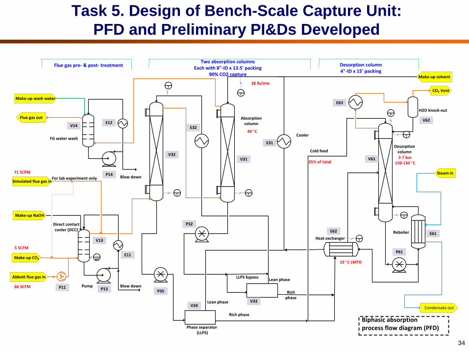
Task 5. Design of Bench-Scale Capture Unit:
PFD and Preliminary PI&Ds Developed
34
TT
Make-up wash water
Flue gas out
Steam in
Condensate out
Make-up solvent
Biphasic absorption process flow diagram (PFD)
Abbott flue gas in
T
T
Simulated flue gas in
Make-up CO2
Make-up NaOH
pH
T
T
T
CO2 Vent
P
Lean phase
LLPS bypass
Phase separator (LLPS)
Absorption column
Desorption column
Direct contact cooler (DCC)
FG water wash
Reboiler
Pump
Heat exchanger
Cold feed
H2O knock-out
Blow down66 SCFM
35% of total
10 C LMTD
2-7 bar120-150 C
40 C
Flue gas pre- & post- treatmentTwo absorption columns
Each with 8"-ID x 13.5' packing90% CO2 capture
Desorption column4"-ID x 15' packing
Lean phase
Rich phase
Rich phase
Cooler
For lab experiment only Blow down
71 SCFM
5 SCFM
28 lb/min
P32
E11
P14
P35P13P11
V33V34
P61
E63
V32V31 V61
V14V62
E31
V13
E12
E62E61
E32

Contn’d
35
Gas vent to stack
Direct contact
cooler/SO2
polisher
NaOH solution makeup
Flue gas
Stripper with a cold and a heated solvent feed
High-pressure stripper
Water knockout
Cooler
CoolerCooler
LP steam
Condensate
CO2 bottle gas (if needed)
2 stages of absorption & phase separation
Flue gas cooling and polishing treatment
Absorber
Phase separator
Water wash
Reboiler
Blowdown
Solvent makeup
Cold feed
Heated feed
Heat exchanger

Equipment List and Preliminary Specifications Developed
Preliminary specs prepared
for major equipment items:
Gas blower (1)
Pumps (7)
Heat exchangers (7)
DCC/SO2 polisher (1)
Absorber (1)
Stripper (1)
Tanks & phase
separators (5)
36
PIxx
TIxx
LIxx
Back pressure valve
Steam trap
Ball valve
Needle valve
Strainer
Three-way ball valve
Ball valve
Needle valve
Safety valve
Control valve
Vessel (pre- and post- treatment)
Vessel (Absorption, desorption)
Vessel (storage)
Heat exchange (type 1)
Heat exchange (type 2)
Gas blower
Pump (low pressure)
Pump (high pressure)
Vxx, Exx, Pxx
Item #
Check valve
Static mixer
1x, 2xPre- & Post- FG treatment section
3x, 4x, 5x Absorption section
Coupon
6x, 7x Desorption section
8x, 9x Steam & Cooling water section
xTxx
Measurement w transmitter
Flow meter (high pressure)
Flow meter
Pressure meter
Temperature meter
Liquid level meter
VW
View window
Static mixer
Liquid process pipe line (amines, NaOH, H2O)
Gas process pipe line (Flue gas, CO2)
Cooling water pipe line
Steam/condensate pipe line
Instrument signal pipe line
LPxxxLiquid process pipe line (amine, NaOH, H2O)
GPxxxGas process pipe line (Flue gas, CO2)
WP9xxCooling water pipe line
SP8xxSteam/condensate pipe line
LVxxxLiquid process line valve (amine, NaOH, H2O)
GVxxxGas process line valve (Flue gas, CO2)
WV9xx Cooling water line valve
SV8xxSteam/condensate line valve
S51
Yxx Sampling port
XICxxAuto control loop w meter and control valve
Yxx Pipe line strainer

Site Data Prepared for Bench-Scale Skid Design
Site data collected for Abbott power plant and lab (or outdoor lab):
Location data (e.g., elevation and seismic zone);
Climate data;
Electrical classification;
Utilities requirements (e.g., sources, specs, connection);
Process operation, control and monitoring requirements;
Construction design basis (e.g., site layout, footprint, allowable structural
load, heat tracing requirements);
Process design data (e.g., flue gas specs, discharge specs, materials
compatibility, CO2 removal %, test matrix)
37

Contn’d
Expected location of bench scale test skid at Abbott power plant
(continuous testing for 2 weeks)
38
ESP
STACK
BENCHCARBON CAPTURE
ABBOTT POWER PLANT
JBR FGD BUILDING

Contn’d
Component Unit Design
*CO2 vol% 5.7
O2 vol% 10.3
N2 + Ar vol% 69.6
H2O vol% 14.4
SO2 ppmv 68
SO3 ppmv 15
NOx ppmv 211
HCl ppmv 0.73
PM grains/dscf 0.00223
T °F 200
P psig Minimal to negative
Flow rate scfm 71 scfm
39
* CO2 concentration in Abbott flue gas will be increased to ~13 vol% by
adding CO2 bottle gas
(CO2 addition will slightly dilute flue gas (by ~8%); So levels of other flue gas
components will only slightly change and still remain representative)
Flue gas entering the bench-scale skid at Abbott power plant:

Preliminary HAZOP What-If Analysis Conducted
Preliminary HAZOP What-If analysis conducted for absorption/phase
separation and desorption systems based on preliminary P&IDs
developed
Answers to What-If questions provided, and recommendations made
for future consideration
A report of findings prepared by Trimeric
Final HAZOP analysis will be conducted in BP2; UIUC Facilities &
Services and Abbott power plant personnel will be engaged
40

Summary of BP1 Work Activities
Task 2: Developing and Implementing a TMP
Performance attributes to be tested and performance requirements defined
Task 3: Studies of Solvent Volatility and Losses
Total volatilities of two biphasic solvents were ~2-4 times > 30 wt% MEA due to their
lean water content (≤30 wt% water)
Water wash experimental setups validated
BiCAP-1 vapor emissions after water wash MEA (40-70% removal by water wash)
15-25% aerosol removal by water wash (3’ structured packing in current setup)
Task 4: Modeling and Optimization of Biphasic CO2 Absorption Process
Cold-Bypass BiCAP configuration identified to be most energy efficient
Optimal 40 kWe bench-scale unit design with a reboiler heat duty of 2,210 kJ/kg
CO2 at 6.0 bar stripping pressure identified (based on BiCAP-1 solvent)
Task 5: Design of Bench-Scale Capture Unit
PFD, preliminary P&IDs, equipment list & preliminary specs developed
Most site info collected
A preliminary HAZOP what-if analysis conducted41

Fulfillment of BP1 Success Criteria
42
Basis for Decision/Success Criteria Status
(1) Successful completion of all work
proposed in BP1
All work projected to complete by end of BP1
(2) Development and submission of a
Technology Maturation Plan
Completed as scheduled
(3) Completion of solvent volatility
measurements and a preliminary
assessment of water wash options and
performance to provide inputs for
equipment design
Completed as scheduled
(4) Host site agreement finalized Completed as scheduled (Agreement Letter for
testing at Abbott power plant submitted)
(5) Completion of the 40 kWe bench-scale
capture equipment design based on the
optimal process identified, with design
calculations showing that the unit can
meet the performance targets (e.g., heat
duty ≤2,100 kJ/kg of CO2 and stripping
pressure 4 bar)
Most work completed; Review/revision to
complete by end of BP1:
Optimal process for bench-scale unit for
BiCAP-1 solvent was identified;
Design calculations showed potential to reach
performance targets (2,210 kJ/kg of CO2 at 6
bar for BiCAP-1; expected close to 2,100
kJ/kg of CO2 for BiCAP-2)

Project Overview
Technical Background
BP1 Work and Budget Status
BP1 Technical Activities and Major Findings
BP2 & BP3 Work Plan, Budget Plan and Milestones
43
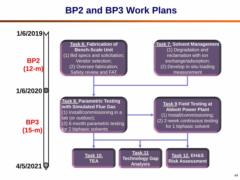
BP2 and BP3 Work Plans
44
4/5/2021
BP2
(12-m)
BP3
(15-m)
1/6/2019
1/6/2020
Task 6. Fabrication of
Bench-Scale Unit
(1) Bid specs and solicitation;
Vendor selection;
(2) Oversee fabrication;
Safety review and FAT
Task 7. Solvent Management
(1) Degradation and
reclamation with ion
exchange/adsorption;
(2) Develop in-situ loading
measurement
Task 8. Parametric Testing
with Simulated Flue Gas
(1) Install/commissioning in a
lab (or outdoor);
(2) 6-month parametric testing
for 2 biphasic solvents
Task 9 Field Testing at
Abbott Power Plant
(1) Install/commissioning;
(2) 2-week continuous testing
for 1 biphasic solvent
Task 10.
TEA
Task.11
Technology Gap
Analysis
Task 12. EH&S
Risk Assessment

BP2 and BP3 Budget Plans
No change requested for BP2 budget plan
Equipment cost of $675,000 budgeted in BP2 to build a 40 kWe unit and
accessories; Cost to be monitored and communicated when detailed bid
specs developed for solicitation
45
BP2 Budget Plan
(US$)
BP3 Budget Plan
(US$)
DOE share 1,472,493 $1,047,349
Recipient cost share $368,328 $264,990
Total $1,840,821 $1,312,339

BP2 and BP3 Milestones
46
BPTask
No.Milestone description
Planned
completionVerification method
2 6h. Bench-scale unit fabricated and
factory-acceptable test completed12/31/19
Description and photographs
provided in QR report
2 7i. Solvent reclamation options
identified9/30/19 Results reported in QR report
3 8.1j. Bench-scale unit installed on the
skid3/31/20
Description and photographs
provided in QR report
3 8.2k. Parametric testing of the bench-
scale unit completed9/30/20 Results reported in QR report
3 9 l. Field test plan prepared 11/30/20Field test plan reported in QR
report
3 9
m. Field testing with a slipstream of
coal- combustion flue gas
completed
12/31/20 Results reported in QR report
3 10 n. TEA topical report completed 3/31/21Results reported in QR report and
a topical report
3 10 o. State-Point Data Table updated 3/31/21Updated State-Point Data Table
reported in QR report
3 11p. Technology Gap Analysis topical
report completed3/31/21
Results reported in QR report and
a topical report
3 12q. EH&S Risk Assessment topical
report completed3/31/21
Results reported in QR report and
a topical report

Acknowledgements
47
Funding Support by USDOE/NETL through Cooperative
Agreement No. DE-FE0026434
DOE/NETL Project Manager: Andrew Jones
Aspen Technology for providing free license of aspenONE
software