Embed Size (px)
Citation preview

고급소프트웨어공학
#2 Attribute Driven Design (ADD)- 고급소프트웨어공학 Team 4 -
31th May 2021
김상권, 이태영, 배재욱

고급소프트웨어공학
2
Contents
■ Attribute Driven Design (ADD)
ADD introduction
Design process
– Iteration 1: Establishing an initial overall system structure
– Iteration 2: Identifying structure to support primary functionality
– Iteration 3: Refining previously created structures to fully address the remaining drivers

고급소프트웨어공학
ADD introduction

고급소프트웨어공학
4
ADD design process
■ 5가지요소로구성된 Architectural Driver 를기반으로 requirements 를 architecture structure 로translate 하는과정
Architectural Driver 는 input 으로 사용
– Stakeholders 를 소집하여 Quality Attribute Workshop
(QAW) 를 통해 찾음
3 회 정도 iteration 진행
ADD 최종 산출물: Software Architecture Design
고급소프트웨어공학
5
ADD design process
■ 각 Iteration 별 Goal 및 Design concepts 결정
Iteration 1
– Goal: 초기 전반적인시스템구조 결정
– 관련 Design concepts: Ref. architectures, deployment
patterns, externally developed components
Iteration 2
– Goal: Primary functionality 를 만족하기위한구조 선정
– 관련 Design concepts: Architectural patterns,
externally developed components
Iteration 3
– Goal: 남은 drivers 요소를 고려하도록기존 구조정제
– 관련 Design concepts: Tactics, architectural patterns,
deployment patterns, externally developed
components

고급소프트웨어공학
6
ADD design process
■ Iteration 마다해야할단계별프로세스
(Step 1: Review inputs) ➔ not iteration
Step 2: Establish iteration goal by selecting drivers
Step 3: Choose one or more elements of the system to refine
Step 4: Choose one or more design concepts that satisfy the selected drivers
Step 5: Instantiate architectural elements, allocate responsibilities and define interfaces
Step 6: Sketch views and record design decisions
Step 7: Perform analysis of current design and review iteration goal and achievement of design purpose

고급소프트웨어공학
ADD Design process: iteration 1

고급소프트웨어공학
8
Step 1: Review inputs
■ Selected Architectural Drivers
ID Concern
CRN-1 처음에 전반적인 system architecture 부터설계한다.
CRN-2 개발 환경은 프로그램개발자와 네트워크 개발자가 익숙한 것을 선택한다.
CRN-3 모든 Architectural Driver를 만족하는 Software Architecture 를세운다.
CRN-4 사용자에게 적합한 UI/UX design 개발
CRN-5 사용자의 요구를 분석하여그것들을 컴퓨터에 저장할 수 있는 데이터베이스의구조에 맞게 변형한후 특정 DBMS로 데이터베이스를 구현
CRN-6 웹 방화벽 구축, 침입탐지시스템 등 정보보호를 위한 관리적 기술적물리적인시스템 구축
ID Constraints
CON-1 각 자판기는 모두네트워크에 연결되어 있고 네트워크 연결 정보는 미리알고 있다(최대 10대).
CON-2 자판기의 판매 음료종류는 사전에 결정된다.
CON-3 자판기 사이의 msg protocol은사전에 결정된다.
Design Decisions and
Location
Rationale
UC-1: Manage database 총 음료의 개수는 20 종류이다.
UC-2: Display information 한 자판기는 7 종류의 음료를 판매하며, 판매하지않는 음료도 메뉴는 제공한다.
UC-3: Process tasks 사용자가 음료를 선택후 결제하면 음료가 제공된다.
결제는 카드로 하고, 잔액이 부족한 경우 결제되지 않는다.
UC-4: Manage network 음료 재고가 부족하거나자판기에서 판매하지 않는 음료를 구매하려는 경우 다른자판기 재교 확인 후 위치를안내한다. 이 때, 네트워크 상의자판기에 broadcast msg를통해 재고확인을 요청하여 확인하고, 네트워크 msg를통해 대상 자판기의위치를 확인하여 안내한다.
UC-5: Identification 다른 자판기의 음료구매에 대해 선결제를 할 수 있다. 이 때, 현재 자판기에서 결제후 인증 코드를 발급하며 다른자판기로 가서 인증코드를 입력하면 음료가 나온다.
Quality Attribute Scenario Associated
Use Case
QA-1: Marketability 기존 코드 중재활용 가능한 부분의 활용을 통헤 낮은 개발비용/ 빠른개발속도를 달성해야 한다.
ALL
QA-2: Usability SW의기능이분명하고 간결하며 사용이 편리해야 한다. UC-3, 4, 5
QA-3: Usability 모든 구매한 물품과비용이 한 눈에 보일 수 있게 해야한다.
UC-1, 2
QA-4: Performance 화면 사이의 연결이나연동이 사용자로 하여금 불편함을느끼지 않도록 0.5초이내로제한한다.
UC-3, 4, 5
QA-5: Availability 자판기 작동 시일주일 정도는 이상 없이 동작해야 한다. ALL
QA-6: Modifiability 음료 메뉴 추가나삭제가 용이했으면 좋겠다. UC-1

고급소프트웨어공학
9
Step 2: Establish iteration goal by selecting drivers
■ Iteration goal 선택
전체 Architectural Drivers 를 만족할 수 있는 초기 전반적인 시스템 구조 결정

고급소프트웨어공학
10
Step 3: Choose one or more elements of the system to refine
■ Iteration goal 인초기전반적인시스템구조결정을위해 DVM 시스템을 elements로선택
카드 결제 단말기시스템
DVM systemOther DVMsOther DVMs
Other DVMsOther DVMs
Database server
System under development
External system
Data flow

고급소프트웨어공학
11
Step 4: Choose One or More Design Concepts that Satisfy the Selected Derivers
■ Choosing design concepts
ID Constraints
CON-1 각 자판기는 모두네트워크에 연결되어 있고 네트워크 연결정보는 미리 알고있다(최대 10대).
CON-2 자판기의 판매 음료종류는 사전에 결정된다.
CON-3 자판기 사이의 msg protocol은사전에 결정된다.
Design Decisions and
Location
Rationale
Logically structure the
client part using the Rich
Client Application
reference architecture
DVM system 은 client part 역할이며, UC-2, UC-3, UC-4, UC-5 처럼 대부분 기능 요구사항을해결할 수 있는 능력이 필요함. 따라서 수행 capability 가 큰 rich client application 을 선택
Discarded
alternatives
web application, rich internet application을 고려하였으나, DVM 요구사항에는 인터넷이 필요하지 않기 때문에 선정하지 않음
Logically structure the
server part of the system
using the Service
Application reference
architecture
UI 제공이 필요하지 않고, UC-1, QA-6를 만족시키기 위해 데이터베이스 관리를 할 수 있는application 필요
Discarded
alternatives
No discarded alternatives
Design
Decisions and
Location
Rationale
UC-1: Manage
database
총 음료의 개수는 20 종류이다.
UC-2: Display
information
한 자판기는 7 종류의 음료를 판매하며, 판매하지않는 음료도 메뉴는 제공한다.
UC-3: Process
tasks
사용자가 음료를 선택후 결제하면 음료가 제공된다.
결제는 카드로 하고, 잔액이 부족한 경우 결제되지 않는다.
UC-4: Manage
network
음료 재고가 부족하거나자판기에서 판매하지 않는 음료를구매하려는 경우 다른자판기 재교 확인 후 위치를 안내한다. 이때, 네트워크 상의 자판기에 broadcast msg를통해재고 확인을 요청하여확인하고, 네트워크 msg를통해대상 자판기의 위치를확인하여 안내한다.
UC-5:
Identification
다른 자판기의 음료구매에 대해 선결제를 할 수 있다. 이때, 현재자판기에서 결제 후 인증 코드를 발급하며 다른자판기로 가서 인증코드를입력하면 음료가 나온다.

고급소프트웨어공학
12
Step 4: Choose One or More Design Concepts that Satisfy the Selected Derivers
■ Rich client application reference architecture ■ Service client application reference architecture
Client
User interface
UI Process Logic
Application Facade
Business
Workflow
Business
Logic
Business
Entities
Data
AccessHelpers and
Utilities
Service
AgentsS
ecurity
Opera
tio
nal M
anagem
ent
Com
munic
atio
n
(from presentation layer)
(from business layer)
(from data layer)
Cross-cutting
Server
Services Interfaces
Message Types
Application Facade
Business
Workflow
Business
Logic
Business
Entities
Data
AccessHelpers and
Utilities
Service
Agents
Security
Opera
tio
nal M
anagem
ent
Com
munic
atio
n
(from services layer)
(from business layer)
(from data layer)
Cross-cutting
Other systems Other systems
Local data sources
Data sources Data sources

고급소프트웨어공학
13
Step 4: Choose One or More Design Concepts that Satisfy the Selected Derivers
■ Choosing design concepts
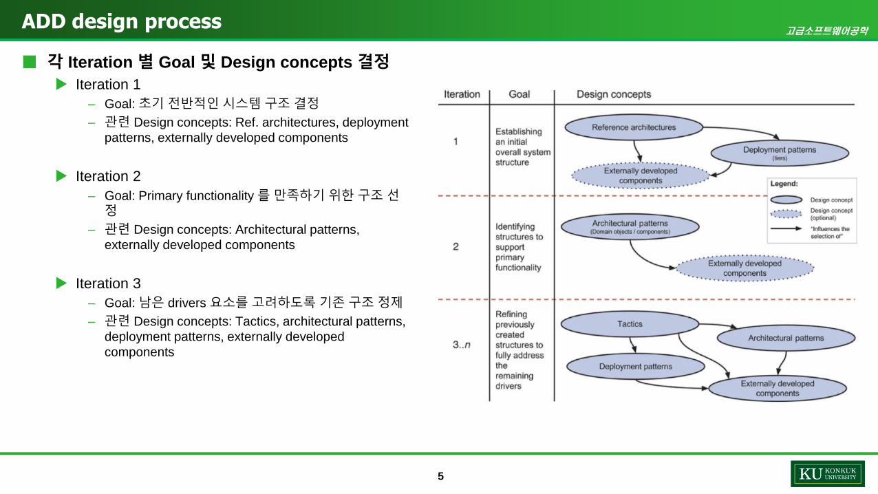
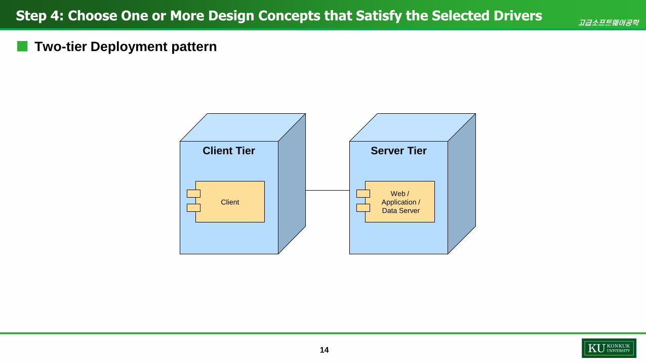
Physically structure the application using the Two-tier Deployment pattern
Design Decisions and
Location
Rationale
Physically structure the
application using the
Two-tier Deployment
pattern
QA-1, 2을 고려하여 배포할 시스템의 아키텍쳐는 간단할 수록 좋고, 각각의 DVM은 Web
application을 거치지 않고 직접 database server에 접근하므로 two-tier deployment pattern
이 적절하다고 판단
Discarded
alternatives
No discarded alternatives
ID Concern
CRN-1 처음에 전반적인 system architecture 부터설계한다.
CRN-2 개발 환경은 프로그램개발자와 네트워크 개발자가 익숙한것을 선택한다.
CRN-3 모든 Architectural Driver를 만족하는 Software Architecture
를 세운다.
CRN-4 사용자에게 적합한 UI/UX design 개발
CRN-5 사용자의 요구를 분석하여그것들을 컴퓨터에 저장할 수 있는 데이터베이스의 구조에맞게 변형한 후 특정 DBMS로 데이터베이스를 구현
CRN-6 웹 방화벽 구축, 침입탐지시스템 등 정보보호를 위한 관리적기술적 물리적인 시스템구축
고급소프트웨어공학
14
Step 4: Choose One or More Design Concepts that Satisfy the Selected Drivers
■ Two-tier Deployment pattern
Client Tier
Client
Server Tier
Web /
Application /
Data Server

고급소프트웨어공학
15
Step 5: Instantiate Architectural Elements, Allocate Responsibilities, and Define Interfaces
Design Decision and Location Rationale
Remove local data sources in the
rich client application
It is believed that there is no need to store data locally, as the
network connection is generally reliable. also, communication with
the server is handled in the data layer. internal communication
between components in the client is managed through local
method calls and does not need particular support
Create a module dedicated to
accessing the database servers
of DVM stock in the data layer of
the Service Application reference
architecture.
The service agents component from the reference architecture is
adapted to abstract the access to the database servers of DVM
stock. this will play a critical role in the achievement of UC-4 and
UC-5. as shown in CON-1, all vending machines are connected to
the network, and you need to know the network connection
information.

고급소프트웨어공학
16
Client
Step 6: Sketch views and record design decisions
■ Reference Architecture Selection
User interface
UI Process Logic
Application Facade
Business
Workflow
Business
Logic
Business
Entities
Data
AccessHelpers and
Utilities
Service
Agents
Security
Opera
tio
nal M
anagem
ent
Com
munic
atio
n
(from presentation layer)
(from business layer)
(from data layer)
Cross-cutting
Other systemsData sources
Server
Services Interfaces
Message Types
Application Facade
Business
Workflow
Business
Logic
Business
Entities
Data
AccessHelpers and
Utilities
Service
Agents
Security
Opera
tio
nal M
anagem
ent
Com
munic
atio
n
(from services layer)
(from business layer)
(from data layer)
Cross-cutting

고급소프트웨어공학
17
Step 6: Sketch views and record design decisions
■ Module View
<Layer>
Presentation CS
UI Modules UI Process Modules
<Layer>
Business logic CS
Business Modules CS Business Entities CS
<Layer>
Data CS
Communication Modules
<Layer>
Cross-cuting CS
Security Module CS
Op. Mgnt Modules CS
Client Side
<Layer>
Services SS
Service Interfaces
<Layer>
Business logic SS
Business Modules CS Business Entities CS
<Layer>
Data SS
DB Access Module
<Layer>
Cross-cuting CS
Security Module CS
Op. Mgnt Modules CS
Server Side
Communication Module CS

고급소프트웨어공학
18
■ Element Descriptions
Responsibility
Step 6: Sketch views and record design decisions
Element Responsibility
Presentation Client
side(CS)
이 계층에는 사용자 상호 작용 및 사용 사례 제어 흐름을 제어하는모듈이 포함됩니다.
Business logic CS 이 계층에는 Client 측에서 내부적으로 실행할 수 있는 business
logic operations을수행하는 모듈이 포함되어 있습니다.
Data CS 이 계층에는 서버와의 통신을 담당하는 모듈이 포함되어 있습니다.
Cross-cutting CS 이 계층에는 보안, 로깅 및 I / O와같은 여러 계층을 가로 지르는 기능이 있는 모듈이 포함됩니다.
이것은 드라이버 중 하나라도 CRN-6을 달성하는데 도움이됩니다.
UI modules 이 모듈은 사용자 인터페이스를 렌더링하고 사용자 입력을 받습니다.
UI process modules 이 모듈은 모든 시스템 사용 사례 (화면 간 탐색 포함)의 제어 흐름을 담당합니다.
Business modules CS 이 모듈은 로컬에서 수행 할 수 있는 비즈니스 운영을 구현하거나서버 측에서 비즈니스 기능을 노출합니다.
Business entities CS 이 엔티티는 도메인 모델을 구성합니다. 그들은 서버 측보다 덜 상세 할 수 있습니다.
Communication
modules CS
이 모듈은 서버 측에서 실행되는 애플리케이션에서 제공하는 서비스를 사용합니다.
Element Responsibility
Services server side
(SS)
이 계층에는 클라이언트가 사용하는 서비스를 노출하는 모듈이 포함되어 있습니다.
Business logic SS 이 계층에는 서버 측에서 처리해야하는 비즈니스 논리 작업을 수행하는 모듈이 포함되어 있습니다.
Data SS 이 계층에는 데이터 지속성 및 시간 서버와의 통신을 담당하는 모듈이 포함되어 있습니다.
이것은 QA-5을 달성하는 데 도움이 됩니다.
Cross-cutting SS 이러한 모듈에는 보안, 로깅 및 I / O와 같은 여러 계층에 걸친 기능이 있습니다.
Service Interfaces SS 이 모듈은 클라이언트가 사용하는 서비스를 노출합니다.
Business modules CS 이 모듈은 비즈니스 운영을 구현합니다.
Business entities CS 이 엔티티는 도메인 모델을 구성합니다.
DB access module 이 모듈은 관계형 데이터베이스에 대한 비즈니스 항목 (객체)의 지속성을 담당합니다. 그것은 객체 지향 관계형 매핑을 수행하고 지속성 세부 사항에서 응용 프로그램의 나머지 부분을 보호한다.
Time Server access
module
이 모듈은 시간 서버와의 통신을 담당합니다. 다양한 유형의 시간서버와의 통신을 지원하기 위해 시간 서버와의 작업을 격리하고 추상화합니다. (UC-4 참조).

고급소프트웨어공학
19
Step 7: Perform analysis of current design and review iteration goal and achievement of design purpose
Not Addressed Partially Addressed Completely Addressed Design Decisions Made During the Iteration
UC-1 Server의 Reference architecture를선정함에 있어 부분적으로고려됨
UC-2 Reference architecture를 rich client application으로선정함에 있어 부분적으로고려되었음
UC-3 Reference architecture를 rich client application으로선정함에 있어 부분적으로고려되었음
UC-4 Reference architecture를 rich client application으로선정함에 있어 부분적으로고려되었음
UC-5 Reference architecture를 rich client application으로선정함에 있어 부분적으로고려되었음
QA-1 Reference architecture와 Deploy pattern을선정함에있어 부분적으로 고려되었음
QA-2 Reference architecture와 Deploy pattern을선정함에있어 부분적으로 고려되었음
QA-3
QA-4
QA-5
QA-6 Server의 Reference architecture를선정함에 있어 부분적으로고려됨
CRN-1 해당 Concern을고려하여 System의 architecture는 Green field에서설계되었음.
CRN-2
CRN-3 해당 Concern을고려하여 architecture 설계 과정에서 모든 Architectural Driver를 고려함
CRN-4 해당 Concern을고려하여 Client architecture 선정
CRN-5 Server architecture에해당 Concern 부분 반영
CRN-6 해당 Concern을반영하여 Server architecture 선정
CON-1 부분 반영
CON-2
CON-3
고급소프트웨어공학
ADD Design process: iteration 2

고급소프트웨어공학
21
Step 1: Review inputs
■ Selected Architectural Drivers
ID Concern
CRN-1 처음에 전반적인 system architecture 부터설계한다.
CRN-2 개발 환경은 프로그램개발자와 네트워크 개발자가 익숙한 것을 선택한다.
CRN-3 모든 Architectural Driver를 만족하는 Software Architecture 를세운다.
CRN-4 사용자에게 적합한 UI/UX design 개발
CRN-5 사용자의 요구를 분석하여그것들을 컴퓨터에 저장할 수 있는 데이터베이스의구조에 맞게 변형한후 특정 DBMS로 데이터베이스를 구현
CRN-6 웹 방화벽 구축, 침입탐지시스템 등 정보보호를 위한 관리적 기술적물리적인시스템 구축
ID Constraints
CON-1 각 자판기는 모두네트워크에 연결되어 있고 네트워크 연결 정보는 미리알고 있다(최대 10대).
CON-2 자판기의 판매 음료종류는 사전에 결정된다.
CON-3 자판기 사이의 msg protocol은사전에 결정된다.
Design Decisions and
Location
Rationale
UC-1: Manage database 총 음료의 개수는 20 종류이다.
UC-2: Display information 한 자판기는 7 종류의 음료를 판매하며, 판매하지않는 음료도 메뉴는 제공한다.
UC-3: Process tasks 사용자가 음료를 선택후 결제하면 음료가 제공된다.
결제는 카드로 하고, 잔액이 부족한 경우 결제되지 않는다.
UC-4: Manage network 음료 재고가 부족하거나자판기에서 판매하지 않는 음료를 구매하려는 경우 다른자판기 재교 확인 후 위치를안내한다. 이 때, 네트워크 상의자판기에 broadcast msg를통해 재고확인을 요청하여 확인하고, 네트워크 msg를통해 대상 자판기의위치를 확인하여 안내한다.
UC-5: Identification 다른 자판기의 음료구매에 대해 선결제를 할 수 있다. 이 때, 현재 자판기에서 결제후 인증 코드를 발급하며 다른자판기로 가서 인증코드를 입력하면 음료가 나온다.
Quality Attribute Scenario Associated
Use Case
QA-1: Marketability 기존 코드 중재활용 가능한 부분의 활용을 통헤 낮은 개발비용/ 빠른개발속도를 달성해야 한다.
ALL
QA-2: Usability SW의기능이분명하고 간결하며 사용이 편리해야 한다. UC-3, 4, 5
QA-3: Usability 모든 구매한 물품과비용이 한 눈에 보일 수 있게 해야한다.
UC-1, 2
QA-4: Performance 화면 사이의 연결이나연동이 사용자로 하여금 불편함을느끼지 않도록 0.5초이내로제한한다.
UC-3, 4, 5
QA-5: Availability 자판기 작동 시일주일 정도는 이상 없이 동작해야 한다. ALL
QA-6: Modifiability 음료 메뉴 추가나삭제가 용이했으면 좋겠다. UC-1

고급소프트웨어공학
22
Step 2: Establish iteration goal by selecting drivers
■ Iteration goal
Identifying structures to support primary functionality
– Use case 모두 completely addressed 되도록 하는 것을 목표!

고급소프트웨어공학
23
Step 3: Choose one or more elements of the system to refine
■ 세부구조를 Use case 고려하기위해각 layers 및 modules를 element로선택
<Layer>
Presentation CS
UI Modules UI Process Modules
<Layer>
Business logic CS
Business Modules CS Business Entities CS
<Layer>
Data CS
Communication Modules
<Layer>
Cross-cuting CS
Security Module CS
Op. Mgnt Modules CS
Client Side
<Layer>
Services SS
Service Interfaces
<Layer>
Business logic SS
Business Modules CS Business Entities CS
<Layer>
Data SS
DB Access Module
<Layer>
Cross-cuting CS
Security Module CS
Op. Mgnt Modules CS
Server Side
Communication Module CS

고급소프트웨어공학
24
Step 4: Choose One or More Design Concepts that Satisfy the Selected Drivers
■ Design concept: architectural design patterns
■ Selection of design concepts
Domain Model
Domain Objects
Decompose Domain Objects into general and specialized Components
Design Decision and Location Rationale
Create a Domain model 기능세분화전에시스템에대한초기 domain model 을생성하여도메인의주요 elements 를식별해야한다.
Identify Domain Objects that map
to functional requirements
Use cases 를빌딩블록하나에캡슐화하기위해 domain objects
를결정
Decompose Domain Objects into
general and specialized
Components
생성한 Domain objects를각각계층내에있는세분화된 elements
로분해가필요하다.

고급소프트웨어공학
25
Step 5: Instantiate Architectural Elements, Allocate Responsibilities, and Define Interfaces
Design Decision and Location Rationale
Create a Domain model Primary use cases와관련된초기 domain model 을생성하여디자인단계를가속화한다.
Identify Domain Objects that map
to functional requirements
도메인개체의초기식별은시스템의 use cases 를분석하여만들수있습니다.
Decompose Domain Objects into
general and specialized
Components by layer-specific
modules with an explicit interface
모든 Primary use cases에대해앞서식별해둔 domain objects 를세분화하고연결하기위해 layer-specific modules 을식별한다.

고급소프트웨어공학
26
Step 6: Sketch views and record design decisions
■ Initial domain model
Data database
- MenuData
Server
- ReliatedClientName
- Address
- MenuData
Client
- ClientName
- IDs
- Requests
Event
- Type
- Date
Configuration
- ConfigurationParameters

고급소프트웨어공학
27
Step 6: Sketch views and record design decisions
■ Domain Objects Associated with Use Cases
<domain object>
Manage database
Responsibilities
UC-1
<domain object>
Display information
Responsibilities
UC-2
<domain object>
Process tasks
Responsibilities
UC-3
<domain object>
Manage network
Responsibilities
UC-4
<domain object>
Identification
Responsibilities
UC-5

고급소프트웨어공학
28
Step 6: Sketch views and record design decisions
■ Module view
<Layer>
Presentation CS
<Layer>
Business logic CS
<Layer>
Data CS
NetworkManager
Client Side
<Layer>
Services SS
RequestService
<Layer>
Business logic SS
<Layer>
Data SS
DataManager
Server Side
MenuDisplay
Viewer
MenuDisplay
Controller
MenuDisplay
Status
NetworkManager
고급소프트웨어공학
29
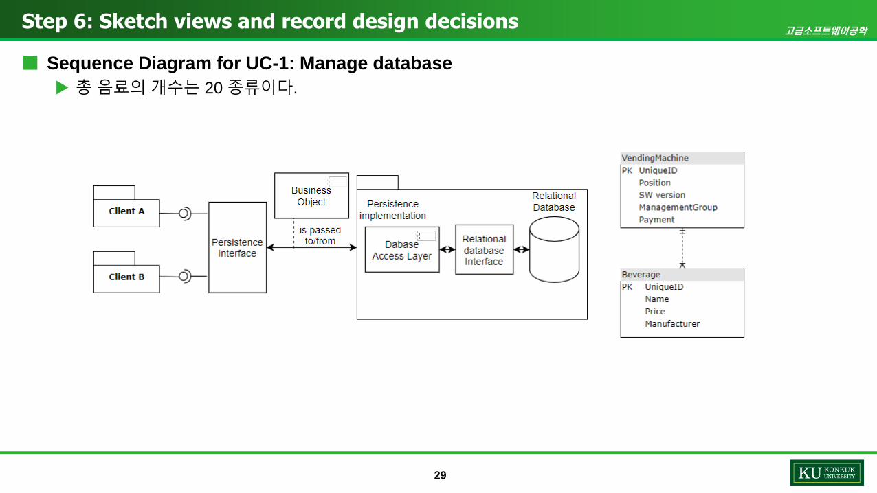
Step 6: Sketch views and record design decisions
■ Sequence Diagram for UC-1: Manage database
총 음료의 개수는 20 종류이다.

고급소프트웨어공학
30
Step 6: Sketch views and record design decisions
■ Sequence Diagram for UC-1: Manage database
총 음료의 개수는 20 종류이다.
<domain object>
Manage database
Responsibilities
UC-1
:MenuDisplayViewer :MenuDisplayController :MenuDisplayStatus
Client
EventWaitHandler
ShowPurchase
DrinkListEventChangeMenuDispla
yStatus
RespondMenuDispl
ayStatus
RespondResult
ChangeMenuDispla
yStatus
RespondMenuDispl
ayStatus
RespondResult
ShowSpecific
DrinkInfoEvent

고급소프트웨어공학
31
Step 6: Sketch views and record design decisions
■ Interfaces from UC-1 Sequence Diagram
Method Name Description
Element: MenuDisplayViewer
EventWaitHandler 사용자가이벤트를발생시키는것을기다림
ShowPurchaseDrinkListEvent 구매할수있는모든음료리스트보기이벤트발생
ShowSpecificDrinkInfoEvent 판매음료중세부정보보기
Element: MenuDisplayController
ChangeMenuDisplayStatus 내부 State machine 상태를모든음료리스트보기로변경
RespondResult 사용자에게모든음료리스트보기
Element: MenuDisplayStatus
RespondMenuDisplayStatus 내부 State machine 상태응답

고급소프트웨어공학
32
Step 6: Sketch views and record design decisions
■ Sequence Diagram for UC-2: Display information
한 자판기는 7종류의 음료 판매
판매하지 않는 음료도 메뉴는 제공
<domain object>
Display information
Responsibilities
UC-2
:MenuDisplayViewer :MenuDisplayController :MenuDisplayStatus
Client
EventWaitHandler
ChangeDrink
CategoryEvent
ChangeMenu
DisplayStatus
RespondMenu
DisplayStatus
RespondResult

고급소프트웨어공학
33
Step 6: Sketch views and record design decisions
■ Interfaces from UC-2 Sequence Diagram
Method Name Description
Element: MenuDisplayViewer
EventWaitHandler 사용자가이벤트를발생시키는것을기다림
ChangeDrinkCategoryEvent 현재자판기판매하는(7 종류)/ 판매하지않는, 이온/탄산등 category 분류이벤트발생
Element: MenuDisplayController
ChangeMenuDisplayStatus Category 분류에따른내부 State machine 상태변경
RespondResult 사용자에게 Category에따른음료리스트보기
Element: MenuDisplayStatus
RespondMenuDisplayStatus 내부 State machine 상태응답

고급소프트웨어공학
34
Step 6: Sketch views and record design decisions
■ Sequence Diagram for UC-3: Process tasks 사용자가음료를선택 후 결제하면음료가제공된다.
결제는카드로 하고, 잔액이부족한경우 결제되지않는다.
:MenuDisplayViewer :MenuDisplayController :NetworkManager
Client
SendPurchaseEvent
음료선택
RequsetChangeSrock
ResponseStockData음료재고표시
InvokePurchaseEvent
ResponseResultResponseResult/결과표시
:RequestService :DataManager :NetworkManager
Server
RequestStockMsg
ResponseStockData
RequestStockData
RequestStockData
ResponseStockMsgResponseStockData
ResponseStockData
RequsetChangeSrock
RequsetChangeSrock

고급소프트웨어공학
35
Step 6: Sketch views and record design decisions
■ Interfaces from UC-3 Sequence Diagram
Method Name Description
Element: MenuDisplayViewer
SendPurchaseEvent 사용자 구매 요청 이벤트 발생
음료 재고 표시 음료 재고 표시
결과 표시 음료 구매에 대한 처리 결과 응답
Element: MenuDisplayController
InvokePurchaseEvent 구매 요청 이벤트 호출
ResponseStockData 음료 재고에 대한 처리 결과 응답
ResponseResult 음료 구매에 대한 처리 결과 응답
Element: NetworkManager
RequestStockData 서버에 음료 재고 정보 요청
ResponseStockData 서버에서 음료 재고 정보를 받아 응답
ResponseResult 음료 구매에 대한 처리 결과를 응답
RequsetChangeSrock 구매로 인한 재고 변동사항애 대한 DB 수정 요청
Element: RequestService
RequestStockData 음료 재고 정보 요청
ResponseStockData 음료 재고 정보를 자판기에 응답
RequsetChangeSrock 구매로 인한 재고 변동사항을 DB로 전달
Element: DataManager
RequestStockMsg DB에 음료 재고 정보 요청
ResponseStockData 음료 재고 정보를 받아 응답
RequsetChangeSrock 구매로 인한 재고 변동사항애 대한 DB 수정 요청
Element: NetworkManager
ResponseStockMsg DB에서 음료 재고 정보를 받아 응답
고급소프트웨어공학
36
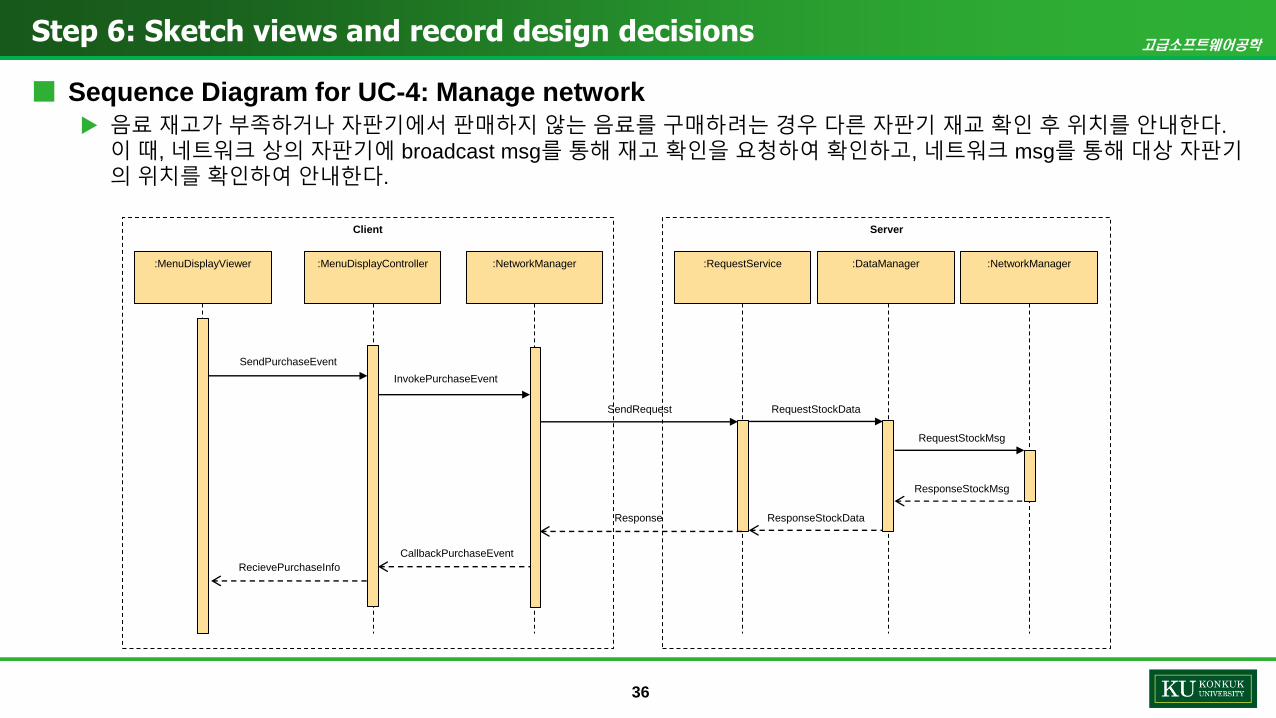
Step 6: Sketch views and record design decisions
■ Sequence Diagram for UC-4: Manage network
음료 재고가 부족하거나 자판기에서 판매하지 않는 음료를 구매하려는 경우 다른 자판기 재교 확인 후 위치를 안내한다.
이 때, 네트워크 상의 자판기에 broadcast msg를 통해 재고 확인을 요청하여 확인하고, 네트워크 msg를 통해 대상 자판기의 위치를 확인하여 안내한다.
:MenuDisplayViewer :MenuDisplayController :RequestService :DataManager :NetworkManager:NetworkManager
Client Server
RequestStockMsg
ResponseStockMsg
RequestStockData
ResponseStockData
SendRequest
Response
SendPurchaseEvent
InvokePurchaseEvent
CallbackPurchaseEvent
RecievePurchaseInfo

고급소프트웨어공학
37
Step 6: Sketch views and record design decisions
■ Interfaces from UC-4 Sequence Diagram
Method Name Description
Element: MenuDisplayViewer
SendPurchaseEvent 사용자구매요청이벤트발생
Element: MenuDisplayController
InvokePurchaseEvent 구매요청이벤트호출
RecievePurchaseInfo 사용자구매정보받기
Element: NetworkManager
SendRequest 구매한음료정보(수량, 비용 등) 요청
CallbackPurchaseEvent 구매요청이벤트호출에따른콜백함수실행
Element: RequestService
RequestStockData 구매음료재고상태송신
Response 요청에따른결과응답
Element: DataManager
RequestStockMsg 구매음료재고상태메세지송신
ResponseStockData 구매음료재고상태수신
Element: NetworkManager
ResponseStockMsg 구매음료재고상태메세지수신

고급소프트웨어공학
38
Step 6: Sketch views and record design decisions
■ Sequence Diagram for UC-5 다른 자판기의음료구매에 대해선결제를할 수 있다. 이 때, 현재 자판기에서결제 후 인증 코드를발급하며다른자판기로가서 인증코드
를 입력하면음료가나온다.
:MenuDisplayViewer :MenuDisplayController :NetworkManager
Client
SendPurchaseEvent
음료선택
RequestCode
ResponseStockData음료재고표시
InvokePurchaseEvent
ResponseCodeResponseCode결제 QR 표시
:RequestService :DataManager :NetworkManager
Server
RequestStockMsg
ResponseStockData
RequestStockData
RequestStockData
ResponseStockMsgResponseStockData
ResponseStockData
StoreCodeStoreCode
ResponseCode
SendPurchaseEvent결제 QR 입력InvokePurchaseEvent
RequestVerificateCode
RequestVerificateCodeRequestVerificateCode
ResponseResultResponseResult결과표시ResponseCodeResult ResponseCodeResultResponseCodeResult
RequestCode

고급소프트웨어공학
39
Step 6: Sketch views and record design decisions
■ Interfaces from UC-5 Sequence Diagram
Method Name Description
Element: MenuDisplayViewer
SendPurchaseEvent 사용자 구매 요청 이벤트 발생
음료 재고 표시 음료 재고 표시
결재 QR 표시 결제 QR을 사용자에게 표시
SendPurchaseEvent 사용자 구매 요청 이벤트 발생
결과 표시 음료 구매에 대한 처리 결과 응답
Element: MenuDisplayController
InvokePurchaseEvent 구매 요청 이벤트 호출
ResponseStockData 음료 재고에 대한 처리 결과 응답
RequestCode 결제 코드 요청
ResponseCode 결제 코드 응답
InvokePurchaseEvent 구매 요청 이벤트 호출
ResponseResult 음료 구매에 대한 처리 결과 응답
Element: NetworkManager
RequestStockData 서버에 음료 재고 정보 요청
ResponseStockData 서버에서 음료 재고 정보를 받아 응답
RequestCode 결제 코드 요청
ResponseCode 서버에서 결제 코드를 받아 전달
RequestVerificateCo
de
QR코드에 대한 무결성 확인 및 구매에 따른 재고 변동 전달
ResponseResult 음료 구매에 대한 처리 결과 응답
Method Name Description
Element: RequestService
RequestStockData 음료 재고 정보 요청
ResponseStockData 음료 재고 정보를 자판기에 응답
StoreCode 결제 코드를 DB에 저장
ResponseCode 결제 코드를 클라이언트에 전달
RequestVerificateCod
e
결제코드 무결성 확인 및 구매에 따른 재고 변동 전달
ResponseCodeResult 결제 코드 검사 결과 응답
Element: DataManager
RequestStockMsg DB에 음료 재고 정보 요청
ResponseStockData 음료 재고 정보를 받아 응답
StoreCode 결제 코드를 DB에 저장
RequestVerificateCod
e
결제코드 무결성 확인 및 구매에 따른 재고 변동 전달
ResponseCodeResult 결제 코드 검사 결과 응답
Element: NetworkManager
ResponseStockMsg DB에서 음료 재고 정보를 받아 응답
ResponseCodeResult 결제 코드 검사 결과 응답

고급소프트웨어공학
40
Step 7: Perform analysis of current design and review iteration goal and achievement of design purpose
Not Addressed Partially Addressed Completely Addressed Design Decisions Made During the Iteration
UC-1 Reference architecture 를 sequence diagram 을통해 고려 완료함
UC-2 Reference architecture 를 sequence diagram 을통해 고려 완료함
UC-3 Reference architecture 를 sequence diagram 을통해 고려 완료함
UC-4 Reference architecture 를 sequence diagram 을통해 고려 완료함
UC-5 Reference architecture 를 sequence diagram 을통해 고려 완료함
QA-1 Reference architecture와 Deploy pattern을선정함에있어 부분적으로 고려되었음
QA-2 Reference architecture와 Deploy pattern을선정함에있어 부분적으로 고려되었음
QA-3
QA-4
QA-5
QA-6 Server의 Reference architecture를선정함에 있어 부분적으로고려됨
CRN-1 해당 Concern을고려하여 System의 architecture는 Green field에서설계되었음.
CRN-2
CRN-3 해당 Concern을고려하여 architecture 설계 과정에서 모든 Architectural Driver를 고려함
CRN-4 Sequence diagram 세분화 중 고려 완료
CRN-5 Sequence diagram 세분화 중 고려 완료
CRN-6 해당 Concern을반영하여 Server architecture 선정
CON-1 부분 반영
CON-2 Sequence diagram 을 통해 고려 완료함
CON-3 Requirement 문서대로 반영

고급소프트웨어공학
ADD Design process: iteration 3

고급소프트웨어공학
42
Step 1: Review inputs
■ Selected Architectural Drivers
ID Concern
CRN-1 처음에 전반적인 system architecture 부터설계한다.
CRN-2 개발 환경은 프로그램개발자와 네트워크 개발자가 익숙한 것을 선택한다.
CRN-3 모든 Architectural Driver를 만족하는 Software Architecture 를세운다.
CRN-4 사용자에게 적합한 UI/UX design 개발
CRN-5 사용자의 요구를 분석하여그것들을 컴퓨터에 저장할 수 있는 데이터베이스의구조에 맞게 변형한후 특정 DBMS로 데이터베이스를 구현
CRN-6 웹 방화벽 구축, 침입탐지시스템 등 정보보호를 위한 관리적 기술적물리적인시스템 구축
ID Constraints
CON-1 각 자판기는 모두네트워크에 연결되어 있고 네트워크 연결 정보는 미리알고 있다(최대 10대).
CON-2 자판기의 판매 음료종류는 사전에 결정된다.
CON-3 자판기 사이의 msg protocol은사전에 결정된다.
Design Decisions and
Location
Rationale
UC-1: Manage database 총 음료의 개수는 20 종류이다.
UC-2: Display information 한 자판기는 7 종류의 음료를 판매하며, 판매하지않는 음료도 메뉴는 제공한다.
UC-3: Process tasks 사용자가 음료를 선택후 결제하면 음료가 제공된다.
결제는 카드로 하고, 잔액이 부족한 경우 결제되지 않는다.
UC-4: Manage network 음료 재고가 부족하거나자판기에서 판매하지 않는 음료를 구매하려는 경우 다른자판기 재교 확인 후 위치를안내한다. 이 때, 네트워크 상의자판기에 broadcast msg를통해 재고확인을 요청하여 확인하고, 네트워크 msg를통해 대상 자판기의위치를 확인하여 안내한다.
UC-5: Identification 다른 자판기의 음료구매에 대해 선결제를 할 수 있다. 이 때, 현재 자판기에서 결제후 인증 코드를 발급하며 다른자판기로 가서 인증코드를 입력하면 음료가 나온다.
Quality Attribute Scenario Associated
Use Case
QA-1: Marketability 기존 코드 중재활용 가능한 부분의 활용을 통헤 낮은 개발비용/ 빠른개발속도를 달성해야 한다.
ALL
QA-2: Usability SW의기능이분명하고 간결하며 사용이 편리해야 한다. UC-3, 4, 5
QA-3: Usability 모든 구매한 물품과비용이 한 눈에 보일 수 있게 해야한다.
UC-1, 2
QA-4: Performance 화면 사이의 연결이나연동이 사용자로 하여금 불편함을느끼지 않도록 0.5초이내로제한한다.
UC-3, 4, 5
QA-5: Availability 자판기 작동 시일주일 정도는 이상 없이 동작해야 한다. ALL
QA-6: Modifiability 음료 메뉴 추가나삭제가 용이했으면 좋겠다. UC-1

고급소프트웨어공학
43
Step 2: Establish iteration goal by selecting drivers
■ Iteration goal
Reasoning about the fulfillment of the important QA.
– 가장 중요한 QA를 “Availability” 로 선정
Quality Attribute Scenario Associated Use
Case
QA-1: Marketability 기존 코드 중재활용 가능한 부분의 활용을 통헤 낮은 개발비용/ 빠른개발속도를 달성해야 한다.
ALL
QA-2: Usability SW의기능이분명하고 간결하며 사용이 편리해야 한다. UC-3, 4, 5
QA-3: Usability 모든 구매한 물품과비용이 한 눈에 보일 수 있게 해야한다. UC-1, 2
QA-4: Performance 화면 사이의 연결이나연동이 사용자로 하여금 불편함을 느끼지 않도록 0.5초이내로 제한한다.
UC-3, 4, 5
QA-5: Availability 자판기작동시일주일정도는이상없이동작해야한다. ALL
QA-6: Modifiability 음료 메뉴 추가나삭제가 용이했으면 좋겠다. UC-1

고급소프트웨어공학
44
Step 3: Choose one or more elements of the system to refine
■ Availability QA 고려를통해 physical node 를 refine 하기로결정
Two-tier deployment model 서버 tier 의 Application & data server 선택
Client Tier
Client
Server Tier
Web /
Application /
Data Server

고급소프트웨어공학
45
Step 4: Choose One or More Design Concepts that Satisfy the Selected Drivers
■ Design concept: Tactics & Externally developed components
■ Selection of design concepts
Tactic: active redundancy
Externally developed components:
– message queue technology
– React native framework
Design Decision and Location Rationale
Apply the Active redundancy tactic
by refining the application server
and other critical components such
as the network management
중요한 elements 에대해시스템 redundancy 를높일수있는전략을추가(load balancing)
Introduce an element from the
message queue technology
family
Queue 구조의 elements 를시스템 failure 발생시치명적인부분에추가하여 trapping 하고자하며, 이는 QA-5 Availability 를고려한사항
React native framework Portable local user interface 를구축하기위한 JavaScript 언어의framework 를기반으로개발

고급소프트웨어공학
46
Step 5: Instantiate Architectural Elements, Allocate Responsibilities, and Define Interfaces
Design Decision and Location Rationale
Deploy message queue on a
separate
Deploying the message queue on a separate node will guarantee
that no traps are lost in case of application failure. This node is
replicated using the tactic of active redundancy, but only one copy
receives and treats events coming from the network devices
Use active redundancy and load
balancing in the application server
Because two replicas of the application server are active at any
time, it makes sense to distribute and balance the load among the
replicas. This tactic can be achieved through the use of the Load-
Balanced Cluster pattern
Implement load balancing and
redundancy using technology
support
Many technological options for load balancing and redundancy
can be implemented without having to develop an ad hoc solution
that would be less mature and harder to support

고급소프트웨어공학
47
Step 5: Instantiate Architectural Elements, Allocate Responsibilities, and Define Interfaces
■ React Native Framework
Portable UI 개발에적합
– Ex.) Facebook
– 인증코드 사용을 고려하여 추후 확장성 기대
React based JavaScript App
React Native JavaScript APIIncludes ReactNativeRenderer
RN AndroidNative Modules &
Components
RN IOSNative Modules &
Components
RN DOMNative Modules &
Components
RN Android Runtime RN IOS Runtime RN DOM Runtime
Android SDK RN iOS Runtime RN DOM Runtime
Android iOS Browser
Run on Worker Thread
Run on UI ThreadorWorker Thread
Division React Native Description
Technology family Local user interface
Language JavaScript
URL https://reactnative.dev/
Purpose Framework to support the creation of portable local user interface.
Overview React Native is an open source application framework developed by
Facebook. With react native, you can develop real native apps. By
using JavaScript and React library, you can develop for both Android
and iOS.
** Characteristic
1. A collection of "special" React components
2. Components compiled to Native Widgets
3. Native platform APIs exposed to JavaScript
Development Environment React Native CLI
Benefits 1. Productivity: When the source code is modified, the changed
contents can be checked immediately.
2. Open Source: MIT License
Limitations 1. Performance: A hybrid app method that uses a native bridge to
connect a JavaScript thread and a native thread. lower than the
native development method.
2. Native Functions Development: Services with many unique native
features can be a bit difficult to develop.
고급소프트웨어공학
48
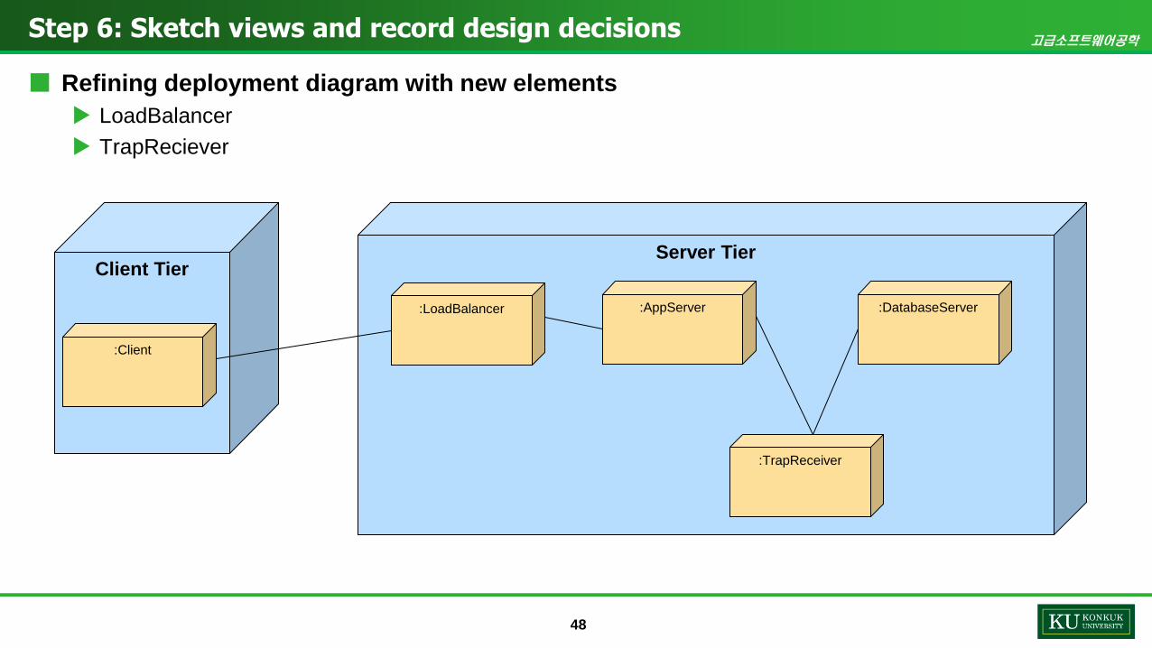
Step 6: Sketch views and record design decisions
■ Refining deployment diagram with new elements
LoadBalancer
TrapReciever
Client TierServer Tier
:Client
:LoadBalancer :AppServer :DatabaseServer
:TrapReceiver

고급소프트웨어공학
49
Step 6: Sketch views and record design decisions
■ Sequence Diagram for UC-4: Manage network
Illustrating how the TrapReceiver element exchanges messages with other elements to support UC-4
(Manage network)
:NetworkDevice :TrapReceiver :UserWorkStation:ApplicationServer
consume()
Trap()
transformAndEnqueue(Event)
event()
consume()
updateView()

고급소프트웨어공학
50
Step 7: Perform analysis of current design and review iteration goal and achievement of design purpose
Not Addressed Partially Addressed Completely Addressed Design Decisions Made During the Iteration
UC-1
UC-2
UC-3
UC-4
UC-5
QA-1
QA-2
QA-3 Tactic 채택을 통해부분 고려되었음
QA-4 Tactic 채택을 통해부분 고려되었음
QA-5 Important QA 로선택되어 Tactic, queue, framework 를 통해 고려완료
QA-6
CRN-1
CRN-2 ADD iteration 을끝냄으로써 고려 완료
CRN-3
CRN-4
CRN-5
CRN-6
CON-1
CON-2
CON-3

고급소프트웨어공학
51
THANK YOU FOR YOUR ATTENTION!