Embed Size (px)
Citation preview
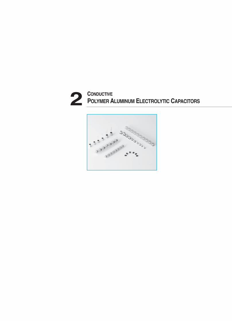
POLYMER ALUMINUM ELECTROLYTIC CAPACITORS 2 CONDUCTIVE
2013-2장 2012.11.22 5:30 PM 페이지29 G4-1.25G(Mac 1) JETPDF 2400DPI 175LPI T
30
CONDUCTIVE POLYMER ALUMINUM ELECTROLYTIC CAPACITORS
Hi-CAP (Conductive Polymer Aluminum Electrolytic Capacitor)
Hi-CAP is an electrolytic capacitor that uses a highly electric conductive polymer as it’s electrolyte.Hi-CAP has excellent temperature and load life characteristics due to adoption of stable polymer in high temperature.Compared to other electrolytic capacitors, the Hi-CAP is a low impedance capacitor suitable for high frequency makingit ideal for digital circuit.
1. Circuit design
(1) The conducting polymer capacitor cannot be used in circuits that undergo frequent charging and dischargingbecause the resulting internal heat buildup can cause capacitor failure.
(2) Do not use the capacitor in time-constant or coupling circuits. In these type of circuit, electrical characteristics suchas capacitance can change under certain environmental conditions.
2. Capacitor handling techniques
(1) Capacitor insertionIncorrect land size may cause problems with capacitor placement and mountability.Refer to the land size table for appropriate design dimensions.
(2) SolderingWhen using a soldering iron, set the tip temperature to no more than 300°C, and work in as short a time as possibleunder 10 seconds. While soldering, do not apply strong force to the capacitor.
Reflow solderingThe conducting polymer capacitor is designed specifically for reflow soldering.Maintain soldering conditions (pre-heating, reflow temperature, time) within the range indicated in the productspecifications. If soldering time is lengthened or temperature is higher, the heat can damage the capacitor elementand / or the molded case.Do not perform reflow soldering more than twice.
(3) Circuit board cleaningCapacitors can withstand immersion in solvent at 60°C or under for up to 5 minutes.Be sure to sufficiently wash (about 3 min. with water) and dry (20 min. at 100°C) the board afterward.
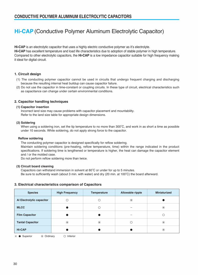
3. Electrical characteristics comparison of Capacitors
Species
Al Electrolytic capacitor
MLCC
Film Capacitor
Tantal Capacitor
Hi-CAP
High Frequency
⊙
Temperature
⊙
Allowable ripple
⊙
-
-
Miniaturized
⊙
⊙
⊙
※ Superior ⊙ Ordinary Inferior
2013-2장 2012.11.22 5:30 PM 페이지30 G4-1.25G(Mac 1) JETPDF 2400DPI 175LPI T
31
CONDUCTIVE POLYMER ALUMINUM ELECTROLYTIC CAPACITORS
SO
LID TY
PE
S
PRECAUTIONS AND GUIDELINES (Conductive Polymer)
The Hi-CAP is a Conductive Polymer Solid Aluminum Capacitor that uses highly conductive polymer electrolyticmaterial.Please read the following in order to get the most out of your Hi-CAP capacitor. For aluminum electrolytic capacitors,please refer to PRECAUTIONS AND GUIDELINES
1. Designing Device Circuits
1) Types of Circuits Where Hi-CAP Capacitors are Not to be UsedThe leakage current in conductive polymer solid aluminum capacitors(hereafter called Hi-CAP) may vary dependingon thermal stresses during soldering. Avoid the use of capacitors in the following types of circuits:
① High-impedance circuits that are to sustain voltages.② Coupling circuits③ Time constant circuits
Because the capacitance varies depending on the environment the capacitors are used in, there is a possibilitythat the capacitor can affect a time constant circuit where sensitivity to variation in capacitance is required.
④ Other circuits that are significantly affected by leakage current
2) Circuit DesignVerify the following before designing the circuit:
① The electrical characteristics of the capacitor will vary depending on differences in temperature and frequency. You had better design after verifying the scope of these factors.
② When connecting two or more capacitors in parallel, ensure that the design takes current balancing into account.③ When two or more capacitors are connected in series, variability in applied voltage may cause over-voltage
conditions. Contact Samwha before using capacitors connected in series.④ Avoid putting heat generating parts either around the capacitor or on the reverse of the circuit board
3) Use in High Reliable and Critical ApplicationsConsult with Samwha before using these capacitors in applications involving human life: Aviation/space equipment,Nuclear power equipment, Medical equipment and Automotive equipment, or in applications where capacitor failurecould have a major impact
4) PolarityThe Hi-CAP is a polarized solid aluminum electrolytic capacitor. Do not apply either reverse voltages or AC voltagesto the polarized capacitors, using reversed polarity may cause a short circuit. Refer to the catalog productspecifications or capacitor body to confirm the polarity prior to use
5) Operating VoltageDo not apply a greater than rated voltage, if a voltage greater than the rated voltage is suddenly applied the leakagecurrent increases causing shorting. The peak voltage of superimposed AC voltages(ripple voltages) on DC voltagesmust not exceed the full rated voltage. While there are specifications for surge voltages exceeding the ratedvoltage, usage conditions apply, and continued operation for extended periods of time under such conditions cannotbe guaranteed.
6) Ripple currentDo not apply currents in excess of the rated ripple current. The superimposition of a large ripple current increasesthe rate of heating within the capacitor. When excessive ripple current is imposed the internal temperatureincreases which can shorten life and shorting may occur.
2013-2장 2012.11.22 5:30 PM 페이지31 G4-1.25G(Mac 1) JETPDF 2400DPI 175LPI T
32
CONDUCTIVE POLYMER ALUMINUM ELECTROLYTIC CAPACITORS
7) Operating temperatureUse within the stated category temperature range, if used outside this range, characteristics can deterioratepotentially leading to problems.
8) Charging and Discharging in CapacitorDo not use the Hi-CAP in circuits where the capacitor is repetitively charged and discharged rapidly. Repetitivelycharging and discharging the capacitor rapidly may reduce the capacitance or may cause damage due to internalheating. Use of a protective circuit to ensure reliability is recommended when rush currents exceed 20A.
9) Leakage currentThe leakage current may increase when the capacitors are subjected to the conditions below. After that, however,the leakage current will gradually decrease by self-healing action of the dielectric oxide layer when the capacitorsare applied with a voltage less than the rated voltage within the Category Temperature range. As the voltage iscloser to the rated voltage and the temperature is closer to the upper limit of Category Temperature range, theleakage current decreases faster. The leakage current will increase by the following factors,
① Soldering② Testing of high temperature exposure with no voltage applied, high temperature/humidity storage, temperature
cycles, etc.
10) Failures and Service LifeBased on the KS C 6032 Standard, the failure rate for Hi-CAP(with a 60% reliability standard) is as follows:0.5%/1,000 hours(applied the rate voltage at the upper limit of Category Temperature range)
(1) Failure Modes
① The principal failure mode is wear-out failure, that is, capacitance decreases and ESR increases, and eventuallythe capacitors become open circuit failure. In addition, short circuit failure may happen with over-voltage andexcessive current applied to the capacitors.
② The failure rate would be reduced by reducing ambient temperatures, ripple current and applying voltage.③ If the short-circuited capacitor, which may be caused by over-voltages higher than the rated voltage or other
conditions, has a large amount of current passed through, the aluminum can of the capacitor bulges and mightbe expelled with odor gas emitted.
④ The product contains flammable materials. If the short causes a spark it may ignite. Please be careful wheninstalling the product, its position and the layout design.
Increase safety by using in conjunction with a protective circuit or protective equipment. Install measures such as redundant circuits so that the failure of a part of the equipment will not cause unstable
operation.
(2) Service LifeHi-CAP uses rubber as the sealing material, so the service life depends on the thermal integrity of this rubber.Consequently, it is recommended to use the capacitor at a lower temperature than the maximum temperature forthe capacitor category.
11) Capacitor InsulationInsulation of the capacitor's case is not guaranteed. Ensure electrical insulation between the capacitor case,negative electrode, positive electrode and circuit pattern.
12) Capacitor Usage EnvironmentDo not use/expose capacitors to the following conditions.
① Oil, water, salty water, take care to avoid storage in damp locations.② Direct sunlight③ Toxic gases such as hydrogen, sulfide, sulfurous acids, nitrous acids, chlorine and chlorine compounds, bromine
and bromine compounds, ammonia, etc.④ Ozone, ultraviolet rays and radiation.
2013-2장 2012.11.22 5:30 PM 페이지32 G4-1.25G(Mac 1) JETPDF 2400DPI 175LPI T
33
CONDUCTIVE POLYMER ALUMINUM ELECTROLYTIC CAPACITORS
SO
LID TY
PE
S
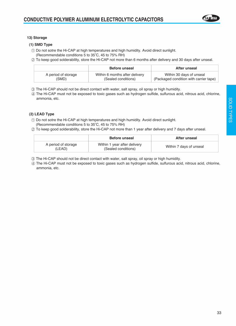
13) Storage
(1) SMD Type
① Do not sotre the Hi-CAP at high temperatures and high humidity. Avoid direct sunlight.(Recommendable conditions 5 to 35°C, 45 to 75% RH)
② To keep good solderability, store the Hi-CAP not more than 6 months after delivery and 30 days after unseal.
③ The Hi-CAP should not be direct contact with water, salt spray, oil spray or high humidity.④ The Hi-CAP must not be exposed to toxic gases such as hydrogen sulfide, sulfurous acid, nitrous acid, chlorine,
ammonia, etc.
(2) LEAD Type
① Do not sotre the Hi-CAP at high temperatures and high humidity. Avoid direct sunlight.(Recommendable conditions 5 to 35°C, 45 to 75% RH)
② To keep good solderability, store the Hi-CAP not more than 1 year after delivery and 7 days after unseal.
③ The Hi-CAP should not be direct contact with water, salt spray, oil spray or high humidity.④ The Hi-CAP must not be exposed to toxic gases such as hydrogen sulfide, sulfurous acid, nitrous acid, chlorine,
ammonia, etc.
Before unseal
Within 6 months after delivery(Sealed conditions)
A period of storage(SMD)
Within 30 days of unseal(Packaged condition with carrier tape)
After unseal
Before unseal
Within 1 year after delivery(Sealed conditions)
A period of storage(LEAD)
Within 7 days of unseal
After unseal
2013-2장 2012.11.22 5:30 PM 페이지33 G4-1.25G(Mac 1) JETPDF 2400DPI 175LPI T
34
CONDUCTIVE POLYMER ALUMINUM ELECTROLYTIC CAPACITORS
BULK PACKING QUANTITY(PCS) / BOX
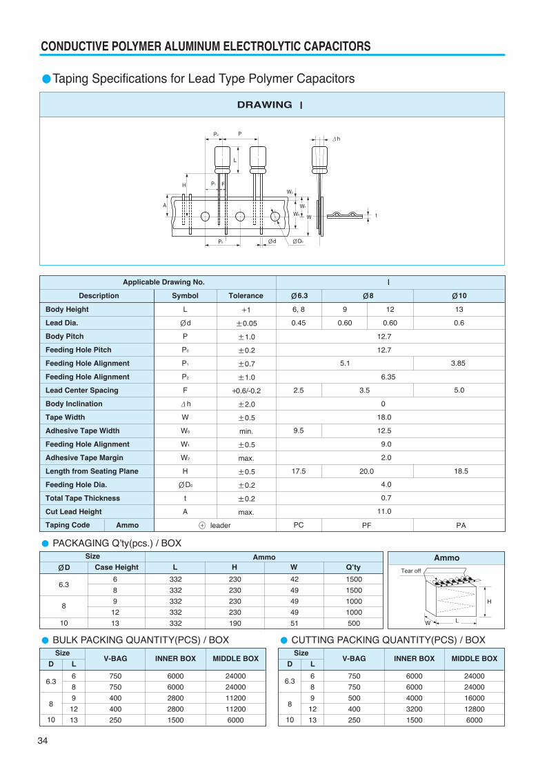
Taping Specifications for Lead Type Polymer Capacitors
DRAWING Ⅰ
Body Height
Lead Dia.
Body Pitch
Feeding Hole Pitch
Feeding Hole Alignment
Feeding Hole Alignment
Lead Center Spacing
Body Inclination
Tape Width
Adhesive Tape Width
Feeding Hole Alignment
Adhesive Tape Margin
Length from Seating Plane
Feeding Hole Dia.
Total Tape Thickness
Cut Lead Height
Taping Code
L
Ød
P
P0
P1
P2
F
Δh
W
W0
W1
W2
H
ØD0
t
A
+1
±0.05
±1.0
±0.2
±0.7
±1.0
+0.6/-0.2
±2.0
±0.5
min.
±0.5
max.
±0.5
±0.2
±0.2
max.
12
0.60
9
0.60
13
0.6
6, 8
0.45
2.5
17.5
9.5
PC
20.0
PF
18.5
PA
3.5 5.0
3.855.1
12.7
12.7
6.35
0
18.0
12.5
9.0
2.0
4.0
0.7
11.0
Applicable Drawing No.
Description Symbol Tolerance Ø6.3 Ø8
Ⅰ
Ø10
Ammo leader+
SizeV-BAG INNER BOX MIDDLE BOX
D
6.36
8
9
12
13
750
750
400
400
250
6000
6000
2800
2800
1500
24000
24000
11200
11200
6000
8
10
L
PACKAGING Q’ty(pcs.) / BOXSize Ammo
ØD
6.36
8
9
12
13
332
332
332
332
332
230
230
230
230
190
42
49
49
49
51
1500
1500
1000
1000
500
8
10
Case Height L H W Q’ty
CUTTING PACKING QUANTITY(PCS) / BOXSize
V-BAG INNER BOX MIDDLE BOXD
6.36
8
9
12
13
750
750
500
400
250
6000
6000
4000
3200
1500
24000
24000
16000
12800
6000
8
10
L
ØD0ØdP0
F
L
PP2
W2
t
Δh
P1
A
H
W0
W1
W
Ammo
H
L
Tear off
W
2013-2장 2012.11.22 5:30 PM 페이지34 G4-1.25G(Mac 1) JETPDF 2400DPI 175LPI T
35
CONDUCTIVE POLYMER ALUMINUM ELECTROLYTIC CAPACITORS
SO
LID TY
PE
S
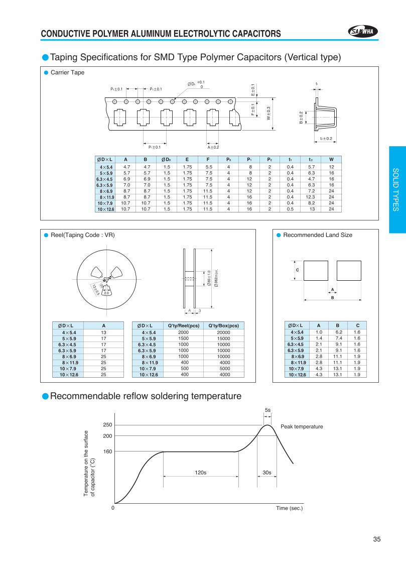
Carrier Tape
Taping Specifications for SMD Type Polymer Capacitors (Vertical type)
ØD×L A B ØD0 E F P0 P1 P2 t1 t 2 W
4×5.45×5.9
6.3×4.56.3×5.9
8×6.98×11.9
10×7.910×12.6
4.75.76.97.08.78.7
10.710.7
4.75.76.97.08.78.7
10.710.7
1.51.51.51.51.51.51.51.5
1.751.751.751.751.751.751.751.75
5.57.57.57.5
11.511.511.511.5
44444444
88
121212161616
22222222
0.40.40.40.40.40.40.40.5
5.76.34.76.37.2
12.38.213
1216161624242424
Recommended Land Size Reel(Taping Code : VR)
ØD×L A 4×5.45×5.9
6.3×4.56.3×5.9
8×6.98×11.9
10×7.910×12.6
1317171725252525
ØD×L Q’ty/Reel(pcs) Q’ty/Box(pcs) 4×5.45×5.9
6.3×4.56.3×5.9
8×6.98×11.9
10×7.910×12.6
20001500100010001000
400500400
2000015000100001000010000400050004000
Recommendable reflow soldering temperature
250
200
160
0 Time (sec.)
Peak temperature
30s120s
5s
Tem
pera
ture
on
the
surf
ace
of c
apac
itor
(°C
)
2.0
2313±0.5
Ø80
±1.
0
A 3
Ø38
2max.
ØD×L A B C4×5.45×5.9
6.3×4.56.3×5.9
8×6.98×11.9
10×7.910×12.6
1.01.42.12.12.82.84.34.3
6.27.49.19.1
11.111.113.113.1
1.61.61.61.61.91.91.91.9
C
A
B
t2±0.2
t1
B±
0.2
W±
0.3
F±
0.1
E±
0.1
P2±0.1ØD0
+0.10
P0±0.1
A±0.2P1±0.1
2013-2장 2012.11.22 5:30 PM 페이지35 G4-1.25G(Mac 1) JETPDF 2400DPI 175LPI T
36
CONDUCTIVE POLYMER ALUMINUM ELECTROLYTIC CAPACITORS
Taping Specifications for SMD type Polymer Capacitors (Horizontal type)
Carrier Tape
Packaging Specifications
A B ØD0 ØD1 E F P0 P1 P2 t1 t2 WSize code
4.7 7.7 1.5 1.6 1.75 5.5 4.0 8.0 2.0 0.3 2.2 12.0
4.7 7.7 1.5 1.6 1.75 5.5 4.0 8.0 2.0 0.3 3.4 12.0
4.7 7.7 1.5 1.6 1.75 5.5 4.0 8.0 2.0 0.3 4.5 12.0
A
C
D
ØC ØD E W t
13.0 21.0 2.0 14.0 2.0
80 m
in.
330±
2.0
t±0.5
W±1.5
ØD±0.8
ØC±0.5
E±0.5
Chip component
B±
0.2
Feeding hole
ØD0
A±0.2
Chip pocket
E±
0.1
W±
0.3
F±
0.1
ØD1±0.1P1±0.1
t2±0.2
t1
P0±0.1
P2±0.1
+0.10
Q’ty / ReelSize code
3000 pcs.
2000 pcs.
2000 pcs.
A
C
D
2013-2장 2012.11.22 5:30 PM 페이지36 G4-1.25G(Mac 1) JETPDF 2400DPI 175LPI T
37
CONDUCTIVE POLYMER ALUMINUM ELECTROLYTIC CAPACITORS
SO
LID TY
PE
S
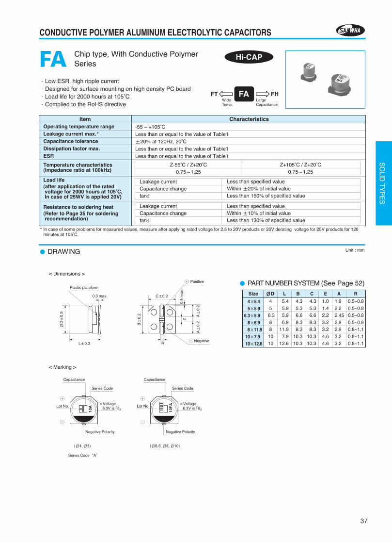
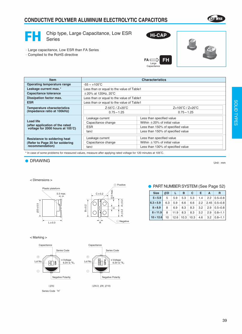
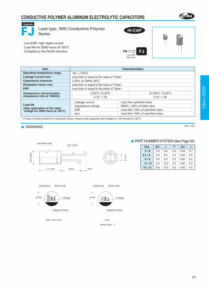
·Low ESR, high ripple current·Designed for surface mounting on high density PC board·Load life for 2000 hours at 105°C·Complied to the RoHS directive
DRAWING Unit : mm
Chip type, With Conductive PolymerSeriesFA
Item CharacteristicsOperating temperature rangeLeakage current max.Capacitance toleranceDissipation factor max.ESR
Temperature characteristics(Impedance ratio at 100kHz)
Load life(after application of the ratedvoltage for 2000 hours at 105°C,In case of 25WV is applied 20V)
Resistance to soldering heat(Refer to Page 35 for solderingrecommendation)
-55 ~ +105°CLess than or equal to the value of Table1±20% at 120Hz, 20°CLess than or equal to the value of Table1Less than or equal to the value of Table1
Leakage currentCapacitance changetanδ
Less than specified valueWithin ±20% of initial valueLess than 150% of specified value
Leakage currentCapacitance changetanδ
Less than specified valueWithin ±10% of initial valueLess than 130% of specified value
Z-55°C / Z+20°C0.75 ~ 1.25
Z+105°C / Z+20°C0.75 ~ 1.25
Hi-CAP
In case of some problems for measured values, measure after applying rated voltage for 2.5 to 20V products or 20V derating voltage for 25V products for 120 minutes at 105°C.
PART NUMBER SYSTEM (See Page 52)
4
5
6.3
8
8
10
10
5.4
5.9
5.9
6.9
11.9
7.9
12.6
4.3
5.3
6.6
8.3
8.3
10.3
10.3
4.3
5.3
6.6
8.3
8.3
10.3
10.3
1.0
1.4
2.2
3.2
3.2
4.6
4.6
1.9
2.2
2.45
2.9
2.9
3.2
3.2
0.5~0.8
0.5~0.8
0.5~0.8
0.5~0.8
0.8~1.1
0.8~1.1
0.8~1.1
4×5.45×5.9
6.3×5.98×6.98×11.9
10×7.910×12.6
Size ØD L B C E A R
L±0.3
C±0.2
E
A±
0.2
A±
0.2
R
ØD±
0.5
0.3 max.
0.5
max
.
Negative
+
-
Positive
Plastic plateform
< Dimensions >
< Marking >
(Ø4,Ø5)
Series Code“A”
(Ø6.3,Ø8,Ø10)
B±
0.2
Negative Polarity
Lot No.
Series Code
Capacitance
+
-
10A
※Voltage6.3V is 6
Negative Polarity
Lot No.
Series Code
Capacitance
+
-
10F
A ※Voltage6.3V is 6
2013-2장 2012.11.22 5:30 PM 페이지37 G4-1.25G(Mac 1) JETPDF 2400DPI 175LPI T
38
CONDUCTIVE POLYMER ALUMINUM ELECTROLYTIC CAPACITORS
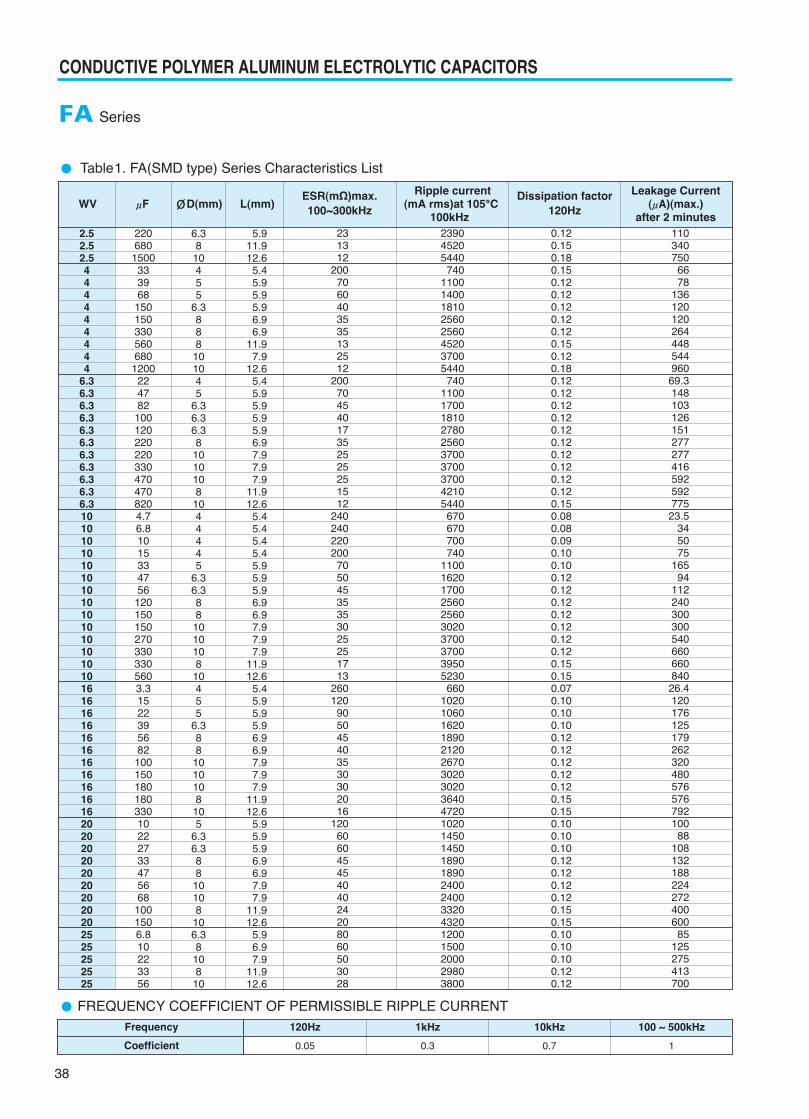
Table1. FA(SMD type) Series Characteristics List
FA Series
2.52.52.5444444444
6.36.36.36.36.36.36.36.36.36.36.3101010101010101010101010101016161616161616161616162020202020202020202525252525
6.3810455
6.3888101045
6.36.36.3810101081044445
6.36.388101010810455
6.3881010108105
6.36.38810108106.3810810
5.911.912.6
5.45.95.95.96.96.9
11.97.9
12.65.45.95.95.95.96.97.97.97.9
11.912.6
5.45.45.45.45.95.95.96.96.97.97.97.9
11.912.6
5.45.95.95.96.96.97.97.97.9
11.912.6
5.95.95.96.96.97.97.9
11.912.6
5.96.97.9
11.912.6
2206801500
333968
1501503305606801200
224782
1001202202203304704708204.76.81015334756
1201501502703303305603.31522395682
10015018018033010222733475668
1001506.810223356
231312
2007060403535132512
20070454017352525251512
240240220200
70504535353025251713
260120
905045403530302016
12060604545404024208060503028
239045205440
74011001400181025602560452037005440
7401100170018102780256037003700370042105440
670670700740
1100162017002560256030203700370039505230
660102010601620189021202670302030203640472010201450145018901890240024003320432012001500200029803800
0.120.150.180.150.120.120.120.120.120.150.120.180.120.120.120.120.120.120.120.120.120.120.150.080.080.090.100.100.120.120.120.120.120.120.120.150.150.070.100.100.100.120.120.120.120.120.150.150.100.100.100.120.120.120.120.150.150.100.100.100.120.12
110340750
6678
13612012026444854496069.314810312615127727741659259277523.5
345075
16594
11224030030054066066084026.4120176125179262320480576576792100
88108132188224272400600
85125275413700
Ripple current Leakage CurrentWV μF ØD(mm) L(mm) (mA rms)at 105°C (μA)(max.)
100kHz after 2 minutes
ESR(mΩ)max.100~300kHz
Dissipation factor120Hz
FREQUENCY COEFFICIENT OF PERMISSIBLE RIPPLE CURRENTFrequency
Coefficient
120Hz
0.05
1kHz
0.3
100 ~ 500kHz
1
10kHz
0.7
2013-2장 2012.11.22 5:30 PM 페이지38 G4-1.25G(Mac 1) JETPDF 2400DPI 175LPI T
39
CONDUCTIVE POLYMER ALUMINUM ELECTROLYTIC CAPACITORS
SO
LID TY
PE
S
·Large capacitance, Low ESR than FA Series·Complied to the RoHS directive
DRAWING Unit : mm
PART NUMBER SYSTEM (See Page 52)
Chip type, Large Capacitance, Low ESRSeriesFH
Item CharacteristicsOperating temperature rangeLeakage current max.Capacitance toleranceDissipation factor max.ESR
Temperature characteristics(Impedance ratio at 100kHz)
Load life(after application of the ratedvoltage for 2000 hours at 105°C)
Resistance to soldering heat(Refer to Page 35 for solderingrecommendation)
-55 ~ +105°CLess than or equal to the value of Table1±20% at 120Hz, 20°CLess than or equal to the value of Table1Less than or equal to the value of Table1
Leakage currentCapacitance changeESRtanδ
Less than specified valueWithin ±20% of initial valueLess than 150% of specified valueLess than 150% of specified value
Leakage currentCapacitance changetanδ
Less than specified valueWithin ±10% of initial valueLess than 130% of specified value
Z-55°C / Z+20°C0.75 ~ 1.25
Z+105°C / Z+20°C0.75 ~ 1.25
5
6.3
8
8
10
5.9
5.9
6.9
11.9
12.6
5.3
6.6
8.3
8.3
10.3
5.3
6.6
8.3
8.3
10.3
1.4
2.2
3.2
3.2
4.6
2.2
2.45
2.9
2.9
3.2
0.5~0.8
0.5~0.8
0.5~0.8
0.8~1.1
0.8~1.1
5×5.9
6.3×5.9
8×6.9
8×11.9
10×12.6
Size ØD L B C E A R
In case of some problems for measured values, measure after applying rated voltage for 120 minutes at 105°C.
Hi-CAP
< Dimensions >
< Marking >
L±0.3
C±0.2
E
A±
0.2
A±
0.2
R
ØD±
0.5
0.3 max.
0.5
max
.
Negative
+
-
Positive
Plastic plateform
(Ø5)
Series Code“H”
(Ø6.3,Ø8,Ø10)
B±
0.2
Negative Polarity
Lot No.
Series Code
Capacitance
+
-
10H
※Voltage6.3V is 6
Negative Polarity
Lot No.
Series Code
Capacitance
+
-
10F
H ※Voltage6.3V is 6
2013-2장 2012.11.22 5:30 PM 페이지39 G4-1.25G(Mac 1) JETPDF 2400DPI 175LPI T
40
CONDUCTIVE POLYMER ALUMINUM ELECTROLYTIC CAPACITORS
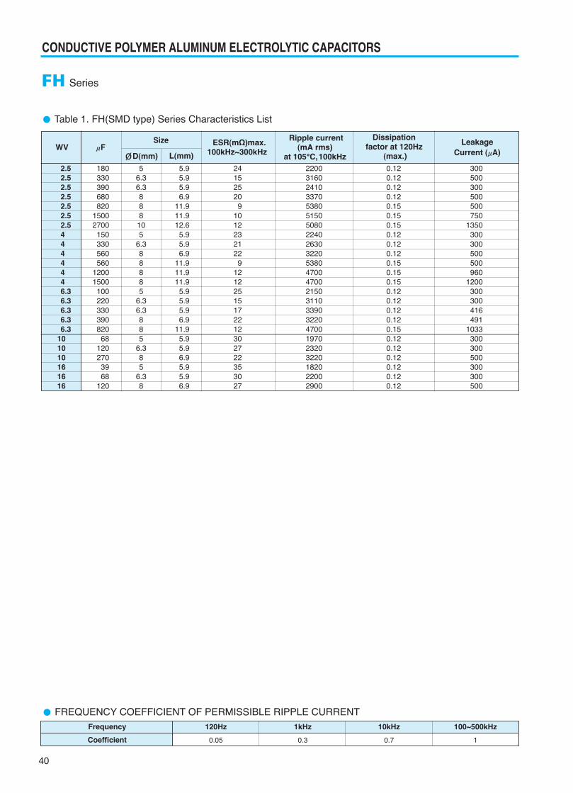
Table 1. FH(SMD type) Series Characteristics List
FH Series
2.5 2.52.52.52.52.52.54444446.36.36.36.36.3
101010 161616
180330390680820
15002700150330560560
12001500100220330390820
68120270
3968
120
56.36.3888
105
6.388885
6.36.3885
6.385
6.38
5.95.95.96.9
11.911.912.6
5.95.96.9
11.911.911.9
5.95.95.96.9
11.95.95.96.95.95.96.9
24152520
91012232122
912122515172212302722353027
220031602410337053805150508022402630322053804700470021503110339032204700197023203220182022002900
0.120.120.120.120.150.150.150.120.120.120.150.150.150.120.120.120.120.150.120.120.120.120.120.12
300500300500500750
1350300300500500960
1200300300416491
1033300300500300300500
ESR(mΩ)max. Ripple currentWV μF 100kHz~300kHz (mA rms)
at 105°C,100kHz
Dissipation factor at 120Hz
(max.)
Size
ØD(mm) L(mm)
Leakage Current (μA)
FREQUENCY COEFFICIENT OF PERMISSIBLE RIPPLE CURRENTFrequency
Coefficient
120Hz
0.05
1kHz
0.3
100~500kHz
1
10kHz
0.7
2013-2장 2012.11.22 5:30 PM 페이지40 G4-1.25G(Mac 1) JETPDF 2400DPI 175LPI T
41
CONDUCTIVE POLYMER ALUMINUM ELECTROLYTIC CAPACITORS
SO
LID TY
PE
S
·The FT Series is very reliable, guaranteeing performance·Suitable for use in smoothing circuits of vehicle-mounted equipment,
industrial equipment, etc·Complied to the RoHS directive
DRAWING Unit : mm
Chip type, Guaranteed at 125°CSeriesFT
Item CharacteristicsOperating temperature rangeLeakage current max.Capacitance toleranceDissipation factor max.ESR
Temperature characteristics(Impedance ratio at 100kHz)
Load life(after application of the ratedvoltage for 2000 hours at 125°C)
Resistance to soldering heat(Refer to Page 35 for solderingrecommendation)
-55 ~ +125°CLess than or equal to the value of Table1±20% at 120Hz, 20°CLess than or equal to the value of Table1Less than or equal to the value of Table1
Leakage currentCapacitance changeESRtanδ
Less than specified valueWithin ±20% of initial valueLess than 200% of specified valueLess than 200% of specified value
Leakage currentCapacitance changetanδ
Less than specified valueWithin ±10% of initial valueLess than 130% of specified value
Z-55°C / Z+20°C0.75 ~ 1.25
Z+125°C / Z+20°C0.75 ~ 1.25
In case of some problems for measured values, measure after applying rated voltage for 120 minutes at 125°C.
Hi-CAP
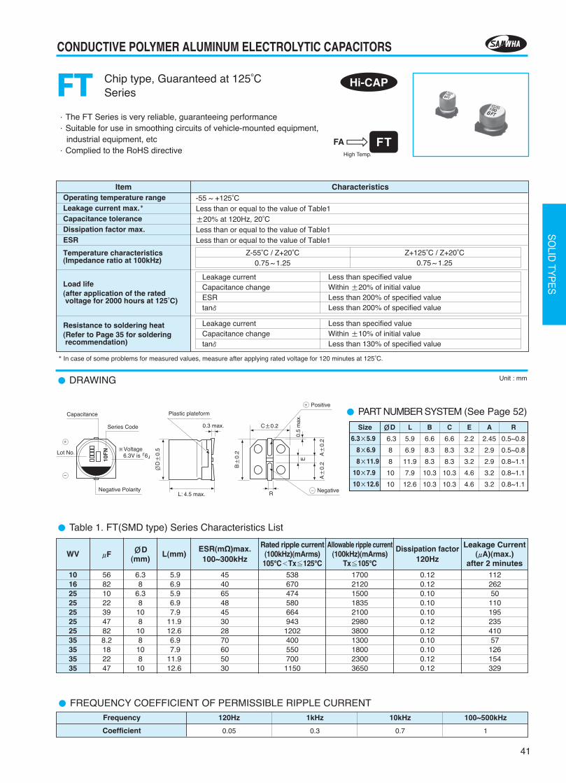
Table 1. FT(SMD type) Series Characteristics List
1016252525252535353535
568210223947828.2182247
6.38
6.38
108
108
108
10
5.96.95.96.97.9
11.912.66.97.9
11.912.6
4540654845302870605030
538670474580664943
1202400550700
1150
17002120150018352100298038001300180023003650
0.120.120.100.100.100.120.120.100.100.120.12
1122625011019523541057126154329
WV μF ØD(mm)
L(mm)ESR(mΩ)max.100~300kHz
Rated ripple current(100kHz)(mArms)105°C≺Tx≦125°C
Allowable ripple current(100kHz)(mArms)
Tx≦105°C
Dissipation factor120Hz
Leakage Current(μA)(max.)
after 2 minutes
FREQUENCY COEFFICIENT OF PERMISSIBLE RIPPLE CURRENTFrequency
Coefficient
120Hz
0.05
1kHz
0.3
100~500kHz
1
10kHz
0.7
PART NUMBER SYSTEM (See Page 52)
6.3
8
8
10
10
5.9
6.9
11.9
7.9
12.6
6.6
8.3
8.3
10.3
10.3
6.6
8.3
8.3
10.3
10.3
2.2
3.2
3.2
4.6
4.6
2.45
2.9
2.9
3.2
3.2
0.5~0.8
0.5~0.8
0.8~1.1
0.8~1.1
0.8~1.1
6.3×5.9
8×6.9
8×11.9
10×7.9
10×12.6
Size ØD L B C E A R
Negative PolarityL: 4.5 max.
C±0.2
E
A±
0.2
A±
0.2
R
ØD±
0.5
0.3 max.
0.5
max
.
Lot No.
Series Code
Capacitance
+
-
Negative
+
-
10F
N
Positive
Plastic plateform
B±
0.2※Voltage
6.3V is 6
2013-2장 2012.11.22 5:30 PM 페이지41 G4-1.25G(Mac 1) JETPDF 2400DPI 175LPI T
42
CONDUCTIVE POLYMER ALUMINUM ELECTROLYTIC CAPACITORS
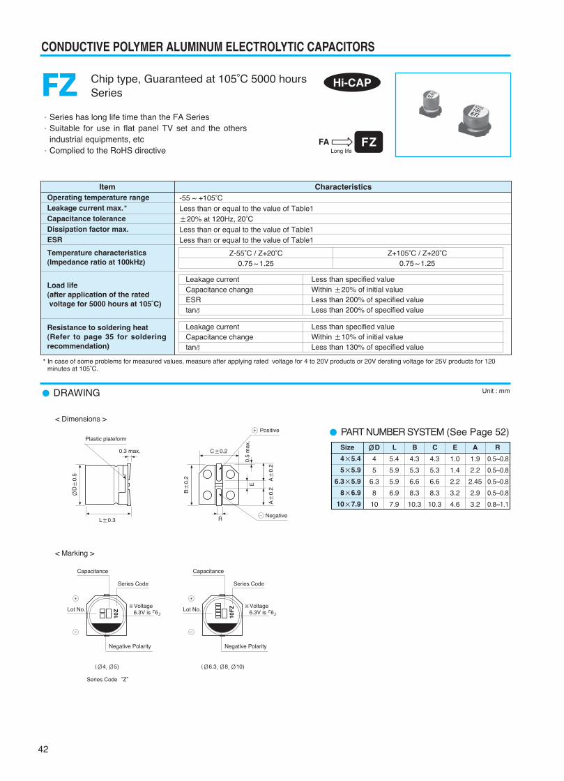
·Series has long life time than the FA Series·Suitable for use in flat panel TV set and the others
industrial equipments, etc·Complied to the RoHS directive
DRAWING
PART NUMBER SYSTEM (See Page 52)
Unit : mm
Chip type, Guaranteed at 105°C 5000 hoursSeriesFZ
Item CharacteristicsOperating temperature rangeLeakage current max.Capacitance toleranceDissipation factor max.ESR
Temperature characteristics(Impedance ratio at 100kHz)
Load life(after application of the ratedvoltage for 5000 hours at 105°C)
Resistance to soldering heat(Refer to page 35 for solderingrecommendation)
-55 ~ +105°CLess than or equal to the value of Table1±20% at 120Hz, 20°CLess than or equal to the value of Table1Less than or equal to the value of Table1
Z-55°C / Z+20°C0.75 ~ 1.25
Z+105°C / Z+20°C0.75 ~ 1.25
4×5.4
5×5.9
6.3×5.9
8×6.9
10×7.9
In case of some problems for measured values, measure after applying rated voltage for 4 to 20V products or 20V derating voltage for 25V products for 120minutes at 105°C.
Leakage currentCapacitance changeESRtanδ
Less than specified valueWithin ±20% of initial valueLess than 200% of specified valueLess than 200% of specified value
Leakage currentCapacitance changetanδ
Less than specified valueWithin ±10% of initial valueLess than 130% of specified value
Size ØD L B C E A R
4
5
6.3
8
10
5.4
5.9
5.9
6.9
7.9
4.3
5.3
6.6
8.3
10.3
4.3
5.3
6.6
8.3
10.3
1.0
1.4
2.2
3.2
4.6
1.9
2.2
2.45
2.9
3.2
0.5~0.8
0.5~0.8
0.5~0.8
0.5~0.8
0.8~1.1
Hi-CAP
L±0.3
C±0.2
E
A±
0.2
A±
0.2
R
ØD±
0.5
0.3 max.
0.5
max
.
Negative
+
-
Positive
Plastic plateform
< Dimensions >
< Marking >
(Ø4,Ø5)
Series Code“Z”
(Ø6.3,Ø8,Ø10)
B±
0.2
Negative Polarity
Lot No.
Series Code
Capacitance
+
-
10Z
※Voltage6.3V is 6
Negative Polarity
Lot No.
Series Code
Capacitance
+
-
10F
Z ※Voltage6.3V is 6
2013-2장 2012.11.22 5:30 PM 페이지42 G4-1.25G(Mac 1) JETPDF 2400DPI 175LPI T
43
CONDUCTIVE POLYMER ALUMINUM ELECTROLYTIC CAPACITORS
SO
LID TY
PE
S
Table 1. FZ(SMD type) Series Characteristics List
FZ Series
444446.36.36.36.36.3
1010101010101016161616 16202025
3368
150270680
2247
120220470
10153368
150150330
223982
100180
224710
45
6.381045
6.3810445
6.3810105
6.3810106.388
5.45.95.96.97.95.45.95.96.97.95.45.45.95.96.97.97.95.95.96.97.97.95.96.96.9
20030222220
20030222220
22020070303030249024303529604560
7401970257032204130
7401970257032204130
700740
1100220027603020377010602460276026703430145018901500
0.150.120.120.120.120.120.120.120.120.120.10.10.120.120.120.120.120.10.120.120.120.120.10.120.1
66300300500544
69.33003005005925075
16530050030066017630026232057688
188125
ESR(mΩ)max. Ripple current Leakage CurrentWV μF ØD(mm) L(mm) 100~300kHz (mA rms)at 105°C (μA)(max.)
100kHz after 2 minutes
Dissipation factor120Hz
FREQUENCY COEFFICIENT OF PERMISSIBLE RIPPLE CURRENTFrequency
Coefficient
120Hz
0.05
1kHz
0.3
100~500kHz
1
10kHz
0.7
2013-2장 2012.11.22 5:30 PM 페이지43 G4-1.25G(Mac 1) JETPDF 2400DPI 175LPI T
CONDUCTIVE POLYMER ALUMINUM ELECTROLYTIC CAPACITORS
44
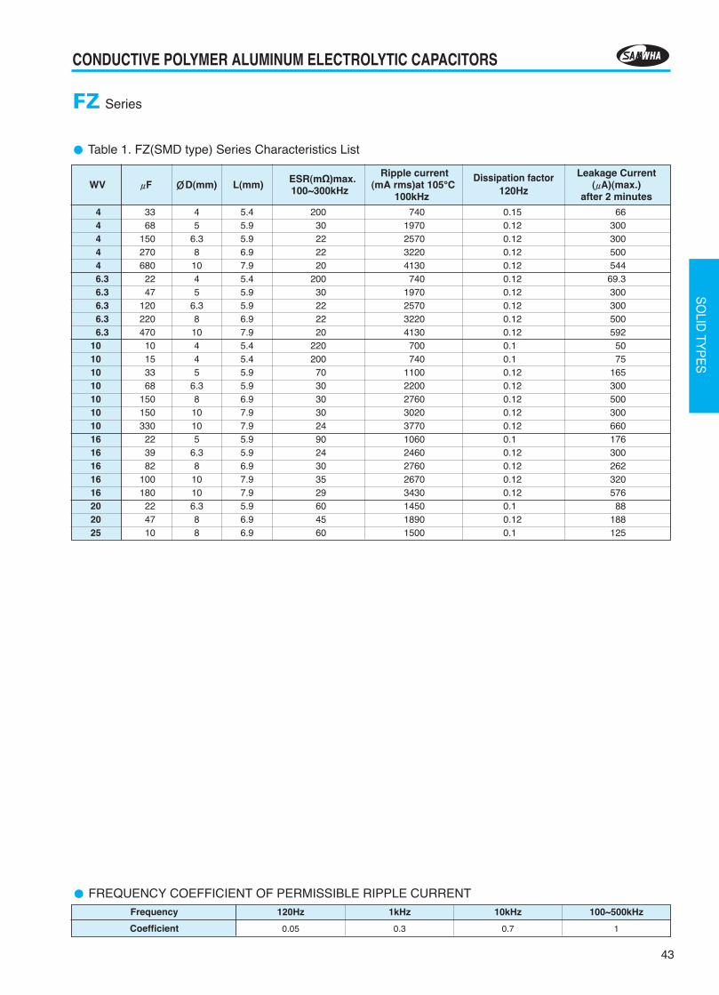
·Low ESR, high ripple current·Designed for surface mounting on Notebook PC·Complied to the RoHS directive
DRAWING Unit : mm
Chip type, Height 4.5mmLSeriesFN
Item CharacteristicsOperating temperature rangeLeakage current max.Capacitance toleranceDissipation factor max.ESR
Temperature characteristics(Impedance ratio at 100kHz)
Load life(after application of the ratedvoltage for 1000 hours at 105°C.In case 25WV is applied 20V)
Resistance to soldering heat(Refer to Page 35 for solderingrecommendation)
-55 ~ +105°CLess than or equal to the value of Table1±20% at 120Hz, 20°CLess than or equal to the value of Table1Less than or equal to the value of Table1
Leakage currentCapacitance changeESRtanδ
Less than specified valueWithin ±20% of initial valueLess than 150% of specified valueLess than 150% of specified value
Leakage currentCapacitance changetanδ
Less than specified valueWithin ±10% of initial valueLess than 130% of specified value
Z-55°C / Z+20°C0.75 ~ 1.25
Z+105°C / Z+20°C0.75 ~ 1.25
In case of some problems for measured values, measure after applying rated voltage for 120 minutes at 105°C.
Table 1. FN(SMD type) Series Characteristics List
2.546.310162025
150120100
47221515
6.36.36.36.36.36.36.3
4.54.54.54.54.54.54.5
38384041455555
1710171016701560149016501650
0.120.120.120.120.120.120.12
188240315235176150188
WV μF ØD(mm)
L(mm)ESR(mΩ)max.100~300kHz
Ripple current(mA rms) at 105°C
100kHz
Dissipationfactor 120Hz
Leakage Current(μA)(max.)
after 2 minutes
Hi-CAP
PART NUMBER SYSTEM (See Page 52)
6.3×4.5
Size ØD L B C E A R
6.3 4.5 6.6 6.6 2.2 2.45 0.5~0.8
Negative PolarityL: 4.5 max.
C±0.2
E
A±
0.2
A±
0.2
R
ØD±
0.5
0.3 max.
0.5
max
.
Lot No.
Series Code
Capacitance
+
-
Negative
+
-
10F
N
Positive
Plastic plateform
B±
0.2※Voltage
6.3V is 6
FREQUENCY COEFFICIENT OF PERMISSIBLE RIPPLE CURRENTFrequency
Coefficient
120Hz
0.05
1kHz
0.3
100~500kHz
1
10kHz
0.7
2013-2장 2012.11.22 5:30 PM 페이지44 G4-1.25G(Mac 1) JETPDF 2400DPI 175LPI T
45
CONDUCTIVE POLYMER ALUMINUM ELECTROLYTIC CAPACITORS
SO
LID TY
PE
S
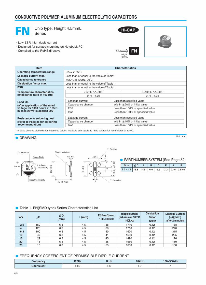
·Low ESR, high ripple current·Load life for 2000 hours at 105°C·Complied to the RoHS directive
DRAWING
Lead type, With Conductive PolymerSeriesFB
Item CharacteristicsOperating temperature rangeLeakage current max.Capacitance toleranceDissipation factor max.ESR
Temperature characteristics(Impedance ratio at 100kHz)
Load life(after application of the ratedvoltage for 2000 hours at 105°C,In case of 25WV is applied 20V)
-55 ~ +105°CLess than or equal to the value of Table1±20% at 120Hz, 20°CLess than or equal to the value of Table1Less than or equal to the value of Table1
Leakage currentCapacitance changetanδ
Less than specified valueWithin ±20% of initial valueLess than 150% of specified value
Z-55°C / Z+20°C0.75 ~ 1.25
Z+105°C / Z+20°C0.75 ~ 1.25
In case of some problems for measured values, measure the after applying rated voltage for 2.5 to 20V products or 20V derating voltage for 25V products for 120 minutes at 105°C.
Hi-CAP
Unit : mm
Laminated Case PART NUMBER SYSTEM (See Page 52)
6.3
6.3
8.0
8.0
10.0
6.0
8.0
9.0
12.0
13.0
2.5
2.5
3.5
3.5
5.0
0.45
0.45
0.60
0.60
0.60
0.5
0.5
0.5
0.5
0.5
6.3×6
6.3×8
8×9
8×12
10×13
Size ØD L P Ød β
15min. 4min.L +βmax.
P±
0.5
ØD+
0.5m
ax.
Ød ±0.05
Lot No. ※Voltage
Series Code
Negative Polarity
Capacitance
+
-
+
-
100
6FB
2013-2장 2012.11.22 5:30 PM 페이지45 G4-1.25G(Mac 1) JETPDF 2400DPI 175LPI T
CONDUCTIVE POLYMER ALUMINUM ELECTROLYTIC CAPACITORS
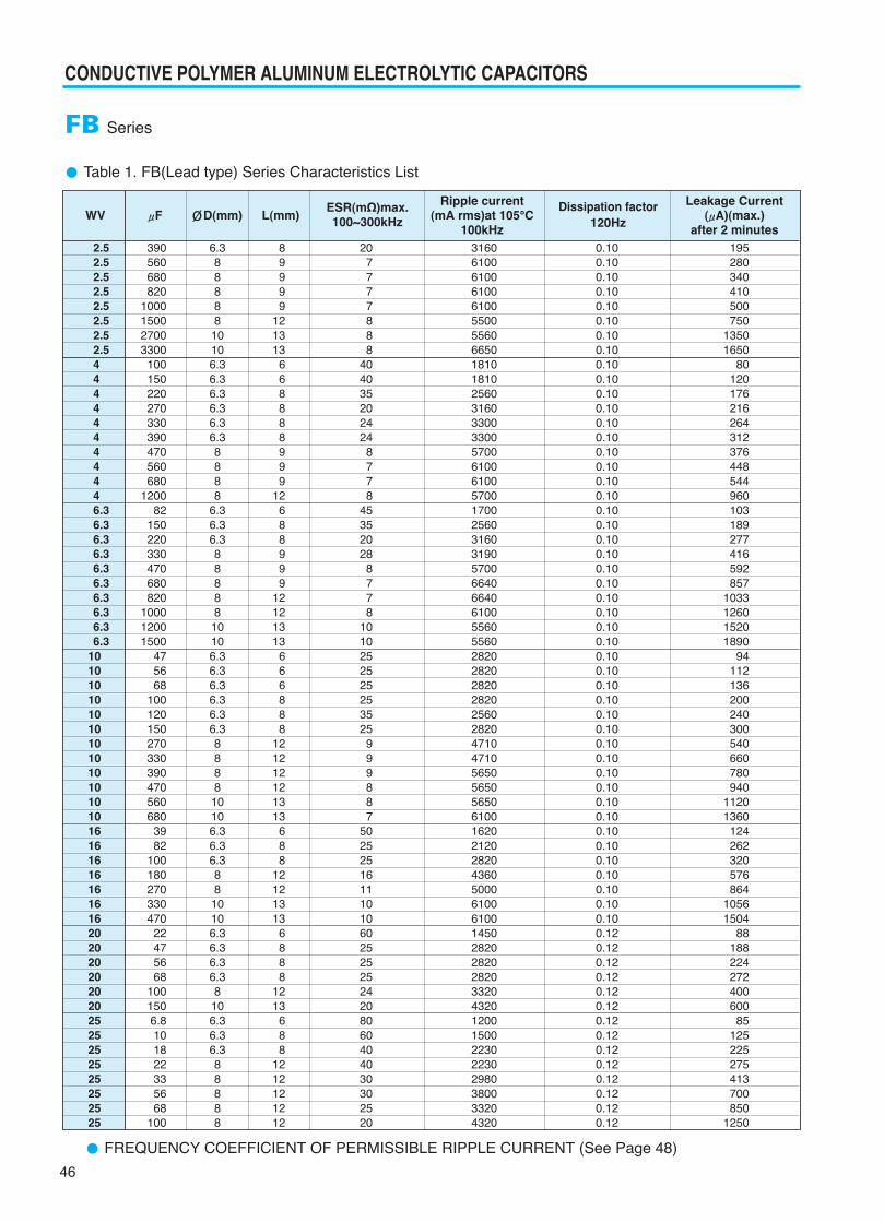
Table 1. FB(Lead type) Series Characteristics List
FB Series
2.52.52.52.52.52.52.52.544444444446.36.36.36.36.36.36.36.36.36.3
101010 1010101010101010 10161616161616162020202020202525252525252525
390560680820
1000150027003300100150220270330390470560680
120082
150220330470680820
100012001500
475668
100120150270330390470560680
3982
100180270330470
22475668
1001506.8101822335668
100
6.38888810106.36.36.36.36.36.38888
6.36.36.38888810106.36.36.36.36.36.3888810106.36.36.38810106.36.36.36.38106.36.36.388888
89999
121313
668888999
12688999
12121313
666888
121212121313
688
12121313
6888
1213
688
1212121212
207777888
404035202424
8778
45352028
8778
1010252525253525
999887
502525161110106025252524208060404030302520
3160610061006100610055005560665018101810256031603300330057006100610057001700256031603190570066406640610055605560282028202820282025602820471047105650565056506100162021202820436050006100610014502820282028203320432012001500223022302980380033204320
0.100.100.100.100.100.100.100.100.100.100.100.100.100.100.100.100.100.100.100.100.100.100.100.100.100.100.100.100.100.100.100.100.100.100.100.100.100.100.100.100.100.100.100.100.100.100.100.120.120.120.120.120.120.120.120.120.120.120.120.120.12
195280340410500750
13501650
80120176216264312376448544960103189277416592857
1033126015201890
94112136200240300540660780940
11201360
124262320576864
10561504
88188224272400600
85125225275413700850
1250
Ripple current Leakage CurrentWV μF ØD(mm) L(mm) (mA rms)at 105°C (μA)(max.)
100kHz after 2 minutes
Dissipation factor120Hz
ESR(mΩ)max.100~300kHz
FREQUENCY COEFFICIENT OF PERMISSIBLE RIPPLE CURRENT (See Page 48)
46
2013-2장 2012.11.22 5:30 PM 페이지46 G4-1.25G(Mac 1) JETPDF 2400DPI 175LPI T
47
CONDUCTIVE POLYMER ALUMINUM ELECTROLYTIC CAPACITORS
SO
LID TY
PE
S
·Low ESR, high ripple current·Load life for 2000 hours at 105°C·Complied to the RoHS directive
Lead type, With Conductive PolymerSeriesFJ
Item CharacteristicsOperating temperature rangeLeakage current max.Capacitance toleranceDissipation factor max.ESR
Temperature characteristics(Impedance ratio at 100kHz)
Load life(after application of the ratedvoltage for 2000 hours at 105°C)
-55 ~ +105°CLess than or equal to the value of Table1±20% at 120Hz, 20°CLess than or equal to the value of Table1Less than or equal to the value of Table1
Leakage currentCapacitance changeESRtanδ
Less than specified valueWithin ±20% of initial valueLess than 150% of specified valueLess than 150% of specified value
Z-55°C / Z+20°C0.75 ~ 1.25
Z+105°C / Z+20°C0.75 ~ 1.25
DRAWING Unit : mm
Hi-CAP
In case of some problems for measured values, measure after applying rated voltage for 120 minutes at 105°C.
PART NUMBER SYSTEM (See Page 52)
Upgrade
5.0
6.3
8.0
8.0
10.0
8.0
8.0
9.0
12.0
13.0
2.0
2.5
3.5
3.5
5.0
0.45
0.45
0.60
0.60
0.60
0.7
0.5
0.5
0.5
0.5
5×8
6.3×8
8×9
8×12
10×13
Size ØD L P Ød β
(Ø6.3,Ø8,Ø10)
Series Code“J”
Laminated Case
15min. 4min.L +βmax.
P±
0.5
ØD+
0.5m
ax.
Ød ±0.05
Lot No. ※Voltage
Series Code
Negative Polarity
Capacitance
+
-
+
-
560
4FJ
(Ø5)
Lot No. ※Voltage
Series Code
Negative Polarity
Capacitance
+
-
560
4J
2013-2장 2012.11.22 5:30 PM 페이지47 G4-1.25G(Mac 1) JETPDF 2400DPI 175LPI T
48
CONDUCTIVE POLYMER ALUMINUM ELECTROLYTIC CAPACITORS
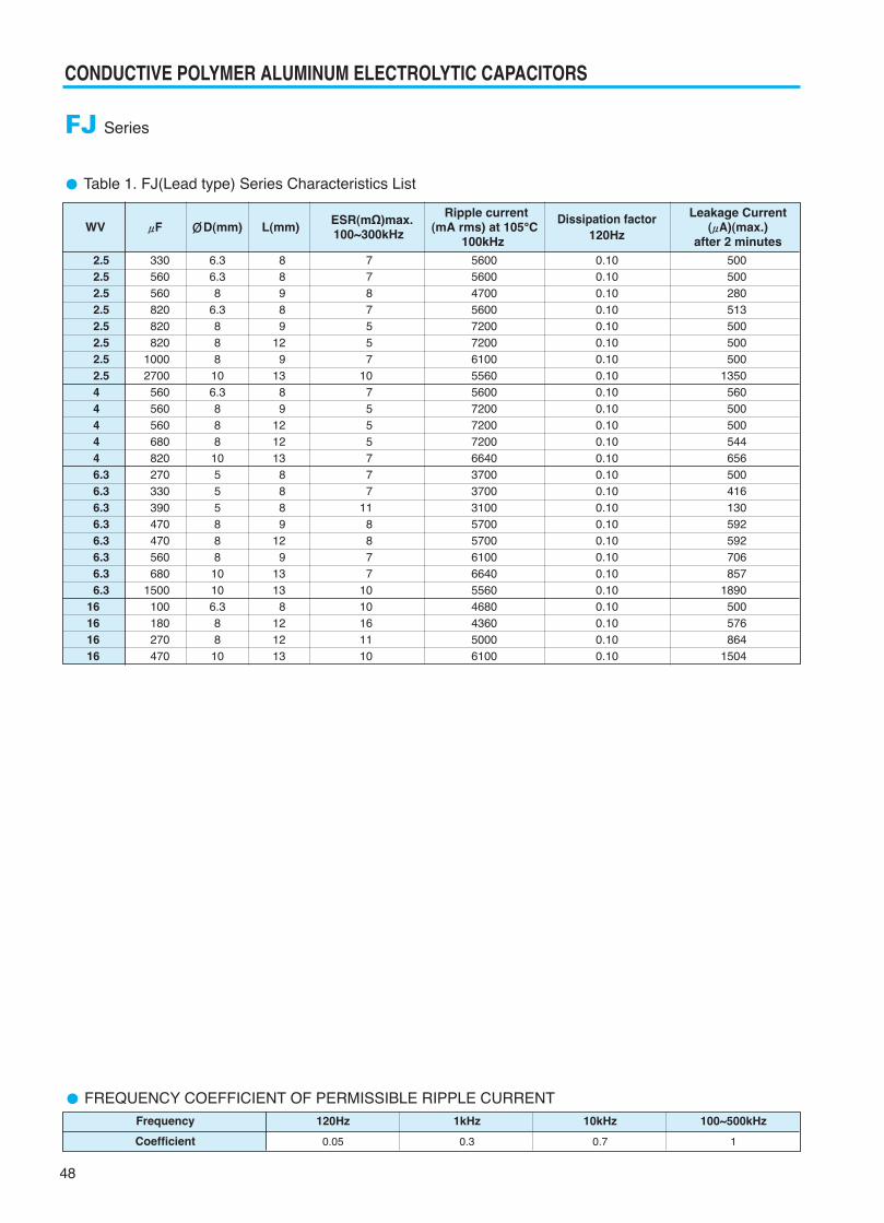
Table 1. FJ(Lead type) Series Characteristics List
FJ Series
2.52.52.52.52.5 2.52.52.54 44446.36.36.36.36.36.36.36.3
16161616
330560560820820820
10002700
560560560680820270330390470470560680
1500100180270470
6.36.38
6.3888106.38881055588810106.38810
88989
129
1389
121213
8889
129
1313
8121213
7787557
107555777
118877
1010161110
5600560047005600720072006100556056007200720072006640370037003100570057006100664055604680436050006100
0.100.100.100.100.100.100.100.100.100.100.100.100.100.100.100.100.100.100.100.100.100.100.100.100.10
500500280513500500500
1350560500500544656500416130592592706857
1890500576864
1504
ESR(mΩ)max. Ripple current Leakage CurrentWV μF ØD(mm) L(mm) 100~300kHz (mA rms) at 105°C (μA)(max.)
100kHz after 2 minutes
Dissipation factor120Hz
FREQUENCY COEFFICIENT OF PERMISSIBLE RIPPLE CURRENTFrequency
Coefficient
120Hz
0.05
1kHz
0.3
100~500kHz
1
10kHz
0.7
2013-2장 2012.11.22 5:30 PM 페이지48 G4-1.25G(Mac 1) JETPDF 2400DPI 175LPI T
49
CONDUCTIVE POLYMER ALUMINUM ELECTROLYTIC CAPACITORS
SO
LID TY
PE
S
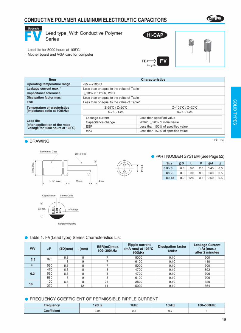
·Load life for 5000 hours at 105°C·Mother board and VGA card for computer
Lead type, With Conductive PolymerSeriesFV
Item CharacteristicsOperating temperature rangeLeakage current max.Capacitance toleranceDissipation factor max.ESR
Temperature characteristics(Impedance ratio at 100kHz)
Load life(after application of the ratedvoltage for 5000 hours at 105°C)
-55 ~ +105°CLess than or equal to the value of Table1±20% at 120Hz, 20°CLess than or equal to the value of Table1Less than or equal to the value of Table1
Leakage currentCapacitance changeESRtanδ
Less than specified valueWithin ±20% of initial valueLess than 150% of specified valueLess than 150% of specified value
Z-55°C / Z+20°C0.75 ~ 1.25
Z+105°C / Z+20°C0.75 ~ 1.25
DRAWING Unit : mm
Hi-CAP
Table 1. FV(Lead type) Series Characteristics List
2.5
4
6.3
16
820
560470560560100270
6.38
6.36.36.3
86.3
8
8988898
12
777888
2511
50006100500047004700610028205000
0.100.100.100.100.100.100.100.10
500410500592706706320864
ESR(mΩ)max. Ripple currentWV μF 100~300kHz (mA rms) at 105°C
100kHz
Dissipation factor120Hz
Leakage Current (μA) (max.)
after 2 minutesØD(mm) L(mm)
Upgrade
FREQUENCY COEFFICIENT OF PERMISSIBLE RIPPLE CURRENTFrequency
Coefficient
120Hz
0.05
1kHz
0.3
100~500kHz
1
10kHz
0.7
PART NUMBER SYSTEM (See Page 52)
6.3
8.0
8.0
8.0
9.0
12.0
2.5
3.5
3.5
0.45
0.60
0.60
0.5
0.5
0.5
6.3×8
8×9
8×12
Size ØD L P Ød β
Laminated Case
15min. 4min.L +βmax.
P±
0.5
ØD+
0.5m
ax.
Ød ±0.05
Lot No. ※Voltage
Series Code
Negative Polarity
Capacitance
+
-
+
-
560
4FV
2013-2장 2012.11.22 5:30 PM 페이지49 G4-1.25G(Mac 1) JETPDF 2400DPI 175LPI T
50
CONDUCTIVE POLYMER ALUMINUM ELECTROLYTIC CAPACITORS
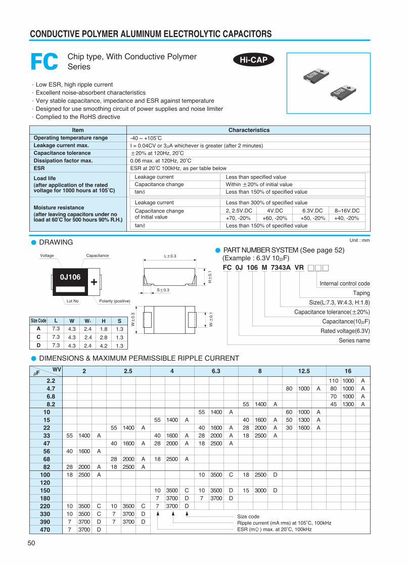
DIMENSIONS & MAXIMUM PERMISSIBLE RIPPLE CURRENT
Chip type, With Conductive PolymerSeriesFC
WVμF 2 2.5 4 6.3 8 12.5 16
2.24.76.88.2
1015223347566882
100120150180220330390470
55
40
2818
101077
A
A
AA
CCDD
1400
1600
20002500
3500350037003700
55
40
2818
1077
A
A
AA
CDD
1400
1600
20002500
350037003700
55
4028
18
1077
A
AA
A
CDD
1400
16002000
2500
350037003700
55
402818
10
107
A
AAA
C
DD
1400
160020002500
3500
35003700
55
402818
18
15
A
AAA
D
D
1400
160020002500
2500
3000
80
605030
A
AAA
1000
100013001600
110807045
AAAA
1000100010001300
Size codeRipple current (mA rms) at 105°C, 100kHzESR (mΩ) max. at 20°C, 100kHz
Hi-CAP
L7.3
7.3
7.3
Size CodeA
C
D
W1
2.4
2.4
2.4
W4.3
4.3
4.3
H1.8
2.8
4.2
S1.3
1.3
1.3
·Low ESR, high ripple current·Excellent noise-absorbent characteristics·Very stable capacitance, impedance and ESR against temperature·Designed for use smoothing circuit of power supplies and noise limiter·Complied to the RoHS directive
DRAWING PART NUMBER SYSTEM (See page 52)
Unit : mm
Item CharacteristicsOperating temperature rangeLeakage current max.Capacitance toleranceDissipation factor max.ESR
Load life(after application of the ratedvoltage for 1000 hours at 105°C)
Moisture resistance(after leaving capacitors under noload at 60°C for 500 hours 90% R.H.)
-40 ~ +105°CI = 0.04CV or 3μA whichever is greater (after 2 minutes)±20% at 120Hz, 20°C0.06 max. at 120Hz, 20°CESR at 20°C 100kHz, as per table below
Leakage currentCapacitance changetanδ
Less than specified valueWithin ±20% of initial valueLess than 150% of specified value
Leakage current
Capacitance changeof lnitial value
tanδ
Less than 300% of specified value
2, 2.5V.DC 4V.DC 6.3V.DC 8~16V.DC+70, -20% +60, -20% +50, -20% +40, -20%Less than 150% of specified value
0J106 +
Capacitance
Polarity (positive)
Voltage
W1 ±
0.1
W±
0.3
H±
0.1
S±0.3
L±0.3
FC 0J 106 M 7343A VR
Internal control code
Taping
Size(L:7.3, W:4.3, H:1.8)
Capacitance tolerance(±20%)
Capacitance(10μF)
Rated voltage(6.3V)
Series name
(Example : 6.3V 10μF)
Lot No
2013-2장 2012.11.22 5:30 PM 페이지50 G4-1.25G(Mac 1) JETPDF 2400DPI 175LPI T