Embed Size (px)
Citation preview
2 English
2.1 General 302.1.1 About this manual 302.1.2 Symbols Used 302.1.3 Abbreviations used 30
2.2 Safety 312.2.1 You should pay attention to this 312.2.2 Use as directed 332.2.3 Prohibited use 332.2.4 Handling 34
2.3 Package 362.3.1 Delivery package 362.3.2 Nameplate 362.3.3Model number description 37
2.4 Technical Description 402.4.1 General technical data 402.4.2 Standard features 402.4.3 Shaft seal 422.4.4Wiring technology 422.4.5 Holding brake 432.4.6 Fan for AKM7 432.4.7Washdown andWashdown Food 44
2.5 Mechanical Installation 472.5.1 Important Notes 47
2.6 Electrical Installation 482.6.1 Important notes 482.6.2 Guide for electrical installation 492.6.3 Connection of themotors with preassembled cables 49
2.7 Setup 502.7.1 Important notes 502.7.2 Guide for setup 512.7.3 Trouble Shooting 52
2.8 Definition of Terms for Technical Data 53
AKM Installation | 2 English
Kollmorgen | April 2015 29
AKM Installation | 2 English
2.1 General
2.1.1 About this manualThis manual describes the AKM series of synchronous servomotors (standard version). Themotors are operated in drive systems together with Kollmorgen servo amplifiers. Pleaseobserve the entire system documentation, consisting of:l Instructions manual for the servo amplifierl Manual Bus Communication (e.g. CANopen or EtherCAT)l Online help of the amplifier's setup softwarel Regional accessories manuall Technical description of the AKM series of motorsMore background information can be found in our "Product WIKI", available at www.wiki-koll-morgen.eu.
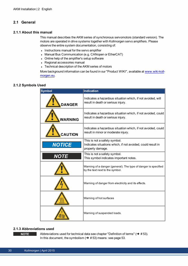
2.1.2 Symbols UsedSymbol Indication
DANGERIndicates a hazardous situation which, if not avoided, willresult in death or serious injury.
WARNINGIndicates a hazardous situation which, if not avoided, couldresult in death or serious injury.
CAUTIONIndicates a hazardous situation which, if not avoided, couldresult in minor or moderate injury.
This is not a safety symbol.Indicates situations which, if not avoided, could result inproperty damage.
This is not a safety symbol.This symbol indicates important notes.
Warning of a danger (general). The type of danger is specifiedby the text next to the symbol.
Warning of danger from electricity and its effects.
Warning of hot surfaces
Warning of suspended loads.
2.1.3 Abbreviations usedAbbreviations used for technical data see chapter "Definition of terms" (➜ # 53).In this document, the symbolism (➜ # 53) means: see page 53.
30 Kollmorgen | April 2015
2.2 SafetyThis section helps you to recognize and avoid dangers to people and objects.
2.2.1 You should pay attention to this
Specialist staff required!Only properly qualified personnel are permitted to perform such tasks as transport,assembly, setup andmaintenance. Qualified specialist staff are persons who are familiarwith the transport, installation, assembly, commissioning and operation of motors and whobring their relevant minimum qualifications to bear on their duties:l Transport :only by personnel with knowledge of handling electrostatically sensitive com-ponents.
l Mechanical Installation : only by mechanically qualified personnel.l Electrical Installation :only by electrically qualified personnel.l Setup :only by qualified personnel with extensive knowledge of electrical engineering anddrive technology
The qualified personnel must know and observe IEC 60364 / IEC 60664 and national acci-dent prevention regulations.
Read the documentation!Read the available documentation before installation and commissioning. Improper handlingof themotor can cause harm to people or damage to property. The operator must thereforeensure that all persons entrusted to work on themotor have read and understood themanualand that the safety notices in this manual are observed.
Pay attention to the technical data!Adhere to the technical data and the specifications on connection conditions (rating plate anddocumentation). If permissible voltage values or current values are exceeded, themotorscan be damaged, for example by overheating.
Perform a risk assessment!Themanufacturer of themachinemust generate a risk assessment for themachine, andtake appropriate measures to ensure that unforeseenmovements cannot cause injury or dam-age to any person or property. Additional requirements on specialist staff may also resultfrom the risk assessment.
Transport safely!Lift andmovemotors with more than 20 kg weight (AKM7 and AKM8) only with lifting tools.Lifting unassisted could result in back injury. Always observe the hints on (➜ # 34)
Secure the key!Remove any fitted key (if present) from the shaft before letting themotor run without coupledload, to avoid the dangerous results of the key being thrown out by centrifugal forces. Whendelivered, the key is protected with a plastic cap.
Hot surface!The surfaces of themotors can be very hot in operation, according to their protection cat-egory. Risk of minor burns! The surface temperature can exceed 100°C. Measure the tem-perature, and wait until themotor has cooled down below 40°C before touching it.
AKM Installation | 2 English
Kollmorgen | April 2015 31
AKM Installation | 2 English
Earthing! High voltages!It is vital that you ensure that themotor housing is safely earthed to the PE (protective earth)busbar in the switch cabinet. Risk of electric shock. Without low-resistance eart hing no per-sonal protection can be guaranteed and there is a risk of death from electric shock.Not having optical displays does not guarantee an absence of voltage. Power connectionsmay carry voltage even if themotor shaft is not rotating.Do not unplug any connectors during operation. There is a risk of death or severe injury fromtouching exposed contacts. Power connections may be live even when themotor shaft isnot rotating. This can cause flashovers with resulting injuries to persons and damage to thecontacts.After disconnecting the servo amplifier from the supply voltage, wait several minutes beforetouching any components which are normally live (e.g. contacts, screw connections) oropening any connections.The capacitors in the servo amplifier can still carry a dangerous voltage several minutesafter switching off the supply voltages. To be quite safe, measure the DC-link voltage andwait until the voltage has fallen below 60 V.
Secure hanging loads!Built-in holding brakes do not ensure functional safety!Hanging loads (vertical axes) require an additional, external mechanical brake to ensure per-sonnel safety.
32 Kollmorgen | April 2015
2.2.2 Use as directedl The AKM series of synchronous servomotors is designed especially for drives for indus-trial robots, machine tools, textile and packingmachinery and similar with high require-ments for dynamics.
l The user is only permitted to operate themotors under the ambient conditions which aredefined in this documentation.
l The use ofWashdownmotors is allowed in environments with caustic acids and baseswith respect to the defined conditions on page (➜ # 44).
l The use ofWashdown Foodmotors is allowed in applications with indirect contact tofood and beverage.
l The AKM series of motors is exclusively intended to be driven by servo amplifiers underspeed and / or torque control.
l Themotors are installed as components in electrical apparatus or machines and can onlybe commissioned and put into operation as integral components of such apparatus ormachines.
l The thermal sensor which is integrated in themotor windings must be observed and eval-uated.
l The holding brakes are designed as standstill brakes and are not suited for repeated oper-ational braking.
l The conformity of the servo system to the standards mentioned in the CE Declaration ofConformity (➜ # 191) is only guaranteed when the components (servo amplifier, motor,cables etc.) that are used have been supplied by Kollmorgen.
2.2.3 Prohibited usel The use of theStandardMotors is prohibited
o directly onmains supply networks,o in areas where there is a risk of explosions,o in contact with food and beverage,o in environments with caustic and/or electrically conducting acids, bases, oils, vapors,
dusts.l The use of theWashdownMotors is prohibited
o directly onmains supply networks,o in areas where there is a risk of explosions,o in contact with food and beverage,o in environments with acids or bases with pH value below 2 or above 12,o in environments with acids or bases that have not been tested by Kollmorgen.
l The use of theWashdown FoodMotors is prohibitedo directly onmains supply networks,o in areas where there is a risk of explosions,o in direct contact with food and beverage.
l Commissioning themotor is prohibited if themachine in which it was installedo does not meet the requirements of the EC Machinery Directive,o does not comply with the EMC Directive,o does not comply with the Low Voltage Directive.
l Built-in holding brakes without further equipment must not be used to ensure functionalsafety.
AKM Installation | 2 English
Kollmorgen | April 2015 33
AKM Installation | 2 English
2.2.4 Handling
2.2.4.1 Transport
l Climate category 2K3 according to EN61800-2, IEC 60721-3-2l Temperature: -25...+70°C, max. 20K/hr changel Humidity: rel. humidity 5% - 95% , no condensationl Only by qualified personnel in themanufacturer’s original recyclable packagingl Avoid shocks, especially to the shaft endl If the packaging is damaged, check themotor for visible damage. Inform the car rier and,if appropriate, themanufacturer.
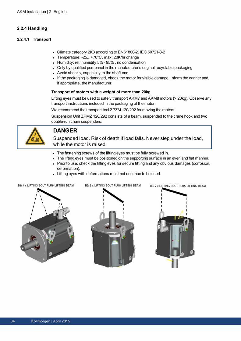
Transport of motors with a weight of more than 20kgLifting eyes must be used to safely transport AKM7 and AKM8motors (> 20kg). Observe anytransport instructions included in the packaging of themotor.We recommend the transport tool ZPZM 120/292 for moving themotors.Suspension Unit ZPMZ 120/292 consists of a beam, suspended to the crane hook and twodouble-run chain suspenders.
DANGERSuspended load. Risk of death if load falls. Never step under the load,while the motor is raised.
l The fastening screws of the lifting eyes must be fully screwed in.l The lifting eyes must be positioned on the supporting surface in an even and flat manner.l Prior to use, check the lifting eyes for secure fitting and any obvious damages (corrosion,deformation).
l Lifting eyes with deformations must not continue to be used.
34 Kollmorgen | April 2015
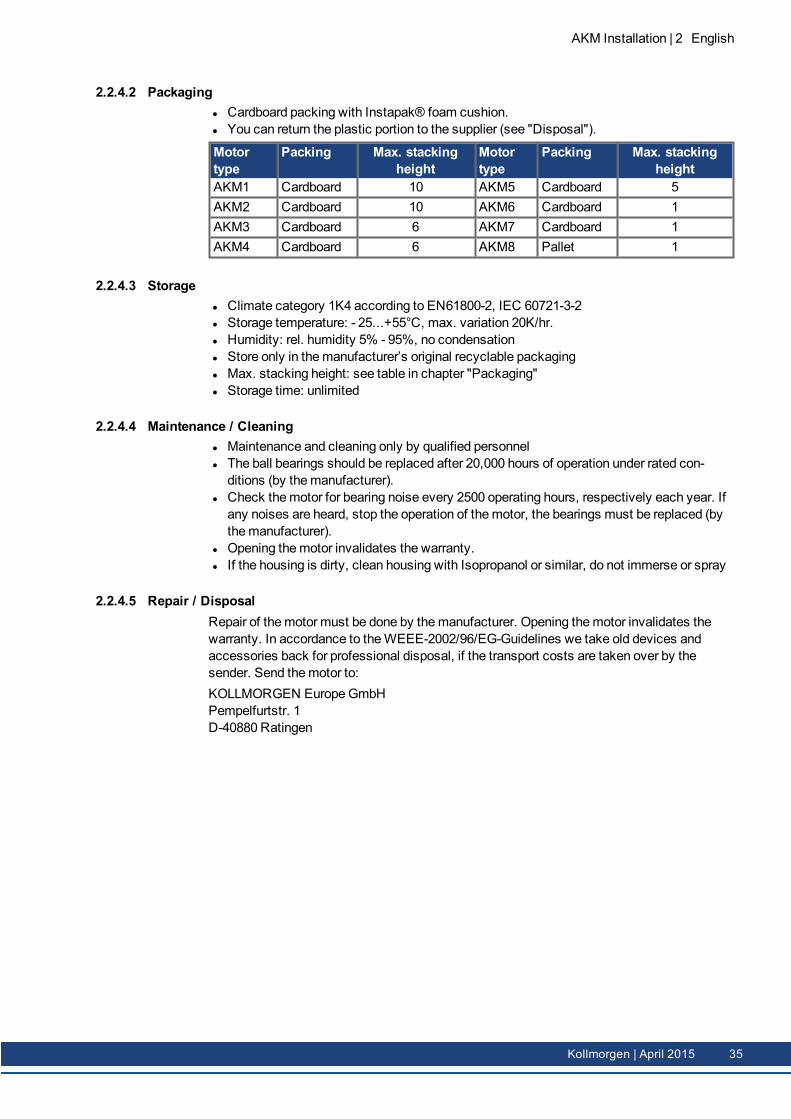
2.2.4.2 Packagingl Cardboard packing with Instapak® foam cushion.l You can return the plastic portion to the supplier (see "Disposal").
Motortype
Packing Max. stackingheight
Motortype
Packing Max. stackingheight
AKM1 Cardboard 10 AKM5 Cardboard 5AKM2 Cardboard 10 AKM6 Cardboard 1AKM3 Cardboard 6 AKM7 Cardboard 1AKM4 Cardboard 6 AKM8 Pallet 1
2.2.4.3 Storagel Climate category 1K4 according to EN61800-2, IEC 60721-3-2l Storage temperature: - 25...+55°C, max. variation 20K/hr.l Humidity: rel. humidity 5% - 95%, no condensationl Store only in themanufacturer’s original recyclable packagingl Max. stacking height: see table in chapter "Packaging"l Storage time: unlimited
2.2.4.4 Maintenance / Cleaningl Maintenance and cleaning only by qualified personnell The ball bearings should be replaced after 20,000 hours of operation under rated con-ditions (by themanufacturer).
l Check themotor for bearing noise every 2500 operating hours, respectively each year. Ifany noises are heard, stop the operation of themotor, the bearings must be replaced (bythemanufacturer).
l Opening themotor invalidates the warranty.l If the housing is dirty, clean housing with Isopropanol or similar, do not immerse or spray
2.2.4.5 Repair / DisposalRepair of themotor must be done by themanufacturer. Opening themotor invalidates thewarranty. In accordance to theWEEE-2002/96/EG-Guidelines we take old devices andaccessories back for professional disposal, if the transport costs are taken over by thesender. Send themotor to:KOLLMORGEN EuropeGmbHPempelfurtstr. 1D-40880 Ratingen
AKM Installation | 2 English
Kollmorgen | April 2015 35
AKM Installation | 2 English
2.3 Package
2.3.1 Delivery packagel Motor from the AKM seriesl Product manual (multi language) printed, one per delivery
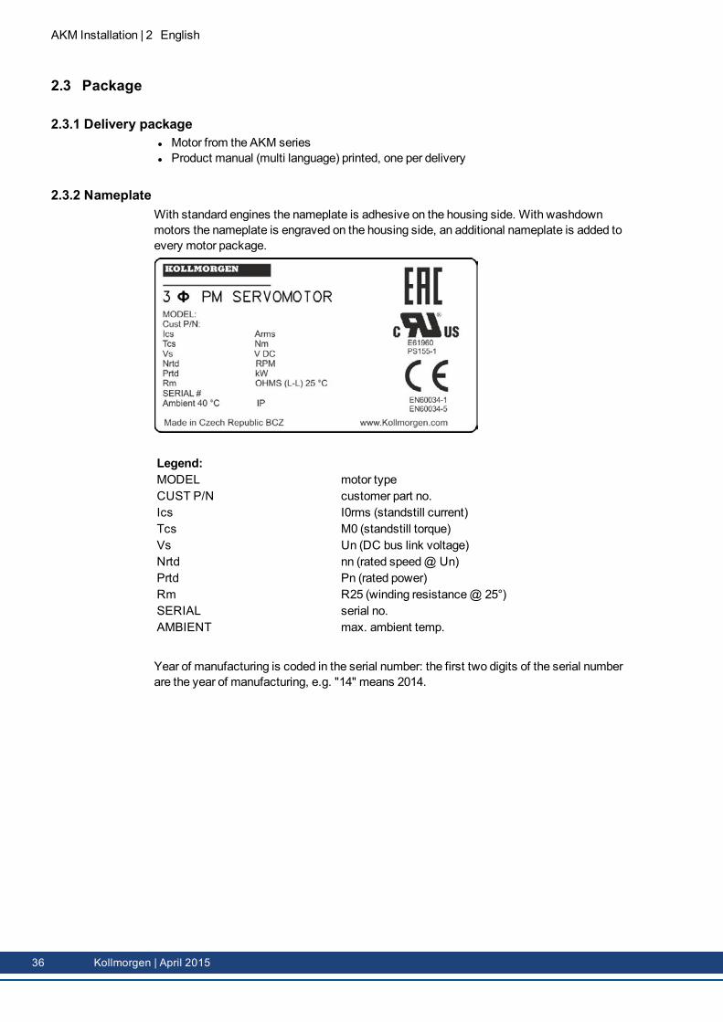
2.3.2 NameplateWith standard engines the nameplate is adhesive on the housing side. With washdownmotors the nameplate is engraved on the housing side, an additional nameplate is added toevery motor package.
Legend:MODEL motor typeCUST P/N customer part no.Ics I0rms (standstill current)Tcs M0 (standstill torque)Vs Un (DC bus link voltage)Nrtd nn (rated speed@ Un)Prtd Pn (rated power)Rm R25 (winding resistance@ 25°)SERIAL serial no.AMBIENT max. ambient temp.
Year of manufacturing is coded in the serial number: the first two digits of the serial numberare the year of manufacturing, e.g. "14" means 2014.
36 Kollmorgen | April 2015
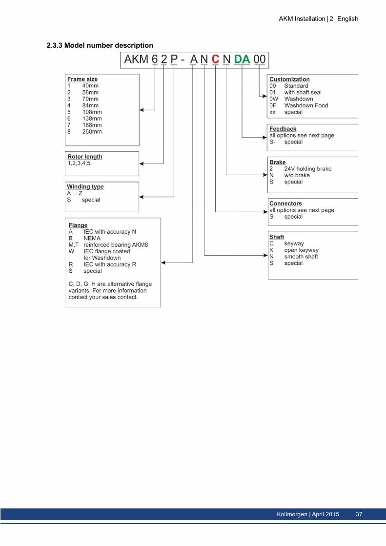
2.3.3 Model number description
AKM Installation | 2 English
Kollmorgen | April 2015 37
AKM Installation | 2 English
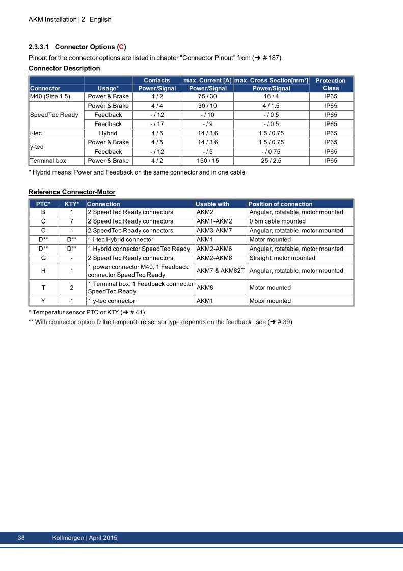
2.3.3.1 Connector Options (C)Pinout for the connector options are listed in chapter "Connector Pinout" from (➜ # 187).Connector Description
Contacts max. Current [A] max. Cross Section[mm²] ProtectionClassConnector Usage* Power/Signal Power/Signal Power/Signal
M40 (Size 1.5) Power & Brake 4 / 2 75 / 30 16 / 4 IP65
SpeedTec ReadyPower & Brake 4 / 4 30 / 10 4 / 1.5 IP65Feedback - / 12 - / 10 - / 0.5 IP65Feedback - / 17 - / 9 - / 0.5 IP65
i-tec Hybrid 4 / 5 14 / 3.6 1.5 / 0.75 IP65
y-tecPower & Brake 4 / 5 14 / 3.6 1.5 / 0.75 IP65Feedback - / 12 - / 5 - / 0.75 IP65
Terminal box Power & Brake 4 / 2 150 / 15 25 / 2.5 IP65
* Hybrid means: Power and Feedback on the same connector and in one cable
Reference Connector-MotorPTC* KTY* Connection Usable with Position of connectionB 1 2 SpeedTec Ready connectors AKM2 Angular, rotatable, motor mountedC 7 2 SpeedTec Ready connectors AKM1-AKM2 0.5m cable mountedC 1 2 SpeedTec Ready connectors AKM3-AKM7 Angular, rotatable, motor mountedD** D** 1 i-tec Hybrid connector AKM1 Motor mountedD** D** 1 Hybrid connector SpeedTec Ready AKM2-AKM6 Angular, rotatable, motor mountedG - 2 SpeedTec Ready connectors AKM2-AKM6 Straight, motor mounted
H 1 1 power connector M40, 1 Feedbackconnector SpeedTec Ready AKM7 & AKM82T Angular, rotatable, motor mounted
T 2 1 Terminal box, 1 Feedback connectorSpeedTec Ready AKM8 Motor mounted
Y 1 1 y-tec connector AKM1 Motor mounted
* Temperatur sensor PTC or KTY (➜ # 41)** With connector option D the temperature sensor type depends on the feedback , see (➜ # 39)
38 Kollmorgen | April 2015
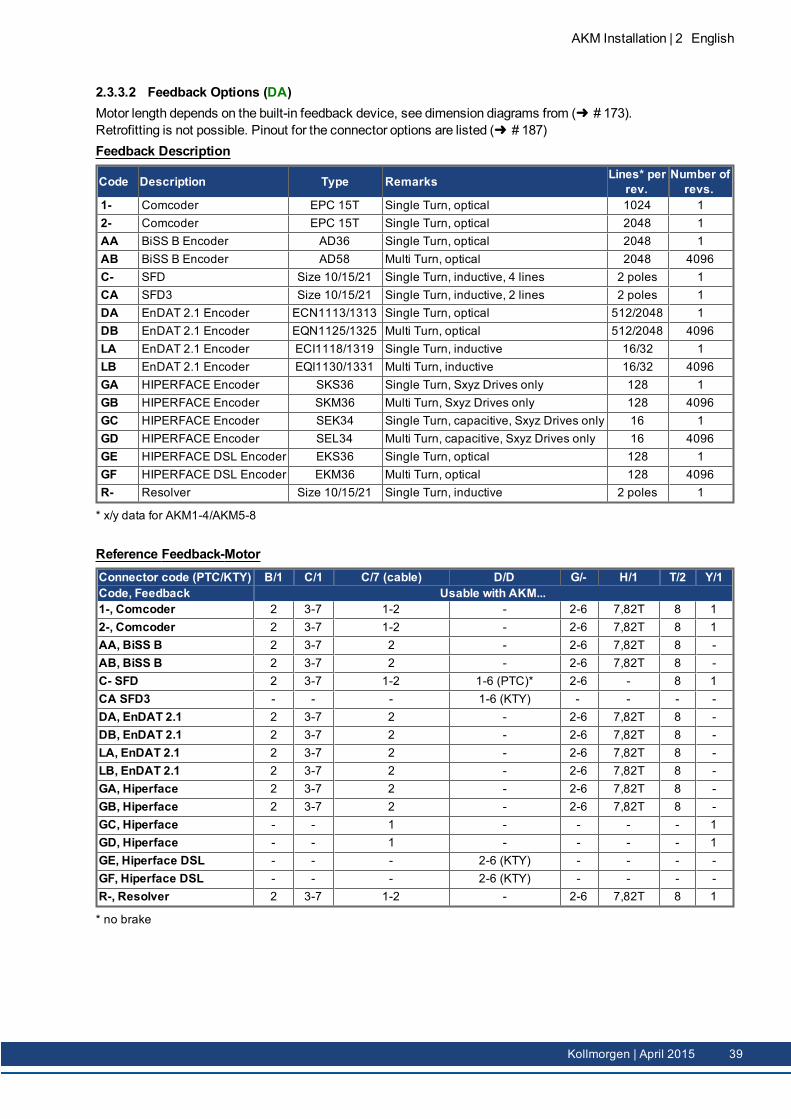
2.3.3.2 Feedback Options (DA)Motor length depends on the built-in feedback device, see dimension diagrams from (➜ # 173).Retrofitting is not possible. Pinout for the connector options are listed (➜ # 187)Feedback Description
Code Description Type Remarks Lines* perrev.
Number ofrevs.
1- Comcoder EPC 15T Single Turn, optical 1024 12- Comcoder EPC 15T Single Turn, optical 2048 1AA BiSS B Encoder AD36 Single Turn, optical 2048 1AB BiSS B Encoder AD58 Multi Turn, optical 2048 4096C- SFD Size 10/15/21 Single Turn, inductive, 4 lines 2 poles 1CA SFD3 Size 10/15/21 Single Turn, inductive, 2 lines 2 poles 1DA EnDAT 2.1 Encoder ECN1113/1313 Single Turn, optical 512/2048 1DB EnDAT 2.1 Encoder EQN1125/1325 Multi Turn, optical 512/2048 4096LA EnDAT 2.1 Encoder ECI1118/1319 Single Turn, inductive 16/32 1LB EnDAT 2.1 Encoder EQI1130/1331 Multi Turn, inductive 16/32 4096GA HIPERFACE Encoder SKS36 Single Turn, Sxyz Drives only 128 1GB HIPERFACE Encoder SKM36 Multi Turn, Sxyz Drives only 128 4096GC HIPERFACE Encoder SEK34 Single Turn, capacitive, Sxyz Drives only 16 1GD HIPERFACE Encoder SEL34 Multi Turn, capacitive, Sxyz Drives only 16 4096GE HIPERFACE DSL Encoder EKS36 Single Turn, optical 128 1GF HIPERFACE DSL Encoder EKM36 Multi Turn, optical 128 4096R- Resolver Size 10/15/21 Single Turn, inductive 2 poles 1
* x/y data for AKM1-4/AKM5-8
Reference Feedback-MotorConnector code (PTC/KTY) B/1 C/1 C/7 (cable) D/D G/- H/1 T/2 Y/1Code, Feedback Usable with AKM...1-, Comcoder 2 3-7 1-2 - 2-6 7,82T 8 12-, Comcoder 2 3-7 1-2 - 2-6 7,82T 8 1AA, BiSS B 2 3-7 2 - 2-6 7,82T 8 -AB, BiSS B 2 3-7 2 - 2-6 7,82T 8 -C- SFD 2 3-7 1-2 1-6 (PTC)* 2-6 - 8 1CA SFD3 - - - 1-6 (KTY) - - - -DA, EnDAT 2.1 2 3-7 2 - 2-6 7,82T 8 -DB, EnDAT 2.1 2 3-7 2 - 2-6 7,82T 8 -LA, EnDAT 2.1 2 3-7 2 - 2-6 7,82T 8 -LB, EnDAT 2.1 2 3-7 2 - 2-6 7,82T 8 -GA, Hiperface 2 3-7 2 - 2-6 7,82T 8 -GB, Hiperface 2 3-7 2 - 2-6 7,82T 8 -GC, Hiperface - - 1 - - - - 1GD, Hiperface - - 1 - - - - 1GE, Hiperface DSL - - - 2-6 (KTY) - - - -GF, Hiperface DSL - - - 2-6 (KTY) - - - -R-, Resolver 2 3-7 1-2 - 2-6 7,82T 8 1
* no brake
AKM Installation | 2 English
Kollmorgen | April 2015 39
AKM Installation | 2 English
2.4 Technical Description
2.4.1 General technical dataAmbient temperature(at rated values)
5...+40°C for site altitude up to 1000m amslIt is vital to consult our applications department for ambient tem-peratures above 40°C and encapsulatedmounting of themotors.
Permissible humidity(at rated values)
95% rel. humidity, no condensation
Power derating(currents and torques)
1%/K in range 40°C...50°C up to 1000m amslfor site altitude above 1000m amsl and 40°C6% up to 2000m amsl17% up to 3000m amsl30% up to 4000m amsl55% up to 5000m amslNo derating for site altitudes above 1000m amsl with tem-perature reduction of 10K / 1000m
Ball-bearing life ≥ 20.000 operating hoursTechnical data for every motor type can be found in chapter "Technical Data" from (➜ #159).
2.4.2 Standard features
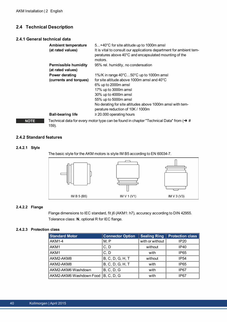
2.4.2.1 StyleThe basic style for the AKMmotors is style IM B5 according to EN 60034-7.
2.4.2.2 FlangeFlange dimensions to IEC standard, fit j6 (AKM1: h7), accuracy according to DIN 42955.Tolerance class: N, optional R for IEC flange.
2.4.2.3 Protection classStandard Motor Connector Option Sealing Ring Protection classAKM1-4 M, P with or without IP20AKM1 C, D without IP40AKM1 C, D with IP65AKM2-AKM8 B, C, D, G, H, T without IP54AKM2-AKM8 B, C, D, G, H, T with IP65AKM2-AKM6Washdown B, C, D, G with IP67AKM2-AKM6Washdown Food B, C, D, G with IP67
40 Kollmorgen | April 2015
2.4.2.4 Insulation material classThemotors come up to insulationmaterial class F according to IEC 60085 (UL1446 class F).
2.4.2.5 SurfaceThemotors are coated with polyester powder coating in matt black. This finish is not res-istant against solvents (e.g. trichlorethylene, nitro-thinners, or similar).
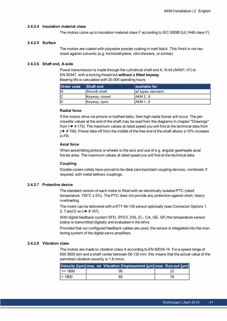
2.4.2.6 Shaft end, A-sidePower transmission is made through the cylindrical shaft end A, fit k6 (AKM1: h7) toEN 50347, with a locking thread but without a fitted keyway.Bearing life is calculated with 20.000 operating hours.
Order code Shaft end available forN Smooth shaft all types, standardC Keyway, closed AKM 2...8K Keyway, open AKM 1...8
Radial forceIf themotors drive via pinions or toothed belts, then high radial forces will occur. The per-missible values at the end of the shaft may be read from the diagrams in chapter "Drawings"from (➜ # 173). Themaximum values at rated speed you will find at the technical data from(➜ # 159). Power take-off from themiddle of the free end of the shaft allows a 10% increasein FR.
Axial forceWhen assembling pinions or wheels to the axis and use of e.g. angular gearheads axialforces arise. Themaximum values at rated speed you will find at the technical data.
CouplingDouble-coned collets have proved to be ideal zero-backlash coupling devices, combined, ifrequired, with metal bellows couplings.
2.4.2.7 Protective deviceThe standard version of eachmotor is fitted with an electrically isolated PTC (ratedtemperature 155°C ± 5%). The PTC does not provide any protection against short, heavyoverloading.Themotor can be delivered with a KTY 84-130 sensor optionally (see Connector Options 1,2, 7 and D on (➜ # 187).With digital feedback system SFD, SFD3, DSL (C-, CA, GE, GF) the temperature sensorstatus is transmitted digitally and evaluated in the drive.Provided that our configured feedback cables are used, the sensor is integrated into themon-itoring system of the digital servo amplifiers.
2.4.2.8 Vibration classThemotors aremade to vibration class A according to EN 60034-14. For a speed range of600-3600 rpm and a shaft center between 56-132 mm, this means that the actual value of thepermitted vibration severity is 1.6 mm/s.
Velocity [rpm] max. rel. Vibration Displacement [µm] max. Run-out [µm]<= 1800 90 23> 1800 65 16
AKM Installation | 2 English
Kollmorgen | April 2015 41
AKM Installation | 2 English
2.4.3 Shaft sealIf AKMis connected to amachine flange with unsealed shaft region, then the shaft seal(option "01") ensures the shaft sealing. Run-in procedure of shaft seal needs to be performedto ensure rated performance of AKMmotors.Execute the following run-in procedure:l 30minutes no load run at maximum speed in CW direction,l 30minutes self-cooling of motor,l 30minutes no load run at maximum speed in CCW direction,l 30minutes self-cooling of motor.This cycle should be repeated 3 times.
2.4.4 Wiring technology
2.4.4.1 ConnectorsDescriptions of the available connectors: (➜ # 37). Connector pinout: from (➜ # 187).
2.4.4.2 Wire cross sections
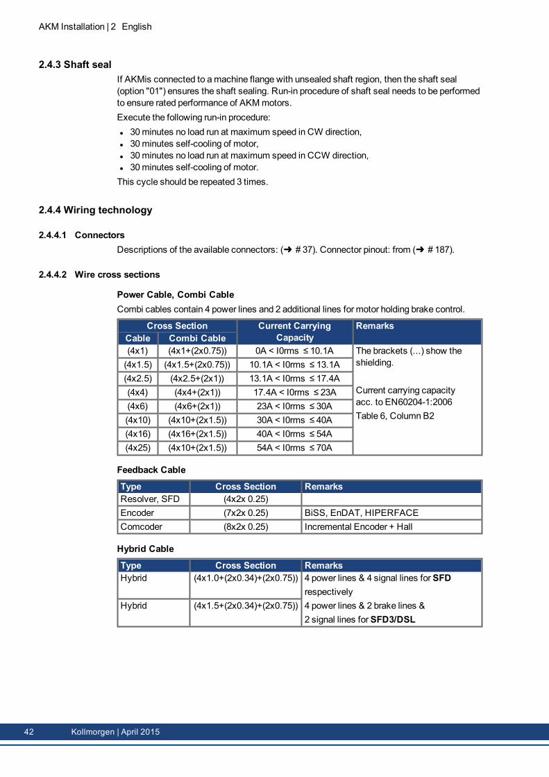
Power Cable, Combi CableCombi cables contain 4 power lines and 2 additional lines for motor holding brake control.
Cross Section Current CarryingCapacity
RemarksCable Combi Cable(4x1) (4x1+(2x0.75)) 0A < I0rms ≤ 10.1A The brackets (...) show the
shielding.
Current carrying capacityacc. to EN60204-1:2006Table 6, Column B2
(4x1.5) (4x1.5+(2x0.75)) 10.1A < I0rms ≤ 13.1A(4x2.5) (4x2.5+(2x1)) 13.1A < I0rms ≤ 17.4A(4x4) (4x4+(2x1)) 17.4A < I0rms ≤ 23A(4x6) (4x6+(2x1)) 23A < I0rms ≤ 30A(4x10) (4x10+(2x1.5)) 30A < I0rms ≤ 40A(4x16) (4x16+(2x1.5)) 40A < I0rms ≤ 54A(4x25) (4x10+(2x1.5)) 54A < I0rms ≤ 70A
Feedback Cable
Type Cross Section RemarksResolver, SFD (4x2x 0.25)Encoder (7x2x 0.25) BiSS, EnDAT, HIPERFACEComcoder (8x2x 0.25) Incremental Encoder + Hall
Hybrid Cable
Type Cross Section RemarksHybrid (4x1.0+(2x0.34)+(2x0.75)) 4 power lines & 4 signal lines forSFD
respectively4 power lines & 2 brake lines &2 signal lines forSFD3/DSL
Hybrid (4x1.5+(2x0.34)+(2x0.75))
42 Kollmorgen | April 2015
2.4.5 Holding brakeAll motors are optionally available with a holding brake. A spring applied brake (24V DC) isintegrated into themotors. When this brake is de-energized it blocks the rotor.
WARNINGIf there is a suspended load (vertical axes), the motor's holding brake isreleased, and, at the same time, the servo drive does not produce any out-put, the load may fall down! Risk of injury for the personnel operating themachine. Functional safety in case of hanging loads (vertical axes) canbe ensured only by using an additional, external, mechanical brake.
The holding brakes are designed as standstill brakes and are not suited for repeated oper-ational braking. In the case of frequent, operational braking, premature wear and failure of theholding brake is to be expected.Themotor length increases when a holding brake is mounted.The holding brake can be controlled directly by the servo amplifier (no personal safety !), thewinding is suppressed in the servo amplifier— additional circuitry is not required (see instruc-tions manual of the servo amplifier). If the holding brake is not controlled directly by the servoamplifier, an additional wiring (e.g. varistor) is required. Consult our support department.
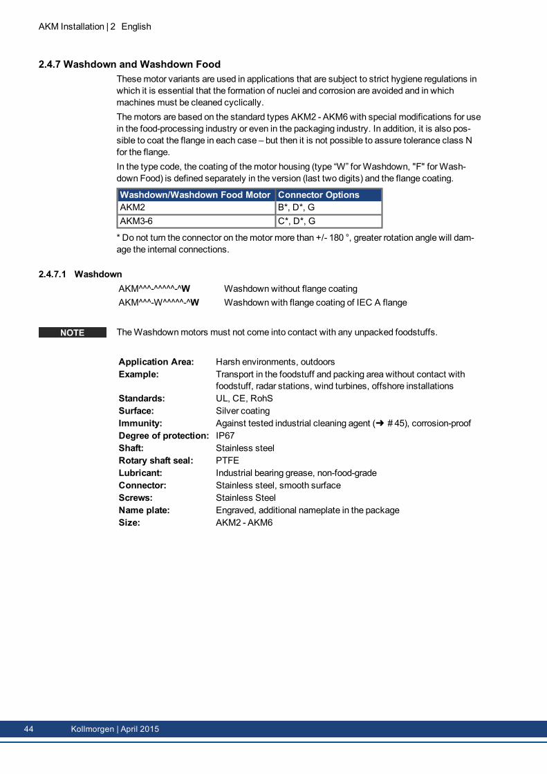
2.4.6 Fan for AKM7For the AKM7model size, an add-on kit for forced ventilation is available. The integrated fanenables up to 30% more power output for the AKM7motors. Assembly instructions for thefan kit is contained within the scope of delivery of the add-on kit.
The fan housing can bemounted either with both the suppliedbrackets and spacers or with the brackets only. The choice ofmountingmethod depends on the application. If strong vibra-tions are expected, you should use both brackets andspacers. Motors with integrated brakes require the longsspacers.
Make sure, that free air flow is available for the fan. Keep a space of at least 25mm behindthe fan guard.Themotors become dirty considerably faster due to forced convection. Dirt deposits lead tofalling cooling capacity and can put themotors at risk. Dust may burn in case of over-heating.So clean the air duct, the fan, and themotor at regular intervals.By adding a fan, themounting dimensions of AKM7motors increase.In case of AKM7motors with connector option "C", winding "Q" and forced ventilation youmust limit themotor current to 24 A for connector protection.You can find technical information on AKM7motors with fans (➜ # 171).You can find the dimensional drawing for AKM7motors with fans on (➜ # 182).
AKM Installation | 2 English
Kollmorgen | April 2015 43
AKM Installation | 2 English
2.4.7 Washdown and Washdown FoodThesemotor variants are used in applications that are subject to strict hygiene regulations inwhich it is essential that the formation of nuclei and corrosion are avoided and in whichmachines must be cleaned cyclically.Themotors are based on the standard types AKM2 - AKM6with special modifications for usein the food-processing industry or even in the packaging industry. In addition, it is also pos-sible to coat the flange in each case – but then it is not possible to assure tolerance class Nfor the flange.In the type code, the coating of themotor housing (type “W” forWashdown, "F" forWash-down Food) is defined separately in the version (last two digits) and the flange coating.
Washdown/Washdown Food Motor Connector OptionsAKM2 B*, D*, GAKM3-6 C*, D*, G
* Do not turn the connector on themotor more than +/- 180 °, greater rotation angle will dam-age the internal connections.
2.4.7.1 WashdownAKM^^^-^^^^^-^WAKM^^^-W^^^^^-^W
Washdownwithout flange coatingWashdownwith flange coating of IEC A flange
TheWashdownmotors must not come into contact with any unpacked foodstuffs.
Application Area: Harsh environments, outdoorsExample: Transport in the foodstuff and packing area without contact with
foodstuff, radar stations, wind turbines, offshore installationsStandards: UL, CE, RohSSurface: Silver coatingImmunity: Against tested industrial cleaning agent (➜ # 45), corrosion-proofDegree of protection: IP67Shaft: Stainless steelRotary shaft seal: PTFELubricant: Industrial bearing grease, non-food-gradeConnector: Stainless steel, smooth surfaceScrews: Stainless SteelName plate: Engraved, additional nameplate in the packageSize: AKM2 - AKM6
44 Kollmorgen | April 2015
2.4.7.2 Washdown FoodAKM^^^-^^^^^-^FAKM^^^-W^^^^^-^F
Washdown Food without flange coatingWashdown Food with flange coating of IEC A flange
The surface of theWashdown foodmotor has passed all tests as per FDA GlobalMigrationfor indirect contact with foodstuffs. Any direct contact with unpacked foodstuffs is not per-mitted.
Application Area: Foodstuffs and drinks industry, no direct contact with unpackedfoodstuff
Example: Cutting, packing and filling without direct contact with foodstuffs.Motor laterally or below the food.
Standards: UL, CE, RoHs, FDASurface: White coatingImmunity: Against tested industrial cleaning agent (➜ # 45), corrosion-proofGlobal Migration: US FDA Regulations 21 CFR 175.300, Condition of Use EDegree of protection: IP67Shaft: Stainless steelRotary shaft seal: PTFE as per FDALubricant: food-grade as per FDAConnector: Stainless steel, smooth surfaceScrews: Stainless SteelName plate: Engraved, additional nameplate in the packageSize: AKM2 - AKM6
2.4.7.3 Tested and confirmed properties with respect to cleaning agentsThe testing lab of ECOLAB DeutschlandGmbH tested the resistance of theWashdown andWashdown Food surfaces to the following industrial cleaning agents:l P3-topactive DESl P3-topactive LAl P3-topax 56l P3-topax 66l P3-topax 91In the process, the surfaces were immersed in the respective cleaning agent at room tem-perature for 28 days. This corresponds to approx. 2,500 cleaning cycles with 15-minute con-tact each with the cleaning agent or 1,500 cleaning cycles with cleaning and subsequentdisinfection.The certificates are located in our Product WIKI on the Approvals page.
Kollmorgen can only give a guarantee for themotor's lifecycle if the tested cleansing agentsare used. Any cleansing agent other than thosementioned above can be tested by Koll-morgen upon request and, if appropriate, be approved.
AKM Installation | 2 English
Kollmorgen | April 2015 45
AKM Installation | 2 English
2.4.7.4 Installation and operating conditionsl Themotors may be used only in ambient temepratures up to 50 °C.l If the front flange is coated, the tolerance class N is not guaranteed.Motors with flanges without wash-outdown coating: The flange surfacemust be protected bysuitable assembly against the influence by cleaning agents.
2.4.7.5 Cleaning planRecommended cleaning plan (short form) with tested cleaning agents:
Flushing with water (40 °... 50 °C)Flushing with low pressure. From top to bottom in the direction of the drain. Clean the drain.
Foam cleaningFoaming from top to bottom.Alkaline: P3-topactive LA or P3-topax 66 (2-5%, 15min daily)Acid: P3-topax 56 (2%, if necessary 15min)Temperature: cold up to 40 °C
DisinfectionSpraying with wayer (40 °... 50 °C) with low pressure. From top to bottom.Spray disinfection: P3-topax 91 (1-2%, if necessary 30-60min)Foam disinfection: P3-topactiv DES (1-3%, if necessary 10-30min)
46 Kollmorgen | April 2015
2.5 Mechanical InstallationDimension drawings can be found in chapter "Dimension Drawings"(➜ # 173).
2.5.1 Important NotesOnly qualified staff with knowledge of mechanical engineering are permitted to assemble themotor.l Protect themotor from unacceptable stresses. During transport and handling no com-ponents must be damaged.
l The site must be free of conductive and aggressivematerial. For V3-mounting (shaft endupwards), make sure that no liquids can enter the bearings. If an encapsulated assemblyis required, please consult Kollmorgen beforehand.
l Ensure an unhindered ventilation of themotors and observe the permissible ambient andflange temperatures. For ambient temperatures above 40°C please consult our applic-ations department beforehand. Ensure that there is adequate heat transfer in the sur-roundings and themotor flange.
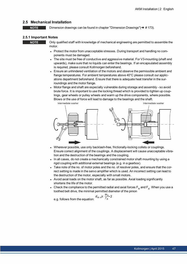
l Motor flange and shaft are especially vulnerable during storage and assembly - so avoidbrute force. It is important to use the locking thread which is provided to tighten up coup-lings, gear wheels or pulley wheels and warm up the drive components, where possible.Blows or the use of force will lead to damage to the bearings and the shaft.
l Wherever possible, use only backlash-free, frictionally-locking collets or couplings.Ensure correct alignment of the couplings. A displacement will cause unacceptable vibra-tion and the destruction of the bearings and the coupling.
l In all cases, do not create amechanically constrainedmotor shaft mounting by using arigid coupling with additional external bearings (e.g. in a gearbox).
l Take note of the no. of motor poles and the no. of resolver poles, and ensure that the cor-rect setting is made in the servo amplifier which is used. An incorrect setting can lead tothe destruction of themotor, especially with small motors.
l Avoid axial loads on themotor shaft, as far as possible. Axial loading significantlyshortens the life of themotor.
l Check the compliance to the permitted radial and axial forces FR and FA. When you use atoothed belt drive, theminimal permitted diameter of the pinion
e.g. follows from the equation:� � � �� �� � �
AKM Installation | 2 English
Kollmorgen | April 2015 47
AKM Installation | 2 English
2.6 Electrical InstallationPinout for the connector can be found in chapter "Connector Pinout" from (➜ # 173). Pinoutof the servo amplifier's end can be found in the instructions manual of the servo amplifier.
2.6.1 Important notesOnly staff qualified and trained in electrical engineering are allowed to wire up themotor.
DANGERAlways make sure that the motors are de-energized during assembly andwiring, i.e. no voltage may be switched on for any piece of equipmentwhich is to be connected.There is a risk of death or severe injury from touching exposed contacts.Ensure that the switch cabinet remains turned off (barrier, warning signsetc.). The individual voltages will only be turned on again during setup.Never undo the electrical connections to the motor while it is energized.Risk of electric shock! In unfavorable circumstances, electric arcs canarise causing harm to people and damaging contacts.A dangerous voltage, resulting from residual charge, can be still presenton the capacitors up to 10 minutes after switch-off of the mains supply.Even when the motor is not rotating, control and power leads may be live.Measure the DC-link voltage and wait until it has fallen below 60V.
The ground symbol , which you will find in the wiring diagrams, indicates that youmust provide an electrical connection, with as large a surface area as possible, between theunit indicated and themounting plate in the switch cabinet. This connection is to suppressHF interference andmust not be confused with the PE (protective earth) symbol (pro-tectivemeasure to EN 60204).
To wire up themotor, use the wiring diagrams in the Installation and Setup Instructions of theservo amplifier which is used.
48 Kollmorgen | April 2015
2.6.2 Guide for electrical installationl Check that the servo amplifier andmotor match each other. Compare the rated voltageand rated current of the unit. Carry out the wiring according to the wiring diagram in theinstructions manual of the servo amplifier. The connections to themotor are shown inchapter "Connector Pinout" from (➜ # 173).
l Install all cables carrying a heavy current with an adequate cross-section, as perEN 60204. The recommended cross-section can be found in the Technical data.
In case of longmotor cables (>25m) and dependent on the type of the used servo amplifier amotor choke (3YL or 3YLN)must be switched into themotor cable (see instructions manualof the servo amplifier and accessory manual).
l Ensure that there is proper earthing of the servo amplifier and themotor. Use correct earth-ing and EMC-shielding according to the instructions manual of the servo amplifier whichis used. Earth themounting plate andmotor casing.
l If a motor power cable is used which includes integral brake control leads, then thesebrake control leads must be shielded. The shieldingmust be connected at both ends (seeinstructions manual of the servo amplifier).
l Cabling:o Route power cables as separately as possible from control cableso Connect up the resolver or encoder.o Connect themotor cables, install motor chokes close to the amplifiero Connect shields to shielding terminals or EMC connectors at both endso Connect the holding brake, if usedo Connect shielding at both ends.
l Connect up all shielding via a wide surface-area contact (low impedance) andmetallizedconnector housings or EMC-cable glands.
l Requirements to cablematerial:CapacityMotor cable: less than 150 pF/mResolver cable: less than 120 pF/m
2.6.3 Connection of the motors with preassembled cablesl Carry out the wiring in accordance with the valid standards and regulations.l Only use Kollmorgen preassembled shielded cables for the resolver and power con-nections.
l Incorrectly installed shielding leads to EMC interference and has an adverse effect onsystem function.
l Themaximum cable length is defined in the instructions manual of the used servo amp-lifier.
For a detailed description of configured cables, please refer to the regional accessoriesmanual.
AKM Installation | 2 English
Kollmorgen | April 2015 49
AKM Installation | 2 English
2.7 Setup
2.7.1 Important notes
Only specialist personnel with extensive knowledge in the areas of electrical engineering /drive technology are allowed to commission the drive unit of servo amplifier andmotor.
DANGERDeadly voltages can occur, up to 900 V. Risk of electric shock! Check thatall live connection points are safe against accidental contact.Never undo the electrical connections to the motor when it is live. Risk ofelectric shock! The residual charge in the capacitors of the drive can pro-duce dangerous voltages up to 10 minutes after the mains supply hasbeen switched off.Even when the motor is not rotating, control and power leads may be live.Measure the DC-link voltage and wait until it has fallen below 60 V.
CAUTIONThe surface temperature of the motor can exceed 100°C in operation. Danger of light burns! Check (measure) the temperature of the motor. Wait until the motor has cooled down below 40°C before touching it.
CAUTIONThe drive performing unplanned movements during commissioning can-not be ruled out.Make sure that, even if the drive starts to move unintentionally, no dangercan result for personnel or machinery.The measures you must take in this regard for your task are based on therisk assessment of the application.
50 Kollmorgen | April 2015

2.7.2 Guide for setupThe procedure for setup is described as an example. A different methodmay be appropriateor necessary, depending on the application of the equipment.1. Check the assembly and orientation of themotor.2. Check the drive components (clutch, gear unit, belt pulley) for the correct seating and set-
ting (observe the permissible radial and axial forces).3. Check the wiring and connections to themotor and the servo amplifier. Check that the
earthing is correct.4. Test the function of the holding brake, if used. (apply 24 V, brakemust be released).5. Check whether the rotor of themotor revolves freely (release the brake, if necessary).
Listen out for grinding noises.6. Check that all the requiredmeasures against accidental contact with live andmoving
parts have been carried out.7. Carry out any further tests which are specifically required for your system.8. Now commission the drive according to the setup instructions for the servo amplifier.9. In multi-axis systems, individually commission each drive unit (amplifier andmotor).
AKM Installation | 2 English
Kollmorgen | April 2015 51
AKM Installation | 2 English
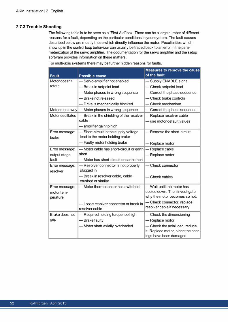
2.7.3 Trouble ShootingThe following table is to be seen as a “First Aid” box. There can be a large number of differentreasons for a fault, depending on the particular conditions in your system. The fault causesdescribed below aremostly those which directly influence themotor. Peculiarities whichshow up in the control loop behaviour can usually be traced back to an error in the para-meterization of the servo amplifier. The documentation for the servo amplifier and the setupsoftware provides information on thesematters.For multi-axis systems theremay be further hidden reasons for faults.
Fault Possible causeMeasures to remove the causeof the fault
Motor doesn’trotate
—Servo-amplifier not enabled—Break in setpoint lead—Motor phases in wrong sequence—Brake not released—Drive is mechanically blocked
—Supply ENABLE signal—Check setpoint lead—Correct the phase sequence—Check brake controls—Check mechanism
Motor runs away —Motor phases in wrong sequence —Correct the phase sequenceMotor oscillates —Break in the shielding of the resolver
cable— amplifier gain to high
—Replace resolver cable— usemotor default values
Error message:brake
—Short-circuit in the supply voltagelead to themotor holding brake—Faulty motor holding brake
—Remove the short-circuit
—ReplacemotorError message:output stagefault
—Motor cable has short-circuit or earthshort—Motor has short-circuit or earth short
—Replace cable—Replacemotor
Error message:resolver
—Resolver connector is not properlyplugged in—Break in resolver cable, cablecrushed or similar
—Check connector
—Check cables
Error message:motor tem-perature
—Motor thermosensor has switched
— Loose resolver connector or break inresolver cable
—Wait until themotor hascooled down. Then investigatewhy themotor becomes so hot.—Check connector, replaceresolver cable if necessary
Brake does notgrip
—Required holding torque too high—Brake faulty—Motor shaft axially overloaded
—Check the dimensioning—Replacemotor—Check the axial load, reduceit. Replacemotor, since the bear-ings have been damaged
52 Kollmorgen | April 2015
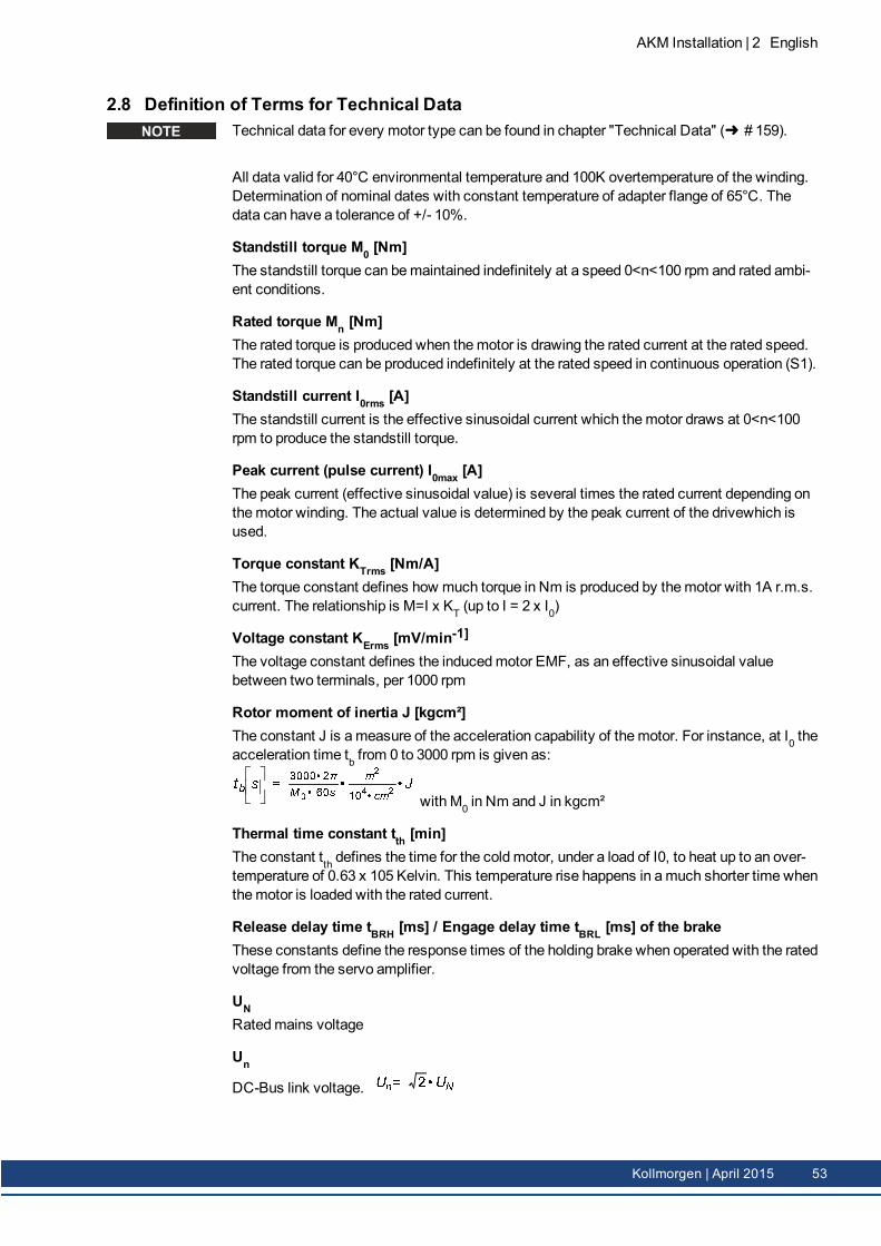
2.8 Definition of Terms for Technical DataTechnical data for every motor type can be found in chapter "Technical Data" (➜ # 159).
All data valid for 40°C environmental temperature and 100K overtemperature of the winding.Determination of nominal dates with constant temperature of adapter flange of 65°C. Thedata can have a tolerance of +/- 10%.
Standstill torque M0 [Nm]The standstill torque can bemaintained indefinitely at a speed 0<n<100 rpm and rated ambi-ent conditions.
Rated torque Mn [Nm]The rated torque is produced when themotor is drawing the rated current at the rated speed.The rated torque can be produced indefinitely at the rated speed in continuous operation (S1).
Standstill current I0rms [A]The standstill current is the effective sinusoidal current which themotor draws at 0<n<100rpm to produce the standstill torque.
Peak current (pulse current) I0max [A]The peak current (effective sinusoidal value) is several times the rated current depending onthemotor winding. The actual value is determined by the peak current of the drivewhich isused.
Torque constant KTrms [Nm/A]The torque constant defines how much torque in Nm is produced by themotor with 1A r.m.s.current. The relationship is M=I x KT (up to I = 2 x I0)
Voltage constant KErms [mV/min-1]
The voltage constant defines the inducedmotor EMF, as an effective sinusoidal valuebetween two terminals, per 1000 rpm
Rotor moment of inertia J [kgcm²]The constant J is ameasure of the acceleration capability of themotor. For instance, at I0 theacceleration time tb from 0 to 3000 rpm is given as:� � �� � �� �� � � � � � � � � � � � �� �
with M0 in Nm and J in kgcm²
Thermal time constant tth [min]The constant tth defines the time for the cold motor, under a load of I0, to heat up to an over-temperature of 0.63 x 10⁵ Kelvin. This temperature rise happens in amuch shorter time whenthemotor is loaded with the rated current.
Release delay time tBRH [ms] / Engage delay time tBRL [ms] of the brakeThese constants define the response times of the holding brake when operated with the ratedvoltage from the servo amplifier.
UNRatedmains voltage
Un
DC-Bus link voltage. � �� � �� �
AKM Installation | 2 English
Kollmorgen | April 2015 53

AKM Installation | 2 English
54 Kollmorgen | April 2015