Embed Size (px)
Citation preview

INTEGRATED ELECTRONIC DIAGNOSTIC TOOL
AXONE 2000
USERS’ MANUAL
release 2.0

2
OVERVIEW: 1
3
KEYBOARD:
1. Display contrast adjustment key (to use together with the vertical arrows keys)2. Vertical arrows keys (vertical cursor movements)3. ENTER key (options’ confirmation)4. BACK key (returns to the previous option)5. Horizontal arrows keys (horizontal cursor movements)6. HELP key (on-line guide, when foreseen)7. DELETE DATA key8. AUX 2 key (auxiliary functions)9. AUX 1 key (auxiliary functions)10. Increase / decrease keys11. ON / OFF switch12. Numeric keyboard
4
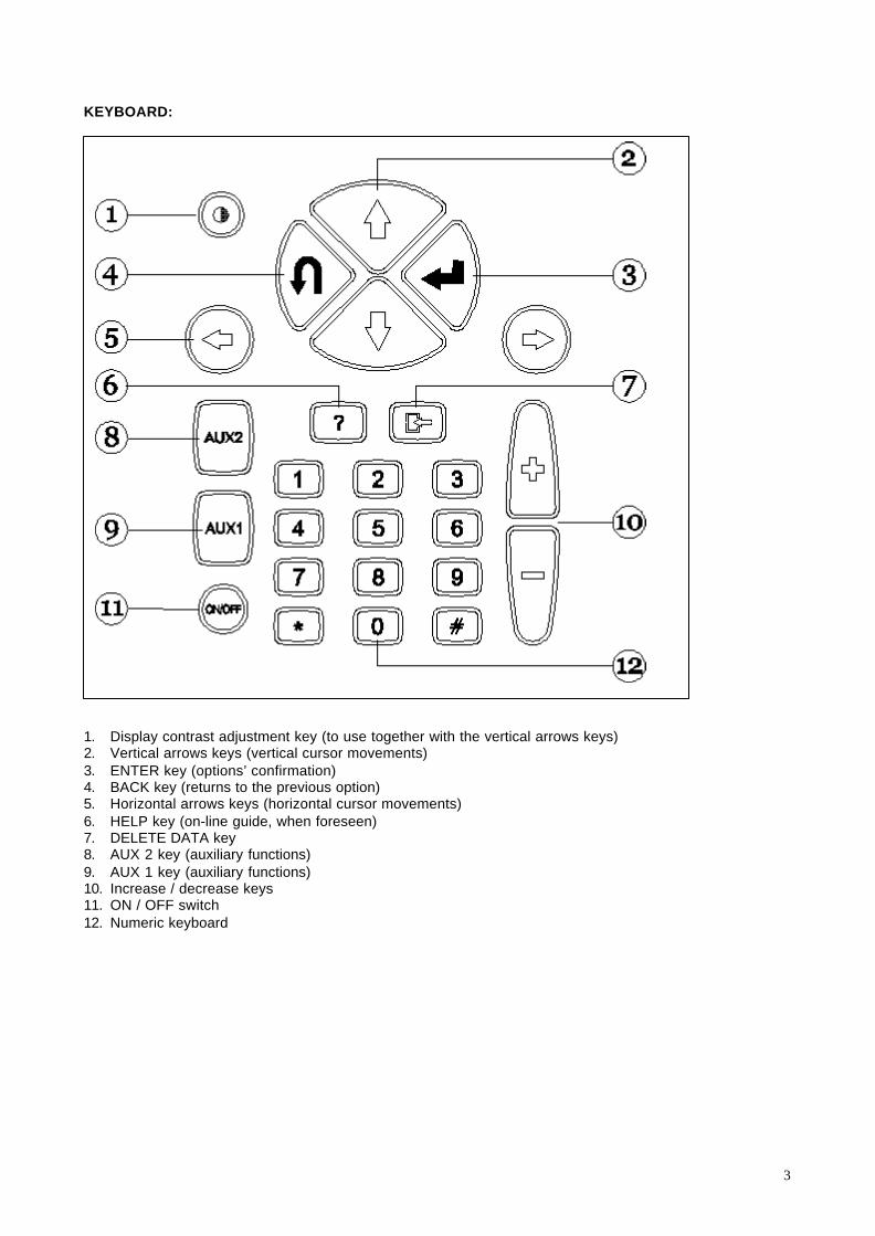
INTERFACE MODULES
SUPPLIED MODULES :
OBD (On Board Diagnosis) – self-diagnosis moduleACQ (acquisition) – measurements / tester moduleMODEM - updating system via Internet (NOT YET AVAILABLE)
Modules’ insertion (to be operated with AXONE2000 switched OFF)

5
MEMORY CARD
36 MB FLASH-ROM card with AXONE2000 software inside(to be inserted with AXONE2000 switched OFF)
ELECTRICAL FEEDING
Feeding voltage: 12-15 V D.C.Power consumption : 10 WInternal Ni-MH battery (power range: 2 hours)
Battery cover detachment: inserta screwdriver where indicatedand unlock the retaining clip.The battery cover will open.

6
BATTERY RECHARGING:
Connect the battery charger to a 220 V output.Don’t use the battery charger for a direct electrical feeding of AXONE 2000. Recharging battery useonly.
ELECTRICAL FEEDING BY VEHICLE’S BATTERYNOTE: THIS KIND OF CONNECTION IS NECESSARY FOR THE OBD MODULE UTILIZATION: ECU UNITDIALOGUE IS POSSIBLE ONLY IF AXONE IS CONNECTED TO THE GROUND REFERENCE OF THEECU UNIT (THE BATTERY’S MINUS END)
1. Connecting cable2. Connector3. Feeding socket4. Battery clamps cable
BATTERY RECHARGING ADVICES:
1. First two recharges must be done for atleast 12 hours
2. when charging cycle is complete, the batterycharger will authomatically switch off
3. start charging process when AXONE2000 hasreached room’s temperature (20°C)
NOTE: feeding AXONE2000 withthe vehicle’s battery, the internalbattery, if necessary, isauthomatically recharged.
7
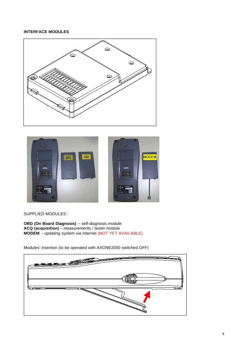
AXONE 2000 activation procedure:
1. Insert the battery pack as explained in the attached instructions chart;2. If, switching the instrument on, the battery level is low, charge the battery for at least 12
hours;3. The software will open an activation screenshot;4. The activation screenshot opens a code-insertion window;5. Call telephone number +39 0422.8410136. Ask for “Aprilia AXONE activation”7. Mrs. Francesca Teston will answer you;8. Tell AXONE serial number (located on the back of the instrument) and eventually other
reference data;9. Insert through the keyboard the code supplied by Mrs. Francesca Teston;10. Use “up arrow” and “down arrow” keys to select code’s numbers and letters;11. Confirm with the “ENTER” key every number / letter;12. At the end of the sequence, AXONE is permanently activated.
2

8
OBD MODULE (FIRMWARE) UPDATING PROCEDURE
To activate some specific functions, after activating AXONE inserting the code number it is necessary toinsert the OBD module with the instrument switched off and follow this updating procedure.
Select the “ Aggiornamento firmware”(“firmware updating”) option with thehorizontal arrows. Press “ENTER”
Switch AXONE on and select the“SERVIZIO” (“SERVICE”) icon with thehorizontal arrows. Press “ENTER”

9
Confirm pressing “ENTER” the “SI”(“YES”) option, to confirm the will toupdate the firmware.
The procedure can last 4 minutes:press “ENTER” and wait.

10
Don’t touch the keyboard until theupdating is in progress.
Thumb up: OBD module updatingis completed.Press “ENTER” to exit.
11
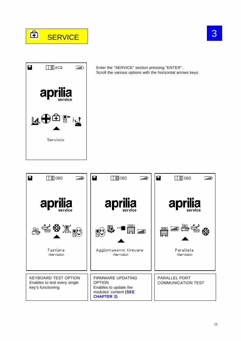
SERVICE
KEYBOARD TEST OPTIONEnables to test every singlekey’s functioning
FIRMWARE UPDATINGOPTIONEnables to update themodules’ content (SEECHAPTER 2)
PARALLEL PORTCOMMUNICATION TEST
Enter the “SERVICE” section pressing “ENTER” .Scroll the various options with the horizontal arrows keys.
3

12
SERIAL PORTCOMMUNICATION TEST
MAIN SCREENSHOTCUSTOMIZING OPTIONEnables to write the Dealer’sname on the main screenshot
RAPID INTERNAL BATTERYDISCHARGE PROCESS withgraphic discharge curveavailable
AXONE2000 DISABLING(FACTORY USE ONLY)
DO NOT USE THIS OPTION
AXONE2000 RE-ENABLING(FACTORY USE ONLY)
DO NOT USE THIS OPTION
BIOS UPDATING (FACTORYUSE ONLY)
DO NOT USE THIS OPTION

13
UPDATINGS
Enter the “UPDATINGS” section pressing “ENTER” .Scroll the various options with the horizontal arrows keys.
PC connection via serialcable: allows the memory cardupdating via personalcomputer.
4
MODEM MODULE REQUIREDTHIS MEMORY CARD UPDATING SYSTEM REQUIRES THESPECIFIC MODEM MODULE, TO BE CONNECTED TO A PHONELINE THROUGH A DEDICATED CABLE.SWITCH AXONE2000 OFF AND INSERT THE MODEM MODULE(NOT YET AVAILABLE).
14
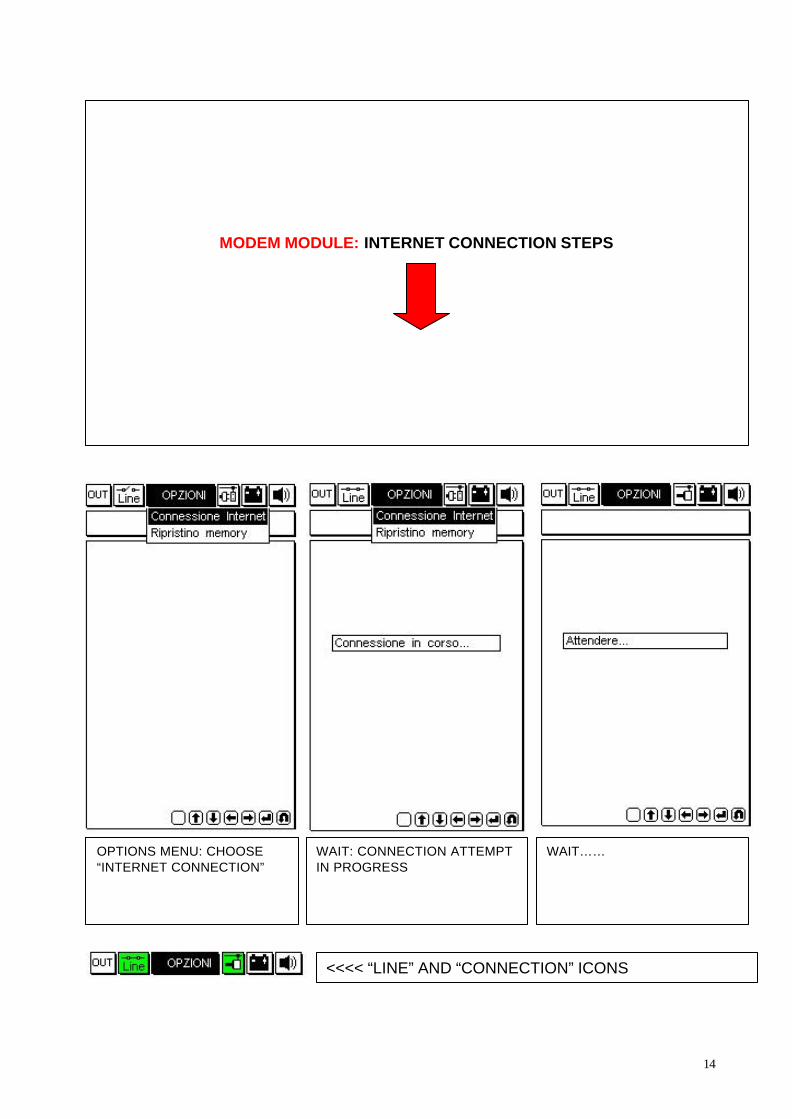
OPTIONS MENU: CHOOSE“INTERNET CONNECTION”
WAIT: CONNECTION ATTEMPTIN PROGRESS
WAIT……
<<<< “LINE” AND “CONNECTION” ICONS
MODEM MODULE: INTERNET CONNECTION STEPS

15
Connection activated, at thespeed indicated above.The system is detecting theavailable updated programs.
These are the updatedprograms detected.Choose the desiredprogram, e.g. self-diagnosisprogram in this case.
“FTP” SERVERCONNECTION INPROGRESS
AUTHORIZATION CHECK SELECTED UPDATEDPROGRAM DOWNLOAD
DOWNLOADSUCCESSFULLYCOMPLETED
Press any key
16
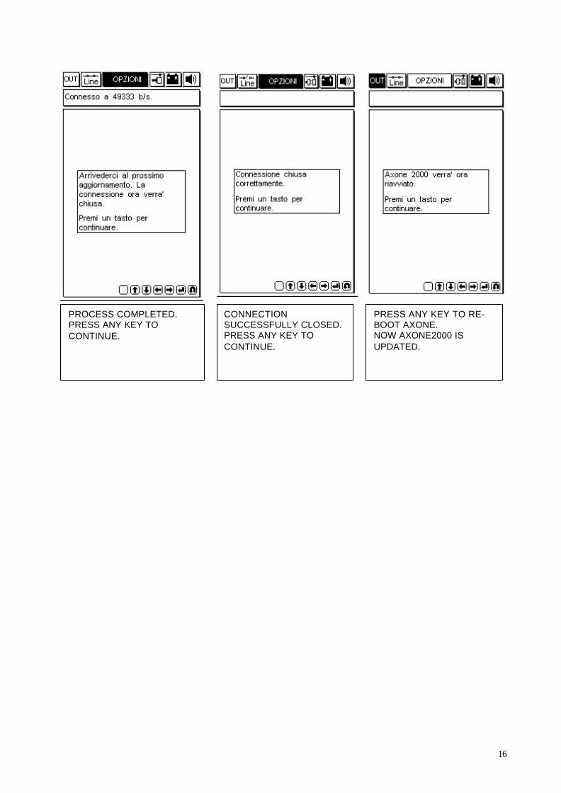
PROCESS COMPLETED.PRESS ANY KEY TOCONTINUE.
CONNECTIONSUCCESSFULLY CLOSED.PRESS ANY KEY TOCONTINUE.
PRESS ANY KEY TO RE-BOOT AXONE.NOW AXONE2000 ISUPDATED.

17
DIAGNOSIS
ACQ MODULE REQUIRED. Switch AXONE2000 off andinsert the ACQ module.
“DIAGNOSIS” function allows to perform a physical analisysof the signals transmitted to the ECU by the various elementsconnected to it: sensors (input signals) and actuators (outputsignals).The operations are on-screen guided and are available forvarious Aprilia models.
Available models:HABANA 50LEONARDO 125 C.D.I.RSVMilleSCARABEO 50SR 50 DITECHSR 50 air cooledSR 50 L.C.
ICONS – LEGENDA
1. OUT KEY = EXIT TO MAIN MENU2. CHECKERED FLAG = test’s start /
finish signal3. OPTIONS MENU = SELECTS THE
AVAILABLE TEST TYPES4. ANIMATED ICON = allows to check if
the program is active5. BATTERY = starts blinking when the
internal battery runs out of charge6. ACOUSTIC SIGNAL KEY =
ENABLES OR DISABLES THEINTERNAL BEEPER
7. OPTIONS WINDOW = shows thepossible choices
8. ECU ICON = shows the selectedinjection system
9. MODEL ICON = shows the selectedvehicle’s model
10. BRAND ICON = shows the selectedvehicle’s brand
5
Use the horizontal arrows keys ß à tonavigate the upper bar

18
TEST PROCEDURE
<<<< choose the model scrolling the models’ choices with thevertical arrows keys.Confirm pressing ENTER.
Select the system to check (starting / charging system,ignition system, injection / ignition system) and confirmwith ENTER.
Confirm the test’s startpressing ENTER.
Choose the signal to analise with the vertical arrows keys,then confirm pressing ENTER.
Signal to be tested

19
4-CHANNELS ACQUISITION CABLE REQUIRED.
USE THE PLUNGER SUPPLIED FOR PLUS ENDCONNECTION (USE CHANNEL 1)THE MINUS END CONNECTION IS GIVEN BY THEGROUND CONNECTION OF THE BLACKBATTERY-CONNECTION PLIER.
The correct connection is indicated on the screen witha drawing and eventually a pin number.
CHANNEL 1
“SIV” (Signal Information Viewing”) TEST PROCEDURE
The available tests with this kind of diagnosis are “user friendly”:
- The different tests become available only if the signal of the device to analise iscompatible with the specific test.
- The signal is compared with treshold values that are stored in AXONE2000 memorycard for every selectable model. If the signal passes the treshold value is consideredan error and an acoustic alarm sounds.
STANDARD “SIV” TESTS AND GENERAL USE SPECS:
• STARTUP LEVEL àà views the signal’s curve and detects wrong signal values in thecritical engine startup phase.
• LINEARITY àà views the signal’s curve and checks the signal’s linearity.
• MIN / MED / MAX àà views the signal’s curve and stores the minimum / medium /maximum values reached.
• MISSED SIGNALS AT STARTUP àà counts the missed signals through the suddenfrequency variations (example: magnetic sensors or “Hall” sensors diagnosis).

20
Choose one of the available“SIV” tests.Confirm with ENTER.
TEST TYPE:1. Single (one single screenshot of acquisition)2. Continous (continous acquisition)Make a choice then press ENTER.The test begins.
>> OSCILLOSCOPE SCREENSHOT <<
The dot lines represent the borderlines where thesignal has to be considered normal for the selectedvehicle. The vehicle’s data are already stored inAXONE2000’s memory card. Every time the signalpasses the borderlines, an error is registered.
SINGLE ACQUISITION: the test stops with only onegraphic screenshotCONTINOUS ACQUISITION: the test stops only if ananomaly is detected. Press ENTER to stop the acquisition.The anomaly is highlighted by an acoustic / visual warningsignal.
21
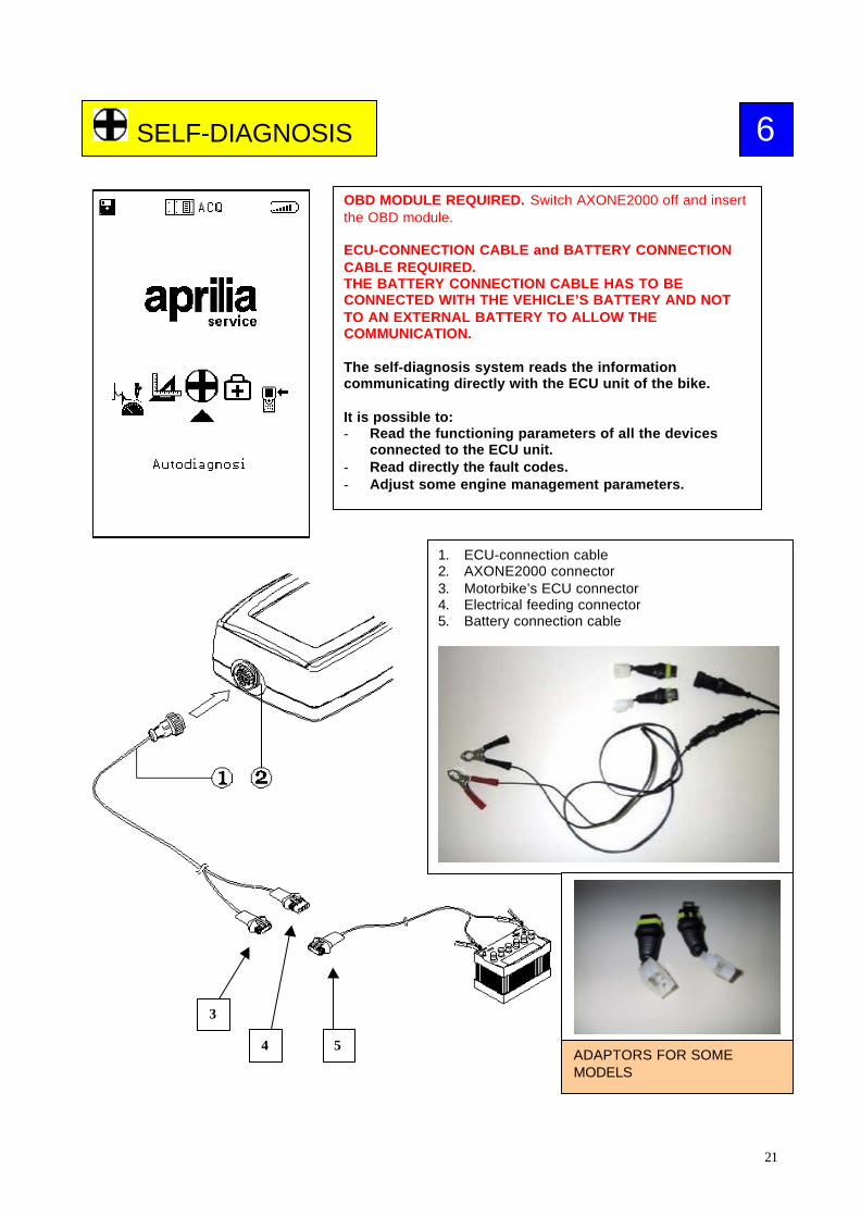
SELF-DIAGNOSIS
OBD MODULE REQUIRED. Switch AXONE2000 off and insertthe OBD module.
ECU-CONNECTION CABLE and BATTERY CONNECTIONCABLE REQUIRED.THE BATTERY CONNECTION CABLE HAS TO BECONNECTED WITH THE VEHICLE’S BATTERY AND NOTTO AN EXTERNAL BATTERY TO ALLOW THECOMMUNICATION.
The self-diagnosis system reads the informationcommunicating directly with the ECU unit of the bike.
It is possible to:- Read the functioning parameters of all the devices
connected to the ECU unit.- Read directly the fault codes.- Adjust some engine management parameters.
3
4 5
1. ECU-connection cable2. AXONE2000 connector3. Motorbike’s ECU connector4. Electrical feeding connector5. Battery connection cable
ADAPTORS FOR SOMEMODELS
6

22
TEST PROCEDURE
Pressing ENTER, an initial blank screenshot appears:
FUNCTION WINDOW:it indicates the selectedfunction
VEHICLE INFO WINDOW:Indicates:vehicle’s brandvehicle’s modelengine typeengine management system
MESSAGES WINDOW:messages for the operator
DIAGNOSIS WINDOW:shows the informationacquired from the ECU.
1. Program exit key (back to main menu)2. Models’ database menu3. Animated icon: indicates the status of communication between
AXONE2000 and vehicle’s ECU. It turns to a “bulb” shaped flashingicon when communication is activated.
4. Battery icon. It starts blinking slowly when battery charge is gettinglow, and blinking quickly when battery charge is over: in this caseAXONE2000 will turn off within 20 seconds.
5. Sound ON / OFF key

23
VEHICLEBRAND’S CHOICE
MODEL’S CHOICESelect one of the available models with thevertical arrows keys. AVAILABLEMODELS: RST futura, ETV caponord,Pegaso i.e., SR 50 DITECH, Atlantic 500,RS 250 (< separate cable required)
ENGINETYPE
OPERATION’S CHOICE:
1. INIEZIONE = SELF-DIAGNOSIS
2. RIPROGRAMMAZIONE= RE-MAPPING
FRAME NUMBER’S FIRST 5DIGITS
INJECTION SYSTEM’SBRAND

24
Turn the key to ONPress ENTER
ECU BOX AND DIAGNOSTICCONNECTOR LOCATION
CONNECT AXONE2000 TOVEHICLE’S ECUTHROUGH THEINDICATED CONNECTOR
CONNECT AXONE2000 TOTHE VEHICLE’S BATTERY
As the communicationbetween AXONE2000 andECU begins, the animatedicon with the “bulb” starts toblink.
An acoustic alarm can turn onif a vehicle’s fault is present inAXONE2000 memory.Go to the FAULTS page tocheck.
The first screenshot viewesECU INDENTIFICATIONDATA
If the communication is notworking, the“COMMUNICATIONINTERRUPTED,REACTIVATE ?” advice willappear.
25
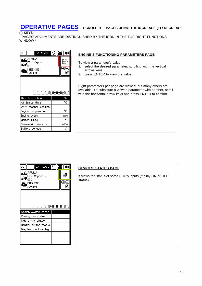
OPERATIVE PAGES – SCROLL THE PAGES USING THE INCREASE (+) / DECREASE
(-) KEYS.* PAGES’ ARGUMENTS ARE DISTINGUISHED BY THE ICON IN THE TOP RIGHT FUNCTIONS’WINDOW *
ENGINE’S FUNCTIONING PARAMETERS PAGE
To view a parameter’s value:1. select the desired parameter, scrolling with the vertical
arrows keys2. press ENTER to view the value
Eight parameters per page are viewed, but many others areavailable. To substitute a viewed parameter with another, scrollwith the horizontal arrow keys and press ENTER to confirm.
DEVICES’ STATUS PAGE
It views the status of some ECU’s inputs (mainly ON or OFFstatus)
26
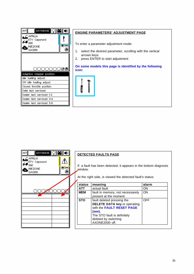
ENGINE PARAMETERS’ ADJUSTMENT PAGE
To enter a parameter adjustment mode:
1. select the desired parameter, scrolling with the verticalarrows keys
2. press ENTER to start adjustment
On some models this page is identified by the followingicon:
DETECTED FAULTS PAGE
If a fault has been detected, it appears in the bottom diagnosiswindow.
At the right side, is viewed the detected fault’s status:
status meaning alarmATT actual fault ONMEM fault in memory, not necessarely
present at the momentON
STO fault deleted pressing theDELETE DATA key or operatingwith the FAULT RESET PAGE(see).The STO fault is definitelydeleted by switchingAXONE2000 off.
OFF
27
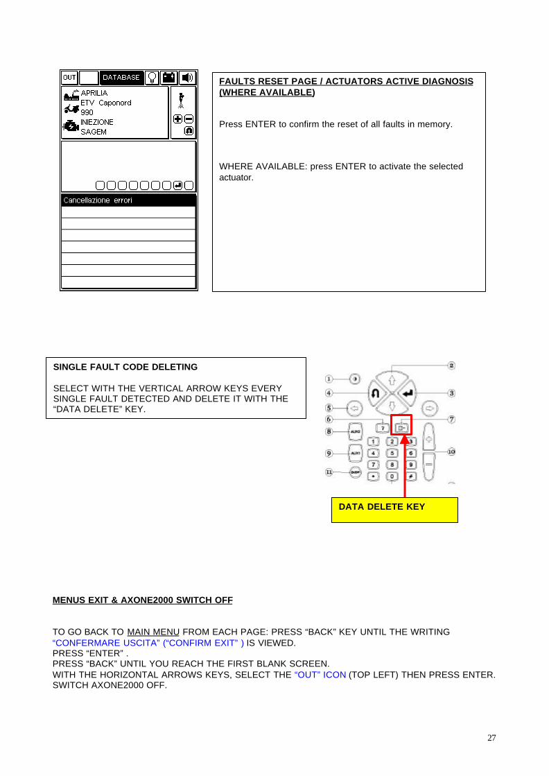
MENUS EXIT & AXONE2000 SWITCH OFF
TO GO BACK TO MAIN MENU FROM EACH PAGE: PRESS “BACK” KEY UNTIL THE WRITING“CONFERMARE USCITA” (“CONFIRM EXIT” ) IS VIEWED.PRESS “ENTER” .PRESS “BACK” UNTIL YOU REACH THE FIRST BLANK SCREEN.WITH THE HORIZONTAL ARROWS KEYS, SELECT THE “OUT” ICON (TOP LEFT) THEN PRESS ENTER.SWITCH AXONE2000 OFF.
FAULTS RESET PAGE / ACTUATORS ACTIVE DIAGNOSIS(WHERE AVAILABLE)
Press ENTER to confirm the reset of all faults in memory.
WHERE AVAILABLE: press ENTER to activate the selectedactuator.
SINGLE FAULT CODE DELETING
SELECT WITH THE VERTICAL ARROW KEYS EVERYSINGLE FAULT DETECTED AND DELETE IT WITH THE“DATA DELETE” KEY.
DATA DELETE KEY

28
7 MEASUREMENTS
MULTI-METER OSCILLOSCOPE
INSERT ACQ MODULE WITH AXONE SWICHED OFF.
< Select “Measures” icon
29
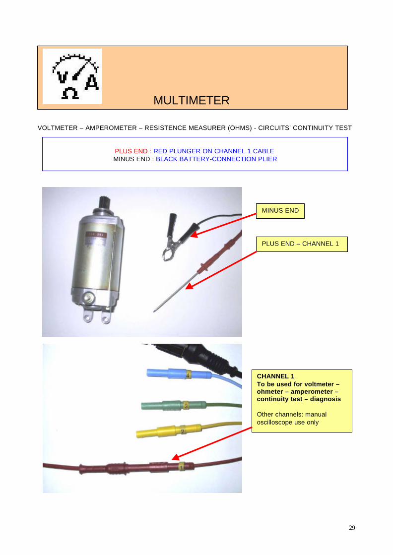
VOLTMETER – AMPEROMETER – RESISTENCE MEASURER (OHMS) - CIRCUITS’ CONTINUITY TEST
MULTIMETER
PLUS END : RED PLUNGER ON CHANNEL 1 CABLEMINUS END : BLACK BATTERY-CONNECTION PLIER
MINUS END
PLUS END – CHANNEL 1
CHANNEL 1To be used for voltmeter –ohmeter – amperometer –continuity test – diagnosis
Other channels: manualoscilloscope use only
30
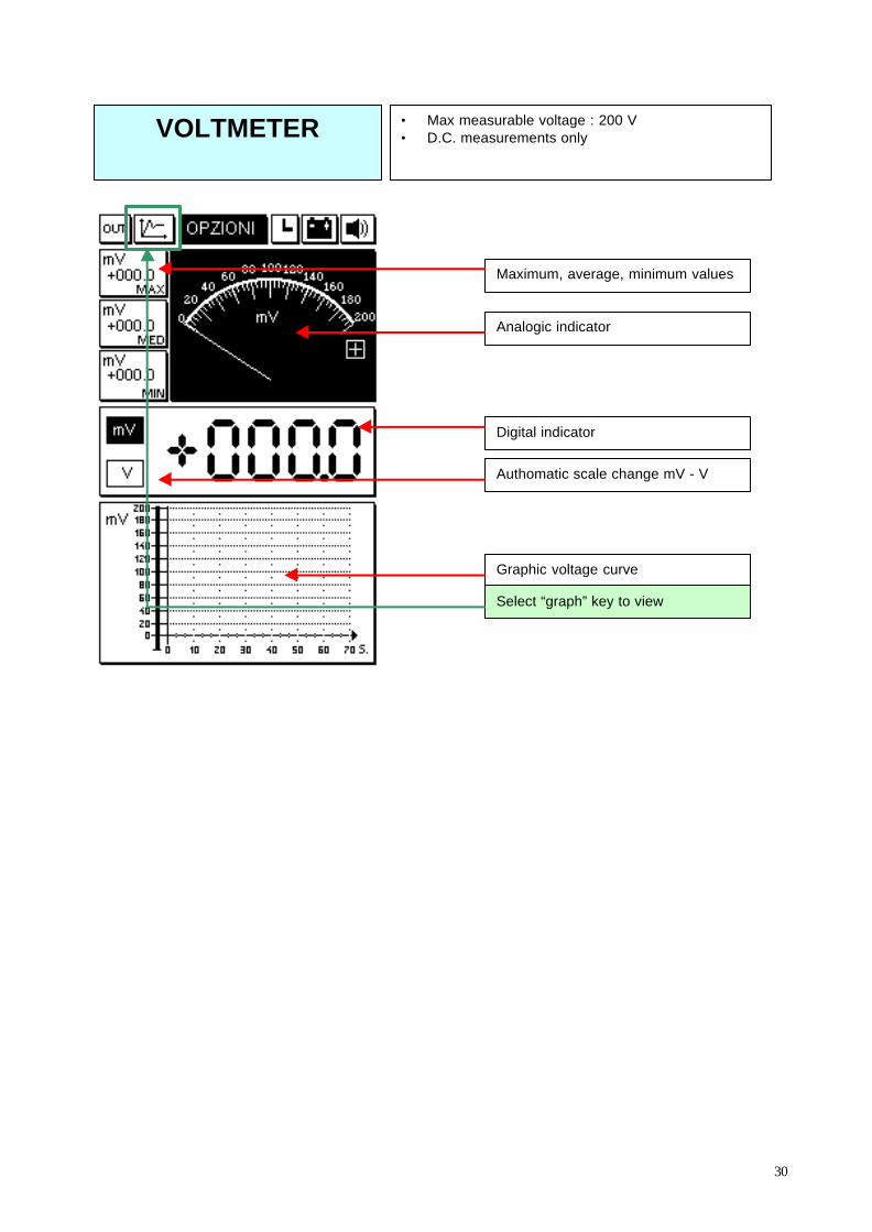
VOLTMETER • Max measurable voltage : 200 V• D.C. measurements only
Maximum, average, minimum values
Analogic indicator
Digital indicator
Graphic voltage curve
Authomatic scale change mV - V
Select “graph” key to view

31
AMPEROMETER • Included cables : max measurable current : 2 A• For currents up to 600 A : BICOR plier (not
included)• D.C. measurements only
Maximum, average, minimum values
Analogic indicator
Digital indicator
Graphic current curve
Authomatic scale change mA - A
Select “graph” key to view
EXAMPLE of BICOR plier installation : choose “BICORplier” option instead of “Amperometer” option from theOPTIONS menu.Select the full-scale at 20 A or 600 A.
This optional device is not included in the AXONE2000 kit.
EXAMPLE OF USE
The end-scale of 2 Amp is enough to detectany residual current that can discharge thevehicle’s battery when engine’s off.
32
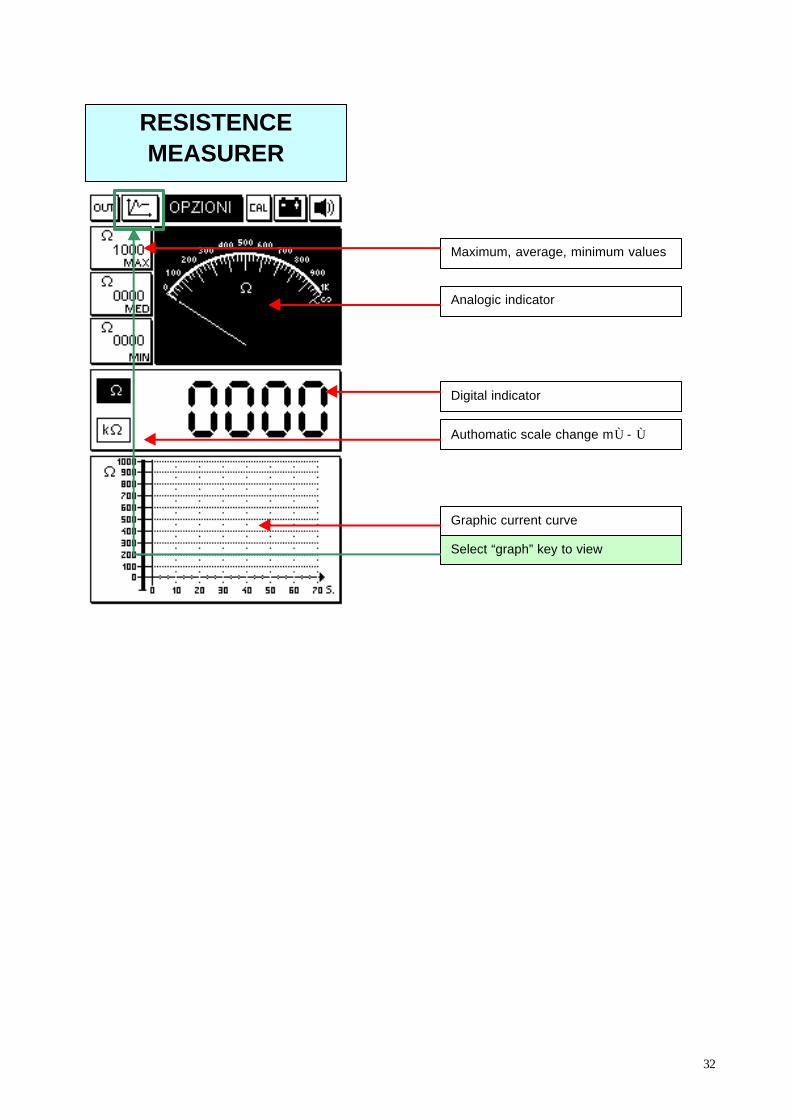
RESISTENCEMEASURER
Maximum, average, minimum values
Analogic indicator
Digital indicator
Graphic current curve
Authomatic scale change mÙ - Ù
Select “graph” key to view

33
MEASUREMENT PROGRAM EXIT
Select “OUT” key on the top left of the screen and confirming pressing “ENTER”
CONTINUITY TEST
CIRCUIT INTERRUPTION / CONTINUITY SYMBOL

34
>> TO START ACQUISITION: SELECT THE “CHECKERED FLAG” KEY AND PRESS ENTER
MANUAL OSCILLOSCOPE
OPTIONS MENU
Chosen channelicon.4 channelsavailable : 1,2,3and 4corrensponding tothe four coloredcables.All acquisitionchannels arereferred to theblack plier of thebatteryconnection cable(minus end).
ACQUISITIONSTART / STOPKEY Signals’ memorization icon
Signal’s scale adjustmentkeys
Reading options:Direct Current /Alternate Current
EXIT: back to mainmenu
Synchronicity: manual/ external / internal(wave signalstabilization)
Values window: viewesthe values read by thecursors on the graph
DISPLAY
4 CHANNELS
35
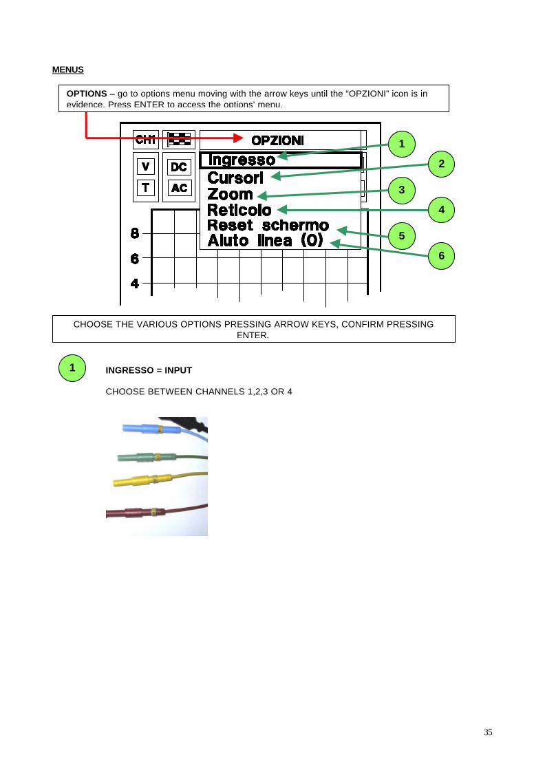
MENUS
CHOOSE THE VARIOUS OPTIONS PRESSING ARROW KEYS, CONFIRM PRESSINGENTER.
6
1
2
3
4
5
1 INGRESSO = INPUT
CHOOSE BETWEEN CHANNELS 1,2,3 OR 4
OPTIONS – go to options menu moving with the arrow keys until the “OPZIONI” icon is inevidence. Press ENTER to access the options’ menu.

36
2 CURSORI = CURSORS
Select on window (1) with arrow keys point A or B.Move the points on the graph with the arrow keys.On the window are viewed:
Va àà voltage point AVb àà voltage point BDv àà voltage difference between A and BDt àà time interval between A and B
1
37
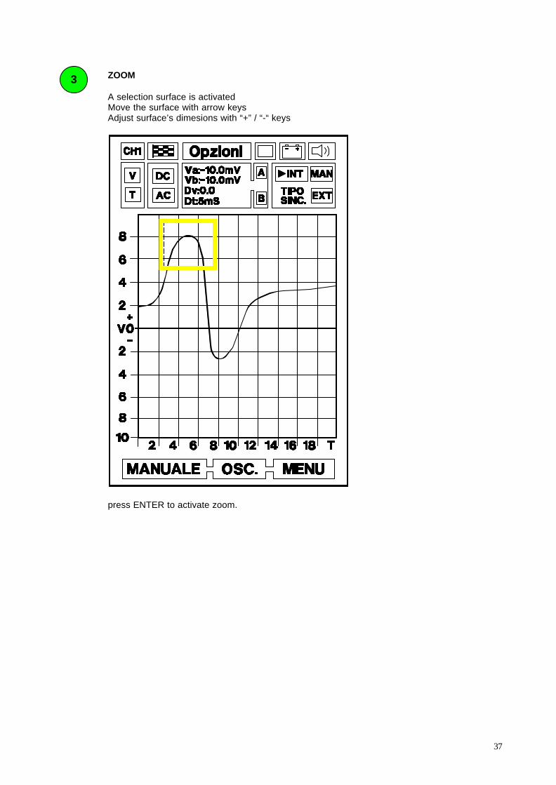
3 ZOOM
A selection surface is activatedMove the surface with arrow keysAdjust surface’s dimesions with “+” / “-“ keys
press ENTER to activate zoom.

38
4 RETICOLO = DISPLAY GRID
You can add / remove the display grid from the screen
5 RESET SCHERMO = SCREEN RESET
Pressing ENTER, the graphs viewed on the screen will be deleted
6 AIUTO LINEA (0) = ZERO-LINE SETTING HELP
This HELP page describes the operations to move the zero-voltage-line on the screen toview the complete signal.
Press LEFT ARROW to return to the graph screen.
During the signal’s acquisition the zero-voltage-line is adjustable pressing “+” / “-“ keys.
39
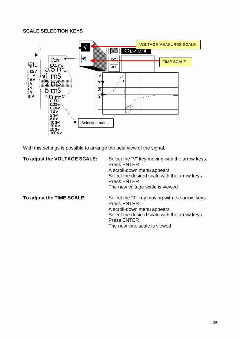
SCALE SELECTION KEYS
With this settings is possible to arrange the best view of the signal.
To adjust the VOLTAGE SCALE: Select the “V” key moving with the arrow keys.Press ENTERA scroll-down menu appearsSelect the desired scale with the arrow keysPress ENTERThe new voltage scale is viewed
To adjust the TIME SCALE: Select the “T” key moving with the arrow keys.Press ENTERA scroll-down menu appearsSelect the desired scale with the arrow keysPress ENTERThe new time scale is viewed
Selection mark
VOLTAGE MEASURES SCALE
TIME SCALE
40
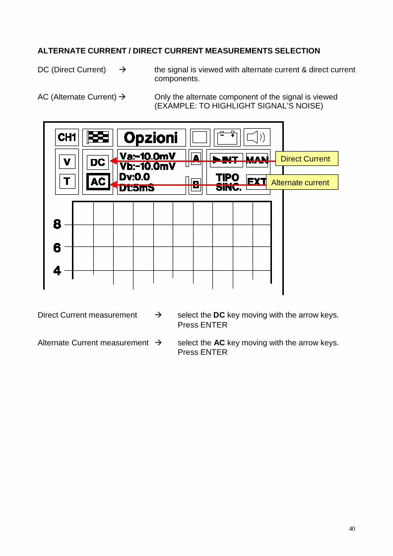
ALTERNATE CURRENT / DIRECT CURRENT MEASUREMENTS SELECTION
DC (Direct Current) à the signal is viewed with alternate current & direct currentcomponents.
AC (Alternate Current) à Only the alternate component of the signal is viewed(EXAMPLE: TO HIGHLIGHT SIGNAL’S NOISE)
Direct Current measurement à select the DC key moving with the arrow keys.Press ENTER
Alternate Current measurement à select the AC key moving with the arrow keys.Press ENTER
Direct Current
Alternate current

41
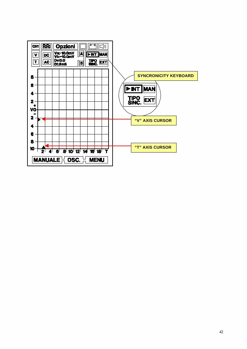
WAVE SIGNAL’S SYNCHRONICITY
The wave form is stabilized thanks to a signal generated by AXONE 2000’s CPU.
INTERNAL SYNCHRONICITY (INT)Synchronisation allows to “freeze” the signal on the screen starting from a certain level ofvoltage amplitude (signal’s link in amplitude). The signal is viewed only over a certain levelof voltage amplitude and always in the same position of the screen.We can also select the signal’s link on the time axis, in order to have the horizontalcentering of the signal on the screen.
Procedure à select the INT key moving with the arrow keyspress ENTERadjust the positioning of the two small blinking cursors (one for the “V”axis, one for the “T” axis) with the arrow keys“V” AXIS CURSOR: indicates the link point (polarity and amplitudelevel) of the synchronized signal.“T” AXIS CURSOR: indicates the starting point of the synchronizedsignal, translated to the right in comparison to the standard zeroposition (left of the screen).
EXTERNAL SYNCHRONICITYFunction not available.
MANUAL SYNCHRONICITYSelect the MAN key moving with the arrow keys.Press ENTER to start the signal’s reading.The synchronicity is still the one selected with the INTERNAL SYNCHRONICITY function(see above), but the signal’s reading starts manually pressing ENTER key.Press ENTER again to start a new reading, which will be overlapped to the previous one,alowing the signals’ comparison.
42
SYNCRONICITY KEYBOARD
“V” AXIS CURSOR
“T” AXIS CURSOR