Embed Size (px)
Citation preview
Tikrit Journal of Engineering Sciences (2020) 27 (3): 8-16.
ISSN: 1813-162X (Print) ; 2312-7589 (Online)
Tikrit Journal of Engineering Sciences
available online at: http://www.tj-es.com
Mahmmoud ON, Gaeid KS, Nashi AF, Siddiqui KM. Induction Motor Speed Control with Solar Cell Using MPPT
Algorithm by Incremental Conductance Method. Tikrit Journal of Engineering Sciences 2020; 27(3): 8- 16.
Omer N Mahmmoud 1*
Khalaf S Gaeid 1
Assad F Nashi2
Khadim Moin Siddiqui3
1 Electrical Department/ Engineering
College/Tikrit University/ Tikrit, Iraq
2 Information &Communication
Technology/Middle technology
University
3Electrical Engineering Department,
Babu Banarasi Das National Institute
of Technology and Management,
Lucknow, India
Keywords:
Induction Motor, PV, Maximum Point Power Tracking, DC/DC converter, Speed Controller.
A R T I C L E I N F O
Article history: Received 07 Dec. 2019
Accepted 10 May 2020
Available online 01 July 2020
Tik
rit
Jou
rna
l o
f E
ng
inee
rin
g S
cien
ces
Tik
rit
Jou
rna
l o
f E
ng
inee
rin
g S
cien
ces
Tik
rit
Jou
rnal
of
En
gin
eeri
ng
Sci
ence
s T
ikri
t Jo
urn
al
of
En
gin
eeri
ng S
cien
ces
Induction Motor Speed Control with Solar Cell Using MPPT Algorithm by Incremental Conductance Method A B S T R A C T
In the world, optimizing energy and finding new sources is important because of
the increased consumption that occurred in all aspects of life. Nowadays, the world
suffers of the reduction in the fossil fuel continuously. One solution to this problem
is the sun and the photovoltaic (PV) cell. To get the benefits of PV, the DC/DC
and DC/AC converters and inverters are combined in one set to get the better usage
of these capabilities. Induction motor (IM) is the horsepower in the industry and
will be considered the load in this work. The DC/DC Converter is used for control
of IM speed in combination with maximum power point tracking (MPPT).
Temperature and radiation change constantly over time, and the maximum energy
should be tracked. This follow-up was performed using Incremental Conductance
method (INC). INC is control buck-boost duty cycle converter. We get the best
performance in INC technology and have less effect on the system. This algorithm
uses INC of the MPPT to control half of horse power of IM. The sine pulse width
modulation technique (SPWM) is used with three level inverters. Simulation on the
Three-phase proves the efficiency of the suggested technique.
.
© 2019 TJES, College of Engineering, Tikrit University
DOI: http://doi.org/10.25130/tjes.27.3.02
نقطة أقصى تتبع خوارزمية باستخدام الشمسية الخلايا مع الحثي المحرك سرعة في التحكم
التزايدي التوصيل طريقة للطاقة بواسطة تكريت جامعة/ الهندسة كلية/الكهربائية الهندسة قسم /عمر نافع محمود
، الوسطى التكنولوجيا الجامعة/ والاتصالات المعلومات تكنولوجيا/اسعد فنجان ناشي ، تكريت كلية الهندسة / جامعة /الكهربائيةقسم الهندسة / خلف سلوم كعيد
كنولوجيا في بابو بناراسي/ لكناو / الهندوالت للإدارةد القومي كاظم معين صادق/ قسم الهندسة الكهربائية/ المعه
الخلاصة العالم يعاني الحاضر، الوقت في. الحياة جوانب جميع في حدث الذي المتزايد الاستهلاك بسبب مهمًا أمرًا جديدة مصادر وإيجاد الطاقة تحسين يعد العالم، في
محولات دمج يتم الكهروضوئية، الخلية فوائد على للحصول. الكهروضوئية والخلية الشمس هو المشكلة هذه حلول أحد. باستمرار الأحفوري الوقود انخفاض من
*Corresponding author: E-mail: [email protected]
8
Omer N Mahmmoud, Khalaf S Gaeid, Assad F Nashi, Khadim Moin Siddiqui/ Tikrit Journal of Engineering Sciences (2020) 27(4): 8-16.
المحرك . القدرات لهذه الأفضل الاستخدام على للحصول واحدة مجموعة في والعاكس المتناوب التيار/المستمر التيار ومحولات المستمر التيار/المستمر التيار
مع الحثي المحرك سرعة في للتحكم المستمر التيار/المستمر التيار محول يستخدم. العمل هذا في الحمل اعتباره وسيتم الصناعة في الحصانية القوة هو الحثي
باستخدام المتابعة هذه إجراء تم. القصوى الطاقة تتبع يجب ولهذا الوقت، بمرور باستمرار والإشعاع الحرارة درجة تتغير. الطاقة نقطة لتتبع الأقصى الحد
التوصيل تكنولوجيا في أداء أفضل على نحصل. للجهد الرافع الخافض للمبدل التشغيل فترة قيمة في تتحكم التزايدي التوصيل طريقة. التزايدي التوصيل طريقة
وتقنية حصان نصف القوة ذو الحثي المحرك في للتحكم القصوى الطاقة نقطة لتتبع التزايدي التوصيل خوارزمية تستخدم. النظام على أقل تأثير ولديه التزايدي
المقترحة. التقنية كفاءة الطور ثلاثي الحثي المحرك على المحاكاة تثبت. مستويات ثلاث ذو عاكس مع المستخدمة الجيبية النبضة عرض تعديل
.
1. INTRODUCTION
Life-style development begins with maintaining
power generation. One strategy to do that is the sunlight
and the semiconductor materials capacities to convert the
DC sunlight into useful power used in the industry,
domestic and military purpose through Photovoltaic (PV)
implementation system [1]. MPPT technologies are
categorized according to speed, digital or analog, sensors,
simplicity, cost and many other parameters [2]-[3].
Control doubly-fed asynchronous generator
electromagnetic torque with different loads with the
MPPT [4].
The Benefits of photovoltaic panel are reduction of
the pollution, green energy, lower cost and maintenance
due to unmovable parts found in PV panel [5]-[6]. MPPT
with Split converter for IM is used in [7]. In [8], improved
INC technology it is found that it quickly detects
increased radiation and makes the right decision, ignores
the approximate value of steady-state fluctuation,
reduces energy loss and has a high efficiency. INC
technology is more efficient and provides fast tracking
speed for MPPT for PV [9]. Combining the INC and the
PID algorithms in [10]. The algorithm can monitor the
MPP point easily, the fluctuation is quite a small
combination of switched reluctance four-phase motor
drive with split converter for both DC and AC source to
charge [11].
As is known, it is affected by the energy extracted
from the solar panels strongly on three factors: the
radiation levels, ambient temperature, characteristics of
the pregnancy [12]. In general, photovoltaic systems
were designed to produce maximum available energy
regardless of radiation density and temperature
impedance to pregnancy determines the energy produced
by solar panels and can be a DC payload with batteries or
without it. When we connect solar panel directly to the
load, the point will be off the system when the point of
intersection of the curve I-V with Load Line, which may
not be at the maximum point of energy, leading to energy
loss. In order to improve the output power of solar panel
and overcome these limitations, DC-DC converter is
embedded between the load and solar panel [13].
In order to optimize the use of solar energy, the PV
must operate at point power in maximum. There are
many techniques for MPPT that have been mentioned in
the literature [14], like incremental conductance (INC),
perturb and observation (P&O), open-circuit voltage
(OCV), short-circuit current (SCC), fuzzy logic and
neural network.
When INC is applied with rapid changes in weather
conditions, the oscillations across M in INC are much
lower compared to P&O [15]. This article discusses the
results of the proposed system, which consists of PV
modeling, MPPT algorithms and IM speed control.
2. MPPT ALGORITHMS
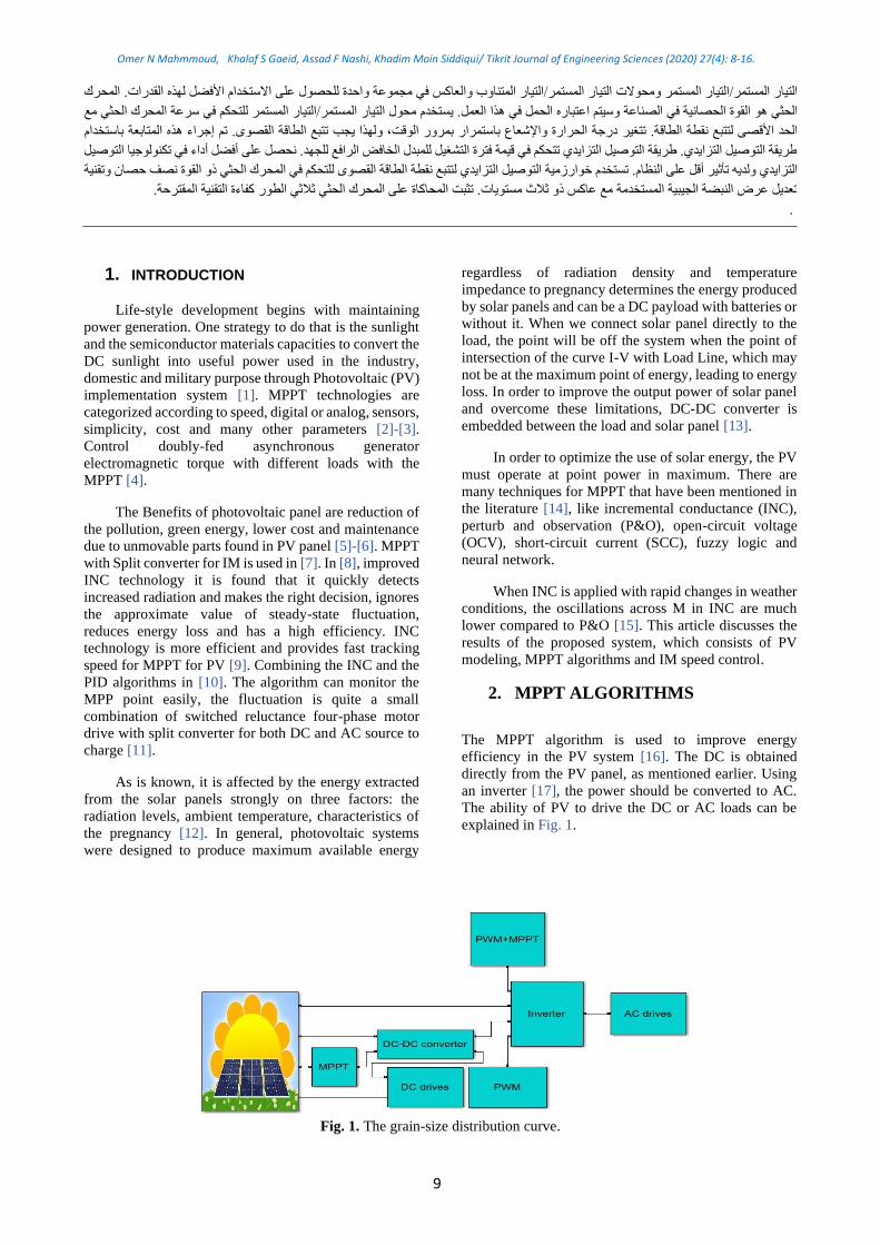
The MPPT algorithm is used to improve energy
efficiency in the PV system [16]. The DC is obtained
directly from the PV panel, as mentioned earlier. Using
an inverter [17], the power should be converted to AC.
The ability of PV to drive the DC or AC loads can be
explained in Fig. 1.
Fig. 1. The grain-size distribution curve.
9

The on-line, off-line and hybrid techniques are the most
main MPPT schemes to ensure better operation of PV
systems. Fig. 2 illustrates the classification of MPPT
methods.
Fig. 2. Classification of MPPT methods
There are two main MPPT online methods [18], the
methods are incremental conductance (INC) [19], and
Perturbation and Observation [20]. This work used INC
method it's shown in Fig. 3.
Fig. 3. PWM generation technique
The INC principle is based on the premise that the power
derivative on voltage derivative of PV output equals zero.
The output of this algorithm is almost efficient under
rapid switching conditions, MPP approaches to the left
when PV radiation is reduced. In terms of performance,
this technology is known to be one of the better
innovations, but its cost is high and its control circuit is
complex. Normally, MPPT failed to track sunlight for
many reasons. The best performance specifications of the
MPPT system are to obtain sufficient tracking of
accuracy, speed, low steady state error and high
efficiency [21]. DC-DC converters are classifying as a
Luo converter, SEPIC buck, boost, buck-boost, Cuk,
Zeta, Forward, push-pull, full bridge, and fly back
converter [22]. Two MPPT algorithms with recent
cuckoo search and particle swarm optimization used in
[23]. The operation of PV panels in the shaded
environments can lead to reduction in the power
generation output and hence the MPPT will not lead to
efficient results [24]. In [25], the advanced techniques
with control systems, books, Simulink implementation of
PV systems is given and the classical techniques as well.
A simple comparison of the MPPT techniques may be
made in Table 1.
MPPT by INC technique the ratio of the derived PV
power in relation to the derived voltage is zero which is
given in (1) [26].
dP/dV = 1 (1)
Where:
P = V*I (2)
d(V*I)/dV = I+V*dI/dV = 0 (3)
dI/dV = -I/V (4)
VIdVdI // −=
Where:
dI, dV is the harmonic components of current (I) and
voltage (V) ripples of MPPT
I, V is the average voltage (V) and current (I) values for
MPPT
The error is measured as in (5) dI/dV+ I/V≈ 0 (5)
Then, the regulator output is the duty cycle
correction to control the system.
10
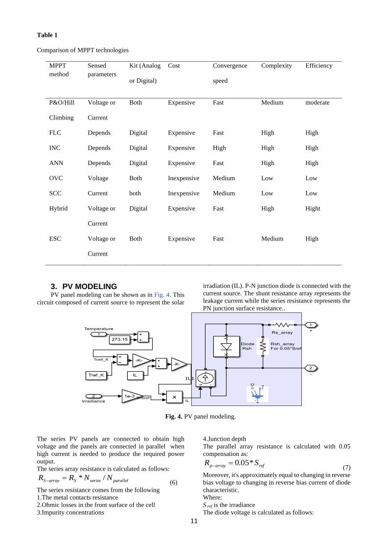
Table 1
Comparison of MPPT technologies
MPPT
method
Sensed
parameters
Kit (Analog
or Digital)
Cost Convergence
speed
Complexity Efficiency
P&O/Hill
Climbing
Voltage or
Current
Both Expensive Fast Medium moderate
FLC Depends Digital Expensive Fast High High
INC Depends Digital Expensive High High High
ANN Depends Digital Expensive Fast High High
OVC Voltage Both Inexpensive Medium Low Low
SCC Current both Inexpensive Medium Low Low
Hybrid Voltage or
Current
Digital Expensive Fast High Hight
ESC Voltage or
Current
Both Expensive Fast Medium High
3. PV MODELING PV panel modeling can be shown as in Fig. 4. This
circuit composed of current source to represent the solar
irradiation (IL). P-N junction diode is connected with the
current source. The shunt resistance array represents the
leakage current while the series resistance represents the
PN junction surface resistance..
Fig. 4. PV panel modeling.
The series PV panels are connected to obtain high
voltage and the panels are connected in parallel when
high current is needed to produce the required power
output.
The series array resistance is calculated as follows:
parallelseriesSarrayS NNRR /*=− (6)
The series resistance comes from the following
1.The metal contacts resistance
2.Ohmic losses in the front surface of the cell
3.Impurity concentrations
4.Junction depth
The parallel array resistance is calculated with 0.05
compensation as:
refarrayp SR *05.0=− (7)
Moreover, it's approximately equal to changing in reverse
bias voltage to changing in reverse bias current of diode
characteristic.
Where:
S ref is the irradiance
The diode voltage is calculated as follows:
11
Omer N Mahmmoud, Khalaf S Gaeid, Assad F Nashi, Khadim Moin Siddiqui/ Tikrit Journal of Engineering Sciences (2020) 27(4): 8-16.
𝑉𝑑𝑖𝑜𝑑𝑒 = 𝑉𝑝𝑣 + 𝑅𝑠𝐼𝑝𝑣 (8)
The diode characteristic, which depends on various
variables give it the nonlinearity characteristic is given in
(9)
𝐼𝑑𝑖𝑜𝑑𝑒 = 𝐼𝑜𝑢𝑡 ∗ [𝐸𝑥𝑝(𝑉𝑑𝑖𝑜𝑑𝑒/𝑉𝑇) − 1] (9)
Where:
I out is the current which flows on reverse direction when
the diode is reverse biased. It's called the saturation
current or leakage current.
VT is the temperature voltage and it is can be illustrated
as in (10)
𝑉𝑇 = 𝐾 ∗ 𝑇𝑝𝑣_𝑐𝑒𝑙𝑙/ 𝑞 ∗ 𝑁𝐼𝑑𝑒𝑛𝑡∗𝑁𝑐𝑒𝑙𝑙𝑠 ∗ 𝑁𝑠𝑒𝑟𝑖𝑒𝑠 (10)
Where:
NIdent is the ideality factor for a diode and it is an indicator
of the behavioral proximity of the device under test, to an
ideal diode.
q=1.6e-19C is the electron charge,
K=1.38e-23 j/k is the Boltzmann’s constant.
The load current expressed in the (11)
𝐼𝐿 =𝑆
𝑆𝑟𝑒𝑓∗ (𝐼𝐿_𝑅𝑒 𝑓 + 𝛼 ∗ (𝑇𝑝𝑣 − 𝑇𝑟𝑒𝑓), 𝛼 = 0.001 (11)
The voltage generated by PV cells and the current are
expressed in (12):
𝑉𝑔 = 𝐼𝑔𝑅𝑠(𝑁𝑠/𝑁𝑝)𝑙𝑖𝑛(1 +𝑁𝑝𝐼𝑝ℎ−𝐼𝑔
𝑁𝑝𝐼𝑜) (12)
𝐼𝑔 = 𝐼𝑝ℎ − 𝐼𝑜(𝐸𝑥𝑝( 𝑞𝑉𝑔/ 𝑘𝑇) − 1) (13)
From (13), set Vg = 0 in the exponential expression, hence
the short circuit current can be obtained as:
𝐼𝑠𝑐 = 𝐼𝑝ℎ (14)
The voltage of the open circuit is obtained by equating t
he cell current to zero, expressed in (15).
𝑉𝑜𝑐 = (𝑘𝑇/𝑞)𝑙𝑖𝑛(𝐼𝑝ℎ+𝐼𝑜
𝐼𝑜) ≅ (𝑘𝑇/𝑞)𝑙𝑖𝑛(
𝐼𝑝ℎ
𝐼𝑜) (15)
In this equation the value of Iph >> Io
The PV cell's MPP, expressed in (16):
𝑃𝑚 = 𝐼𝑚𝑉𝑚 = 𝐹𝐹 ∗ 𝐼𝑠𝑐𝑉𝑠𝑐 (16)
where:
FF, Im, Vm is the fill factor which is the reliability indictor,
maximum current and maximum voltage respectively.
max / theoreticalFF P P= (17)
The PV panels can efficiently be determined as in (18):
𝜂 = 𝑃𝑜𝑢𝑡/𝑃𝑖𝑛
(18)
Where:
Pout, Pin is the input and output power respectively
2
max ( / )outP P W m= (19)
At 1.5 am, Pin = 1000 (W /m2).
4. SPEED CONTROLLERS IM The IM motor drives received great attention in the
various applications [27]. One stage PV system with five
phase IM drive is proposed [28]. The system of PV used
makes conversion of sunlight energy into useful power
through semiconductor materials, known as PV cells
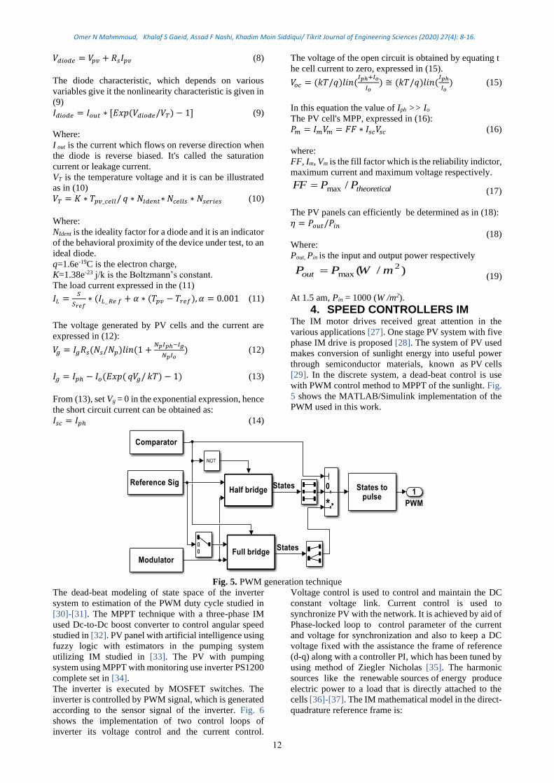
[29]. In the discrete system, a dead-beat control is use
with PWM control method to MPPT of the sunlight. Fig.
5 shows the MATLAB/Simulink implementation of the
PWM used in this work.
Fig. 5. PWM generation technique
The dead-beat modeling of state space of the inverter
system to estimation of the PWM duty cycle studied in
[30]-[31]. The MPPT technique with a three-phase IM
used Dc-to-Dc boost converter to control angular speed
studied in [32]. PV panel with artificial intelligence using
fuzzy logic with estimators in the pumping system
utilizing IM studied in [33]. The PV with pumping
system using MPPT with monitoring use inverter PS1200
complete set in [34].
The inverter is executed by MOSFET switches. The
inverter is controlled by PWM signal, which is generated
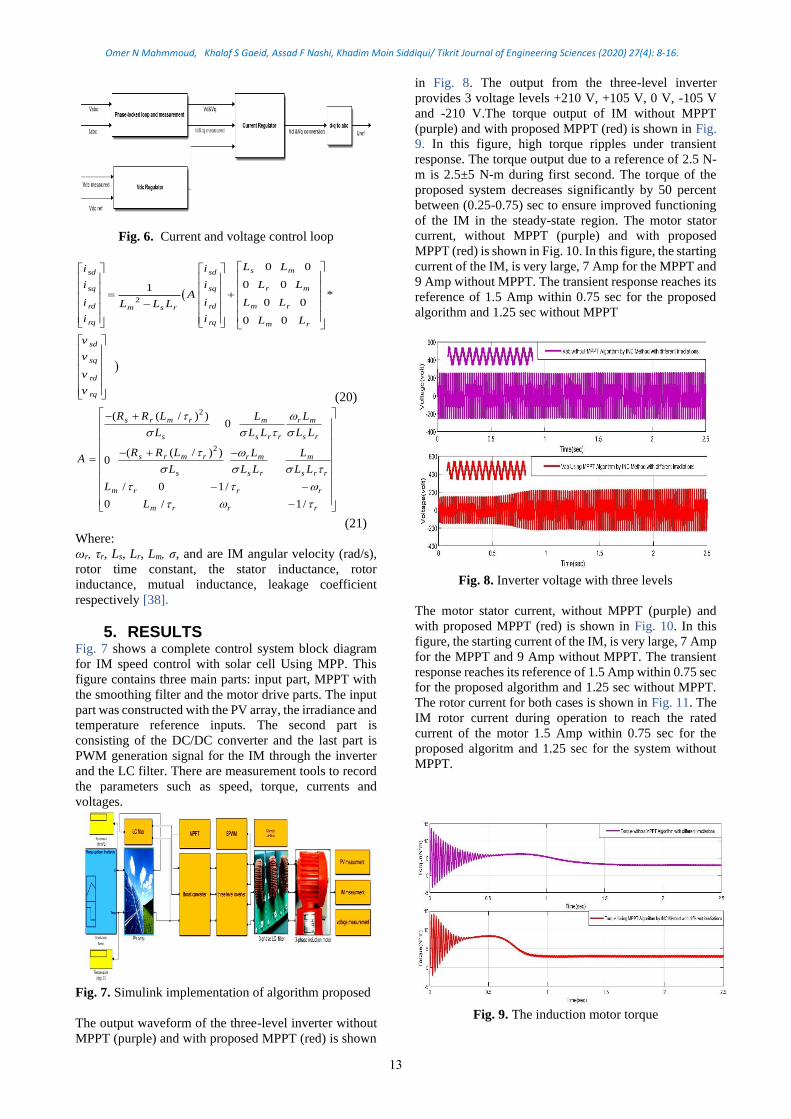
according to the sensor signal of the inverter. Fig. 6
shows the implementation of two control loops of
inverter its voltage control and the current control.
Voltage control is used to control and maintain the DC
constant voltage link. Current control is used to
synchronize PV with the network. It is achieved by aid of
Phase-locked loop to control parameter of the current
and voltage for synchronization and also to keep a DC
voltage fixed with the assistance the frame of reference
(d-q) along with a controller PI, which has been tuned by
using method of Ziegler Nicholas [35]. The harmonic
sources like the renewable sources of energy produce
electric power to a load that is directly attached to the
cells [36]-[37]. The IM mathematical model in the direct-
quadrature reference frame is:
12
Omer N Mahmmoud, Khalaf S Gaeid, Assad F Nashi, Khadim Moin Siddiqui/ Tikrit Journal of Engineering Sciences (2020) 27(4): 8-16.
Fig. 6. Current and voltage control loop
(
)
2
0 0
0 01*
0 0
0 0
s msd sd
r msq sq
rd rd m rm s r
rq rq m r
sd
sq
rd
rq
L Li i
L Li iA
i i L LL L L
i i L L
v
v
v
v
= + −
(20)
2
2
( ( / ) )0
( ( / ) )0
/ 0 1/
0 / 1/
s r m r m r m
s s r r s r
s r m r r m m
s s r s r r
m r r r
m r r r
R R L L L
L L L L L
R R L L LA
L L L L L
L
L
− +
− + − =
− − −
(21)
Where:
ωr, τr, Ls, Lr, Lm, σ, and are IM angular velocity (rad/s),
rotor time constant, the stator inductance, rotor
inductance, mutual inductance, leakage coefficient
respectively [38].
5. RESULTS Fig. 7 shows a complete control system block diagram
for IM speed control with solar cell Using MPP. This
figure contains three main parts: input part, MPPT with
the smoothing filter and the motor drive parts. The input
part was constructed with the PV array, the irradiance and
temperature reference inputs. The second part is
consisting of the DC/DC converter and the last part is
PWM generation signal for the IM through the inverter
and the LC filter. There are measurement tools to record
the parameters such as speed, torque, currents and
voltages.
Fig. 7. Simulink implementation of algorithm proposed
The output waveform of the three-level inverter without
MPPT (purple) and with proposed MPPT (red) is shown
in Fig. 8. The output from the three-level inverter
provides 3 voltage levels +210 V, +105 V, 0 V, -105 V
and -210 V.The torque output of IM without MPPT
(purple) and with proposed MPPT (red) is shown in Fig.
9. In this figure, high torque ripples under transient
response. The torque output due to a reference of 2.5 N-
m is 2.5±5 N-m during first second. The torque of the
proposed system decreases significantly by 50 percent
between (0.25-0.75) sec to ensure improved functioning
of the IM in the steady-state region. The motor stator
current, without MPPT (purple) and with proposed
MPPT (red) is shown in Fig. 10. In this figure, the starting
current of the IM, is very large, 7 Amp for the MPPT and
9 Amp without MPPT. The transient response reaches its
reference of 1.5 Amp within 0.75 sec for the proposed
algorithm and 1.25 sec without MPPT
Fig. 8. Inverter voltage with three levels
The motor stator current, without MPPT (purple) and
with proposed MPPT (red) is shown in Fig. 10. In this
figure, the starting current of the IM, is very large, 7 Amp
for the MPPT and 9 Amp without MPPT. The transient
response reaches its reference of 1.5 Amp within 0.75 sec
for the proposed algorithm and 1.25 sec without MPPT.
The rotor current for both cases is shown in Fig. 11. The
IM rotor current during operation to reach the rated
current of the motor 1.5 Amp within 0.75 sec for the
proposed algoritm and 1.25 sec for the system without
MPPT.
Fig. 9. The induction motor torque
13
Omer N Mahmmoud, Khalaf S Gaeid, Assad F Nashi, Khadim Moin Siddiqui/ Tikrit Journal of Engineering Sciences (2020) 27(4): 8-16.
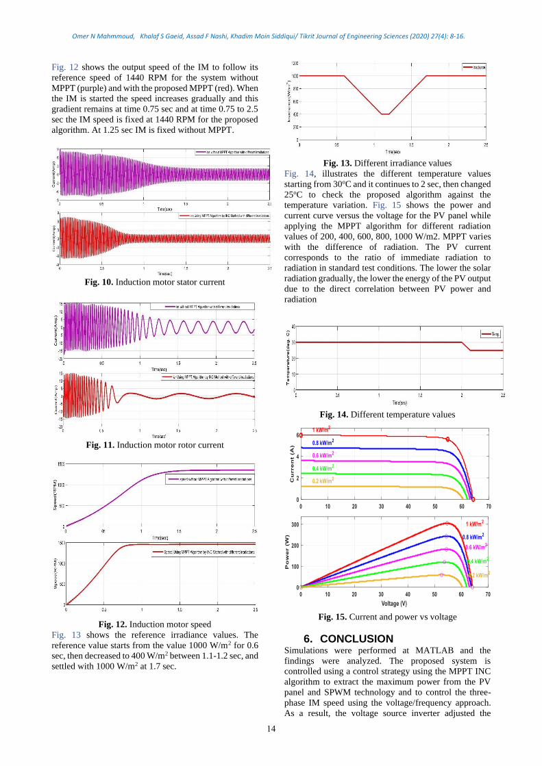
Fig. 12 shows the output speed of the IM to follow its
reference speed of 1440 RPM for the system without
MPPT (purple) and with the proposed MPPT (red). When
the IM is started the speed increases gradually and this
gradient remains at time 0.75 sec and at time 0.75 to 2.5
sec the IM speed is fixed at 1440 RPM for the proposed
algorithm. At 1.25 sec IM is fixed without MPPT.
Fig. 10. Induction motor stator current
Fig. 11. Induction motor rotor current
Fig. 12. Induction motor speed
Fig. 13 shows the reference irradiance values. The
reference value starts from the value 1000 W/m2 for 0.6
sec, then decreased to 400 W/m2 between 1.1-1.2 sec, and
settled with 1000 W/m2 at 1.7 sec.
Fig. 13. Different irradiance values
Fig. 14, illustrates the different temperature values
starting from 30oC and it continues to 2 sec, then changed
25oC to check the proposed algorithm against the
temperature variation. Fig. 15 shows the power and
current curve versus the voltage for the PV panel while
applying the MPPT algorithm for different radiation
values of 200, 400, 600, 800, 1000 W/m2. MPPT varies
with the difference of radiation. The PV current
corresponds to the ratio of immediate radiation to
radiation in standard test conditions. The lower the solar
radiation gradually, the lower the energy of the PV output
due to the direct correlation between PV power and
radiation
Fig. 14. Different temperature values
Fig. 15. Current and power vs voltage
6. CONCLUSION Simulations were performed at MATLAB and the
findings were analyzed. The proposed system is
controlled using a control strategy using the MPPT INC
algorithm to extract the maximum power from the PV
panel and SPWM technology and to control the three-
phase IM speed using the voltage/frequency approach.
As a result, the voltage source inverter adjusted the
14
Omer N Mahmmoud, Khalaf S Gaeid, Assad F Nashi, Khadim Moin Siddiqui/ Tikrit Journal of Engineering Sciences (2020) 27(4): 8-16.
terminal voltage such that the voltage / frequency ratio
remained the same. The maximum torque was observed
to remain constant across the range of speeds. INC have
a good capability to track MPPT, Also, less transient
response time, that is, the IM stability was faster. And the
ripple in speed is lower. The design proposed therefore
increases both the efficiency of the PV source and the IM
by using inverter on three levels.
REFERENCES [1] Jawad Ahmad. A Unified Approach to Maximum
Power Point Tracking and I-V Curve Determination
of Photovoltaic Arrays from Real-time
Measurements. Doctoral Dissertation in Energy
Engineering. University of Polytechnic, Torino,
Italy, 2017.
[2] Atallah AM, Abdelaziz AY, Jumaah RS. A New
Study of Maximum Power Point Tracker Techniques
and Comparison for PV Systems. Tikrit Journal of
Engineering Sciences 2016; 23(1): 69- 77.
[3] Abdulmunem AR, Jadallah AA, Hoshi HA, Jabal
MH. Effect of Colored Filters on PV Panels
Temperature and Performance under Baghdad
Meteorological Condition. Tikrit Journal of
Engineering Sciences 2018; 25(4): 46- 50.
[4] Mensoua S, Essadki A, Nasser T, Idrissi BB, Tarla
LB. Dspace DS1104 implementation of a robust
nonlinear controller applied for DFIG driven by
wind turbine. Renewable Energy 2020; 147 (1):
1759-1771.
[5] Moslehi K, Kumar R. A reliability perspective of the
smart grid. IEEE Trans. on Smart Grid 2010; 1(1):
57-64.
[6] Choudhury S, Dash TP, Bhowmik P, Rout PK. A
novel Control Approach Based on Hybrid Fuzzy
Logic and Seeker Optimization for Optimal Energy
Management between Micro-Sources and Super
Capacitor in an Islanded Micro grid. Journal of King
Saud University - Engineering Sciences 2020; 32(1):
27-41.
[7] Saeed J, Niakinezhad M, Fernando N, Wang L.
Model Predictive Control of an Electric Vehicle
Motor Drive Integrated Battery Charger. IEEE 13th
International Conference on Compatibility, Power
Electronics and Power Engineering (CPE-
POWERENG) 2019, Denmark.
[8] El Ghzizal A, Sebti S, Derouich A. Modeling of
Photovoltaic System with Modified Incremental
Conductance Algorithm for Fast Changes of
Irradiance. Hindawi International Journal of
Photoenergy 2018: 13.
[9] Jain K, Gupta M, Bohre AK. Implementation and
Comparative Analysis of P&O and INC MPPT
Method for PV System. IEEE India International
Conference on Power Electronics (IICPE) 2018,
JAIPUR, India, India.
[10] Youyu Wu, Jibin Li, Chengjun Li. Study of the
improved INC MPPT algorithm for PV systems.
IEEE 3rd International Conference on Control
Science and Systems Engineering 2017, Beijing,
China.
[11] Hu Y, Gan C, Cao W. Li C, Finney SJ. Split
Converter-Fed SRM Drive for Flexible Charging in
EV/HEV Applications. IEEE Transactions on
Industrial Electronics 2015; 62(10): 6085-6095.
[12] Karami N, Moubayed N, Outbib R. General review
and classification of different MPPT Techniques.
Renewable and Sustainable Energy Reviews 2017;
68(1): 1-18.
[13] Anwer AMO, Omar FA, Bakir H, Kulaksiz AA.
Sensorless Control of a PMSM Drive Using EKF for
Wide Speed Range Supplied by MPPT Based Solar
PV System. ELEKTRONIKA IR
ELEKTROTECHNIKA 2020; 26(1): 32-39.
[14] Comparison of Maximum Power Point Tracking
(MPPT) Algorithms to Control DC-DC Converters
in Photovoltaic Systems. Recent Advances in
Electrical & Electronic Engineering 2019; 12(4):
355 – 367.
[15] Basha H, Rani C . Different Conventional and Soft
Computing MPPT Techniques for Solar PV Systems
with High Step-Up Boost Converters: A
Comprehensive Analysis. Energies 2020; 13(2):
371.
[16] Hamdi H, Regaya CB, Zaafouri A. A sliding-Neural
Network Control of Induction Motor Pump Supplied
by Photovoltaic Generator. Protection and Control
of Modern Power Systems 2020; 5(1):1-8.
[17] Ankireddy N, Naik V, Panda A, Tiwary N. A
Comprehensive Review of PV Driven Electrical
Motors. Solar Energy 2020; 195: 278-303.
[18] Faranda R, Leva S. Energy Comparison of MPPT
Techniques for PV Systems. WSEAS Transactions
on Power Systems 2008; 3(5): 446-455.
[19] Fangrui, L. Yong K. Yu Z. Shanxu D. Comparison
of P&O and hill climbing MPPT methods for grid-
connected PV converter. ICIEA: Industrial
Electronics and Applications 2008, Singapore; 804-
807.
[20] Brito MAG, Galotto L, Sampaio LP, Melo GA,
Canesin CA. Evaluation of the main MPPT
techniques for photovoltaic applications. IEEE
Transactions on Industrial Electronics 2013; 60(3):
1156-1167.
[21] Abdel Salam M, EL Mohandes MT, Goda M.
Modern Maximum Power Point Tracking
Techniques for Photovoltaic Energy Systems book
2020: 1-29.
[22] Jeremy LJ, Ooi CA, Teh J. Non-isolated
conventional DC-DC converter comparison for a
photovoltaic system: A review. Journal of
Renewable and Sustainable Energy 2020; 12(1):
013502.
[23] Abo-Elyousr FK, Abdelshafy AM, Abdelaziz AY.
MPPT-Based Particle Swarm and Cuckoo Search
Algorithms for PV Systems. Modern Maximum
Power Point Tracking Techniques for Photovoltaic
Energy Systems book 2019:379-400.
[24] Farh HMH, Eltamaly AM. Maximum Power
Extraction from the Photovoltaic System under
Partial Shading Conditions. Modern Maximum
Power Point Tracking Techniques for Photovoltaic
Energy Systems book 2019:107-129.
15
Omer N Mahmmoud, Khalaf S Gaeid, Assad F Nashi, Khadim Moin Siddiqui/ Tikrit Journal of Engineering Sciences (2020) 27(4): 8-16.
[25] Djamila Rekioua. MPPT Methods in Hybrid
Renewable Energy Systems. Hybrid Renewable
Energy Systems book 2019:79-138.
[26] Khursheed MN, Khan MFN, Ali G, Khan AK. A
Review of Estimating Solar Photovoltaic Cell
Parameters. International Conference on
Computing, Mathematics and Engineering
Technologies (iCoMET) 2019, Sukkur, Pakistan.
[27] . Diab AAZ, Al-Sayed AM, Mohammed HHA,
Mohammed YS. Literature Review of Induction
Motor Drives. Development of Adaptive Speed
Observers for Induction Machine System
Stabilization book. Springer Briefs in Electrical and
Computer Engineering. Springer, 2010:7-18.
[28] Babu YS, Sekhar KC. Battery Assisted, PSO-BFOA
based Single Stage PV Inverter fed Five Phase
Induction Motor Drive for Green Boat Applications.
Intelligent Systems, Technologies and Applications
2010: 227-240.
[29] S BRV, G. Devadhas G. Design and development
of new control technique for standalone PV system.
Microprocessors and Microsystems 2020;72: 20-28.
[30] Mohapatra A, Nayak B, Das P, Mohanty K. A
review on MPPT techniques of PV system under
partial shading condition. Renew. Sust. Energy Rev.
2017: 854-867.
[31] Premila TR. Solar PV array fed BLDC motor using
DC-DC converter. Int. J. Control Theory Appl 2017;
10(25): 43-54.
[32] Linares-Floresa J, Guerrero-Castellanosb JF,
Lescas-Hernándeza R, Hernández-Méndeza A,
Vázquez-Peralesb R. Angular speed control of an
induction motor via a solar powered boost converter-
voltage source inverter combination. Energy 2019;
166(1): 326-334.
[33] Shukla S, Singh B. Adaptive speed estimation with
fuzzy logic control for PV-grid interactive induction
motor drive-based water pumping. IET Power
Electronics 2019; 12(6): 1554-1562.
[34] Abdellahi B, Mohamed M, Dah ND, Diakité A,
Hassen, AE, Ehssein CO. Monitoring the
Performances of a Maximum Power Point Tracking
Photovoltaic (MPPT PV) Pumping System Driven
by A Brushless Direct Current (BLDC) Motor.
International Journal of Renewable Energy
Development 2019; 8(2): 193-201.
[35] Soni YP, Paliwal P, Kira M. Control and
Coordination of grid connected PV Fed Induction
Motor. International Conference on Advances in
Electronics, Electrical & Computational
Intelligence (ICAEEC) 2019, India
[36] J. Klima, Closed-Form Analytical Investigation of
Space-Vector PWM Inverter Fed Induction Motor
Drive under DC-Bus Voltage Pulsation, WSEAS
Transactions on Power Systems 2008; 3(3): 63-75.
[37] Gaeid KS, Ping HW, Mohamed HAF. Indirect
vector control of a variable frequency induction
motor drive (VCIMD). International Conference on
Instrumentation, Communication, Information
Technology, and Biomedical Engineering 2009,
Bandung, Indonesia.
[38] Lindsaya N, Liboisa Q, Badosab J, Migan-Duboisc
A, Bourdind V. Errors in PV power modelling due
to the lack of spectral and angular details of solar
irradiance inputs. Solar Energy 2020; 197: 266-278.
16