Embed Size (px)
Citation preview
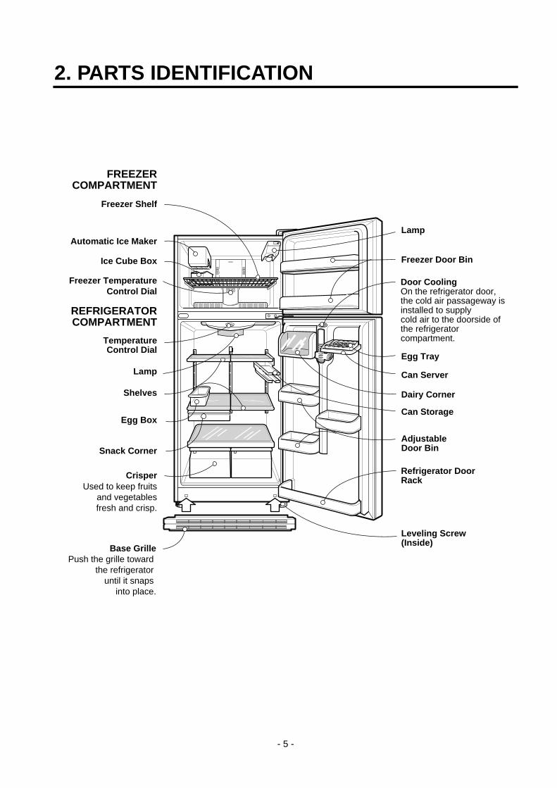
2. PARTS IDENTIFICATION
- 5 -
Automatic Ice Maker
Ice Cube Box
FREEZERCOMPARTMENT
REFRIGERATORCOMPARTMENT
Freezer TemperatureControl Dial
Freezer Shelf
Door CoolingOn the refrigerator door,the cold air passageway isinstalled to supplycold air to the doorside of the refrigeratorcompartment.Temperature
Control Dial
Lamp
Shelves
Egg Box
Snack Corner
CrisperUsed to keep fruits
and vegetablesfresh and crisp.
Freezer Door Bin
Lamp
Refrigerator DoorRack
Can Server
Egg Tray
Can Storage
AdjustableDoor Bin
Leveling Screw(Inside)
Base GrillePush the grille toward
the refrigerator until it snaps
into place.
Dairy Corner
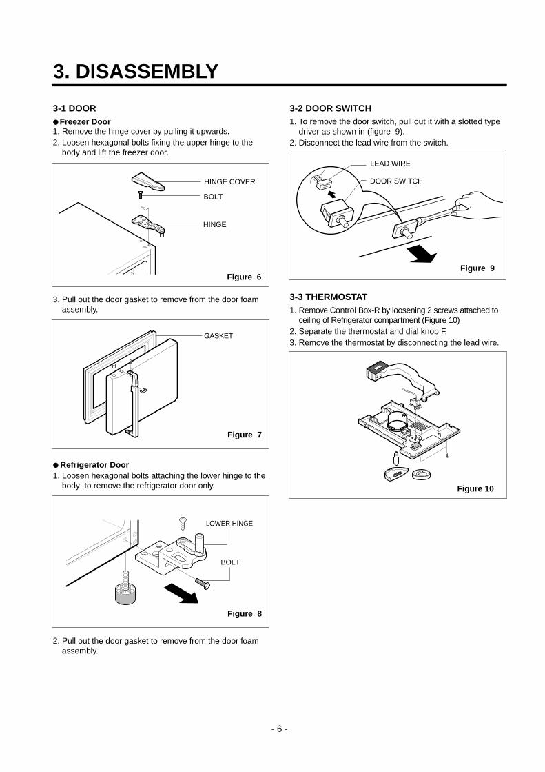
3-1 DOOR Freezer Door1. Remove the hinge cover by pulling it upwards. 2. Loosen hexagonal bolts fixing the upper hinge to the
body and lift the freezer door.
3. Pull out the door gasket to remove from the door foamassembly.
Refrigerator Door1. Loosen hexagonal bolts attaching the lower hinge to the
body to remove the refrigerator door only.
2. Pull out the door gasket to remove from the door foamassembly.
3-2 DOOR SWITCH1. To remove the door switch, pull out it with a slotted type
driver as shown in (figure 9).2. Disconnect the lead wire from the switch.
3-3 THERMOSTAT1. Remove Control Box-R by loosening 2 screws attached to
ceiling of Refrigerator compartment (Figure 10)2. Separate the thermostat and dial knob F.3. Remove the thermostat by disconnecting the lead wire.
3. DISASSEMBLY
- 6 -
BOLT
HINGE
HINGE COVER
Figure 6
GASKET
Figure 7
LOWER HINGE
BOLT
Figure 8
DOOR SWITCH
LEAD WIRE
Figure 9
Figure 10
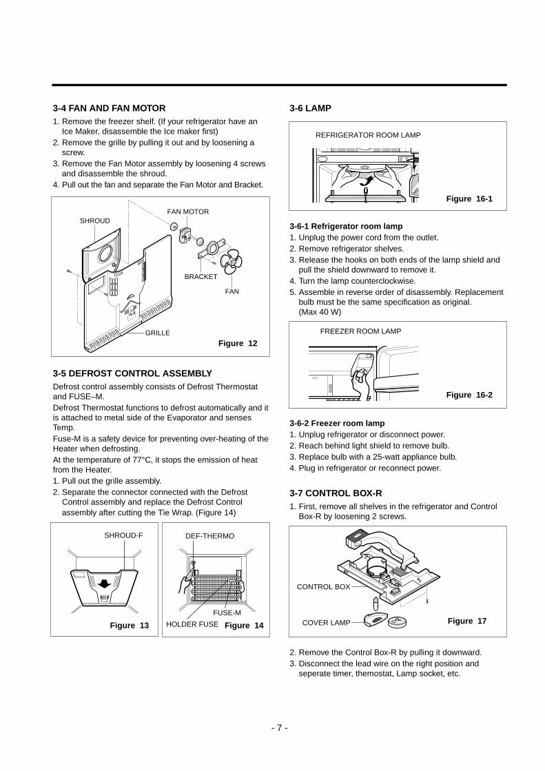
3-4 FAN AND FAN MOTOR1. Remove the freezer shelf. (If your refrigerator have an
Ice Maker, disassemble the Ice maker first)2. Remove the grille by pulling it out and by loosening a
screw.3. Remove the Fan Motor assembly by loosening 4 screws
and disassemble the shroud.4. Pull out the fan and separate the Fan Motor and Bracket.
3-5 DEFROST CONTROL ASSEMBLYDefrost control assembly consists of Defrost Thermostatand FUSE–M.Defrost Thermostat functions to defrost automatically and itis attached to metal side of the Evaporator and sensesTemp.Fuse-M is a safety device for preventing over-heating of theHeater when defrosting.At the temperature of 77°C, it stops the emission of heatfrom the Heater.1. Pull out the grille assembly.2. Separate the connector connected with the Defrost
Control assembly and replace the Defrost Controlassembly after cutting the Tie Wrap. (Figure 14)
3-6 LAMP
3-6-1 Refrigerator room lamp1. Unplug the power cord from the outlet.2. Remove refrigerator shelves.3. Release the hooks on both ends of the lamp shield and
pull the shield downward to remove it.4. Turn the lamp counterclockwise.5. Assemble in reverse order of disassembly. Replacement
bulb must be the same specification as original. (Max 40 W)
3-6-2 Freezer room lamp1. Unplug refrigerator or disconnect power.2. Reach behind light shield to remove bulb.3. Replace bulb with a 25-watt appliance bulb.4. Plug in refrigerator or reconnect power.
3-7 CONTROL BOX-R1. First, remove all shelves in the refrigerator and Control
Box-R by loosening 2 screws.
2. Remove the Control Box-R by pulling it downward.3. Disconnect the lead wire on the right position and
seperate timer, themostat, Lamp socket, etc.
- 7 -
FAN
BRACKET
SHROUD
GRILLE
FAN MOTOR
Figure 12
SHROUD-F
Figure 13
DEF-THERMO
FUSE-M
HOLDER FUSE Figure 14
REFRIGERATOR ROOM LAMP
FREEZER ROOM LAMP
Figure 16-1
Figure 16-2
CONTROL BOX
COVER LAMP Figure 17
4-1 COMPRESSOR4-1-1 Role
The compressor intakes low temperature and low pressuregas evaporated from evaporator of the refrigerator, andcondenses this gas to high temperature and high pressuregas, and then plays delivering role to condenser.
4-1-2 CompositionThe compressor includes overload protection. The PTCstarter and OLP (overload protector) are outside thecompressor. Since the compressor is manufactured totolerances of 1 micron, and is sealed in a dust - andmoisture - free environment, use extreme caution whenrepairing it.
4-1-3 Note for Usage(1) Be careful not to allow over-voltage and over-current.(2) No Strike
If applying forcible power or strike (dropping or carelesshandling), poor operation and noise may occur.
(3) Use proper electric components appropriate to theCompressor.
(4) Note to Keep Compressor.If Compressor gets wet in the rain and rust in the pin ofHermetic Terminal, the result may be poor operationand poor contact may cause.
(5) Be careful that dust, humidity, and welding flux don'tcontaminate the compressor inside when replacing theCompressor. Dust, humidity, and flux due to weldingwhich contaminates the cylinder may cause lockageand noise.
4-2 PTC-STARTER
4-2-1 Composition of PTC-Starter(1) PTC (Positive Temperature Coefficient) is a no-contact
semiconductor starting device which uses ceramicmaterial consisting of BaTiO3.
(2) The higher the temperature is, the higher the resistancevalue. These features are used as starting device forthe Motor.
4-2-2 Role of PTC-Starter(1) PTC is attached to Hermetic Compressor used for
Refrigerator, Show Case, and starting Motor.(2) Compressor for household refrigerator applies to
single-phase induction Motor.For normal operation of the single-phase inductionmotor, in the starting operation flows in both main coiland sub-coil. After the starting is over, the current insubcoil is cut off. The proper features of PTC play allthe above roles. So, PTC is used as a motor startingdevice.
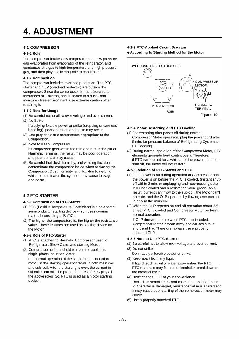
4-2-3 PTC-Applied Circuit Diagram According to Starting Method for the Motor
4-2-4 Motor Restarting and PTC Cooling(1) For restarting after power off during normal
Compressor Motor operation, plug the power cord after5 min. for pressure balance of Refrigerating Cycle andPTC cooling.
(2) During normal operation of the Compressor Motor, PTCelements generate heat continuously. Therefore, if PTC isn't cooled for a while after the power has beenshut off, the motor will not restart.
4-2-5 Relation of PTC-Starter and OLP(1) If the power is off during operation of Compressor and
the power is on before the PTC is cooled, (instant shut-off within 2 min. or unplugging and reconnecting), thePTC isn't cooled and a resistance value grows. As aresult, current can't flow to the sub-coil, the Motor can'toperate, and the OLP operates by flowing over currentin only in the main-coil.
(2) While the OLP repeats on and off operation about 3-5times, PTC is cooled and Compressor Motor performsnormal operation.If OLP doesn't operate when PTC is not cooled,Compressor Motor is worn away and causes circuit-short and fire. Therefore, always use a properlyattached OLP.
4-2-6 Note to Use PTC-Starter(1) Be careful not to allow over-voltage and over-current.(2) Do not strike
Don't apply a forcible power or strike.(3) Keep apart from any liquid.
If liquid, such as oil or water away enters the PTC, PTC materials may fail due to insulation breakdown ofthe material itself.
(4) Don't change PTC at your convenience.Don't disassemble PTC and case. If the exterior to thePTC-starter is damaged, resistance value is altered andit may cause poor starting of the compressor motor maycause.
(5) Use a properly attached PTC.
4. ADJUSTMENT
- 8 -
PTC STARTER HERMETICTERMINAL
COMPRESSORMOTOR
C
MS M
3 6
5
S
PTC
OVERLOAD PROTECTOR(O.L.P)
RSIRFigure 19
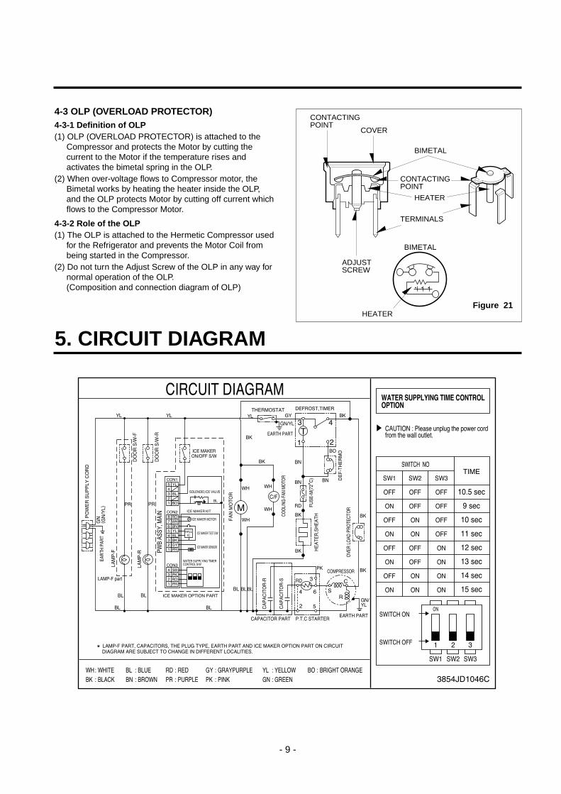
4-3 OLP (OVERLOAD PROTECTOR)4-3-1 Definition of OLP(1) OLP (OVERLOAD PROTECTOR) is attached to the
Compressor and protects the Motor by cutting thecurrent to the Motor if the temperature rises andactivates the bimetal spring in the OLP.
(2) When over-voltage flows to Compressor motor, theBimetal works by heating the heater inside the OLP, and the OLP protects Motor by cutting off current whichflows to the Compressor Motor.
4-3-2 Role of the OLP(1) The OLP is attached to the Hermetic Compressor used
for the Refrigerator and prevents the Motor Coil frombeing started in the Compressor.
(2) Do not turn the Adjust Screw of the OLP in any way fornormal operation of the OLP.(Composition and connection diagram of OLP)
- 9 -
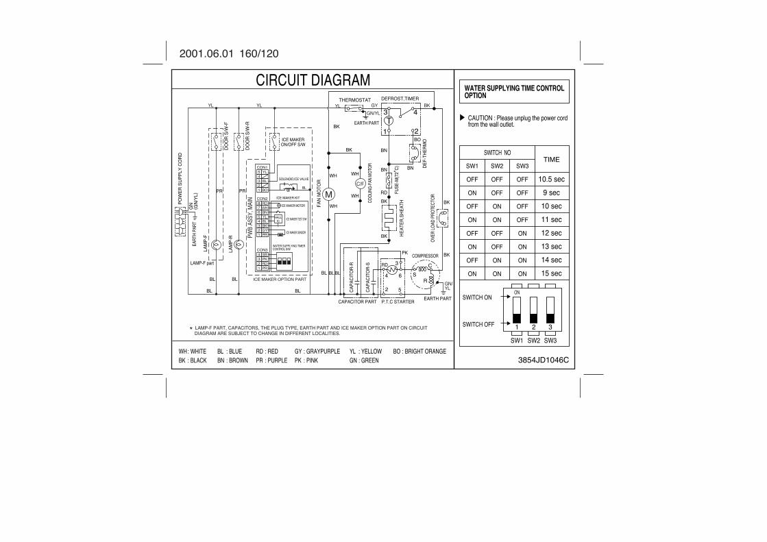
5. CIRCUIT DIAGRAM
CONTACTINGPOINT
COVER
BIMETAL
CONTACTINGPOINT
HEATER
TERMINALS
ADJUSTSCREW
HEATER
BIMETAL
Figure 21
6. TROUBLESHOOTING
- 10 -
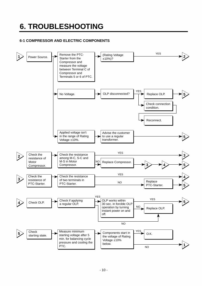
6-1 COMPRESSOR AND ELECTRIC COMPONENTS
1
2
3
4
5
2
5
5
3
5
4
5
5
1
43
YES
YES
YES
YES
NO
NO
YESYES
YES
NO
NO
NO
Power Source.
No Voltage.
(Rating Voltage±10%)?
Replace OLP.
Reconnect.
ReplacePTC-Starter.
Replace OLP.
O.K.
Check connectioncondition.
OLP disconnected?
Advise the customerto use a regulartransformer.
Replace Compressor.
OLP works within30 sec. in forcible OLPoperation by turninginstant power on andoff.
Components start inthe voltage of RatingVoltage ±10%below.
Applied voltage isn'tin the range of RatingVoltage ±10%.
Remove the PTC-Starter from theCompressor andmeasure the voltagebetween Terminal C ofCompressor andTerminals 5 or 6 of PTC.
Check the resistanceamong M-C, S-C andM-S in MotorCompressor.
Check the resistanceof two terminals inPTC-Starter.
Check if applyinga regular OLP.
Measure minimumstarting voltage after 5min. for balancing cyclepressure and cooling thePTC.
Check theresistance ofMotorCompressor.
Check theresistance ofPTC-Starter.
Check OLP.
Checkstarting state.
- 11 -
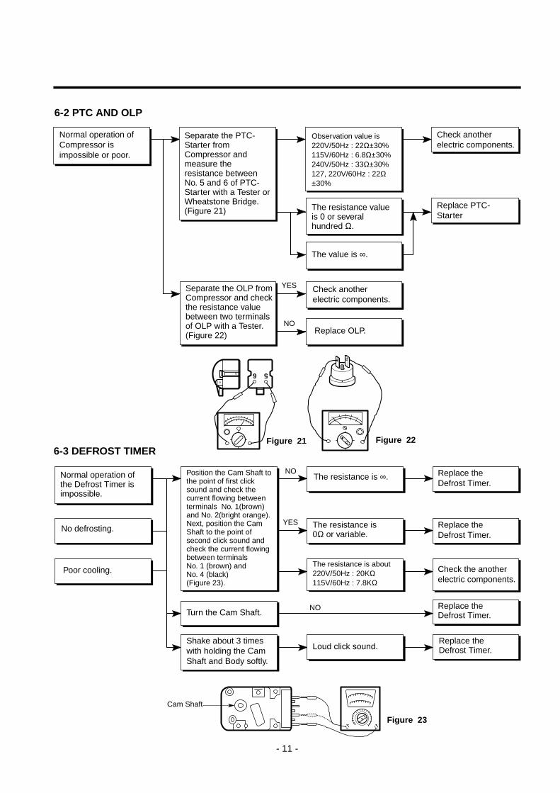
6-2 PTC AND OLP
6 5
YES
NO
NO
YES
NO
Cam Shaft
Normal operation ofCompressor isimpossible or poor.
Separate the PTC-Starter fromCompressor andmeasure theresistance betweenNo. 5 and 6 of PTC-Starter with a Tester orWheatstone Bridge.(Figure 21)
Separate the OLP fromCompressor and checkthe resistance valuebetween two terminalsof OLP with a Tester.(Figure 22)
Observation value is220V/50Hz : 22Ω±30%115V/60Hz : 6.8Ω±30%240V/50Hz : 33Ω±30%127, 220V/60Hz : 22Ω±30%
The resistance valueis 0 or severalhundred Ω.
The value is ∞.
Check anotherelectric components.
Replace OLP.
Check anotherelectric components.
Replace PTC-Starter
Figure 21 Figure 22
Figure 23
Normal operation ofthe Defrost Timer isimpossible.
No defrosting.
Poor cooling.
Position the Cam Shaft tothe point of first clicksound and check thecurrent flowing betweenterminals No. 1(brown)and No. 2(bright orange).Next, position the CamShaft to the point ofsecond click sound andcheck the current flowingbetween terminalsNo. 1 (brown) andNo. 4 (black)(Figure 23).
Turn the Cam Shaft.
Shake about 3 timeswith holding the CamShaft and Body softly.
The resistance is ∞.
The resistance is0Ω or variable.
The resistance is about220V/50Hz : 20KΩ115V/60Hz : 7.8KΩ
Loud click sound.
Replace theDefrost Timer.
Replace theDefrost Timer.
Replace theDefrost Timer.
Check the anotherelectric components.
Replace theDefrost Timer.
6-3 DEFROST TIMER
- 12 -
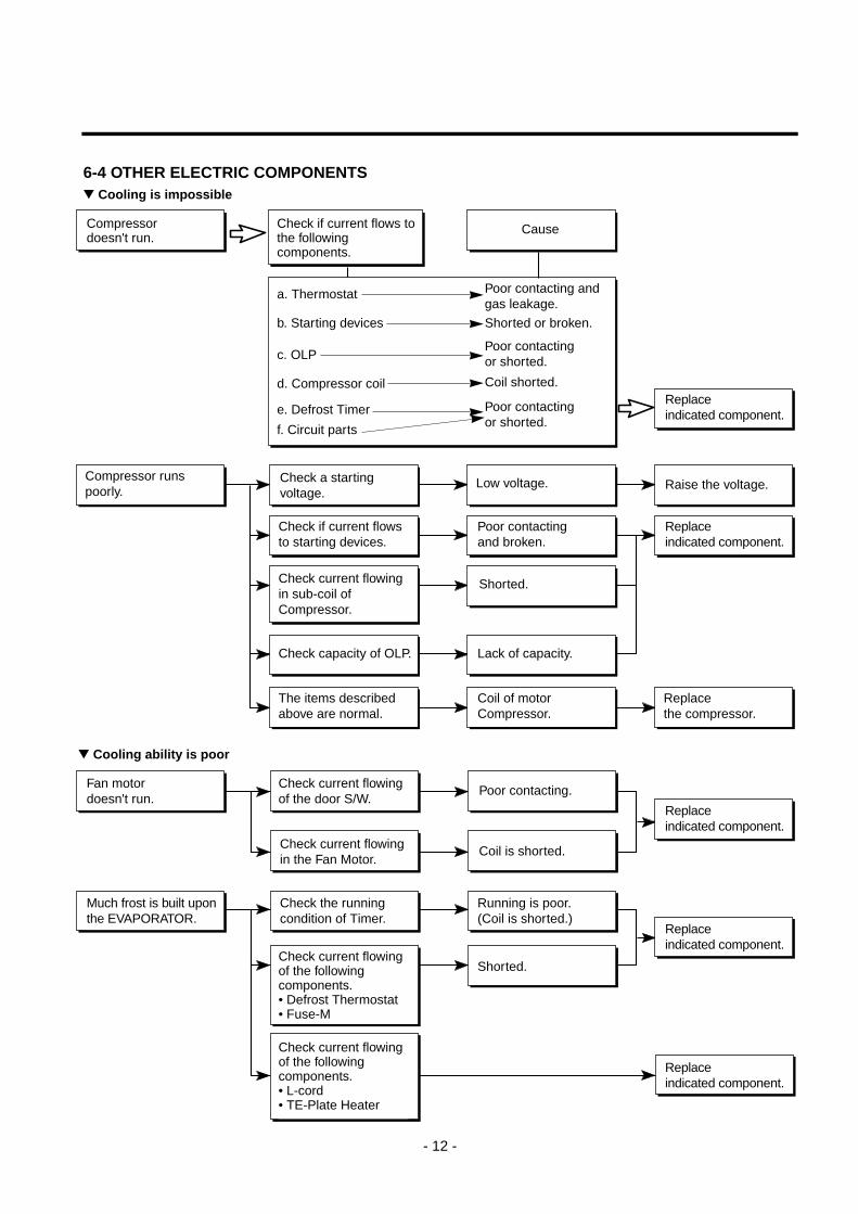
Cooling is impossible
Compressordoesn't run.
Compressor runspoorly.
Check a startingvoltage.
Check if current flows tothe followingcomponents.
a. Thermostat
b. Starting devices
c. OLP
d. Compressor coil
e. Defrost Timer
f. Circuit parts
Low voltage.
Poor contacting andgas leakage.
Shorted or broken.
Poor contactingor shorted.
Coil shorted.
Poor contactingor shorted.
Poor contactingand broken.
Shorted.
Lack of capacity.
Coil of motorCompressor.
Replacethe compressor.
Replaceindicated component.
Raise the voltage.
Replaceindicated component.
Cause
Check if current flowsto starting devices.
Check current flowingin sub-coil ofCompressor.
Check capacity of OLP.
The items describedabove are normal.
Cooling ability is poor
Fan motordoesn't run.
Much frost is built uponthe EVAPORATOR.
Poor contacting.
Coil is shorted.
Shorted.
Replaceindicated component.
Replaceindicated component.
Replaceindicated component.
Running is poor.(Coil is shorted.)
Check current flowingof the door S/W.
Check current flowingin the Fan Motor.
Check the runningcondition of Timer.
Check current flowingof the followingcomponents.• Defrost Thermostat• Fuse-M
Check current flowingof the followingcomponents.• L-cord• TE-Plate Heater
6-4 OTHER ELECTRIC COMPONENTS
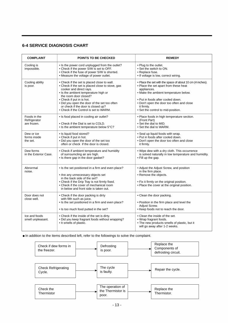
6-4 SERVICE DIAGNOSIS CHART
- 13 -
COMPLAINT POINTS TO BE CHECKED REMEDY
Cooling is • Is the power cord unplugged from the outlet? • Plug to the outlet.impossible. • Check if the power S/W is set to OFF. • Set the switch to ON.
• Check if the fuse of power S/W is shorted. • Replace fuse.• Measure the voltage of power outlet. • If voltage is low, correct wiring.
Cooling ability • Check if the set is placed close to wall. • Place the set with the space of about 10 cm (4 inches).is poor. • Check if the set is placed close to stove, gas • Place the set apart from these heat
• cooker and direct rays. • appliances.• Is the ambient temperature high or • Make the ambient temperature below.• the room door closed?• Check if put in is hot. • Put in foods after cooled down.• Did you open the door of the set too often • Don't open the door too often and close• or check if the door is closed up? • it firmly.• Check if the Control is set to WARM. • Set the control to mid-position.
Foods in the • Is food placed in cooling air outlet? • Place foods in high temperature section.Refrigerator • (Front Part)are frozen. • Check if the Dial is set to COLD. • Set the dial to MID.
• Is the ambient temperature below 5°C? • Set the dial to WARM.
Dew or ice • Is liquid food stored? • Seal up liquid foods with wrap.forms inside • Check if put in hot. • Put in foods after cooled down.the set. • Did you open the door of the set too • Don't open the door too often and close
• often or check if the door is closed. • it firmly.
Dew forms • Check if ambient temperature and humidity • Wipe dew with a dry cloth. This occurrencein the Exterior Case. of surroumcling air are high. • is solved naturally in low temperature and humidity.
• Is there gap in the door gasket? • Fill up the gap.
Abnormal • Is the set positioned in a firm and even place? • Adjust the Adjust Screw, and positionnoise. • in the firm place.
• Are any unnecessary objects set • Remove the objects.• in the back side of the set?• Check if the Drip Tray is not firmly fixed. • Fix it firmly on the original position.• Check if the cover of mechanical room • Place the cover at the original position.• in below and front side is taken out.
Door does not • Check if the door packing is dirty • Clean the door packing.close well. • with filth such as juice.
• Is the set positioned in a firm and even place? • Position in the firm place and level the• Adjust Screw.
• Is too much food putted in the set? • Keep foods not to reach the door.
Ice and foods • Check if the inside of the set is dirty. • Clean the inside of the set.smell unpleasant. • Did you keep fragrant foods without wrapping? • Wrap fragrant foods.
• It smells of plastic. • The new products smells of plastic, but it • will go away after 1-2 weeks.
In addition to the items described left, refer to the followings to solve the complaint.
Check if dew forms inthe freezer.
Replace theComponents ofdefrosting circuit.
Check RefrigeratingCycle.
Check the Thermistor
Defrostingis poor.
The cycleis faulty.
Repair the cycle.
Replace theThermistor.
The operation ofthe Thermistor ispoor.
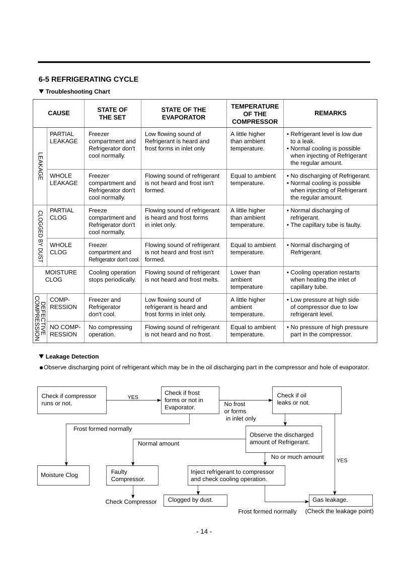
6-5 REFRIGERATING CYCLE
- 14 -
Troubleshooting Chart
Leakage Detection
Observe discharging point of refrigerant which may be in the oil discharging part in the compressor and hole of evaporator.
YES
YES
Check if compressorruns or not.
Check if frostforms or not inEvaporator.
Observe the dischargedamount of Refrigerant.
Inject refrigerant to compressorand check cooling operation.
Clogged by dust. Gas leakage.
FaultyCompressor.
Moisture Clog
Check if oilleaks or not.
Frost formed normally
Normal amount
No or much amount
(Check the leakage point)Frost formed normally
No frostor formsin inlet only
Check Compressor
PARTIAL Freezer Low flowing sound of A little higher • Refrigerant level is low due LEAKAGE compartment and Refrigerant is heard and than ambient • to a leak.
Refrigerator don't frost forms in inlet only temperature. • Normal cooling is possiblecool normally. • when injecting of Refrigerant
• the regular amount.
WHOLE Freezer Flowing sound of refrigerant Equal to ambient • No discharging of Refrigerant.LEAKAGE compartment and is not heard and frost isn't temperature. • Normal cooling is possible
Refrigerator don't formed. • when injecting of Refrigerantcool normally. • the regular amount.
PARTIAL Freeze Flowing sound of refrigerant A little higher • Normal discharging ofCLOG compartment and is heard and frost forms than ambient • refrigerant.
Refrigerator don't in inlet only. temperature. • The capillary tube is faulty.cool normally.
WHOLE Freezer Flowing sound of refrigerant Equal to ambient • Normal discharging ofCLOG compartment and is not heard and frost isn't temperature. • Refrigerant.
Refrigerator don't cool. formed.
MOISTURE Cooling operation Flowing sound of refrigerant Lower than • Cooling operation restartsCLOG stops periodically. is not heard and frost melts. ambient • when heating the inlet of
temperature • capillary tube.
COMP- Freezer and Low flowing sound of A little higher • Low pressure at high side RESSION Refrigerator refrigerant is heard and ambient • of compressor due to low
don't cool. frost forms in inlet only. temperature. • refrigerant level.
NO COMP- No compressing Flowing sound of refrigerant Equal to ambient • No pressure of high pressureRESSION operation. is not heard and no frost. temperature. • part in the compressor.
CAUSETEMPERATURE
OF THECOMPRESSOR
REMARKSSTATE OFTHE SET
STATE OF THEEVAPORATOR
LEA
KA
GE
CLO
GG
ED
BY
DU
ST
DE
FE
CT
IVE
CO
MP
RE
SS
ION
- 15 -
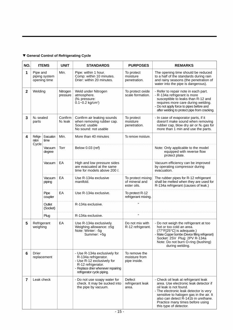
NO. ITEMS UNIT STANDARDS PURPOSES REMARKS
General Control of Refrigerating Cycle
Pipe andpiping systemopening time
Welding
N2 sealedparts
Refrige-rationCycle
Refrigerantweighing
Drierreplacement
Leak check
1
2
3
4
5
6
7
Min.
Nitrogenpressure
ConfirmN2 leak
Min.
Torr
EA
EA
EA
EA
Pipe: within 1 hour.Comp: within 10 minutes.Drier: within 20 minutes.
Weld under Nitrogenatmosphere. (N2 pressure: 0.1~0.2 kg/cm2)
Confirm air leaking soundswhen removing rubber cap.Sound: usableNo sound: not usable
More than 40 minutes
Below 0.03 (ref)
High and low pressure sidesare evacuated at the sametime for models above 200 l.
Use R-134a exclusivemanifold.
Use R-134a exclusive.
R-134a exclusive.
R-134a exclusive.
Use R-134a exclusively.Weighing allowance: ±5gNote: Winter: -5g
Summer: +5g
- Use R-134a exclusively forR-134a refrigerator.
- Use R-12 exclusively for R-12 refrigerator.
- Replace drier whenever repairingrefrigerator cycle piping.
- Do not use soapy water forcheck. It may be sucked intothe pipe by vacuum.
To protectmoisturepenetration.
To protect oxidescale formation.
To protectmoisturepenetration.
To remove moisture.
To protect mixingof mineral andester oils.
To protect R-12refrigerant mixing.
"
"
Do not mix withR-12 refrigerant.
To remove themoisture frompipe inside.
Defectrefrigerant leakarea.
The opening time should be reducedto a half of the standards during rainand rainy seasons (the penetration ofwater into the pipe is dangerous).
- Refer to repair note in each part.- R-134a refrigerant is more
susceptible to leaks than R-12 andrequires more care during welding.
- Do not apply force to pipes before andafter welding to protect pipe from cracking.
- In case of evaporator parts, if itdoesn't make sound when removingrubber cap, blow dry air or N2 gas formore than 1 min and use the parts.
Note: Only applicable to the modelequipped with reverse flowprotect plate.
Vacuum efficiency can be improvedby operating compressor duringevacuation.
The rubber pipes for R-12 refrigerantshall be melted when they are used forR-134a refrigerant (causes of leak.)
- Do not weigh the refrigerant at toohot or too cold an area.(77°F[25°C] is adequate.)
- Make Copper bombe (Device filling refrigerant)Socket: 2SV Plug: 2PV R-134aNote: Do not burn O-ring (bushing)
during welding.
- Check oil leak at refrigerant leakarea. Use electronic leak detector ifoil leak is not found.
- The electronic leak detector is verysensitive to halogen gas in the air. Italso can detect R-141b in urethane.Practice many times before usingthis type of detector.
Evacuationtime
Vacuumdegree
Vacuum
Vacuumpiping
Pipecoupler
Outlet(Socket)
Plug
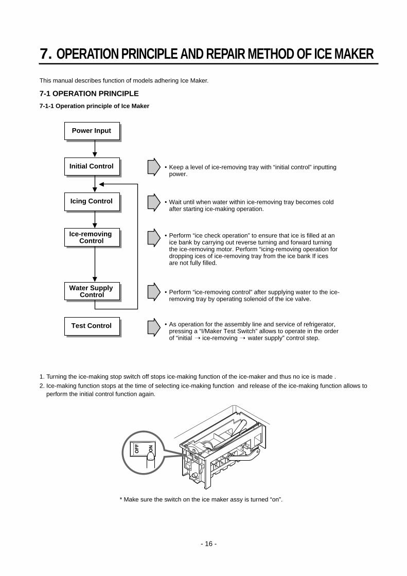
This manual describes function of models adhering Ice Maker.
7-1 OPERATION PRINCIPLE
7-1-1 Operation principle of Ice Maker
1. Turning the ice-making stop switch off stops ice-making function of the ice-maker and thus no ice is made .
2. Ice-making function stops at the time of selecting ice-making function and release of the ice-making function allows toperform the initial control function again.
7. OPERATION PRINCIPLE AND REPAIR METHOD OF ICE MAKER
- 16 -
•
Power Input
Initial Control
Icing Control
Ice-removing Control
Water Supply Control
Test Control
Keep a level of ice-removing tray with “initial control” inputting power.
• Wait until when water within ice-removing tray becomes cold after starting ice-making operation.
• Perform “ice-removing control” after supplying water to the ice-removing tray by operating solenoid of the ice valve.
• As operation for the assembly line and service of refrigerator, pressing a “I/Maker Test Switch” allows to operate in the order of “initial ice-removing water supply” control step.
• Perform “ice check operation” to ensure that ice is filled at an ice bank by carrying out reverse turning and forward turning the ice-removing motor. Perform “icing-removing operation for dropping ices of ice-removing tray from the ice bank If ices are not fully filled.
* Make sure the switch on the ice maker assy is turned “on”.
7-2 Function of Ice maker7-2-1 Initial control function
1. The level of the ice-removing tray (ice-removing container) after completing the MICOM initialization in the initial POWERON,returning to electricity failure and turning-off of ice-making stop switches. Namely, detection lever operates up and down.
2. The level of ice-removing container is detected with high / low output signal of hall sensor. In another words, operation is performed in order to keep a level by operating ice-removing motor so that high or low volt-age could be applied in the MICOM PIN.
3. No signal change of hall sensors until a minute after operating the ice-removing motor should be considered as failure. Inthis case, stop the automatic ice-remover and then reset the ice-maker initialization if considered as normal after perform-ing continuous check in a cycle of an hour.
4. Keeping of the ice-removing tray (ice-removing container) should be considered initial control is completed.
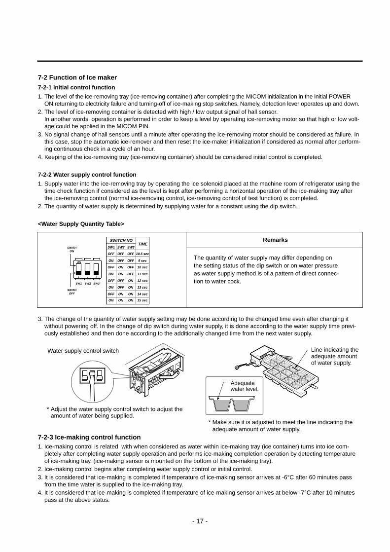
7-2-2 Water supply control function
1. Supply water into the ice-removing tray by operating the ice solenoid placed at the machine room of refrigerator using thetime check function if considered as the level is kept after performing a horizontal operation of the ice-making tray afterthe ice-removing control (normal ice-removing control, ice-removing control of test function) is completed.
2. The quantity of water supply is determined by supplying water for a constant using the dip switch.
<Water Supply Quantity Table>
3. The change of the quantity of water supply setting may be done according to the changed time even after changing itwithout powering off. In the change of dip switch during water supply, it is done according to the water supply time previ-ously established and then done according to the additionally changed time from the next water supply.
7-2-3 Ice-making control function1. Ice-making control is related with when considered as water within ice-making tray (ice container) turns into ice com-
pletely after completing water supply operation and performs ice-making completion operation by detecting temperatureof ice-making tray. (ice-making sensor is mounted on the bottom of the ice-making tray).
2. Ice-making control begins after completing water supply control or initial control.3. It is considered that ice-making is completed if temperature of ice-making sensor arrives at -6°C after 60 minutes pass
from the time water is supplied to the ice-making tray.4. It is considered that ice-making is completed if temperature of ice-making sensor arrives at below -7°C after 10 minutes
pass at the above status.
- 17 -
ON
SWITHON
SWITHOFF
1 2 3
SW1
SWITCH NOTIME
SW1
OFF OFF OFF
OFF OFF ON
ON OFF OFF
ON ON OFF
OFF ON ON
ON OFF ON
ON ON ON
OFF ON OFF
10.5 sec
12 sec
9 sec
11 sec
14 sec
13 sec
15 sec
10 sec
SW2 SW3
SW2 SW3
Remarks
The quantity of water supply may differ depending onthe setting status of the dip switch or on water pressureas water supply method is of a pattern of direct connec-tion to water cock.
* Make sure it is adjusted to meet the line indicating theadequate amount of water supply.
Line indicating theadequate amountof water supply.
Adequate water level.
Water supply control switch
* Adjust the water supply control switch to adjust theamount of water being supplied.
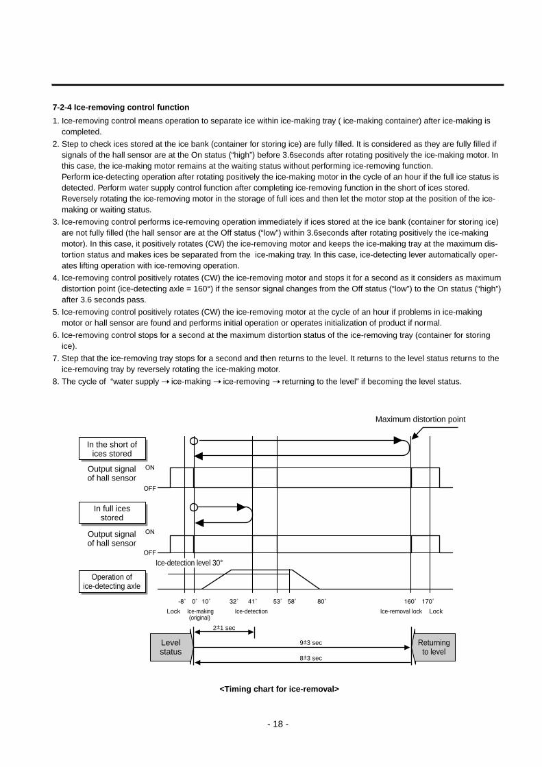
7-2-4 Ice-removing control function
1. Ice-removing control means operation to separate ice within ice-making tray ( ice-making container) after ice-making iscompleted.
2. Step to check ices stored at the ice bank (container for storing ice) are fully filled. It is considered as they are fully filled ifsignals of the hall sensor are at the On status (“high”) before 3.6seconds after rotating positively the ice-making motor. Inthis case, the ice-making motor remains at the waiting status without performing ice-removing function. Perform ice-detecting operation after rotating positively the ice-making motor in the cycle of an hour if the full ice status isdetected. Perform water supply control function after completing ice-removing function in the short of ices stored.Reversely rotating the ice-removing motor in the storage of full ices and then let the motor stop at the position of the ice-making or waiting status.
3. Ice-removing control performs ice-removing operation immediately if ices stored at the ice bank (container for storing ice)are not fully filled (the hall sensor are at the Off status (“low”) within 3.6seconds after rotating positively the ice-makingmotor). In this case, it positively rotates (CW) the ice-removing motor and keeps the ice-making tray at the maximum dis-tortion status and makes ices be separated from the ice-making tray. In this case, ice-detecting lever automatically oper-ates lifting operation with ice-removing operation.
4. Ice-removing control positively rotates (CW) the ice-removing motor and stops it for a second as it considers as maximumdistortion point (ice-detecting axle = 160°) if the sensor signal changes from the Off status (“low”) to the On status (“high”)after 3.6 seconds pass.
5. Ice-removing control positively rotates (CW) the ice-removing motor at the cycle of an hour if problems in ice-makingmotor or hall sensor are found and performs initial operation or operates initialization of product if normal.
6. Ice-removing control stops for a second at the maximum distortion status of the ice-removing tray (container for storingice).
7. Step that the ice-removing tray stops for a second and then returns to the level. It returns to the level status returns to theice-removing tray by reversely rotating the ice-making motor.
8. The cycle of “water supply ice-making ice-removing returning to the level” if becoming the level status.
- 18 -
In the short ofices stored
Output signalof hall sensor
In full icesstored
Output signalof hall sensor
Operation ofice-detecting axle
Ice-detection level 30°
Maximum distortion point
Ice-making(original)
Lock
2±1 sec
9±3 sec
8±3 sec
Ice-detection Ice-removal lock Lock
Levelstatus
Returningto level
<Timing chart for ice-removal>
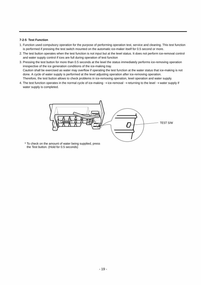
7-2-5 Test Function
1. Function used compulsory operation for the purpose of performing operation test, service and cleaning. This test functionis performed if pressing the test switch mounted on the automatic ice-maker itself for 0.5 second or more.
2. The test button operates when the test function is not input but at the level status. It does not perform ice-removal controland water supply control if ices are full during operation of test function
3. Pressing the test button for more than 0.5 seconds at the level the status immediately performs ice-removing operationirrespective of the ice generation conditions of the ice-making tray. Caution shall be exercised as water may overflow if operating the test function at the water status that ice-making is notdone. A cycle of water supply is performed at the level adjusting operation after ice-removing operation. Therefore, the test button allows to check problems in ice-removing operation, level operation and water supply.
4. The test function operates in the normal cycle of ice-making ice-removal returning to the level water supply ifwater supply is completed.
- 19 -
TEST S/W
* To check on the amount of water being supplied, pressthe Test button. (Hold for 0.5 seconds)
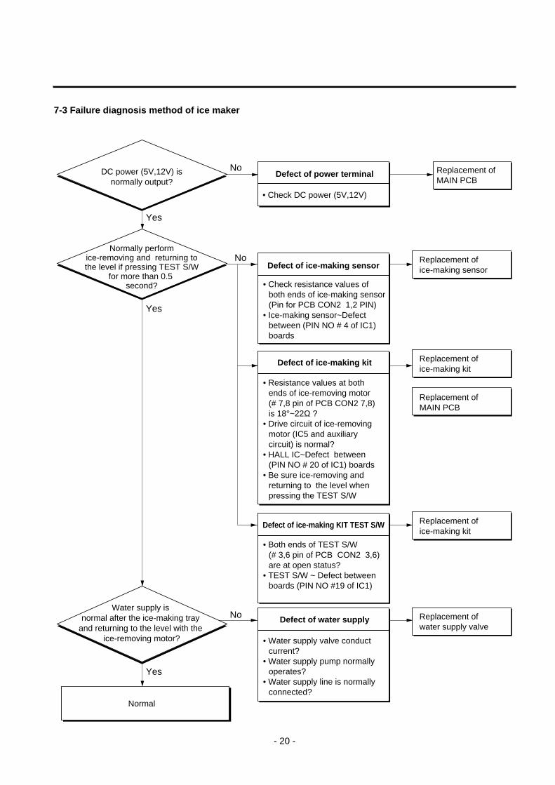
7-3 Failure diagnosis method of ice maker
- 20 -
No
Yes
No
No
Yes
Yes
DC power (5V,12V) isnormally output?
Defect of power terminal
• Check DC power (5V,12V)
Replacement of MAIN PCB
Normally performice-removing and returning tothe level if pressing TEST S/W
for more than 0.5 second?
Defect of ice-making sensor Replacement of ice-making sensor
Defect of ice-making kit Replacement of ice-making kit
Replacement of MAIN PCB
Defect of ice-making KIT TEST S/W Replacement of ice-making kit
Replacement of water supply valve
Defect of water supplyWater supply is
normal after the ice-making tray and returning to the level with the
ice-removing motor?
Normal
• Check resistance values of both ends of ice-making sensor(Pin for PCB CON2 1,2 PIN)
• Ice-making sensor~Defect between (PIN NO # 4 of IC1) boards
• Both ends of TEST S/W (# 3,6 pin of PCB CON2 3,6) are at open status?
• TEST S/W ~ Defect between boards (PIN NO #19 of IC1)
• Water supply valve conduct current?
• Water supply pump normally operates?
• Water supply line is normally connected?
• Resistance values at both ends of ice-removing motor (# 7,8 pin of PCB CON2 7,8) is 18°~22Ω ?
• Drive circuit of ice-removing motor (IC5 and auxiliary circuit) is normal?
• HALL IC~Defect between (PIN NO # 20 of IC1) boards
• Be sure ice-removing and returning to the level when pressing the TEST S/W
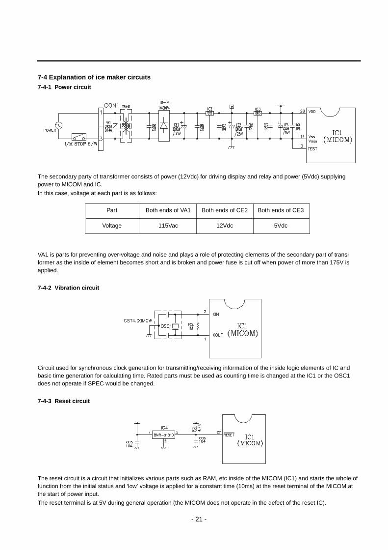
7-4 Explanation of ice maker circuits7-4-1 Power circuit
The secondary party of transformer consists of power (12Vdc) for driving display and relay and power (5Vdc) supplyingpower to MICOM and IC.
In this case, voltage at each part is as follows:
VA1 is parts for preventing over-voltage and noise and plays a role of protecting elements of the secondary part of trans-former as the inside of element becomes short and is broken and power fuse is cut off when power of more than 175V isapplied.
7-4-2 Vibration circuit
Circuit used for synchronous clock generation for transmitting/receiving information of the inside logic elements of IC andbasic time generation for calculating time. Rated parts must be used as counting time is changed at the IC1 or the OSC1does not operate if SPEC would be changed.
7-4-3 Reset circuit
The reset circuit is a circuit that initializes various parts such as RAM, etc inside of the MICOM (IC1) and starts the whole offunction from the initial status and ‘low’ voltage is applied for a constant time (10ms) at the reset terminal of the MICOM atthe start of power input.
The reset terminal is at 5V during general operation (the MICOM does not operate in the defect of the reset IC).
- 21 -
Part Both ends of VA1 Both ends of CE2 Both ends of CE3
Voltage 115Vac 12Vdc 5Vdc
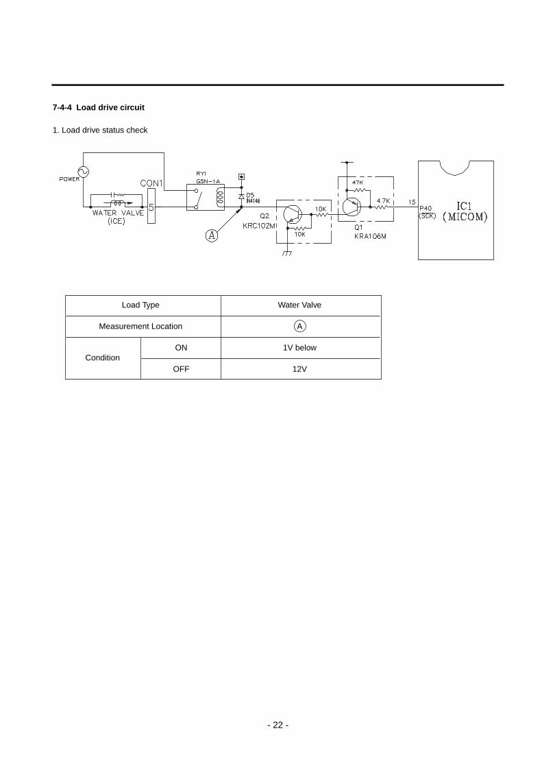
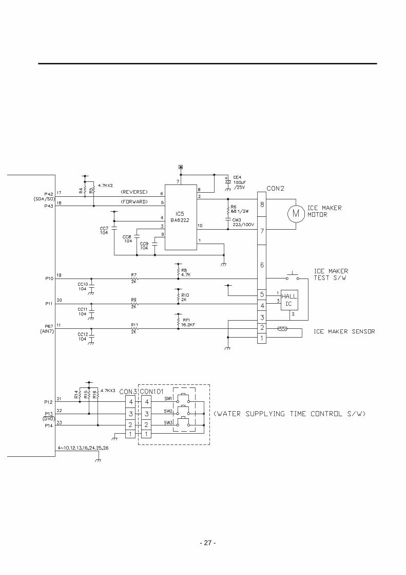
7-4-4 Load drive circuit
1. Load drive status check
- 22 -
Load Type Water Valve
Measurement Location A
ConditionON 1V below
OFF 12V
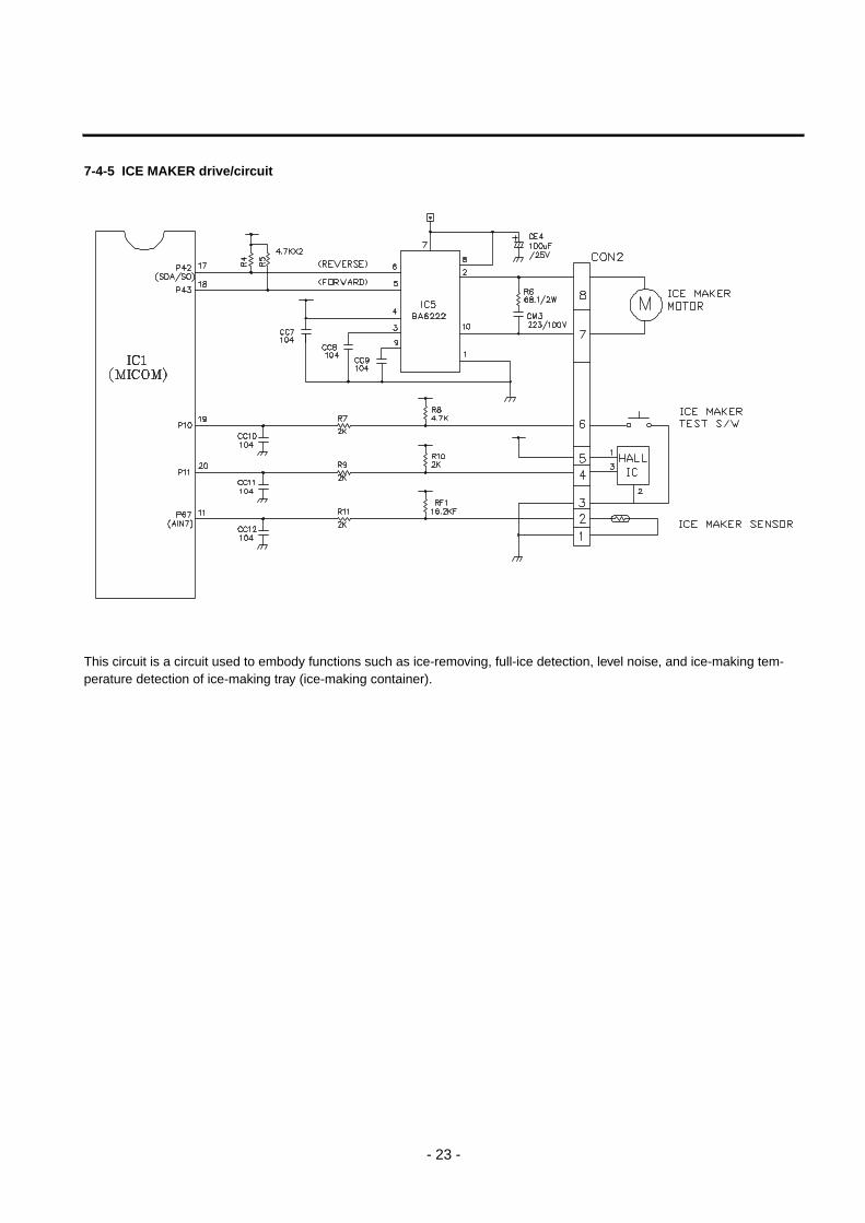
7-4-5 ICE MAKER drive/circuit
This circuit is a circuit used to embody functions such as ice-removing, full-ice detection, level noise, and ice-making tem-perature detection of ice-making tray (ice-making container).
- 23 -
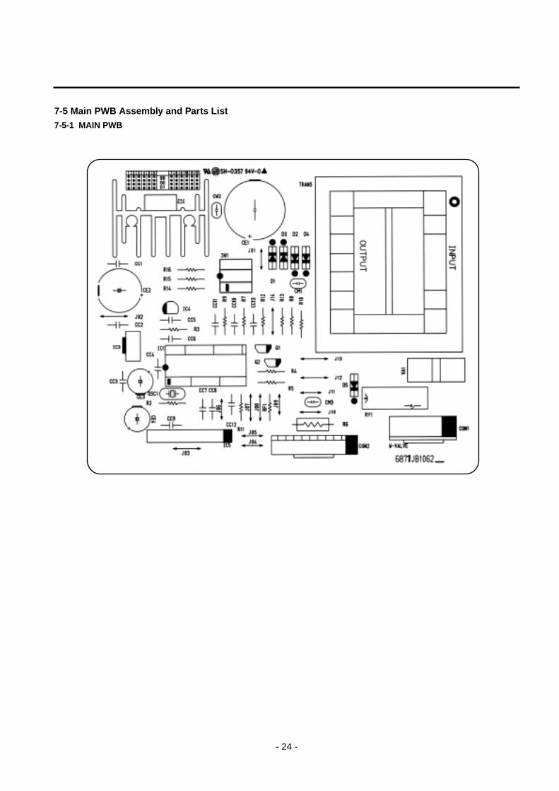
7-5 Main PWB Assembly and Parts List7-5-1 MAIN PWB
- 24 -
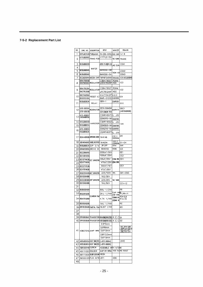
7-5-2 Replacement Part List
- 25 -
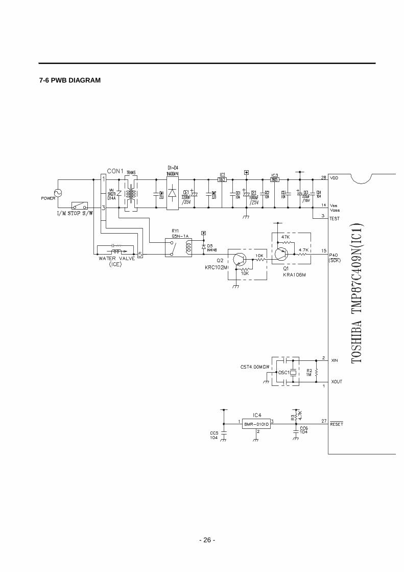
7-6 PWB DIAGRAM
- 26 -
- 27 -
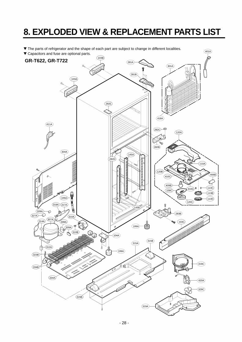
8. EXPLODED VIEW & REPLACEMENT PARTS LIST
- 28 -
The parts of refrigerator and the shape of each part are subject to change in different localities. Capacitors and fuse are optional parts.
GR-T622, GR-T722
106A
104A
106A
401A
304A
103C
309A
318A
308A314A307A
312A
317A
310B
310A
103A
105A
301A
283B
282B
406B
103B
411A
327A
328A
334B
323B
334A
315B
315A315B
319A
329C
420A
319C
113D
113B
113C410G
110A
410C
120B
409B
120C
158C
120A
145B
145A
282H
282E
282C
418A
281A
281B
- 29 -
154A
151B
151C
151D
151A
170A
147C
147A
151C
151D
141B
141C
170A
141A
140B
140C 140A
149A
330B405C
404A
329A
405A
332A
110C
3391AT
408A
409A
406A
158B
- 30 -
241C
241A
241D
241C
241C
241B
205A
205A
235A
243A
210A
233A
230A
203A
200A
201A
231A
244A
281E
212C
212A
212G
244E
212C
281E
244B
- 31 -
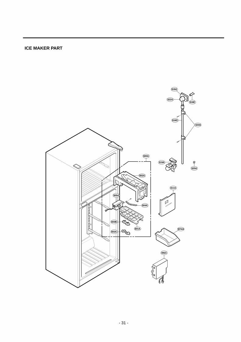
ICE MAKER PART
616E
623A
622A
618A
616D
620A
619A
605A
600A
603A
604A
5074AA
6923
601A
602A
603B
611A