Embed Size (px)
Citation preview

Hydraulics 3 Rapidly-Varied Flow - 1 Dr David Apsley
2. RAPIDLY-VARIED FLOW (RVF) AUTUMN 2018
Rapidly-varied flow is a significant change in water depth over a short distance (a few times
water depth). It occurs where there is a local disturbance to the balance between gravity and
friction (e.g. at a weir, venturi, sluice, free overfall, sudden change in slope) or a mismatch
between the depths imposed by upstream and downstream controls (hydraulic jump).
Often there is a flow transition between deep, slow flow (subcritical; Fr < 1) and shallow, fast
flow (supercritical; Fr > 1).
The assumption that the flow varies rapidly over a relatively short distance means that bed
friction is unimportant. Thus, for a smooth transition (e.g. weir, venturi or sluice), the total
head is usually assumed constant through this short region. For an abrupt transition (hydraulic
jump) there may be significant head loss, but it is associated with high levels of turbulence,
not bed friction.
Note that the hydrostatic pressure assumption can only be applied where near-parallel flow
has been established, either side of the rapidly-varying-flow region.
2.1 Hydraulic Jump
A hydraulic jump is an abrupt change from a shallow, high-speed flow to a deep, low-speed
flow of lower energy.
It occurs when a depth difference is imposed by upstream and downstream conditions. Rapid,
shallow flow may be created by, for example, a steep spillway or sluice. A slower and deeper
downstream flow may be controlled by a downstream weir or by a reduction in slope.
The triggering of a hydraulic jump at the base of a spillway is desirable to remove surplus
kinetic energy, in order to reduce downstream erosion.
Across a hydraulic jump:
mass is conserved;
the momentum principle is satisfied;
mechanical energy is lost (mostly as heat).
Assume, for simplicity:
velocity uniform over upstream and downstream cross-sections;
small slope (so that the downslope component of weight can be neglected);
the length of the jump is short (so that bed friction can be neglected);
wide or rectangular cross-section (but see the Examples for an alternative).
V1
A2
A1
V2

Hydraulics 3 Rapidly-Varied Flow - 2 Dr David Apsley
Continuity
The volume flow rate is the same at each section. Velocities can thus be related to
cross-sectional area A (and hence to depth) by
(1)
Momentum:
Consider a control volume encompassing the jump. By the momentum principle:
net pressure force = rate of change of momentum
Since streamlines are parallel there, pressures at inflow and outflow stations 1 and 2 are
hydrostatic and the average pressure is the pressure at the centroid; i.e. , where is
the depth of the centroid below the surface. Using this, and substituting for velocity,
(2)
At this point we restrict ourselves to a rectangular or wide channel (but, for different shapes,
see the Examples). With b the width of channel (or b = 1 unit for a “wide” channel):
, ,
and the momentum principle reduces to
Dividing by ρb:
Divide through by (non-zero by assumption) and then multiply by h1h2:
(3)
Since we are looking for the depth ratio , divide through by :
Since q = Vh, the RHS is or
. Hence,
(4)
(5)
V1
h2
h1
V2

Hydraulics 3 Rapidly-Varied Flow - 3 Dr David Apsley
This is a quadratic equation for the depth ratio and its positive root gives the
downstream depth in terms of upstream quantities:
(6)
Notes.
(1) Indices 1 and 2 can be exchanged to write the upstream depth in terms of downstream
quantities:
(7)
Thus, the depth formula, being dependent only on mass and momentum, doesn’t care
which of 1 and 2 refers to upstream or downstream conditions.
(2) The head loss in the jump is
Substituting for from (3), then (after a lot of algebra, omitted here):
(8)
Hence, for mechanical energy to be lost in the jump (H1 bigger than H2) we require
h2 > h1; i.e., on energy grounds, a hydraulic jump will always go from shallow to deep
in the direction of flow.
(3) Since and we have, from (4) and its equivalent with indices
reversed:
Fr1 > 1 and Fr2 < 1
i.e. the upstream flow is supercritical and the downstream flow is subcritical.
(4) h1 and h2 are called sequent depths.

Hydraulics 3 Rapidly-Varied Flow - 4 Dr David Apsley
2.2 Specific Energy
Since the surface level , the surface-
elevation part of the total head can be subdivided into
the bed elevation zb and the depth of flow, h:
(9)
The specific energy E is the head relative to the bed of the channel; i.e.
(10)
Hence,
(11)
If the bed is horizontal and we choose to measure vertical coordinate z from it, then we can
take zb = 0 and H = E. If, however, the bed varies in height then, if the total head is constant,
E is essentially the flow energy (in length units). It is rather like the kinetic energy of a
particle rolling up a slope. For a particle, the total energy (H) is the sum of the potential
energy (zb in length units) and kinetic energy (E); in the fluid case the flow energy E also
contains some potential energy associated with the finite depth h. In the particle analogy the
particle cannot rise above a certain value of zb because its kinetic energy cannot drop below
zero. We shall see that the flow specific energy also cannot drop below a minimum value,
although this is greater than zero because of the additional involvement of depth h.
2.2.1 Specific Energy in a Rectangular or Wide Channel
For a rectangular or wide channel we can work with quantities per unit width. Since V = q/h:
(12)
The first part corresponds to potential energy and the second part to kinetic energy (both in
length units: energy per unit weight).
For very large h (deep, slow flow, dominated by potential energy),
For very small h (shallow, fast flow, dominated by kinetic energy),
h
z (x)s
z (x)b
h
E
h
E
Hydraulics 3 Rapidly-Varied Flow - 5 Dr David Apsley
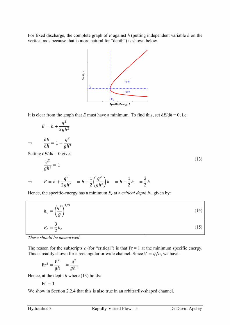
For fixed discharge, the complete graph of E against h (putting independent variable h on the
vertical axis because that is more natural for “depth”) is shown below.
It is clear from the graph that E must have a minimum. To find this, set dE/dh = 0; i.e.
Setting dE/dh = 0 gives
(13)
Hence, the specific-energy has a minimum Ec at a critical depth hc, given by:
(14)
(15)
These should be memorised.
The reason for the subscripts c (for “critical”) is that Fr = 1 at the minimum specific energy.
This is readily shown for a rectangular or wide channel. Since , we have:
Hence, at the depth h where (13) holds:
We show in Section 2.2.4 that this is also true in an arbitrarily-shaped channel.
Dep
th, h
Specific Energy, E
Fr<1
Fr>1
hc
Ec
`

Hydraulics 3 Rapidly-Varied Flow - 6 Dr David Apsley
Since
if h is larger then, to preserve volume flow rate, V is smaller; both ensure that for depths
greater than the critical depth then Fr < 1 (subcritical). Similarly, for depths smaller than the
critical depth, Fr > 1 (supercritical).
● For a given flow rate there is a minimum specific energy, Ec, occurring at the critical
depth where Fr = 1.
● For any energy E > Ec there are two possible depths with the same E and q:
– a shallow (h < hc), high-speed flow with Fr > 1 (supercritical);
– a deep (h > hc), low-speed flow with Fr < 1 (subcritical).
These are called alternate depths.
2.2.2 Calculating the Alternate Depths
For a given specific energy E and discharge (per unit width) q, the alternate depths in a
rectangular channel are the subcritical and supercritical solutions of
(16)
This can, in principle, be rearranged as a cubic equation and solved directly (see Chanson’s
book). However, it is easily solved by iteration in a manner that deliberately isolates the
deeper or shallower positive solution.
For the subcritical (deep, slow) solution the first term on the RHS of (16) dominates, so
rearrange for iteration as:
and start iterating from a subcritical depth (e.g. h = E).
For the supercritical (shallow, fast) solution the second term
on the RHS of (16) dominates, so rearrange for iteration as:
and start iterating from a supercritical depth (e.g. h = 0).
Example.
A 3-m wide channel carries a total discharge of 12 m3 s
–1. Calculate:
(a) the critical depth;
(b) the minimum specific energy;
(c) the alternate depths when E = 4 m.
Dep
th, h
Specific Energy, E
Fr<1
Fr>1
hc
Ec
`

Hydraulics 3 Rapidly-Varied Flow - 7 Dr David Apsley
2.2.3 Flow Over a Bed Rise
The total head is
Under the rapidly-varied-flow assumption, the total head
is constant, so that, if the bed height zb increases, the
specific energy E must decrease by the same amount.
Qualitative changes in specific energy E and water depth h
can be determined simply from the shape of the E-h graph.
Subcritical:
As E decreases, h decreases; i.e. water depth
decreases over a bump.
Supercritical:
As E decreases, h increases; i.e. water depth
increases over a bump.
(You should be able to work out from the specific-energy graph what happens to the depth of
water if the bed of the channel is depressed rather than elevated.)
Strictly, we have shown in the subcritical case that the depth h decreases over a bump, but
this does not necessarily imply that the actual water level zs does likewise. However, it turns
out that changes in actual water level (dzs) have the same sign as the changes in depth (dh).
This can be deduced by considering the total head:
Considering differential changes:
Neglecting friction over short distances, total head is constant (dH = 0), so that
Hence, at constant head, dzs and dh have the same sign; i.e. depth increases/decreases if and
only if the water level increases/decreases.
subcritical
supercritical
Dep
th, h
Specific Energy, E
Fr<1
Fr>1
hc
Ec
`

Hydraulics 3 Rapidly-Varied Flow - 8 Dr David Apsley
2.2.4 Specific Energy in a Non-Rectangular Channel
In this section we consider specific energy for a non-rectangular channel and, in particular,
deduce that critical conditions (Fr = 1) will occur at the minimum specific energy …
provided that we use the mean depth in the definition of the Froude number.
Let the cross-sectional area occupied by fluid be A and the surface width be bs.
The total head is
where . Hence,
where
(h is the depth at whichever point of the cross-section is used to determine the bed level zb:
usually the lowest point or invert.)
The specific energy has a minimum when dE/dh = 0. Now, by the chain rule,
Consider the area added when the depth is increased by dh,
Hence, at the minimum specific energy,
Since Q/A = V and A/bs = this gives
Hence, minimum specific energy for a given discharge occurs at Fr = 1, provided that we
define
(17)
This is the rationale for taking as the length scale used to define the Froude number.
bs
dh
A
b
A
s

Hydraulics 3 Rapidly-Varied Flow - 9 Dr David Apsley
2.2.5 Critical Conditions and Maximum Discharge
Previously we looked at the variation of specific energy with depth for constant discharge.
We can also look at the variation of discharge with depth for constant energy.
Rearranging (12) for the discharge:
The graph of q vs h for constant specific energy has the shape shown.
From the graph it is clear that q must have a maximum. Since q2 is largest when q is largest it
is easier to maximise q2 instead:
Setting gives
or
Thus, the maximum discharge for given energy also occurs where h, q and E are related by
(14) and (15). Hence, we note the following.
● For a given specific energy there is a maximum discharge, occurring at the critical
depth where Fr = 1.
Dep
th, h
Discharge per unit width, q
Fr>1
Fr<1hc
qmax

Hydraulics 3 Rapidly-Varied Flow - 10 Dr David Apsley
2.3 Critical-Flow Devices
A simple analysis is presented for 3 critical-flow devices:
broad-crested weir;
venturi flume;
sluice gate;
and one additional critical-flow control:
free overfall.
In each case, under suitable conditions, the flow passes smoothly from subcritical to
supercritical as it passes through the device. Since there is then a known relationship between
flow depth and discharge these hydraulic structures can be used to:
(i) meter the flow;
(ii) provide a control point (i.e. boundary condition) for GVF calculations.
For a broad-crested weir or venturi flume, when critical conditions are established the
specific energy – and hence the immediate upstream head – is fixed. This must be greater
than or equal to the head in the absence of the device and hence the fluid must “back up”; i.e.
the depth increases for some distance upstream. The flow is then said to be controlled or
choked by the device.
In the analyses below it is assumed that changes take place over a length short enough for
frictional losses to be negligible; i.e. the total head is constant through the device. In reality,
departures from this are often accommodated by the use of discharge coefficients in formulae
for discharge.
For simplicity, channels will be assumed to have rectangular (or wide) cross-section.
WEIR
total-head line

Hydraulics 3 Rapidly-Varied Flow - 11 Dr David Apsley
2.3.1 Broad-Crested Weir
Consider subcritical flow (with specific energy Ea, discharge per unit width q) approaching a
region where the bed is raised by Δzb. This region is sufficiently long for parallel flow to be
established (hence “broad-crested”), but insufficiently long for significant frictional losses.
As total head (H = zb + E) is constant, the
specific energy is reduced over the weir (to
). If this still exceeds the minimum
specific energy Ec for this discharge then the
flow remains subcritical over the bump and
resumes its original depth downstream.
If, however, the bed rise is sufficiently large
then, as the specific energy cannot be less
than Ec, the upstream flow must “back up”,
increasing the depth and specific energy
immediately upstream of the weir.
In the latter case we have the following (writing Δzb = zweir):
critical flow over the top of the weir with:
depth
specific energy
smooth acceleration from subcritical to supercritical flow either side of the weir;
total head immediately up or downstream of the weir is the same as that over the top:
the depths immediately up or downstream of the weir (where the bed level has
returned to zero) can be found as the sub- and supercritical solutions, respectively, of
What happens further up- or downstream depends on other controls (if present), or normal
flow if there are long fetches. An example for a long channel with subcritical normal flow is
shown below. Upstream, the flow relaxes via GVF. Downstream, it jumps back to subcritical
flow following a length of GVF. If any downstream controls are sufficiently far away then
the flow jumps directly back to its “preferred” depth for the channel; i.e. normal depth.
However, this cannot always be assumed: for shorter fetches, e.g. in the hydraulics laboratory
flumes, the downstream depth will not be normal; the flumes are nowhere near long enough.
WEIR
normal GVF
normal
hydraulicjump
hnch
1h
2h GVF
CP CP
hn
WEIR
WEIR

Hydraulics 3 Rapidly-Varied Flow - 12 Dr David Apsley
To establish whether the flow becomes critical over the weir, compare total head assuming
critical conditions at the crest of the weir (Hc) with the total head available in the approach
flow (Ha). (Often, but not always, this will be the head associated with normal flow).
In the approach flow find the specific energy Ea. If you are referring heights to the bed of the
channel near the weir then this will be the same as the approach-flow total head Ha at the
position of the weir.
At the weir find the critical depth hc and minimum
specific energy Ec. Then do one of the following.
(1) Find what the approach-flow specific energy
would be reduced to following the bed rise:
Ea – zweir
If this is less than the critical value Ec then
the flow must become choked and a critical-
flow transition will occur across the weir.
(2) Alternatively, find the total head associated
with critical flow over the weir; i.e.
This is the minimum head needed to pass this discharge over the weir. If it exceeds
the head available in the approach flow (Ha = Ea) then critical conditions occur and a
flow transition (sub- to supercritical flow) takes place across the weir.
Neglecting frictional losses, the total head H is constant across the device and equal to the
larger of the head under critical conditions and the head in the approach flow. This head,
together with the level of the bed and knowledge of whether the flow is subcritical or
supercritical, will determine the depth at a specific location.
Example. (Exam 2009 – reworded and extended)
(a) Define specific energy and explain its relevance in determining critical conditions in a
channel flow.
A long, wide channel has a slope of 1:1000, a Manning’s n of 0.015 m–1/3
s and a discharge of
5 m3 s
–1 per metre width.
(b) Calculate the normal depth.
(c) Calculate the critical depth.
(d) In a region of the channel the bed is raised by a height of 0.5 m over a length
sufficient for the flow to be parallel to the bed over this length. Determine the depths
upstream, downstream and over the raised bed, ignoring any friction losses. Sketch
the flow, including gradually-varied flow upstream and downstream.
(e) In the same channel, the bed is lowered by 0.5 m from its original level. Again,
determine the depths upstream, downstream and over the lowered bed, ignoring any
friction losses. Sketch the flow.
Dep
th, h
Specific Energy, E
hc
Ec
Ea
margin

Hydraulics 3 Rapidly-Varied Flow - 13 Dr David Apsley
Supercritical flow downstream of the weir may or may not actually occur.
If the flow far downstream is subcritical then in between there must be a hydraulic jump. If
conditions downstream of the jump are known (e.g. if normal flow) then the depth just
upstream of the jump can be calculated from the hydraulic-jump sequent-depth relationship.
A region of supercritical GVF downstream of the weir will exist provided the hydraulic jump
is not too close. The lectures on GVF will show that depth increases in supercritical flow on a
mild slope (one for which the normal depth is subcritical). Hence, this will occur if and only
if the supercritical depth just downstream of the weir is less than the depth upstream of the
jump. Otherwise, the hydraulic jump will occur immediately at the downstream base of the
weir, and there is no intervening region of supercritical GVF.
Denote the depth immediately downstream of the weir by h2 and the sequent depth on the
upstream side of the hydraulic jump by hJ. There are two possible cases:
(i) h2 < hJ: region of supercritical GVF
between the weir and the jump;
(ii) h2 ≥ hJ: jump occurs immediately
downstream of the weir; no region
of supercritical GVF (and the flow
depth may never actually reach h2).
It is therefore necessary to calculate and compare h2 (the depth of any supercritical parallel
flow just downstream of the weir) and hJ (the depth upstream of the jump, which is fixed by
the hydraulic jump relation, equation (7), and the depth downstream of the jump).
Example.
A long channel of rectangular cross-section with width 3.5 m and streamwise slope 1 in 800
carries a discharge of 15 m3 s
–1. Manning’s n may be taken as 0.016 m
–1/3 s. A broad-crested
weir of height 0.7 m is constructed at the centre of the channel. Determine:
(a) the depth far upstream of the weir;
(b) the depth just upstream of the weir;
(c) whether or not a region of supercritical gradually-varied flow exists downstream of
the weir.
WEIR
h1
hydraulicjump
hJWEIR
h2h1
hydraulicjump

Hydraulics 3 Rapidly-Varied Flow - 14 Dr David Apsley
Measurement of Discharge
If critical conditions are established over a weir
there is a fixed relationship between head and flow
rate, and the weir can be used for flow measurement.
Assuming no loss of head,
Because the upstream side is often a deep reservoir rather than a continuous channel (see the
figure below) it is more common for this purpose to measure the vertical coordinate z from
the top of the weir. Then, assuming critical flow over the crest of the weir:
where is the freeboard; i.e. the upstream depth relative to the weir. (If you
measure z from the bed of the channel instead then you would simply add zweir to both sides.)
This can be rearranged to give an implicit equation for the discharge per unit width:
Losses may be compensated for by a discharge coefficient cd. Then, in metre-second units,
the total discharge (Q = qb) is given by
(18)
This must be solved for Q by iteration (although the dynamic head on the RHS is usually
small and is often neglected). A straightforward measurement of water level then allows the
discharge in a channel to be gauged.
If the weir is discharging a deep reservoir
rather than a channel then the upstream head is
simply the still-water level and no iteration is
necessary – see the example below.
Example.
A reservoir has a plan area of 50 000 m2. The outflow passes over a broad-crested weir of
width 8 m and discharge coefficient 0.9. Calculate:
(a) the discharge when the level in the reservoir is 0.6 m above the top of the weir;
(b) the time taken for the level of water in the reservoir to fall by 0.3 m.
h1
WEIR
freeboard, h0
total-head line
WEIR
freeboard, h0
total-head line
RESERVOIR

Hydraulics 3 Rapidly-Varied Flow - 15 Dr David Apsley
2.3.2 Venturi Flume
In a duct or channel a region of contracted width is called
a venturi.
As a channel narrows the discharge per unit width,
q = Q/b, increases. It can be seen from the q-h graph at
constant specific energy that this cannot exceed the
maximum discharge qmax at this specific energy, which
occurs at critical conditions (Fr = 1). Where it is projected
to do so, the flow again becomes choked and critical
conditions are maintained at the venturi throat, with the
flow backing up upstream to provide a greater depth and
specific energy in order to pass the required flow.
If critical conditions occur we have the following.
There is smooth acceleration from sub- to supercritical flow through the throat.
At the venturi throat:
depth where
specific energy
Remember: qm is not the same as in the main channel.
The total head through the device is
where zb is the bed level (often, but not always, 0).
The depths of parallel flow in the vicinity of the venturi can then be found as the sub-
or supercritical solutions of
where b is the width at that particular location.
bmin
critical
PLAN VIEW
WATER PROFILED
ep
th, h
Discharge per unit width, q
Fr>1
Fr<1hc
qmax
Hydraulics 3 Rapidly-Varied Flow - 16 Dr David Apsley
To establish whether critical conditions occur, calculate the head Hc corresponding to critical
conditions at the throat and compare with the head Ha in the approach flow. If the approach-
flow head is smaller than that corresponding to critical flow in the throat then the flow must
back up and a critical-flow transition occurs. If the approach-flow head is larger than that
required by critical flow in the throat then critical conditions do not occur; for subcritical
approach flow the surface just dips and then returns to its original level.
As for the broad-crested weir the total head through the device is assumed to be constant and
equal to the larger of the approach-flow and critical heads.
Provided critical flow is established at its throat, a venturi flume can, like a broad-crested
weir, be used as a flowmeter.
Example. (Exam 2008 – modified, including a change in the value of n)
A venturi flume is placed near the middle of a long rectangular channel with Manning’s
n = 0.012 m–1/3
s. The channel has a width of 5 m, a discharge of 12.5 m3 s
–1 and a slope of
1:2500.
(a) Determine the critical depth and the normal depth in the main channel.
(b) Determine the venturi flume width which will just make the flow critical at the
contraction.
(c) If the contraction width is 2 m find the depths just upstream, downstream and at the
throat of the venturi flume (neglecting friction in this short section).
(d) Sketch the surface profile.

Hydraulics 3 Rapidly-Varied Flow - 17 Dr David Apsley
2.3.3 Sluice Gate
At the gate the flow passes smoothly through critical conditions from subcritical to
supercritical flow. Neglecting frictional losses, the total head is the same on both sides:
Provided the gate is not lifted too high then, in a rectangular channel with V = q/h and flat
bed from which z is measured, depths h1 and h2 are the subcritical and supercritical solutions
respectively, of
(19)
(Note that, because of the hydrostatic assumption implicit in the expression for total head, h2
is the depth where parallel flow has become established; i.e. at the vena contracta.)
Example.
The water depth upstream of a sluice gate is 0.8 m and the depth just downstream (at the vena
contracta) is 0.2 m. Calculate:
(a) the discharge per unit width;
(b) the Froude numbers upstream and downstream.
Example.
A sluice gate controls the flow in a channel of width 2 m. If the discharge is 0.5 m3 s
–1 and
the upstream water depth is 1.5 m, calculate the downstream depth and velocity.
In the general case, (19) can be rearranged for q and hence the total discharge (Q = qb):
(20)
In the “ideal” approximation, h2 is approximated by gate opening D and h2 << h1, so that
D
h1
total head line
h2
gate

Hydraulics 3 Rapidly-Varied Flow - 18 Dr David Apsley
In reality, h2 is much smaller than the gate opening (typically, about 0.6 times), h2/h1 is small
but not insignificant, and there are frictional losses. These modifications are all absorbed into
a discharge coefficient cd such that the actual, measured discharge can be written
(21)
The gate opening (D) and either upstream total head H or depth h1 control the discharge.
If the gate is opened too far, or if a downstream obstruction
is too close, then the hydraulic jump occurs immediately and
supercritical conditions cannot be attained. The flow on both
sides is then subcritical, there is energy lost and the sluice
gate is said to be drowned.
2.3.4 Free Overfall
If the approach flow is supercritical (Fr > 1) then
there is upstream control and the supercritical
flow simply continues over the overfall.
If the approach flow is subcritical (Fr < 1) then
the flow accelerates smoothly through critical to
supercritical flow a short (and usually
neglected) distance upstream of the overfall.
h1
hc
hc critical

Hydraulics 3 Rapidly-Varied Flow - 19 Dr David Apsley
2.4 Forces On Objects
Obstacles (e.g. bridge piers, baffle blocks) placed in the flow provide a reactive force.
For subcritical approach flow, depth of flow is reduced over a bed rise. This may be enough
to generate a critical-flow transition similar to that over a weir.
For supercritical approach flow, depth increases over a bed rise. If the flow has insufficient
head then a hydraulic jump occurs to a subcritical depth, with overall loss of energy.
Baffle blocks are used in stilling basins to provoke a hydraulic jump in a controlled and
precisely-located manner, so that the high-speed flow and/or the turbulent motions in the
jump do not cause damaging erosion further downstream.
Forces may be determined using a control-volume analysis and the momentum principle.
Where pressure is hydrostatic, the magnitude of the pressure force is (for a rectangular
channel of width b):
Then, from the steady-state momentum principle:
Hence,
(22)
This can also be written1
(23)
where
1 In the past M + Fp has sometimes been referred to as specific force. This will not be used here because:
(a) “specific” usually means “per unit mass, volume or weight” – which this isn’t; (b) the definition is not
consistent with most references in the literature; (c) the terminology is unnecessary.
BAFFLEBLOCKh1
V1
h2 V2

Hydraulics 3 Rapidly-Varied Flow - 20 Dr David Apsley
A hydraulic jump is just a special case of this analysis with F = 0; i.e.
This can also be used to establish the jump relation in non-rectangular channels.
Example. (Exam 2018)
Water flows at 0.8 m3 s
–1 per metre width down a long, wide spillway of slope 1 in 30 onto a
wide apron of slope 1 in 1000. Manning’s roughness coefficient n = 0.014 m–1/3
s on both
slopes.
(a) Find the normal depths in both sections and show that normal flow is supercritical on
the spillway and subcritical on the apron.
(b) Baffle blocks are placed a short distance downstream of the slope transition to
provoke a hydraulic jump. Assuming that flow is normal on both the spillway and
downstream of the hydraulic jump, calculate the force per metre width of channel that
the blocks must impart.
(c) Find the head loss across the blocks.
A hydraulic jump may also be triggered by a sudden expansion – e.g. a downward step or
abrupt increase in width. This can again be analysed by use of the momentum principle, with
the reaction force from the downstream-facing expansion walls approximated by a
hydrostatic-pressure distribution, as in the example below.
Example.
A downward step of height 0.5 m causes a hydraulic
jump in a wide channel when the depth and velocity
of the flow upstream are 0.5 m and 10 m s–1
,
respectively.
(a) Find the downstream depth.
(b) Find the head lost in the jump.
h12h