Embed Size (px)
Citation preview
Parallel Unfolding and Visualization of Curved Surfaces Extracted
from Large 3D VolumesOscar Figueiredo1, Roger D. Hersch2
1 CPE Lyon, 43 bd du 11 Novembre 69616 Villeurbanne Cedex (France)[email protected]
2 Ecole Polytechnique Fédérale de Lausanne (EPFL), CH-1015 Lausanne (Switzerland)[email protected]
Abstract. Although many 3D medical imaging visualization methods exist, 3D volume slicing remains the most commonlyused technique for visualizing medical data from modalities such as CT, MRI and PET. We propose to extend the possibilitiesof oblique slicing to developable curved surfaces that can be flattened and displayed in 2D without deformation. Such surfacescan be used to follow curved anatomical structures while preserving distance metrics at visualization time. They may also beuseful for the staging of tumors, i.e. to evaluate the spatial extension of a tumor. We propose an out of core algorithm that runsin parallel on a multi-PC architecture and is able to extract surfaces from very large 3D datasets such as the Visible Human dataset (man: 13 GB, woman: 49 GB). Experimental performance results are presented which demonstrate that parallel surface ex-traction is scalable and has a reasonable overhead compared with traditional oblique planar slicing. Surface extraction is madeavailable to the public as one of the services offered by EPFLs Visible Human Web Server (http://visiblehuman.epfl.ch).
Keywords. Medical imaging, curved anatomic structures, oblique slicing, surface extraction, surface unfolding, out of core par-allel processing.
1 Introduction
Biomedical imaging modalities such as CT, MRI and PET produce series of evenly spaced parallel slices which are examinedside by side by physicians, mentally rebuilding a spatial representation of the scene. In order to offer more flexibility, slices canbe stacked to build a 3D volume which allows for instance the extraction of planar slices of arbitrary orientation (an operationcalled multiplanar reprojection) [1]. However, there are many cases where oblique planar slices do not allow to adequately fol-low anatomic structures. In contrast to planar slices, surfaces offer the possibility of tracking and visualizing curved anatomicstructures. For instance, a surface is needed to visualize the connection between Superior Vena Cava, Right Atrium and InferiorVena Cava (see Appendix B). In addition, extraction of surfaces from tomographic volume images (CT, MRI) may prove to beuseful for the staging of tumors, i.e. for delimiting the extension of a tumor in order to evaluate possible therapeutic options.
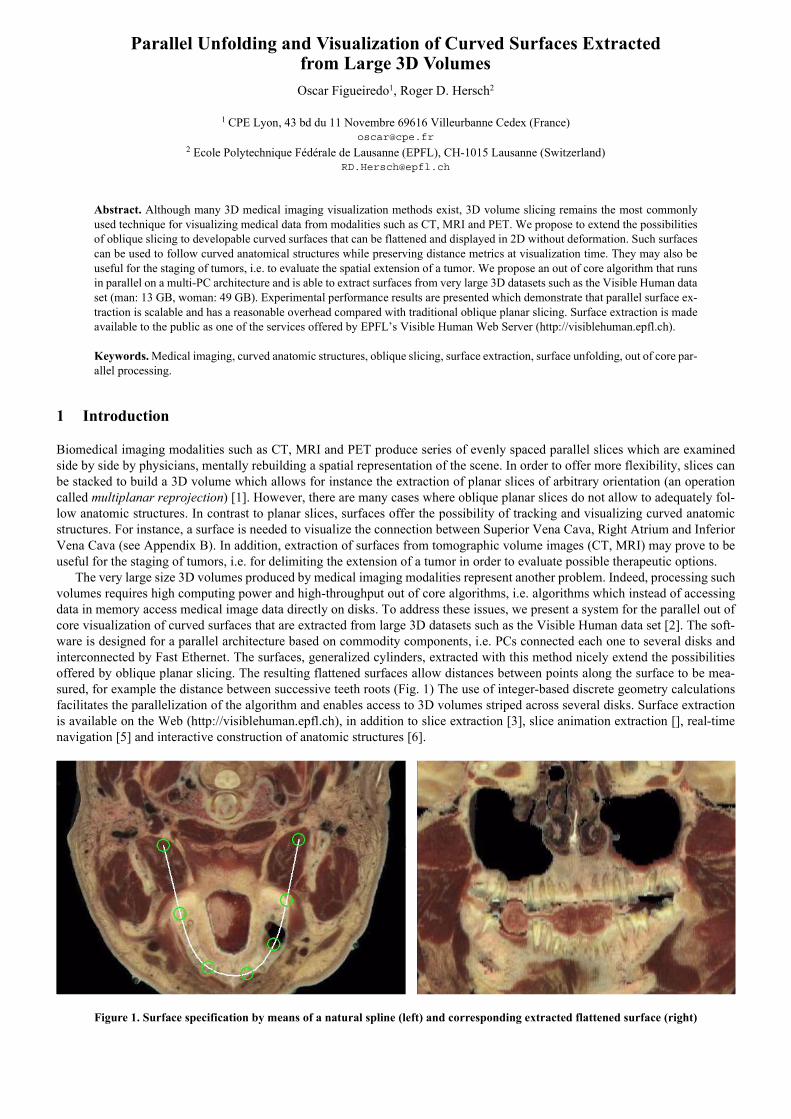
The very large size 3D volumes produced by medical imaging modalities represent another problem. Indeed, processing suchvolumes requires high computing power and high-throughput out of core algorithms, i.e. algorithms which instead of accessingdata in memory access medical image data directly on disks. To address these issues, we present a system for the parallel out ofcore visualization of curved surfaces that are extracted from large 3D datasets such as the Visible Human data set [2]. The soft-ware is designed for a parallel architecture based on commodity components, i.e. PCs connected each one to several disks andinterconnected by Fast Ethernet. The surfaces, generalized cylinders, extracted with this method nicely extend the possibilitiesoffered by oblique planar slicing. The resulting flattened surfaces allow distances between points along the surface to be mea-sured, for example the distance between successive teeth roots (Fig. 1) The use of integer-based discrete geometry calculationsfacilitates the parallelization of the algorithm and enables access to 3D volumes striped across several disks. Surface extractionis available on the Web (http://visiblehuman.epfl.ch), in addition to slice extraction [3], slice animation extraction [], real-timenavigation [5] and interactive construction of anatomic structures [6].
Figure 1. Surface specification by means of a natural spline (left) and corresponding extracted flattened surface (right)
In section 2, we introduce the concepts of ruled surfaces and digital cylinders. In section 3, we present the basic methods for
extracting and unfolding surfaces. In section 4, we describe two approaches for the parallel out of core extraction of surfaces. Theperformance analysis is carried out in section 5 and the conclusions are drawn in section 6.
2 From Oblique Slices to Digital Cylinders
2.1 Developable surfaces and cylinders
A special class of surfaces, called developable surfaces, is of particular interest for visualization purposes since these surfacescan be unfolded and flattened without deformation. Mathematically speaking, developable surfaces are ruled surfaces havinga constant tangent plane along each ruling. Ruled surfaces are themselves differentiable maps defined by a curve in anda parameterized family of directions of :
(1)
The curve is called the directrix of the surface while the family of lines passing through and parallel to are called rulings of the surface. Among developable surfaces we shall focus on cylinders. A cylinder is a ruled surface whosedirectrix is contained in a plane and whose rulings are of constant direction. Note that this notion encompasses but is not restrictedto circle-based cylinders. In the present application, we use spline-based cylinders. If we restrict ourselves to the case of cylinderswhose rulings are normal to the directrix plane, user interaction for the specification of the surface to be extracted becomes sim-ple. The plane containing the directrix can be specified by using the same user interface as the one used for the extraction ofoblique planar slices [3]. The directrix itself needs to be defined as a 2D curve on plane . This can be done for example bydefining a spline by means of interpolation points. Due to the simplicity of their specification, spline-based cylindric surfaces areparticularly well-suited for unfolding and visualization.
2.2 Digital cylinders
Several approaches are possible for extracting cylindric surfaces from 3D voxel-based volumes. One may use 3D texture map-ping, which allows mapping 2D and 3D images onto free-form surfaces [7]. This technique can be hardware-accelerated [9].However, generally, the size of the 3D texture is limited to the size of the available main memory. In addition, 3D rendering en-gines do not support the unfolding of surfaces, i.e. they generate surface projections which are not fully exploitable by physicianssince projections do not preserve the original surface geometry (distances and angles).
Kaufman et al. proposed several algorithms to perform the 3D scan-conversion of various geometric objects including free-form Bézier surfaces [8]. Their method consists in incrementally drawing the voxels derived from the continuous surface equa-tion. Error accumulation in incremental fixed-point or floating-point algorithms may yield ambiguous rasterizations, i.e. raster-izations which depend on the scanning direction [9]. We need to ensure that surface parts extracted in parallel from several sub-volumes precisely fit side by side. We therefore base our algorithms on discrete geometry [10], where only rational numbers hav-ing integer numerators and denominators are used. Algorithms derived from discrete geometry are efficient since they use integerarithmetic and avoid the pitfalls incurred by going back and forth between the discrete and continuous spaces. The rigorous def-initions for digital lines and planes given in [10] and [11] have been used to derive an efficient incremental parallel oblique sliceextraction algorithm [12]. The definition and discrete geometry representation of complex digital surfaces is however a more dif-ficult problem. For the purpose of cylinder surface extraction, we represent a digital surface by a mesh of digital polygons [13].In the same way as a digital curve is strictly equivalent to a discrete polygonal line, i.e., a sequence of digital straight line seg-ments, a thin digital surface can be conveniently represented as a sequence of digital plane patches. Thanks to the geometric prop-erties of cylinders, we can easily determine the equivalent representation of a digital cylinder by a mesh of adjacent digital planepatches.
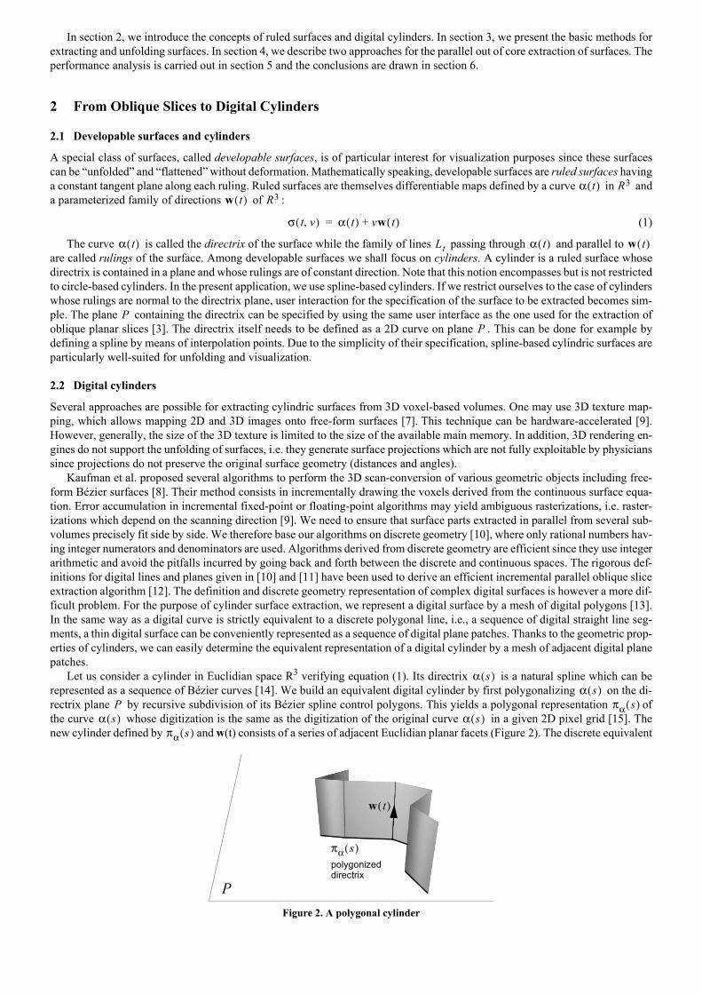
Let us consider a cylinder in Euclidian space R3 verifying equation (1). Its directrix is a natural spline which can berepresented as a sequence of Bézier curves [14]. We build an equivalent digital cylinder by first polygonalizing on the di-rectrix plane by recursive subdivision of its Bézier spline control polygons. This yields a polygonal representation ofthe curve whose digitization is the same as the digitization of the original curve in a given 2D pixel grid [15]. Thenew cylinder defined by and w(t) consists of a series of adjacent Euclidian planar facets (Figure 2). The discrete equivalent
Figure 2. A polygonal cylinder
α t( ) R3
w t( ) R3
σ t v,( ) α t( ) vw t( )+=
α t( ) Lt α t( ) w t( )
PP
α s( )α s( )
P πα s( )α s( ) α s( )
πα s( )
πα s( )
w t( )
P
polygonized directrix
to this surface, called the digital cylinder, is the union of a set of digital plane patches (digital facets), each fitting one of the Eu-clidian facets in the sense of a best approximation of an Euclidean plane by a naive digital plane [11].
The extraction of cylindric surfaces can be seen as an extension of the planar slicing problem: planar facets are extracted andcombined together to render the final flat non-distorted view of the cylinder surface. To respect the original surface geometry(distances), successive facets need to be resampled according to a single continuous 2D grid traversing the facets boundaries (sec-tion 3).
3 Surface Extraction
3.1 Algorithm overview
It should be possible to extract surfaces from virtually unlimited 3D volume sizes. We therefore describe surface extraction from3D volumes distributed over multiple disks. We consider the 3D Visible Human cryosection data set comprising 1840 1mmspaced slices, each scanned at a resolution of 3 pixels/mm, yielding slices of size 2048x1216 pixels. The 3D Visible Human dataset is reorganized into sub-volumes called extents of size 32x32x17 RGB voxels1. Extents are distributed across the availabledisks using the PS2 parallel file striping system [16] so as to provide a high degree of load balancing2 between the contributingdisks [17].
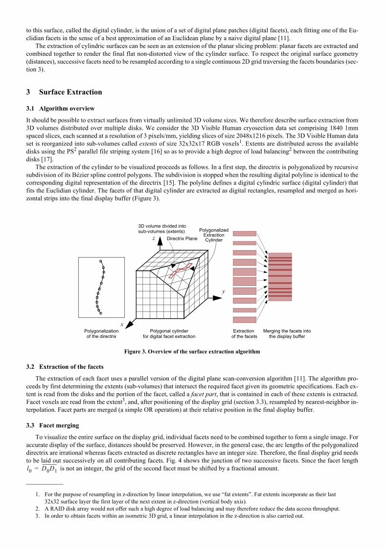
The extraction of the cylinder to be visualized proceeds as follows. In a first step, the directrix is polygonalized by recursivesubdivision of its Bézier spline control polygons. The subdivision is stopped when the resulting digital polyline is identical to thecorresponding digital representation of the directrix [15]. The polyline defines a digital cylindric surface (digital cylinder) thatfits the Euclidian cylinder. The facets of that digital cylinder are extracted as digital rectangles, resampled and merged as hori-zontal strips into the final display buffer (Figure 3).
3.2 Extraction of the facets
The extraction of each facet uses a parallel version of the digital plane scan-conversion algorithm [11]. The algorithm pro-ceeds by first determining the extents (sub-volumes) that intersect the required facet given its geometric specifications. Each ex-tent is read from the disks and the portion of the facet, called a facet part, that is contained in each of these extents is extracted.Facet voxels are read from the extent3, and, after positioning of the display grid (section 3.3), resampled by nearest-neighbor in-terpolation. Facet parts are merged (a simple OR operation) at their relative position in the final display buffer.
3.3 Facet merging
To visualize the entire surface on the display grid, individual facets need to be combined together to form a single image. Foraccurate display of the surface, distances should be preserved. However, in the general case, the arc lengths of the polygonalizeddirectrix are irrational whereas facets extracted as discrete rectangles have an integer size. Therefore, the final display grid needsto be laid out successively on all contributing facets. Fig. 4 shows the junction of two successive facets. Since the facet length
is not an integer, the grid of the second facet must be shifted by a fractional amount.
1. For the purpose of resampling in z-direction by linear interpolation, we use fat extents. Fat extents incorporate as their last 32x32 surface layer the first layer of the next extent in z-direction (vertical body axis).
2. A RAID disk array would not offer such a high degree of load balancing and may therefore reduce the data access throughput.
Figure 3. Overview of the surface extraction algorithm
3. In order to obtain facets within an isometric 3D grid, a linear interpolation in the z-direction is also carried out.
Directrix Plane
Polygonalizationof the directrix
Polygonal cylinder for digital facet extraction
Extraction of the facets
Merging the facets intothe display buffer
x
y
zPolygonalized
ExtractionCylinder
3D volume divided intosub-volumes (extents)
l0 D0D1=
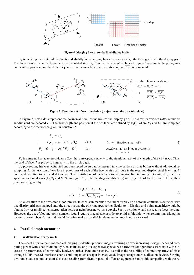
By translating the center of the facets and slightly incrementing their size, we can align the facet grids with the display grid.The facet translation and enlargement are calculated starting from the real size of each facet. Figure 5 represents the polygonal-ized surface projected on the directrix plane and shows how the translation is computed.
In Figure 5, small dots represent the horizontal pixel boundaries of the display grid. The directrix vertices (after recursivesubdivision) are denoted . The new length and position of the i-th facet are defined by where and are computedaccording to the recurrence given in Equation 2.
(2)
is computed so as to provide an offset that corresponds exactly to the fractional part of the length of the i-1th facet, Thus,the grid of facet is properly aligned with the display grid.
By proceeding this way, extracted and resampled facets can be merged into the surface display buffer without additional re-sampling. At the junction of two facets, pixel lines of each of the two facets contribute to the resulting display pixel line (Fig. 4)and need therefore to be blended together. The contribution of each facet to the junction line is simply determined by their re-spective fractional sizes ( and in Figure 5b). The blending weights and of facets and at theirjunction are given by
(3)
An alternative to the presented algorithm would consist in mapping the target display grid onto the continuous cylinder, withone display grid axis mapped onto the directrix and the other mapped perpendicular to it. Display grid point intensities would beobtained by resampling. i.e. interpolation between neighbouring volume voxels. Such a solution would not require facet merging.However, the use of floating-point numbers would require special care in order to avoid ambiguities when resampling grid pointslocated at extent boundaries and would therefore make a parallel implementation much more awkward.
4 Parallel implementation
4.1 Parallelization framework
The recent improvements of medical imaging modalities produce images requiring an ever increasing storage space and com-puting power which has traditionally been available only on expensive specialized hardware configurations. Fortunately, the in-crease in performance of commodity hardware such as Pentium-based PCs as well as the possibility of connecting arrays of disksthrough EIDE or SCSI interfaces enables building much cheaper interactive 3D image storage and visualization devices. Stripinga volumic data set onto a set of disks and reading from them in parallel offers an aggregate bandwidth compatible with the re-
Figure 4. Merging facets into the final display buffer
Figure 5. Conditions for facet translation (projection on the directrix plane)
D0
x
y
zl0
l1
Final display bufferFacet 1Facet 0
Overlap
n0
n1d0
d1Ω0
Ω1
P
D1
D2l0l1
P αi FiDi=
P
d0 d1d2
D0
D1
D2
D3
F0
F1
F2
G0
G1
G2
n0
n1 n2
D1F1 G0
E0
H1F1D1 E0D1=
D1H1 D1G0=
E0D1 D1H1+ 1=pixelwidth
pixelwidth
grid continuity condition:
=>
(a) (b) (c)
Di FiGi Fi Gi
F0 D0=
FiDi frac Fi 1 Di( )= i 1;≥
Fi 1 Gi 1 ceil Fi 1 Di( )= i 1;≥
frac(x): fractional part of x
ceil(x): smallest integer greater or equal to x
Fii
E0D1 D1H1 wi i( ) wi i 1+( ) i i 1+
wi i( ) Fi 1+ Di 1+=
wi i 1+( ) Di 1+ Hi 1+ = 1 wi i( )=
quirements of medical imaging. Furthermore, several PCs can be connected through commodity network switches such as FastEthernet and provide scalable computing power for algorithms designed to run in parallel. To achieve the best performance on amulti-PC multi-disk architecture, I/O intensive algorithms may hide disk transfer times by pipelining asynchronous disk accessesand computations.
In order to speedup the development of parallel applications and to specify parallel I/O and processing operations at a highlevel of abstraction, we use the Computer-Aided Parallelization (CAP) tool [17]. This tool enables application programmers tohierarchically specify the schedules of parallel operations and the flow of parameters and data between operations. Operationsconsist of sequential code performed by a single execution thread and characterized by input and output values. The input andoutput values of an operation are called tokens. In the context of this paper, tokens consist of image data (3D or 2D) and of addi-tional application dependent parameters. Each parallel CAP construct consists of a split function splitting an input request intosub-requests sent in a pipelined parallel manner to the operations of the available threads and of a merge function collecting theresults. The merge function also acts as a synchronization means terminating its execution and passing its result to the higherlevel program after the arrival of all sub-results.
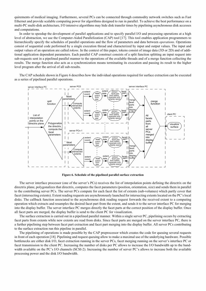
The CAP schedule shown in Figure 6 describes how the individual operations required for surface extraction can be executedas a series of pipelined parallel operations.
Figure 6. Schedule of the pipelined parallel surface extraction
The server interface processor (one of the servers PCs) receives the list of interpolation points defining the directrix on thedirectrix plane, polygonalizes that directrix, computes the facet parameters (position, orientation, size) and sends them in parallelto the contributing server PCs. The server PCs compute for each facet the list of extents (sub-volumes) which partly cover thatfacet (intersecting extents). Extent reading requests are asynchronously launched for intersecting extents located on the PCs localdisks. The callback function associated to the asynchronous disk reading request forwards the received extent to a computingoperation which extracts and resamples the desired facet part from the extent, and sends it to the server interface PC for merginginto the display buffer. The server interface PC merges directly the facet parts at the correct position of the display buffer. Onceall facet parts are merged, the display buffer is send to the client PC for visualization.
The surface extraction is carried out in a pipelined parallel manner. Within a single server PC, pipelining occurs by extractingfacet parts from extents while new extents are read from disks. Since facet parts are merged on the server interface PC, there isa further pipelining step between facet part extraction and facet part merging into the display buffer. All server PCs contributingto the surface extraction run this pipeline in parallel.
The pipelining of operations is made possible by the CAP preprocessor which creates the code for queuing several requestsin front of each operation [18]. Pipelining and request queuing allow to make a maximal use of the underlying hardware. Possiblebottlenecks are either disk I/O, facet extraction running in the server PCs, facet merging running on the servers interface PC orfacet transmission to the client PC. Increasing the number of disks per PC allows to increase the I/O bandwidth up to the band-width available on the PCs I/O channels (SCSI-2). Increasing the number of server PCs allows to increase both the availableprocessing power and the disk I/O bandwidth.
visualize surface
List of interpolation points on the directrix plane
facetpart
mergefacet
into
buffer
extract
from extent,resample ontodisplay space
All facets
Polygonalizethe directrix,compute thefacet
splitfunction
mergefunctionCompute
intersectedextents
extentcoord.
extentdataread
extentfromdisk
facet part
facetpartextract
from extent,resample ontodisplay space
extentcoord.
extentdataread
extentfromdisk
facet partdisplay
parts
facetpart
mergefacet
into
buffer
extract
from extent,resample ontodisplay space
Computeintersected
extents
extentcoord.
extentdataread
extentfromdisk
facet part
facetpartextract
from extent,resample ontodisplay space
extentcoord.
extentdataread
extentfromdisk
facet partdisplay
parts
parameters
partsfrom all serverPCsmergedintodisplaybuffer
server PC0
server PCn-1
server interface PC
client PC
facetparameters
facetparameters
server interface PC
4.2 Improving the parallelization strategy
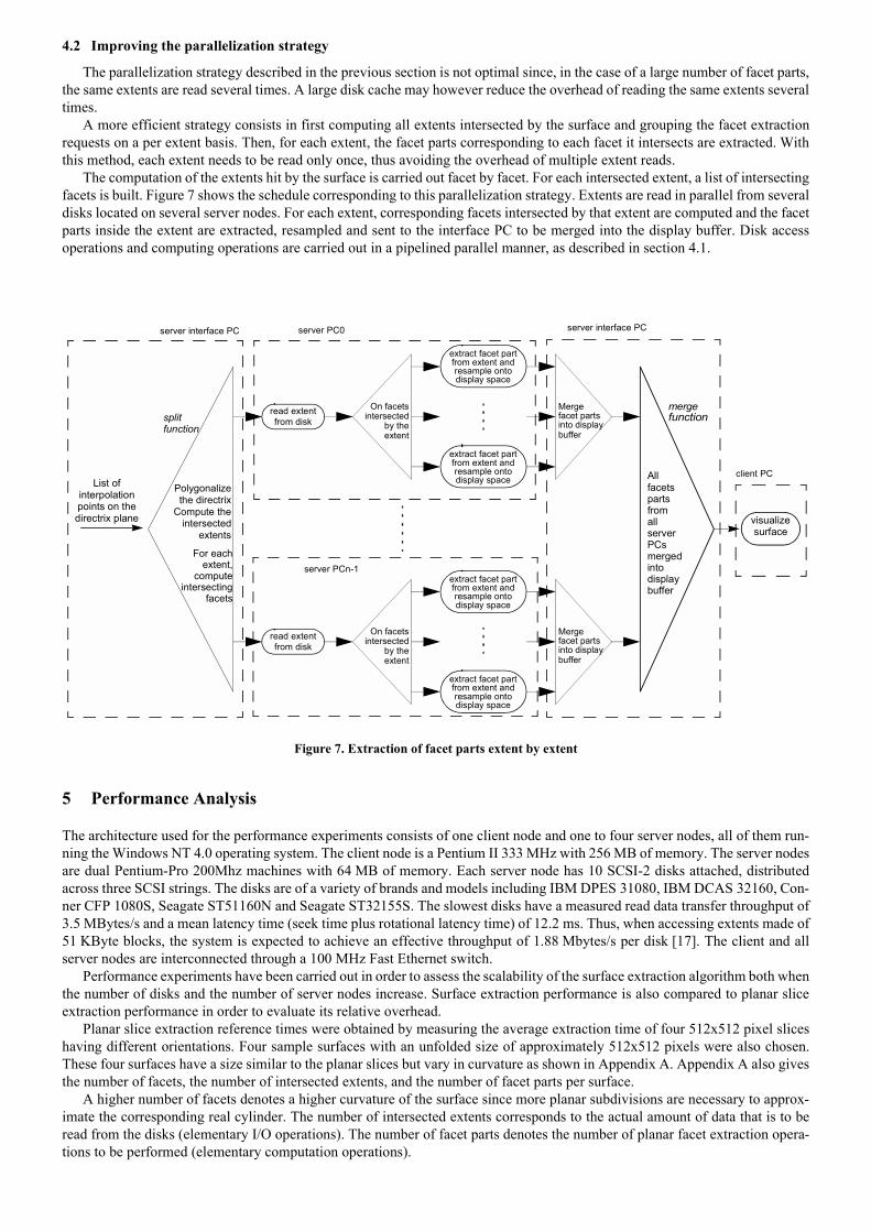
The parallelization strategy described in the previous section is not optimal since, in the case of a large number of facet parts,the same extents are read several times. A large disk cache may however reduce the overhead of reading the same extents severaltimes.
A more efficient strategy consists in first computing all extents intersected by the surface and grouping the facet extractionrequests on a per extent basis. Then, for each extent, the facet parts corresponding to each facet it intersects are extracted. Withthis method, each extent needs to be read only once, thus avoiding the overhead of multiple extent reads.
The computation of the extents hit by the surface is carried out facet by facet. For each intersected extent, a list of intersectingfacets is built. Figure 7 shows the schedule corresponding to this parallelization strategy. Extents are read in parallel from severaldisks located on several server nodes. For each extent, corresponding facets intersected by that extent are computed and the facetparts inside the extent are extracted, resampled and sent to the interface PC to be merged into the display buffer. Disk accessoperations and computing operations are carried out in a pipelined parallel manner, as described in section 4.1.
Figure 7. Extraction of facet parts extent by extent
5 Performance Analysis
The architecture used for the performance experiments consists of one client node and one to four server nodes, all of them run-ning the Windows NT 4.0 operating system. The client node is a Pentium II 333 MHz with 256 MB of memory. The server nodesare dual Pentium-Pro 200Mhz machines with 64 MB of memory. Each server node has 10 SCSI-2 disks attached, distributedacross three SCSI strings. The disks are of a variety of brands and models including IBM DPES 31080, IBM DCAS 32160, Con-ner CFP 1080S, Seagate ST51160N and Seagate ST32155S. The slowest disks have a measured read data transfer throughput of3.5 MBytes/s and a mean latency time (seek time plus rotational latency time) of 12.2 ms. Thus, when accessing extents made of51 KByte blocks, the system is expected to achieve an effective throughput of 1.88 Mbytes/s per disk [17]. The client and allserver nodes are interconnected through a 100 MHz Fast Ethernet switch.
Performance experiments have been carried out in order to assess the scalability of the surface extraction algorithm both whenthe number of disks and the number of server nodes increase. Surface extraction performance is also compared to planar sliceextraction performance in order to evaluate its relative overhead.
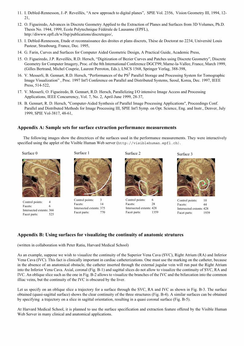
Planar slice extraction reference times were obtained by measuring the average extraction time of four 512x512 pixel sliceshaving different orientations. Four sample surfaces with an unfolded size of approximately 512x512 pixels were also chosen.These four surfaces have a size similar to the planar slices but vary in curvature as shown in Appendix A. Appendix A also givesthe number of facets, the number of intersected extents, and the number of facet parts per surface.
A higher number of facets denotes a higher curvature of the surface since more planar subdivisions are necessary to approx-imate the corresponding real cylinder. The number of intersected extents corresponds to the actual amount of data that is to beread from the disks (elementary I/O operations). The number of facet parts denotes the number of planar facet extraction opera-tions to be performed (elementary computation operations).
client PC
server PCn-1
List of interpolation points on the directrix plane
read extentfrom disk
extract facet partfrom extent andresample ontodisplay space
Polygonalizethe directrix
Compute theintersected
extents
On facetsintersected
extentby the
read extentfrom disk
Mergefacet partsinto display
On facetsintersected
extentby the
extract facet partfrom extent andresample ontodisplay space
extract facet partfrom extent andresample ontodisplay space
extract facet partfrom extent andresample ontodisplay space
Mergefacet partsinto display
buffer
buffer
visualize surface
All facetspartsfrom all serverPCsmergedintodisplaybuffer
server interface PC server interface PCserver PC0
splitfunction
mergefunction
For eachextent,
computeintersecting
facets
5.1 Varying the number of disks
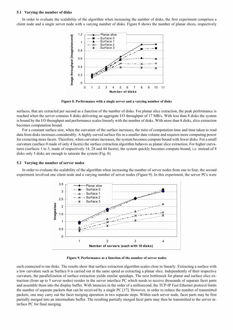
In order to evaluate the scalability of the algorithm when increasing the number of disks, the first experiment comprises aclient node and a single server node with a varying number of disks. Figure 8 shows the number of planar slices, respectively
surfaces, that are extracted per second as a function of the number of disks. For planar slice extraction, the peak performance isreached when the server contains 8 disks delivering an aggregate I/O throughput of 17 MB/s. With less than 8 disks the systemis bound by the I/O throughput and performance scales linearly with the number of disks. With more than 8 disks, slice extractionbecomes computation bound.
For a constant surface size, when the curvature of the surface increases, the ratio of computation time and time taken to readdata from disks increases considerably. A highly curved surface fits in a smaller data volume and requires more computing powerfor extracting more facets. Therefore, when curvature increases, the system becomes compute bound with fewer disks. For a smallcurvature (surface 0 made of only 4 facets) the surface extraction algorithm behaves as planar slice extraction. For higher curva-tures (surfaces 1 to 3, made of respectively 14, 28 and 44 facets), the system quickly becomes compute-bound, i.e. instead of 8disks only 5 disks are enough to saturate the system (Fig. 8).
5.2 Varying the number of server nodes
In order to evaluate the scalability of the algorithm when increasing the number of server nodes from one to four, the secondexperiment involved one client node and a varying number of server nodes (Figure 9). In this experiment, the server PCs were
each connected to ten disks. The results show that surface extraction algorithm scales close to linearly. Extracting a surface witha low curvature such as Surface 0 is carried out at the same speed as extracting a planar slice. Independently of their respectivecurvature, the parallelization of surface extraction yields similar speedups. The next bottleneck for planar and surface slice ex-traction (from up to 5 server nodes) resides in the server interface PC which needs to receive thousands of separate facet partsand assemble them into the display buffer. With latencies in the order of a millisecond, the TCP-IP Fast Ethernet protocol limitsthe number of separate packets that can be received by a single PC [17]. However, in order to reduce the number of transmittedpackets, one may carry out the facet merging operation in two separate steps. Within each server node, facet parts may be firstpartially merged into an intermediate buffer. The resulting partially merged facet parts may then be transmitted to the server in-terface PC for final merging.
Figure 8. Performance with a single server and a varying number of disks
Figure 9. Performance as a function of the number of server nodes
0
0.2
0.4
0.6
0.8
1
1.2
0 1 2 3 4 5 6 7 8 9 10 11Num ber of disks
Imag
e th
roug
hput
(im
ages
/sec
ond) Surface Average
Surface 0Surface 1Surface 2Surface 3
Planar slice
0
0.5
1
1.5
2
2.5
3
3.5
1 2 3 4Number of servers (each w ith 10 disks)
Imag
es/s
ec
Plane AverageSurface 0Surface 1Surface 2Surface 3
Planar slice
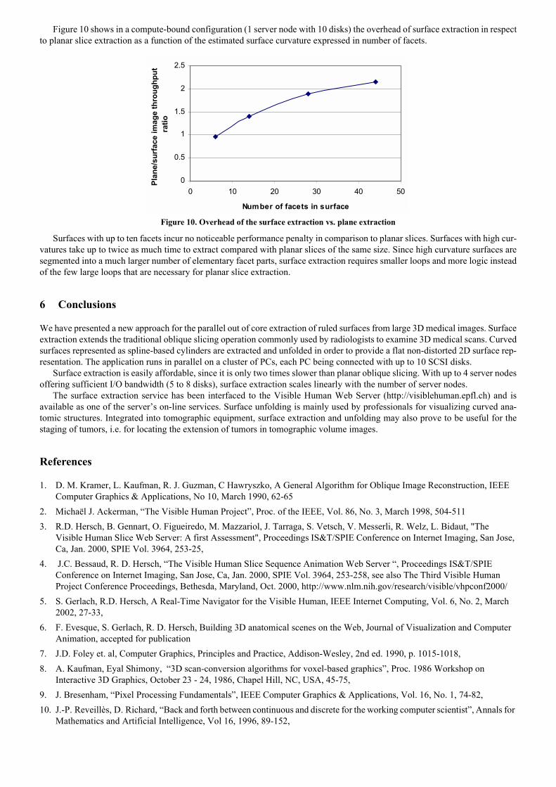
Figure 10 shows in a compute-bound configuration (1 server node with 10 disks) the overhead of surface extraction in respect
to planar slice extraction as a function of the estimated surface curvature expressed in number of facets.
Surfaces with up to ten facets incur no noticeable performance penalty in comparison to planar slices. Surfaces with high cur-vatures take up to twice as much time to extract compared with planar slices of the same size. Since high curvature surfaces aresegmented into a much larger number of elementary facet parts, surface extraction requires smaller loops and more logic insteadof the few large loops that are necessary for planar slice extraction.
6 Conclusions
We have presented a new approach for the parallel out of core extraction of ruled surfaces from large 3D medical images. Surfaceextraction extends the traditional oblique slicing operation commonly used by radiologists to examine 3D medical scans. Curvedsurfaces represented as spline-based cylinders are extracted and unfolded in order to provide a flat non-distorted 2D surface rep-resentation. The application runs in parallel on a cluster of PCs, each PC being connected with up to 10 SCSI disks.
Surface extraction is easily affordable, since it is only two times slower than planar oblique slicing. With up to 4 server nodesoffering sufficient I/O bandwidth (5 to 8 disks), surface extraction scales linearly with the number of server nodes.
The surface extraction service has been interfaced to the Visible Human Web Server (http://visiblehuman.epfl.ch) and isavailable as one of the servers on-line services. Surface unfolding is mainly used by professionals for visualizing curved ana-tomic structures. Integrated into tomographic equipment, surface extraction and unfolding may also prove to be useful for thestaging of tumors, i.e. for locating the extension of tumors in tomographic volume images.
References
1. D. M. Kramer, L. Kaufman, R. J. Guzman, C Hawryszko, A General Algorithm for Oblique Image Reconstruction, IEEE Computer Graphics & Applications, No 10, March 1990, 62-65
2. Michaël J. Ackerman, The Visible Human Project, Proc. of the IEEE, Vol. 86, No. 3, March 1998, 504-5113. R.D. Hersch, B. Gennart, O. Figueiredo, M. Mazzariol, J. Tarraga, S. Vetsch, V. Messerli, R. Welz, L. Bidaut, "The
Visible Human Slice Web Server: A first Assessment", Proceedings IS&T/SPIE Conference on Internet Imaging, San Jose, Ca, Jan. 2000, SPIE Vol. 3964, 253-25,
4. J.C. Bessaud, R. D. Hersch, The Visible Human Slice Sequence Animation Web Server , Proceedings IS&T/SPIE Conference on Internet Imaging, San Jose, Ca, Jan. 2000, SPIE Vol. 3964, 253-258, see also The Third Visible Human Project Conference Proceedings, Bethesda, Maryland, Oct. 2000, http://www.nlm.nih.gov/research/visible/vhpconf2000/
5. S. Gerlach, R.D. Hersch, A Real-Time Navigator for the Visible Human, IEEE Internet Computing, Vol. 6, No. 2, March 2002, 27-33,
6. F. Evesque, S. Gerlach, R. D. Hersch, Building 3D anatomical scenes on the Web, Journal of Visualization and Computer Animation, accepted for publication
7. J.D. Foley et. al, Computer Graphics, Principles and Practice, Addison-Wesley, 2nd ed. 1990, p. 1015-1018, 8. A. Kaufman, Eyal Shimony, 3D scan-conversion algorithms for voxel-based graphics, Proc. 1986 Workshop on
Interactive 3D Graphics, October 23 - 24, 1986, Chapel Hill, NC, USA, 45-75, 9. J. Bresenham, Pixel Processing Fundamentals, IEEE Computer Graphics & Applications, Vol. 16, No. 1, 74-82, 10. J.-P. Reveillès, D. Richard, Back and forth between continuous and discrete for the working computer scientist, Annals for
Mathematics and Artificial Intelligence, Vol 16, 1996, 89-152,
Figure 10. Overhead of the surface extraction vs. plane extraction
0
0.5
1
1.5
2
2.5
0 10 20 30 40 50
Number of facets in surface
Plan
e/su
rfac
e im
age
thro
ughp
ut
ratio
11. I. Debled-Rennesson, J.-P. Reveillès, A new approach to digital planes, SPIE Vol. 2356, Vision Geometry III, 1994, 12-
21, 12. O. Figueiredo, Advances in Discrete Geometry Applied to the Extraction of Planes and Surfaces from 3D Volumes, Ph.D.
Thesis No. 1944, 1999, Ecole Polytechnique Fédérale de Lausanne (EPFL), http://diwww.epfl.ch/w3lsp/publications/discretegeo/,
13. I. Debled-Rennesson, Etude et reconnaissance des droites et plans discrets, Thèse de Doctorat no 2234, Université Louis Pasteur, Strasbourg, France, Dec. 1995,
14. G. Farin, Curves and Surfaces for Computer Aided Geometric Design, A Practical Guide, Academic Press, 15. O. Figueiredo, J.P. Reveillès, R.D. Hersch, Digitization of Bezier Curves and Patches using Discrete Geometry, Discrete
Geometry for Computer Imagery, Proc. of the 8th International Conference DGCI'99, Marne-la-Vallee, France, March 1999, (Gilles Bertrand, Michel Couprie, Laurent Perroton, Eds.), LNCS 1568, Springer Verlag, 388-398,
16. V. Messerli, B. Gennart, R.D. Hersch, Performances of the PS2 Parallel Storage and Processing System for Tomographic Image Visualization , Proc. 1997 Int'l Conference on Parallel and Distributed Systems, Seoul, Korea, Dec. 1997, IEEE Press, 514-522,
17. V. Messerli, O. Figueiredo, B. Gennart, R.D. Hersch, Parallelizing I/O intensive Image Access and Processing Applications, IEEE Concurrency, Vol. 7, No. 2, April-June 1999, 28-37,
18. B. Gennart, R. D. Hersch, "Computer-Aided Synthesis of Parallel Image Processing Applications", Proceedings Conf. Parallel and Distributed Methods for Image Processing III, SPIE Int'l Symp. on Opt. Science, Eng. and Instr., Denver, July 1999, SPIE Vol-3817, 48-61,
Appendix A: Sample sets for surface extraction performance measurements
The following images show the directrices of the surfaces used in the performance measurements. They were interactivelyspecified using the applet of the Visible Human Web server (http://visiblehuman.epfl.ch).
Appendix B: Using surfaces for visualizing the continuity of anatomic strutures
(written in collaboration with Peter Ratiu, Harvard Medical School)
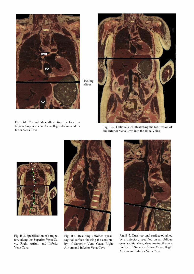
As an example, suppose we wish to visualize the continuity of the Superior Vena Cava (SVC), Right Atrium (RA) and InferiorVena Cava (IVC). This fact is clinically important in cardiac catheterizations. One must use the marking on the catheter, becausein the absence of an anatomical obstacle, the catheter inserted through the external jugular vein will run past the Right Atriuminto the Inferior Vena Cava. Axial, coronal (Fig. B-1) and sagittal slices do not allow to visualize the continuity of SVC, RA andIVC. An oblique slice such as the one in Fig. B-2 allows to visualize the branches of the IVC and the bifurcation into the commonilliac veins, but the continuity of the IVC is obscured by the liver.
Let us specify on an oblique slice a trajectory for a surface through the SVC, RA and IVC as shown in Fig. B-3. The surfaceobtained (quasi-sagittal surface) shows the clear continuity of the three structures (Fig. B-4). A similar surfaces can be obtainedby specifying a trajectory on a slice in sagittal orientation, resulting in a quasi coronal surface (Fig. B-5).
At Harvard Medical School, it is planned to use the surface specification and extraction feature offered by the Visible HumanWeb Server in many clinical and anatomical applications.
Surface 0 Surface 1 Surface 2 Surface 3
Control points: 6Facets: 28Intersected extents: 428Facet parts: 1359
Control points: 10Facets: 44Intersected extents: 428Facet parts: 1939
Control points: 4Facets: 6Intersected extents: 366Facet parts: 525
Control points: 3Facets: 14Intersected extents: 375Facet parts: 770
lackingslices
Fig. B-1. Coronal slice illustrating the localiza-tions of Superior Vena Cava, Right Atrium and In-ferior Vena Cava
Fig. B-2. Oblique slice illustrating the bifurcation ofthe Inferior Vena Cava into the Illiac Veins
Fig. B-3. Specification of a trajec-tory along the Superior Vena Ca-va, Right Atrium and InferiorVena Cava
Fig. B-4. Resulting unfolded quasi-sagittal surface showing the continu-ity of Superior Vena Cava, RightAtrium and Inferior Vena Cava
Fig. B-5. Quasi-coronal surface obtainedby a trajectory specified on an obliquequasi sagittal slice, also showing the con-tinuity of Superior Vena Cava, RightAtrium and Inferior Vena Cava
Appendix C: The Visible Human Web Server User Interface
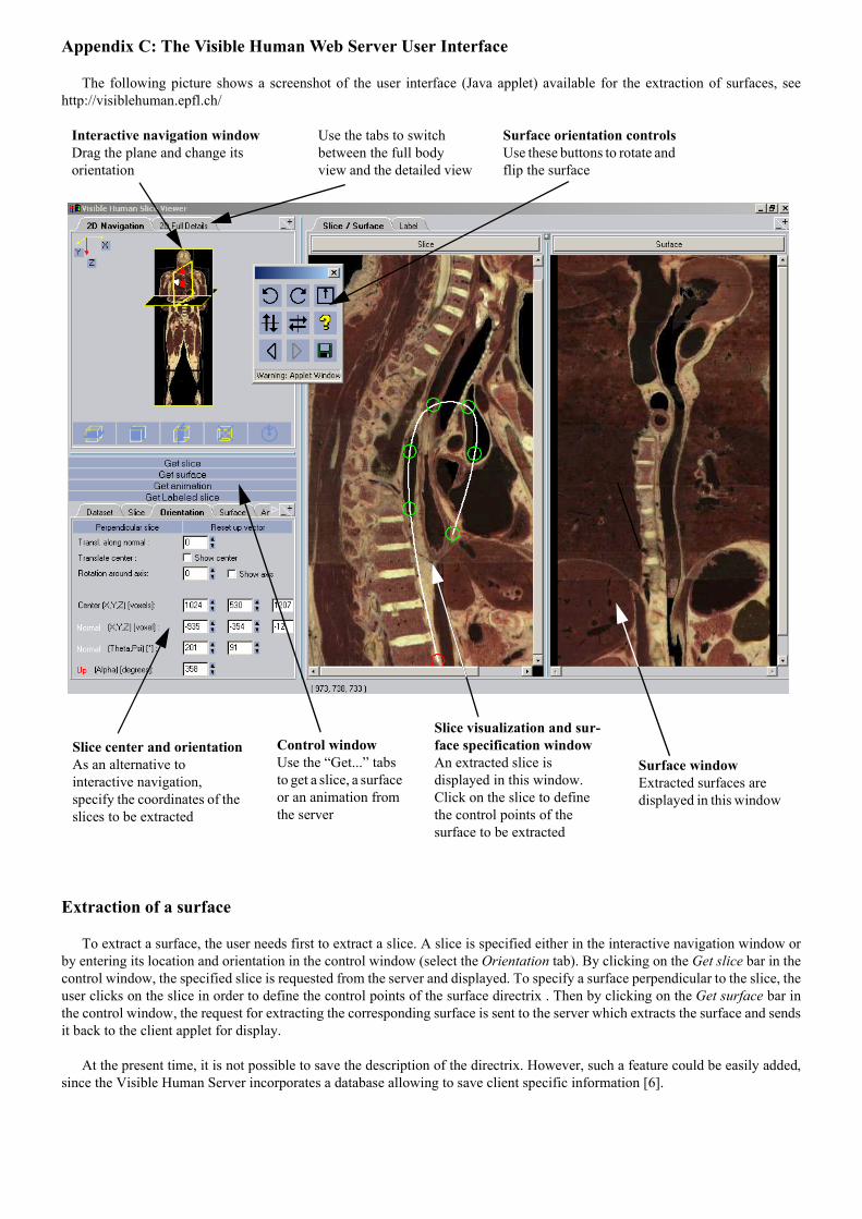
The following picture shows a screenshot of the user interface (Java applet) available for the extraction of surfaces, seehttp://visiblehuman.epfl.ch/
Extraction of a surface
To extract a surface, the user needs first to extract a slice. A slice is specified either in the interactive navigation window orby entering its location and orientation in the control window (select the Orientation tab). By clicking on the Get slice bar in thecontrol window, the specified slice is requested from the server and displayed. To specify a surface perpendicular to the slice, theuser clicks on the slice in order to define the control points of the surface directrix . Then by clicking on the Get surface bar inthe control window, the request for extracting the corresponding surface is sent to the server which extracts the surface and sendsit back to the client applet for display.
At the present time, it is not possible to save the description of the directrix. However, such a feature could be easily added,since the Visible Human Server incorporates a database allowing to save client specific information [6].
Interactive navigation windowDrag the plane and change its orientation
Use the tabs to switch between the full body view and the detailed view
Slice visualization and sur-face specification windowAn extracted slice is displayed in this window. Click on the slice to define the control points of the surface to be extracted
Control windowUse the Get... tabs to get a slice, a surface or an animation from the server
Surface windowExtracted surfaces are displayed in this window
Surface orientation controlsUse these buttons to rotate and flip the surface
Slice center and orientationAs an alternative to interactive navigation, specify the coordinates of the slices to be extracted