Embed Size (px)
Citation preview

•2? RECEIVED
Competi t ive Povyer Ventures, Inc.
FEB 0 2 2014
DEQ SWRO
January 31, 2014
Virginia Department of Environmental Quality Attention: Rob Feagins, Air Permit Manager Southwest Regional Office 355-A Dcadmorc Street Abingdon, Virginia 24210
RE: CPV Smyth Generation Company, LLC Prevention of Significant Deterioration Air Permit Application
Dear Mr. Feagins,
Please find enclosed four copies of CPV Smyth Generation Company, LLC's Prevention of Significant Deterioration Air Permit Application.
Per our previous discussions with you and Michael Kiss, this application includes the engineering portions of our PSD air permit application, including: the project description; potential emissions calculations and applicability determination; a review of state and federal air quality regulations to which the project is subject; Best Available Control Technology analysis; and, the VDEQ application forms, emissions calculation backup, and detailed equipment and vendor data. The air quality modeling analyses will be submitted1 separately, following completion of the collection of on-site meteorological data, as previously discussed.
Also enclosed for your information with this transmittal is our permit fee transmittal to the Virginia Department of Environmental Quality sent in parallel with this application.
We look forward to working with the Virginia Department of Environmental Quality on the review of CPV Smyth Generating Company, LLC's application.
Should you have any quest ions or in need o f any clarifications, please do not hesitate to contact me at your convenience.
Gener G. Gotiangco, P.E. [email protected] 240-723-2307"
C P V 'COMPETITIVE POWER VENTURES; INC.
8403 COLESVILLE ROAD SUITE 915 SILVER SPRING. MD 20910
V 240 723-2300 Fl 240 723-2339 WWW.CPV.COM

cc: M. Kiss, VA DEQ (via email) F. Sellars, Tetra Tech (via e-mail) R. Burke, Competitive Power Ventures, Inc. (via e-mail)
2
f^MMi
iPBEiilOTON OF S I S M f p l g i ^ PE##T APPLIGm W i '
CPV Smyth Generation! Company, LLC Atkins, Virginia
t
\~ Prepared on behalf of: *
#
CPV Smyth Generation Company, LLC 8403 Colesville Road, Suite 915 Silver Spring, MD 20910
For Submittal to:
Virginia Department of Environmental Quality Southwest Regional Office 355 Deadmore St. Abingdon, VA 24212
Prepared by:
TiETRATECH Tfc
TetraTech 160 Federal Street, 3 r d Floor Boston, MA 02110
January 2014

TABLE OF CONTENTS
ACRONYMS AND ABBREVIATIONS i
1.0 INTRODUCTION... 1-1
2.0 PROJECT DESCRIPTION 2-1 2.1 SiteCoeaudrii... 2-1 2.2 Prpj ect Description 2-1
3 0 AIR EMisSiONSi..... 3-1 3.1 Emission Sources . 3-1 3.2 Short-Term Emissions ...3-1
3.2. li Combustion Turbine and HRSG Units 3-1 3.2.2 Ancillary Equipment. 3-2
3.3 Annual1 Emissions 3-2 3.4 Hazardous Air Pollutant and Virginia Air Toxics Emissions 3-4
4.0 REGULATORY REVIEW AND APPLICABILITY 4-1 4.1 National Ambient Air Quality Standards 4-1 4.2 Prevention of Significant Deterioration Review 4-2 4.3 Nonattainment New Source Review 4-3 4.4 Virginia Minor Source Preconstruction Air Permitting (9 VAC 5-80) 4-4 4.5 New Source Performance Standards .4-4
4.5.1 40 CFR 60 Subpart KKKK 4-4 4.5.2 40 CFR 60 Subpart Dc. 4-5 4.5.3 40 CFR 60 Subpart II11 4-5
4.6 National Emission Standards for Hazardous Air Pollutants 4-5 4.7 Federal Add Rain Program 4-6 4.8 Title V Operating Permit 4-7 4.9 Compliance Assurance Monitoring. 4-7 4.10 Clean Air Interstate Rule 4-7 4.11 Federal Greenhouse Gas Reporting. ,. 4-8 4.12 Chemical Accident Prevention 4-8 4.13 Greenhouse Gas Permitting Requirements (9 VAC 5-85) 4-9 4.14 Virginia Air Toxics (9 VAC 5-60) 4-9
5.0 BEST AVAILABLE CONTROL TECHNOLOGY (BACT) ANALYSIS 5-1 5.1 Introduction : 5-1
5.1.1 Definition of BACT 5-1 5.1.2 BACT Process 5-1 5.1.3 Sources Reviewed To Identify BACT 5-2
5.2 Combined Cycle Combustion Turbines and Duct Burners ...5-3 5.2.1 Nitrogen! Oxides (NOx).. 5-3 5.2:2 Carbon Monoxide (CO) 5-6 5.2:3: Volatile Organic Compounds (VOCs)i .5-6 5;2:4! Particulate Matter (PM, PM,o, andPM^). .5-7 •:5;2c5: Sulfur Dioxide (S02) .5-8 5:2.6 Sulfuric Acid Mist!(H2S04) 5-8 5.2.7 Ammonia (NH3) 5-8 5 2.8 Greenhouse Gases 5-8 5.2.9 Summary of Proposed Combustion Turbine BACT Emission Rates 5-16 5.2.10 Startup/Shutdown (SU/SD) Emissions .....5-16
January 29, 2014

5.3 Auxiliary Boiler 5-17 5.3.1 Nitrogen Oxides (NOx)... 5-18 5.3.2 Carbon Monoxide (CO) ...5-18 5.3.3 Volatile Organic Compounds (VOCs) 5-20 5.3.4 Particulate Matter (PM, ;PM,0, and PM2 5) 5-20 5.3.5 Sulfur Dioxide (S02) and Sulfuric Acid Mist (H2S04) .5-20 5.3.6 Greenhouse Gases..: .5-20
5.4 Emergency Generator and Fire Pump Engines ............5-21 5.5 Fugitive GHG Emission Sources: .5-21
FIGURES
Figure 1-1 General Location Map .1-3 Figure 2-1 Equipment Arrangement Overview 2-2 Figure 5-1 C0 2 Pipelines in the United States 5-12
TABLES
Table 3-1: Short-Term Emission Rates for Turbine and HRSG Units (per unit) 3-2 Table 3-2: Short-Term Emission Rates for Ancillary Equipment 3-2 Table 3-3: Facility-Wide Annual Potential Emissions 3-3 Table 3-4: Summary of Startup/Shutdown Net Emissions Increase (Ib/hr) 3-4 Table 3-5: Summary of Potential HAP Emissions 3-4 Table 4-1: National and Virginia Ambient Air Quality Standards 4-2 Table 4-2: Prevention of Significant Deterioration Regulatory Threshold Evaluation ...4-3 Table 5-1: Summary Of Recent PSD Criteria PollutantBACT' Determinations for Large
'(> 100MW)| Gas Fired Combined-Cycle Generating Plants :...: 5-4 Table 5-2: Summary Of Recent PSD GHG BACT Determinations for Large (>100MW) Gas
Fired!Combined-Cycle Generating Plants. 5-14 Table 5-3: Proposed' Combustion Turbine BACT Emission Limits - Steady State Operation 5-16 Table 5-4: Transient Emission Limits! (lbs per event)...'. : v. ..5-17 Table 5-5: Summary Of Recent PSD Criteria Pollutant BACT Determinations for Natural
GasTFired Auxiliary Boilers....... ;....5-l'9 Table 5-6: Emergency Engine Emission Standards 5-21
APPENDICES
Appendix A VDEQ Air Permit Application Forms Appendix B Emission Calculations Appendix C Equipment Specifications and Vendor Performance Data

CPV Smyth Generation Project PSD Air Permit Application
ACRONYMS AND ABBREVIATIONS
ACC air cooled condenser
BAAQMD Bay Area Air Quality Management District BACT Best Available Control Technology BHP brake horsepower Btu/kW-hr British thermal unit per kilowatt-hour
CAA Clean Air Act CAIR Clean Air Interstate Rule CARS California Air Resources Board CCS carbon capture and storage CFR Code of Federal Regulations CEMS continuous emissions monitoring system CH4 methane CO carbon monoxide C0 2 carbon dioxide C02e carbon dioxide equivalent CPV Smyth CPV Smyth Generation Company, LLC CSAPR Cross State Air Pollution Rule CTG combustion turbine generator
DAHS data acquisition handling system DLN dry-low NOx
op degrees Fahrenheit
GHG greenhouse gases g/kW-hr grams per kilowatt-hour gr/lOOscf grains per 100 standard cubic feet
H 2S0 4 sulfuric acid H2S hydrogen sulfide HAP hazardous air pollutant HFCs hydrofluorocarbons HHV higher heating value HRSG heat recovery steam generator
kW kilowatt
LAER Lowest Achievable Emission Rate lb/MMBtu pound per million British thermal units Ib/MW-hr pound per megawatt-hour Ib/hr pounds per hour lbs pounds LLO Low Load Operation LNB low NOx burners
MACT Maximum Achievable Control Technology MMBtu million iBritish thermal units MMBtu/hr million British thermal units per hour MW megawatt
Tfc i

CPV Smyth Generation Project PSD Air Permit Application
ACRONYMS AND ABBREVIATIONS (Continued)
MWh megawatt-hour ug/m3 microgram; per cubic meter
NAAQS National Ambient Air Quality Standards NESHAP National Emission Standard for Hazardous Air Pollutants NH 3 ammonia N 2 0 nitrous oxide N0 2 nitrogen dioxide NOx nitrogen oxides NNSR Nbnattainment New Source Review NSPS New Source Performance Standards NSR New Source Review
0 2 oxygen 03 ozone
Pb lead PM particulate matter PM 2 5 particulate matter with an aerodynamic diameter of 2.5 micrometers or less PM10 particulate matter with an aerodynamic diameter of 10 micrometers or less ppm parts per million ppmyd @15% parts per million volume dry at 15% oxygen PSD Prevention of Significant Deterioration
RBLC RACTABACTALAER Clearinghouse
SAAC Significant Ambient Air Concentration SCR selective catalytic reduction SFfi sulfur hexafluoride SIP State Implementation Plan SG2 sulfur dioxide STG steam-turbine generator SU/SD start-up/shutdown operation SWRO Southwest Regional Office
TLV® Threshold Limit Value tpy tons per year
ULSD ultra low sulfur diesel USEPA United States Environmental Protection Agency UTM Universal Transverse Mercator
VAAQS Virginia Ambient Air Quality Standards VAC Virginia Administrative Code VDEQ Virginia Department of Environmental Quality VOC volatile organic compound

CPV Smyth Generation Company PSD Air Permit Application
1.0 INTRODUCTION
CPV Smyth Generation Company, LLC (CPV Smyth) proposes to construct and operate a nominal 700-megawatt (MW) natural gas-fired, combined-cycle generating facility in Atkins, Virginia. Construction of the CPV Smyth Generation Company (the Project) is scheduled to begin in early 2015 with commencement of commercial operation by mid-2017. The proposed project location is a greenfield site with no commercial history.
The proposed Project will include two natural gas-fired combustion turbine generators (CTGs), two heat recovery steam generators (HRSGs) and one steam turbine generator (STG). The Project will be configured as a "2 on 1" power block with steam from the two HRSGs feeding the single STG. The balance of the Project will include an auxiliary boiler, emergency generator engine, emergency fire pump engine, aqueous ammonia (NH3) storage tank, and an air cooled condenser (ACC).
The Project will have potential emissions above the Prevention of Significant Deterioration (PSD) major source threshold1 for nitrogen oxides (NOx), carbon monoxide (CO) and greenhouse gases (GHGs). As major source for NOx emissions, the Project will also be considered major for ozone. Potential emissions of all size fractions of particulate matter (PM/PM10/PM2.5), volatile organic compounds (VOCs) and sulfuric acid mist (H2S04) will be above their respective PSD significant emissions threshold. Therefore, the Project will be subject to PSD permitting for NOx, CO, PM/PM,o/PM2.5, VOC, H 2S0 4, and GHGs. CPV Smyth is applying for a PSD permit from the Virginia Department of Environmental Quality (VDEQ) for the Project. The PSD permit is required under 9 Virginia Administrative Code (VAC) 5-80, Part I I , Article 8 (9 VAC 5-80-1600 et seq.). This document, along with the accompanying VDEQ forms and other appended materials, is the PSD application for the Project. The Project will not be subject to Nonattainment New Source Review (NNSR) because the site is located in Smyth County, which is designated as unclassified or attainment for all criteria pollutants. This application addresses the permitting requirements specified by the VDEQ under 9 VAC 5, Chapters 80 and 85 as well as those contained in Title 40 of the Code of Federal Regulations (CFR) Part 52.21 (40 CFR 52.21).
Emissions of sulfur dioxide (S02) will be below its PSD significant emissions rate threshold but above the VDEQ de minirnis permitting thresholds based on uncontrolled potential emissions as specified in 9 VAC 5-80-1105. As a result, S02 emissions will trigger VDEQ Best Available Control Technology (BACT) requirements under 9 VAC 5-80 Part I I Article 6 and this application also addresses the VDEQ permitting requirements for these pollutants. For informational purposes and completeness, emissions have been quantified and BACT analyses have been completed for NH 3 emissions from the CTGs due to its use as the reagent in the selective catalytic reduction (SCR) systems proposed in the HRSGs of these units.
To facilitate VDEQ's review of this document, individuals familiar with the Project are identified below. The VDEQ should contact these individuals if additional information or clarification is required during the review process. These contacts include the primary contact for the project developer and consultant who were responsible for the preparation of this application.
CPV Smyth: Gener Gotiangco CPV Smyth Generation Company, LLC 8403 Colesville Road, Suite 915 Silver Spring, MD 20910 Telephone: (240) 723-2307 Email: [email protected]
rut 1-1

CPV Smyth Generation Company PSD Air Permit Application
Permitting Consultant: Steven J. Babcock, P H. Tetra Tech, Inc. 160 Federal Street, 3rd Floor Boston, MAi021i 10 Telephone: (617) 443-7533 Email: Steven :j [email protected]
This; application consists of the following five sections in addition to this Introduction:
o Section 2 provides a project description, including information regarding the plant's location and equipment design information;
o Section 3 provides a description of potential emissions and' the basis of calculation;
» Section 4 provides a review of state and federal air quality regulations applicable or potentially applicable to the Project;
o Section 5 iprovides the BACT analyses;
» Appendices A through C provide the VDEQ Forms, emission calculations, and detailed equipment and vendor data.
Provided in Figure 1-1 is a General Location Map showing the location of the Project and nearby area.
1-2

CPV Smyth Generation Company PSD Air Permit Application
Figure 1-1 General Location Map
f t 1-3


CPV Smyth Generation Company PSD Air Permit Application
2.0 PROJECT DESCRIPTION
2.1 Site Location
The proposed Project: will be constructed on a 108-acre parcel at a greenfield location in Atkins, VA. The site is located in east-central Smyth County, approximately 4 miles east-northeast of Marion, VA and approximately 0.5 miles south of Interstate 81. The site is in a rural valley at a 2,500 foot above mean sea level elevation with higher elevation mountains running generally in a southwest to northeast direction and located approximately 2 to 3 miles north and south of the property.
2.2 Project Description
The proposed nominal 700 MW1 combined-cycle natural gas-fired facility will be configured as two operating units. The power plant will be configured in a "2 on 1" power block configuration with steam from the two HRSGs feeding the single STG. The HRSGs will be equipped with duct burners (supplementary firing) to provide additional generating capacity during periods of peak demand. The facility is designed to run as a base load plant with both combustion turbines operating concurrently but the facility will have the capability of operating with a single combustion turbine.
The Project will include a variety of power plant equipment including: two natural gas-fired CTGs; one STG; two HRSGs with SCR and oxidation catalyst emissions control equipment; generator step-up transformers; an electrical switchyard; an NH 3 storage tank; water tanks; and an ACC. In addition, the Project will include other buildings for administrative and operating staff; warehousing of parts and consumables; and maintenance shops and equipment servicing. An overview of equipment arrangement on the site is provided as Figure 2-1.
The first stage in the generation process of a combined-cycle power plant is the operation of the CTGs. Thermal energy, in the form of hot exhaust gas, is produced in the CTGs through the combustion of natural gas. The hot exhaust gases are then converted into mechanical energy by a turbine that drives a generator. The exhaust gas temperature exiting the gas turbine is in excess of 1 ;000 degrees Fahrenheit (°F) and still has remaining a significant amount of recoverable heat energy. This heat energy is recovered in the HRSG by generating steam that is sent to a STG to generate additional electrical energy. The generation of electricity using both a gas turbine and steam turbine defines the combined cycle, which the most efficient form of electrical generation available. The efficiency of the facility is further enhanced by using reheat systems as well as waste energy to heat feedwater in the HRSG by an additional economizer loop and also for fuel preheating. Once the steam leaves the steam turbine, it is condensed back into water using an ACC and this condensed water is returned to the HRSGs to minimize water use. Additional steam, and consequently additional electricity, may be generated when required by the use of supplemental natural gas-fired burners (duct burners) within the HRSGs.
Each of the two CTGs that will be used by the Project is an Alstpm GT24 with a nominal generating capacity of 234 MW (at - 10°F ambient conditions). The CTGs wi l l be equipped with inlet air cooling via fogging and evaporative cooling or chillers. The single steam turbine will provide up to an additional 228 MW without duct firing (at -10°F ambient conditions) and 312 MW with duct firing in both HRSGs (90°F ambient conditions, at which the gas turbines produce 201 MW utilizing the chillers option installed and in operation).
1 Based on 90°F ambient temperature, 50% relative humidity, and duct firing.
Tt 2-1

CPV Smyth Generation Company PSD Air Permit Application
Figure 2-1 Equipment Arrangement Overview
2-2

o
o Figure 2-1 CPV Smyth Generation Company, LLC
Equipment Arrangement
Note: Site layout by Stantec Consulting Services, Inc.

CPV Smyth Generation Company K PSD Air Permit Application
Pollutant emissions from the Project will be minimized through the use of natural gas as the sole fuel to be fired in the CTGs and duct burners. Each HRSG will be equipped with; SCR and an oxidation catalyst to reduce emissions of NOx, and CO and VOC, respectively. The SCR system will utilize 19% aqueous NH 3 as the reagent in the SCR systems. Continuous emissions monitoring systems (CEMS)i will continuously sample, analyze, and record' exhaust gas concentrations of NOx, CO and NH 3 from each of the two HRSG exhaust flues. The CEMS will be installed and' operated in accordance with United States Environmental Protection Agency (USEPA); and VDEQ; requirements and will generate emissions data reports that will be consistent with anticipated permit requirements and send' alarm signals to plant supervisory and control systems when emissions approach or exceed permitted limits.
Ancillary equipment at the proposed Project will include three additional fuel combustion emission units:
• A 93 million British thermal unit per hour (MMBtu/hr) natural gas-fired auxiliary boiler equipped with ultra low-NOx burners;
• A 1,500 kilowatt (kW) (standby rating) emergency generator firing 15 parts per million (ppm) ultra low sulfur distillate (ULSD) oil; and
• A 315 brake horsepower (BHP) emergency fire pump engine firing ULSD oil.
To support the SCR systems, a 20,000 gallon above-ground storage tank will contain 19% aqueous NH 3. The tank will be located within a concrete containment structure (dike) along with the ammonia transfer pumps, valves and piping.
The Project will interconnect with the 765 kilovolt transmission line that crosses the northern portion of the site via a new switchyard. Natural1 gas will be delivered from the existing gas pipeline located approximately 1,5 miles to the north of the site. A pipeline lateral will be installed to bring the gas from the existing pipeline to the site.
2-3

CPV Smyth Generation Company PSD Air Permit Application
3.0 AIR EMISSIONS
This section presents short-term and long-term potential emissions from each emission source for the Project. Project emissions will be minimized through the application of BACT controls. CPV Smyth proposes to use dry low-NO* combustion and SCR to minimize NOx emissions from the combustion turbines. Combustion controls and an oxidation catalyst will be used to minimize CO and VOC emissions from the turbines. S0 2 and PM/PM10/PM25 will be controlled through the use of natural gas as the sole fuel for the turbines, duct burners and auxiliary boiler. ULSD oil will be used for the emergency generator and fire pump engines. Section 5 of this application contains control technology analysisJto demonstrate that these controls meet BACT requirements. Appendix B of this application contains detailed emission calculations and Appendix C contains equipment specifications and vendor performance data for the proposed emission sources.
3.1 Emission Sources
The emission sources for the Project will include:
• One combined cycle power generation unit, consisting of two combustion turbines (Alstom GT24) serving two associated HRSG's with duct burners and one common STG. The combined cycle power generation units will be equipped with: inlet air cooling via high fogging and evaporative cooling or chillers; SCR for NOx control; and an oxidation catalyst for control of CO and VOC;
o One natural gas fired auxiliary boiler rated at 93 MMBtu/hr, equipped with ultra low-NOx burners (Cleaver Brooks "Nebraska" D-type boiler or equivalent);
« One emergency generator rated at 1,500 kW (standby rating), firing ULSD oil (Caterpillar 3512C or equivalent);
o One fire pump engine rated at approximately 315 BHP, firing ULSD oil (Clarke JU6H-UFAD98 or equivalent); and
The following equipment will not have any potential air emissions under normal operation:
• ACC for condenser cooling; and
• One 20;000 gallon above ground aqueous NH 3 storage tank.
The facility will also include miscellaneous insignificant sources such as small ULSD and lubricant storage tanks, which will have insignificant emissions.
3.2 Short-Term Emissions
3.2.1 Combustion Turbine and HRSG Units
Short-term potential emission rates for each combined cycle unit, including the combustion turbine and associated duct burner, are presented in Table 3-1. The rates shown are based on 100% load operation at -10°F with duct burner firing, and represent the worst case operating scenario. Potential emission rates are presented in: parts per million by volume, dry basis (ppmvd), corrected to 15% oxygen (0 2); pounds per million British thermal units (lb/MMBtu) on a high heating value (HHV) basis; and pounds per hour
Ifc 3-1

CPV Smyth Generation Company PSD Air Permit Application
(Ib/hr). S0 2 emissions are based on a maximum natural gas sulfur content of 0.5 grains per 100 standard cubic feet (gr/100 scf).
Table 3-1: Short-Term Emission Rates for Turbine and HRSG Units (per unit)
Pollutant ppmvd at 15%0 2 lb/MMBtu Ib/hr1
NOx; 2.0 0.0074 19:6
CO 2.0 | 0.0045 j ; 11,9
VOC, unfired 1.0 0.0013 2.9
VOC, duct-fired 2.0 0.0026 6.8
S 0 2 013 0.0014 3.8
PM/ PM10/ PM2.5 . N/A N/A 12i9
Includes duct firing except VOC, unfired
3.2.2 Ancillary Equipment
Short-term potential emission rates for the auxiliary boiler; the emergency generator, and' the fire pump engine are presented in Table 3-2. Potential emission rates are presented in lb/MMBtu or grams per kilowatt-hour (g/kWh) as appropriate, and in Ib/hr.
Table 3-2: Short-Term Emission Rates for Ancillary Equipment
Pollutant
Auxiliary Boiler Emergency Generator Fire Pump
Pollutant lb/MMBtu Ib/hr g/kWh Ib/hr g/kWhi Ib/hr
| NOx 0:011 1.01 6.4 21.16 4.0 2.07
CO 0.037 3:42 3 5 11.57 3.5 1.91
VOC ; 0.005 ! 0.47 1.3 4:30 1.3 0.26
S 0 2 j 0.0014 0113 0.0015 lb/MMBtu 0:02 0.0015 lb/MMBtu 0003
PM/:PMio/ PM?.s 0.005 0.46 ; 0.2 ! 0:66 0.2 0.10
3.3 Annual Emissions
The proposed potential annual emissions from the Project are summarized in Table 3-3. Potential annual! emissions are based on the following operating assumptions:
• For the combustion turbines, 5,760 hours at 100% load, operating at 59°F, with no duct burner firing, and 3,000 hours at 100% load, operating at -10°F, with duct burner firing;
• For the auxiliary boiler, 4,000 hours at 100% load;
• For the emergency generator and fire pump engines, 500 hours each at maximum rated power;
# 3-2

CPV Smyth Generation Company PSD Air Permit Application
Table 3-3: Facility-Wide Annual Potential Emissions
Pollutant
ilff
=>
£x
-
Unit 2 (CTG & HRSG) (tpy)
Auxiliary Boiler (tpy)
Emergency Generator
(tpy)
Fire; Pump (tpy)
Facility.Total (tpy)
NOx 74.7 74,7 2:02 5.29' • 0.52 157.2
CO 47:7 47.7 6:83 2.89 0145 105.6
VOC 22,1 22:1 0:94 1.07 ' ; 006 46.3
S 0 2 132 13.2 0:26 0.005 0.001 26:6
PM/PM10/PM2.S 39:5 39.5 0.92 0,17 0.03 8011
Carbon dioxide equivalent (C0 2e)
1,156,440 1,156,440 21,627 592 90 2,335,189
H2SO4 8.6 8.6 0.02 0.0004 0.0001 17.3
Lead (Pb) 4.52-03 4.5E-03 9.1E-05 2.8E-06 42E-07 0.009
NH 3 65.2 65.2 N/A N/A N/A 130.3
Total HAPS 4.2 4.2 0.35 0:02 0.004 8.7
The combustion turbines have higher mass emissions of NOx, CO and' VOC during start-up and shutdown than during full-load operation. The impact of increased emissions during start-up and shutdown were evaluated to determine the total potential emissions for the Project, including startup and shutdown operation. Start-ups for combined-cycle systems are generally classified as cold, warm, and hot depending on the length of time the unit has been off-line prior to start-up. The length of start-ups will vary with the type of start-up and plant equipment temperatures.
The maximum number of starts per year per turbine was determined based upon turbine vendor recommendations and projected operation in the competitive power marketplace. Low Load Operation (LLO) is unique to Alstom's gas turbine featuring sequential combustion technology. For customers operating in markets where daily stop/starts and/or parking at low load are required, the LLO feature offers additional flexibility. LLO allows operators to park the entire plant down to 10% combined cycle power plant load with both CTGs and the STG in operation. Due to the sequential combustion technology, the emissions at the LLO point stay at BACT level emission rates. Compared to a 40-50% plant minimum load, which is the current industry standard, the LLO feature provides unique spinning reserve capability for the KA24-2 turbine, without a risk of start failure and without cyclic lifetime consumption of the gas turbine.' The LLO is achieved by switching off the second combustor, while the first combustor operates in its optimal point (thus producing base-load like emissions). For emissions purposes, switching off the second combustor,is considered "an event" similar to a startup or shutdown in that it has a defined period of transitional non-compliance before stabilizing at compliance levels: These transitional periods occur in both directions as the unit unloads to LLO and as the unit reloads to the normal minimum emission compliance point. This operating characteristic allows for cycling: down of the turbine during periods of low demand rather than shutting the unit down. As a result, the number of starts and stops for the Alstom GT24 turbine could be greatly reduced, which would result in a reduction in annual emissions for the Project.
Tfe 3-3

CPV Smyth Generation Company PSD Air Permit Application
The increase in emissions per type of start was quantified' using emissions and operating data provided' by Alstom. The increase in emissions for each type of start was then compared to the reduction in emissions associated with the minimum turbine downtime per type of startup/shutdown event. Any increase in start-up/shutdown (SU/SD) emissions quantified for each type of start was added to the potential emissions for continuous full load operation for 8,760 hours per year. This potential to emit approach represents the worst-case maximum potential to emit for the Project. The potential annual .emissions of NO%, CO and VOC in Table 3-3 include the higher emissions from either a conservative number of startup and shutdown cycles (250 hot starts, 50 cold starts, 300 shutdowns) per unit or 250 transition events ,per unit. Since emissions during cold and warm starts are self-correcting (i.e., SU/SD emissions are equal to or lower than full load steady state emissions when downtime is considered), it was conservatively assumed that the majority of starts would be hot starts. Table 3-4 provides a summary of SU/SD net emissions increases for the CTGs as compared to steady state operation. SU/SD emissions calculations are provided in detail in Appendix B.
Table 3-4: Summary of Startup/Shutdown Net Emissions Increase (Ib/hr)
Pollutant ColdiStart Warm; Start Hoti Start Shutdown i Transition to/from LLO
NOx ' N/A V N/A ' 4.07 0.05 N/A
CO N/A . / N/A • 4140 0.41 1.17
VOC j N/A N/A 4.08 0.65 2.23
As summarized above, there is a net increase in average hourly emissions during hot starts, shutdown and transition events. For NGX, CO and VOC emissions, a combined hot start and shutdown event provides higher hourly emissions than a transition event to and from LLO event so these were used in adjusting the plant's annual potential to emit.
3:4 Hazardous Air Pollutant and Virginia Air Toxics Emissions
Potential annual hazardous air pollutant '(HAP); emissions are presented in Table 3-5 for the Project. HAP is jdefined iin Section 112(b) under the Clean Air Act (CAA) Amendments of 1990; and for Virginia "air toxics", as modified The regulation of HAP emissions are administered by the VDEQ under 9 VAC 5 Chapter 60, Section 4 of this application provides a discussion of the applicability of 9 VAC 5 Chapter 60 to the Project. Total HAP emissions from the Project are 8.7 tpy; detailed HAP emissions calculations are provided in Appendix B.
Table 3-5: Summary of Potential HAP Emissions
HAP Potential Annual Emissions (tpy)
TOTALS HAP CTGs HRSGs
Auxiliary Boiler
"' Em. Generator Fire Pump TOTALS
Organic Compounds
Acetaldehyde 6.90E-01 5.18E-02 9.11 E-05 4.22E-04 7.42E-01 ! ' Acrolein 1.10E-01 8.28E-03 2.85E-05 5.09E-05 ; 1.19E-01 | Benzene 2.07E-01 1.55E-02 3.88E-04 2.81E-03 5.13E-04 ; 2.26E-01 1!;3-Butadiene 7.41 E-03 5.56E-04 2.152-05 | j 7.99E-03 Dichlorobenzene 2.22E-04 2:222-04 Ethylbenzene I 5.52E-01 4.14E-02 5:93E-01
3-4

CPV Smyth Generation Company PSD Air Permit Application
Table 3-5: Summary of Potential HAP Emissions
Potential Annual Emissions (tpy) HAP CTGs HRSGs
Auxiliary Boiler
Em. Generator
Fire Pump TOTALS
Formaldehyde 1.902+00 4:532-01 1.37E-02 2.852-04 : 6.49E-04 2.362+00
Hexane 3.332-0,1 I 3.332-01
Propyleneoxide 5.002-01 3.752-02 I 1.392-02 : | 1.96E-03 | 5.532-01
Toluene | 2.242+00 1.682-01 | | 6.10E-04 1.022-03 | 2.252-04 | 2.412+00
Xylene j 1.102+00 8.282-02 6.98E-04 I 1.572-04 | 1.192+00
PAHs
Acenaphthene | 3.332-07 1.692-05 | j 7,81 E-07 | 1.802-05
Acenaphthylene 4.442-07 3.342-05 | 2.78E-05 6.16E-05
Anthracene 3.33E-07 4.452-06 ! 1.03E-06 5.81 E-06
Benzo(a)anthracene 3.33E-07 2.252-06 9:24E-07 3.512-06
Benzo(a)pyrene 2.222-07 9.292-07 | 1.03E-07 1.252-06
Benzo(b)fluoranthene 3.33E-07 4.01 E-06 5.45E-08 4.402-06
Benzo(g,h,i)perylene 2.22E-07 2.01 E-06 2.69E-07 2.502-06
Benzo(k)fluoranthene 3.332-07 7.88E-07 8.53E-08 1.212-06
Chrysene 3.332-07 5.53E-06 1.94E-07 6.062-06
Dibenz(a,h)anthracene 2.222-07 1.25E-06 3:21 E-07 1.792-06
7,12-Dimethylbenz(a) anthracene 2.962-06 2.96E-06
Fluoranthene 5.362-07 1.46E-05 4.19E-06 1.932-05
Fluorene 4.992-07 4.632-05 1.61E-05 6.282-05
lndeno(1,2,3-cd)pyrene 3.332-07 1.50E-06 2:06E-07 2.042-06
3-Methylchloranthrene 3.332-07 3.332-07
2-Methylnaphthalene 4.442-06 4.442-06
Naphthalene 2.242-02 1.682-03 1.152-04 4.702-04 4.66E-05 2.472-02 |
Phenanthrene 3.142-06 1.48E-04 1.62E-05 1.672-04
ipyrene 9.062-07 1.34E-05 2.63E-06 1.692-05
TOTAL PAH 3:792-02 2.852-03 1.262-04 7.672-04 9:242-05 4.182-02
Metals
Arsenic 3:452-03 2.59E-04 3.702-05 1.672-07 2.542-08 3.742-03
Beryllium 2.072-04 1.55E-05 2.222-06 2.25E-04
Cadmium 1.902-02 1.42E-03 2.032-04 1.85E-08 2.822-09 2.06E-02
Chromium 2.412-02 1.81 E-03 2.592-04 4.48E-05 6.822-06 2.63E-02
Chromium VI 4.312-03 3.23E-04 4:622-05 8.10E-06 1.232-06 4.69E-03
Cobalt 1.412-03 1.06E-04 1.522-05 1.53E-03
Lead 8.452-03 6.34E-04 . 9J062-05 : 2.78E-06 4.232-07 9.132-03 [
Manganese 6.382-03 4.79E-04 6:842-05 1.02E-06 1.552-07 6.932-03
Mercury 4.312-03 3.232-04 4.622-05 3.72E-08 5.672-09 4.682-03
Nickel 3.622-02 2.72E-03 3.882-04 5.35E-06 8.14E-07 3.932-02
Selenium 4.142-04 3.112-05 4:442-06 9.26E-07 1.412-07 4.502-04
Max. Single HAP 2.4
Total All HAPs 782+00 8.7E-01 3.5E-01 2.0E-02 4.2E-03 8.7
3-5

CPV Smyth Generation Company PSD Air Permit Application
4:0 REGULATORY REVIEW AND APPLICABILITY
The USEPA and VDEQ have promulgated regulations that establish ambient air quality standards and emissions limits for sources of air pollution. This section of the application identifies the regulations that may apply to the Project and discusses how CPV Smyth will Comply with all applicable requirements.
The federal regulations reviewed here include; National Ambient Air Quality Standards (NAAQS); PSD and New.Source Review (NSR)! requirements; New- Source Performance Standards (NSPS); National! Emission Standards! for, Hazardous Air Pollutants (NESHAP); Acid'Rain Program; Title V Operating Permit Program; and the: Clean Air Interstate Rule (CAIR) / Cross State Air Pollution Rule (CSAPR).
4.1 National Ambient Air Quality Standards
The USEPA has developed NAAQS for six air contaminants, known as criteria pollutants, for the protection of public health and welfare. These criteria pollutants are S02, PM/PM10/PM2.5, nitrogen dioxide (N0 2), CO, ozone (O3), and Pb. The VDEQ also has adopted these limits as Virginia Ambient Air Quality Standards (VAAQS) under 9 VAC 5 Chapter 30. The NAAQS have been developed for short-term periods of 24 hours or less and annual averages. The NAAQS include both "primary" and "secondary" standards where the primary standards are set to protect human healthy allowing an adequate margin of safety. Secondary standards are set to protect the public welfare from any known or anticipated adverse effects associated with the presence of air pollutants in the ambient air. Provided in Table 4-1 are the NAAQS and VAAQS.
One of the primary goals of federal and state air pollution regulations is to ensure that ambient air quality is in compliance with the NAAQS. Toward this end, every area of the United States has been designated as attainment, unclassifiable, or nonattainment for each criteria pollutant. In areas designated as attainment, the air quality with respect to the pollutant is equal to or better than the NAAQS. These areas are under a mandate to maintain, i.e., prevent significant deterioration of, such air quality. In areas designated as unclassifiable, there is limited air quality data and these areas are treated as attainment areas for regulatory purposes. In areas designated as nonattainment for a particular pollutant, the air quality with respect to that pollutant is worse than the NAAQS. These areas must take actions to improve air quality and attain the NAAQS within a certain period of time.
If a new major source of air pollution is proposed, it must undergo NSR air permitting. The NSR air permitting regulations contain two distinct programs, one for sources proposed in attainment/unelassifiable areas and one for sources in nonattainment areas. The NSR program for sources in attainment/unelassifiable areas is known as the PSD Program. The NSR program for sources being built in non-attainment areas is known as Nonattainment NSR or NNSR. The Project is located in an area classified! as "attainment" or "attainment/ unclassifiable" for all criteria pollutants. Thus, emissions of criteria pollutants from the Project are evaluated under the PSD program. The requirements of the PSD program are discussed in Section 4:2.
4-1

CPV Smyth Generation Company PSD Air Permit Application
Table 4-1: National and Virginia Ambient Air Quality Standards
r>/ t' ' Pollutant I 7j
f ^ W ^ I T ' t> M t t , ' * < f ( / / ' J <•
i f 1 Averaging Period^'
V ' , ^ NAAQS'AVAAQSt'ng/m3) ' x •>' 1
r>/ t' ' Pollutant I 7j
f ^ W ^ I T ' t> M t t , ' * < f ( / / ' J <•
i f 1 Averaging Period^' \ \ /'Primary 1 ^ Jvv. - Secondary ^ * j N 0 2 Annual1 100 Same N 0 2
1-hour2 li88 None sbz - - Annual1,3 . . 80 None sbz - -
24-hour3" 365 None
sbz - -
3-hour4 None 1,300
sbz - -
li-hour5'6 196 None P M 2 5 Annual7
' : 12 • Same P M 2 5
24-hour8 ! . 351 . Same PM.o 24-hour9 I 150 Same CO 8-hour4 10,000 None CO
1-hour4 | 40,000 None 0 3 8-hr10 !•• • 147 Same Pb , 3-month1 ! 0.15 Same 1 Notito be exceeded.
2 Compliance based on; 3-year average of the 98"" percentile of the daily maximum l.-hburiaverageiat each monitor within an area.
3 The 24-hour and annual average primary standards for SO; been revoked but remain in effect until one year after Smyth County has been designated for the 1-hour and 3-hour standards, whichhas yet to occur..
4 Not to be exceeded more than once: per year. 5 Compliance based on 3-hear average of 99"1 [percentile of the daiily maximum 1-hour average at each monitor
within an area: 6 The 1-hour S0 2 standard was;effective as of August 23, 2010. 7 Compliance basedjon.3-year average: of weighted annual mean P M 2 5 concentrations at community-oriented
monitors. 8 Compliance based on 3-year average of 98"1 percentile' of 24-hour concentrations at each population-oriented
monitor, within an area. 9 Not to'be:exceeded more than onceiper.year on ayerage;over3;years;;
1 0 : Compliance based on: 3-year average of fourth-highest daily maximum]8-hour average ozone;concentratiOns measured atieach monitor:within'an;area.,
4.2 Prevention of Significant Deterioration Review
The PSD Air Quality Program,: which is implemented by the VDEQ, is a federally mandated program review of major new sources of criteria and other PSD-regulated pollutants primarily designed to maintain attainment with the NAAQS and prevent degradation iof air quality in, attainment/unelassifiable areas. Under the PSD program,; a combined-cycle electric generation facility is considered a major source if emissions of any single Criteria pollutant are greater than 100 tons per year (tpy) or if GHG emissions exceed 100,000 tpy. The Project will have potential emissions greater than 100 tpy for one or more criteria pollutants and potential GHG emissions greater than 100;000 tpy. Therefore, the proposed Project will be subject to the requirements of the PSD program.
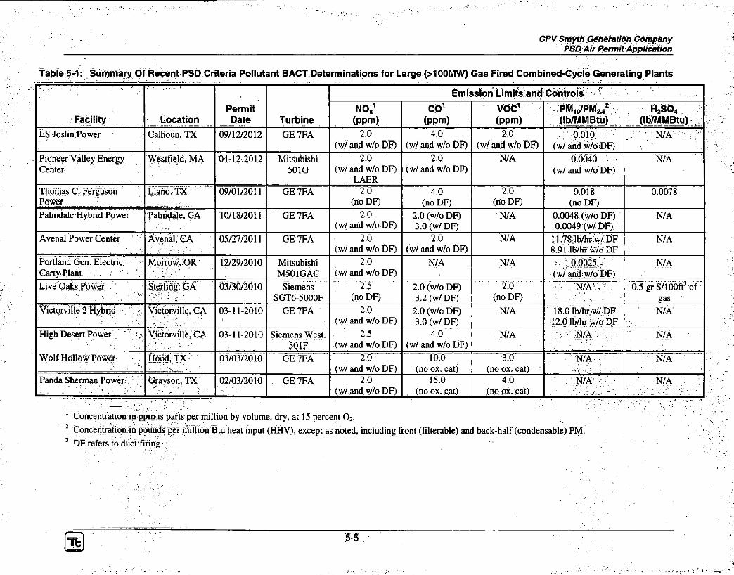
Once a project exceeds one of the PSD major source thresholds, the PSD regulations also apply to each criteria pollutant that is emitted in excess of its respective defined significant emission rate. Table 4-2 presents a comparison of the Project's potential emissions versus the PSD major source and significant emission rate thresholds. As shown in Table 4-2, the facility is subject to PSD review for NOx, CO,
I t 4-2
CPV Smyfh Generation Company PSD Air Permit Application
PM/PM10/PM2 5, VOC, H2SO4 and GHGs. (See Section 3.2 for the assumptions used in determining annual potential emissions.)
Table 4-2: Prevention of Significant Deterioration Regulatory Threshold Evaluation
_ tpf . J? % t*. % -{
^ ^. r -* g^* n ^ K i . ' -
yr^ * \ Pollutant /
^ Project Potential" J Annual *
r " Emissions ^ ; ^ ( t o n s )
"<PSD Major « Source
:- Threshold %, * (tons) ^
PSD 1
> Significant : Emission Rate
,-(tons) ^
, ^ f A * 1
PSD Review Applies?
CO 105.6 1 100 100 Yes
NO, 157.2 100 40 Yes
so2 26:6 100 40 No
PM 80.1 100 25 Yes
PM 1 0 80.1 100 15 Yes
PM 2 5 80:1 100 10 Yes
VOC (ozone precursor) 46.3 100 40 Yes
Sulfuric Acid Mist 17.3 100 7 Yes
GHGs (as COze) 2,335,189 100,000 75,000 Yes
Lead 0:009 100 0.6 No
Fluorides Negligible 100 3 No
Hydrogen Sulfide (H2S) none expected 100 10 No
Totals Reduced Sulfur (inc. H2S) none expected 100 10 No
Reduced Sulfur Compounds (inc. H2S) none expected 100 10 No
The key requirements for obtaining a PSD permit are a demonstration that BACT requirements are satisfied and an air quality impact analysis is completed to document compliance with the NAAQS and PSD increments, which are concentrations of allowable air quality degradation from a baseline ambient concentration. Section 5 of this application presents a detailed control technology analysis demonstrating how the Project will satisfy BACT under USEPA and VDEQ requirements. An air dispersion modeling analysis is being provided under separate cover to document that the Project will comply with the NAAQS and PSD increments. ' ! ' ; =
4.3 Nonattainment New Source SReyiew
If a major source: of pollution is proposed' in an area designated as nonattainment for a particular pollutant, the source is subject to NNSR for that pollutant. All of Virginia is designated as attainment or unclassifiable for all pollutants with the exception of the northeast portion of the state adjacent to the metropolitan Washington D C. area, which has areas designated as nonattainment for ozone and P M ^ The Project will be located in southwest Virginia in Smyth County, which is designated as attainment or unclassifiable for all pollutants, and therefore, NNSR will not apply to the Project.
4-3

CPV Smyth Generation Company PSD Air Permit Application
4.4 Virginia Minor Source Preconstruction Air Permitting (9 VAC 5-80)
9 VAC 5 Chapter 80; Part II , Article 6 specifies the preconstruction air permitting requirements for minor sources of air pollution. As discussed in Section 4.2, the Project is: subject to PSD major source permitting for emissions of NOx, CQ; PM/PM1 0/PM2 5, VOC, H2S04, and GHG, while potential! controlled emissions of S02, and the other regulated pollutants listed in Table 4-2 are below their respective PSD permitting thresholds. However, potential, emissions of S0 2 exceeds 10 tpy and, therefore, emissions of this pollutant are subject to the requirements of 9 VAC 5 Chapter 80, Part I I , Article 6. Except for S0 2
and the PSD applicable pollutants, all other pollutant uncontrolled potential emissions are less than the thresholds specified in this article. Pursuant to 9 VAC 5-50-260.B, S0 2 emissions are subject to BACT requirements as defined under 9 VAC 5-50-250, which is similar to PSD BACT as discussed in Section 4.2.; NH 3 emissions also exceed 10 tpy and a BACT analysis for this pollutant is included for completeness purposes.
4.5 New Source Performance Standards
The VDEQ regulations under 9 VAC 5 Chapter 50 (9 VAC 5-50-400) incorporate by reference all the federal NSPS promulgated by the USEPA in 40 CFR 60. The USEPA has established NSPS for numerous specific industries and emission source types. For the Project, the following NSPS are applicable to proposed emission sources:
• Stationary Combustion Turbines (40 CFR 60, Subpart KKKK);
• Small mdustrial-Commercial-Institutional Steam Generating Units (40 CFR 60, Subpart Dc); and
• Stationary Compression Ignition Internal Combustion Engines (40 CFR 60, Subpart I III).
4.5.1 40 CFR 60 Subpart KKKK
40 CFR 60 Subpart KKKK applies to stationary combustion turbines with a heat input rating greater than or equal to 10 MMBtu/hr, which commenced construction, reconstruction, or modification after February 18, 2005. 40 CFR 60 Subpart KKKK also applies to emissions from any associated HRSGs or duct burners and, therefore, includes both the combustion turbines and the supplementary gas-fired duct burners at the Project.
40 CFR 60 Subpart KKKK provides a NOx concentration emission standard; expressed in units of ppmvd at 15% 0 2 , and an output-based emission standard expressed in units of pounds per megawatt-hour gross energy output (lb/MW-hr). A subject combustion turbine must comply with one of these standards. The applicable NO, standards for the Project are 15 ppmvd at 15% 0 2 or 0.43 lb/MW-hr. As discussed in Section 5, BACT for the Project is a NOx concentration emission limit of 2 ppmvd at 15% 0 2 and as a result, NOx emissions fromi the combined cycle generaung iiriits will be well below the NSPS standard.
The S02 standards are an output-based emission limit of 0.90 lb/MWh or a fuel sulfur content limit equivalent to an emission limit of 0:060 Ibs/MM'Btu. The Project will meet the NSPS for S02 by using natural gas as the sole fuel with a sulfur content not exceeding 0.5 gr/100 scf of natural gas, which is equivalent to 0.0014 lbs/MMBtu, well below the NSPS standard.
4-4

r CPV Smyth Generation Company PSD Air Permit Application
415.2 40 CFR: 60 Subpart Dc
The Project will include a natural gas-fired auxiliary boiler to provide steam during plant startup. Based on the design rating for the auxiliary boiler of 93 MMBtu/hour, this unit will be subject to, the NSPS: under 40 CFR 60, Subpart Dc, which applies to steam generating units for which construction, reconstruction, or modification is commenced after June 9, 1989, and that have a heat input rating between 10 and 100 MMBtu/hr. For boilers fired solely with natural gas, 40 CFR 60 Subpart Dc on\y> requires ihitiai hotifichtion and' does not impose any pollutant-specific emission limits,
4.5.3 40 CFR 60 Subpart iiil
The emergency generator and fire pump engines will both be subject to the NSPS under 40 CFR 60, Subpart l l l l . 40 CFR 60 Subpart III! requires emergency generator engines to meet the non-road engine emission standards identified in 40 CFR 89.112 and 40 CFR 89.113. The fire pump engine will be subject to the emission standards identified in 40 CFR 60, Subpart TM, Table 4. Subpart IIH requires manufacturers to produce engines that comply with these standards. CPV Smyth will purchase emergency generator and fire pump engines that comply with 40 CFR 60 Subpart ITU.
4.6 National Emission Standards for Hazardous Air Pollutants
Articles 1 and 2 of 9 VAC 5 Chapter 60 Part II incorporate by reference all the NESHAP standards promulgated by USEPA, codified in 40 CFR Parts 61 and 63. 40 CFR Part 61 was promulgated prior to the 1990 CAA Amendments and regulates eight types of hazardous substances: asbestos; benzene; beryllium; coke oven emissions; inorganic arsenic; mercury; radionuclides; and vinyl chloride. The proposed Project is not in one of the specific source categories regulated by 40 CFR Part 61 and, therefore, the requirements of 40 CFR Part 61 are not applicable.
The 1990 CAA Amendments established a list of 189 HAPs and a list of source categories believed to be the largest emitters of HAPs. The source category-specific emission standards are promulgated under 40 CFR 63 for both major and minor (area) sources of HAP emissions. 40 CFR Part 63 defines a major source of HAP as any source that has the potential to emit 10 tpy of any single HAP or 25 toy of all HAPs in aggregate. The emission standards are based upon a Maximum Achievable Control Technology (MACT) analysis conducted by USEPA for each source category. As shown in Table 3-5, the Project will be an area source of HAPs.
NESHAPs that were evaluated for applicability to the Project include:
» Stationary Combustion Turbines (40 CFR 63, Subpart YYYY)
o Coal- and Oil-Fired Electric Utility Steam Generating Units (40 CFR 63, Subpart UUUUU)
• Industrial, Commercial, andi Institutional' Boilers and Process Heaters for Major Sources (40 CFR 63, Subpart DDDDD)
» Industrial, Commercial, and Institutional Boilers Area Sources (40 CFR 63, Subpart JJ'JJJJ)
o Stationary Reciprocating Internal Combustion Engines (40 CFR 63, Subpart ZZZZ)
40 CFR 63 Subpart YYYY, applicable to stationary combustion turbines, was promulgated on March 5, 2004. However, in April 2004, USEPA proposed to "delist" natural gas-fired combustion turbines from
4-5

CPV Smyth Generation Company PSD Air Permit Application
the NESHAP program as USEPA believed that HAP emissions from stationary combustion turbines did not pose a hazard. In August 2004, USEPA stayed (indefinitely) the combustion turbine NESHAP for natural gas-fired turbines, and any unit that fires oil less than 1,000 hours per year, pending a final decision on delisting. Therefore, NESHAP 40 CFR 63 Subpart YYYY is not currently applicable to the Project's combustion turbines.
The HRSGs equipped with duct burners are considered electric utility steam generating units under the NESHAP regulations. 40 CFR 63 Subpart UUUUU provides standards for coal- and oil-fired electric utility steam generating units. However, natural gas-fired electric utility steam generating units are exempt from the requirements of 40 CFR 63 Subpart UUUUU. Since the duct burners are fired solely with natural gas, 40 CFR 63 Subpart UUUUU is not applicable to the Project.
40 CFR 63 Subparts DDDDD and JJJJJJ are for the same source category, which is industrial, commercial and institutional boilers. 40 CFR 63 Subpart DDDDD applies to major sources of HAP emissions and Subpart JJJJJJ applies to minor, or area, sources of HAP emissions. As shown in Table 3-5, the Project will be a minor source of HAP emissions and, therefore, would fall under 40 CFR 63 Subpart JJJJJJ. However, natural gas fired boilers are exempt from the requirements of 40 CFR 63 Subpart JJJJJJJ and since the auxiliary boiler is fired solely with natural gas, it is exempt from 40 CFR 63 Subpart JJJJJJ.
40 CFR 63 Subpart ZZZZ applies to stationary reciprocating internal combustion engines at both major and non-major sources of HAP. The emergency generator and the fire pump engines for the project will be subject to 40 CFR 63 Subpart ZZZZ. In accordance with 40 CFR 63 Subpart ZZZZ, a new engine that satisfies the requirements of NSPS 40 CFR 60, Subpart IIU is deemed to be compliant with NESHAP 40 CFR 63 Subpart ZZZZ. As discussed in Section 4.5, the Project's emergency generator and fire pump engines will comply with NSPS 40 CFR 60, Subpart Oil and, therefore, will also comply with NESHAP 40 CFR 63 Subpart ZZZZ.
4.7 Federal Acid Rain Program
New electric generating units that have a generating capacity greater than 25 MW and produce electricity for sale, are subject to the federal Acid Rain Program under 40 CFR 72. The Project's two combined cycle generating units will be subject to the Acid Rain Program, which requires that an Acid Rain permit application be submitted to the permitting authority at least 24 months prior to commencement of operation. In addition to the requirement to obtain a permit, the Acid Rain program requires that subject sources secure S0 2 allowances to cover actual S0 2 emissions and install CEMS that satisfy the requirements of 40 CFR 75.
CPV Smyth will purchase each year sufficient Acid Rain S02 allowances to cover actual emissions from the combined cycle generating units. Since the units will be fired solely with natural gas, S02 emissions will be minor and the required offsets will be readily available.
The requirements of 40 CFR 75 will apply to the combined cycle combustion turbines and the associated duct burners, and include comprehensive requirements for monitoring, recordkeeping, and reporting of NO%, S02 and carbon dioxide (C02) emissions. Affected generating units must install and operate a CEMS for NOx, S02, and C0 2 emissions and must also prepare and maintain a monitoring plan that describes the methodologies used to measure and report emissions. The CEMS must satisfy detailed equipment specifications, test procedures, and quality assurance and quality control procedures to ensure the accuracy and validity of the CEMS data. CPV Smyth will install and operate CEMS that satisfy all of
I t 4-6

CPV Smyth Generation Company PSD Air Permit Application
the: requirements of 40 CFR 75, which will be documented in the monitoring plan required to be prepared! and submitted to the VDEQ and USEPA.
• . 'V J:~ .
4L8 Title V Operating Permit Virginia has been delegated authority by USEPA to administer the federal Title V operating .permit program (40 CFR 70) under its: regulations at 9 VAC 5 Chapter 80: In accordance with the requirements of Vngihia's Title V operating permit program, alii facmties)subject to the; Acid!Rain programiare subject to the Title V operating permit program. The Title V operating permit program requirements for Acid Rain sources are provided under 9 VAC 5 Chapter 80; Part #, Article 3 of the VDEQ regulations ,\ In; accordance with 9 VAC 5-80-430(C) of these regulations, CPV Smyth shall submit a complete Title V operating permit application no later than 12 months after the commencement of operation of the facility.
4.9 Compliance Assurance Monitoring
The Compliance Assurance Monitoring requirements under 40 CFR Part 64 apply to any emission unit located at a source required to obtain a Title V operating permit, if that emission unit satisfies all of the following requirements:
• Is subject to an emission limit or standard for a regulated pollutant;
• Uses a control device to achieve compliance with that limit or standard; and
• Has uncontrolled potential emissions of that regulated pollutant in excess of the major source threshold.
The combined cycle turbines and duct burners have uncontrolled potential emissions of NOx and CO above the major source threshold and use a control device to meet an emission limit. Therefore, the combined cycle turbines and duct burners meet all three requirements for CAM applicability. However, in accordance with 40 CFR 64.2(b)(vi); the CAM regulations exempt sources with a Title V Operating Permit that specifies a continuous compliance determination method for the pollutant(s) that would otherwise he subject CAM. The Project will install and operate CEMS to quantify NQX and CO emissions in units of measure consistent with the applicable emission standards and, therefore, the combined cycle turbines and duct burners will be exempt from CAM requirements,
4.10 Clean Air Interstate Rule
The Project's two combined cycle generating units will be subject to the requirements of the Clean Air Interstate Rule (CAIR) program implemented under the VDEQ regulations at 9 VAC 5-140. Although the CAIR program was replaced by USEPA with the CSAPR program in August 2011, Virginia continues to maintain its CATR requirements since the CSAPR was vacated by the United States: Court of Appeals for the District of Columbia Circuit on August 12, 2012. I .
The CAIR program in Virginia consists of three separate emissions trading program: (1) annual NOx
emissions (9 VAC '5-140, Part II); (2) ozone season NOx emissions (9 VAC 5-140, Part III); and (3) annual S0 2 emissions (9 VAC 5-140, Part IV). Similar to the Acid Rain program, CPV Smyth must obtain a CAIR permit prior to operation of the facility and install and operate CEMS to measure NOx and S02 emissions. However, unlike the Acid Rain program; the facility, will be allocated annual and ozone season NOx emission allowances in accordance with 9 VAC 5-140-1420 and 9 VAC 5-140-2420, respectively. The allocated emission allowances may cover, in part or in whole, the facility's actual NOx
emissions in any given year. If insufficient NO* allowances are allocated to the facility for any given
I t : 4-7

CPV Smyth Generation Company PSD Air Permit Application
year, then sufficient additional NOx allowances will be secured to cover all of the facility's annual and ozone season NO* emissions. No S0 2 emission allowances will be allocated to the facility and, therefore, S0 2 allowances will be secured to cover the facility's actual annual S0 2 emissions each year.
CPV Smyth will obtain a CAIR permit prior to the commencement of operation. The CEMS installed pursuant to the requirements of the Acid Rain program satisfy the CEMS requirements of the CAIR program. CPV Smyth will secure sufficient NO* and S02 allowances, not otherwise allocated, to cover actual emissions each year.
4.11 Federal Greenhouse Gas Reporting
USEPA regulations at 40 CFR Part 98 require activities in certain source categories to report emissions of the greenhouse gases CQ2, methane (CH4), and nitrous oxide (N 20). The collective emissions of C0 2, CH4, and N 2 0 are converted to C02e using the global warming potential of each substance in 40 CFR 98, Subpart A. Emission units subject to the Acid Rain program are categorically subject to the requirements of 40 CFR 98 Subpart D. The combined cycle combustion turbines and associated duct burners will be regulated under 40 CFR 98 Subpart D, which specifies that C0 2 emissions will be monitored as required under 40 CFR 75, and converted to metric tons for reporting under 40 CFR 98.
40 CFR 98 Subpart C applies to fuel combustion sources, excluding electric generating units under 40 CFR 98 Subpart D and emergency equipment as defined under 40 CFR Part 98.6, with a combined heat input capacity of 30 MMBtu/hr or greater at facilities emitting at least 25,000 metric tons of C02e per year. The auxiliary boiler is not an electric generating unit, and will be regulated under 40 CFR 98 Subpart C. Emissions of CQ2, CH,, and N 2 0 from the auxiliary boiler will be calculated using the appropriate equations in 40 CFR 98 Subpart C of 40 CFR 98. The emergency generator and fire pump engines are emergency equipment as defined under 40 CFR Part 98.6 and, therefore, exempt from the requirements of 40 CFR 98.
Per the requirements of 40 CFR 98 Subpart D, emissions of CH4 and N 2 0 from the combined cycle units will be calculated using the appropriate equations for combustion sources in 40 CFR 98 Subpart C.
Total C02e emissions from the combined cycle combustion turbines and auxiliary boiler and reported to the USEPA by March 31 s l each year via USEPA's Electronic Greenhouse Gas Reporting Tool.
4.12 Chemical Accident Prevention
Section 112(r) of the CAA and associated USEPA regulations at 40 CFR 68 apply to owners or operators of stationary sources producing, processing, handling or storing toxic or flammable substances. The substances regulated under Section 112(r) and their threshold quantities are listed at Section 68.130 of 40 CFR 68. The Project will not store any regulated substances above a threshold quantity and, therefore, is not required to prepare a Risk Management Plan in accordance with 40 CFR 68. However, the general duty clause in 112(r)(l) of the CAA will apply, which requires that the facility identify potential hazards from the accidental release of a substance, implement design safety features, and maintain a safe facility as necessary to minimize the consequences of an accidental release. CPV Smyth will take steps necessary to meet the general duty provisions.
4-8

c ^ v s ^ n ^ ^ e ^ r a t ^ c o ^ a n ^ ^SOA/r^rn^tApp^an^n
418 GreenhouseGaspe^
Theproject willbe subjectGHGPerrrntt^ as potentialGG2eermssionswillbemexcessofl requirementsbymeetingthePSDper^ttingrequ^
4.14 V ^ m i a ^
Articles 1 ahd ^ of 9 VAG^Chapter 6 n r o m a ^ ^ VAG 5 Ghapter 60) mat apply to turbines, HRSGs with duct burners, auxiliary boiler andemergency engines are subject to NESHAP standards under 40 GER 63. However, Article5of9VAG5Ghapter 60 includes additional air toxics regulations for new sources of air toxics emission. Sources covered by an existing NESHAP standard are exemptfromArticle5inaccordancewitb560-300:G.4B stayed by the USEPA and is not currently in affect, me exemption under ^ thecombustionturbines.
An analysis of air toxic ermssions from the combustion mrbines was conducted to determine if the potential emissions of any air toxic witbaThreshold Eimit Value (TEV^) exceeded an exemption threshold as defined under 5-60-300.G.1. ^ased upon this analysis, the potentialemissions of three air toxics from the combustion turbines exceeded an exemption threshold. Sources subject toArticle5of9 VAC5Ghapter 60 must implement 13AGT for subject pollutants and demonstrate that ambient impacts are less than theVDEQ'sSignificantAmbientAirGo^^ 330. RAGTwillbe satisfied bythefiringofnaturalgasandmeen^ssion^c PSORAGTas discussed in Section42. Anevaluationof ambient air impactsfromthecombustion mrbines for subject air toxics was conducted to demonstrate that maximum predicted impac theapplicableSAAG.
Emissioncalculationsforairtox^ analysis is provided under separate cover with the PSD ambient air impact analysis.
49

CPV Smyth> Generation Company ; PSD Air Permit Application
5.0 BEST AVAILABLE CONTROL TECHNOLOGY (BACT) ANALYSIS
5.11 Introduction
As discussed in Section 4.2, a PSD BACT analysis is required for emissions of NOx, CO, PM/PM10/PM2.5, H 2S0 4, VOC, and GHGs from the Project in accordance with 9 VAC 5-80-1705 and'9 VAC 5-50-280. BACT is also required for minor source emissions of S0 2 in accordance with 9 VAC 5-50-260 as discussed in Section 4.4, The.iblJowingP?eontrol technology analysis" satisfies the BACT requirements for all subject pollutants and emission units for the Project:, '
5.1.1 Definition of BACT
The VDEQ regulations define "Best Available Control Technology" under 9 VAC 5-50-250 as follows:
"...a standard of performance (including a visible emission standard) based on the maximum degree of emission reduction for any pollutant which would be emitted from any proposed stationary source which the board, on a case-by-case basis, taking into account energy, environmental and' economic impacts and other costs, determines is achievable for such source through the application of production processes or available methods, systems and techniques, including fuel cleaning or treatment or innovative fuel combustion techniques for control of such pollutant. In no event shall application of best available control technology result in emissions of any pollutant which would exceed the emissions allowed by any applicable standard in Article 5 (9 VAC 5-50-400 et seq.) of this part or Article 1 (9 VAC 5-60-60 et seq.) of Part II of 9 VAC 5 Chapter 60. If the board determines that technological or economic limitations on the application of measurement methodology to particular emissions unit would make the imposition of an emission standard infeasible, a design, equipment, work practice, operational standard, or combination of them, may be prescribed instead of requiring the application of best available control technology. Such standard shall, to the degree possible, set forth the emission reduction achievable by implementation of such design, equipment, work practice or operation, and shall provide for compliance by means which achieve equivalent results."
With regard to pollutants subject to Article 6 of Part II of 9 VAC 5-80, S0 2 BACT is further defined under 9 VAC 5-50-250 as follows:
"In determining best available control technology for stationary sources subject to Article 6 (9 VAC 5-80-1100 et seq.) of Part II of 9 VAC 5 Chapter 80, consideration shall be given to the nature and amount of the new emissions, emission control efficiencies achieved in the industry for the source type, and the cost-effectiveness of the incremental emission reduction achieved."
5.1.2 BACT Process , . ^ . l '
Per USEPA guidance, a PSD BACT analysis must be conducted using a "top down" approach; In a "top-down" BACT analysis, all control technologies for a subject pollutant are identified and ranked from most to least efficient. An evaluation of each technology is then conducted to determine if it is technically feasible for the proposed project and if so, the resuiting energy, enyirohniehtal iahd economic impacts from its application. The most efficient technology that is determined to be technically feasible and does not result in adverse energy, environmental and/or economic impacts, is selected as BACT.
Tfc 5-1

CPV Smyth Generation Company PSD Air Permit Application
The BACT process described in USEPA's draft document titled "New Source Review Workshop Manual: Prevention of Significant Deterioration and Nonattainment Area Permitting" (NSR Manual) (USEPA, 1990), which acts as a non-binding guidance document for USEPA, state permitting authorities and permit applicants during the permitting process. The BACT. process is conducted on a pollutant by pollutant basis for each emission' unit that emits that pollutant. The process involves the following five steps: / . . ..
Identify all potential control technologies applicable to the pollutant and process.
Determine the technical feasibility of each control technology identified under Step 1 as applicable to: the Project and eliminate those that are infeasible.
Rank the technically feasible control technologies based on overall control efficiency.
Evaluate the most effective control technology based on economic, energy, and environmental factors. If the most effective control technology causes unacceptable economic, energy; and/or environmental impacts, the next most effective technology is eValuatedVThis process continues until a technology is selected as BACT.
Select the most effective option not eliminated in Steps .2 - 4 above as BACT and determinethe: corresponding ermssibnsbnut for the:subject pollutants
Per this guidance, if a project elects to implement the "top" technically feasible level of control identified in Steps 1 and 2, then no further analysis is required.
5.1.3 Sources Reviewed To Identify BACT
Steps 1 and 2 in the BACT process are the identification of all available control technologies and the top level of control for each subject pollutant from each source type for the project. Per USEPA guidance, BACT may be achieved from a change in raw materials, a process modification, and/or add-on pollution controls. For the Project, the cleanest raw material (natural gas) and lowest emitting fossil-fuel generating process, (combined cycle combustion turbines): have been selected. Therefore, the identification of the top level of control focused on add-on pollution controls.
Per USEPA guidance, BACT is' expressed as; an remission rate and the top level of control is determined from the following:
• The most stringent emissions limitation which ist contained in any State Implementation Plan (SIP) for such class: or category of stationary source; or
• The most stringent emissions limitation which is achievedl in practice by such class or category of stationary source. \ • •
In order to identify the "most stringent emissions limitation which is achieved in practice" by a combined cycle combustion turbine facility, numerous sources of information were evaluated. These sources included the following:
o USEPA's RACT, BACT, LAER Clearinghouse (RBLC);
• The California Air Resources Board (CARB) BACT Clearinghouse;
• USEPA regional1 air permitting websites; and
» State environmental agency websites.
Step 1:
Step 2:
Step 3:
Step 4:
Step; 5:
Tfc 5-2

CPV Smyth Generation Company ' PSD Air Permit Application
In addition to these ispurces of information, additional publicly available" ^formation obtaihedi through Tetra Tech's experierice,' such as permits for individual projects hot listed in the RBLC or agency websites, were also included in the analysis. ' '
5.2 Combined Cycle Combustion Turbines and Duct Burners
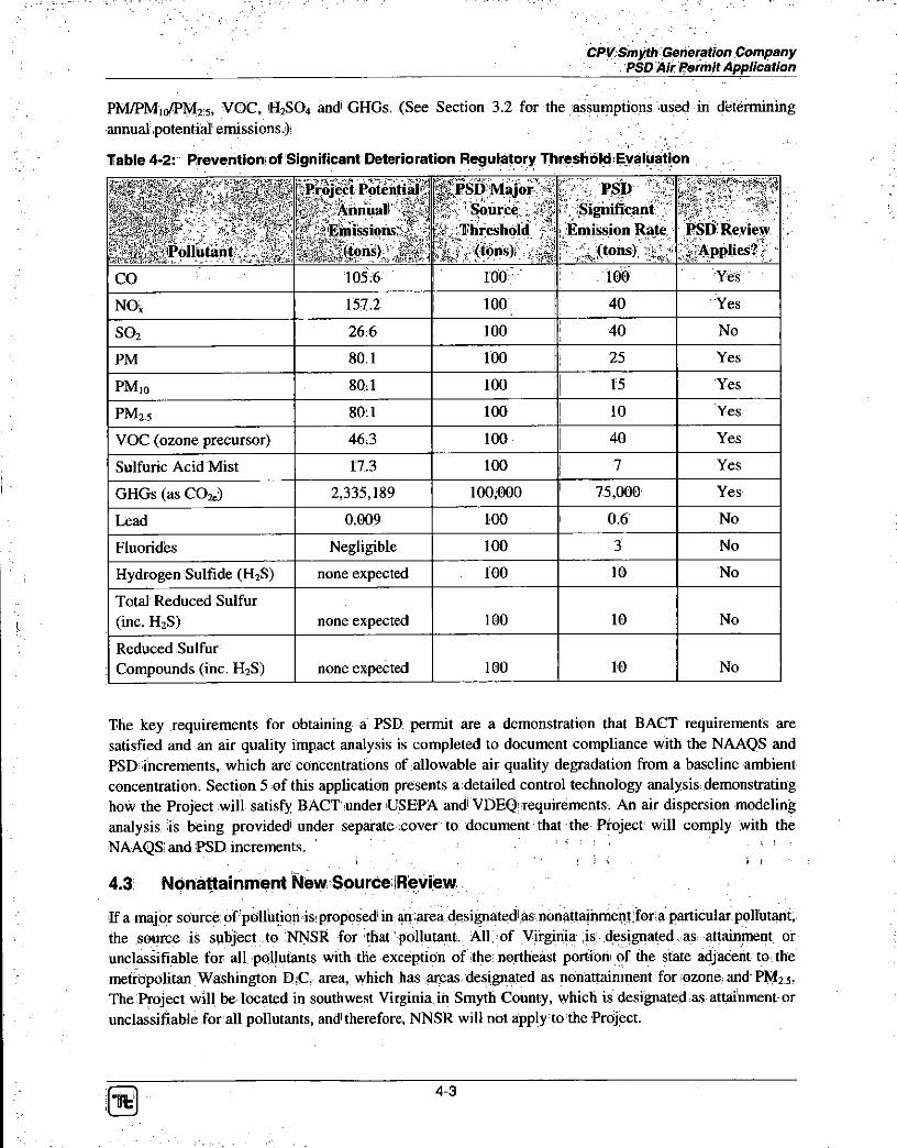
The BACT analysis for' the combustion turbines and duct burners is combined as the duct burners cannot operate without the combustion turbines in operation. Since the combustion turbines can operate with and without duct firing, BACT emission rates: were reviewed for/b Provided in Table 5-1 is a summary of recently permitted emis'sibnilimitsffor- combined jeyc^ projects larger than 100 MW. Table 5-1 provides the perrnitted emission^ for each criteria pollutant from the Project subject to BACT requirements. Permitted BACT GHG emission limits for combined cycle combustion turbine projects are provided' separately in Section 5.2.8. The emission limits provided in Table 5-1 serve as the basis for determining the "most stringent emissions limitation which is achieved in practice" for large combined cycle combustion turbines.
5.2.1 Nitrogen Oxides (NOx)
NOx emissions can be controlled using combustion controls and/or flue gas treatment. For the combustion turbines, available combustion controls include dry low-NOx (DLN) combustors and the most common flue gas treatment is SCR. DLN combustors are designed to minimize the formation of-NO* from fuel combustion while SCR is placed in the combustion turbine exhaust to further reduce emissions. For the duct burners, available combustion controls include low-NOx burners (LNB). An SCR will control NOx
emissions from both the Combustion turbines and duct burners.
An SCR system is composed of an ammonia storage tank, ammonia forwarding pumps and controls, an injection grid (a system of nozzles that spray ammonia into the exhaust gas: ductwork), a catalyst reactor, and instrumentation and controls. The injection grid disperses NH 3 in the flue gas upstream of the catalyst, and NH 3 and NOx are reduced to nitrogen and water by the catalyst. SCR catalysts operate efficiently within a wide range of temperatures. For base metal catalysts typically used on combined cycle combustion turbine projects, the effective operating temperature range is between 450PF and 850°F: Since combined cycle combustion turbine projects employ a HRSG to produce steam from the hot exhaust gases in order to generate additional electricity in a steam turbine, the SCR can be placed within the HRSG under its optimum temperature window to maximize NGX reduction.
Al l of the projects listed in Table 5-1 have been permitted to utilize DLN combustors and SCR to achieve the permitted NOx emission levels. Accordingly, the Project is proposing to use state of the art DLN combustors in combination with SCR to control NOx emissions from the turbines as well as LNB for the duct burners.
Based on a review of recently permitted projects, 210 ippm corrected to 15% 0 2 oht:avlabour ay(eraging; basis was determined to be the most stringent emission limit achieved in practice and is selected as BACT for the Project. Since the top level of control was selected, an evaluation of the economic, energy, and environmental impacts is not necessary. BACT will be demonstrated oh a continuous basis through the application of a CEMS to monitor NOx and 0 2 concentrations and calculate the remission; rate in units of the BACT emission limit.

CPV Smyth Generation Company PSD Air Permit Application
Table 5-1: Summary Of Recent PSD Criteria Pollutant BACT Determinations for Large (>100MW) Gas Fired Combined-Cycle Generating Plants
Facility Location Permit Date Turbine
Emission Limits and Controls
Facility Location Permit Date Turbine
NO/ (ppm)
CO1
(ppm) VOC1
(ppm) PM 1 0/PM 2 . 5
2
(lb/MMBtu) H 2 S0 4
(lb/MMBtu) Green Energy Partners / Stonewall
Leesburg, VA 04/30/2013 GE 7FA 2.0 (w/ and w/o DF3)
LAER
2.0 (w/ and w/o DF)
l .0 (w/o DF) 2.4 (w/ DF)
0.003344
(w/ and w/o DF) N/A
Brunswick County Power Freeman, VA 05/23/2012 Mitsubishi M501 GAC
2.0 (w/ and w/o DF)
1.5 (w/o DF) 2.4 (w/ DF)
0.7 (w/o DF) 1.6 (w/ DF)
0.0033 (w/o DF) 0.0047 (w/ DF)
0.0058 (w/o DF) 0.0067 (w/ DF)
Dominion Warren County Front Royal, VA 12/21/2010 Mitsubishi M501 GAC
2.0 (w/ and w/o DF)
1.5 (w/o DF) 2.4 (w/ DF)
0.7 (w/o DF) 1.6 (w/ DF)
0.0027 (w/o DF) 0.0040 (w/ DF)
0.00013 (w/o DF) 0.00025 (w/ DF)
Carroll County Energy Washington Twp., OH
11/5/2013 GE 7FA 2.0 (w/ and w/o DF)
2.0 (w/ and w/o DF)
1.0 (w/o DF) 2.0 (w/ DF)
0.0108 (w/o DF) 0.0078 (w/DF)
0.0012 (w/o DF) 0.0016 (w/DF)
Renaissance Power Carson City, MI 11/1/2013 Siemens 501 FD2
2.0 (w/ and w/o DF)
2.0 (w/ and w/o DF)
2.0 (w/ and w/o DF)
0.0042 (w/ and w/o DF)
N/A
Langley Gulch Power Payette, ID 08/14/2013 Siemens SGT6-5000F
2.0 (w/ and w/o DF)
2.0 (w/ and w/o DF)
2.0 (w/ and w/o DF)
0.0053 (w/ and w/o DF)
N/A
Kleen Energy Middletown, CT 07/2/2013 Siemens SGT6-5000F
2.0 (w/ and w/o DF)
0.9 (w/o DF) 1.7 (w/ DF)
5.0 (w/ and w/o DF)
0.0051 (w/o DF) 0.0059 (w/ DF)
0.0006 (w/o DF) 0.0007 (w/ DF)
Oregon Clean Energy Oregon, OH 06/18/2013 Siemens SCC6-8000H
2.0 (w/ and w/o DF)
2.0 (w/ and w/o DF)
2.0 (w/ and w/o DF)
0.0047 (w/o DF) 0.0055 (w/ DF)
0.0006 (w/o DF) 0.0007 (w/ DF)
TECO Polk Power 2 Mulberry, FL 05/15/2013 GE 7FA 2.0 (w/ and w/o DF)
4.1 (no ox. cat)
1.4 (no ox. cat)
N/A 2grS/100ft3ofgas
Sunbury Generation Sunbury, PA 04/01/2013 "F Class" 2.0 (w/ and w/o DF)
2.0 (w/ and w/o DF)
1.0 (w/o DF) 3.9 (w/ DF)
0.0088 (w/ and w/o DF)
0.0018
Hess Newark Energy Newark, NJ 11/01/2012 GE7FA.05 2.0 (w/ and w/o DF)
LAER
2.0 (w/ and w/o DF)
1.0 (w/ and w/o DF)
0.00474 (w/o DF) 0.00583 (w/ DF)
0.00008 (w/o DF) 0.0006 (w/ DF)
Moxie Liberty LLC Asylum Twp., PA
10/10/2012 "F Class" 2.0 (w/ and w/o DF)
2.0 (w/ and w/o DF)
1.0 (w/o DF) 1.5 (w/ DF)
0.0057 (w/ and w/o DF)
0.0002
Cricket Valley Energy Center
Middleton, NY 09/27/2012 "F Class) 2.0 (w/ and w/o DF)
LAER
2.0 (w/ and w/o DF)
1.0 (w/o DF) 2.0 (w/ DF)
LAER
0.005 (w/o DF) 0.006 (w/ DF)
N/A
Deer Park Energy Harris, TX 09/26/2012 Siemens West. 501F
2.0 (w/ and w/o DF)
4.0 (w/ and w/o DF)
2.0 (w/ and w/o DF)
0.010 (w/ and w/o DF)
N/A
CPV Smyth Generation Company PSD Air Permit Application
Table 5-1: Summary Of Recent PSD Criteria Pollutant BACT Determinations for Large (>1 OOMW) Gas Fired Combined Cycle Generating Plants
Facility Location Permit Date Turbine
Emission Limits and Controls
Facility Location Permit Date Turbine
NO,1
(ppm) CO1
(ppm) VOC1
(PPm) PM10/PM2/ (lb/MMBtu)
H2SO4 (lb/MMBtu)
ES Joslin Power Calhoun, TX 09/12/2012 GETTFA 2.0 (w/ and w/o DF)
4.0 (w/ and w/o DF)
2.0 (w/ and w/o DF)
0.010 / ' ' (w/ and w/o DF)
N/A ) '
Pioneer Valley Energy Center
Westfield, MA 04-12-2012 Mitsubishi 501G
2.0 (w/ and w/o DF)
LAER
2.0 (w/ and w/o DF)
N/A 0.0040 -(w/ and w/o DF)
N/A
Thomas C. Ferguson Power
Llano, TX 09/01/2011 GE 7FA 2.0 (no DF)
4.0 (no DF)
270 (no DF)
0.018 (no DF)
0.0078
Palmdale Hybrid Power Palmdale, CA 10/18/2011 GE7FA 2.0 (w/ and w/o DF)
2.0 (w/o DF) 3.0 (w/DF)
N/A 0.0048 (w/o DF) 0.0049 (w/ DF)
N/A
A venal Power Center A venal, CA 05/27/2011 GE7FA 2.0 (w/ and w/o DF)
2.0 (w/ and w/o DF)
N/A 11.78 Ib/hr w/DF 8.91 Ib/hr w/oDF
N/A
Portland Gen. Electric Carty Plant
Morrow, OR 12/29/2010 Mitsubishi M501GAC
2.0 ( w/ and w/o DF)
N/A N/A ..0:0025 V (w/ and w/o DF)
N/A
Live Oaks Power Sterling, GA 03/30/2010 Siemens SGT6-5000F
2.5 (no DF)
2.0 (w/o DF) 3.2 (w/DF)
2.0 (no DF)
• N/A' . ' . 0.5 gr S/100ftJ of gas
Victorville 2 Hybrid Victorville, CA 03-11-2010 i
GE7FA 20 (w/ and w/o DF)
2.0 (w/o DF) 3.0 (w/ DF)
N/A 18.0 ib/hr.w/ DF 12.0 lb/hr w/o DF
N/A
High Desert Power : r Victorville, CA 03-11-2010 Siemens West. 501F
2.5 (w/and w/o DF)
4.0 (w/ and w/o DF)
- N/A ' N/A • N/A •
Wolf Hollow Power Hood, TX 03/03/2010 GE 7FA 2.0 (w/ and w/o DF)
10.0 (no ox. cat)
3.0 (no ox. cat)
N/A ; • N/A ; •
Panda Sherman Power Grayson, TX 02/03/2010 GE 7FA 2.0 (w/ and w/o DF)
15.0 (no ox. cat)
4.0 (no ox. cat)
' N/A ' N/A
1 Concentration in ppm is parts per million by volume, dry, at 15 percent 0 2 . 2 Concentration in pounds per million Btu heat input (HHV), except as noted, including front (filterable) and back-half (condensable) PM. 3 DF refers to ductcfiring : .

CPV Smyth Generation Company PSD Air Permit Application
5.2.2 Carbon Monoxide (CO)
CO is emitted from combustion turbines and duct burners as a result of incomplete oxidation of the fuel. CO emissions can be minimized by the use of proper combustor design and good combustion practices. The most stringent CO add-on pollution control technology is an oxidation catalyst, which is a passive reactor that consists of a honeycomb grid of metal panels coated with a platinum catalyst; the catalyst oxidizes the CO to C0 2. For a combined cycle combustion turbine, the oxidation catalyst is placed in the HRSG in front of the SCR catalyst so that it will operate at or above the SCR catalyst temperature.
With a few exceptions, the great majority of projects listed in Table 5-1 have been permitted with an oxidation catalyst to achieve the permitted CO emission levels, including the three most recent projects in Virginia. Accordingly, the Project is proposing to use an oxidation catalyst to control CO emissions from the combustion turbines and duct burners.
A review of recently permitted projects shows that most are permitted at an emission rate at or above 2.0 ppm corrected to 15% 0 2 on a 1-hour averaging basis during all operating periods. A few projects have marginally lower permitted limits without duct firing and one project has a lower limit with duct firing, but these projects have a different combustion turbine than the Alstom GT24 and cannot operate down to the very low minimum operating load of the Alstom GT24 turbine. For these reasons, 2.0 ppm corrected to 15% 0 2 on a 1-hour averaging basis was selected as BACT for all operating cases, consistent with the preponderance of projects listed in Table 5-1. BACT will be demonstrated on a continuous basis through the application of a CEMS to monitor CO and 0 2 concentrations and calculate the emission rate in units of the BACT emission limit.
5.2.3 Volatile Organic Compounds (VOCs)
Similar to CO emissions, VOCs are emitted from combustion turbines as a result of incomplete oxidation of the fuel. VOC emissions from combustion turbines can be minimized by the use of proper combustor design and good combustion practices. Depending upon the species of VOCs in the turbine exhaust, the oxidation catalyst employed to reduce CO emissions may also reduce VOC emissions but the reduction in VOC emissions is expected to be modest. Therefore, the critical control technique for VOC emissions is proper combustor design and good combustion practices.
VOC emissions from duct burners are typically higher than from the combustion turbine. A review of the permitted projects in Table 5-1 shows a range of permitted VOC emission limits, most with an allowable emission rate that is higher during duct firing of the HRSG. The permitted VOC emission limit for any combustion turbine project will be dependent upon the make and model of the combustion turbine selected and the vendor guaranteed emission rate. The combustion turbine selected for the Project is an Alstom GT24, for which there is no comparable project in Table 5-1.
The Alstom GT24 was selected for the Project due to its unique ability to enable the combined cycle power plant to meet its permitted BACT emission rates at LLO, allowing the GT24 unit to cycle up and down and follow the projected demand in the area. Since the turbines can operate at LLO, it will minimize startup and shutdown (SU/SD) operation during which VOC emissions are elevated as compared to steady state operation. For comparison, the combustion turbines permitted in Table 5-1 will typically have a minimum operating load of 50%, below which, they cannot meet their permitted BACT emission rates. As a result, these other turbine models could require a significant amount of SU/SD operation and consequently, increased VOC emissions as a result.
5-6

C^vsrn^^r7erat/^c^pan^ ^ ^ ^S^A/r Pernor App/^at/^n
Based upon Atom's expected VOC en^ssions from me combustion t ^ oxidationcatalyst,meproposedVOCBACTernissionratesare averaging basis without duet firing ductfirmgVT^ Tabie ^ f and' e q n i ^ Therefore^these^iirn
and environmental impacts is not necessary. ^ ^ ^ B
5^4 P a r t ^ U ^ Emissions ofparticulate matterresultfromtracequahti^
ofmcompieteccm^ particuiatematter (PM)emissionsfromtheProjectarepr^^ (PM^^ and, therefore, ermssions of PM, PM^ and PM2^ are presumed! ^ ^ areminin^zedhyutiiizingstateoftheartcomhustion^ Idwestashandsulfurcontentavailable. Areviewoftheperrmttedermssio^^ basis SirmiartoVOCernissions, me permitted PM be dependent upon the make and model of the combustionmrbine selected and the vendor gua ermssion rate, Eorexample, CEguarantees a fiat pound per bourPMer^^ loads for their combustion turbines. This results inawide range PM emission rates onalb/MMBtu basis for CE turbines. AcomparisonoftherecentlyperrmttedCreenEnergyPartnersprojectinVirginia Carroll County project in Ohio showsapermittedPM emission rate difference ofafactor of three(ona lb/MMBtu basis) for the same model CE turbine. Thisdiscrepancy results fromtheCreenEnergy Partners permitted PM emission rate in lb/MMBtu being at full operating load while the Carroll County limit lb/MMBtu is at minimum operating load.
The combustion turbine selected for me Project is an /^stom C T ^ project in Table As discussed in Section 5.2.3, the Alstom CT24 was selected for the Project in part due to its unique abdity to meet its permitted BACT emission rates at very lowoper^^ Due to theuniqueoperation of the AlstomCT24,CPV Smythdoes not believe the Project canbe directly compared:totheprojectslistedinTabie5-iforPM emissions
BACTforPMemissions fromtheProjectareproposedtobegoodcombustionpractices,theuseof naturalgaswithamaximum sulfur contentof0.5gr/100scfandtheguaranteedemission rates from Alstom, Alstom's guaranteed PM'en^ssions ona l ^ and ambient conditions, m order to establis^B^ operatingloadare;proposedfor:thePrbject,inciudm limits are absolute maximum values while tbe lb/MMBm limit represents all scenarios at load, including duct firing. Therefore, higher emissions at reduced operating loads may occur in terms of lb/MMBtu but no increase in mass emissions will result.
^ 12.9 lbs/hr with duct firing;
^ 9.41bs/hr without duct firing; and
^ 0.0051b/MMBtu(atfullload).
57

CPV Smyth Generation Company PSD Air Permit Application
Full operating load limits are proposed to establish BACT since performance emissions testing will be conducted at full operating load and this approach is consistent with the most recent combined cycle generating project permitted in Virginia. The proposed limit on a lb/MMBtu basis is within the range of recently permitted projects in Table 5-1. Further reductions in PM emissions from the turbines are not technically feasible as there are no known combustion turbines equipped with add-on PM pollution controls and the natural gas delivered to the plant will be pipeline quality.
5.2.5 Sulfur Dioxide (S0 2)
S0 2 is emitted from the combustion turbines and duct burners as a result of the oxidation of the sulfur in the fuel. The only practical means for controlling S02 emissions from the combustion turbines and duct burners is to limit the sulfur content of the fuel. The Project proposes to use pipeline quality natural gas as the sole fuel. Pipeline quality natural gas is the lowest sulfur content fuel commercially available and the sulfur content of the natural gas will be no greater than 0.5 gr/100 scf of gas, or approximately 0.0015 lbs SCVMMBtu.
5.2.6 Sulfuric Acid Mist (H 2S0 4)
In any combustion process, the sulfur in the fuel is predominantly oxidized to S0 2 but a small percentage of the sulfur is oxidized to S03, which reacts with moisture in the exhaust to form sulfuric acid (H2S04). Similar to S02 emissions, the top level of control for H 2S0 4 emissions is to limit the sulfur content of the fuel. The Project proposes to use pipeline quality natural gas as the sole fuel, which is the fuel with the lowest sulfur content commercially available and therefore, represents the top level of BACT for the Project.
Alstom provided CPV with guaranteed H 2S0 4 emissions based upon their estimate of sulfur to S0 3
conversion. The maximum H 2S0 4 emission rate shall be no greater than 0.00095 lb/MMBtu, which is consistent with the permitted emission limits for projects listed in Table 5-1.
5.2.7 Ammonia (NH3)
NH 3 is injected into the exhaust of the combustion turbines prior to the SCR to facilitate the conversion of NOx to nitrogen and water. NH 3 is injected at a ratio slightly greater than the amount required to convert 100% of the NOx if the SCR operated at 100% efficiency. Additional NH 3 is required mostly to offset mixing inefficiencies in the exhaust and to some degree to offset insufficient residence time for reaction of the NH3/NOx mixture across the catalyst. Consequently, some of the injected NH 3 does passes through the SCR unreacted and is exhausted to the atmosphere. These NH 3 emissions are called the "ammonia slip." Ammonia slip will be limited to 5.0 ppm corrected to 15% 0 2 during normal operation. Ammonia will not be injected until the SCR catalyst reaches the vendor recommended minimum operating temperature to ensure a high reaction efficiency.
5.2.8 Greenhouse Gases
USEPA issued a 2011 guidance document for completing GHG BACT analyses titled "PSD and Title V Permitting Guidance for Greenhouse Gases". This guidance is in addition to the 1990 USEPA BACT guidance document. Although the 2011 guidance document refers to the same top-down methodology described in the 1990 document, it provides additional clarification and detail with regard to some aspects of the analysis. The following analysis has been conducted in accordance with both the 1990 and 2011 guidance documents.
Tfc 5-8
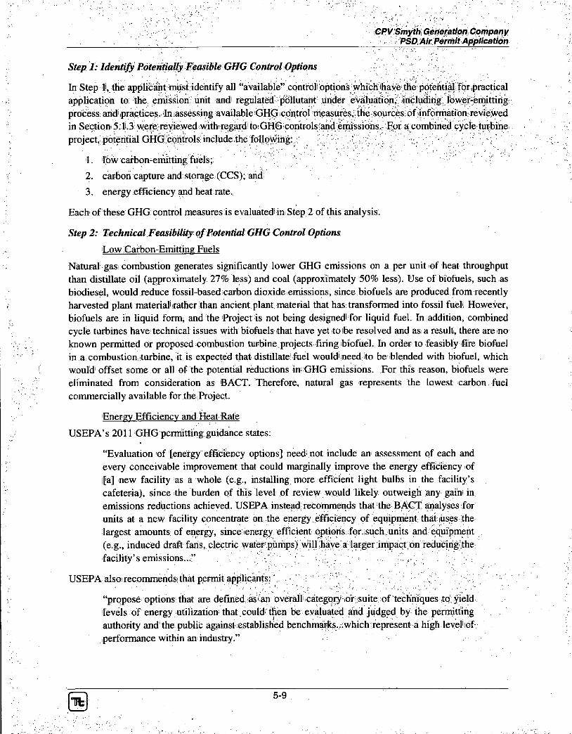
CPV Smyth Generation Company PSD. Air Permit Application
Step 1: Identify Potentially Feasible GHG Control Options
In Step li, the applicant must identify all "available" control options which th application to the. emission unit and regulated pollutant under evaluation, including, lower-emitting process and practices. In assessing available GHG control measures, the sources of information reviewed in Section 5.1.3 were.reviewed with regard to GHG controls and emissions. For a combined cycle turbine project, potential GHG controls include the following: • . v V V. . • . . ' ••; " , , ' . • ;
1. low carbon-emitting fuels;
2. carbon capture and storage (CCS); and!
3. energy efficiency and heat rate.
Each of these GHG: control measures is evaluated' in Step 2 of this analysis.
Step 2: Technical Feasibility qj'Potential GHGControl Options
Low Carbon-Emitting Fuels
Natural gas combustion generates significantly lower GHG emissions on a per unit of heat throughput than distillate oil (approximately 27% less) and coal (approximately 50% less). Use of biofuels, such as biodiesel, would reduce fossil-based carbon dioxide emissions, since biofuels are produced from recently harvested plant material rather than ancient plant material that has transformed into fossil fuel. However, biofuels are in liquid form, and the Project is not being designed for liquid fuel. In addition, combined cycle turbines have technical issues with biofuels that have yet to be resolved and as a result, there are no known permitted or proposed combustion turbine projects firing biofuel. In order to feasibly fire biofuel in a combustion turbine, it is expected that distillate: fuel would need to be blended with biofuel, which would offset some or all of the potential reductions in GHG emissions. For this reason, biofuels were eliminated from consideration as BACT. Therefore, natural gas represents the lowest carbon fuel commercially available for the Project.
Energy Efficiency and Heat Rate
USEPA's 2011 GHG permitting guidance states:
"Evaluation of [energy efficiency options] need not include an assessment of each and every conceivable improvement that could marginally improve the energy efficiency of [a] new facility as a whole (e.g., installing more efficient light bulbs in the facility's cafeteria), since the burden of this level of review would likely outweigh any gain in emissions reductions achieved. USEPA instead recommends that the BACT analyses for units at a new facility concentrate on the energy efficiency of equipment thataises the largest amounts of energy, since energy efficient options for such units and equipment (e.g., induced draft fans, electric water pumps) will have a larger impact,on reducing .the facility's emissions..." .. -; 7 : " " •• V, . ' V -, v • . ; . '
USEPA also recommends that permit applicants: •:' • ..' : v •
"propose options that are defined as an overall category or suite of techniques to yield levels of energy utilization that could then be evaluated and judged by the permitting authority and the public against established benchmarks..:which represent a high level of performance within an industry."
Ufc 5-9

CPV Smyth Generation Company PSD Air Permit Application
With regard to electric generation from combustion sources, the combined-cycle combustion turbine is considered to be the most efficient technology available. GHG emissions from electricity production are primarily a function of the amount of fuel burned. Therefore, a key factor in minimizing GHG emissions is to maximize the efficiency of electricity production, or otherwise known as minimizing the heat rate.
The heat rate of an electric generating unit is the amount of heat needed to generate an amount of electricity and is usually reported in units of Btus of fuel consumed per kilowatt-hour of electricity generated (Btu/kW-hr). An efficient unit will require less fuel to generate a kilowatt-hour of electricity and have a lower heat rate. Most existing fossil-fuel fired generating units are older boilers and turbines that are less efficient than new combined cycle combustion turbine projects. In general, boilers have a higher heat rate than combined cycle combustion turbine projects that use the waste heat from the combustion turbines to generate additional power in a steam turbine. In addition to the efficiency of the electricity generation cycle itself, there are a number of key plant internal energy sinks (parasitic losses) that can improve a plant's net heat rate (efficiency) if reduced.
Measures to increase energy efficiency are technically feasible and are addressed in more detail in Step 4 of this analysis.
Carbon Capture and Storage
USEPA has specifically stated that CCS is technically achievable and must be considered in a GHG PSD BACT analysis. CCS is composed of three main components which are C0 2 capture and/or compression, transport, and storage. CCS may be eliminated from a BACT analysis in Step 2 if it can be shown that there are significant differences pertinent to the successful operation for each of these three main components from what has already been applied to a differing source type. For example, if the temperature, pressure, pollutant concentration, and/or volume of the gas stream to be controlled differ significantly from previous applications, then it is not certain the GHG control device will work in the situation currently undergoing review. Furthermore, CCS may be eliminated from a BACT analysis in Step 2 if the three components working together are deemed technically infeasible for the proposed source, taking into account the integration of the CCS components with the base facility and site-specific considerations (e.g., space for C0 2 capture equipment at an existing facility, right-of-ways to build a pipeline or access to an existing pipeline for transport, access to suitable geologic reservoirs for sequestration or other storage options). While CCS is a promising technology and may be technically achievable for a specific project, USEPA has also stated that at this time CCS will be a technically feasible BACT option in certain limited cases.
As stated in the August 2010 Report ofthe Interagency Task Force on Carbon Capture and Storage, co-chaired by USEPA and the United States Department of Energy, while amine- or ammonia-based C0 2
capture technologies are commercially available, they have been implemented either in non-combustion applications (i.e., separating C0 2 from field natural gas) or on relatively small-scale combustion applications (e.g., slip streams from power plants with exhaust volumes that would correspond to approximately one megawatt of generating capacity). Scaling up these capture processes would represent a very significant technical challenge and potential barrier to widespread commercial deployment in the near term. It is unclear how transferable the experience with natural gas processing is to separation of power plant flue gases, given the significant differences in the chemical make-up of the two gas streams. In addition, integration of these technologies with the power cycle at generating plants present significant cost and operating issues that need to be addressed prior to widespread, cost-effective deployment of C0 2
capture. Current technologies could be used to capture C0 2 from new and existing fossil fuel energy
I t 5-10

CPV Smyth, Generation Company - ._, PSD Air Permit Application
power plants; however, they are not ready for widespread implementation jprimarily because they have not been demonstrated at the scale necessary to establish confidence for power plant applications. To date, United States power generating projects under consideration for using CCS technology have required significant government funding and have been targeted for cpali fired ibpiler ^ exhaust with higher CO2 concentrations and lower ?exnaust volume: as compared to a^combustipn turbine: project. ' C:65::}-y V > ' / 1 - • v •• '•
Regarding pipeline transport for CCS, there does not exist a nearby existing CO2 pipeline infrastructure (see Figure 5-1). The nearest C0 2 pipeline to; the Project is i'm southern Mississippi, :m6re;,than 500 miles from the Project in a straight line distance. The cost to construct a pipeline from the Project to: Mississippi would make the Project uneconomical. Furthermore, the time necessary to acquire all required regulatory approvals and construct the pipeline would take many years.
With regard to storage for CCS, the Interagency Task Force concluded that while there is currently estimated to be a large volume of potential storage sites, "to enable widespread, safe, and'effective CCS, C0 2 storage should continue to be field-demonstrated for a variety of geologic reservoir classes" and that "scale-up from a limited number of demonstration projects to wide scale commercial deployment may necessitate the consideration of basin-scale factors (e.g., brine displacement, overlap of pressure fronts, spatial variation in depositional environments, etc.)."
Based on the abovementioned USEPA guidance regarding technical feasibility, the distance to the nearest C0 2 pipeline and the conclusions of the Interagency Task Force for the C0 2 capture component alone, CCS has been determined to be not technically feasible for the Project.
Step 3: Ranking of Technically Feasible GHGControl Options by Effectiveness
Based on the results of Step 2, the only GHG control option technically feasible for the Project is energy efficiency.
Step 4: Evaluation of Energy Efficiency and Heat Rate
Improvements to: energy efficiency and "heat rate" are important GHG control measures that can be employed to mitigate GHG emissions. The Project is proposing advanced combustion turbine combined cycle technology, which is recognized as the most efficient commercially available technology for producing electric power from fossil fuels. Improvements to the heat rate typically will not change the amount of fuel combusted for a given combustion turbine installation, but it will allow more power to be produced from a given amount of fuel (i.e., improve the heat rate) so that more GHG emissions will be displaced from existing sources.
Key factors addressed in the evaluation of energy efficiency and heat rate are the core efficiency of the selected turbines and the significant factors affecting overalli net heat rateiin combined cycle operating mode. The Project is proposing to install two "F" Class turbines in cpmbined:cycle, configuration. "G" class turbines are slightly more efficient arid thus have a lower heat rate: However, "G" class;:turbines generate approximately 25% more electricity per turbine and would not match the projected! demand for the Project area. In addition, "G" class turbines generally have a higher low operating limit (the lowest MW output at which the facility can operate in compliance with its, permits) than the proposed "F" class turbines. As previously discussed, the capability of the GT24! turbine to operate at LLO is integral to the design of the Project. By matching the projected demand for the area and minimizing startup and shutdown operation, the GT24 turbine provides greater operational flexibility and lower overall emissions. The expected' heat rate differential between "F" and "G" class turbines in combined cycle
m 5-11

CPV Smyth Generation Company PSD Air Permit Application
mode, is expected to be less than 1 percent at ISO conditions, without duct firing. For these reasons, "G" class machines have been eliminated from consideration for the Proposed Project.
r V O \ 1 H 9 f f *
=W^^ -flc-ws
Select CO, Sources and COi Pipelines by Company m
• f t Select CO: Sources
C 0 2 Pipel ines
/ \ / In Service:
• " V Proposed 1
Company
/ S / Anadortio
/ N / * Chaparral Energy
/ V ChovronTozoco
' V Core Energy. LLC
/ \ y Dakota Gasification
/ V penbury Resource*
/ V ExxonMobil
/ S / H e s s .
/ \ / Kinder Morgan
/N/ ' .Occidonta l Petroleum Corp.
/ \ / Oxy Permian
/ S S Penn Won Potroloum
/ V Petro Source
/ \ / Tronspetco
• "V -T r i n i t y COJ
/ A / Wiser .
Figure 5-1 C 0 2 Pipelines in the United States From: "Report of the Interagency Task Force on Carbon Capture and Storage," August,2010, Appendix B.)
The Alstom GT24 combustion turbine, is an advanced generation of "F" class machines that has higher output iand improved; heat rate com represents! the current state-of-the-art for the evolving "F" class technology that: has; been in operation for more than 20 years with thousands of machines in operation. The steam cycle portion of the plant (HRSG; piping and steam turbine generator), designed with a single steam turbine in a "2 on I " configuration will' have: a lower heat rate as compared to a separate steam turbine matched to each combustion mrbine in'a "1 on 1" configuration. ' '
With regard to energy efficiency considerations in combined cycle combustion turbine facilities, the activity with the greatest effect on overall plant efficiency is the method of condenser cooling. As with all steam-based electric generation, combined cycle plants can use either dry cooling or wet cooling for condenser cooling. Dry cooling uses large fans to condense steamsdireetly inside a series of pipes, similar in concept to the radiator of a car. Wet cooling can either be closed cycle evaporative cooling (using
Tfc 5-12

CPV SmythGeneration Company . PSD Air Permit Application
cooling towers), or "once-through" cooling using very large volumes of water: Wet cooling performance is; superior for. efficiency; purposes because of the basic, thermodynamics! of cooling, which ,produces colder water as compared to dry cooling. Additionally, dry cooling requires: more 'electricity than wet cooling and as a result, has a higher parasitic load As a result, operation;of a dry cooling system requires approxi mately .1 -5 % more energy than a wet cooling system (depending on ambient conditions as the difference, between wet and dry systems gets smaller at lower ambient temperatures \
However, there are significant drawbacks to a wet "cooling system: Once-through cooling uses large quantities of water that is returned to the receiving water body at a higher temperature: Wet mechanical draft cooling towers also require a significant quantity of water, mostly due to evaporation to the atmosphere. The evaporative water losses from a wet mechanical draft cooling tower impose an additional burden with the creation of a visible fog plume during certain ambient conditions.
The higher water demand for a wet cooling tower is of significant importance to the Project as the area cannot support higher water usage. For this reason, a dry cooling system with an air cooled condenser was selected for the project as wet cooling was not technically feasible.
Step 5: GHG BACT
The very low heat rates (high efficiency) associated with the combined cycle combustion turbine technology selected for the Project and the use of the lowest carbon fossil fuel, natural gas, as the exclusive fuel, represent GHG BACT for the Project.
A review of recently permitted GHG BACT emission rates was conducted and the results of this review are provided in Table 5-2. The USEPA has also proposed an NSPS standard for GHG emissions from new natural gas fired generating plants of 1,000 lb/MW-hr on a gross output basis.
The emission limits in Table 5-2 and the NSPS are all based upon C02e emissions over a 12-month operating period (except as noted in the table) and, therefore, account for both duct firing and non-duct firing operation. Each limit also takes into account an estimate of performance degradation of the combustion turbines over their expected lifetime. Based upon performance data of the GT24 turbine provided by Alstom and expected operation during duct firing and non-duct firing operation and predicted performance degradation, the GHG BACT emission rate for the Project was determined to be 888 lb/MW-hr on a gross output basis over a 12-month operating period.

CPV Smyth Generation Company PSD Air Permit Application
Table 5-2: Summary Of Recent PSD GHG BACT Determinations for Large (>100MW) Gas Fired Combined-Cycle Generating Plants
Project Location Permit Date
...1 '•• • . -
Combustion Turbine Source C02e Emission Limit
\
Degradation Allowance
Green Energy Partners / Stonewall
; Leesburg, VA
' 04/30/2013 GE 7FA CT - gas firing w/ DF 903 lb/MW-hr (gross) 12.0%
Brunswick County Power
Freeman, VA 05/23/20!2 Mitsubishi M501GAC CT - gas firing w/ DF 920 lb/MW-hr (net) 12.0%
Carroll County Energy
Washington Twp,, OH
11/5/2013 GE7FA CT - gas firingw/DF 859
lb/MW-hr (gross; excluding duct firing) Unknown
Renaissance Power Carson City , MI
11/1/2013 Siemens 501 FD2 CT - gas firing w/ DF . 1,000 lb/MW-hr (gross) Unknown
Oregon Clean Energy Center
Lucas, OH ~ 18-Jun-2013 Mitsubishi M501 or
Siemens SGT-,. 8000H CT -gas firing w/ DF 840 ; lb/MW-hr 12.8%
Calpine Deer Park Deer Park, TX
29-N6v,2012 Siemens 50IF CT - gas firing - 920
lb/MW-hr (30-day rolling) 12.8%
Channel Energy Center
Pasadena, TX 29-N6v-2012 Siemens 50IF CT - gas firing 920
lb/MW-hr (30-day : rolling) 12.8%
Hess Newark Energy Center
Newark, NJ l-Nov-2012 ; GE7FA CT - gas firing w/ DF ,887 lb/MW-hr (gross) 12.8%
Cricket Valley Energy Center
Middletown, : NY
09/27/2012 "F" Class CT - gas firing w/ DF 925 lb/MW-hr (gross) 12.8%
Deer Park Energy Harris, TX 09/26/2012 : Siemens West. : 501F CT - gas firing w/ DF 920 lb/MW-hr (gross) 12.8%
Pioneer Valley Energy Center
Westfield, MA
04-12-2012 . Mitsubishi 501G CT - gas firing w/ DF 895 lb/MW-hr (gross) 8.5%
Thomas C. Ferguson
Horseshoe Bay, TX
lO-Nov-2011 GE7FA CT - gas firing w/ DF. 918 lb/MW-hr (gross) 5%
Palmdale Hybrid Power
Palmdale-CA
10/18/2011 GE 7FA CT - gas firing-w/ DF, & solar thermal 774
lb/MW-hr .(net, including solar) Unknown
f
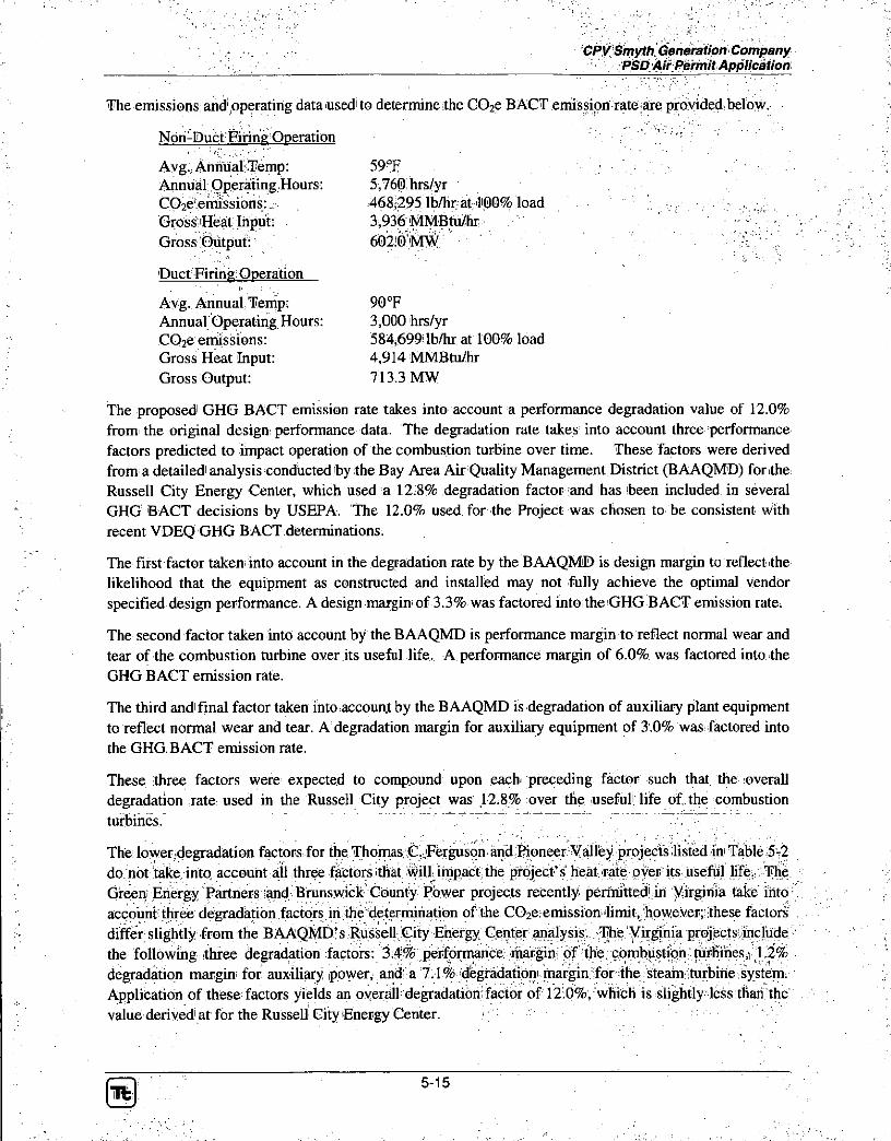
CPV Smyth Generation Company - PSD Air.Permit Application
The emissions; and operating data used' to determine the CC e BACT emission rate iare, provided; below.
Avg. Annual Temp: 59°F Annual Operating Hours: 5,760 hrs/yr COze emissions:. 468,295 lb/hr at 100% load Gross Heat Input: 3,936 MMBtu/hr Gross Output: 602:0 MW
Duct Firing Operation
Avg. Annual Temp: 90°F Annual Operating Hours: 3,000 hrs/yr C02e emissions: 584,699 lb/hr at 100% load Gross Heat Input: 4,914 MMBtu/hr Gross Output: 713.3 MW
The proposed GHG BACT emission rate takes into account a performance degradation value of 12.0% from the original design performance data. The degradation rate takes into account three performance factors predicted to impact operation of the combustion turbine over time. These factors were derived from a detailed analysis conducted by the Bay Area Air Quality Management District (BAAQMD) for the Russell City Energy Center, which used a 12 8% degradation factor and has been included in several GHG BACT decisions by USEPA. The 12.0% used for the Project was chosen to be consistent with recent VDEQ GHG BACT determinations.
The first factor taken into account in the degradation rate by the BAAQMD is design margin to reflect the likelihood that the equipment as constructed and installed may not fully achieve the optimal vendor specified design performance. A design margin of 3.3% was factored into the GHG BACT emission rate.
The second factor taken into account by the BAAQMD is performance margin to reflect normal wear and tear of the combustion turbine over its useful life. A performance margin of 6.0% was factored into the GHG BACT emission rate.
The third and final factor taken into account by the BAAQMD is degradation of auxiliary plant equipment to reflect normal wear and tear. A degradation margin for auxiliary equipment of 3.0% was factored into the GHG; BACT emission rate.
These three factors were expected to compound upon each preceding factor such that the overall degradation rate used in the Russell City project was 12.8% over the useful life of the combustion turbines.
The lower degradation factors for the Thomas C. .Ferguson and.Pioneer Valley projects listed in Table 5-2 do not take into account all three factors that will impact the project's Heat rate over its useful life. The Green Energy Partners and Brunswick County Power projects recently permitted in Virginia take into account three degradation .factors;.in ffie deterrmhation of the CO e emission!'limit,, however;: these factors differ slightly from the BAAQMD's Russell City Energy Center analysis. The Virginia projects include the following three degradation factors: 3.4% performance margin of the combustion turbines, 1.2% degradation margin for auxiliary power, and a 7.1% degradation margin for the steam turbine system. Application of these factors yields an overall degradationrfaeipr of 12.0%, which is slightly less than the value derived at for the Russell City Energy Center.
I t : 5-15
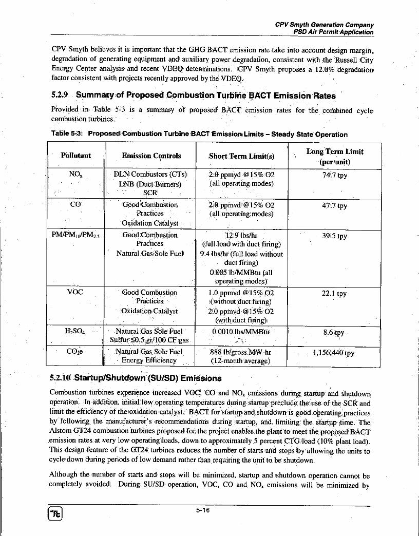
CPV Smyth Generation Company PSD Air Permit Application
CPV Smyth believes it is important that the GHG BACT emission rate take into account design margin, degradation of generating equipment and auxiliary power degradation, consistent with the: Russell City Energy Center analysis and recent VDEQ determinations. CPV Smyth proposes a 12.0% degradation factor consistent with projects recently approved by the VDEQ.
•V '
5.219 Summary of Proposed Combustion Turbine BACT Emission Rates
Provided in Table 5-3 is a summary of proposed BACT emission rates for the combined cycle combustion turbines.
Table 5-3: Proposed Combustion Turbine BACT Emission Limits - Steady State Operation
Pollutant Emission Controls Short Term Limit(s) Long Term Limit
(per-unit)
NO, DLN Combustors (CTs) LNB (Duct Burners)
' SCR
2:0 ppmvd @15%02 (all operating modes)
74.7 tpy
1 • CO ' Good Combustion Practices
Oxidation Catalyst
2:0 ppmvd @ 15% 02 (all! operating: modes)
47.7 tpy
PM/PM|(/PM25 Good Combustion Practices
Natural Gas: Sole Fuel
12.9 lbs/hr . (full load with duct firing)
9.4 lbs/hr (full load without duct firing)
0.005 lb/MMBtu (all operating modes)
39.5 tpy
VOC Good Combustion Practices:
Oxidation Catalyst
1.0 ppmvd @15% 02 (without duct firing)
2.0 ppmvd @15% 02 (with duct firing) ,
22.1 tpy
H2SO„ Natural Gas Sole Fuel Sulfur <0.5 gr/100 CF gas
0.0010 Ibs/MMBtu • Vrv • • [
8.6 tpy
C02e ' Natural Gas Sole Fuel • Energy Efficiency
, 888 lb/gross MW-hr : (12-month average)
1,156,440 tpy
5.2.10 Startup/Shutdown (SU/SD) Emissions
Combustion turbines experience increased VOC, CO and NO* emissions during startup and shutdown operation. In addition, initial: low operating temperatures during startup preclude; the use of the SCR and limit the efficiency ofthe oxidation catalyst: BACT for startup and shutdown is good operating practices by following the manufacturer's recommendations during startup, and limiting the startup time. The Alstom GT24 Combustion turbines proposed for the project enables the plant to meet the proposed BACT emission rates at very low operating loads, down to approximately 5 percent CTG load (10% plant load). This design feature of the GT24 turbines reduces the number of starts and stops iby allowing the units to cycle down during periods of low demand rather than requiring the unit to be shutdown.
Although the number of starts and stops will be minimized, startup and shutdown operation cannot be completely avoided. During SU/SD operation, VOC, CO and NOx emissions will be minimized by
5-16

• v CPV Smyth-Generation Company . PSD Air Permit Application
proper operational practices. The combustion turbines will be operated in,aecordariee witb manufacturer specifications during SU/SD periods to ensure that emissions are minimized during these short periods. Additionally, NH 3 injection will be initiated as a soon as practicable after the SCR catalyst reaches the vendor specified minimum operating temperature to minimize NOx. emissions during these periods. The estimated startup/shutdown emissions for the combustion turbines are provided _ in Table 5-4. Any increase, in emissions during SU/SD operation is included in the potential annual emissions provided in Table 5-3; detailed emission calculations are provided in Appendix B% : V . Vi /
Table 5-4: Transient Emission Limits (lbs per event)
Pollutant Gold Start Warm Start Hot Start Shutdown Transition to and from LLOC
NOx 61 56 50 4.6 2.9
CO 77 71 47 17 32
VOC 73 69 39 25 48
For the purposes of Table 5-4, the following definitions are applied:
• Cold Startup refers to restarts made at least 60 hours or more after shutdown and shall not last longer than 180 minutes per occurrence,
• Warm Startup refers to restarts made between 8 and 60 hours after shutdown and shall not last longer than 126 minutes per occurrence,
• Hot Startup refers to restarts made between 0 and 8 hours after shutdown and shall not last longer than 56 minutes per occurrence,
• Shutdown refers to the period between the time the turbine load drops below 5 percent operating load and the fuel supply to the turbine is: cut. Shutdown operation shall not last longer than 11 minutes per occurrence.
• Transition to and from LLO refers to the period between LLO (5% turbine load) and compliance load and shall not last longer than 24 minutes for ramp down (12 minutes) and ramp up (12 minutes) combined'
5.3 Auxiliary Boiler
The Project will include an auxiliary boiler rated at 93 MMBtu/hr fired solely with natural :gas. The auxiliary boiler will provide steam to warm up the steam turbine to minimize the duration of plant startups. Annual operation of the auxiliary boiler will be limited to a full load equivalent of .4,000 hours per year. Emissions from the boiler are subject to BACT requirements and a review was conducted of recently permitted emission rates from natural gas fired boilers; the results of this: review are provided in Table 5-5. The emission limits provided in Table 5-5 serve as the basis for determining the. "most: stringent emissions limitation which is achieved inipractice" for natural gas fired auxiliary, boilers.
5-17

CPV Smyth Generation Company PSD Air Permit Application
5.3.1 Nitrogen Oxides (NOx)
Similar to the combustion turbines, NOx emissions can be controlled using combustion controls and/or flue gas treatment. For the auxiliary boiler, the most advanced level of control identified in Table 5-5 is ultra LNB. Ultra LNB can achieve a NOx emission rate of 9 ppm corrected to 3% 0 2 . Based upon recently permitted projects; listed in Table 5-5, this is the top level of control for a gas-fired auxiliary boiler rated at less than 100 MMBtu/hr. , . ^
Further reductions in NOx emissions could be achieved through installation of an SCR. However, the installation of an SCR on the auxiliary boiler would not be cost effective due to the already very low NOx emissions from the boiler. Potential NOx emissions from the boiler are only 1.0 lbs/hr and limited to 2.0 tpy due to the proposed operating restriction of 4,000 hrs/yr. The VDEQ's engineering analysis for the recently permitted Brunswick Energy project, showed a cost to control of over $60)000! per ton of NQX
removed for SCR on an auxiliary boiler equipped! With ultra-low -NOx burners. Furthermore, the Green Energy Partners / Stonewall project was recently approved by the VDEQ with ultra-low NOx burners as lowest achievable emission rate (LAER) for the auxiliary boiler.
Based on a review of recently permitted! projects, 9.0 ppm corrected to 3% 0 2 was determined to be the most stringent en^ssipn li auxiliary boiler.
5.3.2 Carbon Monoxide (CO)
CO is emitted from the auxiliary boiler as a result of incomplete oxidation of the fuel. CO emissions can be minimized by the use of proper combustor design and good combustion practices. For the auxibary boiler, the most advanced level of control identified in Table 5-5 is advanced ultra LNB. Ultra LNB can minimize CO emissions and achieve an emission rate of 50 ppm corrected to 3% 0 2 . Based upon recently permitted projects listed in Table 5-5, this is the top level of control for a gas-fired auxiliary boiler rated at less than 100 MMBtu/hr.
Further reductions in CO emissions could be achieved: through installation of an oxidation: catalyst. However the: installation of :an ox to the already lowJCO! emissions: from the boiler. Potential CO emissions from the boiler are only 3.4 lbs/hr and limited to 6.8 tpy due to the proposed operating restriction of 4,000 hrs/yr. The VDEQ's engineering analysis for the recently permitted Brunswick Energy project, showed a cost to control of $10,000 per ton of GO removed for an oxidation! catalyst on an auxiliaryibpiler . equipped y/ith ultra-low NOx burners. Furthermore, the Green Energy Partners / Stonewall project concluded that an oxidation catalyst would not be cost effective on an auxiliary boiler emitting over 12 tpy, nearly double the emissions from the Project's auxiliary boiler.
Based on a review of recently permitted projects, 50 ppm corrected to 3% 0 2 was determined to be the most stringent emission: limit achieved in practice and is selected as BACT for the auxiliary boiler.
I t 5-18

CPV Smyth feneration Project PSD Air Permit Application
Table 5-5: Summary Of Recent PSD Criteria Pollutant BACT Determinations for Natural Gas-Fired Auxiliary Boilers
Facility Location Permit Date Controls
Emission Limits and Controls ;
Facility Location Permit Date Controls
NOV (PPm)
CO1
(PPm) VOC1
(lb/MMBtu) ' PM^PMzs2
^ObMMBtM);
Green Energy Partners / Stonewall
Leesburg, VA 04/30/2013 Ultra LNB 9.0 50 0.002 (LAER) ' 0.002
Brunswick County Power Freeman, VA 05/23/2012 Ultra LNB 9.0 50 0.006 0.0075
Dominion Warren County Front Royal; VA 12/21/2010 Ultra LNB 9.0 50 0.0053 0.005
Carroll County Energy ":. - Washington Twp., OH
11/5/2013 Ultra LNB 16.4 75 0.006 0.008
Renaissance Power,! Carson City, MI 11/1/2013 LNB 30 50 0.005 0.005
Kleen Energy . Middletown, CT 07/2/2013 LNB 37 100 0.004 0.006
Oregon Clean Energy , Oregon, OH 06/18/2013 Ultra LNB 16.4 75 0.006 0.008
Hickory Run Energy,, ( . - North Beaver Twp., PA
04/23/2013 Ultra LNB 9.0 50 N/A 0.005
Sunbury Generation Sunbury. PA 04/01/2013 LNB 30 100 0.005 .0.008
Hess Newark Energy;0 Newark, NJ 11/01/2012 Ultra LNB 9,0 50 0.004 ' 0.005
Cricket Valley Energy . • Center ••;
Middleton, NY • 09/27/2012 Ultra LNB 9.0 50 0.0015 (LAER) T ' : •'•. 0.005
Pioneer Valley Energy Center
Westfield, MA 04-12-2012 LNB 25 50 N/A 0.0048
Palmdale Hybrid Power Palmdale, CA 10/18/2011 Ultra LNB 9.0 50 N/A • v ' 0,008
A venal Power Center Avenal, CA 05/27/2011 Ultra LNB 9.0 50 N/A : . 0.005
Portland Gen Electric Carty Plant '-•./•;
Morrow, OR 12/29/2010 LNB 40 N/A N/A • 0.0025 •
Victorville 2 Hybrid : V •', Victorville, CA 03-11-2010 Ultra LNB 9.0 50 N/A 0,003
1 Concentration in ppm is parts per million by volume, dry, at 3 percent 0 2 . 2 GoncentratiQiTdri!pbuhds_,per million'Btu heat input (HHV), except as noted, including front (filterable) and back-half (condensable) PM.

CPV Smyth Generation Project PSD Air Permit Application
5.3.3 Volatile Organic Compounds (VOCs)
Similar to CO, VOCs are emitted from the auxiliary boiler as a result of incomplete oxidation of the fuel. CO emissions can be minimized by the use of proper combustor design and good combustion practices, For the auxiliary boiler, the most advanced level of control identified in Table 5-5 is advanced ultra LNB. There are. no technically feasible add-on control technologies that can reduce VOC emissions from the auxiliary boiler by significantly measurable amounts.
The lowest permitted VOC emission rates identified in fable 5-5 are for the Green Energy Partners / Stonewall and Cricket Valley Energy projects. However, both of these projects are located in ozone non-attainment areas and were required to meet LAER for VOC emissions. The PSD BACT determinations identified in Table 5-5 are consistently at or close to an emission rate of 0.005 lb/MMBtu. Based upon these recent PSD BACT determinations, 0.005 lb/MMBtu was determined to be BACT for the auxiliary boiler.
5.3.4 Particulate Matter (PM, PM*0/andJ PM* 5)
Emissions of particulate matter result from trace quantities of ash (non-combustibles) in the fuel, products of incomplete combustion and conversion of S02 in the exhaust to condensable salts. Particulate emissions, from a combustion source are minimized by utilizing state of the art combustion technology while firing natural gas since natural gas has the lowest ash and sulfur content available. The permitted PM emission rates identified in Table 5-5 range from 0.002 to 0.008 lb/MMBtu, with most projects at 0.005 lb/MMBtu. The three most recent projects permitted in VA cover the full range of these permitted limits. The reason for the difference in permitted PM emission from the auxiliary boiler is most likely due to differences in vendor specified emission rates.
Based upon recent PSD BACT determinations, 0.005 lb/MMBtu was selected as BACT for the auxiliary boiler.
5.3.5 Sulfur Dioxide (S0 2) and Suifuric Acid Mist (H 2S0 4)
Sulfur dioxide and sulfuric acid mist are emitted from the auxiliary boiler as a result of the oxidation of the sulfur in the fuel. The only practical means for controlling S02 and H 2S0 4 emissions from the auxiliary boiler is: to limit the sulfur content of the fuel. The Project proposes BACT to be the use of pipeline quality natural gas with a sulfur content no greater than 0.5 gr/100 scf of gas, or approximately 0.0014 lbs SG2/MMBtu. ' :
5.3.6 Greenhouse Gases
As discussed in Section 5.2.8, there are three control mechanisms for reducing GHG emissions from combustion processes: (1) low carbon-emitting fuels; (2) carbon capture and storage (CCS); and (3) energy efficiency.
The combined cycle combustion turbines account for 99% of the facility' si GHG emissions. As discussed in Section 5.2.8, CCS is not technically or economically feasible for the GHG emissions from the combustion turbines. Since CCS becomes more feasible at larger scales, it is concluded that it is not feasible for the auxiliary boiler as it is not feasible for the combined cycle combustion turbines.
BACT for the auxiliary boiler is proposed to be firing natural gas as the sole fuel and' efficient boiler design.
5-20

• CPV Smyth Generation Project ,'. .. . ,y: PSD Air Permit Application
5.4 EmergencyiGenerator and Fire Pump Engines
The Project will include an emergency diesel generator engine and a diesel fire pump engine. Both engines will be fired with ULSD fuel. Both engines will be used only during emergency situations, with the exception of periodic maintenance/readiness testing, and will be limited to a maximum of 500 operating hours per rolling 12 month period. • '.;' , ; ' 1 , • ; •
There are no post-combustion controls that have been demonstrated in practice for small', emergency internal combustion engines. In order to satisfy BACT requirements, CPV Smyth proposes that the engines meet NSPS 40 CFR 60 Subpart IIII requirements. Under 40 CFR 60 Subpart M I , the emergency generator engine must meet the Tier 2 standards and the fire pump engine must meet the Tier 3: standards for off-road' diesel engines; under 40 CFR 89. Emissions will be controlled through the use of ULSD, engine design, good combustion practices and limited annual operation. With the exception of emergency situations, the engines will only operate for maintenance and readiness testing purposes; operation for these purposes shall be hmited to 100 hours per year. The specific BACT emission limits for each engine are provided in Table 5-6.
Table 5-6: Emergency Engine Emission Standards
Pollutant
Emergency Generator Tier 2 Standard
(g/kW-hr)
Fire Pump Tier 3 Standard
(g/kW-hr)
NOx 6.41 4.02
CO 3.5 3,5
VOC 1.31 0:52
PM/PM10/PM2.5 0.2 0:2
SO23 N/A N/A 1 Tier 2 standard for NOx and VOC is 6.4 g/kWh, combined: To estimate potential
emissions, assumed NO* emissions equal to mis level and VOC emissions equal to the older Tier 1 limit of 1.3 g/kWh.
2 Tier 3 standard for NOx and VOC is 6.4 g/kWh, combined: To estimate potential emissions assumed NOx emissions equal to this level and VOC emissions equal to 0.5 g/kWh.
3 S02 emissions will be limited based upon a maximum fuel sulfur content of 15 ppm (0.0015 lb/MMBtu).
5.5 Fugitive GHG Emission Sources
The project will include natural gas handling-systems and-sulfur 'hexafluofide^(SF6)Lcontainihg circuit breakers. Fugitive losses of natural gas and SF6 will contribute to GHG emissions from the Project. At thisi time; the CPV Smyth does not have the design details necessary (i.e., number of natural gas pipeline connections and circuit breaker SF6 capacity) to quantify fugitive C02e. emissions from, this equipment. Although fugitive CG2e emissions cannot be quantified at this time, the project will implement current BACT standards for these emission sources, including the following:
• The facility will implement an auditory/visual/olfactory leak detection program for the natural gas piping components and make daily observations.
• The facility will equip the circuit breaker with a low pressure alarm and low pressure lockout. SF6
emissions from the circuit breaker willi be calculated annually (calendar year) in accordance with
5-21

CPV Smyth Generation Project PSD Air Permit Application
the mass balance approach in Equation DD-1 of 40 CFR Part 98, Subpart DD. The maximum annual leakage rate for SF6 will not exceed 1 % of the total SF6 storage capacity of the plant's circuit breakers.
» The facility shall maintain records of all measurements and reports related to the fugitive emission sources including those related to maintenance as well as compliance with the Monitoring and QA/QC defined under 40 CFR 98.304 Subpart DD.
Tt 5-22

CPV Smyth Generation Project • PSD Air Permit Application
J:^^#^P%NO##:: '
Appl noation'Forms.
%

DOCUMENT CERTIFICATION
Facility Name: CPV Smyth Generation Company, LLC
Registration No.
Facility Location: Atkins, VA
Type of Submittal Attached: Major NSR Air Permit Application
Certification: I certify under penalty of law that this document and all attachments were prepared under my direction or supervision in accordance with a system designed to assure that qualified personnel properly gather and evaluate the information submitted. Based on my inquiry of the person or persons who manage the system, or those persons directly responsible for gathering and evaluating the information, the information submitted is, to the best of my knowledge and belief, true, accurate, and complete. I am aware that there are significant penalties for submitting false information, including the possibility of fine and imprisonment for knowing violations:
Name of Responsible Official (Print): Peter Podurgiel
Title: Sr. Vice President
Signature:
Form 7-Apri l 8. 2013 Page 1

VIRGINIA DEPARTMENT OF ENVIRONMENTAL QUALITY - AIR PERMITS LOCAL GOVERNING BODY CERTIFICATION FORM
Facility Name: CPV Smyth Generation Company Registration Number:
Applicant's Name: CPV Smyth Generation Company, LLC Name of Contact Person at the site: Gener Gotiangco
Applicant's Mailing address: 8403 Colesville Road Suite 915 Silver Spring, MD 20910
Contact Person Telephone Number: (240) 723-2307
Facility location (also attach map): The proposed Project will be constructed on a 108 acre parcel at a greenfield location in Atkins, VA. Facility site is located in east-central Smyth County, 4 miles east-northeast of Marion, VA, approximately 0.5 miles south of Interstate 81.
Facility type, and list of activities to be conducted: 700 MW combined-cycle natural gas-fired power generating facility with two combustion turbines and associated duct burners. The facility will run as a base load plant with both combustion turbines operating concurrently but the facility will have the capability of operating with a single combustion turbine. Additional plant equipment will include an auxiliary boiler, emergency generator engine, emergency fire pump engine, aqueous ammonia storage tank; air cooled condenser; and various electrical transmission and switching equipment.
The applicant is in the process of completing an application for an air pollution control permit from the Virginia Department of Environmental Quality. In accordance with § 10.1-1321.1. Title 10.1, Code of Virginia (1950), as amended, before such a permit application can be considered complete, the applicant must obtain a certification from the governing body of the county, city or town in which the facility is to be located that the location and operation of the facility are consistent with all applicable ordinances adopted pursuant to Chapter 22 (§§ 15.2-2200 et sea.) of Title 15.2. The undersigned requests that an authorized representative ofthe local governing body sign the certification below.
Applicant's signature:
Date:
The undersigned local government representative certifies to the consistency ofthe proposed location and operation ofthe facility described above with all applicable local ordinances adopted pursuant to Chapter 22 (§§15.2-2200 et seq.) of Title 15.2. of the Code of Virginia (1950) as amended, as follows:
(Check one block)
1 1 The proposed facility is fully consistent with all applicable local ordinances.
1 I The proposed facility is inconsistent with applicable local ordinances; see attached information.
Signature of authorized local government representative:
Date:
Type or print name:
Title:
County, city or town:
[THE LOCAL GOVERNMENT REPRESENTATIVE SHOULD FORWARD THE SIGNED CERTIF ICAT ION T O T H E A P P R O P R I A T E D E Q REGIONAL OFFICE A N D S E N D A C O P Y T O T H E APPLICANT:]
Form 7-Apri l 8, 2013 Page 2

VIRGINIA DEPARTMENT OF ENVIRONMENTAL QUALITY - AIR PERMITS LOCAL GOVERNING BODY CERTIFICATION FORM
Facility Name: CPV Smyth Generation Company Registration Number:
Applicant's.Name: CPV Smyth Generation Company, LLC Name of Contact Person at the site: Gener Gotiangco
Applicant's Mailing address: 8403 Colesville Road Suite 915 Silver Spring, MD 20910
Contact Person Telephone Number: (240)723-2307
Facility location (also attach map): The proposed Project will be constructed on a 108 acre parcel at a greenfield location in Atkins, VA. Facility site is located in east-central Smyth County, 4 miles east-northeast of Marion, VA, approximately 0.5 miles south of Interstate 81.
Facility type, and list of activities to be conducted: 700 MW combined-cycle natural gas-fired power generating facility with two combustion turbines and associated duct burners. The facility will run as a base load plant with both combustion turbines operating concurrently but the facility will have the capability of operating with a single combustion turbine. Additional plant equipment will include an auxiliary boiler, emergency generator engine, emergency fire pump engine, aqueous ammonia storage tank; air cooled condenser; and various electrical transmission and switching equipment.
The applicant is in the process of completing an application for an air pollution control permit from the Virginia Department of Environmental Quality. I n accordance with § 10.1-1321.1. Title 10.1, Code of Virginia (1950), as amended, before such a permit application can be considered complete, the applicant must obtain a certification from the governing body of the county, city or town in which the facility is to be located that the location and operation of the facility are consistent with all applicable ordinances adopted pursuant to Chapter 22 (§§ 15.2-2200 et seq.) of Title 15.2. The undersigned requests that an authorized representative ofthe local governing body sign the certification below.
Applicant's signature:
Date:
The undersigned local government representative certifies to the consistency of the proposed location and operation of the facility described above with all applicable local ordinances adopted pursuant to Chapter 22 (§§15.2-2200 et seq.) of Title 15.2. ofthe Code of Virginia (1950) as amended, as follows:
(Check one block)
l ^ f l h e proposed facility is fully consistent with all applicable local ordinances.
I I The proposed facility is inconsistent with applicable local ordinances; see attached information.
Signature of authorized local government representative:
faftfc/JL* Date:
Type or print name: / ^ / %
T,tteBuM«r 4 fat*} County, city or town: ^&Ky~ffi (C^vdj
[THE LOCAL GOVERNMENT REPRESENTATIVE SHOULD FORWARD THE SIGNED CERTIFICATION TO THE APPROPRIATE DEQ REGIONAL OFFICE AND SEND A COPY TO THE APPLICANT.]
Form 7 - April 8, 2013 Page 2
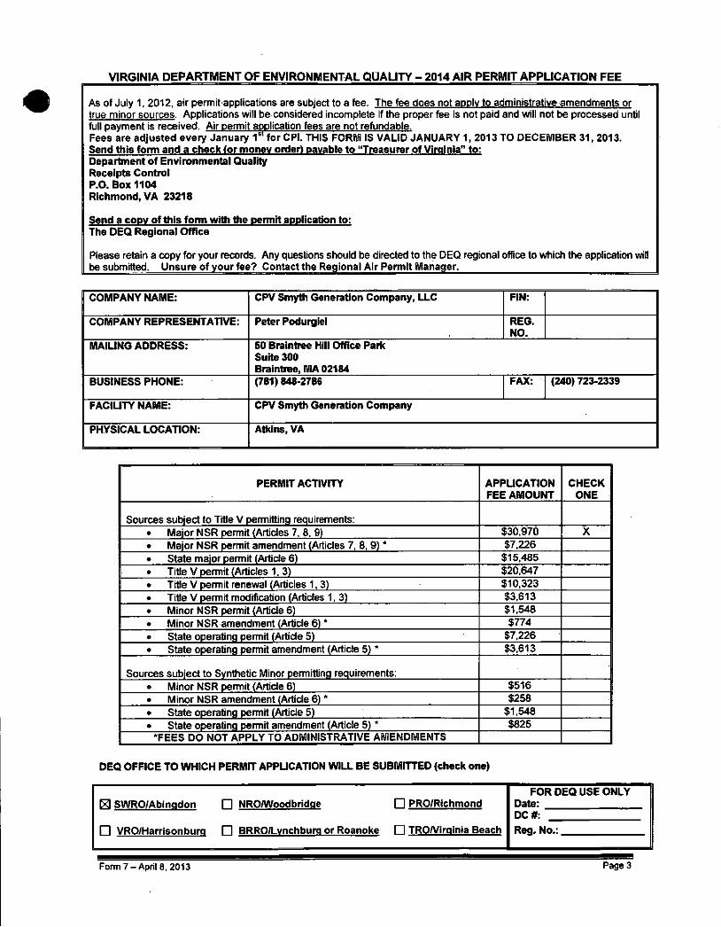
VIRGINIA DEPARTMENT OF ENVIRONMENTAL QUALITY - 2014 AIR PERMIT APPLICATION FEE
As of July 1, 2012, air permit applications are subject to a fee. The fee does not apply to administrative amendments or true minor sources. Applications will be considered incomplete if the proper fee is not paid and will not be processed until full payment is received. Air permit application fees are not refundable. Fees are adjusted every January 1 s l for CPI. THIS FORM IS VALID JANUARY 1, 2013 TO DECEMBER 31, 2013. Send this form and a check (or money order) payable to "Treasurer of Virginia" to: Department of Environmental Quality Receipts Control P.O. Box 1104 Richmond, VA 23218
Send a copy of this form with the permit application to: The DEQ Regional Office
Please retain a copy for your records. Any questions should be directed to the DEQ regional office to which the application will be submitted. Unsure of your fee? Contact the Regional Air Permit Manager.
COMPANY NAME: CPV Smyth Generation Company, LLC FIN:
1 COMPANY REPRESENTATIVE: Peter Podurgiel REG. NO.
MAILING ADDRESS: 50 Braintree Hill Office Park Suite 300 Braintree, MA 02184
BUSINESS PHONE: (781) 848-2786 FAX: (240) 723-2339
FACILITY NAME: CPV Smyth Generation Company
PHYSICAL LOCATION: Atkins, VA
PERMIT ACTIVITY APPLICATION FEE AMOUNT
CHECK ONE
Sources subject to Title V permitting requirements: • Major NSR permit (Articles 7, 8, 9) $30,970 X • Major NSR permit amendment (Articles 7, 8, 9) * $7,226 • State major permit (Article 6) $15,485 o Title V permit (Articles 1, 3) $20,647 • Title V permit renewal (Articles 1,3) $10,323 • Title V permit modification (Articles 1, 3) $3,613 • Minor NSR permit (Article 6) $1,548 • Minor NSR amendment (Article 6) * $774 • State operating permit (Article 5) $7,226 • State operating permit amendment (Article 5) * $3,613
Sources subject to Synthetic Minor permitting requirements: • Minor NSR permit (Article 6) $516 • Minor NSR amendment (Article 6) * $258 • State operating permit (Article 5) $1,548 • State operating permit amendment (Article 5) * $825
'FEES DO NOT APPLY TO ADMINISTRATIVE AMENDMENTS
DEQ OFFICE TO WHICH PERMIT APPLICATION WILL BE SUBMITTED (check one)
El SWRO/Abinqdon F l NRO/Woodbridqe F l PRO/Richmond FOR DEQ USE ONLY
Date:
• VRO/Harrisonbura F l BRRO/Lvnchburq or Roanoke F l TRO/Virainia Beach
DC#:
Rea. No.:
Form 7-April 8, 2013 Page 3

Commonwealth of Virginia Department of Environmental Quality
#
AIR PERMIT APPLICATION CHECK ALL PAGES ATTACHED AND LIST ALL ATTACHED DOCUMENTS
Local Government Certification Form, Page 2 Application Fee Form, Pages 3 Document Certification Form, Page 1 General Information, Pages 5-6 Fuel Burning Equipment, Page 7 Stationary Internal Combustion Engines, Page 8 Incinerators, Processing, Inks, Coatings, Stains, and Adhesives, VOC/Petroleum Storage Tanks, Pages Loading Rack and Oil-Water Separators, Fumigation Operations, Air Pollution Control and Monitoring Equipment, Page 9 Air Pollution Control/Supplemental Information, Page 10 Stack Parameters and Fuel Data, Page 11 Proposed Permit Limits for Criteria Pollutants, Page 12 Proposed Permit Limits for Toxic Pollutants/HAPs, Page 13 Proposed Permit Limits for Other Reg. Pollutants, Page 14 Proposed Permit Limits for GHGs on Mass Basis, Page 15
1 Proposed Permit Limits for GHGs on C0 2e Basis, Page 16 BAE for Criteria Pollutants, Page 27 BAE for GHGs on Mass Basis, Page 28 BAE for GHGs on C0 2e Basis, Page 29
1 Operating Periods, Page 30
ATTACHED DOCUMENTS: 1 Map of Site Location 1 Facility Site Plan
Process Flow Diagram/Schematic MSDS or CPDS Sheets
8 Estimated Emission Calculations Stack Tests Air Modeling Data Confidential Information (see Instructions)
1 BACT Analysis (see Section 5)
Check added form sheets above; also indicate the number of copies of each form in blank provided.
DOCUMENT CERTIFICATION FORM
/ certify under penalty of law that this document and all attachments [as noted above] were prepared under my direction or supervision in accordance with a system designed to assure that qualified personnel properly gather and evaluate the information submitted. Based on my inquiry of the person or persons who manage the system, or those persons directly responsible for gathering and evaluating the information, the information submitted is, to the best of my knowledge and belief, true, accurate, and complete. I am aware that there are significant penalties for submitting false information, including the possibility of fine and imprisonment for knowing violations.
I certify that I understand that the existence of a permit under [Article 6 of the Regulations] does not shield the source from potential enforcement of any regulation ofthe board governing the major NSR program and does not relieve the source ofthe responsibility to comply with any applicable provision ofthe major NSR regulations.
SIGNATURE:
NAME:
TITLE:
PHONE:
EMAIL:
Peter Podurgiel
DATE:
REGISTRATION NO:
1-80-1+
Sr. Vice President COMPANY: CPV Smyth Generation Company, LLC
(781)848-2786 ADDRESS: 50 Braintree Hill Office Park, Suite 300
[email protected] Braintree, MA 02184
References: Virginia Regulations for the Control and Abatement of Air Pollution (Regulations). 9 VAC 5-20-230B and 9 VAC 5-80-1140E.
Form 7-April 8, 2013 Page 4

GENERAL INFORMATION
Person'Completing Form: Steven Babcock Date: 01/27/2014
Registration Number:
Company and Division Name: Tetra Tech FIN: 95-4148514
Mailing Address: 160 Federal St., 3 m Floor Boston, MA 02110
Exact Source Location - Include Name of City (County) and! Fulli Street Address or Directions: Atkins, VA
'< Telephone Number: No. of Employees: Property Area at Site:
Persom to Contact on Air Pollution Matters - Name and Title: Gener Gotiangco Vice President
Phone Number: (240) 723-2307 Fax: (240) 723-2339
Email: GGotiangco(3)cpv.com Latitude and Longitude Coordinates OR UTM Coordinates of Facility:
Reason(s) for Submission (Check all that apply)
| | State Operating Permit This permit is applied for pursuant to provisions of the Virginia Administrative Code, 9 VAC 5 Chapter 80, Article 5 (SOP)
[~Xl New Source
| |: Modification of a Source
| | Relocation of a Source
| |j Amendment to a Permit Dated:
This permit is applied for pursuant to the following provisions ofthe Virginia Administrative Code:
9 VAC 5 Chapter 80, Article 6 (Minor Sources) 9 VAC 5 Chapter 80, Article 8 (PSD Major Sources) 9 VAC 5 Chapter 80, Article 9 (Non-Attainment Major Sources)
X
Permit Type: Q SOP (Art. 5) Q NSR (Art. 6, 8, 9)
Amendment Type: Administrative Amendment Minor Amendment Significant Amendment
This amendment is requested pursuant to the provisions of: ' 9 VAC 5-80-970 (Art. 5 Adm.)
9 VAC 5-80-980 (Art. 5 Minor) 9 VAC 5-80-990 (Art: 5 Sig.)
9 VAC 5-80-1935 (Art. 8 Adm.) 9 VAC 5-80-1945 (Art: 8 Minor) 9 VAC 5-80-1955 (Art. 8 Sig.)
9 VAC 5-80-1270 (Art. 6 Adm.) 9 VAC 5-80-1280 (Art. 6 Minor) 9 VAC 5-80-1290 (Art. 6 Sig.)
9 VAC 5-80-2210 (Art. 9 Adm.) 9 VAC 5-80-2220 (Art. 9 Minor) 9 VAC 5-80-2230 (Art. 9Sig:)
Other (specify):
Explanation of Permit Request (attach documents if needed):
Application.for a proposed combined cycle electric generating ifaciIityirequired to obtain a Maj#NSR;Air Permit subject to Prevention of Significant Deterioration requirements. This document contains a detailed description of the project and potential emission estimates for all pollutants.
Form 7 - April 8, 2013

GENERAL INFORMATION (CONTINUED)
For Portable Plants: NOT APPLICABLE
Is this facility designed to be portable? [~~| Yes [~X] No
• If yes, is this;f acility ialready ipermitted as a portable iplant? \~\ Yes |T7|i No Permit Date:
If not permitted, is this an application to be permitted as a portable plant? . [ | Yes I I No ; -
If permitted as a portable facility, is this a notification of relocation? [~] Yes . | | No
• Describe the new location or address (include a site map):
• Will the portable facility be co-located with another source? Yes \ ^ \ No Reg. No.
Yes • No
Yes • No
Yes • No
Describe the products manufactured and/or services performed at this facility:
A proposed 714 MW combined-cycle natural gas-fired power generating! facility with two combustion turbines and associated duct burners. The facility will run as a base load plant with both combustion turbines operating concurrently but the facility, will have the capability of operating with a single combustion turbine. Additional plant equipment will include an auxiliary boiler, emergency generator engine, emergency fire pump engine, aqueous ammonia storage tank; air cooled condenser; and various electrical transmission and switching equipment.
List the Standard Industrial Classification (SIC) Code(s) for the facility:
4 1 9 ll ; 1
List the North American Industry Classification System (NAICS) Code(s) for the facility:
2 2 1 1 1 i 2
List all the facilities in Virginia under common ownership or control by the owner of this facility:
Not Applicable
Milestones: This section is to be completed if t modification .to existing operations.
ie permit application inclu ' • •' L • •-' '•?""' •'•
des a new emissions unit or
Milestones": . 1 Starting Date: Estimated Completion Date: New Equipment Installation ,! January 2015 > - April 2016 :f /<-> • •'. SMbdificatibn of Existing Process or Equipment •] 1 ' \: ' • " " ' : Start-up Dates 1 May 2017 " ;,
: ' •• • • • ••• *For new or modified installations to be constructed in phased schedule, give cbnstructidn/ipstallatiphi starting and completion date for each phase.
iForm 7 - ' Apnl!8, 2013 Page 6

FUEL BURNING EQUIPMENT: (Boilers, Turbines, Kilns, and Other External Combustion Units)
Company Name: CPV Smyth Generation Company, LLC Date: 01/27/2014 Registration Number:
Unit Ref. No.
Equipment Manufacturer, Type, and Model Number
Date of Manuf.
Date of Const; ,
Max. Rated Input . Heat Capacity
For Each Fuel (Million Btu/hr)
Type of Fuel
Type of Equip. (use;-
Code A) :
Usage (use Code
B)
Requested Throughput*
. (hrs/yr OR fuel/yr) Federal Regulations
that Apply
CT1 Alstom GT24 Combustion Turbine #1 2,270 @ -10°F Natural Gas 19 6 8,760 hrs/yr 40 CFR 60 Subpart
KKKK
CT2 Alstom GT24 Combustion Turbine #2 2,270 @ -10°F Natural Gas 19 6 8,760 hrs/yr 40 CFR 60 Subpart
KKKK
DB1 Duct Burner #1 (Vogt or equivalent) 431 Natural Gas 12 6 1,259 MMCF/yr
of natural gas 40 CFR 60 Subpart
KKKK
DB2 Duct Burner #2 (Vogt or equivalent) .-' 431 Natural Gas 12 6 1,259 MMCF/yr
of natural gas 40 CFR 60 Subpart
KKKK
AB CB Nebraska Model NB-300D-70 Auxiliary Boiler (or equivalent) 92.4 Natural Gas 12 4 359.5 MMCF/yr
of natural gas 40 CFR 60 Subpart Dc
40 CFR 63 Subpart JJJJJJ
I X | Estimated Emission Calculations Attached (include references of emission factors) and/or Stack Test Results if Available
Code A - Equipment - ' - - Code B - Usage
BOILER TYPE: 1. Pulverized Coal - Wet Bottom 2. Pulverized Coal - Dry Bottom 3. Pulverized Coal - Cyclone Furnace 4. Circulating Fluidized Bed
11. Gas, Tangentially Fired 12. Gas, Horizontally Fired 13; Wood with Flyash Reinjection 14. Vyopd without Flyash Reinjection 15: Qther (specify). Natural Gas Heater
1. Steam Production 2/Drying/Curing 3. Space Heating 4. Process Heat 5. Food Processing 6. Electrical Generation 7. Mechanical Work
5. Spreader Stoke 6. Chain or Travelling Grate Stoker OTHER COMBUSTION UNITS:
1. Steam Production 2/Drying/Curing 3. Space Heating 4. Process Heat 5. Food Processing 6. Electrical Generation 7. Mechanical Work
7. Underfeed Stoker 8. Hand Fired Coal 9. Oil, Tangentially Fired 10. Oil, Horizontally Fired (except rbtarycup)
16. Oven/Kiln ' 17. Rotary Kiln 18. Process Furnace 19. Other (specify) Combustion Turbine
. 8. Other (specify)
"Pick only one option for a requested throughput.
Form 7 - > " 2013 Page 7

STATIONARY INTERNALCOMBUSTION ENGINES:
Company Name: CPV Smyth Generation Company, LLC Date: 01/27/2014 Registration Number:
Unit Ref. No.
Equipment Manufacturer, Type, and Model Number
Date of Manuf.
Date of Const.
Output Brake
Horsepower (bhp)
Output Electrical
Power (kW)
Type of Fuel
Usage* (use
Code C)
Requested Throughput" >
(hrs/yr OR fuel/yr)}
Federal Regulations that:
EG Emergency diesel fired generator engine. Make & model TBD N/A 1,500
Diesel (15 ppmw S)
1 500 hrs/yr 40 CFR 60 Subpart Mil; V
40 CFR 63 Subpart ZZZZ
FP Emergency diesel fired fire pump engine" Make & model TBD 315 N/A Diesel
(15 ppmw S) 1 500 hrs/yr 40 CFR 60 Subpart llll
40 CFR 63 Subpart 7777
. \.' • r • : Available
emission
Code C - Usage
1. Emergency Generator 2. Participates in Emergency Load Response Program 3. Non-Emergency Generator 4. Participates in Demand Response Program(s) 5. Other (specify)
"Can pick more than one option (i.e. 1 and 2 OR 3 and 4)
*Pick on ly one opt ion for a reiquested throughput .
Form 7-Apr i l 8, 2013.

AIR POLLUTION CONTROL AND MONITORING EQUIPMENT:
Company Name: CPV Smyth Generation Company, LLC Date: 01/27/2014 Registration Number:
Air Pollution Control Equipment Monitoring Instrumentation
Unit Ref No.
Vent/ Stack No.
Device Ref. No.
Pollutant/Parameter Manufacturer and Model No.
Type (use
Code N)
Percent Efficiency (%) ',
Specify Type, Measured Pollutant, and Recorder Used
CT1 & DB1 1 SCRi NOx TBD 16 90 40 CFR 75 Compliant CEMS & DAHS for NO, & 0 2
CT1 & DB1 2 OC1 CO TBD 11 . 90 • "\ 40 CFR 60 Compliant CEMS & DAHS for CO
CT2& DB2 1 SCR2 NOx > .:• - TBD 16 90 40 CFR 75 Compliant CEMS & DAHS for NO, & 0 2
CT2& . DB2 2 OC2 CO TBD 11 90 40 CFR 60 Compliant CEMS & DAHS for CO
I I Manufacturer Specifications Included (To be provided once vendor is selected)
Code N - Type of Air Pol lut ion Contro l Equipment :
1. Settling Chamber a. Hot side 17. Absorber 2. Cyclone b. Cold side a: Packed tower 3. Multicyclone c. High voltage b. Spray tower 4. Cyclone scrubber d. Low voltage c. fray tower 5. Orifice scrubber e. Single stage d, Venturi 6. Mechanical scrubber f. Two stage e. Other: 7. Venturi scrubber a. Other: • r 18. Adsorber
a. Fixed throat 11. Catalytic Afterburner a. Activated carbon b. Variable throat 12! Direct Flame Afteiturner b. Molecular sieve
8. Mist eliminator 13, Diesel Oxidation Catalyst (DOC) c. Activated alumina 9. Filter 14: thermal Oxidizer d. Silica gel
a. Baghouse 15: .Regenerative Thermal Oxidizer (RTO) e. Other: _ b. Other: , 16. Selective Catalytic Reductiori'(SCR)
Selective Non-Catalytic Reduction (SNCR) 19. Condenser (specify) .
10. Electrostatic Precipitator 17. Selective Catalytic Reductiori'(SCR) Selective Non-Catalytic Reduction (SNCR) 20. Other:
Form 7 - r . 2013 Page 9

AIR POLLUTION CONTROL EQUIPIUIENT, SUPPLEMENTAL INFORM
Company Name: CPV Smyth Generation Company, LLC Date: 01/27/2014 Registration Number:
Device Ref. No.
Type (use Code
N)
Liquid Flow Rate (gpm)
(4,5,6,7, 17.19)
Medium
(4,5,6, 7,17,19)
Cleaning Method
(9,10,17, 18)
Number of Fields
J1P1
Number of
Sections
(9,10)
Air to Cloth Ratio (fpm)
(9)
Filter Material
J?L
Inlet Temp.
(°F)
Regeneration Method &
Cycle Time (sec) (18)
Chamber
(°F) -(11,12, 14,15)
Retehtioh Time ^ (sec) '
(11; 12, 14,15)
Pressure
(inch H 20) (3, 4,5, 6, 7,9,17)
SCR1
OC1
SCR2
0C2
16
11
16
11
N/A
N/A
N/A
N/A
N/A
N/A
N/A
N/A
N/A
N/A
N/A
N/A
N/A
N/A
N/A
N/A
N/A
N/A
N/A
N/A
N/A
N/A
N/A
N/A
N/A
N/A
N/A
N/A
650*
650*
650*
650*
N/A
N/A
N/A
N/A
650*
650*
650*
650*
TBD
TBD
TBD
TBD
TBD
TBD
TBD
TBD
NOTE: Numbers l isted in parenthesis in the co lumns above represent the Control Equipment in Code N below.
Code N T y p e of Air Pol lut ion Control Equipment
1. 2. 3: 4. 5. 6. 7:
Settlingi.GfJarrjbgr Cyclone . ; ,
'M0Lcy£lone • Cyclone scrubber Orificescrubber : 'MecKanicaL Verituri s C n j b b e r , , a. Fixed throat b. Variable throat Mist eliminator Filter '-a. Baghouse b. Other:
10. Electrostatic Precipitator
a. Hot side b. Cold side c. High voltage d. Low voltage e. Single stage f. Two stage g. Other:.
13 14
17
11. Catalytic Afterburner 12. Direct Flame Afterburner
Diesel Oxidation Catalyst (DOC) Thermal Oxidizer
15. Regenerative Thermal Oxidizer (RTO) 16. Selective Catalytic Reduction (SCR)
Selective Non-Catalytic Reduction (SNCR)
17. Absorber j a. Packed tower b. Spray tower c. Tray tower d. Venturi j e. Other:
18. Adsorber j a. Activated carbon b. MoleGuj^ c. Activated alumina d. Silica gel e. Other:
'('-.
19. Condenser (specify) 20. Other:
iForrn 7 - April 8,;201.3 Page 10
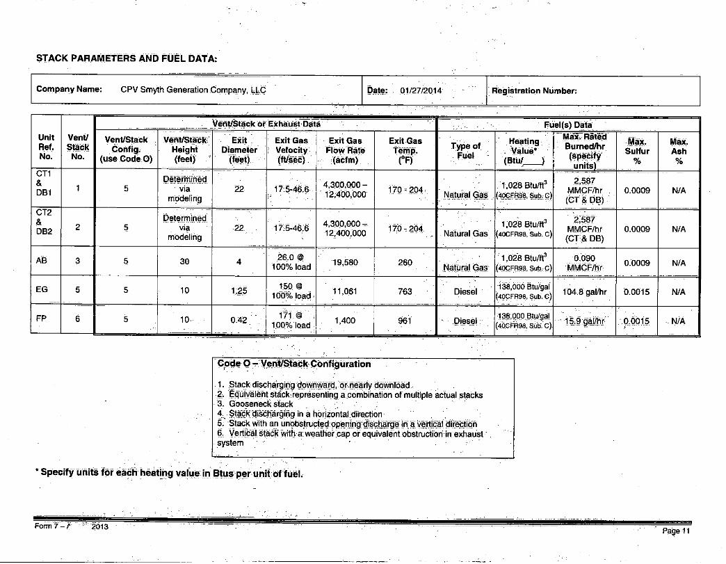
STACK PARAMETERS AND FUEL DATA:
Company Name: CPV Smyth Generation Company, LLC Date: 01/27/2014 Registration Number:
Unit Ref. No.
Vent/ Stack
No.
Vent/Stack or Exhaust Data .. Fuel(s) Data
Unit Ref. No.
Vent/ Stack
No.
Vent/Stack Config.
(use Code 0)
Vent/Stack Height (feet) '
Exit Diameter
(feet)
Exit Gas i Velocity
(ft/sec)
Exit Gas Flow Rate
(acfrn)
Exit Gas Temp. (°F)
Type of Fuel
Heating , Value* (Btu/ J
Max. Rated Burned/hr (specify units)
Max. Sulfur
%
Max. Ash %
CT1 & DB1
1 5 Determined
via modeling
22 17.5-46.6 4,300,000-' 12,400,000 170-204
Natural Gas 1,028 Btu/ft3
(40CFR98, Sub. C)
2,587 MMCF/hr (CT & DB)
0.0009 N/A
CT2 & DB2
2 5 Determined
via modeling
22 17.5-46.6 4,300,000 -12,400,000 170-204
Natural Gas 1,028 Btu/ft3
(40CFR98, Sub. C)
2,587 MMCF/hr (CT & DB)
0.0009 N/A
AB 3 5 30 4 26.0 @ 100% load 19,580 260
Natural Gas 1,028 Btu/ft3
(40CFR98, Sub. C) 0.090
MMCF/hr 0.0009 N/A
EG 5 5 10 1.25 150 @ 100% load 11,061 763 Diesel
138,000 Btu/gal
(40CFR98, Sub. C) 104.8 gal/hr 0.0015 N/A
FP 6 5 10 0.42 171 @ 100% load 1,400 961 • Diesel
138,000 Btu/gal
(40CFR98, Sub. C) • 15,9 gal/hr 0.0015 N/A
Code O - Vent/Stack Conf igurat ion
1. Stack discharging downward, or nearly download 2. Equiyaie^ of multiple actual stacks 3. Gooseneck stack 4 V Stack'd^^^ 5 - Stack with an unobstructed opening discharge in a vertical direction 6, Vertical stack with a weather cap or equivalent obstruction in exhaust system
* Specify units for each heating value in Btus per unit of fuel.
Form 7 - / 2013 Page 11

;PRQp:QiS£D-1>ERMfr'-tTMWF0R CRITERIA POLLUTANTS:
Company Name: CPV Smyth Generation Company, LLC - r Date: 01/27/2014 Registration; Number: I
Unit Ref. No.
Proposed Permit Limits for Criteria Pollutants
Unit Ref. No.
P W T
(Particulate Matter)
Pm\o?fi
, (10 pM or . smaller particulate
. . m a t t e r )
PM 2.5 = " (2.5 uM or
smaller particulate
matter)
so2
(Sulfur Dioxide)
NOx
(Nitrogen Oxides)
CO
(Carbon Monoxide)
VOC 8
(Volatile Organic
Compounds) •
Pb
(Lead) Unit Ref. No.
lbs/hr tons/yr lbs/hr tons/yr lbs/hr tons/yr lbs/hr tons/yr lbs/hr tons/yr lbs/hr tons/yr lbs/hr tons/yr lbs/hr tons/yr CTi & DB1 12.9 39.5 12.9 39.5 12.9 39.5 3.8 13.2 19.6 74.7 11.9 47.7 6.8 22.1 N/A N/A
CT2& DB2 12.9 39.5 12.9 39.5 12.9 39.5 . 3.8 13.2 19.6 74.7 11.9 47.7 6.8
i 22.1 N/A N/A
AB 0.46 0.92 0.46 0.92 0.46 0.92 0.13 0.26 1.01 2.02 3.42 6.83 0.47 . 1
j _ ..
0.94 N/A N/A
EG 0.66 '' • 0.17 0.66 0.17 0.66 0.17 0.022 0.01 21.2 5.29 11.6 2.89 4.30 1.07 • N/A , N/A
FP - 0.10 0.03 0.10 0.03 0.10 0.03 0.003 0.001 2.07 0.52 1.81 0.45 0.26 . i
0.06 N/A N/A
. AJ: hy'.r ''• TOTAL: 27.0 V 80.1 27.0 80.1 27.0 80.1 7.76 26.6 63.5 157.2 40.6 105.6 18.6 • -46.3 \
Yv •:• :>Y:. :
on per Unit Ref. No.)
' PM, PM-tOVPMiiJS, land VOC should also be split up by component and reported under the Proposed Permit Limits for Toxic Pollutants/HAPs
'PM-10 and PM 2.5 includes filterable and condensable. I - ,
Form 7 - April 8, 2013 Page:12':

PROPOSED PERMIT LIMITS FOR TOXIC POLLUTANTS/HAPS:
Company Name: CPV Smyth Generation Company, LLC Date: 01/27/2014 Registration Number:
Unit Ref. No.
Proposed Permit Limits for Toxic/HAP Pollutants*
Unit Ref. No.
HAP Name: Acrolein
CAS#: 107028
HAP Name: Forma|dehyde
CAS#: 50000
HAP Name: Cadmium
CAS #: 7440439
HAR.Name:
CAS#:
HAP Name:
CAS#:
HAP Name:
CAS #:
HAP Name:
CAS#:
HAP Name:
CAS#: Unit Ref. No.
lbs/hr tons/yr lbs/hr tons/yr lbs/hr tons/yr lbs/hr tons/yr lbs/hr tons/yr lbs/hr tons/yr lbs/hr tons/yr lbs/hr tons/yr
CT1 0.0145 0.064 0.250 1.09 0.0025 0.0109
CT2 0.0145 0.064 0.250 1.09 0.0025 0.0109
• ' • -
,
TOTAL: 0.029 0.127 0-499 2.19 :, 0.0050 0.0219 • '. .'• m s and per Unit Ref. No.)
* Specify the name of the toxic pollutant/HAPforeach Unit Ref. No. along with the respective CAS Nurnber. Toxic Pollutant means a pollutant on the designated list in the Form 7 Instructions document. Particulate matter and volatile organic compounds are not toxic pollutants as generic classes of substances, but individual substances within these classes may be toxic pollutants because their toxic properties or because a TLV (tm) has been established.
Form 7 - f " 2013 Page 13

PROPOSED PERMIT LIMITS FOP. OTHER REGULATED POLLUTANTS:
Company Name: CPV Smyth Generation Company, LLC Date: 01/27/2014 Registration Number:
Unit Ref. No.
Proposed Permit Limits for Other Regulated Pollutants*
Unit Ref. No.
Pollutant Name:
Ammonia
Pollutant Name:
Sulfuric Acid
Pollutant Name:
C0 2e
Pollutant Name: Pollutant Name: Pollutant Name: Pollutant Name: Pollutant Name:
Unit Ref. No.
lbs/hr tons/yr lbs/hr tons/yr lbs/hr tons/yr lbs/hr tons/yr lbs/hr tons/yr lbs/hr tons/yr lbs/hr tons/yr lbs/hr tons/yr GT1 & DB1 18.1 65,2 2.5 8.6 321,399 1,156,440
CT2 & DB2 18.1 65.2 2.5 8.6 321,399 1,156,440
t
AB N/A N/A 0.01 0.02 10,813 21,627
EG N/A N/A Q0017 0.0004 2,366 592 i
FP N/A N/A . 0.0003. 0.0001 360 90
! . ••. : . : ;Vi''
<•:.. L;. '.- :
TOTAL: 36:2 130:4 5.0 17.2 656,337 2,335,189 . - !" . . v
r:'^ m and per Unit Ref. No.)
* ) O ^ F # M " l a ^ r P ^ i l u W include Fluorides, Sulfuric Acid Mist, Hydrogen Sulfide (H2S), Total Reduced Sulfur (including.HjS), Reduced Suifur Compounds (including H2S), Municipal Waste Combustor Organics (measured as total tetra-through octa-chlorinated dibenzo-p-djoxiris |md d
Form 7 - April 8, 2013 Page 14

Waste Combustor Metals (measured as particulate matter), Municipal Waste Combustor Acid Gases (measured as the sum of S 0 2 and HCI), and Municipal Solid Waste Landfill Emissions (measured nonrnethane organic compounds).) PROPOSED PERMIT LIMITS FOR GREENHOUSE GASES (GHGs) ON MASS BASIS: FOR PSD MAJOR SOURCES ONLY
Company Name: CPV Smyth Generation Company, LLC Date: 01/27/2014 Registration Number:
Proposed Permit Limits for. GHG Pollutants on Mass Basis
co2 NzO CH 4
MFCs PFCs SF 6 Total GHGs Unit
Ref. No. (Carbon Dioxide) (Nitrous Oxide) (Methane) : (Hydrofluoro-
carbons) (Perfluoro-carbons)
(Sulfur Hexafluoride)
lbs/hr tons/yr lbs/hr tons/yr lbs/hr : tons/yr lbs/hr tons/yr lbs/hr tons/yr ; lbs/hr tons/yr lbs/hr tons/yr CT1 & DB1 321,071 1,155,266 0.60 2.14 : 5.96 21.4 N/A N/A N/A N/A N/A N/A 321,078 1,155,290
CT2& DB2 321,071 1,155,266 0.60 2.14 5.96 21.4 N/A N/A N/A N/A N/A N/A 321,078 1,155,290
AB 10,802 21,605 0.020 0.041 0.204 0.41 N/A N/A N/A N/A N/A N/A 10,802 21,606
EG 2,359 590 0.019 0.0048 0.096 0.024 N/A N/A N/A N/A , N/A N/A 2,359 590
FP 359 90 0.0029 0.0007 0.015 0.0036 N/A N/A N/A N/A N/A N/A 359 90
TOTAL: 655,662 2,332,816 1 24 4.33 12.2 . 43.3 655,676 2,335,189
I X I Estimated Emission Calculations Attached (totals and per Unit Ref. No.)
Form 7 - A ' ' " 2013 Page 15

ONLY 2 EQUIVALENT EMISSIONS (C02e) BASIS: FOR PSD MAJOR SOURCES
C , ,
Company Name: CPV Smyth Generation Company, LLC Date: 01/27/2014 Registration Number:
Unit Ref. No.
Proposed Permit Limits for GHG Pollutants on C 0 2 Equivalent Basis
Unit Ref. No.
COz
(Carbon Dioxide)
N20
(Nitrous Oxide)
GH4
(Methane)
MFCs
(Hydrofluoro-carbons)
PFCs
(Perfluoro-carbons)
SF6
(Sulfur Hexafluoride)
v:/'T^'rGiHGs
Unit Ref. No.
lbs/hr tons/yr lbs/hr tons/yr lbs/hr tons/yr lbs/hr tOns/yr lbs/hr tons/yr lbs/hr tons/yr lbs/hr tons/yr CT1 & DB1 321,071 1,155,266 , 179 638 149 535 N/A N/A N/A N/A N/A ! N/A
_ l L \ L : ' j 321,399 1,156,440
CT2& DB2 321,071 1,155,266 179 638 149 535 N/A N/A N/A N/A N/A
j • ; • N/A ' 321,399 1,156,440
AB 10,802 21,605 • 6 13 .4 9 N/A N/A N/A N/A N/A N/A. 10,813 21,627
EG 2,359 .590 6 1 2 0,5 N/A N/A N/A N/A N/A N/A . 2,366 592
FP 359 90 : 1 0.2 0.03 0.08 N/A N/A N/A N/A N/A N/A !. 360. . 90
. '.' V
j . -' i • • '•.. r
j
: ;:.;.\
;' 'i['-.:. '.
TOTAL: . 655,662 2,332,816 371 1,290 280 1,080 N/A N/A N/A N/A N/A N/A 656,337 ; 2,355,189
per Unit Ref. No.)
Form 7 — April 8,t2013T Page 16

OPERATING PERIODS:
Company Name: CPV Smyth Generation Company, LLC Date: 01/27/2014 Registration Number:
Unit Ref. No.
Percent Annual Use/Throughput by Season Normal Proces^Equipm^tOpera i Schedule
Maximum Prpcess/Equipment Operating Schedule Unit
Ref. No.
December- March June September Hours per Day
Days per Week
Weeks per • Year
• Hours per Day
Days per Week
Weeks per Year
Unit Ref. No. February May August November
Hours per Day
Days per Week
Weeks per • Year
• Hours per Day
Days per Week
Weeks per Year
CT1 25 25 ' 25 25 24 7 52 24 7 52
CT2 25 25 25 25 24 7 52 24 7 52
DB1 25 25 25
• 25 -24 • 5 25 • < 3,000 hours per year dependent upon demand
DB2 25 25 25 25 24 5 ' 25 , < 3,000 hours per year dependent upon demand
AB 25 25 25 ; 25 - • •• 12 ' 2 • • 52 < 4,000 hours per year dependent upon demand
EG 25 25 25 25 1 1 52 ; < 500 hours per year dependent upon duration of emergency situations
FP 25 25 25 25 . 1 : 1 52 < 500 hours per year dependent upon duration
of emergency situations
Maximum Facility Operating Schedule
Hours per Day
24
Days per Week
7
Weeks per Year
52 .
Form 7 - A 2013

CPV Smyth Generation Project PSD Air Permit Application
APPENDIX B
Emission CalcuEations
<••
I t

Summary of ^ Annual Emissions GPVSm
Facility-Wide Potential An
Pollutant U n i t l
(CT&HRSG)
(tpy)
Unit 2 , v (CT&HRSG)
(tPV)
Auxiliary Boiler (tPV)
Emergency Generator ;
' (tpy)
Fire Pump
(tpy)
Facility Total
(tpy)
No, ; u ^ . . 74.7 . ;.' ^ 74.7 2.02 "". 5.29 0.52 157.2
CO 47.7 47.7 6.83 2.89 0.45 105.6
VOC 22.1 22.1 0.94 • / ( 1.07 0.06 46.3
so2 13.2 1 13.2 0.26 ' 0.005 0.001 26.6
PM/PM 1 0/PM 2 5 • 39:5 , 39.5 0.92 . 0.17 0.03 80.1
C02 1,155:266' ; , 1.155.266 21,605 590 89.69 2,332,816
CH4 - 21.4. : • 21.4 0.407 0.024 0.0036 43.3
N20 214 . . .2,14 • 0.041 0.005 0.0007 ] 4.33
C0 2 e 1,156,440 •': 1,156,440 21,627 ' 592 90 2,335,189
H 2 S0 4 :;s:v^58:P' ':'"X"-:; - 8 6 . 0.02 ; 0.0004 0.0001 17.3
Lead (Pb) j l w ' 4.5E-03 ' ; 4.5E-03 9.1E-05 ' 2.8E-06 4.2E-07 0.009
NH| - j ; i >0 ; r> 65r2 65.2 N/A N/A N/A 130.3
Total HAPS . ' K'^^feif •'•"•v 4.17 0.35 . 0.02. 0,004 8.7
Summary of Annual Emissions CPV Smyth Emission Gales Draft 01-24-2014

Vendor Emissions from Combustion Turbines & Duct Burner CPV Smyth Generation Company, LLC
AMBIENT CONDITIONS: ALSTOM CASE #: #22 #21
100*F #8 #9 #10 #20 #19
90"F #3 #4 #5
Number of GTs Operating 2 2 2 2 2 2 2 2 2 2 Operating Load. 100% 100% 75% 50% 4% 100% 100% 75% 50% 4% Fuel Heating Value, Btu/lb (LHV) 20,885 20,885 20,885 20,885 20885.00 20,885 20885.00 20,885 20,885 20,885 Fuel Heating Value, Btu/lb (HHV) 23,156 23,156 23,156 23,156 23156.00 23,156 23156.00 23,156 23,156 23,156 Eavporative Cooler Status ON ON OFF OFF OFF ON ON OFF OFF OFF Duct Burner Status ON OFF OFF OFF OFF ON OFF OFF OFF OFF Chiller Status ON ON OFF OFF OFF ON ON OFF OFF OFF Ambient Relative Humidity, % 100 100 30 30 30.00 100 100.00 50 50 50 BAROMETRIC PRESSURE, psia 14.38 14.38 14.38 14.38 15.38 16.38 17.38 18.38 19.38 20.38 GT Heat Input (MMBtu/hr/unit, LHV) 1,827 1,827 1,200 914 355 1,827 1,827 1,245 944 363 GT Heat Input (MMBtu/hr/unit, HHV) 2,026 2,026 1,331 1,013 394.08 2,026 2025.88 1,381 1,047 402 DB Heat Input (MMBtu/hr/unit, LHV) 389 0 0 0 0.00 389 0.00 0 0 0 DB Heat Input (MMBtu/hr/unit, HHV) 431 0 0 0 0 431 0 0 0 0 Net Power (kW) 703,900 604,600 385,000 274,900 55,300 711,800 611,400 406,900 290,100 58,600 Gross Power (kW) 705,400 606,100 386,500 276,400 56800.00 713,300 612900.00 408,400 291,600 60,100 Heat Rate (Btu/kW-hr, gross) 6,967 6,685 6,887 7,333 13876.02 6,890 6610.79 6,762 7,181 13,380
HRSG STACK EXHAUST GAS Exhaust Flow, Ib/hr 3,745.747 3,727,139 2,511,261 2,063,268 1428654.10 3,745,747 3727138.90 2,562,907 2,096,519 1,443,985 Stack Temprature, °F 182.7 204.1 178.7 174.2 195.6 178.5 195.5 175.1 170.4 193.8 0 2 , Vol. % 10.00% 11.79% 11.87% 12.49% 15.97% 10.00% 11.79% 11.65% 12.28% 15.84%
CO;, Vol. % 4.93% 4.11% 3.99% 3.71% 2.11% 4.93% 4.11% 4.05% 3.76% 2.13% H 20, Vol. % 10.87% 9.26% 9.80% 9.25% 6.17% 10.87% 9.26% 10.38% 9.83% 6.68% N 2, Vol. % 73.33% 73.96% 73.45% 73.66% 74.85% 73.33% 73.96% 73.04% 73.26% 74.47% Ar, Vol. % 0.88% 0.88% 0.88% 0.88% 0.90% 0.88% 0.88% 0.87% 0.88% 0.89% MW, ib/lb-mole 28.22 28.32 28.25 28,28 28.48 28.22 28.32 28.19 28.23 28.43
HRSG EXHAUST STACK EMISSIONS (PER STACK): NOX, ppmvd® 15% 0 2 2.0 2.0 2.0 2.0 2.0 2.0 2.0 2.0 2.0 2.0 NOX, Ib/hr as N02 17.8 14.7 9.7 7.4 2.9 17.8 14.7 10.0 7.6 2.9 VOC, ppmvd @ 15% O 2 as CH4 2.0 1.0 1.0 1.0 2.0 2.0 1.0 1.0 1.0 2.0 VOC, Ib/hr as CH4 6.2 2.6 1.7 1.3 1.0 6.2 2.6 1.7 1.3 1.0 CO, ppmvd @ 15% O 2 2.0 2.0 2.0 2.0 2.0 2.0 2.0 2.0 2.0 2.0 CO, Ib/hr 10.8 8.9 5.9 4.5 1.7 10.8 8.9 6.1 4.6 1.8 S02, Ib/hr 3.2 2.7 1.8 1.3 0.5 3.2 2.7 1.8 1.4 0.5 H2S04, Ib/hr 2.0 1.7 1.1 0.9 0.3 2.0 1.7 1.2 0.9 0.3 H2S04, lb/MMBtu 0.00081 0.00084 0.00083 0.00089 0.00076 0.00081 0.00084 0.00087 0.00086 0.00075 PM/PM10/PM2 5 , Ib/hr 12.0 7.2 8.7 8.0 2.1 12.0 7.2 9.0 8.2 2.1 PM/PM10/PM2 5 , lb/MMBtu 0,0049 0.0036 0.0065 0.0079 0.0053 0.0049 0.0036 0.0065 0.0078 0.0052 NH3, ppmvd @ 15% O 2 5.0 5.0 5.0 5.0 5.0 5.0 5.0 5.0 5.0 5.0 NH3, Ib/hr 16.5 13.6 8.9 6.8 2.6 16.5 13.6 9.3 7.0 2.7 C0 2 , Ib/hr 292,053 240.790 158,189 120,456 46,839 292,053 240,790 164,123 124,443 47,791 CH„ Ib/hr 5.42 4.47 2.93 2.23 0.87 5.42 4.47 3.04 2.31 0.89 N 20, Ib/hr 0.54 0.45 0.29 0.22 0.09 0.54 0.45 0.30 0.23 0.09 C0 2e, Ib/hr 292,350 241,035 158,350 120,579 46,887 292,350 241,035 164,290 124,569 47,839 C0 2e, lb/MW-hr (gross) 828.9 795.4 819.4 872.5 1650.9 819.7 786.5 804.6 854.4 1592.0
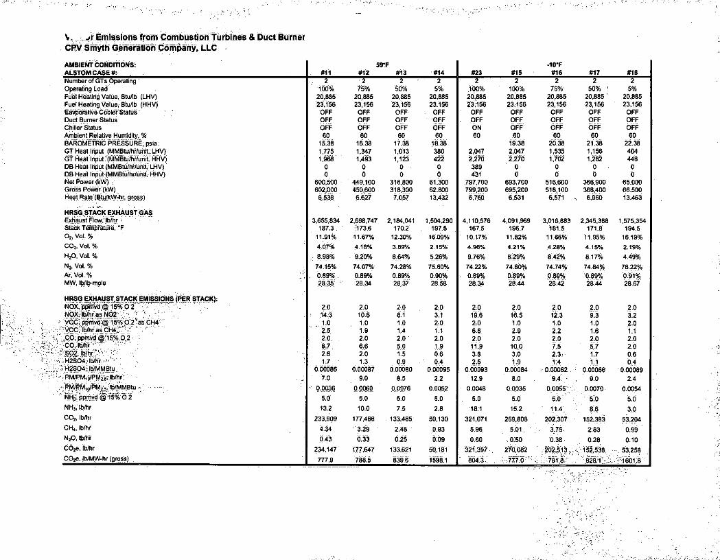
V .»r Emissions from Combustion Turbines & Duct Burner CPV Smyth Generation Company, LLC
AMBIENT CONDITIONS: ALSTOM CASE #: #11
59-F #12 #13 #14 #23 #15
-10*F #16 #17 #18
Number of GTs Operating 2 2 2 2 2 2 2 • 2 i 2 Operating Load 100% 75% 50% 5% 100% 100% 75% 50% | 5% Fuel Heating Value, Btu/lb (LHV) 20,885 20,885 20,885 20,885 20.885 20,885 20,885 20,885 20,885 Fuel Heating Value, Btu/lb (HHV) 23.156 23,156 23,156 23,156 23.156 23,156 23,156 23,156 23,156 Eavporative Cooler Status OFF OFF OFF OFF OFF OFF OFF OFF OFF Duct Burner Status OFF OFF OFF OFF . OFF OFF OFF OFF OFF Chiller Status OFF OFF OFF OFF ON OFF OFF OFF OFF Ambient Relative Humidity, % 60 60 60 60 60 60 60 60 60 BAROMETRIC PRESSURE; psia 15.38 16.38 17.38 18.38 19.38 20.38 21.38 22.38 GT Heat Input (MMBtu/hr/unit, LHV) 1,775 1,347 1,013 380 2,047 2,047 1,535 1,156 404 GT Heat Input! (MMBtu/hf/unit, HHV) 1.968 1,493 1,123 422 2.270 2.270 1,702 1,282 448 DB Heat Input (MMBtu/hr/uhit,- LHV) 0 0 0 . 0 389 0 0 0 0 DB Heat Input (MMBtu/hr/unit, HHV) 0 0 0 0 431 0 0 6 0 Net Power (kW) • 600,500 449,100 316,800 61,300 797,700 693,700 516,600 366,900 65,000 Gross Power (kW) . 602,000 450,600 318,300 62,800 799,200 695,200 518,100 368,400 66,500 Heat Rate (Btu/kW-hr, gross) 6.538 6.627 7,057 13.432 6.760 6.531 6,571 ^ 6.960 13,463
HRSG.STACK EXHAUST GAS Exhaust Flow, Ib/hr 3,655,834 2,698,747 2,184,041 1,504,290 4,110,576 4,091,969 3,016,883 2,345,388 1,575,354 Stack Temprature, °F 187.3 173 6 170.2 197.5 1675 196.7 181.5 171.8 194.5 O;, Voi:% 11.91% 11.67% 12.30% 16.09% 10.17% 11.82% 11.66% 11.95% 16.19% CO;, Vol % 4,07% 4.18% 3.89% 2.15% 4.96% 4.21% 4.28% 4.15% 2.19% H 20, Vol. % : 8 98% 9.20% 6.64% 5.26% 9.76% 8.29% 8.42% 817% 4.49% N 2, Vol. % 74 15% 74.07% 74.28% 75.60% 74.22% 7480% 74.74% 74.84% 76.22% Ar, vol. % ; ; ; , 0.89% 0.89% 0.89% 0.90% 0.89% 0.89% 0.89% 0.89% 0.91% MW, Ib/lb-mole 28.35 28.34 28.37 28.58 28.34 28.44 28:42 28.44 28.67
HRSG EXHAUST,STACK EMISSIONS (PER STACK): NOX, ppmvd © 15% 6 2 • ; / • ' 2.0 2.0 2.0 2.0 2.0 2.0 2.0 2.0 2.0 NOXv Ib/hr as N02 - ' :- • 14.3 10.8 8.1 3.1 19.6 16.5 12.3 9.3 3.2 VOC; ppmvd @ 15% 0 2 as CH4 1.0 1.0 1.0 2.0 2.0 1,0 1.0 1.0 2.0 VOC, Ib/hr as CH4."" ' V" " 2.5 1.9 1.4 1.1 68 2.9 2.2 1.6 1.1 fib; ppmvd @ri5%,0 2 . 20 2.0 2.0 2.0 2.0 2.0 2.0 2.0 2.0 c o . ib/hf ' 8.7 6.6 5.0 1.9 11.9 10.6 7.5 57 2.0 S02. Ib/hr' 2.6 2.0 1.5 0.6 3.8 3.0 2.3 1.7 0.6 H2S04, lb/hr " 1.7 1.3 0.9 0.4 2.5 1.9 1.4 1.1 6.4
, H2S04; lb/MMBtu 0,00086 0.00087 0.00080 0.00095 0.00093 0.00084 0.00082 0.00086 0.00089 PM/PM,o/PM2„: Ib/hr 7.0 9.0 8.5 2.2 12.9 8.0 9.4 9.0 2^4 RM/PM10/PMi'5, lb/MMBtu- 0.0036 0.0060 0.0076 0.0052 0.0048 0.0035 0.0055 0.0070 0.0054 NH,', ppmvd @ 15% 0 2 5.0 5.0 5.0 50 5.0 5,0 5.0 5.0 5.0 NH3, Ib/hr 13.2 10.0 7.5 2.8 18.1 15.2 11.4 . 8.6 3,0 COj, lb/hr 233,909 177,466 133,485 50,130 321,071 269,808 202,307 152.383 53,204 CH 4, Ib/hr 4:34 3.29 2:48 0.93 5.96 . 501 ' 3.75 2:83 0.99 N 20, Ib/hr 0.43 0.33 0.25 0.09 0.60 o:so 0.38 0.28 0.10 6626, Ib/hr 234,147 177.647 133,621 50.181 321.397 270,082 202,513 • 152,538 53.258 COje. lb/MW-hr (gross) 777.9 788.5 839.6 1598.1 " 804.3 777.6 781.8 . ": 828.1 1601.8

Summary of Annual Emissions CPV Smyth Generation Company, LLC
1/27/2014
Startup/Shutdown Operating Data hot starts/unit 250 number/yr 0.93 hours/event 0 Min hours downtime with event 55.8 minutes per event warm starts/unit 0 number/yr 2.10 hours/event 8 Min hours downtime with event 125.8 minutes per event cold starts/unit 50 number/yr 2.99 hours/event 60 Min hours downtime with event 179.5 minutes per event
[Transition To/From Low Loac 250 number/yr 0.40 hours/event 0 Min hours downtime with event 24.0 minutes per event [shutdowns/unit 300 number/yr 0.18 hours/event 0 Min hours downtime with event 10.7 minutes per event
Startup/Shutdown Emissions Self-Correcting Analysis
NOx CO VOC Emissions per hot start lbs 50.0 47.0 38.8 Emissions per warm start lbs 56.0 71.0 69.0 Emissions per cold start lbs 61.0 77.0 73.0 Emissions per transition lbs 2.9 32.0 48.0 Emissions per shutdown lbs 4.6 17.0 25.0 Hot start - duration (including downtime) hrs 0.9 0.9 0.9 Warm start - duration (including downtime) hrs 10.1 10.1 10.1 Cold start - duration (including downtime) hrs 63.0 63.0 63.0 Transition - duration (including downtime) hrs 0.4 0.4 0.4 Shutdown - duration of event (include downtime hrs 0.2 0.2 0.2
Hot start - avg hourly emissions Ib/hr 51.14 47.69 39.08 Warm start - avg hourly emissions Ib/hr 5.55 7.03 6.83 Cold start - avg hourly emissions Ib/hr 0.97 1.22 1.16 Transition - avg hourly emissions Ib/hr 4.82 33.20 48.66 Shutdown - avg hourly emissions Ib/hr 17.83 25.04 28.26 Steady state average hourly (annual) lb/hr 16.12 9.80 3.97 Transition hourly emissions (-10°F) Ib/hr 3.20 2.00 1.10 Hot start - self correcting? Ib/hr no no no Warm start - serf correcting? lb/hr yes yes no Cold start - self correcting? Ib/hr yes yes yes Transition - self correcting? Ib/hr yes no no shutdown - serf correcting? Ib/hr no no no
Startup/Shutdown Potential Emissions Increase (tpy/unit) SUSDType NOx CO VOC Hot Start 4.07 4.40 4,08 Warm Start - . 0.00 Cold Start - - -Transition - 1.17 2.23 Shutdown 0.05 0.41 0.65 TOTAL 4.11 4.81 4.73
SU-SD CPV Smyth Emission Calcs D .4-2014

Emissions From Ancillary Equipment CPV Smyth Generation Company, LLC
Emissions f rom Ancil lary Equipment (tpy)
Pollutant Auxiliary Boiler Emergency Generator Fire Pump
Pollutant 92.4 MMBtu/hr 1500 kW 235 kW
NOx 9 ppmvd @ 3% 0 2 6.4 g/BHP 4.0 g/kW NOx 0.011 lb/MMBtu 1.46 lb/MMBtu 0.94 lb/MMBtu
NOx
1.010 lb/hr 21,16 Ib/hr 2.07 Ib/hr
NOx
2.02 TPY 5.29 TPY 0.52 TPY CO 50 ppmvd @ 3% 0 2 3.5 g/kW 3.5 g/kW CO
0.0370 lb/MMBtu 0.80 lb/MMBtu 0.82 lb/MMBtu
CO
3.4158 Ib/hr 11.57 Ib/hr 1.81 Ib/hr
CO
6.83 TPY 2.89 TPY 0.45 TPY VOC 12 ppmvd @ 3% 0 2 1.3 g/kW 0.5 g/kW VOC
0.0051 lb/MMBtu 0.16 lb/MMBtu 0.10 lb/MMBtu VOC
0.4691 Ib/hr 4.30 Ib/hr 0.26 Ib/hr
VOC
0.94 TPY 1.07 TPY 0.06 TPY
PM 1 0/PM 2. 5 N/A ppmvd @ 3% 0 2 0.2 g/kW 0.2 g/kW PM 1 0/PM 2. 5
0.005 lb/MMBtu 0.01 lb/MMBtu 0.01 lb/MMBtu PM 1 0/PM 2. 5
0.4620 Ib/hr 0.66 Ib/hr 0.10 Ib/hr
PM 1 0/PM 2. 5
0.92 TPY 0.17 TPY 0.03 TPY
S0 2 0.0014 lb/MMBtu 0.00 lb/MMBtu 0.00 lb/MMBtu S0 2
0.1294 lb/hr 0.02 Ib/hr 0.00 Ib/hr S0 2
0.26 TPY 0.01 TPY 0.001 TPY H 2 S0 4 0.00011 lb/MMBtu 0.00011 lb/MMBtu 0.00011 lb/MMBtu H 2 S0 4
0.0099 Ib/hr 0.00166092 Ib/hr 0.00025266 Ib/hr H 2 S0 4
0.02 TPY 0.0004 TPY 0.0001 TPY
Pb 4.82-07 lb/MMBtu 1.42-05 lb/MMBtu 1.42-05 lb/MMBtu Pb 4.5E-05 Ib/hr 2.02-04 Ib/hr 0.0000308 Ib/hr
Pb
8.9E-05 TPY 5.12-05 TPY 7.72-06 TPY C0 2 116.9 lb/MMBtu 163.1 lb/MMBtu 163.1 lb/MMBtu C0 2
10,802 Ib/hr 2,359 Ib/hr 359 Ib/hr C0 2
21,605 TPY 590 TPY 90 TPY
CH4 0.0022 lb/MMBtu 0.0066 lb/MMBtu 0.0066 lb/MMBtu CH4 0.2037 Ib/hr 0.096 Ib/hr 0.015 Ib/hr
CH4
0.41 TPY 0.0239 TPY 0.0036 TPY
N 20 0.00022 lb/MMBtu 0.0013 lb/MMBtu 0.0013 lb/MMBtu N 20 0.0204 Ib/hr 1.92-02 Ib/hr 0.0029106 Ib/hr
N 20
0.041 TPY 4.82-03 TPY 7.32-04 TPY
C0 2e 10,814 Ib/hr 2,367 Ib/hr 360 lb/hr C0 2e 21,627 TPY 592 TPY 90 TPY
NOT2S: Natural Gas S02 emissions based upon a sulfur content of 0.5 gr/100 dscf ULSD S02 emissions based upon a sulfur content of 15 ppmw Aux Boiler and Gas Heater criteria pollutant emission factors from BACT analysis Emergency Generator criteria polluant emission factors based on Tier 2 emission standards in 40 CFR 89. Fire Pump criteria pollutant emission factors based on post -2009 emission standards in 40 CFR 60 Subpart llll. H2S04 emissions assume a 5% conversion of S02 -> S03 (on a molar basis) Fuel specific C02, CH4 and N20 emission factors from 40 CFR 98, Subpart C Pb emission factor for ULSD from AP-42 Section 3.1
ancillary equipment CPV Smyth Emission Calcs Draft 01-24-2014
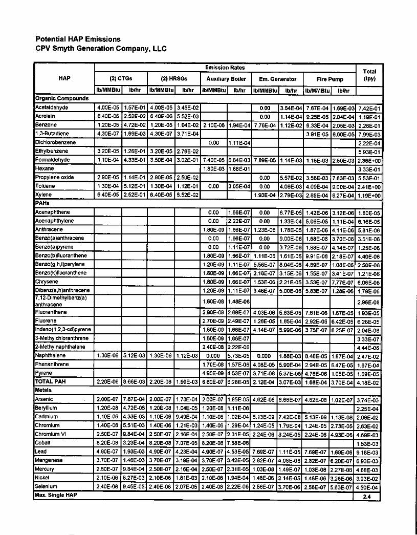
Potential HAP Emissions CPV Smyth Generation Company, LLC
HAP
Emission Rates Total
HAP (2) CTGs (2) HRSGs Auxiliary Boiler Em. Generator Fire Pump (tpy) HAP
lb/MMBtu Ib/hr lb/MMBtu Ib/hr lb/MMBtu Ib/hr lb/MMBtu | Ib/hr lb/MMBtu lb/hr Organic Compounds
Acetaldehyde 4.00E-05 1.57E-01 4.00E-05 3.45E-02 0.00 3.642-04 7.67E-04 1.69E-03 7.422-01 Acrolein 6.40E-06 2.52E-02 6.40E-06 5.522-03 0.00 1.142-04 9.25E-05 2.04E-04 1.19E-01 Benzene 1.20E-05 4.72E-02 1.202-05 1.04E-02 2.10E-06 1.94E-04 7.76E-04 1.12E-02 9.33E-04 2.05E-03 2.262-01 1,3-Butadiene 4.30E-07 1.69E-03 4.302-07 3.712-04 3.91 E-05 8.60E-05 7.992-03 Dichlorobenzene 0.00 1.11E-04 2.222-04 Ethylbenzene 3.20E-05 1.26E-01 3.20E-05 2.782-02 5.932-01 Formaldehyde 1.10E-04 4.33E-01 3.50E-04 3.022-01 7.40E-05 6.84E-03 7.89E-05 1.142-03 1.18E-03 2.60E-03 2.362+00 Hexane 1.80E-03 1.66E-01 3:332-01 Propylene oxide 2.90E-05 1.14E-01 2.90E-05 2.502-02 0.00 5.572-02 3.56E-03 7.83E-03 5.532-01 Toluene t.302-04 5.12E-01 1.302-04 1.122-01 0.00 3.05E-04 0.00 4.062-03 4.09E-04 9.002-04 2.41 E+O0 Xylene 6.40E-05 2.52E-01 6.402-05 5.522-02 1.93E-04 2.792-03 2.85E-04 6.272-04 1.19E+00 PAHs
Acenaphthene 0.00 1.66E-07 0.00 6.772-05 1.42E-06 3.12E-06 1.802-05 Acenaphthylene 0.00 2.22E-07 0.00 1.332-04 5.06E-05 1.11E-04 6.162-05 Anthracene 1.802-09 1.66E-07 1.23E-06 1.782-05 1.872-08 4.11 E-06 5.812-06 Benzo(a)anthracene 0.00 1.66E-07 0.00 9.002-06 1.68E-06 3.70E-06 3.512-06 Benzb(a)pyrene 0.00 1.11 E-07 0.00 3.722-06 1.88E-07 4.14E-07 1.252-06 Benzo(b)fluoranthene 1.80E-09 1.66E-07 1.11E-06 1.612-05 9.912-08 2182-07 4.402-06 Benzo(g,h,i)perylene 1.20E-09 1.11 E-07 5:56E-07 8.04E-06 4.892-07 1.082-06 2.502-06 Benzo(k)fluoranthene 1.802-09 1.66E-07 2.18E-07 3.15E-06 1.552-07 3.41 E-07 1.21 E-06 Chrysene 1.802-09 1.66E-07 1.53E-06 2.21 E-05 3.53E-07 7.77E-07 6.062-06 Dibenz(a,h)anthracene 1.202-09 1.11 E-07 3.46E-07 5.002-06 5.832-07 1.282-06 1.79E-06 7,12-Dimethylbenz(a) anthracene
1.602-08 1.48E-06 2.962-06
Fluoranthene 2.902-09 2.68E-07 4.03E-06 5.832-05 7.612-06 1.672-05 1.932-05 Fluorene 2.702-09 2.49E-07 1.28E-05 1.852-04 2.922-05 6.422-05 6.282-05 lndeno(1,2,3-cd)pyrene 1.802-09 1.66E-07 4.142-07 5.992-06 3.75E-07 8.252-07 2.042-06 3-Methylchloranthrene 1.802-09 1.66E-07 3.332-07 2-Methylnaphthalene 2.402-08 2 222-08 4.442-06 Naphthalene 1.30E-06 5.12E-03 1.30E-06 1.122-03 0.000 5.73E-05 0.000 1.88E-03 8.48E-05 1.87E-04 2.472-02 Phenanthrene 1.702-08 1.57E-06 4.08E-05 5.90E-04 2.942-05 6.47E-05 1.672-04 Pyrene 4.902-09 4:53E-07 3.71 E-06 5.37E-05 4.782-06 1.05E-05 1.692-05 TOTAL PAH 2.20E-06 8.66E-03 2.20E-06 1.902-03 6.802-07 6.28E-05 2.122-04 3.07E-03 1.68E-04 3.702-04 4.182-02 Metals
Arsenic 2.00E-07 7.87E-04 2.00E-07 1.732-04 2.002-07 1.852-05 4.62E-08 6.68E-07 4.622-08 1.022-07 3.742-03 Beryllium 1.20E-08 4.72E-05 1.20E-08 1.042-05 1.202-08 1.11 E-06 2.252-04 Cadmium 1.10E-06 4332-03 1.10E-06 9.492-04 1.102-06 1.02E-04 5.132-09 7.42E-08 5.132-09 1.132-08 2.062-02 Chromium 1.40E-06 5.512-03 1.40E-06 1.212-03 1.402-06 1.29E-04 1.24E-05 1.79E-04 1.242-05 2.732-05 2.632-02 Chromium VI 2.50E-07 9.842-04 2.50E-07 2.162-04 2.502-07 2.31 E-05 2.242-06 3.242-05 2.242-06 4.932-06 4.69E-03 Cobalt 8.20E-08 3.23E-04 8.20E-08 7.072-05 8.202-08 7.58E-06 1.532-03 Lead 4.90E-07 1.932-03 4.90E-07 4.232-04 4.90E-07 4.53E-05 7.692-07 1.11 E-05 7.692-07 1.692-06 9.182-03 Manganese 3.702-07 1.462-03 3.702-07 3.192-04 3.702-07 3.42E-05 2.822-07 4.082-06 2.822-07 6.202-07 6.932-03 Mercury 2.502-07 9.842-04 2.50E-07 2.162-04 2.502-07 2.31 E-05 1.032-08 1.492-07 1.032-08 2.272-08 4.682-03 Nickel 2.102-06 8.272-03 2.10E-06 1.812-03 2.102-06 1.94E-04 1.482-06 2.14E-05 1.482-06 3.262-06 3.932-02 Selenium 2.402-08 9.452-05 2.40E-08 2.072-05 2.402-08 2.22E-06 2.562-07 3.70E-06 2.562-07 5.632-07 4.502-04 Max. Single HAP 2.4

ppfofhti^ LLC
HAP
Emission Rates Total
(tpy) HAP (2) CTGs (2) HRSGs Auxiliary Boiler Em. Generator Fire Pump
Total
(tpy) HAP
lb/MMBtu Ib/hr lb/MMBtu: Ib/hr lb/MMBtu Ib/hr lb/MMBtu Ib/hr lb/MMBtu Ib/hr
Total All HAPs 4.34E-04 1.71E+00 674E-04 5.81E-01 1.89E-03 1.74E-01 5.65E-03 8.18E-02 7.66E-03 1.69E-02 8:7 Notes:; 11; Blank entry indicates no emission factor reported .2. OrganiciHAP emission factors forCTCs areifromT based on the GalifomiaiAir Resources Boardair toxics ;''•'.<'. emission [factor database. H2S04 is based on vendor:performance data. Metal HAP^emission-factors are, frpmfAP^2Tabie :1.4i4. • . ,'1 , r ' - v. :
3: Emissionifactorsfprt^ '. • y'.."' o>i : ; i ' ; r 1V''-'"•-r. ••/v-< ; l - ' r v C f . . 4. Emissioh!fact6rs";f6r.:organics;tneieme 5. Metal emissions for the emergency generator and fire pump are Metals in Gas Turbine Fuels'; 11th Annual International Petroleum Conference, Oct;12-15; 20 detected in any.of 13 samples, the detection limit was used. - - - ' ' . . v - I 6/Hexavalent;chrome;iS!based[6n 18% of me total chr ome emissions per EPAt453/R:98^004a. . . . 7. H2SC4 emissions for aux boiler, emergency generator andifre pump are based on 5% of S02 emissionsi(massibasis):
8 TPY based upon the following annual operating hours: CTGs - 8,760;j HRSGs - 3000; Aux Boiler - 4,000; Gas Heater -2,000; Em. Engines - 500.

Potential VA Air Toxics Emissions CPV Smyth Generation Company, LLC
HAP (2) CTG
Emission Rates TLV-TWA TLV-STEL Emissions Threshold
(Ib/hr)
Emissions Threshold
(tpy) Modeling Required?
SAAC 1-Hour SAAC Annual HAP Ib/hr TPY (mg/mJ) (mg/m*)
Emissions Threshold
(Ib/hr)
Emissions Threshold
(tpy) Modeling Required? (ug/nO (ug/m')
Acetaldehyde 1.82E-01 6.90E-01 180 270 8.912+00 2.61E+01 N N/A N/A
Acrolein 2.91 E-02 1.102-01 0.23 0.69 2.282-02 3.34E-02 Y 17.25 0.46
Benzene 5.45E-02 2.072-01 32 2,112+00 4.64 N N/A N/A
1,3-Butadiene 1.95E-03 7.412-03 22 1.45E+00 3.19 N N/A N/A
Ethylbenzene 1.452-01 5.522-01 434 543 1.792+01 6.29E+01 N N/A N/A
Formaldehyde 4.99E-01 1.90E+00 1.2 2.5 8.252-02 1.74E-01 Y 62.5 2.4
Propylene oxide 1.322-01 5.002-01 48 3.172+00 6.96 N N/A N/A
Toluene 5.902-01 2.242+00 377 565.00 1.862+01 54.67 N N/A N/A
Xylene 2.912-01 1.102+00 434 651 2.152+01 6.30E+01 N N/A N/A
Naphthalene 5.90E-03 2.24E-02 52 79 2.61 E+00 7.54E+00 N N/A N/A
Arsenic 9.082-04 3.452-03 0.2 1.32E-02 0.03 N N/A N/A
Beryllium 5.45E-05 2.072-04 0.002 1.322-04 0.00 N N/A N/A
Cadmium 4.99E-03 1.90E-02 0.05 3.30E-03 7.25E-03 Y 2.5 0.1 Chromium 6.36E-03 2.41 E-02 0.5 3.30E-02 7.25E-02 N N/A N/A
Chromium VI 1.142-03 4.31 E-03 0.05 3.302-03 0.01 N N/A N/A Cobalt 3.722-04 1.412-03 0.05 3.302-03 0.01 N N/A N/A
Lead 2.222-03 8.452-03 0.15 9.902-03 2.18E-02 N N/A N/A
Manganese 1.682-03 6.382-03 5 3.302-01 0.73 N N/A N/A
Mercury 1.142-03 4.312-03 0.05 3.302-03 0.01 N N/A N/A Nickel 9.53E-03 3.62E-02 1 6.602-02 1.452-01 N N/A N/A Selenium 1.092-04 4.142-04 0.2 1.32E-02 2,902-02 N N/A N/A
CPV Smyth-Generation Project PSD Air. Permit Application
# % N D I % #
Brmance Data Equi
I t
-rl y

ALST# Smyth County (USA): KA24-2 (2011) MS, ACC, SF Performance Summary
01/06/14
Rev E
1AHV424657
1 The corrections from 'Gross Output / Efficiency' to 'Net Output / Efficiency' reflects current aux. consumption/losses for
Alstom equipment only.
2 Values for Information only.
3 Gas turbine output does not include the OTC heat rejection energy.
4 Ambient Pressure: 13.56 psia
5 Air Cooled Condenser
6 CO & SCR Catalyst considered for HRSG pressure drop calculations and stack emissions
7 PM10/PM2.5 measurements per EPA Method 201/a + 202
8 Particulate Matter exhaust emissions are the net emission values, i.e. the emission contribution above those pre-existing
in the ambient air. Alstom therefore reserves the right to correct for the pre-existing ambient air quality if required.
9 Particulate matter emissions are often below the detection limits of most of the measuring systems. Therefore if no
particulate matter is detected within maximum 4 hours of measurement, the particulate emission is deemed to have
been fulfilled.
10 Particulate Matter emission limits are valid for steady state gas turbine operating conditions and are based on a three-
hour average. ( \ / \ .
jusv for at le 11 Prior to any Particulate Matter measurements, the gas turbine must in operation continuous]
or near base load. Gas turbine inlet and exhaust system are assc
before the measurement.
12 Particulate Matter measurements may have to be repeJ
13 All values are based on the following fuel c o m p o s i ) v ^ \ \ X
e fully commiss ione j ^nd^^n condition
^ W = ^
Constituent
Nitrogen
sulfur Content is
14 The performance summary is based onj
least 8 hours at
Carbon Dioxidj
Methane 7
E t h a n e / ^ v X
P r o p a r y V X \
CASE 1 2x100%, PO, 90^ (50% RH, FA+HF^6N, SF=ON
CASE 2 2x100%, PO, 90F\\o% RH, Ej )HHF=0N, SF=OFF
CASE 3 2x75%, PO, 90F, 5bC^W%^OFF, HF=OFF, SF=OFF
CASE 4 2x50%, PO, 90F, 50% RH, EC=OFF, HF=OFF, SF=OFF
CASE 5 2xLLOC%, 90F, 50% RH, EC=OFF, HF=OFF, SF=OFF
CASE 6 2x100%, PO, 100F, 30% RH, EC+HF=ON, SF=ON
CASE 7 2x100%, PO, 100F, 30% RH, EC+HF=ON, SF=OFF
CASE 8 2x75%, PO, 100F, 30% RH, EC=OFF, HF=OFF, SF=OFF
CASE 9 2x50%, PO, 100F, 30% RH, EC=OFF, HF=OFF, SF=OFF
CASE 10 2xLLOC%, 100F, 30%.RH, EC=OFF, HF=OFF, SF=OFF
CASE 11 2x100%, PO, 59F, 60% RH, EC=OFF, HF=OFF, SF=OFF
CASE 12 2x75%, PO, 59F, 60% RH, EC=OFF, HF=OFF, SF=OFF
CASE 13 2x50%, PO, 59F, 60% RH, EC=OFF, HF=OFF, SF=OFF
CASE 14 2xLLOC%, 59F, 60% RH, EC=OFF, HF=OFF, SF=OFF
CASE 15 2x100%, PO, -10F, 60% RH, EC=OFF, HF=OFF, APH=ON, SF=OFF
CASE 16 2x75%, PO, -10F, 60% RH, EC=OFF, HF=OFF, APH=ON, SF=OFF
l o f 4

[CASE 17 2x50%, PO, -10F, 60% RH, EC=OFF( HF=OFF, APH=ON, SF=OFF | CASE 18 2xLLOC%; -10F, 60% RH, EC=OFF, HF=OFF, APH=ON, SF=OFF | CASE 19 2x100%, PO, 90F, 50% RH, CH=ON*,SF=OFF |
CASE 20 2x100%, PO, 90F, 50% RH, CH=ON*, SF=ON |
CASE 21 2x100%, PO, 100F, 30% RH; CH=ON*,SF=0FF
CASE 22 2x100%, PO, 100F, 30% RH, CH=ON*, SF=ON CASE 23 2x100%, PO, -10F, 60% RH, EC=OFF, HF=OFF, SF=ON
LLOC Low Load Operating Concept
RH Relative Humidity
EC Evaporative Cooler
HF High Fogging
CH Chiller
APH Air Preheater
SF Supplementary Firing
* Chiller ON reduces inlet temperature to 50F
Proprietary and Confidential Information: © ALSTOM Power. All rights reserved. Informatio
this document Is indicative only. No representation or warranty is gx\en or should be relied
complete or correct or will apply to any particular project. ThGZ^L^L\)end on the technical
commercial circumstances. It Is provided without l iabl l i r /^m^su^je^oAto change witho
Reproduction, use or disclosure to third parties, w i thot^ ^xpresvyr i t tp)author i tyyis^tr i
2 of 4

A L S T O M Smyth County (USA): KA24-2 (2011) MS, ACC, SF Performance Summary R e u E
CASE 1 CASE 2 CASES CASE 4 CASES CASE 6 CASE 7 " CASE8 " ' " CASES- CASE 10 CASE 11 CASE 12 CASE 13 :
2x100%, PO, 90F, 2X100K, PO, OOP. 2«75%,PO,90F, 2x50%, PO, OOF, 2xLL0C%, 90F, 50% 2x100%, PO, 100F, 2x100%, PO, 100F, 2x75%, PO, 100F, 2x50%, PO, 100F, 2xU.OC%, 100F, 30% 2x100%, PO, 59F, 2x75%, PO, 59 F, 2x50%, PO,59F, 50% RH, EC+HF=ON, 50% RH. EC+HF=ON, 50% RH, EC=OFF, 50% RH, EC=OFF, RH, EC=0FF, 30% RH, EC+HFcON. 30%RH.EC+HF=ON, 30% RH, EC=OFF, 30% RH, EO=OFF, RH, EOsOFF, 60% RH, EC=OFF, . 60% RH, EC=OFF, 60% RH, EC=OFF,
5F-0FF HF=OFF,SF=OFF HF=0FF, SF=OFF HF=OFF, SF=0FF SF=ON SF=OFF HF=OFF; SF-0FF HFeOFF, 5F=OFF HF=OFF, 5F-0FF HF=OFF, SF=OFF HF=OFF, 5F-0FF HF=OFF, SF=OFF Ambient Temperature 90.0 90.0 90.0 100.0 100.0 100.0 59.0 59.0 59.0 Relative Humidity 50.0 50.0 50.0 30.0 30.0 30.0 Number of GTs Operating 2 2 2 2 ' 2 2 2 2 Evap Cooler Status OFF OFF OFF ON OFF OFF OFF OFF HighFoggingStatus ON ON OFF OFF OFF ON OFF OFF OFF OFF OFF OFF Supplementary Firing OFF OFF OFF OFF OFF OFF OFF OFF OFF OFF OFF Combined Cycle Performance _ Gross Output 291.6 681.0 •583.0 . 386.5 318.3 Gross Efficiency (LHV) 27.3 Gross Heat Rate (LHV) Btu/kWh 6100 6476 12061 6085 6211 6614 Net Output 589,7 385.0 55.3 600.5 316.8 Net Efficiency (LHV) 56.56 55.73 27.58 56.90 53.36 Net Heat Rate (LHV) Btu/kWh 6290 6032 6122 6509 12370 6364 6100 6235 6650 12848 5912 5997 6395
Gross Output 159.5 Condenser Pressure psia 2.259 1.679 1.412 1.08S.O Stack Composition N2 vol% 70.71% 71.35% 73.2411 ( l l \ \ 26% 74.4VV \ \ "-Ttf$4% 71.48% 73.45% 73.66% 74.85% 74.15% 74.07% 74.28% 02 10.92% / ^ v Ab* lS.aWSsX- \ \ 9.10% 10.97%' 11.87% 12.49% 15.97% 11.67% 12.30% H20 14.34% 12.69% / (10.38% ^ ' '9.83% /LX \S 9.25% 6.17% 8.98% 9.20% 8.64% C02 3.76% JtpA^T] [ 5.05%
0.85% \<«7* A 0.90% 0.89% 0.89% Emissions Per HRSG x r - y /> CO ppmvd @ 15% 0, 2.0 2.0 2.0 2.0 ( ( 2.0 2.0 2.0 2.0 2.0 2.0 2.0 2.0 CO Ib/hr 6.1 \M . JJu* 6.6 CO, vol% 5.1% 4.2% 41% I I 3.8% | ' 2.1% 5.0% 4.2% 4.0% 3.7% 2.1% 4.1% 4.2% 3.9% CO, Ib/hr 281544 231370 162064 \\122953 ) ) 47518 280876 230702 156227 119034 46580 230992 175217 131866 NO, ppmvd @ 15% 0, 2.0 2.0 2.0 \>to_%y 2.0 2.0 2.0 2.0 2.0 2.0 2.0 2.0 2.0 NO, as NO, Ib/hr 17.4 14.3 10.0 %r" 2.9 17.4 14.3 9.7 7.4 2.9 14.3 10.8 8.1 V0C[asCH4) ppmvd @> 15% 0, 2.0 1.0 1.0 1.0 2,0 2.0 1.0 1.0 1.0 2.0 1.0 1.0 1.0
6.1 2.5 2,5 SO, as SO, Ib/hr 3.2 2.6 18 1.4 0.5 3.2 2.6 1.8 1.3 0.5 2.6 2.0 1.5
H,S0, Ib/hr 2.0 1.7 1.2 0.9 0.3 2.0 1.7 1.1 0,9 0.3 1.7 1.3 0.9
PM10(front half) Expected Ib/hr 6.4 5.2 6.1 4.6 . 1.8 6.4 5.2 5.9 4.5 1.7 5.2 6.6 5.0 PM10 (back half) inc. H,so* Expected Ib/hr 5.5 1.8 2.9 3.6 0.3 5.5 . 1.7 2.9 3.5 0.3 1.7 2.4 3.5 PM 1 0/PM, S Total Ib/hr 11.9 7.0 9.0 8.2 2.1 11.9 7.0 8.7 8.0 2.1 7.0 9.0 ' 8.5 NH, ppmvd @ 15% 0, 5.0 5.0 5.0 5,0 5.0 5.0 5.0 5.0 5.0 5.0 5.0 5.0 5.0 NH, Ib/hr 16.1 13.2 9.3 7.0 2.7 16.1 13.2 8.9 6.8 2.6 13.2 10.0 7.5
FOR INFORMATION ONLY

A L S T © ' M Smyth County (USA): KA24-2 (2011) MS, ACC, SF 01/06/2014
Performance Summary 1AHV424657
FOR INFORMATION ONLY
Plant Start-Up and Shutdown Emiss KA24-2 Smyth County
Projects and Customer's Information:
KA24-2 (2011)
<\ Space for Stamping (Review and Validation status)
< #
^c^x
Date Cross checked Department Name Signature
Revision History rf~>V*>
Rev. Revision Date Created by Checked by/f^"*" Approved by Brief Description
L j) A ^
^ c T ^ ^
i
Description current Revision ^ \ ^ J ^
<Ti
Main Contractor
ALSTOM | A l s t o m ( S w i t z e r l a n d ) L t d . , Brown Boveri Strasse 7, CH 5401-Baden
Replaces Customer Code ALSTOM Document Code
Responsible dept. Created by Checked by GAS NAM-US : E. Brown M. Feeney
Approved by Format C. Dougherty A4
Originator
ALSTON 1 POWER | GAS BUSINESS
Document Type Design Concept
Document Status Electronically Released
Originator
ALSTON 1 POWER | GAS BUSINESS
Title, Subtitle Plant Start-Up and Shutdown Emissions
Identification number 1 A H V 4 2 3 4 1 1
Originator
ALSTON 1 POWER | GAS BUSINESS
Title, Subtitle Plant Start-Up and Shutdown Emissions Rev. Date Lang. Sheet
A 12/06/2013 en 1/7
i ALSTOM 2013. All rights reserved. Please consider the environment before printing this document.

Table of Contents:
1. Introduction .; 3
2. Fuel Gas Composition 3
3. Startup Emissions Data 4
3.1. Normal Hot Start-Up to Compliance (After Approx. 8 hours standstill). 4
3.2. Fast Hot Start-Up to Compliance (After Approx. 8 hours standstill) 4
3.3; Non-Spinning Reserve Start-up to Compliance (After Approx. 8-hours standstill) 5
3.4. Normal Warm Start-Up to Compliance (After Approx. 60 hours standstill) 5
3.5. Normal Cold Start-Up to Compliance (After Approx. 200 hours standstill)..... 6
3.6. Shutdown: Minimum Emissions Load to Flameout N I S ^ O * . 6
3.7. Compliance to Low Load Operation 7
3.8. Low Load Operation to Compliance ^ . . ( f ^ S . . . . 7
§
a>
Originator Identification number Rev. Date Lang. Sheet ALSTOM POWER : 1AHV423411 A 12/6/2013 en 2/7

1. Introduction
This document gives an indication ofthe CCPP exhaust emission per GT during cold, warm, and hot startup conditions as well as the shutdown and low load transient operation for the Smyth County project. The start-up emissions consist from GT ignition to time when plant reaches full compliance (2 ppmvd @ 15% 02 CO and 2 ppmvd @ 15% 02 NOx), i.e., when CO & SCR catalyst are fully operational and assumes HRSG purge credit as well as evacuation of the condenser as stated in the tables provided. Start-up emissions are based on both units starting at the same time. All figures for plant start-up emissions do include estimated CO and SCR reduction.
Fuel Gas Composition
For the stated emissions, sulfur content considered in the fuel is 0.5 grain; chemical composition. *
x t OQsof with the below fuel ^
Constituent V o l a n t Methane CH4
Ethane C2H6
Propane C3H8 ^ ^ 2 6 4 Butane C4H10 \> 0.08
Pentane C5H12^_, (( 0.013
Hexanes C6H14(( 0.016
Heptane C7H16^=^ / 0.012
Octane Cfc^t^ 0.0006
• N i t r o ^ j g " ^ 0.664
Carbor^ir3£ide C02 0.548
^ # A L 100
HHV (Btu/lb) 23156
Originator Identification number Rev. Date Lang. Sheet ALSTOM POWER 1AHV423411 A 12/6/2013 en 3/7
©ALSTOM 2013. We reserve all rights in this document and in the information contained herein. Reproduction, use, disclosure to third parties without express written authority is strictly prohibited.

3. Startup Emissions Data
3.1. Normal Hot Start-Up to Compliance (After Approx. 8 hours standstill).
| Ambient Temperature -10°F 59°F 90°F | 100°F !
Duration min from ign 60 56 54 j 53 Nox as N02 lb/event 47 44 43 43 ! CO : lb/event ' 47 36 I 35 35 VOC as CH4 j lb/event. 38.8 28 | 25.7 26.3 PM 10/2.5 Total lb/event 8.1 . 6.3 6.5 6.2 H2S04 lb/event 1.0 0.8 J 0.8. 0.7 Heat.Consumption MMBTU HHV 856 717 I 657X 628
Worst-Case estimated 1-hr average exhaust flow - 1840 klb
Worst-Case estimated 1-hr average stack temperature
Fast Hot Start-Up to CompliancdWk
rre hot day
pprox. 8 hours standstill).
r
Worst-^aseftstimated 1-hr average exhaust flow = 2150 klb/hr on the hot day
Worst-Case estimated 1-hr average stack temperature = 150F
Originator ALSTOM POWER
© ALSTOM 2013. We reserve aft rights in this document and in the informatk
Identification number 1AHV423411
•n contained herein Reoroduction use diwdfwturA tn ihirrl nartiee
Rev. A
Lff+hrti rt A V n r a
Date 12/6/2013
Lang. en
Sheet 4/7

3.3. Non-Spinning Reserve Start-up to Compliance (After Approx. 8 hours standstill).
1 Ambient Temperature -10°F 59°F | 90°F J 100°F
Condenser Evacuation Prior to Start Initiation
Duration min from ign 42 40 1 . 39 I 38
Nox as N02 lb/event 50 . 49 48 I 47
CO lb/event 15 13 13 13
VOC as CH4 lb/event 7.9 6.2 5.7 I 5.8
PM10/2.5 Total lb/event 7.2 5.0 6.4 4.6
H2S04 lb/event 0.8 0.8 0.7 0.7
Heat Consumption : MMBTU HHV 851 776 1 73% | 700
Worst-Case estimated 1-hr average exhaust flow = 2400 klb/i hot day
W C C s e _ ave r a 9s s,ack , e m p e r a , u r e ^
3.4. Normal Warm Start-Up to Compltan&%Mter Approx. 60 hours standstill).
Ambient Temperature | ^rb^^> 59°F 90°F 100°F
Duration min from ign/fp' $23^ 124 125 125
Nox as N02 lb/event ^ 5 6 52 50 50
CO Ib/ev^pf^ 71 52 50 50
VOC as CH4 l b # 9 f l ) 69 46 40 41
PM10/2.5 Total f f ^ e ^ e n t 10.4 9.0 9.0 9.0
H2S04 /{ ^\Ysfevent 1.3 1.1 1.1 1.1
| Heat Consumpt i cu f ^^MBTU HHV 1102 977 963 945
\> Worst-Cage (^^pated 1-hr average exhaust flow = 1280 klb/hr on the hot day
Worst-casejsstimated 1-hr average stack temperature = 140F
Originator Identification number Rev. Date Lang. Sheet ALSTOM POWER 1AHV423411 A 12/6/2013 en 5/7
©ALSTOM 2013. We reserve alt rights in this document and in the information contained herein. Reproduction, use, disclosure to third parties without express written authority is strictly prohibited.

3.5: Normal Cold Start-Up to Compliance (After Approx. 200 hours standstill)
Ambient Temperature -10°F 59°F , 90°F 100° F
Duration min from ign 183 178 179 178
Nox as N02 lb/event . 61 57 55 54
CO lb/event 77 56 I; 53 53
VOC as CH4 lb/event 73 48 | 42 44
PMlO/2.5 Total lb/event 14 12 12 12
H2S04 ' lb/event 1.7 1.6 1.6 1.6
Heat Consumption MMBTU HHV 1502 1354 1324 1299
Worst-Case estimated 1-hr average exhaust flow = 1280 klb/hr on fi^hot day
Worst-Case estimated 1-hr average stack temperature = 120J;
3.6. Shutdown: Minimum Emissions Load t
| Ambient Temperature -10-F | 90°F 100°F
| Duration | min 11 9.7 9.2
| Nox as N02 f lb/event 3.5 2.9 2.7
CO lb/event (( 10 8.9 8.9
fvOC as CH4 lb/even^ v Ws 15 12 13
PM 10/2.5 Total l b / e v e ^ 1.9 1.4 1.2 1.2
H2S04 lb v&&t i) 0.2 0.2 0.1 •0.1
Heat Consumption r %r?6 HHV 179 132 112 103
Worst-Case estim#^<^ir average exhaust flow = 1640 klb/hr on the hot day
Worst-Case £§KjJi$ted 1-hr average stack.temperature = T50F
Originator Identification number Rev. Date Lang. Sheet ALSTOM POWER 1AHV423411 A 12/6/2013 en 6/7
©ALSTOM 2013. We reserve all rights in this document and in the information contained herein. Reproduction, use, disclosure to third parties without express written authority is strictly prohibited.

3.7. Compliance to Low Load Operation
Note: During Low Load Operation Emissions are in compliance.
Ambient Temperature -10°F 59°F 90°F 100°F 1
Duration min 12 9.9 8.8 8.3
Nox.as N02 lb/event 1.4 1.1 0.9 0.9
GO lb/event 17 10 8.7 8.7 •
VOC as CH4 lb/event 24 15 11 13
PM10/2.5 Total lb/event 1.8 1.3 1.2 1.1
H2S04 lb/event 0.2 0.2 0.1 : 0.1
Heat Consumption MMBTU HHV 168 125 1 0 6 \ 98.3
Worst-Case estimated 1-hr average exhaust flow = 1660 klb/h^
Worst-Case estimated 1-hr average stack temperature = 1<|Jr\
3.8. Low Load Operation to Compliance
Note: During Low Load Operation Emissions<jH^iV>ompliance.
»xi
meriot day
Ambient Temperature (( # F 59°F 90°F 100T I
Duration \ mm (\
p=^12 9.9 8.8 83 J
Noxas N02 l b / e j ^ \ 1.5 1.1 1.0 0.9
CO Jbj%ekt 2) 15 10 8.4 8.4
VOC as CH4 _ ( C ^ v e n t 24 15 11 13 1 PM 10/2.5 Total _<< I B / e v e n t 1.9 1.3 1.2 1.1 , I H2S04 ^ \ / ^ lb /event 0.2 0.2 0.1 0.1 j
Heat Consuipp^Q ^ MMBTU HHV 168 125 106 98.3 |
Worst-o^se Estimated 1-hr average exhaust flow - 1660 klb/hr on the hot day
Worst-Case estimated 1-hr average stack temperature = 150F
Originator Identification number Rev. ; Date Lang. ' Sheet
ALSTOM POWER 1AHV423411 A 12/6/2013 en 7/7 ©ALSTOM 2013. We reserve all rights in this document and in the information contained herein. Reproduction, use, disclosure to third parties without express written authority is strictly prohibited.

EMMNEBRASKA BOILER Industry & Energy Associates Revision 2
1.0 INTRODUCTION
CB Nebraska Boiler & CB Natcom form the engineered boiler/burner division of the Cleaver-Brooks family of companies. We are committed to offering integrated boiler/burner solutions to the industry. This group of companies has been in this business for more than 80 years and continues to enjoy a large percentage of the market share. We maintain our leadership in the industrial watertube market by offering innovative solutions and a true single-source responsibility to our customers for boilers, burners, controls & auxiliary equipment. This commitment to overall system design ensures that your equipment operates efficiently and lasts for years to come.
For your unique application, we are offering a packaged solution with the following design features:
1.1 OUTLET STEAM CON DITIONS: Capacity: Operating Pressure: Steam Temperature: Steam Quality:
1.2 BOILER DESIGN: Type: Model: Vessel Design Pressure:
1.3 BURNER DESIGN: Type: Main Fuel: Emissions:
1.4 ECONOMIZER DESIGN: Type: Arrangement: Design Pressure: Inlet Feedwater Temp:
1.5 STACK DESIGN: Type: Diameter (at exit): Height (from grade):
77000 LB/HR a 200 PSIG (at exit of non-return valve) » Saturated at 387 °F 99.5% dry steam «
D-Type Industrial Watertube NB-3O0D-7O 250 psig
Ultra Low-NOx Register Natural Gas 9 PPM Nox
Rectangular Finned-Tube Vertical Gas Flow; Counter-Current Water Flow 300 psig 228°F
Freestanding 78" 125 ft
(
6940 Cornhusker Hwy. o Lincoln, NE 68507 o Tel: (402)434-2000 o Fax (402)434-2064 o www.neboiler.com
NO. 24679-N Page 3 10-22-2009

W NEBRASKA BOILER' & = 1 3.0 BOILER DESIGN DATA
Boiler Dimensions: ,' Units Height to Main Steam Outlet . 14 Ft 7 In FT Overall Width of Unit 11 Ft 7.5 In FT Overall Length of Unit* 25.33 Ft. FT *Add approximately 6-8 ft length for burner. Weight of Unit (Dry) 80,249.49 LBS Weight of Unit (Wet) 102,381.53 LBS Surface Area / Volume: ; . •'. Units Furnace Volume 1,379 FT3 Furnace Projected Area 819 FT2 Evaporator Area 4,277 FT2 Total Area 5,096 FT2 Economizer Area 13,317 FT2 Superheater Area - FT2
i Tubing Data: Units Tube OD 2.0 IN Tube Wall Thickness - Furnace Section 0.105 IN Tube Wall Thickness - Convection Section 0.105 IN Tube Material SA178A Corrosion Allowance NA IN
I Steam Drum: Units Inside Drum Diameter: 42 In IN Drum Length 25.33 Ft. Seam/Seam FT Drum Material: SA516 Grade 70 Corrosion Allowance: NA IN Water Drum: Units Drum Diameter: 24 In IN Drum Length 25.33 Ft. Seam/Seam FT Drum Material: SA106 Grade B Corrosion Allowance: NA IN
; Standard Drum Connections: Quantity Type Main Steam Outlet: One Flanged Safety Valves: Per ASME Code Flanqed Feedwater Inlet: One Flanged Bottom Drum Blowoff: Two Flanged Water Column: Two Threaded
(NPT) Feedwater Regulator: Two Flanqed Vent: One NPT Continuous Slowdown: One NPT Chemical Feed: One NPT Sootblower: Two Flanqed Auxiliary L.W. Cutouts: One NPT
*The above information is preliminary and shall be confirmed at time of engineering submittal.
6940 Cornhusker Hwy. o Lincoln, NE 68507 o Tel: (402)434-2000 o Fax (402)434-2064 o www.neboiler.com
NO. 24679-N Page 12 10-22-2009

NEBRASKA BOILER" 4.0 BOILER PERFORMANCE DATA
Industry & Energy Associates Revision 2
Fuel: Natural Gas
Boiler load - % 1 0 0 % 7 5 % ! 5 0 % 2 5 % Units Steam Flow - a 77,000 57,750 38,500 19,250 Lb/Hr Steam Pressure - Operating - a 200.0 200.0 200.0 200.0 PSIG Steam Temperature - a 387.0 387.0 387.0 387.0 °F Fuel Input (HHV) 92.4 69.1 46.0 23.2 MMBTU/Hr Ambient Air Temperature 80.0 80.0 80.0 80.0 °F Relative Humidity 60 60 60 60 % Excess Air 25 25 25 25 % Flue Gas Recirculation 25 25 25 25 % Steam Output Duty 77 58 39 19 MMBTU/hr Heat Release Rate 67,012 50,097 33,366 16,805 BTU/FT3-Hr Heat Release Rate 112,882 84,389 56,204 28,308 BTU/FT2-Hr Deaerator Peqqinq Steam - - - - Lb/Hr Feed Water Temperature 227 227 227 227 °F Water Temp. Leaving Economizer 321 309 297 288 ±10°F Blow Down 1.0 1.0 1.0 1.0 % Boiler Gas Exit Temperature 543 498 451 409 ±10°F Economizer Gas Exit Temp. 299 282 266 251 ±10°F Air Flow 84,454 63,137 42,050 21,179 Lb/Hr Flue Gas to Stack 88,692 66,305 44,160 22,241 Lb/Hr Flue Gas Including FGR 110,865 82,881 55,200 27,802 Lb/Hr Fuel Flow 4,237 3,167 2,109 1,062 Lb/Hr Flue Gas Losses/Efficiency-% Dry Gas Loss 4.5 4.2 3.8 3.5 % Air Moisture Loss 0.1 0.1 0.1 0.1 % Fuel Moisture Loss 10.6 10.6 10.5 10.4 % Casing Loss 0.5 0.7 1.0 2.0 % Margin 0.5 0.5 0.5 0.5 % Efficiency - LHV 92.8 93.1 93.2 92.5 % Efficiency - HHV - a 83.7 84.0 84.1 83.5 % Total Pressure Drop Including Economizer 9.46 5.30 2.35 0.56 IN WC Products of Combustion - C02 7.7 7.7 7.7 7.7 %
- H20 16.9 16.9 16.9 16.9 % -N2 71.7 71.7 71.7 71.7 % -02 3.8 3.8 3.8 3.8 % -S02 - - - - %
^ GAS- % volume NG methane 90.00 ethane 5.00 nitrogen 5.00
LHV-Btu/lb 19,687 HHV-Btu/lb 21,815
*77)e aooye information is preliminary and shall be confirmed at time of engineering submittal.
6940 Cornhusker Hwy. o Lincoln, NE 68507 o Tel: (402)434-2000 o Fax (402)434-2064 o www.neboiler.com
NO. 24679-N Page 13 10-22-2009

DIESEL GENERATOR SET
Image shown may not reflect actual package.
FEATURES
FUEL/EMISSIONS STRATEGY • EPA Certified for Stationary
Emergency Application (EPA Tier 2 emissions levels)
DESIGN CRITERIA • The generator set accepts 100% rated load in one
step per NFPA 110 and meets ISO 8528-5 transient response.
UL 2200 • UL 2200 listed packages available. Certain
restrictions may apply. Consult with your Cat® Dealer.
FULL RANGE OF ATTACHMENTS • Wide range of bolt-on system expansion
attachments, factory designed and tested • Flexible packaging options for easy and cost
effective installation
SINGLE-SOURCE SUPPLIER • Fully prototype tested w i th certified torsional
vibration analysis available
WORLDWIDE PRODUCT SUPPORT • Cat dealers provide extensive post sale support
including maintenance and repair agreements • Cat dealers have over 1,800 dealer branch stores
operating in 200 countries • The Cat® S*0 'S S M program cost effectively detects
internal engine component condition, even the presence of unwanted f luids and combustion by-products
CATERPILLAR STANDBY 1500 ekW 1875 kVA 60 Hz 1800 rpm 480 Volts Caterpillar is leading the power generation marketplace with Power Solutions engineered to deliver unmatched flexibility, expandability, reliability, and cost-effectiveness.
CAT 3512C DIESEL ENGINE • Reliable, rugged, durable design • Four-stroke-cycle diesel engine combines
consistent performance and excellent fuel economy wi th m in imum weight
CAT GENERATOR • Designed to match the performance and output
characteristics of Cat diesel engines • Single point access to accessory connections • UL 1446 recognized Class H insulation
CAT EMCP 3 SERIES CONTROL PANELS • Simple user friendly interface and navigation • Scalable system to meet a wide range of
customer needs • Integrated Control System and Communications
Gateway
SEISMIC CERTIFICATION • Seismic Certification available • Anchoring details are site specific, and are
dependent on many factors such as generator set size, weight, and concrete strength. IBC Certification requires that the anchoring system used is reviewed and approved by a Professional Engineer
• Seismic Certification per Applicable Building Codes: IBC 2000, IBC 2003, IBC 2006, IBC 2009, CBC 2007
• Pre-approved by OSHP and carries an OPA#(OSP-0084-01) for use in healthcare projects in California

^NDBY 1500 ekW 1875 kVA j Hz 1800 rpon 480 Volts CATERPILLAR* FACTORY (INSTALLED STANDARD & OPTIONAL EQUIPMENT
: Cooling " Radiator fan and fan drive * Fan and belt guards • Coolant level sensors* • Cat Extended Life Coolant*
i j m i min i auupieis u snurorr
; [ I Coolant level switch gauge [ ] Heat exchanger and expansion tank
Exhaust • Exhaust manifold - dry • dual-Bin • 203 mm (B in) ID round flanged outlet
[ 1 Mufflers [ I Stainless steel exhaust flex fittings [ 1 Elbows, flanges, expanders & Y adapters
Fuel. • Secondary fuel filters • Fust cooler* • Fuel priming pump • Flexible fuel lines-shipped loose
[ ] Duplex secondary fuel filter 11 Primary fuel filter with,fuel water separator
Generator • Class H insulation • Cat digital voltage regulator (CDVR) with kVAR/PF
control, 3-phase sensing • Winding temperature detectors • Anti-condensation heaters • Reactive Droop
[ 1 Oversize & premium generators 1) Bearing temperature detectors
Power Termination • Bus bar (NEMAor IEC mechanical lug holes)- right side standard
• Top and bottom cable entry
[ 1 Circuit breakers, UL listed, 3 pole with shunt trip,100% rated, manual or electrically operated [ ] Circuit breakers, IEC compliant, 3 or 4 pole with shunt trip, manual or electrically operated
tJ Bottom cable entry (J Power terminations can be located on the right, left
anchor rear as an option _ Governor • ADEM™ 3 ' ' 1 "*" [ ] Load share module
Control Panel • EMCP 3.1 • User Interface panel (DIP) - rear mount • AC & DC customer wiring area (right side) • Emergency stop pushbutton
[ ] GMCP 3.2 .. .J] EMCP 3.3 t ] Option for right or left mount UIP I } Local & remote annunciator modules
! ( I Digital VO Module [ f Generator temperature monitoring & protection [ ] Remote monitoring software
Lube • Lubricating oil and filter • Oil drain line with valves • Fumes disposal • Gear type lube oil pump
( ] Oil level regulator [ I Deep sump oil pan [ I Electric & air prelube pumps [ I Manual prelube with
sump pump | ] Duplex oil filter Mounting • Rails - engine / generator / radiator mounting
• Anti-vibration mounts (shipped loose) I ) Spring-type vibration isolator [ I IBC Isolators
Starting/Charging • 24 volt starting motor(s) • Batteries with rack and cables • Battery disconnect switch
( I Battery chargers (10 & 20 Amp) [ 145 amp charging alternator [ ] Oversize batteries 1 j Ether starting aids 1 ] Heavy duty starting motors [ I Barring device (manual) [ J Air starting motor with control & silencer
Note Standard and optional equipment may vary for UL 2200 Listed Packages. UL2200 Listed packages may have oversized generators with a different temperature rise and motor starting characteristics.
General • Right hand service • Paint - Caterpillar Yellow (with high gloss black rails & radiator] • SAE standard rotation • Flywheel and flywheel housing - SAE No. 00
( I CSA certification [ I CE Certificate of Conformance [ ] Seismic Certification per Applicable Building Codes:
IBC 2000, IBC 2003, IBC 2006, IBC 2009, CBC 2007 * Not included with packages without radiators
( I Duel element & heavy duty air cleaners (with pre-cleaners)
2 October 27 2010 14:53 PM

.itlDBY'. 1500 ekW 1875 kVA .iz 1800 rpm 480 Volts CATERPILLAR
SPECIFICATIONS
v_
CAT GENERATOR
SR4B Generator Frame Size 597
Excitation Permanent Magnet Pitch . 0.7333 Number of poles 4 Number of bearings 1 Number of Leads ; .......006 Insulation UL 1446 Recognized Class H with tropicalization and antiabrasion IP Rating ..Drip Proof IP22 Alignment... ..Pilot Shaft Overspeed capability- % of rated 150 Wave form ; 003.00 Paralleling kit/Droop transformer... Standard Voltage Regulators Phase sensing with selectible volts/Hz Telephone influence factor.... Less than 50
CAT DIESEL ENGINE
3512C ATAAC, V-12, 4 stroke, water-cooled diesel Bore.... 170.00 mm (6.69 in) Stroke 190.00 mm (7.48 in) Displacement ...51.80 L (3161.03 in') Compression Ratio 14.7:1 Aspiration : TA Fuel System Electronic unit injection Governor Type ADEM3
CAT EMCP SERIES CONTROLS
• EMCP 3.1 (Standard) • EMCP 3.2 / EMCP 3.3 (Option) • Single location customer connector point • True RMS AC metering, 3-phase • Controls
- Run / Auto / Stop control - Speed Adjust - Voltage Adjust - Emergency Stop Pushbutton - Engine cycle crank
• Digital Indication for: - RPM - Operating hours - Oil pressure - Coolant temperature - System DC volts - L-L volts, L-N volts, phase amps, Hz - ekW, kVA, kVAR, kW-hr, %kW, PF (EMCP 3.2 / 3.3)
• Shutdowns with common indicating light for: - Low oil pressure - High coolant temperature - Low coolant level - Overspeed - Emergency stop - Failure to start (overcrank)
• Programmable protective relaying functions: (EMCP 3.2 & 3.3)
- Under and over voltage - Under and over frequency - Overcurrent (time and inverse time) - Reverse power (EMCP 3.3)
• MODBUS isolated data link, RS-485 half-duplex (EMCP 3.2 & 3.3) • Options
- Vandal door - Local annunciator module - Remote annunciator module - Input/ Output module - RTD / Thermocouple modules - Monitoring software
t
V
3 October 27 2010 14:53 PM

STANDBY 1500 ekW 1875 kVA 60 Hz 1800 rpm 480 Volts C A T E R P I L L A R ;
TECHNICAL DATA
Open Generator Set - -1800 rpm/60 Hz/480 VoKs DM8260 EPA Certified for Stationary Emergency Application (EPA Tier 2 emissions levels)
Generator Set Package Performance Genset Power rating <& 0.8 pf Genset Power rating with fan
1875 kVA 1500 ekW
Coolant to aftercooler Coolant to aftercooler temp max 50 "C 122 " F
Fuel Consumption 100% load with fan 75% load with fan 50% load with fan
396.9 L/hr 310.9 l/hr 219.8 L/hr
104.8 Gal/hr 82.1 Gal/hr 58.1 Gal/hr
Cooling System1
Air flow restriction (system) Air flow (max @ rated speed for radiator arrangement) Engine Coolant capacity with radlator/exp. tank Engine coolant capacity Radiator coolant capacity
0.12 kPa 2075 m'/min 390.8 L 156.8 L 234.0 L
0.48'in. water 73278 cfm 103.2 gal 41.4 gal 61.8 gal
Inlet Air Combustion air inlet flow rate 129.5 m'/min 4573.3 cfm
Exhaust System Exhaust stack gas temperature Exhaust gas flow rate Exhaust flange size (internal diameter) Exhaust system backpressure (maximum allowable)
406,4 "C 313;2 m'/min 203,2 mm 6.7 kPa
763.5 ° F 11060.6 cfm 8.0 in 26.9 in. water
Heat Rejection Heat rejection to coolant (total) Heat rejection to exhaust (total) Heat rejection to aftercooler Heat rejection to atmosphere from engine Heat rejection to atmosphere from generator
616 kW 1327 kW 482 kW 124 kW
. 64.1 kW
35032 Btu/min 75466 Btu/min 27411 Btu/min 7052 Btu/min 3645.4 Btu/min
Alternator1
Motor starting capability @ 30% voltage dip Frame Temperature Rise
2670 skVA 697 130 °C 234 " F
Lube System Sump refill with filter 310.4 L 82.0 gal
Emissions (Nominal)' NOx g/hp-hr CO g/hp-hr HC g/hp-hr PM g/hp-hr
4.97 g/hp-hr .45 g/hp-hr .11 g/hp-hr .03 g/hp-hr
' For ambient and altitude capabilities consult your Cat dealer. Air flow restriction (system) is added to existing restriction from factory. 1 UL 2200 Listed packages may have oversized generators with a different temperature rise and motor starting characteristics, Generator temperature rise is based on a 40 degree C ambient per NEMA MG1-32. * Emissions data measurement procedures are consistent with those described in EPA CFR 40 Part 89, Subpart 0 & E and ISOB178-1 for measuring HC, CO, PM, NOx. Data shown is based on steady state operating conditions of 77°F, 28.42 in HG and number 2 diesel fuel with 35° API and LHV of 18,390 btu/lb. The nominal emissions data shown is subject to instrumentation, measurement, facility and engine to engine variations. Emissions data is based on 100% load and thus cannot be used to compare to EPA regulations which use values based on a weighted cycle.
4 October 27 2010 14:53 PM

STANDBY 1500 ekW 1875 kVA 60 Hz 1800 rpm 480 Volts GflERPIUJOT RATING DEFINITIONS AND CONDITIONS
Meets or Exceeds International Specifications: AS 1359, CSA, IEC60034-1, ISO3046, IS08528, NEMA MG 1-22. NEMA MG 1-33, UL508A, 72/23/EEC, 98/37/EC, 2004/108/EC Standby - Output available with varying load for the duration of the interruption ofthe normal source power. Average power output is 70% of the standby power rating. Typical operation is 200 hours per year, with maximum expected usage of 500 hours per year. Standby power in accordance with IS08528. Fuel stop power in accordance with ISO3046. Standby ambients shown indicate ambient temperature at 100% load which results in a coolant top tank temperature just below the shutdown temperature.
Ratings are based on SAE J1349 standard conditions. These ratings also apply at ISO3046 standard conditions. Fuel rates are based on fuel oil of 35° API [16° C (60° F)) gravity having anLHV of 42 780 kJ/kg (18,390 Btu/lb) when used at 29° C (85° F) and weighing 838.9 g/liter (7.001 Ibs/U.S. gal.). Additional ratings may be available for specific customer requirements, contact your Cat representative for details. For information regarding Low Sulfur fuel and Biodiesel capability, please consult your Cat dealer.
S October 27 2010 14:53 PM

STANDBY 1500 ekW 1875 kVA 60 Hz 1800 r p m 480 Vorts CATERPILLAR DIMENSIONS
Package Dimensions Length 5895.0 mm 232.09 in Width 2537.5 mm 99.9 in Height 2749.5 mm 109.25 in Weight 14 035 kg 30,942 lb
NOTE: For reference only - do not use for installation design. Please contact your local dealer for exact weight and dimensions.. (General Dimension Drawing #2846048).
Performance No.: DM8260
Feature Code: 512DE6C
Gen, Arr. Number: 2628100
Source: U.S. Sou reed
October 27 2010 16297533
www.CAT-ElectricPower.com
©2010 Caterpillar All rights reserved.
Materials and specifications are subject to change without notice. The International System of Units (SI) is used in this publication.
CAT, CATERPILLAR, SAFETY.CAT.COM their respective logos, "Caterpillar Yellow," and the POWER EDGE trade dress, as well as corporate and
product identity used herein, are trademarks of Caterpillar and may not be used without permission.
6
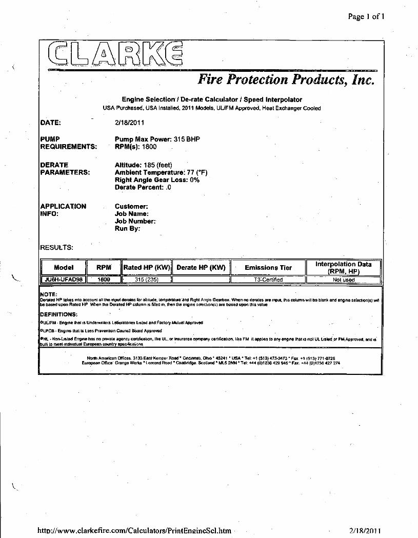
Page 1 of 1
Fire Protection Products, Inc. Engine Selection7 De-rate Calculator / Speed Interpolator
USA Purchased, USA Installed, 2011 Models, UL/FM Approved, Meat Exchanger Cooled
2/18/2011
Pump Max Power: 315 BMP RPM(s): 1800
Altitude: 185 (feet) Ambient Temperature: 77 (°F) Right Angle Gear Loss: 0% Derate Percent: .0
Customer: Job Name: Job Number: Run By:
RESULTS:
Model RPM Rated HP (KW) Derate HP (KW) Emissions Tier Interpolation Data (RPM, HP)
JU6H-UFAD98 1800 315(235) T3-Certified Nolused
NOTE: Derated HP lakes mid account all the mput derates Far altitude, temperature and Right Angle Gearbox. When no derates are input, this column will be blank and engine selection(s) will be based upon Rated HP When the Derated HP column is filled in. then Ihe engine selectionist are based upon this.value
DEFINITIONS: OUL7FM • Engme lhal is Underwriters Laboratones Listed snd Faclory Mutual Approved • '
OLPCB - Engine that is Loss Prevention Council Board Approved
•NL - Non-Listed Engine has no private agency certification, like UL, or insurance company certification, like FM It applies to any engine lhal is not UL listed or FM Approved, and is
budt to meet individual European country specficalions
North American Offices. 3133 East Kemper Road • Gncinnali. Ohio ' 45241 ' USA * Tel: +1 (513) 47S-3473" Fax. +1 (513) 771-0726 European Office GrangB Works' Lomond Road • Coatbridge. Scotland * ML5 2NN * Tel: +44 (0)1236 429 946' Fax: -44 (0)1236 427 274
DATE:
PUMP REQUIREMENTS:
DERATE PARAMETERS:
APPLICATION INFO:
hitTj://www.clarkefire.coWCalculators/PnntEnEineSel.htm 2/18/2011

Page 1 of 1
Customer:
Fire Protection Products, Inc. Exhaust Backpressure Calculator • Results
Calculations made 2/16/2011
Data input by:
Job Name: Input Data:
Job Number Engine Data: Piping Data: Silencer Data: Manufacturer Clarke Pipe Size: 5" Manufacturer Clarke USA Model: JU6H-UFAD98 #90" elbow or Y: Pipe Size (in): 5 RPM: 1760 Number 45° elbows: Model: C06545 HP:315 Number Tees:
Straight Pipe (Feet): 30 Application: Industrial Connection: 150# Flange
Exh Flow (CFM): 1400 Temperature (" F): 961 Max Backpressure (inches water): 30 Mln Backpressure (inches water): 0 Std. Exhaust Dla (In): 5
Output Data:
E N D IN -t£ " V J - E K D O U T
00
•a
o
5 25
E 63 1J !5 2( iO 500 1000 2000 4000 80
OCTAVE BAND CENTER FREQUENCY (Hz)
BACKPRESSURE CALCULATIONS (Inches water)
Exhaust Pipe Recommendation:
6:5
+ 8.0
14.5
30.0
Pipe
Silencer (see note 1)
Total
Maximum Allowable Backpressure
Result: Total Backpressure is lower than minimum
1) CAUTION Silencer BacKcessure is based upon a Clarka USA provided Silencer Actual Sterner Backpressure mil vary depending upon Ihe actual Silencer used (manufacturer sue. type and model) I' me total Backpressure from the p.pe. Silencer end onflee plate (if required) is dose lo the engine Maximum Allowed Backpressure, rt is highly recommended you obtain the actual Backpressure (for the engine exhaust flow given above) on the Sdeneer be.ng used end then confirm thai the Iota) Backpressure is sou under the Maximum ruTowad Backpressure ?) Schedule <*0 pipe used m calculations 3) All pipe sizes and lengths are in inches and feet *) WARNING' The total Backpressure is less than the engine permissible Backpressure In order to gel the maximum Backpressure above the engine permissible limit, you must flange one or more of the following: pipe site; pipe length; Silencer site, Silencer type.
North American Offices-
3133 East Kemper Roaa ' Cincfnnali. Ohio ' 15241 • USA* Tel »1 (513) 771-2200 ' Fax'+1 (513)771-0726
European Office. SranpeWorks * Lomond Road • Coatbrrdae. Scotland * MLS 2NN * Tel. +44 (011236 429 946 * Fax' *44 (0)1236 427 274
htto://www.clarkefirexom/Calculators/PrintExhaust.htiT) ? / i 8 / ? m i

Feagins, Rob (DEQ)
Sent: To: Cc: Subject: Attachments:
From: Gener Gotiangco [[email protected]] Tuesday, February 04, 2014 2:06 PM Feagins, Rob (DEQ) 'Sellers, Fred ([email protected])'; Babcock, Steven CPV Smyth - updated PSD Application transmittal CPV Smyth VA DEQ PSD Transmittal 02042014.pdf
Good afternoon Rob,
Please find the attached transmittal that address your comments to our January 31, 2014 CPV Smyth PSD Air Permit Application. This transmittal includes the amended Appendix A page 5 General Information and the amended Appendix C. The transmittal original is also being sent to you via hardcopy.
Thank you again for your timely review and these comments.
Feel free to advise should you have further questions or comments.
Regards,
Gener Gotiangco Competi t ive Power Ventures, Inc. 8403 Colesville Road Suite 915
Silver Spring, MD 20910 Office: (240) 723-2307 Cell: (301) 346-5738 F a x : ( 2 4 0 ) 7 2 3 - 2 3 3 9
This e-mail message and any attached files are.confidential and are intended solely for the use of the addressee(s) named above. If you are not the intended recipient or you have received this communication in error, please notify the sender immediately by reply e-mail.message andpermanently delete the original message.To reply to our email administrator directly, send an email to [email protected]
1

Compe t i t i ve Power Ventures, Inc.
February 4, 2014
Virginia Department of Environmental Quality Attention: Rob Feagins, Air Permit Manager Southwest Regional Office 355-A Deadmore Street Abingdon, Virginia 24210
RE: CPV Smyth Generation Company, LLC Prevention of Significant Deterioration Air Permit Application - updated
Dear Mr. Feagins,
In response to your February 3, 2014 communication requesting a correction and clarification to CPV Smyth's referenced Air Permit application, please find enclosed for your use and retention with the original submittal the following:
Appendix A to application, Page 5 of Form 7 updating the General Information with the correct entity and contact (1 sheet).
Appendix C Equipment Specifications and Vendor Performance Dat% revised to remove "Confidentiality" notation as the major equipment supplier, Alstom, has withdrawn its request to seek confidentiality for their emissions and performance information (23 sheets).
Should you have further questions or clarifications, please do not hesitate to contact me at your convenience.
Gener G. Gotiangco, P.E. ggOtiangco@,cpv.com 240-723-2307
ec: M. Kiss, VA DEQ (via email) F. Sellars, Tetra Tech (via e-mail) R. Burke, Competitive Power Ventures, Inc. (via e-mail)
Sincerely.
C P V COMPETITIVE POWER VENTURES, INC,
8403 COLE SVILLE ROAD SUITE 915 SILVER SPRING; MD 20910
T/240 7Z3-23O0 f l 240 723-2339 WWW.CPV.COM

CPV Smyth Generation Project PSD Air Permit Application
GENERAL INFORMATION
Person Completing Form: Gener Gotiangco Date: 01/27/2014
Registration Number:
Company and Division Name: CPV Smyth Generation Company, LLC FIN: 52-2306411
Mailing Address: 8403 Colesville Road, Suite 915 Silver Spring, MD 20910
Exact Source Location - Include Name of City (County) and Full Street Address or Directions: Atkins, VA Telephone Number: No. of Employees: Property Area at Site:
Person to Contact on Air Pollution Matters - Name and Title: Gener Gotiangco Vice President
Phone Number: (240) 723-2307 Person to Contact on Air Pollution Matters - Name and Title: Gener Gotiangco Vice President
Fax: (240) 723-2339 Person to Contact on Air Pollution Matters - Name and Title: Gener Gotiangco Vice President
Email: GGotianqco®!cpv.com Latitude and Longitude Coordinates OR UTM Coordinates of Facility:
Reason(s) for Submission (Check all that apply):
| | State Operating Permit This permit is applied for pursuant to provisions ofthe Virginia Administrative Code, 9 VAC 5 Chapter 80, Article 5 (SOP)
f x l New Source
| 1, Modification of a Source
| | Relocation of a Source
| | Amendment to a Permit Dated
Amendment Type:
This permit is applied for pursuant to the following provisions of the Virginia Administrative Code:
9 VAC 5 Chapter 80, Article 6 (Minor Sources) 9 VAC 5 Chapter 80, Article 8 (PSD Major Sources) 9 VAC 5 Chapter 80, Article 9 (Non-Attainment Major Sources)
Permit Type: Q SOP (Art. 5) Q NSR (Art. 6, 8, 9)
Administrative Amendment Minor Amendment Significant Amendment
This amendment is requested pursuant to the provisions of: 9 VAC 5-80-970 (Art. 5 Adm.) | | 9 VAC 5-80-1935 (Art. 8 Adm 9 VAC 5-80-980 (Art: 5 Minor) 9 VAC 5-80-990 (Art. 5 Sig.)
9 VAC 5^80-1945 (Art. 8 Minor) 9 VAC 5-80-1955 (Art. 8 Sig.)
9 VAC 5-80-1270 (Art. 6 Adm ) 9 VAC 5-80-1280 (Art. 6 Minor) 9 VAC 5-80-1290 (Art. 6 Sig.)
9 VAC 5-80-2210 (Art. 9 Adm ) 9 VAC 5-80-2220 (Art. 9 Minor) 9 VAC 5-80-2230 (Art. 9 Sig:)
| | Other (specify):
Explanation of Permit Request (attach documents if needed):
Application for a proposed combined cycle electric generating facility required to obtain a Major NSR Air Permit subject to Prevention of Significant Deterioration requirements. This document contains a detailed description of the project and potential emission estimates for all pollutants.
Form 7 -April 8, 2013 Page 5

CPV Smyth Generation Project PSD Air Permit Application
APPENDIX G
Equipment Specifications and Vendor Performance Data

ALSTOM 01/06/14
ALSTOM Smyth County (USA): KA24-2 (2011) MS, ACC, SF Rev E Performance Summary 1AHV424657
1 The corrections from 'Gross Output/Efficiency' to 'Net Output / Efficiency' reflects current aux. consumption/losses for Alstom equipment only.
2 Values for Information only. 3 Gas turbine output does not include the OTC heat rejection energy.
4 Ambient Pressure: 13.56 psia 5 Air Cooled Condenser 6 CO & SCR Catalyst considered for HRSG pressure drop calculations and stack emissions 7 PM10/PM2.5 measurements per EPA Method 201/a + 202 8 Particulate Matter exhaust emissions are the net emission values, i.e. the emission contribution above those pre-existing
in theambient air. Alstom therefore reserves the right to correct for the pre-existing ambient air quality if required.
9 Particulate matter emissions are often below the detection limits of most of the measuring systems. Therefore if no particulate matter is detected within maximum 4 hours of measurement, the particulate emission is deemed to have been fulfilled:
10 Particulate Matter emission limits are valid for steady state gas turbine operatingconditions and are based on a three-hour average.
11 Prior to any Particulate Matter measurements, the gas turbine must be in operation continuously for at least 8 hours at or near base load. Gasiturbine inlet and exhaust system are assumed to be fully commissioned and clean condition before the measurement.
12 Particulate Matter measurements may have to be repeated in order to fullfil the particulate emissions.
13 All values are based on the following fuel composition:
Constituent Volume (%)
Nitrogen 0.664
Carbon Dioxide 0.548 Methane 962274
Ethane 2.175
Propane 0.264
Butane 0.08 Pentane 0.013
Hexane 0.016
Heptane 0.012
Octane 0.0006
LHV (Btu/lb) 20885
HHV (Btu/lb) 23156
Sulfur Content is 0.5 grains/100 SCF Fuel 14 The performance summary is based on the following case descriptions:
CASE1 2x100%, PO, 90F,.50% RH, EC+HF=ON, SF=ON
CASE 2 2x100%, PO, 90F, 50% RH, EC+HF=ON, SF=OFF
CASE 3 2x75%, PO, 90F, 50% RH, EC=OFF, HF=OFF, SF=OFF
CASE 4 2x50%, PO, 90F, 50% RH, EC=OFF, HF=OFF, SF=OFF
CASE 5 2xLLOC%,90F,50%RH, EC=OFF, HF=OFF, SF=OFF
CASE 6 2x100%, PO, 100F, 30% RH, EC+H F=ON, SF=ON
CASE 7 2x100%, PO, 100F, 30% RH,iEC+HF=ON, SF=OFF
CASE 8 2x75%, PO, 100F, 30% RH, EC=OFF, HF=OFF, SF=OFF
CASE 9 2x50%, PO, 100F, 30% RH, EC=0FF, HF=0FF, SF=OFF
CASE 10 2xLLOC%, 100F, 30% RH, EC=OFF, HF=OFF, SF=OFF
CASE 11 2x100%, PO, 59F, 60% RH, EC=OFF, HF=OFE, SF=OFF
CASE 12 2x75%, PO, 59F, 60% RH, EC=OFF, HF=OFF, SF=OFF
CASE 13 2x50%, PO, 59F,,60% RH, EC=OFF, HF=OFF, SF=OFF
CASE 14 2xLLOC%, 59F; 60% RH, EC=OFF, HF=OFF, SF=OFF
CASE 15 2x100%, PO, -10F, 60% RH, EC=OFF, HF=OFF, APH=ON, SF=OFF
CASE 16 2x75%, PO, -10F, 60% RH, EC=OFF, HF=OFF, APH=ON, SF=OFF
l'-of 4
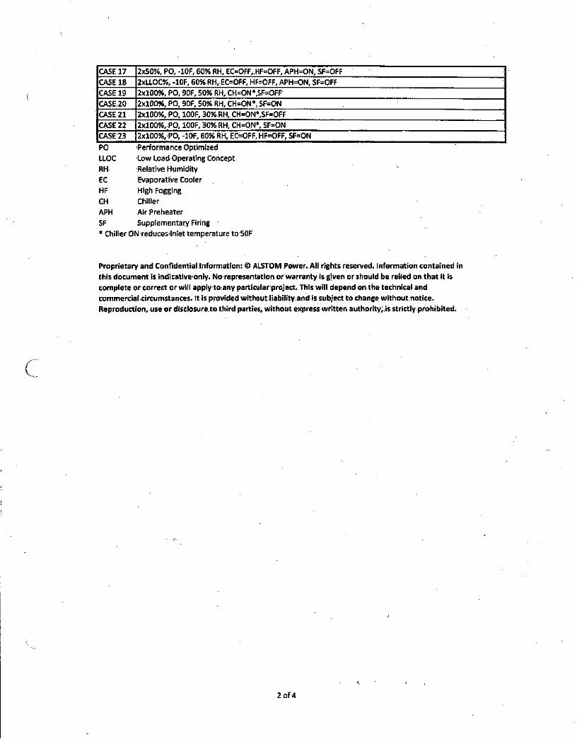
CASE 17 2x50%, PO,-10F, 60% RH, EC=OFF,;HF=OFF, APH=ON, SF=OFF CASE 18 2xLLOC%, -10F, 60% RH,,EC=OFF, HF=OFF, APH=ON, SF=OFF ;
CASE 19 2x100%, PO, 90F, 50% RH, CH=ON*,SF=OFF' CASE20 2x100%, PO.90F, 50% RH,CH=ON*SF=ON CASE 21 2x100%, PO, 100F, 30% RH, CH=ON*,SF=OFF
CASE-22 2x100%, PO, 100F, 30% RH; CH=ON*, SF=ON CASE 23 2xl00%/PO, -10F, 60% RH, EC=OFF, HF=OFF, SF=ON
PO Performance Optimized LLOC Low Load Operating Concept RH Relative Humidity EC Evaporative Cooler HF High Fogging CH Chiller
APH AirPreheater
SF Supplementary Firing * Chiller ONreducesiinlet temperature to 50F
Proprietary and Confidential Information: © ALSTOM Power. All rights reserved. Information contained in this document is indicativeonly. No representation or warranty Is given or should be relied on that it is complete or correct or will apply to any particular project. This will depend on the technical and commercial circumstances. It is provided without liability and is subject to change without notice. Reproduction, use or disclosure to third parties, without express written authority, is strictly prohibited.
2 o f 4

]%, PO, 90F, 2x100%, PO, 90F, 2x75%, PO, 90F, 2x50%, PO, 90F, 2xLLOC%, 90. 2x100%, PO, 100F, 2x100%, PO, 100F, 2x75%, PO, 100F, 2x50%, PO, 100F, 2xLL( OOF. 30% 2x100%, P( SO* RH, EC+HF=ON, 50% RH, EC+HF=ON, 50% RH, ECOFF, 50% RH, EC=0FF, RH, EC=OFF, 30% RH, EG+HF=ON, 30% RH, EC+HF=ON, 30% RH, EC=OFF, 30% RH, EC=OFF, RH, tC=OFF, 60%RH, EC
SF=ON SF=OFF HF=OFF, SF=0FF HF=0FF, SFOFF HF=0FF, SF=OFF SF=ON SF=OFF HF=OFF, SFOFF HF=OFF, SF=OFF HF=OFF, SF=OFF HF=OFF, SI *F 90.0 90.0 90.0 90.0 90.0 100.0 100.0 100.0 100.0 100.0 59.0
% 50.0 50.0 50.0 50.0 50.0 30.0 30.0 30.0 30.0 30.0 60.0
- 2 2 2 2 2 2 2 2 2 2 2
- ON ON OFF OFF OFF ON ON OFF OFF OFF OFF
- ON ON OFF OFF OFF ON ON OFF OFF OFF OFF ON OFF OFF OFF OFF ON . OFF OFF OFF OFF OFF
MW 690.6 591.2 408.4 291.6 60.1 681.0 583.0 386.5 276.4 56.8 602.C
% 54.4 56.7 55.9 52.7 28.3 53.7 56.1 54.9 51.6 27.3 57.9 Btu/kWh 6276 6017 6100 6476 12061 6350 6085 6211 6614 12509 5897
MW 689.1 589.7 406.9 290.1 58.6 679.5 5815 385.0 274.9 553 600.!
% 54.25 56.56 55.73 52.42 27.58 53.62 55.93 54.72 51.31 26.56 57.75 Btu/kWh 6290 6032 6122 6509 12370 6364 6100 6235 6650 12848 5912
100.0 100.0 75.0 50.0 LLOC 100.0 100.0 75.0 50.0 LLOC 100.C MW 193.50 193.50 124.41 82.94 7.57 192.71 192.71 117.48 78.32 6.75 192.6
MMBtu/hr 1778.74 1778.74 1245.42 944.31 362.65 1773.57 1773.57 1200.39 914.06 355.43 1774.? MMBtu/hr 1972 1972 1381 1047 402 1966 1966 1331 1013 394 1968
•F 1136.7 1136.7 1202.0 1202.0 929.4 1136.5 11365 1202.0 1202.0 936.8 1119. Ib/hr 3509150 3509150 2562907 2096519 1443985 3506293 3506293 2511261 2063268 1428654 36558-
MWth 19.66 19.66 13.46 8.11 3.81 19.85 19.85 14.22 8.81 3.91 25.7;
MMBtu/hr 389 0 0 0 0 389 0 0 0 0 0 MMBtu/hr 431 0 0 0 0 431 0 0 0 0 0
°F 177.0 195.8 175.1 170.4 193.8 181.0 202.5 178.7 174.2 195.6 187J Ib/hr 3527757.9 3509150.3 2562907.2 2096519.0 1443984.8 3524900.5 3506292.9 2511261.0 2063268.4 1428654.1 365583
inH20 15.4 15.4 8.4 5.6 2.4 15.3 15.3 8.1 SS 2.3 16.5
MW 303.6 204.2 159.5 125.8 45.0 295.6 197.5 151.6 . 119.8 43.3 216.( psia 2.259 1.679 1.412 _ 1.246 1.088 2^871 2.152 1.813 1.618 1.267 1.08!
vol% 70.71% 71.3594 73.04% 73.26% 74.47% 70.8494 71.48% 73.45% 73.66% 74.85% 74.15' vol% 9.05% 10.92% 11.65% 12.28% 15.84% 9.1094 10.97% 11.87% 12.49% 15.97% 11.91' vol% 14.34% 12.69% 10.38% 9.83% 6.68% 14.1794 12.51% 9.80% 9.25% 6.17% 8.98) vol% 5.05% 4.19% 4.05% 3.76% • 2.13% 5.0594 4.18% 3.99% 3.71% 2.11% 4.07) vol% 0.85% 0.85% 0.87% 0.88% 0.89% 0.8594 0.85% 0.88% 0.88% 0.90% 0.89)
ppmvd @ 15% 0 2 2.0 2.0 2.0 2.0 2.0 2.0 2.0 2.0 2.0 2.0 2.0 Ib/hr 10.6 8.7 6.1 4.6 1.8 10.6 8.7 5.9 A3 1.7 8.7
vol% 5.1% 4.2% 4.1% 3.8% 2.1% 5.096 4.2% 4.0% 3.7% 2.1% 4.1%
Ib/hr 281544 231370 162064 122953 47518 280876 230702 156227 119034 46580 23095
ppmvd @ 15% 0 2 2.0 2.0 2.0 2.0 2.0 2.0 2.0 2.0 2.0 2.0 2.0
Ib/hr 17.4 14.3 10.0 7.6 2.9 17.4 14.3 9.7 7.4 2.9 14.3
ppmvd @ 15% 0 2 2.0 1.0 1.0 1.0 2.0 2.0 1.0 1.0 1.0 2.0 1.0 Ib/hr 6.1 2.5 1.7 1.3 1.0 6.1 2.5 1.7 1.3 1.0 . 2.5 Ib/hr 3.2 2.6 1.8 1.4 0.5 3,2 2.6 1,8 1,3 0.5 2.6
Ib/hr 2.0 1.7 1.2 0.9 0.3 20 1.7 1.1 0.9 03 1,7
lb/hr 6.4 5.2 6.1 4.6 1.8 6.4 5.2 5.9 4.5 1.7 5.2 Ib/hr 5.5 1.8 2.9 3.6 0.3 5.5 1.7 2.9 33 0.3 1.7 Ib/hr 11.9 7.0 9.0 8.2 2.1 11.9 7.0 8.7 8.0 2.1 7.0
ppmvd @ 15% 0 2 5.0 5.0 5.0 5.0 5.0 5.0 5.0 5.0 5.0 5.0 5.0 Ib/hr 16.1 13.2 9.3 7.0 2.7 16.1 13.2 8.9 6.8 2.6 13.2
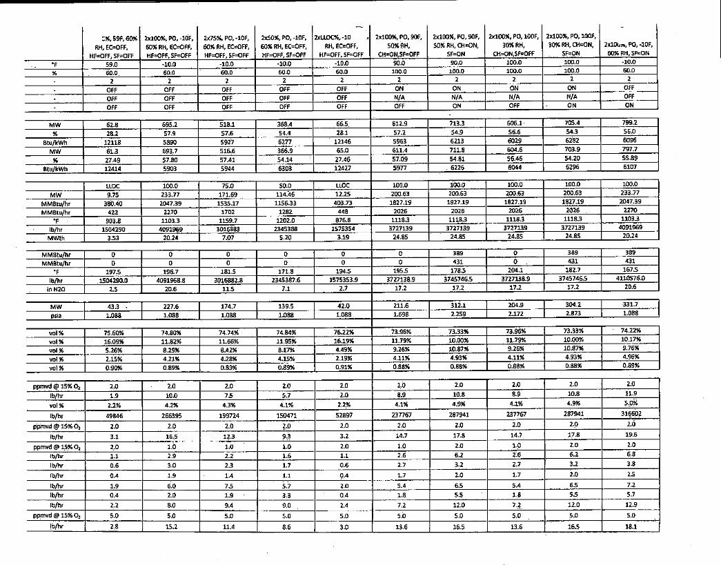
:%, S9F, 60% RH, EC=OFF,
HF=OFF, SF=OFF
2x100%, P0,-10F, 60% RH, F.COFF, HF=OFF,SF=0FF
2x75%, PO, -10F, 60% RH, EC=OFF, HF=OFF, SF=OFF
2x50%, PO, -10F, 60% RH, EC=OFF, HF=OFF, SF=OFF
2xLLOC%,-10 RH, EC=OFF,
HF=OFF, SF=OFF
2x100%, PO, 90F,
50% RH, CH=ON,SF=OFF
2x100%, PO, 90F, 50% RH, CH=ON,
SF=ON
2x10094, PO, 100F, 3094 RH,
CH=ON,SF=OFF
2x10054, PO, 100F, 3094 RH, CH=ON,
SFrON 2xl0u», PO, -10F, 6054 RH, SF=ON
•F 59.0 -10.0 -10.0 -10.0 -10.0 90.0 90.0 100.0 100.0 -10.0
% 60.0. 60.0 60.0 60.0 60.0 100.0 100.0 100.0 100.0 60.0
2 2 2 2 2 2 2 2 2 2
OFF OFF OFF OFF OFF ON ON ON ON OFF
OFF OFF OFF OFF OFF N/A N/A N/A N/A OFF
OFF OFF OFF OFF OFF OFF ON OFF ON ON
MW 62.8 695.2 518.1 368.4 66.5. 612.9 713.3 606.1 705.4 799.2
% 28.2 57.9 57.6 54.4 Z8.1 57.2 54.9 56.6 54.3 56.0
Btu/kWh 12118 5890 5927 6277 12146 5963 6213 6029 6282 6096
MW 61.3 693.7 516.6 366.9 65.0 611.4 711.8 604.6 703.9 797.7
% 27.49 57.80 57.41 54.14 27.46 57.09 54.81 56.46 54.20 55.89
Btu/kWh 12414 5903 5944 6303 12427 5977 . 6226 6044 6296 6107
LLOC 100.0 75.0 50.0 LLOC 100.0 100.0 100.0 100.0 100.0
MW 9.75 233.77 171.69 114.46 12.25 200.63 200.63 200.63 200.63 233.77
MMBtu/hr 380.40 2047.39 1535.17 1156.33 403.73 1827.19 1827.19 1827.19 1827.19 2047.39
MMBtu/hr 422 2270 1702 1282 448 2026 2026 2026 2026 2270
•F 903.8 1103.3 1159.7 1202.0 876.8 1118.3 1118.3 1118.3 1118.3 1103.3
Ib/hr 1504290 4091969 3016883 2345388 1575354 3727139 3727139 3727139 3727139 4091969
MWth 3.53 20.24 7.07 5.20 3.19 24.85 24.85 24.85 24.85 20.24
MMBtu/hr 0 0 0 0 0 0 389 0 389 389
MMBtu/hr 0 a 0 0 0 0 431 0 . 431 431
•F 197.5 196.7 181.5 171.8 194.5 195.5 178.5 204.1 182.7 167.5
Ib/hr 1504290.0 4091968.8 3016882.8 2345387.6 1575353.9 3727138.9 3745746.5 3727138.9 3745746.5 4110576.0
in H20 2.5 20.6 11.5 7.1 2.7 17.2 17.2 17.2 17.2 20.6
MW 43.3 • 227.6 174.7 139.5 42.0 211.6 312.1 204.9 304.2 331.7
psia 1.088 1.088 1.088 1.088 1.088 1.698 2.259 2.172 2.873 1.088
vol% 75.60% 74.80% 74.74% 74.84% 76.2254 73.96% 73.3394 73.9694 73.3394 ' 74.22%
vol% 16.09% 11.82% 11.66% 11.95% 16.19% 11.79% 10.0094 11.7994 10.0054 10.17%
vol% 5.26% 8.29% 8.42% 8.17% 4.49% 9.26% 10.8794 9.2694 10.8794 9.76%
vol% 2.15% 4.21% 4.28% 4.15% 2.19% 4.11% 4.9394 4.1194 4.9354 4.96%
vol% 0.90% 0.89% 0.89% 0.89% 0.91% 0.88% 0.8894 0.8894 0.8894 0.89%
ppmvd @ 15% O2 2.0 2.0 2.0 2.0 2,0 2,0 2.0 2.0 2.0 2.0
Ib/hr 1.9 10.0 75 5.7 2.0 8.9 10.8 8.9 10.8 11.9
vol% 2.2% 4.2% 4.3% 4.1% 2,2% 4.1% 4.994 4.194 4.954 5.0%
Ib/hr 49846 266395 199724 150471 52897 237767 287941 237767 287941 316602
ppmvd <§> 15% O, 2.0 2.0 2.0 2.0 2.0 2.0 2.0 2.0 2.0 2.6
Ib/hr 3.1 16,5 12.3 9.3 3.2 14.7 17.8 14.7 !7.8 19.6
ppmvd @ 15% 0 2 2.0 10 1.0 1.0 2.0 1.0 2.0 1,0 2.0 2.0
Ib/hr 1.1 2.9 2.2 1.6 1.1 2.6 6.2 2.6 6.2 6,8
Ib/hr 0.6 3.0 23 1.7 0.6 2.7 3.2 2.7 3.2 3.8
Ib/hr 0.4 1.9 1.4 1.1 0.4 1.7 2.0 1.7 2.0 25
Ib/hr 1.9 6.0 7.5 5.7 2.0 5.4 6.5 5.4 6.5 7.2
Ib/hr 0.4 2.0 1.9 3.3 0.4 1.8 5.5 1.8 5.5 5.7
Ib/hr 2,2 8.0 9.4 9.0 2.4 7.2 12,0 7,2 12.0 12.9
ppmvd @ 15% 0; 5.0 5.0 5.0 5.0 5.0 5.0 5.0 5,0 5.0 5.0
Ib/hr 2,8 15.2 11.4 8.6 3.0 13.6 16.5 13.6 16.5 18.1

Plant Start-Up and Shutdown Emissions KA24-2 Smyth County
Projects and Customer's Information:
KA24-2 (2011)
Space for Stamping (Review and Validation status)
Gross checked Department Name Date Signature
Revision History Rev. Revision Date Created by Checked by Approved by Brief Description
Description current Revision
Main Contractor
ALSTON 1 Alstom (Switzerland L t d . , Brown Boveri Strasse 7, CH 5401-Baden
Replaces Customer Code ALSTOM Document Code
Responsible dept. Created by Checked by GASNAM-US E. Brown M. Feeney
Approved by Format C. Dougherty A4
Originator
ALSTOM POWER GAS BUSINESS
Document Type Design Concept
Document Status Electronically Released
Originator
ALSTOM POWER GAS BUSINESS
Title, Subtitle Plant Start-Up and Shutdown Emissions
Identification number 1AHV423411
Originator
ALSTOM POWER GAS BUSINESS
Title, Subtitle Plant Start-Up and Shutdown Emissions Rev. ;' Date Lang; Sheet
A 12/06/2013 en 1/7
©ALSTOM 2013. All rights reserved. Please consider the environment before printing this document.

Table of Contents:
1. Introduction »»3
2. Fuel Gas Composition 3
3. Startup Emissions Data 4
3.1. Normal Hot Start-Up to Compliance (After Approx. 8 hours standstill) .......4
3.2: Fast Hot Start-Up to Compliance (After Approx. 8 hours standstill), 4
3.3. Non-Spinning Reserve Start-up to Compliance (After Approx. 8 hours standstill). 5
3.4.- Normal Warm Start-Up to Compliance (After Approx. 60 hours standstill).,...,......,............ 5
3:5 NormaliCold Start-Up to Compliance (After Approx. 200 hours standstill) 6
3:6.. Shutdown: Minimum Emissions Load to Flameout.... 6
3.7. Compliance to Low Load Operation 1
3.8. Low Load Operation to Compliance 7
Originator Identification number Rev. Date Lang. Sheet
ALSTOM POWER 1AHV423411 rr rnnlainnii Hntnin 'Drtrtrfu-tl irtifWl iicn fiptf Ifimi I* A in ifrtinj MfirilAV <•
A f v n t n
12/6/2013 -•s w j r r f l t m a u l h n r i r u i t R t r i f t t t v
en mnViiWJrett
2/7

1. In t roduct ion
This document gives an indication ofthe CCPP exhaust emission per GT during cold, warm, and hot startup conditions as well as the shutdown and low load transient operation for the Smyth County project. The start-up emissions consist from GT ignition to time when plant reaches full compliance (2 ppmvd @ 15% 02 CO and 2 ppmvd @ 15% 02 NOx), i:e., when GO & SCR catalyst are fully operational and assumes HRSG purge credit as well as evacuation of the condenser as stated in the tables provided. Start-up emissions are based on both units starting at the same time. All figures for plant start-up emissions do include estimated CO and SCR reduction.
2. Fuel Gas Compos i t i on
For the stated emissions, sulfur content considered in the fuel is 0.5 grains/1 OOscf with the below fuel chemical composition.
Constituent Volume (%)
Methane CH4 96.2274
Ethane C2H6 2.175
Propane C3H8 0.264
Butane C4H10 0.08
PentaneC5H12 I 0.013
Hexanes C6H14 0.016
Heptane C7H16 0.012
Octane C8H18 0,0006
Nitrogen N2 0.664
Carbon Dioxide C02 0.548
TOTAL 100
LHV (Btu/lb) 20885
HHV (Btu/lb) 23156
Originator
ALSTOM POWER Identification number 1AHV423411
Rev. A
Date 12/6/2013
Lang, en
Sheet 3/7

3. Star tup Emiss ions Data
3.1. Normal Hot Start-Up t o Compliance (After Approx. 8 hours standstill).
AmbientTemperature -10°F 59°F 90°F 100°F ;
Duration < min from ign '60 56 54 53
Nox as N02 lb/event 47 44 43 43
GO lb/event 47 36 35 35
VOC as CH4 lb/event 38.8 28 25.7 26.3
PM10/2.5 Total Ib/eyent & 1 6.3 6.5 6.2
H2S04 lb/event 1.0 0.8 0.8; 0.7
Heat Consumption MMBTU HHV 856 717 657 628
Worst-Case estimated 1-hr average exhaust flow - 1840 klb/hr on the hot day
Worst-Case estimated 1-hr average stack temperature - 1I50F
3.2. Fast Hot Start-Up to Compliance (After Approx. 8 hours standstill).
Ambient Temperature -10°F 5.9'F 90°F 100°F
Condenser Evacuation Prior to Start Initiation
Duration min from ign 42 40 39 38
Nox as N02 lb/event 50 48 47 47
CO lb/event 25 20 20 20
VOC as CH4 lb/event 17 12 11 11
PM10/2.5 Total lb/event 6.9 5.0 6.1 4.8
H2S04 lb/event 0.8 0.7 0.7 0.7
Heat Consumption MMBTU1 HHV 815 730 694 676
Worst-Case estimated 1-hr average exhaust flow = 2150 klb/hr on the hot day
Worst-rCase estimated 1-hr average stack temperature = 150F
Originator Identification number Rev: Date Lang Sheet
ALSTOM POWER 1AHV423411 A 12/6/2013 en 4/7 O ALSTOM 2013. We reserve all righls In this document and In the information conlalncd hoioin. Ro(xodu«t!on; use. discfofluro lo thiid parties without express wirton authority is strictly prohibited.
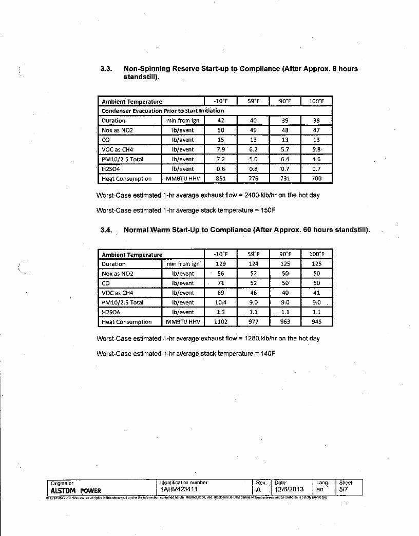
3.3. Non-Spinning Reserve Start-up to Compliance (After Approx. 8 hours standstill).
Ambient Temperature -10"F 59-F 9CTF 100° F
Condenser Evacuation Prior to Start Init iation
Duration min from ign 42 40 39 38
Noxas N02 lb/event 50 49 48 47
CO lb/event 15 13 13 13
VOC as CH4 lb/event 7.9 6.2 5.7 5.8
PM10/2.5 Total lb/event 7,2 5.0 6.4 4.6
H2S04 lb/event 0.8 0.8 0.7 0.7
Heat Consumption MMBTU HHV 851 776 731 700
Worst-Case estimated 1-hr average exhaust flow = 2400 klb/hr on the hot day
Worst-Case estimated 1-hr average stack temperature = 150F
3.4. Normal Warm Start-Up to Compliance (After Approx. 60 hours standstill).
Ambient Temperature -10°F : 59°F 90°F 100°F
Duration min from ign 129 124 125 125
Nox as N02 lb/event 56 52 5.0 50
CO lb/event 71 52 50 50
VOCasCH4 lb/event 69 46 40 41
PM10/2.5 Total ib/event 10:4 ; 9.0 9:0 9:0
H2S04 lb/event 1.3 1.1 1.1 1.1
Heat Consumption MMBTU HHV . 1102 977 963 945
Worst-Case estimated 1-hr average exhaust flow = 1280 klb/hr on the hot day
Worst-Case estimated 1-hr average stack ternperature = 140F
Originator Identification number Rev. : Date Lang. Sheet
ALSTOM POWER 1AHV423411 A 12/6/2013 en 5/7 © ALSTOM 2013. We reserve all rights in (his document and In the inlonnabou contained heroin. Reproduction, use, disclosure lo third parties without cxrwees written authority is strictly prohibited.
, X

3.5. Normal Cold Start-Up to Compliance (After Approx. 200 hours standstill)
Ambient Temperature -10°F 59°F ' 90°F 100°F
Duration min from ign 183 178 179 178
Nox as N02 lb/event 61 57 55 54
CO lb/event 77 56 53 53
VOC as CH4 lb/event 73 48 42 44
PM10/2.5 Total lb/event 14 12 12 12
H2S04 lb/event 1:7 1.6 1.6 1.6
Heat Consumption MMBTU HHV 1502 1354 1324 1299
Worst-Case estimated 1-hr average^ exhaust flow = 1280 klb/hr on the hot day
Worst-Case estimated 1-hr average stack temperature = 120F
3.6. Shutdown: Minimum Emissions Load to Flameout
Ambient Temperature -10°F 59"F 90°F 100"F
Duration min 13 11 9.7 9.2
Nox as N02 lb/event 4.6 3.5 2.9 2.7
GO lb/event 17 10 8.9 8.9
VOC as CH4 lb/event 25 15 12 13
PM10/2.5 Total lb/event 1.9 1.4 1.2 1.2
H2S04 lb/event 0.2 0.2 0.1 0.1
Heat Consumption MMBTU HHV 179 132 112 103
Worst-Case estimated 1-hr average exhaust flow = 1640 klb/hr on the hot day
Worst-Case estimated; 1-hr average stack temperature = 150F
Originator Identification number Rev. Date Lang. Sheet
ALSTOM POWER 1AHV4234T1 A 12/6/2013 en 6/7 O ALSTOM 2013, We reserve nit iiohts In this dunument and in lire inlosmaUon coitUiined huiein. Rcproductiw.'uso, disclosure to Ihi'id parties without express written aullioriry is strictly prohibited.

3.7. Compliance to Low Load Operation
Note: During Low Load Operation Emissions are in compliance
Ambient Temperature -10°F 59°F 90°F 100"F
Duration min 12 9.9 8.8 8.3
Nox as N02 lb/event 1.4 1.1 0.9 0.9
CO lb/event 17 10 8.7 8.7
VOC as CH4 lb/event 24 15 11 13
PMlO/2,5 Total lb/event 1.8 1.3 1.2 1.1
H2S04 lb/event 0.2 0.2 0.1 )o:i Heat Consumption MMBTU HHV 168 125 106 ' 9 8 3
Worst-Case estimated 1-hr average exhaust flow = 1660 klb/hr on the hot day
WorsfcCase estimated 1-hr average stack temperature = 150F
3.8. Low Load Operation to Compliance
Note: During Low Load Operation Emissions are in compliance.
Ambient Temperature -10°F 59°F 90°F 100°F
Duration min 12 9.9 8 8 8.3
Noxas N02 lb/event 1.5 1.1 1:0 0.9
GO lb/event 15 10 8:4 8.4
VOC as CH4 lb/event 24 15 11 13
PM 10/2.5 Total lb/event 1.9 1 3 1.2 1.1
H2S04 lb/event 0.2 0.2 0.1 0.1
Heat Consumption MMBTU HHV 168 125 106 98.3
Worst-Case estimated 1 -hr average exhaust flow = 1660 klb/hr on the hot day
Worst-Case estimated 1-hr average stack temperature = 150F
Originator Identification number Rev. Date Lang. Sheet
ALSTOM POWER 1AHV423411 A : 12/6/2013 en III Q ALSTOM 2013. We roservo oil rights in this document and in the Intomiation contained hotein. Reproduction, use, disclosure to ihitd parties without express written authority is strictly prohibited.

Industry & Energy Associates Revision 2
1.0 XNTROD'UCTIOI CB Nebraska Boiler & CB Natcom form the engineered boiler/burner division of the Cleaver-Brooks family of companies. We are committed to offering integrated boiler/burner solutions to the industry. This group of companies has been in this business for more than 80 years and continues to enjoy a large percentage of the market share. We maintain our leadership in the industrial watertube market by offering innovative solutions and a true single-source responsibility to our customers for boilers, burners, controls & auxiliary equipment. This commitment to overall system design ensures that your equipment operates efficiently and lasts for years to come.
For your unique application, we are offering a packaged solution with the following design features:
1.1 OUTLET STEAM CONDITIONS: Capacity: Operating Pressure: Steam Temperature.: Steam Quality:
77000 LB/HR H 200 PSIG (at exit of non-return valve) » Saturated at 387 °F 99.5% dry steam *
1.2 BOILER DESIGN: Type-Model: Vessel Design Pressure:
D-Type Industrial Watertube IMB-300D-70 250 psig
1.3 BURNER DESIGN: Type: Main Fuel: Emissions:
Ultra Low-NOx Register Natural Gas 9 PPM Nox
1.4 ECONOMIZER DESIGN: Type: Arrangement: Design Pressure: Inlet Feedwater Temp:
Rectangular Finned-Tube Vertical Gas Flow; Counter-Current Water Flow 30O psig 228°F
1.5 STACK DESIGN: Type: Diameter (at exit): Height (from grade):
Freestanding 78" 125 ft
6940 Cornhusker Hwy. o Lincoln, NE 68507 o Tel: (402)434-2000 O Fax (402)434-2064 o www.neboiler.com
NO. 24679-N Page 3 10-22-2009

Industry & Energy Associates Revision 2
3.0 BOILER DESIGN DATA : Boiler Dimensions: Units Height to Main Steam Outlet 14 Ft 7 I n FT Overall Width of Unit 11 Ft 7.5 In FT Overall Length of Unit* 25.33 Ft. FT *Add approximately 6-8 ft length for burner. Weight of Unit (Dry) 80,249.49 LBS Weight of Unit (Wet) 102,381.53 LBS
VS&iiacMMr&afy-Mitome: Units Furnace Volume 1,379 FT3 Furnace Projected Area 819 FT2
: Evaporator Area 4,277 FT2 Total Area 5,096 FT2 Economizer Area 13,317 FT2 Superheater Area - FT2
; Tubing Data: ^ j 3 / / . h ^ : ^ ^ ; ' : : C V f ^ W ' " - ' ^ feoAU.hitsf;f:^-vi Tube OD 2.0 IN Tube Wall Thickness - Furnace Section 0.105 IN Tube Wall Thickness - Convection Section 0.105 IN Tube Material SA178A Corrosion Allowance NA IN Steam Drum: Units Inside Drum Diameter: 42 In IN Drum Length 25.33 Ft. Seam/Seam FT Drum Material: SA516 Grade 70 Corrosion Allowance: NA IN 'Wate r lOmm: ! : Units Drum Diameter: 24 In IN Drum Length 25.33 Ft. Seam/Seam FT Drum Material: SA106 Grade B Corrosion Allowance: NA IN Standard Drum Connect ions: :('•'•.', ::;v:;<^anti'tvi- Y^TvperiC':' Main Steam Outlet: One Flanged Safety Valves: Per ASME Code Flanged Feedwater Inlet: One Flanged Bottom Drum Blowoff: Two Flanged Water Column: Two Threaded
(NPT) Feedwater Regulator: Two Flanqed Vent: One NPT Continuous Slowdown: One NPT Chemical Feed: One NPT Sootblower: Two Flanqed Auxiliary L.W. Cutouts: One NPT
*The above information is preliminary and shall be confirmed at time of engineering submittal.
6940 Cornhusker Hwy. O Lincoln, NE 68507 0 Tel: (402)434-2000 O Fax (402)434-2064 o www.neboiler.com
NO. 24679-N Page 12 10-22-2009

Industry & Energy Associates Revision 2
4.0 BOILER PERFORMANCE DATA Fuel: Natural Gas
Boiler load - °/o 1 0 0 % ympj&mha : % : # O j # v % . # 2 5 M A ^ Units Steam Flow - « 77,000 57,750 38,500 19,250 Lb/Hr Steam Pressure - Operating - « 200.0 200.0 200.0 200.0 PSIG Steam Temperature - « 387.0 387.0 387.0 387.0 °F Fuel Input (HHV) 92.4 69 .1 46.0 23.2 MMBTU/Hr Ambient Air Temperature 80.0 80.0 80.0 80.0 °F Relative Humidity 60 60 60 60 % Excess Air 25 25 25 25 % Flue Gas Recirculation 25 25 25 25 % Steam Output Duty 77 58 39 19 MMBTU/hr Heat Release Rate 67,012 50,097 33,366 16,805 BTU/FT3-Hr Heat Release Rate 112,882 84 ,389 56,204 28,308 BTU/FT2-Hr Deaerator Pegging Steam - - - - Lb/Hr Feed Water Temperature 227 227 227 227 °F Water Temp. Leaving Economizer 321 309 297 288 ±10°F Blow Down 1.0 1.0 1.0 1.0 % Boiler Gas Exit Temperature 543 498 451 409 ±10°F Economizer Gas Exit Temp. 299 282 266 251 ±10°F
Air Flow 84,454 63,137 42,050 21,179 Lb/Hr Flue Gas to Stack 88,692 66,305 44,160 22 ,241 Lb/Hr Flue Gas Including FGR 110,865 82 ,881 55,200 27,802 Lb/Hr Fuel Flow 4,237 3,167 2,109 1,062 Lb/Hr Flue Gas Losses/Ef f ic iency-% Dry Gas Loss 4.5 4.2 3.8 3.5 % Air Moisture Loss 0.1 0.1 0.1 0 .1 % Fuel Moisture Loss 10.6 10.6 10.5 10.4 % Casing Loss 0.5 0.7 1.0 2.0 % Margin 0.5 0.5 0.5 0:5 % Efficiency - LHV 92.8 93 .1 93.2 92.5 % Efficiency - HHV - n 83.7 84.0 84 .1 83.5 % Total Pressure Drop Including Economizer 9.46 5.30 2.35 0.56 IN WG Products of Combustion - C02 7.7 7.7 7.7 7.7 %
- H20 16.9 16.9 16.9 16.9 % -N2 71.7 71.7 71.7 71.7 % -02 3.8 3.8 3.8 3.8 % -S02 - - - - %
GAS- % volume l:';v:4\^::: r-zqNGMV/'
•••' - " ' methane 90.00 ethane 5.00 nitrogen 5.00
LHV-Btu/tb 19,687 HHV-Btu/lb 21,815
*The above information ;'s preliminary and shall be confirmed at time of engineering submittal.
6940 Cornhusker Hwy. o Lincoln, NE 68507 o Tel: (402)434-2000 O Fax (402)434-2064 o www.neboiler.com
NO. 24679-N Page 13 10-22-2009

DIESEL GENERATOR SET
STANDBY 1500 ekW 1875 kVA 60 Hz 1800 rpm 480 Volts Caterpil lar is leading the power generation marketplace w i t h Power Solut ions engineered to deliver unmatched f lex ib i l i ty , expandabi l i ty, rel iabi l i ty, and cost-effectiveness.
Image shown may not reflect actual package.
FEATURES
FUEL/EMISSIONS STRATEGY • EPA Certified for Stationary
Emergency Application (EPA Tier 2 emissions levels)
DESIGN CRITERIA • The generator set accepts 100% rated load in one
step per NFPA 110 and meets ISO 8528-5 transient response.
UL2200 • UL 2200 listed packages available. Certain
restrictions may apply. Consult with your Cat® Dealer.
FULL RANGE OF ATTACHMENTS • Wide range of bolt-on system expansion
attachments, factory designed and tested • Flexible packaging options for easy and cost
effective installation
SINGLE-SOURCE SUPPLIER • Fully prototype tested with certified torsional
vibration analysis available
WORLDWIDE PRODUCT SUPPORT « Cat dealers provide extensive post sale support
including maintenance and repair agreements • Cat dealers have over 1,800 dealer branch stores
operating in 200 countries »The Cat® S-0-S S M program cost effectively detects
internal engine component condition, even the presence of unwanted fluids and combustion by-products
CAT 3512C DIESEL ENGINE • Reliable, rugged, durable design • Four-stroke-cycle diesel engine combines
consistent performance and excellent fuel economy with minimum weight
CAT GENERATOR • Designed to match the performance and output
characteristics of Cat diesel engines • Single point access to accessory connections • UL 1446 recognized Class H insulation
CAT EMCP 3 SERIES CONTROL PANELS • Simple user friendly interface and navigation • Scalable system to meet a wide range of
customer needs • Integrated Control System and Communications
Gateway
SEISMIC CERTIFICATION • Seismic Certification available • Anchoring details are site specific, and are
dependent on many factors such as generator set size, weight, and concrete strength. IBC Certification requires that the anchoring system used is reviewed and approved by a Professional Engineer
• Seismic Certification per Applicable Building Codes: IBC 2000, IBC 2003, IBC 2006, IBC 2009, CBC 2007
• Pre-approved by OSHP and carries an OPA#(OSP-0084-01) for use in healthcare projects in California
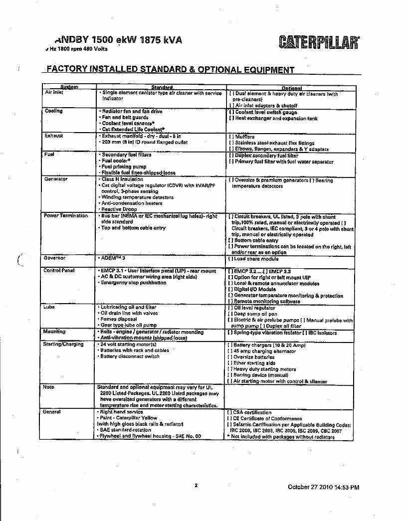
ANDBY 1500 ekW 11875 kVA j Hz 1800 rpm 480 Volts
FACTORY INSTALLED STANDARD & OPTIONAL EQUIPMENT
—System Standard Ootionnl Air Inlet • Single element canister type air cleaner with service
indicator [ 1 Dual element & heavy duty air cleaners (with
pre cleaners) 1 ] Air inlet adapters & shuloff
Cooling ' Radiator fan and fan drive ' Fan and belt guards • Coolant level sensors" • Cat Extended Ufa Coolant*
( I Coolant level switch gauge [ ) Heat exchanger and expansion tank
Exhaust • Exhaust manifold - dry - dual - 8 in • 203 mm IB in) ID round flanged outlet
[ I Mufflers (1 Stainless steel exhaust flex fittings [1 Elbows, flanges, expanders & Y adapters
Fuel • Secondary fuel filters ; • Fuel cooler* • Fuel priming pump • Flexible fuel lines-shipped' loose
I ) Duplex secondary fuel filter [ 1 Primary fuel filter with fuel water separator
Generator • Class H Insulation • Cat digital voltage regulator ICDVR) with kVAR/PF
control, 3-phase sensing • Winding temperature detectors ' Anti-condensation heaters • Reactive.Droop
[ ] Oversize & premium generators [ ) Bearing temperature detectors
Power Termination- • Bus bar (NEMA or IEC mechanical lug holes)- right side standard
. • Top and bottom cable entry
I / Circuit breakers, UL listed, 3 pole with shunt trip, 100% rated, manual or electrically operated [ ] Circuit breakers, IEC compliant, 3 or 4 pole with shunt trip, manual or electrically operated
{ r Bottom cable entry I ] Power terminations can be located on the right, left
and/or rear as an option Governor • ADEM™ 3 [ ] Load share module
Control Panel • EMCP 3.1 • User Interface panel (UIP) - rear mount »AC & DC customer wiring area (right side) • Emergency stop pushbutton
N EMCP 3,2... 1 ] EMCP 3.3 I ] Option for right or left mount UIP [ } Local & remote annunciator modules 1] DigitaH/O Module [jGenaratortemperaturemonitoring & protection [ ] Remote monitoring software
Lube " lubricating oil and filter • Oil drain line with valves • Fumes disposal • Gear type lube oil pump
( ) Oil level regulator 11 Deep sump oil pan [ I Electric & air prelube pumps [ ] Manual prelube with
sump pump ( ) Duplex oil filter Mounting • Rails - engine/generator/ radiator mounting
• Anti-vibration mounts (shipped loose) t ] Spring-type vibration isolator [ ] IBC Isolators
Starting/Charging • 24 volt starting motor(s) • Batteries with rack and cables • Battery disconnect switch
(1 Battery chargers (10 & 20 Amp) [ 145 amp charging alternator [ ] Oversize batteries 1) Ether starting aids I ] Heavy duty starting motors I I Barring device (manual) (J Air starting motor with control & silencer
Note Standard and optional equipment may vary for UL 2200 Listed-Packages. UL2200 Listed packages may have oversized generators with a different temperature rise and motorstarting characteristics.
General • Right hand service • Paint - Caterpillar Yellow (with high gloss black rails & radiator) • SAE standard rotation • Flywheel and flywheel housing - SAE No. 00
[ ] CSA certification [ ICE Certificate of Conformance 11 Seismic Certification per Applicable Building Codes: IBC 2000, IBC 2003, IBC 2006, IBC 2009, CBC 2007
* Not included with packages without radiators
2 October 27 2010 14:53 PM
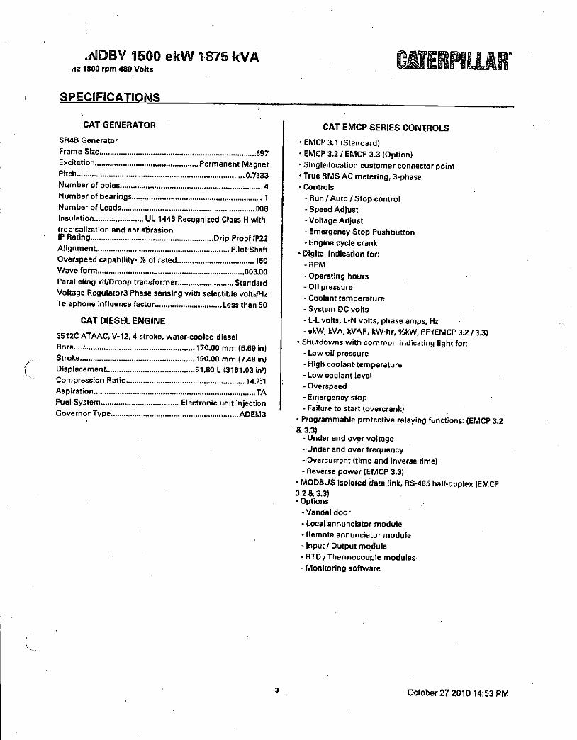
JSSDBY 1500 ekW 1875 kVA Az 1800 rpm 480 Volts
SPECIFICATIONS
r V
CAT GENERATOR
SR4B Generator
Frame Size ggy
Excitation Permanent Magnet Pitch.......... 0.7333 Number of poles 4
Number of bearings.......... 1
Number of Leads ; 006
Insulation UL 1446 Recognized Class H with
tropicalization and antiabrasion
IP Rating Drip Proof IP22
Alignment Pilot Shaft
Overspeed capability- % of rated..... 150
Wave form 003.00
Paralleling kit/Droop transformer Standard
Voltage Regulators Phase sensing with selectible volts/Hz
Telephone influence factor ; Less than 50
CAT DIESEL ENGINE
3512C ATAAC, V-12, 4 stroke, water-cooled diesel
Bore...... 170.00 mm (6.69 in)
Stroke 190.00 mm (7.48 in) Displacement 51.80 L (3161.03 in') Compression Ratio 14.7:1 Aspiration TA
Fuel System Electronic unit injection Governor Type ADEM3
CAT EMCP SERIES CONTROLS
• EMCP 3.1 (Standard)
• EMCP 3.2 / EMCP 3.3 (Option)
• Single location customer connector point • True RMS AC metering, 3-phase • Controls
- Run / Auto / Stop control
- Speed Adjust - Voltage Adjust
- Emergency Stop Pushbutton -Engine cycle crank
• Digital Indication for: -RPM
- Operating hours
- Oil pressure
- Coolant temperature - System DC volts
- L-L volts, L-N volts, phase amps, Hz
- ekW, kVA. kVAR, kW-hr, %kW, PF (EMCP 3.2/3.3) • Shutdowns with common indicating light for:
- Low oil pressure
- High coolant temperature - Low coolant level - Overspeed
- Emergency stop
- Failure to start (overcrank)
• Programmable protective relaying functions: (EMCP 3.2 &3.3)
- Under and over voltage
- Under and over frequency
- Overcurrent (time and inverse time)
- Reverse power (EMCP 3.3) • MODBUS isolated data link, RS-485 half-duplex (EMCP 3.2 & 3.3) • Options
-Vandal door
- Local annunciator module
- Remote annunciator module
- Input / Output module
- RTD / Thermocouple modules
- Monitoring software
(
3 October 27 201014:53 PM

STANDBY 1500 ekW 1875 kVA 60 Hz 1800 rpm 480 Volts
TECHNICAL DATA
Open Generator Set - -1800 rpm/60 Hz/480 Volts DM8260 EPA Certified for Stationary Emergency Application (EPA Tier, 2 emissions levels)
Generator Set Package Performance Genset Power rating @ 0.8 pf Gensat Power rating wi th fan
1875 kVA 1500 ekW
Coolant to aftercooler Coolant to aftercooler temp max 50 "C ' ,122 " F
Fuel Consumption 100% load with fan 7594 load wi th fan 50% load wi th fan
396.9 L/hr 310.9 L/hr 219.6 L/hr
104.6 Ga(/hr 82.1 Gal/hr 58.1 Gal/hr
Cooling System' Air f low restriction (system) Air f low (max @ rated speed for radiator arrangement) Engine Coolant capacity wi th radiator/exp. tank Engine coolant capacity Radiator coolant capacity
0.12 kPa 2075 m'/min 390.8 L 156.8 L 234.0 L
0.48 in. water 73278 cfm 103.2 gal 41.4 gal 61.8 gal
Inlet Air Combustion air inlet flow rate 129.5 m'/min 4573.3 cfm
Exhaust System Exhaust stack gas temperature Exhaust gas f low rate Exhaust flange size (internal diameter) Exhaust system backpressure (maximum allowable)
406.4 " C 313.2 mVmin 203.2 m m 6.7 kPa
763.5 " F 11060.6 cfm BifJi i)
26.9 in. water Heat Rejection
Heat rejection to coolant (total) Heat rejection to exhaust (total) Heat rejection to aftercooler Heat rejection to atmosphere f rom engine Heat rejection to atmosphere f rom generator
616 kW 1327 kW 482 kW 124 kW 64.1 kW
35032 Btu/min 75465 Btu/min 27411 Btu/min 7052 Btu/min 3845.4 Btu/min
Alternator 1
Motor starting capability @ 30% voltage dip Frame Temperature Rise
2670 skVA 697 130 ° C 234 -F
Lube System. Sump refill With filter 310.4 L 82.0 gal
Emissions (Nominal)' NOx g/hp-hr CO g/hp-hr HC g/hp-hr PM g/hp-hr
4.97 g/hp-hr .45 g/hp-hr .11 g/hp-hr .03 g/hp-hr
' For ambient and altitude capabilities consult your Cat dealer, Air flow restriction (system) is added to existing restriction from factory. '•'UL 2200 Listed packages may have oversized generators with a different temperature rise and motor starting characteristics. Generator temperature rise is based on a 40 degree C ambient.per NEMA MG1-32. ' Emissions data measurement procedures are consistent with those described In EPA CFR 40 Part 69, Subpart O & E and IS08178-1 for measuring HC, CO, PM, NOx. Data shown Is. based on steady state operating conditions of 77°F, 28,42 in HG and number 2 diesel fuel with 35° API and LHV of 18,390 btu/lb. The nominal emissions data shown is subject to instrumentation, measurement, facility and engine to engine variations. Emissions data is based on 100% load and thus cannot be used to compare to EPA regulations which use values based on a weighted cycle.
4 October 27 2010 14:53 PM

STANDBY 1500 ekW 1875 kVA 60 Hz 1800 rpm 480 Volts
RATING DEFINiTIONS AND CONDITIONS
Meets or Exceeds International Specifications: AS 1359,
CSA, IEC60034-1, ISO3046, IS08528, NEMA MG 1-22,
NEMA MG 1-33, UL508A, 72/23/EEC, 98/37/EC,
2004/108/EC
Standby - Output available with varying load for the
duration of the interruption of the normal source power.
Average power output is 70% of the standby power
rating. Typical operation is 200 hours per year, with
maximum expected usage of 500 hours per year.
Standby power in accordance with IS08528. Fuel stop
power in accordance with ISO3046. Standby ambients
shown indicate ambient temperature at 100% load which
results in a coolant top tank temperature just below the
shutdown temperature.
Ratings are based on SAE J1349 standard conditions.
These ratings also apply at ISO3046 standard conditions. Fuel rates are based on fuel oil of 35° API [16° C (60° F)]
gravity having an LHV of 42 780 kJ/kg (18,390 Btu/lb)
when used at 29° C (85° F) and weighing 838.9 g/liter
(7.001 lbs/U S. gal.). Additional ratings may be available
for specific customer requirements, contact your Cat
representative for details; For information regarding Low
Sulfur fuel and Biodiesel capability, please consult your Cat dealer.
S October 27 201014:53 PM

STANDBY 1500 ekW 1875 kVA
60 Hz 1800 rpm 480 Volts
DIMENSIONS
Package Dimensions Length 5895.0 mm 232.09 in Width 2537.5 mm 99,9 in Height 2749.5 mm 108.25 in Weight 14 035 kg 30,942 lb
NOTE: For reference only - do not use for installation design. Please contact your local dealer for exact weight and dimensions. (General Dimension Drawing #28460481.
Performance No.: DM8260
Feature Code: 512DE6C
Gen. Arr. Number: 2628100
Source: U.S. Sourced
October 27 2010 16297533
www.CAT-ElectricPower.com;
©2010 Caterpillar All rights reserved.
Materials and specifications are subject to change without notice, The International System of Units (SI) is used in this publication.
CAT, CATERPILLAR, SAFETY.CAT.COM their respective logos, 'Caterpillar Yellow,' and the POWER EDGE trade dress, as well as corporate and
product identity usedihereln, ere trademarks of Caterpillar and may not be used without permission.
6

Page 1 of 1
Engine Selection I De-rate Calculator / Speed Interpolator USA Purchased, USA Installed; 2011 Models. UL/FM Approved, Heat Exchanger Cooled
DATE: 2/18/2011
PUMP Pump Max Power: 315 BHP REQUIREMENTS: RPM(s): 1800
DERATE Altitude: 185 (feet) PARAMETERS: Ambient Temperature: 77 (°F)
Right Angle Gear Loss: 0% Derate Percent: .0
APPLICATION Customer: INFO: Job Name:
J o b Number : Run By:
RESULTS:
Model RPM Rated HP (KW) Derate HP (KW) Emissions Tier Interpolation Data (RPM, HP)
JU6H-UFAD98 1800 315(235) T3-Certified Not used
NOTE: Derated HP takes into account alt the input derates for attitude, temperature and Right Angle Gearbox. When no.derates are inpui, this column will be blank and enginei selection's) will be based upon Rated HP When trie Derated HP column is fitted m. then the engine selection^) are based upon Ibis value
DEFINITIONS: OUUFM. Engine lhal is Underwriters Laboratories Listed and Factory Mutual Approved
»LPCB - Engine that Is Loss Prevention Council Board Approved
•NL - Non-Lrsled Engine has no private agency certification, like UL. or Insurance company certification, like FM It applies to any engine that is not UL Listed:or FM Approved, end is buiil lo meet individual European country specifications ' '
North American Offices, 3133 East Kemper Road * Cincinnati. Ohio * 45241 * USA' Tel: +1 (513) 475-3473 * Fax. +115i3| 771-0726 European Office Grange Wonxs • Lomond Road' Coatbridge. Scotland " MLS 2NN * Tel:+*4 (0)1236 423 946 ' Fax: •44 (0)1236 427 274
http://wAvw.clarkefire.com/Calculators/PrintEngineSeI.htm 2/18/2011

Page 1 of 1
Fire Protection Products, Inc. Exhaust Backpressure Calculator • Results
Calculations made 2/18/2011
Data input by:
Input Data [Customer: Job Name: Job Number. Engine Data: Piping Data: Silencer Data: Manufacturer: Clarke Pipe Size: 5" Manufacturer: Clarke USA Model: JU6H-UFAD98 #90' elbow orY: Pipe Size (in): 5 RPM: 1760 Number 45° elbows: Model: C06545 HP:315 Number Tees: Application: Industrial HP:315
Straight Pipe (Feet): 30 Connection: 150# Flange
Output Data: Exh Flow (CFM): 1400 Temperature (° F): 961 Max Backpressure (inches water): 30 Mln Backpressure (inches water): 0 Std. Exhaust Dia (In): 5
END IN ~ f '
(r-\ "V-! -erajour
"63 125 250 500 1000 2000 4000 8000 OCTAVE BAND CENTER FREQUENCY (Hz)
Exhaus t Pipe Recommendation: BACKPRESSURE CALCULATIONS [Inches water)
6.5 Pipe BACKPRESSURE CALCULATIONS [Inches water) + 8.0 Silencer (see note 1)
BACKPRESSURE CALCULATIONS [Inches water)
BACKPRESSURE CALCULATIONS [Inches water)
14,5 Total
BACKPRESSURE CALCULATIONS [Inches water)
30.0 Maximum Allowable Backpressure
BACKPRESSURE CALCULATIONS [Inches water)
Result: Total Backpressure is lower than minimum
U CAUTION Silencer Backoiessure is based upon a Clarke USA provided Silencer Actual Silencer Backpressure will vary depending upon the actual Silencer used (manufocturer. size, type end model) |i 'r»e tou>( Bockprflssure from the pipe. Silencer and wifice plate M required) is dose to the engine Maximum Allowed Bockpressuie. n is nighty recommended jouobiein the ecwai Babkoressure {for the engine eKhousiTiciv given above) on the Silencer bo>ng used and then oonArm that the tola) Backpressure is srio under the Meximum Ukwad Backpressure t) Schedule 40 pipe used in calculations 3) Alt oipes^es and lengths era in inches and feel 1) WARNING' The total Backcressuie;ts less than the engine permissible Backpressure in order,to gel me maximum Backpressure above die engine permissible kmit you must *ienge one or mors of the following: pipe size: pipe length: Silencer eiio. Silencer type.
forth American OBces
»33 East Kemper Road • Cincinnati. Ohio ' 45241' USA • Tel '1 (613) 771:2200 • Fax +1 (513) 771-0726
European Office. Sranne Works' Lomond Road • Coaibndoe. Scotland • MLS 2NN • Tel. • « (011236 429 946 * Fax- «44 (0)1236 427 274
http://www.clarkefirexom/Calculators/PrintExhaust.htm 2/18/2011