Embed Size (px)
Citation preview
8/14/2019 2 Shear Stress and Strain
http://slidepdf.com/reader/full/2-shear-stress-and-strain 1/16
DMV 4343JAN ~ JUN `07
DEPARTMENT MANUFACTURING / PRODUCT DESIGN /MOULD / TOOL AND DIE
SEMESTER 4 / 6
COURSE MECHANICS OF MATERIALS DURATION 8 hrsCOURSE CODE DMV 4343 / DMV 5343 REF. NO.
VTO’S NAME MISS AFZAN BINTI ROZALIMR RIDHWAN BIN RAMELI
PAGE 13
TOPICSHEAR STRESS AND STRAIN
SUB TOPIC2.1 Simple Shear Stress2.2 Shear Deformation2.3 Simple Shear Strain
Chapter 2 SHEAR STRESS AND STRAIN p1
INFORMATION SHEET
8/14/2019 2 Shear Stress and Strain
http://slidepdf.com/reader/full/2-shear-stress-and-strain 2/16
DMV 4343JAN ~ JUN `07
Chapter 2 SHEAR STRESS AND STRAIN p2
REF NO. :
PAGE :
8/14/2019 2 Shear Stress and Strain
http://slidepdf.com/reader/full/2-shear-stress-and-strain 3/16
DMV 4343JAN ~ JUN `07
2.1 Simple Shear Stress
In the preceding sections of Chapter 1, you were introduced to stress and strain through a
discussion of normal stress and extensional strain. We turn now to a discussion of shear
stress and shear strain, which are used, respectively, to quantify the distribution of force
acting tangent to a surface and the angle change produced by tangential forces.
Definition of Shear Stress.
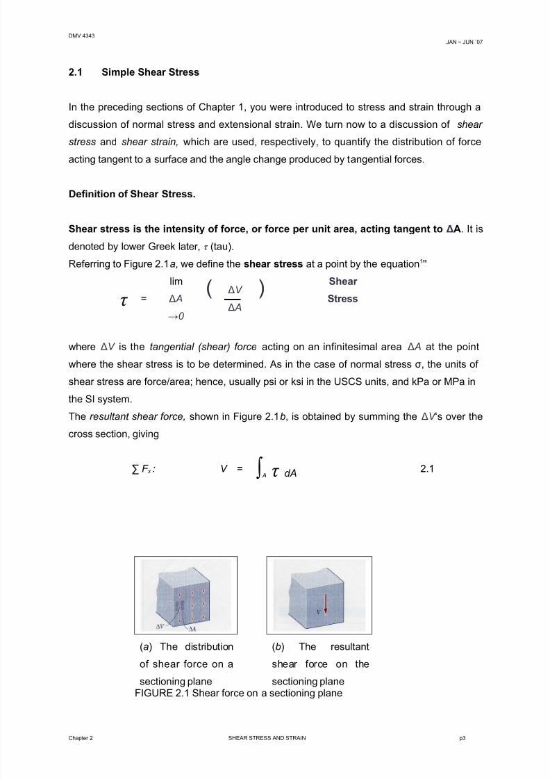
Shear stress is the intensity of force, or force per unit area, acting tangent to ΔA. It is
denoted by lower Greek later, τ (tau).
Referring to Figure 2.1a, we define the shear stress at a point by the equation1''
τ =
lim
Δ A
→0
( ΔV
Δ A
) Shear
Stress
where ΔV is the tangential (shear) force acting on an infinitesimal area Δ A at the point
where the shear stress is to be determined. As in the case of normal stress σ, the units of
shear stress are force/area; hence, usually psi or ksi in the USCS units, and kPa or MPa in
the SI system.
The resultant shear force, shown in Figure 2.1b, is obtained by summing the ΔV ‘s over the
cross section, giving
(a) The distribution
of shear force on a
sectioning plane
(b) The resultant
shear force on the
sectioning planeFIGURE 2.1 Shear force on a sectioning plane
Chapter 2 SHEAR STRESS AND STRAIN p3
∑ F x : V = ∫ A τ dA 2.1
8/14/2019 2 Shear Stress and Strain
http://slidepdf.com/reader/full/2-shear-stress-and-strain 4/16
DMV 4343JAN ~ JUN `07
Chapter 2 SHEAR STRESS AND STRAIN p4
8/14/2019 2 Shear Stress and Strain
http://slidepdf.com/reader/full/2-shear-stress-and-strain 5/16
DMV 4343JAN ~ JUN `07
Average Shear Stress.
Even when the exact shear stress distribution on a surface cannot be readily determined, it
is sometimes useful to calculate the average shear stress on the surface. This is given by
τ avg =
V
As
Average Shear
Stress 2.2
where V is the total shear force acting on area As. In order to determine τ avg we must first
determine what area has shear stress acting on it, and then, using a free-body diagram,
determine the value of the shear force, V, acting on this area.
Direct Shear.
The average shear stress can be readily calculated in the case of direct shear, examples of
which are shear in bolts, pins, and rivets, and shear in welds and lap splices.
Direct shear (or simple shear) is caused by forces that act parallel to a particular surface of some part,
with the direct result of shearing, or lending to shear (i.e., sever), the material at that surface.
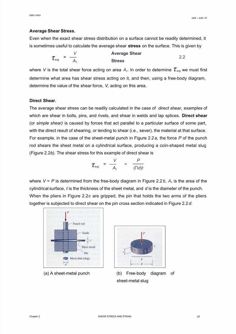
For example, in the case of the sheet-metal punch in Figure 2.2a, the force P of the punch
rod shears the sheet metal on a cylindrical surface, producing a coin-shaped metal slug
(Figure 2.2b). The shear stress for this example of direct shear is
τ avg =
V
As
=P
(Πd )t
where V = P is determined from the free-body diagram in Figure 2.2b, As is the area of the
cylindrical surface, t is the thickness of the sheet metal, and d is the diameter of the punch.
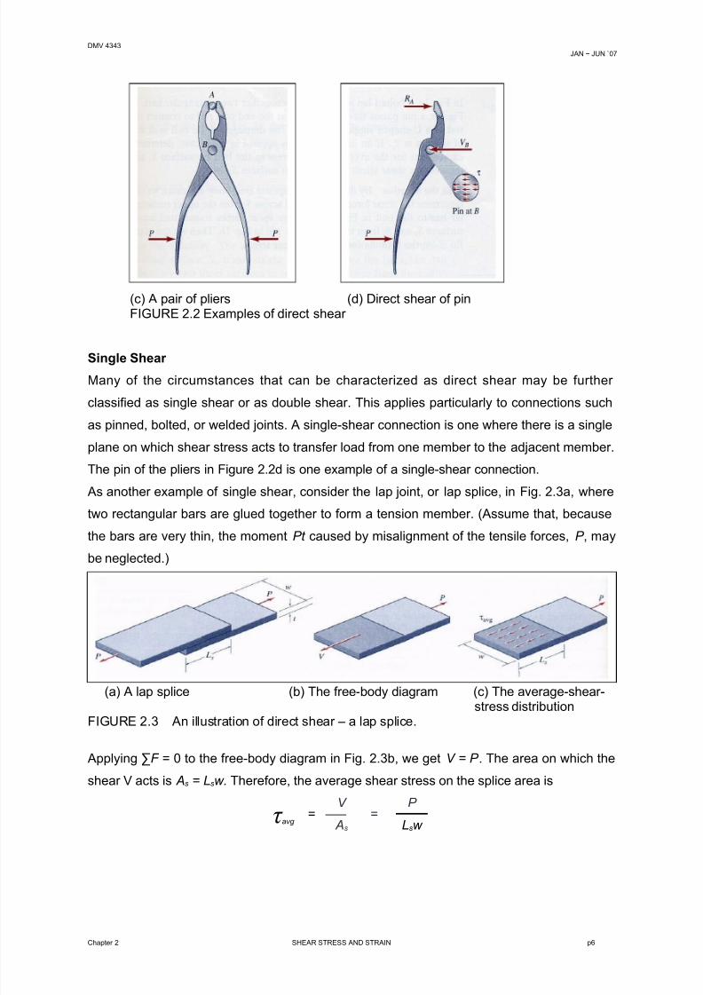
When the pliers in Figure 2.2c are gripped, the pin that holds the two arms of the pliers
together is subjected to direct shear on the pin cross section indicated in Figure 2.2d .
(a) A sheet-metal punch (b) Free-body diagram of
sheet-metal slug
Chapter 2 SHEAR STRESS AND STRAIN p5
8/14/2019 2 Shear Stress and Strain
http://slidepdf.com/reader/full/2-shear-stress-and-strain 6/16
DMV 4343JAN ~ JUN `07
(c) A pair of pliers (d) Direct shear of pinFIGURE 2.2 Examples of direct shear
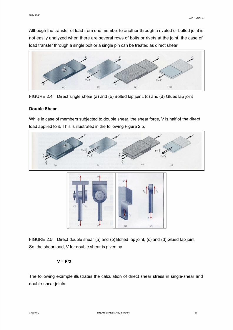
Single Shear
Many of the circumstances that can be characterized as direct shear may be further
classified as single shear or as double shear. This applies particularly to connections such
as pinned, bolted, or welded joints. A single-shear connection is one where there is a single
plane on which shear stress acts to transfer load from one member to the adjacent member.
The pin of the pliers in Figure 2.2d is one example of a single-shear connection.
As another example of single shear, consider the lap joint, or lap splice, in Fig. 2.3a, where
two rectangular bars are glued together to form a tension member. (Assume that, because
the bars are very thin, the moment Pt caused by misalignment of the tensile forces, P , may
be neglected.)
(a) A lap splice (b) The free-body diagram (c) The average-shear-stress distributionFIGURE 2.3 An illustration of direct shear – a lap splice.
Applying ∑F = 0 to the free-body diagram in Fig. 2.3b, we get V = P . The area on which the
shear V acts is As = Lsw. Therefore, the average shear stress on the splice area is
τ avg =
V
As
=P
Lsw
Chapter 2 SHEAR STRESS AND STRAIN p6
8/14/2019 2 Shear Stress and Strain
http://slidepdf.com/reader/full/2-shear-stress-and-strain 7/16
DMV 4343JAN ~ JUN `07
Although the transfer of load from one member to another through a riveted or bolted joint is
not easily analyzed when there are several rows of bolts or rivets at the joint, the case of
load transfer through a single bolt or a single pin can be treated as direct shear.
FIGURE 2.4 Direct single shear (a) and (b) Bolted lap joint, (c) and (d) Glued lap joint
Double Shear
While in case of members subjected to double shear, the shear force, V is half of the direct
load applied to it. This is illustrated in the following Figure 2.5.
FIGURE 2.5 Direct double shear (a) and (b) Bolted lap joint, (c) and (d) Glued lap joint
So, the shear load, V for double shear is given by
V = F/2
The following example illustrates the calculation of direct shear stress in single-shear and
double-shear joints.
Chapter 2 SHEAR STRESS AND STRAIN p7
8/14/2019 2 Shear Stress and Strain
http://slidepdf.com/reader/full/2-shear-stress-and-strain 8/16
DMV 4343JAN ~ JUN `07
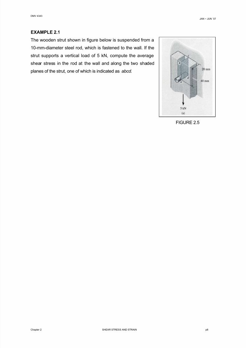
EXAMPLE 2.1
The wooden strut shown in figure below is suspended from a
10-mm-diameter steel rod, which is fastened to the wall. If the
strut supports a vertical load of 5 kN, compute the average
shear stress in the rod at the wall and along the two shaded
planes of the strut, one of which is indicated as abcd.
FIGURE 2.5
Chapter 2 SHEAR STRESS AND STRAIN p8
8/14/2019 2 Shear Stress and Strain
http://slidepdf.com/reader/full/2-shear-stress-and-strain 9/16
DMV 4343JAN ~ JUN `07
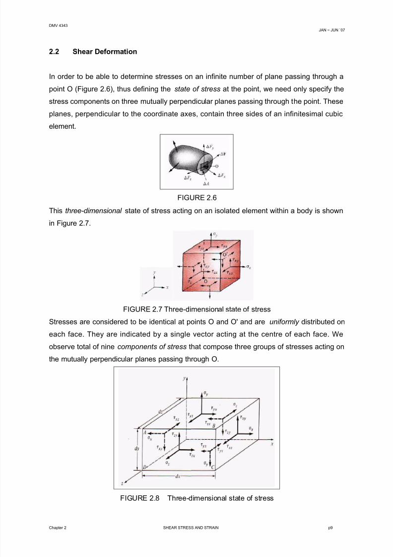
2.2 Shear Deformation
In order to be able to determine stresses on an infinite number of plane passing through a
point O (Figure 2.6), thus defining the state of stress at the point, we need only specify the
stress components on three mutually perpendicular planes passing through the point. These
planes, perpendicular to the coordinate axes, contain three sides of an infinitesimal cubic
element.
FIGURE 2.6
This three-dimensional state of stress acting on an isolated element within a body is shown
in Figure 2.7.
FIGURE 2.7 Three-dimensional state of stress
Stresses are considered to be identical at points O and O' and are uniformly distributed on
each face. They are indicated by a single vector acting at the centre of each face. We
observe total of nine components of stress that compose three groups of stresses acting on
the mutually perpendicular planes passing through O.
FIGURE 2.8 Three-dimensional state of stress
Chapter 2 SHEAR STRESS AND STRAIN p9
8/14/2019 2 Shear Stress and Strain
http://slidepdf.com/reader/full/2-shear-stress-and-strain 10/16
DMV 4343JAN ~ JUN `07
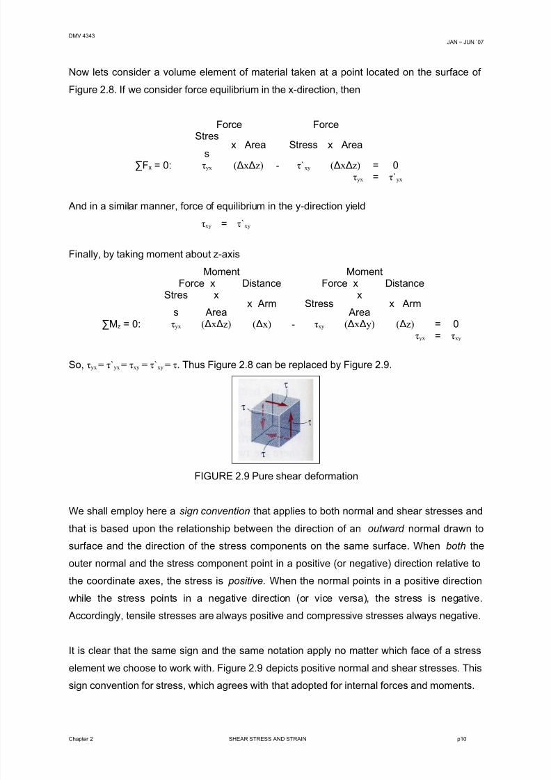
Now lets consider a volume element of material taken at a point located on the surface of
Figure 2.8. If we consider force equilibrium in the x-direction, then
Force Force
Stress
x Area Stress x Area
∑Fx = 0: τyx (ΔxΔz) - τ`xy (ΔxΔz) = 0τyx = τ`yx
And in a similar manner, force of equilibrium in the y-direction yield
τxy = τ`xy
Finally, by taking moment about z-axis
Moment MomentForce x Distance Force x DistanceStres
s
x
Areax Arm Stress
x
Areax Arm
∑Mz = 0: τyx (ΔxΔz) (Δx) - τxy (ΔxΔy) (Δz) = 0τyx = τxy
So, τyx = τ`yx = τxy = τ`xy = τ. Thus Figure 2.8 can be replaced by Figure 2.9.
FIGURE 2.9 Pure shear deformation
We shall employ here a sign convention that applies to both normal and shear stresses and
that is based upon the relationship between the direction of an outward normal drawn to
surface and the direction of the stress components on the same surface. When both theouter normal and the stress component point in a positive (or negative) direction relative to
the coordinate axes, the stress is positive. When the normal points in a positive direction
while the stress points in a negative direction (or vice versa), the stress is negative.
Accordingly, tensile stresses are always positive and compressive stresses always negative.
It is clear that the same sign and the same notation apply no matter which face of a stress
element we choose to work with. Figure 2.9 depicts positive normal and shear stresses. This
sign convention for stress, which agrees with that adopted for internal forces and moments.
Chapter 2 SHEAR STRESS AND STRAIN p10
8/14/2019 2 Shear Stress and Strain
http://slidepdf.com/reader/full/2-shear-stress-and-strain 11/16
DMV 4343JAN ~ JUN `07
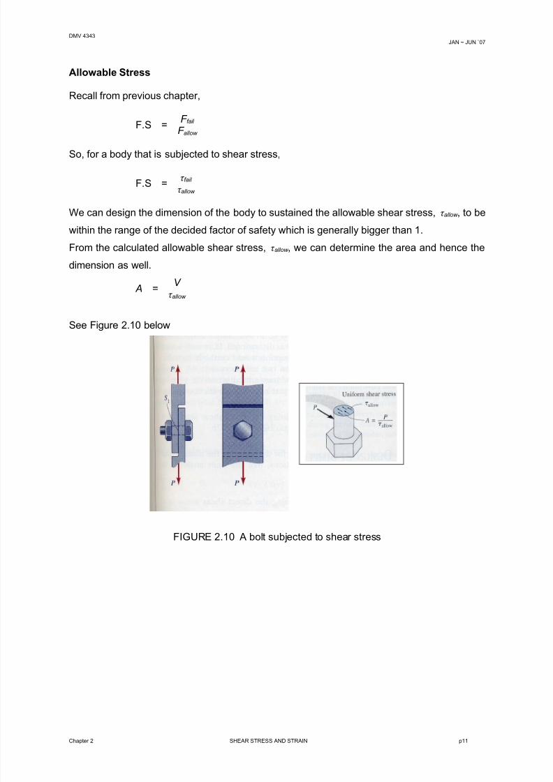
Allowable Stress
Recall from previous chapter,
F.S =F fail
F allow
So, for a body that is subjected to shear stress,
F.S =τ fail
τ allow
We can design the dimension of the body to sustained the allowable shear stress, τ allow , to be
within the range of the decided factor of safety which is generally bigger than 1.
From the calculated allowable shear stress, τ allow , we can determine the area and hence the
dimension as well.
A =V
τ allow
See Figure 2.10 below
FIGURE 2.10 A bolt subjected to shear stress
Chapter 2 SHEAR STRESS AND STRAIN p11
8/14/2019 2 Shear Stress and Strain
http://slidepdf.com/reader/full/2-shear-stress-and-strain 12/16
DMV 4343JAN ~ JUN `07
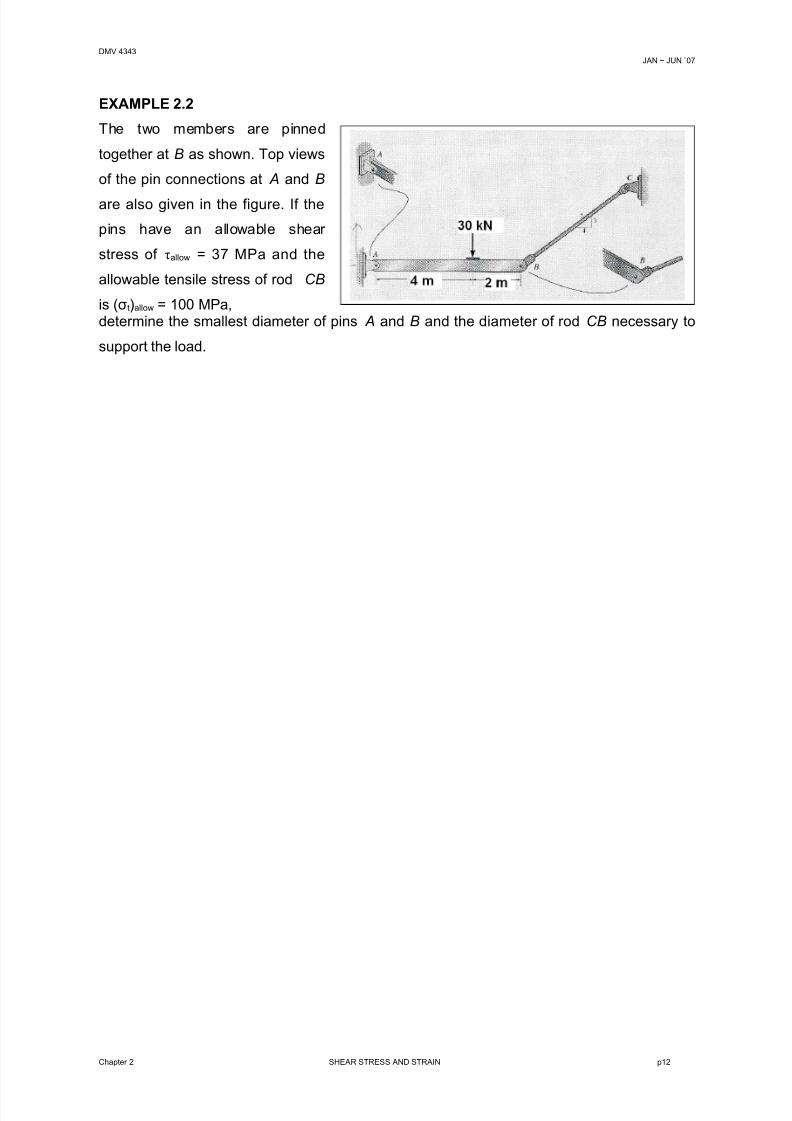
EXAMPLE 2.2
Chapter 2 SHEAR STRESS AND STRAIN p12
The two members are pinned
together at B as shown. Top views
of the pin connections at A and B
are also given in the figure. If the
pins have an allowable shear
stress of τallow = 37 MPa and the
allowable tensile stress of rod CB
is (σt)allow = 100 MPa,determine the smallest diameter of pins A and B and the diameter of rod CB necessary to
support the load.
8/14/2019 2 Shear Stress and Strain
http://slidepdf.com/reader/full/2-shear-stress-and-strain 13/16
DMV 4343JAN ~ JUN `07
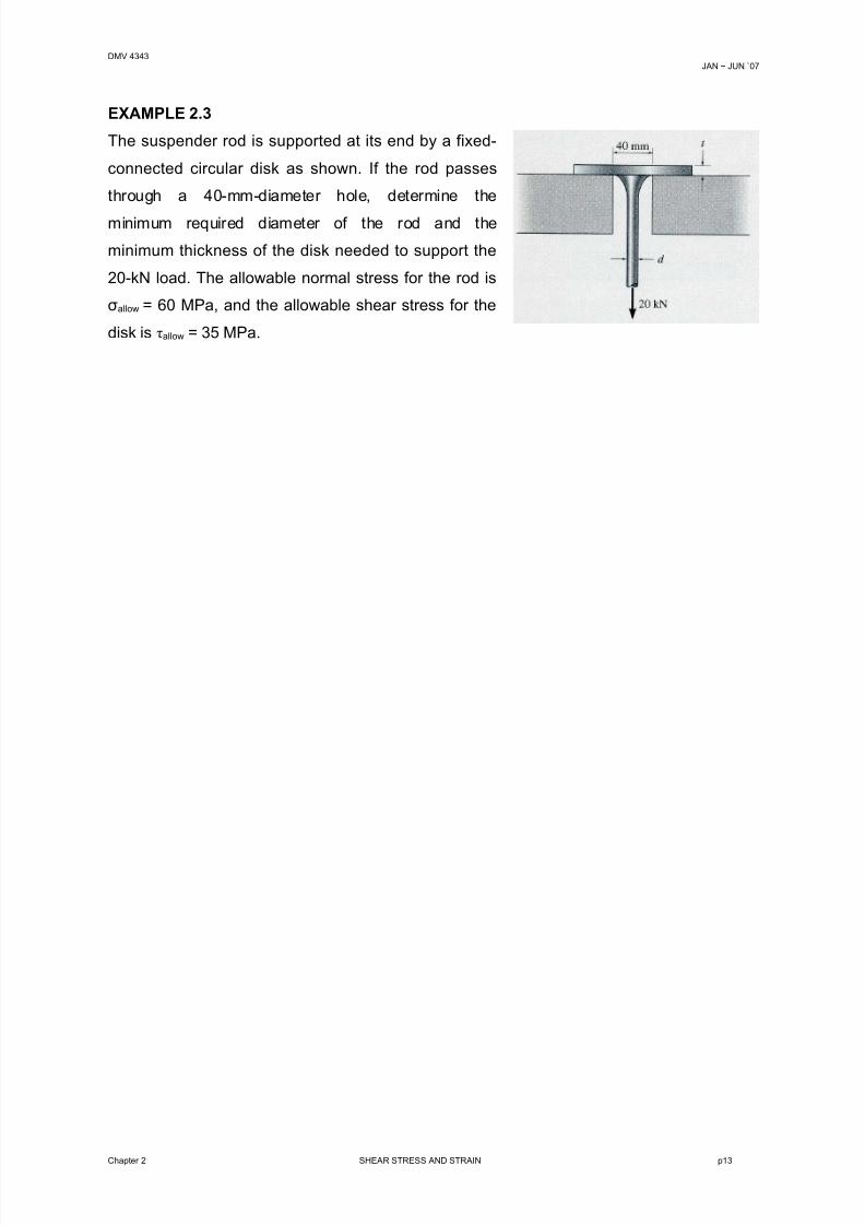
EXAMPLE 2.3
Chapter 2 SHEAR STRESS AND STRAIN p13
The suspender rod is supported at its end by a fixed-
connected circular disk as shown. If the rod passes
through a 40-mm-diameter hole, determine the
minimum required diameter of the rod and the
minimum thickness of the disk needed to support the
20-kN load. The allowable normal stress for the rod is
σallow = 60 MPa, and the allowable shear stress for the
disk is τallow = 35 MPa.
8/14/2019 2 Shear Stress and Strain
http://slidepdf.com/reader/full/2-shear-stress-and-strain 14/16
DMV 4343JAN ~ JUN `07
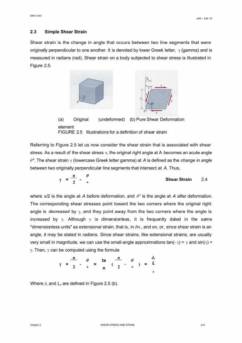
2.3 Simple Shear Strain
Shear strain is the change in angle that occurs between two line segments that were
originally perpendicular to one another. It is denoted by lower Greek letter, γ (gamma) and is
measured in radians (rad). Shear strain on a body subjected to shear stress is illustrated inFigure 2.5.
(a) Original (undeformed)element
(b) Pure Shear Deformation
FIGURE 2.5 Illustrations for a definition of shear strain
Referring to Figure 2.5 let us now consider the shear strain that is associated with shear
stress. As a result of the shear stress τ, the original right angle at A becomes an acute angle
θ * . The shear strain γ (lowercase Greek letter gamma) at A is defined as the change in angle
between two originally perpendicular line segments that intersect at A. Thus,
γ =
π
-
θ
* Shear Strain 2.42
where π / 2 is the angle at A before deformation, and θ * is the angle at A after deformation.
The corresponding shear stresses point toward the two corners where the original right
angle is decreased by γ, and they point away from the two corners where the angle is
increased by γ. Although γ is dimensionless, it is frequently dated in the same
"dimensionless units" as extensional strain, that is, in./in., and on, or, since shear strain is an
angle, it may be stated in radians. Since shear strains, like extensional strains, are usually
very small in magnitude, we can use the small-angle approximations tan(-γ) = γ and sin(γ) =
γ. Then, γ can be computed using the formula
γ =
π
-θ
* ≈
ta
n(
π
-θ
* ) =
δs
2 2L
s
Where δ s and Ls are defined in Figure 2.5 (b).
Chapter 2 SHEAR STRESS AND STRAIN p14
8/14/2019 2 Shear Stress and Strain
http://slidepdf.com/reader/full/2-shear-stress-and-strain 15/16
DMV 4343JAN ~ JUN `07
Material Properties in Shear.
Material properties relating to shear, like those for normal-stress-extensional-strain
behaviour, must be determined experimentally. The material properties in shear, such as
yield stress in shear, shear modulus of elasticity, and so on, may be obtained from a torsion
test, which will be discussed later in Section 4.4. For example, linearly elastic behavior in
shear is described by Hooke's Law for shear, which
τ = G γ Hooke’s Law for Shear 2.5
The constant of proportionality, G, is called the shear modulus of elasticity, or, simply, the
shear modulus. Like E, the shear modulus G is usually expressed in units of ksi or GPa. The
shear properties are closely related to the extensional properties through equations of
equilibrium and geometry of deformation.
Chapter 2 SHEAR STRESS AND STRAIN p15
8/14/2019 2 Shear Stress and Strain
http://slidepdf.com/reader/full/2-shear-stress-and-strain 16/16
DMV 4343JAN ~ JUN `07
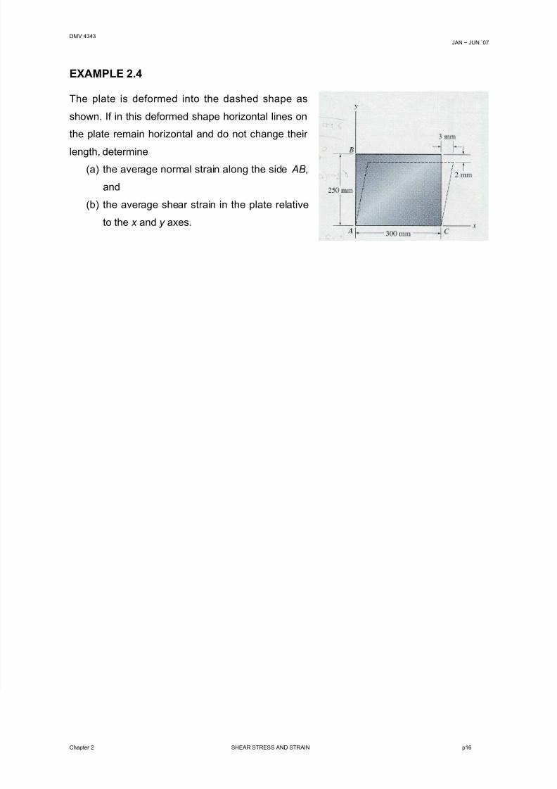
EXAMPLE 2.4
The plate is deformed into the dashed shape as
shown. If in this deformed shape horizontal lines on
the plate remain horizontal and do not change their length, determine
(a) the average normal strain along the side AB,
and
(b) the average shear strain in the plate relative
to the x and y axes.
Chapter 2 SHEAR STRESS AND STRAIN p16


![01 Welcome [ ] · PDF fileFigure 3. Shear stress strain relationship for the panels tested: a) Panel built with mortar M10 / UNI-EN 998-2 1 Figure 3. Shear stress strain relationship](https://img.pdfslide.net/doc/110x75/5aa8197a7f8b9aac258b6672/01-welcome-3-shear-stress-strain-relationship-for-the-panels-tested-a-panel.jpg)