Embed Size (px)
Citation preview

PERPUSTAKAAN UMP
UI 1111111111111111111111111111111111111111111 I 0000065636
Estimation of corrugated cardboard strength with a new tensile or shear test method
Master Thesis of Mechanical Engineering in the Graduate School of Engineering,
Nagaoka University of Technology, Niigata, Japan
No.07306986 Norfarizabinti Ab .Wahab
PERPUSTAKAAN UNWERS!TI MALAYSIA PAHANG
UV an-;'
No.PanggIlan
I3 Tarikh
29

February 13th, 2012
Estimation of corrugated cardboard strength with a new tensile or shear test method
No.07306986
Norfariza binti Ab.Wahab
Master Thesis of Mechanical Engineering in the Graduate School of Engineering,
Nagaoka University of Technology,
Niigata, Japan
The corrugated cardboard is widely used in manufacturing industries as a packaging
and transportation material. Faculty of corrugated cardboard is depended on the
fragility, weight, thickness, toughness and so on. The strength of corrugated cardboard
changed with the fabrication process, used atmosphere and variety of loading patterns.
On the machining process of corrugated cardboard box, the cutting and ruling
technology is very important factor. The effects of these factors on the strength of
corrugated cardboard have not yet enough been identified.
In general, the corrugated cardboard was composed with three layer of paperboard.
One is outside liner and inside liner and the other is corrugated medium. The top of
corrugated medium is bonded with glue on outside or inside layer surface. The bonded
space was decided by company standard. The evolutional method of bonding strength
had not been established. The development of new simple method has been needed.
In this research, to establish the evaluation method of strength of corrugated
cardboard material, new practical tensile test and shear test, considering the glue
bonding strength, was proposed and the factory of these test method was investigated.
In current studies, it was too hard to evaluate the reproductive tensile and shear
strength of corrugated cardboard, because of fabrication method of the cut specimen
and the deformation of chuck position. On the shear test, as the direction of parallel
chuck changed during loading process, the specimen was rotated. In this research, the
new developed method of tensile and shear was accomplished, the reproduced strength
could be obtained. The fatigue test was tried on the shear test to investigate the effect
of thickness of specimen.
The main results of this research were summarized as follow.
1. A new method of tensile and shear test on corrugated cardboard was developed.

2. The good reproduce strength value obtained using the new method.
3. The effect of corrugated medium on the tensile strength was investigated
comparing the strength of inside and outside liner and the tensile strength of this
method.
4. On the shear test, the. boring étrength of glue area was assumed with changing
the number of bonding top. Over 5 bonding top condition, the fracture occurred at
the outside and inside liner.
5. On the fatigue test of shear method, even under the 10% of fracture strength, the
fracture generated at 33 times.

Estimation of corrugated cardboard strength with a new tensile or shear test method
Chapter 1 Introduction
Chapter 1 Introduction
1.1 Introduction of research Corrugated cardboard can be defined as "the structure formed by gluing one or more
layers of fluted corrugating medium to one or more flat facings of linerboard" [1] (see Fig.
1). It has been used as packing material for more than 100 years, but it still maintains a
healthy share of the total market despite increasing competition from plastics. One
reason for continued demand for corrugated cardboard packaging is its unique
combination of attributes:
• It has a high stiffness to weight ratio. Compared to other rigid packaging materials,
corrugated cardboard delivers relatively high stiffness at a relatively low price.
This was demonstrated by Steenberg et al. [2] in 1970, and the comparisons are still
broadly valid (Fig. 2)
• It has reasonable shock resistance and cushioning properties and the air space in
the corrugated structure imparts good thermal insulation.
• It is made from a natural and renewable resource and is fully biodegradable and
recyclable. In some European countries over 70% of all corrugated packaging is
collected and recycled [3].
• It is versatile and can be used for the diverse packaging requirements of different
industries. It can carry a high quality printed image for point of sale marketing and
can be used on high speed automated packing lines.
FLUTEO CanRUATING
MEDnJM
FACINC
Fig. 1 Section through corrugated cardboard showing the fluted structure

Other 9.9M Tewsprint 36M Graphic 9M ao/ 12% 40
145.1M 49%
Estimation of corrugated cardboard strength with a new tensile or shear test method
Chapter 1 Introduction
ALUWNIUM
STCEiL PLATE
UI
GLASS LU
LIA
SOLID BOARDCORRUGATCU BOARD
RELATIVE STIFFNESS
Fig.2 Comparison of relative stiffness and price of various rigid packaging materials.
(After Ref. [21)
In 1997, total world paper and board production for all grades was 299 million tones [3].
Of the 145.1 million tone of packaging grades, almost 80 million tones was corrugating
materials, which is second only to graphic papers in terms of volume (Fig. 3). Total
world shipments of corrugated cardboard in 1999 were 124.9 billion m 2 [4], or almost
125, 00 km2. By 2001, sufficient corrugated cardboard will be produced annually in the
world to totally cover a country the size of England in a continuous layer. Production
increased by an average of 3.6% in the years 1995-1999 [41, and the industry is forecast
to grow at a rate of about 1% faster than world GDP, or 3.1% per annum, up to 2012 [5].
Fig. 3 World paper and board production in millions of tones by grade. (Data from ref.
[3].)
2

Estimation of corrugated cardboard strength with a new tensile or shear test method
Chapter 1 Introduction
1.1.1 The Manufacturing Process
The modern corrugator bears a strong likeness to the original Langston designs [61,
with two independently controlled stations to apply the facing (see Fig. 4).
- runs!, !tts! 1!IDIS
Pin c9rr ii!lud tillhfli rn us am konq
- Shr€1l&er - 1
Fig. 4 Modern corrugator for manufacturing corrugated cardboard (Ref. [161).
The first facing, called the single face (SF) liner, is glued to the medium at the same
station that forms the characteristics flutes (Fig. 5). The corrugating medium at is fed
from an unwind stand around a preheater roll, then into the labyrinth between two
corrugated rolls (locations 2 and 3 in Fig. 5).
dIivy
UPPER CORRUGATOR ROLL
MEDIUM
LOWER CORRUGATOR ROLL
CLOSE-UP OF LABYRINTH
TO DOUBLE BACKER
UPPER ORRUGATO
ROLL
LO GAT R ROLL
Location DescriptionResidence Time, ins
Preconditioning before the cotrugator roll nip - 2 Labyrinth entering the coriugator roll nip 6.0 3 Labyrinth leaving the corrugator roll nip 1 .5 4 Pressure compartment before the glue mdli 94.5 5 Glue application 3.0 6 Pressure compartment before the pressurO roll 60.0 7 Pressing the liner against the glued flute tips . 1.1 5 S Formation of the bond after the pressure roll
Fig. 5 Schematic of the single facer station on a modern corrugator. The table shows
approximate residence times at the various stages of the process. (Main diagram
adapted from Ref. 62. Inset courtesy of Ian Chalmers, Papro, New Zealand.)
3

Estimation of corrugated cardboard strength with a new tensile or shear test method
Chapter 1 introduction
These rolls are steam heated, and the nip pressure is controllable. The medium passes
between the rolls, is compressed and thermally softened, and molds to the contours of
the corrugated rolls. This process relies on a combination of paper properties such as hot
coefficient of friction and ability to stretch and process variable such as web tension, as
comprehensively reviewed in the work of Gottsching and Otto [614111 and Whitsitt [121.
The medium is held in place on the corrugator roll by either vacuum or pressure
(locations 4 and 6 in Fig. 5) or, on older machines, by the use of mechanical fingers. An
adhesive is metered onto the tips of the medium corrugations by an applicator roll
(location 5), and the liner is bought into contact with the medium at the pressure roll
(location 7). The resulting structure is called single faced board, because it has only one
liner glued to the medium. The bond between the two still wet (or "green" as it is known)
at this stage but has sufficienttack to hold the structure together. The factors affecting
the development of green bond strength are explored in the articles by Batelka [13, 141.
The board is transported to the next station via the bridge, which is a temporary
holding facility. This is necessary because the two stations on the corrugator operate
independently, and the process would be difficult to control without the provision of a
buffer of single face material.
The second layer of liner is added at the double facer, also known as the double backer
station. Adhesive is applied to the exposed tips of the corrugating medium, and the
second liner is bought into contact under light pressure. The corrugated board then
passes over hot plates to cure the adhesive. The final stage is machine direction (MD)
slitting and scoring at the triplex station, followed by cross direction (CD) cutting by a
rotary cut off knife. These operations produce a blank of the size required for the box
making operation. More details of the corrugating operation can be obtained in the book
The Corrugator [15]. The corrugated cardboard then passes through several other
conversion processes, depending on the nature and complexity of the use (Fig. 6).
FLEXO EOLcEF WiEJ
II?'FTiNQ - CEA.S1 N 3 (D)
sLQrrIHc L IECLJrT P.1 G
TKI N srRA.PPi N:c
IDLE crrE.
IEP.SIN (C1) aIEcLrrIP.Jc SiCK PIG
P1NTE. I sL_arrEl
O1SIt4G (D)
Fig. 6 Conversion operations on corrugated cardboard.
4

MEDIUM OR FLUTING
••- ,MD
MANUFACTURING OR MACHINE DIRECTION
Estimation of corrugated cardboard strength with a new tensile or shear test method
Chapter 1 Introduction
1.1.2 The Structure of Corrugated Cardboard
Corrugated cardboard is a unique construction with a series of connected arches
separating the two facings. This provides the structure with rigidity while maintaining
an excellent strength to weight ratio. The structure has different properties in its three
principal directions (FigJ)., The balance of properties in the three principal axes will depend on several
characteristics of the materials and structure, including
1. The directional strength of the facings. The paper used for the facings or liners in
corrugated cardboard is generically known as linerboard. It is commonly a two
layered structure with the greater strength in the direction of manufacture, or
machine direction. This is-due to the nature of the paper making process, which
tends to align fibers in the machine direction.
2. The ability of the medium to keep the facings apart. This will depend on the
compressive and shear strength of the flute structure, which also be affected by the
strength and integrity of the glue lines between the medium and the liners.
3 The weight per unit area of the facings and medium Components with higher
weight per unit area (grammage) will produce a structure with higher strength.
The balance between the grammage of the liners and the medium will also affect
structural strength. 4. The geometry of the flutes-the height and number of flutes per unit length (pitch).
Corrugated cardboard can consist of combinations of layer with different liners and
flute geometry, such as triple wall structure shown in Fig. 9. It is the ability to change
the material and structural attributes that makes corrugated cardboard so versatile as
a packaging material.
Z Y. CD
THICKNESSCROSS-MACHINE OR
DIRECTIONCROSS-O!RECflON
FACINGS OR UNERS
Fig. 7 Corrugated cardboard structure showing the three principal axes. (Adapted from
Ref. 17)
5

Estimation of corrugated cardboard strength with a new tensile or shear test method
Chapter 1 Introduction
1.1.3 Characterization of Corrugated Cardboard Corrugated cardboard can be characterized by
• Flute geometry
• Linerboard and medium grammage
• Linerboard andmedium furnish
• Number of layers
A primary characteristic of corrugated cardboard is the height and pitch of the
corrugations of the medium of fluting (Fig. 8). The four most common flute types are
described in Table 1.
PITCHLINER. HEIGHT I / LINER
MEDIUM OR / FLUTING
Fig. 8 Geometrical properties of medium corrugations.
The take up factor is a measure of the linear length of the medium per unit length of
corrugated cardboard. For example, one meter A-flute cardboard will contain 1.54m of
corrugating medium because of the fluted structure. The flutes are lettered in the order
which they were introduced.
A- flute cardboard has the greatest thickness and consequently the highest bending
stiffness. Because the take up factor is also high, the cardboard has greater
resistance to a compressive load applied in the direction of the flute. These two
factors combine to give better box compression strength. However, the cardboard is
more susceptible to damage during manufacture and service life due to its poor
resistance to a load applied perpendicular to the liner surface. The large spacing
between the flutes can also lead to prbblems with flexographic printing.
B- flute cardboard has relatively high resistance to perpendicular loading but lower
thickness and bending stiffness and consequently produces boxes with lower
compression strength. It is more resistant to perpendicular loading due to the
greater number of flutes per unit length, which also yield a smoother surface with
better flexographic printability. B-flute uses about 14% less corrugating medium
than Aflute due to the lower take up factor.

SINGLE FACEDOUBLE ACE OR SINGLE WALL
UUUDL VYMI
OR TWIN CUSHION TR
Estimation of corrugated cardboard strength with a new tensile or shear test method
Chapter 1 Introduction
C- flute was introduced as a compromise between the A and B flutes and has a good
balance of the critical properties.
D- flute designation is not assigned to a flute style.
E- flute is not commonly used for shipping containers but the large number of flutes
per unit length impart . a smooth surface for high quality printing. Consequently, it
is used in display boxes where appearance is placed at a premium.
Table 1 Geometrical Properties of the Four Common Flute Profiles
Flute spacing Flutes per Flute height Take-up Flute type (mm) meter (mm) factor
A 83-10 110±10
-
4.67 1.54 C 7i8.3 130 10 361 1.43 B 6.1-6.9 165±10 2.46 12 B 3.246 295±15 1.15 1.27
Fig. 9 Layered configurations of corrugated cardboard. (Courtesy Fibre Box Assocation,
Rolling Meadows, IL)
There has been a trend toward smaller flutes station and can run them together to
make structures with more than one layer (Fig. 9). Each of the layers, or walls, can have
its own combination of flute type, component grammage, and furnish. In 1999, almost
89% of all manufactured corrugated cardboard was single-wall, with 9.5% double-wall,
about 1% single-face, and 0.6% triple-wall (source: Fibre Box Association).

Estimation of corrugated cardboard strength with a new tensile or shear test method
Chapter 1 Introduction
1.1.4 Developments in Corrugated Cardboard
There has been a trend toward smaller flutes compare with the established
carton-board grades, and the growth in this market was very strong toward end of the
1990s. Mini-flutes are E-flute and smaller variants (Table 2). They are used for
packaging where high quality printing' is required and structural strength is of
secondary importanée. In the late 1990s this market was growing by 7% per year and
was expected to increase to 10% per year in the early twenty-first century [18][20]
Table 2 Mini-flute Grades of Corrugated Cardboard
Flute spacing Flutes per Flute height Take-up Flute type mni) meter (mm) factor
B 3.23.6 295±15 135 1.27
1. 23-2.5 422*15 036 G L6-L8 5844:25 053 :1.2
N 1 555 ± 25 0.40 i.
Est G 0.5mm
At F 0.6mm 1.1 MM
3mm
AN
C 4mm
A 5mm
C8 7mm
AB 8mm
AA 10mm
.—AAA 15mm
Fig. 10 Type of Corrugated Medium (Ref [191).
Ij
8
Estimation of corrugated cardboard strength with a new tensile or shear test method
Chapter 1 Introduction
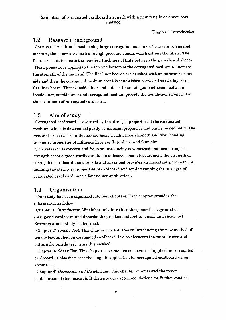
1.2 Research Background Corrugated medium is made using large corrugation machines. To create corrugated
medium, the paper is subjected to high pressure steam, which softens the fibers. The
fibers are bent to create the required thickness of flute between the paperboard sheets.
Next, pressure is applied to the top and bottom of the corrugated medium to increase
the strength of the material. The flat liner boards are brushed with an adhesive on one
side and then the corrugated medium sheet is sandwiched between the two layers of
flat liner board. That is inside liner and outside liner. Adequate adhesion between
inside liner, outside liner and corrugated medium provide the foundation strength for
the usefulness of corrugated cardboard.
1.3 Aim of study Corrugated cardboard is governed by the strength properties of the corrugated
medium, which is determined partly by material properties and partly by geometry. The
material properties of influence are basis weight, fiber strength and fiber bonding.
Geometry properties of influence here are flute shape and flute size.
This research is concern and focus on introducing new method and measuring the
strength of corrugated cardboard due to adhesive bond. Measurement the strength of
corrugated cardboard using tensile and shear test provides an important parameter in
defining the structural properties of cardboard and for determining the strength of
corrugated cardboard panels for end use applications.
1.4 Organization This study has been organized into four chapters. Each chapter provides the
information as follow:
Chapter 1: Introduction. We elaborately introduce the general background of
corrugated cardboard and describe the problems related to tensil and shear test.
Research aim of study is identified.
Chapter 2: Tensile Test. This chapter concentrates on introducing the new method of
tensile test applied on corrugated cardboard. It also discusses the suitable size and
pattern for tensile test using this method.
Chapter 3 Shear Test. This chapter concentrates on shear test applied on corrugated
cardboard. It also discusses the long life application for corrugated cardboard using
shear test.
Chapter 4: Discussion and Conclusions. This chapter summarized the major
contribution of this research. It then provides recommendations for further studies.
9

Estimation of corrugated cardboard strength with a new tensile or shear test method
Chapter 1 Introduction
1.5 References [1] Fiber Box Association. (1992). Fiber Box Handbook 20th ed. Fibre Box Association,
Rolling Meadows, IL, p.103
[211 Steenberg, B., Kubat, J. and Rudstrom, L. (1970). Competition in rigid packaging
materials. SvenskPapperstidh. 78(4):77-92
[3] Cofederation of Euiopean Paper Industries. (1998). 1998 Annual Statistics.
http://www.cepi.org/publications/jndex.htm
[4] International Corrugated Case Association. (2000). Annual Statistics- Corrugated
and Containerboard Production. http://www.iccanet.org/annual.htm
[5] Resource Information Systems, Inc (RISI). (1998). World Containerboard Study-
Forecast & Written Analysis.
[6] Gottshing, L., and Otto, W. (1976). Running characteristics of corrugating mediums
Part 1. Papier 30(6)221-228 (in German). Translation available from IPST, Atlanta,
GA.
[6]a. Gottshing, L., and Otto, W. (1976). Running characteristics of corrugating
mediums Part 2a. Papier 30(10)417-425 (in German). Translation available from
IPST, Atlanta, GA.
[71 Gottshing, L., and Otto, W. (1976). Running characteristics of corrugating mediums
Part 2b. Papier 30(11):457-465 (in German). Translation available from IPST,
Atlanta, GA.
[81 Gottshing, L., and Otto, W. (1977). Running characteristics of corrugating mediums
Part 3. Papier 31(2)4553 (in German). Translation available from IPST, Atlanta,
GA.
[9] Gottshing, L., and Otto, W (1977). Running characteristics of corrugating mediums
Part 4a. Papier 31(3)8594 (in German). Translation available from IPST, Atlanta,
GA.
[10] Gottshing, L., and Otto, W. (1977). Running characteristics df corrugating
mediums Part 4b. Papier 31(4):129-136 (in German). Translation available from
IPST, Atlanta, GA.
[ii] Gottshing, L., and Otto, W. (1977). Running characteristics of corrugating mediums
Part 5. Papier 31(5)169179 (in German). Translation available from IPST, Atlanta,
GA.
[12]WThitsitt, W J. (1987). Runnability and corrugating medium properties. Tappi
70(10) :99-103.
[13]Batelka, J. J. (1992). Development of green bond strength in the single facer. Tappi
75(10):94-101
10

Estimation of corrugated cardboard strength with a new tensile or shear test method
Chapter 1 Introduction
[141 Batelka, J. J. (1994). Development of green bond strength in the single facer. Part 2.
Tappi 75(10):94-101
[15]Bessen, A. H.(1999). The Corrugator. Jelmar, New York.
[16]Swec, L. (1986). Boxes, corrugated. In: The Wiley Encyclopedia of Packaging
Technology. M. Bakker, ed. Wiley, New York, p. 73.
[171 Jonson, G. (193). Corrugated Board Packaging. Pira mt., Leatherhead, England,
Chap. 14
[18]Huck, C. (1999). Customer demand drives mini-flute market. Paperboard Packag.
84 : (4) :30-40
[19] t- U (2oo9)J-'>—±, p4-7.
[20]Mark., Habeger., Borch., Lyne, (2002). Handbook of Physical Testing of Paper, Vol. 1
p564-575
11

alL
Estimation of corrugated cardboard strength with a new tensile or shear test method
Chapter 2 Tensile Test
Chapter 2 Tensile Test
2.1 Background Current Japan Industrial Standards WS) that is related to this study is stated as
below:
1. JIS P8113 Paper and board-Determination of tensile properties-Part 2: Constant
rate of elongation method [1]. This standard IS only tensile test for liner of
corrugated cardboard.
2. JIS K7113 Testing method for tensile properties of plastics. This standard IS
only tensile test for plastics.
3. JIS K6251 Rubber, vulcanized or thermoplastics- Determination of tensile
stress-strain properties 121. This IS only to determine the adhesive bond for
plastics.
2.2 Aim of Study Aim of this study is stated below:
1. To introduce a new method that is involved in specimen pattern and size of
tensile test apply on corrugated cardboard.
2. To study the adhesive bond on corrugated cardboard using the tensile test.
Fig. 1 shows the current problems when tensile test is applied on corrugated cardboard.
Problems that have been recognized are as follows:
1. size and pattern of specimen.
2. solves the problem at chuck position.
Fig. iCurrent problems of corrugated cardboard during tensile test (size, pattern of specimen and gripped zone).
Estimation of corrugated cardboard strength with a new tensile or shear test method
Chapter 2 Tensile Test
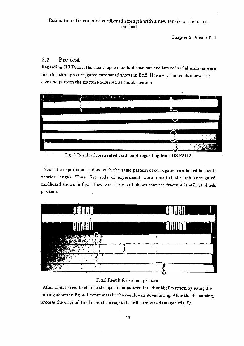
2.3 Pre-test Regarding JIS P8113, the size of specimen had been cut and two rods of aluminum were
inserted through corrugated cardboard shows in fig.2. However, the result shows the
size and pattern th6 fracture occurred at chuck position.
Fig. 2 Result of corrugated cardboard regarding from JIS P8113.
Next, the experiment is done with the same pattern of corrugated cardboard but with
shorter length. Thus, five rods of experiment were inserted through corrugated
cardboard shows in fig.3. However, the result shows that the fracture is still at chuck position.
Fig.3 Result for second pre-test.
After that, I tried to change the specimen pattern into dumbbell pattern by using die
cutting shows in fig. 4. Unfortunately, the result was devastating. After the die cutting,
process the original thickness of corrugated cardboard was damaged (fig. 5).
13

Estimation of corrugated cardboard strength with a new tensile or shear test method
Chapter 2 Tensile Test
Die
11
U VU LVLJ dUUUUUUUUUUUU cuiiuuuuuuin
.1•
Coter plate Mateii flow
Creasing rule
Knife / Ribber
Ij
Fig. 4 Die cutting processing
2.5mm
^052.5 - 2.18 mm
Fig. 5 Result after using die cutting and the thickness of corrugated cardboard after
deformed.
14

Estimation of corrugated cardboard strength with a new tensile or shear test method
Chapter 2 Tensile Test
A new instrument was designed in order to be used inside INSTRON (2716-015) shows
in fig. 6. The result after applying the new instrument in INSTRON (2716-015) is
showed in fig. 7. The end result failed to get not a deformed corrugated cardboard.
Fig. 6 The new instrument was designed and applied on INSTRON (2716-015).
1
INSTRON
(2716-015) new
instrument
Fig. 7esult after using Onew in 5).
In order, to get not deformed corrugated cardboard by using the new instrument, I
tried to insert rod of wood and plastic shows in fig. 8. However, by using both materials,
it is too hard to be cut by INSTRON (2716-015). The result was devastating
15

L AiAt POWERHead Kongsberg
ILI
* NSK
z1
T
Estimation of corrugated cardboard strength with a new tensile or shear test method
Chapter 2 Tensile Test
Fig. 8 Result after inserted rods of wood and plastic.
Finally, with the cooperation from Yoshizawa Company the specimen had successfully
been cut. By using 3 dimension cutting machine shows in fig. 9.
Fig. 9 The 3 dimension cutting machine.
16

Estimation of corrugated cardboard strength with a new tensile or shear test method
Chapter 2 Tensile Test
2.4Method 1
A flute was used as the material. The sectional properties material of A flute is shows
in fig. 10.
pitch, A=8.8mm
corrugated medflLin \ '' height '\JL i 14t = 5 mm
outside liner - I
Iflifli
machine direction I
Fig. 10 Sectional properties material of A flute.
2.4.1 Comparison between liner and corrugated cardboard
U The corrugated cardboard were been cut into size and pattern shows in fig. 11.
U Two rods of aluminum were inserted through the corrugated medium like fig. 11.
The size of rod of aluminum shows in fig. 12.
U Using INSTRON (2716015) to make the tensile test for corrugated cardboard (fig.
13). It was repeated for 10 times.
30mm 44 mm 30mm
*
Fig. 11 Size of specimen for dumbbell pattern of corrugated cardboard.
30mm
4 mmon
4
Fig. 12 Size of the rod of aluminum
17

uck
ck
Estimation of corrugated cardboard strength with a new tensile or shear test method
Chapter 2 Tensile Test
Fig. 13 specimen inside INSTRON (2716-015).
2.4.2 results
Fig. 14 shows the result for 10 times of tensile test on corrugated cardboard. The stress
of corrugated cardboard was calculated by eq. 1 for every method.
stress = (load) / (thickness) X (2 liner) eq. (1)
tig. 14 itesuit 01 corrugatect carcttoarct on tensile test
18

Estimation of corrugated cardboard strength with a new tensile or shear test method
Chapter 2 Tensile Test
Fig. 14 shows that two patterns of graphs were achieved during tensile test on
corrugated cardboard. The average yield breaking was 56.3 MPa and the average strain
breaking was 1.7%. 1st pattern of graph is without the effect of corrugated medium. 2nd
pattern of graph is with the effect of corrugated medium. 1st pattern of graph (fig. 15)
and 2nd pattern of graph (fig. 16) shows the detail for every pattern of graph.
70
—linel
60
line2
40 - _____ —line3
30 - - —line4
20line6
line9
0.0% 0.5% 1.0% 1.5% 2.0% 2.5% 3.0% strain
Fig. 15 The result for 1st pattern of graph
From fig. 15, the average yield breaking *as 57.3 MPa and average strain breaking
was 1.8%. 6 among 10 times of result were this pattern.
19

Estimation of corrugated cardboard strength with a new tensile or shear test method
Chapter 2 Tensile Test
70.0
—line
60.0 5
50.0 * _____
—line
40.0
30.0—line
8
20.0
10.0 - - —line 10
0.0 0.0% 0.5% 1.0% .1.5% 2.0% 2.5% 3.0% strain
Fig. 16 The result for 1st pattern of graph
From fig. 16, the average yield breaking was 54.8 MPa and average strain breaking
was 1.8%. 4 among 10 times of result were this pattern. This shows that for the average
yield breaking the 1st pattern of graph was bigger than the Did pattern of graph.
However, the average strain breaking for both patterns was the same. Next, fig. 17 to fig.
20 was the result pictures for 1st pattern of graph (line 1) from fig. 15.
-. - Fig. 17 line 1 &om
___________
20

Estimation of corrugated cardboard strength with a new tensile or shear test method
Chapter 2 Tensile Test
FE. flIE 1;
5-Inm hI1
Fig. 18 line 1 from left view.
C=—5mm
:t I
Fig. 19 line rom upper view.
1 I 5mm I
Fig. 20 line 1 from below view.
Fig. 17 and fig. 18 show that the fracture occurred at both; inside and outside liner.
Thus both results show that fracture occurred far from the adhesive bond. Fig. 19 and
fig. 20 show the result that fracture occurred not in the straight line. This is because the
effect of corrugated medium does not appear. This result also shows the same pattern of
fracture if we apply tensile test on liner on 45 degree. Fig. 21 to fig. 24 is the result of
the pictures for 2nd pattern of graph (line 5) from fig. 15.
jnim -
of 0
-. . - ----2' - ---- 1'•. .,. -
Fig. 21 line 5 from right view.
21