Embed Size (px)
Citation preview
2.0 PROJECT DESCRIPTION
2.1 OVERVIEW OF PIPELINE SYSTEM
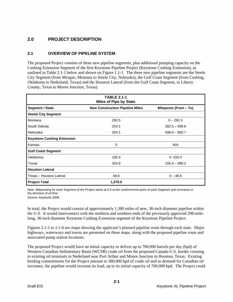
The proposed Project consists of three new pipeline segments, plus additional pumping capacity on the Cushing Extension Segment of the first Keystone Pipeline Project (Keystone Cushing Extension), as outlined in Table 2.1-1 below and shown on Figure 1.1-1. The three new pipeline segments are the Steele City Segment (from Morgan, Montana to Steele City, Nebraska), the Gulf Coast Segment (from Cushing, Oklahoma to Nederland, Texas) and the Houston Lateral (from the Gulf Coast Segment, in Liberty County, Texas to Moore Junction, Texas).
TABLE 2.1-1 Miles of Pipe by State
Segment / State New Construction Pipeline Miles Mileposts (From – To)
Steele City Segment
Montana 282.5 0 – 282.5
South Dakota 314.1 282.5 – 596.6
Nebraska 254.1 596.6 – 850.7
Keystone Cushing Extension
Kansas 0 N/A
Gulf Coast Segment
Oklahoma 155.4 0 -155.4
Texas 324.8 155.4 – 480.2
Houston Lateral
Texas – Houston Lateral 48.6 0 – 48.6
Project Total 1,379.5
Note: Mileposting for each Segment of the Project starts at 0.0 at the northernmost point of each Segment and increases in the direction of oil flow.
Source: Keystone 2008.
In total, the Project would consist of approximately 1,380 miles of new, 36-inch diameter pipeline within the U.S. It would interconnect with the northern and southern ends of the previously approved 298-mile-long, 36-inch diameter Keystone Cushing Extension segment of the Keystone Pipeline Project.
Figures 2.1-1 to 2.1-6 are maps showing the applicant’s planned pipeline route through each state. Major highways, waterways and towns are presented on these maps, along with the proposed pipeline route and associated pump station locations.
The proposed Project would have an initial capacity to deliver up to 700,000 barrels per day (bpd) of Western Canadian Sedimentary Basin (WCSB) crude oil from the proposed Canada-U.S. border crossing to existing oil terminals in Nederland near Port Arthur and Moore Junction in Houston, Texas. Existing binding commitments for the Project amount to 380,000 bpd of crude oil and as demand for Canadian oil increases, the pipeline would increase its load, up to its initial capacity of 700,000 bpd. The Project could
2-1 Draft EIS Keystone XL Pipeline Project
ultimately transport up to 900,000 bpd of crude oil through the proposed pipeline by adding additional pumping capacity if warranted by future market demand.
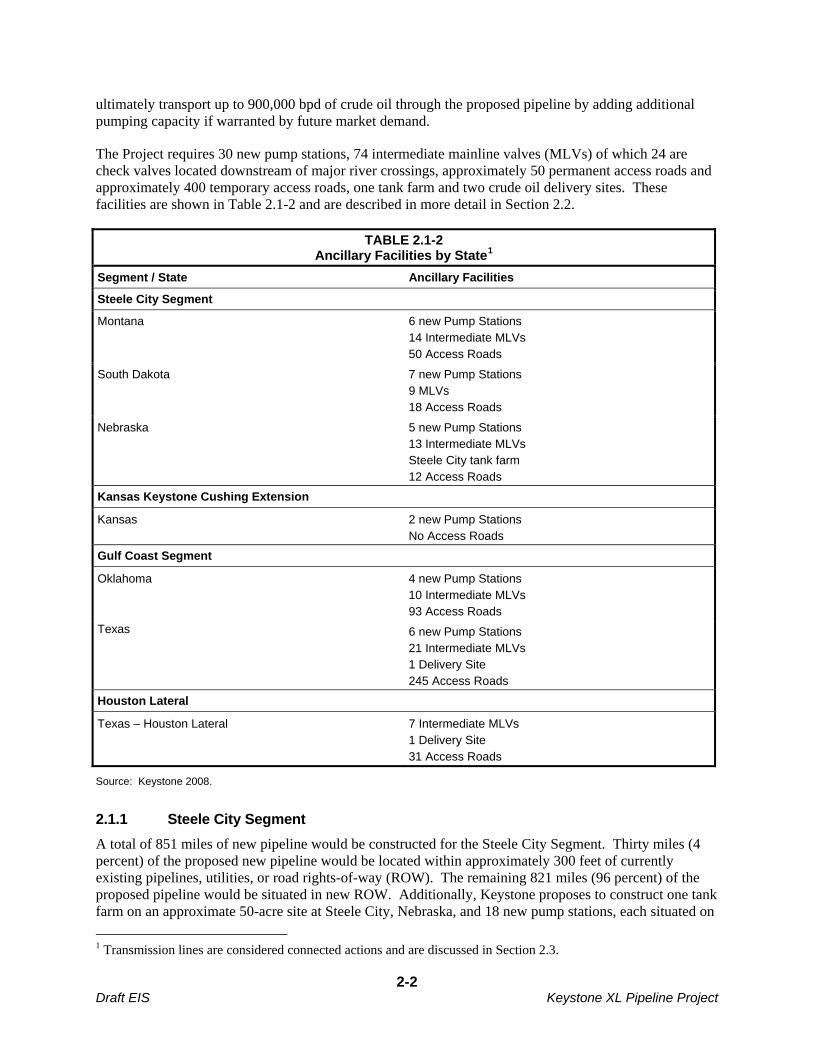
The Project requires 30 new pump stations, 74 intermediate mainline valves (MLVs) of which 24 are check valves located downstream of major river crossings, approximately 50 permanent access roads and approximately 400 temporary access roads, one tank farm and two crude oil delivery sites. These facilities are shown in Table 2.1-2 and are described in more detail in Section 2.2.
TABLE 2.1-2 Ancillary Facilities by State1
Segment / State Ancillary Facilities
Steele City Segment
Montana 6 new Pump Stations 14 Intermediate MLVs 50 Access Roads
South Dakota 7 new Pump Stations 9 MLVs 18 Access Roads
Nebraska 5 new Pump Stations 13 Intermediate MLVs Steele City tank farm 12 Access Roads
Kansas Keystone Cushing Extension
Kansas 2 new Pump Stations No Access Roads
Gulf Coast Segment
Oklahoma 4 new Pump Stations 10 Intermediate MLVs 93 Access Roads
Texas 6 new Pump Stations 21 Intermediate MLVs 1 Delivery Site 245 Access Roads
Houston Lateral
Texas – Houston Lateral 7 Intermediate MLVs 1 Delivery Site 31 Access Roads
Source: Keystone 2008.
2.1.1 Steele City Segment
A total of 851 miles of new pipeline would be constructed for the Steele City Segment. Thirty miles (4 percent) of the proposed new pipeline would be located within approximately 300 feet of currently existing pipelines, utilities, or road rights-of-way (ROW). The remaining 821 miles (96 percent) of the proposed pipeline would be situated in new ROW. Additionally, Keystone proposes to construct one tank farm on an approximate 50-acre site at Steele City, Nebraska, and 18 new pump stations, each situated on
1 Transmission lines are considered connected actions and are discussed in Section 2.3.
2-2 Draft EIS Keystone XL Pipeline Project

a 5-acre site. New electrical transmission power lines with voltage of between 69 kV to 240 kV would be constructed and operated by local power providers to service pump stations and a tank farm along the proposed Project route. These are discussed as connected actions in Section 2.5.
Lands affected during the construction phase of the Steele City Segment amount to approximately 14,595 acres. Of this acreage, approximately 5,351 acres would be permanently altered for use during the operational phase of Project.
2.1.2 Cushing Extension (New Pump Stations)
Two new pump stations would be constructed in Kansas along the previously permitted Keystone Pipeline’s Cushing Extension. These pump stations would enable the proposed Project to maintain the pressure required to make crude oil deliveries at desired throughput volumes. The two new pump stations would disturb approximately 12 acres of land during both the construction and operational phases of the Project.
2.1.3 Gulf Coast Segment and Houston Lateral
A total of 480 miles of new pipeline is required for the Gulf Coast Segment of the proposed Project. Of these, 393 miles (82 percent) would be located within approximately 300 feet of existing pipelines, utilities, or road ROWs. The remaining 87 miles (18 percent) of the pipeline would be situated in new ROW. The Houston Lateral comprises 49 miles of new pipeline, 20 miles (41 percent) of which would be located within approximately 300 feet of existing pipelines, utilities, or road ROWs. The remaining 29 miles (59 percent) would be situated in new ROW.
Approximately 9,161 acres of land would be affected during construction of the Gulf Coast and Houston Lateral segments combined. Of this, 3,374 acres would be affected during Project operation.
Ten new pump stations would be constructed on the Gulf Coast Segment, each situated on a 5-acre site. Keystone would also install two delivery facilities along the proposed Project route, one at Nederland and one at Moore Junction, Texas.
2.1.4 Land and Borrow Material Requirements
2.1.4.1 Land Requirements
The pipeline would require a 110-foot wide construction ROW, consisting of a 60-foot temporary easement and a 50-foot permanent easement. In certain sensitive areas, which may include wetlands, cultural sites, shelterbelts, residential areas, or commercial/industrial areas, the construction ROW would be reduced to 85 feet.
Figure 2.1.4-1 illustrates typical construction in locations that would not parallel an existing pipeline corridor or other linear facility. Figures 2.1.4-2 and 2.1.4-3 illustrate the typical construction ROW and equipment work locations in areas where the pipeline would parallel an existing linear feature.
Approximately 23,768 acres of land would be disturbed during the construction of the proposed facilities. Surface disturbance associated with construction and operation of the proposed Project is summarized in Table 2.1.4-1.
After construction, the temporary ROW (15,031 acres) would be restored consistent with federal and state regulations as applicable and the easement agreements negotiated between Keystone and individual landowners or land managers. The permanent ROW for the pipeline amounts to approximately 8,749
2-3 Draft EIS Keystone XL Pipeline Project
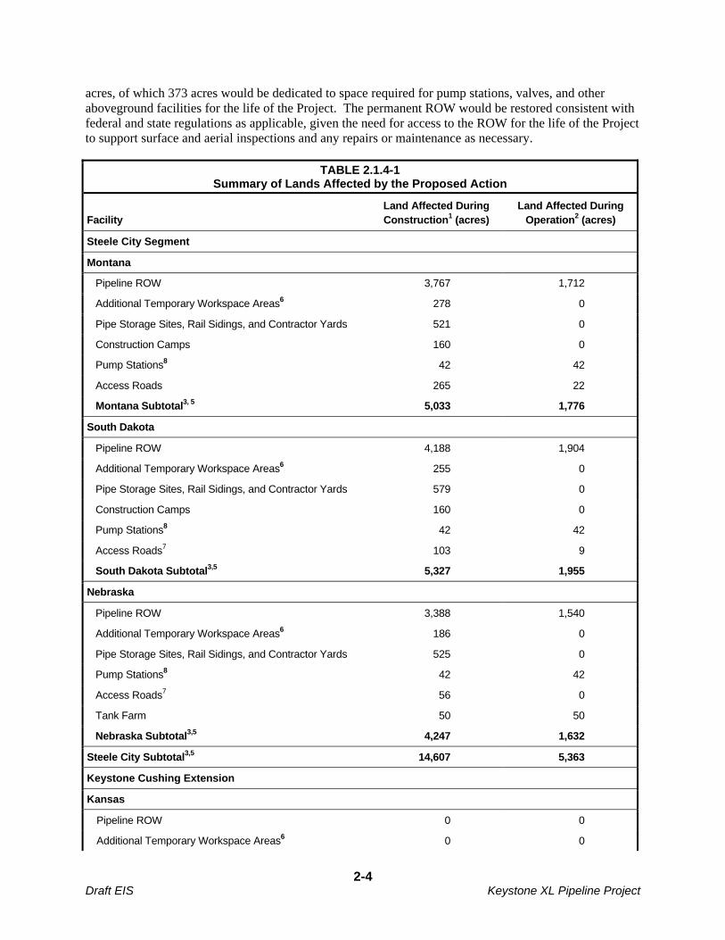
acres, of which 373 acres would be dedicated to space required for pump stations, valves, and other aboveground facilities for the life of the Project. The permanent ROW would be restored consistent with federal and state regulations as applicable, given the need for access to the ROW for the life of the Project to support surface and aerial inspections and any repairs or maintenance as necessary.
TABLE 2.1.4-1 Summary of Lands Affected by the Proposed Action
Facility Land Affected During Construction1 (acres)
Land Affected During Operation2 (acres)
Steele City Segment
Montana
Pipeline ROW 3,767 1,712
Additional Temporary Workspace Areas6 278 0
Pipe Storage Sites, Rail Sidings, and Contractor Yards 521 0
Construction Camps 160 0
Pump Stations8 42 42
Access Roads 265 22
Montana Subtotal3, 5 5,033 1,776
South Dakota
Pipeline ROW 4,188 1,904
Additional Temporary Workspace Areas6 255 0
Pipe Storage Sites, Rail Sidings, and Contractor Yards 579 0
Construction Camps 160 0
Pump Stations8 42 42
Access Roads7 103 9
South Dakota Subtotal3,5 5,327 1,955
Nebraska
Pipeline ROW 3,388 1,540
Additional Temporary Workspace Areas6 186 0
Pipe Storage Sites, Rail Sidings, and Contractor Yards 525 0
Pump Stations8 42 42
Access Roads7 56 0
Tank Farm 50 50
Nebraska Subtotal3,5 4,247 1,632
Steele City Subtotal3,5 14,607 5,363
Keystone Cushing Extension
Kansas
Pipeline ROW 0 0
Additional Temporary Workspace Areas6 0 0
2-4 Draft EIS Keystone XL Pipeline Project
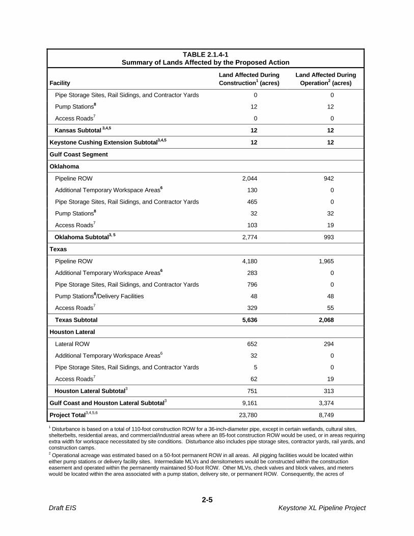
TABLE 2.1.4-1 Summary of Lands Affected by the Proposed Action
Facility Land Affected During Construction1 (acres)
Land Affected During Operation2 (acres)
Pipe Storage Sites, Rail Sidings, and Contractor Yards 0 0
Pump Stations8 12 12
Access Roads7 0 0
Kansas Subtotal 3,4,5 12 12
Keystone Cushing Extension Subtotal3,4,5 12 12
Gulf Coast Segment
Oklahoma
Pipeline ROW 2,044 942
Additional Temporary Workspace Areas6 130 0
Pipe Storage Sites, Rail Sidings, and Contractor Yards 465 0
Pump Stations8 32 32
Access Roads7 103 19
Oklahoma Subtotal3, 5 2,774 993
Texas
Pipeline ROW 4,180 1,965
Additional Temporary Workspace Areas6 283 0
Pipe Storage Sites, Rail Sidings, and Contractor Yards 796 0
Pump Stations8/Delivery Facilities 48 48
Access Roads7 329 55
Texas Subtotal 5,636 2,068
Houston Lateral
Lateral ROW 652 294
Additional Temporary Workspace Areas6 32 0
Pipe Storage Sites, Rail Sidings, and Contractor Yards 5 0
Access Roads7 62 19
Houston Lateral Subtotal3 751 313
Gulf Coast and Houston Lateral Subtotal3 9,161 3,374
Project Total3,4,5,6 23,780 8,749
1 Disturbance is based on a total of 110-foot construction ROW for a 36-inch-diameter pipe, except in certain wetlands, cultural sites, shelterbelts, residential areas, and commercial/industrial areas where an 85-foot construction ROW would be used, or in areas requiring extra width for workspace necessitated by site conditions. Disturbance also includes pipe storage sites, contractor yards, rail yards, and construction camps. 2 Operational acreage was estimated based on a 50-foot permanent ROW in all areas. All pigging facilities would be located within either pump stations or delivery facility sites. Intermediate MLVs and densitometers would be constructed within the construction easement and operated within the permanently maintained 50-foot ROW. Other MLVs, check valves and block valves, and meters would be located within the area associated with a pump station, delivery site, or permanent ROW. Consequently, the acres of
2-5 Draft EIS Keystone XL Pipeline Project

disturbance for these aboveground facilities are captured within the Pipeline ROW and Pump Station/Delivery Facilities categories within the table. 3 Discrepancies in total acreages are due to rounding. 4 Disturbance associated with the Keystone Cushing Extension in this table is for the two new pump stations to be constructed for this Project. For discussion of previously permitted disturbance associated with the construction of the Keystone Cushing Extension see TransCanada (2006). 5 Includes disturbances associated with construction of the Steele City Segment, the Gulf Coast Segment, and the Houston Lateral. This total includes 12 acres associated with construction and operation of new pump stations along the Keystone Cushing Extension. 6 Includes staging areas of approximately 5 acres. Does not include the potential for extended additional Temporary Workspace Areas necessary for construction in rough terrain or in unstable soils. These locations are currently undergoing identification and analysis. 7 Access road temporary and permanent disturbance is based on 30-foot width; all non-public roads are conservatively estimated to require upgrades and maintenance during construction.
8 This does not include the associated transmission lines required for pump stations. For information on these, please refer to Table
2.3.1-1.
Source: Keystone 2009c.
2.1.4.2 Borrow Material Requirements
Borrow material would be required for temporary sites (such as storage sites, contractor yards, temporary access roads and access pads at ROW road crossings); to stabilize the land for permanent facilities (including pump stations, valve sites, and permanent access roads); and for padding the pipeline trench bottom as needed. Table 2.1.4-2 shows the amount of borrow material that would be required in each state.
TABLE 2.1.4-2 Borrow Material Requirements by State
State Cubic Yards
Montana 206,536
South Dakota 193,268
Nebraska 162,097
Kansas1 9,260
Oklahoma 123,002
Texas2 372,042
TOTAL 1,066,205
1 Two Keystone XL pump stations. 2 Includes Houston Lateral.
Pipe storage sites and contractor yards would require some gravel placement. All borrow material would be obtained from an existing, previously permitted commercial source located as close to the pipe or contractor yard as possible. An estimated 7,000 cubic yards of gravel would be required for each pipe storage site. For the proposed 39 storage sites, a total of approximately 273,000 cubic yards of gravel would be required. In addition, an estimated 4,600 cubic yards of gravel would be required for each contractor yard. For the 28 contractor yards proposed, a total of approximately 130,000 cubic yards of gravel would be needed. Surveys of pipe storage sites, railroad sidings and contractor yards would be completed prior to construction.
Approximately 400 temporary access roads for construction would be needed, requiring approximately 37,500 cubic yards of gravel for access pads and culverts. Access pads would be placed at ROW
2-6 Draft EIS Keystone XL Pipeline Project
crossings of public and private roads, requiring a total of about 88,000 cubic yards of gravel. Approximately 1,590 such road crossings are proposed.
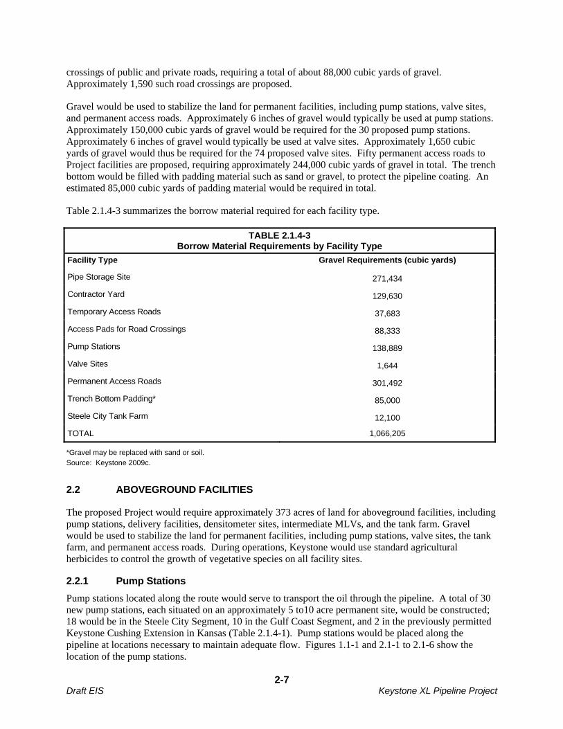
Gravel would be used to stabilize the land for permanent facilities, including pump stations, valve sites, and permanent access roads. Approximately 6 inches of gravel would typically be used at pump stations. Approximately 150,000 cubic yards of gravel would be required for the 30 proposed pump stations. Approximately 6 inches of gravel would typically be used at valve sites. Approximately 1,650 cubic yards of gravel would thus be required for the 74 proposed valve sites. Fifty permanent access roads to Project facilities are proposed, requiring approximately 244,000 cubic yards of gravel in total. The trench bottom would be filled with padding material such as sand or gravel, to protect the pipeline coating. An estimated 85,000 cubic yards of padding material would be required in total.
Table 2.1.4-3 summarizes the borrow material required for each facility type.
TABLE 2.1.4-3 Borrow Material Requirements by Facility Type
Facility Type Gravel Requirements (cubic yards)
Pipe Storage Site 271,434
Contractor Yard 129,630
Temporary Access Roads 37,683
Access Pads for Road Crossings 88,333
Pump Stations 138,889
Valve Sites 1,644
Permanent Access Roads 301,492
Trench Bottom Padding* 85,000
Steele City Tank Farm 12,100
TOTAL 1,066,205
*Gravel may be replaced with sand or soil.
Source: Keystone 2009c.
2.2 ABOVEGROUND FACILITIES
The proposed Project would require approximately 373 acres of land for aboveground facilities, including pump stations, delivery facilities, densitometer sites, intermediate MLVs, and the tank farm. Gravel would be used to stabilize the land for permanent facilities, including pump stations, valve sites, the tank farm, and permanent access roads. During operations, Keystone would use standard agricultural herbicides to control the growth of vegetative species on all facility sites.
2.2.1 Pump Stations
Pump stations located along the route would serve to transport the oil through the pipeline. A total of 30 new pump stations, each situated on an approximately 5 to10 acre permanent site, would be constructed; 18 would be in the Steele City Segment, 10 in the Gulf Coast Segment, and 2 in the previously permitted Keystone Cushing Extension in Kansas (Table 2.1.4-1). Pump stations would be placed along the pipeline at locations necessary to maintain adequate flow. Figures 1.1-1 and 2.1-1 to 2.1-6 show the location of the pump stations.
2-7 Draft EIS Keystone XL Pipeline Project

Each new pump station would consist of up to six pumps driven by electric motors, an electrical building, an electrical substation, two sump tanks, a remotely operated intermediate MLV, a communication tower, a small maintenance building, and a parking area for station maintenance personnel. Stations would operate on locally purchased electric power and would be fully automated for unmanned operation.
The pump stations would have an uninterruptible power supply (UPS) for all communication and specific control equipment in the case of a power failure. No backup generators at pump stations are planned and, therefore, no fuel storage tanks would be located at pump stations. Communication towers at pump stations generally would be approximately 33 feet in height, but antenna height at select pump stations may be taller as determined upon completion of a detailed engineering study. In no event would antennae exceed a maximum height of 190 feet.
The pipe entering and exiting the pump station sites would be located below grade. The pipe manifolding connected with the pump stations would be aboveground.
2.2.2 Mainline Valves
Keystone proposes to construct 74 intermediate MLV sites along the new pipeline ROW and at each pump station. When not located at a pump station, intermediate MLVs would be sectionalizing block valves (valves that divide up the pipeline into smaller segments that can be isolated in order to minimize and contain the effects of a line rupture) constructed within a fenced 30-foot by 40-foot site located on the permanent easement.
Remotely operated intermediate MLVs would be located at pump stations, at major river crossings, upstream of sensitive waterbodies and at other locations. These remotely operated valves can be activated to shut down the pipeline in the event of an emergency to minimize environmental impacts in the unlikely event of a spill. The remotely operated valves have sufficient backup power to maintain communication readings in the event of power loss. Proposed intermediate MLV locations were determined by the locations of pump stations, hydraulic profile considerations, DOT regulations, and environmental and safety concerns. Table 2.2.2-1 provides the locations of intermediate MLVs.
TABLE 2.2.2-1 Intermediate Mainline Valve Locations
Mainline Valve ID Approximate
Milepost Associated Facilities Land
Ownership Land Use
Steele City Segment
MLV-01 20.27 Motor Operated Valve Site Private Grassland/Rangeland
CK-MLV-02 28.14 Check and Manual Valve Site Private Agricultural/Cropland
MLV-03 63.51 Motor Operated Valve Site Private Grassland/Rangeland
CK-MLV-04 71.68 Check and Manual Valve Site Private Agricultural/Cropland
MLV-05 81.21 Motor Operated Valve Site Private Agricultural/Cropland
CK-MLV-06 83.82 Check and Manual Valve Site Private Agricultural/Cropland
CK-MLV-07 90.83 Check and Manual Valve site BLM Grassland/ Rangeland
MLV-08 122.83 Motor Operated Valve Site Private Agricultural/Cropland
MLV-09 177.67 Motor Operated Valve Site Private Grassland/Rangeland
MLV-10 194.06 Motor Operated Valve Site Private Agricultural/Cropland
CK-MLV-11 203.21 Check and Manual Valve Site Private Agricultural/Cropland
MLV-12 227.43 Motor Operated Valve Site Private Agricultural/Cropland
2-8 Draft EIS Keystone XL Pipeline Project
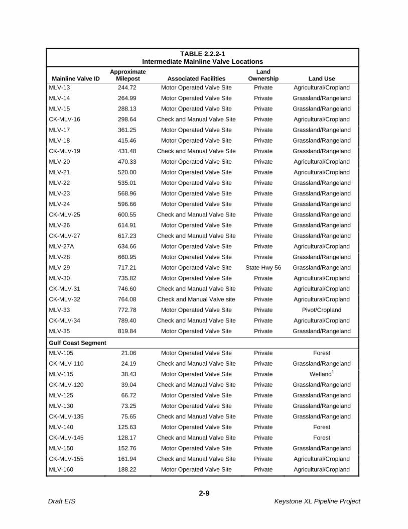
TABLE 2.2.2-1 Intermediate Mainline Valve Locations
Mainline Valve ID Approximate
Milepost Associated Facilities Land
Ownership Land Use
MLV-13 244.72 Motor Operated Valve Site Private Agricultural/Cropland
MLV-14 264.99 Motor Operated Valve Site Private Grassland/Rangeland
MLV-15 288.13 Motor Operated Valve Site Private Grassland/Rangeland
CK-MLV-16 298.64 Check and Manual Valve Site Private Agricultural/Cropland
MLV-17 361.25 Motor Operated Valve Site Private Grassland/Rangeland
MLV-18 415.46 Motor Operated Valve Site Private Grassland/Rangeland
CK-MLV-19 431.48 Check and Manual Valve Site Private Grassland/Rangeland
MLV-20 470.33 Motor Operated Valve Site Private Agricultural/Cropland
MLV-21 520.00 Motor Operated Valve Site Private Agricultural/Cropland
MLV-22 535.01 Motor Operated Valve Site Private Grassland/Rangeland
MLV-23 568.96 Motor Operated Valve Site Private Grassland/Rangeland
MLV-24 596.66 Motor Operated Valve Site Private Grassland/Rangeland
CK-MLV-25 600.55 Check and Manual Valve Site Private Grassland/Rangeland
MLV-26 614.91 Motor Operated Valve Site Private Grassland/Rangeland
CK-MLV-27 617.23 Check and Manual Valve Site Private Grassland/Rangeland
MLV-27A 634.66 Motor Operated Valve Site Private Agricultural/Cropland
MLV-28 660.95 Motor Operated Valve Site Private Grassland/Rangeland
MLV-29 717.21 Motor Operated Valve Site State Hwy 56 Grassland/Rangeland
MLV-30 735.82 Motor Operated Valve Site Private Agricultural/Cropland
CK-MLV-31 746.60 Check and Manual Valve Site Private Agricultural/Cropland
CK-MLV-32 764.08 Check and Manual Valve site Private Agricultural/Cropland
MLV-33 772.78 Motor Operated Valve Site Private Pivot/Cropland
CK-MLV-34 789.40 Check and Manual Valve Site Private Agricultural/Cropland
MLV-35 819.84 Motor Operated Valve Site Private Grassland/Rangeland
Gulf Coast Segment
MLV-105 21.06 Motor Operated Valve Site Private Forest
CK-MLV-110 24.19 Check and Manual Valve Site Private Grassland/Rangeland
MLV-115 38.43 Motor Operated Valve Site Private Wetland1
CK-MLV-120 39.04 Check and Manual Valve Site Private Grassland/Rangeland
MLV-125 66.72 Motor Operated Valve Site Private Grassland/Rangeland
MLV-130 73.25 Motor Operated Valve Site Private Grassland/Rangeland
CK-MLV-135 75.65 Check and Manual Valve Site Private Grassland/Rangeland
MLV-140 125.63 Motor Operated Valve Site Private Forest
CK-MLV-145 128.17 Check and Manual Valve Site Private Forest
MLV-150 152.76 Motor Operated Valve Site Private Grassland/Rangeland
CK-MLV-155 161.94 Check and Manual Valve Site Private Agricultural/Cropland
MLV-160 188.22 Motor Operated Valve Site Private Agricultural/Cropland
2-9 Draft EIS Keystone XL Pipeline Project
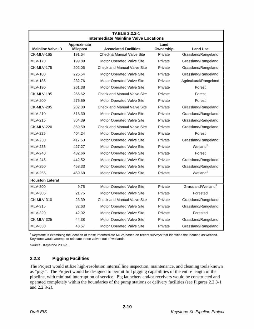
TABLE 2.2.2-1 Intermediate Mainline Valve Locations
Mainline Valve ID Approximate
Milepost Associated Facilities Land
Ownership Land Use
CK-MLV-165 191.64 Check & Manual Valve Site Private Grassland/Rangeland
MLV-170 199.89 Motor Operated Valve Site Private Grassland/Rangeland
CK-MLV-175 202.05 Check and Manual Valve Site Private Grassland/Rangeland
MLV-180 225.54 Motor Operated Valve Site Private Grassland/Rangeland
MLV-185 232.76 Motor Operated Valve Site Private Agricultural/Rangeland
MLV-190 261.38 Motor Operated Valve Site Private Forest
CK-MLV-195 266.62 Check and Manual Valve Site Private Forest
MLV-200 276.59 Motor Operated Valve Site Private Forest
CK-MLV-205 282.80 Check and Manual Valve Site Private Grassland/Rangeland
MLV-210 313.30 Motor Operated Valve Site Private Grassland/Rangeland
MLV-215 364.39 Motor Operated Valve Site Private Grassland/Rangeland
CK-MLV-220 369.59 Check and Manual Valve Site Private Grassland/Rangeland
MLV-225 404.24 Motor Operated Valve Site Private Forest
MLV-230 417.53 Motor Operated Valve Site Private Grassland/Rangeland
MLV-235 427.27 Motor Operated Valve Site Private Wetland1
MLV-240 432.66 Motor Operated Valve Site Private Forest
MLV-245 442.52 Motor Operated Valve Site Private Grassland/Rangeland
MLV-250 458.33 Motor Operated Valve Site Private Grassland/Rangeland
MLV-255 469.68 Motor Operated Valve Site Private Wetland1
Houston Lateral
MLV-300 9.75 Motor Operated Valve Site Private Grassland/Wetland1
MLV-305 21.75 Motor Operated Valve Site Private Forested
CK-MLV-310 23.39 Check and Manual Valve Site Private Grassland/Rangeland
MLV-315 32.63 Motor Operated Valve Site Private Grassland/Rangeland
MLV-320 42.92 Motor Operated Valve Site Private Forested
CK-MLV-325 44.38 Motor Operated Valve Site Private Grassland/Rangeland
MLV-330 48.57 Motor Operated Valve Site Private Grassland/Rangeland
1 Keystone is examining the location of these intermediate MLVs based on recent surveys that identified the location as wetland. Keystone would attempt to relocate these valves out of wetlands.
Source: Keystone 2009c.
2.2.3 Pigging Facilities
The Project would utilize high-resolution internal line inspection, maintenance, and cleaning tools known as “pigs”. The Project would be designed to permit full pigging capabilities of the entire length of the pipeline, with minimal interruption of service. Pig launchers and/or receivers would be constructed and operated completely within the boundaries of the pump stations or delivery facilities (see Figures 2.2.3-1 and 2.2.3-2).
2-10 Draft EIS Keystone XL Pipeline Project
2.2.4 Densitometer Facilities
Densitometer facilities on the proposed pipeline would be equipped with densitometer/viscometer analyzers which measure the density of the product prior to delivery. Densitometer information would be incorporated into quality and custody metering located at all injection points into Keystone and at all delivery points.
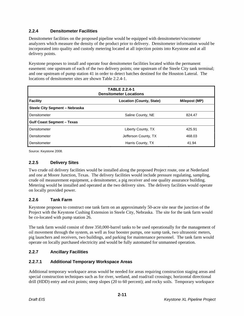
Keystone proposes to install and operate four densitometer facilities located within the permanent easement: one upstream of each of the two delivery points; one upstream of the Steele City tank terminal; and one upstream of pump station 41 in order to detect batches destined for the Houston Lateral. The locations of densitometer sites are shown Table 2.2.4-1.
TABLE 2.2.4-1 Densitometer Locations
Facility Location (County, State) Milepost (MP)
Steele City Segment – Nebraska
Densitometer Saline County, NE 824.47
Gulf Coast Segment – Texas
Densitometer Liberty County, TX 425.91
Densitometer Jefferson County, TX 468.03
Densitometer Harris County, TX 41.94
Source: Keystone 2008.
2.2.5 Delivery Sites
Two crude oil delivery facilities would be installed along the proposed Project route, one at Nederland and one at Moore Junction, Texas. The delivery facilities would include pressure regulating, sampling, crude oil measurement equipment, a densitometer, a pig receiver and one quality assurance building. Metering would be installed and operated at the two delivery sites. The delivery facilities would operate on locally provided power.
2.2.6 Tank Farm
Keystone proposes to construct one tank farm on an approximately 50-acre site near the junction of the Project with the Keystone Cushing Extension in Steele City, Nebraska. The site for the tank farm would be co-located with pump station 26.
The tank farm would consist of three 350,000-barrel tanks to be used operationally for the management of oil movement through the system, as well as four booster pumps, one sump tank, two ultrasonic meters, pig launchers and receivers, two buildings, and parking for maintenance personnel. The tank farm would operate on locally purchased electricity and would be fully automated for unmanned operation.
2.2.7 Ancillary Facilities
2.2.7.1 Additional Temporary Workspace Areas
Additional temporary workspace areas would be needed for areas requiring construction staging areas and special construction techniques such as for river, wetland, and road/rail crossings; horizontal directional drill (HDD) entry and exit points; steep slopes (20 to 60 percent); and rocky soils. Temporary workspace
2-11 Draft EIS Keystone XL Pipeline Project

areas would be located at the prescribed setback distance from wetland and waterbody features as determined on a site-specific basis. The location of additional temporary workspace areas would be adjusted as the Project continues to be refined.
Dimensions and acreage of typical additional temporary workspace areas are shown in Table 2.2.7-1.
TABLE 2.2.7-1 Dimensions and Acreage of Typical Additional Temporary Workspace Areas
Feature
Dimensions (length by width in feet at each
side of crossing) Acreage
Waterbodies traversed via HDD 250 x 150, as well as the length of the drill plus 150 x 150 on exit side
1.4
Waterbodies > 50 feet wide 300 x 100 0.7
Waterbodies < 50 feet wide 150 x 25 on working and spoil sides
or 150 x 50 on working side only
0.2
Bored highways and railroads 175 x 25 on working and spoil sides
or 175 x 50 on working side only
0.2
Open-cut or bored county or private roads
125 x 25 on working and spoil sidesor 125 x 50 on working side only
0.1
Foreign pipeline/utility/other buried feature crossings
125 x 50 0.1
Push-pull wetland crossings 50 feet x length of wetland Varies
Construction spread mobilization and demobilization
470 x 470 5.1
Stringing truck turnaround areas 200 x 80 0.4
Source: Keystone 2009c.
2.2.7.2 Pipe Storage Sites, Railroad Sidings and Contractor Yards
Extra workspace areas away from the construction ROW would be required during construction of the Project for use as pipe storage sites, railroad sidings and contractor yards. Pipe storage sites would be required at 30-mile to 80-mile intervals and contractor yards would be required at approximately 60-mile intervals. It is estimated that 40 pipe storage yards and 19 contractor yards would be required for the proposed Project. Table 2.2.7-2 provides the locations and acreage of potential pipe storage yards and contractor yards.
TABLE 2.2.7-2 Locations and Acreage of Potential Pipe Storage Sites, Railroad Sidings,
and Contractors Yards
State/Type of Yard Counties Combined Acreage1
Montana
Contractor Yards (5) Dawson, Fallon, McCone, Valley (2) 152
Railroad Siding (5)2 Valley, Fallon, Roosevelt, Dawson (2) 100
2-12 Draft EIS Keystone XL Pipeline Project

TABLE 2.2.7-2 Locations and Acreage of Potential Pipe Storage Sites, Railroad Sidings,
and Contractors Yards
State/Type of Yard Counties Combined Acreage1
Pipe Storage Sites (9) Phillips, Valley (2), McCone (2), Dawson (2), Fallon (2) 269
South Dakota
Contractor Yards (5) Gregory, Haakon, Harding, Meade, Jones 151
Railroad Siding (5)2 Butte, Pennington (2), Stanley, Hutchinson 100
Pipe Storage Sites (11) Harding (3), Meade (2), Haakon (2), Jones (2), Tripp (2) 328
Nebraska
Contractor Yards (7) Gage, Holt (2), York, Jefferson, Merrick, Greeley 191
Railroad Siding (3)2 Merrick, York, Jefferson 60
Pipe Storage Sites (9) Keya Paha, Holt, Wheeler, Greeley, Nance, Hamilton, Fillmore, Jefferson (2)
274
Kansas
Contractor Yards None 0
Pipe Storage Sites None 0
Oklahoma
Contractor Yards (1) Hughes 27
Railroad Siding (3)2 Grady, Pittsburg, Pottawatomie 110
Pipe Storage Sites (3) Lincoln, Grady, Bryan 328
Texas
Contractor Yards (10) Liberty, Lamar (2), Angelina (2), Houston, Nacogdoches, Jefferson, Titus, Rusk
154
Railroad Sidings (5)2 Lamar, Angelina, Hardin, Titus (2) 28
Pipe Storage Sites (7) Smith, Orange, Jefferson, Fannin, Lamar, Polk (2) 619
1 Land use of these sites is currently under evaluation. The final acreage may be reduced to avoid biological or cultural resources, if any are identified. 2 Estimated size and location.
Source: Keystone 2009c.
Pipe storage sites along the pipeline route would occupy approximately 30 acres and would typically be located in proximity to railroad sidings. Contractor yards would also occupy approximately 30 acres and would reduce equipment transportation requirements during construction. Existing commercial/industrial sites or sites that were previously used for construction would be preferred for these sites.
Existing public or private roads would be used to access each yard. Both pipe storage sites and contractor yards would be used on a temporary basis and would be reclaimed, as appropriate, upon completion of construction.
2-13 Draft EIS Keystone XL Pipeline Project
2.2.7.3 Fuel Transfer Stations
Fuel storage would be established at approved contractor yards and pipe storage sites. No separate fuel stations would be constructed. Fuel would be transported daily by fuel trucks from the yards to the construction area for equipment fueling.
The fuel storage system would consist of:
Temporary aboveground 10,000 to 20,000 gallon skid-mounted tanks and/or 9,500 gallon fuel trailers;
Rigid steel piping;
Valves and fittings;
Dispensing pumps; and
Secondary containment structures.
The fuel storage system would be contained within a secondary containment structure providing 110 percent containment volume of the storage tanks or trailers. Containment structures would consist of sandbags or earthen berms with a chemically resistant membrane liner. Typical diesel and gasoline fuel storage systems are shown in Figures 2.2.7-1 and 2.2.7-2.
The total storage capacity would vary from yard to yard, depending on daily fuel requirements. Typically, a two to three day supply of fuel would be maintained in storage, resulting in approximately 30,000 gallons in storage volume at each fuel storage location.
Prior to the receiving or off-loading of fuel, the trucks and equipment would be grounded to eliminate static electricity potential. The distributor would connect a petroleum-rated hose from the delivery tanker to the fill line at the fill truck connection. The fill truck connection and fill line would consist of a cam-loc connection followed by a block valve, rigid steel piping, tank block valve(s) and check valve(s) just upstream of the connection to the tank. Off-loading of fuel would be accomplished by a transfer pump powered by the delivery vehicles power take-off. For dispensing gasoline and on-road diesel, the transfer pump would be a dispensing pump with petroleum-rated hoses with automatic shut-off nozzles. The fuel transfer pump would be equipped with an emergency shut-off at the pump and a secondary emergency shut-off at least 100 feet away.
Vehicle maintenance would be performed at the contractor’s yard or at local vehicle maintenance repair shops.
2.2.7.4 Construction Camps
Areas within Montana and South Dakota lack adequate temporary housing in the proposed Project vicinity, as further discussed in Section 3.10. Additional temporary housing would be installed in these remote locations to provide accommodations for workers during the construction phase of the Project. It is anticipated that four temporary construction camps would be needed. These camps would be located in the general vicinity of Nashua and Baker, Montana, and Union Center and Winner, South Dakota. These locations would be permitted, constructed, and operated in compliance with applicable county, state, and federal regulations. The regulations and permits required for construction camps are summarized in Table 2.2.7-3.
2-14 Draft EIS Keystone XL Pipeline Project
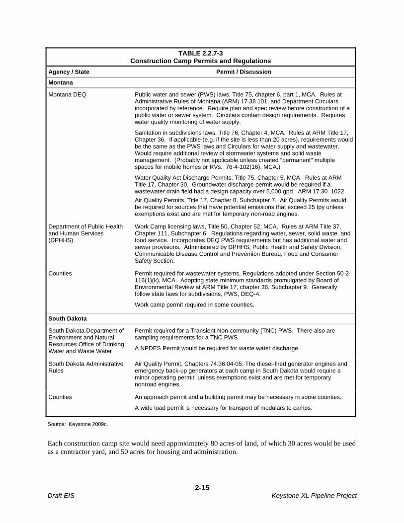
TABLE 2.2.7-3 Construction Camp Permits and Regulations
Agency / State Permit / Discussion
Montana
Montana DEQ Public water and sewer (PWS) laws, Title 75, chapter 6, part 1, MCA. Rules at Administrative Rules of Montana (ARM) 17.38 101, and Department Circulars incorporated by reference. Require plan and spec review before construction of a public water or sewer system. Circulars contain design requirements. Requires water quality monitoring of water supply.
Sanitation in subdivisions laws, Title 76, Chapter 4, MCA. Rules at ARM Title 17, Chapter 36. If applicable (e.g. if the site is less than 20 acres), requirements would be the same as the PWS laws and Circulars for water supply and wastewater. Would require additional review of stormwater systems and solid waste management. (Probably not applicable unless created "permanent" multiple spaces for mobile homes or RVs. 76-4-102(16), MCA.)
Water Quality Act Discharge Permits, Title 75, Chapter 5, MCA. Rules at ARM Title 17, Chapter 30. Groundwater discharge permit would be required if a wastewater drain field had a design capacity over 5,000 gpd. ARM 17.30. 1022.
Air Quality Permits, Title 17, Chapter 8, Subchapter 7. Air Quality Permits would be required for sources that have potential emissions that exceed 25 tpy unless exemptions exist and are met for temporary non-road engines.
Department of Public Health and Human Services (DPHHS)
Work Camp licensing laws, Title 50, Chapter 52, MCA. Rules at ARM Title 37, Chapter 111, Subchapter 6. Regulations regarding water, sewer, solid waste, and food service. Incorporates DEQ PWS requirements but has additional water and sewer provisions. Administered by DPHHS, Public Health and Safety Division, Communicable Disease Control and Prevention Bureau, Food and Consumer Safety Section.
Counties Permit required for wastewater systems, Regulations adopted under Section 50-2-116(1)(k), MCA. Adopting state minimum standards promulgated by Board of Environmental Review at ARM Title 17, chapter 36, Subchapter 9. Generally follow state laws for subdivisions, PWS, DEQ-4.
Work camp permit required in some counties.
South Dakota
South Dakota Department of Environment and Natural Resources Office of Drinking Water and Waste Water
Permit required for a Transient Non-community (TNC) PWS. There also are sampling requirements for a TNC PWS.
A NPDES Permit would be required for waste water discharge.
South Dakota Administrative Rules
Air Quality Permit, Chapters 74:36:04-05. The diesel-fired generator engines and emergency back-up generators at each camp in South Dakota would require a minor operating permit, unless exemptions exist and are met for temporary nonroad engines.
Counties An approach permit and a building permit may be necessary in some counties.
A wide load permit is necessary for transport of modulars to camps.
Source: Keystone 2009c.
Each construction camp site would need approximately 80 acres of land, of which 30 acres would be used as a contractor yard, and 50 acres for housing and administration.
2-15 Draft EIS Keystone XL Pipeline Project

Each camp would be designed to provide accommodation for approximately 600 people. The temporary housing would consist of prefabricated, modular, dormitory-style units that include heating and air conditioning systems. The camps would be comprised of sleeping areas with shared and private wash rooms, recreation facilities, telecommunications/media rooms, kitchen/dining facilities, laundry facilities, security units, and an infirmary unit.
Potable water would be provided by drilling a well where feasible. If adequate supply cannot be obtained from a well, water would be obtained from municipal sources or trucked to each camp. A wastewater treatment facility would be included in each camp. Electricity for the camps would either be generated on site through diesel-fired generators, or it would be provided by local utilities from an interconnection to their distribution system.
2.2.7.5 Access Roads
The proposed Project would use existing public and private roads to provide access to most of the construction ROW. Paved roads would not likely require improvement or maintenance prior to or during construction. However, the road infrastructure would be inspected prior to construction to ensure that the roads, bridges and cattle guards would be able to withstand oversized vehicle use during construction. Gravel roads and dirt roads may require maintenance during the construction period due to high use. Road improvements such as blading and filling would be restricted to the existing road footprint. To the extent Keystone is required to conduct maintenance of any county roads, it would be done pursuant to an agreement with the applicable county. In the event that oversized or overweight loads would be needed to transport construction materials to the Project work spreads, Keystone would submit required permit applications to the appropriate state regulatory agencies.
Construction of some temporary roads would be required in addition to upgrading of existing roads. Approximately 400 temporary access roads are needed to provide adequate access to the construction sites. Private roads and any new temporary access roads would be used and maintained only with permission of the landowner or land management agency. Some short, permanent access roads from public roads to the proposed tank farm, pump stations, delivery facilities, and intermediate MLVs would also be necessary. Approximately 50 permanent access roads would be needed.
Prior to construction, the location of new permanent access roads would be finalized. At a minimum, construction of new permanent access roads would require completion of cultural resources and biological surveys, along with the appropriate SHPO and USFWS consultations and approvals. Other state and local permits also could be required prior to construction. Maintenance of newly created access roads would be the responsibility of Keystone.
The areas of disturbance for access roads are included in the summary of lands affected, in Table 2.1.4-1. Access road temporary and permanent disturbance estimates are based on 30-foot roadway width required to accommodate oversized vehicles. All non-public roads are conservatively estimated to require upgrades and maintenance during construction.
2.3 PIPELINE SYSTEM DESIGN AND CONSTRUCTION PROCEDURES
The proposed facilities would be designed, constructed, tested, and operated in accordance with USDOT regulations 49 CFR Part 195, Transportation of Hazardous Liquids by Pipeline, and all other applicable federal and state regulations. These regulations specify pipeline material and qualification standards, minimum design requirements, and required measures to protect the pipeline from internal, external, and atmospheric corrosion. The regulations are designed to prevent crude oil pipeline accidents and to ensure adequate protection for the public.
2-16 Draft EIS Keystone XL Pipeline Project

Keystone has also prepared a draft Construction Mitigation and Reclamation (CMR) Plan (Appendix B) that details the construction methods and environmental protection measures committed to by Keystone to reduce Project construction impacts.
An additional USDOT/PHMSA/OPS requirement that would be met prior to federal government approval of pipeline construction would be the preparation a Spill Prevention, Control, and Countermeasure (SPCC) Plan to avoid or minimize the potential for harmful spills and leaks during construction of the proposed pipeline system. In addition, the preparation of an Emergency Response Plan (ERP) would also be required prior to pipeline operation. A draft version of the SPCC submitted by Keystone is included as Appendix C.
2.3.1 Pipeline Design Parameters
The pipeline would be constructed of high-strength steel pipe and mill-inspected by an authorized owner’s inspector and mill-tested to API 5L (American Petroleum Institute [API] 5L1) specification requirements. Table 2.3.1-1 outlines the selected design parameters applicable to the proposed pipe. The current design is based on grade X70 pipe, but Keystone is also evaluating the use of X80. Use of either grade pipe would meet or exceed federal standards (49 CFR 195.106). An external coating (Fusion-Bonded Epoxy, or FBE) would be applied to the pipeline and all buried facilities. Cathodic protection would be provided by impressed current to protect against external corrosion. As per 49 CFR Part 195, the pipeline would be required to have cathodic protection (CP) systems in conjunction with external coatings to mitigate against soil side corrosion. For this Project, the primary impressed current CP systems would be rectifiers coupled to semi-deep vertical anode beds at every pump station, as well as rectifiers coupled to deep-well anode beds at selected intermediate mainline valve sites. The rectifiers would be variable output transformers which would convert incoming AC power to DC voltage and current to provide the necessary current density to the CP design structures. The rectifiers would have a negative cable connection to the design structure and a positive cable connection to the anode beds. The anode beds would consist of high silicon cast iron anodes backfilled with a highly conductive coke powder to allow for an expected anode minimum life of 20 years. During operations, the CP system would be monitored and remediation performed to prolong the anode bed and systems. The semi-deep anode beds would be 12-inch diameter vertical holes spaced at 15 feet apart with a bottom hole depth of approximately 45 feet. The deep-well anode bed would be a single 12-inch diameter vertical hole with a bottom hole depth of approximately 300 feet. All pipe would be manufactured, constructed, and operated in accordance with applicable federal, state and local regulations.
TABLE 2.3.1-1 Pipe Design Parameters and Specification
Pipe Design Parameters Specification
Material code API 5L-PSL2-44th Edition
Material grade thousand pounds of pressure per square inch (ksi) (yield strength)1
Grade X70 or X80
Maximum pump station discharge 1,440 pounds per square inch gauge (psig)
Maximum operating pressure (MOP) 1,440 psig, 1,600 psig1
Minimum hydrostatic test pressure 1.25 x MOP
1 The American Petroleum Institute (API) 5L test standard is used to determine the fracture ductility of metal line pipe. Specimens are cut from sections of pipe, soaked at a prescribed temperature and tested within 10 seconds.
2-17 Draft EIS Keystone XL Pipeline Project

TABLE 2.3.1-1 Pipe Design Parameters and Specification
Pipe Design Parameters Specification
Corrosion allowance None
Minimum average joint length (feet) Nominal 80-foot (double-joint)
Field production welding processes Mechanized – gas metal; arc welding (GMAW); Manual-shielded metal arc welding (SMAW)
Pipeline design code 49 CFR Part 195
Outside diameter 36 inch
Line pipe wall thickness (0.80 design factor as per 49 CFR 195.106)
0.465 inch (X70) or 0.406 inch (X80)
Heavy wall thickness (0.72 design factor) as per 49 CFR 195.106 PHMSA special permit HCAs, highly populated areas, commercially navigable waterways as per 49 CFR Part 195.450 and station valving)
0.515 inch (X70) or 0.453 inch (X80)
Heavy wall thickness (0.72 design factor, 1,600 psig MOP as per 49 CFR 195.106) directly downstream of pump stations at lower elevations as determined by steady state and transient hydraulic analysis.
0.572 inch (X70) or 0.500 inch (X80)
Heavy wall thickness (0.60 design factor per 49 CFR 195.106 for 1,440 psig MOP; 0.67 design factor per 49 CFR 195.106 for 1,600 psig MOP); uncased road, cased railway crossings
0.618 inch (X70) or 0.543 inch (X80)
Heavy wall thickness (0.5 design factor per 49 CFR 195.106 for 1,440 psig MOP and 0.55 design factor per 49 CFR 195.106 for 1,600 psig MOP); uncased railway crossings, horizontal directional drillings (HDDs)
0.748 inch (X70) or 0.650 inch (X80)
1 The design of the proposed Project pipeline system is based on a maximum 1,440 pounds per square inch gauge (psig) discharge pressure at each pump station. The pump station discharge pressure would be a maximum of 1,440 psig. There would be situations where, due to elevation changes, the hydraulic head created would result in a MOP up to and including 1,600 psig. Suction pressure at the pump stations is generally on the order of 200 psig.
Source: Keystone 2009c, Keystone 2009f.
Additionally, Keystone filed an application with PHMSA, to design, construct and operate the proposed Project using a design factor and operating stress level of 80 percent of the steel pipe’s specified minimum yield strength (SMYS) in certain areas in lieu of the otherwise applicable 72 percent of SMYS. Keystone’s application for a special permit includes additional measures to ensure pipeline safety including over 50 conditions for the design and operation of the pipeline. PHMSA included those conditions in its approval of a similar permit in connection with the Keystone Pipeline Project, saying that those measures “provide a level of safety equal to, or greater than, that which would be provided if the pipelines were operated under existing regulations.”
2.3.2 Planned Pipeline Construction Procedures
Once engineering surveys of the ROW centerline and additional temporary workspace areas have been finalized, and the acquisition of ROW easements and any necessary acquisitions of property in fee have been completed, construction would begin.
2-18 Draft EIS Keystone XL Pipeline Project
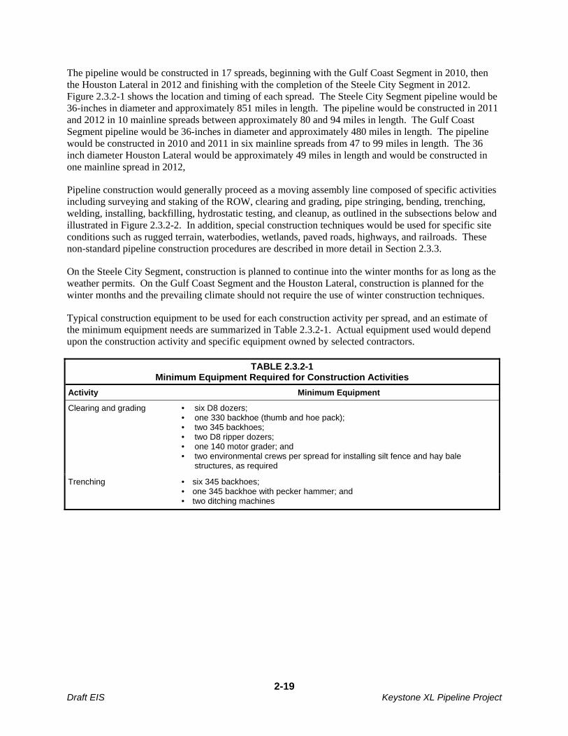
The pipeline would be constructed in 17 spreads, beginning with the Gulf Coast Segment in 2010, then the Houston Lateral in 2012 and finishing with the completion of the Steele City Segment in 2012. Figure 2.3.2-1 shows the location and timing of each spread. The Steele City Segment pipeline would be 36-inches in diameter and approximately 851 miles in length. The pipeline would be constructed in 2011 and 2012 in 10 mainline spreads between approximately 80 and 94 miles in length. The Gulf Coast Segment pipeline would be 36-inches in diameter and approximately 480 miles in length. The pipeline would be constructed in 2010 and 2011 in six mainline spreads from 47 to 99 miles in length. The 36 inch diameter Houston Lateral would be approximately 49 miles in length and would be constructed in one mainline spread in 2012,
Pipeline construction would generally proceed as a moving assembly line composed of specific activities including surveying and staking of the ROW, clearing and grading, pipe stringing, bending, trenching, welding, installing, backfilling, hydrostatic testing, and cleanup, as outlined in the subsections below and illustrated in Figure 2.3.2-2. In addition, special construction techniques would be used for specific site conditions such as rugged terrain, waterbodies, wetlands, paved roads, highways, and railroads. These non-standard pipeline construction procedures are described in more detail in Section 2.3.3.
On the Steele City Segment, construction is planned to continue into the winter months for as long as the weather permits. On the Gulf Coast Segment and the Houston Lateral, construction is planned for the winter months and the prevailing climate should not require the use of winter construction techniques.
Typical construction equipment to be used for each construction activity per spread, and an estimate of the minimum equipment needs are summarized in Table 2.3.2-1. Actual equipment used would depend upon the construction activity and specific equipment owned by selected contractors.
TABLE 2.3.2-1 Minimum Equipment Required for Construction Activities
Activity Minimum Equipment
Clearing and grading • six D8 dozers; • one 330 backhoe (thumb and hoe pack); • two 345 backhoes; • two D8 ripper dozers; • one 140 motor grader; and • two environmental crews per spread for installing silt fence and hay bale structures, as required
Trenching • six 345 backhoes; • one 345 backhoe with pecker hammer; and • two ditching machines
2-19 Draft EIS Keystone XL Pipeline Project
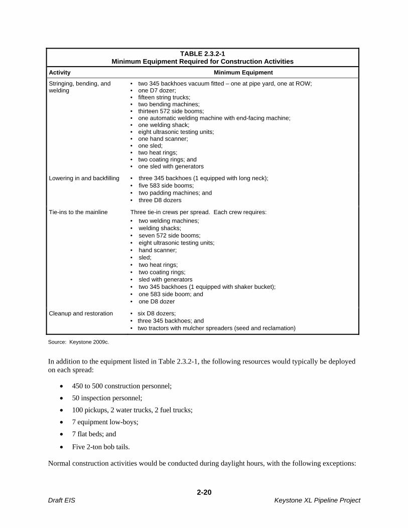
TABLE 2.3.2-1 Minimum Equipment Required for Construction Activities
Activity Minimum Equipment
Stringing, bending, and welding
• two 345 backhoes vacuum fitted – one at pipe yard, one at ROW; • one D7 dozer; • fifteen string trucks; • two bending machines; • thirteen 572 side booms; • one automatic welding machine with end-facing machine; • one welding shack; • eight ultrasonic testing units; • one hand scanner; • one sled; • two heat rings; • two coating rings; and • one sled with generators
Lowering in and backfilling • three 345 backhoes (1 equipped with long neck); • five 583 side booms; • two padding machines; and • three D8 dozers
Tie-ins to the mainline Three tie-in crews per spread. Each crew requires:
• two welding machines; • welding shacks; • seven 572 side booms; • eight ultrasonic testing units; • hand scanner; • sled; • two heat rings; • two coating rings; • sled with generators • two 345 backhoes (1 equipped with shaker bucket); • one 583 side boom; and • one D8 dozer
Cleanup and restoration • six D8 dozers; • three 345 backhoes; and • two tractors with mulcher spreaders (seed and reclamation)
Source: Keystone 2009c.
In addition to the equipment listed in Table 2.3.2-1, the following resources would typically be deployed on each spread:
450 to 500 construction personnel;
50 inspection personnel;
100 pickups, 2 water trucks, 2 fuel trucks;
7 equipment low-boys;
7 flat beds; and
Five 2-ton bob tails.
Normal construction activities would be conducted during daylight hours, with the following exceptions:
2-20 Draft EIS Keystone XL Pipeline Project
Completion of critical tie-ins on the ROW would likely occur after daylight hours. Completion requires tie-in welds, non-destructive testing and sufficient backfill to stabilize the ditch.
HDD operations may be conducted after daylight hours, if determined by the contractor to be necessary to complete a certain location. In some cases, that work may be required continuously until the work is completed; this may last one or more 24-hour days. Such operations may include drilling and pull-back operation, depending upon the site and weather conditions, permit requirements, schedule, crew availability, and other factors.
While not anticipated in typical operations, certain work may be required after the end of daylight hours due to weather conditions, for safety, or for other Project requirements.
2.3.2.1 Surveying and Staking
Before construction begins, the construction ROW boundaries and any additional temporary workspace areas would be marked. This would outline the limits of the approved work area. The location of approved access roads and existing utility lines would be flagged. Landowner fences would be braced and cut, and if livestock is present, temporary gates and fences would be installed. Wetland boundaries and other environmentally sensitive areas would be marked or fenced for protection. A survey crew would stake the centerline of the proposed trench and any buried utilities along the ROW.
2.3.2.2 Clearing and Grading
Prior to vegetation removal along slopes leading to wetlands and riparian areas, temporary erosion control measures such as silt fences or straw bales would be installed. The work area would be cleared of vegetation including crops and obstacles such as trees, logs, brush, or rocks.
Grading would be performed where necessary to provide a reasonably level work surface. Where the ground is relatively flat and does not require grading, rootstock would be left in the ground. More extensive grading would be required in steep slope areas to prevent excessive bending of the pipe.
2.3.2.3 Trenching
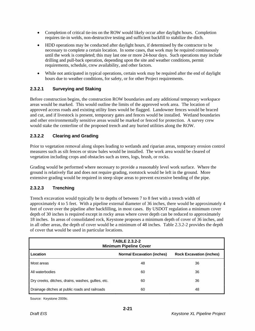
Trench excavation would typically be to depths of between 7 to 8 feet with a trench width of approximately 4 to 5 feet. With a pipeline external diameter of 36 inches, there would be approximately 4 feet of cover over the pipeline after backfilling, in most cases. By USDOT regulation a minimum cover depth of 30 inches is required except in rocky areas where cover depth can be reduced to approximately 18 inches. In areas of consolidated rock, Keystone proposes a minimum depth of cover of 36 inches, and in all other areas, the depth of cover would be a minimum of 48 inches. Table 2.3.2-2 provides the depth of cover that would be used in particular locations.
TABLE 2.3.2-2 Minimum Pipeline Cover
Location Normal Excavation (inches) Rock Excavation (inches)
Most areas 48 36
All waterbodies 60 36
Dry creeks, ditches, drains, washes, gullies, etc. 60 36
Drainage ditches at public roads and railroads 60 48
Source: Keystone 2009c.
2-21 Draft EIS Keystone XL Pipeline Project
Trenching may be carried out before or after bending and welding, depending upon several factors including soil characteristics, water table, presence of drain tiles, and weather conditions at the time of construction.
In areas of rocky soils or bedrock, tractor-mounted mechanical rippers or rock trenchers would fracture the rock prior to excavation. Blasting with explosives would be required where mechanical equipment cannot break up or loosen the bedrock. The bottom of the trench would then be padded with borrow material such as sand or gravel, and excavated rock would be used to backfill the trench to the top of the existing bedrock profile. Blasting is described in more detail in Section 2.3.3.8.
The actual depth of topsoil would be removed from the trench up to a maximum depth of 12 inches and segregated. Topsoil would be separated from subsoil in three different methods:
Trench area topsoil separation – When soil is removed from only the trench, topsoil would be piled on the near-side of the trench and subsoil on the far side of the trench. This separation would allow for proper restoration of the soil during the backfilling process.
Trench and spoil side topsoil separation – When soil is removed from both the trench and the spoil side, topsoil would be stored on the near-side of the construction ROW edge, and the subsoil on the spoil-side of the trench.
ROW grading topsoil separation – ROW grading may occur to provide a level working surface, where it is beneficial from a construction standpoint, or where required by landowners or land managers. Where grading occurs and there is a need to separate topsoil from subsoil, topsoil would be removed from the entire area to be graded and stored separately from the subsoil.
These arrangements for separating topsoil reduce the potential for mixing of subsoil and topsoil. In addition, the spoil piles would be spaced to accommodate storm water runoff. Figures 2.1.4-1 to 2.1.4-3 illustrate these options.
On agricultural land, rocks that are exposed on the surface due to construction activity would be removed from the ROW prior to and after topsoil replacement. Rock removal would also occur in rangeland to ensure that the productive capability of the land is maintained. In some landscapes, thin soils overlay bedrock, or exposed bedrock exists at the surface. In these cases, rock would be replaced to the extent practicable. Clearing of rocks could be carried out either manually or with a mechanical rock picker and topsoil would be preserved. Rocks that are similar in size to those occurring in the undisturbed landscape would be left in place to the extent practicable. Rock removed from the ROW would be either hauled away for disposal in appropriate facilities or placed in a location acceptable to the landowner.
2.3.2.4 Pipe Stringing, Bending, and Welding
Pipe stringing, bending, and welding would be done either prior to, or following trenching. Sections of externally coated pipe approximately 80 feet long (also referred to as “joints”) would be transported by truck to the ROW and placed along the ROW. Individual sections of the pipe would then be bent to conform to the contours of the trench using a track-mounted, hydraulic pipe-bending machine. For larger bend angles, fabricated bends may be used.
After the pipe sections are bent, the pipeline joints would be lined up and held in position until welding. The joints would be welded together into long strings and placed on temporary supports. All welds would be inspected using non-destructive radiographic, ultrasonic, or other USDOT approved methods. Welds that do not meet established specifications would be repaired or removed and replaced. Once the welds are approved, a protective epoxy coating would be applied to the welded joints to inhibit corrosion.
2-22 Draft EIS Keystone XL Pipeline Project
The pipeline would then be electronically inspected or “jeeped” for faults or holidays (holes) in the epoxy coating and visually inspected for any faults, scratches, or other coating defects. Damage to the coating would be repaired before the pipeline is lowered into the trench.
In rangeland areas used for grazing, construction activities can hinder the movement of livestock if the animals cannot be temporarily relocated by the owner. Construction activities may also hinder the movement of wildlife. To reduce impacts to livestock and wildlife movements during construction, Keystone would leave hard plugs (short lengths of unexcavated trench) or install soft plugs (areas where the trench is excavated and replaced with minimal compaction) to allow livestock and wildlife to cross the trench safely. Soft plugs would be constructed with a ramp on each side to facilitate egress from the trench for animals that may fall into the trench. Generally the work carried out on each construction spread would be synchronized with the welding activities to minimize the amount of open trench, to the extent possible.
2.3.2.5 Installing and Backfilling
Prior to installing the pipe into the trench, the trench would be cleared of rocks and debris that might damage the pipe or the pipe coating. If water has entered the trench, dewatering may be required prior to installation. Discharge of water from dewatering would be accomplished in accordance with applicable discharge permits. On sloped terrain, trench breakers (e.g., stacked sand bags or foam) would be installed in the trench at specified intervals to prevent subsurface water movement along the pipeline.
Where rock occurs within the trench perimeter, abrasion resistant coatings or rock shields would be used to protect the pipe prior to installation. In some cases sand or gravel padding material may be used to protect the pipeline from damage during installation. In no case would topsoil be used as a padding material. The pipeline would then be lowered into the trench and the trench would be backfilled using the excavated material. Topsoil would be returned to its original position after subsoil is backfilled in the trench.
2.3.2.6 Hydrostatic Testing
The pipeline would be hydrostatically tested in sections of approximately 30 to 50 miles. Hydrostatic testing provides assurance that the system is capable of withstanding the maximum operating pressure. The hydrostatic test would be conducted in accordance with 49 CFR Part 195. The process is as follows:
Isolate the pipe segment with test manifolds;
Fill the segment with water;
Pressurize the segment to a minimum of 1.25 times the maximum operating pressure (MOP) at the high point elevation of each test section; and
Maintain that pressure for a period of eight hours.
Fabricated assemblies could be tested prior to installation in the trench for a period of four hours.
The pipeline would be hydrostatically tested after backfilling and all construction work that would directly affect the pipe is complete. If leaks are found, they would be repaired and the section of pipe retested until specifications are met.
Water for hydrostatic testing would be obtained from rivers and streams crossed by the pipeline and in accordance with federal, state, and local regulations. This water would then be transferred to another pipe
2-23 Draft EIS Keystone XL Pipeline Project

segment for subsequent hydrostatic testing. Alternately, the water would be discharged after it is tested to ensure compliance with the NPDES discharge permit requirements and treated if necessary.
Hydrostatic test water would be discharged either to the source waterbody after testing to ensure that discharge water meets the requirements of the applicable NPDES discharge permit, or it would be discharged to a suitable upland area within the same water basin as the source waterbody. To reduce the velocity of the discharge to upland areas, energy dissipating devices would be employed. Energy dissipation devices that are consistent with Best Management Practices (BMP) protocols include:
Splash Pup – A splash pup consists of a piece of large diameter pipe (usually over 20-inch outside diameter) of variable length with both ends partially blocked that is welded perpendicularly to the discharge pipe. As the discharge hits against the inside wall of the pup, the velocity is rapidly reduced and the water is allowed to flow out either end. A variation of the splash pup concept, commonly called a diffuser, incorporates the same design, but with capped ends and numerous holes punched in the pup to diffuse the energy.
Splash Plate – The splash plate is a quarter section of 36-inch pipe welded to a flat plate and attached to the end of a 6-inch discharge pipe. The velocity is reduced by directing the discharge stream into the air as it exits the pipe. This device is also effective for most overland discharge.
Plastic Liner – In areas where highly erodible soils exist or in any low flow drainage channel, it is a common practice to use layers of visqueen (or any of the new construction fabrics currently available) to line the receiving channel for a short distance. One anchoring method may consist of a small load of rocks to keep the fabric in place during the discharge. Additional methods, such as the use of plastic sheeting or other material to prevent scour would be used as necessary to prevent excessive sedimentation during dewatering.
Straw Bale Dewatering Structure – Straw bale dewatering structures are designed to dissipate and remove sediment from the water being discharged. Straw bale structures could be used for on land discharge of wash water and hydrostatic test water and in combination with other energy dissipating devices for high volume discharges. A dewatering filter bags may be used as an alternative to straw bale dewatering structures.
Hydrostatic test water would not be discharged into state-designated exceptional value waters, waterbodies which provide habitat for federally-listed threatened or endangered species, or waterbodies designated as public water supplies, unless appropriate federal, state, and local permitting agencies grant written permission. To avoid impacts from introduced species, no inter-basin transfers (discharge) of hydrostatic test water would occur. Water would be disposed of using good engineering judgment so that all federal, state, and local environmental standards are met. Dewatering lines would be of sufficient strength and would be securely supported and tied down at the discharge end to prevent whipping during discharge.
2.3.2.7 Pipe Geometry Inspection, Final Tie-ins, and Commissioning
Prior to final tie-ins, the pipeline would be inspected using an electronic caliper (geometry) pig to ensure the pipeline does not have any dents or other deformations that might hinder effective operation of the pipeline. Following successful hydrostatic testing, test manifolds would be removed and the final pipeline tie-ins would be welded and inspected.
After the final tie-ins are complete and inspected, the pipeline would be cleaned and dewatered and the pipeline would be commissioned through the verification of proper installation and functionality of the pipeline and appurtenant systems, including control and communication equipment.
2-24 Draft EIS Keystone XL Pipeline Project
2.3.2.8 Cleanup and Restoration
Cleanup would include the removal of construction debris, final contouring, and the installation of erosion control features. The cleanup process would begin after backfilling as soon as possible given weather conditions. Final cleanup would be completed in approximately 20 days after the completion of backfilling assuming appropriate weather conditions prevail. Removed construction debris would be disposed in appropriate disposal facilities.
Reseeding of the ROW would occur as soon as possible after completion of cleanup, thus stabilizing soil profiles rapidly. Work would also include revegetation and restoration of native vegetation where appropriate. Procedures would depend on weather and soil conditions and would follow recommended rates and seed mixes provided by the landowner, the land management agency, or the Natural Resources Conservation Service (NRCS).
Access to the permanent easement would be restricted using gates, boulders, or other barriers to minimize unauthorized access by all-terrain vehicles, if requested by the landowner. Also, pipeline markers would be provided for identification of the pipeline location for safety purposes, in accordance with the requirements of the DOT Regulations at 49 CFR Section 195.410 (Line Markers), which would be maintained during pipeline operation, including the following:
Pipeline markers would be installed on both sides of all highways, roads, road ROWs, railroads and waterbody crossings;
Pipeline markers would be made from industrial strength materials to withstand abrasion from wind and damage from cattle;
Pipeline markers would be installed at all fences;
Pipeline markers would be installed along the ROW to provide line-of-sight marking of the pipeline, providing it is practical to do so and consistent with the type of land use, such that it does not hinder the use of the property by the landowner. Pipeline markers would be installed at all angle points, and at intermediate points, where practical, so that from any marker, the adjacent marker in either direction would be visible;
Consideration would be given to installing additional markers, except where they would interfere with land use (i.e., farming);
Aerial markers showing identifying numbers would be installed at each station, mainline valve, and mainline check valve site; and
Signs would be installed and maintained on the perimeter fence at each mainline valve and pump stations where the pipeline enters and exits the fenced area.
Markers would identify the owner of the pipeline and convey emergency contact information. Special markers providing information and guidance to aerial patrol pilots also would be installed.
2.3.2.9 Post-Construction Reclamation Monitoring and Response
Reclamation on the ROW would be inspected after the first growing season to determine the success of revegetation and noxious weed control. Erosion would be repaired and areas that were unsuccessfully re-established would be revegetated by Keystone or by compensation of the landowner to reseed as necessary. For further information on re-vegetation and weed control, please refer to the CMR Plan, attached as Appendix B. Landowners would be informed of all work anticipated during monitoring.
2-25 Draft EIS Keystone XL Pipeline Project
2.3.3 Special Construction Procedures
Special construction techniques would be used when crossing roads, highways and railroads; steep terrain; unstable soils; waterbodies; wetlands; areas that require blasting; and residential and commercial areas. These special techniques are described below.
2.3.3.1 Road, Highway, and Railroad Crossings
Construction across paved roads, highways, and railroads would be in accordance with the requirements of the appropriate road and railroad crossing permits and approvals. In general, all major paved roads, all primary gravel roads, highways, and railroads would be crossed by boring beneath the road or railroad, as shown in Figure 2.3.3-1. Boring would result in minimal or no disruption to traffic at road or railroad crossings. Each boring would take one to two days for most roads and railroads, and 10 days for long crossings such as interstate or four-lane highways.
Initially, a pit would be excavated on each side of the feature, then boring equipment would be placed into the pit and a hole would be bored under the road at least equal to the diameter of the pipe. Then, a prefabricated pipe section would be pulled through the borehole. For long crossings, sections would be welded onto the pipe string just before being pulled through the borehole.
If permitted by local regulators and landowners, smaller gravel roads and driveways would likely be crossed using an open-cut method that would typically take between one and two days to complete. This would require temporary road closures and the establishment of detours for traffic. If no reasonable detour is feasible, at least one lane of traffic would be kept open in most cases. Keystone would post signs at these open-cut crossings and would develop traffic control plans to reduce traffic disturbance and protect public safety.
2.3.3.2 Pipeline, Utility, and Other Buried Feature Crossings
Keystone and its pipeline contractors would comply with DOT regulations, utility agreements, and industry BMPs with respect to utility crossing and separation specifications. One-call notification would be made for all utility crossings so respective utilities would be identified accordingly. Similarly, private landowners would be notified of forthcoming construction activities so that buried features such as stock watering systems could be avoided or replaced. Prior to construction, each rancher with a stock watering system would be asked to provide the location of any waterlines in the construction area. The location of these waterlines would be documented and some waterlines would be lowered prior to construction. In the case of existing buried oil or gas pipelines, the owner of the facility would be asked to provide the locations of any pipes in the construction area. Metallic pipelines would be located by a line locating crew prior to construction.
Unless otherwise specified in a crossing agreement, the contractor would excavate to allow installation of the pipeline across the existing pipeline or utility with a minimum clearance of 12 inches. The clearance would be filled with sandbags or suitable fill material to maintain the clearance. Backfill of the crossing would be compacted in lifts to ensure continuous support of the existing utility.
For some crossings, the owner of the utility or buried feature may require the facility to be excavated and exposed by their own employees prior to the Keystone contractor getting to the location. In those cases, Keystone would work with owners to complete work to the satisfaction of the owner.
Where the owner of the utility does not require pre-excavation, generally, the pipeline contractor would locate and expose the utility before conducting machine excavation.
2-26 Draft EIS Keystone XL Pipeline Project
2.3.3.3 Steep Terrain
Where the proposed pipeline route would traverse steep slopes, they would be graded to reduce slope angles, thus allowing safer operation of construction equipment and reducing the degree of required pipe bending. In areas where the pipeline route crosses side slopes, cut and fill grading would potentially be employed to obtain a safe working terrace. Prior to cut and fill grading on steep terrain, topsoil would be stripped from the ROW and stockpiled. If feasible given soil and slope conditions, soil from the high side of the ROW would be excavated and moved to the low side, thus creating a safer and more level working surface. After the pipeline installation, soil from the low side of the ROW would be returned to the high side and the contour of the slope would be restored to its pre-construction condition to the degree practicable.
Temporary sediment barriers such as silt fences and straw bales would be installed where appropriate to prevent erosion and siltation of wetlands, waterbodies, or other environmentally sensitive areas. During grading, temporary slope breakers consisting of mounded and compacted soil would be installed across the ROW. In the proposed Project cleanup phase, permanent slope breakers would be installed where appropriate. For additional detail on sediment barriers and slope breakers, refer to Section 4.5 of the CMR Plan (Appendix B).
Seed would then be applied to steep slopes and the ROW would be mulched with hay or non-brittle straw, or protected with erosion control geofabrics. Where appropriate to avoid animal entanglement, geofabric mesh size would be 2-inches or greater. Sediment barriers would be maintained across the ROW until permanent vegetation is established. Additional temporary workspaces may be required for storage of graded material and/or topsoil during construction.
2.3.3.4 Unstable Soils
Special construction techniques and environmental protection measures would be applied to areas with unstable soils, such as those within the Sand Hills region of South Dakota and Nebraska, and to areas with high potential for landslides, erosion, and mass wasting. Construction in these areas could require extended temporary workspace areas.
Topsoil piles would be protected from erosion through matting, mulching, watering or tackifying to the extent practicable. Photodegradable matting would be applied on steep slopes or areas prone to extreme wind exposure such as north- or west-facing slopes and ridge tops. Biodegradable pins would be used in place of metal staples to hold the matting in place.
Re-seeding would be carried out using native seed mixes certified noxious weed-free if possible. Land imprinting may be employed to create impressions in the soil, thereby reducing erosion, improving moisture retention and creating micro-sites for seed germination. Keystone would work with landowners to evaluate fencing the ROW from livestock, or alternatively, to provide compensation if a pasture needs to be rested until vegetation can become established.
2.3.3.5 Perennial Waterbody Crossings
A total of 341 perennial waterbodies would be crossed during the construction of the proposed Project. One of four techniques would be used to cross perennial waterbodies: the open-cut wet method, the dry flume method, the dry dam-and-pump method, or, HDD, as described below. For each perennial waterbody crossing, a site specific engineering and geomorphologic analysis would determine the best method to use to avoid and reduce aquatic impacts. The actual crossing method employed at an individual perennial stream would depend on permit conditions from USACE and other relevant
2-27 Draft EIS Keystone XL Pipeline Project
regulatory agencies, as well as additional conditions that may be imposed by landowners or land managers at the crossing location. See Appendices D and E for Site Specific Waterbody Crossing Plans and Waterbody Crossing Tables.
Open-Cut Crossing Method
Keystone’s preferred crossing method would be the open-cut crossing method. This method would involve trenching through the waterbody while water continues to flow through the construction work area. Backhoes operating from one or both banks would excavate the trench within the streambed. In wider rivers, in-stream operation of equipment could be necessary. Trench spoil excavated from the streambed generally would be placed at least 10 feet away from the water’s edge unless stream width exceeds the reach of the excavation equipment. Sediment barriers would be installed where necessary to prevent excavated spoil from entering the water. Hard or soft trench plugs would be placed to prevent the flow of water into the upland portions of the trench. Before construction, temporary bridges (e.g., subsoil fill over culverts, timber mats supported by flumes, railcar flatbeds, flexi-float apparatus) would be installed across all perennial waterbodies to allow construction equipment to cross with reduced disturbance. Clearing crews would be allowed one pass through the waterbodies prior to temporary bridge construction. All other construction equipment would be required to use the bridges.
Pipe segments for the crossing would be welded and positioned adjacent to the waterbody. When crossing saturated wetlands with flowing waterbodies using the open-cut method, the pipe coating would be covered with reinforced concrete or concrete weights to provide negative buoyancy. The need for negative buoyancy would be determined by detailed design and site considerations at the time of construction.
After the trench is excavated, the pipeline segment would be carried, pushed, or pulled across the waterbody and positioned in the trench. The trench would then be backfilled with native material or with imported material if required by applicable permits. Following backfilling, the banks would be restored and stabilized.
Dry Flume Method
The proposed Project would utilize the dry flume method where technically feasible on selected environmentally sensitive waterbodies. The dry flume crossing method involves diverting the flow of water across the trenching area through one or more flume pipes placed in the waterbody. Trenching, pipe installation, and backfilling would be done while water flow is maintained for all but a short reach of the waterbody at the actual crossing location. Once backfilling is completed, the stream banks would be restored and stabilized and the flume pipes would be removed.
Dry Dam-and-Pump Method
The proposed Project would potentially use the dry dam-and-pump method where practical on selected environmentally sensitive waterbodies. The dam-and-pump method is similar to the dry flume method except that pumps and hoses would be used instead of flumes to move water around the construction work area. As with the dry flume method, trenching, pipe installation, and backfilling would be done while water flow is maintained for all but a short reach of the waterbody at the actual crossing location. Once backfilling is completed, the stream banks would be restored and stabilized and the pump hoses would be removed.
2-28 Draft EIS Keystone XL Pipeline Project

Horizontal Directional Drilling Method
The HDD method of construction would be used at 38 waterbody crossings for the proposed Project, as shown in Table 2.3.3-1. The HDD method could also be used to bore beneath terrestrial areas that contain special resources that require avoidance.
Waterbodies Keystone has considered for HDD include commercially navigable waterbodies, waterbodies wider than 100 feet, waterbodies with terrain features that prohibit open crossing methods, waterbodies adjacent to features such as roads and railroads, and sensitive environmental resource areas. Additional HDD crossings could be planned as a result of resource agency, landowner, or land manager concerns. The HDD method involves drilling a pilot hole under the waterbody and banks, then enlarging the hole through successive ream borings with progressively larger bits until the hole is large enough to accommodate a pre-welded segment of pipe. Throughout the process of drilling and enlarging the hole, a water-bentonite slurry would be circulated to power and lubricate the drilling tools, remove drill cuttings, and provide stability to the drilled holes. Pipe sections long enough to span the entire crossing would be staged and welded along the construction work area on the opposite side of the waterbody and then pulled through the drilled hole. Depending on the angle of approach of the pipeline alignment to the water crossing, a “false ROW” could be needed to be cleared on the drill rig side of the crossing to allow drill rig placement at the appropriate angle to the waterbody. Ideally, use of the HDD method results in reduced impact to the banks, bed, and/or water quality of the waterbody being crossed. Keystone has created Site Specific Waterbody Crossing Plans (Appendix D) that detail procedures at each HDD water crossing to reduce potential risks.
TABLE 2.3.3-1 Waterbodies Crossed Using the Horizontal Directional Drill Method
Waterbody Number of Crossings Approximate Milepost(s)
Steele City Segment
Milk River 1 82.7
Missouri River 1 89.0
Yellowstone River 1 196.0
Little Missouri River 1 292.1
Cheyenne River 1 425.9
White River 1 536.9
Keya Paha River 1 599.8
Niobrara River 1 615.3
Cedar River 1 696.5
Loup River 1 739.8
Platte River 1 755.4
Gulf Coast Segment
Deep Fork 1 22.1
North Canadian River 1 38.7
Little River 1 70.5
Canadian River 1 74.2
Clear Boggy Creek 1 126.7
2-29 Draft EIS Keystone XL Pipeline Project

TABLE 2.3.3-1 Waterbodies Crossed Using the Horizontal Directional Drill Method
Waterbody Number of Crossings Approximate Milepost(s)
Red River 1 155.3
Bois D’Arc Creek 1 1.6
North Sulphur River 1 190.2
South Sulphur River 1 201.2
White Oak Creek 1 212.3
Big Cyprus Creek 1 227.6
Small Lake 1 254.1
Big Sandy Creek 1 256.1
Sabine River 1 262.7
East Fork of Angelina River 1 312.3
Angelina River 1 333.3
Neches River 1 367.3
Menard Creek 1 413.8
Neches Valley Canal Authority 1 459.7
Lower Neches Valley Canal Authority 1 459.9
Willow Marsh Bayou 1 457.0
Hillebrandt Bayou 1 470.9
Port Arthur Canal and Entergy Corridor 1 478.2
Houston Lateral
Trinity Creek Marsh 1 17.7
Trinity River 1 22.8
Cedar Bayou 1 35.6
San Jacinto River 1 43.3
Source: Keystone 2009c.
2.3.3.6 Intermittent Waterbody Crossings
Approximately 621 intermittent waterbodies would be crossed by the proposed Project (Appendix E). In the event that these intermittent waterbodies are dry or stagnant at the time of crossing, conventional upland cross-country construction techniques would be used. The pipeline would be installed with the open-cut wet crossing method if water is flowing at the time of installation. The specific method used for each crossing would be based on site-specific analyses of conditions at the time of installation so that the method selected would result in lower levels of environmental impact.
Required additional temporary workspace areas would be located at least 10 feet away from the water’s edge, except where the adjacent upland consists of actively cultivated or rotated cropland or other disturbed land. This distance is what a standard backhoe can reach and would prevent the need for additional equipment to relay the soil a further distance from the trench. For construction access,
2-30 Draft EIS Keystone XL Pipeline Project
temporary bridges, including subsoil fill over culverts, timber mats supported by flumes, railcar flatbeds, and flexi-float apparatus would be installed across waterbodies. Clearing crews would be allowed one pass through the waterbodies prior to temporary bridge construction. All other construction equipment would be required to use the bridges.
To minimize the potential for sediment runoff during clearing, sediment barriers such as silt fence and staked straw bales would be installed and maintained on drainages across the ROW adjacent to waterbodies and within additional temporary workspace areas. Silt fences and straw bales located across the working side of the ROW would be removed during the day when vehicle traffic is present and would be replaced each night. Drivable berms would potentially be installed across the ROW instead of silt fences or straw bales.
After pipeline installation, stream banks would be restored to preconstruction contours or to a stable configuration. Stream banks would be seeded with native grasses for stabilization, and mulched or covered with erosion control fabric. Where willows or other shrubs are found at the crossing site, revegetation efforts could include planting of willow sprigs or other methods to establish a stable stream bank. Steep bank erosion control measures would be installed as necessary in accordance with permit requirements, including rock riprap, gabion baskets (rock enclosed in wire bins), log walls, vegetated geogrids, willow cuttings, or alternative wood-based structures where required by regulatory authorities. Banks would be temporarily stabilized within 24 hours of completing in-stream construction. Sediment barriers, such as silt fences, straw bales or drivable berms, would be maintained across the ROW at all stream or other waterbody approaches until permanent vegetation becomes established. Temporary equipment bridges would be removed following construction.
Equipment refueling and lubricating at waterbodies would take place in upland areas 100 feet or more from the water. In the event that equipment refueling and lubricating becomes necessary within 100 feet of a wetland or waterbody, the SPCC Plan would be adhered to relative to the handling of fuel and other hazardous materials.
2.3.3.7 Wetland Crossings
Pipeline construction across wetlands would be similar to typical conventional upland cross-country construction procedures, with modifications to reduce the potential for affects to wetland hydrology and soil structure. The wetland crossing methods used would depend largely on the stability of the soils at the location at time of construction. In some areas where wetlands overlie rocky soil, the pipe would be padded with rock-free soil or sand before backfilling with native bedrock and soil.
Clearing of vegetation in wetlands would be limited to flush-cutting of trees and shrubs and their subsequent removal from wetland areas. Stump removal, grading, topsoil segregation, and excavation would be limited to the area immediately over the trench line. During clearing, sediment barriers, such as silt fences and staked straw bales, would be installed and maintained on slopes adjacent to saturated wetlands and within additional temporary workspace areas as necessary to reduce sediment runoff. Tall growing vegetation would be allowed to regrow in riparian areas in the temporary ROW, but not in the permanent ROW.
For unsaturated soils able to support construction equipment without equipment mats, construction would occur in a manner similar to conventional upland cross-country construction techniques. Topsoil would be segregated over the trench line.
2-31 Draft EIS Keystone XL Pipeline Project
Push-Pull Technique
Where wetland soils are saturated or inundated, the pipeline could be installed using the push-pull technique. The push-pull installation process would involve stringing and welding the pipeline outside of the wetland. Excavating and backfilling the trench would be done using a backhoe supported by equipment mats or timber riprap. Trench breakers would be installed where necessary to prevent the subsurface drainage of water from wetlands. The pipeline segment would be installed in the wetland by equipping it with floats and pushing or pulling it across the water-filled trench. After the pipeline is floated into place, the floats would be removed and the pipeline would sink into place. Most pipes installed in saturated wetlands would be coated with concrete or installed with set-on weights to provide negative buoyancy. Where topsoil has been segregated from subsoil, the subsoil would be backfilled first followed by the topsoil. Restoration of contours would be accomplished during backfilling because little or no grading would occur in wetlands.
Construction equipment working in saturated wetlands would be limited to that area essential for clearing the ROW, excavating the trench, welding and installing the pipeline, backfilling the trench, and restoring the ROW. In areas where there is no reasonable access to the ROW except through wetlands, non-essential equipment would be allowed to travel through wetlands only if the ground is firm enough or has been stabilized to avoid rutting. Additional temporary workspace areas would be required on both sides of particularly wide saturated wetlands to stage construction, weld the pipeline, and store materials. These additional temporary workspace areas would be located in upland areas a minimum of 10 feet from the wetland edge. This distance is what a standard backhoe can reach and would prevent the need for additional equipment to make multiple trips to and from the wetland to ferry the soil a further distance away.
Equipment mats, timber riprap, gravel fill, geotextile fabric, and straw mats would be removed from wetlands following backfilling except in the travel lane to allow continued, but controlled, access through the wetland until the completion of construction. Upon the completion of construction, these materials would be removed. Topsoil would be replaced to the original ground level leaving no crown over the trench line and any excess spoil would be removed from the wetland.
Where wetlands are located at the base of slopes, permanent slope breakers would be constructed across the ROW in upland areas adjacent to the wetland boundary. Temporary sediment barriers would be installed where necessary until revegetation of adjacent upland areas is successful. Once revegetation is successful, sediment barriers would be removed from the ROW and disposed of properly. Final locations requiring weighted pipe for negative buoyancy would be determined by detailed design and site conditions at the time of construction.
2.3.3.8 Blasting and Ripping
Blasting could be required where the bedrock type within 84 inches (7 feet) of the surface is lithic or very strongly cemented rock. Blasting would involve the use of explosives to break up the hard rock. Blasting could be required in areas where consolidated shallow bedrock or boulders cannot be removed by conventional excavation methods and could be needed to clear the ROW and to fracture rock within the ditch. In areas where the bedrock type within 84 inches (7 feet) of the surface is expected to be dense or highly stratified, ripping could be required. Ripping would involve tearing up the rock with mechanical excavators. Table 2.3.3-2 shows the location of areas where blasting could be required.
2-32 Draft EIS Keystone XL Pipeline Project
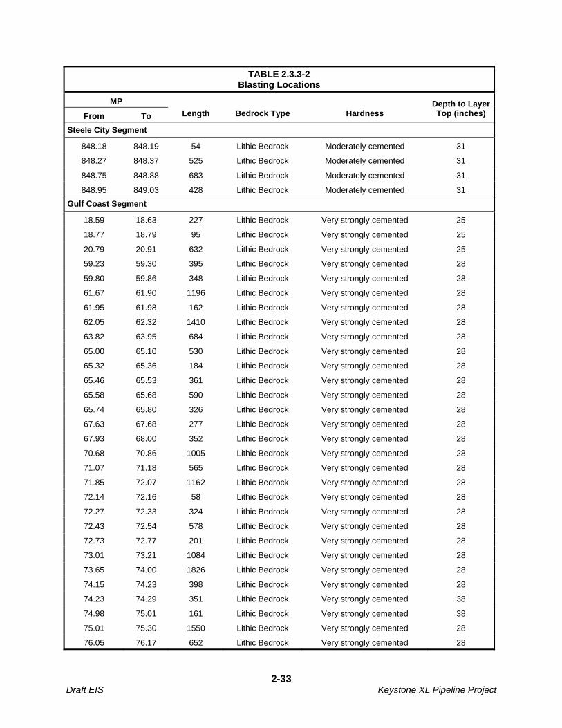
TABLE 2.3.3-2 Blasting Locations
MP
From To Length Bedrock Type Hardness Depth to Layer Top (inches)
Steele City Segment
848.18 848.19 54 Lithic Bedrock Moderately cemented 31
848.27 848.37 525 Lithic Bedrock Moderately cemented 31
848.75 848.88 683 Lithic Bedrock Moderately cemented 31
848.95 849.03 428 Lithic Bedrock Moderately cemented 31
Gulf Coast Segment
18.59 18.63 227 Lithic Bedrock Very strongly cemented 25
18.77 18.79 95 Lithic Bedrock Very strongly cemented 25
20.79 20.91 632 Lithic Bedrock Very strongly cemented 25
59.23 59.30 395 Lithic Bedrock Very strongly cemented 28
59.80 59.86 348 Lithic Bedrock Very strongly cemented 28
61.67 61.90 1196 Lithic Bedrock Very strongly cemented 28
61.95 61.98 162 Lithic Bedrock Very strongly cemented 28
62.05 62.32 1410 Lithic Bedrock Very strongly cemented 28
63.82 63.95 684 Lithic Bedrock Very strongly cemented 28
65.00 65.10 530 Lithic Bedrock Very strongly cemented 28
65.32 65.36 184 Lithic Bedrock Very strongly cemented 28
65.46 65.53 361 Lithic Bedrock Very strongly cemented 28
65.58 65.68 590 Lithic Bedrock Very strongly cemented 28
65.74 65.80 326 Lithic Bedrock Very strongly cemented 28
67.63 67.68 277 Lithic Bedrock Very strongly cemented 28
67.93 68.00 352 Lithic Bedrock Very strongly cemented 28
70.68 70.86 1005 Lithic Bedrock Very strongly cemented 28
71.07 71.18 565 Lithic Bedrock Very strongly cemented 28
71.85 72.07 1162 Lithic Bedrock Very strongly cemented 28
72.14 72.16 58 Lithic Bedrock Very strongly cemented 28
72.27 72.33 324 Lithic Bedrock Very strongly cemented 28
72.43 72.54 578 Lithic Bedrock Very strongly cemented 28
72.73 72.77 201 Lithic Bedrock Very strongly cemented 28
73.01 73.21 1084 Lithic Bedrock Very strongly cemented 28
73.65 74.00 1826 Lithic Bedrock Very strongly cemented 28
74.15 74.23 398 Lithic Bedrock Very strongly cemented 28
74.23 74.29 351 Lithic Bedrock Very strongly cemented 38
74.98 75.01 161 Lithic Bedrock Very strongly cemented 38
75.01 75.30 1550 Lithic Bedrock Very strongly cemented 28
76.05 76.17 652 Lithic Bedrock Very strongly cemented 28
2-33 Draft EIS Keystone XL Pipeline Project

TABLE 2.3.3-2 Blasting Locations
MP
From To Length Bedrock Type Hardness Depth to Layer Top (inches)
76.64 76.64 45 Lithic Bedrock Very strongly cemented 28
81.32 82.44 5915 Lithic Bedrock Very strongly cemented 28
82.63 83.05 2220 Lithic Bedrock Very strongly cemented 28
83.52 83.59 405 Lithic Bedrock Very strongly cemented 28
84.53 84.68 789 Lithic Bedrock Very strongly cemented 38
84.76 84.79 152 Lithic Bedrock Very strongly cemented 38
84.89 84.92 134 Lithic Bedrock Very strongly cemented 28
84.92 84.96 207 Lithic Bedrock Very strongly cemented 38
85.04 85.04 7 Lithic Bedrock Very strongly cemented 38
85.33 85.38 286 Lithic Bedrock Very strongly cemented 38
85.38 85.42 208 Lithic Bedrock Very strongly cemented 28
85.58 85.60 109 Lithic Bedrock Very strongly cemented 28
85.14 86.34 1062 Lithic Bedrock Very strongly cemented 28
90.18 90.39 1102 Lithic Bedrock Very strongly cemented 79
90.49 90.68 1053 Lithic Bedrock Very strongly cemented 79
90.68 90.73 224 Lithic Bedrock Very strongly cemented 84
91.13 91.26 699 Lithic Bedrock Very strongly cemented 84
91.79 91.91 623 Lithic Bedrock Very strongly cemented 84
92.10 92.21 577 Lithic Bedrock Very strongly cemented 71
93.92 94.03 583 Lithic Bedrock Very strongly cemented 79
94.03 94.10 375 Lithic Bedrock Very strongly cemented 71
95.76 95.91 769 Lithic Bedrock Very strongly cemented 79
97.29 97.35 347 Lithic Bedrock Very strongly cemented 84
99.80 99.81 53 Lithic Bedrock Very strongly cemented 79
100.11 100.19 408 Lithic Bedrock Very strongly cemented 79
101.37 101.48 572 Lithic Bedrock Very strongly cemented 79
104.09 104.18 482 Lithic Bedrock Very strongly cemented 84
106.18 106.22 258 Lithic Bedrock Very strongly cemented 79
107.41 107.44 182 Lithic Bedrock Very strongly cemented 79
107.66 107.79 700 Lithic Bedrock Very strongly cemented 79
109.15 109.17 127 Lithic Bedrock Very strongly cemented 84
109.46 109.68 1159 Lithic Bedrock Very strongly cemented 79
131.37 131.58 1628 Lithic Bedrock Very strongly cemented 46
131.87 131.90 126 Lithic Bedrock Very strongly cemented 36
132.06 132.16 516 Lithic Bedrock Very strongly cemented 36
132.24 132.26 100 Lithic Bedrock Very strongly cemented 36
2-34 Draft EIS Keystone XL Pipeline Project

TABLE 2.3.3-2 Blasting Locations
MP
From To Length Bedrock Type Hardness Depth to Layer Top (inches)
132.27 132.30 159 Lithic Bedrock Very strongly cemented 41
134.62 134.72 545 Lithic Bedrock Very strongly cemented 66
136.34 136.56 1194 Lithic Bedrock Very strongly cemented 41
137.54 137.66 665 Lithic Bedrock Very strongly cemented 66
Source: Keystone 2009c.
Extreme care would be taken to avoid damage to underground structures, cables, conduits, pipelines, and underground watercourses or springs. Adequate notice would be given to adjacent landowners or tenants in advance of blasting in order to prevent any risk of accidents or undue disturbances and to protect property and livestock. Blasting activity would be performed during daylight hours and in compliance with federal, state and local codes and ordinances and manufacturers’ prescribed safety procedures and industry practices.
Each blasting location would be cleared and cleaned up before and after all blasting operations. Blasting mats or subsoil would be piled over the trench line to prevent rock from being blown outside the construction ROW. The drilling pattern would be set in a manner to achieve smaller rock fragmentation (maximum 1 foot in diameter) in order to use as much as possible of the blasted rock as backfill material.
2.3.3.9 Residential and Commercial Construction
Areas containing buildings within 25 feet and 500 feet of the construction ROW are summarized in Table 2.3.3-3. Additional details on these structures (e.g., residences, schools, etc.) are provided in Section 3.9 Land Use. Prior to construction, site-specific construction plans to address the potential impacts of construction on residential and commercial structures would be developed.
Additional construction and environmental protection measures are identified in the CMR Plan, provided as Appendix B.
TABLE 2.3.3-3 Structures Located Within 25 Feet and 500 Feet of the Construction ROW
State County Milepost (Number of Structures) Within 25 Feet
of Construction ROW
Milepost (Number of Structures) Within 500 Feet
of Construction ROW
Steele City Segment
Montana Phillips 4 15
Valley 1 34
McCone 4 30
Dawson 1 26
Prairie 0 10
Fallon 6 57
South Dakota Harding 3 20
Perkins 0 1
2-35 Draft EIS Keystone XL Pipeline Project

TABLE 2.3.3-3 Structures Located Within 25 Feet and 500 Feet of the Construction ROW
State County Milepost (Number of Structures) Within 25 Feet
of Construction ROW
Milepost (Number of Structures) Within 500 Feet
of Construction ROW
Meade 5 37
Haakon 3 33
Jones 0 9
Lyman 0 10
Tripp 1 15
Nebraska Keya Paha 2 8
Rock 1 2
Holt 0 23
Garfield 0 5
Wheeler 1 7
Greeley 4 12
Boone 0 2
Nance 0 15
Merrick 0 22
Hamilton 1 7
York 4 58
Fillmore 1 25
Saline 0 14
Jefferson 16 229
Kansas NA 0 0
Gulf Coast Segment
Oklahoma Lincoln 3 61
Creek 3 46
Okfuskee 1 33
Seminole 9 54
Hughes 2 36
Atoka 4 32
Bryan 2 23
Texas Lamar 1 33
Delta 1 21
Hopkins 5 41
Franklin 5 26
Wood 4 83
Upshur 1 18
Smith 15 158
Cherokee 0 15
2-36 Draft EIS Keystone XL Pipeline Project
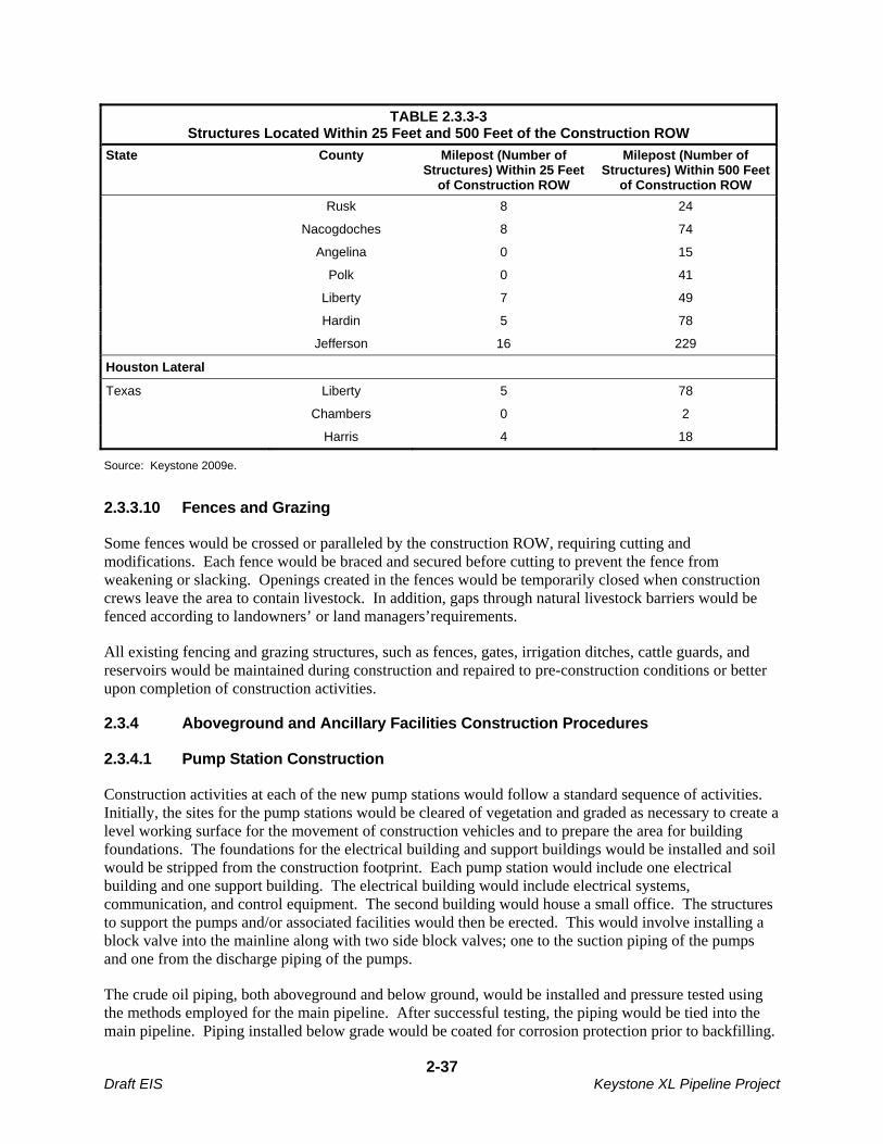
TABLE 2.3.3-3 Structures Located Within 25 Feet and 500 Feet of the Construction ROW
State County Milepost (Number of Structures) Within 25 Feet
of Construction ROW
Milepost (Number of Structures) Within 500 Feet
of Construction ROW
Rusk 8 24
Nacogdoches 8 74
Angelina 0 15
Polk 0 41
Liberty 7 49
Hardin 5 78
Jefferson 16 229
Houston Lateral
Texas Liberty 5 78
Chambers 0 2
Harris 4 18
Source: Keystone 2009e.
2.3.3.10 Fences and Grazing
Some fences would be crossed or paralleled by the construction ROW, requiring cutting and modifications. Each fence would be braced and secured before cutting to prevent the fence from weakening or slacking. Openings created in the fences would be temporarily closed when construction crews leave the area to contain livestock. In addition, gaps through natural livestock barriers would be fenced according to landowners’ or land managers’requirements.
All existing fencing and grazing structures, such as fences, gates, irrigation ditches, cattle guards, and reservoirs would be maintained during construction and repaired to pre-construction conditions or better upon completion of construction activities.
2.3.4 Aboveground and Ancillary Facilities Construction Procedures
2.3.4.1 Pump Station Construction
Construction activities at each of the new pump stations would follow a standard sequence of activities. Initially, the sites for the pump stations would be cleared of vegetation and graded as necessary to create a level working surface for the movement of construction vehicles and to prepare the area for building foundations. The foundations for the electrical building and support buildings would be installed and soil would be stripped from the construction footprint. Each pump station would include one electrical building and one support building. The electrical building would include electrical systems, communication, and control equipment. The second building would house a small office. The structures to support the pumps and/or associated facilities would then be erected. This would involve installing a block valve into the mainline along with two side block valves; one to the suction piping of the pumps and one from the discharge piping of the pumps.
The crude oil piping, both aboveground and below ground, would be installed and pressure tested using the methods employed for the main pipeline. After successful testing, the piping would be tied into the main pipeline. Piping installed below grade would be coated for corrosion protection prior to backfilling.
2-37 Draft EIS Keystone XL Pipeline Project

In addition, all below grade facilities would be protected by a cathodic protection system. Pumps, controls, and safety devices would be checked and tested to ensure proper system operation and activation of safety mechanisms before being put into service.
Construction activities and the storage of building materials would be confined to the pump station construction sites. Figures 2.2.3-1 and 2.2.3-2 illustrate typical plot plans for pump stations. After hydrostatic testing, final grading would occur around each pump station and security fences would be installed.
2.3.4.2 Tank Farm Construction
The tank farm site would be co-located with pump station 26 at Steele City, Nebraska. The tank farm site would be cleared and graded to create a level work surface for the tanks. Topsoil from the site would be stored adjacent to the site area. The tank structures would be welded steel tanks with internal floating roofs. They would be installed inside an impervious bermed area which would act as secondary containment. The piping in the tank farm area would be both above and below ground. The tanks and associated piping would be isolated electrically from the pipeline and protected by their own cathodic protection system. The electrical and control system for the tanks and associated piping would share the facilities required for the adjacent pump station.
After successful hydrostatic testing of the tanks and associated piping, and commissioning of the control system, the tanks would be connected with the pipeline system. Each tank would have a separate water screen and fire suppression system supplied by an on-site fire water supply pond. A separate larger pond would be installed to manage storm water and mitigate any potential contamination from the site. Figure 2.3.4-1 shows the general arrangement of the Steele City Tank Farm. After the completion of startup and testing, the tank farm would be final graded and a permanent security fence would be installed.
2.3.4.3 Mainline Valves, Pigging and Densitometer Facilities, and Delivery Sites
MLV construction would occur during mainline pipeline construction. To facilitate year-round access, the MLVs would be located as near as practicable to existing public roads and within the permanent ROW. If necessary, new access roads would be constructed into the fenced MLV sites.
The co-located crude oil delivery, pigging, and densitometer facilities would be totally enclosed within the adjacent pump station or tank farm. The construction sequence would include clearing and grading followed by trenching, piping installation, building fabrication, fencing, cleanup, and site restoration.
2.3.5 Construction Schedule and Workforce
According to Keystone’s current proposed schedule, construction of the Gulf Coast Segment would begin in 2010, while the Steele City Segment would commence in 2011 and the Houston Lateral would begin in 2012. Construction of the two new pump stations along the Keystone Cushing Extension would coincide with construction of the remainder of the proposed Project.
The Project would be constructed in 17 spreads, as shown in Table 2.3.5-1 with 10 spreads in the Steele City Segment, six spreads in the Gulf Coast Segment, and the Houston Lateral constructed in one spread. All spreads within the same segment would be constructed simultaneously.
Cross-country pipeline construction would typically proceed at a pace of approximately 20 constructed miles per calendar month per spread. Construction would occur in this approximate sequence:
2-38 Draft EIS Keystone XL Pipeline Project
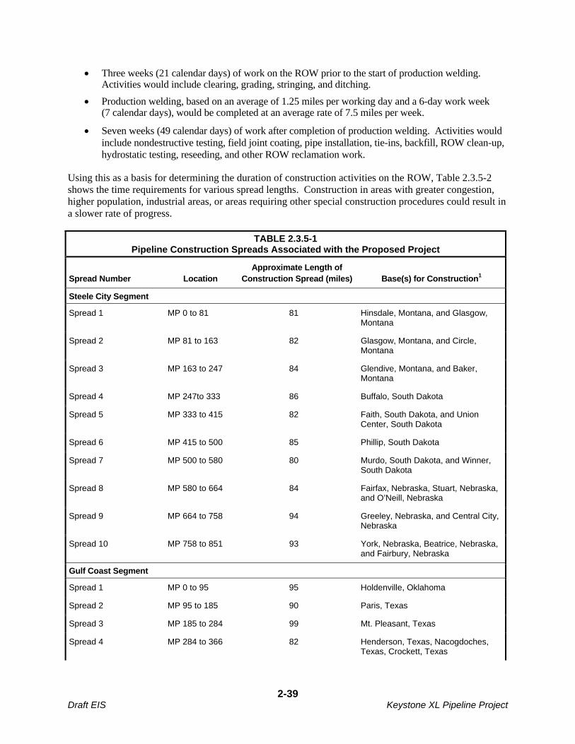
Three weeks (21 calendar days) of work on the ROW prior to the start of production welding. Activities would include clearing, grading, stringing, and ditching.
Production welding, based on an average of 1.25 miles per working day and a 6-day work week (7 calendar days), would be completed at an average rate of 7.5 miles per week.
Seven weeks (49 calendar days) of work after completion of production welding. Activities would include nondestructive testing, field joint coating, pipe installation, tie-ins, backfill, ROW clean-up, hydrostatic testing, reseeding, and other ROW reclamation work.
Using this as a basis for determining the duration of construction activities on the ROW, Table 2.3.5-2 shows the time requirements for various spread lengths. Construction in areas with greater congestion, higher population, industrial areas, or areas requiring other special construction procedures could result in a slower rate of progress.
TABLE 2.3.5-1 Pipeline Construction Spreads Associated with the Proposed Project
Spread Number Location Approximate Length of
Construction Spread (miles) Base(s) for Construction1
Steele City Segment
Spread 1 MP 0 to 81 81 Hinsdale, Montana, and Glasgow, Montana
Spread 2 MP 81 to 163 82 Glasgow, Montana, and Circle, Montana
Spread 3 MP 163 to 247 84 Glendive, Montana, and Baker, Montana
Spread 4 MP 247to 333 86 Buffalo, South Dakota
Spread 5 MP 333 to 415 82 Faith, South Dakota, and Union Center, South Dakota
Spread 6 MP 415 to 500 85 Phillip, South Dakota
Spread 7 MP 500 to 580 80 Murdo, South Dakota, and Winner, South Dakota
Spread 8 MP 580 to 664 84 Fairfax, Nebraska, Stuart, Nebraska, and O’Neill, Nebraska
Spread 9 MP 664 to 758 94 Greeley, Nebraska, and Central City, Nebraska
Spread 10 MP 758 to 851 93 York, Nebraska, Beatrice, Nebraska, and Fairbury, Nebraska
Gulf Coast Segment
Spread 1 MP 0 to 95 95 Holdenville, Oklahoma
Spread 2 MP 95 to 185 90 Paris, Texas
Spread 3 MP 185 to 284 99 Mt. Pleasant, Texas
Spread 4 MP 284 to 366 82 Henderson, Texas, Nacogdoches, Texas, Crockett, Texas
2-39 Draft EIS Keystone XL Pipeline Project
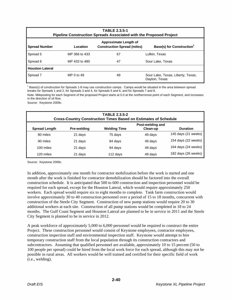
TABLE 2.3.5-1 Pipeline Construction Spreads Associated with the Proposed Project
Spread Number Location Approximate Length of
Construction Spread (miles) Base(s) for Construction1
Spread 5 MP 366 to 433 67 Lufkin, Texas
Spread 6 MP 433 to 480 47 Sour Lake, Texas
Houston Lateral
Spread 7 MP 0 to 49 49 Sour Lake, Texas, Liberty, Texas, Dayton, Texas
1 Base(s) of construction for Spreads 1-8 may use construction camps. Camps would be situated in the area between spread breaks for Spreads 1 and 2, for Spreads 3 and 4, for Spreads 5 and 6, and for Spreads 7 and 8.
Note: Mileposting for each Segment of the proposed Project starts at 0.0 at the northernmost point of each Segment, and increases in the direction of oil flow.
Source: Keystone 2009c.
TABLE 2.3.5-2 Cross-Country Construction Times Based on Estimates of Schedule
Spread Length Pre-welding Welding Time Post-welding and
Clean-up Duration
80 miles 21 days 75 days 49 days 145 days (21 weeks)
90 miles 21 days 84 days 49 days 154 days (22 weeks)
100 miles 21 days 94 days 49 days 164 days (24 weeks)
120 miles 21 days 112 days 49 days 182 days (26 weeks)
Source: Keystone 2009c.
In addition, approximately one month for contractor mobilization before the work is started and one month after the work is finished for contractor demobilization should be factored into the overall construction schedule. It is anticipated that 500 to 600 construction and inspection personnel would be required for each spread, except for the Houston Lateral, which would require approximately 250 workers. Each spread would require six to eight months to complete. Tank farm construction would involve approximately 30 to 40 construction personnel over a period of 15 to 18 months, concurrent with construction of the Steele City Segment. Construction of new pump stations would require 20 to 30 additional workers at each site. Construction of all pump stations would be completed in 18 to 24 months. The Gulf Coast Segment and Houston Lateral are planned to be in service in 2011 and the Steele City Segment is planned to be in service in 2012.
A peak workforce of approximately 5,000 to 6,000 personnel would be required to construct the entire Project. These construction personnel would consist of Keystone employees, contractor employees, construction inspection staff and environmental inspection staff. Keystone would attempt to hire temporary construction staff from the local population through its construction contractors and subcontractors. Assuming that qualified personnel are available, approximately 10 to 15 percent (50 to 100 people per spread) could be hired from the local work force for each spread, although this may not be possible in rural areas. All workers would be well trained and certified for their specific field of work (i.e., welding).
2-40 Draft EIS Keystone XL Pipeline Project

2.3.6 Construction Conditions Imposed by PHMSA
PHMSA is the federal agency responsible for assuring the safe operations and maintenance of oil pipeline systems. PHMSA would require compliance with a set of conditions prior to granting Keystone permission to operate the Project. The conditions that PHMSA has determined would apply to the pipeline as of the publication of the DEIS are presented in this section (see below sections 2.3.6.1 – 2.3.6.4). Some of these conditions may duplicate construction and operations protocols already committed to by Keystone.
2.3.6.1 Construction Operator Qualifications
Keystone must have and follow an Operator Qualification (OQ) Program for construction tasks that can affect pipeline integrity. The Construction OQ program must comply with 49 CFR § 195.501 and must be followed throughout the construction process for the qualification of individuals performing tasks on the special permit segment areas.
If the performance of a construction task associated with implementing the alternative MOP as part of the special permit can affect the integrity of the pipeline segment, the operator must treat that task as a “covered task”, notwithstanding the definition in § 195.501(b), and implement the requirements of Subpart G as appropriate. Keystone shall have qualification records available for each individual performing covered tasks during and after the construction of the pipeline, whether company or contract employee.
A construction quality assurance plan, to ensure quality standards and controls of the pipeline, must be followed throughout the construction phase with respect to the following: pipe inspection, hauling and stringing, field bending, welding, non-destructive examination of girth welds, applying and testing field applied coating, lowering of the pipeline into the ditch, padding and backfilling, and hydrostatic testing. These tasks can affect the integrity of the pipeline segment and must be treated as covered tasks. Likewise, other task performed directly on the pipe affecting its integrity, but not listed here, are to be considered covered tasks when determined by the operator.
Other tasks that can affect pipeline integrity which must be treated as covered tasks include, but are not limited to, surveying, locating foreign lines, one call notifications, ditching/excavation, alternating current (AC) interference mitigation, cathodic protection (CP) system surveys and installation, directional drills, anomaly evaluations and repairs, right-of-way clean up, and quality assurance monitoring.
All girth welds must be inspected, repaired and non-destructively examined in accordance with §§ 195.228, 195.230 and 195.234. The NDE examiner must have all required and current certifications.
2.3.6.2 Soil Cover
The soil cover must be maintained at a minimum depth of 48 inches in all areas except consolidated rock. The minimum depth in consolidated rock areas is 36 inches. In areas where conditions prevent the maintenance of 48 inches of cover, Keystone must employ additional protective measures to alert the public and excavators to the presence of the pipeline. The additional measures shall include:
2-41 Draft EIS Keystone XL Pipeline Project
a) Placing warning tape and additional pipeline markers along the affected pipeline segment.
b) In areas where threats from chisel plowing or other activities are threats to the pipeline, the top of the pipeline must be installed and maintained at least one foot below the deepest penetration above the pipeline.
If a routine patrol or other observed conditions indicates the possible loss of cover over the pipeline, Keystone must perform a depth of cover study and replace cover as necessary to meet the minimum depth of cover requirements specified herein. If replacing cover is not practical, Keystone must submit to the appropriate Directors, PHMSA Central, Western, and Southwest Regions, alternate plans to assure safety in these areas within 60 days of the depth of cover finding.
2.3.6.3 Hydrostatic Testing
The pre-in service hydrostatic test must be to a pressure producing a hoop stress of a minimum 100 percent Specified Minimum Yield Strength (SMYS) and 1.25 times Maximum Operating Pressure (MOP) for 8 continuous hours in areas to operate up to 80 percent SMYS. The hydrostatic test results from each test must be submitted to the applicable Director(s), PHMSA Central, Western and Southwest Regions after completion of each pipeline in electronic format.
Assessment of Test Failures: Any pipe failure occurring during the pre-in service hydrostatic test must undergo a root cause failure analysis to include a metallurgical examination of the failed pipe. The results of this examination must preclude a systemic pipeline material issue and the results must be reported to PHMSA headquarters and the applicable Director(s), PHMSA Central, Western, and Southwest Regions within 60 days of the failure and prior to operating at the alternative MOP.
2.3.6.4 Geometry Tool Run
For initial construction and the initial geometry tool run, any dent with a depth greater than 2 percent of the nominal pipe diameter must be removed unless the dent is repaired by a method that reliable engineering tests and analyses show can permanently restore the serviceability of the pipe. For the purposes of this condition, a “dent” is a depression that produces a gross disturbance in the curvature of the pipe wall without reducing the pipe wall thickness. The depth of the dent is measured as the gap between the lowest point of the dent and the prolongation of the original contour of the pipe.
2.3.6.5 Deformation Tool Run, Evaluation, and Remediation
Keystone must conduct a pipe expansion survey prior to operating at the alternative MOP in accordance with the following:
a) A deformation tool run would be required prior to operating above 72 percent SMYS at the alternative MOP and the results of the tool findings must be reviewed to ensure no low or variable yield strength pipe joints are located in the pipeline. The deformation tool must have sensors that can detect expanded pipe at a minimum of 8 percent expansion, and with a sensing tolerance of 1 percent.
2-42 Draft EIS Keystone XL Pipeline Project
b) Pipe joints found to have low yield strength would require removal from the pipeline prior to operating above 72 percent SMYS.
All expanded pipe above 0.75 percent diameter (0.27-inch) for 36-inch pipe must be noted on the deformation tool report. A remediation plan must be prepared by Keystone for all pipe expanded above 0.75 percent diameter that may have low yield strength pipe based upon industry research or a Keystone assessment plan of known expanded pipe. The results of this deformation tool survey and remediation plan must be analyzed and submitted to the appropriate Director(s), PHMSA Central, Western, and Southwest Regions 60 days prior to operating at the alternative MOP.
2.3.6.6 Line Markers
Keystone must employ line-of-sight markings on the pipeline in the special permit segment(s) except in agricultural areas or large water crossings such as lakes where line of sight signage is not practical. The marking of pipelines is also subject to Federal Energy Regulatory Commission orders or environmental permits and local restrictions. Additional markers must be placed along the pipeline in areas where the pipeline is buried less than 48 inches.
2.4 OPERATIONS AND MAINTENANCE
The proposed Project’s facilities would be maintained in accordance with 49 CFR Parts 194 and 195 and other applicable federal and state regulations.
An annual Pipeline Maintenance Program (PMP) would be implemented by Keystone to ensure the integrity of the pipeline. The PMP would include valve maintenance, periodic inline inspections, and cathodic protection readings to ensure facilities are reliable and in service. Data collected in each year of the program would be fed back into the decision-making process for the development of the following year’s program. In addition, the pipeline would be monitored 24 hours a day, 365 days a year from the Operations Control Center (OCC) using leak detection systems and SCADA. During operations, a Project-specific ERP would be in place to manage a variety of events. Operation and maintenance of the pipeline system would typically be accomplished by Keystone personnel. The permanent operational pipeline workforce would comprise about 20 U.S. employees, strategically located along the length of the pipeline in the U.S.
2.4.1 Normal Operations and Routine Maintenance
The preparation of manuals and procedures for conducting normal operations and maintenance activities would comply with the CFR, and the pipeline would be regularly inspected via aerial and ground surveillance at a frequency consistent with 49 CFR Part 195. These surveillance activities are in place to provide prompt identification of possible encroachments or nearby construction activities, ROW erosion, exposed pipe or any other conditions that could result in damage to the pipeline. MLVs at pump stations fall under the inspection requirements as well as the intermediate MLVs. The DOT regulation at 49 CFR Section 195.420(b) requires inspection at intervals not to exceed 7.5 months but at least twice each calendar year. Landowners would be encouraged to report any pipeline integrity concerns to Keystone or to the USDOT/OPS. In addition, aerial surveillance of the pipeline ROW would be carried out at least 26 times a year.
Federal regulations require that pipeline operators identify areas along the proposed pipeline corridor that would be considered High Consequence Areas (HCAs). While some of these areas need to be defined through sophisticated risk modeling, in general they are specific locales where the release of fluid from a
2-43 Draft EIS Keystone XL Pipeline Project
hazardous liquid pipeline could produce significant adverse consequences (e.g., navigable waterways, high population areas, etc.). Prior to receipt of an operating permit from OPS, Keystone would need to identify the HCAs along the proposed route. Population changes along the route would be monitored throughout pipeline operation and any additional HCAs identified as necessary. All operation and maintenance work would be performed in accordance with OPS requirements. Woody vegetation along the permanent easement would be cleared periodically in order to maintain accessibility for pipeline integrity surveys. Mechanical mowing or cutting would be carried out from time to time as needed along the permanent easement for normal vegetation maintenance. Cultivated crops would be allowed to grow in the permanent easement but any established trees would be removed from the permanent ROW in all areas. In areas where the pipeline would have been installed via HDD, trees would be cleared as required on a site specific basis.
Existing permanent erosion control devices would be monitored to identify any areas requiring repair. The remainder of the ROW would be monitored to identify areas where additional erosion control devices would be necessary to prevent future degradation. The ROW would be monitored to identify any areas where soil productivity has been degraded as a result of pipeline construction. In these areas, reclamation measures would be implemented to rectify the problems.
The Project OCC would be manned by experienced and highly trained personnel 24 hours per day, every day of the year and would be located in Calgary, Canada. In addition, a fully redundant backup OCC would be constructed, operated and maintained, also in Canada. Primary and backup communications systems would provide real-time information from the pump stations to field personnel. The control center would have highly sophisticated pipeline monitoring systems including a leak detection system capable of identifying abnormal conditions and initiating visual and audible alarms. Automatic shut down systems would be initiated if a valve starts to shut and all pumps upstream would start to turn off automatically. All other pipeline situations would require human response.
SCADA facilities would be located in the OCC. At all pump stations and delivery facilities there would be communication software that sends data back to the OCC. The pipeline SCADA system would allow the OCC to remotely read intermediate MLV positions, tank levels and delivery flow and total volume. The OCC personnel would also be able to start and stop pump stations and open and close MLVs. SCADA systems are discussed in more detail in Section 2.4.2.1.
2.4.2 Abnormal Operations
Abnormal operating procedures would be implemented in accordance with 49 CFR Section 195.402(d). Aerial surveillance of the pipeline ROW would be carried out at least 26 times a year.
Multiple overlapping and redundant systems would be implemented, including:
Quality Assurance (QA) program for pipe manufacture and pipe coating;
FBE coating;
Cathodic protection;
Non-destructive testing of 100 percent of the girth welds;
Hydrostatic testing producing a hoop stress of a minimum 100 percent SMYS and 1.25 times MOP for 8 continuous hours in areas that would operate up to 80 percent SMYS (should PHMSA grant the special permit required to exceed 72 percent SMYS);
Periodic internal cleaning and high-resolution in-line inspection;
Depth of cover exceeding federal standards;
2-44 Draft EIS Keystone XL Pipeline Project
Periodic aerial surveillance;
Public awareness program;
SCADA system; and
An OCC with complete redundant backup, providing monitoring of the pipeline every 5 seconds, 24 hours a day, every day of the year.
Software associated with the SCADA monitoring system and volumetric balancing would be utilized to assist in leak detection during pipeline operations. If pressure indications change, the pipeline controller would immediately evaluate the situation. If a leak is suspected, the ERP would be initiated, as described in Section 2.4.2.2. In the event of a pipeline segment shutdown due to a suspected leak, operation of the affected segment would not be resumed until the cause of the alarm (e.g., false alarm by instrumentation, or leak) is identified and repaired. In the case of a reportable leak, DOT approval would be required to resume operation of the affected segment.
The preparation of manuals and procedures for responding to abnormal operations would comply with the CFR, including 49 CFR Part 195.402. The manual would include procedures to provide safety when operating design limits have been exceeded. This includes investigating and correcting the cause of unintended closure of valves or shutdowns, increases or decreases in pressure or flow rate outside normal operating limits, loss of communications, operation of any safety device, and any other malfunction of a component, deviation from normal operation, or personnel error which could cause a hazard to persons or property. Procedures would also include checking variations from normal operation after abnormal operation has ended at sufficient critical locations in the system to:
Assure continued integrity and safe operation;
Identify variations from normal operation of pressure and flow equipment and controls;
Notify responsible operator personnel when notice of an abnormal operation is received;
Review periodically the response of operator personnel to determine the effectiveness of the procedures controlling abnormal operation; and
Take corrective action where deficiencies are found.
The operations manager on duty would be responsible for executing abnormal operating procedures in the event of any unusual situation.
2.4.2.1 SCADA and Leak Detection
SCADA facilities would be used to remotely monitor and control the pipeline system. This would include a redundant fully functional backup system available for service at all times. Automatic features would be installed as integral components within the SCADA system to ensure operation within prescribed pressure limits. Additional automatic features would be installed at the local pump station level and would provide pipeline pressure protection in the event communications with the SCADA host are interrupted.
A number of complementary leak detection methods and systems would be available within the OCC and would be linked to the SCADA system. Remote monitoring would consist primarily of monitoring pressure and flow data received from pump stations and valve sites would be fed back to the OCC by the SCADA system. Software based volume balance systems would monitor receipt and delivery volumes and would detect leaks down to approximately 5 percent of pipeline flow rate. Computational Pipeline Monitoring or model based leak detection systems would break the pipeline system into smaller segments
2-45 Draft EIS Keystone XL Pipeline Project

and would monitor each of these segments on a mass balance basis. These systems would detect leaks down to a level approximately 1.5 to 2 percent of pipeline flow rate. Computer based, non real time, accumulated gain/loss volume trending would assist in identifying low rate or seepage releases below the 1.5 to 2 percent by volume detection thresholds. If any of the software-based leak detection methods indicates that a predetermined loss threshold has been exceeded, an alarm would be sent through SCADA and the Controller would take corrective action. The SCADA system would continuously poll all data on the pipeline at an interval of approximately 5 seconds
In the event of a leak, the operator would shut down operating pumping units and close the isolation valves. It would take approximately 9 minutes to complete the emergency shut-down procedure (shut down operating pumping units) and an additional 3 minutes to close the isolation valves.
In addition to the SCADA and complimentary leak detection systems, direct observation methods including aerial patrols, ground patrols and public and landowner awareness programs would be implemented to encourage and facilitate the reporting of suspected leaks and events that could suggest a threat to the integrity of the pipeline.
2.4.2.2 Emergency Response Procedures
Site-specific ERPs would be prepared for the system, which would be submitted to and approved by the OPS and PHMSA prior to operation. A comprehensive ERP for the first Keystone Pipeline Project has been reviewed and approved by PHMSA. The ERP contains several elements, procedures, notifications, and technical information that are directly applicable to the Project. The Keystone ERP is comprehensive, and forms the basis for preparing the site-specific information for the Project ERP. Once the specific route is finalized, field work would commence in collecting relevant information to be incorporated into the Project ERP which would then be submitted to PHMSA for their review and approval.
Several federal regulations define the notification requirements and response actions in the case of a spill, including the National Oil and Hazardous Substances Pollution Contingency Plan (40 CFR Part 300), the Clean Water Act (CWA), and the Oil Pollution Act. These programs command notification and initiation of response actions in a timeframe and on a scale commensurate with the threats posed.
In the event of a release, several procedures would be implemented to mitigate damage, including a line shut down. Procedures would also include immediate dispatch of a first responder to verify the release and secure the site. Simultaneously, an Incident Command System would be implemented and internal and external notifications would take place. The National Response Center (NRC) would be notified if the release meets one of the prescribed criteria. Keystone and the NRC would also notify other regional and local emergency response agencies as quickly as possible. All of this information would be included in the Project ERP. In addition, response equipment would also be procured and strategically positioned along the route, staff would be trained in spill response and Incident Command System, and emergency services and public officials would be educated on all aspects of the proposed Project and their role in the unlikely event of a release. In the unlikely event of a spill, Keystone and its contractors would be responsible for recovery and cleanup.
In the event of a suspected leak or if a leak is reported to the OCC, there would be an emergency pipeline shutdown. This would involve stopping all operating pumping units at all pump stations. The on-call response designate would respond to and verify an incident. Once the OCC notifies the individual and an assessment of the probability and risk is established, field personnel could elect to dispatch other resources as soon as practical. Response efforts would first be directed to preventing or limiting any
2-46 Draft EIS Keystone XL Pipeline Project

further contamination of the waterway, once any concerns with respect to health and safety of the responders have been addressed.
The specific locations of Keystone’s emergency responders and equipment would be determined upon conclusion of the pipeline detailed design and the completion of the ERP. Company emergency responders would be placed consistent with industry practice and in compliance with the applicable regulations, including 49 CFR Parts 194 and 195. The response time to transfer additional resources to a potential leak site would follow an escalating tier system, with initial emergency responders capable of reaching all locations within 6 hours in the event of a spill. Typically, emergency responders would be based in closer proximity to the following areas:
Commercially navigable waterways and other water crossings;
Populated and urbanized areas; and
Unusually sensitive areas, including drinking water locations, ecological, historical, and archaeological resources.
Emergency response equipment would be strategically situated along the pipeline route. Types of emergency response equipment include pick-up trucks, one-ton trucks and vans; vacuum trucks; work and safety boats; containment boom; skimmers; pumps, hoses, fittings and valves; generators and extension cords; air compressors; floodlights; communications equipment including cell phones, two way radios and satellite phones; containment tanks and rubber bladders; expendable supplies including absorbent booms and pads; assorted hand and power tools including shovels, manure forks, sledge hammers, rakes, hand saws, wire cutters, cable cutters, bolt cutters, pliers and chain saws; ropes, chains, screw anchors, clevis pins and other boom connection devices; personnel protective equipment (PPE) including rubber gloves, chest and hip waders and H2S, O2, LEL and benzene detection equipment; and wind socks, signage, air horns, flashlights, megaphones and fluorescent safety vests. Emergency response equipment would be maintained and tested in accordance with manufacturers recommendations.
Additional equipment including helicopters, fixed wing aircraft, all-terrain vehicles (ATVs), snowmobiles, backhoes, dump trucks, watercraft, bull dozers, and front-end loaders could also be accessed depending upon site-specific circumstances. Other types, numbers and locations of equipment would be determined upon conclusion of the pipeline detailed design and the completion of the Project ERP.
A fire associated with a spill is relatively rare. Only about 4 percent of reportable liquid spills are ignited (OPS 2005). In the event of a fire, local emergency responders would execute the roles listed above and firefighters would take actions to prevent the crude oil fire from spreading to residential areas.
2.4.2.3 Remediation
Corrective remedial actions would be dictated by federal, state, and local regulations and enforced by the USEPA, OPS and appropriate state and/or local agencies. Required remedial actions may be large or small, dependant upon a number or factors including state-mandated remedial cleanup levels, potential effects to sensitive receptors, volume and extent of the contamination, potential violation of water quality standards, and the magnitude of adverse impacts caused by remedial activities. A large remediation action may include the excavation and removal of contaminated soil, for example, or could involve allowing the contaminated soil to recover through natural attenuation or environmental fate processes such as evaporation and biodegradation.
2-47 Draft EIS Keystone XL Pipeline Project
The appropriate remedial measures would be implemented to meet federal, state, and local standards designed to ensure protection of human health and environmental quality.
2.4.3 Operations and Maintenance Conditions Imposed by PHMSA
2.4.3.1 Overpressure Conditions
The pipeline should be equipped with field devices aimed at limiting overpressure conditions. Remotely actuated valves should be fitted with devices that would stop the transit (intentional or uncommanded) of the mainline valve should an overpressure condition occur or an impending overpressure condition is expected. Sufficient pressure sensors, on both the upstream and downside side of valves, must be installed to ensure that an overpressure situation did not occur. Also, sufficient pressure sensors shall be installed along the pipeline to conduct real time hydraulic modeling, and if needed to conduct a surge analysis to determine pipeline segments that may have experienced an overpressure condition. PHMSA is imposing conditions on overpressure protection control per the following:
a) Overpressure Protection Control: Mainline pipeline overpressure protection must be limited to a maximum of 110 percent MOP consistent with § 195.406(b). A surge analysis showing how the pipeline special permit segment(s) would be operated to be consistent with these conditions is required prior to operating at the alternative MOP. The surge analysis and operational procedures must be provided to the appropriate Directors, PHMSA Central, Western, and Southwestern Regions at least 60 days prior to implementation of the alternate MOP.
b) If a measured or calculated MOP exceedance occurs, the pipeline shall be patrolled prior to restart.
2.4.3.2 SCADA
Scan rate shall be fast enough to minimize overpressure conditions (overpressure control system), provide very responsive abnormal operation indications to controllers and detect small leaks within technology limitations.
Must meet the requirements of regulations developed as a result of the findings of the National Transportation Safety Board, Supervisory Control and Data Acquisition (SCADA) in Liquid Pipelines, Safety Study, NTSB/SS-05/02 specifically including:
a) Operator displays shall adhere to guidance provided in API Recommended Practice 1165, Recommended Practice for Pipeline SCADA Displays. This shall be implemented and performed at any location on the Keystone XL system where a SCADA system is used and where an individual is assigned the responsibility to monitor and respond to SCADA information (tanks terminals or facilities also).
b) Operators must have a policy for the review/audit of alarms for false alarm reduction and near miss or lessons learned criteria. This alarm review shall be implemented and performed at any location on the Keystone XL system where a SCADA system is used and where an individual(s) is assigned the responsibility to monitor and respond to alarm information (tanks terminals or facilities also).
2-48 Draft EIS Keystone XL Pipeline Project

c) SCADA controller training shall include simulator for controller recognition of abnormal operating conditions, in particular leak events. A generic simulator or simulation shall not be allowed by itself as a means to meet this requirement. A full simulator (console screens respond and react as actual console screens) shall be required and used for training of abnormal operating conditions (AOCs) wherever possible.
d) Have a plan for fatigue management.
e) Install computer-based leak detection system on all lines unless an engineering analysis determines that such a system is not necessary.
Develop and implement shift change procedures for controllers that are scientifically based, sets appropriate work and rest schedules, and consider circadian rhythms and human sleep and rest requirements in-line with guidance provided by NTSB recommendation P-99-12 issued June 1, 1999.
Verify point-to-point display screens and SCADA system inputs before placing the line in service. This shall be implemented and performed at any location on the Keystone XL system where a SCADA system is used and where an individual(s) is assigned the responsibility to monitor and respond to alarm information (tanks terminals or facilities also).
a) Implement individual controller log-in provisions.
b) Establish and maintain a secure operating control room environment.
c) Establish and maintain the ability to make modifications and test these modifications in an off-line mode. The special permit segments must have controls in-place and be functionally tested in an off-line mode prior to any changes being implemented after the line is in service and prior to beginning the line fill stage.
d) Provide SCADA computer process load information tracking.
Mainline valves located on either side of pipeline segment containing an HCA where personnel response time to the valve exceeds one hour must be remotely controlled by the Supervisory Control and Data Acquisition (SCADA) system. The SCADA system must be capable of closing the valve and monitoring the valve position, upstream pressure and downstream pressure. If Keystone does not install remote controlled valves on the XL system, Keystone must document on a yearly basis, not to exceed 15 months that personnel response time to these valves would not take over one hour. Remote power backup is required to ensure communications are maintained during inclement weather.
2.5 CONNECTED ACTIONS
DOS has identified several actions separate from the proposed Keystone XL Project that are not part of the Presidential Permit application submitted by Keystone and determined that the following projects are connected actions for the purposes of this NEPA review:
2-49 Draft EIS Keystone XL Pipeline Project
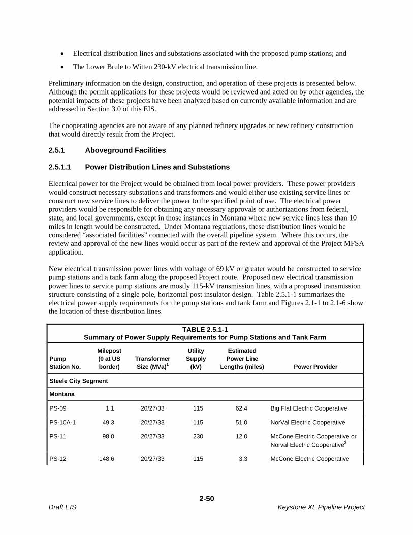
Electrical distribution lines and substations associated with the proposed pump stations; and
The Lower Brule to Witten 230-kV electrical transmission line.
Preliminary information on the design, construction, and operation of these projects is presented below. Although the permit applications for these projects would be reviewed and acted on by other agencies, the potential impacts of these projects have been analyzed based on currently available information and are addressed in Section 3.0 of this EIS.
The cooperating agencies are not aware of any planned refinery upgrades or new refinery construction that would directly result from the Project.
2.5.1 Aboveground Facilities
2.5.1.1 Power Distribution Lines and Substations
Electrical power for the Project would be obtained from local power providers. These power providers would construct necessary substations and transformers and would either use existing service lines or construct new service lines to deliver the power to the specified point of use. The electrical power providers would be responsible for obtaining any necessary approvals or authorizations from federal, state, and local governments, except in those instances in Montana where new service lines less than 10 miles in length would be constructed. Under Montana regulations, these distribution lines would be considered “associated facilities” connected with the overall pipeline system. Where this occurs, the review and approval of the new lines would occur as part of the review and approval of the Project MFSA application.
New electrical transmission power lines with voltage of 69 kV or greater would be constructed to service pump stations and a tank farm along the proposed Project route. Proposed new electrical transmission power lines to service pump stations are mostly 115-kV transmission lines, with a proposed transmission structure consisting of a single pole, horizontal post insulator design. Table 2.5.1-1 summarizes the electrical power supply requirements for the pump stations and tank farm and Figures 2.1-1 to 2.1-6 show the location of these distribution lines.
TABLE 2.5.1-1 Summary of Power Supply Requirements for Pump Stations and Tank Farm
Pump Station No.
Milepost (0 at US border)
Transformer Size (MVa)1
Utility Supply
(kV)
Estimated Power Line
Lengths (miles) Power Provider
Steele City Segment
Montana
PS-09 1.1 20/27/33 115 62.4 Big Flat Electric Cooperative
PS-10A-1 49.3 20/27/33 115 51.0 NorVal Electric Cooperative
PS-11 98.0 20/27/33 230 12.0 McCone Electric Cooperative or Norval Electric Cooperative2
PS-12 148.6 20/27/33 115 3.3 McCone Electric Cooperative
2-50 Draft EIS Keystone XL Pipeline Project

TABLE 2.5.1-1 Summary of Power Supply Requirements for Pump Stations and Tank Farm
Pump Station No.
Milepost (0 at US border)
Transformer Size (MVa)1
Utility Supply
(kV)
Estimated Power Line
Lengths (miles) Power Provider
PS-13A-2 199.3 20/27/33 115 13.5 Tongue River Electric Cooperative
PS-14A-1 236.8 20/27/33 115 5.2 Montana-Dakota Utilities Company
South Dakota
PS-15A-2 285.6 20/27/33 115 23.0 Grand Electric Cooperative
PS-16 333.3 20/27/33 115 45.7 Grand Electric Cooperative
PS-17A-2 386.9 20/27/33 115 11.0 Grand Electric Cooperative
PS-18 440.0 20/27/33 115 25.9 West Central Electric Cooperative
PS-19A-3 495.8 20/27/33 115 20.2 West Central Electric Cooperative
PS-20A-2 546.4 20/27/33 115 15.9 Rosebud Electric Cooperative
PS-21A-1 591.7 20/27/33 115 20.1 Rosebud Electric Cooperative
Nebraska
PS-22 642.1 20/27/33 115 7.4 Nebraska Public Power District
PS-23 694.0 20/27/33 115 23.0 Nebraska Public Power District
PS-24A-1 751.1 20/27/33 115 10.1 Nebraska Public Power District
PS-25A-1 799.7 20/27/33 69 14.3 Nebraska Public Power District
PS-26 850.6 20/27/33 115 13.3 Nebraska Public Power District
Keystone Cushing Extension
Kansas
PS-27A-1 49.0* 20/27/33 115 10.2 Clay Center Public Utility
PS-29A-2 144.5* 20/27/33 115 11.2 Westar Energy
Gulf Coast Segment
Oklahoma
2-51 Draft EIS Keystone XL Pipeline Project
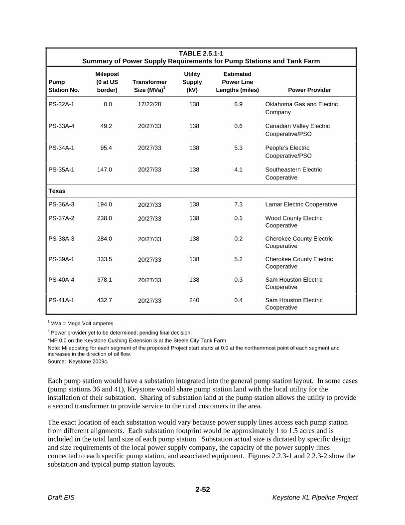
TABLE 2.5.1-1 Summary of Power Supply Requirements for Pump Stations and Tank Farm
Pump Station No.
Milepost (0 at US border)
Transformer Size (MVa)1
Utility Supply
(kV)
Estimated Power Line
Lengths (miles) Power Provider
PS-32A-1 0.0 17/22/28 138 6.9 Oklahoma Gas and Electric Company
PS-33A-4 49.2 20/27/33 138 0.6 Canadian Valley Electric Cooperative/PSO
PS-34A-1 95.4 20/27/33 138 5.3 People’s Electric Cooperative/PSO
PS-35A-1 147.0 20/27/33 138 4.1 Southeastern Electric Cooperative
Texas
PS-36A-3 194.0 20/27/33 138 7.3 Lamar Electric Cooperative
PS-37A-2 238.0 20/27/33 138 0.1 Wood County Electric Cooperative
PS-38A-3 284.0 20/27/33 138 0.2 Cherokee County Electric Cooperative
PS-39A-1 333.5 20/27/33 138 5.2 Cherokee County Electric Cooperative
PS-40A-4 378.1 20/27/33 138 0.3 Sam Houston Electric Cooperative
PS-41A-1 432.7 20/27/33 240 0.4 Sam Houston Electric Cooperative
1 MVa = Mega Volt amperes. 2 Power provider yet to be determined; pending final decision.
*MP 0.0 on the Keystone Cushing Extension is at the Steele City Tank Farm.
Note: Mileposting for each segment of the proposed Project start starts at 0.0 at the northernmost point of each segment and increases in the direction of oil flow.
Source: Keystone 2009c.
Each pump station would have a substation integrated into the general pump station layout. In some cases (pump stations 36 and 41), Keystone would share pump station land with the local utility for the installation of their substation. Sharing of substation land at the pump station allows the utility to provide a second transformer to provide service to the rural customers in the area.
The exact location of each substation would vary because power supply lines access each pump station from different alignments. Each substation footprint would be approximately 1 to 1.5 acres and is included in the total land size of each pump station. Substation actual size is dictated by specific design and size requirements of the local power supply company, the capacity of the power supply lines connected to each specific pump station, and associated equipment. Figures 2.2.3-1 and 2.2.3-2 show the substation and typical pump station layouts.
2-52 Draft EIS Keystone XL Pipeline Project

Other electrical power requirements, such as power for MLVs, would be supplied from distribution service drops from adjacent distribution power lines with voltage below 69 kV. Each distribution service drop would typically be less than 200 feet long, and would require the installation of one or two poles and a transformer. The electric utility typically installs a pole mounted transformer within 200 feet of the valve site location. However, in some cases the electric utility would install the transformer on an existing pole which would be over 200 feet from the valve site. The decision on where the transformer pole would be located is generally based on the most economical installation. For example, MLVs north of the Milk River in Montana would be supplied from transformers on poles along small lines that currently supply power to irrigation systems. Upon completion of the new service drops, the electrical power providers would restore the work area as required, in accordance with local permits.
Preliminary routing for new electrical transmission power lines was identified in consultation with each utility company. Where practicable, these preliminary power line routes have been positioned along existing county roads, section lines, or field edges, to minimize interference with adjacent agricultural lands. These routes are subject to change as pumping station supply requirements are further reviewed with power providers and in some cases, as a result of environmental review of the routes.
Electromagnetic induction can occur from power lines, which can cause noise, radio, and television interference. This potential interference would be mitigated by siting the power line away from residences (500 feet minimum, if possible) and by routing the power line to reduce parallel metallic interferences. Power line Radio Frequency Interference (RFI) is usually caused by sparking (arcs). Typically this is caused by loose hardware. The power provider design uses spring washers to keep hardware tight. Conductor supports use specialized clamps to keep the conductor and support clamps with a firm contact between the two entities at all times, to mitigate arcing sources. Defective lightning arrestors could also contribute to RFI. The power providers would use a static conductor at the top of the pole to mitigate lightning-caused flashovers. Lightning arrestors would be limited to the stations where major equipment is located. The radio communication systems at the proposed Project facilities would operate on specific frequencies licensed by the Federal Communications Commission (FCC). This would reduce the risk of any interference with radio, television or any other communication system in the area.
2.5.1.2 Lower Brule to Witten 230-kV Transmission Line
After receipt of the power requirements for the proposed Project pump stations in South Dakota, Western Area Power Administration (Western) conducted a joint system engineering study to determine system reliability under the proposed loads at full Project electrical energy consumption. The joint system engineering studies determined that a 230-kV transmission line originating from the Fort Thompson/Big Bend area and running south to the existing Witten Substation would be required to support voltage requirements for pump stations 20 and 21 in the Witten area when the Project is operating at maximum capacity.
To address this requirement Western proposes to modify the existing Big Bend-Fort Thompson No. 2, 230-kV transmission line turning structure, located on the south side of the dam, to a double-circuit structure. Western would then construct approximately 2.1 miles of new double-circuit transmission line south to a new substation, tentatively named Lower Brule Substation, which would also be constructed by Western. The new switchyard/substation would be a 3-breaker ring bus configuration, expandable to a breaker and a half configuration. The new 2.1-mile-long double-circuit 230-kV transmission line would be owned, constructed, and operated by Western. After construction, the ownership of the Lower Brule
2-53 Draft EIS Keystone XL Pipeline Project
Substation would be transferred to the Basin Electric Power Cooperative (BEPC) which would then own and operate it. Western would complete design of the new substation and double-circuit transmission line in 2012 and would begin construction in the spring of 2013.
BEPC proposes to construct and operate a new 230-kV transmission line from the proposed new Lower Brule Substation to the existing Witten Substation owned by Rosebud Electric Cooperative. The new Lower Brule Substation and approximately 70-mile-long Lower Brule to Witten 230-kV transmission line would assure future electric power requirements at pump stations 20 and 21 would be met without degrading system reliability when the Project is operating at maximum capacity. The new Lower Brule to Witten 230-kV transmission line would be built, owned, and operated by BEPC. The Witten Substation would also need to be expanded to accommodate the new switching equipment associated with the Lower Brule to Witten 230-kV transmission line.
The proposed substation and transmission line projects would be in Lyman and Tripp counties in south-central South Dakota. The Big Bend Dam is in Lyman County, close to the city of Fort Thompson. The Witten Substation is in Tripp County near the city of Witten.
As described in Section 4.4 of the EIS, Western and BEPC have identified two alternative corridors for the proposed Lower Brule to Witten transmission line project, and there are nine route options within each corridor between the Lower Brule and Witten substations.
2.5.2 Design and Construction Procedures
2.5.2.1 Pump Station Power Distribution Lines and Substations
Local utilities would supply electricity and communications to the pump stations and the tank farm. Table 2.5.1-1 summarizes new electrical power and distribution line requirements for these facilities.
All power lines and substations would be installed and operated by local power providers. These electrical power providers would therefore be responsible for ROW acquisition, ROW clearing, construction, site restoration, cleanup, and obtaining any necessary approvals or authorizations from federal, state, and local governments.
Construction of electrical power lines would involve the following:
ROW Acquisition/Easements: The electric power provider would obtain any necessary easements.
ROW Clearing: Limited clearing would be required along existing roads in native and improved grasslands and croplands. Tree trimming may be employed in certain locations, however, it may be necessary to remove some trees to provide adequate clearance between the conductors and underlying vegetation.
Power Line Construction: Power line poles and associated structures would be delivered on flatbed trucks. Radial arm diggers would typically be used to excavate the required holes. The poles would be either wood or steel and would be directly embedded into the holes in the ground. A mobile crane or picker truck may be needed to install the poles. Anchors may be required at angles and dead ends.
After the power line poles are in place, conductors (wires) would be strung between them. Pulling or reeling areas would be needed for installation of the conductor wires which would be attached to the poles using porcelain or fiberglass insulators.
2-54 Draft EIS Keystone XL Pipeline Project
Restoration: After completion of power line construction, the disturbed areas would be restored. All litter and other remaining materials would be removed from the construction areas and disposed of properly. Preconstruction contours would be restored as closely as possible and reseeding would follow landowner requirements.
In addition to the above construction process, detailed power line construction procedures would be developed by each power provider to address site specific conditions.
2.5.2.2 Lower Brule to Witten 230-kV Transmission Line
The proposed transmission line would be constructed within a 125-foot ROW. The specific structure type has not been determined. Single- and two-pole structures would be evaluated.
All substation and switchyard work, including the placement of concrete foundations, erecting support structures, construction of control buildings, and the installation of electrical equipment would take place within secured areas. The proposed substation site at Lower Brule and the expansion area at Witten would be cleared and leveled. Aggregate would be spread throughout undeveloped areas within the substation sites. Topsoil would be segregated from underlying soils and redistributed on disturbed areas outside the substation security fences. Soil erosion would be minimized during construction using BMPs. Substation components would be hauled to the site on local highways and roads and off-loaded using cranes and similar equipment. Concrete and aggregate from local sources would be hauled to the site via trucks.
A SCADA system would interconnect the substations. Hardwire system communications would utilize fiber optics within the Optical Overhead Ground Wire between the substations. Microwave communications equipment would be installed for SCADA redundancy and to facilitate voice and data communications by field personnel. Additional communications facilities may also be needed.
The impacts of construction and operation of the transmission line alternatives are generally addressed in Section 3.0 the EIS. However, DOS, Western, and the other cooperating agencies do not have sufficient design and construction information to establish an agency preferred alternative for the proposed transmission line project. An additional and separate NEPA environmental review of the alternatives to the proposed transmission line will be conducted after the alternative routes are further defined. The design and environmental review of the proposed 230-kV transmission line are on a different schedule than the pipeline system itself. Regional transmission system reliability concerns are not associated with the initial operation of the proposed pipeline pump stations, but rather with later stages of proposed pipeline operation at higher levels of crude oil throughput.
2.6 FUTURE PLANS AND ABANDONMENT
2.6.1 Future Plans
As proposed, the Project would initially have a nominal transport capacity of approximately 700,000 bpd of crude oil. By increasing the capacity of the pump stations in the future, Keystone could transport up to 900,000 bpd of crude oil through the pipeline. Should Keystone decide to increase pumping capacity to 900,000 bpd at a later date, the necessary pump station upgrades would be implemented in accordance with then-applicable permits, approvals, codes, and regulations.
Montana and North Dakota oil producers are reportedly seeking at least one pipeline connection (an “on-ramp”) to the Keystone XL Project along the proposed route in southeastern Montana to transport crude oil produced from the Williston Basin. Such a connection could only occur if one or more producers in the Williston Basin agreed to design, construct, and operate the necessary infrastructure to deliver crude
2-55 Draft EIS Keystone XL Pipeline Project

oil from the Williston Basin oil fields to the point of interconnection with the Keystone XL system. As a common carrier in Montana, Keystone has stated it would consider such a connection and that crude oil from the producers would have to be injected into the pipeline in batches of at least 200,000 barrels. The only modifications required for the Keystone XL Project would be a pipeline connection at an existing pump station as well as the installation of two new block valves and new two check valves at the pump station. The remaining infrastructure would be constructed and operated by the crude oil producers.
The infrastructure necessary for the transport of crude oil from the Williston Basin to the Keystone XL Project would include at a minimum the necessary oil field gathering systems, tankage, delivery pipeline, pump stations, and likely a batch tank farm at the point of interconnection. As of the date of issuance of this EIS the possibility of such a connection was at the conceptual stage and no producers had committed to the development of the required infrastructure. If a connection between the Project pipeline is pursued further, proposals to construct and operate such a facility would be submitted to the appropriate federal, state, and local agencies for review, including reviews of potential environmental impacts. The proposed facilities would be subject to approvals by federal, state, and local agencies having jurisdiction at that time, and if approved, would be implemented in accordance with then-applicable permits, approvals, codes, and regulations. Potential impacts of such a connection are addressed in general terms in Section 3.14 (Cumulative Impacts).
2.6.2 Abandonment
The proposed Project is expected to operate for 50 years or more. At this time, Keystone has not submitted plans for abandonment of the facilities at the end of the Project’s operational life. Abandonment plans would be submitted to the appropriate agencies for review and approval prior to abandonment of the Project facilities. Abandonment plans would be subject to approvals by local, state, and federal agencies having jurisdiction at that time and abandonment would be implemented in accordance with then-applicable permits, approvals, codes, and regulations
2.7 REFERENCES
49 CFR Part 194: Response Plans for Onshore Oil Pipelines
49 CFR Part 195: Transportation of Hazardous Liquids by Pipeline
49 CFR Section 195.410 Line Markers
40 CFR Part 300: Protection of Environment
40 CFR Part 112: Oil Pollution Prevention
49 USC Part 60118: Compliance and waivers
74 FR 4296 Request for Special Permit
Keystone (TransCanada Keystone Pipeline, LP). 2008. Keystone XL Project Environmental Report (ER). November 2008. Document No. 10623-006. Submitted to the U.S. Department of State and the Bureau of land Management by Keystone.
Keystone. 2009a. Response to United States Department of State Data Request 1.0. May 1, 2009. Submitted to U.S. Department of State by TransCanada Keystone Pipeline, L.P.
2-56 Draft EIS Keystone XL Pipeline Project

Keystone. 2009b. Response to United States Department of State Data Request 2.0. June 25, 2009. Submitted to U.S. Department of State by TransCanada Keystone Pipeline, L.P.
Keystone. 2009c. Supplemental Filing to ER. July 6, 2009. Document No.: 10623-006. Submitted to U.S. Department of State and Bureau of Land Management by TransCanada Keystone Pipeline, L.P.
Keystone. 2009d. General Conformity Determination (Document No. 10623-006-120A). July 2009.
Keystone. 2009e. Email response to data discrepancies in Supplemental Filing to ER. July 31, 2009.
Keystone. 2009f. Response to data request 3.0, November 3, 2009.
Office of Pipeline Safety (OPS). 2005. Hazardous Liquid Accident Data – 1986 to January 2002 and Hazardous Liquid Accident Data – Pre 1986. Available online at: www.///http://ops.dot.gov/stats/IA98.htm.
Pipeline and Hazardous Materials Safety Administration (PHMSA). 2009. PDEIS Comment Response Letter dated October 2, 2009.
2-57 Draft EIS Keystone XL Pipeline Project

2-58 Draft EIS Keystone XL Pipeline Project
This page intentionally left blank.


![Keystone Pipeline – South Dakota Pump Stations 12, 2011 Revision 0 Keystone Project Document # RE-03 [2-4-22-3] ATCO Project # 762900-SD TransCanada Pipeline Ltd. Keystone Pipeline](https://img.pdfslide.net/doc/110x75/5ad387177f8b9a665f8dcef1/keystone-pipeline-south-dakota-pump-stations-12-2011-revision-0-keystone-project.jpg)