Embed Size (px)
Citation preview

Rev. 06/29/07 Ameritek 2000 SERIES User’s Guide 1
User’s Guide
2000 SERIES
Part #: Revision Date: 06-29-07
Ameritek, LLC PO Box 979 Norwich, NY 13815

Rev. 06/29/07 Ameritek 2000 SERIES User’s Guide 2
Table of Contents Chapter 1 - System Description....................................................................................................... 4 Chapter 2 - System Components ..................................................................................................... 5
2.1 Transport Base Component ................................................................................................... 5 2.2 Tabbing Head Component ..................................................................................................... 5
Chapter 3 - Electronic Controls....................................................................................................... 7 3.1 Transport Control Panel......................................................................................................... 7
3.1.1 Main Power Rocker Switch............................................................................................. 7 3.1.2 Tab Head Power Rocker Switch ..................................................................................... 7 3.1.3 Jog Push Button Switch .................................................................................................. 7 3.1.4 Run Push Button Switch ................................................................................................. 7 3.1.5 Stop Push Button Switch................................................................................................. 7 3.1.6 Transport Speed Potentiometer ....................................................................................... 7
3.2 Operator Interface .................................................................................................................. 8 3.2.1 LCD Module ................................................................................................................... 8 3.2.2 Online Key ...................................................................................................................... 8 3.2.3 Menu Scroll Keys............................................................................................................ 9
3.2.3.1 Product Count........................................................................................................... 9 3.2.3.2 Transport Speed........................................................................................................ 9 3.2.3.3 Production Rate ........................................................................................................ 9
3.2.4 Numeric Keypad ............................................................................................................. 9 3.2.5 Menu Selection Keys ...................................................................................................... 9
Chapter 4 – System Setup ............................................................................................................. 10 4.1 Base Set-up .......................................................................................................................... 10
4.1.1 Attach Bridge ............................................................................................................... 10 4.1.2 Transport Base Height.................................................................................................. 11 4.1.3 Position Base................................................................................................................ 11 4.1.4 Feeder/ Ink Jet Base Setup ........................................................................................... 11 4.1.5 Adjust Feeder Position ................................................................................................. 11 4.1.6 Product Guide and Strap Usage ................................................................................... 12 4.1.7 Set Gap ......................................................................................................................... 12 4.1.8 Peel Point Height setup ................................................................................................ 13 4.1.9 Power-Up System......................................................................................................... 13 4.1.10 Feed Product............................................................................................................... 14 4.1.11 Adjust Registration Wheels......................................................................................... 14 4.1.12 Center Belt Adjustment............................................................................................... 17 4.1.13 Position Upper Press Roll .......................................................................................... 18
4.2 Head Set-up ......................................................................................................................... 19 4.2.1 Install Inner Spool Guides............................................................................................ 19 4.2.2 Secure Source Spool .................................................................................................... 19 4.2.3 Threading ..................................................................................................................... 19 4.2.4 Secure Waste Take-up Spool ....................................................................................... 20 4.2.5 Adjust Tab Sensor (Setup Menu Item: ADJUST TAB SENSOR) ................................. 20 4.2.6 Adjust Pitch Setting (Setup Menu Item: PITCH) ......................................................... 21 4.2.7 Tab/ Label Position (Position Munu Item: TAB POS) ................................................ 22 4.2.8 Number of Tabs (Position Menu Item: NUMBER OF TABS)...................................... 23 4.2.9 Begin Tabbing.............................................................................................................. 23
Chapter 5 - Controller Programming/Diagnostics......................................................................... 24 5.1 Setup Programming ............................................................................................................ 24
5.1.1 Pitch Setting (Setup Menu Item: PITCH)..................................................................... 24 5.1.2 Save Setup to Memory (Setup Menu Item: SAVE(M1 or M2) ..................................... 24 5.1.3 Auto Tab Calculator Product Size (Setup Menu Item: AUTO) .................................... 25 5.1.4 Product/ Tab Sensor Offset (Setup Menu Item: SENSOR)........................................... 25 5.1.5 Tab Sensor Sensitivity (Setup Menu Item: ADJUST TAB SENSOR) .......................... 26 5.1.6 Counter Reset (Setup Menu Item: RESET COUNT ?) ................................................. 27

Rev. 06/29/07 Ameritek 2000 SERIES User’s Guide 3
5.1.7 Product Sensor Selection 5.2 Position Programming ........................................................................................................ 28
5.2.1 Tab/ Label Position Entry (Position Menu Item: TAB POS)........................................ 28 5.2.2 Number of Tabs (Position Menu Item: NUMBER OF TABS)...................................... 29
5.3 Head Diagnostics/ Test ....................................................................................................... 30 5.3.1 Software Version (Test Menu Item: VERSION)........................................................... 30 5.3.2 Tab Drive Cycle Test (Test Menu Item: TAB DRIVE CYCLE).................................... 30 5.3.3 Stop Relay Test (Test Menu Item: STOP RELAY) ....................................................... 31 5.3.4 Motor/ Brake Test (Test Menu Item: MOTOR/-BRAKE) ............................................. 31 5.3.5 Base Cover Test (Test Menu Item: BASE COVER) .................................................... 31 5.3.6 Head Cover Test (Test Menu Item: HEAD COVER).................................................... 32 5.3.7 Bin Sensor Test (Test Menu Item: BIN SENSOR)........................................................ 32 5.3.8 Take-up Sensor Test (Test Menu Item: TAKE-UP)...................................................... 32 5.3.9 Product Sensor Test (Test Menu Item: PRODUCT) .................................................... 33 5.3.10 Tab/ Label Sensor Test (Test Menu Item: TAB SEN)................................................. 33 5.4.11 Encoder Test (Test Menu Item: ENCODER) ............................................................. 33 5.4.12 Factory Reset (Test Menu Item: FACTORY RESET) ................................................. 34
Chapter 6 – Troubleshooting......................................................................................................... 35 Chapter 7 – Appendix.................................................................................................................... 36

Rev. 06/29/07 Ameritek 2000 SERIES User’s Guide 4
Chapter 1 - System Description The Ameritek 2000 SERIES is designed to apply pressure sensitive tabs/ labels/ stamps on to flat product. You can use the system as a wrap around tabbing device or use it as a labeler. The system is made up of two major components, the transport base and the tabbing head. If the system is used as a flat tabber, labeler, or stamp affixer, the head is movable and can be located to position the label anywhere on the piece. Wrap around tabbing is always done on the right side of the mail piece. Tab/ Label/ Stamp position over the length of the product is adjusted electrically through the operator interface. The product is introduced into the system by a feeder, conveyor, or ink jet system. The product is justified to a side guide by adjusting the transport table position and the registration wheel assembly. Product thickness is adjusted with a knob that raises and lowers the height of the tab sensor assembly and another knob for the upper output transport assembly. When the product is transported, it is detected by a through-beam sensor that tells the tabbing head to apply a tab. If more than one tab is to be applied to a product, this can be set at the operator interface. After the tab is applied, the product passes through a number of rollers and guides to ensure that the tab/ label/ stamp is firmly applied and wrapped tight against the product edge.
Rev. 06/29/07 Ameritek 2000 SERIES User’s Guide 5
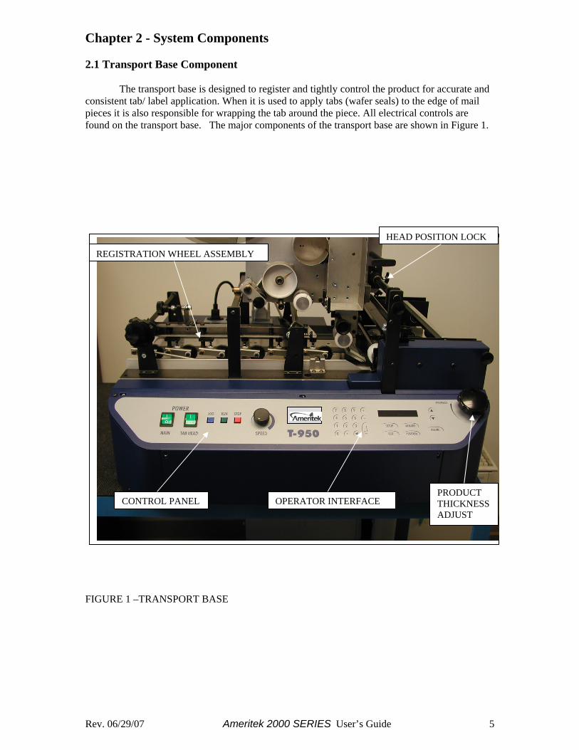
Chapter 2 - System Components 2.1 Transport Base Component The transport base is designed to register and tightly control the product for accurate and consistent tab/ label application. When it is used to apply tabs (wafer seals) to the edge of mail pieces it is also responsible for wrapping the tab around the piece. All electrical controls are found on the transport base. The major components of the transport base are shown in Figure 1.
FIGURE 1 –TRANSPORT BASE
REGISTRATION WHEEL ASSEMBLY
CONTROL PANEL PRODUCT THICKNESS ADJUST
HEAD POSITION LOCK
OPERATOR INTERFACE
Rev. 06/29/07 Ameritek 2000 SERIES User’s Guide 6
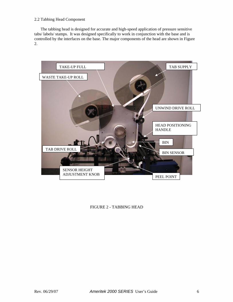
2.2 Tabbing Head Component The tabbing head is designed for accurate and high-speed application of pressure sensitive tabs/ labels/ stamps. It was designed specifically to work in conjunction with the base and is controlled by the interfaces on the base. The major components of the head are shown in Figure 2.
FIGURE 2 - TABBING HEAD
TAB DRIVE ROLL
SENSOR HEIGHT ADJUSTMENT KNOB
TAKE-UP FULL
PEEL POINT
WASTE TAKE-UP ROLL
BIN SENSOR
BIN
UNWIND DRIVE ROLL
HEAD POSITIONING HANDLE
TAB SUPPLY

Rev. 06/29/07 Ameritek 2000 SERIES User’s Guide 7
Chapter 3 - Electronic Controls 3.1 Transport Control Panel The Transport Control Panel is located on the left side of the base front. This panel controls system power and transport base motor condition. Housed on this panel are the following six controls:
• Main Power Rocker Switch • Tab Head Power Rocker Switch • Jog Push Button Switch • Run Push Button Switch • Stop Push Button Switch • Transport Speed Potentiometer
3.1.1 Main Power Rocker Switch This switch controls power to the tabber base. This switch must be on and lit in order for the transport base to function. 3.1.2 Tab Head Power Rocker Switch This switch controls power to the tabbing head. This switch must be on and lit in order for the tabbing head to function. Since this switch obtains its power from the base, the Main Power Rocker Switch must also be on. 3.1.3 Jog Push Button Switch This switch is provided to aid operator setup. When depressed the transport base motor will run at the speed set by the speed control pot. The base will stop as soon as the switch is released. 3.1.4 Run Push Button Switch This switch is used to start the transport base motor. The transport base motor will run at the speed set by the speed control until the Stop Switch is depressed or the electronic controls stop the unit. 3.1.5 Stop Push Button Switch When depressed, this switch stops the transport base motor. 3.1.6 Transport Speed Potentiometer The transport speed potentiometer is used to control the speed of the base. Turning this knob clockwise will increase base speed.
Rev. 06/29/07 Ameritek 2000 SERIES User’s Guide 8
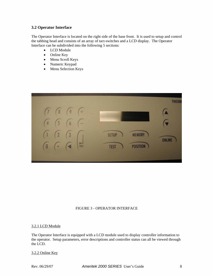
3.2 Operator Interface The Operator Interface is located on the right side of the base front. It is used to setup and control the tabbing head and consists of an array of tact-switches and a LCD display. The Operator Interface can be subdivided into the following 5 sections:
• LCD Module • Online Key • Menu Scroll Keys • Numeric Keypad • Menu Selection Keys
FIGURE 3 - OPERATOR INTERFACE
3.2.1 LCD Module The Operator Interface is equipped with a LCD module used to display controller information to the operator. Setup parameters, error descriptions and controller status can all be viewed through the LCD. 3.2.2 Online Key
Rev. 06/29/07 Ameritek 2000 SERIES User’s Guide 9
This key toggles the head condition between online and offline. When the tabber is offline the head will not dispense any tabs/ labels. The head must be offline to access setup parameters within the controller. The head must be online in order to dispense tabs/ labels. Online/ Offline condition is displayed on the LCD. While online the second line of the LCD displays “NORMAL STATUS”, if offline the first line of the LCD displays “OFFLINE”. 3.2.3 Menu Scroll Keys The (up arrow) and (down arrow) keys are used to scroll up and down menus to facilitate menu item selection when used during setup. These keys are also used to control the display of production data when the unit is online. The operator can choose between the following three different production displays: • Product Count • Transport Speed • Production Rate
3.2.3.1 Product Count The controller maintains a six-digit product count. The operator through use of the setup key can reset this counter. An example of a typical count display follows. FORMS DONE: 000123 NORMAL STATUS 3.2.3.2 Transport Speed The controller must be aware of the transport speed to accurately locate tabs/ labels on the product. This speed, displayed in feet/ minute, represents the approximate belt speed of the base. An example of a typical speed display follows. SPEED: 160 FT/M NORMAL STATUS 3.2.3.3 Production Rate Another useful production item is the production rate. The controller can display the approximate real-time production rate of the tabber. Production rate is displayed as product #/ hour. An example of a typical rate display follows. PROD RATE: 14000 PPH NORMAL STATUS 3.2.4 Numeric Keypad A numeric keypad is provided to allow direct entry of settings from the Operator Interface. This keypad is functional for tabber setup only when the unit is offline. 3.2.5 Menu Selection Keys Beneath the LCD are four menu selector keys. These keys are used to access the different setup and test menus. The four keys are listed below: • Test • Position • Setup • Memory
Rev. 06/29/07 Ameritek 2000 SERIES User’s Guide 10
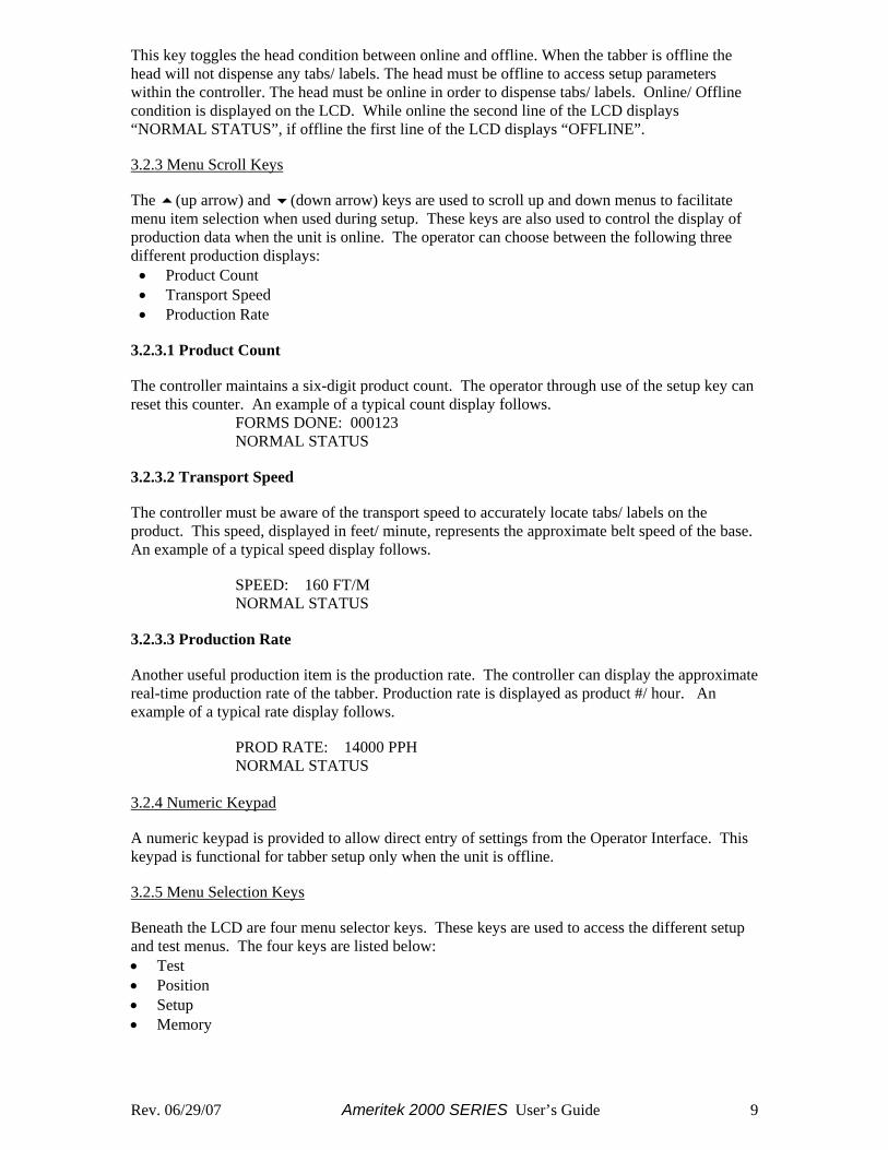
Chapter 4 – System Setup 4.1 Base Set-up 4.1.1 Attach Bridge There is a 3 inch bridge that needs to be attached to the input of the tabber (See Figure 4). Requirement: The bridge is need for proper transition of the piece form the feeder to the tabber. Procedure:
1. Attach screws to mount bridge as shown in Figures 4 & 5. 2. The top of the bridge should be slightly higher than the top of the transport belt.
Figure 4
Figure 5
STRAP ASSEMBLY
BRIDGE
PRODUCT GUIDE
SCREWS
SCREWS
Rev. 06/29/07 Ameritek 2000 SERIES User’s Guide 11
4.1.2 Feeder/ Inkjet Height When this system is used “Inline” with other equipment, it is important for the paper path to be flat. Use some kind of stand or spacer to obtain a flat paper path. The correct height must be set so there is a smooth transition of the mail piece from the feeding equipment to the tabber. 4.1.3 Position Base The Feeder/Inkjet must be placed on a table or stand so that it is aligned with the input and output of the Tabber Base. Requirement: Position Feeder/ Inkjet Base next to Tabber for product transition. Procedure
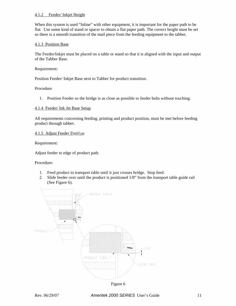
1. Position Feeder so the bridge is as close as possible to feeder belts without touching. 4.1.4 Feeder/ Ink Jet Base Setup All requirements concerning feeding, printing and product position, must be met before feeding product through tabber. 4.1.5 Adjust Feeder Position Requirement: Adjust feeder to edge of product path. Procedure:
1. Feed product to transport table until it just crosses bridge. Stop feed. 2. Slide feeder over until the product is positioned 1/8” from the transport table guide rail
(See Figure 6).
Figure 6
Rev. 06/29/07 Ameritek 2000 SERIES User’s Guide 12
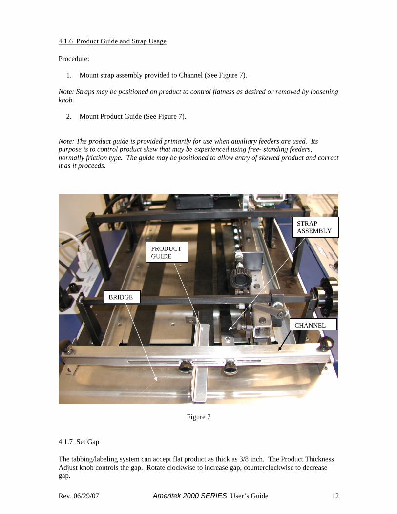
4.1.6 Product Guide and Strap Usage Procedure:
1. Mount strap assembly provided to Channel (See Figure 7). Note: Straps may be positioned on product to control flatness as desired or removed by loosening knob.
2. Mount Product Guide (See Figure 7). Note: The product guide is provided primarily for use when auxiliary feeders are used. Its purpose is to control product skew that may be experienced using free- standing feeders, normally friction type. The guide may be positioned to allow entry of skewed product and correct it as it proceeds.
Figure 7
4.1.7 Set Gap The tabbing/labeling system can accept flat product as thick as 3/8 inch. The Product Thickness Adjust knob controls the gap. Rotate clockwise to increase gap, counterclockwise to decrease gap.
STRAP ASSEMBLY
BRIDGE
PRODUCTGUIDE
CHANNEL
Rev. 06/29/07 Ameritek 2000 SERIES User’s Guide 13
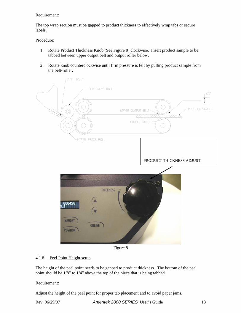
Requirement: The top wrap section must be gapped to product thickness to effectively wrap tabs or secure labels. Procedure:
1. Rotate Product Thickness Knob (See Figure 8) clockwise. Insert product sample to be tabbed between upper output belt and output roller below.
2. Rotate knob counterclockwise until firm pressure is felt by pulling product sample from
the belt-roller.
Figure 8
4.1.8 Peel Point Height setup The height of the peel point needs to be gapped to product thickness. The bottom of the peel point should be 1/8” to 1/4” above the top of the piece that is being tabbed. Requirement: Adjust the height of the peel point for proper tab placement and to avoid paper jams.
PRODUCT THICKNESS ADJUST
Rev. 06/29/07 Ameritek 2000 SERIES User’s Guide 14
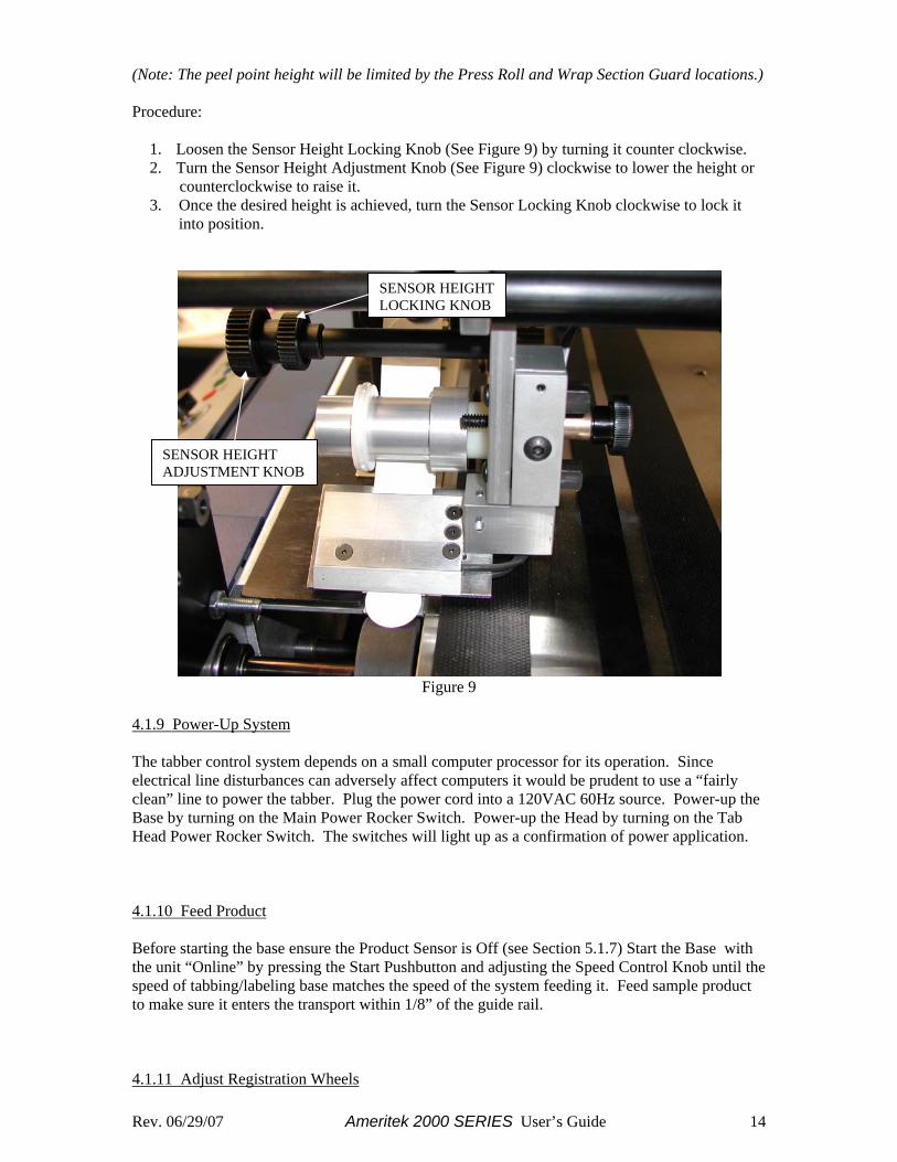
(Note: The peel point height will be limited by the Press Roll and Wrap Section Guard locations.) Procedure:
1. Loosen the Sensor Height Locking Knob (See Figure 9) by turning it counter clockwise. 2. Turn the Sensor Height Adjustment Knob (See Figure 9) clockwise to lower the height or
counterclockwise to raise it. 3. Once the desired height is achieved, turn the Sensor Locking Knob clockwise to lock it
into position.
Figure 9
4.1.9 Power-Up System The tabber control system depends on a small computer processor for its operation. Since electrical line disturbances can adversely affect computers it would be prudent to use a “fairly clean” line to power the tabber. Plug the power cord into a 120VAC 60Hz source. Power-up the Base by turning on the Main Power Rocker Switch. Power-up the Head by turning on the Tab Head Power Rocker Switch. The switches will light up as a confirmation of power application. 4.1.10 Feed Product Before starting the base ensure the Product Sensor is Off (see Section 5.1.7) Start the Base with the unit “Online” by pressing the Start Pushbutton and adjusting the Speed Control Knob until the speed of tabbing/labeling base matches the speed of the system feeding it. Feed sample product to make sure it enters the transport within 1/8” of the guide rail. 4.1.11 Adjust Registration Wheels
SENSOR HEIGHT ADJUSTMENT KNOB
SENSOR HEIGHT LOCKING KNOB
Rev. 06/29/07 Ameritek 2000 SERIES User’s Guide 15
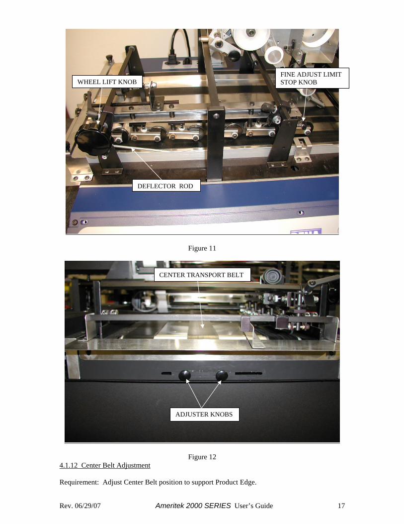
The tabbing/labeling base uses a set of registration wheels to ensure consistent placement and wrap of tabs and labels. The wheels are used to “push” the product against the guide rail guide and secure the product to the transport belt. The first three entry wheels are slaved together on a swivel system that allows angle adjustment to drive the product against the guide rail for registration. The following three drive wheels are fixed in a straight line to maintain registration along the guide rail for accurate tab/label placement on the product. The registration wheel assembly may be positioned over any portion of the lower transport belts along the square mounting shafts, by loosening lever locks and sliding to desired location. Drive pressure may be increased or decreased by rotating the Wheel Lift Knob. This knob is also used to lift the complete assembly off the lower transport belts for repositioning. The Registration Wheel Assembly functions best when product is delivered 1/8” or less from the guide rail at the entry point. (See Figure 5 of Section 4.1.5). Warning: Product feeding and registration must be properly adjusted before tabbing! Turn tab head power off and move the head aside. Visually check feeding and registration with sample product. Any skew or catch points must be eliminated. A Product Guide and Hold Down Strap are provided to control the conditions above (See Section 4.1.6)) at the input end of tabber. The primary feeder, free standing friction type, ink jet base friction or vacuum, must also be properly adjusted to eliminate double feeds, product skew or side to side drift. Requirement: Registration wheels must be positioned and adjusted to consistently guide product edge along guide rail, without distorting or causing product stall. Note: A fine adjustment limit stop (See Figure 11) is provided to control and maintain drive pressure. Turning the knob clockwise limits the down-drive pressure. Turning the knob counterclockwise allows more down-drive pressure to be set. The limit stop allows the assembly to be raised completely from a preset drive position and returned to that position without adjustments. Procedure:
1. Loosen lever locks (See Figure 10). Position registration wheel assembly over belt adjacent to guide rail.
2. Adjust angle drive wheel knob to angle three slaved wheels towards guide rail (See Figure
10). Do not adjust wheels to maximum angle. Use minimum angle, increase only as necessary.
Note: Occasionally it may be necessary to angle the entire registration system. (See Figure 10) to assure product remains against guide rail. The lever lock mounting assemblies permit a limited amount of misalignment for this purpose. Caution: Over adjustment of angle wheels and excessive drive pressure can cause product to ride up guide rail, or cause product to distort or stall. A Deflector Rod (See Figure 11) is provided along the guide rail to help hold down product.
3. Turn main power on and operate base with speed control at slow speed. Rotate drive wheel lift knob (See Figure 11) counterclockwise until all drive wheels are turning. Turn fine adjustment knob screw clockwise to meet stop on square shaft (See Figure 11).
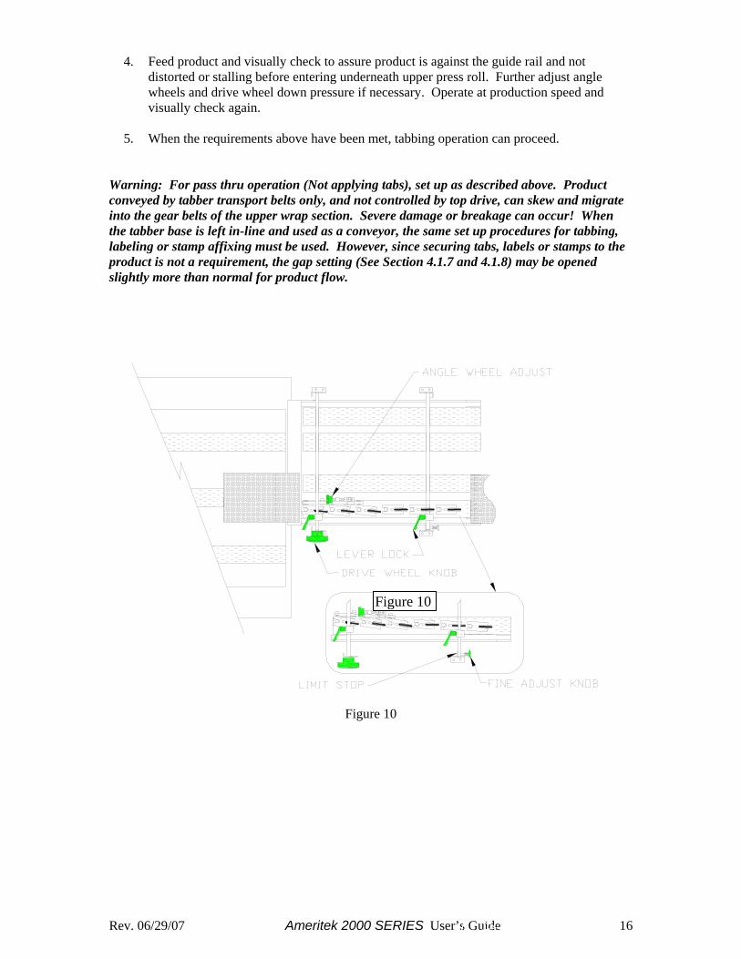
Rev. 06/29/07 Ameritek 2000 SERIES User’s Guide 16
4. Feed product and visually check to assure product is against the guide rail and not
distorted or stalling before entering underneath upper press roll. Further adjust angle wheels and drive wheel down pressure if necessary. Operate at production speed and visually check again.
5. When the requirements above have been met, tabbing operation can proceed.
Warning: For pass thru operation (Not applying tabs), set up as described above. Product conveyed by tabber transport belts only, and not controlled by top drive, can skew and migrate into the gear belts of the upper wrap section. Severe damage or breakage can occur! When the tabber base is left in-line and used as a conveyor, the same set up procedures for tabbing, labeling or stamp affixing must be used. However, since securing tabs, labels or stamps to the product is not a requirement, the gap setting (See Section 4.1.7 and 4.1.8) may be opened slightly more than normal for product flow.
Figure 10
Figure 10
Rev. 06/29/07 Ameritek 2000 SERIES User’s Guide 17
Figure 11
Figure 12 4.1.12 Center Belt Adjustment Requirement: Adjust Center Belt position to support Product Edge.
WHEEL LIFT KNOB
DEFLECTOR ROD
FINE ADJUST LIMIT STOP KNOB
CENTER TRANSPORT BELT
ADJUSTER KNOBS
Rev. 06/29/07 Ameritek 2000 SERIES User’s Guide 18
Note: Transport Base must be powered up to move center belt. Procedure:
1. Power up Base and operate with Speed Control. 2. Loosen Adjuster Knobs shown in Figure 12. 3. Gently push Adjuster along its slot to position Center Belt as required. 4. Secure Knobs to maintain belt position.
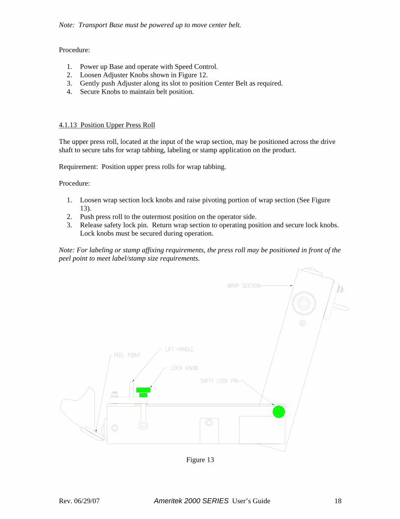
4.1.13 Position Upper Press Roll The upper press roll, located at the input of the wrap section, may be positioned across the drive shaft to secure tabs for wrap tabbing, labeling or stamp application on the product. Requirement: Position upper press rolls for wrap tabbing. Procedure:
1. Loosen wrap section lock knobs and raise pivoting portion of wrap section (See Figure 13).
2. Push press roll to the outermost position on the operator side. 3. Release safety lock pin. Return wrap section to operating position and secure lock knobs.
Lock knobs must be secured during operation. Note: For labeling or stamp affixing requirements, the press roll may be positioned in front of the peel point to meet label/stamp size requirements.
Figure 13
Rev. 06/29/07 Ameritek 2000 SERIES User’s Guide 19
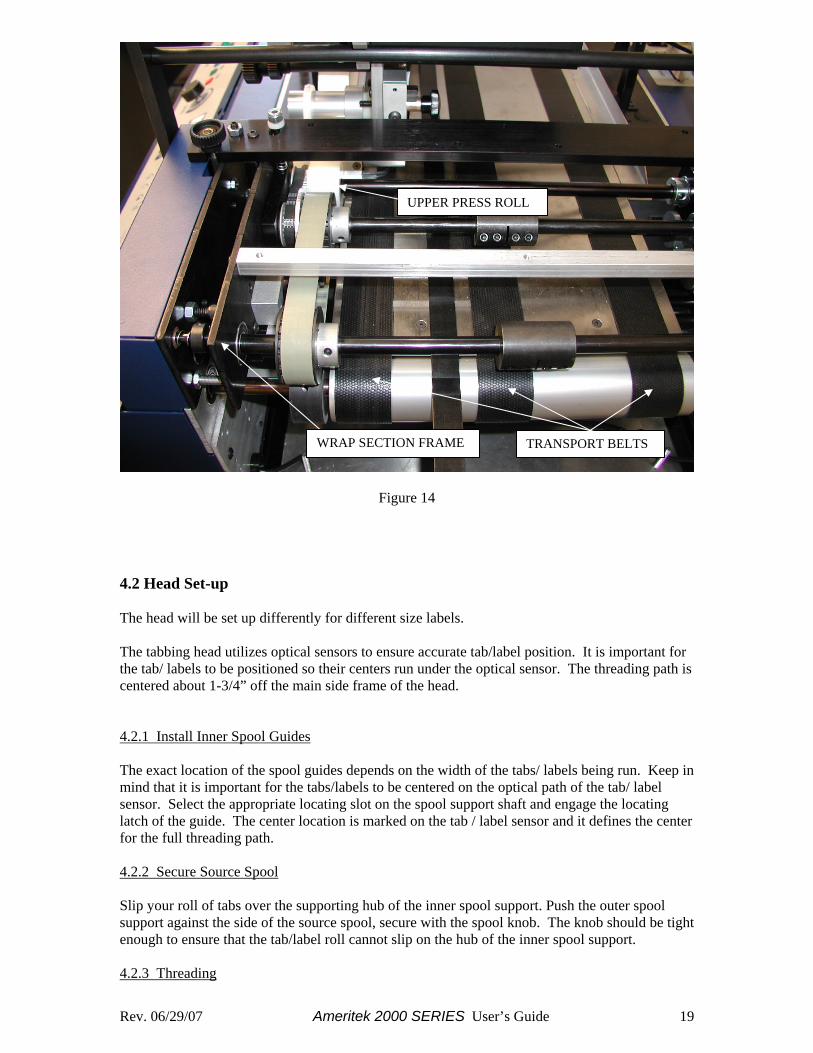
Figure 14 4.2 Head Set-up The head will be set up differently for different size labels. The tabbing head utilizes optical sensors to ensure accurate tab/label position. It is important for the tab/ labels to be positioned so their centers run under the optical sensor. The threading path is centered about 1-3/4” off the main side frame of the head. 4.2.1 Install Inner Spool Guides The exact location of the spool guides depends on the width of the tabs/ labels being run. Keep in mind that it is important for the tabs/labels to be centered on the optical path of the tab/ label sensor. Select the appropriate locating slot on the spool support shaft and engage the locating latch of the guide. The center location is marked on the tab / label sensor and it defines the center for the full threading path. 4.2.2 Secure Source Spool Slip your roll of tabs over the supporting hub of the inner spool support. Push the outer spool support against the side of the source spool, secure with the spool knob. The knob should be tight enough to ensure that the tab/label roll cannot slip on the hub of the inner spool support. 4.2.3 Threading
UPPER PRESS ROLL
TRANSPORT BELTS WRAP SECTION FRAME
Rev. 06/29/07 Ameritek 2000 SERIES User’s Guide 20
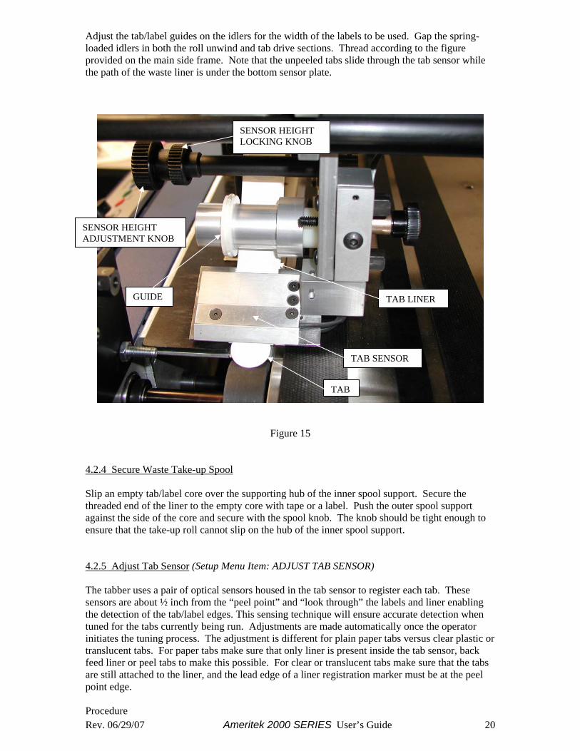
Adjust the tab/label guides on the idlers for the width of the labels to be used. Gap the spring-loaded idlers in both the roll unwind and tab drive sections. Thread according to the figure provided on the main side frame. Note that the unpeeled tabs slide through the tab sensor while the path of the waste liner is under the bottom sensor plate.
Figure 15
4.2.4 Secure Waste Take-up Spool Slip an empty tab/label core over the supporting hub of the inner spool support. Secure the threaded end of the liner to the empty core with tape or a label. Push the outer spool support against the side of the core and secure with the spool knob. The knob should be tight enough to ensure that the take-up roll cannot slip on the hub of the inner spool support. 4.2.5 Adjust Tab Sensor (Setup Menu Item: ADJUST TAB SENSOR) The tabber uses a pair of optical sensors housed in the tab sensor to register each tab. These sensors are about ½ inch from the “peel point” and “look through” the labels and liner enabling the detection of the tab/label edges. This sensing technique will ensure accurate detection when tuned for the tabs currently being run. Adjustments are made automatically once the operator initiates the tuning process. The adjustment is different for plain paper tabs versus clear plastic or translucent tabs. For paper tabs make sure that only liner is present inside the tab sensor, back feed liner or peel tabs to make this possible. For clear or translucent tabs make sure that the tabs are still attached to the liner, and the lead edge of a liner registration marker must be at the peel point edge. Procedure
TAB
SENSOR HEIGHT ADJUSTMENT KNOB
TAB SENSOR
GUIDE TAB LINER
SENSOR HEIGHT LOCKING KNOB

Rev. 06/29/07 Ameritek 2000 SERIES User’s Guide 21
1) Power-up the head by turning on the Tab Head Power Rocker Switch 2) Press the “SETUP” key to access the setup menu. “SETUP” should be displayed on the first
line of the display. 3) Press either the “ ” or “ ” until “ADJUST TAB SENSOR ?” is displayed on the second
line of the LCD. 4) When using typical paper tabs it is important to have the machine fully threaded, but with no
tab present in the tab sensor. It is important to make this setting while only liner is present in the tab sensor. When using translucent or clear tabs it is important to have the machine fully threaded with a tab present in the tab sensor. It is important not to have a liner registration mark directly under the sensor while making the adjustment. Since the optical path of the tab sensor is approximately ½” from the peel point edge, adjusting the sensor after aligning a registration mark with the peel point edge will assure that proper setting will be found.
5) The controller will automatically make the optimal sensor adjustment when the “ENTER” key is pressed. The LCD will indicate completion by displaying “TAB SENSOR ADJUSTED”.
“SETTING = xxx% “ The xxx represents the electrical setting used for the sensor. This value should normally range from 85% to 97% when setting with liner in the sensor. A value of 01% indicates sensor disconnection or sensor failure. A value between 01% and 85% probably indicates that the tab sensor requires cleaning or is damaged/aged. A value of 100% should always be obtained when adjusted with no liner present. A value of less than 100% with no liner would indicate a dirty sensor. The sensor should be adjusted without liner only as a diagnostic tool. The sensor must be readjusted with liner before normal operation. 4.2.6 Adjust Pitch Setting (Setup Menu Item: PITCH) The distance between the lead edges of two consecutive tabs still attached to release liner defines the Tab Pitch. This is an important value since it defines how far the tab drive will move when it applies tabs. The minimum pitch is 0.75” and the maximum pitch is 7.00”. Note: Since it is difficult for the system to reverse itself, it is always better to enter a lower number for pitch versus a larger number. The system can “self-correct” for any slightly undersized pitch whereas a system with an oversized pitch may never be able to synchronize the tab position. It short, an oversized pitch means bad tab/label placement. Procedure 1) Take the system offline. 2) Press the “SETUP” key to access the setup menu. “SETUP” should be displayed on the first
line of the display. 3) Press either the “ ” or “ ” until “PITCH: x.xx >_” is displayed on the second line of the
display. The x.xx represents the current setting for tab pitch. 4) To increase the Tab Pitch, press the “+” key until the desired location is displayed as the
current setting. To decrease the Tab Pitch, press the “-“ key until the desired location is displayed as the current setting.
-Or- 5) The desired pitch can be directly entered from the numeric keypad. 6) As the new setting is entered it appears to the right of the current setting. 7) Once entry of the new value is completed press the “ENTER” key to save the new value. The
LCD will indicate completion by replacing the current setting with the new setting.
Rev. 06/29/07 Ameritek 2000 SERIES User’s Guide 22
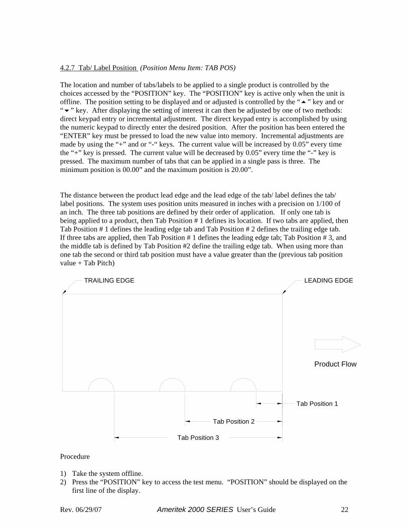
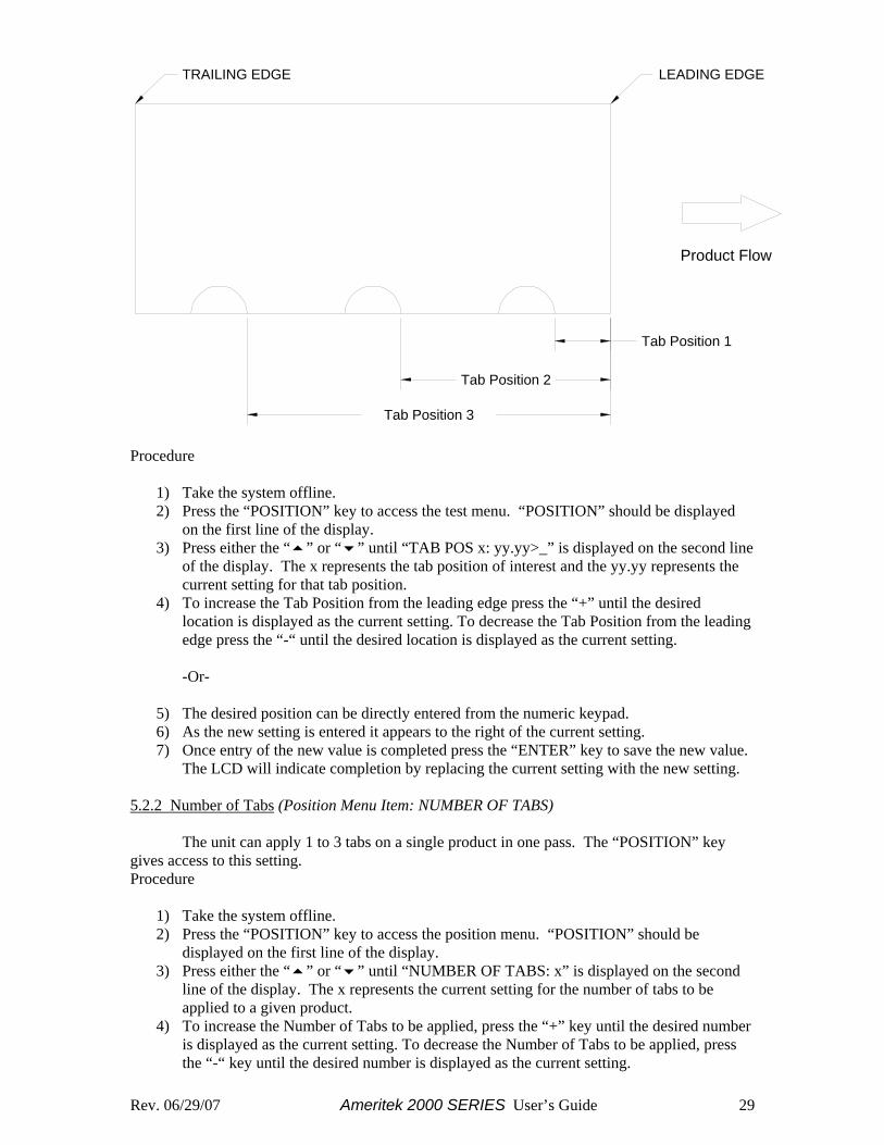
4.2.7 Tab/ Label Position (Position Menu Item: TAB POS) The location and number of tabs/labels to be applied to a single product is controlled by the choices accessed by the “POSITION” key. The “POSITION” key is active only when the unit is offline. The position setting to be displayed and or adjusted is controlled by the “ ” key and or “ ” key. After displaying the setting of interest it can then be adjusted by one of two methods: direct keypad entry or incremental adjustment. The direct keypad entry is accomplished by using the numeric keypad to directly enter the desired position. After the position has been entered the “ENTER” key must be pressed to load the new value into memory. Incremental adjustments are made by using the “+” and or “-“ keys. The current value will be increased by 0.05” every time the “+” key is pressed. The current value will be decreased by 0.05” every time the “-” key is pressed. The maximum number of tabs that can be applied in a single pass is three. The minimum position is 00.00” and the maximum position is 20.00”. The distance between the product lead edge and the lead edge of the tab/ label defines the tab/ label positions. The system uses position units measured in inches with a precision on 1/100 of an inch. The three tab positions are defined by their order of application. If only one tab is being applied to a product, then Tab Position # 1 defines its location. If two tabs are applied, then Tab Position # 1 defines the leading edge tab and Tab Position # 2 defines the trailing edge tab. If three tabs are applied, then Tab Position # 1 defines the leading edge tab; Tab Position # 3, and the middle tab is defined by Tab Position #2 define the trailing edge tab. When using more than one tab the second or third tab position must have a value greater than the (previous tab position value + Tab Pitch)
Tab Position 2
Tab Position 3
Tab Position 1
Product Flow
LEADING EDGETRAILING EDGE
Procedure 1) Take the system offline. 2) Press the “POSITION” key to access the test menu. “POSITION” should be displayed on the
first line of the display.
Rev. 06/29/07 Ameritek 2000 SERIES User’s Guide 23
3) Press either the “ ” or “ ” until “TAB POS x: yy.yy>_” is displayed on the second line of the display. The x represents the tab position of interest and the yy.yy represents the current setting for that tab position.
4) To increase the Tab Position from the leading edge press the “+” until the desired location is displayed as the current setting. To decrease the Tab Position from the leading edge press the “-“ until the desired location is displayed as the current setting.
-Or- 5) The desired position can be directly entered from the numeric keypad. 6) As the new setting is entered it appears to the right of the current setting. 7) Once entry of the new value is completed press the “ENTER” key to save the new value. The
LCD will indicate completion by replacing the current setting with the new setting. 4.2.8 Number of Tabs (Position Menu Item: NUMBER OF TABS) The unit can apply 1 to 3 tabs on a single product in one pass. The “POSITION” key gives access to this setting. Procedure 1) Take the system offline. 2) Press the “POSITION” key to access the position menu. “POSITION” should be displayed
on the first line of the display. 3) Press either the “ ” or “ ” until “NUMBER OF TABS: x” is displayed on the second line
of the display. The x represents the current setting for the number of tabs to be applied to a given product.
4) To increase the Number of Tabs to be applied, press the “+” key until the desired number is displayed as the current setting. To decrease the Number of Tabs to be applied, press the “-“ key until the desired number is displayed as the current setting.
4.2.9 Begin Tabbing The system should now be ready to apply tabs/labels. Turn the head online by pressing the online key on the operator interface.
Rev. 06/29/07 Ameritek 2000 SERIES User’s Guide 24
Chapter 5 - Controller Programming/Diagnostics 5.1 Setup Programming The operator can adjust many of the components and parameters necessary to setup the unit, through the operator interface. The “SETUP” key is used to access these adjustments and is active only when the unit is offline. The setup parameter to be displayed and or adjusted is controlled by the “ ” key and or “ ” key. The components/ parameters that can be adjusted are listed below: • Tab Pitch • Job Memory • Auto Tab Calculator Product Size • Product/ Tab Sensor Offset • Tab Sensor Sensitivity • Counter Reset • Product Sensor Enable 5.1.1 Pitch Setting (Setup Menu Item: PITCH) The distance between the lead edges of two consecutive tabs still attached to release liner defines the Tab Pitch. This is an important value since it defines how far the tab drive will move when it applies tabs. The minimum pitch is 0.75” and the maximum pitch is 2.00”. Procedure
1) Take the system offline. 2) Press the “SETUP” key to access the setup menu. “SETUP” should be displayed on the
first line of the display. 3) Press either the “ ” or “ ” until “PITCH: x.xx >_” is displayed on the second line of
the display. The x.xx represents the current setting for tab pitch. 4) To increase the Tab Pitch, press the “+” key until the desired location is displayed as the
current setting. To decrease the Tab Pitch, press the “-“ key until the desired location is displayed as the current setting.
-Or-
5) The desired pitch can be directly entered from the numeric keypad. 6) As the new setting is entered it appears to the right of the current setting. 7) Once entry of the new value is completed press the “ENTER” key to save the new value.
The LCD will indicate completion by replacing the current setting with the new setting. 5.1.2 Save Setup to Memory (Setup Menu Item: SAVE(M1 or M2)

Rev. 06/29/07 Ameritek 2000 SERIES User’s Guide 25
Two memory locations are reserved for saving the most frequent job settings. Memory location 1 can retain the Tab Pitch, Tab Position # 1, Tab Position # 2, Tab Position # 3 and Number of Tabs settings. Memory location 2 can retain the Tab Pitch, Tab Position # 1, Tab Position # 2, and Number of Tabs settings. Procedure 1) Take the system offline. 2) Press the “SETUP” key to access the setup menu. “SETUP” should be displayed on the first
line of the display. 3) Press either the “ ” or “ ” until “SAVE(M1 or M2) >_” is displayed on the second line of
the display. 4) To save the current settings enter either “1” or “2” from the numeric keypad, then press the
“ENTER” key. 5) The LCD will display the message “Mx SAVED”. The x represents the number of the
memory location selected by the operator. 5.1.3 Auto Tab Calculator Product Size (Setup Menu Item: AUTO) The controller can calculate the proper location(s) for tabs on any given mail piece. The operator must enter the size of the mail piece (product), the number of tabs to be applied, and the tab pitch. The system can then calculate and program the appropriate tab positions. The minimum product size is 05.00” and the maximum is 20.00”. Procedure 1) Take the system offline. 2) Press the “SETUP” key to access the setup menu. “SETUP” should be displayed on the first
line of the display. 3) Press either the “ ” or “ ” until “AUTO: xx.xx >_” is displayed on the second line of the
LCD. The xx.xx represents the current product size to be used by the calculator. 4) Increase the product size by pressing the “+” key until the desired size is displayed as the
current setting. Decrease the product size by pressing the “-“ key until the desired size is displayed as the current setting.
-Or- 5) The desired size can be directly entered from the numeric keypad. As the new setting is
entered it appears to the right of the current setting. 6) Once entry of the new value is completed press the “ENTER” key to calculate the new
position values. The LCD will indicate completion by displaying the newly calculated positions “TAB 1 TAB 2 TAB 3”
xx.xx yy.yy zz.zz 5.1.4 Product/ Tab Sensor Offset (Setup Menu Item: SENSOR)

Rev. 06/29/07 Ameritek 2000 SERIES User’s Guide 26
The controller must know the distance between the product sensor and tab sensor (peel point) in order to accurately place tabs at the desired location. When the operator makes small mechanical adjustments of the tab sensor location, the distance between the product and tab sensors will also be changed. This programmed offset must be kept up to date with sensor movements, in order to obtain the highest positional accuracy. Although the minimum offset is 2.00” and the maximum is 9.00”, only small changes to the default offset should be needed. Procedure 1) Take the system offline. 2) Press the “SETUP” key to access the setup menu. “SETUP” should be displayed on the first
line of the display. 3) Press either the “ ” or “ ” until “SENSOR: x.xx >_” is displayed on the second line of the
LCD. The x.xx represents the current setting for sensor offset. 4) To increase the Sensor Offset, press the “+” key until the desired value is displayed as the
current setting. To decrease the Sensor Offset, press the “-“ key until the desired value is displayed as the current setting.
-Or- 5) The desired offset can be directly entered from the numeric keypad. 6) As the new setting is entered it appears to the right of the current setting. 7) Once entry of the new value is completed press the “ENTER” key to save the new value. The
LCD will indicate completion by replacing the current setting with the new setting. 5.1.5 Tab Sensor Sensitivity (Setup Menu Item: ADJUST TAB SENSOR) The controller must know the location of each tab edge in order to place the tab accurately on product. Through beam type opto-electronic sensors are used to “look through” the liner and tabs. The electronics can detect a significant contrast between just liner (found between tabs) and the combination of tabs on top of the release liner. Since this accurate detection is so

Rev. 06/29/07 Ameritek 2000 SERIES User’s Guide 27
important, setting the correct setting has been made very simple. This adjustment should be made periodically since dust and debris can block the optical path, thus affecting operation. It is also important to make the adjustment whenever setting up for a different type/ manufacturer of tab. Procedure
1) Take the system offline. 2) Press the “SETUP” key to access the setup menu. “SETUP” should be displayed on the
first line of the display. 3) Press either the “ ” or “ ” until “ADJUST TAB SENSOR ?” is displayed on the
second line of the LCD. 4) When using typical paper tabs it is important to have the machine fully threaded, but with
no tab present in the tab sensor. It is important to make this setting while only liner is present in the tab sensor. When using translucent or clear tabs it is important to have the machine fully threaded with a tab present in the tab sensor. It is important not to have a liner registration mark directly under the sensor while making the adjustment. Since the optical path of the tab sensor is approximately ½” from the peel point edge, adjusting the sensor after aligning a registration mark with the peel point edge will assure that proper setting will be found.
5) The controller will automatically make the optimal sensor adjustment when the “ENTER” key is pressed. The LCD will indicate completion by displaying :
“TAB SENSOR ADJUSTED”. “SETTING = xxx% “ The xxx represents the electrical setting used for the sensor. This value should normally range from 85% to 97% when setting with liner in the sensor. A value of 01% indicates sensor disconnection or sensor failure. A value between 01% and 85% probably indicates that the tab sensor requires cleaning or is damaged/aged. A value of 100% should always be obtained when adjusted with no liner present. A value of less than 100% with no liner would indicate a dirty sensor. The sensor should be adjusted without liner only as a diagnostic tool. The sensor must be readjusted with liner before normal operation. 5.1.6 Counter Reset (Setup Menu Item: RESET COUNT ?) The controller displays and records a product count. The operator can reset this count to zero at any time. The current count is retained in memory at power down and recalled at power up. Procedure 1) Take the system offline. 2) Press the “SETUP” key to access the setup menu. “SETUP” should be displayed on the first
line of the display. 3) Press either the “ ” or “ ” until “RESET COUNT ? xxxxxx” is displayed on the second
line of the display. The xxxxxx represent the current count. 4) Press the “ENTER” key to reset the counter. The LCD will be updated upon reset and now
display “RESET COUNT ? 000000”. 5.1.7 Product Sensor Selection (Setup Menu Item: PRODUCT SENSOR) Through beam type opto-electronic sensors are used to detect the presence of product to be tabbed/ labeled. The operator can enable or diable the Product Sensor. It is recommended to run the Base with the Product Sensor turned off while setting up the aligment and registration of the product within the Base. Procedure

Rev. 06/29/07 Ameritek 2000 SERIES User’s Guide 28
1) Take the system offline. 2) Press the “SETUP” key to access the setup menu. “SETUP” should be displayed on the
first line of the display. 3) Press either the “ ” or “ ” until “PRODUCT SENSOR: ON or OFF” is displayed on
the second line of the LCD. 4) Press the “+” key to change from OFF to ON. Press the “-“ key to change from ON to
OFF. The LCD will update sensor selection as it is made. 5.2 Position Programming The location and number of tabs/labels to be applied to a single product is controlled by the choices accessed by the “POSITION” key. The “POSITION” key is active only when the unit is offline. The position setting to be displayed and or adjusted is controlled by the “ ” key and or “ ” key. After displaying the setting of interest it can then be adjusted by one of two methods: direct keypad entry or incremental adjustment. The direct keypad entry is accomplished by using the numeric keypad to directly enter the desired position. After the position has been entered the “ENTER” key must be pressed to load the new value into memory. Incremental adjustments are made by using the “+” and or “-“ keys. The current value will be increased by 0.05” every time the “+” key is pressed. The current value will be decreased by 0.05” every time the “-” key is pressed. The maximum number of tabs that can be applied in a single pass is three. The minimum position is 00.00” and the maximum position is 20.00”. 5.2.1 Tab/ Label Position Entry (Position Menu Item: TAB POS) The distance between the product lead edge and the lead edge of the tab/ label defines the tab/ label positions. The system uses position units measured in inches with a precision on 1/100 of an inch. The three tab positions are defined by their order of application. If only one tab is being applied to a product, then Tab Position # 1 defines its location. If two tabs are applied, then Tab Position # 1 defines the leading edge tab and Tab Position # 2 defines the trailing edge tab. If three tabs are applied, then Tab Position # 1 defines the leading edge tab; Tab Position # 3 defines the trailing edge tab, and the middle tab is defined by Tab Position #2. When using more than one tab the second or third tab position must have a value greater than the (previous tab position value + Tab Pitch).
Rev. 06/29/07 Ameritek 2000 SERIES User’s Guide 29
Tab Position 2
Tab Position 3
Tab Position 1
Product Flow
LEADING EDGETRAILING EDGE
Procedure
1) Take the system offline. 2) Press the “POSITION” key to access the test menu. “POSITION” should be displayed
on the first line of the display. 3) Press either the “ ” or “ ” until “TAB POS x: yy.yy>_” is displayed on the second line
of the display. The x represents the tab position of interest and the yy.yy represents the current setting for that tab position.
4) To increase the Tab Position from the leading edge press the “+” until the desired location is displayed as the current setting. To decrease the Tab Position from the leading edge press the “-“ until the desired location is displayed as the current setting.
-Or-
5) The desired position can be directly entered from the numeric keypad. 6) As the new setting is entered it appears to the right of the current setting. 7) Once entry of the new value is completed press the “ENTER” key to save the new value.
The LCD will indicate completion by replacing the current setting with the new setting. 5.2.2 Number of Tabs (Position Menu Item: NUMBER OF TABS) The unit can apply 1 to 3 tabs on a single product in one pass. The “POSITION” key gives access to this setting. Procedure
1) Take the system offline. 2) Press the “POSITION” key to access the position menu. “POSITION” should be
displayed on the first line of the display. 3) Press either the “ ” or “ ” until “NUMBER OF TABS: x” is displayed on the second
line of the display. The x represents the current setting for the number of tabs to be applied to a given product.
4) To increase the Number of Tabs to be applied, press the “+” key until the desired number is displayed as the current setting. To decrease the Number of Tabs to be applied, press the “-“ key until the desired number is displayed as the current setting.

Rev. 06/29/07 Ameritek 2000 SERIES User’s Guide 30
5.3 Head Diagnostics/ Test The electrical control system of the unit is capable of testing 12 critical components. The operator must select which test is to be performed from the operator interface. The unit must be offline before any tests are run. The components/ parameters that can be tested are listed below: • Software Version • Tab Drive Cycle Test • Stop Relay Test • Motor / Brake Test (Take-up motor/ Unwind drive motor) • Base Cover Switch Test • Head Cover Switch Test • Bin Sensor Test • Take-up Sensor Test • Product Sensor Test • Tab Sensor Test • Encoder Test • Factory Reset 5.3.1 Software Version (Test Menu Item: VERSION) It is often important to know the version of the firmware that is running on a system. The firmware version will often determine the capabilities of the unit. This test will simply display the version number of firmware installed on the unit. Procedure 1) Take the system offline. 2) Press the “TEST” key to access the test menu. “TEST” should be displayed on the first line
of the display. 3) Press either the “ ” or “ ” until “VERSION X.X” is displayed on the second line of the
display. (X.X will be the version number of interest) 5.3.2 Tab Drive Cycle Test (Test Menu Item: TAB DRIVE CYCLE) The Tab Drive Cycle Test is used to test the function of the Tab Drive Motor. The Tab Drive Motor is responsible for the accurate application of the tabs/labels. Procedure 1) Take the system offline. 2) Remove any tabs/ labels from the head before conducting this test. 3) Press the “TEST” key to access the test menu. “TEST” should be displayed on the first line
of the display. 4) Press either the “ ” or “ ” until “TAB DRIVE CYCLE: OFF” is displayed on the second
line of the display. 5) Start the test by pressing the “ENTER” key. 6) While the test is being run the display should read “TAB DRIVE CYCLE: ON” and The Tab
Drive Wheel should alternate between 3 different states. The wheel should run forward at high speed (2 second duration), then stop (2 second duration), then run reverse at high speed (2 second duration), followed again by a stopped state. The cycle will continue repeating until the “ENTER” key is used to stop the test.
Rev. 06/29/07 Ameritek 2000 SERIES User’s Guide 31
5.3.3 Stop Relay Test (Test Menu Item: STOP RELAY) The Stop Relay allows the control system to shutdown the base whenever serious problems have been detected. This test allows the operator to test the function of this relay. (Remember all interlocks must be satisfied before running this test. That includes Head Cover, Base Cover, and External Interlock if used.) Procedure 1) Take the system offline. 2) Press the “TEST” key to access the test menu. “TEST” should be displayed on the first line
of the display. 3) Press either the “ ” or “ ” until “STOP RELAY: OFF” is displayed on the second line of
the display. 4) Run the base by pressing the “START” button. The base should stop if the “ENTER” key is
pressed. After the “ENTER” key is pressed STOP RELAY: ON” will display on the second line of the LCD.
5.3.4 Motor/ Brake Test (Test Menu Item: MOTOR/-BRAKE) Two DC gearmotors are used to: 1) unwind the source spool, 2) take-up the waste liner. The Motor/Brake Test allows the operator to test the fitness of each of these gearmotors. Procedure 1) Take the system offline. 2) Remove any tabs/ labels from the head before conducting this test. 3) Press the “TEST” key to access the test menu. “TEST” should be displayed on the first line
of the display. 4) Press either the “ ” or “ ” until “MOTOR/ -BRAKE: OFF” is displayed on the second line
of the display. 5) Press the “ENTER” key to start the test. The second line of the LCD will display “MOTOR/
-BRAKE: ON”. While this test is being run the take-up motor should run continuously. The unwind motor will run when the bin sensor is not blocked and stop when the bin sensor is blocked.
5.3.5 Base Cover Test (Test Menu Item: BASE COVER) A magnetic switch senses the condition of the base cover. This switch is used, as a safety interlock that prevents the system from operating while the cover is open. The switch condition is displayed while this test is being run. Procedure 1) Take the system offline. 2) Press the “TEST” key to access the test menu. “TEST” should be displayed on the first line
of the display. 3) Press either the “ ” or “ ” until “BASE COVER: OPEN” or “BASE COVER: CLOSED”
is displayed on the second line of the display. 4) The LCD display will indicate the current state of the base cover while this test is being run.

Rev. 06/29/07 Ameritek 2000 SERIES User’s Guide 32
5.3.6 Head Cover Test (Test Menu Item: HEAD COVER) A magnetic switch senses the condition of the head cover. This switch is used, as a safety interlock that prevents the system from operating while the cover is open. The switch condition is displayed while this test is being run. Procedure 5) Take the system offline. 6) Press the “TEST” key to access the test menu. “TEST” should be displayed on the first line
of the display. 7) Press either the “ ” or “ ” until “HEAD COVER: OPEN” or “HEAD COVER: CLOSED”
is displayed on the second line of the display. 8) The LCD display will indicate the current state of the head cover while this test is being run. 5.3.7 Bin Sensor Test (Test Menu Item: BIN SENSOR) A “Through Beam” type opto-electrical sensor is used to determine the state of the tab/label bin. The sensor is used to ensure that some tabs/labels have been unwound from the source spool and are ready for application. The bin condition is displayed while this test is being run. Procedure 1) Take the system offline. 2) Press the “TEST” key to access the test menu. “TEST” should be displayed on the first line
of the display. 3) Press either the “ ” or “ ” until “BIN SENSOR: BLOCKED” or “BIN SENSOR:
UNBLOCKED” is displayed on the second line of the display. 4) The LCD display will indicate the current state of the bin sensor while this test is being run. 5.3.8 Take-up Sensor Test (Test Menu Item: TAKE-UP) A reflective sensor is used to determine when the waste take-up spool is filled to capacity. The sensor condition is displayed while this test is being run. Procedure 1) Take the system offline. 2) Press the “TEST” key to access the test menu. “TEST” should be displayed on the first line
of the display. 3) Press either the “ ” or “ ” until “TAKE-UP : BLOCKED” or “TAKE-UP: UNBLOCKED”
is displayed on the second line of the display. 4) The LCD display will indicate the current state of the take-up sensor while this test is being
run.
Rev. 06/29/07 Ameritek 2000 SERIES User’s Guide 33
5.3.9 Product Sensor Test (Test Menu Item: PRODUCT) A “through beam” type opto-electronic sensor is used to sense the edge of the product about to be tabbed/ labeled. The sensor condition is displayed while this test is being run. Procedure 1) Take the system offline. 2) Press the “TEST” key to access the test menu. “TEST” should be displayed on the first line
of the display. 3) Press either the “ ” or “ ” until “PRODUCT: BLOCKED” or “PRODUCT:
UNBLOCKED” is displayed on the second line of the display. 4) The LCD display will indicate the current state of the product sensor while this test is being
run. 5.3.10 Tab/ Label Sensor Test (Test Menu Item: TAB SEN) A “through beam” type opto-electronic sensor is used to sense the edge of the tab/ label about to be dispensed. The sensor condition is displayed while this test is being run. (Note: the Tab Sensor Sensitivity must be properly adjusted before running this test.) Procedure 1) Take the system offline. 2) Press the “TEST” key to access the test menu. “TEST” should be displayed on the first line
of the display. 3) Press either the “ ” or “ ” until “TAB SEN: BLOCKED” or “TAB SEN: UNBLOCKED”
is displayed on the second line of the display. 4) The LCD display will indicate the current state of the tab/label sensor while this test is being
run. 5.3.11 Encoder Test (Test Menu Item: ENCODER) An optical encoder is used to sense product speed and position information. The encoder test displays a running pulsewheel count from the encoder. Procedure 1) Take the system offline. 2) Press the “TEST” key to access the test menu. “TEST” should be displayed on the first line
of the display. 3) Press either the “ ” or “ ” until “ENCODER: 00000 is displayed on the second line of the
display. 4) The LCD will display a running count from the encoder. The count overflows to zero after
reaching a maximum count of 65,535. The encoder should register approximately 150 counts for every inch of transport belt travel.

Rev. 06/29/07 Ameritek 2000 SERIES User’s Guide 34
5.3.12 Factory Reset (Test Menu Item: FACTORY RESET) The factory reset allows the operator to reset all operator programmable settings to their original factory settings. This could be necessary if the system memory becomes corrupt. Symptoms that may indicate the need for a factory reset include; tabs/ labels significantly and repeatedly misplaced, or no tabs/ labels applied at all. Procedure 1) Take the system offline. 2) Press the “TEST” key to access the test menu. “TEST” should be displayed on the first line
of the display. 3) Press either the “ ” or “ ” until “FACTORY RESET ?” is displayed on the second line of
the display. 4) Press the “ENTER” key to initiate the reset. Upon completion, the LCD will display
“FACTORY SETTINGS LOADED TO MEMORY”.

Rev. 06/29/07 Ameritek 2000 SERIES User’s Guide 35
Chapter 6 – Troubleshooting

Rev. 06/29/07 Ameritek 2000 SERIES User’s Guide 36
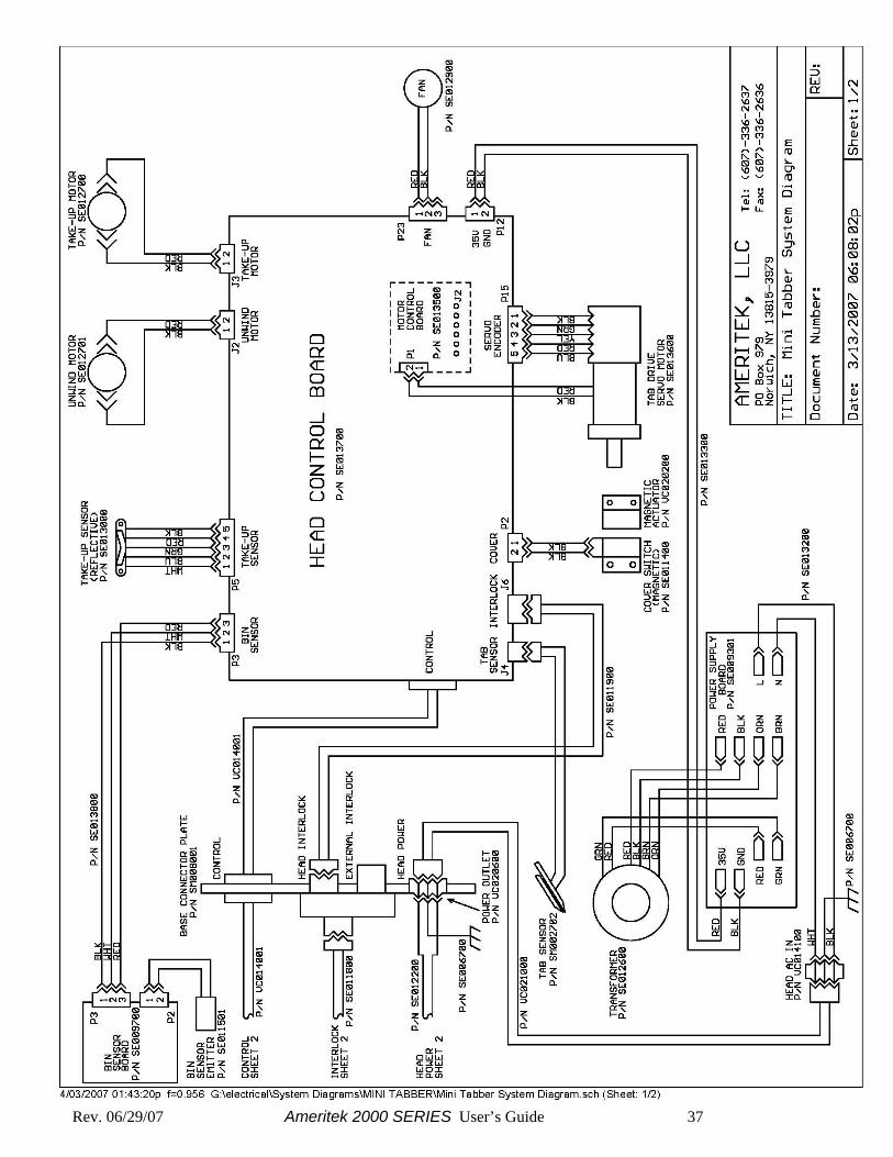
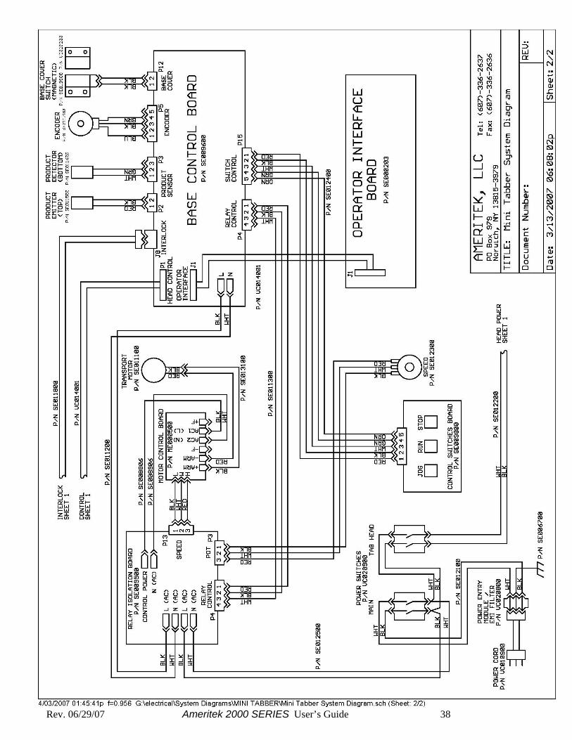
Chapter 7 – Appendix –System diagrams
Rev. 06/29/07 Ameritek 2000 SERIES User’s Guide 37
Rev. 06/29/07 Ameritek 2000 SERIES User’s Guide 38