Embed Size (px)
Citation preview

°C
2002 MAIN ASSEMBLY WITH SIGNAL CONDITIONERS
-P PROCESS-E EXCITATION SUPPLY-S STRAIN/MICROVOLT
11192ML-01
Owners Manual

TABLE OF CONTENTS PAGE
1.0 GENERAL INFORMATION
1.1 Model 2002B-P1.2 Model 2002B-E1.3 Model 2002B-S
2.0 SPECIFICATIONS
2.1 Analog Input2.2 Accuracy at 25_C2.3 Noise Rejection2.4 Excitation Supply2.5 Analog-to-Digital Conversion2.6 Digital Inputs2.7 Display2.8 Power2.9 Environmental2.10 Mechanical
3.0 MECHANICAL ASSEMBLY AND INSTALLATION
3.1 Safety Considerations3.2 Panel Mounting
4.0 POWER & SIGNAL INPUT CONNECTIONS (TB1)
4.1 Installing Option C14.2 Power Connections4.3 Signal Connections4.4 Main Board Connector Pin Assignments (J1)
5.0 MAIN BOARD CONFIGURATION
5.1 Decimal Point Selectio5.2 Model 2002B-P5.3 Models 2002B-E and 2002B-S
6.0 PLUG-IN CARD CONFIGURATION
6.1 Model 2002B-P6.2 Model 2002B-E6.3 Model 2002B-S
7.0 CALIBRATION
8.0 DRAWINGS
9.0 APPLICATION NOTES
9.1 Excitation Supply/Current Transmitter Interface

ILLTABLE OF CONTENTS PAGE
1.0GENERAL INFORMATION
1.1 Model 2002B-P1.2 Model 2002B-E1.3 Model 2002B-S
2.0SPECIFICATIONS
2.1 Analog Input2.2 Accuracy at 25_C2.3 Noise Rejection2.4 Excitation Supply2.5 Analog-to-Digital Conversion2.6 Digital Inputs2.7 Display2.8 Power2.9 Environmental2.10 Mechanical
3.0MECHANICAL ASSEMBLY AND INSTALLATION
3.1 Safety Considerations3.2 Panel Mounting

PAGE
4.0 POWER & SIGNAL INPUT CONNECTIONS (TB1)
4.1 Installing Option C14.2 Power Connections4.3 Signal Connections4.4 Main Board Connector Pin Assignments (J1)
5.0 MAIN BOARD CONFIGURATION
5.1 Decimal Point Selection5.2 Model 2002B-P5.3 Models 2002B-E and 2002B-S
6.0 PLUG-IN CARD CONFIGURATION
6.1 Model 2002B-P6.2 Model 2002B-E6.3 Model 2002B-S
7.0 CALIBRATION
8.0 DRAWINGS
9.0 APPLICATION NOTES
9.1 Excitation Supply/Current Transmitter Interface

ILUSTRATIONS PAGE
Figure 3-1 DIN Case Dimensions
Figure 3-2 Exploded View
Figure 4-1 Changing Operating Voltage
Figure 4-2 Rear View of Case with Connectors
Figure 5-1 Display Board Jumper Locations
Figure 5-2 Main Board Jumper Locations
Figure 6-1 -P Card Jumper Locations
Figure 6-2 -E Card Jumper Locations
Figure 6-3 -S Card Jumper Locations
Figure 8-1 Main Board Assembly Diagram
Figure 8-2 Main Board Schematic Diagram
Figure 8-3 Plug-in Card Assembly -E or -P Diagram
Figure 8-4 Plug-in Card Schematic -E or -P Diagram
Figure 8-5 Plug-in Card Assembly -S Diagram
Figure 8-6 Plug-in Card Schematic -S Diagram
Figure 9-1 Two-wire Connection
Figure 9-2 Four-wire Connection

1.0 GENERAL INFORMATION
The 2002B series provides several versions of a low-cost, four and one-half digit panel meter for a wide range of applica-tions that require accurate DC measurement with zero and span adjustments.
1.1 MODEL 2002B-P
The 2002B-P consists of a main assembly and a plug-in process receiver board.
Model 2002B-P is a process receiver with adjustments of 40,000 counts of zero and 20,000 counts of span for transmit-ter signals such as 4-20 mA, 1-5 V, and 0-10 V. The meter can be scaled to display readings directly in engineering units.
Model 2002B-P can also be used in ratiometric pot-follower applications, to determine such things as liquid level or valvesetting from the position of a potentiometer wiper. The required external reference voltage can be derived from the meter’s4.7 V dc supply.
1.2 MODEL 2002B-E
The 2002B-E consists of a main assembly and a process receiver with excitation board.
In addition to all Model 2002B-P features, Model 2002B-E offers an electrically-floating supply for powering transmitters,active transducers, and bridges. Supply voltage is adjustable from 10 to 24 V dc up to a maximum output current of 50mA. (See Section 9.1)
1.3 MODEL 2002B-S
The 2002B-S consists of a main assembly and a preamplifier with excitation board.
In addition to most 2002B-E features (with the exception that excitation maximum output current decreases from 30 mAat 10 V dc to 20 mA at 24 V dc), Model 2002B-S offers a high-impedance, precision preamplifier with programmable gainsof 1, 3, 10, 30, and 100. Gains provide resolutions of 100, 30, 10, 3, and 1_V/count, respectively. Typical offset drift isonly 0.3 _V/_C. The preamplifier is ideal for metal-foil, strain-gauge applications that require microvolt resolution.2.0 SPECIFICATIONS
2.1 ANALOG INPUT
Models 2002B-P and 2002B-ERange 4-20 mA 1-5 V 0-10 VResolution 0.8 _A 0.2 mV 0.5 mVInput resistance 130 _ 1 M_ 1 M_Bias current 50 pA 10 pA 5 pAMaximum input 55 mA 250 V 250 VConfiguration Differential with respect to AC earth ground, bipolarZero range -20,000 to +20,000 counts with multiturn potsSpan range 0 to 20,000 counts with multiturn potsNMR 70 dB at 50/60 HzReference:
Internal (standard) 1.0 V dc _5% with 12 k_ source resistanceExternal (ratiometric) 0.5 - 2.0 V, 680 k_ input resistance
Model 2002B-SRange
Most-sensitive scaling _19.999 mV, 10 _V resolutionLeast-sensitive scaling _2.5 V, 1 mV resolution (limited by CMV)
Input resistance 1 G_ min without bridge balance

Bias current 1 nA typ, 5 nA maxMaximum input 50 VConfiguration Differential with respect to AC earth ground, bipolarCoarse preamplifier gains 1, 3, 10, 30, 100Bridge balance adj. _1.5 mV with 350 _ bridgeZero range -20,000 to +20,000 counts with multiturn potsSpan range 0 - 20,000 counts with multiturn potsNMR 80 dB at 50/60 Hz for 20 mV range; 66 dB at
50/60 Hz for 0.2 and 2.0 V rangesReference:
Internal (from excitation 1.0 V dc with 9.5 k_ source resistance at supply) 10 V dc excitation
External (opt) 1.0 V dc -50%/+100% with 680 k_ inputresistance
2.2 ACCURACY AT 25_C
Models 2002B-P, 2002B-E, and 2002B-S
Step response 1 secondWarmup to rated accuracy 10 minutes
Models 2002B-P and 2002B-EMaximum error _0.01% of span _2 countsSpan tempco _0.01% of span/_CZero tempco _0.5 counts/_C
Model 2002B-S
Reference Internal ExternalMaximum error _0.01% S _2 countsSpan tempco _0.005% S/_C _0.01% S/_CZero tempco _0.5 _V/_C _1.0 counts/_CBridge balance tempco _0.5 _V/_C _0.2 _V/_C
2.3 NOISE REJECTION
CMR, SIG GND to PWR GND 120 dB from DC to 60 HzCMV, SIG GND to PWR GND 1500 Vp per HV test;
354 Vp per IEC spacing 2.4 EXCITATION SUPPLY
Models 2002B-E and 2002B-SOutput voltage Adjustable from 10 to 24 V dc with multiturn potOutput current 50 mA max for -E; 30 mA max at 10 V decreasing to 12 mA max at 24 V for -SLoad regulation* 0.15% typ, 0.5% max from zero to max loadLine regulation* 0.01% typ, 0.04% max for 10% change of AC power voltageTempco* 0.02%/_C maxRipple at 50/60 Hz 0.01%
* In Model 2002B-S, the meter’s internal reference (e.g., 1 V at 10 V excitation) is derived from the excitation voltage forratiometric operation which eliminates load and line regulation errors and reduces other errors.2.5 ANALOG-TO-DIGITAL CONVERSION
Technique Dual-slope, average-valueInput integration period 100 millisecondsRead rate 2.5/seconds
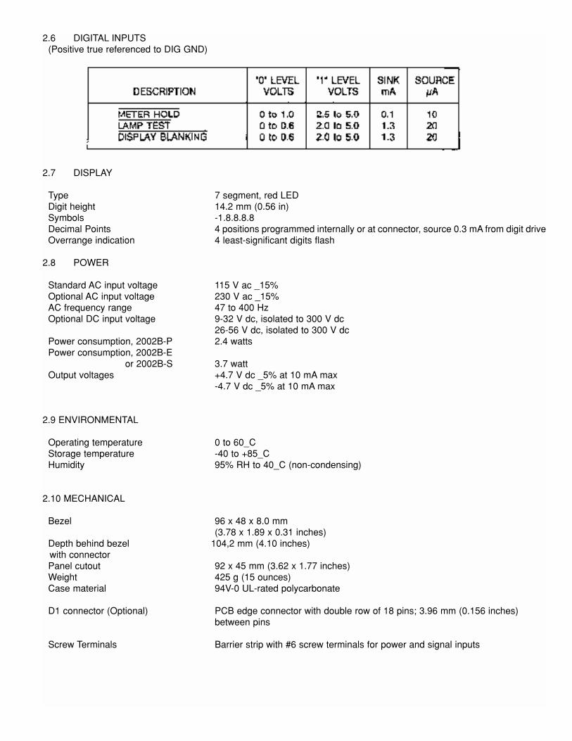
2.6 DIGITAL INPUTS(Positive true referenced to DIG GND)
2.7 DISPLAY
Type 7 segment, red LEDDigit height 14.2 mm (0.56 in)Symbols -1.8.8.8.8Decimal Points 4 positions programmed internally or at connector, source 0.3 mA from digit driveOverrange indication 4 least-significant digits flash
2.8 POWER
Standard AC input voltage 115 V ac _15%Optional AC input voltage 230 V ac _15%AC frequency range 47 to 400 HzOptional DC input voltage 9-32 V dc, isolated to 300 V dc
26-56 V dc, isolated to 300 V dcPower consumption, 2002B-P 2.4 wattsPower consumption, 2002B-E
or 2002B-S 3.7 wattOutput voltages +4.7 V dc _5% at 10 mA max
-4.7 V dc _5% at 10 mA max
2.9 ENVIRONMENTAL
Operating temperature 0 to 60_CStorage temperature -40 to +85_CHumidity 95% RH to 40_C (non-condensing)
2.10 MECHANICAL
Bezel 96 x 48 x 8.0 mm(3.78 x 1.89 x 0.31 inches)
Depth behind bezel 104,2 mm (4.10 inches)with connectorPanel cutout 92 x 45 mm (3.62 x 1.77 inches)Weight 425 g (15 ounces)Case material 94V-0 UL-rated polycarbonate
D1 connector (Optional) PCB edge connector with double row of 18 pins; 3.96 mm (0.156 inches)between pins
Screw Terminals Barrier strip with #6 screw terminals for power and signal inputs

3.0 MECHANICAL ASSEMBLY AND INSTALLATION
3.1 SAFETY CONSIDERATIONSThis instrument is protected according to Class I (Protective Earth) of the IEC (International Electrotechnical Commission)348 and the VDE 0411 regulations. To ensure safe operation, follow the guidelines below:
VISUAL INSPECTION: Do not attempt to operate the instrument if damage is found.
POWER VOLTAGE: This instrument is delivered with the AC power input connected for 240 V ac in Europe (C1 option)
or 120 V ac in the USA (unless the instrument is provided with the DC power input option). Verify that the instrument is
connected for the correct power voltage rating before using. If incorrect, make the required changes as described in
Section 4.
POWER WIRING: This instrument has no power switch; it will be in operation as soon as the power is connected.Verify that the power cable has the proper ground (earth) wire and that this wire is properly connected to an adequateground (earth) point. The meter must be grounded in accordance with the latest local safety regulations.
If AC, the power cable must contain a protective ground conductor which is not disconnected (open) either inside or out-
side the instrument. No extension cables without grounding wires shall be used.
SIGNAL WIRING: Do not make signal wiring connections or changes while power is on.
RAIN OR MOISTURE: Do not expose the instrument to condensing moisture.
FUMES AND GASES: Do not operate the instrument in the presence of flammable gases or fumes.
EXERCISE CAUTION: As with any electronic instrument, high voltages may be exposed when attempting to install, cali-brate, or remove parts of the meter.

3.2 PANEL MOUNTING NOTE: Dimensions are in millimeters _0,25 mmand inches are in ( ) _0.01 in.
Figure 3-1 DIN Case Dimensions

Figure 3-2 Exploded View
1. Remove main board edge connector J1, if installed.2. Loosen the two clamp screws on rear of case until slide clamps can be rotated. Push the two slide retainers towardthe rear of the case, and remove them.
3. Working from the front of the panel, insert the meter into the panel cutout.4. Insert slide retainers back onto the case, and push them up tightly against the rear of the panel.5. Rotate slide clamps back into original position and tighten clamp screws just enough to hold the case in place.NEVER OVERTIGHTEN CLAMP SCREWS.
6. Install any connectors that have been removed.4.0 POWER AND SIGNAL INPUT CONNECTIONS (TB1)
CAUTION: Incorrect power input can damage your panel meter.
4.1 INSTALLING OPTION C1 (230 V ac)If this option is to be used, it must be installed prior to any power and signal connections. Option C1 is 230 V ac _15%,47-400 Hz operation. To change the meter in the field from 115 V ac operation, follow this procedure:1. Refer to Figures 4-1 and 4-2. Remove power lines from the meter, then remove the meter from the case.
2. Remove jumpers W5 and W6 on the transformer.3. Add jumper W4 on the printed circuit board. The meter is now wired for 230 V ac operation.
NOTE: To change the meter from 230V ac to 115V ac operation, reverse the above procedure.

Figure 4-1 Changing Operating Voltage
Figure 4-2 Rear View of Case with Connectors
4.2 POWER CONNECTIONS
[

4.3 SIGNAL INPUT CONNECTIONS
4.4 MAIN BOARD CONNECTOR PIN ASSIGNMENTS (J1)
(Left to right, looking at rear of case)
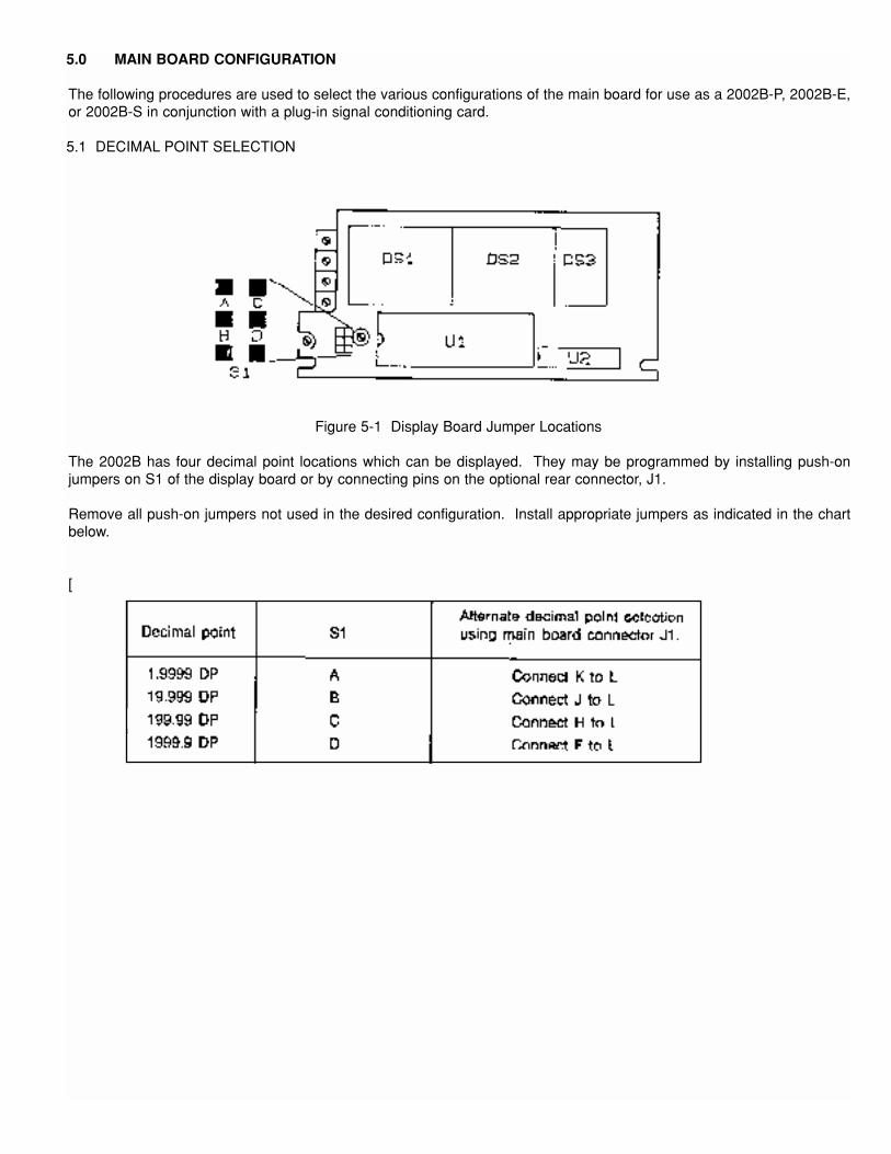
5.0 MAIN BOARD CONFIGURATION
The following procedures are used to select the various configurations of the main board for use as a 2002B-P, 2002B-E,or 2002B-S in conjunction with a plug-in signal conditioning card.
5.1 DECIMAL POINT SELECTION
Figure 5-1 Display Board Jumper Locations
The 2002B has four decimal point locations which can be displayed. They may be programmed by installing push-onjumpers on S1 of the display board or by connecting pins on the optional rear connector, J1.
Remove all push-on jumpers not used in the desired configuration. Install appropriate jumpers as indicated in the chartbelow.
[

5.2 MODEL 2002B-P
Figure 5-2 Main Board Jumper Locations
The 2002B-P main board is generally configured to use the internal absolute reference rather than an external ratiometricone. The three input ranges for this are listed in the chart below.
5.3 MODELS 2002B-E AND 2002B-S
The 2002B-E main board may be configured to use one of three input ranges.
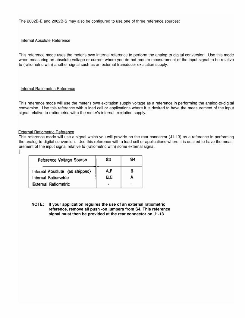
The 2002B-E and 2002B-S may also be configured to use one of three reference sources:
Internal Absolute Reference
This reference mode uses the meter's own internal reference to perform the analog-to-digital conversion. Use this modewhen measuring an absolute voltage or current where you do not require measurement of the input signal to be relativeto (ratiometric with) another signal such as an external transducer excitation supply.
Internal Ratiometric Reference
This reference mode will use the meter's own excitation supply voltage as a reference in performing the analog-to-digitalconversion. Use this reference with a load cell or applications where it is desired to have the measurement of the inputsignal relative to (ratiometric with) the meter's internal excitation supply.
External Ratiometric ReferenceThis reference mode will use a signal which you will provide on the rear connector (J1-13) as a reference in performingthe analog-to-digital conversion. Use this reference with a load cell or applications where it is desired to have the meas-urement of the input signal relative to (ratiometric with) some external signal.[
NOTE: If your application reguires the use of an external ratiometricreference, remove all push -on jumpers from S4. This reference signal must then be provided at the rear connector on J1-13

6.0 PLUG-IN CARD CONFIGURATION
6.1 Model 2002B-P
Remove all push-on jumpers not used in the desired configuration. Install appropriate jumpers as indicated.
Figure 6-1 -P Card Jumper Locations
The 2002B-P plug-in card should have push-on jumpers installed on positions S1-A and S1-C.
6.2 Model 2002B-E
Remove all push-on jumpers not used in the desired configuration. Install appropriate jumpers as indicated.
Figure 6-2 -E Card Jumper Locations
The 2002B-E plug-in card should be configured according to the type of reference for which the main board was config-ured.
* Zero Offset is derived from this reference.

6.3 Model 2002B-SRemove all push-on jumpers not used in the desired configuration. Install appropriate jumpers as indicated.
Figure 6-3 -S Card Jumper Locations
The 2002B-S plug-in card should be configured according to the type of reference for which the main board was config-ured.
* Zero Offset is derived from this reference.
7.0 CALIBRATION
Using the upper and lower signals as well as the upper and lower display readings required by your application, calculatethe slope factor (S):
Upper Input (UI) Upper Display (UD)
Lower Input (LI) Lower Display (LD)
UD - LDS =

UI - LI
Then calculate the Top Calibration Point (TCP):
TCP = S x UI
Example: If you wanted an input of 4 to 20 mA to produce display readings of 1000 to 10000:
UI = 20 UD = 10000LI = 4 LD = 1000
10000 - 1000 = 562.5
S = 20 - 4
TCP = 562.5 x 20 = 11250

After determining LI, UI, LD, UD, S, and TCP for your application, you will be ready to commence with the following pro-cedure. Refer to Figure 3-1 to locate the calibration potentiometers.
1. If you are using a 2002B-E or a 2002B-S, adjust Excitation Voltage (R14) as required for your application.
2. Center the position of the Fine Span (R32) and Fine Zero (R36) by turning them 20 turns clockwise and then about8 to 10 turns counter-clockwise.
3. Apply an input of zero volts or milliamperes (depending on your configuration). Adjust Coarse Zero (R16) until themeter displays 0000.
4. Apply the Upper Input signal and adjust the Coarse Span (R17) until the meter displays the TCP reading.
5. Apply the Lower Input signal and adjust the Coarse Zero (R16) until the meter displays the Lower Display reading.
6. Apply the Upper Input signal and adjust Fine Span (R32) until the meter displays the Upper Display reading.
7. Apply the Lower Input signal and adjust Fine Zero (R36) until the meter displays the Lower Display reading.
NOTE: If you are using a 2002B-S, a bridge balance adustment (R15) is availableto null any errors which may exist in your load cell bridge. A resistor may beinstalled at R5 on the plug-in board if R15 does not provide enough adjustment.

8.0 DRAWINGS
Figure 8-1 Main Board Assembly Diagram

Figure 8-2 Main Board Schematic Diagram

Figure 8-3 Plug-in Card Assembly -E or -P Diagram
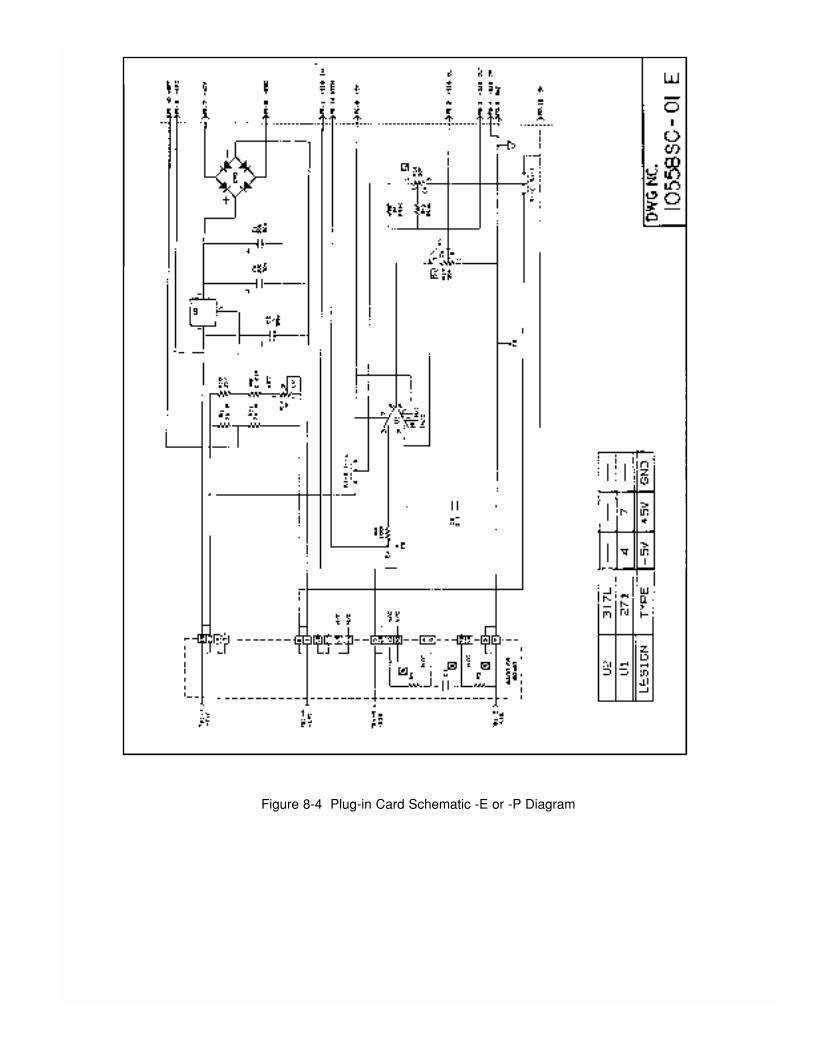
Figure 8-4 Plug-in Card Schematic -E or -P Diagram
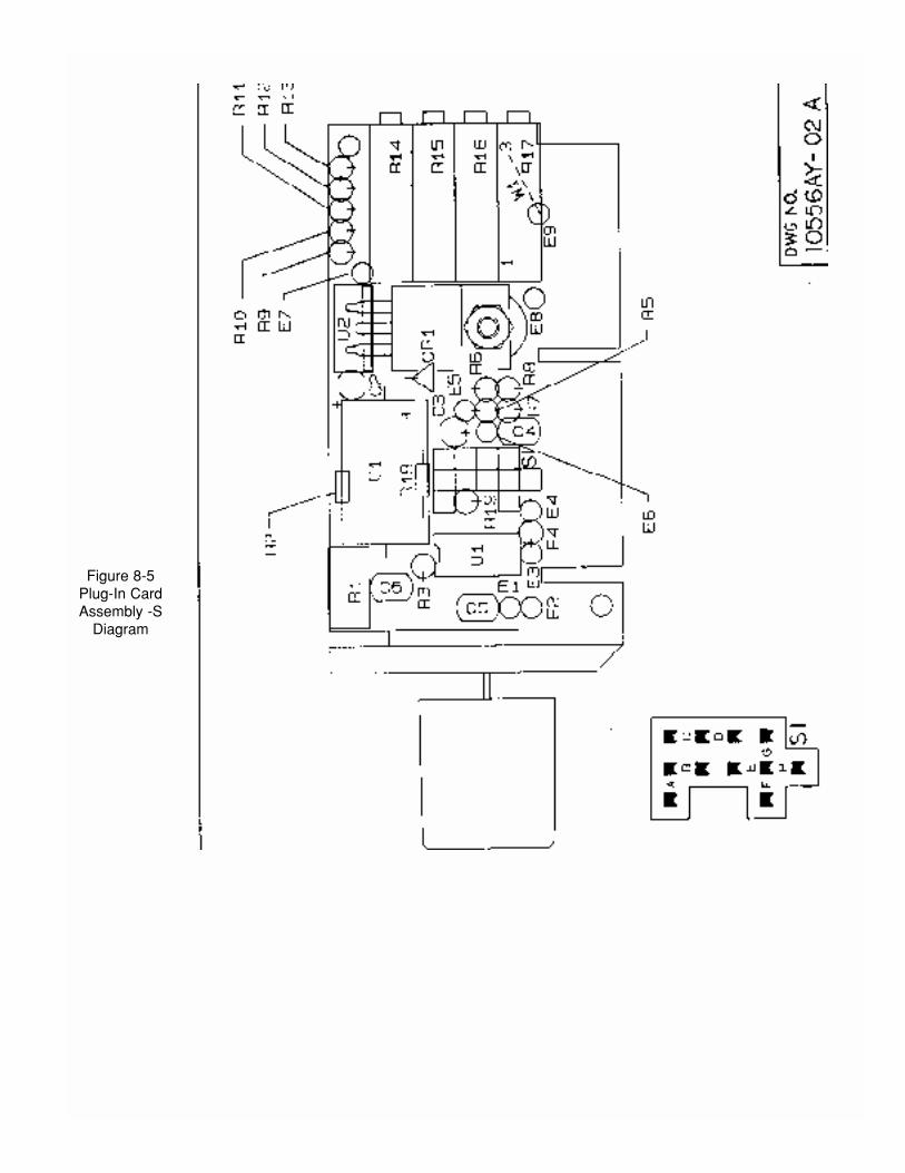
Figure 8-5Plug-In CardAssembly -S
Diagram


Figure 8-6 Plug-In Card Schematic -S Diagram9.0 APPLICATION NOTES
9.1 Excitation Supply/Current Transmitter Interface
The following block diagrams show the proper hookup for interfacing an electrically-floating excitation supply with eithera 2-wire or a 4-wire current transmitter (4-20 mA loop-powered).
Figure 9-1 Two-wire Connection
Figure 9-2 Four-wire Connection
NOTE: For proper operation the unit must be configured for an internal absolute reference. (See Section 5.3)


![INDEX [exceltecinc.com] · Signal Conditioners Tutorial 6 A quick overview for signal conditioners. SC-FI 7 Frequency to current signal conditioner. SC-II 9 Current to current isolator](https://img.pdfslide.net/doc/110x75/5f63f0b95c835b58a2452785/index-signal-conditioners-tutorial-6-a-quick-overview-for-signal-conditioners.jpg)