Embed Size (px)
Citation preview
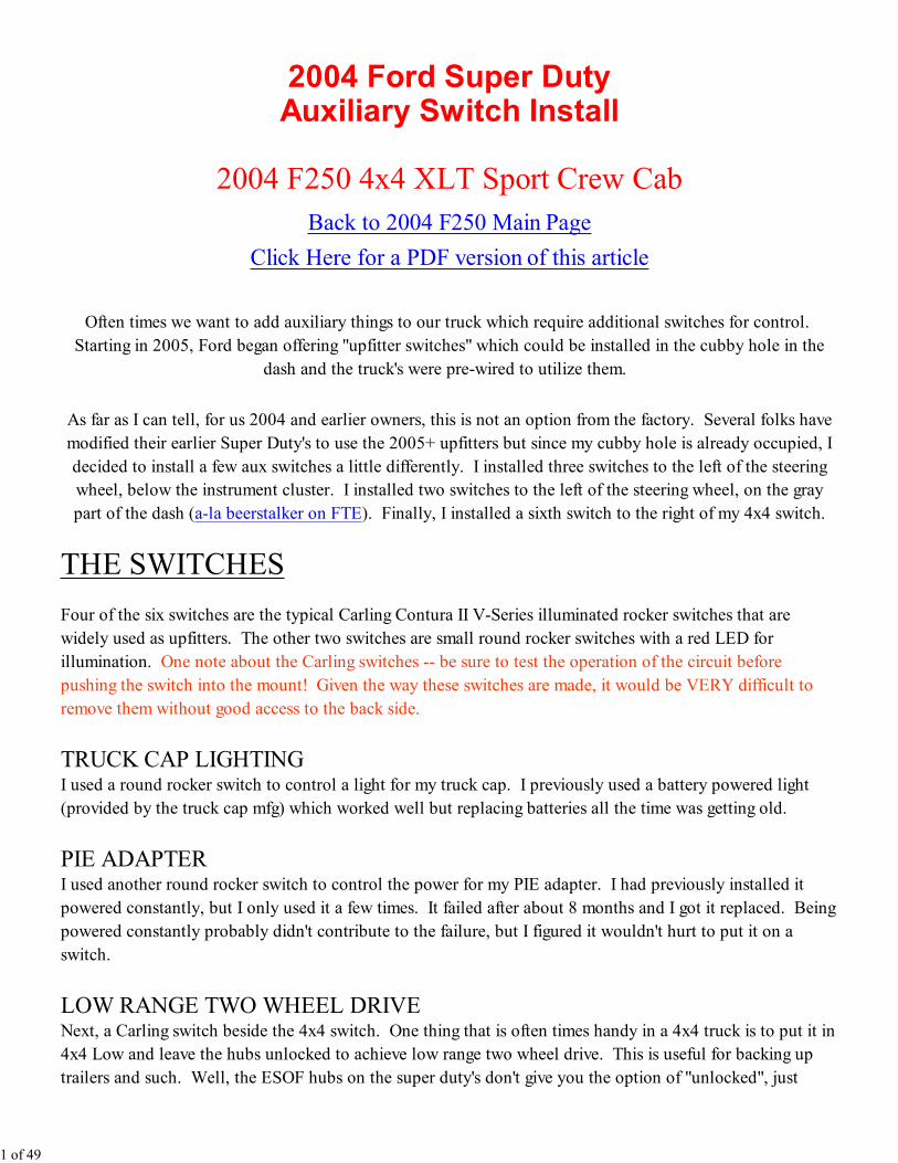
2004 Ford Super DutyAuxiliary Switch Install
2004 F250 4x4 XLT Sport Crew Cab
Back to 2004 F250 Main Page
Click Here for a PDF version of this article
Often times we want to add auxiliary things to our truck which require additional switches for control.
Starting in 2005, Ford began offering "upfitter switches" which could be installed in the cubby hole in the
dash and the truck's were pre-wired to utilize them.
As far as I can tell, for us 2004 and earlier owners, this is not an option from the factory. Several folks have
modified their earlier Super Duty's to use the 2005+ upfitters but since my cubby hole is already occupied, I
decided to install a few aux switches a little differently. I installed three switches to the left of the steering
wheel, below the instrument cluster. I installed two switches to the left of the steering wheel, on the gray
part of the dash (a-la beerstalker on FTE). Finally, I installed a sixth switch to the right of my 4x4 switch.
THE SWITCHES
Four of the six switches are the typical Carling Contura II V-Series illuminated rocker switches that are
widely used as upfitters. The other two switches are small round rocker switches with a red LED for
illumination. One note about the Carling switches -- be sure to test the operation of the circuit before
pushing the switch into the mount! Given the way these switches are made, it would be VERY difficult to
remove them without good access to the back side.
TRUCK CAP LIGHTINGI used a round rocker switch to control a light for my truck cap. I previously used a battery powered light
(provided by the truck cap mfg) which worked well but replacing batteries all the time was getting old.
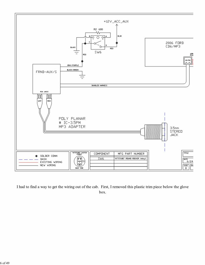
PIE ADAPTERI used another round rocker switch to control the power for my PIE adapter. I had previously installed it
powered constantly, but I only used it a few times. It failed after about 8 months and I got it replaced. Being
powered constantly probably didn't contribute to the failure, but I figured it wouldn't hurt to put it on a
switch.
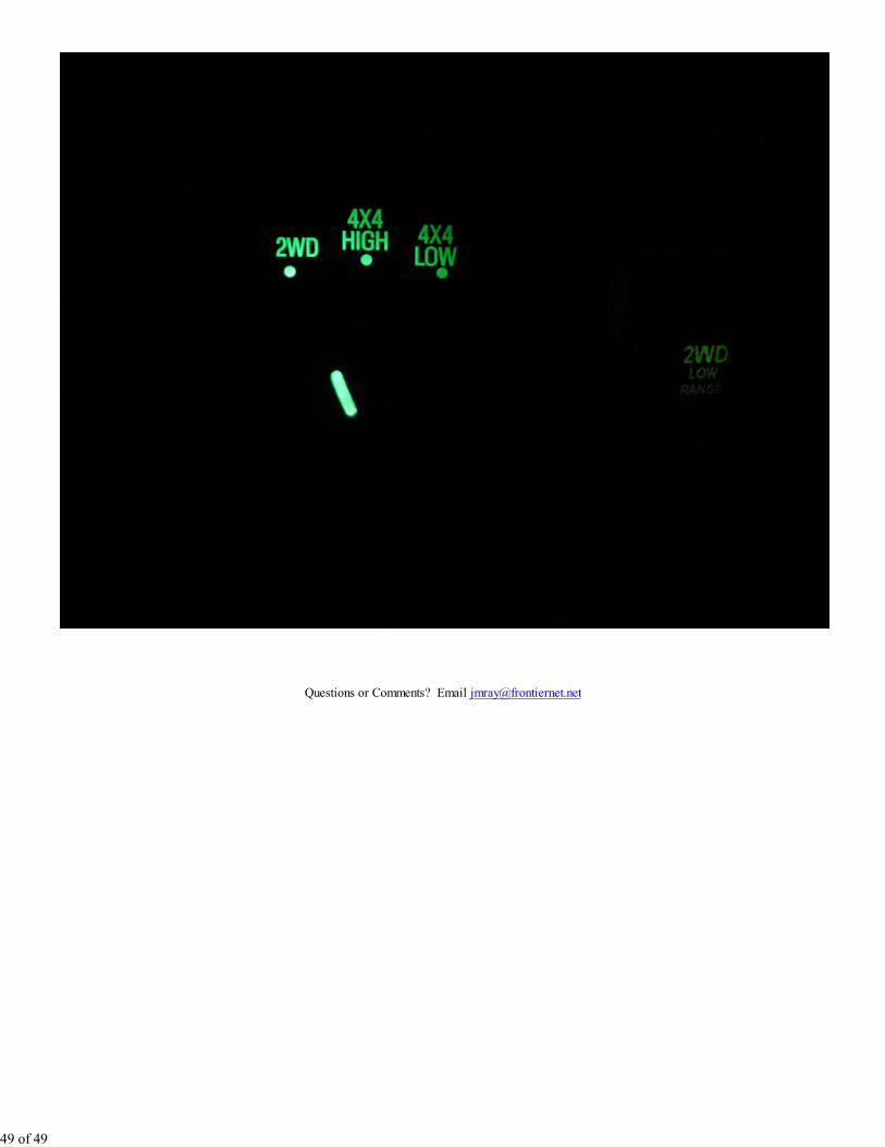
LOW RANGE TWO WHEEL DRIVENext, a Carling switch beside the 4x4 switch. One thing that is often times handy in a 4x4 truck is to put it in
4x4 Low and leave the hubs unlocked to achieve low range two wheel drive. This is useful for backing up
trailers and such. Well, the ESOF hubs on the super duty's don't give you the option of "unlocked", just
1 of 49
"locked" and "auto" so either way your hubs are locked (assuming your ESOF is working properly). Luckily,
interrupting the ESOF vacuum pulses is a fairly easy way to "trick" it into going into low range two wheel
drive.
WINDSHIELD WIPER SHAKERNext, one of the three switches to the left of the steering wheel. I decided to try out the "wiper shaker"
system on this truck. Winter's can be pretty harsh around here and I've been known to hang a left arm out the
window and grab the wiper to "flick" it to try to clear the ice. This system comes with a pushbutton switch,
so I used a normally open momentary switch for this.
BACKUP CAMERASince I installed my backup camera, there's been a few times when I would've liked to use it without shifting
into reverse. This switch allows me to do this.
MIRROR HEATER DISABLE The heated mirrors in our super duty trucks (I think Ford changed this in 2009?) are on any time the key is
on, no matter what. This adds an unnecessary load (8 to 10 amps) on the battery, plus it can cause water
spots on the mirrors, plus I wanted another switch to add to the dash :-)
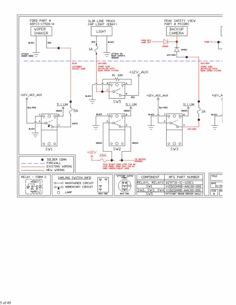
TOOLS & PARTS I USED- Carling illuminated rocker switch part number V1D2GHNB-AAC00-000 (three of these)
- Carling illuminated rocker switch momentary part number V2D2GHNB-AAC00-000
- Round rocker switch - "attitude" switch found on ebay (two of these)
- Carling 3-switch mount part number VM3-01
- Carling single switch mount part number VMS-01
- Ford Wiper Shaker system part number A8FCS-17526-A
- Slim Line truck cap light (ebay)
- superbrightleds.com part number WLED-WHP5 LED
- inline 1/4" x 1-1/4" fuse holder - Radio Shack part number 270-1217
- inline blade type fuse holder - part number HHG (three of these)
- SPDT Automotive Relay part number AZ9731-1C-12DC1 (two of these)
- 20 amp blade type fuse
- 5 position terminal strip (two of these)
- 4.5" x 3.5" x 1.5" plastic enclosure
- 10AWG wire (~10 feet)
- 12AWG wire (several feet, various colors)
- 16AWG wire (several feet, various colors)
- 1N4001 diode
- misc crimp terminals
- Dremel tool & accessories
- Cordless drill
- 3/4" wood drill bit
- 1/8" drill bit
- soldering iron & solder
- Xacto knife blade tip for soldering iron
- Digital multimeter
- Clamp-on DC ammeter
2 of 49
- Handheld infrared thermometer
- various sizes of heat shrink tubing
- normal hand tools (wire strippers, cutters, crimpers, screwdrivers, etc)
- socket set
- Brother P-Touch label maker
- 3/4" label cartridge - black on white
- 3/4" label cartridge - black on clear
PROCEDURE
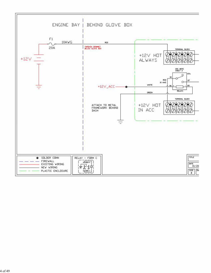
First, in order to accommodate these new circuits, I decided to upgrade the power availability in the cab.
Because of my CB, auto dimming mirror, gauges, PIE adapter, backup camera, rear wiper, etc I've basically
tapped into all the good places to get power. So, I decided to run a 10AWG wire directly from the battery
into the cab. I terminated this onto a terminal strip for "hot always" and I also used a relay to another
terminal strip for "hot in acc".
Here's the schematics for the auxiliary power and the switches.
3 of 49
4 of 49
5 of 49
I had to find a way to get the wiring out of the cab. First, I removed this plastic trim piece below the glove
box.
6 of 49
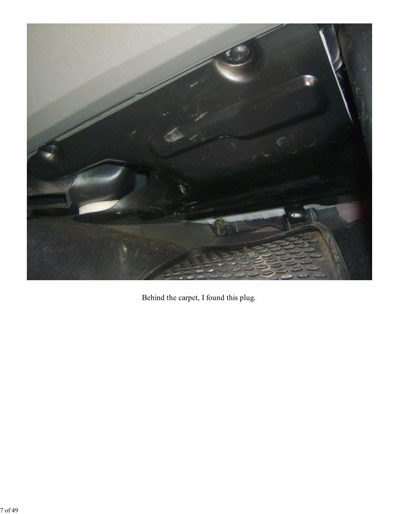
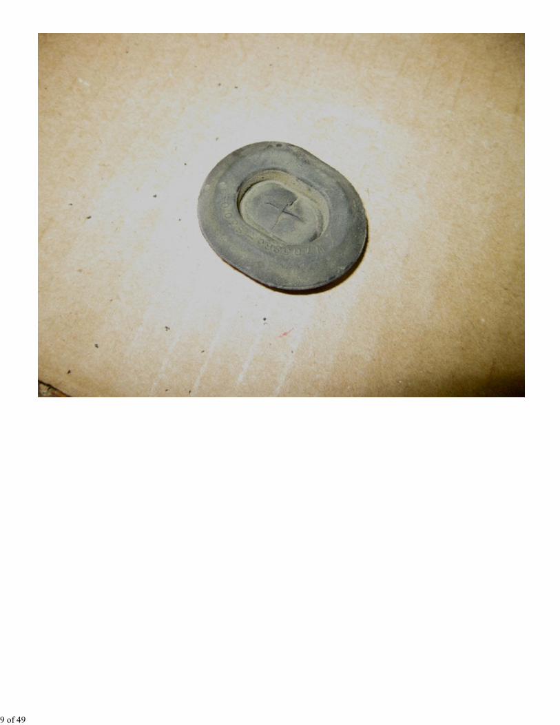
Behind the carpet, I found this plug.
7 of 49
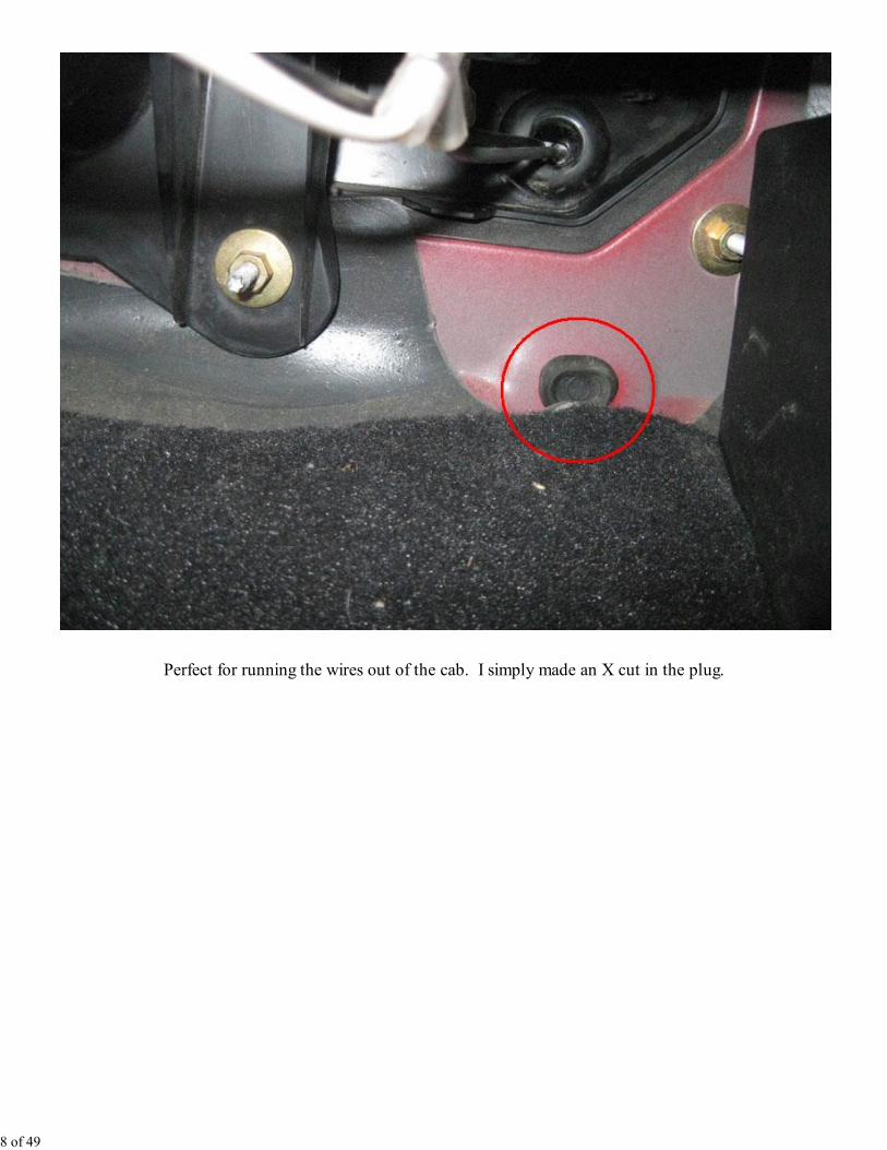
Perfect for running the wires out of the cab. I simply made an X cut in the plug.
8 of 49
9 of 49
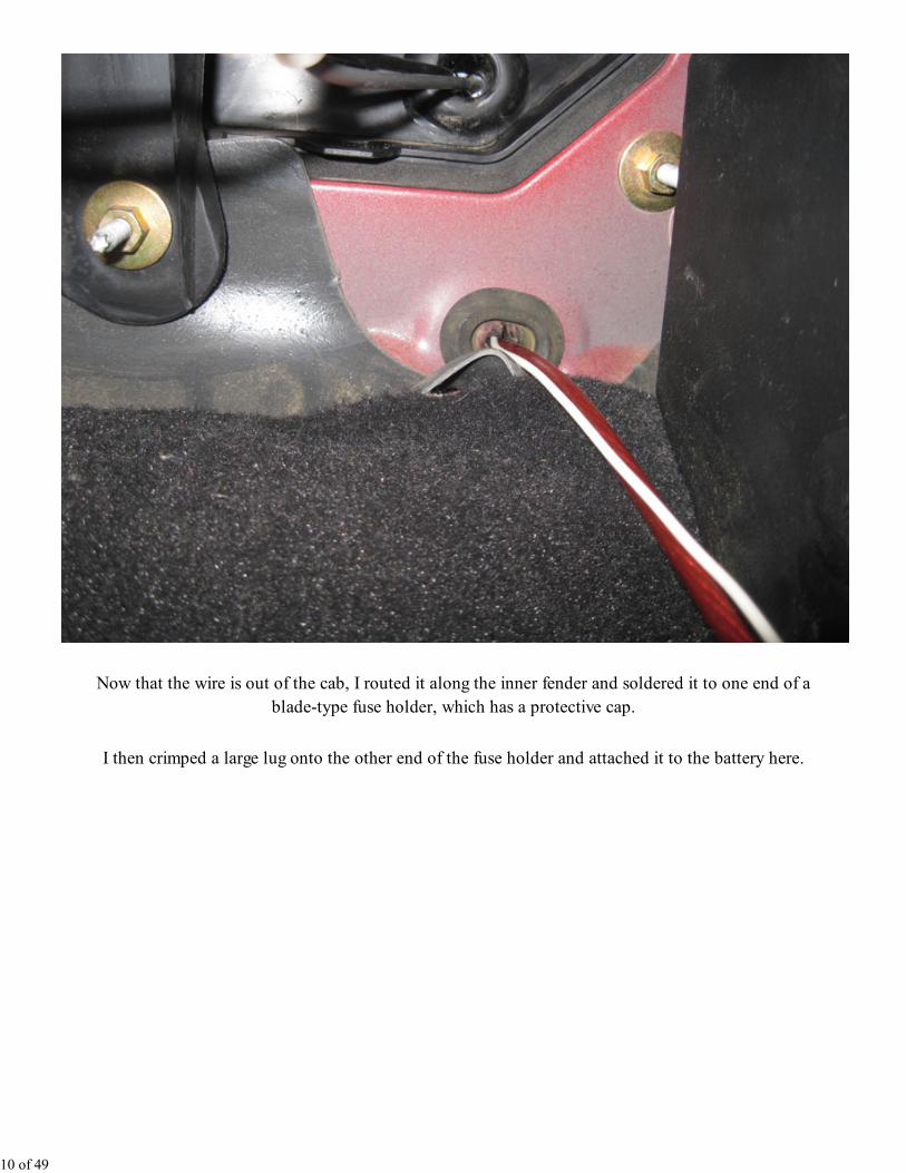
Now that the wire is out of the cab, I routed it along the inner fender and soldered it to one end of a
blade-type fuse holder, which has a protective cap.
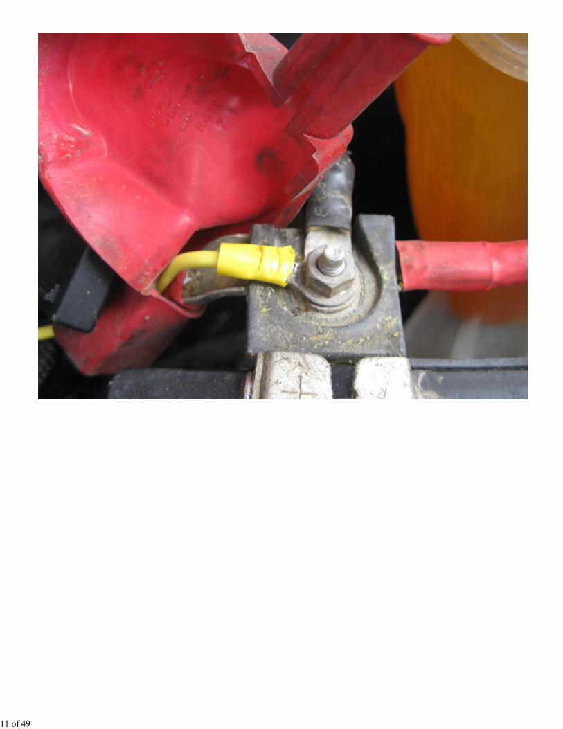
I then crimped a large lug onto the other end of the fuse holder and attached it to the battery here.
10 of 49
11 of 49
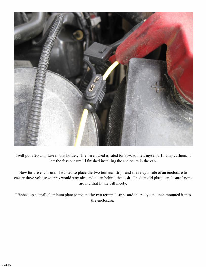
I will put a 20 amp fuse in this holder. The wire I used is rated for 30A so I left myself a 10 amp cushion. I
left the fuse out until I finished installing the enclosure in the cab.
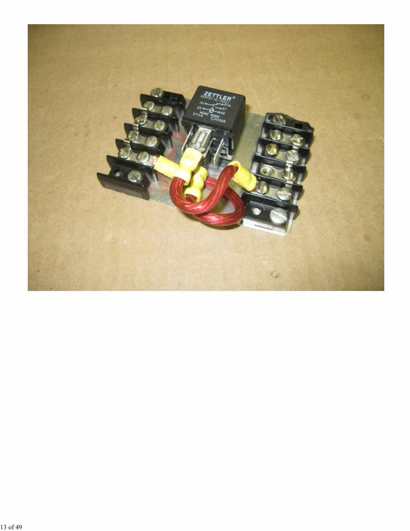
Now for the enclosure. I wanted to place the two terminal strips and the relay inside of an enclosure to
ensure these voltage sources would stay nice and clean behind the dash. I had an old plastic enclosure laying
around that fit the bill nicely.
I fabbed up a small aluminum plate to mount the two terminal strips and the relay, and then mounted it into
the enclosure.
12 of 49
13 of 49
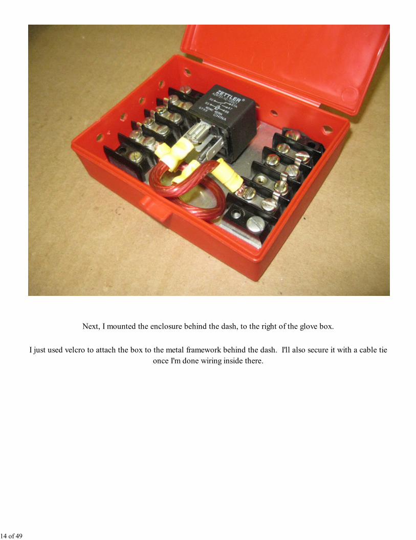
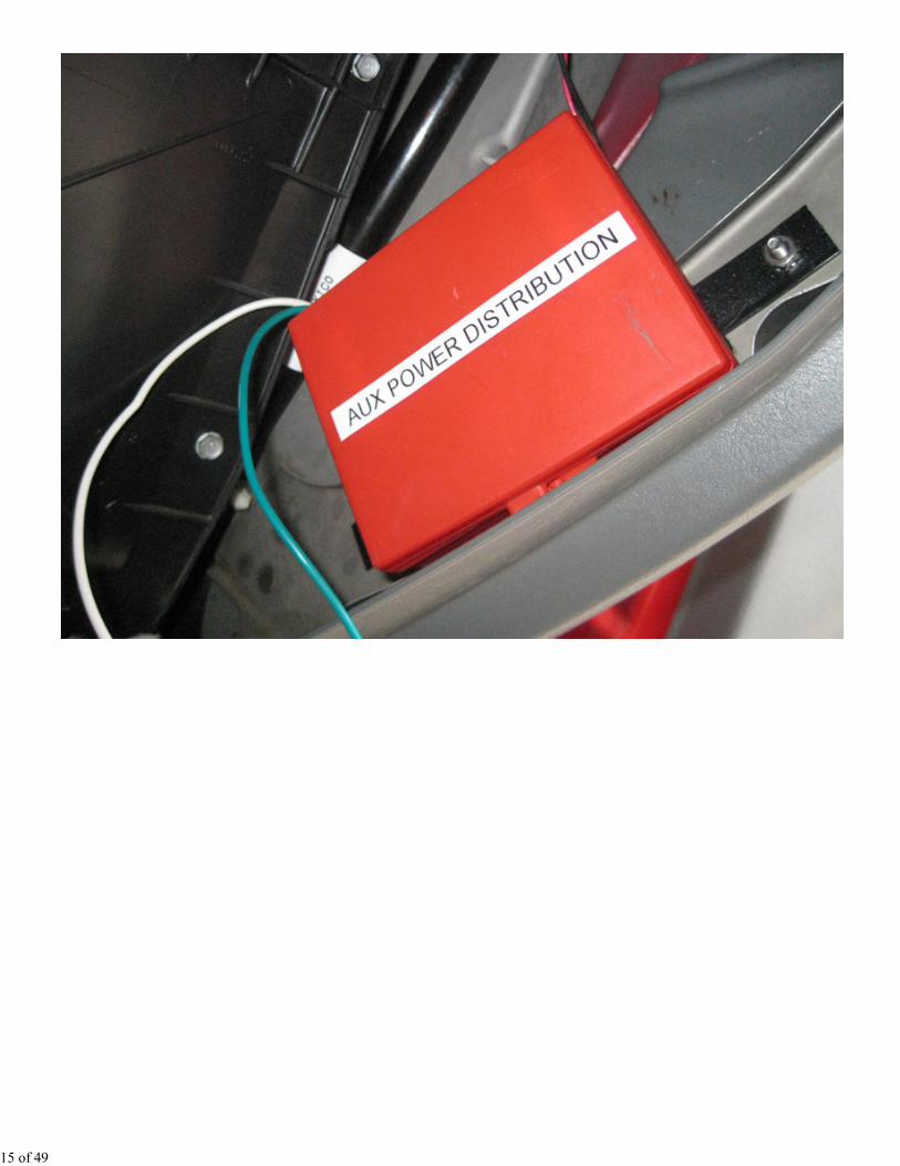
Next, I mounted the enclosure behind the dash, to the right of the glove box.
I just used velcro to attach the box to the metal framework behind the dash. I'll also secure it with a cable tie
once I'm done wiring inside there.
14 of 49
15 of 49
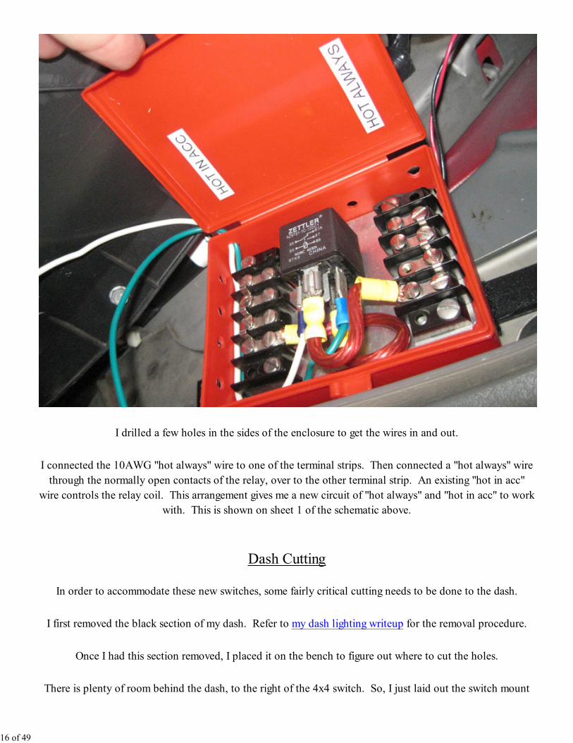
I drilled a few holes in the sides of the enclosure to get the wires in and out.
I connected the 10AWG "hot always" wire to one of the terminal strips. Then connected a "hot always" wire
through the normally open contacts of the relay, over to the other terminal strip. An existing "hot in acc"
wire controls the relay coil. This arrangement gives me a new circuit of "hot always" and "hot in acc" to work
with. This is shown on sheet 1 of the schematic above.
Dash Cutting
In order to accommodate these new switches, some fairly critical cutting needs to be done to the dash.
I first removed the black section of my dash. Refer to my dash lighting writeup for the removal procedure.
Once I had this section removed, I placed it on the bench to figure out where to cut the holes.
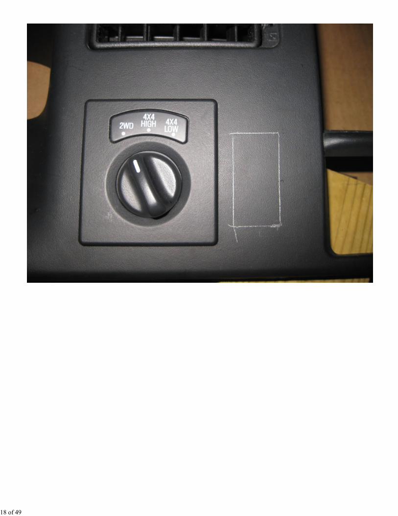
There is plenty of room behind the dash, to the right of the 4x4 switch. So, I just laid out the switch mount
16 of 49
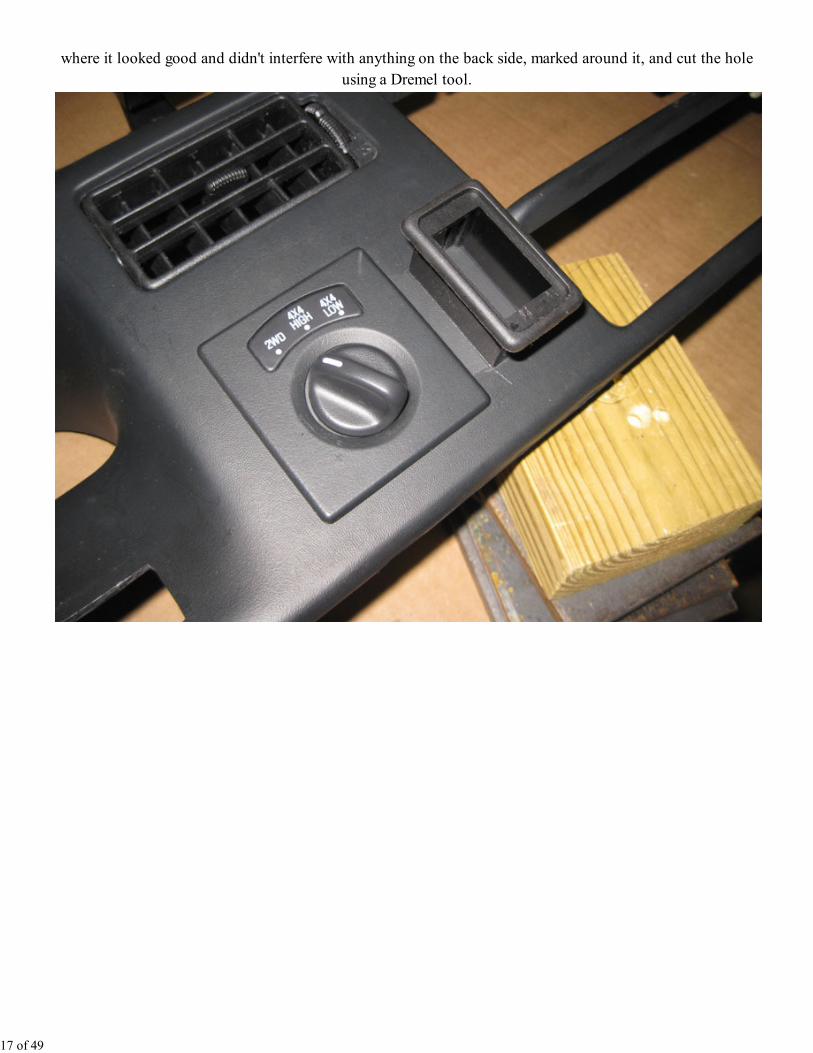
where it looked good and didn't interfere with anything on the back side, marked around it, and cut the hole
using a Dremel tool.
17 of 49
18 of 49
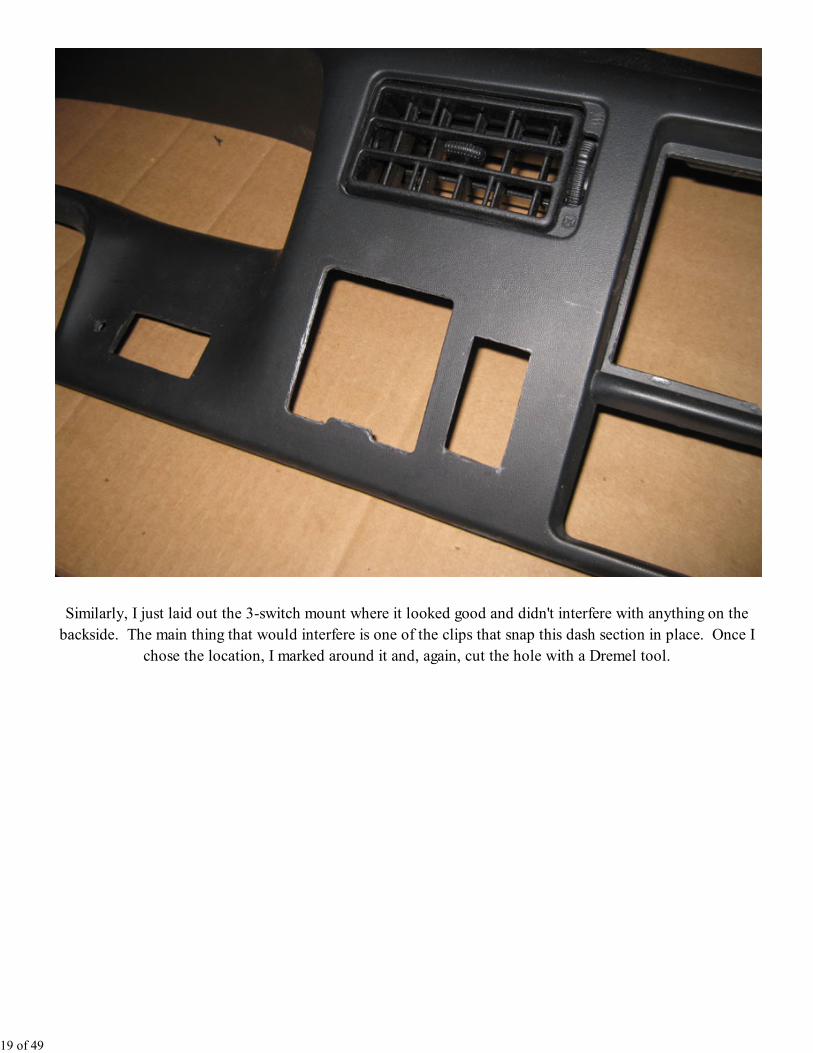
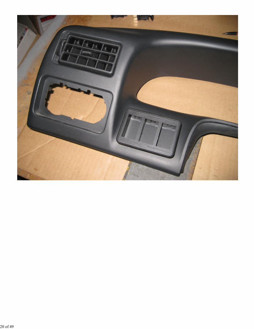
Similarly, I just laid out the 3-switch mount where it looked good and didn't interfere with anything on the
backside. The main thing that would interfere is one of the clips that snap this dash section in place. Once I
chose the location, I marked around it and, again, cut the hole with a Dremel tool.
19 of 49
20 of 49
21 of 49
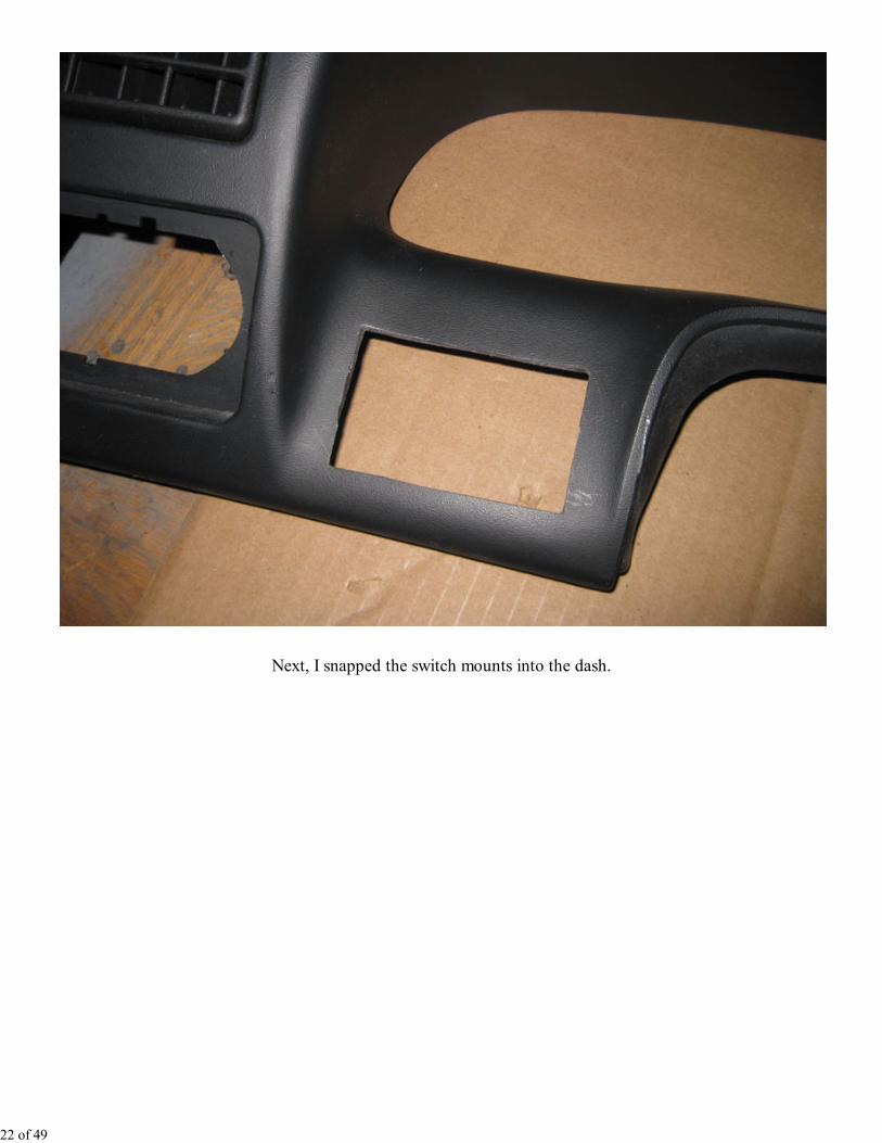
Next, I snapped the switch mounts into the dash.
22 of 49
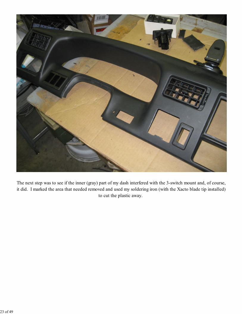
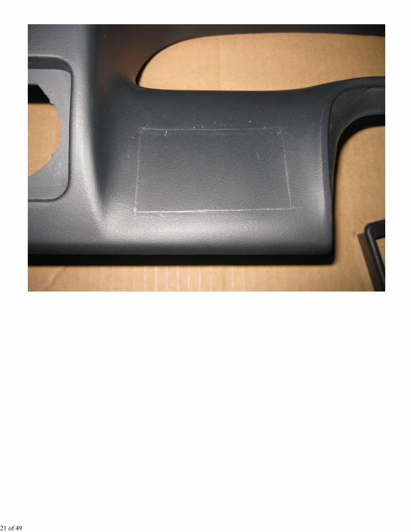
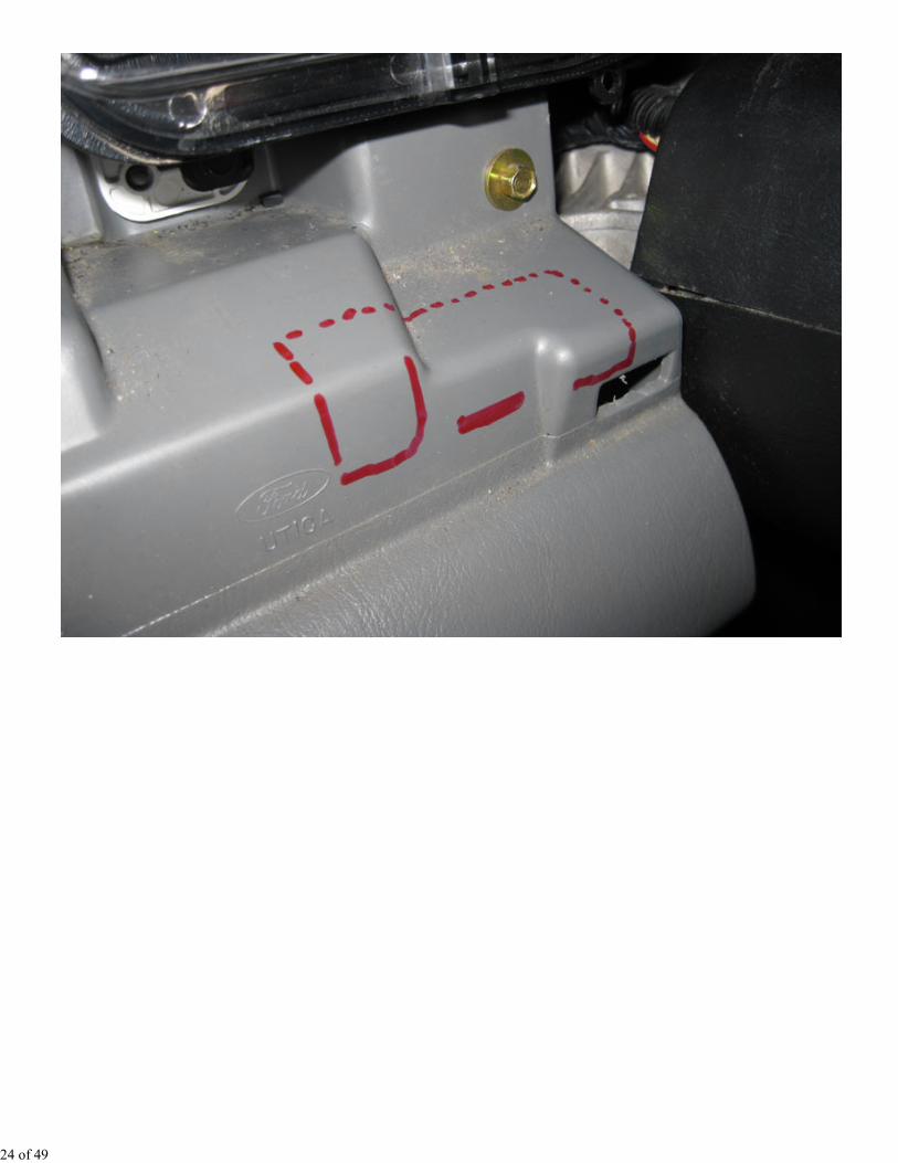
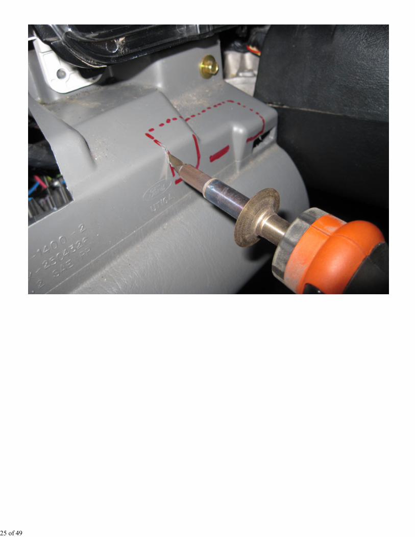
The next step was to see if the inner (gray) part of my dash interfered with the 3-switch mount and, of course,
it did. I marked the area that needed removed and used my soldering iron (with the Xacto blade tip installed)
to cut the plastic away.
23 of 49
24 of 49
25 of 49
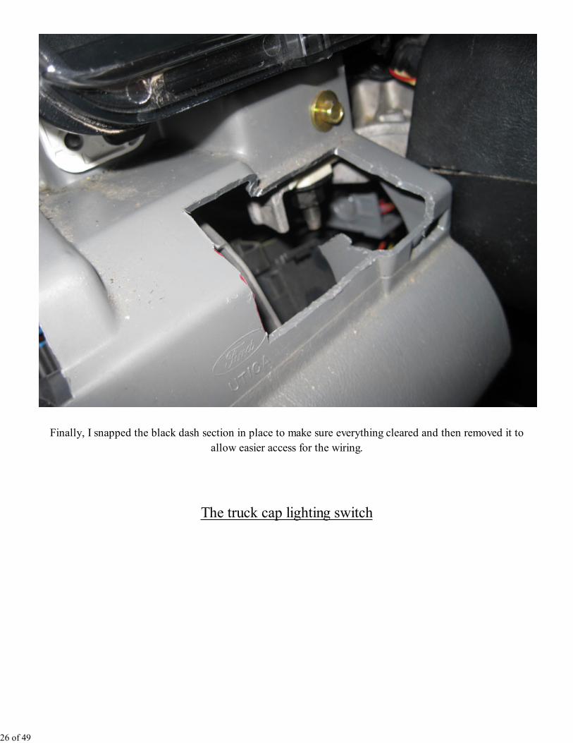
Finally, I snapped the black dash section in place to make sure everything cleared and then removed it to
allow easier access for the wiring.
The truck cap lighting switch
26 of 49
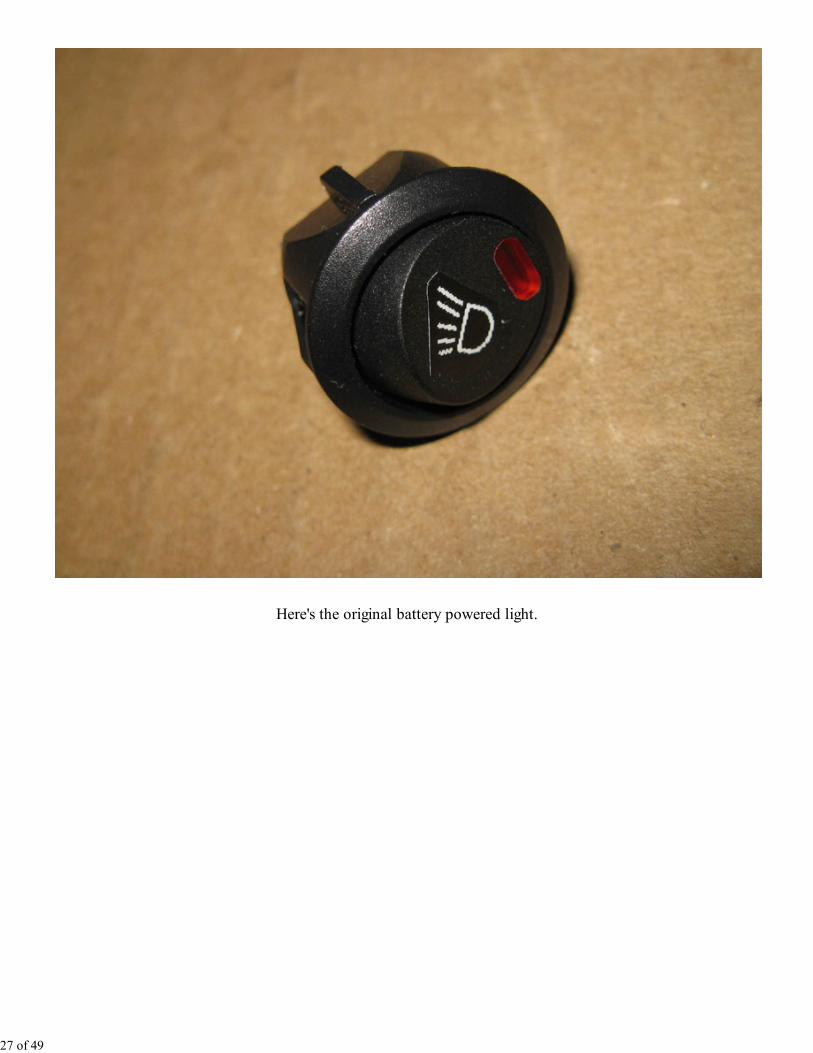
Here's the original battery powered light.
27 of 49
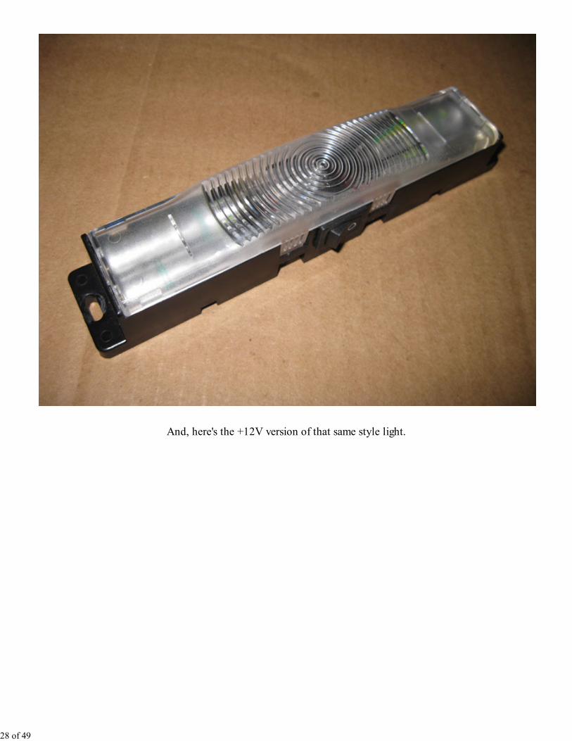
And, here's the +12V version of that same style light.
28 of 49
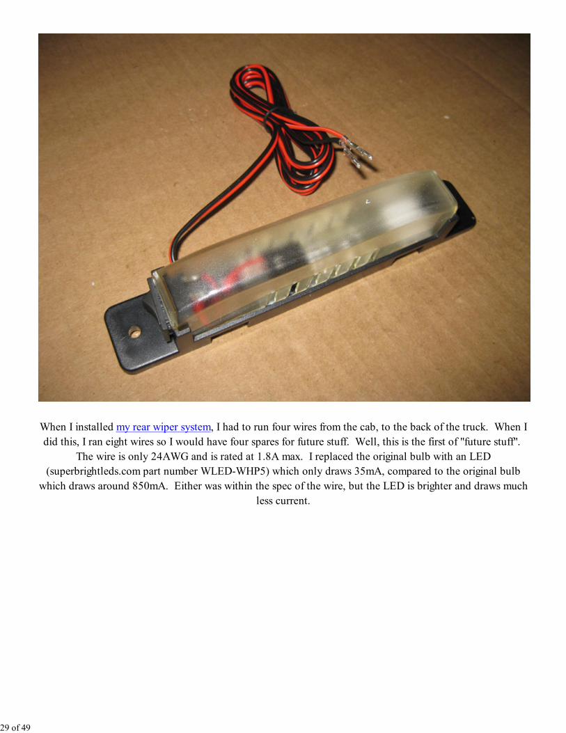
When I installed my rear wiper system, I had to run four wires from the cab, to the back of the truck. When I
did this, I ran eight wires so I would have four spares for future stuff. Well, this is the first of "future stuff".
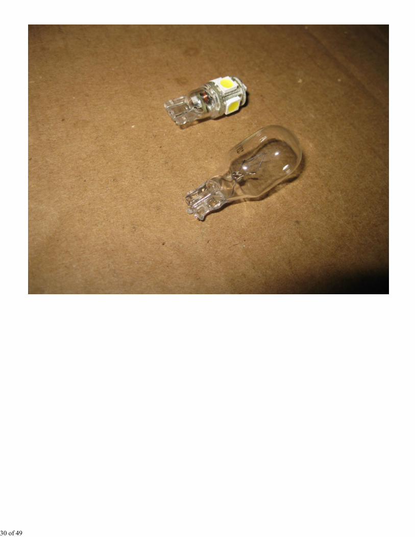
The wire is only 24AWG and is rated at 1.8A max. I replaced the original bulb with an LED
(superbrightleds.com part number WLED-WHP5) which only draws 35mA, compared to the original bulb
which draws around 850mA. Either was within the spec of the wire, but the LED is brighter and draws much
less current.
29 of 49
30 of 49
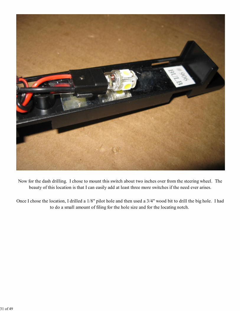
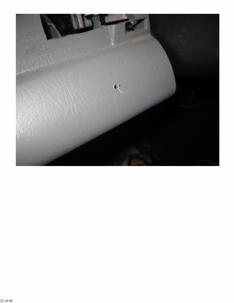
Now for the dash drilling. I chose to mount this switch about two inches over from the steering wheel. The
beauty of this location is that I can easily add at least three more switches if the need ever arises.
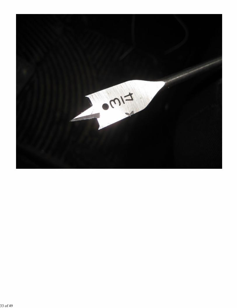
Once I chose the location, I drilled a 1/8" pilot hole and then used a 3/4" wood bit to drill the big hole. I had
to do a small amount of filing for the hole size and for the locating notch.
31 of 49
32 of 49
33 of 49
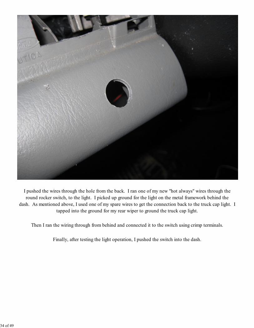
I pushed the wires through the hole from the back. I ran one of my new "hot always" wires through the
round rocker switch, to the light. I picked up ground for the light on the metal framework behind the
dash. As mentioned above, I used one of my spare wires to get the connection back to the truck cap light. I
tapped into the ground for my rear wiper to ground the truck cap light.
Then I ran the wiring through from behind and connected it to the switch using crimp terminals.
Finally, after testing the light operation, I pushed the switch into the dash.
34 of 49
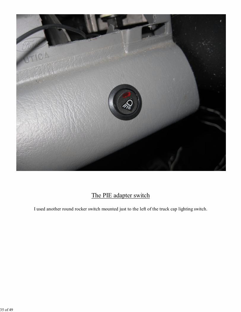
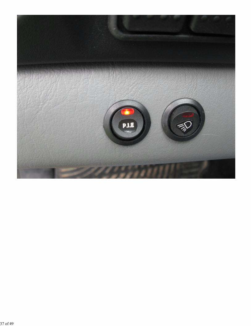
The PIE adapter switch
I used another round rocker switch mounted just to the left of the truck cap lighting switch.
35 of 49
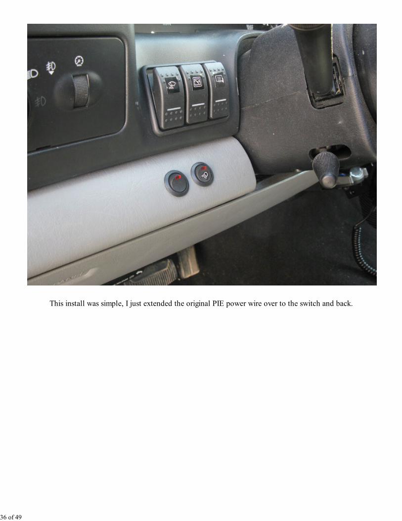
This install was simple, I just extended the original PIE power wire over to the switch and back.
36 of 49
37 of 49
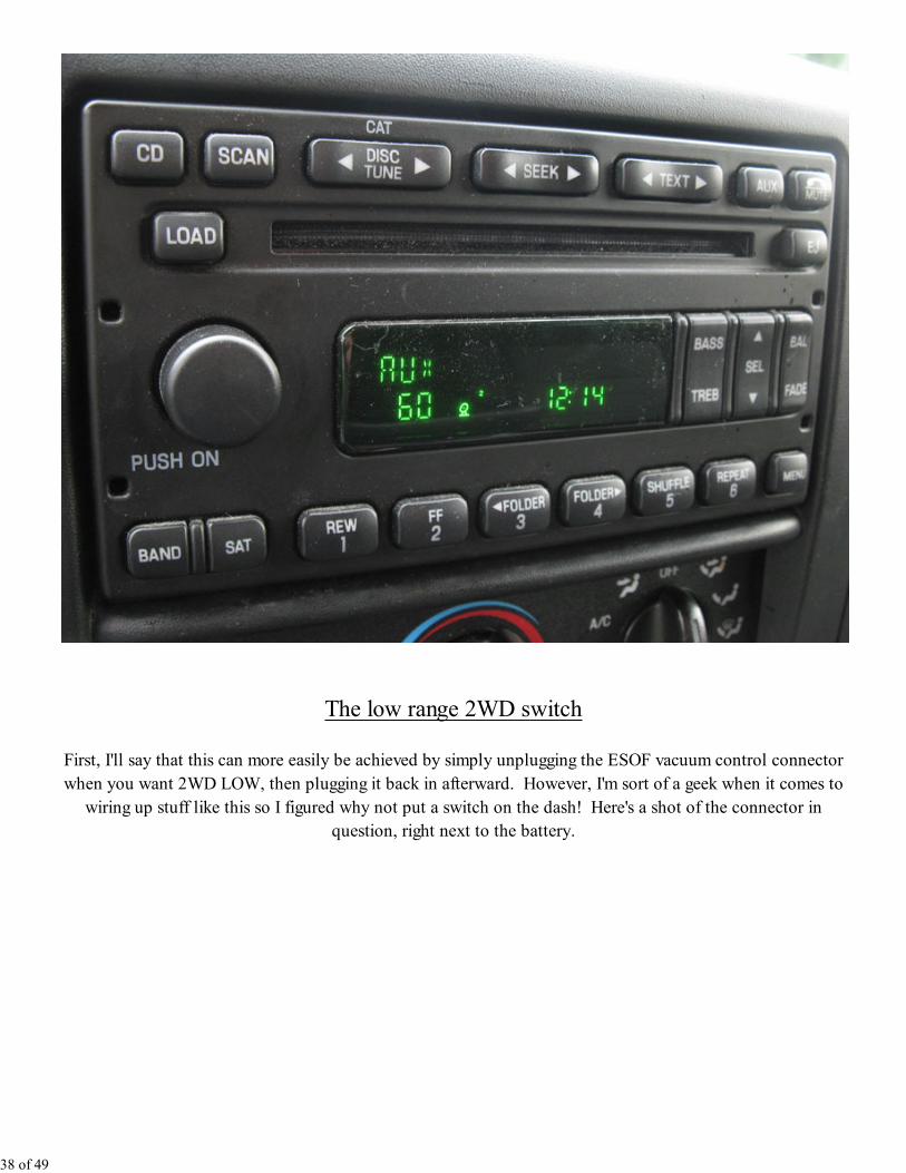
The low range 2WD switch
First, I'll say that this can more easily be achieved by simply unplugging the ESOF vacuum control connector
when you want 2WD LOW, then plugging it back in afterward. However, I'm sort of a geek when it comes to
wiring up stuff like this so I figured why not put a switch on the dash! Here's a shot of the connector in
question, right next to the battery.
38 of 49
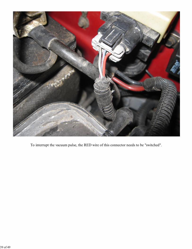
To interrupt the vacuum pulse, the RED wire of this connector needs to be "switched".
39 of 49
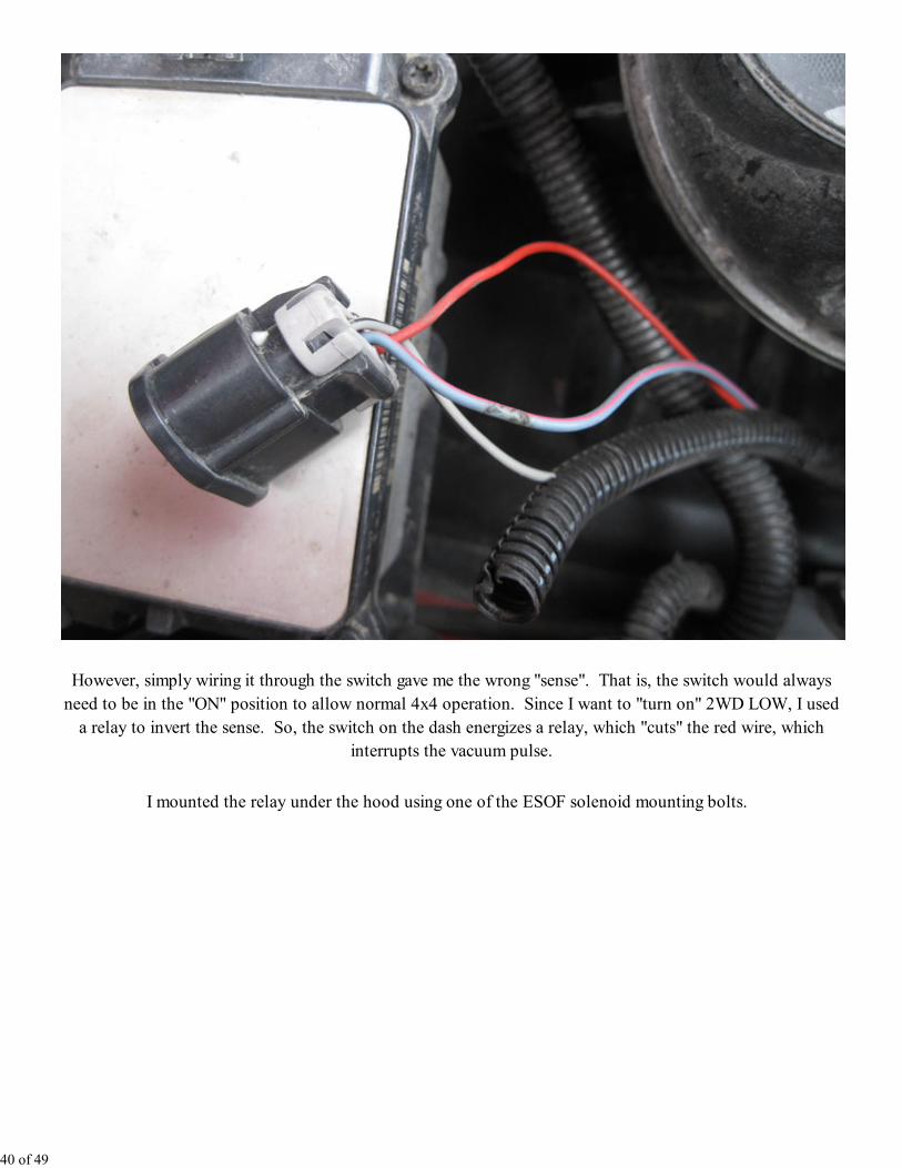
However, simply wiring it through the switch gave me the wrong "sense". That is, the switch would always
need to be in the "ON" position to allow normal 4x4 operation. Since I want to "turn on" 2WD LOW, I used
a relay to invert the sense. So, the switch on the dash energizes a relay, which "cuts" the red wire, which
interrupts the vacuum pulse.
I mounted the relay under the hood using one of the ESOF solenoid mounting bolts.
40 of 49
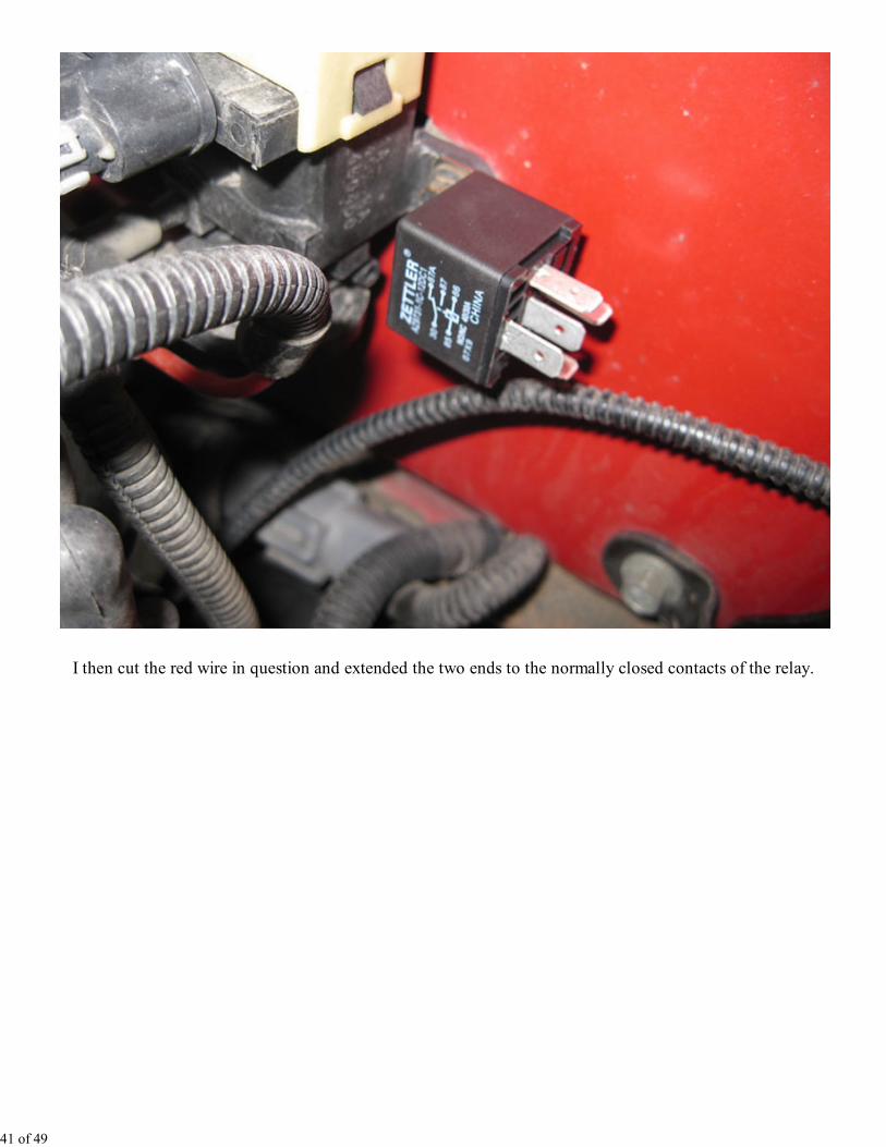
I then cut the red wire in question and extended the two ends to the normally closed contacts of the relay.
41 of 49
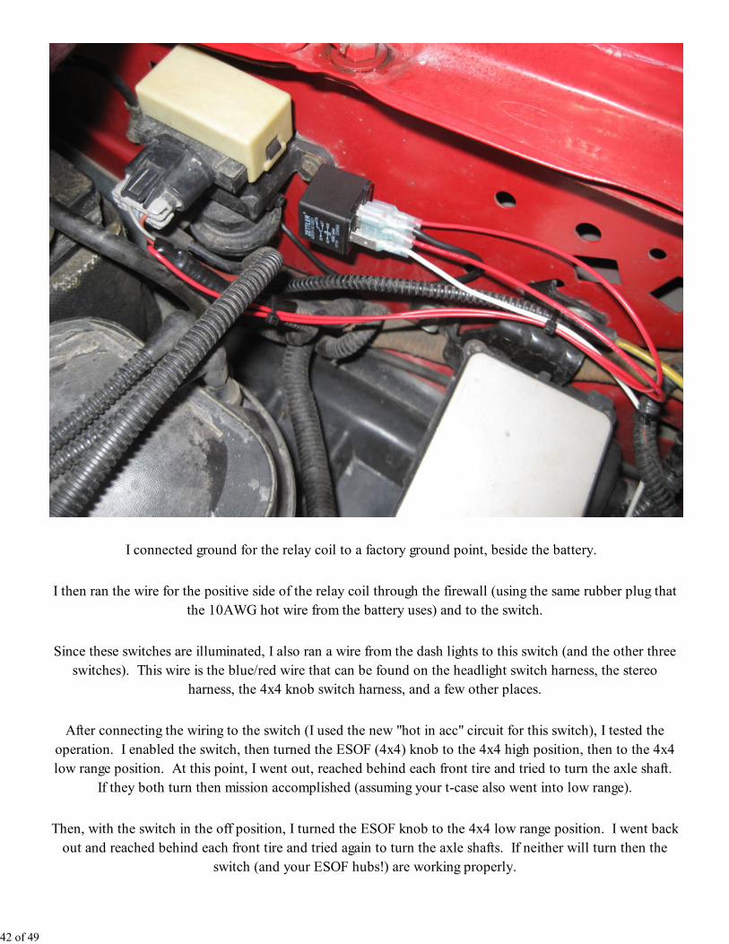
I connected ground for the relay coil to a factory ground point, beside the battery.
I then ran the wire for the positive side of the relay coil through the firewall (using the same rubber plug that
the 10AWG hot wire from the battery uses) and to the switch.
Since these switches are illuminated, I also ran a wire from the dash lights to this switch (and the other three
switches). This wire is the blue/red wire that can be found on the headlight switch harness, the stereo
harness, the 4x4 knob switch harness, and a few other places.
After connecting the wiring to the switch (I used the new "hot in acc" circuit for this switch), I tested the
operation. I enabled the switch, then turned the ESOF (4x4) knob to the 4x4 high position, then to the 4x4
low range position. At this point, I went out, reached behind each front tire and tried to turn the axle shaft.
If they both turn then mission accomplished (assuming your t-case also went into low range).
Then, with the switch in the off position, I turned the ESOF knob to the 4x4 low range position. I went back
out and reached behind each front tire and tried again to turn the axle shafts. If neither will turn then the
switch (and your ESOF hubs!) are working properly.
42 of 49

The Wiper Shaker switch
This is the normally open momentary switch, and I chose to mount it in the left-most slot of the three-switch
mount.
Then, I used my last remaining "customer use wire" through the firewall to get the power connection into the
cab.
I connected this wire through an inline fuse and then to the momentary switch. I also connected the dash
lighting wire and GND to the switch. I used the new "hot in acc" circuit for this switch.
To test this circuit, I connected my meter to the wire under the hood, hit the switch, and saw +12V. So, the
circuit is working, there's just nothing there to use it. I put a little heat shrink over the end of the wire until I
get the shaker kit.
Update Feb 2011 -- I finally bought the wiper shaker kit and installed it. I haven't had it long enough to
report how well it works, but when I do I'll put it in this write up:
Wiper Shaker Installation
The backup camera switch
This is the next switch in the three-switch mount. Under the dash I tapped into one of my spare wires going
to the back of the truck, and connected it through an inline fuse, to this switch. This is the same 24AWG
wiring mentioned above. To make sure the current draw was in a safe range, I used a clamp-on current meter
to measure the current draw when activated via the reverse lamps. I measured this to be around 150mA,
which is well under the 1.8A spec of the wire. I also connected the dash lighting, GND, and the "hot in acc"
for power to the switch.
Meanwhile, at the back of the truck, I picked up the other end of my spare wire and attached it to a diode.
The diode keeps voltage from back-feeding into the switch when the reverse lights are on. Similarly, I have a
diode in the reverse lamp signal to keep my new switched voltage from lighting up the reverse lights. See the
schematic above for details.
Next, I checked the circuit with my voltmeter. I was able to see +12V on that wire when I flipped the switch,
so I connected it up to the camera wire.
Testing this is also easy -- just flip the switch and make sure the backup camera display comes on. Then,
make sure that the reverse lights do not come on. Finally, turn on the camera with the reverse lights and
make sure the red indicator lamp on the switch doesn't come on. If it did come on, that would indicate that
voltage from the reverse lamp circuit was back-feeding into the switch. This would point to a wiring
43 of 49
problem, probably with the diode.
The mirror heat switch
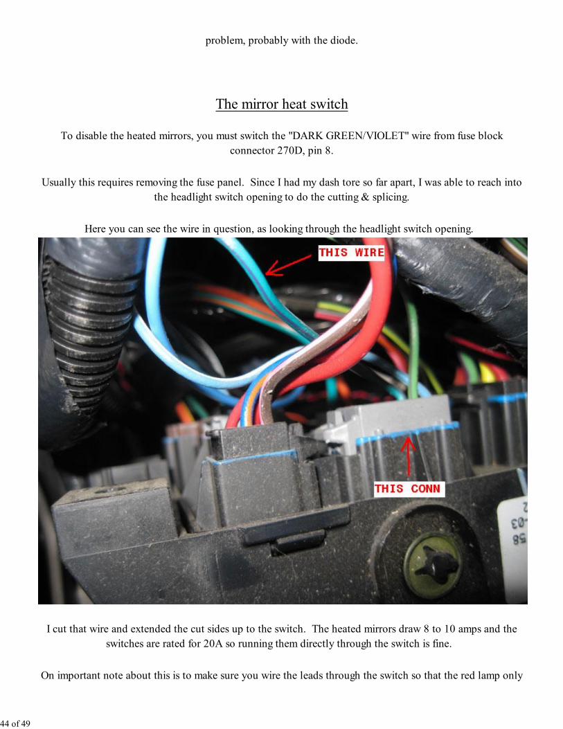
To disable the heated mirrors, you must switch the "DARK GREEN/VIOLET" wire from fuse block
connector 270D, pin 8.
Usually this requires removing the fuse panel. Since I had my dash tore so far apart, I was able to reach into
the headlight switch opening to do the cutting & splicing.
Here you can see the wire in question, as looking through the headlight switch opening.
I cut that wire and extended the cut sides up to the switch. The heated mirrors draw 8 to 10 amps and the
switches are rated for 20A so running them directly through the switch is fine.
On important note about this is to make sure you wire the leads through the switch so that the red lamp only
44 of 49
comes on when the switch is on. If you wire the "hot" side of the cut wire to pin #3 of the switch, the red
lamp will be on all the time, even though the mirror heat is disabled.
Before I started this install, I ran the truck for a few minutes, and measured the mirror temps with an IR
thermometer and watched the temp increase by about 5 deg F. After installing the switch, I ran the truck
again and after a few minutes, the mirror temps did not change. Then I flipped the switch and watched the
temps start increasing again.
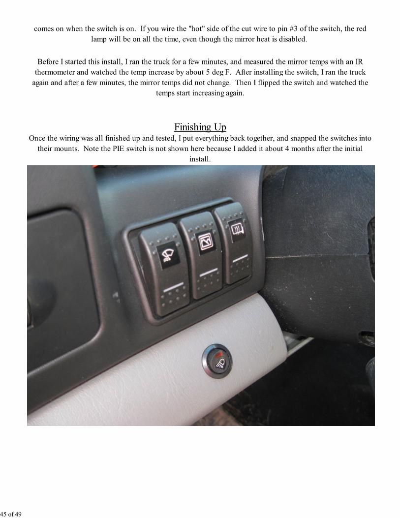
Finishing UpOnce the wiring was all finished up and tested, I put everything back together, and snapped the switches into
their mounts. Note the PIE switch is not shown here because I added it about 4 months after the initial
install.
45 of 49
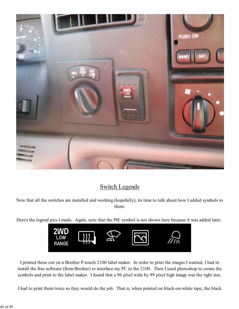
Switch Legends
Now that all the switches are installed and working (hopefully), its time to talk about how I added symbols to
them.
Here's the legend pics I made. Again, note that the PIE symbol is not shown here because it was added later.
I printed these out on a Brother P-touch 2100 label maker. In order to print the images I wanted, I had to
install the free software (from Brother) to interface my PC to the 2100. Then I used photoshop to create the
symbols and print to the label maker. I found that a 96 pixel wide by 99 pixel high image was the right size.
I had to print them twice so they would do the job. That is, when printed on black-on-white tape, the black
46 of 49
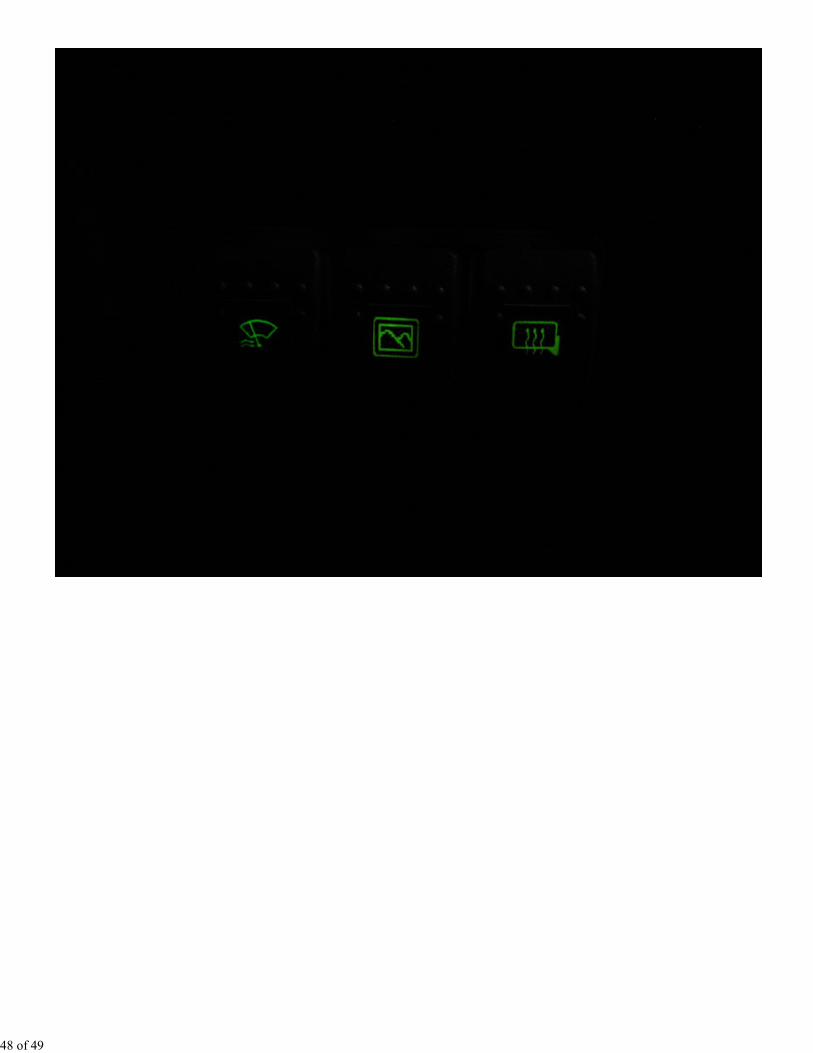
wasn't dark enough to block all of the green background. So, I printed a second label on black-on-clear tape
and over layed it onto the first label. This seems to work great.
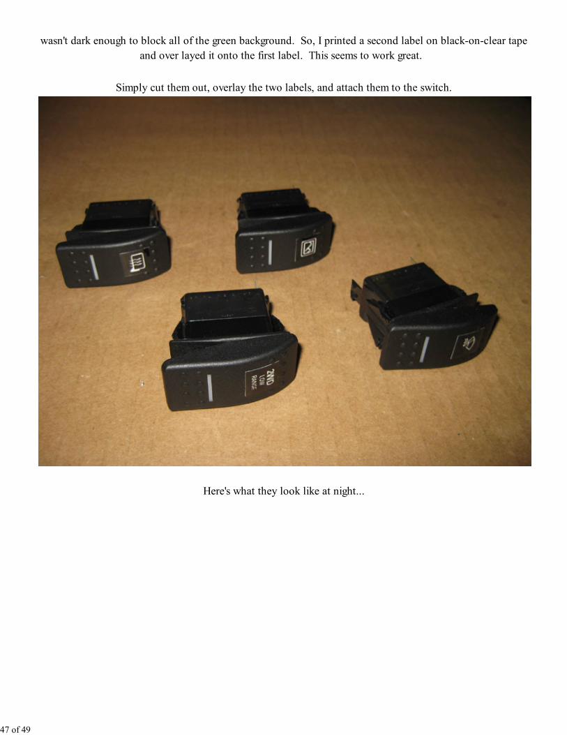
Simply cut them out, overlay the two labels, and attach them to the switch.
Here's what they look like at night...
47 of 49
48 of 49