Embed Size (px)
Citation preview
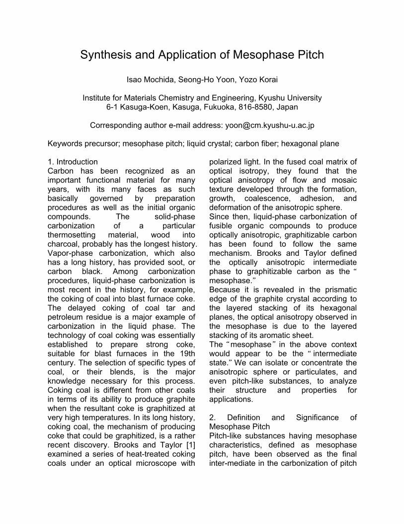
Synthesis and Application of Mesophase Pitch
Isao Mochida, Seong-Ho Yoon, Yozo Korai
Institute for Materials Chemistry and Engineering, Kyushu University 6-1 Kasuga-Koen, Kasuga, Fukuoka, 816-8580, Japan
Corresponding author e-mail address: [email protected]
Keywords precursor; mesophase pitch; liquid crystal; carbon fiber; hexagonal plane 1. Introduction Carbon has been recognized as an important functional material for many years, with its many faces as such basically governed by preparation procedures as well as the initial organic compounds. The solid-phase carbonization of a particular thermosetting material, wood into charcoal, probably has the longest history. Vapor-phase carbonization, which also has a long history, has provided soot, or carbon black. Among carbonization procedures, liquid-phase carbonization is most recent in the history, for example, the coking of coal into blast furnace coke. The delayed coking of coal tar and petroleum residue is a major example of carbonization in the liquid phase. The technology of coal coking was essentially established to prepare strong coke, suitable for blast furnaces in the 19th century. The selection of specific types of coal, or their blends, is the major knowledge necessary for this process. Coking coal is different from other coals in terms of its ability to produce graphite when the resultant coke is graphitized at very high temperatures. In its long history, coking coal, the mechanism of producing coke that could be graphitized, is a rather recent discovery. Brooks and Taylor [1] examined a series of heat-treated coking coals under an optical microscope with
polarized light. In the fused coal matrix of optical isotropy, they found that the optical anisotropy of flow and mosaic texture developed through the formation, growth, coalescence, adhesion, and deformation of the anisotropic sphere. Since then, liquid-phase carbonization of fusible organic compounds to produce optically anisotropic, graphitizable carbon has been found to follow the same mechanism. Brooks and Taylor defined the optically anisotropic intermediate phase to graphitizable carbon as the mesophase. Because it is revealed in the prismatic edge of the graphite crystal according to the layered stacking of its hexagonal planes, the optical anisotropy observed in the mesophase is due to the layered stacking of its aromatic sheet. The mesophase in the above context would appear to be the intermediate state. We can isolate or concentrate the anisotropic sphere or particulates, and even pitch-like substances, to analyze their structure and properties for applications. 2. Definition and Significance of Mesophase Pitch Pitch-like substances having mesophase characteristics, defined as mesophase pitch, have been observed as the final inter-mediate in the carbonization of pitch
into the semicoke of anisotropy. The mesophase pitch exhibits the optical anisotropy and fluidity to be micro- and nanoscopically deformable according to gas flow, static pressure, and shape of the container. Carbonaceous anisotropic material is separated from the isotropic matrix by a rather low-yield extraction. It is possible, but not easy, to separate mesophase pitch from the carbonation system, because heterogeneity of the pitch leads to various intermediate materials and to product carbons with variable properties during carbonization. The mesophase pitch is prepared by selecting a starting material and carbonization procedure with particular care, as described later. These are important steps in the preparation of mesophase-pitch-based carbon fiber. Mesophase pitch has been defined as a carbonaceous material of optical anisotropy, showing fusibility within a moderated temperature range. Such an optical anisotropy must be maintained in a fused state below the transition temperature. Hence, this pitch is a kind of liquid crystal material that shows both thermotropic and lyotropic properties. It also exhibits discotic liquid crystalline structural properties. Such liquid crystal properties of mesophase pitch occupy a particular position in the map of carbon manufacture, because of its characteristic graphitization and deformability, as well as a very high carbon value. Carbon fiber of high strength, modulus, and thermal conductivity is one of the major products now being developed. 3. Preparation of Mesophase Pitch 3.1 Heat Treatment of Pitches Ohtani[2] first prepared general-purpose, isotropic, pitch-based carbon fiber
through melt spinning, thermal stabilization, and carbonization of isotropic pitch soon after Polyacrylonitrile (PAN)-based carbon fiber was proposed by Shindo.[3] He then went on to prepare high modulus carbon fibers from particular pitch-like materials, such as tetrabenzophenazine, polyvinylchloride, and residues of cracked crude oil. At the time, he did not fully characterize these particular pitches. Later, such particular pitches were found to display a mesophase nature, although their softening points were rather high. The low melting point is very important, because condensation reactions may occur at a significant rate at spinning temperatures in the range of 380 to 430 °C. Consequently, the resultant mesophase pitch must be spun below 350 °C. Higher spinning temperatures cause successive polymerization and pyrolysis that change the properties of the mesophase pitch and result in unstable spinning. Barr et al. [4] developed an industrial process to produce mesophase pitch of facile spinnability, with a softening point below 300 °C, by heating the petroleum pitch under a vigorous purge stream of nitrogen. The nitrogen purge enhanced the removal of the volatile materials, with none, or less, of the reactivity and low molecular weight that form during the heat treatment of the isotropic phase to inhibit development of the mesophase. They claimed that the mesophase pitch thus produced exhibited many superior spinning properties in comparison with conventional, heat-soaked pitch without the vigorous purge. In a 1980 patent assigned to Exxon, extraction with two typical solvents was disclosed as a method of separating a mesophase from a petroleum-derived pitch mixture, by removing both the lightest and heaviest fractions. [5] More

recently, supercritical toluene has been used for this purpose. [6] Strehlow [7] first demonstrated the use of gravity to separate mesophase from the isotropic pitch matrix. He successfully generated mesophase pitch by using high-temperature centrifugation. Tonen [8] was the first to apply this process to the industrial preparation of mesophase pitch for carbon fiber production. Mochida et al. [9] found that naphthenic groups and short alkyl side chains in the mesogen molecules are essential if a mesophase pitch is to maintain the low softening point necessary for stable spinning and reasonable stabilization reactivity. Hence, mesophase pitch can be prepared from coal-tar pitch, but its softening point is relatively high and very non-reactive to oxidation. Before preparation of mesophase pitch, Yamada et al.[10] and Mochida et al.[11] hydrogenated the pre-cursor pitch to improve the properties of mesophase pitch by introducing naphthenic groups using a hydrogen donor solvent (e.g., tetra-hydroquinone) and catalytic hydrogenation, respectively. Some of the introduced naphthenic groups remained in the mesophase pitch at the stabilization stage. Park and Mochida [12] proposed a two-stage process for the production of mesophase pitch. In the first stage, mesogen molecules were formed under pressure at high temperature. In the second stage, these molecules were efficiently and rapidly concentrated under vacuum. A significant part of the light fraction could be converted into mesogen molecules under pressure, increasing the yield of mesophase pitch. Overall efforts to improve the yield and quality of mesophase pitches from residues cannot overcome the restrictions ascribed to a complex mixture of a variety
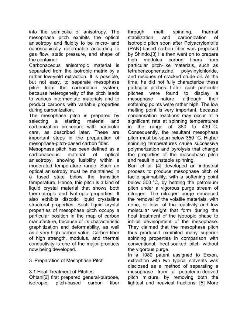
of hydrocarbon species with variable reactivities and thermal activation processes. Besides, fine particles of nanometer-size solid contaminants, such as free carbon/coke, catalysts, and mineral particles, usually found in the residues should be reduced to less than 10 ppm. Such a level of purification is very costly. 3.2 Synthetic Methods of Preparing Mesophase Pitch Mochida et al. [13] found that a precursor pitch for spinnable mesophase pitch can be prepared from naphthalene and ethylene tar using aluminum chloride as catalyst. After removal of the catalyst, the precursor pitch was further heat-treated to mesophase pitch, which still carried significant amounts of naphthenic groups, and exhibited a low softening point and high solubility in comparison to that prepared via the thermal process. The problem is due to the remaining solid aluminum hydroxide and alumina, which are very difficult to remove completely. Repeated use of AlCl3 is almost impossible. Mochida et al. [14], [15] and Korai et al. [16] reported that a spinnable mesophase pitch could be effectively produced from aromatic hydrocarbons using HF/BF3 as a condensation catalyst. HF/BF3, which has been used as a Friedel-Craft super acid catalyst, produces the protonated complexes of aromatic hydrocarbons such as naphthalene, as shown in Figure 1. This complex attacks the second aromatic molecule at the position of the largest basicity to produce a dimer with two naphthenic hydrogens. Such reactions repeat to produce oligomers of trimers to decamers with a yield above 90 wt%. Because HF and BF3 have boiling points of 19.9 and -101.1 °C, respectively, the catalyst can easily be recovered from
the pitch by atmospheric distillation and then be recycled. This process has been commercialized as described below.
Figure 1. Model for catalytic condensation of aromatic hydrocarbons with HF/BF3. Yanagida et al. [17] reported that mesophase pitch could be produced from C9 alkyl-benzene in naphtha by condensation with formaldehyde followed by successive heat treatments. Alkyl-benzene was coupled by CH2 linkages to form ladder-like oligomers that were thermally dehydrogenated and condensed into keto-type aromatic hydrocarbons. Some methyl groups remain on the ring. Several bends in the aromatic skeleton are believed to be present.[18] Such a unique structure for mesophase pitch leads to unusually low softening points, a low melt viscosity, and highly ordered stacking in the spun fiber. A major problem with this method is its cost. 3.3 Commercial Preparation Japan Graphite Fiber (joint venture of Nippon Steel and Nippon Oil), Mitsubishi Chemical, and Maruzen commercialized mesophase pitch from coal tar by the thermal process described above. Mitsubishi Gas Chemical Company (MGC) constructed a commercial-base facility (1500 t/year) of naphthalene-derived mesophase pitch using HF/BF3
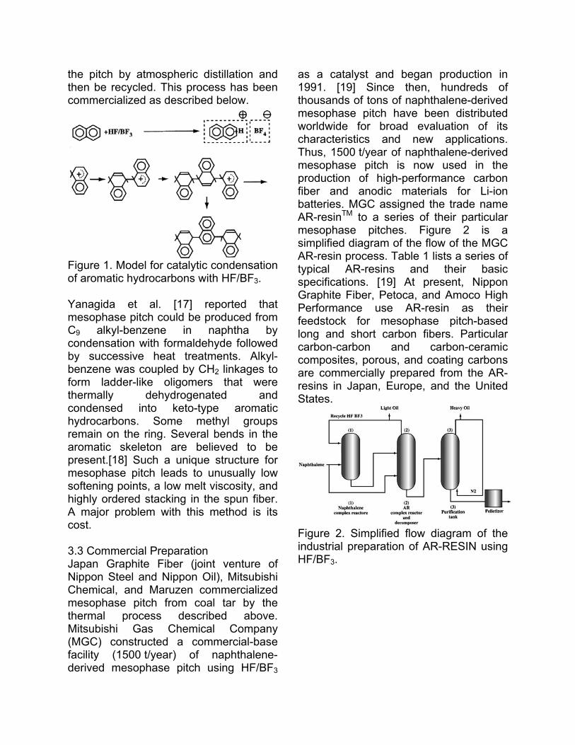
as a catalyst and began production in 1991. [19] Since then, hundreds of thousands of tons of naphthalene-derived mesophase pitch have been distributed worldwide for broad evaluation of its characteristics and new applications. Thus, 1500 t/year of naphthalene-derived mesophase pitch is now used in the production of high-performance carbon fiber and anodic materials for Li-ion batteries. MGC assigned the trade name AR-resinTM to a series of their particular mesophase pitches. Figure 2 is a simplified diagram of the flow of the MGC AR-resin process. Table 1 lists a series of typical AR-resins and their basic specifications. [19] At present, Nippon Graphite Fiber, Petoca, and Amoco High Performance use AR-resin as their feedstock for mesophase pitch-based long and short carbon fibers. Particular carbon-carbon and carbon-ceramic composites, porous, and coating carbons are commercially prepared from the AR-resins in Japan, Europe, and the United States.
Figure 2. Simplified flow diagram of the industrial preparation of AR-RESIN using HF/BF3.
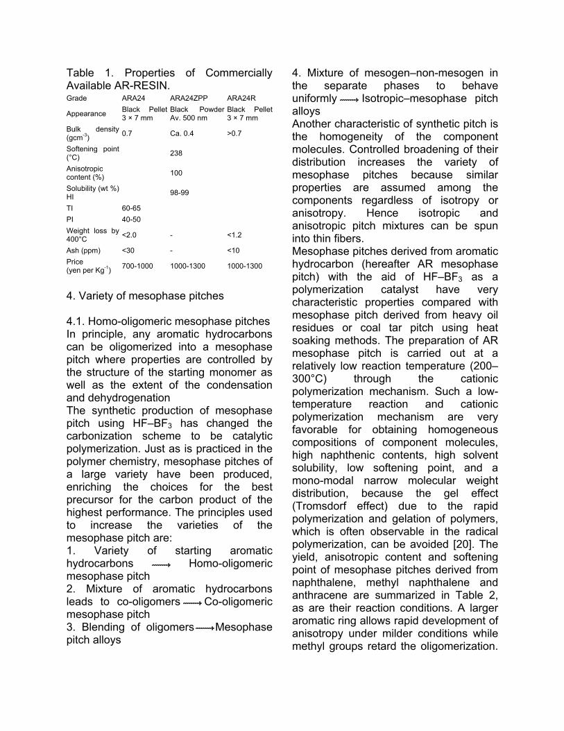
Table 1. Properties of Commercially Available AR-RESIN. Grade ARA24 ARA24ZPP ARA24R
Appearance Black Pellet 3 × 7 mm
Black Powder Av. 500 nm
Black Pellet 3 × 7 mm
Bulk density (gcm-3) 0.7 Ca. 0.4 >0.7
Softening point (°C) 238
Anisotropic content (%) 100
Solubility (wt %) HI 98-99
TI 60-65 PI 40-50 Weight loss by 400°C <2.0 - <1.2
Ash (ppm) <30 - <10 Price (yen per Kg-1) 700-1000 1000-1300 1000-1300
4. Variety of mesophase pitches 4.1. Homo-oligomeric mesophase pitches In principle, any aromatic hydrocarbons can be oligomerized into a mesophase pitch where properties are controlled by the structure of the starting monomer as well as the extent of the condensation and dehydrogenation The synthetic production of mesophase pitch using HF�BF3 has changed the carbonization scheme to be catalytic polymerization. Just as is practiced in the polymer chemistry, mesophase pitches of a large variety have been produced, enriching the choices for the best precursor for the carbon product of the highest performance. The principles used to increase the varieties of the mesophase pitch are: 1. Variety of starting aromatic hydrocarbons Homo-oligomeric mesophase pitch 2. Mixture of aromatic hydrocarbons leads to co-oligomers Co-oligomeric mesophase pitch 3. Blending of oligomers Mesophase pitch alloys
4. Mixture of mesogen�non-mesogen in the separate phases to behave uniformly Isotropic�mesophase pitch alloys Another characteristic of synthetic pitch is the homogeneity of the component molecules. Controlled broadening of their distribution increases the variety of mesophase pitches because similar properties are assumed among the components regardless of isotropy or anisotropy. Hence isotropic and anisotropic pitch mixtures can be spun into thin fibers. Mesophase pitches derived from aromatic hydrocarbon (hereafter AR mesophase pitch) with the aid of HF�BF3 as a polymerization catalyst have very characteristic properties compared with mesophase pitch derived from heavy oil residues or coal tar pitch using heat soaking methods. The preparation of AR mesophase pitch is carried out at a relatively low reaction temperature (200�300°C) through the cationic polymerization mechanism. Such a low-temperature reaction and cationic polymerization mechanism are very favorable for obtaining homogeneous compositions of component molecules, high naphthenic contents, high solvent solubility, low softening point, and a mono-modal narrow molecular weight distribution, because the gel effect (Tromsdorf effect) due to the rapid polymerization and gelation of polymers, which is often observable in the radical polymerization, can be avoided [20]. The yield, anisotropic content and softening point of mesophase pitches derived from naphthalene, methyl naphthalene and anthracene are summarized in Table 2, as are their reaction conditions. A larger aromatic ring allows rapid development of anisotropy under milder conditions while methyl groups retard the oligomerization.

The mesophase pitch derived from methylnaphthalene contains more methyl groups and fewer naphthenes. The methyl groups on the mesogen molecules exert a profound influence on the properties of the mesophase pitch.
Table 2. Preparation conditions of pitches and some of their properties
Edie et al. reported that AR mesophase pitch derived from methylnaphthalene showed better spinnability but more temperature dependence in its melt-viscosity than a heat-soaked one [21]. Yoon et al. reported that pitch fiber from AR pitches (both methylnaphthalene and naphthalene-derived mesophase pitches) showed higher oxidation reactivity to shorten the stabilization time required [22]. Their active sites for oxidation appear different. A larger variety of aryl- and phenyl-substituted naphthalene pitches was expected to exhibit different nature and properties. HF�BF3 can also polymerize nitrogen-containing aromatic compounds. The reaction schemes for quinoline- and isoquinoline-derived pitches are illustrated in Figure 3. Flow domain texture prevailed in the coke from quinoline while isoquinoline formed a very fine mosaic texture [23]. Quinoline-derived pitch retained nitrogen, hydrogen, and ring structures, leading to many naphthenic groups in the oligomers. The full condensation of aromatic rings
appears rather less, oligomers of aryl�aryl bonds being the major components. A longer reaction time and/or higher reaction temperature increased the yield of the pitch increasing the insoluble fraction of larger molecular weight, and producing more quinoline units by maintaining basically the above structural characteristics. In contrast, isoquinoline lost considerable amounts of nitrogen and hydrogen during the oligomerization, and hence a significant degradation of its aromatic rings is suggested. Both nitrogen as well as carbon in quinoline can be cationic, forming oligomers with a high yield, while the cationic intermediate from isoquinoline loses nitrogen as NH3 through the C�N bond fission induced by the reactive naphthenic hydrogens, and reduces the pitch yield. The latter reaction removes both nitrogen and naphthenic hydrogen, leading to early solidification due to the highly aromatic structure. Sulfur- and oxygen-containing heterocyclic compounds can also be used as the starting monomers for mesophase pitched with specified heterocyclic functions.
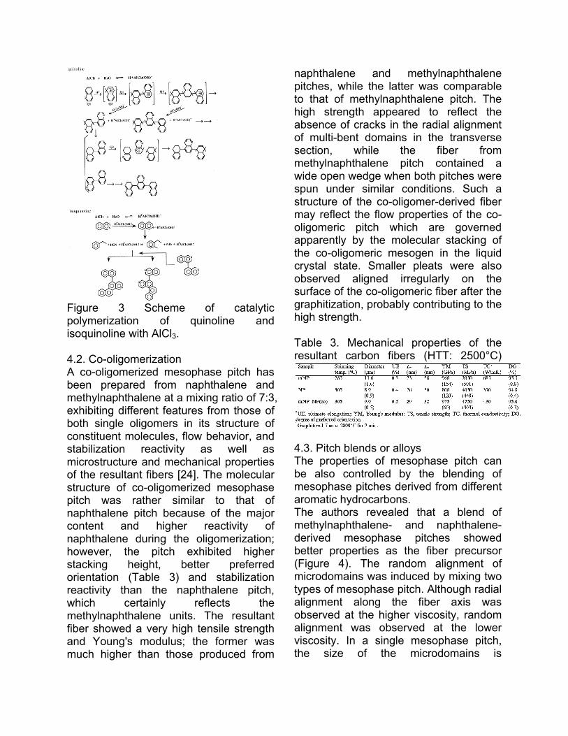
Figure 3 Scheme of catalytic polymerization of quinoline and isoquinoline with AlCl3. 4.2. Co-oligomerization A co-oligomerized mesophase pitch has been prepared from naphthalene and methylnaphthalene at a mixing ratio of 7:3, exhibiting different features from those of both single oligomers in its structure of constituent molecules, flow behavior, and stabilization reactivity as well as microstructure and mechanical properties of the resultant fibers [24]. The molecular structure of co-oligomerized mesophase pitch was rather similar to that of naphthalene pitch because of the major content and higher reactivity of naphthalene during the oligomerization; however, the pitch exhibited higher stacking height, better preferred orientation (Table 3) and stabilization reactivity than the naphthalene pitch, which certainly reflects the methylnaphthalene units. The resultant fiber showed a very high tensile strength and Young's modulus; the former was much higher than those produced from
naphthalene and methylnaphthalene pitches, while the latter was comparable to that of methylnaphthalene pitch. The high strength appeared to reflect the absence of cracks in the radial alignment of multi-bent domains in the transverse section, while the fiber from methylnaphthalene pitch contained a wide open wedge when both pitches were spun under similar conditions. Such a structure of the co-oligomer-derived fiber may reflect the flow properties of the co-oligomeric pitch which are governed apparently by the molecular stacking of the co-oligomeric mesogen in the liquid crystal state. Smaller pleats were also observed aligned irregularly on the surface of the co-oligomeric fiber after the graphitization, probably contributing to the high strength. Table 3. Mechanical properties of the resultant carbon fibers (HTT: 2500°C)
4.3. Pitch blends or alloys The properties of mesophase pitch can be also controlled by the blending of mesophase pitches derived from different aromatic hydrocarbons. The authors revealed that a blend of methylnaphthalene- and naphthalene-derived mesophase pitches showed better properties as the fiber precursor (Figure 4). The random alignment of microdomains was induced by mixing two types of mesophase pitch. Although radial alignment along the fiber axis was observed at the higher viscosity, random alignment was observed at the lower viscosity. In a single mesophase pitch, the size of the microdomains is
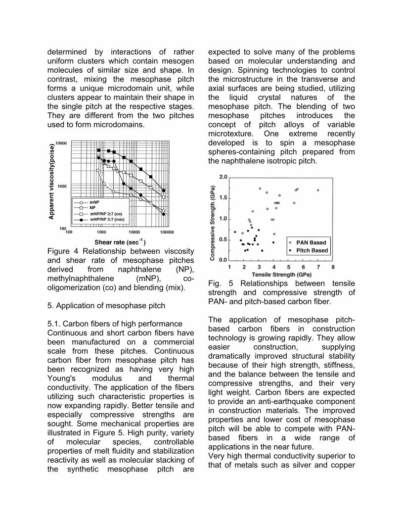
determined by interactions of rather uniform clusters which contain mesogen molecules of similar size and shape. In contrast, mixing the mesophase pitch forms a unique microdomain unit, while clusters appear to maintain their shape in the single pitch at the respective stages. They are different from the two pitches used to form microdomains.
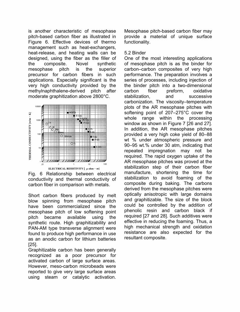
Figure 4 Relationship between viscosity and shear rate of mesophase pitches derived from naphthalene (NP), methylnaphthalene (mNP), co-oligomerization (co) and blending (mix). 5. Application of mesophase pitch 5.1. Carbon fibers of high performance Continuous and short carbon fibers have been manufactured on a commercial scale from these pitches. Continuous carbon fiber from mesophase pitch has been recognized as having very high Young's modulus and thermal conductivity. The application of the fibers utilizing such characteristic properties is now expanding rapidly. Better tensile and especially compressive strengths are sought. Some mechanical properties are illustrated in Figure 5. High purity, variety of molecular species, controllable properties of melt fluidity and stabilization reactivity as well as molecular stacking of the synthetic mesophase pitch are
expected to solve many of the problems based on molecular understanding and design. Spinning technologies to control the microstructure in the transverse and axial surfaces are being studied, utilizing the liquid crystal natures of the mesophase pitch. The blending of two mesophase pitches introduces the concept of pitch alloys of variable microtexture. One extreme recently developed is to spin a mesophase spheres-containing pitch prepared from the naphthalene isotropic pitch.
Fig. 5 Relationships between tensile strength and compressive strength of PAN- and pitch-based carbon fiber. The application of mesophase pitch-based carbon fibers in construction technology is growing rapidly. They allow easier construction, supplying dramatically improved structural stability because of their high strength, stiffness, and the balance between the tensile and compressive strengths, and their very light weight. Carbon fibers are expected to provide an anti-earthquake component in construction materials. The improved properties and lower cost of mesophase pitch will be able to compete with PAN-based fibers in a wide range of applications in the near future. Very high thermal conductivity superior to that of metals such as silver and copper
is another characteristic of mesophase pitch-based carbon fiber as illustrated in Figure 6. Effective devices of thermo management such as heat-exchangers, heat-release, and heating walls can be designed, using the fiber as the filler of the composite. Novel synthetic mesophase pitch is the superior precursor for carbon fibers in such applications. Especially significant is the very high conductivity provided by the methylnaphthalene-derived pitch after moderate graphitization above 2800°C.
Fig. 6 Relationship between electrical conductivity and thermal conductivity of carbon fiber in comparison with metals. Short carbon fibers produced by melt blow spinning from mesophase pitch have been commercialized since the mesophase pitch of low softening point pitch became available using the synthetic route. High graphitizability and PAN-AM type transverse alignment were found to produce high performance in use as an anodic carbon for lithium batteries [25]. Graphitizable carbon has been generally recognized as a poor precursor for activated carbon of large surface areas. However, meso-carbon microbeads were reported to give very large surface areas using steam or catalytic activation.
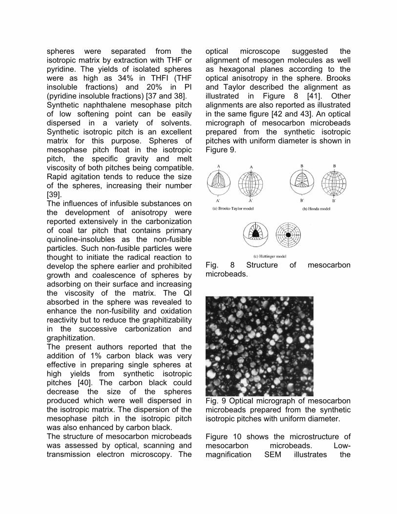
Mesophase pitch-based carbon fiber may provide a material of unique surface functionality. 5.2 Binder One of the most interesting applications of mesophase pitch is as the binder for carbon�carbon composites of very high performance. The preparation involves a series of processes, including injection of the binder pitch into a two-dimensional carbon fiber preform, oxidative stabilization, and successive carbonization. The viscosity�temperature plots of the AR mesophase pitches with softening point of 207�275°C cover the whole range within the processing window as shown in Figure 7 [26 and 27]. In addition, the AR mesophase pitches provided a very high coke yield of 80�88 wt % under atmospheric pressure and 90�95 wt.% under 30 atm, indicating that repeated impregnation may not be required. The rapid oxygen uptake of the AR mesophase pitches was proved at the stabilization step of their carbon fiber manufacture, shortening the time for stabilization to avoid foaming of the composite during baking. The carbons derived from the mesophase pitches were optically anisotropic with large domains and graphitizable. The size of the block could be controlled by the addition of phenolic resin and carbon black if required [27 and 28]. Such additives were effective in reducing the foaming. Thus, a high mechanical strength and oxidation resistance are also expected for the resultant composite.
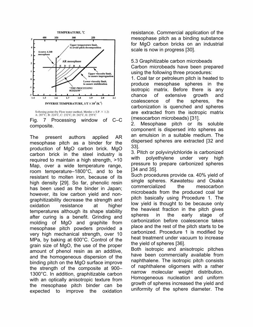
Fig. 7 Processing window of C�C composite. The present authors applied AR mesophase pitch as a binder for the production of MgO carbon brick. MgO carbon brick in the steel industry is required to maintain a high strength, >10 Map, over a wide temperature range, room temperature�1800°C, and to be resistant to molten iron, because of its high density [29]. So far, phenolic resin has been used as the binder in Japan; however, its low carbon yield and non-graphitizability decrease the strength and oxidation resistance at higher temperatures although its shape stability after curing is a benefit. Grinding and molding of MgO and graphite from mesophase pitch powders provided a very high mechanical strength, over 10 MPa, by baking at 600°C. Control of the grain size of MgO, the use of the proper amount of phenol resin as an additive, and the homogeneous dispersion of the binding pitch on the MgO surface improve the strength of the composite at 900�1300°C. In addition, graphitizable carbon with an optically anisotropic texture from the mesophase pitch binder can be expected to improve the oxidation
resistance. Commercial application of the mesophase pitch as a binding substance for MgO carbon bricks on an industrial scale is now in progress [30]. 5.3 Graphitizable carbon microbeads Carbon microbeads have been prepared using the following three procedures: 1. Coal tar or petroleum pitch is heated to produce mesophase spheres in the isotropic matrix. Before there is any chance of extensive growth and coalescence of the spheres, the carbonization is quenched and spheres are extracted from the isotropic matrix (mesocarbon microbeads) [31]. 2. Mesophase pitch or its soluble component is dispersed into spheres as an emulsion in a suitable medium. The dispersed spheres are extracted [32 and 33]. 3. Pitch or polyvinylchloride is carbonized with polyethylene under very high pressure to prepare carbonized spheres [34 and 35]. Such procedures provide ca. 40% yield of single spheres. Kawatetsu and Osaka commercialized the mesocarbon microbeads from the produced coal tar pitch basically using Procedure 1. The low yield is thought to be because only the heaviest fraction in the pitch gives spheres in the early stage of carbonization before coalescence takes place and the rest of the pitch starts to be carbonized. Procedure 1 is modified by heat treatment under vacuum to increase the yield of spheres [36]. Both isotropic and anisotropic pitches have been commercially available from naphthalene. The isotropic pitch consists of naphthalene oligomers with a rather narrow molecular weight distribution. Homogeneous nucleation and uniform growth of spheres increased the yield and uniformity of the sphere diameter. The
spheres were separated from the isotropic matrix by extraction with THF or pyridine. The yields of isolated spheres were as high as 34% in THFI (THF insoluble fractions) and 20% in PI (pyridine insoluble fractions) [37 and 38]. Synthetic naphthalene mesophase pitch of low softening point can be easily dispersed in a variety of solvents. Synthetic isotropic pitch is an excellent matrix for this purpose. Spheres of mesophase pitch float in the isotropic pitch, the specific gravity and melt viscosity of both pitches being compatible. Rapid agitation tends to reduce the size of the spheres, increasing their number [39]. The influences of infusible substances on the development of anisotropy were reported extensively in the carbonization of coal tar pitch that contains primary quinoline-insolubles as the non-fusible particles. Such non-fusible particles were thought to initiate the radical reaction to develop the sphere earlier and prohibited growth and coalescence of spheres by adsorbing on their surface and increasing the viscosity of the matrix. The QI absorbed in the sphere was revealed to enhance the non-fusibility and oxidation reactivity but to reduce the graphitizability in the successive carbonization and graphitization. The present authors reported that the addition of 1% carbon black was very effective in preparing single spheres at high yields from synthetic isotropic pitches [40]. The carbon black could decrease the size of the spheres produced which were well dispersed in the isotropic matrix. The dispersion of the mesophase pitch in the isotropic pitch was also enhanced by carbon black. The structure of mesocarbon microbeads was assessed by optical, scanning and transmission electron microscopy. The
optical microscope suggested the alignment of mesogen molecules as well as hexagonal planes according to the optical anisotropy in the sphere. Brooks and Taylor described the alignment as illustrated in Figure 8 [41]. Other alignments are also reported as illustrated in the same figure [42 and 43]. An optical micrograph of mesocarbon microbeads prepared from the synthetic isotropic pitches with uniform diameter is shown in Figure 9.
Fig. 8 Structure of mesocarbon microbeads.
Fig. 9 Optical micrograph of mesocarbon microbeads prepared from the synthetic isotropic pitches with uniform diameter. Figure 10 shows the microstructure of mesocarbon microbeads. Low-magnification SEM illustrates the
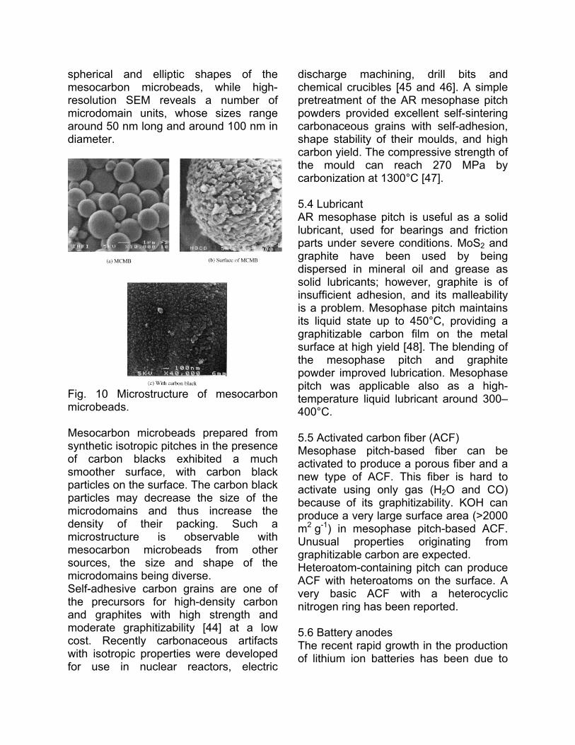
spherical and elliptic shapes of the mesocarbon microbeads, while high-resolution SEM reveals a number of microdomain units, whose sizes range around 50 nm long and around 100 nm in diameter.
Fig. 10 Microstructure of mesocarbon microbeads. Mesocarbon microbeads prepared from synthetic isotropic pitches in the presence of carbon blacks exhibited a much smoother surface, with carbon black particles on the surface. The carbon black particles may decrease the size of the microdomains and thus increase the density of their packing. Such a microstructure is observable with mesocarbon microbeads from other sources, the size and shape of the microdomains being diverse. Self-adhesive carbon grains are one of the precursors for high-density carbon and graphites with high strength and moderate graphitizability [44] at a low cost. Recently carbonaceous artifacts with isotropic properties were developed for use in nuclear reactors, electric
discharge machining, drill bits and chemical crucibles [45 and 46]. A simple pretreatment of the AR mesophase pitch powders provided excellent self-sintering carbonaceous grains with self-adhesion, shape stability of their moulds, and high carbon yield. The compressive strength of the mould can reach 270 MPa by carbonization at 1300°C [47]. 5.4 Lubricant AR mesophase pitch is useful as a solid lubricant, used for bearings and friction parts under severe conditions. MoS2 and graphite have been used by being dispersed in mineral oil and grease as solid lubricants; however, graphite is of insufficient adhesion, and its malleability is a problem. Mesophase pitch maintains its liquid state up to 450°C, providing a graphitizable carbon film on the metal surface at high yield [48]. The blending of the mesophase pitch and graphite powder improved lubrication. Mesophase pitch was applicable also as a high-temperature liquid lubricant around 300�400°C. 5.5 Activated carbon fiber (ACF) Mesophase pitch-based fiber can be activated to produce a porous fiber and a new type of ACF. This fiber is hard to activate using only gas (H2O and CO) because of its graphitizability. KOH can produce a very large surface area (>2000 m2 g-1) in mesophase pitch-based ACF. Unusual properties originating from graphitizable carbon are expected. Heteroatom-containing pitch can produce ACF with heteroatoms on the surface. A very basic ACF with a heterocyclic nitrogen ring has been reported. 5.6 Battery anodes The recent rapid growth in the production of lithium ion batteries has been due to
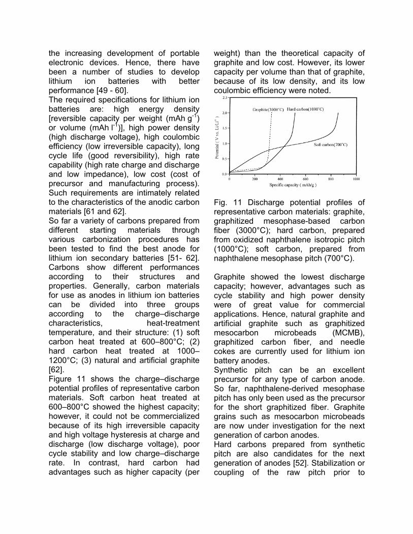
the increasing development of portable electronic devices. Hence, there have been a number of studies to develop lithium ion batteries with better performance [49 - 60]. The required specifications for lithium ion batteries are: high energy density [reversible capacity per weight (mAh g-1) or volume (mAh l-1)], high power density (high discharge voltage), high coulombic efficiency (low irreversible capacity), long cycle life (good reversibility), high rate capability (high rate charge and discharge and low impedance), low cost (cost of precursor and manufacturing process). Such requirements are intimately related to the characteristics of the anodic carbon materials [61 and 62]. So far a variety of carbons prepared from different starting materials through various carbonization procedures has been tested to find the best anode for lithium ion secondary batteries [51- 62]. Carbons show different performances according to their structures and properties. Generally, carbon materials for use as anodes in lithium ion batteries can be divided into three groups according to the charge�discharge characteristics, heat-treatment temperature, and their structure: (1) soft carbon heat treated at 600�800°C; (2) hard carbon heat treated at 1000�1200°C; (3) natural and artificial graphite [62]. Figure 11 shows the charge�discharge potential profiles of representative carbon materials. Soft carbon heat treated at 600�800°C showed the highest capacity; however, it could not be commercialized because of its high irreversible capacity and high voltage hysteresis at charge and discharge (low discharge voltage), poor cycle stability and low charge�discharge rate. In contrast, hard carbon had advantages such as higher capacity (per
weight) than the theoretical capacity of graphite and low cost. However, its lower capacity per volume than that of graphite, because of its low density, and its low coulombic efficiency were noted.
Fig. 11 Discharge potential profiles of representative carbon materials: graphite, graphitized mesophase-based carbon fiber (3000°C); hard carbon, prepared from oxidized naphthalene isotropic pitch (1000°C); soft carbon, prepared from naphthalene mesophase pitch (700°C). Graphite showed the lowest discharge capacity; however, advantages such as cycle stability and high power density were of great value for commercial applications. Hence, natural graphite and artificial graphite such as graphitized mesocarbon microbeads (MCMB), graphitized carbon fiber, and needle cokes are currently used for lithium ion battery anodes. Synthetic pitch can be an excellent precursor for any type of carbon anode. So far, naphthalene-derived mesophase pitch has only been used as the precursor for the short graphitized fiber. Graphite grains such as mesocarbon microbeads are now under investigation for the next generation of carbon anodes. Hard carbons prepared from synthetic pitch are also candidates for the next generation of anodes [52]. Stabilization or coupling of the raw pitch prior to
preparation converts the pitch to precursors for hard carbon anodes. A variety of aromatic ring systems are very attractive for preparing hard carbons of designed structure. Carbons prepared from heteroatom-containing pitch have unique sites for lithium ions. This is the atomic defect in the hexagonal plane due to the evolution of heteroatoms such as nitrogen and sulfur [51]. Soft carbons were, of course, also prepared from the synthetic mesophase pitch. Their high reversible capacity has been reported [49 and 51]. 6. Conclusion The present authors have discussed the types of pitch, their varieties and applications. Synthetic mesophase pitches from pure aromatic hydrocarbons can be used for a very broad range of applications due to their low softening point, very high carbon yield and high graphitizability. In future, it is expected that this pitch can be a good raw material for carbon products with its high strength, good electrical properties, and the environmental benefits. References 1. Brooks, J.D.; Taylor, G.H. Carbon 1965, 3, 185. 2. Ohtani, S. Carbon 1965, 3, 31. 3. Shindo, A. Japan Patent 37-4405, 1962. 4. Barr, J.; Chwastiak, S.; Didchenko, R.; Lewis, I.; Lewis, S.; Singer, L. Appl Polym Sym 1976, 29, 161. 5. Riggs, D.; Diefendorf, R.D. U.S. Patent No. 4208267, 1980. 6. Dauché, F.M.; Bolaños, G.; Blasig, A.; Thies, M.C. Carbon 1998, 36, 953. 7. Strehlow, R.A. In U.S. Oak Ridge National Laboratory Report No. ORNL 4622, Molten Salt Reactor program, Semiannual Progress Report, Period Ending August 31, 1970; p. 135.
8. Hino, T.; Naito, T.; Tsushima, H.; Nomura, T. Japan Patent 63-120112, 1988. 9. Mochida, I.; Shimizu, K.; Korai, Y.; Otuka, H.; Sakai, Y.; Fujiyama, S. Carbon 1990, 28, 311. 10. Yamada, Y.; Matsumoto, S.; Fukuda, K.; Honda, H. Tanso 1981, 107, 144. 11. Mochida, I.; Kubo, K.; Fukuda, N.; Takeshita, T.; Takahashi, R. Carbon 1975, 13, 135. 12. Park, Y.D.; Mochida, I. Carbon 1989, 27, 925. 13. Mochida, I.; Sone, Y.; Korai, Y. Carbon 1985, 23, 175. 14. Mochida, I.; Shimizu, K.; Korai, Y.; Fujiyama, S.; Otsuka, H.; Sakai, Y. Carbon 1990, 28, 311. 15. Mochida, I.; Shimizu, K.; Korai, Y.; Otsuka, H.; Sakai, Y.; Fujiyama, S. High Temperature - High Pressure 1990, 22, 671. 16. Korai, Y.; Nakamura, M.; Mochida, I.; Sakai, Y.; Fujiyama, S. Carbon 1991, 29, 561. 17. Yanagida, K.; Sakagi, T.; Yoshida, H.; Tate, K. Preprint of 16th Annual Meeting, Carbon Society of Japan 1989, 38. 18. Sakanishi, A.; Korai, Y.; Mochida, I.; Yanagida, K.; Noda, M.; Tate, K. Carbon 1992>, 30, 459. 19. Mitsubishi Gas Chemical Co. Product Catalog of AR-RESIN 1995. 20. H.G. Elias. In: Macromolecules Vol. 2 Plenum, New York (1979), p. 717. 21. G.Z. Lie, J.J. McHugh, D.D. Edie and M.C. Ties. In: (1992), p. 795. 22. S.H. Yoon, Y. Korai and I. Mochida. In: (1993), p. 258. 23. K.H. An, Y. Korai and I. Mochida. Carbon 33 (1995), pp. 1069�1077. 24. I. Mochida, K. Shimizu, S.H. Yoon and Y. Korai. Tanso 155 (1992), pp. 370�378. 25. M. Inagaki. J. Electrochem. Soc. 140 (1993), p. 315.
26. J.L. White and M.K. Gopalakrishnan. In: (1991), p. 184. 27. R. Fujiura, T. Kojima, K. Kanno, I. Mochida and Y. Korai. Carbon 31 (1993), pp. 97�102. 28. R. Fujiura, Y. Korai and I. Mochida. In: (1991), p. 362. 29. I. Mochida, R. Fujiura and Y. Korai. TANSO 155 (1992), pp. 398�402. 30. Y. Hirakawa. Taikabutsu 37 (1985), pp. 85�91. 31. Y. Yamada, T. Imamura, H. Kakiyama, H. Honda, S. Oi and K. Fukuda. Carbon 12 (1974), pp. 307�319. 32. S.H. Yoon, Y.D. Park and I. Mochida. Carbon 30 (1992), pp. 781�786. 33. M. Kodama, T. Fujiura, K. Esumi, K. Meguro and H. Honda. Carbon 26 (1988), pp. 595�598. 34. M. Inagaki, K. Kuroda and M. Sakai. Carbon 21 (1983), pp. 231�235. 35. M. Inagaki, M. Washiyama and M. Sakai. Carbon 26 (1988), pp. 169�172. 36. Y.D. Park, Y. Korai and I. Mochida. High Temperature�High Pressure 16 (1984), pp. 689�694. 37. Y. Korai, S. Ishida, S.H. Yoon, Y.G. Wang, I. Mochida, Y. Nakagawa and Y. 38. Matsumura. Carbon 34 (1996), pp. 1569�1576. 38. Y. Korai, Y.G. Wang, S.H. Yoon, S. Ishida, I. Mochida, Y. Nakagawa and Y. Matsumura. Carbon 35 (1997), pp. 875�884. 39. Y. Korai, S. Ishida, S.H. Yoon, Y.G. Wang, I. Mochida, Y. Nakagawa, C. Yamaguchi, Y. Matsumura, Y. Sakai and M. Komatu. Carbon 35 (1997), pp. 1503�1515. 40. Y. Korai, Y.G. Wang, S.H. Yoon, S. Ishida, I. Mochida, Y. Nakagawa and Y. Matsumura. Carbon 34 (1996), pp. 1156�1159. 41. J.D. Brooks and G.H. Taylor. Carbon 3 (1965), pp. 185�193.
42. D. Auguie, M. Oberlin, A. Oberlin and P. Hyvernat. Carbon 18 (1980), pp. 337�346. 43. T. Imamura, M. Nakaurizo and H. Honda. Carbon 16 (1978), pp. 487�490. 44. I. Mochida, R. Fujiura, T. Kojima, H. Sakamoto and K. Kanno. Carbon 32 (1994), pp. 961�969. 45. A. Oya. In: H. Marsh, E.A. Heintz and F. Rodríguez-Reinoso Editors, Introduction to carbon technologies Universidad de Alicante, Spain (1997), p. 561. 46. K. Miyazaki, T. Hagio and K. Kobayashi. J. Mater. Sci. 16 (1981), p. 752. 47. I. Mochida, R. Fujiura, T. Kojima, H. Sakamoto and T. Yoshimura. Carbon 33 (1995), pp. 265�274. 48. Y. Tomari, I. Mochida and Y. Iino. J. Jpn. Tribologists 38 (1993), pp. 1097�1100. 49. I. Mochida, C.-H. Ku, S.-H. Yoon and Y. Korai. J. of Power Sources 75 (1998), pp. 214�222. 50. I. Mochida, C.-H. Ku, S.-H. Yoon and Y. Korai. Carbon 37 (1999), pp. 323�327. 51. C.-H. Ku, Y. Korai and I. Mochida. In: (1998), p. 805. 52. Y.-C. Chang, H.-J. Sohn, Y. Korai and I. Mochida. Carbon 36 (1998), pp. 1653�1662. 53. J.S. Xue and J.R. Dahn. J. Electrochem. Soc. 142 (1995), pp. 3668�3677. 54. T. Zheng, W. Xing and J.R. Dahn. Carbon 34 (1996), pp. 1501�1507. 55. Y. Liu, J.S. Xue, Y. Zheng and J.R. Dahn. Carbon 34 (1996), pp. 193�200. 56. W. Xing, J.S. Xue and J.R. Dahn. J. Electrochem. Soc. 143 (1996), pp. 3046�3052. 57. E. Buiel and J.R. Dahn. J. Electrochem. Soc. 145 (1998), pp. 1977�1981.
58. N. Imanishi, H. Kashiwagi, T. Ichikawa, Y. Takeda, O. Yamamoto and M. Inagaki. J. Electrochem. Soc. 140 (1993), pp. 315�320. 59. K. Tokumitsu, A. Mabuchi, H. Fujimoto and T. Kasuh. J. Electrochem. Soc. 143 (1886), pp. 2235�2239. 60. Y. Mori, T. Iriyama, T. Hashimoto, S. Yamazaki, F. Kawakami, H. Shiroki and T. Yamabe. J. of Power Sources 56 (1995), pp. 205�208. 61. S. Flandrois and B. Simon. Carbon 37 (1999), pp. 165�180. 62. J.R. Dahn, T. Zheng, Y. Liu and J.S. Xue. Science 270 (1995), pp. 590�593.