Embed Size (px)
Citation preview
2005 Product Selector Guide
October - December 2005
Update
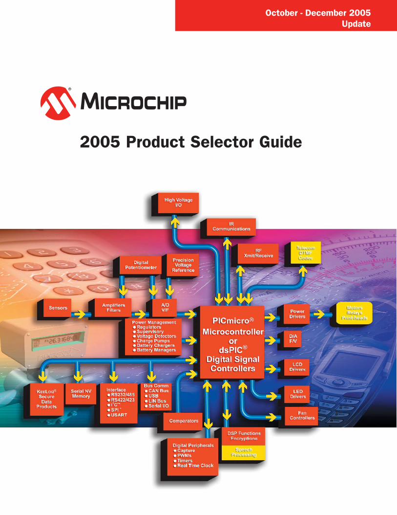
Product Profi le8-bit PICmicro® Microcontrollers
Microchip’s PICmicro® family of microcontrollers combine high performance, low cost and small package size to offer the best price/
performance ratio in the industry. Based on a powerful RISC core, these 8-bit PIC® microcontrollers fall into three product architecture
categories, providing a variety of options for any application requirement:
• Baseline 8-bit architecture: 12-bit instruction set, 6-44 pin count, 384-3.5K bytes program memory, up to 5 MIPS
• Mid-Range 8-bit architecture: 14-bit instruction set, 8-68 pin count, 896-14K bytes program memory, up to 5 MIPS
• High Performance (PIC18) 8-bit architecture: 16-bit instruction set, 18-100 pin count, 8K-128K bytes program memory,
up to 16 MIPS
The common architecture provides users with an easy migration path from 6 to 100 pins among all families with little or no code
change required. Advanced features available are:
• Sophisticated timing peripherals
• Embedded analog peripherals including A/D and D/A converters, comparators, PBOR, PLVD, DAC, VREF, Op Amps and PSMC
• Communications peripherals (I2C™/SPI™/USB/CAN and USARTs)
• Low-power, single-chip RF solutions targeting RF connectivity for high-volume embedded control applications
• Battery management solutions
• Flexible programming options including In-Circuit Serial Programming™ (ICSP™) technology, self-programming (Enhanced
Flash), One-Time-Programmable (OTP), QTP, SQTP and ROM
16-bit PICmicro® Microcontrollers
The PIC24 microcontrollers build upon the high performance, wide selection of peripherals, Flash memory sizes and packaging choices
found in the 8-bit PIC18 family. The PIC24 architecture, paired with the optimized MPLAB C30 C Compiler, provides the high throughput
and C code density needed to achieve system performance goals and product launch schedules.
• Leadership 16-bit microcontroller performance and C code effi ciency
• Extension of the 8-bit PIC18 microcontroller performance, memory and peripherals
• Easy migration path to dsPIC® digital signal controllers with over 40 MIPS and DSP capability, MPLAB® compatibility
16-bit dsPIC® Digital Signal Controllers
Microchip’s 16-bit High Performance Digital Signal Controllers (DSC) combine the best features of microcontrollers with the best
features of DSPs in a single core. These dsPIC DSC devices reach speeds of up to 30 MIPS.
• C compiler effi ciency programming, Flash, data EEPROM, and powerful peripherals
• Extensive software libraries for effortless design
• Familiar microcontroller architecture and design environment
Stand-Alone Analog & Interface Products
Microchip offers a broad portfolio of analog and related products:
• Linear and Mixed-Signal. ADCs/DACs, digital potentiometers, op amps and comparators.
• Power Management. LDO and switching regulators, charge pumps, voltage references, CPU/system supervisors and volt age
detectors, battery chargers and power MOSFET drivers.
• Thermal Management. Temperature sensors (logic output, voltage output, and serial output), brushless DC fan controllers, and
fan fault detectors.
• Interface. Peripheral products supporting industry-standard networking protocols like CAN, LIN and infrared (including IrDA®
Standard infrared), as well as products that provide embedded system input/output expansion capability.
Secure Data Products
Microchip’s KEELOQ® code hopping algorithm combines high security, a small package outline and a very low cost to make this an
ideal solution for unidirectional RKE systems. The KEELOQ code hopping technology creates a high degree of security using a long
code word length together with encryption and synchronization techniques.
Memory ProductsMicrochip offers one of the broadest selections of serial EEPROMs in densities from 128 bits to 512 Kbits, with operating voltages
down to 1.8V, in all popular bus protocols (I2C™, Microwire and SPI™ compatible). They are available in all standard temperature
ranges from -40°C to +125°C and packaged in the world’s smallest standard packaging; up to 16 Kbits in 5-lead SOT-23 and up to
256 Kbits in 8-lead MSOP.
Development Systems
Microchip offers a full range of microcontroller development systems, including the MPLAB® ICE 2000 and ICE 9000 in-circuit
emulators; MPLAB Integrated Development Environment; MPLAB C18 and C30 Compiler; the MPLAB ICD In-Circuit Debugger,
MPLAB PM3 full-featured device programmer; PICSTART® low-cost development system; the PICkit™ 1 Flash Starter Kit, SEEVAL®
Serial EEPROM Evaluation Kit and various demonstration boards. Microchip has shipped more than 300,000+ development systems
worldwide.
PAGE i
TABLE OF CONTENTS
CURRENT dsPIC® DIGITAL SIGNAL CONTROLLER FAMILY PRODUCTS. . . . . . . . 5dsPIC30F Motor Control and Power Conversion Family . . . . . . . . . . . . . . . . . . . . . . . . . . . . . . . . . . . .5dsPIC30F General Purpose Family . . . . . . . . . . . . . . . . . . . . . . . . . . . . . . . . . . . . . . . . . . . . . . . . . . . .5dsPIC30F Sensor Family . . . . . . . . . . . . . . . . . . . . . . . . . . . . . . . . . . . . . . . . . . . . . . . . . . . . . . . . . . . .6
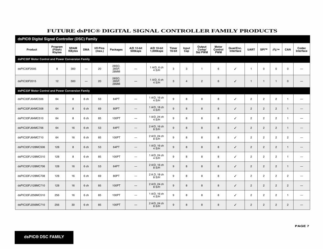
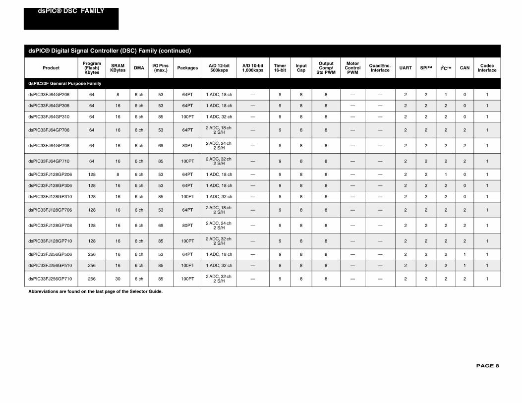
FUTURE dsPIC® DIGITAL SIGNAL CONTROLLER FAMILY PRODUCTS . . . . . . . . . 7dsPIC30F Motor Control and Power Conversion Family . . . . . . . . . . . . . . . . . . . . . . . . . . . . . . . . . . . .7dsPIC33F Motor Control and Power Conversion Family . . . . . . . . . . . . . . . . . . . . . . . . . . . . . . . . . . . .7dsPIC33F General Purpose Family . . . . . . . . . . . . . . . . . . . . . . . . . . . . . . . . . . . . . . . . . . . . . . . . . . . .8
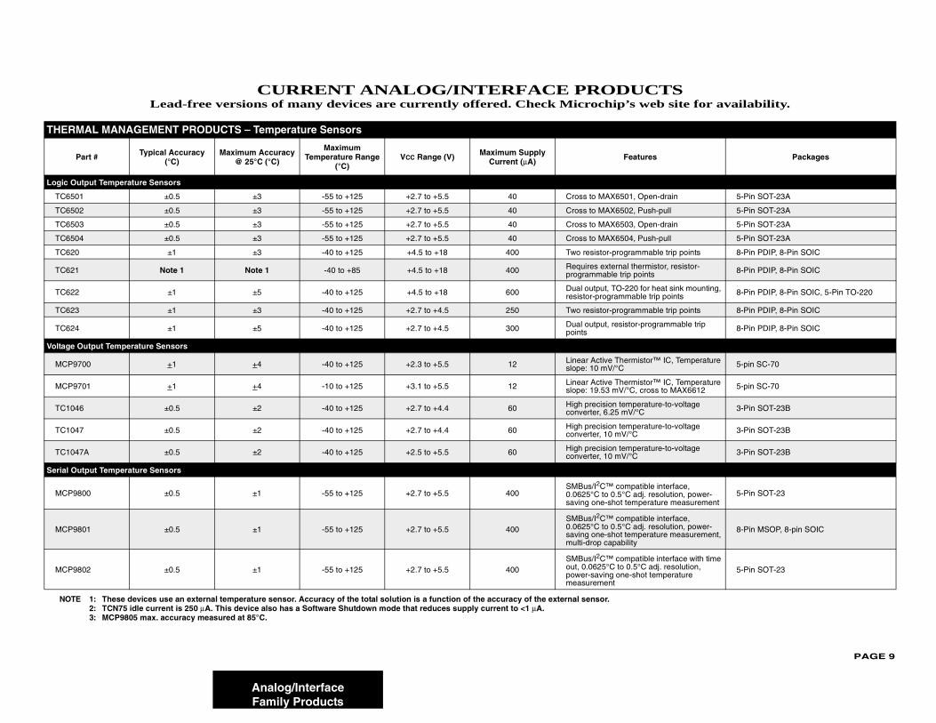
CURRENT ANALOG/INTERFACE PRODUCTS . . . . . . . . . . . . . . . . . . . . . . . . . . . . . . 9THERMAL MANAGEMENT PRODUCTS – Temperature Sensors . . . . . . . . . . . . . . . . . . . . . . . . . . . .9
Logic Output Temperature Sensors . . . . . . . . . . . . . . . . . . . . . . . . . . . . . . . . . . . . . . . . . . . . . . . .9Voltage Output Temperature Sensors. . . . . . . . . . . . . . . . . . . . . . . . . . . . . . . . . . . . . . . . . . . . . . .9Serial Output Temperature Sensors . . . . . . . . . . . . . . . . . . . . . . . . . . . . . . . . . . . . . . . . . . . . . . . .9
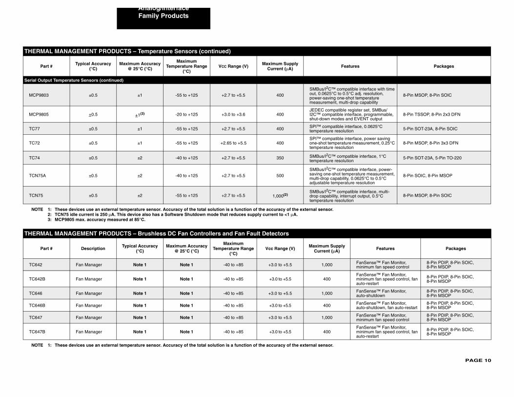
THERMAL MANAGEMENT PRODUCTS – Brushless DC Fan Controllers and Fan Fault Detectors . . . . . . . . . . . . . . . . . . . . . . . . . . . . . . . . . . . . . . . . . . . . . . . . . . . . . . . . . . . . . . .10POWER MANAGEMENT – Voltage References . . . . . . . . . . . . . . . . . . . . . . . . . . . . . . . . . . . . . . . . .11POWER MANAGEMENT – Linear Regulators . . . . . . . . . . . . . . . . . . . . . . . . . . . . . . . . . . . . . . . . . .12
50 mA to 250 mA Low Dropout Linear Regulators . . . . . . . . . . . . . . . . . . . . . . . . . . . . . . . . . . . .12300 mA Low Dropout Linear Regulators . . . . . . . . . . . . . . . . . . . . . . . . . . . . . . . . . . . . . . . . . . . .13500 mA to 800 mA Low Dropout Linear Regulators . . . . . . . . . . . . . . . . . . . . . . . . . . . . . . . . . . .131A and Above Low Dropout Linear Regulators . . . . . . . . . . . . . . . . . . . . . . . . . . . . . . . . . . . . . . .13Application Specific Low Dropout Linear Regulators. . . . . . . . . . . . . . . . . . . . . . . . . . . . . . . . . . .13Power Management Combination Products . . . . . . . . . . . . . . . . . . . . . . . . . . . . . . . . . . . . . . . . .13
POWER MANAGEMENT – Switching Regulators. . . . . . . . . . . . . . . . . . . . . . . . . . . . . . . . . . . . . . . .14POWER MANAGEMENT – PWM Controllers . . . . . . . . . . . . . . . . . . . . . . . . . . . . . . . . . . . . . . . . . . .15POWER MANAGEMENT – Charge Pump DC-to-DC Converters . . . . . . . . . . . . . . . . . . . . . . . . . . . .15
Inverting or Doubling Charge Pumps . . . . . . . . . . . . . . . . . . . . . . . . . . . . . . . . . . . . . . . . . . . . . .15Multi-Function Charge Pumps . . . . . . . . . . . . . . . . . . . . . . . . . . . . . . . . . . . . . . . . . . . . . . . . . . . .16Inverting and Doubling Charge Pumps . . . . . . . . . . . . . . . . . . . . . . . . . . . . . . . . . . . . . . . . . . . . .16Regulated Charge Pumps . . . . . . . . . . . . . . . . . . . . . . . . . . . . . . . . . . . . . . . . . . . . . . . . . . . . . . .16
POWER MANAGEMENT – CPU/System Supervisors . . . . . . . . . . . . . . . . . . . . . . . . . . . . . . . . . . . .16POWER MANAGEMENT – Voltage Detectors . . . . . . . . . . . . . . . . . . . . . . . . . . . . . . . . . . . . . . . . . .17POWER MANAGEMENT – Power MOSFET Drivers . . . . . . . . . . . . . . . . . . . . . . . . . . . . . . . . . . . . .17
Low-Side Drivers, 0.5A to 1.2A Peak Output Current . . . . . . . . . . . . . . . . . . . . . . . . . . . . . . . . . .17Low-Side Drivers, 1.5A Peak Output Current . . . . . . . . . . . . . . . . . . . . . . . . . . . . . . . . . . . . . . . .18Low-Side Drivers, 2.0A to 9.0A Peak Output Current . . . . . . . . . . . . . . . . . . . . . . . . . . . . . . . . . .18High-Side/Low-Side Drivers . . . . . . . . . . . . . . . . . . . . . . . . . . . . . . . . . . . . . . . . . . . . . . . . . . . . .19
POWER MANAGEMENT – Battery Chargers . . . . . . . . . . . . . . . . . . . . . . . . . . . . . . . . . . . . . . . . . . .19POWER MANAGEMENT – Hot Swap Controllers. . . . . . . . . . . . . . . . . . . . . . . . . . . . . . . . . . . . . . . .19
PAGE ii
LINEAR – Op Amps . . . . . . . . . . . . . . . . . . . . . . . . . . . . . . . . . . . . . . . . . . . . . . . . . . . . . . . . . . . . . . .20LINEAR – High Precision Operational Amplifiers. . . . . . . . . . . . . . . . . . . . . . . . . . . . . . . . . . . . . . . . .22
Chopper Stabilized . . . . . . . . . . . . . . . . . . . . . . . . . . . . . . . . . . . . . . . . . . . . . . . . . . . . . . . . . . . .22Auto-Zero. . . . . . . . . . . . . . . . . . . . . . . . . . . . . . . . . . . . . . . . . . . . . . . . . . . . . . . . . . . . . . . . . . . .22
LINEAR – Programmable Gain Amplifiers (PGA) . . . . . . . . . . . . . . . . . . . . . . . . . . . . . . . . . . . . . . . .22LINEAR – Integrated Devices . . . . . . . . . . . . . . . . . . . . . . . . . . . . . . . . . . . . . . . . . . . . . . . . . . . . . . .22LINEAR – Comparators . . . . . . . . . . . . . . . . . . . . . . . . . . . . . . . . . . . . . . . . . . . . . . . . . . . . . . . . . . . .23MIXED SIGNAL – Successive Approximation Register (SAR) A/D Converters. . . . . . . . . . . . . . . . . .23MIXED SIGNAL – Delta-Sigma A/D Converters . . . . . . . . . . . . . . . . . . . . . . . . . . . . . . . . . . . . . . . . .24MIXED SIGNAL – Energy Measurement ICs. . . . . . . . . . . . . . . . . . . . . . . . . . . . . . . . . . . . . . . . . . . .24MIXED SIGNAL – Dual Slope A/D Converters . . . . . . . . . . . . . . . . . . . . . . . . . . . . . . . . . . . . . . . . . .24MIXED SIGNAL – Binary and BCD A/D Converters . . . . . . . . . . . . . . . . . . . . . . . . . . . . . . . . . . . . . .25MIXED SIGNAL – Display A/D Converters . . . . . . . . . . . . . . . . . . . . . . . . . . . . . . . . . . . . . . . . . . . . .25MIXED SIGNAL – Digital Potentiometers . . . . . . . . . . . . . . . . . . . . . . . . . . . . . . . . . . . . . . . . . . . . . .25MIXED SIGNAL – Frequency-to-Voltage/Voltage-to-Frequency Converters. . . . . . . . . . . . . . . . . . . .26MIXED SIGNAL – D/A Converters . . . . . . . . . . . . . . . . . . . . . . . . . . . . . . . . . . . . . . . . . . . . . . . . . . . .26INTERFACE – Controller Area Network (CAN) Products . . . . . . . . . . . . . . . . . . . . . . . . . . . . . . . . . .27INTERFACE – Infrared Products . . . . . . . . . . . . . . . . . . . . . . . . . . . . . . . . . . . . . . . . . . . . . . . . . . . . .27INTERFACE – Ethernet Products . . . . . . . . . . . . . . . . . . . . . . . . . . . . . . . . . . . . . . . . . . . . . . . . . . . .27INTERFACE – LIN Transceiver Products . . . . . . . . . . . . . . . . . . . . . . . . . . . . . . . . . . . . . . . . . . . . . .28INTERFACE – Serial Peripherals . . . . . . . . . . . . . . . . . . . . . . . . . . . . . . . . . . . . . . . . . . . . . . . . . . . .28
FUTURE ANALOG/INTERFACE PRODUCTS . . . . . . . . . . . . . . . . . . . . . . . . . . . . . . 29Power Management – Low-Side Power MOSFET Drivers . . . . . . . . . . . . . . . . . . . . . . . . . . . . . . . . .29Power Management – Battery Chargers . . . . . . . . . . . . . . . . . . . . . . . . . . . . . . . . . . . . . . . . . . . . . . .29Power Management – Charge Pump DC/DC Converters . . . . . . . . . . . . . . . . . . . . . . . . . . . . . . . . . .29Power Management – Linear Regulators. . . . . . . . . . . . . . . . . . . . . . . . . . . . . . . . . . . . . . . . . . . . . . .29Power Management – Switching Regulators . . . . . . . . . . . . . . . . . . . . . . . . . . . . . . . . . . . . . . . . . . . .29Power Management – CPU/System Supervisors . . . . . . . . . . . . . . . . . . . . . . . . . . . . . . . . . . . . . . . .29Linear – Linear Gain Blocks. . . . . . . . . . . . . . . . . . . . . . . . . . . . . . . . . . . . . . . . . . . . . . . . . . . . . . . . .30Mixed Signal – Successive Approximation Register (SAR) A/D Converters . . . . . . . . . . . . . . . . . . . .30Interface – Passive Access Products. . . . . . . . . . . . . . . . . . . . . . . . . . . . . . . . . . . . . . . . . . . . . . . . . .30
CURRENT PICmicro® MICROCONTROLLER FAMILY PRODUCTS . . . . . . . . . . . . . 31Baseline 8-Bit PICmicro® Microcontroller Family (12-bit Instruction Set) . . . . . . . . . . . . . . . . . . . . . .31
PIC10FXXX . . . . . . . . . . . . . . . . . . . . . . . . . . . . . . . . . . . . . . . . . . . . . . . . . . . . . . . . . . . . . . . . . .31PIC12FXXX . . . . . . . . . . . . . . . . . . . . . . . . . . . . . . . . . . . . . . . . . . . . . . . . . . . . . . . . . . . . . . . . . .31PIC16F5XX . . . . . . . . . . . . . . . . . . . . . . . . . . . . . . . . . . . . . . . . . . . . . . . . . . . . . . . . . . . . . . . . . .31PIC16C5X . . . . . . . . . . . . . . . . . . . . . . . . . . . . . . . . . . . . . . . . . . . . . . . . . . . . . . . . . . . . . . . . . . .31
Mid-Range 8-Bit PICmicro® Microcontroller Family (14-bit Instruction Set) . . . . . . . . . . . . . . . . . . . .32PIC12FXXX . . . . . . . . . . . . . . . . . . . . . . . . . . . . . . . . . . . . . . . . . . . . . . . . . . . . . . . . . . . . . . . . . .32PIC16FXXX . . . . . . . . . . . . . . . . . . . . . . . . . . . . . . . . . . . . . . . . . . . . . . . . . . . . . . . . . . . . . . . . . .32PIC16CXXX. . . . . . . . . . . . . . . . . . . . . . . . . . . . . . . . . . . . . . . . . . . . . . . . . . . . . . . . . . . . . . . . . .34
PAGE iii
High-Performance 8-Bit PICmicro® Microcontroller Family (16-bit Instruction Set) . . . . . . . . . . . . . .35PIC18 Flash MCUs . . . . . . . . . . . . . . . . . . . . . . . . . . . . . . . . . . . . . . . . . . . . . . . . . . . . . . . . . . . .35PIC18FXXJXX . . . . . . . . . . . . . . . . . . . . . . . . . . . . . . . . . . . . . . . . . . . . . . . . . . . . . . . . . . . . . . . .39
FUTURE PICmicro® MICROCONTROLLER FAMILY PRODUCTS. . . . . . . . . . . . . . . 40Mid-Range 8-Bit PICmicro® Microcontroller Family (14-bit Instruction Set) . . . . . . . . . . . . . . . . . . . .40
PIC12FXXX . . . . . . . . . . . . . . . . . . . . . . . . . . . . . . . . . . . . . . . . . . . . . . . . . . . . . . . . . . . . . . . . . .40PIC16FXXX . . . . . . . . . . . . . . . . . . . . . . . . . . . . . . . . . . . . . . . . . . . . . . . . . . . . . . . . . . . . . . . . . .40PIC16CRXX. . . . . . . . . . . . . . . . . . . . . . . . . . . . . . . . . . . . . . . . . . . . . . . . . . . . . . . . . . . . . . . . . .40
High-Performance 8-Bit PICmicro® Microcontroller Family (16-bit Instruction Set) . . . . . . . . . . . . . .40PIC18FXXX . . . . . . . . . . . . . . . . . . . . . . . . . . . . . . . . . . . . . . . . . . . . . . . . . . . . . . . . . . . . . . . . . .40PIC18FXXJXX . . . . . . . . . . . . . . . . . . . . . . . . . . . . . . . . . . . . . . . . . . . . . . . . . . . . . . . . . . . . . . . .41PIC18FXXKXX . . . . . . . . . . . . . . . . . . . . . . . . . . . . . . . . . . . . . . . . . . . . . . . . . . . . . . . . . . . . . . .42
PIC24 16-Bit Microcontroller (MCU) Family . . . . . . . . . . . . . . . . . . . . . . . . . . . . . . . . . . . . . . . . . . . . .43PIC24FJ128GA Family 16-bit Flash MCUs . . . . . . . . . . . . . . . . . . . . . . . . . . . . . . . . . . . . . . . . . .43PIC24HJ256GP Family 16-bit Flash MCUs. . . . . . . . . . . . . . . . . . . . . . . . . . . . . . . . . . . . . . . . . .43
MATURE – PICmicro® MICROCONTROLLER FAMILY PRODUCTS . . . . . . . . . . . . . 45
FOCUSED SOLUTIONS. . . . . . . . . . . . . . . . . . . . . . . . . . . . . . . . . . . . . . . . . . . . . . . . 47CAN Solutions . . . . . . . . . . . . . . . . . . . . . . . . . . . . . . . . . . . . . . . . . . . . . . . . . . . . . . . . . . . . . . . . . . .47CAN Peripherals/Transceivers. . . . . . . . . . . . . . . . . . . . . . . . . . . . . . . . . . . . . . . . . . . . . . . . . . . . . . .48Ethernet Solutions – Integrated . . . . . . . . . . . . . . . . . . . . . . . . . . . . . . . . . . . . . . . . . . . . . . . . . . . . . .49Ethernet Solutions – Stand-Alone . . . . . . . . . . . . . . . . . . . . . . . . . . . . . . . . . . . . . . . . . . . . . . . . . . . .49USB Solutions . . . . . . . . . . . . . . . . . . . . . . . . . . . . . . . . . . . . . . . . . . . . . . . . . . . . . . . . . . . . . . . . . . .49USB Battery Chargers . . . . . . . . . . . . . . . . . . . . . . . . . . . . . . . . . . . . . . . . . . . . . . . . . . . . . . . . . . . . .50Switching Battery Chargers . . . . . . . . . . . . . . . . . . . . . . . . . . . . . . . . . . . . . . . . . . . . . . . . . . . . . . . . .51Battery Fuel Gauge ICs . . . . . . . . . . . . . . . . . . . . . . . . . . . . . . . . . . . . . . . . . . . . . . . . . . . . . . . . . . . .51Radio Frequency Solutions . . . . . . . . . . . . . . . . . . . . . . . . . . . . . . . . . . . . . . . . . . . . . . . . . . . . . . . . .51
rfPIC® Microcontrollers with UHF RF Transmitter, ICSP™. . . . . . . . . . . . . . . . . . . . . . . . . . . . . .51rfHCS KEELOQ® Encoders with UHF RF Transmitter . . . . . . . . . . . . . . . . . . . . . . . . . . . . . . . . . .51UHF RF Receiver . . . . . . . . . . . . . . . . . . . . . . . . . . . . . . . . . . . . . . . . . . . . . . . . . . . . . . . . . . . . .52microID® RFID Tagging Devices . . . . . . . . . . . . . . . . . . . . . . . . . . . . . . . . . . . . . . . . . . . . . . . . .52
LCD Solutions . . . . . . . . . . . . . . . . . . . . . . . . . . . . . . . . . . . . . . . . . . . . . . . . . . . . . . . . . . . . . . . . . . .52Display Solutions . . . . . . . . . . . . . . . . . . . . . . . . . . . . . . . . . . . . . . . . . . . . . . . . . . . . . . . . . . . . . . . . .53Motor Control Solutions. . . . . . . . . . . . . . . . . . . . . . . . . . . . . . . . . . . . . . . . . . . . . . . . . . . . . . . . . . . .54Motor Control Solutions – MOSFET Drivers . . . . . . . . . . . . . . . . . . . . . . . . . . . . . . . . . . . . . . . . . . . .55Motor Control Solutions – LINEAR – Comparators . . . . . . . . . . . . . . . . . . . . . . . . . . . . . . . . . . . . . . .55Motor Control Solutions – LINEAR – Op Amps . . . . . . . . . . . . . . . . . . . . . . . . . . . . . . . . . . . . . . . . . .56Motor Control Solutions – LINEAR – High Precision Operational Amplifiers . . . . . . . . . . . . . . . . . . . .58High-Speed Sensor Solutions . . . . . . . . . . . . . . . . . . . . . . . . . . . . . . . . . . . . . . . . . . . . . . . . . . . . . . .59Power-Managed Solutions Featuring nanoWatt Technology. . . . . . . . . . . . . . . . . . . . . . . . . . . . . . . .60
PAGE iv
CURRENT SECURE DATA PRODUCTS. . . . . . . . . . . . . . . . . . . . . . . . . . . . . . . . . . . 61KEELOQ® Encoder Devices . . . . . . . . . . . . . . . . . . . . . . . . . . . . . . . . . . . . . . . . . . . . . . . . . . . . . . . . .61KEELOQ® Decoder Devices . . . . . . . . . . . . . . . . . . . . . . . . . . . . . . . . . . . . . . . . . . . . . . . . . . . . . . . . .61KEELOQ® Programmable Encoder/Decoder Flash Devices (x14), ICSP™ . . . . . . . . . . . . . . . . . . . . .61
CURRENT SERIAL ELECTRICALLY ERASABLE PROMS (EEPROM) . . . . . . . . . . 62Microwire Compatible Serial EEPROM Family . . . . . . . . . . . . . . . . . . . . . . . . . . . . . . . . . . . . . . . . . .622-Wire I2C™ Compatible Serial EEPROM Family . . . . . . . . . . . . . . . . . . . . . . . . . . . . . . . . . . . . . . . .63SPI™ Compatible Serial EEPROM Family. . . . . . . . . . . . . . . . . . . . . . . . . . . . . . . . . . . . . . . . . . . . . .64ISO Smart Card Family. . . . . . . . . . . . . . . . . . . . . . . . . . . . . . . . . . . . . . . . . . . . . . . . . . . . . . . . . . . . .64Identification Products . . . . . . . . . . . . . . . . . . . . . . . . . . . . . . . . . . . . . . . . . . . . . . . . . . . . . . . . . . . . .65
FUTURE SERIAL ELECTRICALLY ERASABLE PROMS (EEPROM) . . . . . . . . . . . . 66SPI™ Compatible Serial EEPROM Family . . . . . . . . . . . . . . . . . . . . . . . . . . . . . . . . . . . . . . . . . . . . .66I2C™ Compatible Serial EEPROM Family. . . . . . . . . . . . . . . . . . . . . . . . . . . . . . . . . . . . . . . . . . . . . .66
DEVELOPMENT SYSTEMS. . . . . . . . . . . . . . . . . . . . . . . . . . . . . . . . . . . . . . . . . . . . . 67MPLAB® ICE 2000 and MPLAB® ICE 4000 Emulator Systems . . . . . . . . . . . . . . . . . . . . . . . . . . . . .67How Do I Order MPLAB® ICE? . . . . . . . . . . . . . . . . . . . . . . . . . . . . . . . . . . . . . . . . . . . . . . . . . . . . . .67A Complete MPLAB® ICE System. . . . . . . . . . . . . . . . . . . . . . . . . . . . . . . . . . . . . . . . . . . . . . . . . . . .67MPLAB® PM3 Programmers . . . . . . . . . . . . . . . . . . . . . . . . . . . . . . . . . . . . . . . . . . . . . . . . . . . . . . . .67In-Circuit Debuggers: MPLAB® ICD 2 . . . . . . . . . . . . . . . . . . . . . . . . . . . . . . . . . . . . . . . . . . . . . . . . .67MPLAB® ICE 2000 and MPLAB® ICE 4000 Emulator Systems, PRO MATE® II Programmer Socket Modules, MPLAB® In-Circuit Debugger, Software Tools, Programmers & Demonstration Boards. . .68
Analog Interface Development Tools . . . . . . . . . . . . . . . . . . . . . . . . . . . . . . . . . . . . . . . . . . . . . .68PICmicro® Microcontroller Development Tools. . . . . . . . . . . . . . . . . . . . . . . . . . . . . . . . . . . . . . .68rfPIC® Microcontroller Development Tools . . . . . . . . . . . . . . . . . . . . . . . . . . . . . . . . . . . . . . . . . .98dsPIC® DSC Development Tools . . . . . . . . . . . . . . . . . . . . . . . . . . . . . . . . . . . . . . . . . . . . . . . . .99
Demonstration Boards and Evaluation Kits . . . . . . . . . . . . . . . . . . . . . . . . . . . . . . . . . . . . . . . . . . . .103PICmicro® Demonstration Kits . . . . . . . . . . . . . . . . . . . . . . . . . . . . . . . . . . . . . . . . . . . . . . . . . .103Connectivity Demonstration Kits . . . . . . . . . . . . . . . . . . . . . . . . . . . . . . . . . . . . . . . . . . . . . . . . .103Mixed Signal Control Demonstration Kits . . . . . . . . . . . . . . . . . . . . . . . . . . . . . . . . . . . . . . . . . .104dsPIC® Digital Signal Controller Demonstration Kits . . . . . . . . . . . . . . . . . . . . . . . . . . . . . . . . .104dsPIC® 16-bit DSC Software Tools. . . . . . . . . . . . . . . . . . . . . . . . . . . . . . . . . . . . . . . . . . . . . . .104
PowerSmart® Systems . . . . . . . . . . . . . . . . . . . . . . . . . . . . . . . . . . . . . . . . . . . . . . . . . . . . . . . . . . .105Memory Evaluation/Developer’s Kits . . . . . . . . . . . . . . . . . . . . . . . . . . . . . . . . . . . . . . . . . . . . . . . . .105KeeLoq® Evaluation Kits . . . . . . . . . . . . . . . . . . . . . . . . . . . . . . . . . . . . . . . . . . . . . . . . . . . . . . . . . .106RFID Evaluation/Developer’s Kits . . . . . . . . . . . . . . . . . . . . . . . . . . . . . . . . . . . . . . . . . . . . . . . . . . .106Analog/Interface Demo/Eval/Developer’s Kits . . . . . . . . . . . . . . . . . . . . . . . . . . . . . . . . . . . . . . . . . .106
PIN AND CODE COMPATIBILITY CHART . . . . . . . . . . . . . . . . . . . . . . . . . . . . . . . . 108
PART NUMBER SUFFIX DESIGNATIONS . . . . . . . . . . . . . . . . . . . . . . . . . . . . . . . . 116
ABBREVIATIONS . . . . . . . . . . . . . . . . . . . . . . . . . . . . . . . . . . . . . . . . . . . . . . . . . . . 119
PAGE 5
d
ILY PRODUCTS
dsPI
Protor
ontrol PWM
Quad Enc. UART SPI™ I2C™ CAN Codec
Interface
dsPIC
dsPIC 6 ✓ 1 1 1 — —
dsPIC 6 ✓ 1 1 1 — —
dsPIC 6 ✓ 1 1 1 1 —
dsPIC 6 ✓ 2 1 1 — —
dsPIC 6 ✓ 2 1 1 1 —
dsPIC 8 ✓ 1 2 1 1 —
dsPIC 8 ✓ 2 2 1 2 —
dsPIC 8 ✓ 1 2 1 1 —
dsPIC 8 ✓ 2 2 1 2 —
dsPIC 8 ✓ 2 2 1 2 —
dsPIC
dsPIC — — 2 1 1 — —
dsPIC — — 2 1 1 1 AC97, I2S
dsPIC — — 2 2 1 2 AC97, I2S
dsPIC — — 2 2 1 2 —
dsPIC — — 2 2 1 2 —
dsPIC — — 2 2 1 2 AC97, I2S
dsPIC — — 2 2 1 2 AC97, I2S
dsPIC — — 2 2 1 2 AC97, I2S
dsPIC — — 2 2 1 2 —
dsPIC — — 2 2 1 2 —
Abbre
NEW
NEW
NEW
NEW
NEW
NEW
NEW
sPIC® DSC FAMILY
CURRENT dsPIC® DIGITAL SIGNAL CONTROLLER FAM
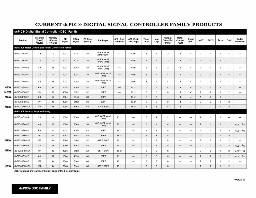
C® Digital Signal Controller (DSC) Family
oductProgram (Flash)KBytes
Memory (Flash)
KWords
EEBytes
SRAM Bytes
I/O Pins (max.) Packages A/D 12-bit
200 kspsA/D 10-bit 1000 ksps
Timer 16-bit
Input Cap
Output Comp/Std
PWM
MC
30F Motor Control and Power Conversion Family
30F2010 12 4 1024 512 20 28SO, 28SP, 28MM (6x6) — 6 ch 3 4 2
30F3010 24 8 1024 1024 20 28SO, 28SP, 44ML (8x8) — 6 ch 5 4 2
30F4012 48 16 1024 2048 20 28SO, 28SP, 44ML (8x8) — 6 ch 5 4 2
30F3011 24 8 1024 1024 30 40P, 44PT, 44ML (8x8) — 9 ch 5 4 4
30F4011 48 16 1024 2048 30 40P, 44PT, 44ML (8x8) — 9 ch 5 4 4
30F5015 66 22 1024 2048 52 64PT — 16 ch 5 4 4
30F6015 144 48 4096 8192 52 64PT — 16 ch 5 8 8
30F5016 66 22 1024 2048 68 80PT — 16 ch 5 4 4
30F6010 144 48 4096 8192 68 80PF — 16 ch 5 8 8
30F6010A 144 48 4096 8192 68 80PF, 80PT — 16 ch 5 8 8
30F General Purpose Family
30F3014 24 8 1024 2048 30 40P, 44PT, 44ML (8x8) 13 ch — 3 2 2
30F4013 48 16 1024 2048 30 40P, 44PT, 44ML (8x8) 13 ch — 5 4 4
30F5011 66 22 1024 4096 52 64PT 16 ch — 5 8 8
30F6011 132 44 2048 6144 52 64PF 16 ch — 5 8 8
30F6011A 132 44 2048 6144 52 64PF, 64PT 16 ch — 5 8 8
30F6012 144 48 4096 8192 52 64PF 16 ch — 5 8 8
30F6012A 144 48 4096 8192 52 64PF, 64PT 16 ch — 5 8 8
30F5013 66 22 1024 4096 68 80PT 16 ch — 5 8 8
30F6013 132 44 2048 6144 68 80PF 16 ch — 5 8 8
30F6013A 132 44 2048 6144 68 80PF, 80PT 16 ch — 5 8 8
viations are found on the last page of the Selector Guide.
PAGE 6
dsPIC® DSC FAMILY
dsPIC3
dsPIC3 — — 2 2 1 2 AC97, I2S
dsPIC3 — — 2 2 1 2 AC97, I2S
dsPIC3
dsPIC3 — — 1 1 1 — —
dsPIC3 — — 1 1 1 — —
dsPIC3 — — 1 1 1 — —
dsPIC3 — — 2 1 1 — —
dsPIC
Protor
ontrol WM
Quad Enc. UART SPI™ I2C™ CAN Codec
Interface
Abbrev
NEW
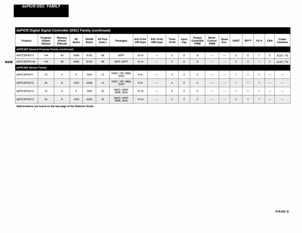
0F General Purpose Family (continued)
0F6014 144 48 4096 8192 68 80PF 16 ch — 5 8 8
0F6014A 144 48 4096 8192 68 80PF, 80PT 16 ch — 5 8 8
0F Sensor Family
0F2011 12 4 0 1024 12 18SO, 18P, 28ML (6x6) 8 ch — 3 2 2
0F3012 24 8 1024 2048 12 18SO, 18P, 28ML (6x6) 8 ch — 3 2 2
0F2012 12 4 0 1024 20 28SO, 28SP, 28ML (6x6) 10 ch — 3 2 2
0F3013 24 8 1024 2048 20 28SO, 28SP, 28ML (6x6) 10 ch — 3 2 2
® Digital Signal Controller (DSC) Family (continued)
oductProgram (Flash)KBytes
Memory (Flash)KWords
EEBytes
SRAM Bytes
I/O Pins (max.) Packages A/D 12-bit
200 kspsA/D 10-bit 1000 ksps
Timer 16-bit
Input Cap
Output Comp/Std
PWM
MC
P
iations are found on the last page of the Selector Guide.
PAGE 7
d
ILY PRODUCTS
dsPIC
Quad Enc. Interface UART SPI™ I2C™ CAN Codec
Interface
dsPIC3
dsPIC3 ✓ 1 0 0 0 —
dsPIC3 ✓ 1 1 1 0 —
dsPIC3
dsPIC3 ✓ 2 2 2 1 —
dsPIC3 ✓ 2 2 2 1 —
dsPIC3 ✓ 2 2 2 1 —
dsPIC3 ✓ 2 2 2 1 —
dsPIC3 ✓ 2 2 2 2 —
dsPIC3 ✓ 2 2 2 1 —
dsPIC3 ✓ 2 2 2 1 —
dsPIC3 ✓ 2 2 2 1 —
dsPIC3 ✓ 2 2 2 2 —
dsPIC3 ✓ 2 2 2 2 —
dsPIC3 ✓ 2 2 2 1 —
dsPIC3 ✓ 2 2 2 2 —
sPIC® DSC FAMILY
FUTURE dsPIC® DIGITAL SIGNAL CONTROLLER FAM
® Digital Signal Controller (DSC) Family
ProductProgram (Flash) Kbytes
SRAM KBytes DMA I/O Pins
(max.) Packages A/D 12-bit 500ksps
A/D 10-bit 1,000ksps
Timer 16-bit
Input Cap
Output Comp/
Std PWM
Motor Control
PWM
0F Motor Control and Power Conversion Family
0F2005 8 300 — 2028SO, 28SP, 28MM
— 1 A/D, 6 ch 4 S/H 3 3 1 6
0F2015 12 500 — 2028SO, 28SP, 28MM
— 1 A/D, 6 ch 4 S/H 3 4 2 6
3F Motor Control and Power Conversion Family
3FJ64MC506 64 8 6 ch 53 64PT — 1 A/D, 16 ch 4 S/H 9 8 8 8
3FJ64MC508 64 8 6 ch 69 80PT — 1 A/D, 18 ch 4 S/H 9 8 8 8
3FJ64MC510 64 8 6 ch 85 100PT — 1 A/D, 24 ch 4 S/H 9 8 8 8
3FJ64MC706 64 16 6 ch 53 64PT — 2 A/D, 16 ch 8 S/H 9 8 8 8
3FJ64MC710 64 16 6 ch 85 100PT — 2 A/D, 24 ch 8 S/H 9 8 8 8
3FJ128MC506 128 8 6 ch 53 64PT — 1 A/D, 16 ch 4 S/H 9 8 8 8
3FJ128MC510 128 8 6 ch 85 100PT — 1 A/D, 24 ch 4 S/H 9 8 8 8
3FJ128MC706 128 16 6 ch 53 64PT — 2 A/D, 16 ch 8 S/H 9 8 8 8
3FJ128MC708 128 16 6 ch 69 80PT — 2 A.D, 18 ch 8 S/H 9 8 8 8
3FJ128MC710 128 16 6 ch 85 100PT — 2 A/D, 24 ch 8 S/H 9 8 8 8
3FJ256MC510 256 16 6 ch 85 100PT — 1 A/D, 16 ch 4 S/H 9 8 8 8
3FJ256MC710 256 30 6 ch 85 100PT — 2 A/D, 24 ch 8 S/H 9 8 8 8
PAGE 8
dsPIC® DSC FAMILY
dsPIC
dsPIC — 2 2 1 0 1
dsPIC — 2 2 2 0 1
dsPIC — 2 2 2 0 1
dsPIC — 2 2 2 2 1
dsPIC — 2 2 2 2 1
dsPIC — 2 2 2 2 1
dsPIC — 2 2 1 0 1
dsPIC — 2 2 2 0 1
dsPIC — 2 2 2 0 1
dsPIC — 2 2 2 2 1
dsPIC — 2 2 2 2 1
dsPIC — 2 2 2 2 1
dsPIC — 2 2 2 1 1
dsPIC — 2 2 2 1 1
dsPIC — 2 2 2 2 1
Abbre
dsP
l Quad Enc.
Interface UART SPI™ I2C™ CAN Codec Interface
33F General Purpose Family
33FJ64GP206 64 8 6 ch 53 64PT 1 ADC, 18 ch — 9 8 8 —
33FJ64GP306 64 16 6 ch 53 64PT 1 ADC, 18 ch — 9 8 8 —
33FJ64GP310 64 16 6 ch 85 100PT 1 ADC, 32 ch — 9 8 8 —
33FJ64GP706 64 16 6 ch 53 64PT 2 ADC, 18 ch 2 S/H — 9 8 8 —
33FJ64GP708 64 16 6 ch 69 80PT 2 ADC, 24 ch 2 S/H — 9 8 8 —
33FJ64GP710 64 16 6 ch 85 100PT 2 ADC, 32 ch 2 S/H — 9 8 8 —
33FJ128GP206 128 8 6 ch 53 64PT 1 ADC, 18 ch — 9 8 8 —
33FJ128GP306 128 16 6 ch 53 64PT 1 ADC, 18 ch — 9 8 8 —
33FJ128GP310 128 16 6 ch 85 100PT 1 ADC, 32 ch — 9 8 8 —
33FJ128GP706 128 16 6 ch 53 64PT 2 ADC, 18 ch 2 S/H — 9 8 8 —
33FJ128GP708 128 16 6 ch 69 80PT 2 ADC, 24 ch 2 S/H — 9 8 8 —
33FJ128GP710 128 16 6 ch 85 100PT 2 ADC, 32 ch 2 S/H — 9 8 8 —
33FJ256GP506 256 16 6 ch 53 64PT 1 ADC, 18 ch — 9 8 8 —
33FJ256GP510 256 16 6 ch 85 100PT 1 ADC, 32 ch — 9 8 8 —
33FJ256GP710 256 30 6 ch 85 100PT 2 ADC, 32 ch 2 S/H — 9 8 8 —
viations are found on the last page of the Selector Guide.
IC® Digital Signal Controller (DSC) Family (continued)
ProductProgram (Flash) Kbytes
SRAM KBytes DMA I/O Pins
(max.) Packages A/D 12-bit 500ksps
A/D 10-bit 1,000ksps
Timer 16-bit
Input Cap
Output Comp/
Std PWM
MotorControPWM
PAGE 9
TSeb site for availability.
THER
s Packages
Logic O
TC65 n-drain 5-Pin SOT-23A
TC65 h-pull 5-Pin SOT-23A
TC65 n-drain 5-Pin SOT-23A
TC65 h-pull 5-Pin SOT-23A
TC62 ble trip points 8-Pin PDIP, 8-Pin SOIC
TC62 istor, resistor-s 8-Pin PDIP, 8-Pin SOIC
TC62 heat sink mounting, rip points 8-Pin PDIP, 8-Pin SOIC, 5-Pin TO-220
TC62 ble trip points 8-Pin PDIP, 8-Pin SOIC
TC62 grammable trip 8-Pin PDIP, 8-Pin SOIC
Voltage
MCP9 r™ IC, Temperature 5-pin SC-70
MCP9 r™ IC, Temperature ss to MAX6612 5-pin SC-70
TC10 ure-to-voltage 3-Pin SOT-23B
TC10 ure-to-voltage 3-Pin SOT-23B
TC10 ure-to-voltage 3-Pin SOT-23B
Serial O
MCP9e interface, esolution, power-ature measurement
5-Pin SOT-23
MCP9e interface, esolution, power-ature measurement,
8-Pin MSOP, 8-pin SOIC
MCP9e interface with time dj. resolution,
temperature 5-Pin SOT-23
NOT
Analog/InterfaceFamily Products
CURRENT ANALOG/INTERFACE PRODUCLead-free versions of many devices are currently offered. Check Microchip’s w
MAL MANAGEMENT PRODUCTS – Temperature Sensors
Part # Typical Accuracy (°C)
Maximum Accuracy @ 25°C (°C)
Maximum Temperature Range
(°C)VCC Range (V) Maximum Supply
Current (μA) Feature
utput Temperature Sensors
01 ±0.5 ±3 -55 to +125 +2.7 to +5.5 40 Cross to MAX6501, Ope
02 ±0.5 ±3 -55 to +125 +2.7 to +5.5 40 Cross to MAX6502, Pus
03 ±0.5 ±3 -55 to +125 +2.7 to +5.5 40 Cross to MAX6503, Ope
04 ±0.5 ±3 -55 to +125 +2.7 to +5.5 40 Cross to MAX6504, Pus
0 ±1 ±3 -40 to +125 +4.5 to +18 400 Two resistor-programma
1 Note 1 Note 1 -40 to +85 +4.5 to +18 400 Requires external thermprogrammable trip point
2 ±1 ±5 -40 to +125 +4.5 to +18 600 Dual output, TO-220 forresistor-programmable t
3 ±1 ±3 -40 to +125 +2.7 to +4.5 250 Two resistor-programma
4 ±1 ±5 -40 to +125 +2.7 to +4.5 300 Dual output, resistor-propoints
Output Temperature Sensors
700 +1 +4 -40 to +125 +2.3 to +5.5 12 Linear Active Thermistoslope: 10 mV/°C
701 +1 +4 -10 to +125 +3.1 to +5.5 12 Linear Active Thermistoslope: 19.53 mV/°C, cro
46 ±0.5 ±2 -40 to +125 +2.7 to +4.4 60 High precision temperatconverter, 6.25 mV/°C
47 ±0.5 ±2 -40 to +125 +2.7 to +4.4 60 High precision temperatconverter, 10 mV/°C
47A ±0.5 ±2 -40 to +125 +2.5 to +5.5 60 High precision temperatconverter, 10 mV/°C
utput Temperature Sensors
800 ±0.5 ±1 -55 to +125 +2.7 to +5.5 400SMBus/I2C™ compatibl0.0625°C to 0.5°C adj. rsaving one-shot temper
801 ±0.5 ±1 -55 to +125 +2.7 to +5.5 400SMBus/I2C™ compatibl0.0625°C to 0.5°C adj. rsaving one-shot tempermulti-drop capability
802 ±0.5 ±1 -55 to +125 +2.7 to +5.5 400SMBus/I2C™ compatiblout, 0.0625°C to 0.5°C apower-saving one-shot measurement
E 1: These devices use an external temperature sensor. Accuracy of the total solution is a function of the accuracy of the external sensor.2: TCN75 idle current is 250 μA. This device also has a Software Shutdown mode that reduces supply current to <1 μA.3: MCP9805 max. accuracy measured at 85°C.
PAGE 10
Analog/Interface
Serial O
MCP9 interface with time dj. resolution, emperature capability
8-Pin MSOP, 8-Pin SOIC
MCP9ter set, SMBus/ce, programmable, VENT output
8-Pin TSSOP, 8-Pin 2x3 DFN
TC77 ce, 0.0625°C 5-Pin SOT-23A, 8-Pin SOIC
TC72ce, power saving asurement, 0.25°C 8-Pin MSOP, 8-Pin 3x3 DFN
TC74 interface, 1°C 5-Pin SOT-23A, 5-Pin TO-220
TCN75 interface, power-ture measurement, 625°C to 0.5°C esolution
8-Pin SOIC, 8-Pin MSOP
TCN75 interface, multi-output, 0.5°C 8-Pin MSOP, 8-Pin SOIC
THERM
P Features Packages
TC642 anSense™ Fan Monitor, inimum fan speed control
8-Pin PDIP, 8-Pin SOIC, 8-Pin MSOP
TC642anSense™ Fan Monitor, inimum fan speed control, fan
uto-restart
8-Pin PDIP, 8-Pin SOIC, 8-Pin MSOP
TC646 anSense™ Fan Monitor, uto-shutdown
8-Pin PDIP, 8-Pin SOIC, 8-Pin MSOP
TC646 anSense™ Fan Monitor, uto-shutdown, fan auto-restart
8-Pin PDIP, 8-Pin SOIC, 8-Pin MSOP
TC647 anSense™ Fan Monitor, inimum fan speed control
8-Pin PDIP, 8-Pin SOIC, 8-Pin MSOP
TC647anSense™ Fan Monitor, inimum fan speed control, fan
uto-restart
8-Pin PDIP, 8-Pin SOIC, 8-Pin MSOP
NOTE
THERM
P s Packages
NOTE
Family Products
utput Temperature Sensors (continued)
803 ±0.5 ±1 -55 to +125 +2.7 to +5.5 400SMBus/I2C™ compatibleout, 0.0625°C to 0.5°C apower-saving one-shot tmeasurement, multi-drop
805 +0.5 +1(3) -20 to +125 +3.0 to +3.6 400JEDEC compatible regisI2C™ compatible interfashut-down modes and E
±0.5 ±1 -55 to +125 +2.7 to +5.5 400 SPI™ compatible interfatemperature resolution
±0.5 ±1 -55 to +125 +2.65 to +5.5 400SPI™ compatible interfaone-shot temperature metemperature resolution
±0.5 ±2 -40 to +125 +2.7 to +5.5 350 SMBus/I2C™ compatibletemperature resolution
A ±0.5 ±2 -40 to +125 +2.7 to +5.5 500SMBus/I2C™ compatiblesaving one-shot temperamulti-drop capability, 0.0adjustable temperature r
±0.5 ±2 -55 to +125 +2.7 to +5.5 1,000(2)SMBus/I2C™ compatibledrop capability, interrupt temperature resolution
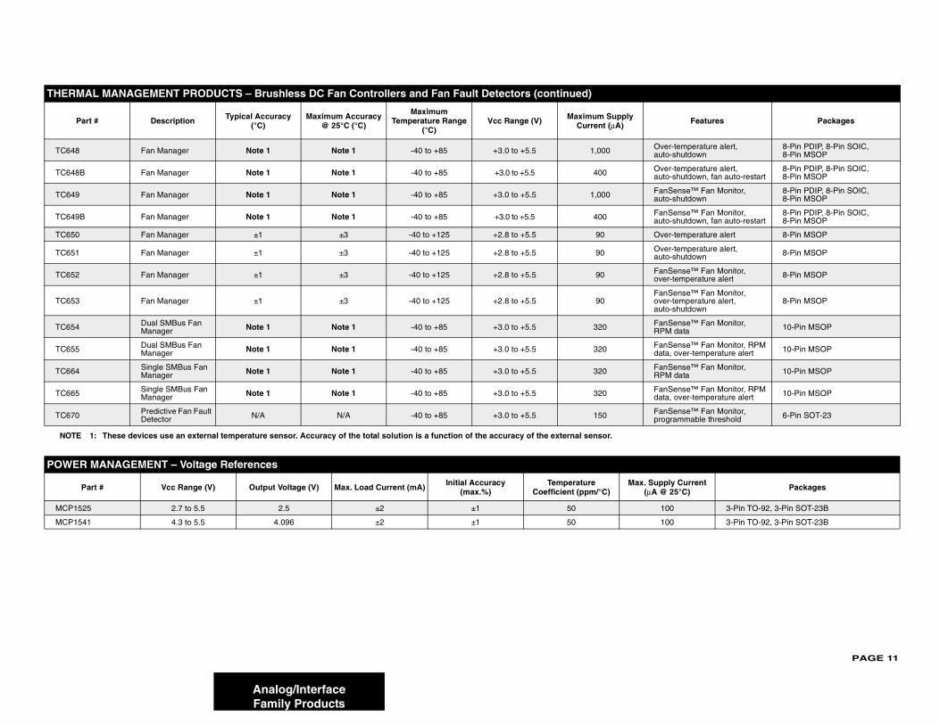
AL MANAGEMENT PRODUCTS – Brushless DC Fan Controllers and Fan Fault Detectors
art # Description Typical Accuracy (°C)
Maximum Accuracy @ 25°C (°C)
Maximum Temperature Range
(°C)Vcc Range (V) Maximum Supply
Current (μA)
Fan Manager Note 1 Note 1 -40 to +85 +3.0 to +5.5 1,000 Fm
B Fan Manager Note 1 Note 1 -40 to +85 +3.0 to +5.5 400Fma
Fan Manager Note 1 Note 1 -40 to +85 +3.0 to +5.5 1,000 Fa
B Fan Manager Note 1 Note 1 -40 to +85 +3.0 to +5.5 400 Fa
Fan Manager Note 1 Note 1 -40 to +85 +3.0 to +5.5 1,000 Fm
B Fan Manager Note 1 Note 1 -40 to +85 +3.0 to +5.5 400Fma
1: These devices use an external temperature sensor. Accuracy of the total solution is a function of the accuracy of the external sensor.
AL MANAGEMENT PRODUCTS – Temperature Sensors (continued)
art # Typical Accuracy (°C)
Maximum Accuracy @ 25°C (°C)
Maximum Temperature Range
(°C)VCC Range (V) Maximum Supply
Current (μA) Feature
1: These devices use an external temperature sensor. Accuracy of the total solution is a function of the accuracy of the external sensor.2: TCN75 idle current is 250 μA. This device also has a Software Shutdown mode that reduces supply current to <1 μA.3: MCP9805 max. accuracy measured at 85°C.
PAGE 11
TC64 Over-temperature alert, auto-shutdown
8-Pin PDIP, 8-Pin SOIC, 8-Pin MSOP
TC64 Over-temperature alert, auto-shutdown, fan auto-restart
8-Pin PDIP, 8-Pin SOIC, 8-Pin MSOP
TC64 FanSense™ Fan Monitor, auto-shutdown
8-Pin PDIP, 8-Pin SOIC, 8-Pin MSOP
TC64 FanSense™ Fan Monitor, auto-shutdown, fan auto-restart
8-Pin PDIP, 8-Pin SOIC, 8-Pin MSOP
TC65 Over-temperature alert 8-Pin MSOP
TC65 Over-temperature alert, auto-shutdown 8-Pin MSOP
TC65 FanSense™ Fan Monitor, over-temperature alert 8-Pin MSOP
TC65FanSense™ Fan Monitor, over-temperature alert, auto-shutdown
8-Pin MSOP
TC65 FanSense™ Fan Monitor, RPM data 10-Pin MSOP
TC65 FanSense™ Fan Monitor, RPM data, over-temperature alert 10-Pin MSOP
TC66 FanSense™ Fan Monitor, RPM data 10-Pin MSOP
TC66 FanSense™ Fan Monitor, RPM data, over-temperature alert 10-Pin MSOP
TC67 FanSense™ Fan Monitor, programmable threshold 6-Pin SOT-23
POWE
upply Current @ 25°C) Packages
MCP1 100 3-Pin TO-92, 3-Pin SOT-23B
MCP1 100 3-Pin TO-92, 3-Pin SOT-23B
THER
Features Packages
NOT
Analog/InterfaceFamily Products
8 Fan Manager Note 1 Note 1 -40 to +85 +3.0 to +5.5 1,000
8B Fan Manager Note 1 Note 1 -40 to +85 +3.0 to +5.5 400
9 Fan Manager Note 1 Note 1 -40 to +85 +3.0 to +5.5 1,000
9B Fan Manager Note 1 Note 1 -40 to +85 +3.0 to +5.5 400
0 Fan Manager ±1 ±3 -40 to +125 +2.8 to +5.5 90
1 Fan Manager ±1 ±3 -40 to +125 +2.8 to +5.5 90
2 Fan Manager ±1 ±3 -40 to +125 +2.8 to +5.5 90
3 Fan Manager ±1 ±3 -40 to +125 +2.8 to +5.5 90
4 Dual SMBus Fan Manager Note 1 Note 1 -40 to +85 +3.0 to +5.5 320
5 Dual SMBus Fan Manager Note 1 Note 1 -40 to +85 +3.0 to +5.5 320
4 Single SMBus Fan Manager Note 1 Note 1 -40 to +85 +3.0 to +5.5 320
5 Single SMBus Fan Manager Note 1 Note 1 -40 to +85 +3.0 to +5.5 320
0 Predictive Fan Fault Detector N/A N/A -40 to +85 +3.0 to +5.5 150
R MANAGEMENT – Voltage References
Part # Vcc Range (V) Output Voltage (V) Max. Load Current (mA) Initial Accuracy (max.%)
Temperature Coefficient (ppm/°C)
Max. S(μA
525 2.7 to 5.5 2.5 ±2 ±1 50
541 4.3 to 5.5 4.096 ±2 ±1 50
MAL MANAGEMENT PRODUCTS – Brushless DC Fan Controllers and Fan Fault Detectors (continued)
Part # Description Typical Accuracy (°C)
Maximum Accuracy @ 25°C (°C)
Maximum Temperature Range
(°C)Vcc Range (V) Maximum Supply
Current (μA)
E 1: These devices use an external temperature sensor. Accuracy of the total solution is a function of the accuracy of the external sensor.
PAGE 12
Analog/Interface
POWE
Part Features Packages
50 mA to
TC201 hutdown, Reference bypass input 5-Pin SOT-23A
TC101 hutdown, Reference bypass input 5-Pin SOT-23A
TC205 hutdown, Error output 5-Pin SOT-23A
TC105 hutdown, Error output 5-Pin SOT-23A
TC107 hutdown, Adjustable 5-Pin SOT-23A
TC107 hutdown, Reference bypass put, Error output 6-Pin SOT-23A
TC122 hutdown 5-Pin SOT-23A
TC101 hutdown 5-Pin SC-70
TC201 hutdown, Reference bypass input 5-Pin SOT-23A
TC101 hutdown, Reference bypass input 5-Pin SOT-23A
TC205 hutdown, Error output 5-Pin SOT-23A
TC105 hutdown, Error output 5-Pin SOT-23A
TC107 hutdown, Adjustable 5-Pin SOT-23A
TC107 hutdown, Reference bypass put, Error output 6-Pin SOT-23A
TC122 hutdown 5-Pin SOT-23A
TC118 hutdown 5-Pin SOT-23A
TC118 hutdown 5-Pin SOT-23A
TC218 hutdown, Reference bypass input 5-Pin SOT-23A
TC118 hutdown, Reference bypass input 5-Pin SOT-23A
TC218 hutdown, Error output 5-Pin SOT-23A
TC118 hutdown, Error output 5-Pin SOT-23A
TC118 hutdown, Adjustable 5-Pin SOT-23A
TC101 hutdown 5-Pin SOT-23A, 5-Pin SC-70
MCP1 0 μF ceramic cap stable, hort-circuit protection
3-Pin TO-92, 3-Pin SOT-23A, 3-Pin SOT-89
MCP1 V max. input voltage 3-Pin SOT-23A, 3-Pin SOT-89, 3-Pin TO-92
NOTE
Family Products
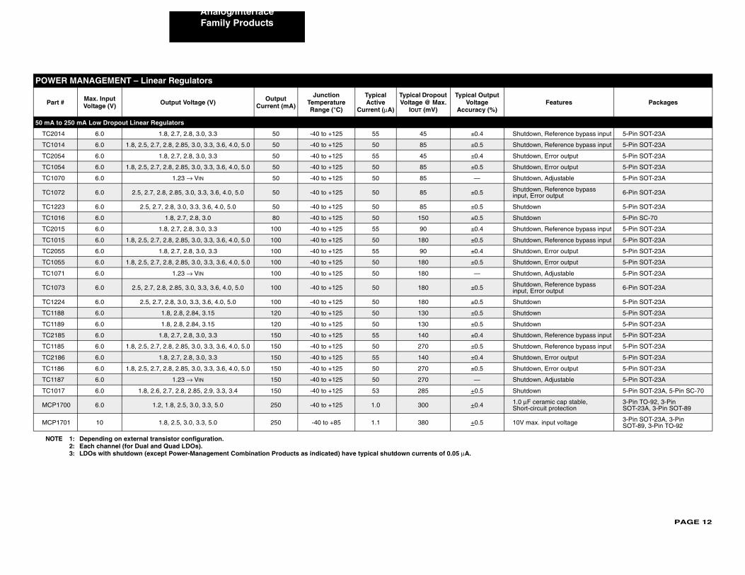
R MANAGEMENT – Linear Regulators
# Max. Input Voltage (V) Output Voltage (V) Output
Current (mA)
Junction Temperature Range (°C)
Typical Active
Current (μA)
Typical Dropout Voltage @ Max.
IOUT (mV)
Typical Output Voltage
Accuracy (%)
250 mA Low Dropout Linear Regulators
4 6.0 1.8, 2.7, 2.8, 3.0, 3.3 50 -40 to +125 55 45 ±0.4 S
4 6.0 1.8, 2.5, 2.7, 2.8, 2.85, 3.0, 3.3, 3.6, 4.0, 5.0 50 -40 to +125 50 85 ±0.5 S
4 6.0 1.8, 2.7, 2.8, 3.0, 3.3 50 -40 to +125 55 45 ±0.4 S
4 6.0 1.8, 2.5, 2.7, 2.8, 2.85, 3.0, 3.3, 3.6, 4.0, 5.0 50 -40 to +125 50 85 ±0.5 S
0 6.0 1.23 → VIN 50 -40 to +125 50 85 — S
2 6.0 2.5, 2.7, 2.8, 2.85, 3.0, 3.3, 3.6, 4.0, 5.0 50 -40 to +125 50 85 ±0.5 Sin
3 6.0 2.5, 2.7, 2.8, 3.0, 3.3, 3.6, 4.0, 5.0 50 -40 to +125 50 85 ±0.5 S
6 6.0 1.8, 2.7, 2.8, 3.0 80 -40 to +125 50 150 ±0.5 S
5 6.0 1.8, 2.7, 2.8, 3.0, 3.3 100 -40 to +125 55 90 ±0.4 S
5 6.0 1.8, 2.5, 2.7, 2.8, 2.85, 3.0, 3.3, 3.6, 4.0, 5.0 100 -40 to +125 50 180 ±0.5 S
5 6.0 1.8, 2.7, 2.8, 3.0, 3.3 100 -40 to +125 55 90 ±0.4 S
5 6.0 1.8, 2.5, 2.7, 2.8, 2.85, 3.0, 3.3, 3.6, 4.0, 5.0 100 -40 to +125 50 180 ±0.5 S
1 6.0 1.23 → VIN 100 -40 to +125 50 180 — S
3 6.0 2.5, 2.7, 2.8, 2.85, 3.0, 3.3, 3.6, 4.0, 5.0 100 -40 to +125 50 180 ±0.5 Sin
4 6.0 2.5, 2.7, 2.8, 3.0, 3.3, 3.6, 4.0, 5.0 100 -40 to +125 50 180 ±0.5 S
8 6.0 1.8, 2.8, 2.84, 3.15 120 -40 to +125 50 130 ±0.5 S
9 6.0 1.8, 2.8, 2.84, 3.15 120 -40 to +125 50 130 ±0.5 S
5 6.0 1.8, 2.7, 2.8, 3.0, 3.3 150 -40 to +125 55 140 ±0.4 S
5 6.0 1.8, 2.5, 2.7, 2.8, 2.85, 3.0, 3.3, 3.6, 4.0, 5.0 150 -40 to +125 50 270 ±0.5 S
6 6.0 1.8, 2.7, 2.8, 3.0, 3.3 150 -40 to +125 55 140 ±0.4 S
6 6.0 1.8, 2.5, 2.7, 2.8, 2.85, 3.0, 3.3, 3.6, 4.0, 5.0 150 -40 to +125 50 270 ±0.5 S
7 6.0 1.23 → VIN 150 -40 to +125 50 270 — S
7 6.0 1.8, 2.6, 2.7, 2.8, 2.85, 2.9, 3.3, 3.4 150 -40 to +125 53 285 +0.5 S
700 6.0 1.2, 1.8, 2.5, 3.0, 3.3, 5.0 250 -40 to +125 1.0 300 +0.4 1.S
701 10 1.8, 2.5, 3.0, 3.3, 5.0 250 -40 to +85 1.1 380 +0.5 10
1: Depending on external transistor configuration.2: Each channel (for Dual and Quad LDOs).3: LDOs with shutdown (except Power-Management Combination Products as indicated) have typical shutdown currents of 0.05 μA.
PAGE 13
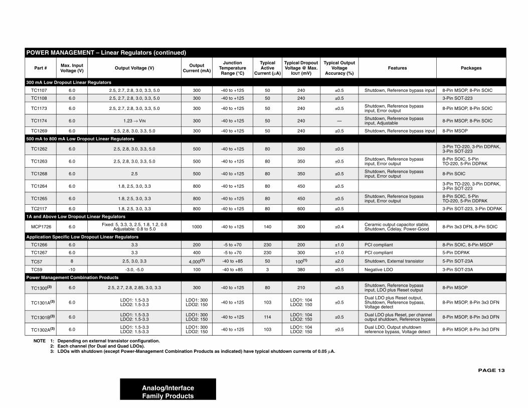
300 mA
TC110 hutdown, Reference bypass input 8-Pin MSOP, 8-Pin SOIC
TC110 3-Pin SOT-223
TC117 hutdown, Reference bypass put, Error output 8-Pin MSOP, 8-Pin SOIC
TC117 hutdown, Reference bypass put, Adjustable 8-Pin MSOP, 8-Pin SOIC
TC12 hutdown, Reference bypass input 8-Pin MSOP
500 mA
TC12 3-Pin TO-220, 3-Pin DDPAK, 3-Pin SOT-223
TC12 hutdown, Reference bypass put, Error output
8-Pin SOIC, 5-Pin TO-220, 5-Pin DDPAK
TC12 hutdown, Reference bypass put, Error output 8-Pin SOIC
TC12 3-Pin TO-220, 3-Pin DDPAK, 3-Pin SOT-223
TC12 hutdown, Reference bypass put, Error output
8-Pin SOIC, 5-Pin TO-220, 5-Pin DDPAK
TC211 3-Pin SOT-223, 3-Pin DDPAK
1A and
MCP1 eramic output capacitor stable, hutdown, Cdelay, Power-Good 8-Pin 3x3 DFN, 8-Pin SOIC
Applica
TC12 CI compliant 8-Pin SOIC, 8-Pin MSOP
TC12 CI compliant 5-Pin DDPAK
TC57 hutdown, External transistor 5-Pin SOT-23A
TC59 egative LDO 3-Pin SOT-23A
Power M
TC13hutdown, Reference bypass put, LDO plus Reset output 8-Pin MSOP
TC13ual LDO plus Reset output, hutdown, Reference bypass, oltage detect
8-Pin MSOP, 8-Pin 3x3 DFN
TC13ual LDO plus Reset, per channel utput shutdown, Reference bypass 8-Pin MSOP, 8-Pin 3x3 DFN
TC13ual LDO, Output shutdown ference bypass, Voltage detect 8-Pin MSOP, 8-Pin 3x3 DFN
POWE
Part Features Packages
NOT
Analog/InterfaceFamily Products
Low Dropout Linear Regulators
7 6.0 2.5, 2.7, 2.8, 3.0, 3.3, 5.0 300 -40 to +125 50 240 ±0.5 S
8 6.0 2.5, 2.7, 2.8, 3.0, 3.3, 5.0 300 -40 to +125 50 240 ±0.5
3 6.0 2.5, 2.7, 2.8, 3.0, 3.3, 5.0 300 -40 to +125 50 240 ±0.5 Sin
4 6.0 1.23 → VIN 300 -40 to +125 50 240 — Sin
69 6.0 2.5, 2.8, 3.0, 3.3, 5.0 300 -40 to +125 50 240 ±0.5 S
to 800 mA Low Dropout Linear Regulators
62 6.0 2.5, 2.8, 3.0, 3.3, 5.0 500 -40 to +125 80 350 ±0.5
63 6.0 2.5, 2.8, 3.0, 3.3, 5.0 500 -40 to +125 80 350 ±0.5 Sin
68 6.0 2.5 500 -40 to +125 80 350 ±0.5 Sin
64 6.0 1.8, 2.5, 3.0, 3.3 800 -40 to +125 80 450 ±0.5
65 6.0 1.8, 2.5, 3.0, 3.3 800 -40 to +125 80 450 ±0.5 Sin
7 6.0 1.8, 2.5, 3.0, 3.3 800 -40 to +125 80 600 ±0.5
Above Low Dropout Linear Regulators
726 6.0 Fixed: 5, 3.3, 3, 2.5, 1.8, 1.2, 0.8Adjustable: 0.8 to 5.0 1000 -40 to +125 140 300 ±0.4 C
S
tion Specific Low Dropout Linear Regulators
66 6.0 3.3 200 -5 to +70 230 200 ±1.0 P
67 6.0 3.3 400 -5 to +70 230 300 ±1.0 P
8 2.5, 3.0, 3.3 4,000(1) -40 to +85 50 100(1) ±2.0 S
-10 -3.0, -5.0 100 -40 to +85 3 380 ±0.5 N
anagement Combination Products
00(3) 6.0 2.5, 2.7, 2.8, 2.85, 3.0, 3.3 300 -40 to +125 80 210 ±0.5 Sin
01A(3) 6.0 LDO1: 1.5-3.3LDO2: 1.5-3.3
LDO1: 300LDO2: 150 -40 to +125 103 LDO1: 104
LDO2: 150 ±0.5DSV
01B(3) 6.0 LDO1: 1.5-3.3LDO2: 1.5-3.3
LDO1: 300LDO2: 150 -40 to +125 114 LDO1: 104
LDO2: 150 ±0.5 Do
02A(3) 6.0 LDO1: 1.5-3.3LDO2: 1.5-3.3
LDO1: 300LDO2: 150 -40 to +125 103 LDO1: 104
LDO2: 150 ±0.5 Dre
R MANAGEMENT – Linear Regulators (continued)
# Max. Input Voltage (V) Output Voltage (V) Output
Current (mA)
Junction Temperature Range (°C)
Typical Active
Current (μA)
Typical Dropout Voltage @ Max.
IOUT (mV)
Typical Output Voltage
Accuracy (%)
E 1: Depending on external transistor configuration.2: Each channel (for Dual and Quad LDOs).3: LDOs with shutdown (except Power-Management Combination Products as indicated) have typical shutdown currents of 0.05 μA.
PAGE 14
Analog/Interface
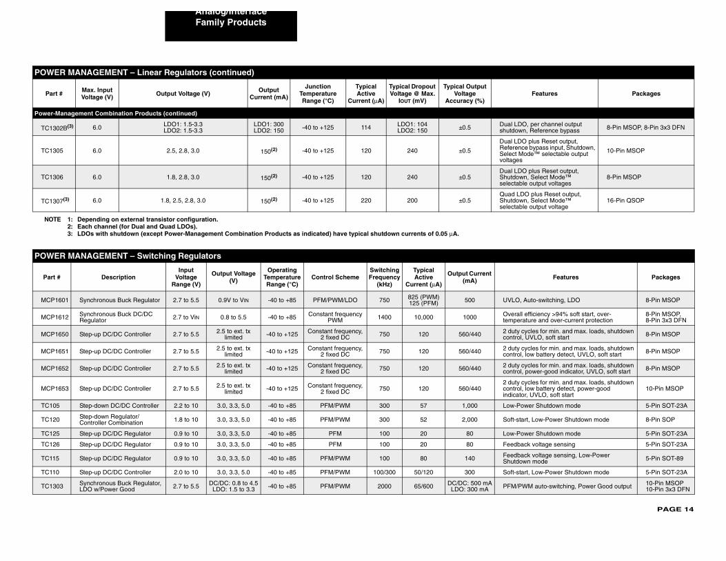
Power-M
TC130ual LDO, per channel output utdown, Reference bypass 8-Pin MSOP, 8-Pin 3x3 DFN
TC130
ual LDO plus Reset output, eference bypass input, Shutdown, elect Mode™ selectable output ltages
10-Pin MSOP
TC130ual LDO plus Reset output, hutdown, Select Mode™ lectable output voltages
8-Pin MSOP
TC130uad LDO plus Reset output, hutdown, Select Mode™ lectable output voltage
16-Pin QSOP
POWE
Part # Features Packages
MCP1 VLO, Auto-switching, LDO 8-Pin MSOP
MCP1 verall efficiency >94% soft start, over-emperature and over-current protection
8-Pin MSOP, 8-Pin 3x3 DFN
MCP1 duty cycles for min. and max. loads, shutdown ontrol, UVLO, soft start 8-Pin MSOP
MCP1 duty cycles for min. and max. loads, shutdown ontrol, low battery detect, UVLO, soft start 8-Pin MSOP
MCP1 duty cycles for min. and max. loads, shutdown ontrol, power-good indicator, UVLO, soft start 8-Pin MSOP
MCP1 duty cycles for min. and max. loads, shutdown ontrol, low battery detect, power-good
ndicator, UVLO, soft start10-Pin MSOP
TC105 ow-Power Shutdown mode 5-Pin SOT-23A
TC120 oft-start, Low-Power Shutdown mode 8-Pin SOP
TC125 ow-Power Shutdown mode 5-Pin SOT-23A
TC126 eedback voltage sensing 5-Pin SOT-23A
TC115 eedback voltage sensing, Low-Power hutdown mode 5-Pin SOT-89
TC110 oft-start, Low-Power Shutdown mode 5-Pin SOT-23A
TC130 FM/PWM auto-switching, Power Good output 10-Pin MSOP 10-Pin 3x3 DFN
POWE
Part Features Packages
NOTE
Family Products
anagement Combination Products (continued)
2B(3) 6.0 LDO1: 1.5-3.3LDO2: 1.5-3.3
LDO1: 300LDO2: 150 -40 to +125 114 LDO1: 104
LDO2: 150 ±0.5 Dsh
5 6.0 2.5, 2.8, 3.0 150(2) -40 to +125 120 240 ±0.5
DRSvo
6 6.0 1.8, 2.8, 3.0 150(2) -40 to +125 120 240 ±0.5DSse
7(3) 6.0 1.8, 2.5, 2.8, 3.0 150(2) -40 to +125 220 200 ±0.5QSse
R MANAGEMENT – Switching Regulators
DescriptionInput
Voltage Range (V)
Output Voltage (V)
Operating Temperature Range (°C)
Control SchemeSwitching Frequency
(kHz)
Typical Active
Current (μA)
Output Current (mA)
601 Synchronous Buck Regulator 2.7 to 5.5 0.9V to VIN -40 to +85 PFM/PWM/LDO 750 825 (PWM) 125 (PFM) 500 U
612 Synchronous Buck DC/DC Regulator 2.7 to ViN 0.8 to 5.5 -40 to +85 Constant frequency
PWM 1400 10,000 1000 Ot
650 Step-up DC/DC Controller 2.7 to 5.5 2.5 to ext. tx limited -40 to +125 Constant frequency,
2 fixed DC 750 120 560/440 2c
651 Step-up DC/DC Controller 2.7 to 5.5 2.5 to ext. tx limited -40 to +125 Constant frequency,
2 fixed DC 750 120 560/440 2c
652 Step-up DC/DC Controller 2.7 to 5.5 2.5 to ext. tx limited -40 to +125 Constant frequency,
2 fixed DC 750 120 560/440 2c
653 Step-up DC/DC Controller 2.7 to 5.5 2.5 to ext. tx limited -40 to +125 Constant frequency,
2 fixed DC 750 120 560/4402ci
Step-down DC/DC Controller 2.2 to 10 3.0, 3.3, 5.0 -40 to +85 PFM/PWM 300 57 1,000 L
Step-down Regulator/Controller Combination 1.8 to 10 3.0, 3.3, 5.0 -40 to +85 PFM/PWM 300 52 2,000 S
Step-up DC/DC Regulator 0.9 to 10 3.0, 3.3, 5.0 -40 to +85 PFM 100 20 80 L
Step-up DC/DC Regulator 0.9 to 10 3.0, 3.3, 5.0 -40 to +85 PFM 100 20 80 F
Step-up DC/DC Regulator 0.9 to 10 3.0, 3.3, 5.0 -40 to +85 PFM/PWM 100 80 140 FS
Step-up DC/DC Controller 2.0 to 10 3.0, 3.3, 5.0 -40 to +85 PFM/PWM 100/300 50/120 300 S
3 Synchronous Buck Regulator, LDO w/Power Good 2.7 to 5.5 DC/DC: 0.8 to 4.5
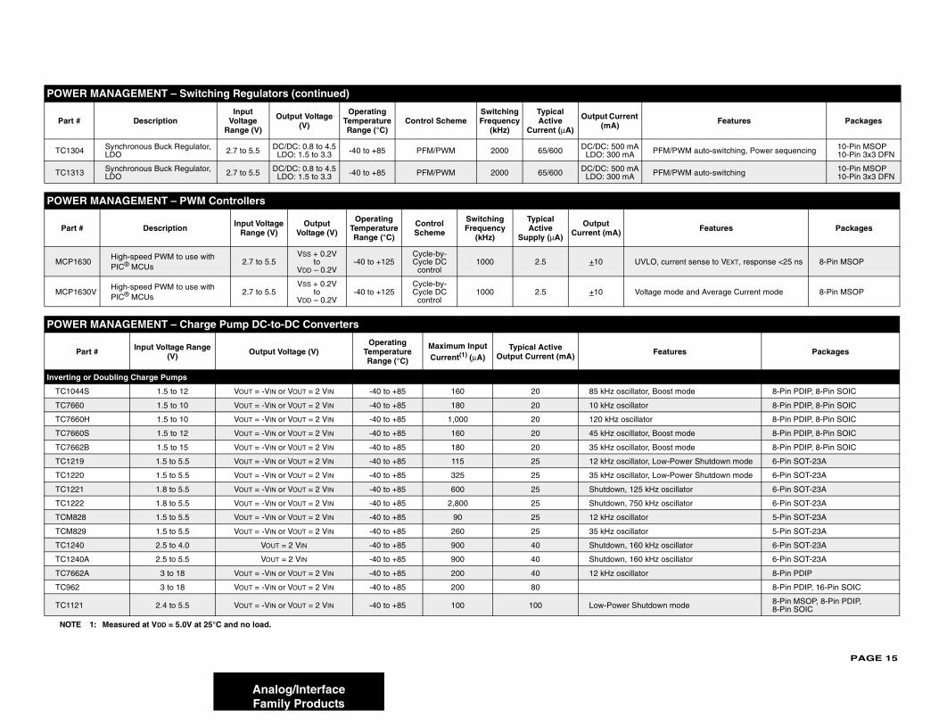
LDO: 1.5 to 3.3 -40 to +85 PFM/PWM 2000 65/600 DC/DC: 500 mALDO: 300 mA P
R MANAGEMENT – Linear Regulators (continued)
# Max. Input Voltage (V) Output Voltage (V) Output
Current (mA)
Junction Temperature Range (°C)
Typical Active
Current (μA)
Typical Dropout Voltage @ Max.
IOUT (mV)
Typical Output Voltage
Accuracy (%)
1: Depending on external transistor configuration.2: Each channel (for Dual and Quad LDOs).3: LDOs with shutdown (except Power-Management Combination Products as indicated) have typical shutdown currents of 0.05 μA.
PAGE 15
TC13 PFM/PWM auto-switching, Power sequencing 10-Pin MSOP 10-Pin 3x3 DFN
TC13 PFM/PWM auto-switching 10-Pin MSOP 10-Pin 3x3 DFN
POWE
Part Features Packages
MCP1 , current sense to VEXT, response <25 ns 8-Pin MSOP
MCP1 ge mode and Average Current mode 8-Pin MSOP
POWE
Features Packages
Invertin
TC10 Boost mode 8-Pin PDIP, 8-Pin SOIC
TC76 8-Pin PDIP, 8-Pin SOIC
TC76 8-Pin PDIP, 8-Pin SOIC
TC76 Boost mode 8-Pin PDIP, 8-Pin SOIC
TC76 Boost mode 8-Pin PDIP, 8-Pin SOIC
TC12 Low-Power Shutdown mode 6-Pin SOT-23A
TC12 Low-Power Shutdown mode 6-Pin SOT-23A
TC12 z oscillator 6-Pin SOT-23A
TC12 z oscillator 6-Pin SOT-23A
TCM8 5-Pin SOT-23A
TCM8 5-Pin SOT-23A
TC12 z oscillator 6-Pin SOT-23A
TC12 z oscillator 6-Pin SOT-23A
TC76 8-Pin PDIP
TC96 8-Pin PDIP, 16-Pin SOIC
TC112 own mode 8-Pin MSOP, 8-Pin PDIP, 8-Pin SOIC
NOT
POWE
Part Features Packages
Analog/InterfaceFamily Products
04 Synchronous Buck Regulator, LDO 2.7 to 5.5 DC/DC: 0.8 to 4.5
LDO: 1.5 to 3.3 -40 to +85 PFM/PWM 2000 65/600 DC/DC: 500 mALDO: 300 mA
13 Synchronous Buck Regulator, LDO 2.7 to 5.5 DC/DC: 0.8 to 4.5
LDO: 1.5 to 3.3 -40 to +85 PFM/PWM 2000 65/600 DC/DC: 500 mALDO: 300 mA
R MANAGEMENT – PWM Controllers
# Description Input Voltage Range (V)
Output Voltage (V)
Operating Temperature Range (°C)
Control Scheme
Switching Frequency
(kHz)
Typical Active
Supply (μA)
Output Current (mA)
630High-speed PWM to use with PIC® MCUs
2.7 to 5.5VSS + 0.2V
toVDD – 0.2V
-40 to +125Cycle-by-Cycle DC
control1000 2.5 +10 UVLO
630VHigh-speed PWM to use with PIC® MCUs
2.7 to 5.5VSS + 0.2V
toVDD – 0.2V
-40 to +125Cycle-by-Cycle DC
control1000 2.5 +10 Volta
R MANAGEMENT – Charge Pump DC-to-DC Converters
Part # Input Voltage Range (V) Output Voltage (V)
Operating Temperature Range (°C)
Maximum Input Current(1) (μA)
Typical Active Output Current (mA)
g or Doubling Charge Pumps
44S 1.5 to 12 VOUT = -VIN or VOUT = 2 VIN -40 to +85 160 20 85 kHz oscillator,
60 1.5 to 10 VOUT = -VIN or VOUT = 2 VIN -40 to +85 180 20 10 kHz oscillator
60H 1.5 to 10 VOUT = -VIN or VOUT = 2 VIN -40 to +85 1,000 20 120 kHz oscillator
60S 1.5 to 12 VOUT = -VIN or VOUT = 2 VIN -40 to +85 160 20 45 kHz oscillator,
62B 1.5 to 15 VOUT = -VIN or VOUT = 2 VIN -40 to +85 180 20 35 kHz oscillator,
19 1.5 to 5.5 VOUT = -VIN or VOUT = 2 VIN -40 to +85 115 25 12 kHz oscillator,
20 1.5 to 5.5 VOUT = -VIN or VOUT = 2 VIN -40 to +85 325 25 35 kHz oscillator,
21 1.8 to 5.5 VOUT = -VIN or VOUT = 2 VIN -40 to +85 600 25 Shutdown, 125 kH
22 1.8 to 5.5 VOUT = -VIN or VOUT = 2 VIN -40 to +85 2,800 25 Shutdown, 750 kH
28 1.5 to 5.5 VOUT = -VIN or VOUT = 2 VIN -40 to +85 90 25 12 kHz oscillator
29 1.5 to 5.5 VOUT = -VIN or VOUT = 2 VIN -40 to +85 260 25 35 kHz oscillator
40 2.5 to 4.0 VOUT = 2 VIN -40 to +85 900 40 Shutdown, 160 kH
40A 2.5 to 5.5 VOUT = 2 VIN -40 to +85 900 40 Shutdown, 160 kH
62A 3 to 18 VOUT = -VIN or VOUT = 2 VIN -40 to +85 200 40 12 kHz oscillator
2 3 to 18 VOUT = -VIN or VOUT = 2 VIN -40 to +85 200 80
1 2.4 to 5.5 VOUT = -VIN or VOUT = 2 VIN -40 to +85 100 100 Low-Power Shutd
E 1: Measured at VDD = 5.0V at 25°C and no load.
R MANAGEMENT – Switching Regulators (continued)
# DescriptionInput
Voltage Range (V)
Output Voltage (V)
Operating Temperature Range (°C)
Control SchemeSwitching Frequency
(kHz)
Typical Active
Current (μA)
Output Current (mA)
PAGE 16
Analog/Interface
Multi-Fu
TCM6 m +3V or ±10V from +5V 8-Pin PDIP, 8-Pin SOIC
Inverting
TC682 8-Pin PDIP, 8-Pin SOIC
Regulate
MCP1 t, 650 kHz oscillator 8-Pin MSOP
MCP1 t, 1 MHz oscillator 8-Pin MSOP
POWE
Part # dditional Features Packages Bond
Options
MCP1 3-Pin SOT-23B, 3-Pin SC-70, 3-Pin TO-92 N/A
MCP1 x. 809 Pinout 3-Pin SOT-23B, 3-Pin SC-70, 3-Pin TO-92 N/A
TC127 3-Pin SOT-23B N/A
TC127 3-Pin SOT-23B N/A
TCM8 3-Pin SOT-23B, 3-Pin SC-70 N/A
TC127 anual Reset 4-Pin SOT-143 N/A
TCM8 nual Reset 4-Pin SOT-143 N/A
MCP1 3-Pin TO-92, 3-Pin SOT-23B D, H
MCP8 3-Pin SOT-23B N/A
TC127 3-Pin SOT-23B N/A
TC127 3-Pin SOT-23B N/A
TCM8 3-Pin SOT-23B, 3-Pin SC-70 N/A
TC127 nual Reset 4-Pin SOT-143 N/A
TCM8 anual Reset 4-Pin SOT-143 N/A
MCP1 3-Pin TO-92, 3-Pin SOT-23B D, H
MCP8 3-Pin SOT-23B N/A
MCP1 3-Pin SOT-23B, 3-Pin SC-70, 3-Pin TO-92 N/A
TC127 3-Pin SOT-23B N/A
TC127 3-Pin SOT-23B N/A
POWE
P eatures Packages
NOTE
Family Products
nction Charge Pumps
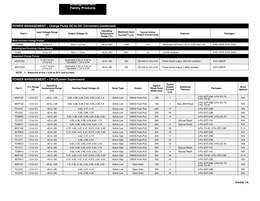
80 2.0 to 5.5 VOUT = ±2 VIN -40 to +85 1,000 ±10 Generates ±6V fro
and Doubling Charge Pumps
2.4 to 5.5 VOUT = -2 VIN -40 to +85 400 10 12 kHz oscillator
d Charge Pumps
252 2.1/2.7 to 5.52.0 to 5.5
Selectable 3.3V or 5.0V or Adjustable 1.5V to 5.5V -40 to +85 120 120 mA for VIN>3.0V Power-Good outpu
253 2.1/2.7 to 5.52.0 to 5.5
Selectable 3.3V or 5.0V or Adjustable 1.5V to 5.5V -40 to +85 120 120 mA for VIN>3.0V Power-Good outpu
R MANAGEMENT – CPU/System Supervisors
VCC Range (V)
Operating Temperature Range
(°C)Nominal Reset Voltage (V) Reset Type Output
Typical Reset Pulse Width (ms)
Typical Supply Current
(μA)
A
02 1.0 to 5.5 -40 to +125 4.63, 4.38, 3.08, 2.93, 2.63, 2.32, 1.9 Active Low CMOS Push-Pull 120 1
03 1.0 to 5.5 -40 to +125 4.63, 4.38, 3.08, 2.93, 2.63, 2.32, 1.9 Active Low CMOS Push-Pull 120 1 Ma
2 1.2 to 5.5 -40 to +85 4.62, 4.37, 4.12 Active Low CMOS Push-Pull 200 17
5 1.2 to 5.5 -40 to +85 3.06, 2.88, 2.55 Active Low CMOS Push-Pull 200 20
09 1.2 to 5.5 -40 to +85 4.63, 4.38, 4.00, 3.08, 2.93, 2.63, 2.32 Active Low CMOS Push-Pull 240 12
0 1.2 to 5.5 -40 to +85 4.63, 4.38, 3.08, 2.93, 2.63, 1.75 Active Low CMOS Push-Pull 280 7 M
11 1.0 to 5.5 -40 to +85 4.63, 4.38, 3.08, 2.93, 2.63, 1.75 Active Low CMOS Push-Pull 280 6 Ma
00 1.0 to 5.5 -40 to +85 4.72, 4.62, 4.47, 4.37, 3.075, 2.92, 2.62 Active Low CMOS Push-Pull 350 45
09 1.0 to 5.5 -40 to +85 4.72, 4.62, 4.47, 4.37, 3.075, 2.92, 2.62 Active Low CMOS Push-Pull 350 45
4 1.8 to 5.5 -40 to +85 4.62, 4.37, 4.13 Active High CMOS Push-Pull 200 17
7 1.8 to 5.5 -40 to +85 3.06, 2.88, 2.55 Active High CMOS Push-Pull 200 20
10 1.2 to 5.5 -40 to +85 4.63, 4.38, 3.08, 2.93, 2.63, 2.32 Active High CMOS Push-Pull 240 12
1 1.2 to 5.5 -40 to +85 4.63, 4.38, 3.08, 2.93, 2.63, 1.75 Active High CMOS Push-Pull 280 7 Ma
12 1.1 to 5.5 -40 to +85 4.63, 4.38, 3.08, 2.93, 2.63, 1.75 Active High CMOS Push-Pull 280 6 M
01 1.0 to 5.5 -40 to +85 4.72, 4.62, 4.47, 4.37, 3.075, 2.92, 2.62 Active High CMOS Push-Pull 350 45
10 1.0 to 5.5 -40 to +85 4.72, 4.62, 4.47, 4.37, 3.075, 2.92, 2.62 Active High CMOS Push-Pull 350 45
21 1.0 to 5.5 -40 to +125 1.9, 2.32, 2, 63, 2.93, 3.08, 4.38, 4.63 Active Low Open-drain 120 1
3 1.2 to 5.5 -40 to +85 4.62, 4.37, 4.12 Active Low Open-drain 200 17
6 1.2 to 5.5 -40 to +85 3.06, 2.88, 2.55 Active Low Open-drain 200 20
R MANAGEMENT – Charge Pump DC-to-DC Converters (continued)
art # Input Voltage Range (V) Output Voltage (V)
Operating Temperature Range (°C)
Maximum Input Current(1) (μA)
Typical Active Output Current (mA) F
1: Measured at VDD = 5.0V at 25°C and no load.
PAGE 17
MCP1 3-Pin TO-92, 3-Pin SOT-23, 8-Pin SOIC D, G, H
TC12 3-Pin SOT-23B N/A
MCP1 0kΩ Internal ll-up Resistor
3-Pin SOT-23B, 3-Pin SC-70, 3-Pin TO-92 N/A
MCP1 3-Pin TO-92, 3-Pin SOT-23, 8-Pin SOIC D, F, H
TC12 3-Pin SOT-23B N/A
TC12 tchdog Timer 8-Pin PDIP, 8-Pin SOIC, 16-Pin SOIC N/A
TC32 tchdog Timer 3-Pin TO-92, 3-Pin SOT-223 N/A
POWE
Part Features Packages
MCP1 3-Pin SOT-23B, 3-Pin TO-92, 3-Pin SC-70, 3-Pin SOT-89
MCP1 3-Pin SOT-23B, 3-Pin TO-92, 3-Pin SC-70, 3-Pin SOT-89
TC51 Reset delay 3-Pin SOT-23A
TC52 Dual channel 5-Pin SOT-23A
TC53 5-Pin SOT-23A
TC54 3-Pin SOT-23A, 3-Pin SOT-89, 3-Pin TO-92
POWE
P ay (td1, td2)(1) )
Packages
Low-Sid
TC14 0 8-Pin PDIP, 8-Pin SOIC, 8-Pin MSOP
TC14 0 8-Pin PDIP, 8-Pin SOIC, 8-Pin MSOP
TC14 0 8-Pin PDIP, 8-Pin SOIC, 8-Pin MSOP
TC14 0 8-Pin PDIP, 8-Pin SOIC, 8-Pin MSOP
TC14 5 8-Pin PDIP, 8-Pin SOIC
NOT
POWE
Part Additional Features Packages Bond
Options
Analog/InterfaceFamily Products
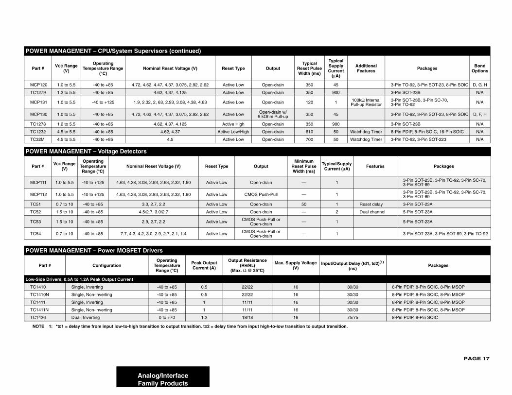
20 1.0 to 5.5 -40 to +85 4.72, 4.62, 4.47, 4.37, 3.075, 2.92, 2.62 Active Low Open-drain 350 45
79 1.2 to 5.5 -40 to +85 4.62, 4.37, 4.125 Active Low Open-drain 350 900
31 1.0 to 5.5 -40 to +125 1.9, 2.32, 2, 63, 2.93, 3.08, 4.38, 4.63 Active Low Open-drain 120 1 10Pu
30 1.0 to 5.5 -40 to +85 4.72, 4.62, 4.47, 4.37, 3.075, 2.92, 2.62 Active Low Open-drain w/5 kOhm Pull-up 350 45
78 1.2 to 5.5 -40 to +85 4.62, 4.37, 4.125 Active High Open-drain 350 900
32 4.5 to 5.5 -40 to +85 4.62, 4.37 Active Low/High Open-drain 610 50 Wa
M 4.5 to 5.5 -40 to +85 4.5 Active Low Open-drain 700 50 Wa
R MANAGEMENT – Voltage Detectors
# VCC Range (V)
Operating Temperature Range (°C)
Nominal Reset Voltage (V) Reset Type OutputMinimum
Reset Pulse Width (ms)
Typical Supply Current (μA)
11 1.0 to 5.5 -40 to +125 4.63, 4.38, 3.08, 2.93, 2.63, 2.32, 1.90 Active Low Open-drain — 1
12 1.0 to 5.5 -40 to +125 4.63, 4.38, 3.08, 2.93, 2.63, 2.32, 1.90 Active Low CMOS Push-Pull — 1
0.7 to 10 -40 to +85 3.0, 2.7, 2.2 Active Low Open-drain 50 1
1.5 to 10 -40 to +85 4.5/2.7, 3.0/2.7 Active Low Open-drain — 2
1.5 to 10 -40 to +85 2.9, 2.7, 2.2 Active Low CMOS Push-Pull or Open-drain — 1
0.7 to 10 -40 to +85 7.7, 4.3, 4.2, 3.0, 2.9, 2.7, 2.1, 1.4 Active Low CMOS Push-Pull or Open-drain — 1
R MANAGEMENT – Power MOSFET Drivers
art # ConfigurationOperating
Temperature Range (°C)
Peak Output Current (A)
Output Resistance (RH/RL)
(Max. Ω @ 25°C)
Max. Supply Voltage (V)
Input/Output Del(ns
e Drivers, 0.5A to 1.2A Peak Output Current
10 Single, Inverting -40 to +85 0.5 22/22 16 30/3
10N Single, Non-inverting -40 to +85 0.5 22/22 16 30/3
11 Single, Inverting -40 to +85 1 11/11 16 30/3
11N Single, Non-inverting -40 to +85 1 11/11 16 30/3
26 Dual, Inverting 0 to +70 1.2 18/18 16 75/7
E 1: *tD1 = delay time from input low-to-high transition to output transition. tD2 = delay time from input high-to-low transition to output transition.
R MANAGEMENT – CPU/System Supervisors (continued)
# VCC Range (V)
Operating Temperature Range
(°C)Nominal Reset Voltage (V) Reset Type Output
Typical Reset Pulse Width (ms)
Typical Supply Current
(μA)
PAGE 18
Analog/Interface
Low-Sid
TC142 8-Pin PDIP, 8-Pin SOIC
TC142 8-Pin PDIP, 8-Pin SOIC
TC446 14-Pin PDIP, 16-Pin SOIC (W)
TC446 14-Pin PDIP, 16-Pin SOIC (W)
TC446 14-Pin PDIP, 16-Pin SOIC (W)
Low-Sid
TC440 8-Pin PDIP
TC442 8-Pin PDIP, 8-Pin SOIC, 8-Pin DFN
TC442 8-Pin PDIP, 8-Pin SOIC, 8-Pin DFN
TC442 8-Pin PDIP, 8-Pin SOIC, 8-Pin DFN
TC442 8-Pin PDIP, 8-Pin SOIC, 8-Pin DFN, 8-Pin MSOP
TC442 8-Pin PDIP, 8-Pin SOIC, 8-Pin DFN, 8-Pin MSOP
TC442 8-Pin PDIP, 8-Pin SOIC, 8-Pin DFN, 8-Pin MSOP
TC426 8-Pin PDIP, 8-Pin SOIC
TC427 8-Pin PDIP, 8-Pin SOIC
TC428 8-Pin PDIP, 8-Pin SOIC
TC440 8-Pin PDIP, 8-Pin SOIC
TC440 8-Pin PDIP, 8-Pin SOIC
Low-Sid
TC141 8-Pin PDIP, 8-Pin SOIC, 8-Pin MSOP
TC141 8-Pin PDIP, 8-Pin SOIC, 8-Pin MSOP
TC141 8-Pin PDIP, 8-Pin SOIC, 8-Pin MSOP
TC141 8-Pin PDIP, 8-Pin SOIC, 8-Pin MSOP
TC442 8-Pin PDIP, 16-Pin SOIC (W), 8-Pin DFN
TC442 8-Pin PDIP, 16-Pin SOIC (W), 8-Pin DFN
TC442 8-Pin PDIP, 16-Pin SOIC (W), 8-Pin DFN
TC429 8-Pin PDIP, 8-Pin DFN, 8-Pin SOIC
TC442 8-Pin PDIP, 8-Pin SOIC, 5-Pin TO-220, 8-Pin DFN
TC442 8-Pin PDIP, 8-Pin SOIC, 5-Pin TO-220, 8-Pin DFN
TC442 8-Pin PDIP, 5-Pin TO-220, 8-Pin DFN
TC442 8-Pin PDIP, 8-Pin SOIC, 5-Pin TO-220, 8-Pin 6x5 DFN
TC442 8-Pin PDIP, 5-Pin TO-220, 8-Pin DFN
POWE
Pa y (td1, td2)(1) Packages
NOTE
Family Products
e Drivers, 0.5A to 1.2A Peak Output Current (continued)
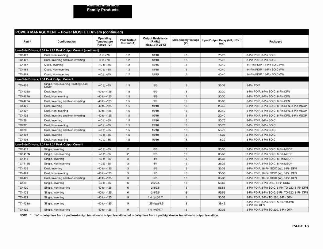
7 Dual, Non-inverting 0 to +70 1.2 18/18 16 75/75
8 Dual, Inverting and Non-inverting 0 to +70 1.2 18/18 16 75/75
7 Quad, Inverting -40 to +85 1.2 15/15 18 40/40
8 Quad, Non-inverting -40 to +85 1.2 15/15 18 40/40
9 Quad, Non-inverting -40 to +85 1.2 15/15 18 40/40
e Drivers, 1.5A Peak Output Current
3 Single, Non-inverting Floating Load Driver -40 to +85 1.5 5/5 18 33/38
6A Dual, Inverting -40 to +125 1.5 9/9 18 30/30
7A Dual, Non-inverting -40 to +125 1.5 9/9 18 30/30
8A Dual, Inverting and Non-inverting -40 to +125 1.5 9/9 18 30/30
6 Dual, Inverting -40 to +125 1.5 10/10 18 20/40
7 Dual, Non-inverting -40 to +125 1.5 10/10 18 20/40
8 Dual, Inverting and Non-inverting -40 to +125 1.5 10/10 18 20/40
Dual, Inverting -40 to +85 1.5 15/10 18 50/75
Dual, Non-inverting -40 to +85 1.5 15/10 18 50/75
Dual, Inverting and Non-inverting -40 to +85 1.5 15/10 18 50/75
4 Dual, Inverting -40 to +85 1.5 10/10 18 15/32
5 Dual, Non-inverting -40 to +85 1.5 10/10 18 15/32
e Drivers, 2.0A to 9.0A Peak Output Current
2 Single, Inverting -40 to +85 2 6/6 16 35/35
2N Single, Non-inverting -40 to +85 2 6/6 16 35/35
3 Single, Inverting -40 to +85 3 4/4 16 35/35
3N Single, Non-inverting -40 to +85 3 4/4 16 35/35
3 Dual, Inverting -40 to +125 3 5/5 18 33/38
4 Dual, Non-inverting -40 to +125 3 5/5 18 33/38
5 Dual, Inverting and Non-inverting -40 to +125 3 5/5 18 33/38
Single, Inverting -40 to +85 6 2.5/2.5 18 53/60
0 Single, Non-inverting -40 to +125 6 2.8/2.5 18 55/55
9 Single, Inverting -40 to +125 6 2.8/2.5 18 55/55
1 Single, Inverting -40 to +125 9 1.4 (typ)/1.7 18 30/33
1A Single, Inverting -40 to +125 9 1.25 (typ)/1.5 18 38/42
2 Single, Non-inverting -40 to +125 9 1.4 (typ)/1.7 18 30/33
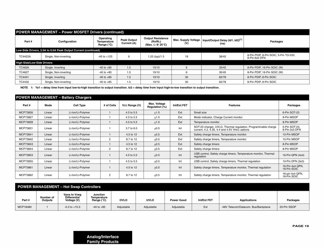
R MANAGEMENT – Power MOSFET Drivers (continued)
rt # ConfigurationOperating
Temperature Range (°C)
Peak Output Current (A)
Output Resistance (RH/RL)
(Max. Ω @ 25°C)
Max. Supply Voltage (V)
Input/Output Dela(ns)
1: *tD1 = delay time from input low-to-high transition to output transition. tD2 = delay time from input high-to-low transition to output transition.
PAGE 19
Low-Sid
TC44 2 8-Pin PDIP, 8-Pin SOIC, 5-Pin TO-220, 8-Pin 6x5 DFN
High-Si
TC46 5 8-Pin PDIP, 16-Pin SOIC (W)
TC46 5 8-Pin PDIP, 16-Pin SOIC (W)
TC44 8 8-Pin PDIP, 8-Pin SOIC
TC44 8 8-Pin PDIP, 8-Pin SOIC
POWE
Pa Features Packages
MCP7 6-Pin SOT-23
MCP7 urrent monitor 8-Pin MSOP
MCP7 8-Pin MSOP
MCP7 Thermal regulation, Programmable charge d 4.5V VREG options
5-Pin SOT-23, 8-Pin 2x3 DFN
MCP7 perature monitor 10-Pin MSOP
MCP7 perature monitor 10-Pin MSOP
MCP7 8-Pin MSOP
MCP7 8-Pin MSOP
MCP7 ge timers, Temperature monitor, Thermal 16-Pin QFN (4x4)
MCP7 ge timers, Thermal regulation 10-Pin DFN (3x3)
MCP7 perature monitor, Thermal regulation 16-Pin 4x4 QFN, 16-Pin SOIC
MCP7 perature monitor, Thermal regulation 16-pin 4x4 QFN,16-Pin SOIC
POW
Par Applications Packages
MCP18 8V Telecom/Datacom, Bus/Backplane 20-Pin SSOP
POWE
P ay (td1, td2)(1) )
Packages
NOT
Analog/InterfaceFamily Products
e Drivers, 2.0A to 9.0A Peak Output Current (continued)
22A Single, Non-inverting -40 to +125 9 1.25 (typ)/1.5 18 38/4
de/Low-Side Drivers
26 Single, Inverting -40 to +85 1.5 15/10 6 35/4
27 Single, Non-inverting -40 to +85 1.5 15/10 6 35/4
31 Single, Inverting -40 to +85 1.5 10/10 30 62/7
32 Single, Non-inverting -40 to +85 1.5 10/10 30 62/7
R MANAGEMENT – Battery Chargers
rt # Mode Cell Type # of Cells VCC Range (V) Max. Voltage Regulation (%) Int/Ext FET
3826 Linear Li-Ion/Li-Polymer 1 4.5 to 5.5 +1.0 Ext Small size
3827 Linear Li-Ion/Li-Polymer 1 4.5 to 5.5 +1.0 Ext Mode indicator, Charge C
3828 Linear Li-Ion/Li Polymer 1 4.5 to 5.5 +1.0 Ext Temperature monitor
3831 Linear Li-Ion/Li-Polymer 1 3.7 to 6.0 +0.5 Int SOT-23 charger, UVLO, current, 4.2, 4.35, 4.4 an
3841 Linear Li-Ion/Li-Polymer 1 4.5 to 12 +0.5 Ext Safety charge timers, Tem
3842 Linear Li-Ion/Li-Polymer 2 8.7 to 12 +0.5 Ext Safety charge timers, Tem
3843 Linear Li-Ion/Li-Polymer 1 4.5 to 12 +0.5 Ext Safety charge timers
3844 Linear Li-Ion/Li-Polymer 2 8.7 to 12 +0.5 Ext Safety charge timers
3853 Linear Li-Ion/Li-Polymer 1 4.5 to 5.5 +0.5 Int USB control, Safety charregulation
3855 Linear Li-Ion/Li-Polymer 1 4.5 to 5.5 +0.5 Int USB control, Safety char
3861 Linear Li-Ion/Li-Polymer 1 4.5 to 12 +0.5 Int Safety charge timers, Tem
3862 Linear Li-Ion/Li-Polymer 2 8.7 to 12 +0.5 Int Safety charge timers, Tem
ER MANAGEMENT – Hot Swap Controllers
t #Number of
Outputs
Vpos to Vneg Differential Voltage (V)
Junction Temperature Range (°C) OVLO UVLO Power Good Int/Ext FET
480 1 -0.3 to +15.0 -40 to +85 Adjustable Adjustable Adjustable Ext -4
R MANAGEMENT – Power MOSFET Drivers (continued)
art # ConfigurationOperating
Temperature Range (°C)
Peak Output Current (A)
Output Resistance (RH/RL)
(Max. Ω @ 25°C)
Max. Supply Voltage (V)
Input/Output Del(ns
E 1: *tD1 = delay time from input low-to-high transition to output transition. tD2 = delay time from input high-to-low transition to output transition.
PAGE 20
Analog/Interface
LINEA
Par Packages
TC103 5-Pin SOT-23A(R)
TC103 wn pin 6-Pin SOT-23A(R)
TC102 8-Pin PDIP, 8-Pin MSOP, 8-Pin SOIC
TC103 wn pins 16-Pin QSOP
MCP68-Pin PDIP, 8-Pin SOIC, 8-Pin MSOP, 5-Pin SOT-23(S)
MCP6 8-Pin PDIP, 8-Pin SOIC, 8-Pin MSOP
MCP6 elect 8-Pin PDIP, 8-Pin SOIC, 8-Pin MSOP
MCP6 14-Pin PDIP, 14-Pin SOIC, 14-Pin TSSOP
MCP6 stable 8-Pin PDIP, 8-Pin SOIC, 8-Pin MSOP
MCP6 stable 8-Pin PDIP, 8-Pin SOIC, 8-Pin MSOP
MCP6 stable, 8-Pin PDIP, 8-Pin SOIC, 8-Pin MSOP
MCP6 stable 14-Pin PDIP, 14-Pin SOIC, 14-Pin TSSOP
MCP68-Pin PDIP, 8-Pin SOIC, 8-Pin TSSOP, 5-Pin SOT23(S)
MCP6 8-Pin PDIP, 8-Pin SOIC, 8-Pin TSSOP
MCP6 8-Pin PDIP, 8-Pin SOIC, 8-Pin TSSOP
MCP6 14-Pin PDIP, 14-Pin SOIC, 14-Pin TSSOP
MCP6 8-Pin PDIP, 8-Pin SOIC, 8-Pin MSOP
MCP6 8-Pin PDIP, 8-Pin SOIC, 8-Pin MSOP
MCP6 PNP Input 8-Pin PDIP, 8-Pin SOIC, 8-Pin MSOP
MCP6 14-Pin PDIP, 14-Pin SOIC, 14-Pin TSSOP
MCP6 5-Pin SC-70(U), 5-Pin SOT-23(S,R,U), 8-Pin PDIP, 8-Pin SOIC, 8-Pin MSOP
MCP6 8-Pin PDIP, 8-Pin SOIC, 8-Pin MSOP
MCP6 14-Pin PDIP, 14-Pin SOIC, 14-Pin TSSOP
MCP6 5-Pin SC-70(U), 5-Pin SOT-23(S,R,U), 8-Pin PDIP, 8-Pin SOIC, 8-Pin MSOP
MCP6 8-Pin PDIP, 8-Pin SOIC, 8-Pin MSOP
MCP6 14-Pin PDIP, 14-Pin SOIC, 14-Pin TSSOP
LegeNOTE
Family Products
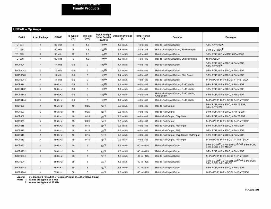
R – Op Amps
t # # per Package GBWP IQ Typical (μA)
VOS Max (mV)
Input Voltage Noise Density
(nV/rtHz)
Operating Voltage (V)
Temp. Range (°C) Features
4 1 90 kHz 6 1.5 125(1) 1.8 to 5.5 -40 to +85 Rail-to-Rail Input/Output
5 1 90 kHz 6 1.5 125(1) 1.8 to 5.5 -40 to +85 Rail-to-Rail Input/Output, Shutdo
9 2 90 kHz 12 1.5 125(1) 1.8 to 5.5 -40 to +85 Rail-to-Rail Input/Output
0 4 90 kHz 5 1.5 125(1) 1.8 to 5.5 -40 to +85 Rail-to-Rail Input/Output, Shutdo
041 1 14 kHz 0.6 3 170(1) 1.4 to 5.5 -40 to +85 Rail-to-Rail Input/Output
042 2 14 kHz 0.6 3 170(1) 1.4 to 5.5 -40 to +85 Rail-to-Rail Input/Output
043 1 14 kHz 0.6 3 170(1) 1.4 to 5.5 -40 to +85 Rail-to-Rail Input/Output, Chip S
044 4 14 kHz 0.6 3 170(1) 1.4 to 5.5 -40 to +85 Rail-to-Rail Input/Output
141 1 100 kHz 0.6 3 170(1) 1.4 to 5.5 -40 to +85 Rail-to-Rail Input/Output, G>10
142 2 100 kHz 0.6 3 170(1) 1.4 to 5.5 -40 to +85 Rail-to-Rail Input/Output, G>10
143 1 100 kHz 0.6 3 170(1) 1.4 to 5.5 -40 to +85 Rail-to-Rail Input/Output, G>10 Chip Select
144 4 100 kHz 0.6 3 170(1) 1.4 to 5.5 -40 to +85 Rail-to-Rail Input/Output, G>10
06 1 155 kHz 19 0.25 38(1) 2.5 to 5.5 -40 to +85 Rail-to-Rail Output
07 2 155 kHz 19 0.25 38(1) 2.5 to 5.5 -40 to +85 Rail-to-Rail Output
08 1 155 kHz 19 0.25 38(1) 2.5 to 5.5 -40 to +85 Rail-to-Rail Output, Chip Select
09 4 155 kHz 19 0.25 38(1) 2.5 to 5.5 -40 to +85 Rail-to-Rail Output
16 1 190 kHz 19 0.15 32(1) 2.3 to 5.5 -40 to +85 Rail-to-Rail Output, PNP Input
17 2 190 kHz 19 0.15 32(1) 2.3 to 5.5 -40 to +85 Rail-to-Rail Output, PNP
18 1 190 kHz 19 0.15 32(1) 2.3 to 5.5 -40 to +85 Rail-to-Rail Output, Chip Select,
19 4 190 kHz 19 0.15 32(1) 2.3 to 5.5 -40 to +85 Rail-to-Rail Output, PNP Input
231 1 300 kHz 20 5 52(1) 1.8 to 5.5 -40 to +125 Rail-to-Rail Input/Output
232 2 300 kHz 20 5 52(1) 1.8 to 5.5 -40 to +125 Rail-to-Rail Input/Output
234 4 300 kHz 20 5 52(1) 1.8 to 5.5 -40 to +125 Rail-to-Rail Input/Output
241 1 550 kHz 50 5 45(1) 1.8 to 5.5 -40 to +125 Rail-to-Rail Input/Output
242 2 550 kHz 50 5 45(1) 1.8 to 5.5 -40 to +125 Rail-to-Rail Input/Output
244 4 550 kHz 50 5 45(1) 1.8 to 5.5 -40 to +125 Rail-to-Rail Input/Output
nd: S = Standard Pinout; R = Reverse Pinout; U = Alternative Pinout1: Values are typical at 1 kHz2: Values are typical at 10 kHz

PAGE 21
MCP6 5-Pin SOT-23(U), 5-Pin SC-70(S,R,U)
MCP6 8-Pin PDIP, 8-Pin SOIC, 8-Pin MSOP
MCP6 14-Pin PDIP, 14-Pin SOIC, 14-Pin TSSOP
MCP6 5-Pin SOT-23(S,R), 8-Pin PDIP, 8-Pin SOIC, 8-Pin MSOP
MCP6 8-Pin PDIP, 8-Pin SOIC, 8-Pin MSOP
MCP6 elect 5-Pin SOT-23(S), 8-Pin PDIP, 8-Pin SOIC, 8-Pin MSOP
MCP6 14-Pin PDIP, 14-Pin SOIC, 14-Pin TSSOP
MCP6 onnected, 8-Pin PDIP, 8-Pin SOIC, 8-Pin MSOP
MCP6 5-Pin SOT-23(S,R),8-Pin PDIP, 8-Pin SOIC, 8-Pin TSSOP,
MCP6 8-Pin PDIP, 8-Pin SOIC, 8-Pin TSSOP
MCP6 6-Pin SOT-23(S), 8-Pin PDIP, 8-Pin SOIC, 8-Pin TSSOP
MCP6 14-Pin PDIP, 14-Pin SOIC, 14-Pin TSSOP
MCP6 5-Pin SOT-23(S,R), 8-Pin PDIP, 8-Pin SOIC, 8-Pin MSOP
MCP6 8-Pin PDIP, 8-Pin SOIC, 8-Pin MSOP
MCP6 elect 6-Pin SOT-23(S,R), 8-Pin PDIP, 8-Pin SOIC, 8-Pin MSOP
MCP6 14-Pin PDIP, 14-Pin SOIC, 14-Pin TSSOP
MCP6 onnected, 8-Pin PDIP, 8-Pin SOIC, 8-Pin MSOP
MCP6 5-Pin SOT-23(S,R), 8-Pin PDIP, 8-Pin SOIC, 8-Pin MSOP
MCP6 8-Pin PDIP, 8-Pin SOIC, 8-Pin MSOP
MCP6 elect 6-Pin SOT-23(S), 8-Pin PDIP, 8-Pin SOIC, 8-Pin MSOP
MCP6 14-Pin PDIP, 14-Pin SOIC, 14-Pin TSSOP
MCP6 onnected, 8-Pin PDIP, 8-Pin SOIC, 8-Pin MSOP
MCP6 C VREF 8-Pin PDIP, 8-Pin SOIC, 8-Pin TSSOP
LINEA
Pa Packages
LegeNOT
Analog/InterfaceFamily Products
001 1 1 MHz 140 4.5 28(1) 1.8 to 5.5 -40 to +125 Rail-to-Rail Input/Output
002 2 1 MHz 140 4.5 28(1) 1.8 to 5.5 -40 to +125 Rail-to-Rail Input/Output
004 4 1 MHz 140 4.5 28(1) 1.8 to 5.5 -40 to +125 Rail-to-Rail Input/Output
271 1 2 MHz 170 3 20(1) 2.0 to 5.5 -40 to +125 Rail-to-Rail Input/Output
272 2 2 MHz 170 3 20(1) 2.0 to 5.5 -40 to +125 Rail-to-Rail Input/Output
273 1 2 MHz 170 3 20(1) 2.0 to 5.5 -40 to +125 Rail-to-Rail Input/Output, Chip S
274 4 2 MHz 170 3 20(1) 2.0 to 5.5 -40 to +125 Rail-to-Rail Input/Output
275 2 2 MHz 150 3 20(1) 2.0 to 5.5 -40 to +125 Rail-to-Rail Input/Output, Dual cChip Select
01 1 2.8 MHz 230 2 29(1) 2.7 to 5.5 -40 to +125 Rail-to-Rail Output
02 2 2.8 MHz 230 2 29(1) 2.7 to 5.5 -40 to +125 Rail-to-Rail Output
03 1 2.8 MHz 230 2 29(1) 2.7 to 5.5 -40 to +125 Rail-to-Rail Output, Chip Select
04 4 2.8 MHz 230 2 29(1) 2.7 to 5.5 -40 to +125 Rail-to-Rail Output
281 1 5 MHz 445 3 16(1) 2.2 to 5.5 -40 to +125 Rail-to-Rail Input/Output
282 2 5 MHz 445 3 16(1) 2.2 to 5.5 -40 to +125 Rail-to-Rail Input/Output
283 1 5 MHz 445 3 16(1) 2.2 to 5.5 -40 to +125 Rail-to-Rail Input/Output, Chip S
284 4 5 MHz 445 3 16(1) 2.2 to 5.5 -40 to +125 Rail-to-Rail Input/Output
285 2 5 MHz 400 3 16(1) 2.2 to 5.5 -40 to +125 Rail-to-Rail Input/Output, Dual cChip Select
291 1 10 MHz 1000 3 8.7(2) 2.4 to 5.5 -40 to +125 Rail-to-Rail Input/Output
292 2 10 MHz 1000 3 8.7(2) 2.4 to 5.5 -40 to +125 Rail-to-Rail Input/Output
293 1 10 MHz 1000 3 8.7(2) 2.4 to 5.5 -40 to +125 Rail-to-Rail Input/Output, Chip S
294 4 10 MHz 1000 3 8.7(2) 2.4 to 5.5 -40 to +125 Rail-to-Rail Input/Output
295 2 10 MHz 1100 3 8.7(2) 2.4 to 5.5 -40 to +125 Rail-to-Rail Input/Output, Dual cChip Select
021 1 10 MHz 1000 0.5 8.7(2) 2.5 to 5.5 -40 to +125 Rail-to-Rail Input/Output, 1/2 VC
R – Op Amps (continued)
rt # # per Package GBWP IQ Typical (μA)
VOS Max (mV)
Input Voltage Noise Density
(nV/rtHz)
Operating Voltage (V)
Temp. Range (°C) Features
nd: S = Standard Pinout; R = Reverse Pinout; U = Alternative PinoutE 1: Values are typical at 1 kHz
2: Values are typical at 10 kHz
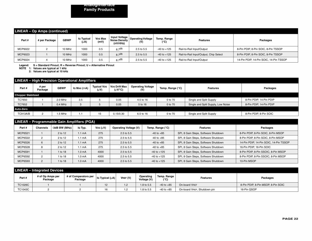
PAGE 22
Analog/Interface
MCP6 8-Pin PDIP, 8-Pin SOIC, 8-Pin TSSOP
MCP6 elect 8-Pin PDIP, 8-Pin SOIC, 8-Pin TSSOP
MCP6 14-Pin PDIP, 14-Pin SOIC, 14-Pin TSSOP
LINEA
Part s Packages
Chopper
TC765 8-Pin PDIP, 14-Pin PDIP
TC765 Low Noise 8-Pin PDIP, 14-Pin PDIP
Auto-Ze
TC913 8-Pin PDIP, 8-Pin SOIC
LINEA
Part Packages
MCP6 tdown 8-Pin PDIP, 8-Pin SOIC, 8-Pin MSOP
MCP6 tdown 8-Pin PDIP, 8-Pin SOIC, 8-Pin MSOP
MCP6 tdown 14-Pin PDIP, 14-Pin SOIC, 14-Pin TSSOP
MCP6 tdown 16-Pin PDIP, 16-Pin SOIC
MCP6 tdown 8-Pin PDIP, 8-Pin SSOIC, 8-Pin MSOP
MCP6 tdown 8-Pin PDIP, 8-Pin SSOIC, 8-Pin MSOP
MCP6 tdown 10-Pin MSOP
LINEA
Part Packages
TC102 8-Pin PDIP, 8-Pin MSOP, 8-Pin SOIC
TC104 16-Pin QSOP
LINEA
Par Packages
LegeNOTE
Family Products
022 2 10 MHz 1000 0.5 8.7(2) 2.5 to 5.5 -40 to +125 Rail-to-Rail Input/Output
023 1 10 MHz 1000 0.5 8.7(2) 2.5 to 5.5 -40 to +125 Rail-to-Rail Input/Output, Chip S
024 4 10 MHz 1000 0.5 8.7(2) 2.5 to 5.5 -40 to +125 Rail-to-Rail Input/Output
R – High Precision Operational Amplifiers
# # per Package GBWP IQ MAX (mA) Typical VOS
(μV)VOS Drift Max
(μV/°C)Operating Voltage
(V) Temp. Range (°C) Feature
Stabilized
0 1 2.0 MHz 3.5 5 0.05 4.5 to 16 0 to 70 Single and Split Supply
2 1 0.4 MHz 3 5 0.05 5 to 16 0 to 70 Single and Split Supply,
ro
A/B 2 1.5 MHz 1.1 15 0.15/0.30 6.5 to 16 0 to 70 Single and Split Supply
R – Programmable Gain Amplifiers (PGA)
# Channels -3dB BW (MHz) IQ Typ. VOS (μV) Operating Voltage (V) Temp. Range (°C) Features
S21 1 2 to 12 1.1 mA 275 2.5 to 5.5 -40 to +85 SPI, 8 Gain Steps, Software Shu
S22 2 2 to 12 1.1 mA 275 2.5 to 5.5 -40 to +85 SPI, 8 Gain Steps, Software Shu
S26 6 2 to 12 1.1 mA 275 2.5 to 5.5 -40 to +85 SPI, 8 Gain Steps, Software Shu
S28 8 2 to 12 1.1 mA 275 2.5 to 5.5 -40 to +85 SPI, 8 Gain Steps, Software Shu
S91 1 1 to 18 1.0 mA 4000 2.5 to 5.5 -40 to +125 SPI, 8 Gain Steps, Software Shu
S92 2 1 to 18 1.0 mA 4000 2.5 to 5.5 -40 to +125 SPI, 8 Gain Steps, Software Shu
S93 2 1 to 18 1.0 mA 4000 2.5 to 5.5 -40 to +125 SPI, 8 Gain Steps, Software Shu
R – Integrated Devices
# # of Op Amps per Package
# of Comparators per Package IQ Typical (μA) VREF (V) Operating
Voltage (V)Temp. Range
(°C) Features
6C 1 1 12 1.2 1.8 to 5.5 -40 to +85 On-board VREF
3C 2 2 16 1.2 1.8 to 5.5 -40 to +85 On-board VREF, Shutdown pin
R – Op Amps (continued)
t # # per Package GBWP IQ Typical (μA)
VOS Max (mV)
Input Voltage Noise Density
(nV/rtHz)
Operating Voltage (V)
Temp. Range (°C) Features
nd: S = Standard Pinout; R = Reverse Pinout; U = Alternative Pinout1: Values are typical at 1 kHz2: Values are typical at 10 kHz
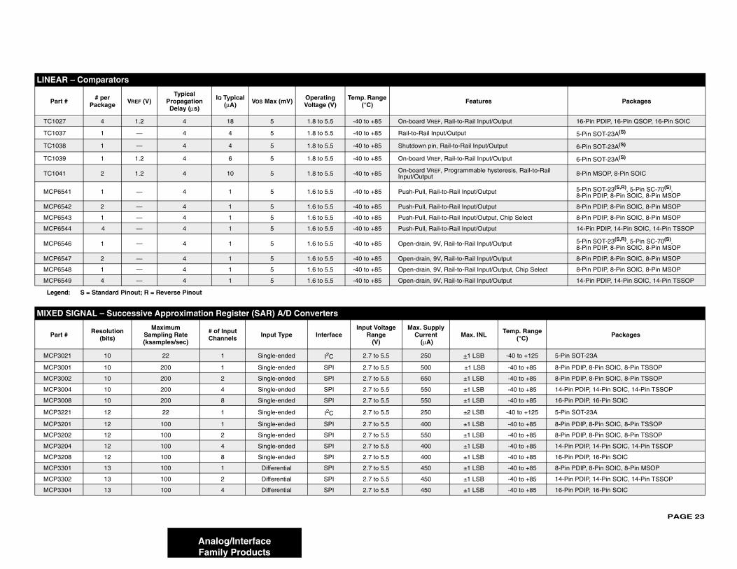
PAGE 23
LINEA
Par Packages
TC10 16-Pin PDIP, 16-Pin QSOP, 16-Pin SOIC
TC10 5-Pin SOT-23A(S)
TC10 6-Pin SOT-23A(S)
TC10 6-Pin SOT-23A(S)
TC10 Rail-to-Rail 8-Pin MSOP, 8-Pin SOIC
MCP6 5-Pin SOT-23(S,R), 5-Pin SC-70(S), 8-Pin PDIP, 8-Pin SOIC, 8-Pin MSOP
MCP6 8-Pin PDIP, 8-Pin SOIC, 8-Pin MSOP
MCP6 elect 8-Pin PDIP, 8-Pin SOIC, 8-Pin MSOP
MCP6 14-Pin PDIP, 14-Pin SOIC, 14-Pin TSSOP
MCP6 5-Pin SOT-23(S,R), 5-Pin SC-70(S), 8-Pin PDIP, 8-Pin SOIC, 8-Pin MSOP
MCP6 8-Pin PDIP, 8-Pin SOIC, 8-Pin MSOP
MCP6 hip Select 8-Pin PDIP, 8-Pin SOIC, 8-Pin MSOP
MCP6 14-Pin PDIP, 14-Pin SOIC, 14-Pin TSSOP
Lege
MIXED
Par . Range °C) Packages
MCP3 to +125 5-Pin SOT-23A
MCP3 to +85 8-Pin PDIP, 8-Pin SOIC, 8-Pin TSSOP
MCP3 to +85 8-Pin PDIP, 8-Pin SOIC, 8-Pin TSSOP
MCP3 to +85 14-Pin PDIP, 14-Pin SOIC, 14-Pin TSSOP
MCP3 to +85 16-Pin PDIP, 16-Pin SOIC
MCP3 to +125 5-Pin SOT-23A
MCP3 to +85 8-Pin PDIP, 8-Pin SOIC, 8-Pin TSSOP
MCP3 to +85 8-Pin PDIP, 8-Pin SOIC, 8-Pin TSSOP
MCP3 to +85 14-Pin PDIP, 14-Pin SOIC, 14-Pin TSSOP
MCP3 to +85 16-Pin PDIP, 16-Pin SOIC
MCP3 to +85 8-Pin PDIP, 8-Pin SOIC, 8-Pin MSOP
MCP3 to +85 14-Pin PDIP, 14-Pin SOIC, 14-Pin TSSOP
MCP3 to +85 16-Pin PDIP, 16-Pin SOIC
Analog/InterfaceFamily Products
R – Comparators
t # # per Package VREF (V)
TypicalPropagation Delay (μs)
IQ Typical (μA) VOS Max (mV) Operating
Voltage (V)Temp. Range
(°C) Features
27 4 1.2 4 18 5 1.8 to 5.5 -40 to +85 On-board VREF, Rail-to-Rail Input/Output
37 1 — 4 4 5 1.8 to 5.5 -40 to +85 Rail-to-Rail Input/Output
38 1 — 4 4 5 1.8 to 5.5 -40 to +85 Shutdown pin, Rail-to-Rail Input/Output
39 1 1.2 4 6 5 1.8 to 5.5 -40 to +85 On-board VREF, Rail-to-Rail Input/Output
41 2 1.2 4 10 5 1.8 to 5.5 -40 to +85 On-board VREF, Programmable hysteresis,Input/Output
541 1 — 4 1 5 1.6 to 5.5 -40 to +85 Push-Pull, Rail-to-Rail Input/Output
542 2 — 4 1 5 1.6 to 5.5 -40 to +85 Push-Pull, Rail-to-Rail Input/Output
543 1 — 4 1 5 1.6 to 5.5 -40 to +85 Push-Pull, Rail-to-Rail Input/Output, Chip S
544 4 — 4 1 5 1.6 to 5.5 -40 to +85 Push-Pull, Rail-to-Rail Input/Output
546 1 — 4 1 5 1.6 to 5.5 -40 to +85 Open-drain, 9V, Rail-to-Rail Input/Output
547 2 — 4 1 5 1.6 to 5.5 -40 to +85 Open-drain, 9V, Rail-to-Rail Input/Output
548 1 — 4 1 5 1.6 to 5.5 -40 to +85 Open-drain, 9V, Rail-to-Rail Input/Output, C
549 4 — 4 1 5 1.6 to 5.5 -40 to +85 Open-drain, 9V, Rail-to-Rail Input/Output
nd: S = Standard Pinout; R = Reverse Pinout
SIGNAL – Successive Approximation Register (SAR) A/D Converters
t # Resolution (bits)
MaximumSampling Rate (ksamples/sec)
# of Input Channels Input Type Interface
Input Voltage Range
(V)
Max. Supply Current
(μA)Max. INL Temp
(
021 10 22 1 Single-ended I2C 2.7 to 5.5 250 +1 LSB -40
001 10 200 1 Single-ended SPI 2.7 to 5.5 500 ±1 LSB -40
002 10 200 2 Single-ended SPI 2.7 to 5.5 650 ±1 LSB -40
004 10 200 4 Single-ended SPI 2.7 to 5.5 550 ±1 LSB -40
008 10 200 8 Single-ended SPI 2.7 to 5.5 550 ±1 LSB -40
221 12 22 1 Single-ended I2C 2.7 to 5.5 250 ±2 LSB -40
201 12 100 1 Single-ended SPI 2.7 to 5.5 400 ±1 LSB -40
202 12 100 2 Single-ended SPI 2.7 to 5.5 550 ±1 LSB -40
204 12 100 4 Single-ended SPI 2.7 to 5.5 400 ±1 LSB -40
208 12 100 8 Single-ended SPI 2.7 to 5.5 400 ±1 LSB -40
301 13 100 1 Differential SPI 2.7 to 5.5 450 ±1 LSB -40
302 13 100 2 Differential SPI 2.7 to 5.5 450 ±1 LSB -40
304 13 100 4 Differential SPI 2.7 to 5.5 450 ±1 LSB -40
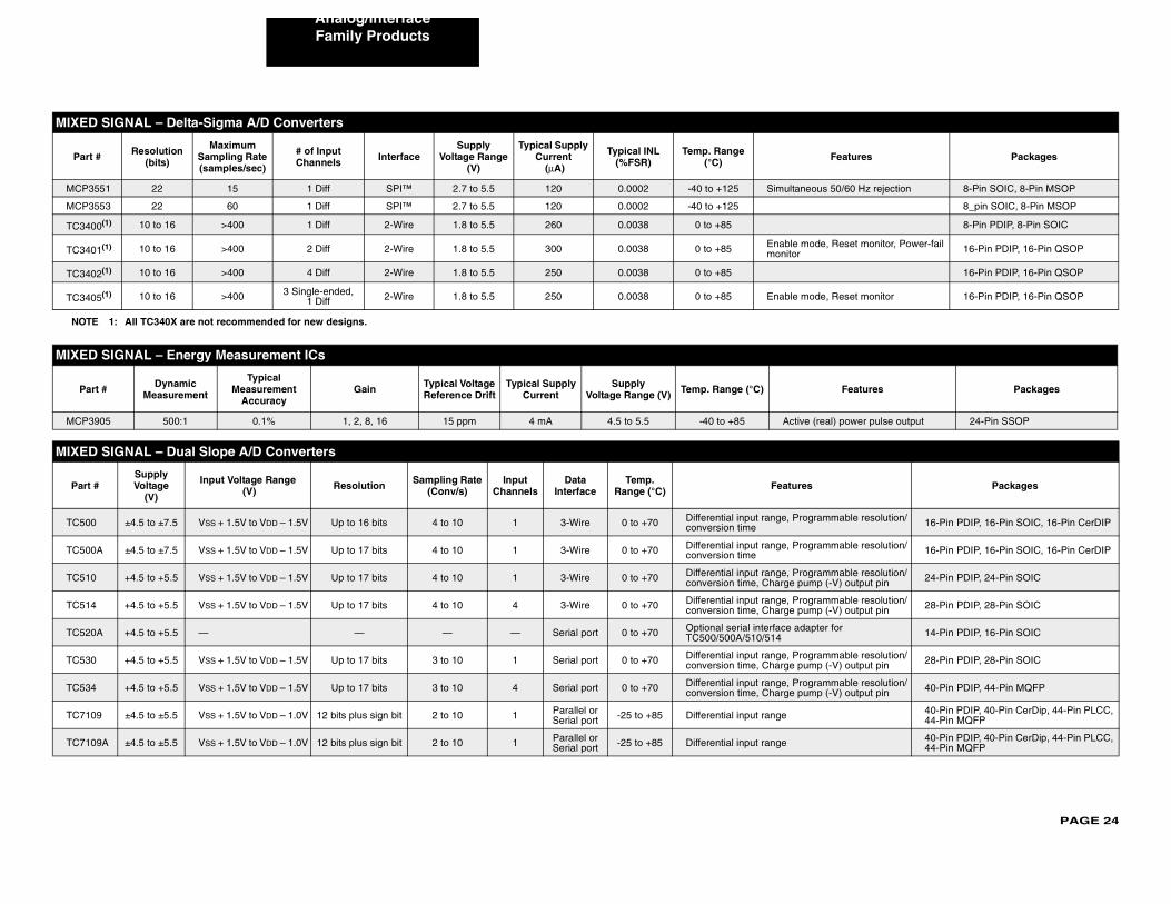
PAGE 24
Analog/Interface
MIXED
Part Features Packages
MCP3 us 50/60 Hz rejection 8-Pin SOIC, 8-Pin MSOP
MCP3 8_pin SOIC, 8-Pin MSOP
TC340 8-Pin PDIP, 8-Pin SOIC
TC340de, Reset monitor, Power-fail 16-Pin PDIP, 16-Pin QSOP
TC340 16-Pin PDIP, 16-Pin QSOP
TC340 de, Reset monitor 16-Pin PDIP, 16-Pin QSOP
NOTE
MIXED
Par Features Packages
MCP3 (real) power pulse output 24-Pin SSOP
MIXED
Part Packages
TC500 rammable resolution/ 16-Pin PDIP, 16-Pin SOIC, 16-Pin CerDIP
TC500 rammable resolution/ 16-Pin PDIP, 16-Pin SOIC, 16-Pin CerDIP
TC510 rammable resolution/p (-V) output pin 24-Pin PDIP, 24-Pin SOIC
TC514 rammable resolution/p (-V) output pin 28-Pin PDIP, 28-Pin SOIC
TC520 ter for 14-Pin PDIP, 16-Pin SOIC
TC530 rammable resolution/p (-V) output pin 28-Pin PDIP, 28-Pin SOIC
TC534 rammable resolution/p (-V) output pin 40-Pin PDIP, 44-Pin MQFP
TC710 40-Pin PDIP, 40-Pin CerDip, 44-Pin PLCC, 44-Pin MQFP
TC710 40-Pin PDIP, 40-Pin CerDip, 44-Pin PLCC, 44-Pin MQFP
Family Products
SIGNAL – Delta-Sigma A/D Converters
# Resolution (bits)
MaximumSampling Rate (samples/sec)
# of Input Channels Interface
Supply Voltage Range
(V)
Typical Supply Current
(μA)
Typical INL (%FSR)
Temp. Range (°C)
551 22 15 1 Diff SPI™ 2.7 to 5.5 120 0.0002 -40 to +125 Simultaneo
553 22 60 1 Diff SPI™ 2.7 to 5.5 120 0.0002 -40 to +125
0(1) 10 to 16 >400 1 Diff 2-Wire 1.8 to 5.5 260 0.0038 0 to +85
1(1) 10 to 16 >400 2 Diff 2-Wire 1.8 to 5.5 300 0.0038 0 to +85 Enable momonitor
2(1) 10 to 16 >400 4 Diff 2-Wire 1.8 to 5.5 250 0.0038 0 to +85
5(1) 10 to 16 >400 3 Single-ended,1 Diff 2-Wire 1.8 to 5.5 250 0.0038 0 to +85 Enable mo
1: All TC340X are not recommended for new designs.
SIGNAL – Energy Measurement ICs
t # Dynamic Measurement
Typical Measurement
AccuracyGain Typical Voltage
Reference DriftTypical Supply
CurrentSupply
Voltage Range (V) Temp. Range (°C)
905 500:1 0.1% 1, 2, 8, 16 15 ppm 4 mA 4.5 to 5.5 -40 to +85 Active
SIGNAL – Dual Slope A/D Converters
#Supply Voltage
(V)
Input Voltage Range (V) Resolution Sampling Rate
(Conv/s)Input
ChannelsData
InterfaceTemp.
Range (°C) Features
±4.5 to ±7.5 VSS + 1.5V to VDD – 1.5V Up to 16 bits 4 to 10 1 3-Wire 0 to +70 Differential input range, Progconversion time
A ±4.5 to ±7.5 VSS + 1.5V to VDD – 1.5V Up to 17 bits 4 to 10 1 3-Wire 0 to +70 Differential input range, Progconversion time
+4.5 to +5.5 VSS + 1.5V to VDD – 1.5V Up to 17 bits 4 to 10 1 3-Wire 0 to +70 Differential input range, Progconversion time, Charge pum
+4.5 to +5.5 VSS + 1.5V to VDD – 1.5V Up to 17 bits 4 to 10 4 3-Wire 0 to +70 Differential input range, Progconversion time, Charge pum
A +4.5 to +5.5 — — — — Serial port 0 to +70 Optional serial interface adapTC500/500A/510/514
+4.5 to +5.5 VSS + 1.5V to VDD – 1.5V Up to 17 bits 3 to 10 1 Serial port 0 to +70 Differential input range, Progconversion time, Charge pum
+4.5 to +5.5 VSS + 1.5V to VDD – 1.5V Up to 17 bits 3 to 10 4 Serial port 0 to +70 Differential input range, Progconversion time, Charge pum
9 ±4.5 to ±5.5 VSS + 1.5V to VDD – 1.0V 12 bits plus sign bit 2 to 10 1 Parallel or Serial port -25 to +85 Differential input range
9A ±4.5 to ±5.5 VSS + 1.5V to VDD – 1.0V 12 bits plus sign bit 2 to 10 1 Parallel or Serial port -25 to +85 Differential input range
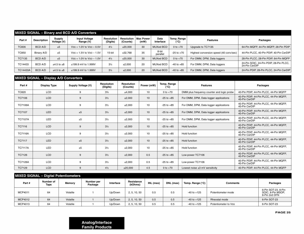
PAGE 25
MIXED
Part tures Packages
TC83 5 64-Pin MQFP, 44-Pin MQFP, 28-Pin PDIP
TC85 n speed (40 conv/sec) 44-Pin PLCC, 40-Pin PDIP, 40-Pin CerDIP
TC71 ata loggers 28-Pin PLCC, 28-Pin PDIP, 64-Pin MQFP
TC14 ata loggers 24-Pin SOIC, 24-Pin PDIP, 28-Pin PLCC, 24-Pin CerDIP
TC14 ata loggers 24-Pin PDIP, 28-Pin PLCC, 24-Pin CerDIP
MIXED
Part Packages
TC82 ter and logic probe 40-Pin PDIP, 44-Pin PLCC, 44-Pin MQFP
TC71 ger applications 40-Pin PDIP, 44-Pin PLCC, 44-Pin MQFP, 40-Pin CerDIP
TC71 ger applications 40-Pin PDIP, 44-Pin PLCC, 44-Pin MQFP, 40-Pin CerDIP
TC71 ger applications 40-Pin PDIP, 44-Pin PLCC, 44-Pin MQFP, 40-Pin CerDIP
TC71 ger applications 40-Pin PDIP, 44-Pin PLCC, 44-Pin MQFP, 40-Pin CerDIP
TC711 40-Pin PDIP, 44-Pin PLCC, 44-Pin MQFP, 40-Pin CerDIP
TC711 40-Pin PDIP, 44-Pin PLCC, 44-Pin MQFP, 40-Pin CerDIP
TC711 40-Pin PDIP, 44-Pin PLCC, 44-Pin MQFP, 40-Pin CerDIP
TC711 40-Pin PDIP, 44-Pin PLCC, 44-Pin MQFP, 40-Pin CerDIP
TC71 40-Pin PDIP, 44-Pin PLCC, 44-Pin MQFP, 40-Pin CerDIP
TC71 40-Pin PDIP, 44-Pin PLCC, 44-Pin MQFP, 40-Pin CerDIP
TC71 itivity 40-Pin PDIP, 44-Pin PLCC, 44-Pin MQFP
MIXED
P Comments Packages
MCP4 otentiometer mode6-Pin SOT-23, 8-Pin SOIC, 8-Pin MSOP, 8-Pin 2x3 DFN
MCP4 heostat mode 6-Pin SOT-23
MCP4 otentiometer to VSS 6-Pin SOT-23
Analog/InterfaceFamily Products
SIGNAL – Binary and BCD A/D Converters
# Description Supply Voltage (V)
Input Voltage Range (V)
Resolution(Digits)
Resolution(Counts)
Max Power(mW)
Data Interface
Temp. Range (°C) Fea
5 BCD A/D ±5 VSS + 1.0V to VDD – 0.5V 4½ ±20,000 30 MUXed BCD 0 to +70 Upgrade to TC713
0 Binary A/D ±5 VSS + 1.5V to VDD – 1.5V 15-bit ±32,768 35 8-bit parallel -25 to +70 Highest conversio
35 BCD A/D ±5 VSS + 1.0V to VDD – 1.0V 4½ ±20,000 30 MUXed BCD 0 to +70 For DMM, DPM, D
433 BCD A/D ±4.5 to ±8 ±199.9 mV to 1.999V 3½ ±2,000 20 MUXed BCD -40 to +85 For DMM, DPM, D
433A BCD A/D ±4.5 to ±8 ±199.9 mV to 1.999V 3½ ±2,000 20 MUXed BCD -40 to +85 For DMM, DPM, D
SIGNAL – Display A/D Converters
# Display Type Supply Voltage (V) Resolution (Digits)
Resolution (Counts) Power (mW) Temp. Range
(°C) Features
0 LCD 9 3¾ ±4,000 10 0 to +70 DMM plus frequency coun
06 LCD 9 3½ ±2,000 10 -25 to +85 For DMM, DPM, Data log
06A LCD 9 3½ ±2,000 10 -25 to +85 For DMM, DPM, Data log
07 LED ±5 3½ ±2,000 10 -25 to +85 For DMM, DPM, Data log
07A LED ±5 3½ ±2,000 10 -25 to +85 For DMM, DPM, Data log
6 LCD 9 3½ ±2,000 10 -25 to +85 Hold function
6A LCD 9 3½ ±2,000 10 -25 to +85 Hold function
7 LED ±5 3½ ±2,000 10 -25 to +85 Hold function
7A LED ±5 3½ ±2,000 10 -25 to +85 Hold function
26 LCD 9 3½ ±2,000 0.5 -25 to +85 Low-power TC7106
26A LCD 9 3½ ±2,000 0.5 -25 to +85 Low-power TC7106
29 LCD 9 4½ ±20,000 4.5 0 to +70 Lowest noise ±3 mV sens
SIGNAL – Digital Potentiometers
art # Number of Taps Memory Number per
Package Interface Resistance (kOhms) INL (max) DNL (max) Temp. Range (°C)
011 64 Volatile 1 Up/Down 2, 5, 10, 50 0.5 0.5 -40 to +125 P
012 64 Volatile 1 Up/Down 2, 5, 10, 50 0.5 0.5 -40 to +125 R
013 64 Volatile 1 Up/Down 2, 5, 10, 50 0.5 0.5 -40 to +125 P
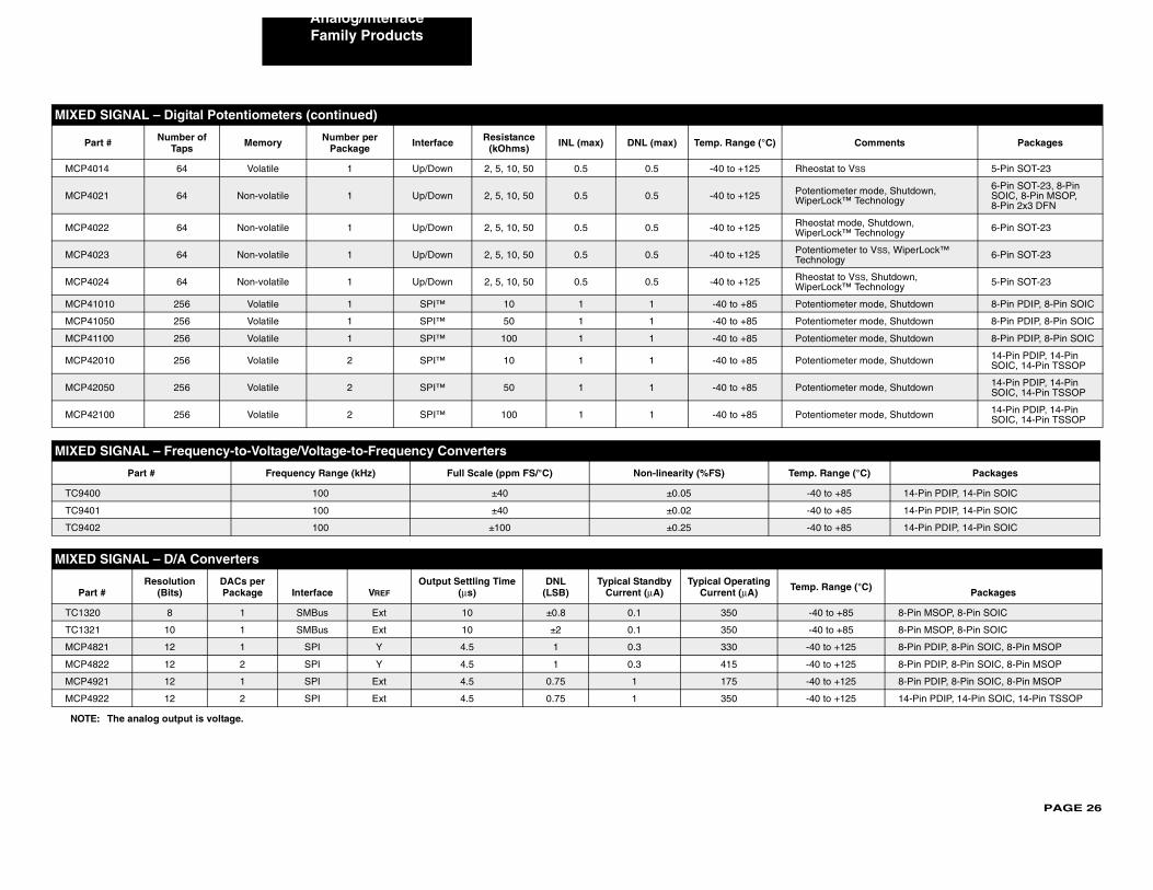
PAGE 26
Analog/Interface
MCP4 heostat to VSS 5-Pin SOT-23
MCP4 otentiometer mode, Shutdown, iperLock™ Technology
6-Pin SOT-23, 8-Pin SOIC, 8-Pin MSOP, 8-Pin 2x3 DFN
MCP4 heostat mode, Shutdown, iperLock™ Technology 6-Pin SOT-23
MCP4 otentiometer to VSS, WiperLock™ echnology 6-Pin SOT-23
MCP4 heostat to VSS, Shutdown, iperLock™ Technology 5-Pin SOT-23
MCP4 otentiometer mode, Shutdown 8-Pin PDIP, 8-Pin SOIC
MCP4 otentiometer mode, Shutdown 8-Pin PDIP, 8-Pin SOIC
MCP4 otentiometer mode, Shutdown 8-Pin PDIP, 8-Pin SOIC
MCP4 otentiometer mode, Shutdown 14-Pin PDIP, 14-Pin SOIC, 14-Pin TSSOP
MCP4 otentiometer mode, Shutdown 14-Pin PDIP, 14-Pin SOIC, 14-Pin TSSOP
MCP4 otentiometer mode, Shutdown 14-Pin PDIP, 14-Pin SOIC, 14-Pin TSSOP
MIXED
p. Range (°C) Packages
TC940 -40 to +85 14-Pin PDIP, 14-Pin SOIC
TC940 -40 to +85 14-Pin PDIP, 14-Pin SOIC
TC940 -40 to +85 14-Pin PDIP, 14-Pin SOIC
MIXED
Par mp. Range (°C) Packages
TC132 -40 to +85 8-Pin MSOP, 8-Pin SOIC
TC132 -40 to +85 8-Pin MSOP, 8-Pin SOIC
MCP4 -40 to +125 8-Pin PDIP, 8-Pin SOIC, 8-Pin MSOP
MCP4 -40 to +125 8-Pin PDIP, 8-Pin SOIC, 8-Pin MSOP
MCP4 -40 to +125 8-Pin PDIP, 8-Pin SOIC, 8-Pin MSOP
MCP4 -40 to +125 14-Pin PDIP, 14-Pin SOIC, 14-Pin TSSOP
NOTE
MIXED
Pa Comments Packages
Family Products
014 64 Volatile 1 Up/Down 2, 5, 10, 50 0.5 0.5 -40 to +125 R
021 64 Non-volatile 1 Up/Down 2, 5, 10, 50 0.5 0.5 -40 to +125 PW
022 64 Non-volatile 1 Up/Down 2, 5, 10, 50 0.5 0.5 -40 to +125 RW
023 64 Non-volatile 1 Up/Down 2, 5, 10, 50 0.5 0.5 -40 to +125 PT
024 64 Non-volatile 1 Up/Down 2, 5, 10, 50 0.5 0.5 -40 to +125 RW
1010 256 Volatile 1 SPI™ 10 1 1 -40 to +85 P
1050 256 Volatile 1 SPI™ 50 1 1 -40 to +85 P
1100 256 Volatile 1 SPI™ 100 1 1 -40 to +85 P
2010 256 Volatile 2 SPI™ 10 1 1 -40 to +85 P
2050 256 Volatile 2 SPI™ 50 1 1 -40 to +85 P
2100 256 Volatile 2 SPI™ 100 1 1 -40 to +85 P
SIGNAL – Frequency-to-Voltage/Voltage-to-Frequency Converters
Part # Frequency Range (kHz) Full Scale (ppm FS/°C) Non-linearity (%FS) Tem
0 100 ±40 ±0.05
1 100 ±40 ±0.02
2 100 ±100 ±0.25
SIGNAL – D/A Converters
t #Resolution
(Bits)DACs per Package Interface VREF
Output Settling Time (μs)
DNL(LSB)
Typical Standby Current (μA)
Typical Operating Current (μA) Te
0 8 1 SMBus Ext 10 ±0.8 0.1 350
1 10 1 SMBus Ext 10 ±2 0.1 350
821 12 1 SPI Y 4.5 1 0.3 330
822 12 2 SPI Y 4.5 1 0.3 415
921 12 1 SPI Ext 4.5 0.75 1 175
922 12 2 SPI Ext 4.5 0.75 1 350
: The analog output is voltage.
SIGNAL – Digital Potentiometers (continued)
rt # Number of Taps Memory Number per
Package Interface Resistance (kOhms) INL (max) DNL (max) Temp. Range (°C)

PAGE 27
INTER
Pa Packages
MCP2 interface to uffers, HW and 18-Pin PDIP, 18-Pin SOIC, 20-Pin TSSOP
MCP2ith enhanced
t and data byte 18-Pin PDIP, 18-Pin SOIC, 20-Pin TSSOP
MCP2 figurable I/O, 14-Pin PDIP, 14-Pin SOIC
MCP2 figurable I/O, on 14-Pin PDIP, 14-Pin SOIC
MCP2 xpander, WM outputs 14-Pin PDIP, 14-Pin SOIC
MCP2xpander, WM outputs, 14-Pin PDIP, 14-Pin SOIC
MCP2s max. CAN bus try standard 8-Pin PDIP, 8-Pin SOIC
NOT
INTER
tures Packages
MCP2 coder with both baud rate selection 14-Pin PDIP, 14-Pin SOIC
MCP2 coder 8-Pin PDIP, 8-Pin SOIC
MCP2 l handler plus bit baud rate, Low-cost
18-Pin PDIP, 18-Pin SOIC, 20-Pin SSOP
MCP2l handler plus bit chip for DTE
able ID18-Pin PDIP, 18-Pin SOIC, 20-Pin SSOP
MCP2l handler plus bit chip for DCE
able ID18-Pin PDIP, 18-Pin SOIC, 20-Pin SSOP
NOT
INTER
Par Packages
ENC2 patible, detection 28-Pin SOIC, 28-Pin SSOP, 28-Pin 6x6 QFN
Analog/InterfaceFamily Products
FACE – Controller Area Network (CAN) Products
rt # Operating Voltage (V)
Temperature Range (°C) Tx Buffers Rx Buffers Filters Masks Interrupt
Output Unique Features
510(1) 2.7 to 5.5 -40 to +125 3 2 6 2 YesCAN 2.0B Active controller with SPIMCU, 3 transmit buffers, 2 receive bSW message triggers
515 2.7 to 5.5 -40 to +125 3 2 6 2 YesMCP2510 pin compatible upgrade wfeatures including higher throughpufiltering
5020 2.7 to 5.5 -40 to +125 3 2 2 1 N/A CAN 2.0B Active I/O Expander, Con2 PWM outputs
5025 2.7 to 5.5 -40 to +85 3 2 2 1 N/A CAN 2.0B Active I/O Expander, Con2 PWM outputs, One-wire CAN opti
5050 2.7 to 5.5 -40 to +125 3 2 2 1 N/A Mixed-Signal CAN 2.0B Active I/O EConfigurable I/O, 4 10-bit ADCs, 2 P
5055 2.7 to 5.5 -40 to +85 3 2 2 1 N/AMixed-Signal CAN 2.0B Active I/O EConfigurable I/O, 4 10-bit ADCs, 2 POne-wire CAN option
551 4.5 to 5.5 -40 to +125 n/a n/a n/a n/a N/AHigh-speed CAN Transceiver (1 Mbpspeed), ISO11898 compatible, Induspinout
E 1: Not recommended for new designs.
FACE – Infrared Products
Part # Operating Voltage (V) Operating Temperature Range (°C) Max. Baud Rate (Kbaud) Unique Fea
120 2.5 to 5.5 -40 to +85 325 UART to IR encoder/dehardware and software
122 1.8 to 5.5 -40 to +85 16x less than clock input UART to IR encoder/de
140 2.7 to 5.5 -40 to +85 9.6 IrDA® Standard protocoencoder/decoder, Fixed
150 3.0 to 5.5 -40 to +85 115.2IrDA® Standard protocoencoder/decoder on oneapplications, Programm
155 3.0 to 5.5 -40 to +85 115.2IrDA® Standard protocoencoder/decoder on oneapplications, Programm
E: IrDA® is a registered trademark of Infrared Data Association.
FACE – Ethernet Products
t # Operating Voltage (V)Operating
Temperature Range (°C)
MAC PHY TX/RX Dual Port RAM
Bus Type
Max Bus Speed (MHz)
Features
8J60 3.14 to 3.45 -40 to +85 yes 10-Base-T 8 KB SPI 25 Ethernet controller, IEEE 802.3 comLoopback Test modes, Auto-polarity
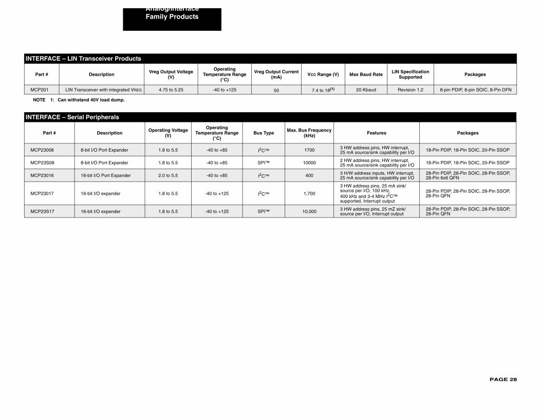
PAGE 28
Analog/Interface
INTER
Part ate LIN Specification Supported Packages
MCP2 Revision 1.2 8-pin PDIP, 8-pin SOIC, 8-Pin DFN
NOTE
INTER
P ures Packages
MCP2 s, HW interrupt, k capability per I/O 18-Pin PDIP, 18-Pin SOIC, 20-Pin SSOP
MCP2 s, HW interrupt, k capability per I/O 18-Pin PDIP, 18-Pin SOIC, 20-Pin SSOP
MCP2 puts, HW interrupt, k capability per I/O
28-Pin PDIP, 28-Pin SOIC, 28-Pin SSOP, 28-Pin 6x6 QFN
MCP2
s, 25 mA sink/0 kHz,
MHz I2C™ pt output
28-Pin PDIP, 28-Pin SOIC, 28-Pin SSOP, 28-Pin QFN
MCP2 s, 25 mZ sink/terrupt output
28-Pin PDIP, 28-Pin SOIC, 28-Pin SSOP, 28-Pin QFN
Family Products
FACE – LIN Transceiver Products
# Description Vreg Output Voltage (V)
Operating Temperature Range
(°C)
Vreg Output Current (mA) VCC Range (V) Max Baud R
01 LIN Transceiver with integrated VREG 4.75 to 5.25 -40 to +125 50 7.4 to 18(1) 20 Kbaud
1: Can withstand 40V load dump.
FACE – Serial Peripherals
art # Description Operating Voltage (V)
Operating Temperature Range
(°C)Bus Type Max. Bus Frequency
(kHz) Feat
3008 8-bit I/O Port Expander 1.8 to 5.5 -40 to +85 I2C™ 1700 3 HW address pin25 mA source/sin
3S08 8-bit I/O Port Expander 1.8 to 5.5 -40 to +85 SPI™ 10000 2 HW address pin25 mA source/sin
3016 16-bit I/O Port Expander 2.0 to 5.5 -40 to +85 I2C™ 400 3 H/W address in25 mA source/sin
3017 16-bit I/O expander 1.8 to 5.5 -40 to +125 I2C™ 1,700
3 HW address pinsource per I/O, 10400 kHz and 3-4 supported, Interru
3S17 16-bit I/O expander 1.8 to 5.5 -40 to +125 SPI™ 10,000 3 HW address pinsource per I/O, In
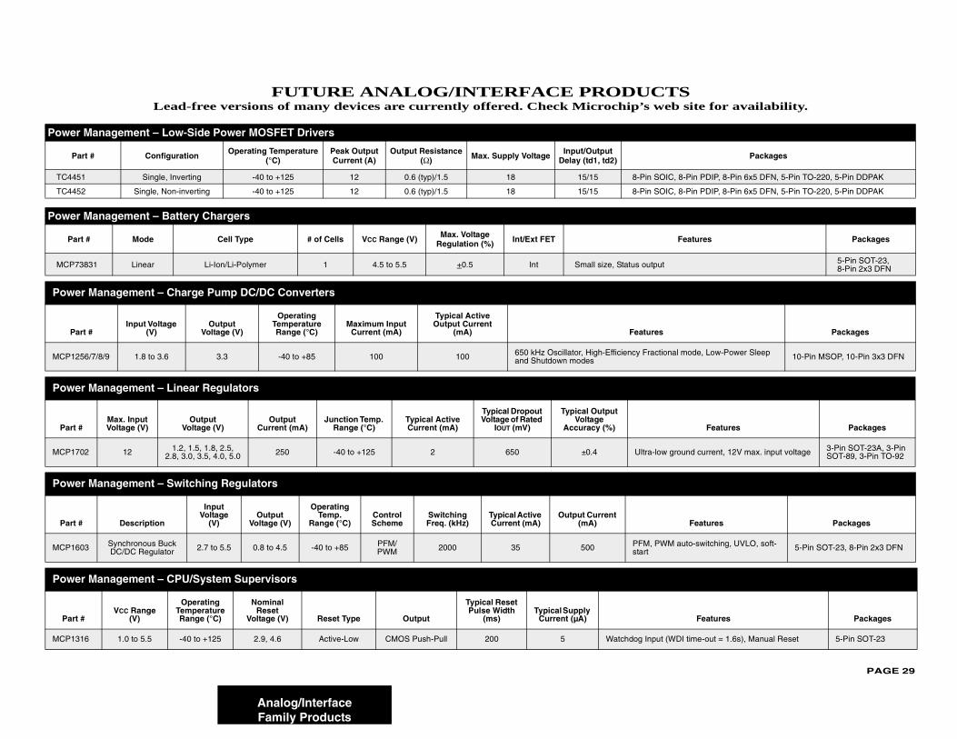
PAGE 29
TSeb site for availability.
Power
P Packages
TC44 IC, 8-Pin PDIP, 8-Pin 6x5 DFN, 5-Pin TO-220, 5-Pin DDPAK
TC44 IC, 8-Pin PDIP, 8-Pin 6x5 DFN, 5-Pin TO-220, 5-Pin DDPAK
Power
Pa Features Packages
MCP7 5-Pin SOT-23, 8-Pin 2x3 DFN
Powe
Pa Packages
MCP12 nal mode, Low-Power Sleep 10-Pin MSOP, 10-Pin 3x3 DFN
Powe
Part Features Packages
MCP17 ground current, 12V max. input voltage 3-Pin SOT-23A, 3-Pin SOT-89, 3-Pin TO-92
Powe
Part Features Packages
MCP16 M auto-switching, UVLO, soft- 5-Pin SOT-23, 8-Pin 2x3 DFN
Powe
Part Features Packages
MCP13 (WDI time-out = 1.6s), Manual Reset 5-Pin SOT-23
Analog/InterfaceFamily Products
FUTURE ANALOG/INTERFACE PRODUCLead-free versions of many devices are currently offered. Check Microchip’s w
Management – Low-Side Power MOSFET Drivers
art # Configuration Operating Temperature (°C)
Peak Output Current (A)
Output Resistance (Ω) Max. Supply Voltage Input/Output
Delay (td1, td2)
51 Single, Inverting -40 to +125 12 0.6 (typ)/1.5 18 15/15 8-Pin SO
52 Single, Non-inverting -40 to +125 12 0.6 (typ)/1.5 18 15/15 8-Pin SO
Management – Battery Chargers
rt # Mode Cell Type # of Cells VCC Range (V) Max. Voltage Regulation (%) Int/Ext FET
3831 Linear Li-Ion/Li-Polymer 1 4.5 to 5.5 +0.5 Int Small size, Status output
r Management – Charge Pump DC/DC Converters
rt #Input Voltage
(V)Output
Voltage (V)
Operating Temperature Range (°C)
Maximum Input Current (mA)
Typical Active Output Current
(mA) Features
56/7/8/9 1.8 to 3.6 3.3 -40 to +85 100 100 650 kHz Oscillator, High-Efficiency Fractioand Shutdown modes
r Management – Linear Regulators
#Max. Input Voltage (V)
Output Voltage (V)
Output Current (mA)
Junction Temp. Range (°C)
Typical Active Current (mA)
Typical Dropout Voltage of Rated
IOUT (mV)
Typical Output Voltage
Accuracy (%)
02 12 1.2, 1.5, 1.8, 2.5, 2.8, 3.0, 3.5, 4.0, 5.0 250 -40 to +125 2 650 ±0.4 Ultra-low
r Management – Switching Regulators
# Description
Input Voltage
(V)Output
Voltage (V)
Operating Temp.
Range (°C)Control Scheme
Switching Freq. (kHz)
Typical Active Current (mA)
Output Current (mA)
03 Synchronous Buck DC/DC Regulator 2.7 to 5.5 0.8 to 4.5 -40 to +85 PFM/
PWM 2000 35 500 PFM, PWstart
r Management – CPU/System Supervisors
#VCC Range
(V)
Operating Temperature Range (°C)
Nominal Reset
Voltage (V) Reset Type Output
Typical Reset Pulse Width
(ms)Typical Supply
Current (µA)
16 1.0 to 5.5 -40 to +125 2.9, 4.6 Active-Low CMOS Push-Pull 200 5 Watchdog Input
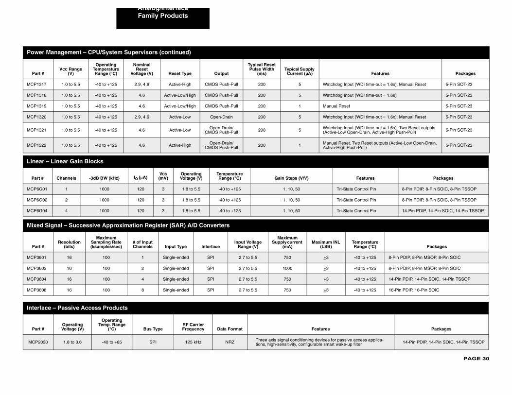
PAGE 30
Analog/Interface
MCP13 DI time-out = 1.6s), Manual Reset 5-Pin SOT-23
MCP13 DI time-out = 1.6s) 5-Pin SOT-23
MCP13 5-Pin SOT-23
MCP13 DI time-out = 1.6x), Manual Reset 5-Pin SOT-23
MCP13 DI time-out = 1.6s), Two Reset outputs rain, Active-High Push-Pull) 5-Pin SOT-23
MCP13 Reset outputs (Active-Low Open-Drain, ull) 5-Pin SOT-23
Linea
Part atures Packages
MCP6G trol Pin 8-Pin PDIP, 8-Pin SOIC, 8-Pin TSSOP
MCP6G trol Pin 8-Pin PDIP, 8-Pin SOIC, 8-Pin TSSOP
MCP6G trol Pin 14-Pin PDIP, 14-Pin SOIC, 14-Pin TSSOP
Mixed
Part perature ge (°C) Packages
MCP36 to +125 8-Pin PDIP, 8-Pin MSOP, 8-Pin SOIC
MCP36 to +125 8-Pin PDIP, 8-Pin MSOP, 8-Pin SOIC
MCP36 to +125 14-Pin PDIP, 14-Pin SOIC, 14-Pin TSSOP
MCP36 to +125 16-Pin PDIP, 16-Pin SOIC
Interf
Part Packages
MCP20 ss applica-r 14-Pin PDIP, 14-Pin SOIC, 14-Pin TSSOP
Powe
Part Features Packages
Family Products
17 1.0 to 5.5 -40 to +125 2.9, 4.6 Active-High CMOS Push-Pull 200 5 Watchdog Input (W
18 1.0 to 5.5 -40 to +125 4.6 Active-Low/High CMOS Push-Pull 200 5 Watchdog Input (W
19 1.0 to 5.5 -40 to +125 4.6 Active-Low/High CMOS Push-Pull 200 1 Manual Reset
20 1.0 to 5.5 -40 to +125 2.9, 4.6 Active-Low Open-Drain 200 5 Watchdog Input (W
21 1.0 to 5.5 -40 to +125 4.6 Active-Low Open-Drain/CMOS Push-Pull 200 5 Watchdog Input (W
(Active-Low Open-D
22 1.0 to 5.5 -40 to +125 4.6 Active-High Open-Drain/CMOS Push-Pull 200 1 Manual Reset, Two
Active-High Push-P
r – Linear Gain Blocks
# Channels -3dB BW (kHz) IQ (μA)VOS (mV)
Operating Voltage (V)
Temperature Range (°C) Gain Steps (V/V) Fe
01 1 1000 120 3 1.8 to 5.5 -40 to +125 1, 10, 50 Tri-State Con
02 2 1000 120 3 1.8 to 5.5 -40 to +125 1, 10, 50 Tri-State Con
04 4 1000 120 3 1.8 to 5.5 -40 to +125 1, 10, 50 Tri-State Con
Signal – Successive Approximation Register (SAR) A/D Converters
#Resolution
(bits)
Maximum Sampling Rate (ksamples/sec)
# of Input Channels Input Type Interface
Input Voltage Range (V)
Maximum Supply current
(mA)Maximum INL
(LSB)TemRan
01 16 100 1 Single-ended SPI 2.7 to 5.5 750 +3 -40
02 16 100 2 Single-ended SPI 2.7 to 5.5 1000 +3 -40
04 16 100 4 Single-ended SPI 2.7 to 5.5 750 +3 -40
08 16 100 8 Single-ended SPI 2.7 to 5.5 750 +3 -40
ace – Passive Access Products
#Operating Voltage (V)
Operating Temp. Range
(°C) Bus TypeRF Carrier Frequency Data Format Features
30 1.8 to 3.6 -40 to +85 SPI 125 kHz NRZ Three axis signal conditioning devices for passive accetions, high-sensitivity, configurable smart wake-up filte
r Management – CPU/System Supervisors (continued)
#VCC Range
(V)
Operating Temperature Range (°C)
Nominal Reset
Voltage (V) Reset Type Output
Typical Reset Pulse Width
(ms)Typical Supply
Current (µA)
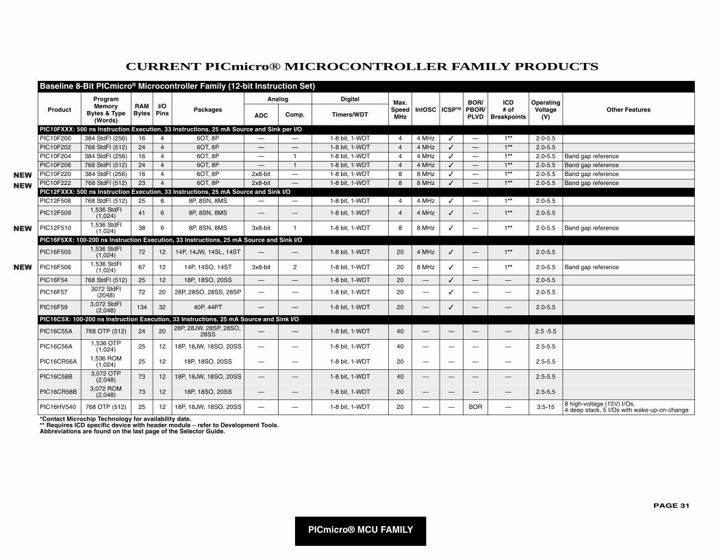
PAGE 31
PRODUCTS
Bas
Pro f oints
Operating Voltage
(V)Other Features
PIC10PIC10 * 2.0-5.5
PIC10 * 2.0-5.5
PIC10 * 2.0-5.5 Band gap reference
PIC10 * 2.0-5.5 Band gap reference
PIC10 * 2.0-5.5 Band gap reference
PIC10 * 2.0-5.5 Band gap reference
PIC12PIC12 * 2.0-5.5
PIC12 * 2.0-5.5
PIC12 * 2.0-5.5 Band gap reference
PIC16
PIC16 * 2.0-5.5
PIC16 * 2.0-5.5 Band gap reference
PIC16 2.0-5.5
PIC16 2.0-5.5
PIC16 2.0-5.5
PIC16
PIC16 2.5 -5.5
PIC16 2.5-5.5
PIC16 2.5-5.5
PIC16 2.5-5.5
PIC16 2.5-5.5
PIC16 3.5-15 8 high-voltage (15V) I/Os, 4 deep stack, 5 I/Os with wake-up-on-change
*Cont** ReqAbbre
NEW
NEW
NEW
NEW
PICmicro® MCU FAMILY
CURRENT PICmicro® MICROCONTROLLER FAMILY
eline 8-Bit PICmicro® Microcontroller Family (12-bit Instruction Set)
duct
Program Memory
Bytes & Type (Words)
RAM Bytes
I/O Pins Packages
Analog Digital Max. Speed MHz
IntOSC ICSPTMBOR/
PBOR/PLVD
ICD# o
BreakpADC Comp. Timers/WDT
FXXX: 500 ns Instruction Execution, 33 Instructions, 25 mA Source and Sink per I/OF200 384 StdFI (256) 16 4 6OT, 8P — — 1-8 bit, 1-WDT 4 4 MHz ✓ — 1*F202 768 StdFI (512) 24 4 6OT, 8P — — 1-8 bit, 1-WDT 4 4 MHz ✓ — 1*F204 384 StdFI (256) 16 4 6OT, 8P — 1 1-8 bit, 1-WDT 4 4 MHz ✓ — 1*F206 768 StdFI (512) 24 4 6OT, 8P — 1 1-8 bit, 1-WDT 4 4 MHz ✓ — 1*F220 384 StdFl (256) 16 4 6OT, 8P 2x8-bit — 1-8 bit, 1-WDT 8 8 MHz ✓ — 1*F222 768 StdFl (512) 23 4 6OT, 8P 2x8-bit — 1-8 bit, 1-WDT 8 8 MHz ✓ — 1*FXXX: 500 ns Instruction Execution, 33 Instructions, 25 mA Source and Sink I/OF508 768 StdFI (512) 25 6 8P, 8SN, 8MS — — 1-8 bit, 1-WDT 4 4 MHz ✓ — 1*
F509 1,536 StdFI (1,024) 41 6 8P, 8SN, 8MS — — 1-8 bit, 1-WDT 4 4 MHz ✓ — 1*
F510 1,536 StdFI (1,024) 38 6 8P, 8SN, 8MS 3x8-bit 1 1-8 bit, 1-WDT 8 8 MHz ✓ — 1*
F5XX: 100-200 ns Instruction Execution, 33 Instructions, 25 mA Source and Sink I/O
F505 1,536 StdFI (1,024) 72 12 14P, 14JW, 14SL, 14ST — — 1-8 bit, 1-WDT 20 4 MHz ✓ — 1*
F506 1,536 StdFl (1,024) 67 12 14P, 14SO, 14ST 3x8-bit 2 1-8 bit, 1-WDT 20 8 MHz ✓ — 1*
F54 768 StdFI (512) 25 12 18P, 18SO, 20SS — — 1-8 bit, 1-WDT 20 — ✓ — —
F57 3072 StdFI (2048) 72 20 28P, 28SO, 28SS, 28SP — — 1-8 bit, 1-WDT 20 — ✓ — —
F59 3,072 StdFI (2,048) 134 32 40P, 44PT — — 1-8 bit, 1-WDT 20 — ✓ — —
C5X: 100-200 ns Instruction Execution, 33 Instructions, 25 mA Source and Sink I/O
C55A 768 OTP (512) 24 20 28P, 28JW, 28SP, 28SO, 28SS — — 1-8 bit, 1-WDT 40 — — — —
C56A 1,536 OTP (1,024) 25 12 18P, 18JW, 18SO, 20SS — — 1-8 bit, 1-WDT 40 — — — —
CR56A 1,536 ROM (1,024) 25 12 18P, 18SO, 20SS — — 1-8 bit, 1-WDT 20 — — — —
C58B 3,072 OTP (2,048) 73 12 18P, 18JW, 18SO, 20SS — — 1-8 bit, 1-WDT 40 — — — —
CR58B 3,072 ROM (2,048) 73 12 18P, 18SO, 20SS — — 1-8 bit, 1-WDT 20 — — — —
HV540 768 OTP (512) 25 12 18P, 18JW, 18SO, 20SS — — 1-8 bit, 1-WDT 20 — — BOR —
act Microchip Technology for availability date.uires ICD specific device with header module – refer to Development Tools.viations are found on the last page of the Selector Guide.
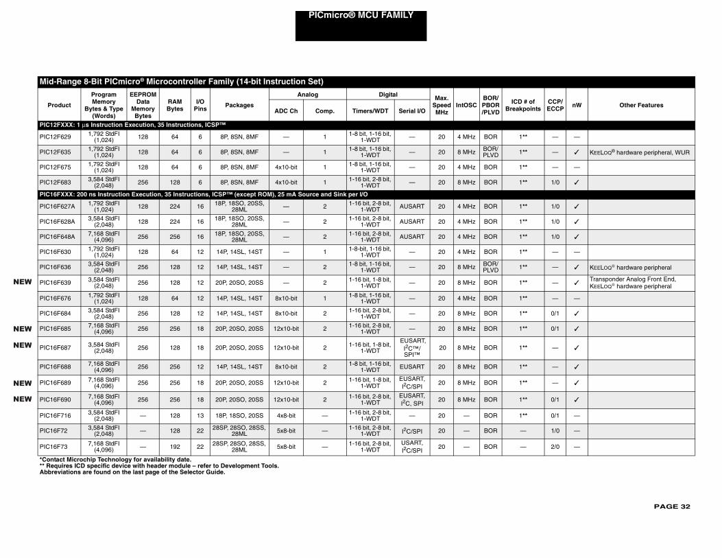
PAGE 32
PICmicro® MCU FAMILY
Mid-R
Pro ICD # of Breakpoints
CCP/ECCP nW Other Features
PIC12F
PIC12F 1** — —
PIC12F 1** — ✓ KEELOQ® hardware peripheral, WUR
PIC12F 1** — —
PIC12F 1** 1/0 ✓
PIC16F
PIC16F 1** 1/0 ✓
PIC16F 1** 1/0 ✓
PIC16F 1** 1/0 ✓
PIC16F 1** — —
PIC16F 1** — ✓ KEELOQ® hardware peripheral
PIC16F 1** — ✓Transponder Analog Front End, KEELOQ® hardware peripheral
PIC16F 1** — —
PIC16F 1** 0/1 ✓
PIC16F 1** 0/1 ✓
PIC16F 1** — ✓
PIC16F 1** — ✓
PIC16F 1** — ✓
PIC16F 1** 0/1 ✓
PIC16F 1** 0/1 —
PIC16F — 1/0 —
PIC16F — 2/0 —
*Conta** ReqAbbre
NEW
NEW
NEW
NEW
NEW
ange 8-Bit PICmicro® Microcontroller Family (14-bit Instruction Set)
duct
Program Memory
Bytes & Type (Words)
EEPROM Data
Memory Bytes
RAM Bytes
I/O Pins Packages
Analog Digital Max. Speed MHz
IntOSCBOR/PBOR/PLVDADC Ch Comp. Timers/WDT Serial I/O
XXX: 1 μs Instruction Execution, 35 Instructions, ICSP™
629 1,792 StdFI (1,024) 128 64 6 8P, 8SN, 8MF — 1 1-8 bit, 1-16 bit,
1-WDT — 20 4 MHz BOR
635 1,792 StdFI (1,024) 128 64 6 8P, 8SN, 8MF — 1 1-8 bit, 1-16 bit,
1-WDT — 20 8 MHz BOR/PLVD
675 1,792 StdFI (1,024) 128 64 6 8P, 8SN, 8MF 4x10-bit 1 1-8 bit, 1-16 bit,
1-WDT — 20 4 MHz BOR
683 3,584 StdFI (2,048) 256 128 6 8P, 8SN, 8MF 4x10-bit 1 1-16 bit, 2-8 bit,
1-WDT — 20 8 MHz BOR
XXX: 200 ns Instruction Execution, 35 Instructions, ICSP™ (except ROM), 25 mA Source and Sink per I/O
627A 1,792 StdFI (1,024) 128 224 16 18P, 18SO, 20SS,
28ML — 2 1-16 bit, 2-8 bit, 1-WDT AUSART 20 4 MHz BOR
628A 3,584 StdFI (2,048) 128 224 16 18P, 18SO, 20SS,
28ML — 2 1-16 bit, 2-8 bit, 1-WDT AUSART 20 4 MHz BOR
648A 7,168 StdFI (4,096) 256 256 16 18P, 18SO, 20SS,
28ML — 2 1-16 bit, 2-8 bit, 1-WDT AUSART 20 4 MHz BOR
630 1,792 StdFI (1,024) 128 64 12 14P, 14SL, 14ST — 1 1-8-bit, 1-16 bit,
1-WDT — 20 4 MHz BOR
636 3,584 StdFI (2,048) 256 128 12 14P, 14SL, 14ST — 2 1-8 bit, 1-16 bit,
1-WDT — 20 8 MHz BOR/PLVD
639 3,584 StdFl (2,048) 256 128 12 20P, 20SO, 20SS — 2 1-16 bit, 1-8 bit,
1-WDT — 20 8 MHz BOR
676 1,792 StdFI (1,024) 128 64 12 14P, 14SL, 14ST 8x10-bit 1 1-8 bit, 1-16 bit,
1-WDT — 20 4 MHz BOR
684 3,584 StdFI (2,048) 256 128 12 14P, 14SL, 14ST 8x10-bit 2 1-16 bit, 2-8 bit,
1-WDT — 20 8 MHz BOR
685 7,168 StdFl (4,096) 256 256 18 20P, 20SO, 20SS 12x10-bit 2 1-16 bit, 2-8 bit,
1-WDT — 20 8 MHz BOR
687 3,584 StdFl (2,048) 256 128 18 20P, 20SO, 20SS 12x10-bit 2 1-16 bit, 1-8 bit,
1-WDT
EUSART, I2C™/SPI™
20 8 MHz BOR
688 7,168 StdFI (4,096) 256 256 12 14P, 14SL, 14ST 8x10-bit 2 1-8 bit, 1-16 bit,
1-WDT EUSART 20 8 MHz BOR
689 7,168 StdFl (4,096) 256 256 18 20P, 20SO, 20SS 12x10-bit 2 1-16 bit, 1-8 bit,
1-WDTEUSART, I2C/SPI
20 8 MHz BOR
690 7,168 StdFl (4,096) 256 256 18 20P, 20SO, 20SS 12x10-bit 2 1-16 bit, 2-8 bit,
1-WDTEUSART, I2C, SPI
20 8 MHz BOR
716 3,584 StdFI (2,048) — 128 13 18P, 18SO, 20SS 4x8-bit — 1-16 bit, 2-8 bit,
1-WDT — 20 — BOR
72 3,584 StdFI (2,048) — 128 22 28SP, 28SO, 28SS,
28ML 5x8-bit — 1-16 bit, 2-8 bit, 1-WDT I2C/SPI 20 — BOR
73 7,168 StdFI (4,096) — 192 22 28SP, 28SO, 28SS,
28ML 5x8-bit — 1-16 bit, 2-8 bit, 1-WDT
USART, I2C/SPI
20 — BOR
ct Microchip Technology for availability date.uires ICD specific device with header module – refer to Development Tools.viations are found on the last page of the Selector Guide.
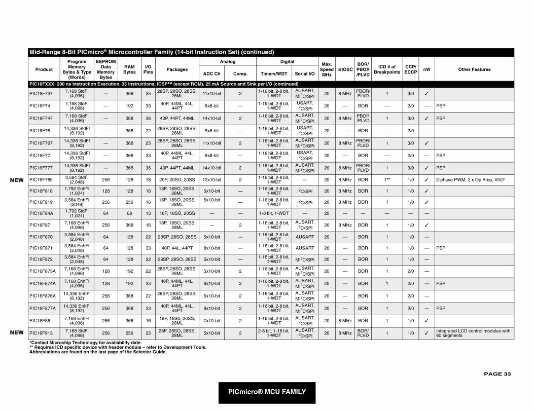
PAGE 33
PIC16F
PIC16F 1 3/0 ✓
PIC16F — 2/0 — PSP
PIC16F 1 3/0 ✓ PSP
PIC16F — 2/0 —
PIC16F 1 3/0 ✓
PIC16F — 2/0 — PSP
PIC16F 1 3/0 ✓ PSP
PIC16F 1** 1/0 ✓ 2-phase PWM, 2 x Op Amp, VREF
PIC16F 1 1/0 ✓
PIC16F 1 1/0 ✓
PIC16F — — —
PIC16F 1 1/0 ✓
PIC16F 1 1/0 —
PIC16F 1 1/0 — PSP
PIC16F 1 1/0 —
PIC16F 1 2/0 —
PIC16F 1 2/0 — PSP
PIC16F 1 2/0 —
PIC16F 1 2/0 — PSP
PIC16F 1 1/0 ✓
PIC16F 1 1/0 ✓Integrated LCD control modules with 60 segments
Mid-R
Pro ICD # of Breakpoints
CCP/ECCP nW Other Features
*Conta** ReqAbbre
NEW
NEW
PICmicro® MCU FAMILY
XXX: 200 ns Instruction Execution, 35 Instructions, ICSP™ (except ROM), 25 mA Source and Sink per I/O (continued)
737 7,168 StdFI (4,096) — 368 25 28SP, 28SO, 28SS,
28ML 11x10-bit 2 1-16 bit, 2-8 bit, 1-WDT
AUSART, MI2C/SPI
20 8 MHz PBOR/PLVD
74 7,168 StdFI (4,096) — 192 33 40P, 44ML, 44L,
44PT 8x8-bit — 1-16 bit, 2-8 bit, 1-WDT
USART, I2C/SPI
20 — BOR
747 7,168 StdFl (4,096) — 368 36 40P, 44PT, 44ML 14x10-bit 2 1-16 bit, 2-8 bit,
1-WDTAUSART, MI2C/SPI
20 8 MHz PBOR/PLVD
76 14,336 StdFI (8,192) — 368 22 28SP, 28SO, 28SS,
28ML 5x8-bit — 1-16 bit, 2-8 bit, 1-WDT
USART, I2C/SPI
20 — BOR
767 14,336 StdFI (8,192) — 368 25 28SP, 28SO, 28SS,
28ML 11x10-bit 2 1-16 bit, 2-8 bit, 1-WDT
AUSART, MI2C/SPI
20 8 MHz PBOR/PLVD
77 14,336 StdFI (8,192) — 368 33 40P, 44ML, 44L,
44PT 8x8-bit — 1-16 bit, 2-8 bit, 1-WDT
USART, I2C/SPI
20 — BOR
777 14,336 StdFI (8,192) — 368 36 40P, 44PT, 44ML 14x10-bit 2 1-16 bit, 2-8 bit,
1-WDTAUSART, MI2C/SPI
20 8 MHz PBOR/PLVD
785 3,584 StdFl (2,048) 256 128 18 20P, 20SO, 20SS 12x10-bit 2 1-16 bit, 2-8 bit,
1-WDT — 20 8 MHz BOR
818 1,792 EnhFI (1,024) 128 128 16 18P, 18SO, 20SS,
28ML 5x10-bit — 1-16 bit, 2-8 bit, 1-WDT I2C/SPI 20 8 MHz BOR
819 3,584 EnhFI (2048) 256 256 16 18P, 18SO, 20SS,
28ML5x10-bit — 1-16 bit, 2-8 bit,
1-WDT I2C/SPI 20 8 MHz BOR
84A 1,792 StdFI (1,024) 64 68 13 18P, 18SO, 20SS — — 1-8 bit, 1-WDT — 20 — —
87 7,168 EnhFI (4,096) 256 368 16 18P, 18SO, 20SS,
28ML — 2 1-16 bit, 2-8 bit, 1-WDT
AUSART, I2C/SPI
20 8 MHz BOR
870 3,584 EnhFI (2,048) 64 128 22 28SP, 28SO, 28SS 5x10-bit — 1-16 bit, 2-8 bit,
1-WDT AUSART 20 — BOR
871 3,584 EnhFI (2,048) 64 128 33 40P, 44L, 44PT 8x10-bit — 1-16 bit, 2-8 bit,
1-WDT AUSART 20 — BOR
872 3,584 EnhFI (2,048) 64 128 22 28SP, 28SO, 28SS 5x10-bit — 1-16 bit, 2-8 bit,
1-WDT MI2C/SPI 20 — BOR
873A 7,168 EnhFI (4,096) 128 192 22 28SP, 28SO, 28SS,
28ML 5x10-bit 2 1-16 bit, 2-8 bit, 1-WDT
AUSART, MI2C/SPI
20 — BOR
874A 7,168 EnhFI (4,096) 128 192 33 40P, 44ML, 44L,
44PT 8x10-bit 2 1-16 bit, 2-8 bit, 1-WDT
AUSART, MI2C/SPI
20 — BOR
876A 14,336 EnhFI (8,192) 256 368 22 28SP, 28SO, 28SS,
28ML 5x10-bit 2 1-16 bit, 2-8 bit, 1-WDT
AUSART, MI2C/SPI
20 — BOR
877A 14,336 EnhFI (8,192) 256 368 33 40P, 44ML, 44L,
44PT 8x10-bit 2 1-16 bit, 2-8 bit, 1-WDT
AUSART, MI2C/SPI
20 — BOR
88 7,168 EnhFI (4,096) 256 368 16 18P, 18S0, 20SS,
28ML 7x10-bit 2 1-16 bit, 2-8 bit, 1-WDT
AUSART, I2C/SPI
20 8 MHz BOR
913 7,168 StdFl (4,096) 256 256 25 28P, 28SO, 28SS,
28ML 5x10-bit 2 2-8 bit, 1-16 bit, 1-WDT
AUSART, I2C/SPI
20 8 MHz BOR/PLVD
ange 8-Bit PICmicro® Microcontroller Family (14-bit Instruction Set) (continued)
duct
Program Memory
Bytes & Type (Words)
EEPROM Data
Memory Bytes
RAM Bytes
I/O Pins Packages
Analog Digital Max. Speed MHz
IntOSCBOR/PBOR/PLVDADC Ch Comp. Timers/WDT Serial I/O
ct Microchip Technology for availability date.uires ICD specific device with header module – refer to Development Tools.viations are found on the last page of the Selector Guide.
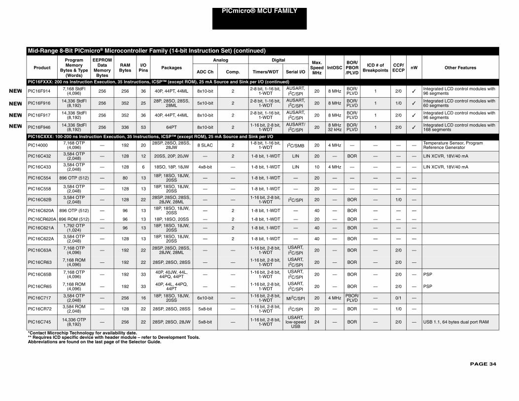
PAGE 34
PICmicro® MCU FAMILY
PIC16F
PIC16F 1 2/0 ✓Integrated LCD control modules with 96 segments
PIC16F 1 1/0 ✓Integrated LCD control modules with 60 segments
PIC16F 1 2/0 ✓Integrated LCD control modules with 96 segments
PIC16F 1 2/0 ✓Integrated LCD control modules with 168 segments
PIC16C
PIC140 — — — Temperature Sensor, Program Reference Generator
PIC16C — — — LIN XCVR, 18V/40 mA
PIC16C — — — LIN XCVR, 18V/40 mA
PIC16C — — —
PIC16C — — —
PIC16C — 1/0 —
PIC16C — — —
PIC16C — — —
PIC16C — — —
PIC16C — — —
PIC16C — 2/0 —
PIC16C — 2/0 —
PIC16C — 2/0 — PSP
PIC16C — 2/0 — PSP
PIC16C — 0/1 —
PIC16C — 1/0 —
PIC16C — 2/0 — USB 1.1, 64 bytes dual port RAM
Mid-R
Prod ICD # of Breakpoints
CCP/ECCP nW Other Features
*Conta** RequAbbrev
NEW
NEW
NEW
NEW
XXX: 200 ns Instruction Execution, 35 Instructions, ICSP™ (except ROM), 25 mA Source and Sink per I/O (continued)
914 7,168 StdFl (4,096) 256 256 36 40P, 44PT, 44ML 8x10-bit 2 2-8 bit, 1-16 bit,
1-WDTAUSART, I2C/SPI
20 8 MHz BOR/PLVD
916 14,336 StdFl (8,192) 256 352 25 28P, 28SO, 28SS,
28ML 5x10-bit 2 2-8 bit, 1-16 bit, 1-WDT
AUSART, I2C/SPI
20 8 MHz BOR/PLVD
917 14,336 StdFl (8,192) 256 352 36 40P, 44PT, 44ML 8x10-bit 2 2-8 bit, 1-16 bit,
1-WDTAUSART, I2C/SPI
20 8 MHz BOR/PLVD
946 14,336 StdFl (8,192) 256 336 53 64PT 8x10-bit 2 1-16 bit, 2-8 bit,
1-WDTAUSART/I2C/SPI
20 8 MHz32 kHz
BOR/PLVD
XXX: 100-200 ns Instruction Execution, 35 Instructions, ICSP™ (except ROM), 25 mA Source and Sink per I/O
00 7,168 OTP (4,096) — 192 20 28SP, 28SO, 28SS,
28JW 8 SLAC 2 1-8 bit, 1-16 bit, 1-WDT I2C/SMB 20 4 MHz —
432 3,584 OTP (2,048) — 128 12 20SS, 20P, 20JW — 2 1-8 bit, 1-WDT LIN 20 — BOR
433 3,584 OTP (2,048) — 128 6 18SO, 18P, 18JW 4x8-bit — 1-8 bit, 1-WDT LIN 10 4 MHz —
554 896 OTP (512) — 80 13 18P, 18SO, 18JW, 20SS — — 1-8 bit, 1-WDT — 20 — —
558 3,584 OTP (2,048) — 128 13 18P, 18SO, 18JW,
20SS — — 1-8 bit, 1-WDT — 20 — —
62B 3,584 OTP (2,048) — 128 22 28SP, 28SO, 28SS,
28JW, 28ML — — 1-16 bit, 2-8 bit, 1-WDT I2C/SPI 20 — BOR
620A 896 OTP (512) — 96 13 18P, 18SO, 18JW, 20SS — 2 1-8 bit, 1-WDT — 40 — BOR
R620A 896 ROM (512) — 96 13 18P, 18SO, 20SS — 2 1-8 bit, 1-WDT — 20 — BOR
621A 1,792 OTP (1,024) — 96 13 18P, 18SO, 18JW,
20SS — 2 1-8 bit, 1-WDT — 40 — BOR
622A 3,584 OTP (2,048) — 128 13 18P, 18SO, 18JW,
20SS — 2 1-8 bit, 1-WDT — 40 — BOR
63A 7,168 OTP (4,096) — 192 22 28SP, 28SO, 28SS,
28JW, 28ML — — 1-16 bit, 2-8 bit, 1-WDT
USART, I2C/SPI
20 — BOR
R63 7,168 ROM (4,096) — 192 22 28SP, 28SO, 28SS — — 1-16 bit, 2-8 bit,
1-WDTUSART, I2C/SPI
20 — BOR
65B 7,168 OTP (4,096) — 192 33 40P, 40JW, 44L,
44PQ, 44PT — — 1-16 bit, 2-8 bit, 1-WDT
USART, I2C/SPI
20 — BOR
R65 7,168 ROM (4,096) — 192 33 40P, 44L, 44PQ,
44PT — — 1-16 bit, 2-8 bit, 1-WDT
USART, I2C/SPI
20 — BOR
717 3,584 OTP (2,048) — 256 16 18P, 18SO, 18JW,
20SS 6x10-bit — 1-16 bit, 2-8 bit, 1-WDT MI2C/SPI 20 4 MHz PBOR/
PLVD
R72 3,584 ROM (2,048) — 128 22 28SP, 28SO, 28SS 5x8-bit — 1-16 bit, 2-8 bit,
1-WDT I2C/SPI 20 — BOR
745 14,336 OTP (8,192) — 256 22 28SP, 28SO, 28JW 5x8-bit — 1-16 bit, 2-8 bit,
1-WDT
USART, low-speed
USB24 — BOR
ange 8-Bit PICmicro® Microcontroller Family (14-bit Instruction Set) (continued)
uct
Program Memory
Bytes & Type (Words)
EEPROM Data
Memory Bytes
RAM Bytes
I/O Pins Packages
Analog Digital Max. Speed MHz
IntOSCBOR/PBOR/PLVDADC Ch Comp. Timers/WDT Serial I/O
ct Microchip Technology for availability date.ires ICD specific device with header module – refer to Development Tools.iations are found on the last page of the Selector Guide.
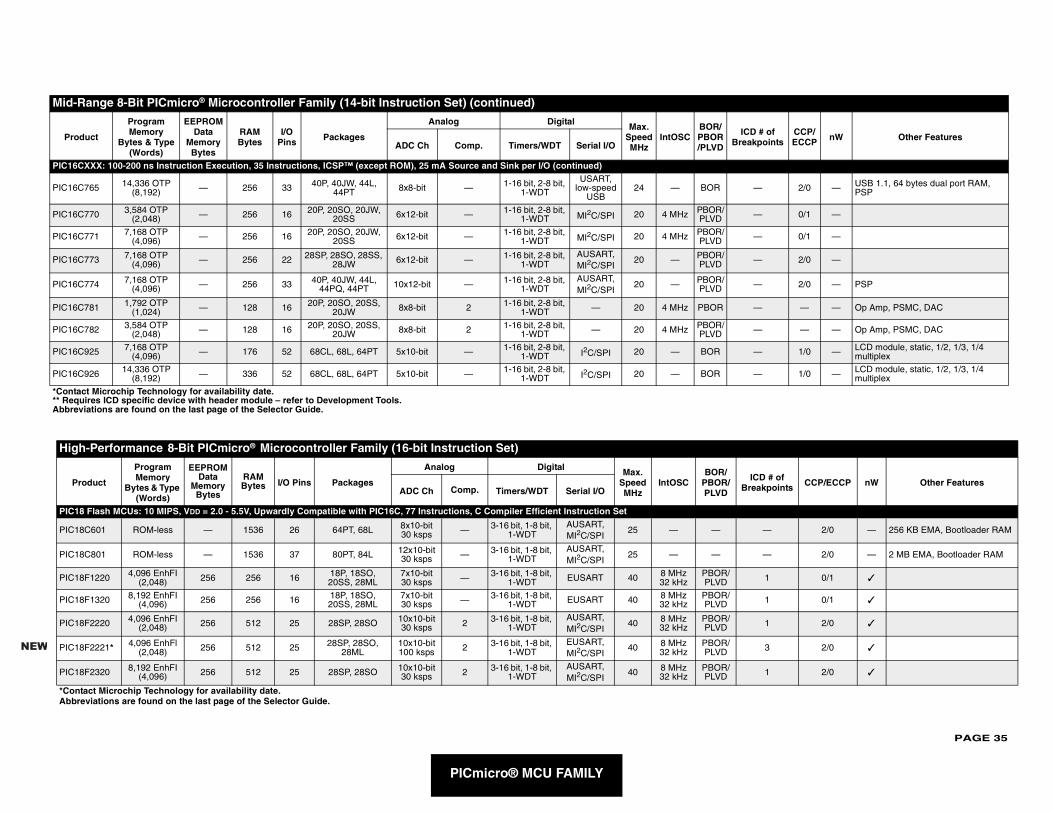
PAGE 35
PIC16C
PIC16C — 2/0 — USB 1.1, 64 bytes dual port RAM, PSP
PIC16C — 0/1 —
PIC16C — 0/1 —
PIC16C — 2/0 —
PIC16C — 2/0 — PSP
PIC16C — — — Op Amp, PSMC, DAC
PIC16C — — — Op Amp, PSMC, DAC
PIC16C — 1/0 — LCD module, static, 1/2, 1/3, 1/4 multiplex
PIC16C — 1/0 — LCD module, static, 1/2, 1/3, 1/4 multiplex
High
Pro ICD # of Breakpoints CCP/ECCP nW Other Features
PIC18
PIC18 — 2/0 — 256 KB EMA, Bootloader RAM
PIC18 — 2/0 — 2 MB EMA, Bootloader RAM
PIC18 1 0/1 ✓
PIC18 1 0/1 ✓
PIC18 1 2/0 ✓
PIC18 3 2/0 ✓
PIC18 1 2/0 ✓
*ContaAbbre
Mid-R
Prod ICD # of reakpoints
CCP/ECCP nW Other Features
*Contac** RequAbbrevi
NEW
PICmicro® MCU FAMILY
XXX: 100-200 ns Instruction Execution, 35 Instructions, ICSP™ (except ROM), 25 mA Source and Sink per I/O (continued)
765 14,336 OTP (8,192) — 256 33 40P, 40JW, 44L,
44PT 8x8-bit — 1-16 bit, 2-8 bit, 1-WDT
USART, low-speed
USB24 — BOR
770 3,584 OTP (2,048) — 256 16 20P, 20SO, 20JW,
20SS 6x12-bit — 1-16 bit, 2-8 bit, 1-WDT MI2C/SPI 20 4 MHz PBOR/
PLVD
771 7,168 OTP (4,096) — 256 16 20P, 20SO, 20JW,
20SS 6x12-bit — 1-16 bit, 2-8 bit, 1-WDT MI2C/SPI 20 4 MHz PBOR/
PLVD
773 7,168 OTP (4,096) — 256 22 28SP, 28SO, 28SS,
28JW 6x12-bit — 1-16 bit, 2-8 bit, 1-WDT
AUSART, MI2C/SPI
20 — PBOR/PLVD
774 7,168 OTP (4,096) — 256 33 40P, 40JW, 44L,
44PQ, 44PT 10x12-bit — 1-16 bit, 2-8 bit, 1-WDT
AUSART, MI2C/SPI
20 — PBOR/PLVD
781 1,792 OTP (1,024) — 128 16 20P, 20SO, 20SS,
20JW 8x8-bit 2 1-16 bit, 2-8 bit, 1-WDT — 20 4 MHz PBOR
782 3,584 OTP (2,048) — 128 16 20P, 20SO, 20SS,
20JW 8x8-bit 2 1-16 bit, 2-8 bit, 1-WDT — 20 4 MHz PBOR/
PLVD
925 7,168 OTP (4,096) — 176 52 68CL, 68L, 64PT 5x10-bit — 1-16 bit, 2-8 bit,
1-WDT I2C/SPI 20 — BOR
926 14,336 OTP (8,192) — 336 52 68CL, 68L, 64PT 5x10-bit — 1-16 bit, 2-8 bit,
1-WDT I2C/SPI 20 — BOR
-Performance 8-Bit PICmicro® Microcontroller Family (16-bit Instruction Set)
duct
Program Memory
Bytes & Type (Words)
EEPROM Data
Memory Bytes
RAM Bytes I/O Pins Packages
Analog Digital Max. Speed MHz
IntOSCBOR/
PBOR/PLVDADC Ch Comp. Timers/WDT Serial I/O
Flash MCUs: 10 MIPS, VDD = 2.0 - 5.5V, Upwardly Compatible with PIC16C, 77 Instructions, C Compiler Efficient Instruction Set
C601 ROM-less — 1536 26 64PT, 68L 8x10-bit30 ksps — 3-16 bit, 1-8 bit,
1-WDTAUSART, MI2C/SPI
25 — —
C801 ROM-less — 1536 37 80PT, 84L 12x10-bit30 ksps — 3-16 bit, 1-8 bit,
1-WDTAUSART, MI2C/SPI
25 — —
F1220 4,096 EnhFI (2,048) 256 256 16 18P, 18SO,
20SS, 28ML7x10-bit30 ksps — 3-16 bit, 1-8 bit,
1-WDT EUSART 40 8 MHz32 kHz
PBOR/PLVD
F1320 8,192 EnhFI (4,096) 256 256 16 18P, 18SO,
20SS, 28ML7x10-bit30 ksps — 3-16 bit, 1-8 bit,
1-WDT EUSART 40 8 MHz32 kHz
PBOR/PLVD
F2220 4,096 EnhFI (2,048) 256 512 25 28SP, 28SO 10x10-bit
30 ksps 2 3-16 bit, 1-8 bit, 1-WDT
AUSART, MI2C/SPI
40 8 MHz32 kHz
PBOR/PLVD
F2221* 4,096 EnhFl (2,048) 256 512 25 28SP, 28SO,
28ML10x10-bit100 ksps 2 3-16 bit, 1-8 bit,
1-WDTEUSART, MI2C/SPI
40 8 MHz32 kHz
PBOR/PLVD
F2320 8,192 EnhFI(4,096) 256 512 25 28SP, 28SO 10x10-bit
30 ksps 2 3-16 bit, 1-8 bit, 1-WDT
AUSART, MI2C/SPI
40 8 MHz32 kHz
PBOR/PLVD
ct Microchip Technology for availability date.viations are found on the last page of the Selector Guide.
ange 8-Bit PICmicro® Microcontroller Family (14-bit Instruction Set) (continued)
uct
Program Memory
Bytes & Type (Words)
EEPROM Data
Memory Bytes
RAM Bytes
I/O Pins Packages
Analog Digital Max. Speed MHz
IntOSCBOR/PBOR/PLVD BADC Ch Comp. Timers/WDT Serial I/O
t Microchip Technology for availability date.ires ICD specific device with header module – refer to Development Tools.ations are found on the last page of the Selector Guide.
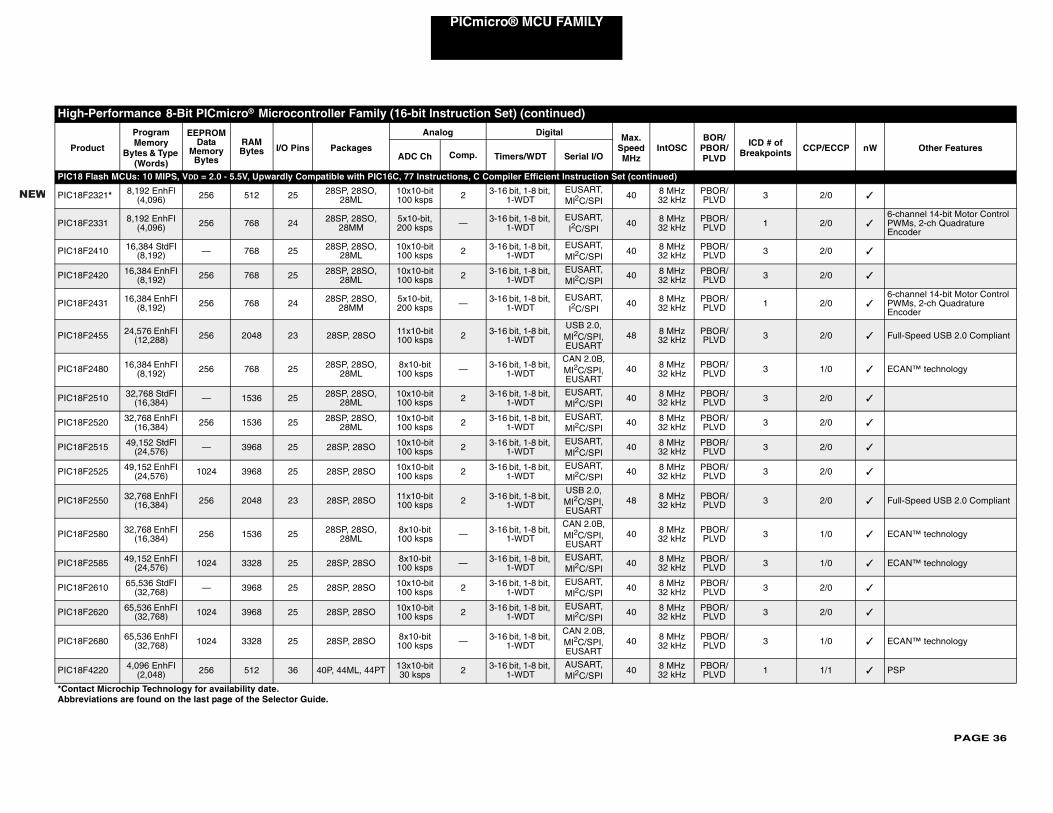
PAGE 36
PICmicro® MCU FAMILY
PIC18
PIC18F 3 2/0 ✓
PIC18F 1 2/0 ✓6-channel 14-bit Motor Control PWMs, 2-ch Quadrature Encoder
PIC18F 3 2/0 ✓
PIC18F 3 2/0 ✓
PIC18F 1 2/0 ✓6-channel 14-bit Motor Control PWMs, 2-ch Quadrature Encoder
PIC18F 3 2/0 ✓ Full-Speed USB 2.0 Compliant
PIC18F 3 1/0 ✓ ECAN™ technology
PIC18F 3 2/0 ✓
PIC18F 3 2/0 ✓
PIC18F 3 2/0 ✓
PIC18F 3 2/0 ✓
PIC18F 3 2/0 ✓ Full-Speed USB 2.0 Compliant
PIC18F 3 1/0 ✓ ECAN™ technology
PIC18F 3 1/0 ✓ ECAN™ technology
PIC18F 3 2/0 ✓
PIC18F 3 2/0 ✓
PIC18F 3 1/0 ✓ ECAN™ technology
PIC18F 1 1/1 ✓ PSP
High
Pro ICD # of Breakpoints CCP/ECCP nW Other Features
*ContaAbbrev
NEW
Flash MCUs: 10 MIPS, VDD = 2.0 - 5.5V, Upwardly Compatible with PIC16C, 77 Instructions, C Compiler Efficient Instruction Set (continued)
2321* 8,192 EnhFl (4,096) 256 512 25 28SP, 28SO,
28ML10x10-bit100 ksps 2 3-16 bit, 1-8 bit,
1-WDTEUSART, MI2C/SPI
40 8 MHz32 kHz
PBOR/PLVD
2331 8,192 EnhFI (4,096) 256 768 24 28SP, 28SO,
28MM5x10-bit, 200 ksps — 3-16 bit, 1-8 bit,
1-WDTEUSART, I2C/SPI
40 8 MHz32 kHz
PBOR/PLVD
2410 16,384 StdFI (8,192) — 768 25 28SP, 28SO,
28ML10x10-bit100 ksps 2 3-16 bit, 1-8 bit,
1-WDTEUSART, MI2C/SPI
40 8 MHz32 kHz
PBOR/PLVD
2420 16,384 EnhFI (8,192) 256 768 25 28SP, 28SO,
28ML10x10-bit100 ksps 2 3-16 bit, 1-8 bit,
1-WDTEUSART, MI2C/SPI
40 8 MHz32 kHz
PBOR/PLVD
2431 16,384 EnhFI (8,192) 256 768 24 28SP, 28SO,
28MM5x10-bit, 200 ksps — 3-16 bit, 1-8 bit,
1-WDTEUSART, I2C/SPI
40 8 MHz32 kHz
PBOR/PLVD
2455 24,576 EnhFI (12,288) 256 2048 23 28SP, 28SO 11x10-bit
100 ksps 2 3-16 bit, 1-8 bit, 1-WDT
USB 2.0, MI2C/SPI, EUSART
48 8 MHz32 kHz
PBOR/PLVD
2480 16,384 EnhFI (8,192) 256 768 25 28SP, 28SO,
28ML8x10-bit 100 ksps — 3-16 bit, 1-8 bit,
1-WDT
CAN 2.0B, MI2C/SPI, EUSART
40 8 MHz32 kHz
PBOR/PLVD
2510 32,768 StdFI (16,384) — 1536 25 28SP, 28SO,
28ML10x10-bit 100 ksps 2 3-16 bit, 1-8 bit,
1-WDTEUSART, MI2C/SPI
40 8 MHz32 kHz
PBOR/PLVD
2520 32,768 EnhFI (16,384) 256 1536 25 28SP, 28SO,
28ML10x10-bit 100 ksps 2 3-16 bit, 1-8 bit,
1-WDTEUSART, MI2C/SPI
40 8 MHz32 kHz
PBOR/PLVD
2515 49,152 StdFl (24,576) — 3968 25 28SP, 28SO 10x10-bit
100 ksps 2 3-16 bit, 1-8 bit, 1-WDT
EUSART, MI2C/SPI
40 8 MHz32 kHz
PBOR/PLVD
2525 49,152 EnhFI (24,576) 1024 3968 25 28SP, 28SO 10x10-bit
100 ksps 2 3-16 bit, 1-8 bit, 1-WDT
EUSART, MI2C/SPI
40 8 MHz32 kHz
PBOR/PLVD
2550 32,768 EnhFI (16,384) 256 2048 23 28SP, 28SO 11x10-bit
100 ksps 2 3-16 bit, 1-8 bit, 1-WDT
USB 2.0, MI2C/SPI, EUSART
48 8 MHz32 kHz
PBOR/PLVD
2580 32,768 EnhFI (16,384) 256 1536 25 28SP, 28SO,
28ML8x10-bit 100 ksps — 3-16 bit, 1-8 bit,
1-WDT
CAN 2.0B, MI2C/SPI, EUSART
40 8 MHz32 kHz
PBOR/PLVD
2585 49,152 EnhFI (24,576) 1024 3328 25 28SP, 28SO 8x10-bit
100 ksps — 3-16 bit, 1-8 bit, 1-WDT
EUSART, MI2C/SPI
40 8 MHz32 kHz
PBOR/PLVD
2610 65,536 StdFI (32,768) — 3968 25 28SP, 28SO 10x10-bit
100 ksps 2 3-16 bit, 1-8 bit, 1-WDT
EUSART, MI2C/SPI
40 8 MHz32 kHz
PBOR/PLVD
2620 65,536 EnhFI (32,768) 1024 3968 25 28SP, 28SO 10x10-bit
100 ksps 2 3-16 bit, 1-8 bit, 1-WDT
EUSART, MI2C/SPI
40 8 MHz32 kHz
PBOR/PLVD
2680 65,536 EnhFI (32,768) 1024 3328 25 28SP, 28SO 8x10-bit
100 ksps — 3-16 bit, 1-8 bit, 1-WDT
CAN 2.0B, MI2C/SPI, EUSART
40 8 MHz32 kHz
PBOR/PLVD
4220 4,096 EnhFI (2,048) 256 512 36 40P, 44ML, 44PT 13x10-bit
30 ksps 2 3-16 bit, 1-8 bit, 1-WDT
AUSART, MI2C/SPI
40 8 MHz32 kHz
PBOR/PLVD
-Performance 8-Bit PICmicro® Microcontroller Family (16-bit Instruction Set) (continued)
duct
Program Memory
Bytes & Type (Words)
EEPROM Data
Memory Bytes
RAM Bytes I/O Pins Packages
Analog Digital Max. Speed MHz
IntOSCBOR/
PBOR/PLVDADC Ch Comp. Timers/WDT Serial I/O
ct Microchip Technology for availability date.iations are found on the last page of the Selector Guide.
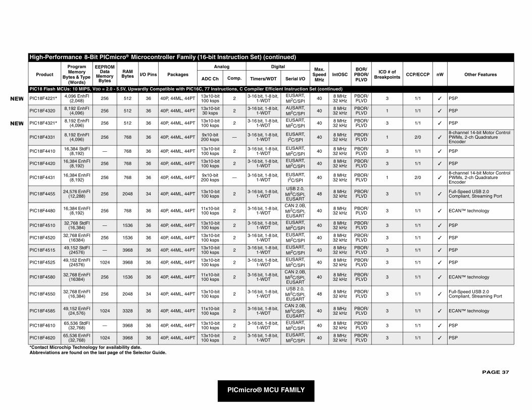
PAGE 37
PIC18
PIC18F 3 1/1 ✓ PSP
PIC18F 1 1/1 ✓ PSP
PIC18F 3 1/1 ✓ PSP
PIC18F 1 2/0 ✓8-channel 14-bit Motor Control PWMs, 2-ch Quadrature Encoder
PIC18F 3 1/1 ✓ PSP
PIC18F 3 1/1 ✓ PSP
PIC18F 1 2/0 ✓8-channel 14-bit Motor Control PWMs, 2-ch Quadrature Encoder
PIC18F 3 1/1 ✓Full-Speed USB 2.0 Compliant, Streaming Port
PIC18F 3 1/1 ✓ ECAN™ technology
PIC18F 3 1/1 ✓ PSP
PIC18F 3 1/1 ✓ PSP
PIC18F 3 1/1 ✓ PSP
PIC18F 3 1/1 ✓ PSP
PIC18F 3 1/1 ✓ ECAN™ technology
PIC18F 3 1/1 ✓Full-Speed USB 2.0 Compliant, Streaming Port
PIC18F 3 1/1 ✓ ECAN™ technology
PIC18F 3 1/1 ✓ PSP
PIC18F 3 1/1 ✓ PSP
High
Pro ICD # of Breakpoints CCP/ECCP nW Other Features
*ContaAbbre
NEW
NEW
PICmicro® MCU FAMILY
Flash MCUs: 10 MIPS, VDD = 2.0 - 5.5V, Upwardly Compatible with PIC16C, 77 Instructions, C Compiler Efficient Instruction Set (continued)
4221* 4,096 EnhFl (2,048) 256 512 36 40P, 44ML, 44PT 13x10-bit
100 ksps 2 3-16 bit, 1-8 bit, 1-WDT
EUSART, MI2C/SPI
40 8 MHz32 kHz
PBOR/PLVD
4320 8,192 EnhFI (4,096) 256 512 36 40P, 44ML, 44PT 13x10-bit
30 ksps 2 3-16 bit, 1-8 bit, 1-WDT
AUSART, MI2C/SPI
40 8 MHz32 kHz
PBOR/PLVD
4321* 8,192 EnhFl (4,096) 256 512 36 40P, 44ML, 44PT 13x10-bit
100 ksps 2 3-16 bit, 1-8 bit, 1-WDT
EUSART, MI2C/SPI
40 8 MHz32 kHz
PBOR/PLVD
4331 8,192 EnhFI (4,096) 256 768 36 40P, 44ML, 44PT 9x10-bit
200 ksps — 3-16 bit, 1-8 bit, 1-WDT
EUSART, I2C/SPI
40 8 MHz32 kHz
PBOR/PLVD
4410 16,384 StdFI (8,192) — 768 36 40P, 44ML, 44PT 13x10-bit
100 ksps 2 3-16 bit, 1-8 bit, 1-WDT
EUSART, MI2C/SPI
40 8 MHz32 kHz
PBOR/PLVD
4420 16,384 EnhFI (8,192) 256 768 36 40P, 44ML, 44PT 13x10-bit
100 ksps 2 3-16 bit, 1-8 bit, 1-WDT
EUSART, MI2C/SPI
40 8 MHz32 kHz
PBOR/PLVD
4431 16,384 EnhFI (8,192) 256 768 36 40P, 44ML, 44PT 9x10-bit
200 ksps — 3-16 bit, 1-8 bit, 1-WDT
EUSART, I2C/SPI
40 8 MHz32 kHz
PBOR/PLVD
4455 24,576 EnhFI (12,288) 256 2048 34 40P, 44ML, 44PT 13x10-bit
100 ksps 2 3-16 bit, 1-8 bit, 1-WDT
USB 2.0, MI2C/SPI, EUSART
48 8 MHz32 kHz
PBOR/PLVD
4480 16,384 EnhFI (8,192) 256 768 36 40P, 44ML, 44PT 11x10-bit
100 ksps 2 3-16 bit, 1-8 bit, 1-WDT
CAN 2.0B, MI2C/SPI, EUSART
40 8 MHz32 kHz
PBOR/PLVD
4510 32,768 StdFl (16,384) — 1536 36 40P, 44ML, 44PT 13x10-bit
100 ksps 2 3-16 bit, 1-8 bit, 1-WDT
EUSART, MI2C/SPI
40 8 MHz32 kHz
PBOR/PLVD
4520 32,768 EnhFI (16384) 256 1536 36 40P, 44ML, 44PT 13x10-bit
100 ksps 2 3-16 bit, 1-8 bit, 1-WDT
EUSART, MI2C/SPI
40 8 MHz32 kHz
PBOR/PLVD
4515 49,152 StdFI (24576) — 3968 36 40P, 44ML, 44PT 13x10-bit
100 ksps 2 3-16 bit, 1-8 bit, 1-WDT
EUSART, MI2C/SPI
40 8 MHz32 kHz
PBOR/PLVD
4525 49,152 EnhFI (24576) 1024 3968 36 40P, 44ML, 44PT 13x10-bit
100 ksps 2 3-16 bit, 1-8 bit, 1-WDT
EUSART, MI2C/SPI
40 8 MHz32 kHz
PBOR/PLVD
4580 32,768 EnhFI (16384) 256 1536 36 40P, 44ML, 44PT 11x10-bit
100 ksps 2 3-16 bit, 1-8 bit, 1-WDT
CAN 2.0B, MI2C/SPI, EUSART
40 8 MHz32 kHz
PBOR/PLVD
4550 32,768 EnhFI (16,384) 256 2048 34 40P, 44ML, 44PT 13x10-bit
100 ksps 2 3-16 bit, 1-8 bit, 1-WDT
USB 2.0, MI2C/SPI, EUSART
48 8 MHz32 kHz
PBOR/PLVD
4585 49,152 EnhFI (24,576) 1024 3328 36 40P, 44ML, 44PT 11x10-bit
100 ksps 2 3-16 bit, 1-8 bit, 1-WDT
CAN 2.0B, MI2C/SPI, EUSART
40 8 MHz32 kHz
PBOR/PLVD
4610 65,536 StdFI (32,768) — 3968 36 40P, 44ML, 44PT 13x10-bit
100 ksps 2 3-16 bit, 1-8 bit, 1-WDT
EUSART, MI2C/SPI
40 8 MHz32 kHz
PBOR/PLVD
4620 65,536 EnhFI (32,768) 1024 3968 36 40P, 44ML, 44PT 13x10-bit
100 ksps 2 3-16 bit, 1-8 bit, 1-WDT
EUSART, MI2C/SPI
40 8 MHz32 kHz
PBOR/PLVD
-Performance 8-Bit PICmicro® Microcontroller Family (16-bit Instruction Set) (continued)
duct
Program Memory
Bytes & Type (Words)
EEPROM Data
Memory Bytes
RAM Bytes I/O Pins Packages
Analog Digital Max. Speed MHz
IntOSCBOR/
PBOR/PLVDADC Ch Comp. Timers/WDT Serial I/O
ct Microchip Technology for availability date.viations are found on the last page of the Selector Guide.
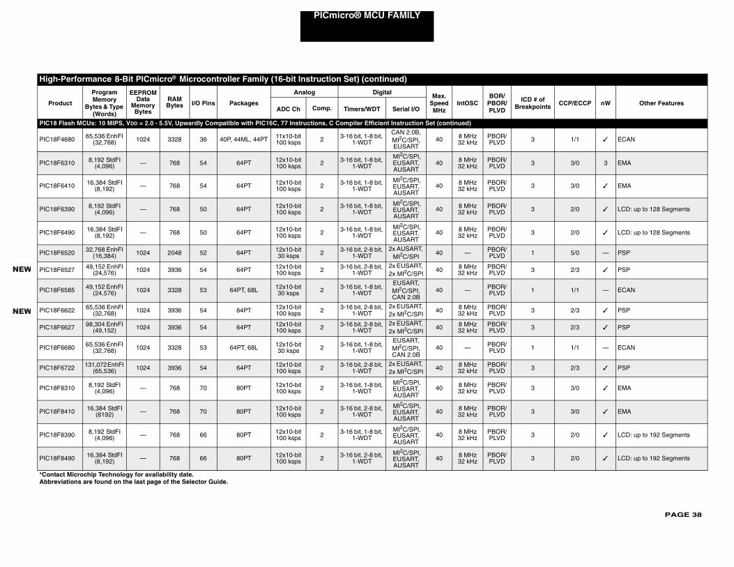
PAGE 38
PICmicro® MCU FAMILY
PIC18
PIC18F 3 1/1 ✓ ECAN
PIC18F 3 3/0 3 EMA
PIC18F 3 3/0 ✓ EMA
PIC18F 3 2/0 ✓ LCD: up to 128 Segments
PIC18F 3 2/0 ✓ LCD: up to 128 Segments
PIC18F 1 5/0 — PSP
PIC18F 3 2/3 ✓ PSP
PIC18F 1 1/1 — ECAN
PIC18F 3 2/3 ✓ PSP
PIC18F 3 2/3 ✓ PSP
PIC18F 1 1/1 — ECAN
PIC18F 3 2/3 ✓ PSP
PIC18F 3 3/0 ✓ EMA
PIC18F 3 3/0 ✓ EMA
PIC18F 3 2/0 ✓ LCD: up to 192 Segments
PIC18F 3 2/0 ✓ LCD: up to 192 Segments
High-
Pro ICD # of Breakpoints CCP/ECCP nW Other Features
*ContaAbbrev
NEW
NEW
Flash MCUs: 10 MIPS, VDD = 2.0 - 5.5V, Upwardly Compatible with PIC16C, 77 Instructions, C Compiler Efficient Instruction Set (continued)
4680 65,536 EnhFI (32,768) 1024 3328 36 40P, 44ML, 44PT 11x10-bit
100 ksps 2 3-16 bit, 1-8 bit, 1-WDT
CAN 2.0B, MI2C/SPI, EUSART
40 8 MHz32 kHz
PBOR/PLVD
6310 8,192 StdFI (4,096) — 768 54 64PT 12x10-bit
100 ksps 2 3-16 bit, 1-8 bit, 1-WDT
MI2C/SPI, EUSART, AUSART
40 8 MHz32 kHz
PBOR/PLVD
6410 16,384 StdFI (8,192) — 768 54 64PT 12x10-bit
100 ksps 2 3-16 bit, 1-8 bit, 1-WDT
MI2C/SPI, EUSART, AUSART
40 8 MHz32 kHz
PBOR/PLVD
6390 8,192 StdFI (4,096) — 768 50 64PT 12x10-bit
100 ksps 2 3-16 bit, 1-8 bit, 1-WDT
MI2C/SPI, EUSART, AUSART
40 8 MHz32 kHz
PBOR/PLVD
6490 16,384 StdFI (8,192) — 768 50 64PT 12x10-bit
100 ksps 2 3-16 bit, 1-8 bit, 1-WDT
MI2C/SPI, EUSART, AUSART
40 8 MHz32 kHz
PBOR/PLVD
6520 32,768 EnhFI (16,384) 1024 2048 52 64PT 12x10-bit
30 ksps 2 3-16 bit, 2-8 bit, 1-WDT
2x AUSART, MI2C/SPI
40 — PBOR/PLVD
6527 49,152 EnhFl (24,576) 1024 3936 54 64PT 12x10-bit
100 ksps 2 3-16 bit, 2-8 bit, 1-WDT
2x EUSART, 2x MI2C/SPI
40 8 MHz32 kHz
PBOR/PLVD
6585 49,152 EnhFI (24,576) 1024 3328 53 64PT, 68L 12x10-bit
30 ksps 2 3-16 bit, 1-8 bit, 1-WDT
EUSART, MI2C/SPI, CAN 2.0B
40 — PBOR/PLVD
6622 65,536 EnhFl (32,768) 1024 3936 54 64PT 12x10-bit
100 ksps 2 3-16 bit, 2-8 bit, 1-WDT
2x EUSART, 2x MI2C/SPI
40 8 MHz32 kHz
PBOR/PLVD
6627 98,304 EnhFI (49,152) 1024 3936 54 64PT 12x10-bit
100 ksps 2 3-16 bit, 2-8 bit, 1-WDT
2x EUSART, 2x MI2C/SPI
40 8 MHz32 kHz
PBOR/PLVD
6680 65,536 EnhFI (32,768) 1024 3328 53 64PT, 68L 12x10-bit
30 ksps 2 3-16 bit, 1-8 bit, 1-WDT
EUSART, MI2C/SPI, CAN 2.0B
40 — PBOR/PLVD
6722 131,072 EnhFI (65,536) 1024 3936 54 64PT 12x10-bit
100 ksps 2 3-16 bit, 2-8 bit, 1-WDT
2x EUSART, 2x MI2C/SPI
40 8 MHz32 kHz
PBOR/PLVD
8310 8,192 StdFI (4,096) — 768 70 80PT 12x10-bit
100 ksps 2 3-16 bit, 1-8 bit, 1-WDT
MI2C/SPI, EUSART, AUSART
40 8 MHz32 kHz
PBOR/PLVD
8410 16,384 StdFI (8192) — 768 70 80PT 12x10-bit
100 ksps 2 3-16 bit, 2-8 bit, 1-WDT
MI2C/SPI, EUSART, AUSART
40 8 MHz32 kHz
PBOR/PLVD
8390 8,192 StdFI (4,096) — 768 66 80PT 12x10-bit
100 ksps 2 3-16 bit, 1-8 bit, 1-WDT
MI2C/SPI, EUSART, AUSART
40 8 MHz32 kHz
PBOR/PLVD
8490 16,384 StdFI (8,192) — 768 66 80PT 12x10-bit
100 ksps 2 3-16 bit, 2-8 bit, 1-WDT
MI2C/SPI, EUSART, AUSART
40 8 MHz32 kHz
PBOR/PLVD
Performance 8-Bit PICmicro® Microcontroller Family (16-bit Instruction Set) (continued)
duct
Program Memory
Bytes & Type (Words)
EEPROM Data
Memory Bytes
RAM Bytes I/O Pins Packages
Analog Digital Max. Speed MHz
IntOSCBOR/
PBOR/PLVDADC Ch Comp. Timers/WDT Serial I/O
ct Microchip Technology for availability date.iations are found on the last page of the Selector Guide.
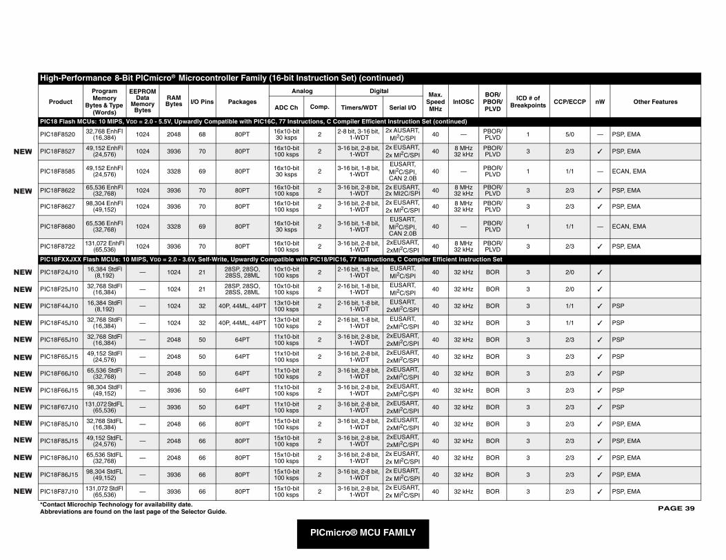
PAGE 39
PIC18
PIC18F 5/0 — PSP, EMA
PIC18F 2/3 ✓ PSP, EMA
PIC18F 1/1 — ECAN, EMA
PIC18F 2/3 ✓ PSP, EMA
PIC18F 2/3 ✓ PSP, EMA
PIC18F 1/1 — ECAN, EMA
PIC18F 2/3 ✓ PSP, EMA
PIC18F
PIC18F 2/0 ✓
PIC18F 2/0 ✓
PIC18F 1/1 ✓ PSP
PIC18F 1/1 ✓ PSP
PIC18F 2/3 ✓ PSP
PIC18F 2/3 ✓ PSP
PIC18F 2/3 ✓ PSP
PIC18F 2/3 ✓ PSP
PIC18F 2/3 ✓ PSP
PIC18F 2/3 ✓ PSP, EMA
PIC18F 2/3 ✓ PSP, EMA
PIC18F 2/3 ✓ PSP, EMA
PIC18F 2/3 ✓ PSP, EMA
PIC18F 2/3 ✓ PSP, EMA
High
Pro # of oints CCP/ECCP nW Other Features
*ContaAbbre
NEW
NEW
NEW
NEW
NEW
NEW
NEW
NEW
NEW
NEW
NEW
NEW
NEW
NEW
NEW
NEW
PICmicro® MCU FAMILY
Flash MCUs: 10 MIPS, VDD = 2.0 - 5.5V, Upwardly Compatible with PIC16C, 77 Instructions, C Compiler Efficient Instruction Set (continued)
8520 32,768 EnhFI (16,384) 1024 2048 68 80PT 16x10-bit
30 ksps 2 2-8 bit, 3-16 bit, 1-WDT
2x AUSART, MI2C/SPI
40 — PBOR/PLVD 1
8527 49,152 EnhFl (24,576) 1024 3936 70 80PT 16x10-bit
100 ksps 2 3-16 bit, 2-8 bit, 1-WDT
2x EUSART, 2x MI2C/SPI
40 8 MHz32 kHz
PBOR/PLVD 3
8585 49,152 EnhFI (24,576) 1024 3328 69 80PT 16x10-bit
30 ksps 2 3-16 bit, 1-8 bit, 1-WDT
EUSART, MI2C/SPI, CAN 2.0B
40 — PBOR/PLVD 1
8622 65,536 EnhFl (32,768) 1024 3936 70 80PT 16x10-bit
100 ksps 2 3-16 bit, 2-8 bit, 1-WDT
2x EUSART, 2x MI2C/SPI 40 8 MHz
32 kHzPBOR/PLVD 3
8627 98,304 EnhFI (49,152) 1024 3936 70 80PT 16x10-bit
100 ksps 2 3-16 bit, 2-8 bit, 1-WDT
2x EUSART, 2x MI2C/SPI
40 8 MHz32 kHz
PBOR/PLVD 3
8680 65,536 EnhFI (32,768) 1024 3328 69 80PT 16x10-bit
30 ksps 2 3-16 bit, 1-8 bit, 1-WDT
EUSART, MI2C/SPI, CAN 2.0B
40 — PBOR/PLVD 1
8722 131,072 EnhFI(65,536) 1024 3936 70 80PT 16x10-bit
100 ksps 2 3-16 bit, 2-8 bit, 1-WDT
2xEUSART, 2xMI2C/SPI
40 8 MHz32 kHz
PBOR/PLVD 3
XXJXX Flash MCUs: 10 MIPS, VDD = 2.0 - 3.6V, Self-Write, Upwardly Compatible with PIC18/PIC16, 77 Instructions, C Compiler Efficient Instruction Set
24J10 16,384 StdFl(8,192) — 1024 21 28SP, 28SO,
28SS, 28ML10x10-bit100 ksps 2 2-16 bit, 1-8 bit,
1-WDTEUSART, MI2C/SPI
40 32 kHz BOR 3
25J10 32,768 StdFl(16,384) — 1024 21 28SP, 28SO,
28SS, 28ML10x10-bit100 ksps 2 2-16 bit, 1-8 bit,
1-WDTEUSART, MI2C/SPI
40 32 kHz BOR 3
44J10 16,384 StdFl(8,192) — 1024 32 40P, 44ML, 44PT 13x10-bit
100 ksps 2 2-16 bit, 1-8 bit, 1-WDT
EUSART, 2xMI2C/SPI
40 32 kHz BOR 3
45J10 32,768 StdFl(16,384) — 1024 32 40P, 44ML, 44PT 13x10-bit
100 ksps 2 2-16 bit, 1-8 bit, 1-WDT
EUSART, 2xMI2C/SPI
40 32 kHz BOR 3
65J10 32,768 StdFl(16,384) — 2048 50 64PT 11x10-bit
100 ksps 2 3-16 bit, 2-8 bit, 1-WDT
2xEUSART, 2xMI2C/SPI
40 32 kHz BOR 3
65J15 49,152 StdFl(24,576) — 2048 50 64PT 11x10-bit
100 ksps 2 3-16 bit, 2-8 bit, 1-WDT
2xEUSART, 2xMI2C/SPI
40 32 kHz BOR 3
66J10 65,536 StdFl(32,768) — 2048 50 64PT 11x10-bit
100 ksps 2 3-16 bit, 2-8 bit, 1-WDT
2xEUSART, 2xMI2C/SPI
40 32 kHz BOR 3
66J15 98,304 StdFl (49,152) — 3936 50 64PT 11x10-bit
100 ksps 2 3-16 bit, 2-8 bit, 1-WDT
2xEUSART, 2xMI2C/SPI
40 32 kHz BOR 3
67J10 131,072 StdFL (65,536) — 3936 50 64PT 11x10-bit
100 ksps 2 3-16 bit, 2-8 bit, 1-WDT
2xEUSART, 2xMI2C/SPI
40 32 kHz BOR 3
85J10 32,768 StdFL (16,384) — 2048 66 80PT 15x10-bit
100 ksps 2 3-16 bit, 2-8 bit, 1-WDT
2xEUSART, 2xMI2C/SPI
40 32 kHz BOR 3
85J15 49,152 StdFL (24,576) — 2048 66 80PT 15x10-bit
100 ksps 2 3-16 bit, 2-8 bit, 1-WDT
2xEUSART, 2xMI2C/SPI
40 32 kHz BOR 3
86J10 65,536 StdFL (32,768) — 2048 66 80PT 15x10-bit
100 ksps 2 3-16 bit, 2-8 bit, 1-WDT
2x EUSART, 2x MI2C/SPI
40 32 kHz BOR 3
86J15 98,304 StdFL (49,152) — 3936 66 80PT 15x10-bit
100 ksps 2 3-16 bit, 2-8 bit, 1-WDT
2x EUSART, 2x MI2C/SPI
40 32 kHz BOR 3
87J10 131,072 StdFl (65,536) — 3936 66 80PT 15x10-bit
100 ksps 2 3-16 bit, 2-8 bit, 1-WDT
2x EUSART, 2x MI2C/SPI
40 32 kHz BOR 3
-Performance 8-Bit PICmicro® Microcontroller Family (16-bit Instruction Set) (continued)
duct
Program Memory
Bytes & Type (Words)
EEPROM Data
Memory Bytes
RAM Bytes I/O Pins Packages
Analog Digital Max. Speed MHz
IntOSCBOR/
PBOR/PLVD
ICD BreakpADC Ch Comp. Timers/WDT Serial I/O
ct Microchip Technology for availability date.viations are found on the last page of the Selector Guide.
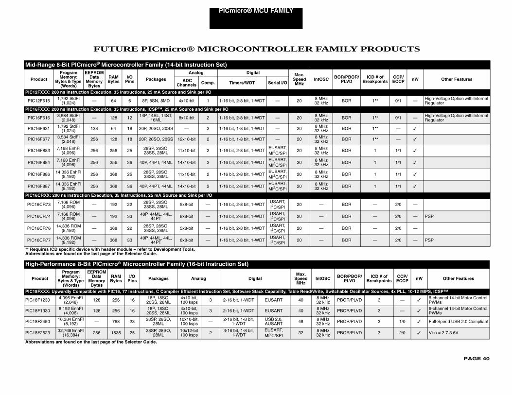
PAGE 40
PICmicro® MCU FAMILY
PRODUCTS
Mid-R
Produ R/ ICD # of Breakpoints
CCP/ECCP nW Other Features
PIC12FX
PIC12F 1** 0/1 — High-Voltage Option with Internal Regulator
PIC16FX
PIC16F 1** 0/1 — High-Voltage Option with Internal Regulator
PIC16F 1** — ✓
PIC16F 1** — ✓
PIC16F 1 1/1 ✓
PIC16F 1 1/1 ✓
PIC16F 1 1/1 ✓
PIC16F 1 1/1 ✓
PIC16CR
PIC16C — 2/0 —
PIC16C — 2/0 — PSP
PIC16C — 2/0 —
PIC16C — 2/0 — PSP
** RequAbbrevi
High-P
Prod R/ ICD # of Breakpoints
CCP/ECCP nW Other Features
PIC18FX cillator Sources, 4x PLL, 10-12 MIPS, ICSP™
PIC18F1 VD 3 — ✓6-channel 14-bit Motor Control PWMs
PIC18F1 VD 3 — ✓6-channel 14-bit Motor Control PWMs
PIC18F2 VD 3 1/0 ✓ Full-Speed USB 2.0 Compliant
PIC18F2 VD 3 2/0 ✓ VDD = 2.7-3.6V
Abbrevi
FUTURE PICmicro® MICROCONTROLLER FAMILY
ange 8-Bit PICmicro® Microcontroller Family (14-bit Instruction Set)
ct
Program Memory:
Bytes & Type (Words)
EEPROM Data
Memory Bytes
RAM Bytes
I/O Pins Packages
Analog Digital Max. Speed MHz
IntOSC BOR/PBOPLVD ADC
Channels Comp. Timers/WDT Serial I/O
XX: 200 ns Instruction Execution, 35 Instructions, 25 mA Source and Sink per I/O
615 1,792 StdFI (1,024) — 64 6 8P, 8SN, 8MD 4x10-bit 1 1-16 bit, 2-8 bit, 1-WDT — 20 8 MHz
32 kHz BOR
XX: 200 ns Instruction Execution, 35 Instructions, ICSP™, 25 mA Source and Sink per I/O
616 3,584 StdFI (2,048) — 128 12 14P, 14SL, 14ST,
16ML 8x10-bit 2 1-16 bit, 2-8 bit, 1-WDT — 20 8 MHz32 kHz BOR
631 1,792 StdFI (1,024) 128 64 18 20P, 20SO, 20SS — 2 1-16 bit, 1-8 bit, 1-WDT — 20 8 MHz
32 kHz BOR
677 3,584 StdFI (2,048) 256 128 18 20P, 20SO, 20SS 12x10-bit 2 1-16 bit, 1-8 bit, 1-WDT — 20 8 MHz
32 kHz BOR
883 7,168 EnhFl (4,096) 256 256 25 28SP, 28SO,
28SS, 28ML 11x10-bit 2 1-16 bit, 2-8 bit, 1-WDTEUSART, MI2C/SPI
20 8 MHz32 kHz BOR
884 7,168 EnhFl (4,096) 256 256 36 40P, 44PT, 44ML 14x10-bit 2 1-16 bit, 2-8 bit, 1-WDT
EUSART, MI2C/SPI
20 8 MHz32 kHz BOR
886 14,336 EnhFl (8,192) 256 368 25 28SP, 28SO,
28SS, 28ML 11x10-bit 2 1-16 bit, 2-8 bit, 1-WDTEUSART, MI2C/SPI
20 8 MHz32 kHz BOR
887 14,336 EnhFl (8,192) 256 368 36 40P, 44PT, 44ML 14x10-bit 2 1-16 bit, 2-8 bit, 1-WDT
EUSART, MI2C/SPI
20 8 MHz32 kHz BOR
XX: 200 ns Instruction Execution, 35 Instructions, 25 mA Source and Sink per I/O
R73 7,168 ROM (4,096) — 192 22 28SP, 28SO,
28SS, 28ML 5x8-bit — 1-16 bit, 2-8 bit, 1-WDTUSART, I2C/SPI
20 — BOR
R74 7,168 ROM (4,096) — 192 33 40P, 44ML, 44L,
44PT 8x8-bit — 1-16 bit, 2-8 bit, 1-WDTUSART, I2C/SPI
20 — BOR
R76 14,336 ROM (8,192) — 368 22 28SP, 28SO,
28SS, 28ML 5x8-bit — 1-16 bit, 2-8 bit, 1-WDTUSART, I2C/SPI
20 — BOR
R77 14,336 ROM (8,192) — 368 33 40P, 44ML, 44L,
44PT 8x8-bit — 1-16 bit, 2-8 bit, 1-WDTUSART, I2C/SPI
20 — BOR
ires ICD specific device with header module – refer to Development Tools.ations are found on the last page of the Selector Guide.
erformance 8-Bit PICmicro® Microcontroller Family (16-bit Instruction Set)
uct
Program Memory:
Bytes & Type (Words)
EEPROM Data
Memory Bytes
RAM Bytes
I/O Pins Packages Analog Digital
Max. Speed MHz
IntOSC BOR/PBOPLVD
XX: Upwardly Compatible with PIC16, 77 Instructions, C Compiler Efficient Instruction Set, Software Stack Capability, Table Read/Write, Switchable Os
230 4,096 EnhFI (2,048) 128 256 16 18P, 18SO,
20SS, 28ML4x10-bit, 100 ksps 3 2-16 bit, 1-WDT EUSART 40 8 MHz
32 kHz PBOR/PL
330 8,192 EnhFI (4,096) 128 256 16 18P, 18SO,
20SS, 28ML4x10-bit, 100 ksps 3 2-16 bit, 1-WDT EUSART 40 8 MHz
32 kHz PBOR/PL
450 16,384 EnhFI (8,192) — 768 23 28SP, 28SO,
28ML10x10-bit, 100 ksps — 2-16 bit, 1-8 bit,
1-WDTUSB 2.0,AUSART 48 8 MHz
32 kHz PBOR/PL
523 32,768 EnhFl (16,384) 256 1536 25 28SP, 28SO,
28ML10x12-bit 100 ksps 2 3-16 bit, 1-8 bit,
1-WDTEUSART, MI2C/SPI
32 8 MHz 32 kHz PBOR/PL
ations are found on the last page of the Selector Guide.
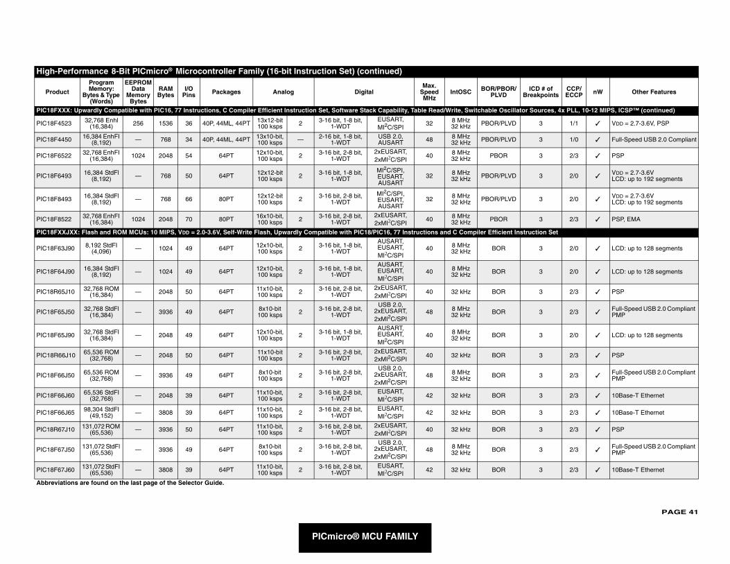
PAGE 41
PIC18FX cillator Sources, 4x PLL, 10-12 MIPS, ICSP™ (continued)
PIC18F4 VD 3 1/1 ✓ VDD = 2.7-3.6V, PSP
PIC18F4 VD 3 1/0 ✓ Full-Speed USB 2.0 Compliant
PIC18F6 3 2/3 ✓ PSP
PIC18F6 VD 3 2/0 ✓VDD = 2.7-3.6VLCD: up to 192 segments
PIC18F8 VD 3 2/0 ✓VDD = 2.7-3.6VLCD: up to 192 segments
PIC18F8 3 2/3 ✓ PSP, EMA
PIC18FX nt Instruction Set
PIC18F6 3 2/0 ✓ LCD: up to 128 segments
PIC18F6 3 2/0 ✓ LCD: up to 128 segments
PIC18R6 3 2/3 ✓ PSP
PIC18F6 3 2/3 ✓Full-Speed USB 2.0 Compliant PMP
PIC18F6 3 2/0 ✓ LCD: up to 128 segments
PIC18R 3 2/3 ✓ PSP
PIC18F6 3 2/3 ✓Full-Speed USB 2.0 Compliant PMP
PIC18F6 3 2/3 ✓ 10Base-T Ethernet
PIC18F6 3 2/3 ✓ 10Base-T Ethernet
PIC18R6 3 2/3 ✓ PSP
PIC18F6 3 2/3 ✓Full-Speed USB 2.0 Compliant PMP
PIC18F6 3 2/3 ✓ 10Base-T Ethernet
High-P
Prod R/ ICD # of Breakpoints
CCP/ECCP nW Other Features
Abbrevi
PICmicro® MCU FAMILY
XX: Upwardly Compatible with PIC16, 77 Instructions, C Compiler Efficient Instruction Set, Software Stack Capability, Table Read/Write, Switchable Os
523 32,768 Enhl (16,384) 256 1536 36 40P, 44ML, 44PT 13x12-bit
100 ksps 2 3-16 bit, 1-8 bit, 1-WDT
EUSART, MI2C/SPI
32 8 MHz 32 kHz PBOR/PL
450 16,384 EnhFI (8,192) — 768 34 40P, 44ML, 44PT 13x10-bit,
100 ksps — 2-16 bit, 1-8 bit, 1-WDT
USB 2.0,AUSART 48 8 MHz
32 kHz PBOR/PL
522 32,768 EnhFI (16,384) 1024 2048 54 64PT 12x10-bit,
100 ksps 2 3-16 bit, 2-8 bit, 1-WDT
2xEUSART, 2xMI2C/SPI
40 8 MHz32 kHz PBOR
493 16,384 StdFl (8,192) — 768 50 64PT 12x12-bit
100 ksps 2 3-16 bit, 1-8 bit, 1-WDT
MI2C/SPI, EUSART, AUSART
32 8 MHz 32 kHz PBOR/PL
493 16,384 StdFl (8,192) — 768 66 80PT 12x12-bit
100 ksps 2 3-16 bit, 2-8 bit, 1-WDT
MI2C/SPI, EUSART, AUSART
32 8 MHz 32 kHz PBOR/PL
522 32,768 EnhFI (16,384) 1024 2048 70 80PT 16x10-bit,
100 ksps 2 3-16 bit, 2-8 bit, 1-WDT
2xEUSART, 2xMI2C/SPI
40 8 MHz32 kHz PBOR
XJXX: Flash and ROM MCUs: 10 MIPS, VDD = 2.0-3.6V, Self-Write Flash, Upwardly Compatible with PIC18/PIC16, 77 Instructions and C Compiler Efficie
3J90 8,192 StdFI (4,096) — 1024 49 64PT 12x10-bit,
100 ksps 2 3-16 bit, 1-8 bit, 1-WDT
AUSART, EUSART, MI2C/SPI
40 8 MHz 32 kHz BOR
4J90 16,384 StdFI (8,192) — 1024 49 64PT 12x10-bit,
100 ksps 2 3-16 bit, 1-8 bit, 1-WDT
AUSART, EUSART, MI2C/SPI
40 8 MHz32 kHz BOR
5J10 32,768 ROM (16,384) — 2048 50 64PT 11x10-bit,
100 ksps 2 3-16 bit, 2-8 bit, 1-WDT
2xEUSART, 2xMI2C/SPI
40 32 kHz BOR
5J50 32,768 StdFl (16,384) — 3936 49 64PT 8x10-bit
100 ksps 2 3-16 bit, 2-8 bit, 1-WDT
USB 2.0, 2xEUSART, 2xMI2C/SPI
48 8 MHz 32 kHz BOR
5J90 32,768 StdFI (16,384) — 2048 49 64PT 12x10-bit,
100 ksps 2 3-16 bit, 1-8 bit, 1-WDT
AUSART, EUSART, MI2C/SPI
40 8 MHz32 kHz BOR
66J10 65,536 ROM (32,768) — 2048 50 64PT 11x10-bit
100 ksps 2 3-16 bit, 2-8 bit, 1-WDT
2xEUSART, 2xMI2C/SPI
40 32 kHz BOR
6J50 65,536 ROM (32,768) — 3936 49 64PT 8x10-bit
100 ksps 2 3-16 bit, 2-8 bit, 1-WDT
USB 2.0, 2xEUSART, 2xMI2C/SPI
48 8 MHz 32 kHz BOR
6J60 65,536 StdFI (32,768) — 2048 39 64PT 11x10-bit,
100 ksps 2 3-16 bit, 2-8 bit, 1-WDT
EUSART, MI2C/SPI
42 32 kHz BOR
6J65 98,304 StdFI (49,152) — 3808 39 64PT 11x10-bit,
100 ksps 2 3-16 bit, 2-8 bit, 1-WDT
EUSART, MI2C/SPI
42 32 kHz BOR
7J10 131,072 ROM (65,536) — 3936 50 64PT 11x10-bit,
100 ksps 2 3-16 bit, 2-8 bit, 1-WDT
2xEUSART, 2xMI2C/SPI
40 32 kHz BOR
7J50 131,072 StdFl (65,536) — 3936 49 64PT 8x10-bit
100 ksps 2 3-16 bit, 2-8 bit, 1-WDT
USB 2.0, 2xEUSART, 2xMI2C/SPI
48 8 MHz 32 kHz BOR
7J60 131,072 StdFI (65,536) — 3808 39 64PT 11x10-bit,
100 ksps 2 3-16 bit, 2-8 bit, 1-WDT
EUSART, MI2C/SPI
42 32 kHz BOR
erformance 8-Bit PICmicro® Microcontroller Family (16-bit Instruction Set) (continued)
uct
Program Memory:
Bytes & Type (Words)
EEPROM Data
Memory Bytes
RAM Bytes
I/O Pins Packages Analog Digital
Max. Speed MHz
IntOSC BOR/PBOPLVD
ations are found on the last page of the Selector Guide.
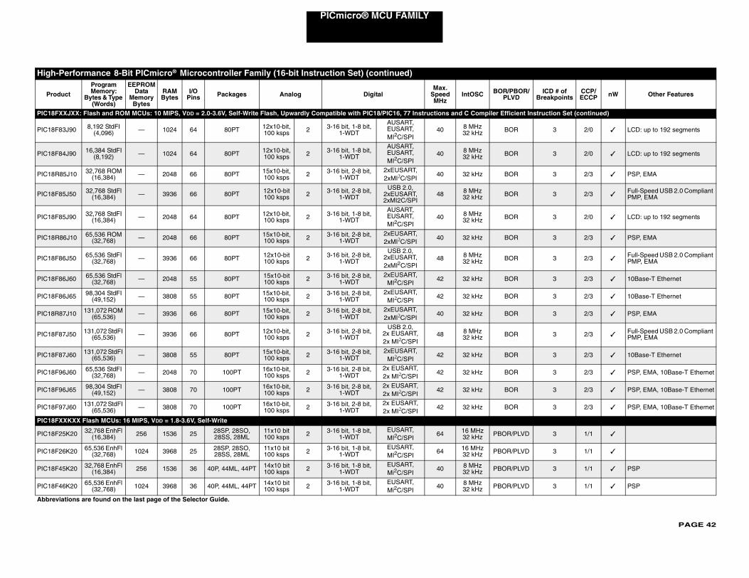
PAGE 42
PICmicro® MCU FAMILY
PIC18FX nt Instruction Set (continued)
PIC18F8 3 2/0 ✓ LCD: up to 192 segments
PIC18F8 3 2/0 ✓ LCD: up to 192 segments
PIC18R8 3 2/3 ✓ PSP, EMA
PIC18F8 3 2/3 ✓Full-Speed USB 2.0 Compliant PMP, EMA
PIC18F8 3 2/0 ✓ LCD: up to 192 segments
PIC18R8 3 2/3 ✓ PSP, EMA
PIC18F8 3 2/3 ✓Full-Speed USB 2.0 Compliant PMP, EMA
PIC18F8 3 2/3 ✓ 10Base-T Ethernet
PIC18F8 3 2/3 ✓ 10Base-T Ethernet
PIC18R8 3 2/3 ✓ PSP, EMA
PIC18F8 3 2/3 ✓Full-Speed USB 2.0 Compliant PMP, EMA
PIC18F8 3 2/3 ✓ 10Base-T Ethernet
PIC18F9 3 2/3 ✓ PSP, EMA, 10Base-T Ethernet
PIC18F9 3 2/3 ✓ PSP, EMA, 10Base-T Ethernet
PIC18F9 3 2/3 ✓ PSP, EMA, 10Base-T Ethernet
PIC18FX
PIC18F2 VD 3 1/1 ✓
PIC18F2 VD 3 1/1 ✓
PIC18F4 VD 3 1/1 ✓ PSP
PIC18F4 VD 3 1/1 ✓ PSP
High-P
Prod R/ ICD # of Breakpoints
CCP/ECCP nW Other Features
Abbrevi
XJXX: Flash and ROM MCUs: 10 MIPS, VDD = 2.0-3.6V, Self-Write Flash, Upwardly Compatible with PIC18/PIC16, 77 Instructions and C Compiler Efficie
3J90 8,192 StdFI (4,096) — 1024 64 80PT 12x10-bit,
100 ksps 2 3-16 bit, 1-8 bit, 1-WDT
AUSART, EUSART, MI2C/SPI
40 8 MHz32 kHz BOR
4J90 16,384 StdFI (8,192) — 1024 64 80PT 12x10-bit,
100 ksps 2 3-16 bit, 1-8 bit, 1-WDT
AUSART, EUSART, MI2C/SPI
40 8 MHz32 kHz BOR
5J10 32,768 ROM (16,384) — 2048 66 80PT 15x10-bit,
100 ksps 2 3-16 bit, 2-8 bit, 1-WDT
2xEUSART, 2xMI2C/SPI
40 32 kHz BOR
5J50 32,768 StdFl (16,384) — 3936 66 80PT 12x10-bit
100 ksps 2 3-16 bit, 2-8 bit, 1-WDT
USB 2.0, 2xEUSART, 2xMI2C/SPI
48 8 MHz 32 kHz BOR
5J90 32,768 StdFI (16,384) — 2048 64 80PT 12x10-bit,
100 ksps 2 3-16 bit, 1-8 bit, 1-WDT
AUSART, EUSART, MI2C/SPI
40 8 MHz32 kHz BOR
6J10 65,536 ROM (32,768) — 2048 66 80PT 15x10-bit,
100 ksps 2 3-16 bit, 2-8 bit, 1-WDT
2xEUSART, 2xMI2C/SPI
40 32 kHz BOR
6J50 65,536 StdFI (32,768) — 3936 66 80PT 12x10-bit
100 ksps 2 3-16 bit, 2-8 bit, 1-WDT
USB 2.0, 2xEUSART, 2xMI2C/SPI
48 8 MHz32 kHz BOR
6J60 65,536 StdFl (32,768) — 2048 55 80PT 15x10-bit
100 ksps 2 3-16 bit, 2-8 bit, 1-WDT
2xEUSART, MI2C/SPI
42 32 kHz BOR
6J65 98,304 StdFI (49,152) — 3808 55 80PT 15x10-bit,
100 ksps 2 3-16 bit, 2-8 bit, 1-WDT
2xEUSART, MI2C/SPI
42 32 kHz BOR
7J10 131,072 ROM (65,536) — 3936 66 80PT 15x10-bit,
100 ksps 2 3-16 bit, 2-8 bit, 1-WDT
2xEUSART, 2xMI2C/SPI
40 32 kHz BOR
7J50 131,072 StdFI (65,536) — 3936 66 80PT 12x10-bit,
100 ksps 2 3-16 bit, 2-8 bit, 1-WDT
USB 2.0,2x EUSART, 2x MI2C/SPI
48 8 MHz32 kHz BOR
7J60 131,072 StdFI (65,536) — 3808 55 80PT 15x10-bit,
100 ksps 2 3-16 bit, 2-8 bit, 1-WDT
2xEUSART, MI2C/SPI
42 32 kHz BOR
6J60 65,536 StdFI (32,768) — 2048 70 100PT 16x10-bit,
100 ksps 2 3-16 bit, 2-8 bit, 1-WDT
2x EUSART, 2x MI2C/SPI
42 32 kHz BOR
6J65 98,304 StdFI (49,152) — 3808 70 100PT 16x10-bit,
100 ksps 2 3-16 bit, 2-8 bit, 1-WDT
2x EUSART, 2x MI2C/SPI
42 32 kHz BOR
7J60 131,072 StdFI (65,536) — 3808 70 100PT 16x10-bit,
100 ksps 2 3-16 bit, 2-8 bit, 1-WDT
2x EUSART, 2x MI2C/SPI
42 32 kHz BOR
XKXX Flash MCUs: 16 MIPS, VDD = 1.8-3.6V, Self-Write
5K20 32,768 EnhFl (16,384) 256 1536 25 28SP, 28SO,
28SS, 28ML11x10 bit 100 ksps 2 3-16 bit, 1-8 bit,
1-WDTEUSART, MI2C/SPI
64 16 MHz 32 kHz PBOR/PL
6K20 65,536 EnhFl (32,768) 1024 3968 25 28SP, 28SO,
28SS, 28ML11x10 bit 100 ksps 2 3-16 bit, 1-8 bit,
1-WDTEUSART, MI2C/SPI
64 16 MHz 32 kHz PBOR/PL
5K20 32,768 EnhFl (16,384) 256 1536 36 40P, 44ML, 44PT 14x10 bit
100 ksps 2 3-16 bit, 1-8 bit, 1-WDT
EUSART, Mi2C/SPI
40 8 MHz 32 kHz PBOR/PL
6K20 65,536 EnhFl (32,768) 1024 3968 36 40P, 44ML, 44PT 14x10 bit
100 ksps 2 3-16 bit, 1-8 bit, 1-WDT
EUSART, Mi2C/SPI
40 8 MHz 32 kHz PBOR/PL
erformance 8-Bit PICmicro® Microcontroller Family (16-bit Instruction Set) (continued)
uct
Program Memory:
Bytes & Type (Words)
EEPROM Data
Memory Bytes
RAM Bytes
I/O Pins Packages Analog Digital
Max. Speed MHz
IntOSC BOR/PBOPLVD
ations are found on the last page of the Selector Guide.
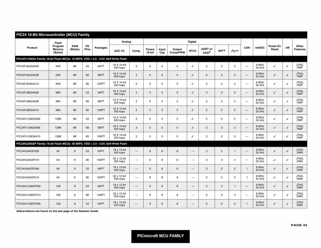
PAGE 43
PIC24
CAN IntOSC Power On Reset nW Other
FeaturesI2C™
PIC24F
PIC24F 2 — 8 MHz 32 kHz ✓ ✓
JTAG, PMP
PIC24F 2 — 8 MHz 32 kHz ✓ ✓
JTAG, PMP
PIC24F 2 — 8 MHz 32 kHz ✓ ✓
JTAG, PMP
PIC24F 2 — 8 MHz 32 kHz ✓ ✓
JTAG, PMP
PIC24F 2 — 8 MHz 32 kHz ✓ ✓
JTAG, PMP
PIC24F 2 — 8 MHz 32 kHz ✓ ✓
JTAG, PMP
PIC24F 2 — 8 MHz 32 kHz ✓ ✓
JTAG, PMP
PIC24F 2 — 8 MHz 32 kHz ✓ ✓
JTAG, PMP
PIC24F 2 — 8 MHz 32 kHz ✓ ✓
JTAG, PMP
PIC24H
PIC24H 1 — 8 MHz 32 kHz ✓ ✓
JTAG, DMA
PIC24H 2 — 8 MHz 32 kHz ✓ ✓
JTAG, DMA
PIC24H 2 1 8 MHz 32 kHz ✓ ✓
JTAG, DMA
PIC24H 2 1 8 MHz 32 kHz ✓ ✓
JTAG, DMA
PIC24H 1 — 8 MHz 32 kHz ✓ ✓
JTAG, DMA
PIC24H 2 — 8 MHz 32 kHz ✓ ✓
JTAG, DMA
PIC24H 2 1 8 MHz 32 kHz ✓ ✓
JTAG, DMA
Abbrev
PICmicro® MCU FAMILY
16-Bit Microcontroller (MCU) Family
Product
Flash Program Memory (Bytes)
RAM (Bytes)
I/O Pins Packages
Analog Digital
ADC Ch Comp. Timers 16-bit
Input Cap
Output Comp/PWM RTCC
UART w/IrDA® SPI™
J128GA Family 16-bit Flash MCUs: 16 MIPS, VDD = 2.0 - 3.6V, Self-Write Flash
J64GA006 64K 8K 53 64PT 16 X 10-bit 500 ksps 2 5 5 5 ✓ 2 2
J64GA008 64K 8K 69 80PT 16 X 10-bit 500 ksps 2 5 5 5 ✓ 2 2
J64GA010 64K 8K 85 100PT 16 X 10-bit 500 ksps 2 5 5 5 ✓ 2 2
J96GA006 96K 8K 53 64PT 16 X 10-bit 500 ksps 2 5 5 5 ✓ 2 2
J96GA008 96K 8K 69 80PT 16 X 10-bit 500 ksps 2 5 5 5 ✓ 2 2
J96GA010 96K 8K 85 100PT 16 X 10-bit 500 ksps 2 5 5 5 ✓ 2 2
J128GA006 128K 8K 53 64PT 16 X 10-bit 500 ksps 2 5 5 5 ✓ 2 2
J128GA008 128K 8K 69 80PT 16 X 10-bit 500 ksps 2 5 5 5 ✓ 2 2
J128GA010 128K 8K 85 100PT 16 X 10-bit 500 ksps 2 5 5 5 ✓ 2 2
J256GP Family 16-bit Flash MCUs: 40 MIPS, VDD = 3.0 - 3.6V, Self-Write Flash
J64GP206 64 8 53 64PT 18 x 12-bit 500 ksps — 9 8 8 — 2 2
J64GP210 64 8 85 100PT 32 x 12-bit 500 ksps — 9 8 8 — 2 2
J64GP506 64 8 53 64PT 18 x 12-bit 500 ksps — 9 8 8 — 2 2
J64GP510 64 8 85 100PT 32 x 12-bit 500 ksps — 9 8 8 — 2 2
J128GP206 128 8 53 64PT 18 x 12-bit 500 ksps — 9 8 8 — 2 2
J128GP210 128 8 85 100PT 32 x 12-bit 500 ksps — 9 8 8 — 2 2
J128GP506 128 8 53 64PT 18 x 12-bit 500 ksps — 9 8 8 — 2 2
iations are found on the last page of the Selector Guide.
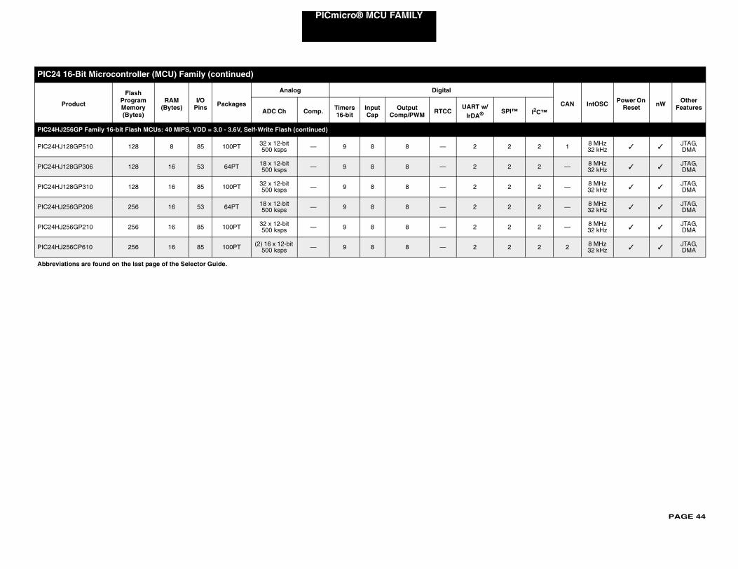
PAGE 44
PICmicro® MCU FAMILY
PIC24H
PIC24H 2 1 8 MHz 32 kHz ✓ ✓
JTAG, DMA
PIC24H 2 — 8 MHz 32 kHz ✓ ✓
JTAG, DMA
PIC24H 2 — 8 MHz 32 kHz ✓ ✓
JTAG, DMA
PIC24H 2 — 8 MHz 32 kHz ✓ ✓
JTAG, DMA
PIC24H 2 — 8 MHz 32 kHz ✓ ✓
JTAG, DMA
PIC24H 2 2 8 MHz 32 kHz ✓ ✓
JTAG, DMA
PIC24
CAN IntOSC Power On Reset nW Other
Features™ I2C™
Abbrev
J256GP Family 16-bit Flash MCUs: 40 MIPS, VDD = 3.0 - 3.6V, Self-Write Flash (continued)
J128GP510 128 8 85 100PT 32 x 12-bit 500 ksps — 9 8 8 — 2 2
J128GP306 128 16 53 64PT 18 x 12-bit 500 ksps — 9 8 8 — 2 2
J128GP310 128 16 85 100PT 32 x 12-bit 500 ksps — 9 8 8 — 2 2
J256GP206 256 16 53 64PT 18 x 12-bit 500 ksps — 9 8 8 — 2 2
J256GP210 256 16 85 100PT 32 x 12-bit 500 ksps — 9 8 8 — 2 2
J256CP610 256 16 85 100PT (2) 16 x 12-bit 500 ksps — 9 8 8 — 2 2
16-Bit Microcontroller (MCU) Family (continued)
Product
Flash Program Memory (Bytes)
RAM (Bytes)
I/O Pins Packages
Analog Digital
ADC Ch Comp. Timers 16-bit
Input Cap
Output Comp/PWM RTCC
UART w/IrDA® SPI
iations are found on the last page of the Selector Guide.
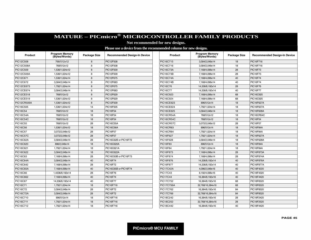
PAGE 45
PRODUCTS
PIC12C5
PIC12C5
PIC12C5
PIC12C5
PIC12C6
PIC12C6
PIC12CE
PIC12CE
PIC12CE
PIC12CE
PIC12CR
PIC16C5
PIC16C5
PIC16C5
PIC16C5
PIC16C5
PIC16C5
PIC16C5
PIC16C5
PIC16C6
PIC16C6
PIC16C6
PIC16C6
PIC16C6
PIC16C6
PIC16C6
PIC16C6
PIC16C6
PIC16C6
PIC16C6
PIC16C7
PIC16C7
PIC16C7
PIC16C7
PIC16C7
PIC16C7
18 PIC16F716
18 PIC16F716
28 PIC16F73
28 PIC16F73
40 PIC16F74
40 PIC16F74
28 PIC16F76
40 PIC16F77
68 PIC16C925
68 PIC16C925
18 PIC16F627A
18 PIC16F627A
18 PIC16F628A
18 PIC16CR54C
18 PIC16F54
28 PIC16F57
18 PIC16F84A
18 PIC16F84A
18 PIC16F627A
18 PIC16F628A
18 PIC16F84A
18 PIC16F84A
28 PIC16F873A
28 PIC16F874A
40 PIC16F876A
40 PIC16F877A
40 PIC18F4220
40 PIC18F4320
40 PIC18F4420
68 PIC18F6520
68 PIC18F6520
84 PIC18F8520
84 PIC18F8520
28 PIC18F2420
28 PIC18F2520
40 PIC18F4420
ry Package Size Recommended Design-In Device
PICmicro® MCU FAMILY
MATURE – PICmicro® MICROCONTROLLER FAMILYNot recommended for new designs.
Please use a device from the recommended column for new designs.
Product Program Memory (Bytes/Words) Package Size Recommended Design-In Device
08 768/512x12 8 PIC12F508
08A 768/512x12 8 PIC12F508
09 1,536/1,024x12 8 PIC12F509
09A 1,536/1,024x12 8 PIC12F509
71 1,536/1,024x14 8 PIC12F675
72 3,584/2,048x14 8 PIC12F683
673 1,792/1,024x14 8 PIC12F675
674 3,584/2,048x14 8 PIC12F683
518 768/512x12 8 PIC12F629
519 1,536/1,024x12 8 PIC12F629
509A 1,536/1,024x12 8 PIC12F509
05 1,536/1,024x12 14 PIC16F505
4 768/512x12 18 PIC16F54
4A 768/512x12 18 PIC16F54
4C 768/512x12 18 PIC16F54
5 768/512x12 28 PIC16C55A
6 1,536/1,024x12 18 PIC16C56A
7 3,072/2,048x12 28 PIC16F57
7C 3,072/2,048x12 28 PIC16F57
2A 3,584/2,048x14 28 PIC16C62B or PIC16F72
20 896/2,048x14 18 PIC16C620A
21 1,792/1,024x14 18 PIC16C621A
22 3,584/2,048x14 18 PIC16C622A
3 7,168/4,096x14 28 PIC16C63B or PIC16F73
4A 3,584/2,048x14 40 PIC16F74
42 7,168/4,096x14 28 PIC16F72
5A 7,168/4,096x14 40 PIC16C65B or PIC16F74
6 1,4336/8,192x14 28 PIC16F76
62 7,168/4,096x14 40 PIC16F74
7 14,336/8,192x14 40 PIC16F77
1 1,792/1,024x14 18 PIC16F716
2 3,584/2,048x14 28 PIC16F72
2A 3,584/2,048x14 28 PIC16F72
10 896/512x14 18 PIC16F716
11 1,792/1,024x14 18 PIC16F716
12 1,792/1,024x14 18 PIC16F716
PIC16C715 3,584/2,048x14
PIC16C716 3,584/2,048x14
PIC16C73A 7,168/4,096x14
PIC16C73B 7,168/4,096x14
PIC16C74A 7,168/4,096x14
PIC16C74B 7,168/4,096x14
PIC16C76 14,336/8,192x14
PIC16C77 14,336/8,192x14
PIC16C923 7,168/4,096x14
PIC16C924 7,168/4,096x14
PIC16CE623 896/512x14
PIC16CE624 1,792/1,024x14
PIC16CE625 3,584/2,048x14
PIC16CR54A 768/512x12
PIC16CR54C 768/512x12
PIC16CR57C 3,072/2,048x12
PIC16CR83 896/512x14
PIC16CR84 1,792/1,024x14
PIC16F627 1,792/1,024x14
PIC16F628 3,584/2,048x14
PIC16F83 896/512x14
PIC16F84 1,792/1,024x14
PIC16F873 7,168/4,096x14
PIC16F874 7,168/4,096x14
PIC16F876 14,336/8,192x14
PIC16F877 14,336/8,192x14
PIC17C42A 4,096/2,048x16
PIC17C43 8,192/4,096x16
PIC17C44 16,384/8,192x16
PIC17C752 16,384/8,192x16
PIC17C756A 32,768/16,384x16
PIC17C762 16,384/8,192x16
PIC17C766 32,768/16,384x16
PIC18C242 16,384/8,192x16
PIC18C252 32,768/16,384x16
PIC18C442 16,384/8,192x16
Product Program Memo(Bytes/Words)
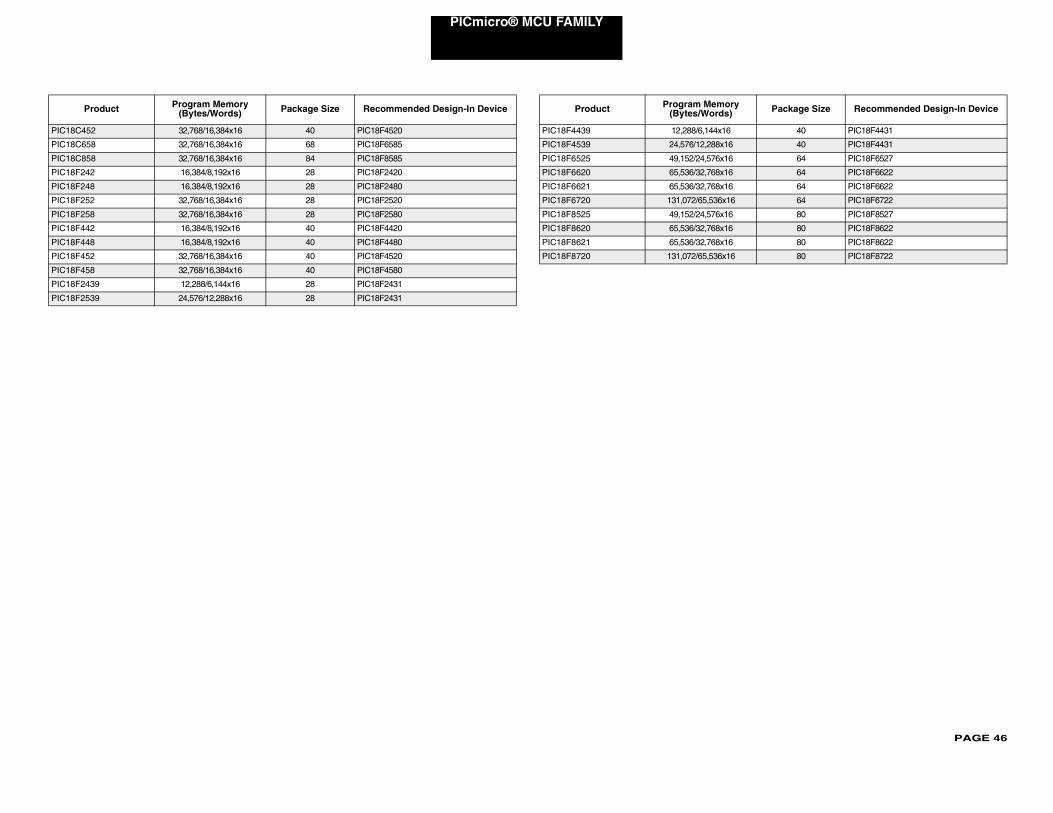
PAGE 46
PICmicro® MCU FAMILY
PIC18C4
PIC18C6
PIC18C8
PIC18F2
PIC18F2
PIC18F2
PIC18F2
PIC18F4
PIC18F4
PIC18F4
PIC18F4
PIC18F2
PIC18F2
40 PIC18F4431
40 PIC18F4431
64 PIC18F6527
64 PIC18F6622
64 PIC18F6622
6 64 PIC18F6722
80 PIC18F8527
80 PIC18F8622
80 PIC18F8622
6 80 PIC18F8722
ry Package Size Recommended Design-In Device
52 32,768/16,384x16 40 PIC18F4520
58 32,768/16,384x16 68 PIC18F6585
58 32,768/16,384x16 84 PIC18F8585
42 16,384/8,192x16 28 PIC18F2420
48 16,384/8,192x16 28 PIC18F2480
52 32,768/16,384x16 28 PIC18F2520
58 32,768/16,384x16 28 PIC18F2580
42 16,384/8,192x16 40 PIC18F4420
48 16,384/8,192x16 40 PIC18F4480
52 32,768/16,384x16 40 PIC18F4520
58 32,768/16,384x16 40 PIC18F4580
439 12,288/6,144x16 28 PIC18F2431
539 24,576/12,288x16 28 PIC18F2431
Product Program Memory (Bytes/Words) Package Size Recommended Design-In Device
PIC18F4439 12,288/6,144x16
PIC18F4539 24,576/12,288x16
PIC18F6525 49,152/24,576x16
PIC18F6620 65,536/32,768x16
PIC18F6621 65,536/32,768x16
PIC18F6720 131,072/65,536x1
PIC18F8525 49,152/24,576x16
PIC18F8620 65,536/32,768x16
PIC18F8621 65,536/32,768x16
PIC18F8720 131,072/65,536x1
Product Program Memo(Bytes/Words)
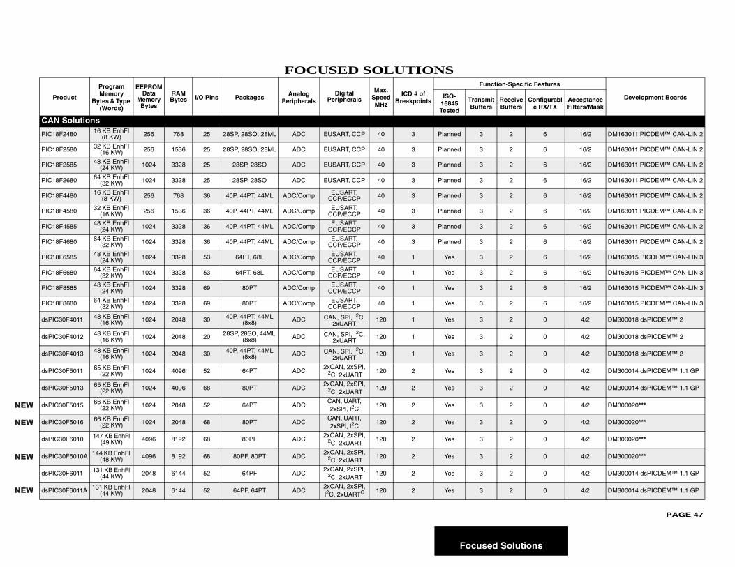
PAGE 47
tions
Pr
cific Features
Development Boardse Configurable RX/TX
Acceptance Filters/Mask
CAN
PIC18 6 16/2 DM163011 PICDEM™ CAN-LIN 2
PIC18 6 16/2 DM163011 PICDEM™ CAN-LIN 2
PIC18 6 16/2 DM163011 PICDEM™ CAN-LIN 2
PIC18 6 16/2 DM163011 PICDEM™ CAN-LIN 2
PIC18 6 16/2 DM163011 PICDEM™ CAN-LIN 2
PIC18 6 16/2 DM163011 PICDEM™ CAN-LIN 2
PIC18 6 16/2 DM163011 PICDEM™ CAN-LIN 2
PIC18 6 16/2 DM163011 PICDEM™ CAN-LIN 2
PIC18 6 16/2 DM163015 PICDEM™ CAN-LIN 3
PIC18 6 16/2 DM163015 PICDEM™ CAN-LIN 3
PIC18 6 16/2 DM163015 PICDEM™ CAN-LIN 3
PIC18 6 16/2 DM163015 PICDEM™ CAN-LIN 3
dsPIC 0 4/2 DM300018 dsPICDEM™ 2
dsPIC 0 4/2 DM300018 dsPICDEM™ 2
dsPIC 0 4/2 DM300018 dsPICDEM™ 2
dsPIC 0 4/2 DM300014 dsPICDEM™ 1.1 GP
dsPIC 0 4/2 DM300014 dsPICDEM™ 1.1 GP
dsPIC 0 4/2 DM300020***
dsPIC 0 4/2 DM300020***
dsPIC 0 4/2 DM300020***
dsPIC 0 4/2 DM300020***
dsPIC 0 4/2 DM300014 dsPICDEM™ 1.1 GP
dsPIC 0 4/2 DM300014 dsPICDEM™ 1.1 GP
NEW
NEW
NEW
NEW
Focused Solu
FOCUSED SOLUTIONS
oduct
Program Memory
Bytes & Type (Words)
EEPROM Data
Memory Bytes
RAM Bytes I/O Pins Packages Analog
PeripheralsDigital
Peripherals
Max. Speed MHz
ICD # of Breakpoints
Function-Spe
ISO-16845 Tested
Transmit Buffers
ReceivBuffers
Solutions
F2480 16 KB EnhFI (8 KW) 256 768 25 28SP, 28SO, 28ML ADC EUSART, CCP 40 3 Planned 3 2
F2580 32 KB EnhFI (16 KW) 256 1536 25 28SP, 28SO, 28ML ADC EUSART, CCP 40 3 Planned 3 2
F2585 48 KB EnhFI (24 KW) 1024 3328 25 28SP, 28SO ADC EUSART, CCP 40 3 Planned 3 2
F2680 64 KB EnhFI (32 KW) 1024 3328 25 28SP, 28SO ADC EUSART, CCP 40 3 Planned 3 2
F4480 16 KB EnhFI (8 KW) 256 768 36 40P, 44PT, 44ML ADC/Comp EUSART,
CCP/ECCP 40 3 Planned 3 2
F4580 32 KB EnhFI (16 KW) 256 1536 36 40P, 44PT, 44ML ADC/Comp EUSART,
CCP/ECCP 40 3 Planned 3 2
F4585 48 KB EnhFI (24 KW) 1024 3328 36 40P, 44PT, 44ML ADC/Comp EUSART,
CCP/ECCP 40 3 Planned 3 2
F4680 64 KB EnhFI (32 KW) 1024 3328 36 40P, 44PT, 44ML ADC/Comp EUSART,
CCP/ECCP 40 3 Planned 3 2
F6585 48 KB EnhFI (24 KW) 1024 3328 53 64PT, 68L ADC/Comp EUSART,
CCP/ECCP 40 1 Yes 3 2
F6680 64 KB EnhFI (32 KW) 1024 3328 53 64PT, 68L ADC/Comp EUSART,
CCP/ECCP 40 1 Yes 3 2
F8585 48 KB EnhFI (24 KW) 1024 3328 69 80PT ADC/Comp EUSART,
CCP/ECCP 40 1 Yes 3 2
F8680 64 KB EnhFI (32 KW) 1024 3328 69 80PT ADC/Comp EUSART,
CCP/ECCP 40 1 Yes 3 2
30F4011 48 KB EnhFl (16 KW) 1024 2048 30 40P, 44PT, 44ML
(8x8) ADC CAN, SPI, I2C, 2xUART
120 1 Yes 3 2
30F4012 48 KB EnhFl (16 KW) 1024 2048 20 28SP, 28SO, 44ML
(8x8) ADC CAN, SPI, I2C, 2xUART
120 1 Yes 3 2
30F4013 48 KB EnhFl (16 KW) 1024 2048 30 40P, 44PT, 44ML
(8x8) ADC CAN, SPI, I2C, 2xUART
120 1 Yes 3 2
30F5011 65 KB EnhFl (22 KW) 1024 4096 52 64PT ADC
2xCAN, 2xSPI, I2C, 2xUART
120 2 Yes 3 2
30F5013 65 KB EnhFl (22 KW) 1024 4096 68 80PT ADC
2xCAN, 2xSPI, I2C, 2xUART
120 2 Yes 3 2
30F5015 66 KB EnhFl (22 KW) 1024 2048 52 64PT ADC
CAN, UART, 2xSPI, I2C
120 2 Yes 3 2
30F5016 66 KB EnhFl (22 KW) 1024 2048 68 80PT ADC
CAN, UART, 2xSPI, I2C
120 2 Yes 3 2
30F6010 147 KB EnhFl (49 KW) 4096 8192 68 80PF ADC
2xCAN, 2xSPI, I2C, 2xUART
120 2 Yes 3 2
30F6010A 144 KB EnhFl (48 KW) 4096 8192 68 80PF, 80PT ADC
2xCAN, 2xSPI, I2C, 2xUART
120 2 Yes 3 2
30F6011 131 KB EnhFl (44 KW) 2048 6144 52 64PF ADC
2xCAN, 2xSPI, I2C, 2xUART
120 2 Yes 3 2
30F6011A 131 KB EnhFl (44 KW) 2048 6144 52 64PF, 64PT ADC
2xCAN, 2xSPI, I2C, 2xUARTC 120 2 Yes 3 2
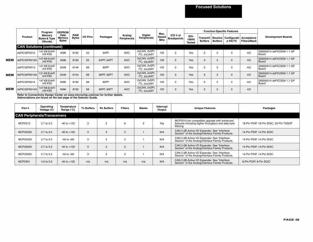
PAGE 48
Focused Solutions
CAN
dsPIC3 0 4/2 DM300014 dsPICDEM 1.1 GP Board
dsPIC3 0 4/2 DM300014 dsPICDEM 1.1 GP Board
dsPIC3 0 4/2 DM300014 dsPICDEM 1.1 GP Board
dsPIC3 0 4/2 DM300014 dsPICDEM 1.1 GP Board
dsPIC3 0 4/2 DM300014 dsPICDEM 1.1 GP Board
dsPIC3 0 4/2
Refer tAbbre
Par Packages
CAN P
MCP2enhanced d data byte 18-Pin PDIP, 18-Pin SOIC, 20-Pin TSSOP
MCP2 terface Products. 14-Pin PDIP, 14-Pin SOIC
MCP2 terface Products. 14-Pin PDIP, 14-Pin SOIC
MCP2 terface Products. 14-Pin PDIP, 14-Pin SOIC
MCP2 terface Products. 14-Pin PDIP, 14-Pin SOIC
MCP2 terface Products. 8-Pin PDIP, 8-Pin SOIC
Pro
ific Features
Development Boards Configurable RX/TX
Acceptance Filters/Mask
NEW
NEW
NEW
Solutions (continued)
0F6012 147 KB EnhFl (49 KW) 4096 8192 52 64PF ADC
2xCAN, 2xSPI, I2C, 2xUART
120 2 Yes 3 2
0F6012A 147 KB EnhFl (49 KW) 4096 8192 52 64PF, 64PT ADC
2xCAN, 2xSPI, I2C, 2xUART
120 2 Yes 3 2
0F6013 131 KB EnhFl (44 KW) 2048 6144 68 80PF ADC
2xCAN, 2xSPI, I2C, 2xUART
120 2 Yes 3 2
0F6013A 131 KB EnhFl (44 KW) 2048 6144 68 80PF, 80PT ADC
2xCAN, 2xSPI, I2C, 2xUART
120 2 Yes 3 2
0F6014 147 KB EnhFl (49 KW) 4096 8192 68 80PF ADC
2xCAN, 2xSPI, I2C, 2xUART
120 2 Yes 3 2
0F6014A 147 KB EnhFl (49 KW) 4096 8192 68 80PF, 80PT ADC
2xCAN, 2xSPI, I2C, 2xUART
120 2 Yes 3 2
o Connectivity Design Center on www.microchip.com/can for further details.viations are found on the last page of the Selector Guide.
t # Operating Voltage (V)
Temperature Range (°C) Tx Buffers Rx Buffers Filters Masks Interrupt
Output Unique Features
eripherals/Transceivers
515 2.7 to 5.5 -40 to +125 3 2 6 2 YesMCP2510 pin compatible upgrade with features including higher throughput anfiltering
5020 2.7 to 5.5 -40 to +125 3 2 2 1 N/A CAN 2.0B Active I/O Expander. See “InSection” of the Analog/Interface Family
5025 2.7 to 5.5 -40 to +85 3 2 2 1 N/A CAN 2.0B Active I/O Expander. See “InSection” of the Analog/Interface Family
5050 2.7 to 5.5 -40 to +125 3 2 2 1 N/A CAN 2.0B Active I/O Expander. See “InSection” of the Analog/Interface Family
5055 2.7 to 5.5 -40 to +85 3 2 2 1 N/A CAN 2.0B Active I/O Expander. See “InSection” of the Analog/Interface Family
551 4.5 to 5.5 -40 to +125 n/a n/a n/a n/a N/A CAN 2.0B Active I/O Expander. See “InSection” of the Analog/Interface Family
duct
Program Memory
Bytes & Type (Words)
EEPROM Data
Memory Bytes
RAM Bytes I/O Pins Packages Analog
PeripheralsDigital
Peripherals
Max. Speed MHz
ICD # of Breakpoints
Function-Spec
ISO-16845 Tested
Transmit Buffers
ReceiveBuffers
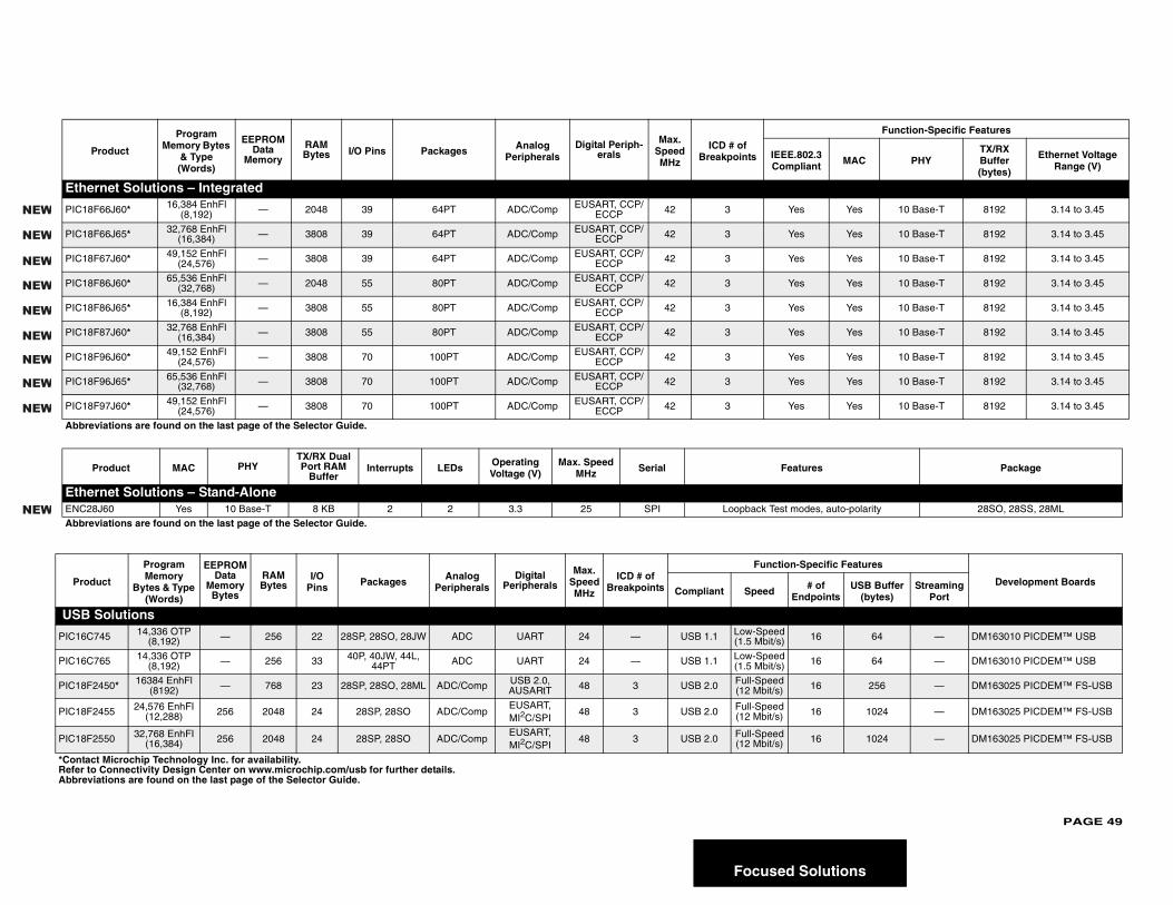
PAGE 49
lutions
P
Function-Specific Features
.3 t MAC PHY
TX/RX Buffer (bytes)
Ethernet Voltage Range (V)
Ethe
PIC18 Yes 10 Base-T 8192 3.14 to 3.45
PIC18 Yes 10 Base-T 8192 3.14 to 3.45
PIC18 Yes 10 Base-T 8192 3.14 to 3.45
PIC18 Yes 10 Base-T 8192 3.14 to 3.45
PIC18 Yes 10 Base-T 8192 3.14 to 3.45
PIC18 Yes 10 Base-T 8192 3.14 to 3.45
PIC18 Yes 10 Base-T 8192 3.14 to 3.45
PIC18 Yes 10 Base-T 8192 3.14 to 3.45
PIC18 Yes 10 Base-T 8192 3.14 to 3.45
Abbre
P s Package
EtheENC28 s, auto-polarity 28SO, 28SS, 28ML
Abbre
Prod
cific Features
Development Boardsof oints
USB Buffer (bytes)
Streaming Port
USB
PIC16C 6 64 — DM163010 PICDEM™ USB
PIC16C 6 64 — DM163010 PICDEM™ USB
PIC18F2 6 256 — DM163025 PICDEM™ FS-USB
PIC18F2 6 1024 — DM163025 PICDEM™ FS-USB
PIC18F2 6 1024 — DM163025 PICDEM™ FS-USB
*ContacRefer toAbbrevi
NEW
NEW
NEW
NEW
NEW
NEW
NEW
NEW
NEW
NEW
Focused So
roduct
Program Memory Bytes
& Type (Words)
EEPROM Data
Memory
RAM Bytes I/O Pins Packages Analog
PeripheralsDigital Periph-
erals
Max. Speed MHz
ICD # of Breakpoints IEEE.802
Complian
rnet Solutions – Integrated
F66J60* 16,384 EnhFl (8,192) — 2048 39 64PT ADC/Comp EUSART, CCP/
ECCP 42 3 Yes
F66J65* 32,768 EnhFl (16,384) — 3808 39 64PT ADC/Comp EUSART, CCP/
ECCP 42 3 Yes
F67J60* 49,152 EnhFl (24,576) — 3808 39 64PT ADC/Comp EUSART, CCP/
ECCP 42 3 Yes
F86J60* 65,536 EnhFl (32,768) — 2048 55 80PT ADC/Comp EUSART, CCP/
ECCP 42 3 Yes
F86J65* 16,384 EnhFl (8,192) — 3808 55 80PT ADC/Comp EUSART, CCP/
ECCP 42 3 Yes
F87J60* 32,768 EnhFl (16,384) — 3808 55 80PT ADC/Comp EUSART, CCP/
ECCP 42 3 Yes
F96J60* 49,152 EnhFl (24,576) — 3808 70 100PT ADC/Comp EUSART, CCP/
ECCP 42 3 Yes
F96J65* 65,536 EnhFl (32,768) — 3808 70 100PT ADC/Comp EUSART, CCP/
ECCP 42 3 Yes
F97J60* 49,152 EnhFl (24,576) — 3808 70 100PT ADC/Comp EUSART, CCP/
ECCP 42 3 Yes
viations are found on the last page of the Selector Guide.
roduct MAC PHYTX/RX Dual Port RAM
BufferInterrupts LEDs Operating
Voltage (V)Max. Speed
MHz Serial Feature
rnet Solutions – Stand-AloneJ60 Yes 10 Base-T 8 KB 2 2 3.3 25 SPI Loopback Test mode
viations are found on the last page of the Selector Guide.
uct
Program Memory
Bytes & Type (Words)
EEPROM Data
Memory Bytes
RAM Bytes
I/O Pins Packages Analog
PeripheralsDigital
Peripherals
Max. Speed MHz
ICD # of Breakpoints
Function-Spe
Compliant Speed # Endp
Solutions
745 14,336 OTP (8,192) — 256 22 28SP, 28SO, 28JW ADC UART 24 — USB 1.1 Low-Speed
(1.5 Mbit/s) 1
765 14,336 OTP (8,192) — 256 33 40P, 40JW, 44L,
44PT ADC UART 24 — USB 1.1 Low-Speed (1.5 Mbit/s) 1
450* 16384 EnhFl (8192) — 768 23 28SP, 28SO, 28ML ADC/Comp USB 2.0,
AUSARtT 48 3 USB 2.0 Full-Speed (12 Mbit/s) 1
455 24,576 EnhFI (12,288) 256 2048 24 28SP, 28SO ADC/Comp
EUSART, MI2C/SPI
48 3 USB 2.0 Full-Speed (12 Mbit/s) 1
550 32,768 EnhFI (16,384) 256 2048 24 28SP, 28SO ADC/Comp
EUSART, MI2C/SPI
48 3 USB 2.0 Full-Speed (12 Mbit/s) 1
t Microchip Technology Inc. for availability. Connectivity Design Center on www.microchip.com/usb for further details.ations are found on the last page of the Selector Guide.
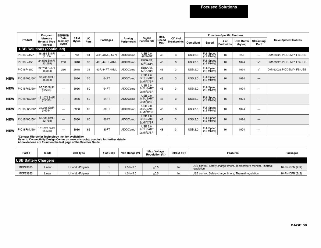
PAGE 50
Focused Solutions
USB
PIC18 16 256 — DM163025 PICDEM™ FS-USB
PIC18 16 1024 ✓ DM163025 PICDEM™ FS-USB
PIC18 16 1024 ✓ DM163025 PICDEM™ FS-USB
PIC18 16 1024 —
PIC18 16 1024 —
PIC18 16 1024 —
PIC18 16 1024 —
PIC18 16 1024 —
PIC18 16 1024 —
Pa Features Packages
USB B
MCP7 ge timers, Temperature monitor, Thermal 16-Pin QFN (4x4)
MCP7 ge timers, Thermal regulation 10-Pin DFN (3x3)
Pro
pecific Features
Development Boards# of points
USB Buffer (bytes)
Streaming Port
*ContaRefer Abbre
NEW
NEW
NEW
NEW
NEW
NEW
Solutions (continued)
F4450* 16,384 EnhFl (8183) — 768 34 40P, 44ML, 44PT ADC/Comp USB 2.0,
AUSART 48 3 USB 2.0 Full-Speed (12 Mbit/s)
F4455 24,576 EnhFI (12,288) 256 2048 36 40P, 44PT, 44ML ADC/Comp
EUSART, MI2C/SPI
48 3 USB 2.0 Full-Speed (12 Mbit/s)
F4550 32,768 EnhFI (16,384) 256 2048 36 40P, 44PT, 44ML ADC/Comp
EUSART, MI2C/SPI
48 3 USB 2.0 Full-Speed (12 Mbit/s)
F65J50* 32,768 StdFl (16,384) 3936 50 64PT ADC/Comp
USB 2.0, 2xEUSART,2xMI2C/SPI
48 3 USB 2.0 Full-Speed (12 Mbit/s)
F66J50* 65,536 StdFl (32768) — 3936 50 64PT ADC/Comp
USB 2.0, 2xEUSART, 2xMI2C/SPI
48 3 USB 2.0 Full-Speed (12 Mbit/s)
F67J50* 131,072 StdFl (65536) — 3936 50 64PT ADC/Comp
USB 2.0, 2xEUSART, 2xMI2C/SPI
48 3 USB 2.0 Full-Speed (12 Mbit/s)
F85J50* 32,768 StdFl (16384) — 3936 66 80PT ADC/Comp
USB 2.0, 2xEUSART, 2xMI2C/SPI
48 3 USB 2.0 Full-Speed (12 Mbit/s)
F86J50* 65,536 StdFl (32,768) — 3936 66 80PT ADC/Comp
USB 2.0, 2xEUSART,2xMI2C/SPI
48 3 USB 2.0 Full-Speed (12 Mbit/s)
F87J50* 131,072 StdFl (65,536) — 3936 66 80PT ADC/Comp
USB 2.0, 2xEUSART,2xMI2C/SPI
48 3 USB 2.0 Full-Speed (12 Mbit/s)
rt # Mode Cell Type # of Cells VCC Range (V) Max. Voltage Regulation (%) Int/Ext FET
attery Chargers
3853 Linear Li-Ion/Li-Polymer 1 4.5 to 5.5 +0.5 Int USB control, Safety charregulation
3855 Linear Li-Ion/Li-Polymer 1 4.5 to 5.5 +0.5 Int USB control, Safety char
duct
Program Memory
Bytes & Type (Words)
EEPROM Data
Memory Bytes
RAM Bytes
I/O Pins Packages Analog
PeripheralsDigital
Peripherals
Max. Speed MHz
ICD # of Breakpoints
Function-S
Compliant Speed End
ct Microchip Technology Inc. for availability.to Connectivity Design Center on www.microchip.com/usb for further details.viations are found on the last page of the Selector Guide.
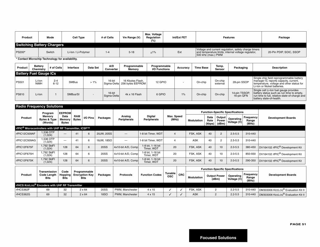
PAGE 51
tions
Pro atures Package
Switch
PS200*lation, safety charge timers
nternal voltage regulator, 20-Pin PDIP, SOIC, SSOP
* Contac
Produc Packaging Description
Batter
PS501 28-pin SSOP
Single chip field reprogrammable battery manager IC reports capacity, current, temperature, voltage and other status for Li-Ion or Nickel batteries.
PS810 14-pin TSSOP, 16-pin QFN
Single cell Li-Ion fuel gauge provides battery status such as run time to empty, run time to full, relative state-of-charge and battery state-of-health.
Radio
Pro
pecifications
Development Boards Operating Voltage (V)
Frequency Range (MHz)
rfPIC® M
rfPIC12C 2.5-5.5 310-440
rfPIC12C 2.5-5.5 310-440
rfPIC12F 2.0-5.5 380-450 DV164102 rfPIC® Development Kit
rfPIC12F 2.0-5.5 850-930 DV164102 rfPIC® Development Kit
rfPIC12F 2.0-5.5 290-350 DV164102 rfPIC® Development Kit
Pro
pecifications
Development BoardsOperating Voltage (V)
Frequency Range (MHz)
rfHCS K
rfHCS36 2.2-5.5 310-440 DM303006 KEELOQ® Evaluation Kit II
rfHCS36 2.2-5.5 310-440 DM303006 KEELOQ® Evaluation Kit II
Focused Solu
duct Mode Cell Type # of Cells VIN Range (V)Max. Voltage Regulation
(%)Int/Ext FET Fe
ing Battery Chargers
Switch Li-Ion / Li-Polymer 1-4 5-18 +1% ExtVoltage and current reguand temperature limits, i500 kHz (max.) PWM
t Microchip Technology for availability.
t Battery Chemistry # of Cells Interface Data Set A/D
ConverterProgrammable
MemoryProgrammable I/O Functions Accuracy Time Base Temp.
Sensor
y Fuel Gauge ICs
Li-IonNiMH
2-46-12 SMBus > 1% 16-bit
Sigma-Delta16 Kbytes Flash,
256 bytes EEPROM 12 GPIO - On-chip On-chip external
Li-Ion 1 SMBus/SI - 16-bit Sigma-Delta 4k x 16 Flash 6 GPIO 1% On-chip On-chip
Frequency Solutions
duct
Program Memory
Bytes & Type (Words)
EEPROM Data
Memory Bytes
RAM Bytes I/O Pins Packages Analog
PeripheralsDigital
PeripheralsMax. Speed
(MHz)
Function-Specific S
ModulationData Rate
(kbps)
OutputPower (dBm)
icrocontrollers with UHF RF Transmitter, ICSP™
509AF 1,536 OTP (1,024) — 41 6 20JW, 20SS — 1-8 bit Timer, WDT 4 FSK, ASK 40 2
509AG 1,536 OTP (1,024) — 41 6 18JW, 18SO — 1-8 bit Timer, WDT 4 ASK 40 2
675F 1,792 StdFI (1,024) 128 64 6 20SS 4x10-bit A/D, Comp 1-8 bit, 1-16 bit
Timer, WDT 20 FSK, ASK 40 10
675H 1,792 StdFI (1,024) 128 64 6 20SS 4x10-bit A/D, Comp 1-8 bit, 1-16 bit
Timer, WDT 20 FSK, ASK 40 10
675K 1,792 StdFI (1,024) 128 64 6 20SS 4x10-bit A/D, Comp 1-8 bit, 1-16 bit
Timer, WDT 20 FSK, ASK 40 10
ductTransmission Code Length
Bits
Code Hopping
Bits
Programmable Encryption Key
BitsPackages Protocols Function Codes Tunable
OSC CRC
Function-Specific S
Modulation Output Power (dBm)
EELOQ® Encoders with UHF RF Transmitter
2F 69 32 2 x 64 20SS PWM, Manchester 4 x 15 ✓ ✓ FSK, ASK 2
2G 69 32 2 x 64 18SO PWM, Manchester 4 x 15 ✓ ✓ ASK 2
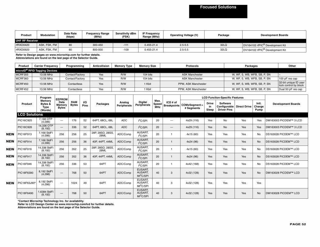
PAGE 52
Focused Solutions
Pro kage Development Boards
UHF RF
rfRXD04 2LQ DV164102 rfPIC® Development Kit
rfRXD09 2LQ DV164102 rfPIC® Development Kit
Refer toAbbrevi
Produ Packages Other
microIDMCRF35 W, WF, S, WB, WFB, SB, P, SN –
MCRF36 W, WF, S, WB, WFB, SB, P, SN 100 pF res cap
MCRF45 W, WF, S, WB, WFB, SB, P, SN 32-bit unique ID user lock control by block
MCRF45 W, WF, S, WB, WFB, SB, P, SN Dual 50 pF res cap
Pro
pecific Features
Development Boardsftware figurable ver Pins
Direct DriveIntl.
Charge Pump
LCD
PIC16C No Yes Yes DM163003 PICDEM™ 3 LCD
PIC16C No Yes Yes DM163003 PICDEM™ 3 LCD
PIC16 Yes Yes No DS163028 PICDEM™ LCD
PIC16 Yes Yes No DS163028 PICDEM™ LCD
PIC16 Yes Yes No DS163028 PICDEM™ LCD
PIC16 Yes Yes No DS163028 PICDEM™ LCD
PIC16 Yes Yes No DS163028 PICDEM™ LCD
PIC18 Yes Yes No DM163028 PICDEM™ LCD
PIC18 Yes Yes Yes
PIC18 Yes Yes No DM163028 PICDEM™ LCD
*ContaRefer Abbre
NEW
NEW
NEW
NEW
NEW
NEW
duct Modulation Data Rate (kbps)
Frequency Range (MHz)
Sensitivity dBm (FSK)
IF Frequency Range (MHz) Operating Voltage (V) Pac
Receiver
20 ASK, FSK, FM 80 300-450 -111 0.455-21.4 2.5-5.5 3
20 ASK, FSK, FM 80 800-930 -109 0.455-21.4 2.5-5.5 3
Design pages on www.microchip.com for further details.ations are found on the last page of the Selector Guide.
ct Carrier Frequency Programming Anticollision Memory Type Memory Size Protocols® RFID Tagging Devices5 13.56 MHz Contact/Factory Yes R/W 154 bits ASK Manchester
0 13.56 MHz Contact/Factory Yes R/W 154 bits ASK Manchester
0 13.56 MHz Contactless Yes R/W 1 Kbit PPM, ASK Manchester
2 13.56 MHz Contactless Yes R/W 1 Kbit PPM, ASK Manchester
duct
Program Memory Bytes &
Type (Words)
EEPROMData
Memory Bytes
RAM Bytes
I/O Pins Packages Analog
PeripheralsDigital
Peripherals
Max. Speed MHz
ICD # of Breakpoints
LCD Function-S
COMxSegment = # Segments
Drive in
Sleep
SoConDri
Solutions
925 7,168 OTP (4,096) — 176 52 64PT, 68CL, 68L ADC I2C/SPI 20 — 4x29 (116) Yes
926 14,336 OTP (8,192) — 336 52 64PT, 68CL, 68L ADC I2C/SPI 20 — 4x29 (116) Yes
F913 7,168 StdFI (4,096) 256 256 25 28P, 28SO, 28SS,
28ML ADC/CompAUSART, I2C/SPI
20 1 4x15 (60) Yes
F914 7,168 StdFI (4,096) 256 256 36 40P, 44PT, 44ML ADC/Comp
AUSART, I2C/SPI
20 1 4x24 (96) Yes
F916 14,336 StdFI (8,192) 256 352 25 28P, 28SO, 28SS,
28ML ADC/CompAUSART, I2C/SPI
20 1 4x15 (60) Yes
F917 14,336 StdFI (8,192) 256 352 36 40P, 44PT, 44ML ADC/Comp
AUSART, I2C/SPI
20 1 4x24 (96) Yes
F946 14,336 StdFI (8,192) 256 336 53 64PT ADC/Comp
AUSART, I2C/SPI
20 1 4x42 (168) Yes
F6390 8,192 StdFI (4,096) — 768 50 64PT ADC/Comp
EUSART, AUSART, MI2C/SPI
40 3 4x32 (128) Yes
F63J90* 8,192 StdFl (4,096) — 1024 49 64PT ADC/Comp
EUSART, AUSART, MI2C/SPI
40 3 4x32 (128) Yes
F6490 1,6384 StdFI (8,192) — 768 50 64PT ADC/Comp
EUSART, AUSART, MI2C/SPI
40 3 4x32 (128) Yes
ct Microchip Technology Inc. for availability.to LCD Design Center on www.microchip.com/lcd for further details.viations are found on the last page of the Selector Guide.
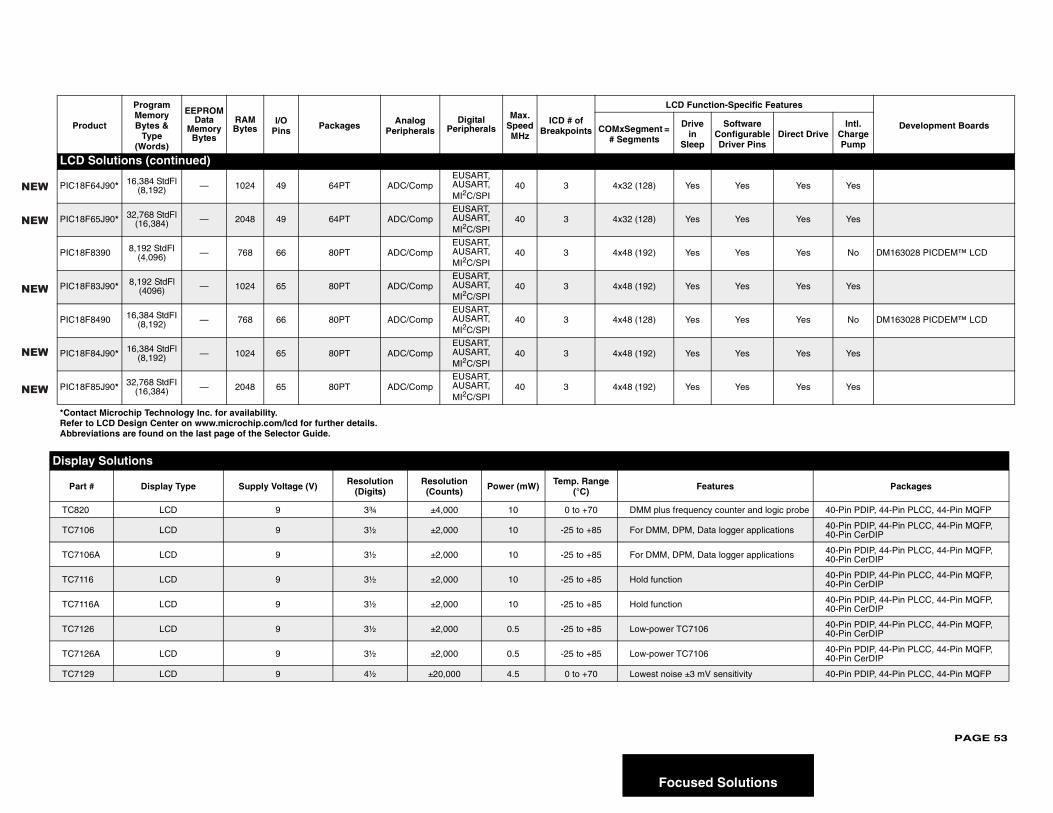
PAGE 53
lutions
LCD
PIC18 Yes Yes Yes
PIC18 Yes Yes Yes
PIC18 Yes Yes No DM163028 PICDEM™ LCD
PIC18 Yes Yes Yes
PIC18 Yes Yes No DM163028 PICDEM™ LCD
PIC18 Yes Yes Yes
PIC18 Yes Yes Yes
Displa
Part Packages
TC82 ter and logic probe 40-Pin PDIP, 44-Pin PLCC, 44-Pin MQFP
TC71 ger applications 40-Pin PDIP, 44-Pin PLCC, 44-Pin MQFP, 40-Pin CerDIP
TC71 ger applications 40-Pin PDIP, 44-Pin PLCC, 44-Pin MQFP, 40-Pin CerDIP
TC711 40-Pin PDIP, 44-Pin PLCC, 44-Pin MQFP, 40-Pin CerDIP
TC711 40-Pin PDIP, 44-Pin PLCC, 44-Pin MQFP, 40-Pin CerDIP
TC71 40-Pin PDIP, 44-Pin PLCC, 44-Pin MQFP, 40-Pin CerDIP
TC71 40-Pin PDIP, 44-Pin PLCC, 44-Pin MQFP, 40-Pin CerDIP
TC71 itivity 40-Pin PDIP, 44-Pin PLCC, 44-Pin MQFP
Pro
pecific Features
Development Boardsftware figurable ver Pins
Direct DriveIntl.
Charge Pump
*ContaRefer Abbre
NEW
NEW
NEW
NEW
NEW
Focused So
Solutions (continued)
F64J90* 16,384 StdFl (8,192) — 1024 49 64PT ADC/Comp
EUSART, AUSART, MI2C/SPI
40 3 4x32 (128) Yes
F65J90* 32,768 StdFl (16,384) — 2048 49 64PT ADC/Comp
EUSART, AUSART, MI2C/SPI
40 3 4x32 (128) Yes
F8390 8,192 StdFI (4,096) — 768 66 80PT ADC/Comp
EUSART, AUSART, MI2C/SPI
40 3 4x48 (192) Yes
F83J90* 8,192 StdFl (4096) — 1024 65 80PT ADC/Comp
EUSART, AUSART, MI2C/SPI
40 3 4x48 (192) Yes
F8490 16,384 StdFI (8,192) — 768 66 80PT ADC/Comp
EUSART, AUSART,MI2C/SPI
40 3 4x48 (128) Yes
F84J90* 16,384 StdFl (8,192) — 1024 65 80PT ADC/Comp
EUSART, AUSART,MI2C/SPI
40 3 4x48 (192) Yes
F85J90* 32,768 StdFI (16,384) — 2048 65 80PT ADC/Comp
EUSART, AUSART,MI2C/SPI
40 3 4x48 (192) Yes
y Solutions
# Display Type Supply Voltage (V) Resolution (Digits)
Resolution (Counts) Power (mW) Temp. Range
(°C) Features
0 LCD 9 3¾ ±4,000 10 0 to +70 DMM plus frequency coun
06 LCD 9 3½ ±2,000 10 -25 to +85 For DMM, DPM, Data log
06A LCD 9 3½ ±2,000 10 -25 to +85 For DMM, DPM, Data log
6 LCD 9 3½ ±2,000 10 -25 to +85 Hold function
6A LCD 9 3½ ±2,000 10 -25 to +85 Hold function
26 LCD 9 3½ ±2,000 0.5 -25 to +85 Low-power TC7106
26A LCD 9 3½ ±2,000 0.5 -25 to +85 Low-power TC7106
29 LCD 9 4½ ±20,000 4.5 0 to +70 Lowest noise ±3 mV sens
duct
Program Memory Bytes &
Type (Words)
EEPROMData
Memory Bytes
RAM Bytes
I/O Pins Packages Analog
PeripheralsDigital
Peripherals
Max. Speed MHz
ICD # of Breakpoints
LCD Function-S
COMxSegment = # Segments
Drive in
Sleep
SoConDri
ct Microchip Technology Inc. for availability.to LCD Design Center on www.microchip.com/lcd for further details.viations are found on the last page of the Selector Guide.
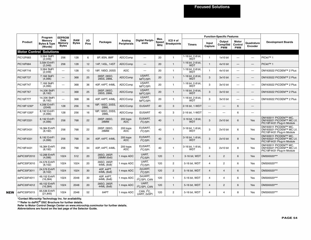
PAGE 54
Focused Solutions
Pr
-Specific Features
Development BoardsOutput Comp/Std
PWM
Motor Control
PWM
Quadrature Encoder
Moto
PIC12 1x10 bit — — PICkit™ 1
PIC16 4x10 bit — — PICkit™ 1
PIC16 4x10 bit — — DM163022 PICDEM™ 2 Plus
PIC16 3x10 bit — — DM163022 PICDEM™ 2 Plus
PIC16 3x10 bit — — DM163022 PICDEM™ 2 Plus
PIC16 3x10 bit — — DM163022 PICDEM™ 2 Plus
PIC16 3x10 bit — — DM163022 PICDEM™ 2 Plus
PIC18 — 6 —
PIC18 — 6 —
PIC18 2x10 bit 6 YesDM183011 PICDEM™ MC, DM183021 PICDEM™ MC LV, PIC18F4431 Plug-in Module
PIC18 2x10 bit 6 YesDM183011 PICDEM™ MC, DM183021 PICDEM™ MC LV, PIC18F4431 Plug-in Module
PIC18 2x10 bit 8 YesDM183011 PICDEM™ MC, DM183021 PICDEM™ MC LV, PIC18F4431 Plug-in Module
PIC18 2x10 bit 8 YesDM183011 PICDEM™ MC, DM183021 PICDEM™ MC LV, PIC18F4431 Plug-in Module
dsPIC3 2 6 Yes DM300020***
dsPIC3 2 6 Yes DM300020***
dsPIC3 4 6 Yes DM300020***
dsPIC3 4 6 Yes DM300020***
dsPIC3 2 6 Yes DM300020***
dsPIC3 4 8 Yes DM300020***
*Conta***RefRefer Abbre
NEW
oduct
Program Memory
Bytes & Type (Words)
EEPROM Data
Memory Bytes
RAM Bytes
I/O Pins Packages Analog
PeripheralsDigital Periph-
erals
Max. Speed MHz
ICD # of Breakpoints
Function
Timers Input Capture
r Control Solutions
F683 3,584 StdFI (2,048) 256 128 6 8P, 8SN, 8MF ADC/Comp — 20 1 1-16 bit, 2-8 bit,
WDT 1
F684 3,584 EnhFI (2,048) 256 128 12 14P, 14SL, 14ST ADC/Comp — 20 1 1-16 bit, 2-8 bit,
WDT 1
F716 3,584 StdFI (2,048) — 128 13 18P, 18SO, 20SS ADC — 20 1 1-16 bit, 2-8 bit,
WDT 1
F737 7,168 StdFI (4,096) — 368 25 28SP, 28SO,
28SS, 28ML ADC/CompUSART,
MI2C/SPI20 1 1-16 bit, 2-8 bit,
WDT 3
F747 7,168 StdFI (4,096) — 368 36 40P, 44PT, 44ML ADC/Comp
USART, MI2C/SPI
20 1 1-16 bit, 2-8 bit, WDT 3
F767 14,336 StdFl (8,192) — 368 25 28SP, 28SO,
28SS, 28ML ADC/CompUSART,
MI2C/SPI20 1 1-16 bit, 2-8 bit,
WDT 3
F777 14,336 StdFI (8,192) — 368 36 40P, 44PT, 44ML ADC/Comp
USART, MI2C/SPI
20 1 1-16 bit, 2-8 bit, WDT 3
F1230* 4,096 EnhFI (2048) 128 256 16 18P, 18SO, 20SS,
28ML ADC/Comp EUSART 40 3 2-16 bit, 1-WDT —
F1330* 8,192 EnhFI (4,096) 128 256 16 18P, 18SO, 20SS,
28ML ADC/Comp EUSART 40 3 2-16 bit, 1-WDT —
F2331 8,192 EnhFI (4,096) 256 768 22 28SP, 28SO,
28MM200 ksps
ADCEUSART, I2C/SPI
40 1 3-16 bit, 1-8 bit, WDT 3
F2431 16,384 EnhFI (8,192) 256 768 22 28SP, 28SO,
28MM200 ksps
ADCEUSART, I2C/SPI
40 1 3-16 bit, 1-8 bit, WDT 3
F4331 8,192 EnhFI (4,096) 256 768 34 40P, 44PT, 44ML 200 ksps
ADCEUSART, I2C/SPI
40 1 3-16 bit, 1-8 bit, WDT 3
F4431 16,384 EnhFI (8,192) 256 768 34 40P, 44PT, 44ML 200 ksps
ADCEUSART, I2C/SPI
40 1 3-16 bit, 1-8 bit, WDT 3
0F2010 12,288 EnhFl (4,096) 1024 512 20 28SO, 28SP,
28MM (6x6) 1 msps ADCUART,I2C/SPI
120 1 3-16 bit, WDT 4
0F3010 24,576 EnhFl (8,102) 1024 1024 20 28SO, 28SP,
44ML (8x8) 1 msps ADCUART,I2C/SPI
120 2 5-16 bit, WDT 4
0F3011 24,576 EnhFl (8,102) 1024 1024 30 40P, 44PT,
44ML (8x8) 1 msps ADC2xUART,I2C/SPI
120 2 5-16 bit, WDT 4
0F4011 49,152 EnhFl (16,384) 1024 2048 30 40P, 44PT,
44ML (8x8) 1 msps ADC2xUART,
I2C/SPI, CAN120 1 5-16 bit, WDT 4
0F4012 49,152 EnhFl (16,384) 1024 2048 20 28SO, 28SP,
44ML (8x8) 1 msps ADCUART,
I2C/SPI, CAN120 1 5-16 bit, WDT 4
0F5015 65,536 EnhFl (21,845) 1024 2048 52 64PT 1 msps ADC CAN, I2C,
UART, 2xSPI120 2 5-16 bit, WDT 4
ct Microchip Technology Inc. for availability.er to dsPIC® DSC Brochure for further details.to Motor Control Design Center on www.microchip.com/motor for further details.viations are found on the last page of the Selector Guide.
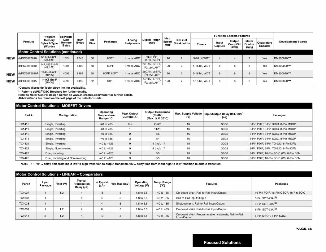
PAGE 55
lutions
Moto
dsPIC3 4 8 Yes DM300020***
dsPIC3 8 8 Yes DM300020***
dsPIC3 8 8 Yes DM300020***
dsPIC3 8 8 Yes DM300020***
Motor
P ay (td1, td2)(1) )
Packages
TC14 0 8-Pin PDIP, 8-Pin SOIC, 8-Pin MSOP
TC14 0 8-Pin PDIP, 8-Pin SOIC, 8-Pin MSOP
TC14 5 8-Pin PDIP, 8-Pin SOIC, 8-Pin MSOP
TC14 5 8-Pin PDIP, 8-Pin SOIC, 8-Pin MSOP
TC44 3 8-Pin PDIP, 5-Pin TO-220, 8-Pin DFN
TC44 3 8-Pin PDIP, 5-Pin TO-220, 8-Pin DFN
TC44 8 8-Pin PDIP, 16-Pin SOIC (W), 8-Pin DFN
TC44 8 8-Pin PDIP, 16-Pin SOIC (W), 8-Pin DFN
NOT
Motor
Par Packages
TC10 16-Pin PDIP, 16-Pin QSOP, 16-Pin SOIC
TC10 5-Pin SOT-23A(S)
TC10 6-Pin SOT-23A(S)
TC10 6-Pin SOT-23A(S)
TC10 is, Rail-to-Rail 8-Pin MSOP, 8-Pin SOIC
Pr
Specific Features
Development BoardsOutput Comp/Std
PWM
Motor Control
PWM
Quadrature Encoder
*Conta***RefRefer Abbre
NEW
NEW
NEW
Focused So
r Control Solutions (continued)
0F5016 65,536 EnhFl (21,845) 1024 2048 68 80PT 1 msps ADC CAN, I2C,
UART, 2xSPI120 2 5-16 bit WDT 4
0F6010 147,456 EnhFl (49,152) 4096 8192 68 80PF 1 msps ADC
2xCAN, 2xSPI, I2C, 2xUART
120 2 5-16 bit, WDT 8
0F6010A 144KB EnhFl (48KW) 4096 8192 68 80PF, 80PT 1 msps ADC
2xCAN, 2xSPI, I2C, 2xUART
120 2 5-16 bit, WDT 8
0F6015 144KB EnhFl (48KW) 4096 8192 52 64PT 1 msps ADC
2xCAN, 2xSPI, I2C, 2xUART
120 2 5 16-bit, WDT 8
Control Solutions - MOSFET Drivers
art # ConfigurationOperating
Temperature Range (°C)
Peak Output Current (A)
Output Resistance (RH/RL)
(Max. Ω @ 25°C)
Max. Supply Voltage (V)
Input/Output Del(ns
10 Single, Inverting -40 to +85 0.5 22/22 16 30/3
11 Single, Inverting -40 to +85 1 11/11 16 30/3
12 Single, Inverting -40 to +85 2 6/6 16 35/3
13 Single, Inverting -40 to +85 3 4/4 16 35/3
21 Single, Inverting -40 to +125 9 1.4 (typ)/1.7 18 30/3
22 Single, Non-inverting -40 to +125 9 1.4 (typ)/1.7 18 30/3
23 Dual, Inverting -40 to +125 3 5/5 18 33/3
25 Dual, Inverting and Non-inverting -40 to +125 3 5/5 18 33/3
E 1: *tD1 = delay time from input low-to-high transition to output transition. tD2 = delay time from input high-to-low transition to output transition.
Control Solutions - LINEAR – Comparators
t # # per Package VREF (V)
TypicalPropagation Delay (μs)
IQ Typical (μA) VOS Max (mV) Operating
Voltage (V)Temp. Range
(°C) Features
27 4 1.2 4 18 5 1.8 to 5.5 -40 to +85 On-board VREF, Rail-to-Rail Input/Output
37 1 — 4 4 5 1.8 to 5.5 -40 to +85 Rail-to-Rail Input/Output
38 1 — 4 4 5 1.8 to 5.5 -40 to +85 Shutdown pin, Rail-to-Rail Input/Output
39 1 1.2 4 6 5 1.8 to 5.5 -40 to +85 On-board VREF, Rail-to-Rail Input/Output
41 2 1.2 4 10 5 1.8 to 5.5 -40 to +85 On-board VREF, Programmable hysteresInput/Output
oduct
Program Memory
Bytes & Type (Words)
EEPROM Data
Memory Bytes
RAM Bytes
I/O Pins Packages Analog
PeripheralsDigital Periph-
erals
Max. Speed MHz
ICD # of Breakpoints
Function-
Timers Input Capture
ct Microchip Technology Inc. for availability.er to dsPIC® DSC Brochure for further details.to Motor Control Design Center on www.microchip.com/motor for further details.viations are found on the last page of the Selector Guide.
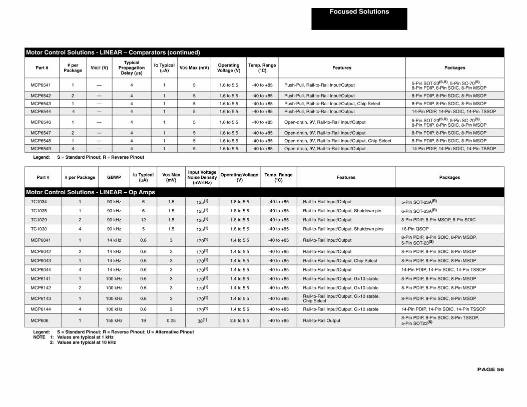
PAGE 56
Focused Solutions
MCP6 5-Pin SOT-23(S,R), 5-Pin SC-70(S), 8-Pin PDIP, 8-Pin SOIC, 8-Pin MSOP
MCP6 8-Pin PDIP, 8-Pin SOIC, 8-Pin MSOP
MCP6 Select 8-Pin PDIP, 8-Pin SOIC, 8-Pin MSOP
MCP6 14-Pin PDIP, 14-Pin SOIC, 14-Pin TSSOP
MCP6 5-Pin SOT-23(S,R), 5-Pin SC-70(S), 8-Pin PDIP, 8-Pin SOIC, 8-Pin MSOP
MCP6 8-Pin PDIP, 8-Pin SOIC, 8-Pin MSOP
MCP6 , Chip Select 8-Pin PDIP, 8-Pin SOIC, 8-Pin MSOP
MCP6 14-Pin PDIP, 14-Pin SOIC, 14-Pin TSSOP
Lege
Pa Packages
Motor
TC103 5-Pin SOT-23A(R)
TC103 own pin 6-Pin SOT-23A(R)
TC102 8-Pin PDIP, 8-Pin MSOP, 8-Pin SOIC
TC103 own pins 16-Pin QSOP
MCP68-Pin PDIP, 8-Pin SOIC, 8-Pin MSOP, 5-Pin SOT-23(S)
MCP6 8-Pin PDIP, 8-Pin SOIC, 8-Pin MSOP
MCP6 elect 8-Pin PDIP, 8-Pin SOIC, 8-Pin MSOP
MCP6 14-Pin PDIP, 14-Pin SOIC, 14-Pin TSSOP
MCP6 stable 8-Pin PDIP, 8-Pin SOIC, 8-Pin MSOP
MCP6 stable 8-Pin PDIP, 8-Pin SOIC, 8-Pin MSOP
MCP6 stable, 8-Pin PDIP, 8-Pin SOIC, 8-Pin MSOP
MCP6 stable 14-Pin PDIP, 14-Pin SOIC, 14-Pin TSSOP
MCP68-Pin PDIP, 8-Pin SOIC, 8-Pin TSSOP, 5-Pin SOT23(S)
LegeNOT
Motor
Par Packages
541 1 — 4 1 5 1.6 to 5.5 -40 to +85 Push-Pull, Rail-to-Rail Input/Output
542 2 — 4 1 5 1.6 to 5.5 -40 to +85 Push-Pull, Rail-to-Rail Input/Output
543 1 — 4 1 5 1.6 to 5.5 -40 to +85 Push-Pull, Rail-to-Rail Input/Output, Chip
544 4 — 4 1 5 1.6 to 5.5 -40 to +85 Push-Pull, Rail-to-Rail Input/Output
546 1 — 4 1 5 1.6 to 5.5 -40 to +85 Open-drain, 9V, Rail-to-Rail Input/Output
547 2 — 4 1 5 1.6 to 5.5 -40 to +85 Open-drain, 9V, Rail-to-Rail Input/Output
548 1 — 4 1 5 1.6 to 5.5 -40 to +85 Open-drain, 9V, Rail-to-Rail Input/Output
549 4 — 4 1 5 1.6 to 5.5 -40 to +85 Open-drain, 9V, Rail-to-Rail Input/Output
nd: S = Standard Pinout; R = Reverse Pinout
rt # # per Package GBWP IQ Typical (μA)
VOS Max (mV)
Input Voltage Noise Density
(nV/rtHz)
Operating Voltage (V)
Temp. Range (°C) Features
Control Solutions - LINEAR – Op Amps
4 1 90 kHz 6 1.5 125(1) 1.8 to 5.5 -40 to +85 Rail-to-Rail Input/Output
5 1 90 kHz 6 1.5 125(1) 1.8 to 5.5 -40 to +85 Rail-to-Rail Input/Output, Shutd
9 2 90 kHz 12 1.5 125(1) 1.8 to 5.5 -40 to +85 Rail-to-Rail Input/Output
0 4 90 kHz 5 1.5 125(1) 1.8 to 5.5 -40 to +85 Rail-to-Rail Input/Output, Shutd
041 1 14 kHz 0.6 3 170(1) 1.4 to 5.5 -40 to +85 Rail-to-Rail Input/Output
042 2 14 kHz 0.6 3 170(1) 1.4 to 5.5 -40 to +85 Rail-to-Rail Input/Output
043 1 14 kHz 0.6 3 170(1) 1.4 to 5.5 -40 to +85 Rail-to-Rail Input/Output, Chip S
044 4 14 kHz 0.6 3 170(1) 1.4 to 5.5 -40 to +85 Rail-to-Rail Input/Output
141 1 100 kHz 0.6 3 170(1) 1.4 to 5.5 -40 to +85 Rail-to-Rail Input/Output, G>10
142 2 100 kHz 0.6 3 170(1) 1.4 to 5.5 -40 to +85 Rail-to-Rail Input/Output, G>10
143 1 100 kHz 0.6 3 170(1) 1.4 to 5.5 -40 to +85 Rail-to-Rail Input/Output, G>10Chip Select
144 4 100 kHz 0.6 3 170(1) 1.4 to 5.5 -40 to +85 Rail-to-Rail Input/Output, G>10
06 1 155 kHz 19 0.25 38(1) 2.5 to 5.5 -40 to +85 Rail-to-Rail Output
nd: S = Standard Pinout; R = Reverse Pinout; U = Alternative PinoutE 1: Values are typical at 1 kHz
2: Values are typical at 10 kHz
Control Solutions - LINEAR – Comparators (continued)
t # # per Package VREF (V)
TypicalPropagation Delay (μs)
IQ Typical (μA) VOS Max (mV) Operating
Voltage (V)Temp. Range
(°C) Features
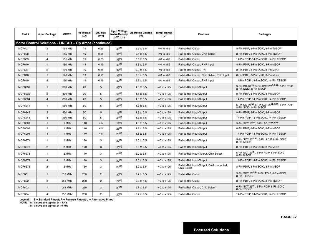
PAGE 57
lutions
Motor
MCP6 8-Pin PDIP, 8-Pin SOIC, 8-Pin TSSOP
MCP6 8-Pin PDIP, 8-Pin SOIC, 8-Pin TSSOP
MCP6 14-Pin PDIP, 14-Pin SOIC, 14-Pin TSSOP
MCP6 8-Pin PDIP, 8-Pin SOIC, 8-Pin MSOP
MCP6 8-Pin PDIP, 8-Pin SOIC, 8-Pin MSOP
MCP6 , PNP Input 8-Pin PDIP, 8-Pin SOIC, 8-Pin MSOP
MCP6 14-Pin PDIP, 14-Pin SOIC, 14-Pin TSSOP
MCP6 5-Pin SC-70(U), 5-Pin SOT-23(S,R,U), 8-Pin PDIP, 8-Pin SOIC, 8-Pin MSOP
MCP6 8-Pin PDIP, 8-Pin SOIC, 8-Pin MSOP
MCP6 14-Pin PDIP, 14-Pin SOIC, 14-Pin TSSOP
MCP6 5-Pin SC-70(U), 5-Pin SOT-23(S,R,U), 8-Pin PDIP, 8-Pin SOIC, 8-Pin MSOP
MCP6 8-Pin PDIP, 8-Pin SOIC, 8-Pin MSOP
MCP6 14-Pin PDIP, 14-Pin SOIC, 14-Pin TSSOP
MCP6 5-Pin SOT-23(U), 5-Pin SC-70(S,R,U)
MCP6 8-Pin PDIP, 8-Pin SOIC, 8-Pin MSOP
MCP6 14-Pin PDIP, 14-Pin SOIC, 14-Pin TSSOP
MCP6 5-Pin SOT-23(S,R), 8-Pin PDIP, 8-Pin SOIC, 8-Pin MSOP
MCP6 8-Pin PDIP, 8-Pin SOIC, 8-Pin MSOP
MCP6 elect 5-Pin SOT-23(S), 8-Pin PDIP, 8-Pin SOIC, 8-Pin MSOP
MCP6 14-Pin PDIP, 14-Pin SOIC, 14-Pin TSSOP
MCP6 onnected, 8-Pin PDIP, 8-Pin SOIC, 8-Pin MSOP
MCP6 5-Pin SOT-23(S,R),8-Pin PDIP, 8-Pin SOIC, 8-Pin TSSOP,
MCP6 8-Pin PDIP, 8-Pin SOIC, 8-Pin TSSOP
MCP6 6-Pin SOT-23(S), 8-Pin PDIP, 8-Pin SOIC, 8-Pin TSSOP
MCP6 14-Pin PDIP, 14-Pin SOIC, 14-Pin TSSOP
Pa Packages
LegeNOT
Focused So
Control Solutions - LINEAR – Op Amps (continued)
07 2 155 kHz 19 0.25 38(1) 2.5 to 5.5 -40 to +85 Rail-to-Rail Output
08 1 155 kHz 19 0.25 38(1) 2.5 to 5.5 -40 to +85 Rail-to-Rail Output, Chip Select
09 4 155 kHz 19 0.25 38(1) 2.5 to 5.5 -40 to +85 Rail-to-Rail Output
16 1 190 kHz 19 0.15 32(1) 2.3 to 5.5 -40 to +85 Rail-to-Rail Output, PNP Input
17 2 190 kHz 19 0.15 32(1) 2.3 to 5.5 -40 to +85 Rail-to-Rail Output, PNP
18 1 190 kHz 19 0.15 32(1) 2.3 to 5.5 -40 to +85 Rail-to-Rail Output, Chip Select
19 4 190 kHz 19 0.15 32(1) 2.3 to 5.5 -40 to +85 Rail-to-Rail Output, PNP Input
231 1 300 kHz 20 5 52(1) 1.8 to 5.5 -40 to +125 Rail-to-Rail Input/Output
232 2 300 kHz 20 5 52(1) 1.8 to 5.5 -40 to +125 Rail-to-Rail Input/Output
234 4 300 kHz 20 5 52(1) 1.8 to 5.5 -40 to +125 Rail-to-Rail Input/Output
241 1 550 kHz 50 5 45(1) 1.8 to 5.5 -40 to +125 Rail-to-Rail Input/Output
242 2 550 kHz 50 5 45(1) 1.8 to 5.5 -40 to +125 Rail-to-Rail Input/Output
244 4 550 kHz 50 5 45(1) 1.8 to 5.5 -40 to +125 Rail-to-Rail Input/Output
001 1 1 MHz 140 4.5 28(1) 1.8 to 5.5 -40 to +125 Rail-to-Rail Input/Output
002 2 1 MHz 140 4.5 28(1) 1.8 to 5.5 -40 to +125 Rail-to-Rail Input/Output
004 4 1 MHz 140 4.5 28(1) 1.8 to 5.5 -40 to +125 Rail-to-Rail Input/Output
271 1 2 MHz 170 3 20(1) 2.0 to 5.5 -40 to +125 Rail-to-Rail Input/Output
272 2 2 MHz 170 3 20(1) 2.0 to 5.5 -40 to +125 Rail-to-Rail Input/Output
273 1 2 MHz 170 3 20(1) 2.0 to 5.5 -40 to +125 Rail-to-Rail Input/Output, Chip S
274 4 2 MHz 170 3 20(1) 2.0 to 5.5 -40 to +125 Rail-to-Rail Input/Output
275 2 2 MHz 150 3 20(1) 2.0 to 5.5 -40 to +125 Rail-to-Rail Input/Output, Dual cChip Select
01 1 2.8 MHz 230 2 29(1) 2.7 to 5.5 -40 to +125 Rail-to-Rail Output
02 2 2.8 MHz 230 2 29(1) 2.7 to 5.5 -40 to +125 Rail-to-Rail Output
03 1 2.8 MHz 230 2 29(1) 2.7 to 5.5 -40 to +125 Rail-to-Rail Output, Chip Select
04 4 2.8 MHz 230 2 29(1) 2.7 to 5.5 -40 to +125 Rail-to-Rail Output
rt # # per Package GBWP IQ Typical (μA)
VOS Max (mV)
Input Voltage Noise Density
(nV/rtHz)
Operating Voltage (V)
Temp. Range (°C) Features
nd: S = Standard Pinout; R = Reverse Pinout; U = Alternative PinoutE 1: Values are typical at 1 kHz
2: Values are typical at 10 kHz

PAGE 58
Focused Solutions
Motor
MCP6 5-Pin SOT-23(S,R), 8-Pin PDIP, 8-Pin SOIC, 8-Pin MSOP
MCP6 8-Pin PDIP, 8-Pin SOIC, 8-Pin MSOP
MCP6 elect 6-Pin SOT-23(S,R), 8-Pin PDIP, 8-Pin SOIC, 8-Pin MSOP
MCP6 14-Pin PDIP, 14-Pin SOIC, 14-Pin TSSOP
MCP6 onnected, 8-Pin PDIP, 8-Pin SOIC, 8-Pin MSOP
MCP6 5-Pin SOT-23(S,R), 8-Pin PDIP, 8-Pin SOIC, 8-Pin MSOP
MCP6 8-Pin PDIP, 8-Pin SOIC, 8-Pin MSOP
MCP6 elect 6-Pin SOT-23(S), 8-Pin PDIP, 8-Pin SOIC, 8-Pin MSOP
MCP6 14-Pin PDIP, 14-Pin SOIC, 14-Pin TSSOP
MCP6 onnected, 8-Pin PDIP, 8-Pin SOIC, 8-Pin MSOP
MCP6 C VREF 8-Pin PDIP, 8-Pin SOIC, 8-Pin TSSOP
MCP6 8-Pin PDIP, 8-Pin SOIC, 8-Pin TSSOP
MCP6 elect 8-Pin PDIP, 8-Pin SOIC, 8-Pin TSSOP
MCP6 14-Pin PDIP, 14-Pin SOIC, 14-Pin TSSOP
Part es Packages
MotorTC913 8-Pin PDIP, 8-Pin SOIC
Pa Packages
LegeNOT
Control Solutions - LINEAR – Op Amps (continued)
281 1 5 MHz 445 3 16(1) 2.2 to 5.5 -40 to +125 Rail-to-Rail Input/Output
282 2 5 MHz 445 3 16(1) 2.2 to 5.5 -40 to +125 Rail-to-Rail Input/Output
283 1 5 MHz 445 3 16(1) 2.2 to 5.5 -40 to +125 Rail-to-Rail Input/Output, Chip S
284 4 5 MHz 445 3 16(1) 2.2 to 5.5 -40 to +125 Rail-to-Rail Input/Output
285 2 5 MHz 400 3 16(1) 2.2 to 5.5 -40 to +125 Rail-to-Rail Input/Output, Dual cChip Select
291 1 10 MHz 1000 3 8.7(2) 2.4 to 5.5 -40 to +125 Rail-to-Rail Input/Output
292 2 10 MHz 1000 3 8.7(2) 2.4 to 5.5 -40 to +125 Rail-to-Rail Input/Output
293 1 10 MHz 1000 3 8.7(2) 2.4 to 5.5 -40 to +125 Rail-to-Rail Input/Output, Chip S
294 4 10 MHz 1000 3 8.7(2) 2.4 to 5.5 -40 to +125 Rail-to-Rail Input/Output
295 2 10 MHz 1100 3 8.7(2) 2.4 to 5.5 -40 to +125 Rail-to-Rail Input/Output, Dual cChip Select
021 1 10 MHz 1000 0.5 8.7(2) 2.5 to 5.5 -40 to +125 Rail-to-Rail Input/Output, 1/2 VC
022 2 10 MHz 1000 0.5 8.7(2) 2.5 to 5.5 -40 to +125 Rail-to-Rail Input/Output
023 1 10 MHz 1000 0.5 8.7(2) 2.5 to 5.5 -40 to +125 Rail-to-Rail Input/Output, Chip S
024 4 10 MHz 1000 0.5 8.7(2) 2.5 to 5.5 -40 to +125 Rail-to-Rail Input/Output
# # per Package GBWP IQ MAX (mA) Typical VOS
(μV)VOS Drift Max
(μV/°C)Operating Voltage
(V) Temp. Range (°C) Featur
Control Solutions - LINEAR – High Precision Operational AmplifiersA/B 2 1.5 MHz 1.1 15 0.15/0.30 6.5 to 16 0 to 70 Single and Split Supply
rt # # per Package GBWP IQ Typical (μA)
VOS Max (mV)
Input Voltage Noise Density
(nV/rtHz)
Operating Voltage (V)
Temp. Range (°C) Features
nd: S = Standard Pinout; R = Reverse Pinout; U = Alternative PinoutE 1: Values are typical at 1 kHz
2: Values are typical at 10 kHz
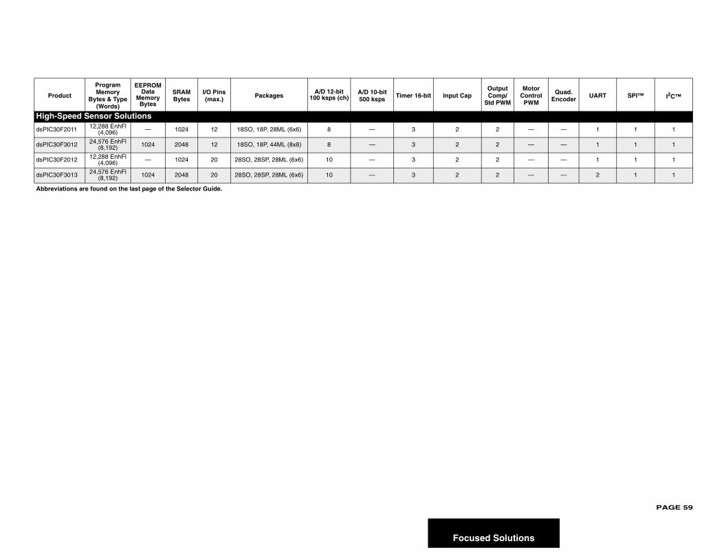
PAGE 59
lutions
Prot /M
Motor Control
PWM
Quad. Encoder UART SPI™ I2C™
High-S
dsPIC30 — — 1 1 1
dsPIC30 — — 1 1 1
dsPIC30 — — 1 1 1
dsPIC30 — — 2 1 1
Abbrevi
Focused So
duct
Program Memory
Bytes & Type (Words)
EEPROM Data
Memory Bytes
SRAM Bytes
I/O Pins (max.) Packages
A/D 12-bit 100 ksps (ch)
A/D 10-bit 500 ksps Timer 16-bit Input Cap
OutpuComp
Std PW
peed Sensor Solutions
F2011 12,288 EnhFl (4,096) — 1024 12 18SO, 18P, 28ML (6x6) 8 — 3 2 2
F3012 24,576 EnhFl (8,192) 1024 2048 12 18SO, 18P, 44ML (8x8) 8 — 3 2 2
F2012 12,288 EnhFl (4,096) — 1024 20 28SO, 28SP, 28ML (6x6) 10 — 3 2 2
F3013 24,576 EnhFl (8,192) 1024 2048 20 28SO, 28SP, 28ML (6x6) 10 — 3 2 2
ations are found on the last page of the Selector Guide.
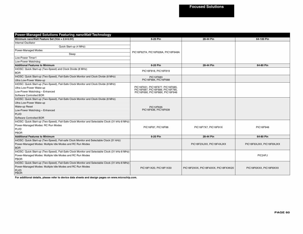
PAGE 60
Focused Solutions
PowerMinimum Pin 64-100 PinInternal
Power-M
Low-Pow
Low-Pow
Addition Pin 64-80 PinIntOSC:
BOR
IntOSC:
Ultra Low
IntOSC:
Ultra Low
Low-Pow
Software
IntOSC:
Ultra Low
Wake-up
Low-Pow
PLVD
Software
IntOSC:
IC16F91X PIC16F946Power-M
PLVD
PBOR
Addition Pin 64-80 PinIntOSC:
IC18F4XJXX PIC18F6XJXX, PIC18F8XJXXPower-M
BOR
IntOSC:
PIC24FJPower-M
PBOR
IntOSC:
XXX, PIC18FXXK20 PIC18F6XXX, PIC18F8XXXPower-M
PLVDPBOR
For add
-Managed Solutions Featuring nanoWatt Technology nanoWatt Feature Set (VDD = 2.0-5.5V) 6-20 Pin 28-44
Oscillator
PIC16F627A, PIC16F628A, PIC16F648A
Quick Start-up (4 MHz)
anaged Modes
Sleep
er Timer1
er Watchdog
al Features to Minimum 6-20 Pin 28-44 Quick Start-up (Two-Speed) and Clock Divide (8 MHz)
PIC16F818, PIC16F819
Quick Start-up (Two-Speed), Fail-Safe Clock Monitor and Clock Divide (8 MHz) PIC12F683PIC16F684, PIC16F688-Power Wake-up
Quick Start-up (Two-Speed), Fail-Safe Clock Monitor and Clock Divide (8 MHz)PIC16F631, PIC16F677, PIC16F685, PIC16F687, PIC16F689, PIC16F785, PIC16F690, PIC16F88X, PIC16F946
-Power Wake-up
er Watchdog – Enhanced
Controlled BOR
Quick Start-up (Two-Speed), Fail-Safe Clock Monitor and Clock Divide (8 MHz)
PIC12F635PIC16F636, PIC16F639
-Power Wake-up
Reset
er Watchdog – Enhanced
Controlled BOR
Quick Start-up (Two-Speed), Fail-Safe Clock Monitor and Selectable Clock (31 kHz-8 MHz)
PIC16F87, PIC16F88 PIC16F7X7, Panaged Modes: RC Run Modes
al Features to Minimum 6-20 Pin 28-44 Quick Start-up (Two-Speed), Fail-safe Clock Monitor and Selectable Clock (31 kHz)
PIC18F2XJXX, Panaged Modes: Multiple Idle Modes and RC Run Modes
Quick Start-up (Two-Speed), Fail-Safe Clock Monitor and Selectable Clock (31 kHz-8 MHz)
anaged Modes: Multiple Idle Modes and RC Run Modes
Quick Start-up (Two-Speed), Fail-Safe Clock Monitor and Selectable Clock (31 kHz-8 MHz)
PIC18F1X20, PIC18F1X30 PIC18F2XXX, PIC18F4anaged Modes: Multiple Idle Modes and RC Run Modes
itional details, please refer to device data sheets and design pages on www.microchip.com.
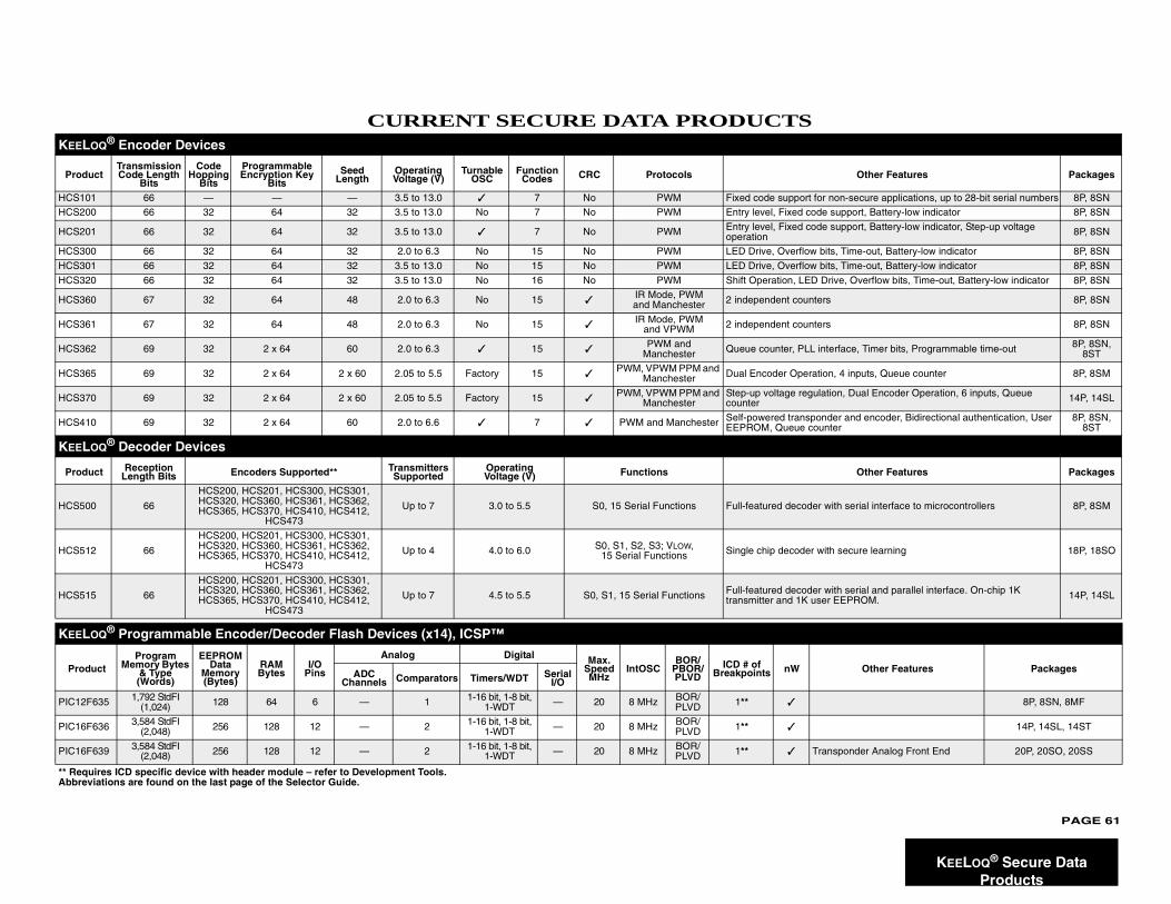
PAGE 61
KEELOQ® Secure Data Products
CURRENT SECURE DATA PRODUCTSKEELOQ® Encoder Devices
ProductTransmission Code Length
Bits
Code Hopping
Bits
Programmable Encryption Key
BitsSeed
Length Operating Voltage (V)
Turnable OSC
Function Codes CRC Protocols Other Features Packages
HCS101 66 — — — 3.5 to 13.0 ✓ 7 No PWM Fixed code support for non-secure applications, up to 28-bit serial numbers 8P, 8SN
HCS200 66 32 64 32 3.5 to 13.0 No 7 No PWM Entry level, Fixed code support, Battery-low indicator 8P, 8SN
HCS201 66 32 64 32 3.5 to 13.0 ✓ 7 No PWM Entry level, Fixed code support, Battery-low indicator, Step-up voltage operation 8P, 8SN
HCS300 66 32 64 32 2.0 to 6.3 No 15 No PWM LED Drive, Overflow bits, Time-out, Battery-low indicator 8P, 8SN
HCS301 66 32 64 32 3.5 to 13.0 No 15 No PWM LED Drive, Overflow bits, Time-out, Battery-low indicator 8P, 8SN
HCS320 66 32 64 32 3.5 to 13.0 No 16 No PWM Shift Operation, LED Drive, Overflow bits, Time-out, Battery-low indicator 8P, 8SN
HCS360 67 32 64 48 2.0 to 6.3 No 15 ✓IR Mode, PWM and Manchester 2 independent counters 8P, 8SN
HCS361 67 32 64 48 2.0 to 6.3 No 15 ✓IR Mode, PWM
and VPWM 2 independent counters 8P, 8SN
HCS362 69 32 2 x 64 60 2.0 to 6.3 ✓ 15 ✓PWM and
Manchester Queue counter, PLL interface, Timer bits, Programmable time-out 8P, 8SN, 8ST
HCS365 69 32 2 x 64 2 x 60 2.05 to 5.5 Factory 15 ✓PWM, VPWM PPM and
Manchester Dual Encoder Operation, 4 inputs, Queue counter 8P, 8SM
HCS370 69 32 2 x 64 2 x 60 2.05 to 5.5 Factory 15 ✓PWM, VPWM PPM and
ManchesterStep-up voltage regulation, Dual Encoder Operation, 6 inputs, Queue counter 14P, 14SL
HCS410 69 32 2 x 64 60 2.0 to 6.6 ✓ 7 ✓ PWM and Manchester Self-powered transponder and encoder, Bidirectional authentication, User EEPROM, Queue counter
8P, 8SN, 8ST
KEELOQ® Decoder Devices
Product Reception Length Bits Encoders Supported** Transmitters
SupportedOperating Voltage (V) Functions Other Features Packages
HCS500 66
HCS200, HCS201, HCS300, HCS301, HCS320, HCS360, HCS361, HCS362, HCS365, HCS370, HCS410, HCS412,
HCS473
Up to 7 3.0 to 5.5 S0, 15 Serial Functions Full-featured decoder with serial interface to microcontrollers 8P, 8SM
HCS512 66
HCS200, HCS201, HCS300, HCS301, HCS320, HCS360, HCS361, HCS362, HCS365, HCS370, HCS410, HCS412,
HCS473
Up to 4 4.0 to 6.0 S0, S1, S2, S3; VLOW, 15 Serial Functions Single chip decoder with secure learning 18P, 18SO
HCS515 66
HCS200, HCS201, HCS300, HCS301, HCS320, HCS360, HCS361, HCS362, HCS365, HCS370, HCS410, HCS412,
HCS473
Up to 7 4.5 to 5.5 S0, S1, 15 Serial Functions Full-featured decoder with serial and parallel interface. On-chip 1K transmitter and 1K user EEPROM. 14P, 14SL
KEELOQ® Programmable Encoder/Decoder Flash Devices (x14), ICSP™
ProductProgram
Memory Bytes & Type (Words)
EEPROM Data
Memory (Bytes)
RAM Bytes
I/O Pins
Analog Digital Max. Speed MHz
IntOSCBOR/
PBOR/PLVD
ICD # of Breakpoints nW Other Features PackagesADC
Channels Comparators Timers/WDT Serial I/O
PIC12F635 1,792 StdFI (1,024) 128 64 6 — 1 1-16 bit, 1-8 bit,
1-WDT — 20 8 MHz BOR/PLVD 1** ✓ 8P, 8SN, 8MF
PIC16F636 3,584 StdFI (2,048) 256 128 12 — 2 1-16 bit, 1-8 bit,
1-WDT — 20 8 MHz BOR/PLVD 1** ✓ 14P, 14SL, 14ST
PIC16F639 3,584 StdFI (2,048) 256 128 12 — 2 1-16 bit, 1-8 bit,
1-WDT — 20 8 MHz BOR/PLVD 1** ✓ Transponder Analog Front End 20P, 20SO, 20SS
** Requires ICD specific device with header module – refer to Development Tools.Abbreviations are found on the last page of the Selector Guide.
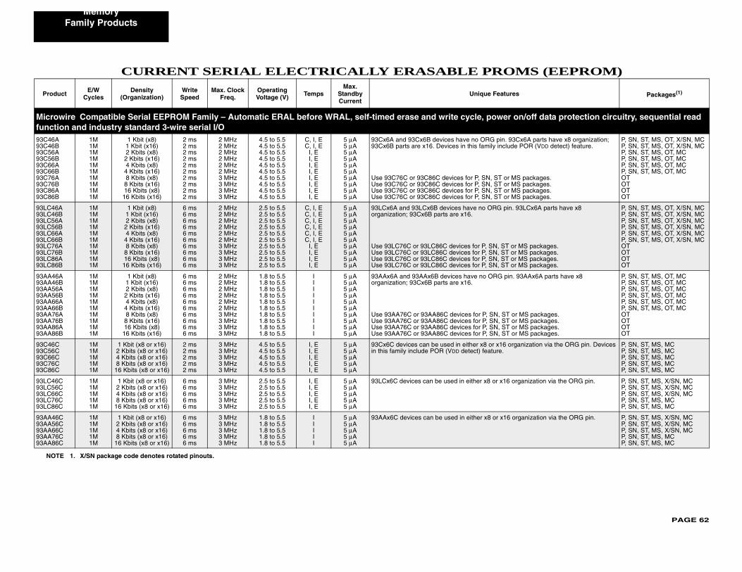
PAGE 62
Memory
MS (EEPROM)
Produ s Packages(1)
Microw n/off data protection circuitry, sequential read functi93C46A93C46B93C56A93C56B93C66A93C66B93C76A93C76B93C86A93C86B
Cx6A parts have x8 organization; POR (VDD detect) feature.
S packages.S packages.S packages.S packages.
P, SN, ST, MS, OT, X/SN, MCP, SN, ST, MS, OT, X/SN, MCP, SN, ST, MS, OT, MCP, SN, ST, MS, OT, MCP, SN, ST, MS, OT, MCP, SN, ST, MS, OT, MCOTOTOTOT
93LC46A93LC46B93LC56A93LC56B93LC66A93LC66B93LC76A93LC76B93LC86A93LC86B
93LCx6A parts have x8
MS packages. MS packages. MS packages. MS packages.
P, SN, ST, MS, OT, X/SN, MCP, SN, ST, MS, OT, X/SN, MCP, SN, ST, MS, OT, X/SN, MCP, SN, ST, MS, OT, X/SN, MCP, SN, ST, MS, OT, X/SN, MCP, SN, ST, MS, OT, X/SN, MCOTOTOTOT
93AA46A93AA46B93AA56A93AA56B93AA66A93AA66B93AA76A93AA76B93AA86A93AA86B
93AAx6A parts have x8
r MS packages.r MS packages.r MS packages.r MS packages.
P, SN, ST, MS, OT, MCP, SN, ST, MS, OT, MCP, SN, ST, MS, OT, MCP, SN, ST, MS, OT, MCP, SN, ST, MS, OT, MCP, SN, ST, MS, OT, MCOTOTOTOT
93C46C93C56C93C66C93C76C93C86C
anization via the ORG pin. Devices P, SN, ST, MS, MCP, SN, ST, MS, MCP, SN, ST, MS, MCP, SN, ST, MS, MCP, SN, ST, MS, MC
93LC46C93LC56C93LC66C93LC76C93LC86C
rganization via the ORG pin. P, SN, ST, MS, X/SN, MCP, SN, ST, MS, X/SN, MCP, SN, ST, MS, X/SN, MCP, SN, ST, MS, MCP, SN, ST, MS, MC
93AA46C93AA56C93AA66C93AA76C93AA86C
rganization via the ORG pin. P, SN, ST, MS, X/SN, MCP, SN, ST, MS, X/SN, MCP, SN, ST, MS, X/SN, MCP, SN, ST, MS, MCP, SN, ST, MS, MC
NOT
Family Products
CURRENT SERIAL ELECTRICALLY ERASABLE PRO
ct E/W Cycles
Density (Organization)
Write Speed
Max. Clock Freq.
Operating Voltage (V) Temps
Max. Standby Current
Unique Feature
ire Compatible Serial EEPROM Family – Automatic ERAL before WRAL, self-timed erase and write cycle, power oon and industry standard 3-wire serial I/O
1M1M1M1M1M1M1M1M1M1M
1 Kbit (x8)1 Kbit (x16)2 Kbits (x8)2 Kbits (x16)4 Kbits (x8)4 Kbits (x16)8 Kbits (x8)8 Kbits (x16)16 Kbits (x8)
16 Kbits (x16)
2 ms2 ms2 ms2 ms2 ms2 ms2 ms2 ms2 ms2 ms
2 MHz2 MHz2 MHz2 MHz2 MHz2 MHz3 MHz3 MHz3 MHz3 MHz
4.5 to 5.54.5 to 5.54.5 to 5.54.5 to 5.54.5 to 5.54.5 to 5.54.5 to 5.54.5 to 5.54.5 to 5.54.5 to 5.5
C, I, EC, I, E
I, EI, EI, EI, EI, EI, EI, EI, E
5 μA5 μA5 μA5 μA5 μA5 μA5 μA5 μA5 μA5 μA
93Cx6A and 93Cx6B devices have no ORG pin. 9393Cx6B parts are x16. Devices in this family include
Use 93C76C or 93C86C devices for P, SN, ST or MUse 93C76C or 93C86C devices for P, SN, ST or MUse 93C76C or 93C86C devices for P, SN, ST or MUse 93C76C or 93C86C devices for P, SN, ST or M
1M1M1M1M1M1M1M1M1M1M
1 Kbit (x8)1 Kbit (x16)2 Kbits (x8)2 Kbits (x16)4 Kbits (x8)4 Kbits (x16)8 Kbits (x8)8 Kbits (x16)16 Kbits (x8)
16 Kbits (x16)
6 ms6 ms6 ms6 ms6 ms6 ms6 ms6 ms6 ms6 ms
2 MHz2 MHz2 MHz2 MHz2 MHz2 MHz3 MHz3 MHz3 MHz3 MHz
2.5 to 5.52.5 to 5.52.5 to 5.52.5 to 5.52.5 to 5.52.5 to 5.52.5 to 5.52.5 to 5.52.5 to 5.52.5 to 5.5
C, I, EC, I, EC, I, EC, I, EC, I, EC, I, E
I, EI, EI, EI, E
5 μA5 μA5 μA5 μA5 μA5 μA5 μA5 μA5 μA5 μA
93LCx6A and 93LCx6B devices have no ORG pin. organization; 93Cx6B parts are x16.
Use 93LC76C or 93LC86C devices for P, SN, ST orUse 93LC76C or 93LC86C devices for P, SN, ST orUse 93LC76C or 93LC86C devices for P, SN, ST orUse 93LC76C or 93LC86C devices for P, SN, ST or
1M1M1M1M1M1M1M1M1M1M
1 Kbit (x8)1 Kbit (x16)2 Kbits (x8)2 Kbits (x16)4 Kbits (x8)4 Kbits (x16)8 Kbits (x8)8 Kbits (x16)16 Kbits (x8)
16 Kbits (x16)
6 ms6 ms6 ms6 ms6 ms6 ms6 ms6 ms6 ms6 ms
2 MHz2 MHz2 MHz2 MHz2 MHz2 MHz3 MHz3 MHz3 MHz3 MHz
1.8 to 5.51.8 to 5.51.8 to 5.51.8 to 5.51.8 to 5.51.8 to 5.51.8 to 5.51.8 to 5.51.8 to 5.51.8 to 5.5
IIIIIIIIII
5 μA5 μA5 μA5 μA5 μA5 μA5 μA5 μA5 μA5 μA
93AAx6A and 93AAx6B devices have no ORG pin.organization; 93Cx6B parts are x16.
Use 93AA76C or 93AA86C devices for P, SN, ST oUse 93AA76C or 93AA86C devices for P, SN, ST oUse 93AA76C or 93AA86C devices for P, SN, ST oUse 93AA76C or 93AA86C devices for P, SN, ST o
1M1M1M1M1M
1 Kbit (x8 or x16)2 Kbits (x8 or x16)4 Kbits (x8 or x16)8 Kbits (x8 or x16)
16 Kbits (x8 or x16)
2 ms2 ms2 ms2 ms2 ms
3 MHz3 MHz3 MHz3 MHz3 MHz
4.5 to 5.54.5 to 5.54.5 to 5.54.5 to 5.54.5 to 5.5
I, EI, EI, EI, EI, E
5 μA5 μA5 μA5 μA5 μA
93Cx6C devices can be used in either x8 or x16 orgin this family include POR (VDD detect) feature.
1M1M1M1M1M
1 Kbit (x8 or x16)2 Kbits (x8 or x16)4 Kbits (x8 or x16)8 Kbits (x8 or x16)
16 Kbits (x8 or x16)
6 ms6 ms6 ms6 ms6 ms
3 MHz3 MHz3 MHz3 MHz3 MHz
2.5 to 5.52.5 to 5.52.5 to 5.52.5 to 5.52.5 to 5.5
I, EI, EI, EI, EI, E
5 μA5 μA5 μA5 μA5 μA
93LCx6C devices can be used in either x8 or x16 o
1M1M1M1M1M
1 Kbit (x8 or x16)2 Kbits (x8 or x16)4 Kbits (x8 or x16)8 Kbits (x8 or x16)
16 Kbits (x8 or x16)
6 ms6 ms6 ms6 ms6 ms
3 MHz3 MHz3 MHz3 MHz3 MHz
1.8 to 5.51.8 to 5.51.8 to 5.51.8 to 5.51.8 to 5.5
IIIII
5 μA5 μA5 μA5 μA5 μA
93AAx6C devices can be used in either x8 or x16 o
E 1. X/SN package code denotes rotated pinouts.
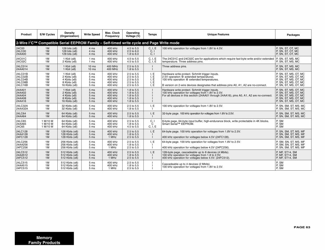
PAGE 63
Prod es Packages
2-Wire24C0024LC0024AA00
P, SN, ST, OT, MCP, SN, ST, OT, MCP, SN, ST, OT, MC
24C01C24C02C
require fast byte write and/or extended P, SN, ST, MS, MCP, SN, ST, MS, MC
24LC0124AA01
P, SN, ST, MS, MCP, SN, ST, MS, MC
24LC0124LC0224LC0424LC0824LC16 pins A0, A1, A2 are no-connect.
P, SN, ST, MS, OT, MCP, SN, ST, MS, OT, MCP, SN, ST, MS, OT, MCP, SN, ST, MS, OT, MCP, SN, ST, MS, OT, MC
24AA0124AA0224AA0424AA0824AA16
A16), pins A0, A1, A2 are no-connect.
P, SN, ST, MS, OT, MCP, SN, ST, MS, OT, MCP, SN, ST, MS, OT, MCP, SN, ST, MS, OT, MCP, SN, ST, MS, OT, MC
24LC3224AA32
P, SN, SM, ST, MS, MCP, SN, SM, ST, MS, MC
24LC6424AA64
to 2.5V. P, SN, SM, ST, MS, MCP, SN, SM, ST, MS, MC
24LC6524AA6524C65
lock, write protectable in 4K blocks. P, SMP, SMP, SM
24LC1224AA1224FC12
.8V to 2.5V.
8).
P, SN, SM, ST, MS, MFP, SN, SM, ST, MS, MFP, SN, SM, ST, MS, MF
24LC2524AA2524FC25
.8V to 2.5V.
6).
P, SM, SN, ST, MS, MFP, SM, SN, ST, MS, MFP, SN, SM, ST, MS, MF
24LC5124AA5124FC51
s).
2).
P, MF, ST14, SMP, MF, ST14, SMP, MF, ST14, SM
24LC5124AA5124FC51
P, SMP, SMP, SM
MemoryFamily Products
uct E/W Cycles Density (Organization) Write Speed Max. Clock
FrequencyOperating Voltage (V) Temps Unique Featur
I2C™ Compatible Serial EEPROM Family – Self-timed write cycle and Page Write mode1M1M1M
128 bits (x8)128 bits (x8)128 bits (x8)
4 ms4 ms4 ms
400 kHz400 kHz400 kHz
4.5 to 5.52.5 to 6.01.8 to 6.0
C, I, EC, IC, I
100 kHz operation for voltages from 1.8V to 4.5V.
1M1M
1 Kbit (x8)2 Kbits (x8)
1 ms1 ms
400 kHz400 kHz
4.5 to 5.54.5 to 5.5
C, I, EC, I, E
The 24C01C and 24C02C are for applications whichtemperature. Three address pins.
44
1M1M
1 Kbit (x8)1 Kbit (x8)
10 ms10 ms
400 MHz400 MHz
2.5 to 5.51.8 to 5.5
II
Three address pins.
BBBBB
1M1M1M1M1M
1 Kbit (x8)2 Kbits (x8) 4 Kbits (x8) 8 Kbits (x8)
16 Kbits (x8)
5 ms5 ms5 ms5 ms5 ms
400 kHz400 kHz400 kHz400 kHz400 kHz
2.5 to 5.52.5 to 5.52.5 to 5.52.5 to 5.52.5 to 5.5
I, EI, EI, EI, EI, E
Hardware write protect. Schmitt trigger inputs. 2.5V operation @ extended temperatures.100 kHz operation @ extended temperatures.
B version on 2-wire devices designates that address
1M1M1M1M1M
1 Kbit (x8)2 Kbits (x8) 4 Kbits (x8) 8 Kbits (x8)
16 Kbits (x8)
5 ms5 ms5 ms5 ms5 ms
400 kHz400 kHz400 kHz400 kHz400 kHz
1.8 to 5.51.8 to 5.51.8 to 5.51.8 to 5.51.8 to 5.5
IIIII
Hardware write protect. Schmitt trigger inputs. 100 kHz operation for voltages from 1.8V to 2.5V.For all devices in this section (24AA01 through 24A
AA
1M1M
32 Kbits (x8)32 Kbits (x8)
5 ms5 ms
400 kHz400 kHz
2.5 to 5.51.8 to 5.5
I, EI
100 kHz operation for voltages from 1.8V to 2.5V.
1M1M
64 Kbits (x8)64 Kbits (x8)
5 ms5 ms
400 kHz400 kHz
2.5 to 5.51.8 to 5.5
I, EI
32-byte page. 100 kHz operation for voltages from 1.8V
1 M/10 M1 M/10 M1 M/10 M
64 Kbits (x8)64 Kbits (x8)64 Kbits (x8)
5 ms5 ms5 ms
400 kHz400 kHz400 kHz
2.5 to 5.51.8 to 5.54.5 to 5.5
C, IC
C, I, E
8-byte page, 64-byte input buffer, high-endurance bSmart Serial™ EEPROM.
888
1M1M1M
128 Kbits (x8)128 Kbits (x8)128 Kbits (x8)
5 ms5 ms5 ms
400 kHz400 kHz1 MHz
2.5 to 5.51.8 to 5.52.5 to 5.5
I, EII
64-byte page. 100 kHz operation for voltages from 1
400 kHz operation for voltages below 4.5V (24FC12
666
1M1M1M
256 Kbits (x8)256 Kbits (x8)256 Kbits (x8)
5 ms5 ms5 ms
400 kHz400 kHz1 MHz
2.5 to 5.51.8 to 5.52.5 to 5.5
I, EII
64-byte page. 100 kHz operation for voltages from 1
400 kHz operation for voltages below 4.5V (24FC25
222
1M1M1M
512 Kbits (x8)512 Kbits (x8)512 Kbits (x8)
5 ms5 ms5 ms
400 kHz400 kHz1 MHz
2.5 to 5.51.8 to 5.52.5 to 5.5
I, EII
128-byte page, cascadeable up to 8 devices (4 Mbit100 kHz operation for voltages from 1.8 to 2.5V.400 kHz operation for voltages below 4.5V. (24FC51
555
1M1M1M
512 Kbits (x8)512 Kbits (x8)512 Kbits (x8)
5 ms5 ms5 ms
400 kHz400 kHz1 MHz
2.5 to 5.51.8 to 5.52.5 to 5.5
III
Cascadeable up to 4 devices (2 Mbits).100 kHz operation for voltages from 1.8V to 2.5V.
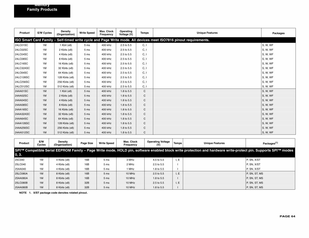
PAGE 64
Memory
Prod es Packages
ISO Sm24LC01S S, W, WF
24LC02S S, W, WF
24LC04S S, W, WF
24LC08S S, W, WF
24LC16S S, W, WF
24LC32A S, W, WF
24LC64S S, W, WF
24LC128 S, W, WF
24LC256 S, W, WF
24LC512 S, W, WF
24AA01S S, W, WF
24AA02S S, W, WF
24AA04S S, W, WF
24AA08S S, W, WF
24AA16S S, W, WF
24AA32A S, W, WF
24AA64S S, W, WF
24AA128 S, W, WF
24AA256 S. W, WF
24AA512 S, W, WF
Prod eatures Packages(1)
SPI™ dware write-protect pin. Supports SPI™ modes 0, 3.25C040 P, SN, X/ST
25LC040 P, SN, X/ST
25AA040 P, SN, X/ST
25LC080 P, SN, ST, MS
25AA080 P, SN, ST, MS
25LC080 P, SN, ST, MS
25AA080 P, SN, ST, MS
NOT
Family Products
uct E/W Cycles Density (Organization) Write Speed Max. Clock
FrequencyOperating Voltage (V) Temps Unique Featur
art Card Family – Self-timed write cycle and Page Write mode. All devices meet ISO7816 pinout requirements.C 1M 1 Kbit (x8) 5 ms 400 kHz 2.5 to 5.5 C, I
C 1M 2 Kbits (x8) 5 ms 400 kHz 2.5 to 5.5 C, I
C 1M 4 Kbits (x8) 5 ms 400 kHz 2.5 to 5.5 C, I
C 1M 8 Kbits (x8) 5 ms 400 kHz 2.5 to 5.5 C, I
C 1M 16 Kbits (x8) 5 ms 400 kHz 2.5 to 5.5 C, I
SC 1M 32 Kbits (x8) 5 ms 400 kHz 2.5 to 5.5 C, I
C 1M 64 Kbits (x8) 5 ms 400 kHz 2.5 to 5.5 C, I
SC 1M 128 Kbits (x8) 5 ms 400 kHz 2.5 to 5.5 C, I
SC 1M 256 Kbits (x8) 5 ms 400 kHz 2.5 to 5.5 C, I
SC 1M 512 Kbits (x8) 5 ms 400 kHz 2.5 to 5.5 C, I
C 1M 1 Kbit (x8) 5 ms 400 kHz 1.8 to 5.5 C
C 1M 2 Kbits (x8) 5 ms 400 kHz 1.8 to 5.5 C
C 1M 4 Kbits (x8) 5 ms 400 kHz 1.8 to 5.5 C
C 1M 8 Kbits (x8) 5 ms 400 kHz 1.8 to 5.5 C
C 1M 16 Kbits (x8) 5 ms 400 kHz 1.8 to 5.5 C
SC 1M 32 Kbits (x8) 5 ms 400 kHz 1.8 to 5.5 C
C 1M 64 Kbits (x8) 5 ms 400 kHz 1.8 to 5.5 C
SC 1M 128 Kbits (x8) 5 ms 400 kHz 1.8 to 5.5 C
SC 1M 256 Kbits (x8) 5 ms 400 kHz 1.8 to 5.5 C
SC 1M 512 Kbits (x8) 5 ms 400 kHz 1.8 to 5.5 C
uct E/W Cycles
Density (Organization) Page Size Write Speed Max. Clock
FrequencyOperating Voltage
(V) Temps Unique F
Compatible Serial EEPROM Family – Page Write mode, HOLD pin, software enabled block write protection and har
1M 4 Kbits (x8) 16B 5 ms 3 MHz 4.5 to 5.5 I, E
1M 4 Kbits (x8) 16B 5 ms 2 MHz 2.5 to 5.5 I
1M 4 Kbits (x8) 16B 5 ms 1 MHz 1.8 to 5.5 I
A 1M 8 Kbits (x8) 16B 5 ms 10 MHz 2.5 to 5.5 I, E
A 1M 8 Kbits (x8) 16B 5 ms 10 MHz 1.8 to 5.5 I
B 1M 8 Kbits (x8) 32B 5 ms 10 MHz 2.5 to 5.5 I, E
B 1M 8 Kbits (x8) 32B 5 ms 10 MHz 1.8 to 5.5 I
E 1. X/ST package code denotes rotated pinout.
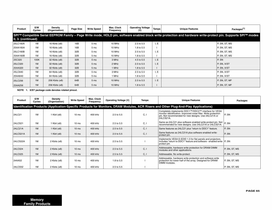
PAGE 65
SPI™ dware write-protect pin. Supports SPI™ modes 0, 3. (c25LC16 P, SN, ST, MS
25AA16 P, SN, ST, MS
25LC16 P, SN, ST, MS
25AA16 P, SN, ST, MS
25C320 P, SN
25LC32 P, SN, X/ST
25AA32 P, SN, X/ST
25LC64 P, SN, X/ST
25AA64 P, SN, X/ST
25LC25 P, SN, ST, MF
25AA25 P, SN, ST, MF
Prod Features Packages
Identi y Applications)
24LC21
1™/DDC2™ interface for VESA ed noise filter. Write protection w designs. Use 24LC21A or P, SN
24LCS2 re enabled write-protect pin. Not s. Use 24LC21A or 24LCS21A. P, SN
24LC21 s “return to DDC1” feature. P, SN
24LCS2 lus software enabled write- P, SN
24LCS23 for flat panels and projectors. ture and software - enabled write P, SN
24LC02 protection for DRAM DIMM ns. P, SN, ST, MS
24LC02 t. P, SN, ST, MS
24AA52protection and software write array. Designed for DRAM P, SN, ST, MS
24LCS5 P, SN, ST, MS
Prod eatures Packages(1)
NOT
MemoryFamily Products
Compatible Serial EEPROM Family – Page Write mode, HOLD pin, software enabled block write protection and harontinued)
0A 1M 16 Kbits (x8) 16B 5 ms 10 MHz 2.5 to 5.5 I, E
0A 1M 16 Kbits (x8) 16B 5 ms 10 MHz 1.8 to 5.5 I
0B 1M 16 Kbits (x8) 32B 5 ms 10 MHz 2.5 to 5.5 I, E
0B 1M 16 Kbits (x8) 32B 5 ms 10 MHz 1.8 to 5.5 I
100K 32 Kbits (x8) 32B 5 ms 3 MHz 4.5 to 5.5 I, E
0 1M 32 Kbits (x8) 32B 5 ms 2 MHz 2.5 to 5.5 I, E
0 1M 32 Kbits (x8) 32B 5 ms 1 MHz 1.8 to 5.5 I
0 1M 64 Kbits (x8) 32B 5 ms 3 MHz 2.5 to 5.5 I, E
0 1M 64 Kbits (x8) 32B 5 ms 1 MHz 1.8 to 5.5 I
6 1M 256 Kbits (x8) 64B 5 ms 10 MHz 2.5 to 5.5 I. E
6 1M 256 Kbits (x8) 64B 5 ms 10 MHz 1.8 to 5.5 I
uct E/W Cycles
Density (Organization) Write Speed Max. Clock
Frequency Operating Voltage (V) Temps Unique
fication Products (Application-Specific Products for Monitors, DRAM Modules, ACR Risers and Other Plug-And-Pla
1M 1 Kbit (x8) 10 ms 400 kHz 2.5 to 5.5 C, I
Completely implements DDCmonitor identification. Improvpin. Not recommended for ne24LCS21A.
1 1M 1 Kbit (x8) 10 ms 400 kHz 2.5 to 5.5 C, I Same as 24LC21 plus softwarecommended for new design
A 1M 1 Kbit (x8) 10 ms 400 kHz 2.5 to 5.5 C, I Same features as 24LC21 plu
1A 1M 1 Kbit (x8) 10 ms 400 kHz 2.5 to 5.5 C, I Same features as 24LC21A pprotect pin.
2A 1M 2 Kbits (x8) 10 ms 400 kHz 2.5 to 5.5 IImplements VESA E-EDID 1.Includes “return to DDC1” feaprotect pin.
4 1M 2 Kbits (x8) 10 ms 400 kHz 2.5 to 5.5 C, I Addressable, hardware write modules and other applicatio
5 1M 2 Kbits (x8) 10 ms 400 kHz 2.5 to 5.5 C, I Addressable. No write-protec
1M 2 Kbits (x8) 10 ms 400 kHz 1.8 to 5.5 IAddressable, hardware write protection for lower half of theDIMM modules.
2 1M 2 Kbits (x8) 10 ms 400 kHz 2.5 to 5.5 I
uct E/W Cycles
Density (Organization) Page Size Write Speed Max. Clock
FrequencyOperating Voltage
(V) Temps Unique F
E 1. X/ST package code denotes rotated pinout.
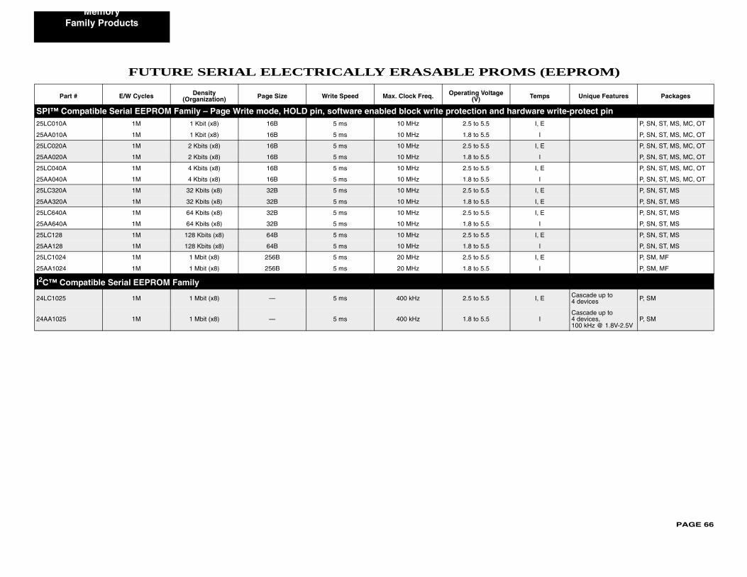
PAGE 66
Memory
S (EEPROM)
Temps Unique Features Packages
SPI™ dware write-protect pin25LC010 I, E P, SN, ST, MS, MC, OT
25AA010 I P, SN, ST, MS, MC, OT
25LC020 I, E P, SN, ST, MS, MC, OT
25AA020 I P, SN, ST, MS, MC, OT
25LC040 I, E P, SN, ST, MS, MC, OT
25AA040 I P, SN, ST, MS, MC, OT
25LC320 I, E P, SN, ST, MS
25AA320 I, E P, SN, ST, MS
25LC640 I, E P, SN, ST, MS
25AA640 I P, SN, ST, MS
25LC128 I, E P, SN, ST, MS
25AA128 I P, SN, ST, MS
25LC102 I, E P, SM, MF
25AA102 I P, SM, MF
I2C™
24LC102 I, E Cascade up to 4 devices P, SM
24AA102 ICascade up to 4 devices, 100 kHz @ 1.8V-2.5V
P, SM
Family Products
FUTURE SERIAL ELECTRICALLY ERASABLE PROM
Part # E/W Cycles Density (Organization) Page Size Write Speed Max. Clock Freq. Operating Voltage
(V)
Compatible Serial EEPROM Family – Page Write mode, HOLD pin, software enabled block write protection and harA 1M 1 Kbit (x8) 16B 5 ms 10 MHz 2.5 to 5.5
A 1M 1 Kbit (x8) 16B 5 ms 10 MHz 1.8 to 5.5
A 1M 2 Kbits (x8) 16B 5 ms 10 MHz 2.5 to 5.5
A 1M 2 Kbits (x8) 16B 5 ms 10 MHz 1.8 to 5.5
A 1M 4 Kbits (x8) 16B 5 ms 10 MHz 2.5 to 5.5
A 1M 4 Kbits (x8) 16B 5 ms 10 MHz 1.8 to 5.5
A 1M 32 Kbits (x8) 32B 5 ms 10 MHz 2.5 to 5.5
A 1M 32 Kbits (x8) 32B 5 ms 10 MHz 1.8 to 5.5
A 1M 64 Kbits (x8) 32B 5 ms 10 MHz 2.5 to 5.5
A 1M 64 Kbits (x8) 32B 5 ms 10 MHz 1.8 to 5.5
1M 128 Kbits (x8) 64B 5 ms 10 MHz 2.5 to 5.5
1M 128 Kbits (x8) 64B 5 ms 10 MHz 1.8 to 5.5
4 1M 1 Mbit (x8) 256B 5 ms 20 MHz 2.5 to 5.5
4 1M 1 Mbit (x8) 256B 5 ms 20 MHz 1.8 to 5.5
Compatible Serial EEPROM Family
5 1M 1 Mbit (x8) — 5 ms 400 kHz 2.5 to 5.5
5 1M 1 Mbit (x8) — 5 ms 400 kHz 1.8 to 5.5
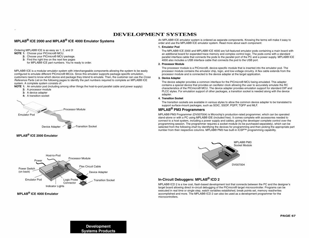
PAGE 67
..
MPLABHow DOrderingNOTE 1:
2:3:
A ComMPLAB®configurecustomeReferencsystem. ANOTE 1:
2:3:4:
s separate components. Knowing the terms will make it easy to m. Read more about each component:
000 are full-featured emulator pods containing a main board with ory and complex control logic. The pods come with a standard s to the parallel port of the PC and a power supply. MPLAB® ICE t connects the pod to the USB port.
e-specific module that is inserted into the emulator pod. The , logic, and low-voltage circuitry. A flex cable extends from the
evice adapter at the target application.
rface for the PICmicro® MCU being emulated. This adapter cillator clock allowing the user to accurately emulate the RC
device adapter provides emulation support for standard DIP and packages, a transition socket is needed along with the device
s styles to allow the common device adapter to be translated to OIC, SSOP, PQFP, TQFP and MLF.
rochip’s production-rated programmer, which can be operated ncluded free). It comes complete with accessories needed to pply and cables, giving the developer complete control over the s a socket module (to be purchased separately), which can be the devices for programming and then picking the appropriate part ® PM3 has built-in ICSP™ programming capability.
2lopment tool that connects between the PC and the designer’s of the PICmicro® target microcontroller. Programs can be bles established, break points set, memory read/writes an also be used as a development programmer for the
Emula
MPLA
Powe(on b
MPLA
MPLAB® PM3
DV007004
Socket Module
DevelopmentSystems Products
® ICE 2000 and MPLAB® ICE 4000 Emulator Systemso I Order MPLAB® ICE? MPLAB® ICE is as easy as 1, 2, and 3!
Choose your PICmicro® MCU.Choose your PICmicro® MCU package.Find the right line on the next few pages for MPLAB® ICE part numbers. You’re ready to order.
plete MPLAB® ICE System ICE is a modular emulator system with interchangeable components allowing the system to be easily d to emulate different PICmicro® MCUs. Since this emulator supports package-specific emulation,
rs need to know which device and package they intend to emulate. Then, the customer can use the Cross e Parts List on the following pages to identify the part numbers required to complete an MPLAB® ICE complete system consists of: An emulator pod (including among other things the host-to-pod parallel cable and power supply)A processor moduleA device adapter A transition socket
An MPLAB® ICE emulator system is ordered aorder and use the MPLAB® ICE emulator syste
1. Emulator PodThe MPLAB® ICE 2000 and MPLAB® ICE 4an additional board for expanded trace memparallel interface cable that connects the pod4000 also includes a USB interface cable tha
2. Processor ModuleThe processor module is a PICmicro®, devicprocessor module contains the emulator chipprocessor module and is connected to the d
3. Device AdapterThe device adapter provides a common intecontains a special device that provides an oscharacteristics of the PICmicro® MCU. The PLCC styles. For emulation support of otheradapter.
4. Transition SocketThe transition sockets are available in variousupport surface-mount packages, such as S
MPLAB® PM3 ProgrammersMPLAB® PM3 Programmer (DV007004) is Micstand-alone or with a PC using MPLAB® IDE (iconnect to a host system, including a power suprogramming session. The programmer requireselected from the following chart by identifying number from their respective columns. MPLAB
In-Circuit Debuggers: MPLAB® ICDMPLAB® ICD 2 is a low cost, flash-based devetarget board allowing direct in-circuit debuggingexecuted in real time or single step, watch variaaccomplished and more. The MPLAB® ICD 2 cmicrocontrollers.
DEVELOPMENT SYSTEMS
tor Pod
Processor Module
Device Adapter Transition Socket
B® ICE 2000 Emulator
Device Adapter
Transition Socket
Processor Module
Emulator Pod
Indicator Lights
Logic ProbeConnector
r Switchack)
Power
Host-to-Pod
Flex Circuit Cable
B® ICE 4000 Emulator
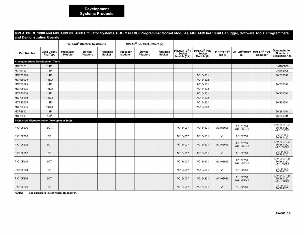
PAGE 68
MPLA ircuit Debugger, Software Tools, Programmers and D
Part PICSTART® Plus (5)
MPLAB® ICD 2 (6)
MPLAB® CXX Compiler
Demonstration Boards or
Evaluation Kits
Analog
MCP212 DM163008
MCP215 DM163008
MCP250 DV250501
MCP250
MCP250 DV250501
MCP250
MCP250 DV250501
MCP250
MCP250 DV250501
MCP250
MCP251 DV251001
MCP251 DV251001
PICmicr
PIC10F2 AC163020 AC162059+XLT06SOT
DV164101 or DV164120
+AC163020
PIC10F2 ✓ AC162059 DV164101, DV164120
PIC10F2 AC163020 AC162059+XLT06SOT
DV164101 or DV164120
+AC163020
PIC10F2 ✓ AC162059 DV164101, DV164120
PIC10F2 AC163020 AC162059+XLT06SOT
DV164101 or DV164120
+AC163020
PIC10F2 ✓ AC162059 DV164101, DV164120
PIC10F2 AC163020 AC162059+XLT06SOT
DV164101 or DV164120
+AC163020
PIC10F2 ✓ AC162059 DV164101, DV164120
NOTE:
DevelopmentSystems Products
B® ICE 2000 and MPLAB® ICE 4000 Emulator Systems, PRO MATE® II Programmer Socket Modules, MPLAB® In-Cemonstration Boards
MPLAB® ICE 2000 System (1) MPLAB® ICE 4000 System (2)
Number Lead Count/Pkg Type
Processor Module
Device Adapters
Transition Socket
Processor Module
Device Adapters
Transition Socket
PRO MATE® II Socket
Module (3,4)
MPLAB® PM3Socket
Module (8)
Interface Development Tools
0 14P
0 18P
20 14P AC164301
20 14SO AC164302
25 14P AC164301
25 14SO AC164302
50 14P AC164301
50 14SO AC164302
55 14P AC164301
55 14SO AC164302
0 18P
5 18P
o® Microcontroller Development Tools
00 6OT AC164037 AC164321
00 8P AC164037 AC164301
02 6OT AC164037 AC164321
02 8P AC164037 AC164301
04 6OT AC164037 AC164321
04 8P AC164037 AC164301
06 6OT AC164037 AC164321
06 8P AC164037 AC164301
See complete list of notes on page 94.
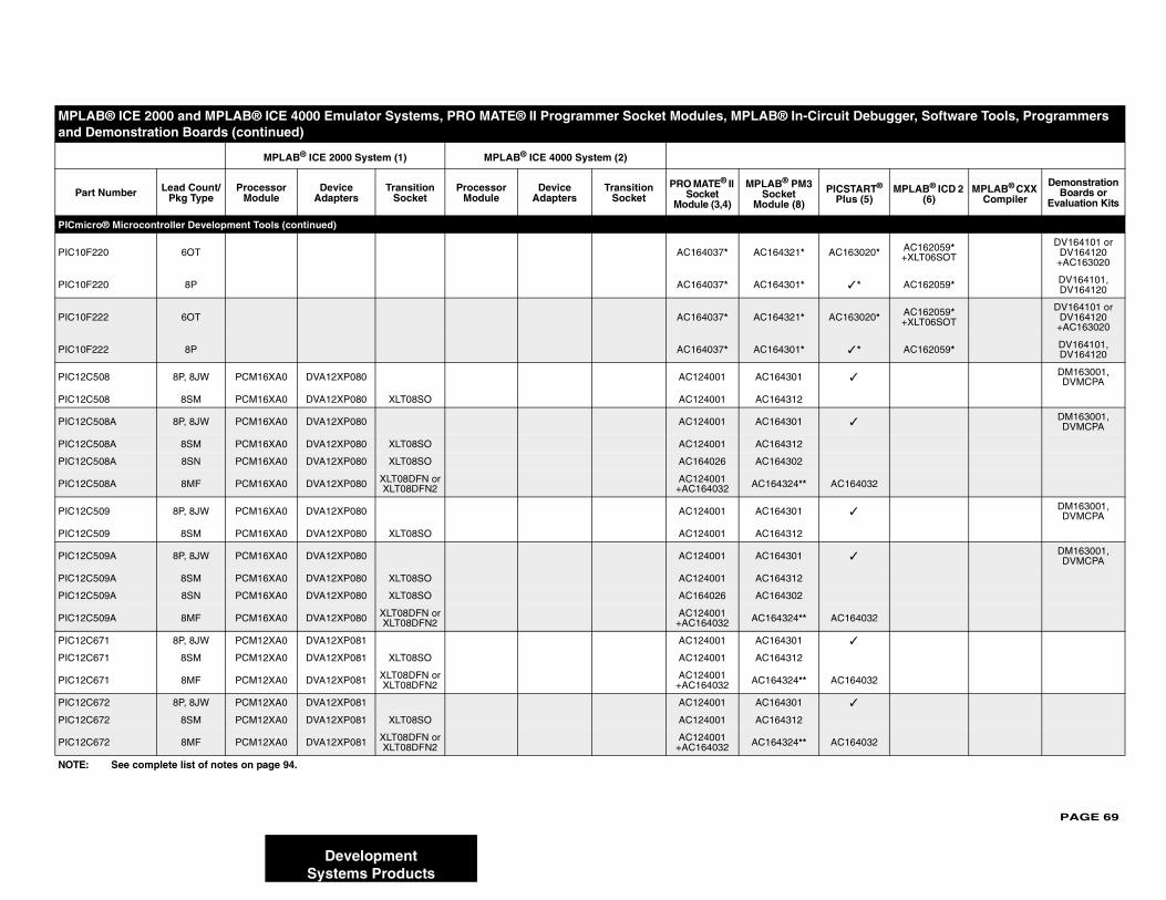
PAGE 69
PICmicr
PIC10F2 AC163020* AC162059*+XLT06SOT
DV164101 or DV164120
+AC163020
PIC10F2 ✓ * AC162059* DV164101, DV164120
PIC10F2 AC163020* AC162059*+XLT06SOT
DV164101 or DV164120
+AC163020
PIC10F2 ✓ * AC162059* DV164101, DV164120
PIC12C ✓DM163001, DVMCPA
PIC12C
PIC12C ✓DM163001, DVMCPA
PIC12C
PIC12C
PIC12C AC164032
PIC12C ✓DM163001, DVMCPA
PIC12C
PIC12C ✓DM163001, DVMCPA
PIC12C
PIC12C
PIC12C AC164032
PIC12C ✓
PIC12C
PIC12C AC164032
PIC12C ✓
PIC12C
PIC12C AC164032
MPLA ircuit Debugger, Software Tools, Programmers and D
Part PICSTART® Plus (5)
MPLAB® ICD 2 (6)
MPLAB® CXX Compiler
Demonstration Boards or
Evaluation Kits
NOTE:
DevelopmentSystems Products
o® Microcontroller Development Tools (continued)
20 6OT AC164037* AC164321*
20 8P AC164037* AC164301*
22 6OT AC164037* AC164321*
22 8P AC164037* AC164301*
508 8P, 8JW PCM16XA0 DVA12XP080 AC124001 AC164301
508 8SM PCM16XA0 DVA12XP080 XLT08SO AC124001 AC164312
508A 8P, 8JW PCM16XA0 DVA12XP080 AC124001 AC164301
508A 8SM PCM16XA0 DVA12XP080 XLT08SO AC124001 AC164312
508A 8SN PCM16XA0 DVA12XP080 XLT08SO AC164026 AC164302
508A 8MF PCM16XA0 DVA12XP080 XLT08DFN orXLT08DFN2
AC124001+AC164032 AC164324**
509 8P, 8JW PCM16XA0 DVA12XP080 AC124001 AC164301
509 8SM PCM16XA0 DVA12XP080 XLT08SO AC124001 AC164312
509A 8P, 8JW PCM16XA0 DVA12XP080 AC124001 AC164301
509A 8SM PCM16XA0 DVA12XP080 XLT08SO AC124001 AC164312
509A 8SN PCM16XA0 DVA12XP080 XLT08SO AC164026 AC164302
509A 8MF PCM16XA0 DVA12XP080 XLT08DFN orXLT08DFN2
AC124001+AC164032 AC164324**
671 8P, 8JW PCM12XA0 DVA12XP081 AC124001 AC164301
671 8SM PCM12XA0 DVA12XP081 XLT08SO AC124001 AC164312
671 8MF PCM12XA0 DVA12XP081 XLT08DFN orXLT08DFN2
AC124001+AC164032 AC164324**
672 8P, 8JW PCM12XA0 DVA12XP081 AC124001 AC164301
672 8SM PCM12XA0 DVA12XP081 XLT08SO AC124001 AC164312
672 8MF PCM12XA0 DVA12XP081 XLT08DFN orXLT08DFN2
AC124001+AC164032 AC164324**
B® ICE 2000 and MPLAB® ICE 4000 Emulator Systems, PRO MATE® II Programmer Socket Modules, MPLAB® In-Cemonstration Boards (continued)
MPLAB® ICE 2000 System (1) MPLAB® ICE 4000 System (2)
Number Lead Count/Pkg Type
Processor Module
Device Adapters
Transition Socket
Processor Module
Device Adapters
Transition Socket
PRO MATE® II Socket
Module (3,4)
MPLAB® PM3Socket
Module (8)
See complete list of notes on page 94.
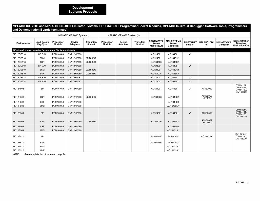
PAGE 70
PICmicr
PIC12CE ✓
PIC12CE
PIC12CE
PIC12CE ✓
PIC12CE
PIC12CE
PIC12CE ✓
PIC12CE ✓
PIC12F5 ✓ AC162059
DV164101, DM163014, DV164120, DM163029
PIC12F5 AC162059+XLT08SO
PIC12F5
PIC12F5
PIC12F5 ✓ AC162059
DM163014, DV164101, DV164120,DM163029
PIC12F5 AC162059+XLT08SO
PIC12F5
PIC12F5
PIC12F5 AC162070*DV164101*, DV164120,DM163029
PIC12F5
PIC12F5
PIC12F5
MPLA ircuit Debugger, Software Tools, Programmers and D
Part PICSTART® Plus (5)
MPLAB® ICD 2 (6)
MPLAB® CXX Compiler
Demonstration Boards or
Evaluation Kits
NOTE:
DevelopmentSystems Products
o® Microcontroller Development Tools (continued)
518 8P, 8JW PCM16XA0 DVA12XP080 AC124001 AC164301
518 8SM PCM16XA0 DVA12XP080 XLT08SO AC124001 AC164312
518 8SN PCM16XA0 DVA12XP080 XLT08SO AC164026 AC164302
519 8P, 8JW PCM16XA0 DVA12XP080 AC124001 AC164301
519 8SM PCM16XA0 DVA12XP080 XLT08SO AC124001 AC164312
519 8SN PCM16XA0 DVA12XP080 XLT08SO AC164026 AC164302
673 8P, 8JW PCM12XA0 DVA12XP081 AC124001 AC164301
674 8P, 8JW PCM12XA0 DVA12XP081 AC124001 AC164301
08 8P PCM16XA0 DVA12XP080 AC124001 AC164301
08 8SN PCM16XA0 DVA12XP080 XLT08SO AC164026 AC164302
08 8ST PCM16XA0 DVA12XP080 AC164306
08 8MS PCM16XA0 DVA12XP080 AC164325**
09 8P PCM16XA0 DVA12XP080 AC124001 AC164301
09 8SN PCM16XA0 DVA12XP080 XLT08SO AC164026 AC164302
09 8ST PCM16XA0 DVA12XP080 AC164306
09 8MS PCM16XA0 DVA12XP080 AC164325**
10 8P AC124001* AC164301*
10 8SN AC164026* AC164302*
10 8MS AC164325**
10 8MF AC164324**
B® ICE 2000 and MPLAB® ICE 4000 Emulator Systems, PRO MATE® II Programmer Socket Modules, MPLAB® In-Cemonstration Boards (continued)
MPLAB® ICE 2000 System (1) MPLAB® ICE 4000 System (2)
Number Lead Count/Pkg Type
Processor Module
Device Adapters
Transition Socket
Processor Module
Device Adapters
Transition Socket
PRO MATE® II Socket
Module (3,4)
MPLAB® PM3Socket
Module (8)
See complete list of notes on page 94.
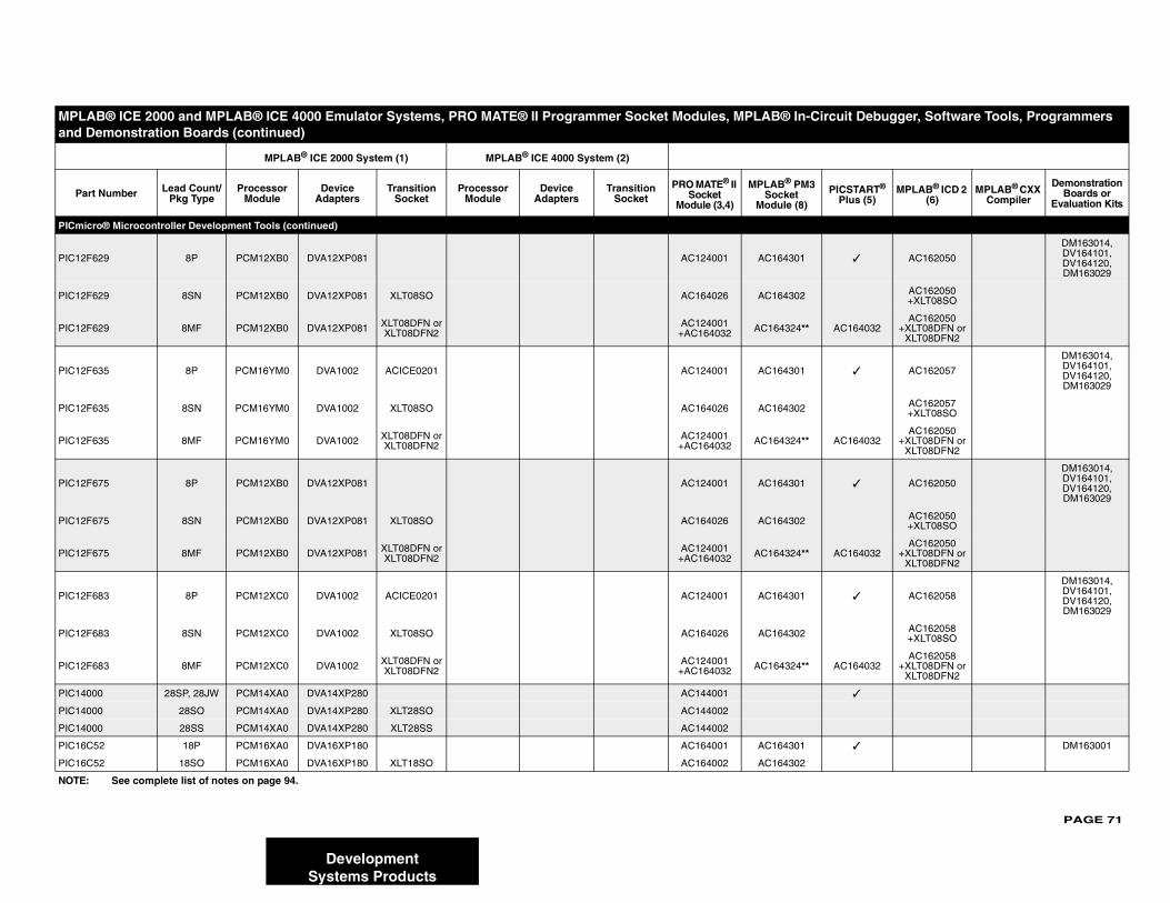
PAGE 71
PICmicr
PIC12F6 ✓ AC162050
DM163014, DV164101, DV164120,DM163029
PIC12F6 AC162050+XLT08SO
PIC12F6 AC164032AC162050
+XLT08DFN orXLT08DFN2
PIC12F6 ✓ AC162057
DM163014, DV164101, DV164120,DM163029
PIC12F6 AC162057+XLT08SO
PIC12F6 AC164032AC162050
+XLT08DFN orXLT08DFN2
PIC12F6 ✓ AC162050
DM163014, DV164101, DV164120,DM163029
PIC12F6 AC162050+XLT08SO
PIC12F6 AC164032AC162050
+XLT08DFN orXLT08DFN2
PIC12F6 ✓ AC162058
DM163014, DV164101, DV164120,DM163029
PIC12F6 AC162058+XLT08SO
PIC12F6 AC164032AC162058
+XLT08DFN orXLT08DFN2
PIC1400 ✓
PIC1400
PIC1400
PIC16C ✓ DM163001
PIC16C
MPLA ircuit Debugger, Software Tools, Programmers and D
Part PICSTART® Plus (5)
MPLAB® ICD 2 (6)
MPLAB® CXX Compiler
Demonstration Boards or
Evaluation Kits
NOTE:
DevelopmentSystems Products
o® Microcontroller Development Tools (continued)
29 8P PCM12XB0 DVA12XP081 AC124001 AC164301
29 8SN PCM12XB0 DVA12XP081 XLT08SO AC164026 AC164302
29 8MF PCM12XB0 DVA12XP081 XLT08DFN orXLT08DFN2
AC124001+AC164032 AC164324**
35 8P PCM16YM0 DVA1002 ACICE0201 AC124001 AC164301
35 8SN PCM16YM0 DVA1002 XLT08SO AC164026 AC164302
35 8MF PCM16YM0 DVA1002 XLT08DFN orXLT08DFN2
AC124001+AC164032 AC164324**
75 8P PCM12XB0 DVA12XP081 AC124001 AC164301
75 8SN PCM12XB0 DVA12XP081 XLT08SO AC164026 AC164302
75 8MF PCM12XB0 DVA12XP081 XLT08DFN orXLT08DFN2
AC124001+AC164032 AC164324**
83 8P PCM12XC0 DVA1002 ACICE0201 AC124001 AC164301
83 8SN PCM12XC0 DVA1002 XLT08SO AC164026 AC164302
83 8MF PCM12XC0 DVA1002 XLT08DFN orXLT08DFN2
AC124001 +AC164032 AC164324**
0 28SP, 28JW PCM14XA0 DVA14XP280 AC144001
0 28SO PCM14XA0 DVA14XP280 XLT28SO AC144002
0 28SS PCM14XA0 DVA14XP280 XLT28SS AC144002
52 18P PCM16XA0 DVA16XP180 AC164001 AC164301
52 18SO PCM16XA0 DVA16XP180 XLT18SO AC164002 AC164302
B® ICE 2000 and MPLAB® ICE 4000 Emulator Systems, PRO MATE® II Programmer Socket Modules, MPLAB® In-Cemonstration Boards (continued)
MPLAB® ICE 2000 System (1) MPLAB® ICE 4000 System (2)
Number Lead Count/Pkg Type
Processor Module
Device Adapters
Transition Socket
Processor Module
Device Adapters
Transition Socket
PRO MATE® II Socket
Module (3,4)
MPLAB® PM3Socket
Module (8)
See complete list of notes on page 94.
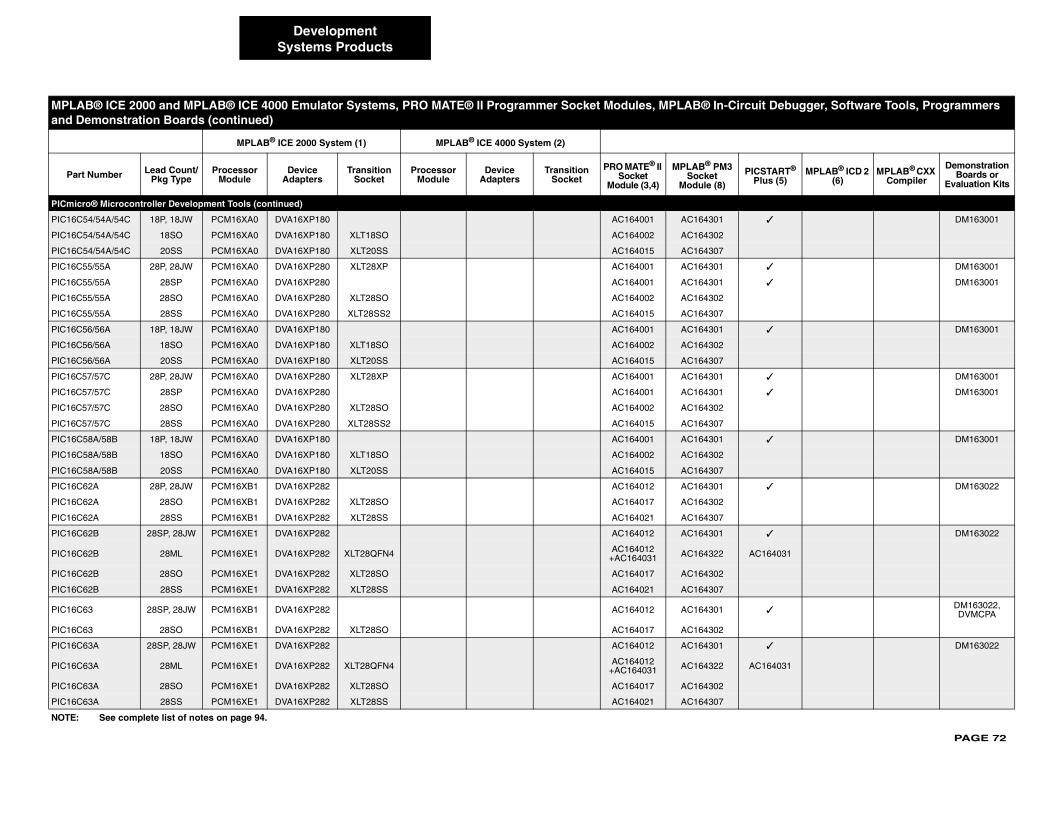
PAGE 72
PICmicr
PIC16C5 ✓ DM163001
PIC16C5
PIC16C5
PIC16C5 ✓ DM163001
PIC16C5 ✓ DM163001
PIC16C5
PIC16C5
PIC16C5 ✓ DM163001
PIC16C5
PIC16C5
PIC16C5 ✓ DM163001
PIC16C5 ✓ DM163001
PIC16C5
PIC16C5
PIC16C5 ✓ DM163001
PIC16C5
PIC16C5
PIC16C6 ✓ DM163022
PIC16C6
PIC16C6
PIC16C6 ✓ DM163022
PIC16C6 AC164031
PIC16C6
PIC16C6
PIC16C6 ✓DM163022,DVMCPA
PIC16C6
PIC16C6 ✓ DM163022
PIC16C6 AC164031
PIC16C6
PIC16C6
MPLA cuit Debugger, Software Tools, Programmers and D
Part PICSTART® Plus (5)
MPLAB® ICD 2 (6)
MPLAB® CXX Compiler
Demonstration Boards or
Evaluation Kits
NOTE:
DevelopmentSystems Products
o® Microcontroller Development Tools (continued)
4/54A/54C 18P, 18JW PCM16XA0 DVA16XP180 AC164001 AC164301
4/54A/54C 18SO PCM16XA0 DVA16XP180 XLT18SO AC164002 AC164302
4/54A/54C 20SS PCM16XA0 DVA16XP180 XLT20SS AC164015 AC164307
5/55A 28P, 28JW PCM16XA0 DVA16XP280 XLT28XP AC164001 AC164301
5/55A 28SP PCM16XA0 DVA16XP280 AC164001 AC164301
5/55A 28SO PCM16XA0 DVA16XP280 XLT28SO AC164002 AC164302
5/55A 28SS PCM16XA0 DVA16XP280 XLT28SS2 AC164015 AC164307
6/56A 18P, 18JW PCM16XA0 DVA16XP180 AC164001 AC164301
6/56A 18SO PCM16XA0 DVA16XP180 XLT18SO AC164002 AC164302
6/56A 20SS PCM16XA0 DVA16XP180 XLT20SS AC164015 AC164307
7/57C 28P, 28JW PCM16XA0 DVA16XP280 XLT28XP AC164001 AC164301
7/57C 28SP PCM16XA0 DVA16XP280 AC164001 AC164301
7/57C 28SO PCM16XA0 DVA16XP280 XLT28SO AC164002 AC164302
7/57C 28SS PCM16XA0 DVA16XP280 XLT28SS2 AC164015 AC164307
8A/58B 18P, 18JW PCM16XA0 DVA16XP180 AC164001 AC164301
8A/58B 18SO PCM16XA0 DVA16XP180 XLT18SO AC164002 AC164302
8A/58B 20SS PCM16XA0 DVA16XP180 XLT20SS AC164015 AC164307
2A 28P, 28JW PCM16XB1 DVA16XP282 AC164012 AC164301
2A 28SO PCM16XB1 DVA16XP282 XLT28SO AC164017 AC164302
2A 28SS PCM16XB1 DVA16XP282 XLT28SS AC164021 AC164307
2B 28SP, 28JW PCM16XE1 DVA16XP282 AC164012 AC164301
2B 28ML PCM16XE1 DVA16XP282 XLT28QFN4 AC164012+AC164031 AC164322
2B 28SO PCM16XE1 DVA16XP282 XLT28SO AC164017 AC164302
2B 28SS PCM16XE1 DVA16XP282 XLT28SS AC164021 AC164307
3 28SP, 28JW PCM16XB1 DVA16XP282 AC164012 AC164301
3 28SO PCM16XB1 DVA16XP282 XLT28SO AC164017 AC164302
3A 28SP, 28JW PCM16XE1 DVA16XP282 AC164012 AC164301
3A 28ML PCM16XE1 DVA16XP282 XLT28QFN4 AC164012+AC164031 AC164322
3A 28SO PCM16XE1 DVA16XP282 XLT28SO AC164017 AC164302
3A 28SS PCM16XE1 DVA16XP282 XLT28SS AC164021 AC164307
B® ICE 2000 and MPLAB® ICE 4000 Emulator Systems, PRO MATE® II Programmer Socket Modules, MPLAB® In-Ciremonstration Boards (continued)
MPLAB® ICE 2000 System (1) MPLAB® ICE 4000 System (2)
Number Lead Count/Pkg Type
Processor Module
Device Adapters
Transition Socket
Processor Module
Device Adapters
Transition Socket
PRO MATE® II Socket
Module (3,4)
MPLAB® PM3Socket
Module (8)
See complete list of notes on page 94.

PAGE 73
PICmicr
PIC16C ✓ DM163022
PIC16C
PIC16C
PIC16C
PIC16C ✓ DM163022
PIC16C
PIC16C
PIC16C
PIC16C ✓ DM163022
PIC16C
PIC16C
PIC16C
PIC16C ✓ DM163022
PIC16C
PIC16C ✓ DM163022
PIC16C
PIC16C
PIC16C
PIC16C ✓ DM163001
PIC16C
PIC16C ✓ DM163022
PIC16C
PIC16C
MPLA ircuit Debugger, Software Tools, Programmers and D
Part PICSTART® Plus (5)
MPLAB® ICD 2 (6)
MPLAB® CXX Compiler
Demonstration Boards or
Evaluation Kits
NOTE:
DevelopmentSystems Products
o® Microcontroller Development Tools (continued)
64A 40P, 40JW PCM16XB1 DVA16XP401 AC164012 AC164301
64A 44L PCM16XB1 DVA16XL441 AC164013 AC164309
64A 44PQ PCM16XB1 DVA16PQ441 XLT44PT or XLT44PT3 AC164014 AC164311
64A 44PT PCM16XB1 DVA16PQ441 XLT44PT or XLT44PT3 AC164020 AC164305
65A 40P, 40JW PCM16XB1 DVA16XP401 AC164012 AC164301
65A 44L PCM16XB1 DVA16XL441 AC164013 AC164309
65A 44PQ PCM16XB1 DVA16PQ441 XLT44PT or XLT44PT3 AC164014 AC164311
65A 44PT PCM16XB1 DVA16PQ441 XLT44PT or XLT44PT3 AC164020 AC164305
65B 40P, 40JW PCM16XE1 DVA16XP401 AC164012 AC164301
65B 44L PCM16XE1 DVA16XL441 AC164013 AC164309
65B 44PQ PCM16XE1 DVA16PQ441 XLT44PT or XLT44PT3 AC164014 AC164311
65B 44PT PCM16XE1 DVA16PQ441 XLT44PT or XLT44PT3 AC164020 AC164305
66 28SP, 28JW PCM16XE1 DVA16XP282 AC164012 AC164301
66 28SO PCM16XE1 DVA16XP282 XLT28SO AC164017 AC164302
67 40P, 40JW PCM16XE1 DVA16XP401 AC164012 AC164301
67 44L PCM16XE1 DVA16XL441 AC164013 AC164309
67 44PQ PCM16XE1 DVA16PQ441 XLT44PT or XLT44PT3 AC164014 AC164311
67 44PT PCM16XE1 DVA16PQ441 XLT44PT or XLT44PT3 AC164020 AC164305
71 18P, 18JW PCM16XF0 DVA16XP180 AC164010 AC164301
71 18SO PCM16XF0 DVA16XP180 XLT18SO AC164010 AC164302
72 28SP, 28JW PCM16XB1 DVA16XP282 AC164012 AC164301
72 28SO PCM16XB1 DVA16XP282 XLT28SO AC164017 AC164302
72 28SS PCM16XB1 DVA16XP282 XLT28SS AC164021 AC164307
B® ICE 2000 and MPLAB® ICE 4000 Emulator Systems, PRO MATE® II Programmer Socket Modules, MPLAB® In-Cemonstration Boards (continued)
MPLAB® ICE 2000 System (1) MPLAB® ICE 4000 System (2)
Number Lead Count/Pkg Type
Processor Module
Device Adapters
Transition Socket
Processor Module
Device Adapters
Transition Socket
PRO MATE® II Socket
Module (3,4)
MPLAB® PM3Socket
Module (8)
See complete list of notes on page 94.
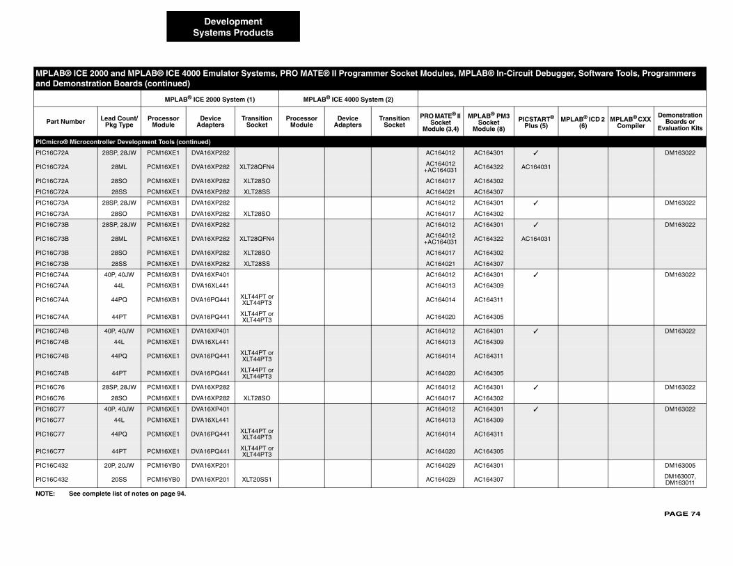
PAGE 74
PICmicr
PIC16C7 ✓ DM163022
PIC16C7 AC164031
PIC16C7
PIC16C7
PIC16C7 ✓ DM163022
PIC16C7
PIC16C7 ✓ DM163022
PIC16C7 AC164031
PIC16C7
PIC16C7
PIC16C7 ✓ DM163022
PIC16C7
PIC16C7
PIC16C7
PIC16C7 ✓ DM163022
PIC16C7
PIC16C7
PIC16C7
PIC16C7 ✓ DM163022
PIC16C7
PIC16C7 ✓ DM163022
PIC16C7
PIC16C7
PIC16C7
PIC16C4 DM163005
PIC16C4 DM163007, DM163011
MPLA ircuit Debugger, Software Tools, Programmers and D
Part PICSTART® Plus (5)
MPLAB® ICD 2 (6)
MPLAB® CXX Compiler
Demonstration Boards or
Evaluation Kits
NOTE:
DevelopmentSystems Products
o® Microcontroller Development Tools (continued)
2A 28SP, 28JW PCM16XE1 DVA16XP282 AC164012 AC164301
2A 28ML PCM16XE1 DVA16XP282 XLT28QFN4 AC164012+AC164031 AC164322
2A 28SO PCM16XE1 DVA16XP282 XLT28SO AC164017 AC164302
2A 28SS PCM16XE1 DVA16XP282 XLT28SS AC164021 AC164307
3A 28SP, 28JW PCM16XB1 DVA16XP282 AC164012 AC164301
3A 28SO PCM16XB1 DVA16XP282 XLT28SO AC164017 AC164302
3B 28SP, 28JW PCM16XE1 DVA16XP282 AC164012 AC164301
3B 28ML PCM16XE1 DVA16XP282 XLT28QFN4 AC164012+AC164031 AC164322
3B 28SO PCM16XE1 DVA16XP282 XLT28SO AC164017 AC164302
3B 28SS PCM16XE1 DVA16XP282 XLT28SS AC164021 AC164307
4A 40P, 40JW PCM16XB1 DVA16XP401 AC164012 AC164301
4A 44L PCM16XB1 DVA16XL441 AC164013 AC164309
4A 44PQ PCM16XB1 DVA16PQ441 XLT44PT or XLT44PT3 AC164014 AC164311
4A 44PT PCM16XB1 DVA16PQ441 XLT44PT or XLT44PT3 AC164020 AC164305
4B 40P, 40JW PCM16XE1 DVA16XP401 AC164012 AC164301
4B 44L PCM16XE1 DVA16XL441 AC164013 AC164309
4B 44PQ PCM16XE1 DVA16PQ441 XLT44PT or XLT44PT3 AC164014 AC164311
4B 44PT PCM16XE1 DVA16PQ441 XLT44PT or XLT44PT3 AC164020 AC164305
6 28SP, 28JW PCM16XE1 DVA16XP282 AC164012 AC164301
6 28SO PCM16XE1 DVA16XP282 XLT28SO AC164017 AC164302
7 40P, 40JW PCM16XE1 DVA16XP401 AC164012 AC164301
7 44L PCM16XE1 DVA16XL441 AC164013 AC164309
7 44PQ PCM16XE1 DVA16PQ441 XLT44PT or XLT44PT3 AC164014 AC164311
7 44PT PCM16XE1 DVA16PQ441 XLT44PT or XLT44PT3 AC164020 AC164305
32 20P, 20JW PCM16YB0 DVA16XP201 AC164029 AC164301
32 20SS PCM16YB0 DVA16XP201 XLT20SS1 AC164029 AC164307
B® ICE 2000 and MPLAB® ICE 4000 Emulator Systems, PRO MATE® II Programmer Socket Modules, MPLAB® In-Cemonstration Boards (continued)
MPLAB® ICE 2000 System (1) MPLAB® ICE 4000 System (2)
Number Lead Count/Pkg Type
Processor Module
Device Adapters
Transition Socket
Processor Module
Device Adapters
Transition Socket
PRO MATE® II Socket
Module (3,4)
MPLAB® PM3Socket
Module (8)
See complete list of notes on page 94.
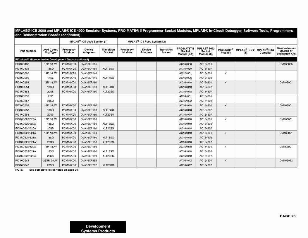
PAGE 75
PICmicr
PIC16C DM163005
PIC16C
PIC16C ✓
PIC16C
PIC16C ✓ DM163001
PIC16C
PIC16C
PIC16C
PIC16C
PIC16C ✓ DM163001
PIC16C
PIC16C
PIC16C ✓ DM163001
PIC16C
PIC16C
PIC16C ✓ DM163001
PIC16C
PIC16C
PIC16C ✓ DM163001
PIC16C
PIC16C
PIC16C ✓ DM163022
PIC16C
MPLA ircuit Debugger, Software Tools, Programmers and D
Part PICSTART® Plus (5)
MPLAB® ICD 2 (6)
MPLAB® CXX Compiler
Demonstration Boards or
Evaluation Kits
NOTE:
DevelopmentSystems Products
o® Microcontroller Development Tools (continued)
433 18P, 18JW PCM16YC0 DVA16XP185 AC164030 AC164301
433 18SO PCM16YC0 DVA16XP185 XLT18SO AC164030 AC164307
505 14P, 14JW PCM16XA0 DVA16XP140 AC124001 AC164301
505 14SL PCM16XA0 DVA16XP140 XLT14SO AC164026 AC164302
554 18P, 18JW PCM16XC0 DVA16XP180 AC164010 AC164301
554 18SO PCM16XC0 DVA16XP180 XLT18SO AC164010 AC164302
554 20SS PCM16XC0 DVA16XP180 XLT20SS AC164018 AC164307
557 28P AC164001 AC164301
557 28SO AC164002 AC164302
558 18P, 18JW PCM16XC0 DVA16XP180 AC164010 AC164301
558 18SO PCM16XC0 DVA16XP180 XLT18SO AC164010 AC164302
558 20SS PCM16XC0 DVA16XP180 XLT20SS AC164018 AC164307
620/620A 18P, 18JW PCM16XC0 DVA16XP180 AC164010 AC164301
620/620A 18SO PCM16XC0 DVA16XP180 XLT18SO AC164010 AC164302
620/620A 20SS PCM16XC0 DVA16XP180 XLT20SS AC164018 AC164307
621/621A 18P, 18JW PCM16XC0 DVA16XP180 AC164010 AC164301
621/621A 18SO PCM16XC0 DVA16XP180 XLT18SO AC164010 AC164302
621/621A 20SS PCM16XC0 DVA16XP180 XLT20SS AC164018 AC164307
622/622A 18P, 18JW PCM16XC0 DVA16XP180 AC164010 AC164301
622/622A 18SO PCM16XC0 DVA16XP180 XLT18SO AC164010 AC164302
622/622A 20SS PCM16XC0 DVA16XP180 XLT20SS AC164018 AC164307
642 28SP, 28JW PCM16XD0 DVA16XP282 AC164012 AC164301
642 28SO PCM16XD0 DVA16XP282 XLT28SO AC164017 AC164302
B® ICE 2000 and MPLAB® ICE 4000 Emulator Systems, PRO MATE® II Programmer Socket Modules, MPLAB® In-Cemonstration Boards (continued)
MPLAB® ICE 2000 System (1) MPLAB® ICE 4000 System (2)
Number Lead Count/Pkg Type
Processor Module
Device Adapters
Transition Socket
Processor Module
Device Adapters
Transition Socket
PRO MATE® II Socket
Module (3,4)
MPLAB® PM3Socket
Module (8)
See complete list of notes on page 94.
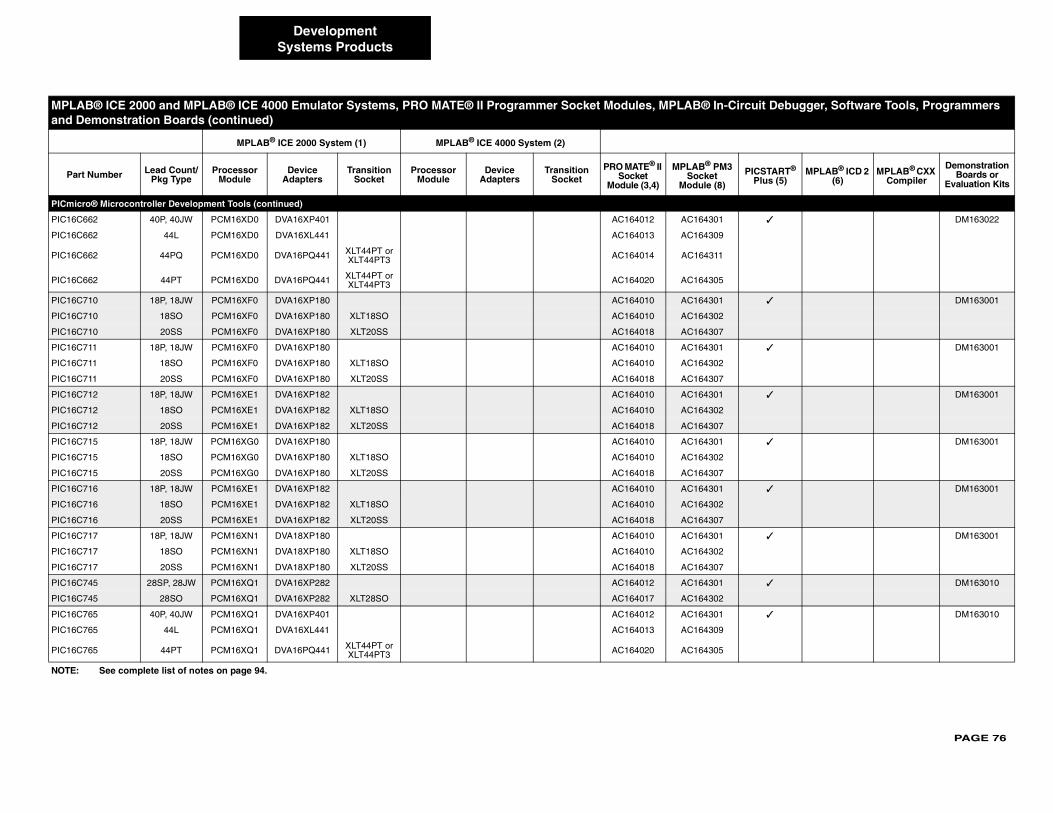
PAGE 76
PICmicr
PIC16C6 ✓ DM163022
PIC16C6
PIC16C6
PIC16C6
PIC16C7 ✓ DM163001
PIC16C7
PIC16C7
PIC16C7 ✓ DM163001
PIC16C7
PIC16C7
PIC16C7 ✓ DM163001
PIC16C7
PIC16C7
PIC16C7 ✓ DM163001
PIC16C7
PIC16C7
PIC16C7 ✓ DM163001
PIC16C7
PIC16C7
PIC16C7 ✓ DM163001
PIC16C7
PIC16C7
PIC16C7 ✓ DM163010
PIC16C7
PIC16C7 ✓ DM163010
PIC16C7
PIC16C7
MPLA ircuit Debugger, Software Tools, Programmers and D
Part PICSTART® Plus (5)
MPLAB® ICD 2 (6)
MPLAB® CXX Compiler
Demonstration Boards or
Evaluation Kits
NOTE:
DevelopmentSystems Products
o® Microcontroller Development Tools (continued)
62 40P, 40JW PCM16XD0 DVA16XP401 AC164012 AC164301
62 44L PCM16XD0 DVA16XL441 AC164013 AC164309
62 44PQ PCM16XD0 DVA16PQ441 XLT44PT or XLT44PT3 AC164014 AC164311
62 44PT PCM16XD0 DVA16PQ441 XLT44PT or XLT44PT3 AC164020 AC164305
10 18P, 18JW PCM16XF0 DVA16XP180 AC164010 AC164301
10 18SO PCM16XF0 DVA16XP180 XLT18SO AC164010 AC164302
10 20SS PCM16XF0 DVA16XP180 XLT20SS AC164018 AC164307
11 18P, 18JW PCM16XF0 DVA16XP180 AC164010 AC164301
11 18SO PCM16XF0 DVA16XP180 XLT18SO AC164010 AC164302
11 20SS PCM16XF0 DVA16XP180 XLT20SS AC164018 AC164307
12 18P, 18JW PCM16XE1 DVA16XP182 AC164010 AC164301
12 18SO PCM16XE1 DVA16XP182 XLT18SO AC164010 AC164302
12 20SS PCM16XE1 DVA16XP182 XLT20SS AC164018 AC164307
15 18P, 18JW PCM16XG0 DVA16XP180 AC164010 AC164301
15 18SO PCM16XG0 DVA16XP180 XLT18SO AC164010 AC164302
15 20SS PCM16XG0 DVA16XP180 XLT20SS AC164018 AC164307
16 18P, 18JW PCM16XE1 DVA16XP182 AC164010 AC164301
16 18SO PCM16XE1 DVA16XP182 XLT18SO AC164010 AC164302
16 20SS PCM16XE1 DVA16XP182 XLT20SS AC164018 AC164307
17 18P, 18JW PCM16XN1 DVA18XP180 AC164010 AC164301
17 18SO PCM16XN1 DVA18XP180 XLT18SO AC164010 AC164302
17 20SS PCM16XN1 DVA18XP180 XLT20SS AC164018 AC164307
45 28SP, 28JW PCM16XQ1 DVA16XP282 AC164012 AC164301
45 28SO PCM16XQ1 DVA16XP282 XLT28SO AC164017 AC164302
65 40P, 40JW PCM16XQ1 DVA16XP401 AC164012 AC164301
65 44L PCM16XQ1 DVA16XL441 AC164013 AC164309
65 44PT PCM16XQ1 DVA16PQ441 XLT44PT or XLT44PT3 AC164020 AC164305
B® ICE 2000 and MPLAB® ICE 4000 Emulator Systems, PRO MATE® II Programmer Socket Modules, MPLAB® In-Cemonstration Boards (continued)
MPLAB® ICE 2000 System (1) MPLAB® ICE 4000 System (2)
Number Lead Count/Pkg Type
Processor Module
Device Adapters
Transition Socket
Processor Module
Device Adapters
Transition Socket
PRO MATE® II Socket
Module (3,4)
MPLAB® PM3Socket
Module (8)
See complete list of notes on page 94.
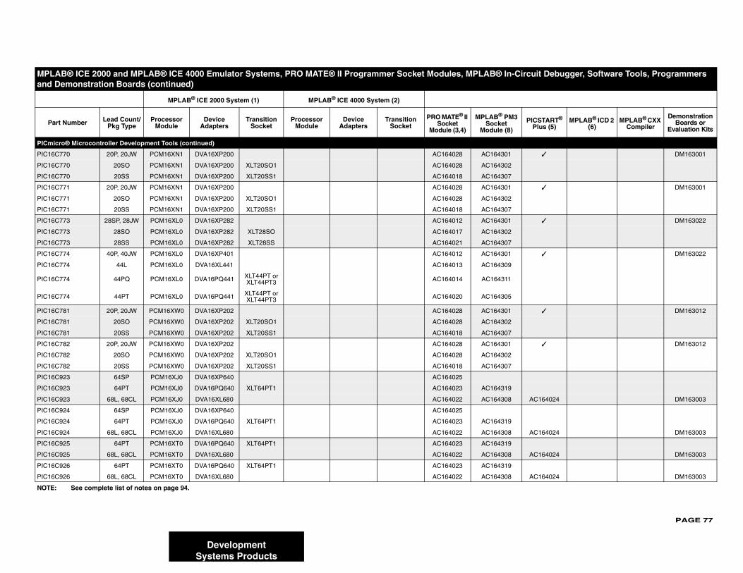
PAGE 77
PICmicr
PIC16C ✓ DM163001
PIC16C
PIC16C
PIC16C ✓ DM163001
PIC16C
PIC16C
PIC16C ✓ DM163022
PIC16C
PIC16C
PIC16C ✓ DM163022
PIC16C
PIC16C
PIC16C
PIC16C ✓ DM163012
PIC16C
PIC16C
PIC16C ✓ DM163012
PIC16C
PIC16C
PIC16C
PIC16C
PIC16C AC164024 DM163003
PIC16C
PIC16C
PIC16C AC164024 DM163003
PIC16C
PIC16C AC164024 DM163003
PIC16C
PIC16C AC164024 DM163003
MPLA ircuit Debugger, Software Tools, Programmers and D
Part PICSTART® Plus (5)
MPLAB® ICD 2 (6)
MPLAB® CXX Compiler
Demonstration Boards or
Evaluation Kits
NOTE:
DevelopmentSystems Products
o® Microcontroller Development Tools (continued)
770 20P, 20JW PCM16XN1 DVA16XP200 AC164028 AC164301
770 20SO PCM16XN1 DVA16XP200 XLT20SO1 AC164028 AC164302
770 20SS PCM16XN1 DVA16XP200 XLT20SS1 AC164018 AC164307
771 20P, 20JW PCM16XN1 DVA16XP200 AC164028 AC164301
771 20SO PCM16XN1 DVA16XP200 XLT20SO1 AC164028 AC164302
771 20SS PCM16XN1 DVA16XP200 XLT20SS1 AC164018 AC164307
773 28SP, 28JW PCM16XL0 DVA16XP282 AC164012 AC164301
773 28SO PCM16XL0 DVA16XP282 XLT28SO AC164017 AC164302
773 28SS PCM16XL0 DVA16XP282 XLT28SS AC164021 AC164307
774 40P, 40JW PCM16XL0 DVA16XP401 AC164012 AC164301
774 44L PCM16XL0 DVA16XL441 AC164013 AC164309
774 44PQ PCM16XL0 DVA16PQ441 XLT44PT or XLT44PT3 AC164014 AC164311
774 44PT PCM16XL0 DVA16PQ441 XLT44PT or XLT44PT3 AC164020 AC164305
781 20P, 20JW PCM16XW0 DVA16XP202 AC164028 AC164301
781 20SO PCM16XW0 DVA16XP202 XLT20SO1 AC164028 AC164302
781 20SS PCM16XW0 DVA16XP202 XLT20SS1 AC164018 AC164307
782 20P, 20JW PCM16XW0 DVA16XP202 AC164028 AC164301
782 20SO PCM16XW0 DVA16XP202 XLT20SO1 AC164028 AC164302
782 20SS PCM16XW0 DVA16XP202 XLT20SS1 AC164018 AC164307
923 64SP PCM16XJ0 DVA16XP640 AC164025
923 64PT PCM16XJ0 DVA16PQ640 XLT64PT1 AC164023 AC164319
923 68L, 68CL PCM16XJ0 DVA16XL680 AC164022 AC164308
924 64SP PCM16XJ0 DVA16XP640 AC164025
924 64PT PCM16XJ0 DVA16PQ640 XLT64PT1 AC164023 AC164319
924 68L, 68CL PCM16XJ0 DVA16XL680 AC164022 AC164308
925 64PT PCM16XT0 DVA16PQ640 XLT64PT1 AC164023 AC164319
925 68L, 68CL PCM16XT0 DVA16XL680 AC164022 AC164308
926 64PT PCM16XT0 DVA16PQ640 XLT64PT1 AC164023 AC164319
926 68L, 68CL PCM16XT0 DVA16XL680 AC164022 AC164308
B® ICE 2000 and MPLAB® ICE 4000 Emulator Systems, PRO MATE® II Programmer Socket Modules, MPLAB® In-Cemonstration Boards (continued)
MPLAB® ICE 2000 System (1) MPLAB® ICE 4000 System (2)
Number Lead Count/Pkg Type
Processor Module
Device Adapters
Transition Socket
Processor Module
Device Adapters
Transition Socket
PRO MATE® II Socket
Module (3,4)
MPLAB® PM3Socket
Module (8)
See complete list of notes on page 94.
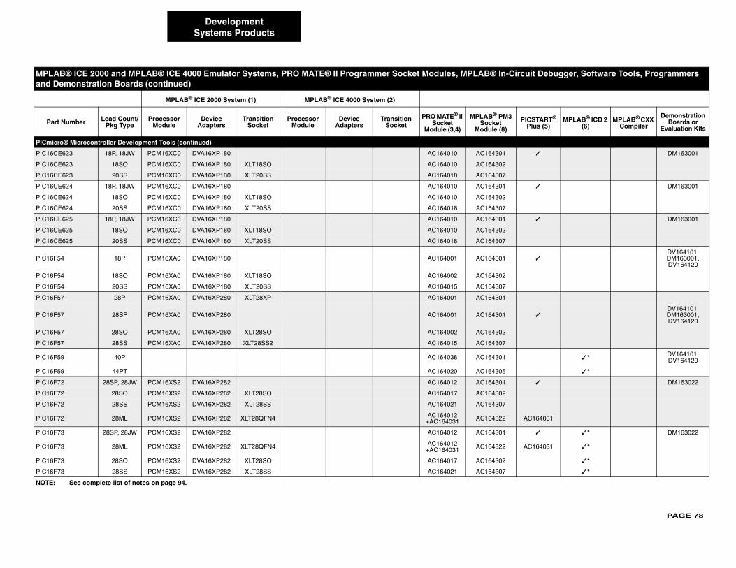
PAGE 78
PICmicr
PIC16CE ✓ DM163001
PIC16CE
PIC16CE
PIC16CE ✓ DM163001
PIC16CE
PIC16CE
PIC16CE ✓ DM163001
PIC16CE
PIC16CE
PIC16F5 ✓DV164101, DM163001, DV164120
PIC16F5
PIC16F5
PIC16F5
PIC16F5 ✓DV164101, DM163001, DV164120
PIC16F5
PIC16F5
PIC16F5 ✓ * DV164101,DV164120
PIC16F5 ✓ *
PIC16F7 ✓ DM163022
PIC16F7
PIC16F7
PIC16F7 AC164031
PIC16F7 ✓ ✓ * DM163022
PIC16F7 AC164031 ✓ *
PIC16F7 ✓ *
PIC16F7 ✓ *
MPLA ircuit Debugger, Software Tools, Programmers and D
Part PICSTART® Plus (5)
MPLAB® ICD 2 (6)
MPLAB® CXX Compiler
Demonstration Boards or
Evaluation Kits
NOTE:
DevelopmentSystems Products
o® Microcontroller Development Tools (continued)
623 18P, 18JW PCM16XC0 DVA16XP180 AC164010 AC164301
623 18SO PCM16XC0 DVA16XP180 XLT18SO AC164010 AC164302
623 20SS PCM16XC0 DVA16XP180 XLT20SS AC164018 AC164307
624 18P, 18JW PCM16XC0 DVA16XP180 AC164010 AC164301
624 18SO PCM16XC0 DVA16XP180 XLT18SO AC164010 AC164302
624 20SS PCM16XC0 DVA16XP180 XLT20SS AC164018 AC164307
625 18P, 18JW PCM16XC0 DVA16XP180 AC164010 AC164301
625 18SO PCM16XC0 DVA16XP180 XLT18SO AC164010 AC164302
625 20SS PCM16XC0 DVA16XP180 XLT20SS AC164018 AC164307
4 18P PCM16XA0 DVA16XP180 AC164001 AC164301
4 18SO PCM16XA0 DVA16XP180 XLT18SO AC164002 AC164302
4 20SS PCM16XA0 DVA16XP180 XLT20SS AC164015 AC164307
7 28P PCM16XA0 DVA16XP280 XLT28XP AC164001 AC164301
7 28SP PCM16XA0 DVA16XP280 AC164001 AC164301
7 28SO PCM16XA0 DVA16XP280 XLT28SO AC164002 AC164302
7 28SS PCM16XA0 DVA16XP280 XLT28SS2 AC164015 AC164307
9 40P AC164038 AC164301
9 44PT AC164020 AC164305
2 28SP, 28JW PCM16XS2 DVA16XP282 AC164012 AC164301
2 28SO PCM16XS2 DVA16XP282 XLT28SO AC164017 AC164302
2 28SS PCM16XS2 DVA16XP282 XLT28SS AC164021 AC164307
2 28ML PCM16XS2 DVA16XP282 XLT28QFN4 AC164012+AC164031 AC164322
3 28SP, 28JW PCM16XS2 DVA16XP282 AC164012 AC164301
3 28ML PCM16XS2 DVA16XP282 XLT28QFN4 AC164012+AC164031 AC164322
3 28SO PCM16XS2 DVA16XP282 XLT28SO AC164017 AC164302
3 28SS PCM16XS2 DVA16XP282 XLT28SS AC164021 AC164307
B® ICE 2000 and MPLAB® ICE 4000 Emulator Systems, PRO MATE® II Programmer Socket Modules, MPLAB® In-Cemonstration Boards (continued)
MPLAB® ICE 2000 System (1) MPLAB® ICE 4000 System (2)
Number Lead Count/Pkg Type
Processor Module
Device Adapters
Transition Socket
Processor Module
Device Adapters
Transition Socket
PRO MATE® II Socket
Module (3,4)
MPLAB® PM3Socket
Module (8)
See complete list of notes on page 94.
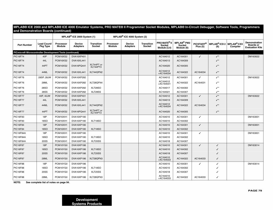
PAGE 79
PICmicr
PIC16F7 ✓ ✓ * DM163022
PIC16F7 ✓ *
PIC16F7 ✓ *
PIC16F7 AC164034 ✓ *
PIC16F7 ✓ ✓ * DM163022
PIC16F7 AC164031 ✓ *
PIC16F7 ✓ *
PIC16F7 ✓ *
PIC16F7 ✓ ✓ * DM163022
PIC16F7 ✓ *
PIC16F7 AC164034 ✓ *
PIC16F7 ✓ *
PIC16F8 ✓ DM163001
PIC16F8
PIC16F8 ✓ DM163001
PIC16F8
PIC16F8 ✓ DM163001
PIC16F8
PIC16F8
PIC16F8 ✓ ✓ DM163014
PIC16F8 ✓
PIC16F8 ✓
PIC16F8 AC164033 ✓
PIC16F8 ✓ ✓ DM163014
PIC16F8 ✓
PIC16F8 ✓
PIC16F8 AC164033 ✓
MPLA ircuit Debugger, Software Tools, Programmers and D
Part PICSTART® Plus (5)
MPLAB® ICD 2 (6)
MPLAB® CXX Compiler
Demonstration Boards or
Evaluation Kits
NOTE:
DevelopmentSystems Products
o® Microcontroller Development Tools (continued)
4 40P PCM16XS2 DVA16XP401 AC164012 AC164301
4 44L PCM16XS2 DVA16XL441 AC164013 AC164309
4 44PT PCM16XS2 DVA16PQ441 XLT44PT or XLT44PT3 AC164020 AC164305
4 44ML PCM16XS2 DVA16XL441 XLT44QFN2 AC164012+AC164034 AC164322
6 28SP, 28JW PCM16XS2 DVA16XP282 AC164012 AC164301
6 28ML PCM16XS2 DVA16XP282 XLT28QFN4 AC164012+AC164031 AC164322
6 28SO PCM16XS2 DVA16XP282 XLT28SO AC164017 AC164302
6 28SS PCM16XS2 DVA16XP282 XLT28SS AC164021 AC164307
7 40P, 40JW PCM16XS2 DVA16XP401 AC164012 AC164301
7 44L PCM16XS2 DVA16XL441 AC164013 AC164309
7 44ML PCM16XS2 DVA16XL441 XLT44QFN2 AC164012+AC164034 AC164322
7 44PT PCM16XS2 DVA16PQ441 XLT44PT or XLT44PT3 AC164020 AC164305
3 18P PCM16XH1 DVA16XP180 AC164010 AC164301
3 18SO PCM16XH1 DVA16XP180 XLT18SO AC164010 AC164302
4 18P PCM16XH1 DVA16XP180 AC164010 AC164301
4 18SO PCM16XH1 DVA16XP180 XLT18SO AC164010 AC164302
4A 18P PCM16XH1 DVA16XP180 AC164010 AC164301
4A 18SO PCM16XH1 DVA16XP180 XLT18SO AC164010 AC164302
4A 20SS PCM16XH1 DVA16XP180 XLT20SS AC164018 AC164307
7 18P PCM16YG0 DVA16XP186 AC164010 AC164301
7 18SO PCM16YG0 DVA16XP186 XLT18SO AC164010 AC164302
7 20SS PCM16YG0 DVA16XP186 XLT20SS AC164018 AC164307
7 28ML PCM16YG0 DVA16XP186 XLT28QFN3 AC164010+AC164033 AC164322
8 18P PCM16YG0 DVA16XP186 AC164010 AC164301
8 18SO PCM16YG0 DVA16XP186 XLT18SO AC164010 AC164302
8 20SS PCM16YG0 DVA16XP186 XLT20SS AC164018 AC164307
8 28ML PCM16YG0 DVA16XP186 XLT28QFN3 AC164010+AC164033 AC164322
B® ICE 2000 and MPLAB® ICE 4000 Emulator Systems, PRO MATE® II Programmer Socket Modules, MPLAB® In-Cemonstration Boards (continued)
MPLAB® ICE 2000 System (1) MPLAB® ICE 4000 System (2)
Number Lead Count/Pkg Type
Processor Module
Device Adapters
Transition Socket
Processor Module
Device Adapters
Transition Socket
PRO MATE® II Socket
Module (3,4)
MPLAB® PM3Socket
Module (8)
See complete list of notes on page 94.
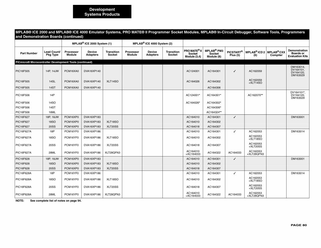
PAGE 80
PICmicr
PIC16F5 ✓ AC162059
DM163014, DV164101, DV164120, DM163029
PIC16F5 AC162059 +XLT14SO
PIC16F5
PIC16F5 AC162070**DV164101*, DV164120, DM163029
PIC16F5
PIC16F5
PIC16F5
PIC16F6 ✓ DM163001
PIC16F6
PIC16F6
PIC16F6 ✓ AC162053 DM163014
PIC16F6 AC162053 +XLT18SO
PIC16F6 AC162053 +XLT20SS
PIC16F6 AC164033 AC162053 +XLT28QFN3
PIC16F6 ✓ DM163001
PIC16F6
PIC16F6
PIC16F6 ✓ AC162053 DM163014
PIC16F6 AC162053 +XLT18SO
PIC16F6 AC162053 +XLT20SS
PIC16F6 AC164033 AC162053 +XLT28QFN3
MPLA ircuit Debugger, Software Tools, Programmers and D
Part PICSTART® Plus (5)
MPLAB® ICD 2 (6)
MPLAB® CXX Compiler
Demonstration Boards or
Evaluation Kits
NOTE:
DevelopmentSystems Products
o® Microcontroller Development Tools (continued)
05 14P, 14JW PCM16XA0 DVA16XP140 AC124001 AC164301
05 14SL PCM16XA0 DVA16XP140 XLT14SO AC164026 AC164302
05 14ST PCM16XA0 DVA16XP140 AC164306
06 14P AC124001* AC164301*
06 14SO AC164026* AC164302*
06 14ST AC164306*
06 16ML AC164324**
27 18P, 18JW PCM16XP0 DVA16XP183 AC164010 AC164301
27 18SO PCM16XP0 DVA16XP183 XLT18SO AC164010 AC164302
27 20SS PCM16XP0 DVA16XP183 XLT20SS AC164018 AC164307
27A 18P PCM16YF0 DVA16XP186 AC164010 AC164301
27A 18SO PCM16YF0 DVA16XP186 XLT18SO AC164010 AC164302
27A 20SS PCM16YF0 DVA16XP186 XLT20SS AC164018 AC164307
27A 28ML PCM16YF0 DVA16XP186 XLT28QFN3 AC164010+AC164033 AC164322
28 18P, 18JW PCM16XP0 DVA16XP183 AC164010 AC164301
28 18SO PCM16XP0 DVA16XP183 XLT18SO AC164010 AC164302
28 20SS PCM16XP0 DVA16XP183 XLT20SS AC164018 AC164307
28A 18P PCM16YF0 DVA16XP186 AC164010 AC164301
28A 18SO PCM16YF0 DVA16XP186 XLT18SO AC164010 AC164302
28A 20SS PCM16YF0 DVA16XP186 XLT20SS AC164018 AC164307
28A 28ML PCM16YF0 DVA16XP186 XLT28QFN3 AC164010+AC164033 AC164322
B® ICE 2000 and MPLAB® ICE 4000 Emulator Systems, PRO MATE® II Programmer Socket Modules, MPLAB® In-Cemonstration Boards (continued)
MPLAB® ICE 2000 System (1) MPLAB® ICE 4000 System (2)
Number Lead Count/Pkg Type
Processor Module
Device Adapters
Transition Socket
Processor Module
Device Adapters
Transition Socket
PRO MATE® II Socket
Module (3,4)
MPLAB® PM3Socket
Module (8)
See complete list of notes on page 94.
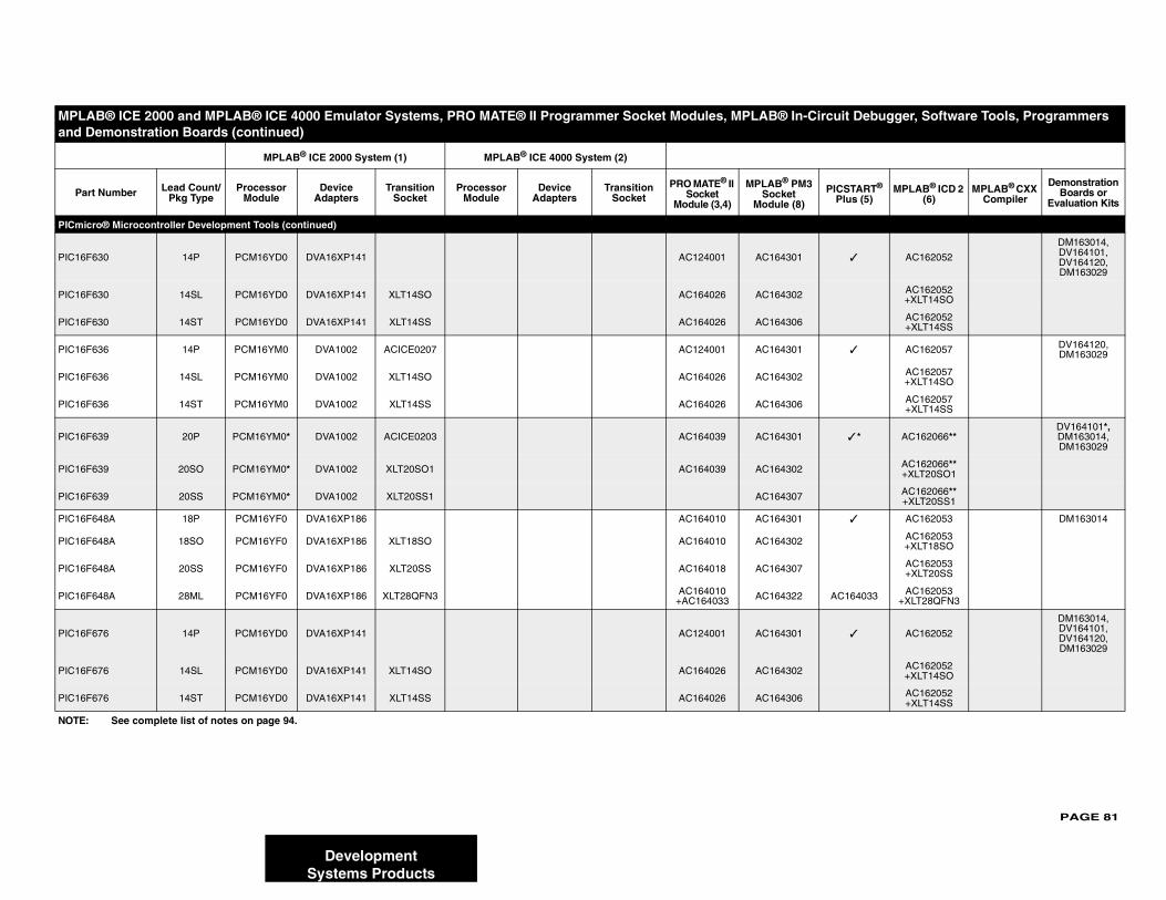
PAGE 81
PICmicr
PIC16F6 ✓ AC162052
DM163014, DV164101, DV164120,DM163029
PIC16F6 AC162052 +XLT14SO
PIC16F6 AC162052 +XLT14SS
PIC16F6 ✓ AC162057 DV164120, DM163029
PIC16F6 AC162057 +XLT14SO
PIC16F6 AC162057 +XLT14SS
PIC16F6 ✓ * AC162066**DV164101*, DM163014, DM163029
PIC16F6 AC162066** +XLT20SO1
PIC16F6 AC162066** +XLT20SS1
PIC16F6 ✓ AC162053 DM163014
PIC16F6 AC162053 +XLT18SO
PIC16F6 AC162053 +XLT20SS
PIC16F6 AC164033 AC162053 +XLT28QFN3
PIC16F6 ✓ AC162052
DM163014, DV164101, DV164120,DM163029
PIC16F6 AC162052 +XLT14SO
PIC16F6 AC162052 +XLT14SS
MPLA ircuit Debugger, Software Tools, Programmers and D
Part PICSTART® Plus (5)
MPLAB® ICD 2 (6)
MPLAB® CXX Compiler
Demonstration Boards or
Evaluation Kits
NOTE:
DevelopmentSystems Products
o® Microcontroller Development Tools (continued)
30 14P PCM16YD0 DVA16XP141 AC124001 AC164301
30 14SL PCM16YD0 DVA16XP141 XLT14SO AC164026 AC164302
30 14ST PCM16YD0 DVA16XP141 XLT14SS AC164026 AC164306
36 14P PCM16YM0 DVA1002 ACICE0207 AC124001 AC164301
36 14SL PCM16YM0 DVA1002 XLT14SO AC164026 AC164302
36 14ST PCM16YM0 DVA1002 XLT14SS AC164026 AC164306
39 20P PCM16YM0* DVA1002 ACICE0203 AC164039 AC164301
39 20SO PCM16YM0* DVA1002 XLT20SO1 AC164039 AC164302
39 20SS PCM16YM0* DVA1002 XLT20SS1 AC164307
48A 18P PCM16YF0 DVA16XP186 AC164010 AC164301
48A 18SO PCM16YF0 DVA16XP186 XLT18SO AC164010 AC164302
48A 20SS PCM16YF0 DVA16XP186 XLT20SS AC164018 AC164307
48A 28ML PCM16YF0 DVA16XP186 XLT28QFN3 AC164010+AC164033 AC164322
76 14P PCM16YD0 DVA16XP141 AC124001 AC164301
76 14SL PCM16YD0 DVA16XP141 XLT14SO AC164026 AC164302
76 14ST PCM16YD0 DVA16XP141 XLT14SS AC164026 AC164306
B® ICE 2000 and MPLAB® ICE 4000 Emulator Systems, PRO MATE® II Programmer Socket Modules, MPLAB® In-Cemonstration Boards (continued)
MPLAB® ICE 2000 System (1) MPLAB® ICE 4000 System (2)
Number Lead Count/Pkg Type
Processor Module
Device Adapters
Transition Socket
Processor Module
Device Adapters
Transition Socket
PRO MATE® II Socket
Module (3,4)
MPLAB® PM3Socket
Module (8)
See complete list of notes on page 94.
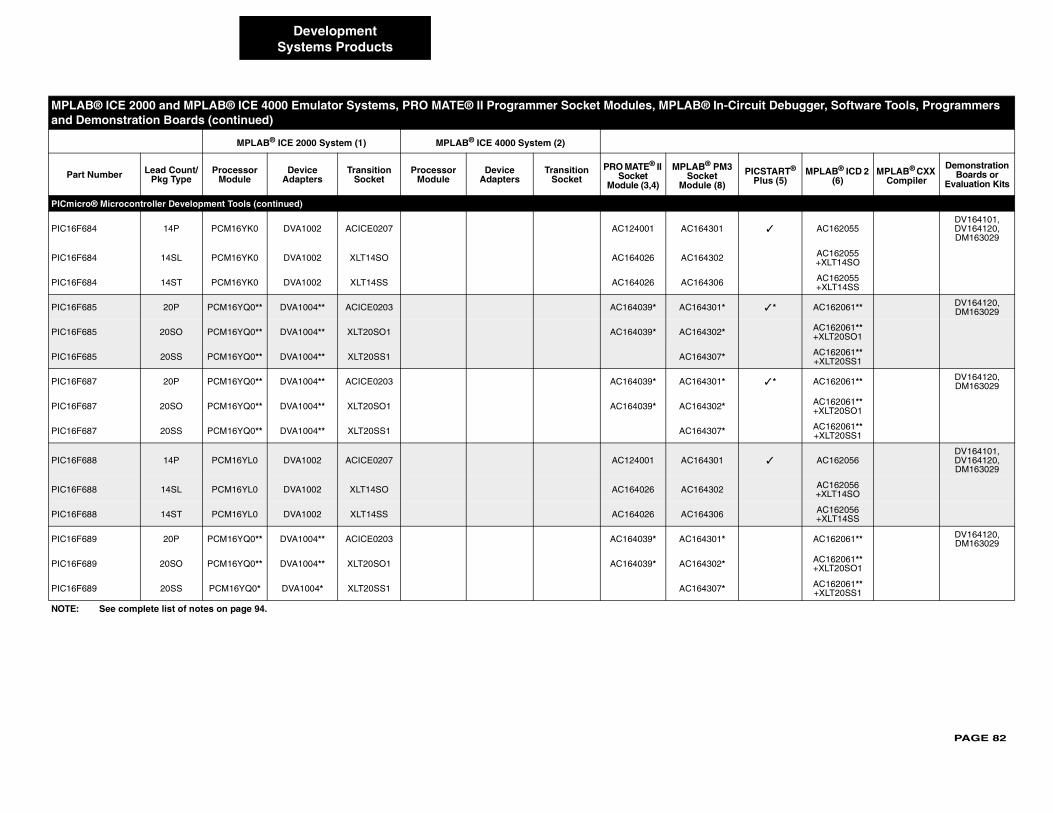
PAGE 82
PICmicr
PIC16F6 ✓ AC162055DV164101, DV164120, DM163029
PIC16F6 AC162055 +XLT14SO
PIC16F6 AC162055 +XLT14SS
PIC16F6 ✓ * AC162061** DV164120, DM163029
PIC16F6 AC162061** +XLT20SO1
PIC16F6 AC162061** +XLT20SS1
PIC16F6 ✓ * AC162061** DV164120, DM163029
PIC16F6 AC162061** +XLT20SO1
PIC16F6 AC162061** +XLT20SS1
PIC16F6 ✓ AC162056DV164101, DV164120, DM163029
PIC16F6 AC162056 +XLT14SO
PIC16F6 AC162056 +XLT14SS
PIC16F6 AC162061** DV164120, DM163029
PIC16F6 AC162061** +XLT20SO1
PIC16F6 AC162061** +XLT20SS1
MPLA ircuit Debugger, Software Tools, Programmers and D
Part PICSTART® Plus (5)
MPLAB® ICD 2 (6)
MPLAB® CXX Compiler
Demonstration Boards or
Evaluation Kits
NOTE:
DevelopmentSystems Products
o® Microcontroller Development Tools (continued)
84 14P PCM16YK0 DVA1002 ACICE0207 AC124001 AC164301
84 14SL PCM16YK0 DVA1002 XLT14SO AC164026 AC164302
84 14ST PCM16YK0 DVA1002 XLT14SS AC164026 AC164306
85 20P PCM16YQ0** DVA1004** ACICE0203 AC164039* AC164301*
85 20SO PCM16YQ0** DVA1004** XLT20SO1 AC164039* AC164302*
85 20SS PCM16YQ0** DVA1004** XLT20SS1 AC164307*
87 20P PCM16YQ0** DVA1004** ACICE0203 AC164039* AC164301*
87 20SO PCM16YQ0** DVA1004** XLT20SO1 AC164039* AC164302*
87 20SS PCM16YQ0** DVA1004** XLT20SS1 AC164307*
88 14P PCM16YL0 DVA1002 ACICE0207 AC124001 AC164301
88 14SL PCM16YL0 DVA1002 XLT14SO AC164026 AC164302
88 14ST PCM16YL0 DVA1002 XLT14SS AC164026 AC164306
89 20P PCM16YQ0** DVA1004** ACICE0203 AC164039* AC164301*
89 20SO PCM16YQ0** DVA1004** XLT20SO1 AC164039* AC164302*
89 20SS PCM16YQ0* DVA1004* XLT20SS1 AC164307*
B® ICE 2000 and MPLAB® ICE 4000 Emulator Systems, PRO MATE® II Programmer Socket Modules, MPLAB® In-Cemonstration Boards (continued)
MPLAB® ICE 2000 System (1) MPLAB® ICE 4000 System (2)
Number Lead Count/Pkg Type
Processor Module
Device Adapters
Transition Socket
Processor Module
Device Adapters
Transition Socket
PRO MATE® II Socket
Module (3,4)
MPLAB® PM3Socket
Module (8)
See complete list of notes on page 94.
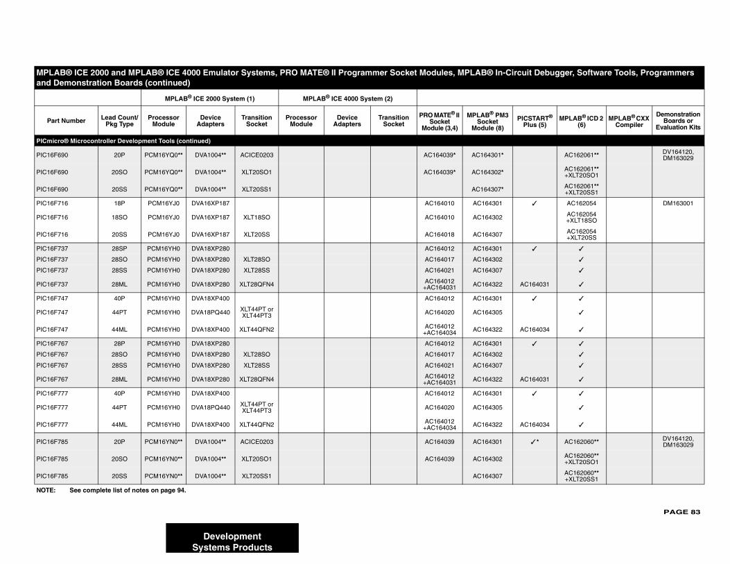
PAGE 83
PICmicr
PIC16F6 AC162061** DV164120, DM163029
PIC16F6 AC162061** +XLT20SO1
PIC16F6 AC162061** +XLT20SS1
PIC16F7 ✓ AC162054 DM163001
PIC16F7 AC162054 +XLT18SO
PIC16F7 AC162054 +XLT20SS
PIC16F7 ✓ ✓
PIC16F7 ✓
PIC16F7 ✓
PIC16F7 AC164031 ✓
PIC16F7 ✓ ✓
PIC16F7 ✓
PIC16F7 AC164034 ✓
PIC16F7 ✓ ✓
PIC16F7 ✓
PIC16F7 ✓
PIC16F7 AC164031 ✓
PIC16F7 ✓ ✓
PIC16F7 ✓
PIC16F7 AC164034 ✓
PIC16F7 ✓ * AC162060** DV164120, DM163029
PIC16F7 AC162060** +XLT20SO1
PIC16F7 AC162060** +XLT20SS1
MPLA ircuit Debugger, Software Tools, Programmers and D
Part PICSTART® Plus (5)
MPLAB® ICD 2 (6)
MPLAB® CXX Compiler
Demonstration Boards or
Evaluation Kits
NOTE:
DevelopmentSystems Products
o® Microcontroller Development Tools (continued)
90 20P PCM16YQ0** DVA1004** ACICE0203 AC164039* AC164301*
90 20SO PCM16YQ0** DVA1004** XLT20SO1 AC164039* AC164302*
90 20SS PCM16YQ0** DVA1004** XLT20SS1 AC164307*
16 18P PCM16YJ0 DVA16XP187 AC164010 AC164301
16 18SO PCM16YJ0 DVA16XP187 XLT18SO AC164010 AC164302
16 20SS PCM16YJ0 DVA16XP187 XLT20SS AC164018 AC164307
37 28SP PCM16YH0 DVA18XP280 AC164012 AC164301
37 28SO PCM16YH0 DVA18XP280 XLT28SO AC164017 AC164302
37 28SS PCM16YH0 DVA18XP280 XLT28SS AC164021 AC164307
37 28ML PCM16YH0 DVA18XP280 XLT28QFN4 AC164012+AC164031 AC164322
47 40P PCM16YH0 DVA18XP400 AC164012 AC164301
47 44PT PCM16YH0 DVA18PQ440 XLT44PT or XLT44PT3 AC164020 AC164305
47 44ML PCM16YH0 DVA18XP400 XLT44QFN2 AC164012+AC164034 AC164322
67 28P PCM16YH0 DVA18XP280 AC164012 AC164301
67 28SO PCM16YH0 DVA18XP280 XLT28SO AC164017 AC164302
67 28SS PCM16YH0 DVA18XP280 XLT28SS AC164021 AC164307
67 28ML PCM16YH0 DVA18XP280 XLT28QFN4 AC164012+AC164031 AC164322
77 40P PCM16YH0 DVA18XP400 AC164012 AC164301
77 44PT PCM16YH0 DVA18PQ440 XLT44PT or XLT44PT3 AC164020 AC164305
77 44ML PCM16YH0 DVA18XP400 XLT44QFN2 AC164012+AC164034 AC164322
85 20P PCM16YN0** DVA1004** ACICE0203 AC164039 AC164301
85 20SO PCM16YN0** DVA1004** XLT20SO1 AC164039 AC164302
85 20SS PCM16YN0** DVA1004** XLT20SS1 AC164307
B® ICE 2000 and MPLAB® ICE 4000 Emulator Systems, PRO MATE® II Programmer Socket Modules, MPLAB® In-Cemonstration Boards (continued)
MPLAB® ICE 2000 System (1) MPLAB® ICE 4000 System (2)
Number Lead Count/Pkg Type
Processor Module
Device Adapters
Transition Socket
Processor Module
Device Adapters
Transition Socket
PRO MATE® II Socket
Module (3,4)
MPLAB® PM3Socket
Module (8)
See complete list of notes on page 94.
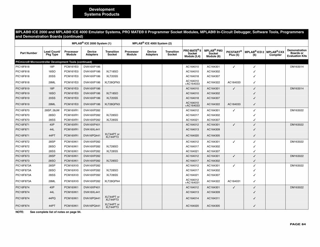
PAGE 84
PICmicr
PIC16F8 ✓ ✓ DM163014
PIC16F8 ✓
PIC16F8 ✓
PIC16F8 AC164033 ✓
PIC16F8 ✓ ✓ DM163014
PIC16F8 ✓
PIC16F8 ✓
PIC16F8 AC164033 ✓
PIC16F8 ✓ ✓ DM163022
PIC16F8 ✓
PIC16F8 ✓
PIC16F8 ✓ ✓ DM163022
PIC16F8 ✓
PIC16F8 ✓
PIC16F8 ✓ ✓ DM163022
PIC16F8 ✓
PIC16F8 ✓
PIC16F8 ✓ ✓ DM163022
PIC16F8 ✓
PIC16F8 ✓ ✓ DM163022
PIC16F8 ✓
PIC16F8 ✓
PIC16F8 AC164031 ✓
PIC16F8 ✓ ✓ DM163022
PIC16F8 ✓
PIC16F8 ✓
PIC16F8 ✓
MPLA ircuit Debugger, Software Tools, Programmers and D
Part PICSTART® Plus (5)
MPLAB® ICD 2 (6)
MPLAB® CXX Compiler
Demonstration Boards or
Evaluation Kits
NOTE:
DevelopmentSystems Products
o® Microcontroller Development Tools (continued)
18 18P PCM16YE0 DVA16XP186 AC164010 AC164301
18 18SO PCM16YE0 DVA16XP186 XLT18SO AC164010 AC164302
18 20SS PCM16YE0 DVA16XP186 XLT20SS AC164018 AC164307
18 28ML PCM16YE0 DVA16XP186 XLT28QFN3 AC164010+AC164033 AC164322
19 18P PCM16YE0 DVA16XP186 AC164010 AC164301
19 18SO PCM16YE0 DVA16XP186 XLT18SO AC164010 AC164302
19 20SS PCM16YE0 DVA16XP186 XLT20SS AC164018 AC164307
19 28ML PCM16YE0 DVA16XP186 XLT28QFN3 AC164010+AC164033 AC164322
70 28SP, 28JW PCM16XR1 DVA16XP282 AC164012 AC164301
70 28SO PCM16XR1 DVA16XP282 XLT28SO AC164017 AC164302
70 28SS PCM16XR1 DVA16XP282 XLT28SS AC164021 AC164307
71 40P PCM16XR1 DVA16XP401 AC164012 AC164301
71 44L PCM16XR1 DVA16XL441 AC164013 AC164309
71 44PT PCM16XR1 DVA16PQ441 XLT44PT or XLT44PT3 AC164020 AC164305
72 28SP PCM16XK1 DVA16XP282 AC164012 AC164301
72 28SO PCM16XK1 DVA16XP282 XLT28SO AC164017 AC164302
72 28SS PCM16XK1 DVA16XP282 XLT28SS AC164021 AC164307
73 28SP PCM16XK1 DVA16XP282 AC164012 AC164301
73 28SO PCM16XK1 DVA16XP282 XLT28SO AC164017 AC164302
73A 28SP PCM16XV0 DVA16XP282 AC164012 AC164301
73A 28SO PCM16XV0 DVA16XP282 XLT28SO AC164017 AC164302
73A 28SS PCM16XV0 DVA16XP282 XLT28SS AC164021 AC164307
73A 28ML PCM16XV0 DVA16XP282 XLT28QFN4 AC164012+AC164031 AC164322
74 40P PCM16XK1 DVA16XP401 AC164012 AC164301
74 44L PCM16XK1 DVA16XL441 AC164013 AC164309
74 44PQ PCM16XK1 DVA16PQ441 XLT44PT or XLT44PT3 AC164014 AC164311
74 44PT PCM16XK1 DVA16PQ441 XLT44PT or XLT44PT3 AC164020 AC164305
B® ICE 2000 and MPLAB® ICE 4000 Emulator Systems, PRO MATE® II Programmer Socket Modules, MPLAB® In-Cemonstration Boards (continued)
MPLAB® ICE 2000 System (1) MPLAB® ICE 4000 System (2)
Number Lead Count/Pkg Type
Processor Module
Device Adapters
Transition Socket
Processor Module
Device Adapters
Transition Socket
PRO MATE® II Socket
Module (3,4)
MPLAB® PM3Socket
Module (8)
See complete list of notes on page 94.
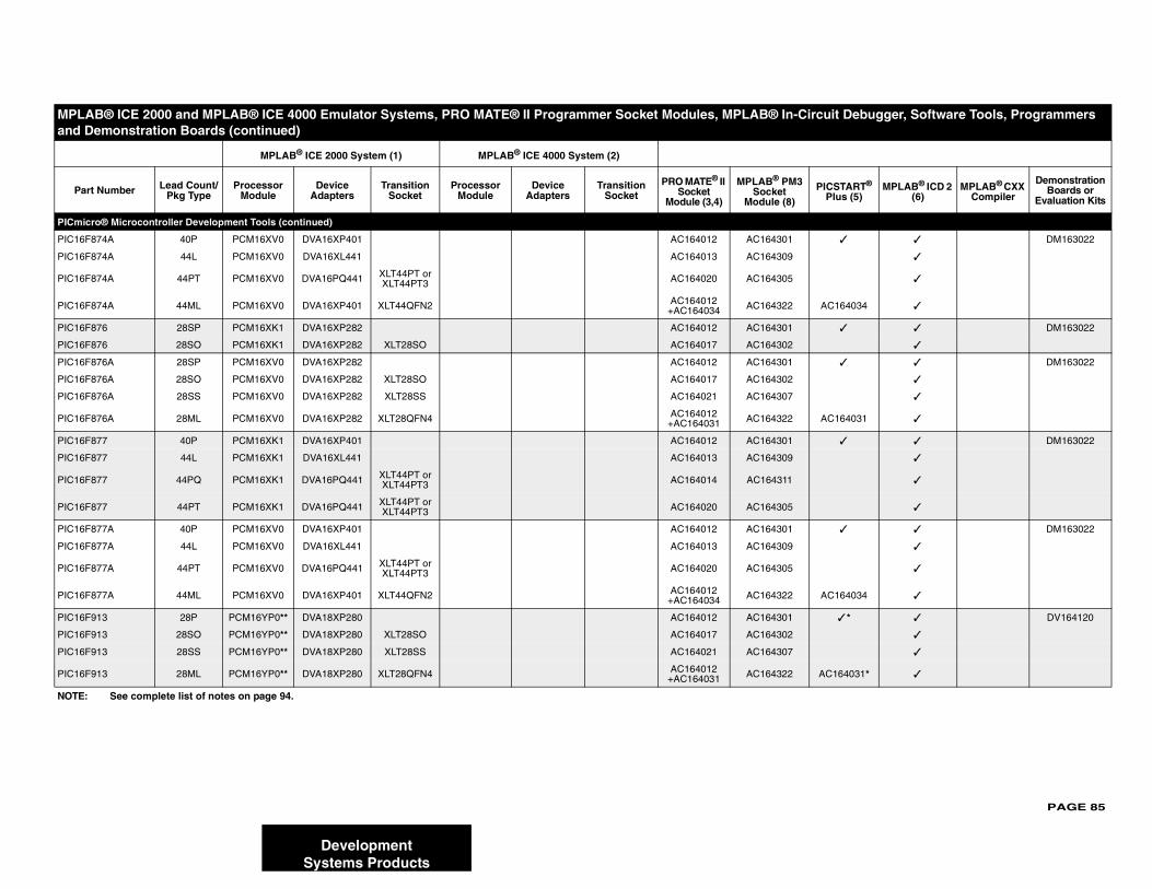
PAGE 85
PICmicr
PIC16F8 ✓ ✓ DM163022
PIC16F8 ✓
PIC16F8 ✓
PIC16F8 AC164034 ✓
PIC16F8 ✓ ✓ DM163022
PIC16F8 ✓
PIC16F8 ✓ ✓ DM163022
PIC16F8 ✓
PIC16F8 ✓
PIC16F8 AC164031 ✓
PIC16F8 ✓ ✓ DM163022
PIC16F8 ✓
PIC16F8 ✓
PIC16F8 ✓
PIC16F8 ✓ ✓ DM163022
PIC16F8 ✓
PIC16F8 ✓
PIC16F8 AC164034 ✓
PIC16F9 ✓ * ✓ DV164120
PIC16F9 ✓
PIC16F9 ✓
PIC16F9 AC164031* ✓
MPLA ircuit Debugger, Software Tools, Programmers and D
Part PICSTART® Plus (5)
MPLAB® ICD 2 (6)
MPLAB® CXX Compiler
Demonstration Boards or
Evaluation Kits
NOTE:
DevelopmentSystems Products
o® Microcontroller Development Tools (continued)
74A 40P PCM16XV0 DVA16XP401 AC164012 AC164301
74A 44L PCM16XV0 DVA16XL441 AC164013 AC164309
74A 44PT PCM16XV0 DVA16PQ441 XLT44PT or XLT44PT3 AC164020 AC164305
74A 44ML PCM16XV0 DVA16XP401 XLT44QFN2 AC164012+AC164034 AC164322
76 28SP PCM16XK1 DVA16XP282 AC164012 AC164301
76 28SO PCM16XK1 DVA16XP282 XLT28SO AC164017 AC164302
76A 28SP PCM16XV0 DVA16XP282 AC164012 AC164301
76A 28SO PCM16XV0 DVA16XP282 XLT28SO AC164017 AC164302
76A 28SS PCM16XV0 DVA16XP282 XLT28SS AC164021 AC164307
76A 28ML PCM16XV0 DVA16XP282 XLT28QFN4 AC164012+AC164031 AC164322
77 40P PCM16XK1 DVA16XP401 AC164012 AC164301
77 44L PCM16XK1 DVA16XL441 AC164013 AC164309
77 44PQ PCM16XK1 DVA16PQ441 XLT44PT or XLT44PT3 AC164014 AC164311
77 44PT PCM16XK1 DVA16PQ441 XLT44PT or XLT44PT3 AC164020 AC164305
77A 40P PCM16XV0 DVA16XP401 AC164012 AC164301
77A 44L PCM16XV0 DVA16XL441 AC164013 AC164309
77A 44PT PCM16XV0 DVA16PQ441 XLT44PT or XLT44PT3 AC164020 AC164305
77A 44ML PCM16XV0 DVA16XP401 XLT44QFN2 AC164012+AC164034 AC164322
13 28P PCM16YP0** DVA18XP280 AC164012 AC164301
13 28SO PCM16YP0** DVA18XP280 XLT28SO AC164017 AC164302
13 28SS PCM16YP0** DVA18XP280 XLT28SS AC164021 AC164307
13 28ML PCM16YP0** DVA18XP280 XLT28QFN4 AC164012 +AC164031 AC164322
B® ICE 2000 and MPLAB® ICE 4000 Emulator Systems, PRO MATE® II Programmer Socket Modules, MPLAB® In-Cemonstration Boards (continued)
MPLAB® ICE 2000 System (1) MPLAB® ICE 4000 System (2)
Number Lead Count/Pkg Type
Processor Module
Device Adapters
Transition Socket
Processor Module
Device Adapters
Transition Socket
PRO MATE® II Socket
Module (3,4)
MPLAB® PM3Socket
Module (8)
See complete list of notes on page 94.
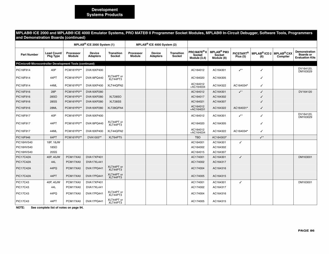
PAGE 86
PICmicr
PIC16F9 ✓ * ✓DV164120, DM163029
PIC16F9 ✓
PIC16F9 AC164034* ✓
PIC16F9 ✓ * ✓ DV164120
PIC16F9 ✓
PIC16F9 ✓
PIC16F9 AC164031* ✓
PIC16F9 ✓ * ✓DV164120, DM163029
PIC16F9 ✓
PIC16F9 AC164034* ✓
PIC16F9 ✓ *
PIC16HV ✓
PIC16HV
PIC16HV
PIC17C4 ✓ DM163001
PIC17C4
PIC17C4
PIC17C4
PIC17C4 ✓ DM163001
PIC17C4
PIC17C4
PIC17C4
MPLA ircuit Debugger, Software Tools, Programmers and D
Part PICSTART® Plus (5)
MPLAB® ICD 2 (6)
MPLAB® CXX Compiler
Demonstration Boards or
Evaluation Kits
NOTE:
DevelopmentSystems Products
o® Microcontroller Development Tools (continued)
14 40P PCM16YP0** DVA18XP400 AC164012 AC164301
14 44PT PCM16YP0** DVA18PQ440 XLT44PT or XLT44PT3 AC164020 AC164305
14 44ML PCM16YP0** DVA18XP400 XLT44QFN2 AC164012 +AC164034 AC164322
16 28P PCM16YP0** DVA18XP280 AC164012 AC164301
16 28SO PCM16YP0** DVA18XP280 XLT28SO AC164017 AC164302
16 28SS PCM16YP0** DVA18XP280 XLT28SS AC164021 AC164307
16 28ML PCM16YP0** DVA18XP280 XLT28QFN4 AC164012 +AC164031 AC164322
17 40P PCM16YP0** DVA18XP400 AC164012 AC164301
17 44PT PCM16YP0** DVA18PQ440 XLT44PT or XLT44PT3 AC164020 AC164305
17 44ML PCM16YP0** DVA18XP400 XLT44QFN2 AC164012 +AC164034 AC164322
46 64PT PCM16YP0** DVA1005** XLT64PT5 TBD AC164303*
540 18P, 18JW AC164001 AC164301
540 18SO AC164002 AC164302
540 20SS AC164015 AC164307
2A 40P, 40JW PCM17XA0 DVA17XP401 AC174001 AC164301
2A 44L PCM17XA0 DVA17XL441 AC174002 AC164317
2A 44PQ PCM17XA0 DVA17PQ441 XLT44PT or XLT44PT3 AC174004 AC164316
2A 44PT PCM17XA0 DVA17PQ441 XLT44PT or XLT44PT3 AC174005 AC164315
3 40P, 40JW PCM17XA0 DVA17XP401 AC174001 AC164301
3 44L PCM17XA0 DVA17XL441 AC174002 AC164317
3 44PQ PCM17XA0 DVA17PQ441 XLT44PT or XLT44PT3 AC174004 AC164316
3 44PT PCM17XA0 DVA17PQ441 XLT44PT or XLT44PT3 AC174005 AC164315
B® ICE 2000 and MPLAB® ICE 4000 Emulator Systems, PRO MATE® II Programmer Socket Modules, MPLAB® In-Cemonstration Boards (continued)
MPLAB® ICE 2000 System (1) MPLAB® ICE 4000 System (2)
Number Lead Count/Pkg Type
Processor Module
Device Adapters
Transition Socket
Processor Module
Device Adapters
Transition Socket
PRO MATE® II Socket
Module (3,4)
MPLAB® PM3Socket
Module (8)
See complete list of notes on page 94.
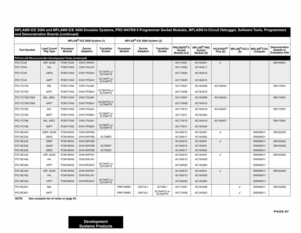
PAGE 87
PICmicr
PIC17C ✓ DM163001
PIC17C
PIC17C
PIC17C
PIC17C AC164024 DM173001
PIC17C
PIC17C AC164024 DM173001
PIC17C
PIC17C AC164027 DM173001
PIC17C
PIC17C AC164027 DM173001
PIC17C
PIC18C ✓ SW006011 DM163022
PIC18C SW006011
PIC18C ✓ SW006011 DM163022
PIC18C SW006011 DM163022
PIC18C SW006011
PIC18C ✓ SW006011 DM163022
PIC18C SW006011
PIC18C SW006011
PIC18C ✓ SW006011 DM163022
PIC18C SW006011
PIC18C SW006011
PIC18C ✓ SW006011 DM163006
PIC18C ✓ SW006011
MPLA ircuit Debugger, Software Tools, Programmers and D
Part PICSTART® Plus (5)
MPLAB® ICD 2 (6)
MPLAB® CXX Compiler
Demonstration Boards or
Evaluation Kits
NOTE:
DevelopmentSystems Products
o® Microcontroller Development Tools (continued)
44 40P, 40JW PCM17XA0 DVA17XP401 AC174001 AC164301
44 44L PCM17XA0 DVA17XL441 AC174002 AC164317
44 44PQ PCM17XA0 DVA17PQ441 XLT44PT or XLT44PT3 AC174004 AC164316
44 44PT PCM17XA0 DVA17PQ441 XLT44PT or XLT44PT3 AC174005 AC164315
752 68L PCM17XA0 DVA17XL681 AC174007 AC164308
752 64PT PCM17XA0 DVA17PQ641 XLT64PT2 or XLT64PT5 AC174008 AC164319
756/756A 68L, 68CL PCM17XA0 DVA17XL681 AC174007 AC164308
756/756A 64PT PCM17XA0 DVA17PQ641 XLT64PT2 or XLT64PT5 AC174008 AC164319
762 84L PCM17XA0 DVA17XL841 AC174012 AC164318
762 80PT PCM17XA0 DVA17PQ801 XLT80PT or XLT80PT3 AC174011 AC164320
766 84L, 84CL PCM17XA0 DVA17XL841 AC174012 AC164318
766 80PT PCM17XA0 DVA17PQ801 XLT80PT or XLT80PT3 AC174011 AC164320
242 28SP, 28JW PCM18XA0 DVA16XP282 AC164012 AC164301
242 28SO PCM18XA0 DVA16XP282 XLT28SO AC164017 AC164302
252 28SP PCM18XA0 DVA16XP282 AC164012 AC164301
252 28JW PCM18XA0 DVA16XP282 XLT28XP AC164012 AC164301
252 28SO PCM18XA0 DVA16XP282 XLT28SO AC164017 AC164302
442 40P, 40JW PCM18XA0 DVA16XP401 AC164012 AC164301
442 44L PCM18XA0 DVA16XL441 AC164013 AC164309
442 44PT PCM18XA0 DVA16PQ441 XLT44PT or XLT44PT3 AC164020 AC164305
452 40P, 40JW PCM18XA0 DVA16XP401 AC164012 AC164301
452 44L PCM18XA0 DVA16XL441 AC164013 AC164309
452 44PT PCM18XA0 DVA16PQ441 XLT44PT or XLT44PT3 AC164020 AC164305
601 68L PMF18WB1 DAF18-1 XLT68L1 AC174007 AC164308
601 64PT PMF18WB1 DAF18-1 XLT64PT2 or XLT64PT5 AC174008 AC164303
B® ICE 2000 and MPLAB® ICE 4000 Emulator Systems, PRO MATE® II Programmer Socket Modules, MPLAB® In-Cemonstration Boards (continued)
MPLAB® ICE 2000 System (1) MPLAB® ICE 4000 System (2)
Number Lead Count/Pkg Type
Processor Module
Device Adapters
Transition Socket
Processor Module
Device Adapters
Transition Socket
PRO MATE® II Socket
Module (3,4)
MPLAB® PM3Socket
Module (8)
See complete list of notes on page 94.
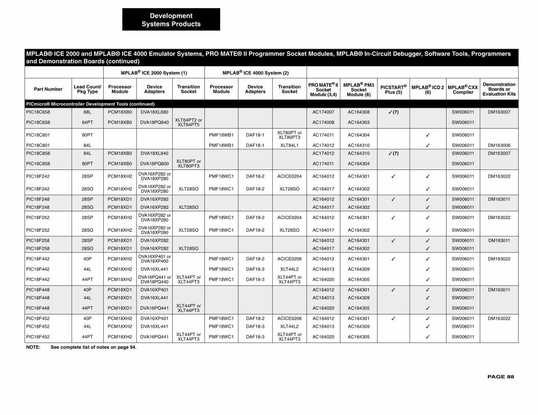
PAGE 88
PICmicr
PIC18C6 ✓ (7) SW006011 DM163007
PIC18C6 SW006011
PIC18C8 ✓ SW006011
PIC18C8 ✓ SW006011 DM163006
PIC18C8 ✓ (7) SW006011 DM163007
PIC18C8 SW006011
PIC18F2 ✓ ✓ SW006011 DM163022
PIC18F2 ✓ SW006011
PIC18F2 ✓ ✓ SW006011 DM163011
PIC18F2 ✓ SW006011
PIC18F2 ✓ ✓ SW006011 DM163022
PIC18F2 ✓ SW006011
PIC18F2 ✓ ✓ SW006011 DM163011
PIC18F2 ✓ SW006011
PIC18F4 ✓ ✓ SW006011 DM163022
PIC18F4 ✓ SW006011
PIC18F4 ✓ SW006011
PIC18F4 ✓ ✓ SW006011 DM163011
PIC18F4 ✓ SW006011
PIC18F4 ✓ SW006011
PIC18F4 ✓ ✓ SW006011 DM163022
PIC18F4 ✓ SW006011
PIC18F4 ✓ SW006011
MPLA ircuit Debugger, Software Tools, Programmers and D
Part PICSTART® Plus (5)
MPLAB® ICD 2 (6)
MPLAB® CXX Compiler
Demonstration Boards or
Evaluation Kits
NOTE:
DevelopmentSystems Products
o® Microcontroller Development Tools (continued)
58 68L PCM18XB0 DVA18XL680 AC174007 AC164308
58 64PT PCM18XB0 DVA18PQ640 XLT64PT2 or XLT64PT5 AC174008 AC164303
01 80PT PMF18WB1 DAF18-1 XLT80PT or XLT80PT3 AC174011 AC164304
01 84L PMF18WB1 DAF18-1 XLT84L1 AC174012 AC164310
58 84L PCM18XB0 DVA18XL840 AC174012 AC164310
58 80PT PCM18XB0 DVA18PQ800 XLT80PT or XLT80PT3 AC174011 AC164304
42 28SP PCM18XH2 DVA16XP282 orDVA18XP280 PMF18WC1 DAF18-2 ACICE0204 AC164012 AC164301
42 28SO PCM18XH2 DVA16XP282 orDVA18XP280 XLT28SO PMF18WC1 DAF18-2 XLT28SO AC164017 AC164302
48 28SP PCM18XD1 DVA16XP282 AC164012 AC164301
48 28SO PCM18XD1 DVA16XP282 XLT28SO AC164017 AC164302
52 28SP PCM18XH2 DVA16XP282 orDVA18XP280 PMF18WC1 DAF18-2 ACICE0204 AC164012 AC164301
52 28SO PCM18XH2 DVA16XP282 orDVA18XP280 XLT28SO PMF18WC1 DAF18-2 XLT28SO AC164017 AC164302
58 28SP PCM18XD1 DVA16XP282 AC164012 AC164301
58 28SO PCM18XD1 DVA16XP282 XLT28SO AC164017 AC164302
42 40P PCM18XH2 DVA16XP401 orDVA18XP400 PMF18WC1 DAF18-2 ACICE0206 AC164012 AC164301
42 44L PCM18XH2 DVA16XL441 PMF18WC1 DAF18-3 XLT44L2 AC164013 AC164309
42 44PT PCM18XH2 DVA16PQ441 orDVA18PQ440
XLT44PT or XLT44PT3 PMF18WC1 DAF18-3 XLT44PT or
XLT44PT3 AC164020 AC164305
48 40P PCM18XD1 DVA16XP401 AC164012 AC164301
48 44L PCM18XD1 DVA16XL441 AC164013 AC164309
48 44PT PCM18XD1 DVA16PQ441 XLT44PT or XLT44PT3 AC164020 AC164305
52 40P PCM18XH2 DVA16XP401 PMF18WC1 DAF18-2 ACICE0206 AC164012 AC164301
52 44L PCM18XH2 DVA16XL441 PMF18WC1 DAF18-3 XLT44L2 AC164013 AC164309
52 44PT PCM18XH2 DVA16PQ441 XLT44PT or XLT44PT3 PMF18WC1 DAF18-3 XLT44PT or
XLT44PT3 AC164020 AC164305
B® ICE 2000 and MPLAB® ICE 4000 Emulator Systems, PRO MATE® II Programmer Socket Modules, MPLAB® In-Cemonstration Boards (continued)
MPLAB® ICE 2000 System (1) MPLAB® ICE 4000 System (2)
Number Lead Count/Pkg Type
Processor Module
Device Adapters
Transition Socket
Processor Module
Device Adapters
Transition Socket
PRO MATE® II Socket
Module (3,4)
MPLAB® PM3Socket
Module (8)
See complete list of notes on page 94.
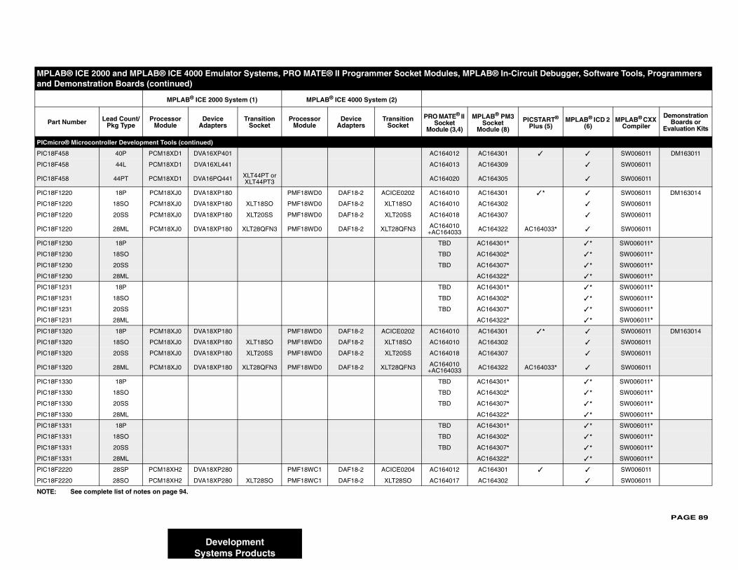
PAGE 89
PICmicr
PIC18F4 ✓ ✓ SW006011 DM163011
PIC18F4 ✓ SW006011
PIC18F4 ✓ SW006011
PIC18F1 ✓ * ✓ SW006011 DM163014
PIC18F1 ✓ SW006011
PIC18F1 ✓ SW006011
PIC18F1 AC164033* ✓ SW006011
PIC18F1 ✓ * SW006011*
PIC18F1 ✓ * SW006011*
PIC18F1 ✓ * SW006011*
PIC18F1 ✓ * SW006011*
PIC18F1 ✓ * SW006011*
PIC18F1 ✓ * SW006011*
PIC18F1 ✓ * SW006011*
PIC18F1 ✓ * SW006011*
PIC18F1 ✓ * ✓ SW006011 DM163014
PIC18F1 ✓ SW006011
PIC18F1 ✓ SW006011
PIC18F1 AC164033* ✓ SW006011
PIC18F1 ✓ * SW006011*
PIC18F1 ✓ * SW006011*
PIC18F1 ✓ * SW006011*
PIC18F1 ✓ * SW006011*
PIC18F1 ✓ * SW006011*
PIC18F1 ✓ * SW006011*
PIC18F1 ✓ * SW006011*
PIC18F1 ✓ * SW006011*
PIC18F2 ✓ ✓ SW006011
PIC18F2 ✓ SW006011
MPLA ircuit Debugger, Software Tools, Programmers and D
Part PICSTART® Plus (5)
MPLAB® ICD 2 (6)
MPLAB® CXX Compiler
Demonstration Boards or
Evaluation Kits
NOTE:
DevelopmentSystems Products
o® Microcontroller Development Tools (continued)
58 40P PCM18XD1 DVA16XP401 AC164012 AC164301
58 44L PCM18XD1 DVA16XL441 AC164013 AC164309
58 44PT PCM18XD1 DVA16PQ441 XLT44PT or XLT44PT3 AC164020 AC164305
220 18P PCM18XJ0 DVA18XP180 PMF18WD0 DAF18-2 ACICE0202 AC164010 AC164301
220 18SO PCM18XJ0 DVA18XP180 XLT18SO PMF18WD0 DAF18-2 XLT18SO AC164010 AC164302
220 20SS PCM18XJ0 DVA18XP180 XLT20SS PMF18WD0 DAF18-2 XLT20SS AC164018 AC164307
220 28ML PCM18XJ0 DVA18XP180 XLT28QFN3 PMF18WD0 DAF18-2 XLT28QFN3 AC164010+AC164033 AC164322
230 18P TBD AC164301*
230 18SO TBD AC164302*
230 20SS TBD AC164307*
230 28ML AC164322*
231 18P TBD AC164301*
231 18SO TBD AC164302*
231 20SS TBD AC164307*
231 28ML AC164322*
320 18P PCM18XJ0 DVA18XP180 PMF18WD0 DAF18-2 ACICE0202 AC164010 AC164301
320 18SO PCM18XJ0 DVA18XP180 XLT18SO PMF18WD0 DAF18-2 XLT18SO AC164010 AC164302
320 20SS PCM18XJ0 DVA18XP180 XLT20SS PMF18WD0 DAF18-2 XLT20SS AC164018 AC164307
320 28ML PCM18XJ0 DVA18XP180 XLT28QFN3 PMF18WD0 DAF18-2 XLT28QFN3 AC164010+AC164033 AC164322
330 18P TBD AC164301*
330 18SO TBD AC164302*
330 20SS TBD AC164307*
330 28ML AC164322*
331 18P TBD AC164301*
331 18SO TBD AC164302*
331 20SS TBD AC164307*
331 28ML AC164322*
220 28SP PCM18XH2 DVA18XP280 PMF18WC1 DAF18-2 ACICE0204 AC164012 AC164301
220 28SO PCM18XH2 DVA18XP280 XLT28SO PMF18WC1 DAF18-2 XLT28SO AC164017 AC164302
B® ICE 2000 and MPLAB® ICE 4000 Emulator Systems, PRO MATE® II Programmer Socket Modules, MPLAB® In-Cemonstration Boards (continued)
MPLAB® ICE 2000 System (1) MPLAB® ICE 4000 System (2)
Number Lead Count/Pkg Type
Processor Module
Device Adapters
Transition Socket
Processor Module
Device Adapters
Transition Socket
PRO MATE® II Socket
Module (3,4)
MPLAB® PM3Socket
Module (8)
See complete list of notes on page 94.
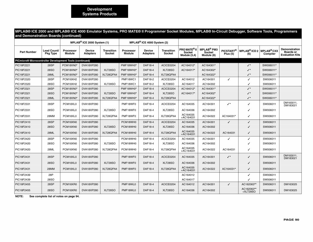
PAGE 90
PICmicr
PIC18F2 ✓ * SW006011*
PIC18F2 ✓ * SW006011*
PIC18F2 ✓ * SW006011*
PIC18F2 ✓ ✓ SW006011
PIC18F2 ✓ SW006011
PIC18F2 ✓ * SW006011*
PIC18F2 ✓ * SW006011*
PIC18F2 ✓ * SW006011*
PIC18F2 ✓ * ✓ SW006011 DM183011, DM183021
PIC18F2 ✓ SW006011
PIC18F2 AC164031* ✓ SW006011
PIC18F2 ✓ ✓ SW006011
PIC18F2 ✓ SW006011
PIC18F2 AC164031 ✓ SW006011
PIC18F2 ✓ ✓ SW006011
PIC18F2 ✓ SW006011
PIC18F2 AC164031 ✓ SW006011
PIC18F2 ✓ * ✓ SW006011 DM183011, DM183021
PIC18F2 ✓ SW006011
PIC18F2 AC164031* ✓ SW006011
PIC18F2 ✓ SW006011
PIC18F2 ✓ SW006011
PIC18F2 ✓ AC162063** SW006011 DM163025
PIC18F2 AC162063**+XLT28SO SW006011 DM163025
MPLA ircuit Debugger, Software Tools, Programmers and D
Part PICSTART® Plus (5)
MPLAB® ICD 2 (6)
MPLAB® CXX Compiler
Demonstration Boards or
Evaluation Kits
NOTE:
DevelopmentSystems Products
o® Microcontroller Development Tools (continued)
221 28SP PCM18XN0* DVA18XP280 PMF18WH0* DAF18-4 ACICE0204 AC164012* AC164301*
221 28SO PCM18XN0* DVA18XP280 XLT28SO PMF18WH0* DAF18-4 XLT28SO AC164017* AC164302*
221 28ML PCM18XN0* DVA18XP280 XLT28QFN4 PMF18WH0* DAF18-4 XLT28QFN4 AC164322*
320 28SP PCM18XH2 DVA18XP280 PMF18WC1 DAF18-2 ACICE0204 AC164012 AC164301
320 28SO PCM18XH2 DVA18XP280 XLT28SO PMF18WC1 DAF18-2 XLT28SO AC164017 AC164302
321 28SP PCM18XN0* DVA18XP280 PMF18WH0* DAF18-4 ACICE0204 AC164012* AC164301*
321 28SO PCM18XN0* DVA18XP280 XLT28SO PMF18WH0* DAF18-4 XLT28SO AC164017* AC164302*
321 28ML PCM18XN0* DVA18XP280 XLT28QFN4 PMF18WH0* DAF18-4 XLT28QFN4 AC164322*
331 28SP PCM18XL0 DVA18XP280 PMF18WF0 DAF18-4 ACICE0204 AC164035 AC164301
331 28SO PCM18XL0 DVA18XP280 XLT28SO PMF18WF0 DAF18-4 XLT28SO AC164036 AC164302
331 28MM PCM18XL0 DVA18XP280 XLT28QFN4 PMF18WF0 DAF18-4 XLT28QFN4 AC164035 +AC164031 AC164322
410 28SP PCM18XN0 DVA18XP280 PCM18WH0 DAF18-4 ACICE0204 AC164035 AC164301
410 28SO PCM18XN0 DVA18XP280 XLT28SO PCM18WH0 DAF18-4 XLT28SO AC164036 AC164302
410 28ML PCM18XN0 DVA18XP280 XLT28QFN4 PCM18WH0 DAF18-4 XLT28QFN4 AC164035 +AC164031 AC164322
420 28SP PCM18XN0 DVA18XP280 PCM18WH0 DAF18-4 ACICE0204 AC164035 AC164301
420 28SO PCM18XN0 DVA18XP280 XLT28SO PCM18WH0 DAF18-4 XLT28SO AC164036 AC164302
420 28ML PCM18XN0 DVA18XP280 XLT28QFN4 PCM18WH0 DAF18-4 XLT28QFN4 AC164035 +AC164031 AC164322
431 28SP PCM18XL0 DVA18XP280 PMF18WF0 DAF18-4 ACICE0204 AC164035 AC164301
431 28SO PCM18XL0 DVA18XP280 XLT28SO PMF18WF0 DAF18-4 XLT28SO AC164036 AC164302
431 28MM PCM18XL0 DVA18XP280 XLT28QFN4 PMF18WF0 DAF18-4 XLT28QFN4 AC164035 +AC164031 AC164322
439 28P AC164012
439 28SO AC164017
455 28SP PCM18XR0 DVA18XP280 PMF18WL0 DAF18-4 ACICE0204 AC164012 AC164301
455 28SO PCM18XR0 DVA18XP280 XLT28SO PMF18WL0 DAF18-4 XLT28SO AC164036 AC164302
B® ICE 2000 and MPLAB® ICE 4000 Emulator Systems, PRO MATE® II Programmer Socket Modules, MPLAB® In-Cemonstration Boards (continued)
MPLAB® ICE 2000 System (1) MPLAB® ICE 4000 System (2)
Number Lead Count/Pkg Type
Processor Module
Device Adapters
Transition Socket
Processor Module
Device Adapters
Transition Socket
PRO MATE® II Socket
Module (3,4)
MPLAB® PM3Socket
Module (8)
See complete list of notes on page 94.
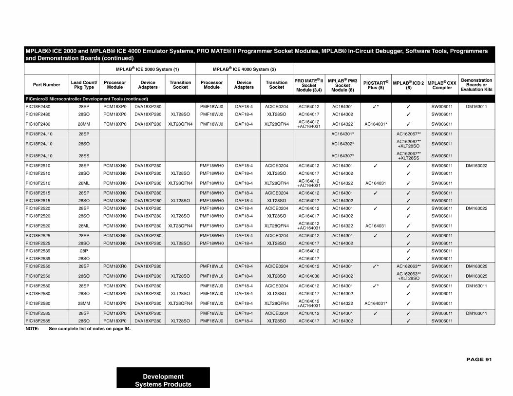
PAGE 91
PICmicr
PIC18F2 ✓ * ✓ SW006011 DM163011
PIC18F2 ✓ SW006011
PIC18F2 AC164031* ✓ SW006011
PIC18F2 AC162067** SW006011
PIC18F2 AC162067** +XLT28SO SW006011
PIC18F2 AC162067** +XLT28SS SW006011
PIC18F2 ✓ ✓ SW006011 DM163022
PIC18F2 ✓ SW006011
PIC18F2 AC164031 ✓ SW006011
PIC18F2 ✓ ✓ SW006011
PIC18F2 ✓ SW006011
PIC18F2 ✓ ✓ SW006011 DM163022
PIC18F2 ✓ SW006011
PIC18F2 AC164031 ✓ SW006011
PIC18F2 ✓ ✓ SW006011
PIC18F2 ✓ SW006011
PIC18F2 ✓ SW006011
PIC18F2 ✓ SW006011
PIC18F2 ✓ * AC162063** SW006011 DM163025
PIC18F2 AC162063**+XLT28SO SW006011 DM163025
PIC18F2 ✓ * ✓ SW006011 DM163011
PIC18F2 ✓ SW006011
PIC18F2 AC164031* ✓ SW006011
PIC18F2 ✓ ✓ SW006011 DM163011
PIC18F2 ✓ SW006011
MPLA ircuit Debugger, Software Tools, Programmers and D
Part PICSTART® Plus (5)
MPLAB® ICD 2 (6)
MPLAB® CXX Compiler
Demonstration Boards or
Evaluation Kits
NOTE:
DevelopmentSystems Products
o® Microcontroller Development Tools (continued)
480 28SP PCM18XP0 DVA18XP280 PMF18WJ0 DAF18-4 ACICE0204 AC164012 AC164301
480 28SO PCM18XP0 DVA18XP280 XLT28SO PMF18WJ0 DAF18-4 XLT28SO AC164017 AC164302
480 28MM PCM18XP0 DVA18XP280 XLT28QFN4 PMF18WJ0 DAF18-4 XLT28QFN4 AC164012 +AC164031 AC164322
4J10 28SP AC164301*
4J10 28SO AC164302*
4J10 28SS AC164307*
510 28SP PCM18XN0 DVA18XP280 PMF18WH0 DAF18-4 ACICE0204 AC164012 AC164301
510 28SO PCM18XN0 DVA18XP280 XLT28SO PMF18WH0 DAF18-4 XLT28SO AC164017 AC164302
510 28ML PCM18XN0 DVA18XP280 XLT28QFN4 PMF18WH0 DAF18-4 XLT28QFN4 AC164012 +AC164031 AC164322
515 28SP PCM18XN0 DVA18XP280 PMF18WH0 DAF18-4 ACICE0204 AC164012 AC164301
515 28SO PCM18XN0 DVA18CP280 XLT28SO PMF18WH0 DAF18-4 XLT28SO AC164017 AC164302
520 28SP PCM18XN0 DVA18XP280 PMF18WH0 DAF18-4 ACICE0204 AC164012 AC164301
520 28SO PCM18XN0 DVA18XP280 XLT28SO PMF18WH0 DAF18-4 XLT28SO AC164017 AC164302
520 28ML PCM18XN0 DVA18XP280 XLT28QFN4 PMF18WH0 DAF18-4 XLT28QFN4 AC164012 +AC164031 AC164322
525 28SP PCM18XN0 DVA18XP280 PMF18WH0 DAF18-4 ACICE0204 AC164012 AC164301
525 28SO PCM18XN0 DVA18XP280 XLT28SO PMF18WH0 DAF18-4 XLT28SO AC164017 AC164302
539 28P AC164012
539 28SO AC164017
550 28SP PCM18XR0 DVA18XP280 PMF18WL0 DAF18-4 ACICE0204 AC164012 AC164301
550 28SO PCM18XR0 DVA18XP280 XLT28SO PMF18WL0 DAF18-4 XLT28SO AC164036 AC164302
580 28SP PCM18XP0 DVA18XP280 PMF18WJ0 DAF18-4 ACICE0204 AC164012 AC164301
580 28SO PCM18XP0 DVA18XP280 XLT28SO PMF18WJ0 DAF18-4 XLT28SO AC164017 AC164302
580 28MM PCM18XP0 DVA18XP280 XLT28QFN4 PMF18WJ0 DAF18-4 XLT28QFN4 AC164012 +AC164031 AC164322
585 28SP PCM18XP0 DVA18XP280 PMF18WJ0 DAF18-4 ACICE0204 AC164012 AC164301
585 28SO PCM18XP0 DVA18XP280 XLT28SO PMF18WJ0 DAF18-4 XLT28SO AC164017 AC164302
B® ICE 2000 and MPLAB® ICE 4000 Emulator Systems, PRO MATE® II Programmer Socket Modules, MPLAB® In-Cemonstration Boards (continued)
MPLAB® ICE 2000 System (1) MPLAB® ICE 4000 System (2)
Number Lead Count/Pkg Type
Processor Module
Device Adapters
Transition Socket
Processor Module
Device Adapters
Transition Socket
PRO MATE® II Socket
Module (3,4)
MPLAB® PM3Socket
Module (8)
See complete list of notes on page 94.
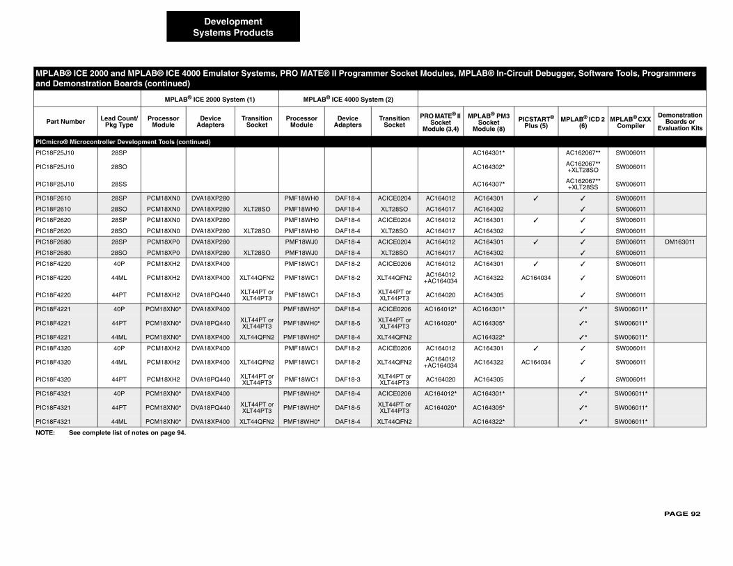
PAGE 92
PICmicr
PIC18F2 AC162067** SW006011
PIC18F2 AC162067** +XLT28SO SW006011
PIC18F2 AC162067** +XLT28SS SW006011
PIC18F2 ✓ ✓ SW006011
PIC18F2 ✓ SW006011
PIC18F2 ✓ ✓ SW006011
PIC18F2 ✓ SW006011
PIC18F2 ✓ ✓ SW006011 DM163011
PIC18F2 ✓ SW006011
PIC18F4 ✓ ✓ SW006011
PIC18F4 AC164034 ✓ SW006011
PIC18F4 ✓ SW006011
PIC18F4 ✓ * SW006011*
PIC18F4 ✓ * SW006011*
PIC18F4 ✓ * SW006011*
PIC18F4 ✓ ✓ SW006011
PIC18F4 AC164034 ✓ SW006011
PIC18F4 ✓ SW006011
PIC18F4 ✓ * SW006011*
PIC18F4 ✓ * SW006011*
PIC18F4 ✓ * SW006011*
MPLA ircuit Debugger, Software Tools, Programmers and D
Part PICSTART® Plus (5)
MPLAB® ICD 2 (6)
MPLAB® CXX Compiler
Demonstration Boards or
Evaluation Kits
NOTE:
DevelopmentSystems Products
o® Microcontroller Development Tools (continued)
5J10 28SP AC164301*
5J10 28SO AC164302*
5J10 28SS AC164307*
610 28SP PCM18XN0 DVA18XP280 PMF18WH0 DAF18-4 ACICE0204 AC164012 AC164301
610 28SO PCM18XN0 DVA18XP280 XLT28SO PMF18WH0 DAF18-4 XLT28SO AC164017 AC164302
620 28SP PCM18XN0 DVA18XP280 PMF18WH0 DAF18-4 ACICE0204 AC164012 AC164301
620 28SO PCM18XN0 DVA18XP280 XLT28SO PMF18WH0 DAF18-4 XLT28SO AC164017 AC164302
680 28SP PCM18XP0 DVA18XP280 PMF18WJ0 DAF18-4 ACICE0204 AC164012 AC164301
680 28SO PCM18XP0 DVA18XP280 XLT28SO PMF18WJ0 DAF18-4 XLT28SO AC164017 AC164302
220 40P PCM18XH2 DVA18XP400 PMF18WC1 DAF18-2 ACICE0206 AC164012 AC164301
220 44ML PCM18XH2 DVA18XP400 XLT44QFN2 PMF18WC1 DAF18-2 XLT44QFN2 AC164012+AC164034 AC164322
220 44PT PCM18XH2 DVA18PQ440 XLT44PT or XLT44PT3 PMF18WC1 DAF18-3 XLT44PT or
XLT44PT3 AC164020 AC164305
221 40P PCM18XN0* DVA18XP400 PMF18WH0* DAF18-4 ACICE0206 AC164012* AC164301*
221 44PT PCM18XN0* DVA18PQ440 XLT44PT or XLT44PT3 PMF18WH0* DAF18-5 XLT44PT or
XLT44PT3 AC164020* AC164305*
221 44ML PCM18XN0* DVA18XP400 XLT44QFN2 PMF18WH0* DAF18-4 XLT44QFN2 AC164322*
320 40P PCM18XH2 DVA18XP400 PMF18WC1 DAF18-2 ACICE0206 AC164012 AC164301
320 44ML PCM18XH2 DVA18XP400 XLT44QFN2 PMF18WC1 DAF18-2 XLT44QFN2 AC164012+AC164034 AC164322
320 44PT PCM18XH2 DVA18PQ440 XLT44PT or XLT44PT3 PMF18WC1 DAF18-3 XLT44PT or
XLT44PT3 AC164020 AC164305
321 40P PCM18XN0* DVA18XP400 PMF18WH0* DAF18-4 ACICE0206 AC164012* AC164301*
321 44PT PCM18XN0* DVA18PQ440 XLT44PT or XLT44PT3 PMF18WH0* DAF18-5 XLT44PT or
XLT44PT3 AC164020* AC164305*
321 44ML PCM18XN0* DVA18XP400 XLT44QFN2 PMF18WH0* DAF18-4 XLT44QFN2 AC164322*
B® ICE 2000 and MPLAB® ICE 4000 Emulator Systems, PRO MATE® II Programmer Socket Modules, MPLAB® In-Cemonstration Boards (continued)
MPLAB® ICE 2000 System (1) MPLAB® ICE 4000 System (2)
Number Lead Count/Pkg Type
Processor Module
Device Adapters
Transition Socket
Processor Module
Device Adapters
Transition Socket
PRO MATE® II Socket
Module (3,4)
MPLAB® PM3Socket
Module (8)
See complete list of notes on page 94.
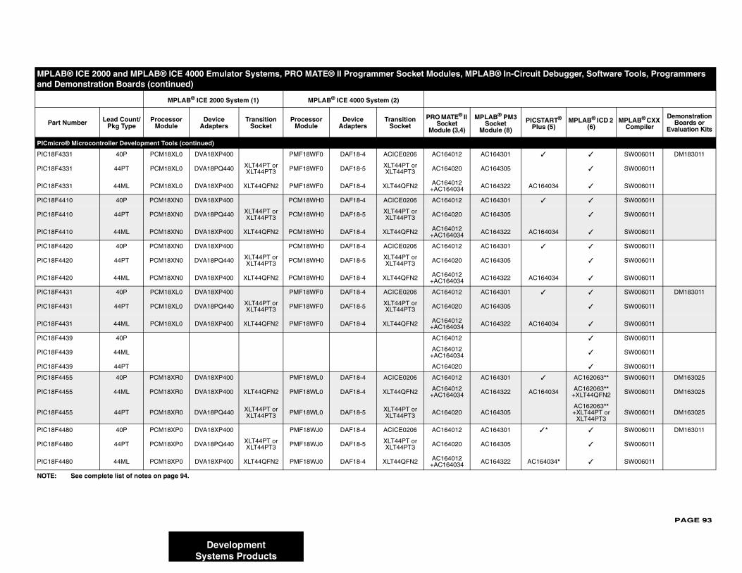
PAGE 93
PICmicr
PIC18F4 ✓ ✓ SW006011 DM183011
PIC18F4 ✓ SW006011
PIC18F4 AC164034 ✓ SW006011
PIC18F4 ✓ ✓ SW006011
PIC18F4 ✓ SW006011
PIC18F4 AC164034 ✓ SW006011
PIC18F4 ✓ ✓ SW006011
PIC18F4 ✓ SW006011
PIC18F4 AC164034 ✓ SW006011
PIC18F4 ✓ ✓ SW006011 DM183011
PIC18F4 ✓ SW006011
PIC18F4 AC164034 ✓ SW006011
PIC18F4 ✓ SW006011
PIC18F4 ✓ SW006011
PIC18F4 ✓ SW006011
PIC18F4 ✓ AC162063** SW006011 DM163025
PIC18F4 AC164034 AC162063**+XLT44QFN2 SW006011 DM163025
PIC18F4AC162063**+XLT44PT or
XLT44PT3SW006011 DM163025
PIC18F4 ✓ * ✓ SW006011 DM163011
PIC18F4 ✓ SW006011
PIC18F4 AC164034* ✓ SW006011
MPLA ircuit Debugger, Software Tools, Programmers and D
Part PICSTART® Plus (5)
MPLAB® ICD 2 (6)
MPLAB® CXX Compiler
Demonstration Boards or
Evaluation Kits
NOTE:
DevelopmentSystems Products
o® Microcontroller Development Tools (continued)
331 40P PCM18XL0 DVA18XP400 PMF18WF0 DAF18-4 ACICE0206 AC164012 AC164301
331 44PT PCM18XL0 DVA18PQ440 XLT44PT or XLT44PT3 PMF18WF0 DAF18-5 XLT44PT or
XLT44PT3 AC164020 AC164305
331 44ML PCM18XL0 DVA18XP400 XLT44QFN2 PMF18WF0 DAF18-4 XLT44QFN2 AC164012+AC164034 AC164322
410 40P PCM18XN0 DVA18XP400 PCM18WH0 DAF18-4 ACICE0206 AC164012 AC164301
410 44PT PCM18XN0 DVA18PQ440 XLT44PT or XLT44PT3 PCM18WH0 DAF18-5 XLT44PT or
XLT44PT3 AC164020 AC164305
410 44ML PCM18XN0 DVA18XP400 XLT44QFN2 PCM18WH0 DAF18-4 XLT44QFN2 AC164012 +AC164034 AC164322
420 40P PCM18XN0 DVA18XP400 PCM18WH0 DAF18-4 ACICE0206 AC164012 AC164301
420 44PT PCM18XN0 DVA18PQ440 XLT44PT or XLT44PT3 PCM18WH0 DAF18-5 XLT44PT or
XLT44PT3 AC164020 AC164305
420 44ML PCM18XN0 DVA18XP400 XLT44QFN2 PCM18WH0 DAF18-4 XLT44QFN2 AC164012 +AC164034 AC164322
431 40P PCM18XL0 DVA18XP400 PMF18WF0 DAF18-4 ACICE0206 AC164012 AC164301
431 44PT PCM18XL0 DVA18PQ440 XLT44PT or XLT44PT3 PMF18WF0 DAF18-5 XLT44PT or
XLT44PT3 AC164020 AC164305
431 44ML PCM18XL0 DVA18XP400 XLT44QFN2 PMF18WF0 DAF18-4 XLT44QFN2 AC164012+AC164034 AC164322
439 40P AC164012
439 44ML AC164012+AC164034
439 44PT AC164020
455 40P PCM18XR0 DVA18XP400 PMF18WL0 DAF18-4 ACICE0206 AC164012 AC164301
455 44ML PCM18XR0 DVA18XP400 XLT44QFN2 PMF18WL0 DAF18-4 XLT44QFN2 AC164012 +AC164034 AC164322
455 44PT PCM18XR0 DVA18PQ440 XLT44PT or XLT44PT3 PMF18WL0 DAF18-5 XLT44PT or
XLT44PT3 AC164020 AC164305
480 40P PCM18XP0 DVA18XP400 PMF18WJ0 DAF18-4 ACICE0206 AC164012 AC164301
480 44PT PCM18XP0 DVA18PQ440 XLT44PT or XLT44PT3 PMF18WJ0 DAF18-5 XLT44PT or
XLT44PT3 AC164020 AC164305
480 44ML PCM18XP0 DVA18XP400 XLT44QFN2 PMF18WJ0 DAF18-4 XLT44QFN2 AC164012 +AC164034 AC164322
B® ICE 2000 and MPLAB® ICE 4000 Emulator Systems, PRO MATE® II Programmer Socket Modules, MPLAB® In-Cemonstration Boards (continued)
MPLAB® ICE 2000 System (1) MPLAB® ICE 4000 System (2)
Number Lead Count/Pkg Type
Processor Module
Device Adapters
Transition Socket
Processor Module
Device Adapters
Transition Socket
PRO MATE® II Socket
Module (3,4)
MPLAB® PM3Socket
Module (8)
See complete list of notes on page 94.
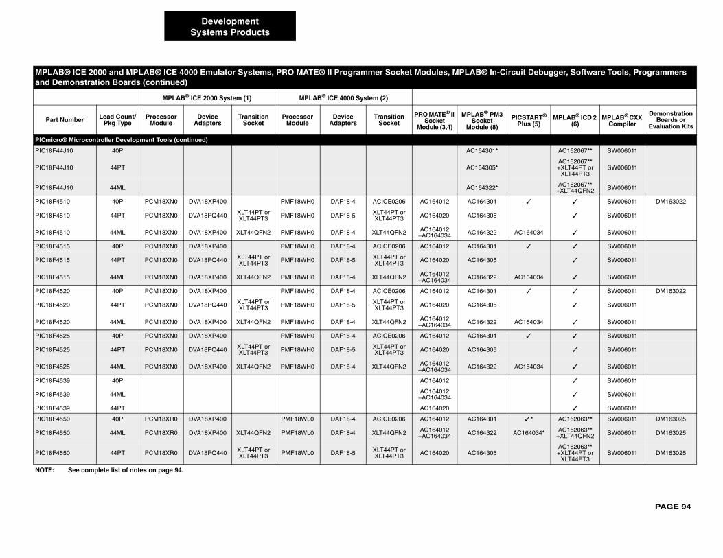
PAGE 94
PICmicr
PIC18F4 AC162067** SW006011
PIC18F4AC162067** +XLT44PT or
XLT44PT3SW006011
PIC18F4 AC162067** +XLT44QFN2 SW006011
PIC18F4 ✓ ✓ SW006011 DM163022
PIC18F4 ✓ SW006011
PIC18F4 AC164034 ✓ SW006011
PIC18F4 ✓ ✓ SW006011
PIC18F4 ✓ SW006011
PIC18F4 AC164034 ✓ SW006011
PIC18F4 ✓ ✓ SW006011 DM163022
PIC18F4 ✓ SW006011
PIC18F4 AC164034 ✓ SW006011
PIC18F4 ✓ ✓ SW006011
PIC18F4 ✓ SW006011
PIC18F4 AC164034 ✓ SW006011
PIC18F4 ✓ SW006011
PIC18F4 ✓ SW006011
PIC18F4 ✓ SW006011
PIC18F4 ✓ * AC162063** SW006011 DM163025
PIC18F4 AC164034* AC162063**+XLT44QFN2 SW006011 DM163025
PIC18F4AC162063**+XLT44PT or
XLT44PT3SW006011 DM163025
MPLA ircuit Debugger, Software Tools, Programmers and D
Part PICSTART® Plus (5)
MPLAB® ICD 2 (6)
MPLAB® CXX Compiler
Demonstration Boards or
Evaluation Kits
NOTE:
DevelopmentSystems Products
o® Microcontroller Development Tools (continued)
4J10 40P AC164301*
4J10 44PT AC164305*
4J10 44ML AC164322*
510 40P PCM18XN0 DVA18XP400 PMF18WH0 DAF18-4 ACICE0206 AC164012 AC164301
510 44PT PCM18XN0 DVA18PQ440 XLT44PT or XLT44PT3 PMF18WH0 DAF18-5 XLT44PT or
XLT44PT3 AC164020 AC164305
510 44ML PCM18XN0 DVA18XP400 XLT44QFN2 PMF18WH0 DAF18-4 XLT44QFN2 AC164012 +AC164034 AC164322
515 40P PCM18XN0 DVA18XP400 PMF18WH0 DAF18-4 ACICE0206 AC164012 AC164301
515 44PT PCM18XN0 DVA18PQ440 XLT44PT or XLT44PT3 PMF18WH0 DAF18-5 XLT44PT or
XLT44PT3 AC164020 AC164305
515 44ML PCM18XN0 DVA18XP400 XLT44QFN2 PMF18WH0 DAF18-4 XLT44QFN2 AC164012+AC164034 AC164322
520 40P PCM18XN0 DVA18XP400 PMF18WH0 DAF18-4 ACICE0206 AC164012 AC164301
520 44PT PCM18XN0 DVA18PQ440 XLT44PT or XLT44PT3 PMF18WH0 DAF18-5 XLT44PT or
XLT44PT3 AC164020 AC164305
520 44ML PCM18XN0 DVA18XP400 XLT44QFN2 PMF18WH0 DAF18-4 XLT44QFN2 AC164012 +AC164034 AC164322
525 40P PCM18XN0 DVA18XP400 PMF18WH0 DAF18-4 ACICE0206 AC164012 AC164301
525 44PT PCM18XN0 DVA18PQ440 XLT44PT or XLT44PT3 PMF18WH0 DAF18-5 XLT44PT or
XLT44PT3 AC164020 AC164305
525 44ML PCM18XN0 DVA18XP400 XLT44QFN2 PMF18WH0 DAF18-4 XLT44QFN2 AC164012+AC164034 AC164322
539 40P AC164012
539 44ML AC164012+AC164034
539 44PT AC164020
550 40P PCM18XR0 DVA18XP400 PMF18WL0 DAF18-4 ACICE0206 AC164012 AC164301
550 44ML PCM18XR0 DVA18XP400 XLT44QFN2 PMF18WL0 DAF18-4 XLT44QFN2 AC164012 +AC164034 AC164322
550 44PT PCM18XR0 DVA18PQ440 XLT44PT or XLT44PT3 PMF18WL0 DAF18-5 XLT44PT or
XLT44PT3 AC164020 AC164305
B® ICE 2000 and MPLAB® ICE 4000 Emulator Systems, PRO MATE® II Programmer Socket Modules, MPLAB® In-Cemonstration Boards (continued)
MPLAB® ICE 2000 System (1) MPLAB® ICE 4000 System (2)
Number Lead Count/Pkg Type
Processor Module
Device Adapters
Transition Socket
Processor Module
Device Adapters
Transition Socket
PRO MATE® II Socket
Module (3,4)
MPLAB® PM3Socket
Module (8)
See complete list of notes on page 94.
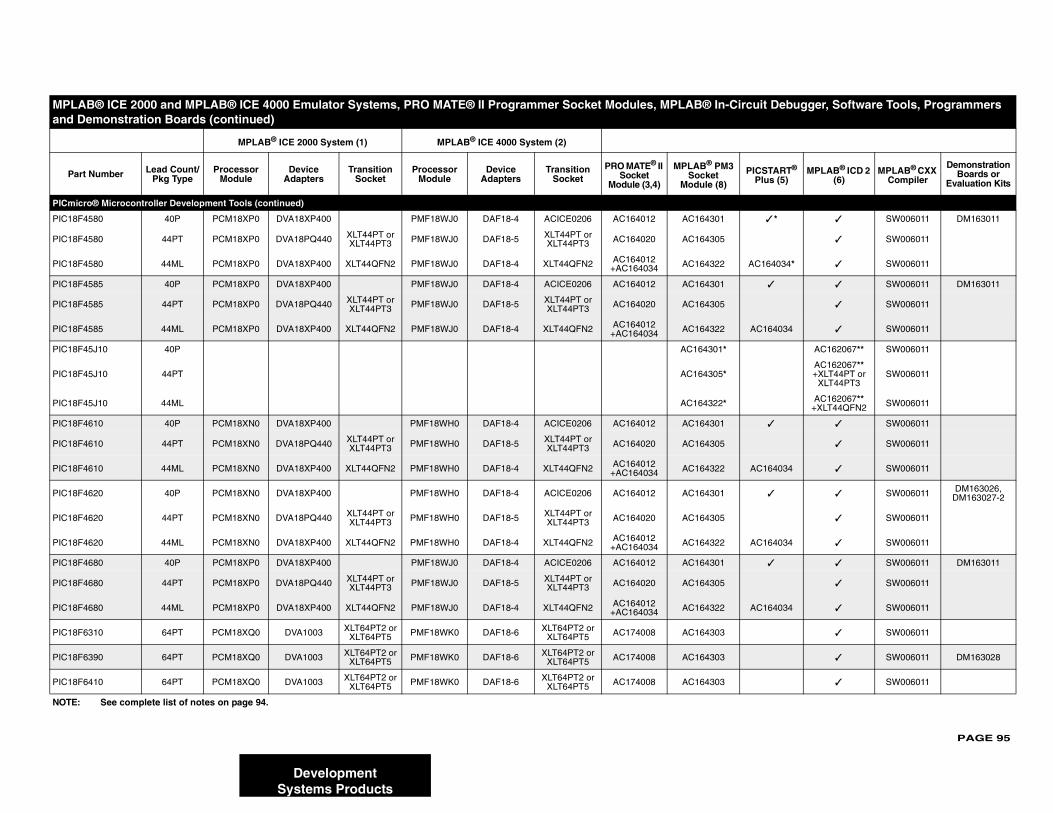
PAGE 95
PICmicr
PIC18F4 ✓ * ✓ SW006011 DM163011
PIC18F4 ✓ SW006011
PIC18F4 AC164034* ✓ SW006011
PIC18F4 ✓ ✓ SW006011 DM163011
PIC18F4 ✓ SW006011
PIC18F4 AC164034 ✓ SW006011
PIC18F4 AC162067** SW006011
PIC18F4AC162067** +XLT44PT or
XLT44PT3SW006011
PIC18F4 AC162067** +XLT44QFN2 SW006011
PIC18F4 ✓ ✓ SW006011
PIC18F4 ✓ SW006011
PIC18F4 AC164034 ✓ SW006011
PIC18F4 ✓ ✓ SW006011 DM163026, DM163027-2
PIC18F4 ✓ SW006011
PIC18F4 AC164034 ✓ SW006011
PIC18F4 ✓ ✓ SW006011 DM163011
PIC18F4 ✓ SW006011
PIC18F4 AC164034 ✓ SW006011
PIC18F6 ✓ SW006011
PIC18F6 ✓ SW006011 DM163028
PIC18F6 ✓ SW006011
MPLA ircuit Debugger, Software Tools, Programmers and D
Part PICSTART® Plus (5)
MPLAB® ICD 2 (6)
MPLAB® CXX Compiler
Demonstration Boards or
Evaluation Kits
NOTE:
DevelopmentSystems Products
o® Microcontroller Development Tools (continued)
580 40P PCM18XP0 DVA18XP400 PMF18WJ0 DAF18-4 ACICE0206 AC164012 AC164301
580 44PT PCM18XP0 DVA18PQ440 XLT44PT or XLT44PT3 PMF18WJ0 DAF18-5 XLT44PT or
XLT44PT3 AC164020 AC164305
580 44ML PCM18XP0 DVA18XP400 XLT44QFN2 PMF18WJ0 DAF18-4 XLT44QFN2 AC164012 +AC164034 AC164322
585 40P PCM18XP0 DVA18XP400 PMF18WJ0 DAF18-4 ACICE0206 AC164012 AC164301
585 44PT PCM18XP0 DVA18PQ440 XLT44PT or XLT44PT3 PMF18WJ0 DAF18-5 XLT44PT or
XLT44PT3 AC164020 AC164305
585 44ML PCM18XP0 DVA18XP400 XLT44QFN2 PMF18WJ0 DAF18-4 XLT44QFN2 AC164012+AC164034 AC164322
5J10 40P AC164301*
5J10 44PT AC164305*
5J10 44ML AC164322*
610 40P PCM18XN0 DVA18XP400 PMF18WH0 DAF18-4 ACICE0206 AC164012 AC164301
610 44PT PCM18XN0 DVA18PQ440 XLT44PT or XLT44PT3 PMF18WH0 DAF18-5 XLT44PT or
XLT44PT3 AC164020 AC164305
610 44ML PCM18XN0 DVA18XP400 XLT44QFN2 PMF18WH0 DAF18-4 XLT44QFN2 AC164012+AC164034 AC164322
620 40P PCM18XN0 DVA18XP400 PMF18WH0 DAF18-4 ACICE0206 AC164012 AC164301
620 44PT PCM18XN0 DVA18PQ440 XLT44PT or XLT44PT3 PMF18WH0 DAF18-5 XLT44PT or
XLT44PT3 AC164020 AC164305
620 44ML PCM18XN0 DVA18XP400 XLT44QFN2 PMF18WH0 DAF18-4 XLT44QFN2 AC164012+AC164034 AC164322
680 40P PCM18XP0 DVA18XP400 PMF18WJ0 DAF18-4 ACICE0206 AC164012 AC164301
680 44PT PCM18XP0 DVA18PQ440 XLT44PT or XLT44PT3 PMF18WJ0 DAF18-5 XLT44PT or
XLT44PT3 AC164020 AC164305
680 44ML PCM18XP0 DVA18XP400 XLT44QFN2 PMF18WJ0 DAF18-4 XLT44QFN2 AC164012+AC164034 AC164322
310 64PT PCM18XQ0 DVA1003 XLT64PT2 or XLT64PT5 PMF18WK0 DAF18-6 XLT64PT2 or
XLT64PT5 AC174008 AC164303
390 64PT PCM18XQ0 DVA1003 XLT64PT2 or XLT64PT5 PMF18WK0 DAF18-6 XLT64PT2 or
XLT64PT5 AC174008 AC164303
410 64PT PCM18XQ0 DVA1003 XLT64PT2 or XLT64PT5 PMF18WK0 DAF18-6 XLT64PT2 or
XLT64PT5 AC174008 AC164303
B® ICE 2000 and MPLAB® ICE 4000 Emulator Systems, PRO MATE® II Programmer Socket Modules, MPLAB® In-Cemonstration Boards (continued)
MPLAB® ICE 2000 System (1) MPLAB® ICE 4000 System (2)
Number Lead Count/Pkg Type
Processor Module
Device Adapters
Transition Socket
Processor Module
Device Adapters
Transition Socket
PRO MATE® II Socket
Module (3,4)
MPLAB® PM3Socket
Module (8)
See complete list of notes on page 94.
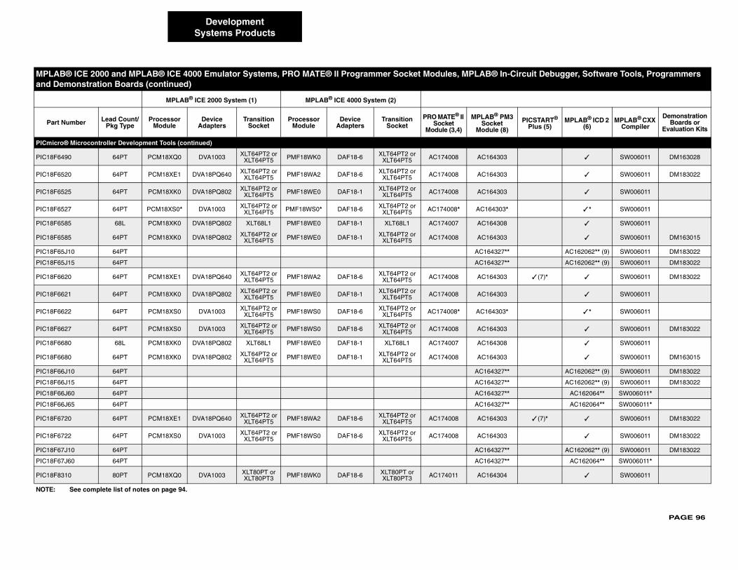
PAGE 96
PICmicr
PIC18F6 ✓ SW006011 DM163028
PIC18F6 ✓ SW006011 DM183022
PIC18F6 ✓ SW006011
PIC18F6 ✓ * SW006011
PIC18F6 ✓ SW006011
PIC18F6 ✓ SW006011 DM163015
PIC18F6 AC162062** (9) SW006011 DM183022
PIC18F6 AC162062** (9) SW006011 DM183022
PIC18F6 ✓ (7)* ✓ SW006011 DM183022
PIC18F6 ✓ SW006011
PIC18F6 ✓ * SW006011
PIC18F6 ✓ SW006011 DM183022
PIC18F6 ✓ SW006011
PIC18F6 ✓ SW006011 DM163015
PIC18F6 AC162062** (9) SW006011 DM183022
PIC18F6 AC162062** (9) SW006011 DM183022
PIC18F6 AC162064** SW006011*
PIC18F6 AC162064** SW006011*
PIC18F6 ✓ (7)* ✓ SW006011 DM183022
PIC18F6 ✓ SW006011 DM183022
PIC18F6 AC162062** (9) SW006011 DM183022
PIC18F6 AC162064** SW006011*
PIC18F8 ✓ SW006011
MPLA ircuit Debugger, Software Tools, Programmers and D
Part PICSTART® Plus (5)
MPLAB® ICD 2 (6)
MPLAB® CXX Compiler
Demonstration Boards or
Evaluation Kits
NOTE:
DevelopmentSystems Products
o® Microcontroller Development Tools (continued)
490 64PT PCM18XQ0 DVA1003 XLT64PT2 or XLT64PT5 PMF18WK0 DAF18-6 XLT64PT2 or
XLT64PT5 AC174008 AC164303
520 64PT PCM18XE1 DVA18PQ640 XLT64PT2 or XLT64PT5 PMF18WA2 DAF18-6 XLT64PT2 or
XLT64PT5 AC174008 AC164303
525 64PT PCM18XK0 DVA18PQ802 XLT64PT2 or XLT64PT5 PMF18WE0 DAF18-1 XLT64PT2 or
XLT64PT5 AC174008 AC164303
527 64PT PCM18XS0* DVA1003 XLT64PT2 or XLT64PT5 PMF18WS0* DAF18-6 XLT64PT2 or
XLT64PT5 AC174008* AC164303*
585 68L PCM18XK0 DVA18PQ802 XLT68L1 PMF18WE0 DAF18-1 XLT68L1 AC174007 AC164308
585 64PT PCM18XK0 DVA18PQ802 XLT64PT2 or XLT64PT5 PMF18WE0 DAF18-1 XLT64PT2 or
XLT64PT5 AC174008 AC164303
5J10 64PT AC164327**
5J15 64PT AC164327**
620 64PT PCM18XE1 DVA18PQ640 XLT64PT2 or XLT64PT5 PMF18WA2 DAF18-6 XLT64PT2 or
XLT64PT5 AC174008 AC164303
621 64PT PCM18XK0 DVA18PQ802 XLT64PT2 or XLT64PT5 PMF18WE0 DAF18-1 XLT64PT2 or
XLT64PT5 AC174008 AC164303
622 64PT PCM18XS0 DVA1003 XLT64PT2 or XLT64PT5 PMF18WS0 DAF18-6 XLT64PT2 or
XLT64PT5 AC174008* AC164303*
627 64PT PCM18XS0 DVA1003 XLT64PT2 or XLT64PT5 PMF18WS0 DAF18-6 XLT64PT2 or
XLT64PT5 AC174008 AC164303
680 68L PCM18XK0 DVA18PQ802 XLT68L1 PMF18WE0 DAF18-1 XLT68L1 AC174007 AC164308
680 64PT PCM18XK0 DVA18PQ802 XLT64PT2 or XLT64PT5 PMF18WE0 DAF18-1 XLT64PT2 or
XLT64PT5 AC174008 AC164303
6J10 64PT AC164327**
6J15 64PT AC164327**
6J60 64PT AC164327**
6J65 64PT AC164327**
720 64PT PCM18XE1 DVA18PQ640 XLT64PT2 or XLT64PT5 PMF18WA2 DAF18-6 XLT64PT2 or
XLT64PT5 AC174008 AC164303
722 64PT PCM18XS0 DVA1003 XLT64PT2 or XLT64PT5 PMF18WS0 DAF18-6 XLT64PT2 or
XLT64PT5 AC174008 AC164303
7J10 64PT AC164327**
7J60 64PT AC164327**
310 80PT PCM18XQ0 DVA1003 XLT80PT or XLT80PT3 PMF18WK0 DAF18-6 XLT80PT or
XLT80PT3 AC174011 AC164304
B® ICE 2000 and MPLAB® ICE 4000 Emulator Systems, PRO MATE® II Programmer Socket Modules, MPLAB® In-Cemonstration Boards (continued)
MPLAB® ICE 2000 System (1) MPLAB® ICE 4000 System (2)
Number Lead Count/Pkg Type
Processor Module
Device Adapters
Transition Socket
Processor Module
Device Adapters
Transition Socket
PRO MATE® II Socket
Module (3,4)
MPLAB® PM3Socket
Module (8)
See complete list of notes on page 94.

PAGE 97
PICmicr
PIC18F8 ✓ SW006011 DM163028
PIC18F8 ✓ SW006011
PIC18F8 ✓ SW006011 DM163028
PIC18F8 ✓ SW006011 DM183022
PIC18F8 ✓ SW006011
PIC18F8 ✓ * SW006011
PIC18F8 ✓ SW006011 DM163015
PIC18F8 AC162062** (9) SW006011 DM183022
PIC18F8 AC162062** (9) SW006011 DM183022
PIC18F8 ✓ (7) ✓ SW006011 DM183022
PIC18F8 ✓ SW006011
PIC18F8 ✓ * SW006011
PIC18F8 ✓ SW006011 DM183022
PIC18F8 ✓ SW006011 DM163015
PIC18F8 AC162062** (9) SW006011 DM183022
PIC18F8 AC162062** (9) SW006011 DM183022
PIC18F8 AC162064** SW006011*
PIC18F8 AC162064** SW006011*
PIC18F8 ✓ (7) ✓ SW006011 DM183022
PIC18F8 ✓ SW006011 DM183022
PIC18F8 AC162062** (9) SW006011 DM183022
PIC18F8 AC162064** SW006011*
PIC18F9 AC162064** SW006011*
MPLA ircuit Debugger, Software Tools, Programmers and D
Part PICSTART® Plus (5)
MPLAB® ICD 2 (6)
MPLAB® CXX Compiler
Demonstration Boards or
Evaluation Kits
NOTE:
DevelopmentSystems Products
o® Microcontroller Development Tools (continued)
390 80PT PCM18XQ0 DVA1003 XLT80PT or XLT80PT3 PMF18WK0 DAF18-6 XLT80PT or
XLT80PT3 AC174011 AC164304
410 80PT PCM18XQ0 DVA1003 XLT80PT or XLT80PT3 PMF18WK0 DAF18-6 XLT80PT or
XLT80PT3 AC174011 AC164304
490 80PT PCM18XQ0 DVA1003 XLT80PT or XLT80PT3 PMF18WK0 DAF18-6 XLT80PT or
XLT80PT3 AC174011 AC164304
520 80PT PCM18XE1 DVA18PQ800 XLT80PT or XLT80PT3 PMF18WA2 DAF18-6 XLT80PT or
XLT80PT3 AC174011 AC164304
525 80PT PCM18XK0 DVA18PQ802 XLT80PT or XLT80PT3 PMF18WE0 DAF18-1 XLT80PT or
XLT80PT3 AC174011 AC164304
527 80PT PCM18XS0 DVA1003 XLT80PT or XLT80PT3 PMF18WS0 DAF18-6 XLT80PT or
XLT80PT3 AC174011* AC164304*
585 80PT PCM18XK0 DVA18PQ802 XLT80PT or XLT80PT3 PMF18WE0 DAF18-1 XLT80PT or
XLT80PT3 AC174011 AC164304
5J10 80PT AC164328**
5J15 80PT AC164328**
620 80PT PCM18XE1 DVA18PQ800 XLT80PT or XLT80PT3 PMF18WA2 DAF18-6 XLT80PT or
XLT80PT3 AC174011 AC164304
621 80PT PCM18XK0 DVA18PQ802 XLT80PT or XLT80PT3 PMF18WE0 DAF18-1 XLT80PT or
XLT80PT3 AC174011 AC164304
622 80PT PCM18XS0 DVA1003 XLT80PT or XLT80PT3 PMF18WS0 DAF18-6 XLT80PT or
XLT80PT3 AC174011* AC164304*
627 80PT PCM18XS0 DVA1003 XLT80PT or XLT80PT3 PMF18WS0 DAF18-6 XLT80PT or
XLT80PT3 AC174011 AC164304
680 80PT PCM18XK0 DVA18PQ802 XLT80PT or XLT80PT3 PMF18WE0 DAF18-1 XLT80PT or
XLT80PT3 AC174011 AC164304
6J10 80PT AC164328**
6J15 80PT AC164328**
6J60 80PT AC164328**
6J65 80PT AC164328**
720 80PT PCM18XE1 DVA18PQ800 XLT80PT or XLT80PT3 PMF18WA2 DAF18-6 XLT80PT or
XLT80PT3 AC174011 AC164304
722 80PT PCM18XS0 DVA1003 XLT80PT or XLT80PT3 PMF18WS0 DAF18-6 XLT80PT or
XLT80PT3 AC174011 AC164304
7J10 80PT AC164328**
7J60 80PT AC164328**
6J60 100PT AC164323**
B® ICE 2000 and MPLAB® ICE 4000 Emulator Systems, PRO MATE® II Programmer Socket Modules, MPLAB® In-Cemonstration Boards (continued)
MPLAB® ICE 2000 System (1) MPLAB® ICE 4000 System (2)
Number Lead Count/Pkg Type
Processor Module
Device Adapters
Transition Socket
Processor Module
Device Adapters
Transition Socket
PRO MATE® II Socket
Module (3,4)
MPLAB® PM3Socket
Module (8)
See complete list of notes on page 94.
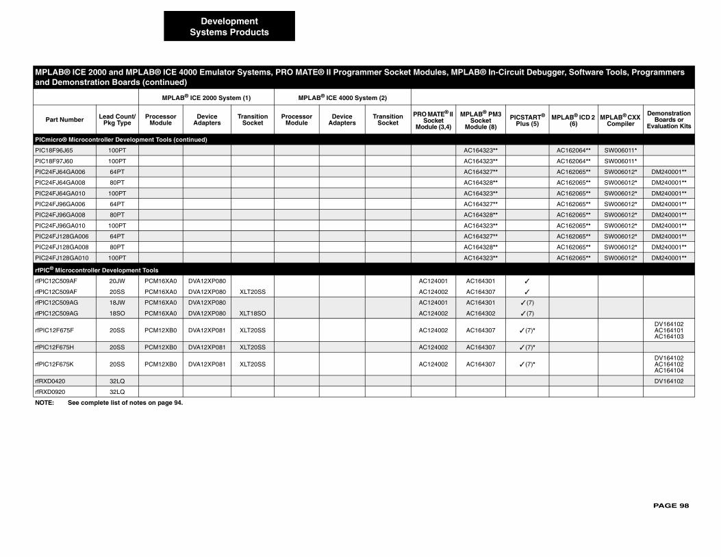
PAGE 98
PICmicr
PIC18F9 AC162064** SW006011*
PIC18F9 AC162064** SW006011*
PIC24FJ AC162065** SW006012* DM240001**
PIC24FJ AC162065** SW006012* DM240001**
PIC24FJ AC162065** SW006012* DM240001**
PIC24FJ AC162065** SW006012* DM240001**
PIC24FJ AC162065** SW006012* DM240001**
PIC24FJ AC162065** SW006012* DM240001**
PIC24FJ AC162065** SW006012* DM240001**
PIC24FJ AC162065** SW006012* DM240001**
PIC24FJ AC162065** SW006012* DM240001**
rfPIC® M
rfPIC12C ✓
rfPIC12C ✓
rfPIC12C ✓ (7)
rfPIC12C ✓ (7)
rfPIC12F ✓ (7)*DV164102AC164101AC164103
rfPIC12F ✓ (7)*
rfPIC12F ✓ (7)*DV164102AC164102AC164104
rfRXD04 DV164102
rfRXD09
MPLA ircuit Debugger, Software Tools, Programmers and D
Part PICSTART® Plus (5)
MPLAB® ICD 2 (6)
MPLAB® CXX Compiler
Demonstration Boards or
Evaluation Kits
NOTE:
DevelopmentSystems Products
o® Microcontroller Development Tools (continued)
6J65 100PT AC164323**
7J60 100PT AC164323**
64GA006 64PT AC164327**
64GA008 80PT AC164328**
64GA010 100PT AC164323**
96GA006 64PT AC164327**
96GA008 80PT AC164328**
96GA010 100PT AC164323**
128GA006 64PT AC164327**
128GA008 80PT AC164328**
128GA010 100PT AC164323**
icrocontroller Development Tools
509AF 20JW PCM16XA0 DVA12XP080 AC124001 AC164301
509AF 20SS PCM16XA0 DVA12XP080 XLT20SS AC124002 AC164307
509AG 18JW PCM16XA0 DVA12XP080 AC124001 AC164301
509AG 18SO PCM16XA0 DVA12XP080 XLT18SO AC124002 AC164302
675F 20SS PCM12XB0 DVA12XP081 XLT20SS AC124002 AC164307
675H 20SS PCM12XB0 DVA12XP081 XLT20SS AC124002 AC164307
675K 20SS PCM12XB0 DVA12XP081 XLT20SS AC124002 AC164307
20 32LQ
20 32LQ
B® ICE 2000 and MPLAB® ICE 4000 Emulator Systems, PRO MATE® II Programmer Socket Modules, MPLAB® In-Cemonstration Boards (continued)
MPLAB® ICE 2000 System (1) MPLAB® ICE 4000 System (2)
Number Lead Count/Pkg Type
Processor Module
Device Adapters
Transition Socket
Processor Module
Device Adapters
Transition Socket
PRO MATE® II Socket
Module (3,4)
MPLAB® PM3Socket
Module (8)
See complete list of notes on page 94.

PAGE 99
dsPIC®
dsPIC30 ✓ SW006012 DM300017
dsPIC30 ✓ SW006012 DM300017 DM300018
dsPIC30 ✓ SW006012
dsPIC30 ✓ * SW006012
dsPIC30 ✓ * SW006012 DM300018
dsPIC30 ✓ * SW006012
dsPIC30 ✓ * SW006012 DM300017
dsPIC30 ✓ * SW006012 DM300017, DM300018
dsPIC30 ✓ * SW006012
dsPIC30 ✓ SW006012 DM300017
dsPIC30 ✓ SW006012 DM300017, DM300018
dsPIC30 ✓ SW006012
dsPIC30 ✓ SW006012 DM30018
dsPIC30 ✓ SW006012
dsPIC30 ✓ SW006012
dsPIC30 ✓ SW006012
dsPIC30 ✓ SW006012 DM300018
dsPIC30 ✓ SW006012
dsPIC30 ✓ SW006012 DM300017
dsPIC30 ✓ SW006012 DM300017, DM300018*
dsPIC30 ✓ SW006012
dsPIC30 ✓ SW006012 DM300018
dsPIC30 ✓ SW006012
dsPIC30 ✓ SW006012
dsPIC30 ✓ SW006012 DM300018
dsPIC30 ✓ SW006012
dsPIC30 ✓ SW006012
MPLA ircuit Debugger, Software Tools, Programmers and D
Part PICSTART® Plus (5)
MPLAB® ICD 2 (6)
MPLAB® CXX Compiler
Demonstration Boards or
Evaluation Kits
NOTE:
DevelopmentSystems Products
DSC Development Tools
F2010 28SO PMF30XA1 DAF30-4 XLT28SO AC30F004 AC164302
F2010 28SP PMF30XA1 DAF30-4 ACICE0204 AC30F004 AC164301
F2010 28MM PMF30XA1 DAF30-4 XLT28QFN4 AC164322
F2011 18SO PMF30XA1 DAF30-4 XLT18SO AC30F005 AC164302
F2011 18P PMF30XA1 DAF30-4 ACICE0202 AC30F005 AC164301
F2011 28ML PMF30XA1 DAF30-4 AC164322
F2012 28SO PMF30XA1 DAF30-4 XLT28SO AC30F004 AC164302
F2012 28SP PMF30XA1 DAF30-4 ACICE0204 AC30F004 AC164301
F2012 28ML PMF30XA1 DAF30-4 XLT28QFN4 AC164322
F3010 28SO PMF30XA1 DAF30-4 XLT28SO AC30F004 AC164302
F3010 28SP PMF30XA1 DAF30-4 ACICE0204 AC30F004 AC164301
F3010 44ML PMF30XA1 DAF30-4 XLT44QFN4 AC164322
F3011 40P PMF30XA1 DAF30-4 ACICE0206 AC30F003 AC164301
F3011 44PT PMF30XA1 DAF30-3 XLT44PT or XLT44PT3 AC30F006 AC164305
F3011 44ML PMF30XA1 DAF30-4 XLT44QFN2 AC164322
F3012 18SO PMF30XA1 DAF30-4 XLT18SO AC164302
F3012 18P PMF30XA1 DAF30-4 ACICE0202 AC164301
F3012 44ML PMF30XA1 DAF30-4 XLT44QFN5* AC164322
F3013 28SO PMF30XA1 DAF30-4 XLT28SO AC30F004 AC164302
F3013 28SP PMF30XA1 DAF30-4 ACICE0204 AC30F004 AC164301
F3013 44ML PMF30XA1 DAF30-4 XLT44QFN3* AC164322
F3014 40P PMF30XA1 DAF30-4 ACICE0206 AC30F003 AC164301
F3014 44PT PMF30XA1 DAF30-3 XLT44PT or XLT44PT3 AC30F006 AC164305
F3014 44ML PMF30XA1 DAF30-4 XLT44QFN2 AC164322
F4011 40P PMF30XA1 DAF30-4 ACICE0206 AC30F003 AC164301
F4011 44PT PMF30XA1 DAF30-3 XLT44PT or XLT44PT3 AC30F006 AC164305
F4011 44ML PMF30XA1 DAF30-4 XLT44QFN2 AC164322
B® ICE 2000 and MPLAB® ICE 4000 Emulator Systems, PRO MATE® II Programmer Socket Modules, MPLAB® In-Cemonstration Boards (continued)
MPLAB® ICE 2000 System (1) MPLAB® ICE 4000 System (2)
Number Lead Count/Pkg Type
Processor Module
Device Adapters
Transition Socket
Processor Module
Device Adapters
Transition Socket
PRO MATE® II Socket
Module (3,4)
MPLAB® PM3Socket
Module (8)
See complete list of notes on page 94.
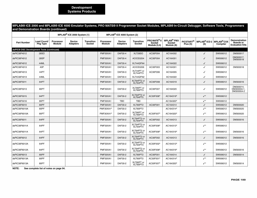
PAGE 100
dsPIC®
dsPIC30 ✓ SW006012 DM300017
dsPIC30 ✓ SW006012 DM300017, DM300018
dsPIC30 ✓ SW006012
dsPIC30 ✓ SW006012 DM300018
dsPIC30 ✓ SW006012
dsPIC30 ✓ SW006012
dsPIC30 ✓ SW006012 DM300016
dsPIC30 ✓ SW006012DM300014,
DM300004-1,DM300004-2
dsPIC30 ✓ * SW006012
dsPIC30 ✓ * SW006012
dsPIC30 ✓ SW006012 DM300020
dsPIC30 ✓ * SW006012 DM300020
dsPIC30 ✓ * SW006012 DM300020
dsPIC30 ✓ SW006012 DM300016
dsPIC30 ✓ * SW006012
dsPIC30 ✓ * SW006012 DM300016
dsPIC30 ✓ SW006012 DM300016
dsPIC30 ✓ * SW006012
dsPIC30 ✓ * SW006012 DM300016
dsPIC30 ✓ SW006012 DM300014
dsPIC30 ✓ * SW006012
dsPIC30 ✓ * SW006012 DM300014
MPLA ircuit Debugger, Software Tools, Programmers and D
Part PICSTART® Plus (5)
MPLAB® ICD 2 (6)
MPLAB® CXX Compiler
Demonstration Boards or
Evaluation Kits
NOTE:
DevelopmentSystems Products
DSC Development Tools (continued)
F4012 28SO PMF30XA1 DAF30-4 XLT28SO AC30F004 AC164302
F4012 28SP PMF30XA1 DAF30-4 ACICE0204 AC30F004 AC164301
F4012 44ML PMF30XA1 DAF30-4 XLT44QFN4 AC164322
F4013 40P PMF30XA1 DAF30-4 ACICE0206 AC30F003 AC164301
F4013 44PT PMF30XA1 DAF30-3 XLT44PT or XLT44PT3 AC30F006 AC164305
F4013 44ML PMF30XA1 DAF30-4 XLT44QFN2 AC164322
F5011 64PT PMF30XA1 DAF30-2 XLT64PT2 or XLT64PT5 AC30F008 AC164319
F5013 80PT PMF30XA1 DAF30-2 XLT80PT or XLT80PT3 AC30F007 AC164320
F5015 64PT PMF30XA1 DAF30-2 XLT64PT2 or XLT64PT5 AC30F008* AC164319*
F5016 80PT PMF30XA1 TBD TBD AC164320*
F6010 80PF PMF30XA1 DAF30-2 XLT80PT2 AC30F001 AC164314
F6010A 80PF PMF30XA1* DAF30-2 XLT80PT2 AC164314*
F6010A 80PT PMF30XA1* DAF30-2 XLT80PT or XLT80PT3 AC30F007* AC164320*
F6011 64PF PMF30XA1 DAF30-2 XLT64PT3 or XLT64PT4 AC30F002 AC164313
F6011A 64PF PMF30XA1 DAF30-2 XLT64PT3 or XLT64PT4 AC30F008* AC164313*
F6011A 64PT PMF30XA1 DAF30-2 XLT64PT2 or XLT64PT5 AC30F008* AC164319*
F6012 64PF PMF30XA1 DAF30-2 XLT64PT3 or XLT64PT4 AC30F002 AC164313
F6012A 64PF PMF30XA1 DAF30-2 XLT64PT3 or XLT64PT4 AC30F002* AC164313*
F6012A 64PT PMF30XA1 DAF30-2 XLT64PT2 or XLT64PT5 AC30F008* AC164319*
F6013 80PF PMF30XA1 DAF30-2 XLT80PT2 AC30F001 AC164314
F6013A 80PF PMF30XA1 DAF30-2 XLT80PT2 AC30F001* AC164314*
F6013A 80PT PMF30XA1 DAF30-2 XLT80PT or XLT80PT3 AC30F007* AC164320*
B® ICE 2000 and MPLAB® ICE 4000 Emulator Systems, PRO MATE® II Programmer Socket Modules, MPLAB® In-Cemonstration Boards (continued)
MPLAB® ICE 2000 System (1) MPLAB® ICE 4000 System (2)
Number Lead Count/Pkg Type
Processor Module
Device Adapters
Transition Socket
Processor Module
Device Adapters
Transition Socket
PRO MATE® II Socket
Module (3,4)
MPLAB® PM3Socket
Module (8)
See complete list of notes on page 94.
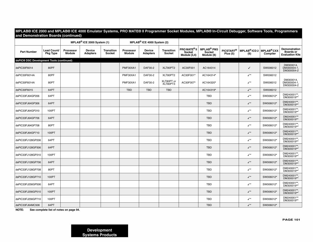
PAGE 101
dsPIC®
dsPIC30 ✓ SW006012DM300014,
DM300004-1,DM300004-2
dsPIC30 ✓ * SW006012
dsPIC30 ✓ * SW006012DM300014,
DM300004-1, DM300004-2
dsPIC30 ✓ * SW006012
dsPIC33 ✓ * SW006012* DM240001**, DM300019**
dsPIC33 ✓ * SW006012* DM240001**, DM300019**
dsPIC33 ✓ * SW006012* DM240001**, DM300019**
dsPIC33 ✓ * SW006012* DM240001** DM300019**
dsPIC33 ✓ * SW006012* DM240001**, DM300019**
dsPIC33 ✓ * SW006012* DM240001**, DM300019**
dsPIC33 ✓ * SW006012* DM240001**, DM300019**
dsPIC33 ✓ * SW006012* DM240001**, DM300019**
dsPIC33 ✓ * SW006012* DM240001**, DM300019**
dsPIC33 ✓ * SW006012* DM240001**, DM300019**
dsPIC33 ✓ * SW006012* DM240001**, DM300019**
dsPIC33 ✓ * SW006012* DM240001**, DM300019**
dsPIC33 ✓ * SW006012* DM240001**, DM300019**
dsPIC33 ✓ * SW006012* DM240001**, DM300019**
dsPIC33 ✓ * SW006012* DM240001** DM300019**
dsPIC33 ✓ * SW006012*
MPLA ircuit Debugger, Software Tools, Programmers and D
Part PICSTART® Plus (5)
MPLAB® ICD 2 (6)
MPLAB® CXX Compiler
Demonstration Boards or
Evaluation Kits
NOTE:
DevelopmentSystems Products
DSC Development Tools (continued)
F6014 80PF PMF30XA1 DAF30-2 XLT80PT2 AC30F001 AC164314
F6014A 80PF PMF30XA1 DAF30-2 XLT80PT2 AC30F001* AC164314*
F6014A 80PT PMF30XA1 DAF30-2 XLT80PT or XLT80PT3 AC30F007* AC164320*
F6015 64PT TBD TBD TBD AC164319*
FJ64GP206 64PT TBD
FJ64GP306 64PT TBD
FJ64GP310 100PT TBD
FJ64GP706 64PT TBD
FJ64GP708 80PT TBD
FJ64GP710 100PT TBD
FJ128GP206 64PT TBD
FJ128GP306 64PT TBD
FJ128GP310 100PT TBD
FJ128GP706 64PT TBD
FJ128GP708 80PT TBD
FJ128GP710 100PT TBD
FJ256GP506 64PT TBD
FJ256GP510 100PT TBD
FJ256GP710 100PT TBD
FJ64MC506 64PT TBD
B® ICE 2000 and MPLAB® ICE 4000 Emulator Systems, PRO MATE® II Programmer Socket Modules, MPLAB® In-Cemonstration Boards (continued)
MPLAB® ICE 2000 System (1) MPLAB® ICE 4000 System (2)
Number Lead Count/Pkg Type
Processor Module
Device Adapters
Transition Socket
Processor Module
Device Adapters
Transition Socket
PRO MATE® II Socket
Module (3,4)
MPLAB® PM3Socket
Module (8)
See complete list of notes on page 94.
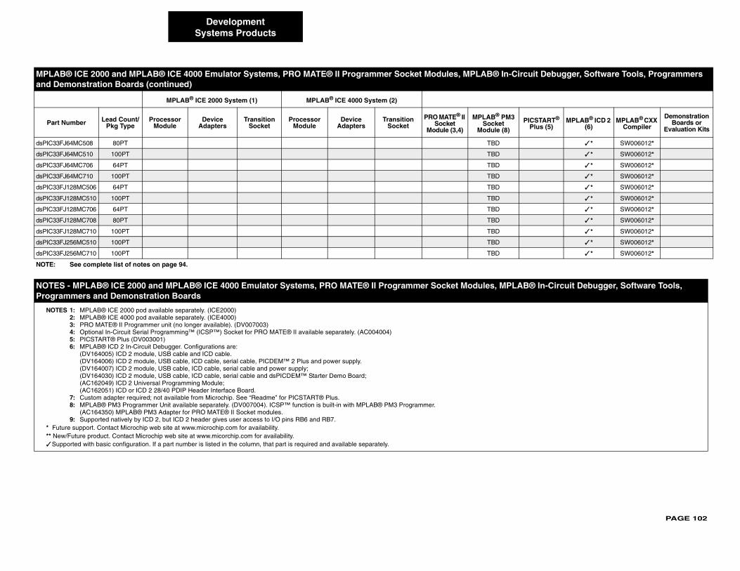
PAGE 102
dsPIC33 ✓ * SW006012*
dsPIC33 ✓ * SW006012*
dsPIC33 ✓ * SW006012*
dsPIC33 ✓ * SW006012*
dsPIC33 ✓ * SW006012*
dsPIC33 ✓ * SW006012*
dsPIC33 ✓ * SW006012*
dsPIC33 ✓ * SW006012*
dsPIC33 ✓ * SW006012*
dsPIC33 ✓ * SW006012*
dsPIC33 ✓ * SW006012*
NOTE AB® In-Circuit Debugger, Software Tools, Progra
NOTE
* Fu** Ne✓ Su
MPLA ircuit Debugger, Software Tools, Programmers and D
Part PICSTART® Plus (5)
MPLAB® ICD 2 (6)
MPLAB® CXX Compiler
Demonstration Boards or
Evaluation Kits
NOTE:
DevelopmentSystems Products
FJ64MC508 80PT TBD
FJ64MC510 100PT TBD
FJ64MC706 64PT TBD
FJ64MC710 100PT TBD
FJ128MC506 64PT TBD
FJ128MC510 100PT TBD
FJ128MC706 64PT TBD
FJ128MC708 80PT TBD
FJ128MC710 100PT TBD
FJ256MC510 100PT TBD
FJ256MC710 100PT TBD
S - MPLAB® ICE 2000 and MPLAB® ICE 4000 Emulator Systems, PRO MATE® II Programmer Socket Modules, MPLmmers and Demonstration Boards
S 1: MPLAB® ICE 2000 pod available separately. (ICE2000)2: MPLAB® ICE 4000 pod available separately. (ICE4000)3: PRO MATE® II Programmer unit (no longer available). (DV007003)4: Optional In-Circuit Serial Programming™ (ICSP™) Socket for PRO MATE® II available separately. (AC004004)5: PICSTART® Plus (DV003001)6: MPLAB® ICD 2 In-Circuit Debugger. Configurations are:
(DV164005) ICD 2 module, USB cable and ICD cable.(DV164006) ICD 2 module, USB cable, ICD cable, serial cable, PICDEM™ 2 Plus and power supply.(DV164007) ICD 2 module, USB cable, ICD cable, serial cable and power supply;(DV164030) ICD 2 module, USB cable, ICD cable, serial cable and dsPICDEM™ Starter Demo Board;(AC162049) ICD 2 Universal Programming Module;(AC162051) ICD or ICD 2 28/40 PDIP Header Interface Board.
7: Custom adapter required; not available from Microchip. See “Readme” for PICSTART® Plus.8: MPLAB® PM3 Programmer Unit available separately. (DV007004). ICSP™ function is built-in with MPLAB® PM3 Programmer.
(AC164350) MPLAB® PM3 Adapter for PRO MATE® II Socket modules.9: Supported natively by ICD 2, but ICD 2 header gives user access to I/O pins RB6 and RB7.
ture support. Contact Microchip web site at www.microchip.com for availability.w/Future product. Contact Microchip web site at www.micorchip.com for availability.pported with basic configuration. If a part number is listed in the column, that part is required and available separately.
B® ICE 2000 and MPLAB® ICE 4000 Emulator Systems, PRO MATE® II Programmer Socket Modules, MPLAB® In-Cemonstration Boards (continued)
MPLAB® ICE 2000 System (1) MPLAB® ICE 4000 System (2)
Number Lead Count/Pkg Type
Processor Module
Device Adapters
Transition Socket
Processor Module
Device Adapters
Transition Socket
PRO MATE® II Socket
Module (3,4)
MPLAB® PM3Socket
Module (8)
See complete list of notes on page 94.
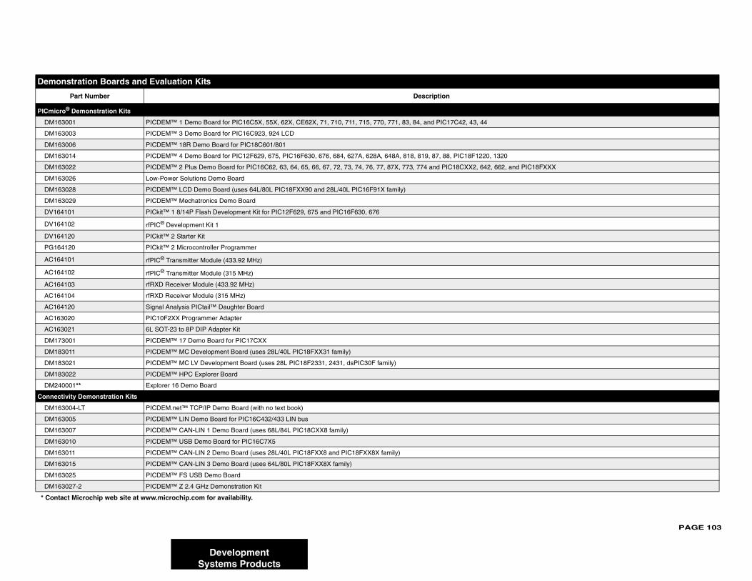
PAGE 103
Demo
PICmicr
DM16
DM16
DM16
DM16
DM16 IC18FXXX
DM16
DM16
DM16
DV16
DV16
DV16
PG16
AC16
AC16
AC16
AC16
AC16
AC16
AC16
DM17
DM18
DM18
DM18
DM24
Connec
DM16
DM16
DM16
DM16
DM16
DM16
DM16
DM16
* Cont
DevelopmentSystems Products
nstration Boards and Evaluation Kits
Part Number Description
o® Demonstration Kits
3001 PICDEM™ 1 Demo Board for PIC16C5X, 55X, 62X, CE62X, 71, 710, 711, 715, 770, 771, 83, 84, and PIC17C42, 43, 44
3003 PICDEM™ 3 Demo Board for PIC16C923, 924 LCD
3006 PICDEM™ 18R Demo Board for PIC18C601/801
3014 PICDEM™ 4 Demo Board for PIC12F629, 675, PIC16F630, 676, 684, 627A, 628A, 648A, 818, 819, 87, 88, PIC18F1220, 1320
3022 PICDEM™ 2 Plus Demo Board for PIC16C62, 63, 64, 65, 66, 67, 72, 73, 74, 76, 77, 87X, 773, 774 and PIC18CXX2, 642, 662, and P
3026 Low-Power Solutions Demo Board
3028 PICDEM™ LCD Demo Board (uses 64L/80L PIC18FXX90 and 28L/40L PIC16F91X family)
3029 PICDEM™ Mechatronics Demo Board
4101 PICkit™ 1 8/14P Flash Development Kit for PIC12F629, 675 and PIC16F630, 676
4102 rfPIC® Development Kit 1
4120 PICkit™ 2 Starter Kit
4120 PICkit™ 2 Microcontroller Programmer
4101 rfPIC® Transmitter Module (433.92 MHz)
4102 rfPIC® Transmitter Module (315 MHz)
4103 rfRXD Receiver Module (433.92 MHz)
4104 rfRXD Receiver Module (315 MHz)
4120 Signal Analysis PICtail™ Daughter Board
3020 PIC10F2XX Programmer Adapter
3021 6L SOT-23 to 8P DIP Adapter Kit
3001 PICDEM™ 17 Demo Board for PIC17CXX
3011 PICDEM™ MC Development Board (uses 28L/40L PIC18FXX31 family)
3021 PICDEM™ MC LV Development Board (uses 28L PIC18F2331, 2431, dsPIC30F family)
3022 PICDEM™ HPC Explorer Board
0001** Explorer 16 Demo Board
tivity Demonstration Kits
3004-LT PICDEM.net™ TCP/IP Demo Board (with no text book)
3005 PICDEM™ LIN Demo Board for PIC16C432/433 LIN bus
3007 PICDEM™ CAN-LIN 1 Demo Board (uses 68L/84L PIC18CXX8 family)
3010 PICDEM™ USB Demo Board for PIC16C7X5
3011 PICDEM™ CAN-LIN 2 Demo Board (uses 28L/40L PIC18FXX8 and PIC18FXX8X family)
3015 PICDEM™ CAN-LIN 3 Demo Board (uses 64L/80L PIC18FXX8X family)
3025 PICDEM™ FS USB Demo Board
3027-2 PICDEM™ Z 2.4 GHz Demonstration Kit
act Microchip web site at www.microchip.com for availability.
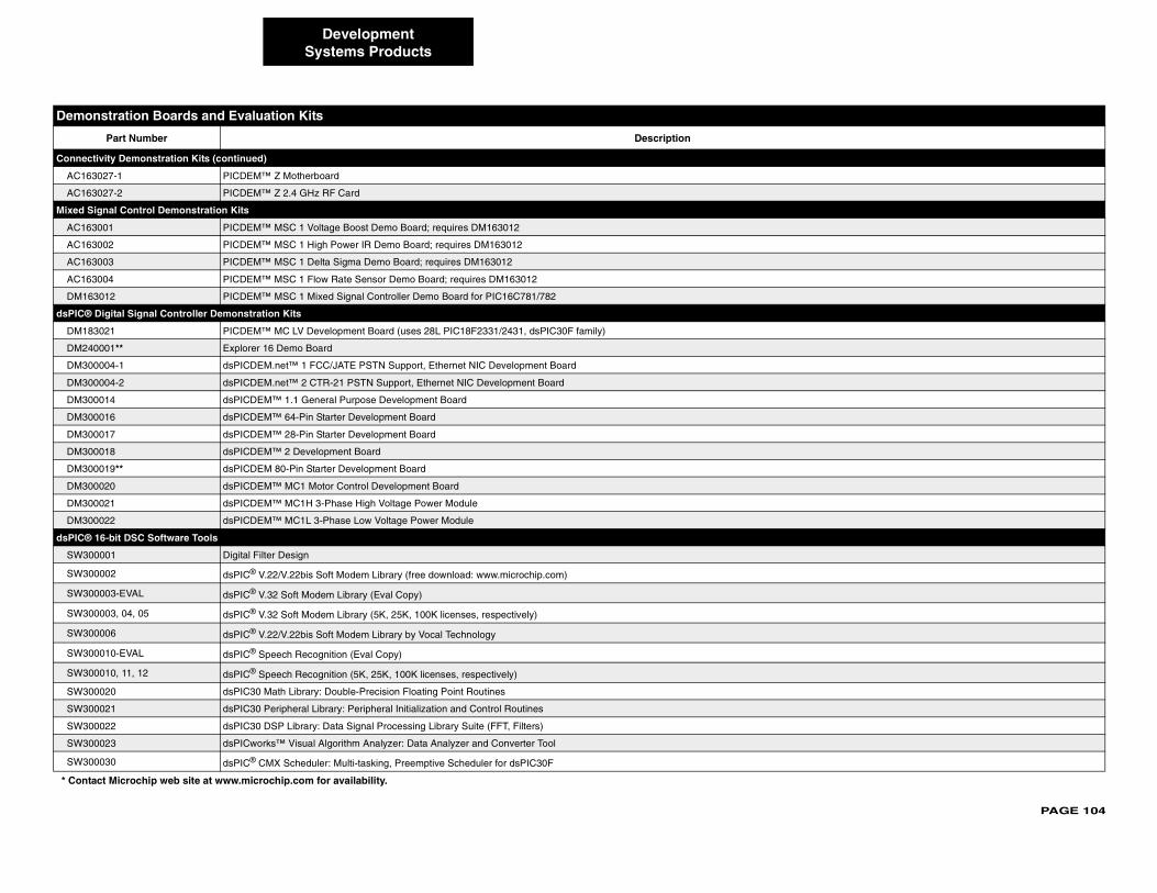
PAGE 104
Connec
AC163
AC163
Mixed S
AC163
AC163
AC163
AC163
DM16
dsPIC®
DM18
DM24
DM30
DM30
DM30
DM30
DM30
DM30
DM30
DM30
DM30
DM30
dsPIC®
SW30
SW30
SW30
SW30
SW30
SW30
SW30
SW30
SW30
SW30
SW30
SW30
Demo
* Conta
DevelopmentSystems Products
tivity Demonstration Kits (continued)
027-1 PICDEM™ Z Motherboard
027-2 PICDEM™ Z 2.4 GHz RF Card
ignal Control Demonstration Kits
001 PICDEM™ MSC 1 Voltage Boost Demo Board; requires DM163012
002 PICDEM™ MSC 1 High Power IR Demo Board; requires DM163012
003 PICDEM™ MSC 1 Delta Sigma Demo Board; requires DM163012
004 PICDEM™ MSC 1 Flow Rate Sensor Demo Board; requires DM163012
3012 PICDEM™ MSC 1 Mixed Signal Controller Demo Board for PIC16C781/782
Digital Signal Controller Demonstration Kits
3021 PICDEM™ MC LV Development Board (uses 28L PIC18F2331/2431, dsPIC30F family)
0001** Explorer 16 Demo Board
0004-1 dsPICDEM.net™ 1 FCC/JATE PSTN Support, Ethernet NIC Development Board
0004-2 dsPICDEM.net™ 2 CTR-21 PSTN Support, Ethernet NIC Development Board
0014 dsPICDEM™ 1.1 General Purpose Development Board
0016 dsPICDEM™ 64-Pin Starter Development Board
0017 dsPICDEM™ 28-Pin Starter Development Board
0018 dsPICDEM™ 2 Development Board
0019** dsPICDEM 80-Pin Starter Development Board
0020 dsPICDEM™ MC1 Motor Control Development Board
0021 dsPICDEM™ MC1H 3-Phase High Voltage Power Module
0022 dsPICDEM™ MC1L 3-Phase Low Voltage Power Module
16-bit DSC Software Tools
0001 Digital Filter Design
0002 dsPIC® V.22/V.22bis Soft Modem Library (free download: www.microchip.com)
0003-EVAL dsPIC® V.32 Soft Modem Library (Eval Copy)
0003, 04, 05 dsPIC® V.32 Soft Modem Library (5K, 25K, 100K licenses, respectively)
0006 dsPIC® V.22/V.22bis Soft Modem Library by Vocal Technology
0010-EVAL dsPIC® Speech Recognition (Eval Copy)
0010, 11, 12 dsPIC® Speech Recognition (5K, 25K, 100K licenses, respectively)
0020 dsPIC30 Math Library: Double-Precision Floating Point Routines
0021 dsPIC30 Peripheral Library: Peripheral Initialization and Control Routines
0022 dsPIC30 DSP Library: Data Signal Processing Library Suite (FFT, Filters)
0023 dsPICworks™ Visual Algorithm Analyzer: Data Analyzer and Converter Tool
0030 dsPIC® CMX Scheduler: Multi-tasking, Preemptive Scheduler for dsPIC30F
nstration Boards and Evaluation Kits
Part Number Description
ct Microchip web site at www.microchip.com for availability.
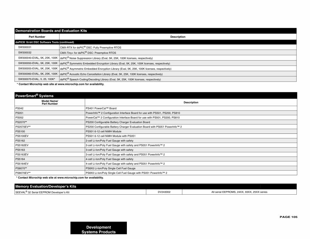
PAGE 105
dsPIC®
SW30
SW30
SW30
SW30
SW30
SW30
SW30
Power
PS042
PS051
PS052
PS2070
PS2070
PS5100
PS5100
PS5162
PS5162
PS5163
PS5163
PS5164
PS5164
PS8070
PS8070
* Conta
Memo
SEEVAL serial EEPROMS, 24XX, 93XX, 25XX series
Demo
* Cont
DevelopmentSystems Products
16-bit DSC Software Tools (continued)
0031 CMX-RTX for dsPIC® DSC: Fully Preemptive RTOS
0032 CMX-Tiny+ for dsPIC® DSC: Preemptive RTOS
0040-EVAL, 5K, 25K, 100K dsPIC® Noise Suppression Library (Eval, 5K, 25K, 100K licenses, respectively)
0050-EVAL, 5K, 25K, 100K dsPIC® Symmetric Embedded Encryption Library (Eval, 5K, 25K, 100K licenses, respectively)
0055-EVAL, 5K, 25K, 100K dsPIC® Asymmetric Embedded Encryption Library (Eval, 5K, 25K, 100K licenses, respectively)
0060-EVAL, 5K, 25K, 100K dsPIC® Acoustic Echo Cancellation Library (Eval, 5K, 25K, 100K licenses, respectively)
0070-EVAL, 5, 25, 100K* dsPIC® Speech Coding/Decoding Library (Eval, 5K, 25K, 100K licenses, respectively)
Smart® SystemsModel Name/Part Number Description
PS401 PowerCal™ Board
PowerInfo™ 2 Configuration Interface Board for use with PS501, PS200, PS810
PowerCal™ 2 Configuration Interface Board for use with PS501, PS200, PS810
** PS200 Configurable Battery Charger Evaluation Board
EV** PS200 Configurable Battery Charger Evaluation Board with PS051 PowerInfo™ 2
PS501 6-12 cell NiMH Module
EV PS501 6-12 cell NiMH Module with PS051
2-cell Li-Ion/Poly Fuel Gauge with safety
EV 2-cell Li-Ion/Poly Fuel Gauge with safety and PS051 PowerInfo™ 2
3-cell Li-Ion/Poly Fuel Gauge with safety
EV 3-cell Li-Ion/Poly Fuel Gauge with safety and PS051 PowerInfo™ 2
4-cell Li-Ion/Poly Fuel Gauge with safety
EV 4-cell Li-Ion/Poly Fuel Gauge with safety and PS051 PowerInfo™ 2
** PS8X0 Li-Ion/Poly Single Cell Fuel Gauge
EV** PS8X0 Li-Ion/Poly Single Cell Fuel Gauge with PS051 PowerInfo™ 2
ct Microchip web site at www.microchip.com for availability.
ry Evaluation/Developer’s Kits® 32 Serial EEPROM Developer’s Kit DV243002 All
nstration Boards and Evaluation Kits
Part Number Description
act Microchip web site at www.microchip.com for availability.

PAGE 106
KEELO
HCS410/412 HCS473 HCS500/515 HCS512
KEELOQ® DM303005 – –
KEELOQ® DM303006 DM303006 DM303006
PRO MA AC004002 AC004003 – AC164002
PRO MA AC004001 AC004007 – AC164001
PRO MA AC004004 AC004004 AC004004
* Suppo
RFID E
F355 MCRF450/452
13.56 M , DV103006 DV103006
microID® 3003 –
Analo
Interfac Devices Supported
MCP214 MCP2140
MCP215 MCP2150/55
MCP250 P25020, MCP25025, MCP25050, MCP25055
MCP251 MCP2510, MCP2515
MCP212 MCP2120, MCP2150
MCP23X MCP23008, MCP23S08
MCP23X MCP23017, MCP23S17
Linear Devices Supported
MCP6S2 MCP6S22/92
MCP6SX MCP6S22/92
MCP6SX MCP6S22/92
MCP6S2 MCP6S2X
Mixed S Devices Supported
Mixed S CP320X, MCP494X, MCP3221, MCP3201, MCP1525, MCP1541
Evaluatio TX3400X
Single-D CP3001, MCP3002, MCP3201, MCP3202
MCP320 MCP3201/02
MXDEV 01/02, MCP3004,/08, MCP3201/02, MCP3204/08
MCP320 MCP3204, MCP3208
MCP42X MCP42010, MCP42050, MCP42100
MCP402 CP4021, MCP4022, MCP4023, MCP4024
DevelopmentSystems Products
Q® Evaluation KitsHCS101 HCS200/201 HCS300/301/320 HCS360/361 HCS362 HCS365/370
Transponder Evaluation Kit* – – – – – –
Evaluation Kit II* DM303006 DM303006 DM303006 DM303006 DM303006 DM303006
TE® II Universal Programmer for SOIC* AC004002 AC004002 AC004002 AC004002 AC004002 AC004003
TE® II Universal Programmer for DIP* AC004001 AC004001 AC004001 AC004001 AC004001 AC004007
TE® II Universal Programmer for ICSP™* AC004004 AC004004 AC004004 AC004004 AC004004 AC004004
rt is limited to PRO MATE® II using MPLAB® IDE release 5.70.
valuation/Developer’s Kits
MCR
Hz Anti-Collision microID® Developer’s Kit DV103003
Programmer Kit only for MCRF355 PG10
g/Interface Demo/Eval/Developer’s Kits
e Part Number
0 IrDA® Wireless Temp. Demo MCP2140DM-TMPSNS
X Data Logger Demo Board MCP215XDM
XX CAN I/O Expanders Developer’s Kit DV250501 MC
0/2515 CAN Developer’s Kit DV251001
0/2150 Developer’s Kit DM163008
08 Evaluation Board MCP23X08EV
17 Evaluation Board MCP23X17EV
Part Number
2 PGA PICtail™ Demo Board MCP6S22DM-PICTL
2 PGA Photodiode PICtail™ Demo Board MCP6SX2DM-PCTLPD
2 PGA Thermistor PICtail™ Demo Board MCP6SX2DM-PCTLTH
X PGA Evaluation Board MCP6S2XEV
ignal Part Number
ignal PICtail™ Demo Board MXSIGDM TX132X, MCP330X, M
n Kit for Sigma-Delta A/D Converter Family TX3400EV
ual A/D DV3201A M
1/02 Evaluation System Daughter Board DV3201A
Analog Evaluation System DVMCPA MCP30
4/08 Evluation System Daughter Board DV3204A
XX Digital Pot Evaluation Kit DV42XXX
X Evaluation Board MCP402XEV M
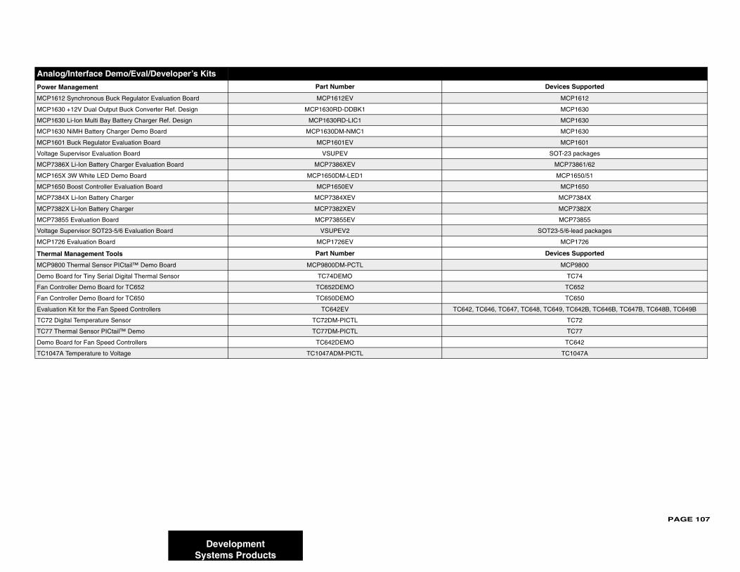
PAGE 107
Power M Devices Supported
MCP161 MCP1612
MCP163 MCP1630
MCP163 MCP1630
MCP163 MCP1630
MCP160 MCP1601
Voltage SOT-23 packages
MCP738 MCP73861/62
MCP165 MCP1650/51
MCP165 MCP1650
MCP738 MCP7384X
MCP738 MCP7382X
MCP738 MCP73855
Voltage SOT23-5/6-lead packages
MCP172 MCP1726
Therma Devices Supported
MCP980 MCP9800
Demo B TC74
Fan Con TC652
Fan Con TC650
Evaluati 7, TC648, TC649, TC642B, TC646B, TC647B, TC648B, TC649B
TC72 Di TC72
TC77 Th TC77
Demo B TC642
TC1047 TC1047A
Analo
DevelopmentSystems Products
anagement Part Number
2 Synchronous Buck Regulator Evaluation Board MCP1612EV
0 +12V Dual Output Buck Converter Ref. Design MCP1630RD-DDBK1
0 Li-Ion Multi Bay Battery Charger Ref. Design MCP1630RD-LIC1
0 NiMH Battery Charger Demo Board MCP1630DM-NMC1
1 Buck Regulator Evaluation Board MCP1601EV
Supervisor Evaluation Board VSUPEV
6X Li-Ion Battery Charger Evaluation Board MCP7386XEV
X 3W White LED Demo Board MCP1650DM-LED1
0 Boost Controller Evaluation Board MCP1650EV
4X Li-Ion Battery Charger MCP7384XEV
2X Li-Ion Battery Charger MCP7382XEV
55 Evaluation Board MCP73855EV
Supervisor SOT23-5/6 Evaluation Board VSUPEV2
6 Evaluation Board MCP1726EV
l Management Tools Part Number
0 Thermal Sensor PICtail™ Demo Board MCP9800DM-PCTL
oard for Tiny Serial Digital Thermal Sensor TC74DEMO
troller Demo Board for TC652 TC652DEMO
troller Demo Board for TC650 TC650DEMO
on Kit for the Fan Speed Controllers TC642EV TC642, TC646, TC64
gital Temperature Sensor TC72DM-PICTL
ermal Sensor PICtail™ Demo TC77DM-PICTL
oard for Fan Speed Controllers TC642DEMO
A Temperature to Voltage TC1047ADM-PICTL
g/Interface Demo/Eval/Developer’s Kits
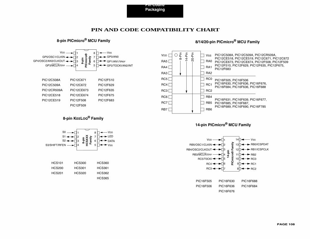
Pin Count/
PAGE 108
T
PIC16F630 PIC16F688
PIC16F636 PIC16F684
PIC16F676
PICmicro® MCU Family
IC12C508A, PIC12C509A, PIC12CR509A,
IC16F630, PIC16F636, PIC16F676,IC16F684, PIC16F636, PIC16F688
IC16F505, PIC16F506
IC16F631, PIC16F639, PIC16F677,IC16F685, PIC16F687,IC16F689, PIC16F690, PIC16F785
IC12CE518, PIC12CE519, PIC12C671, PIC12C672IC12CE673, PIC12CE674, PIC12F508, PIC12F509IC12F510, PIC12F629, PIC12F635, PIC12F675, IC12F683
icro® MCU Family
1
2
3
4
VSS
RB0/ICSPDAT
14
13
12
11
14-p
in
PIC
mic
ro®
Fam
ily
5
6
7
10
9
8
RB1/ICSPCLK
RB2
RC0
RC1
RC2
Packaging
PIN AND CODE COMPATIBILITY CHAR
PIC12C508A PIC12C671 PIC12F510
PIC12C509A PIC12C672 PIC12F629
PIC12CR509A PIC12CE673 PIC12F635
PIC12CE518 PIC12CE674 PIC12F675
PIC12CE519 PIC12F508 PIC12F683
PIC12F509
HCS101 HCS300 HCS360
HCS200 HCS301 HCS361
HCS201 HCS320 HCS362
HCS365
8-pin PICmicro® MCU Family
8
7
6
5
1
2
3
4
8-p
in
PIC
mic
ro®
F
amily
VDD
GP5/OSC1/CLKIN
GP4/OSC2/AN3/CLKOUT
GP3/MCLR/VPP GP2/TOCKI/AN2/INT
GP1/AN1/VREF
GP0/AN0
VSS
8-pin KEELOQ® Family
8
7
6
5
1
2
3
4
8-p
in
HC
SX
XX
F
amily
S0
S1
S2
S3/SHIFT/RFEN VSS
DATA
LED
VDD
PIC16F505
PIC16F506
8/14/20-pin
VDD
RA5
RA4
RA3
RC5
RC4
RC3
RC6
RC7
RB7
VSS
RA0
RA1
RA2
RC0
RC1
RC2
RB4
RB5
RB6
8-P
in
14-P
in
20-P
in P
PP
P
PPP
PPPP
14-pin PICm
VDD
RB5/OSC1/CLKIN
RB4/OSC2/CLKOUT
RB3/MCLR/VPP
RC5/T0CKI
RC4
RC3
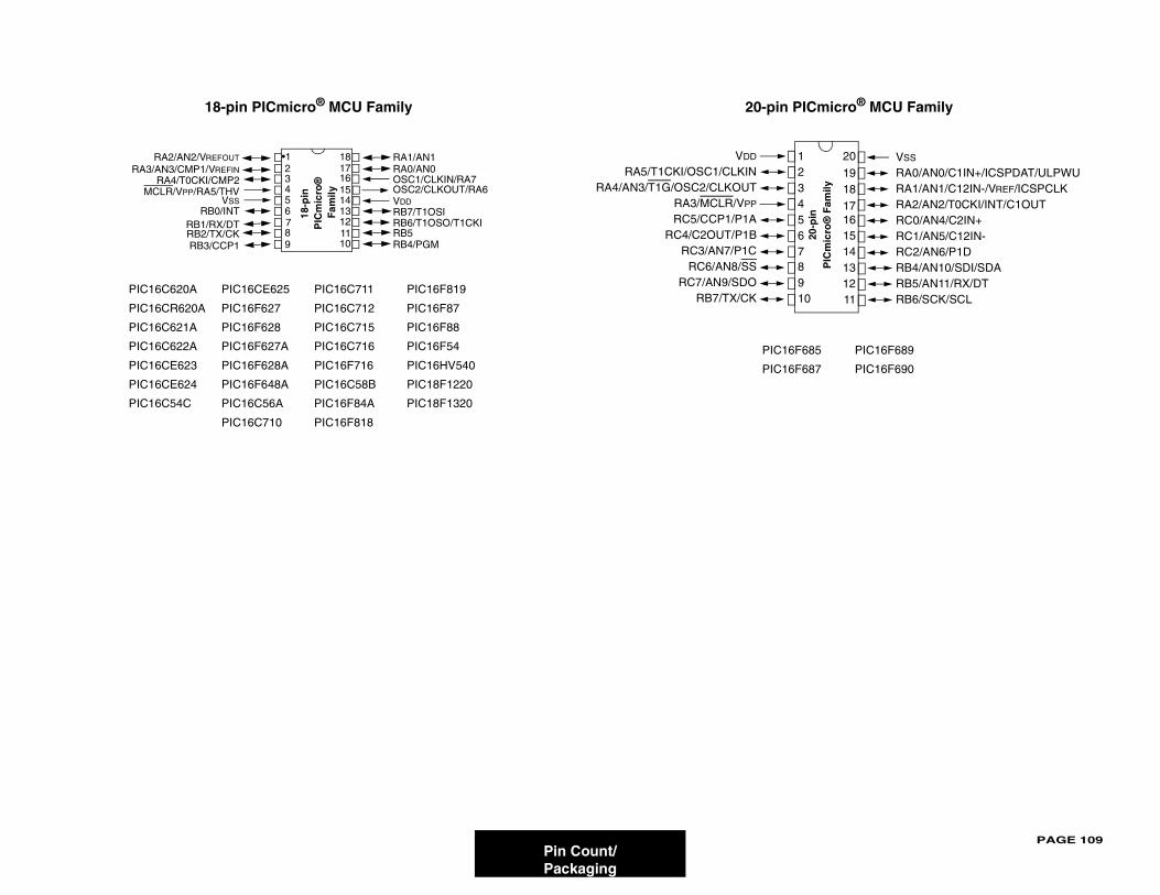
PAGE 109
PIC16F689
PIC16F690
icro® MCU Family
PIC
mic
ro®
Fam
ily
VSS
RA0/AN0/C1IN+/ICSPDAT/ULPWURA1/AN1/C12IN-/VREF/ICSPCLKRA2/AN2/T0CKI/INT/C1OUTRC0/AN4/C2IN+RC1/AN5/C12IN-RC2/AN6/P1DRB4/AN10/SDI/SDARB5/AN11/RX/DTRB6/SCK/SCL
20
191817161514131211
Pin Count/Packaging
PIC16C620A PIC16CE625 PIC16C711 PIC16F819
PIC16CR620A PIC16F627 PIC16C712 PIC16F87
PIC16C621A PIC16F628 PIC16C715 PIC16F88
PIC16C622A PIC16F627A PIC16C716 PIC16F54
PIC16CE623 PIC16F628A PIC16F716 PIC16HV540
PIC16CE624 PIC16F648A PIC16C58B PIC18F1220
PIC16C54C PIC16C56A PIC16F84A PIC18F1320
PIC16C710 PIC16F818
18-pin PICmicro® MCU Family
RA1/AN1RA0/AN0
OSC2/CLKOUT/RA6VDDRB7/T1OSIRB6/T1OSO/T1CKIRB5RB4/PGM
OSC1/CLKIN/RA7
RA2/AN2/VREFOUT
RA3/AN3/CMP1/VREFIN
MCLR/VPP/RA5/THVVSS
RB0/INTRB1/RX/DTRB2/TX/CKRB3/CCP1
RA4/T0CKI/CMP2 2 3 4 5 6 7 8 9
•1 1817
151413121110
16
18-p
in
PIC
mic
ro®
F
amily
PIC16F685
PIC16F687
20-pin PICm
20-p
in
VDD
RA5/T1CKI/OSC1/CLKINRA4/AN3/T1G/OSC2/CLKOUT
RA3/MCLR/VPP
RC5/CCP1/P1ARC4/C2OUT/P1B
RC3/AN7/P1CRC6/AN8/SS
RC7/AN9/SDORB7/TX/CK
12345678910
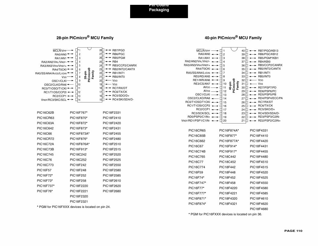
Pin Count/
PAGE 110
IC16F874A* PIC18F4331
IC16F877* PIC18F4410
IC16F877A* PIC18F4420
IC16F914* PIC18F4431
IC16F917* PIC18F4455
IC18C442 PIC18F4480
IC18C452 PIC18F4510
IC18F442 PIC18F4515
IC18F448 PIC18F4520
IC18F452 PIC18F4525
IC18F458 PIC18F4550
IC18F4220 PIC18F4580
IC18F4221 PIC18F4585
IC18F4320 PIC18F4610
IC18F4321 PIC18F4620
PIC18F4680
devices is located on pin 36.
Cmicro® MCU Family
40-p
in
PIC
mic
ro®
F
amily
RB7/PGO/KB13RB6/PGC/KB12RB5/PGM*/KBI1RB4/KBI0RB3/CCP2/CANRXRB2/INT2/CANTX
RB1/INT1RB0/INT0VDD
VSS
RD7/PSP7/PDRD6/PSP6/PCRD5/PSP5/PBRD4/PSP4/ECC/PARC7/RX/DTRC6/TX/CKRC5/SKO/D+RC4/SDI/SDA/D-RD3/PSP3/C2IN-RD2/PSP2/C2IN+
1234567891011121314151617181920
4039383736353433323130292827262524232221
Packaging
PIC16C62B PIC16F767* PIC18F2331
PIC16CR63 PIC16F870* PIC18F2410
PIC16C63A PIC16F872* PIC18F2420
PIC16C642 PIC16F873* PIC18F2431
PIC16C66 PIC16F873A* PIC18F2455
PIC16CR72 PIC16F876* PIC18F2480
PIC16C72A PIC16F876A* PIC18F2510
PIC16C73B PIC16F913* PIC18F2515
PIC16C745 PIC18C242 PIC18F2520
PIC16C76 PIC18C252 PIC18F2525
PIC16C773 PIC18F242 PIC18F2550
PIC16F57 PIC18F248 PIC18F2580
PIC16F72* PIC18F252 PIC18F2585
PIC16F73* PIC18F258 PIC18F2610
PIC16F737* PIC18F2220 PIC18F2620
PIC16F76* PIC18F2221 PIC18F2680
PIC18F2320
PIC18F2321
* PGM for PIC16FXXX devices is located on pin 24.
28-pin PICmicro® MCU Family
1011
23456
1
87
9
121314 15
1617181920
232425
262728
2221
MCLR/VPP
RA0/AN0RA1/AN1
RA2/AN2/VRL/VREF-RA3/AN3/VRH/VREF+
RA4/T0CKIRA5/SS/AN4/AVDD/LVDIN
VSS
OSC1/CLKIOSC2/CLKO/RA6
RC0/T1OSO/T1CKIRC1/T1OS/CCP2I
RC2/CCP1VREF/RC3/SKC/SCL
RB7/PGDRB6/PGCRB5/PGMRB4RB3/CCP2/CANRXRB2/INT2/CANTXRB1/INT1RB0/INT0VDD
VSS
RC7/RX/DTRC6/TX/CKRC5/SDO/D+RC4/SKI/SDA/D-
28-p
in
PIC
mic
ro®
F
amily
PIC16CR65 P
PIC16C65B P
PIC16C662 P
PIC16C67 P
PIC16C74B P
PIC16C765 P
PIC16C77 P
PIC16C774 P
PIC16F59 P
PIC16F74* P
PIC16F747* P
PIC16F77* P
PIC16F777* P
PIC16F871* P
PIC16F874* P
* PGM for PIC16FXXX
40-pin PI
MCLR/VPP
RA0/AN0RA1/AN1
RA2/AN2/VRL/VREF-RA3/AN3/VRH/VREF+
RA4/T0CKI
RA5/SS/AN4/LVDIN
RE0/RD/AN5RE1/WR/AN6RE3/CS/AN7
AVDD
AVSS
OSC1/CLKIOSC2/CLKO/RA6
RC0/T1OSO/T1CKIRC1/T1OSI/CCP2
RC2/CCP1RC3/SCK/SCL
RD0/PSP0/C1IN+VREF/RD1/PSP1/C1IN-
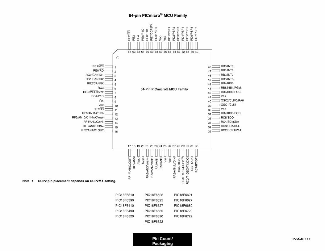
PAGE 111
0
1
2
3
I0
I1/PGM
I2/PGC
LKO/RA6
LKI
I3/PGD
I/SDA
K/SCL
P1/P1A
O
Pin Count/Packaging
PIC18F6310 PIC18F6522 PIC18F6621
PIC18F6390 PIC18F6525 PIC18F6627
PIC18F6410 PIC18F6527 PIC18F6680
PIC18F6490 PIC18F6585 PIC18F6720
PIC18F6520 PIC18F6620 PIC18F6722
PIC18F6622
64-pin PICmicro® MCU Family
1
2
3
4
5
6
7
8
9
10
11
12
13
14
38
37
36
35
34
33
50 49
17 18 19 20 21 22 23 24 25 26
RE
2/C
S
RE
3
RE
4
RE
5/P
1C
RE
6/P
1B
RE
7/C
CP
2(1)
RD
0/P
SP
0
VD
D
VS
S
RD
1/P
SP
1
RD
2/P
SP
2
RD
3/P
SP
3
RD
4/P
SP
4
RD
5/P
SP
5
RD
6/P
SP
6
RD
7/P
SP
7
RE1/WR
RE0/RD
RG0/CANTX1
RG1/CANTX2
RG2/CANRX
RG3
RG5/MCLR/VPP
RG4/P1D
VSS
VDD
RF7/SSRF6/AN11/C1IN-
RF5/AN10/C1IN+/CVREF
RF4/AN9/C2IN-
RF3/AN8/C2IN+
RF2/AN7/C1OUT
RB0/INT
RB1/INT
RB2/INT
RB3/INT
RB4/KB
RB5/KB
RB6/KB
VSS
OSC2/C
OSC1/C
VDD
RB7/KB
RC4/SD
RC3/SC
RC2/CCR
F0/
AN
5
RF
1/A
N6/
C2O
UT
AV
DD
AV
SS
RA
3/A
N3/
VR
EF+
RA
2/A
N2/
VR
EF-
RA
1/A
N1
RA
0/A
N0
VS
S
VD
D
RA
4/T
0CK
I
RA
5/A
N4/
LVD
IN
RC
1/T
1OS
I/CC
P2(1
)
RC
0/T
1OS
O/T
13C
KI
RC
7/R
X/D
T
RC
6/T
X/C
K
RC5/SD
15
16
31
40
39
27 28 29 30 32
48
47
46
45
44
43
42
41
54 53 52 5158 57 56 5560 5964 63 62 61
64-Pin PICmicro® MCU Family
Note 1: CCP2 pin placement depends on CCP2MX setting.
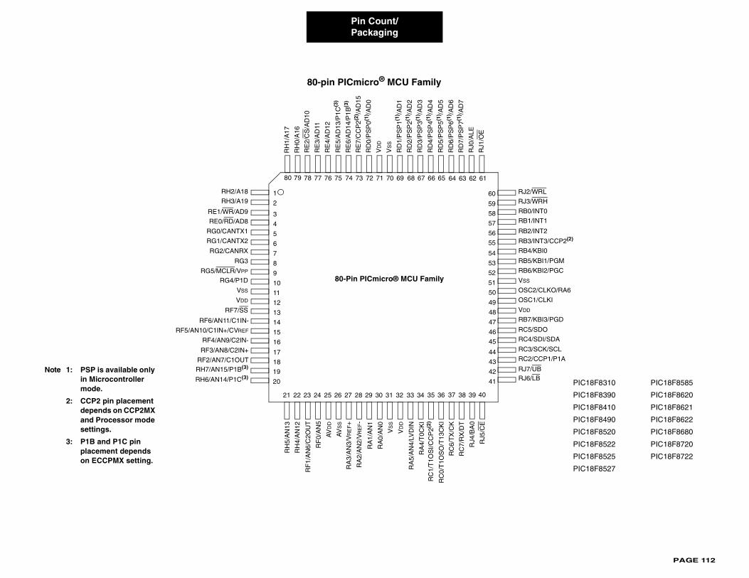
PAGE 112
8F8310 PIC18F8585
8F8390 PIC18F8620
8F8410 PIC18F8621
8F8490 PIC18F8622
8F8520 PIC18F8680
8F8522 PIC18F8720
8F8525 PIC18F8722
8F8527
No
Pin Count/Packaging
80-pin PICmicro® MCU Family
3
4
5
6
7
8
9
10
11
12
13
14
15
16
48
47
46
45
44
43
42
41
4039
64 63 62 61
21 22 23 24 25 26 27 28 29 30 31 32
RE
2/C
S/A
D10
RE
3/A
D11
RE
4/A
D12
RE
5/A
D13
/P1C
(3)
RE
6/A
D14
/P1B
(3)
RE
7/C
CP
2(2) /A
D15
RD
0/P
SP
0(1) /A
D0
VD
D
VS
S
RD
1/P
SP
1(1) /A
D1
RD
2/P
SP
2(1) /A
D2
RD
3/P
SP
3(1) /A
D3
RD
4/P
SP
4(1) /A
D4
RD
5/P
SP
5(1) /A
D5
RD
6/P
SP
6(1) /A
D6
RD
7/P
SP
7(1) /A
D7
RE1/WR/AD9
RE0/RD/AD8
RG0/CANTX1
RG1/CANTX2
RG2/CANRX
RG3
RG5/MCLR/VPP
RG4/P1D
VSS
VDD
RF7/SS
RB0/INT0
RB1/INT1
RB2/INT2
RB3/INT3/CCP2(2)
RB4/KBI0
RB5/KBI1/PGM
RB6/KBI2/PGC
VSS
OSC2/CLKO/RA6
OSC1/CLKI
VDD
RB7/KBI3/PGD
RC4/SDI/SDA
RC3/SCK/SCL
RC2/CCP1/P1A
RF
0/A
N5
RF
1/A
N6/
C2O
UT
AV
DD
AV
SS
RA
3/A
N3/
VR
EF+
RA
2/A
N2/
VR
EF-
RA
1/A
N1
RA
0/A
N0
VS
S
VD
D
RA
4/T
0CK
I
RA
5/A
N4/
LVD
IN
RC
1/T
1OS
I/CC
P2(2
)
RC
0/T
1OS
O/T
13C
KI
RC
7/R
X/D
T
RC
6/T
X/C
K
RC5/SDO
RJ0
/ALE
RJ1
/OE
RH
1/A
17
RH
0/A
16
1
2
RH2/A18
RH3/A19
17
18RH7/AN15/P1B(3)
RH6/AN14/P1C(3)
RH
5/A
N13
RH
4/A
N12
RJ5
/CE
RJ4
/BA
0
37
RJ7/UBRJ6/LB
50
49
RJ2/WRL
RJ3/WRH
19
20
33 34 35 36 38
58
57
56
55
54
53
52
51
60
59
68 67 66 6572 71 70 6974 7378 77 76 757980
RF5/AN10/C1IN+/CVREF
RF4/AN9/C2IN-
RF3/AN8/C2IN+
RF2/AN7/C1OUT
RF6/AN11/C1IN-
80-Pin PICmicro® MCU Family
PIC1
PIC1
PIC1
PIC1
PIC1
PIC1
PIC1
PIC1
te 1: PSP is available only in Microcontroller mode.
2: CCP2 pin placement depends on CCP2MX and Processor mode settings.
3: P1B and P1C pin placement depends on ECCPMX setting.
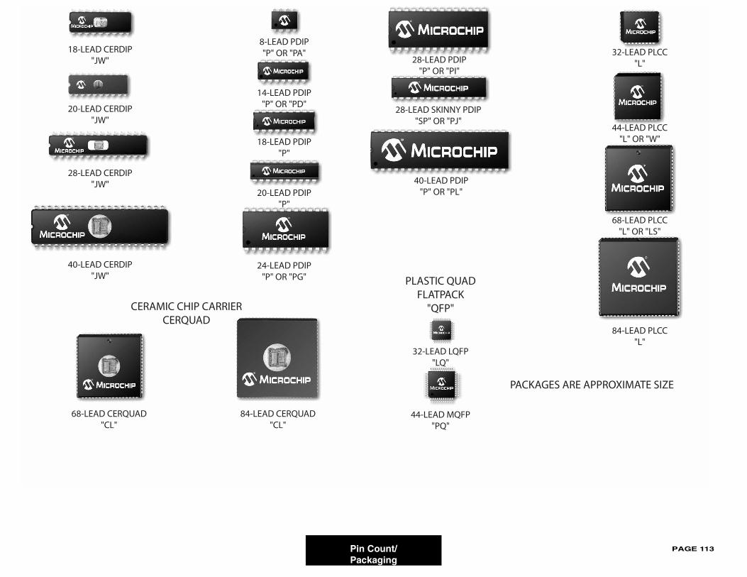
PAGE 113
Pin Count/Packaging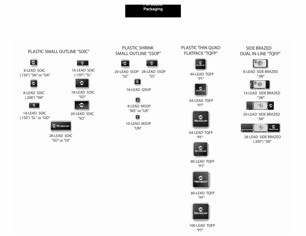
PAGE 114
Pin Count/Packaging
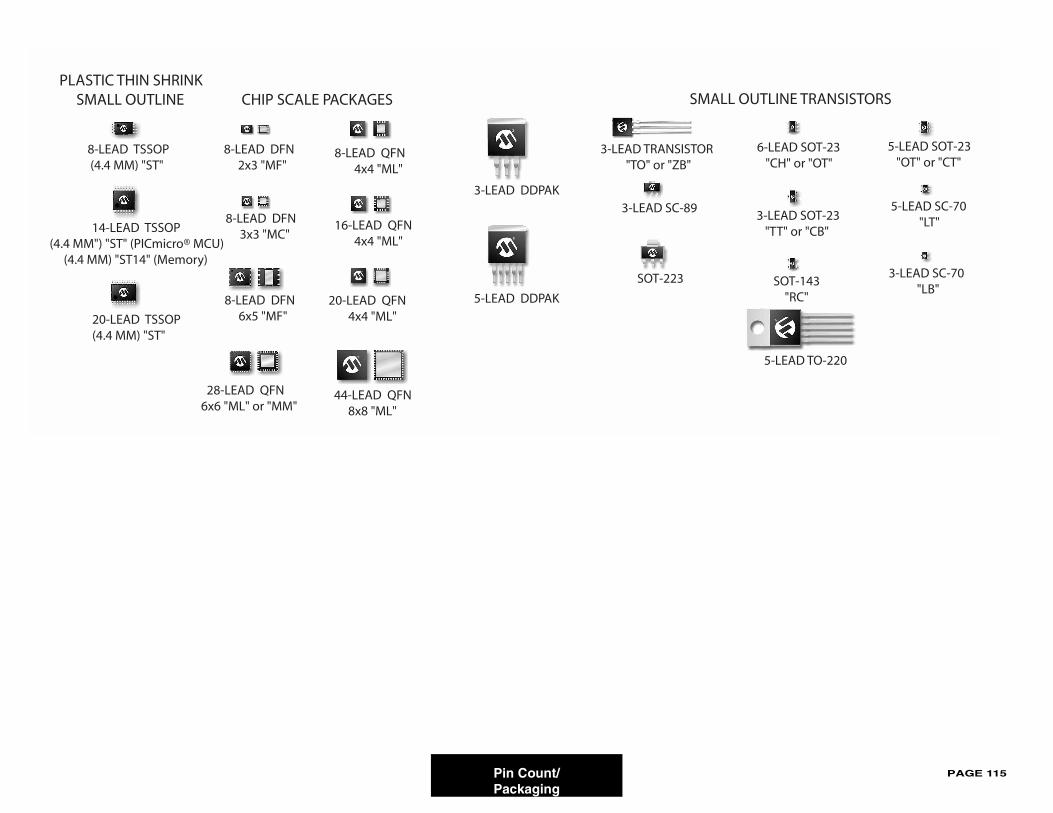
PAGE 115
Pin Count/Packaging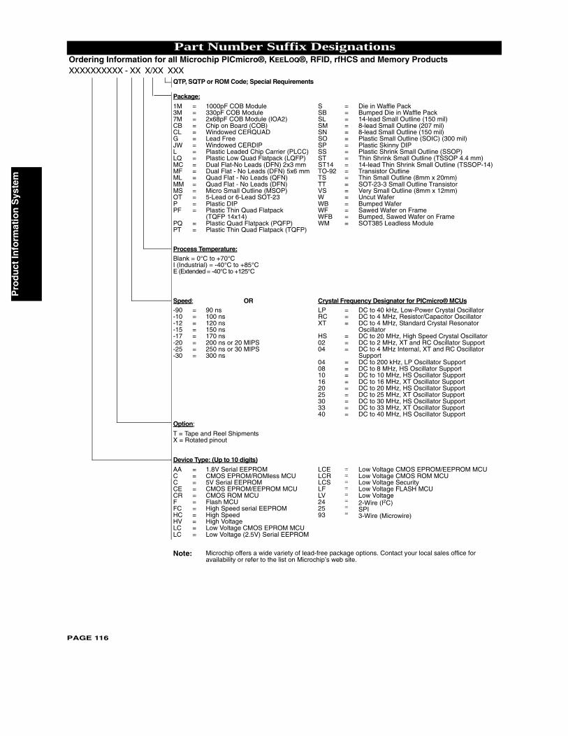
Pro
du
ct In
form
atio
n S
yste
m
Part Number Suffix DesignationsOrdering Information for all Microchip PICmicro®, KEELOQ®, RFID, rfHCS and Memory ProductsXXXXXXXXXX - XX X/XX XXX
QTP, SQTP or ROM Code; Special Requirements
Package:
1M 3M 7MCBCLGJW LLQMCMFML MMMS OT PPF
PQPT
=================
==
1000pF COB Module330pF COB Module2x68pF COB Module (IOA2)Chip on Board (COB)Windowed CERQUADLead FreeWindowed CERDIPPlastic Leaded Chip Carrier (PLCC)Plastic Low Quad Flatpack (LQFP)Dual Flat-No Leads (DFN) 2x3 mmDual Flat - No Leads (DFN) 5x6 mmQuad Flat - No Leads (QFN)Quad Flat - No Leads (DFN)Micro Small Outline (MSOP)5-Lead or 6-Lead SOT-23Plastic DIPPlastic Thin Quad Flatpack (TQFP 14x14)Plastic Quad Flatpack (PQFP)Plastic Thin Quad Flatpack (TQFP)
SSBSL SM SN SO SP SS ST ST14 TO-92 TS TT VS WWB WF WFB WM
===================
Die in Waffle PackBumped Die in Waffle Pack14-lead Small Outline (150 mil)8-lead Small Outline (207 mil)8-lead Small Outline (150 mil)Plastic Small Outline (SOIC) (300 mil)Plastic Skinny DIPPlastic Shrink Small Outline (SSOP)Thin Shrink Small Outline (TSSOP 4.4 mm)14-lead Thin Shrink Small Outline (TSSOP-14)Transistor OutlineThin Small Outline (8mm x 20mm)SOT-23-3 Small Outline TransistorVery Small Outline (8mm x 12mm)Uncut WaferBumped Wafer Sawed Wafer on Frame Bumped, Sawed Wafer on FrameSOT385 Leadless Module
Process Temperature:Blank = 0°C to +70°CI (Industrial) = -40°C to +85°CE (Extended = -40°C to +125°C
Speed: OR Crystal Frequency Designator for PICmicro® MCUs-90 -10 -12 -15 -17 -20 -25 -30
========
90 ns100 ns120 ns150 ns170 ns200 ns or 20 MIPS250 ns or 30 MIPS300 ns
LPRCXT
HS0204
040810162025303340
===
===
=========
DC to 40 kHz, Low-Power Crystal OscillatorDC to 4 MHz, Resistor/Capacitor OscillatorDC to 4 MHz, Standard Crystal Resonator OscillatorDC to 20 MHz, High Speed Crystal OscillatorDC to 2 MHz, XT and RC Oscillator SupportDC to 4 MHz Internal, XT and RC Oscillator SupportDC to 200 kHz, LP Oscillator SupportDC to 8 MHz, HS Oscillator SupportDC to 10 MHz, HS Oscillator SupportDC to 16 MHz, XT Oscillator SupportDC to 20 MHz, HS Oscillator SupportDC to 25 MHz, XT Oscillator SupportDC to 30 MHz, HS Oscillator SupportDC to 33 MHz, XT Oscillator SupportDC to 40 MHz, HS Oscillator Support
Option:
T = Tape and Reel ShipmentsX = Rotated pinout
Device Type: (Up to 10 digits)AA CCCE CR F FCHC HV LC LC
===========
1.8V Serial EEPROMCMOS EPROM/ROMless MCU5V Serial EEPROMCMOS EPROM/EEPROM MCUCMOS ROM MCUFlash MCUHigh Speed serial EEPROMHigh SpeedHigh VoltageLow Voltage CMOS EPROM MCULow Voltage (2.5V) Serial EEPROM
LCE LCR LCS LF LV 24 25 93
========
Low Voltage CMOS EPROM/EEPROM MCULow Voltage CMOS ROM MCULow Voltage SecurityLow Voltage FLASH MCULow Voltage2-Wire (I2C)SPI3-Wire (Microwire)
Note: Microchip offers a wide variety of lead-free package options. Contact your local sales office for
PAGE 116
availability or refer to the list on Microchip’s web site.
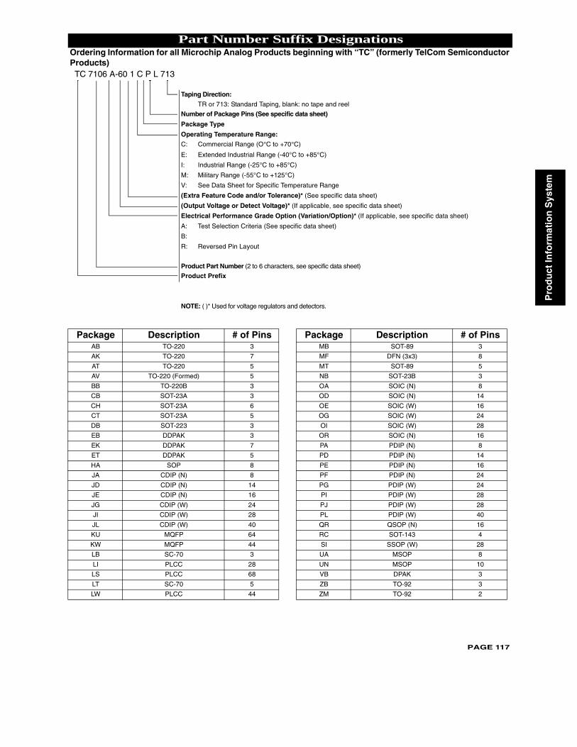
Pro
du
ct In
form
atio
n S
yste
m
PAGE 117
Part Number Suffix DesignationsOrdering Information for all Microchip Analog Products beginning with “TC” (formerly TelCom Semiconductor Products) TC 7106 A-60 1 C P L 713
Taping Direction:
TR or 713: Standard Taping, blank: no tape and reel
Number of Package Pins (See specific data sheet)
Package Type
Operating Temperature Range:
C: Commercial Range (O°C to +70°C)
E: Extended Industrial Range (-40°C to +85°C)
I: Industrial Range (-25°C to +85°C)
M: Military Range (-55°C to +125°C)
V: See Data Sheet for Specific Temperature Range
(Extra Feature Code and/or Tolerance)* (See specific data sheet)
(Output Voltage or Detect Voltage)* (If applicable, see specific data sheet)
Electrical Performance Grade Option (Variation/Option)* (If applicable, see specific data sheet)
A: Test Selection Criteria (See specific data sheet)
B:
R: Reversed Pin Layout
Product Part Number (2 to 6 characters, see specific data sheet)
Product Prefix
NOTE: ( )* Used for voltage regulators and detectors.
Package Description # of Pins Package Description # of PinsAB TO-220 3 MB SOT-89 3
AK TO-220 7 MF DFN (3x3) 8
AT TO-220 5 MT SOT-89 5
AV TO-220 (Formed) 5 NB SOT-23B 3
BB TO-220B 3 OA SOIC (N) 8
CB SOT-23A 3 OD SOIC (N) 14
CH SOT-23A 6 OE SOIC (W) 16
CT SOT-23A 5 OG SOIC (W) 24
DB SOT-223 3 OI SOIC (W) 28
EB DDPAK 3 OR SOIC (N) 16
EK DDPAK 7 PA PDIP (N) 8
ET DDPAK 5 PD PDIP (N) 14
HA SOP 8 PE PDIP (N) 16
JA CDIP (N) 8 PF PDIP (N) 24
JD CDIP (N) 14 PG PDIP (W) 24
JE CDIP (N) 16 PI PDIP (W) 28
JG CDIP (W) 24 PJ PDIP (W) 28
JI CDIP (W) 28 PL PDIP (W) 40
JL CDIP (W) 40 QR QSOP (N) 16
KU MQFP 64 RC SOT-143 4
KW MQFP 44 SI SSOP (W) 28
LB SC-70 3 UA MSOP 8
LI PLCC 28 UN MSOP 10
LS PLCC 68 VB DPAK 3
LT SC-70 5 ZB TO-92 3
LW PLCC 44 ZM TO-92 2
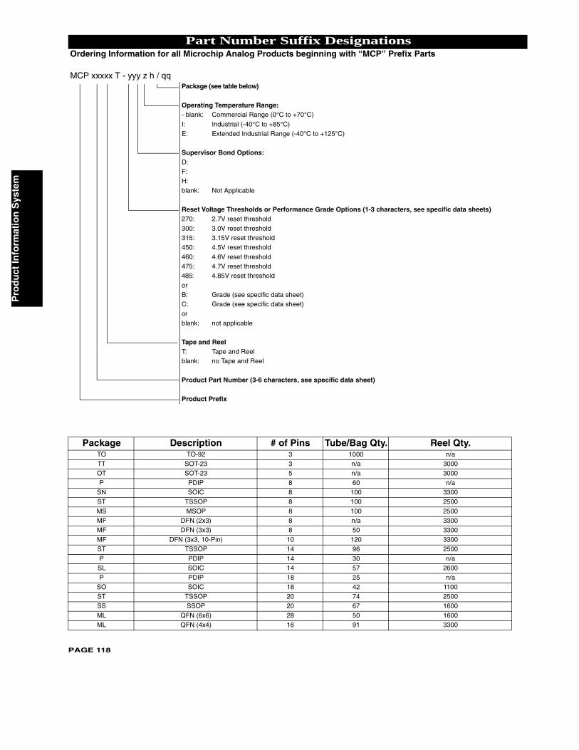
Pro
du
ct In
form
atio
n S
yste
m
PAGE 118
Part Number Suffix DesignationsOrdering Information for all Microchip Analog Products beginning with “MCP” Prefix Parts
MCP xxxxx T - yyy z h / qqPackage (see table below)
Operating Temperature Range:- blank: Commercial Range (0°C to +70°C)
I: Industrial (-40°C to +85°C)E: Extended Industrial Range (-40°C to +125°C)
Supervisor Bond Options:D:F:
H:blank: Not Applicable
Reset Voltage Thresholds or Performance Grade Options (1-3 characters, see specific data sheets)270: 2.7V reset threshold
300: 3.0V reset threshold315: 3.15V reset threshold450: 4.5V reset threshold
460: 4.6V reset threshold475: 4.7V reset threshold485: 4.85V reset threshold
orB: Grade (see specific data sheet)C: Grade (see specific data sheet)
orblank: not applicable
Tape and ReelT: Tape and Reelblank: no Tape and Reel
Product Part Number (3-6 characters, see specific data sheet)
Product Prefix
Package Description # of Pins Tube/Bag Qty. Reel Qty.TO TO-92 3 1000 n/aTT SOT-23 3 n/a 3000OT SOT-23 5 n/a 3000
P PDIP 8 60 n/aSN SOIC 8 100 3300ST TSSOP 8 100 2500
MS MSOP 8 100 2500MF DFN (2x3) 8 n/a 3300MF DFN (3x3) 8 50 3300
MF DFN (3x3, 10-Pin) 10 120 3300ST TSSOP 14 96 2500
P PDIP 14 30 n/aSL SOIC 14 57 2600P PDIP 18 25 n/a
SO SOIC 18 42 1100ST TSSOP 20 74 2500SS SSOP 20 67 1600
ML QFN (6x6) 28 50 1600ML QFN (4x4) 16 91 3300
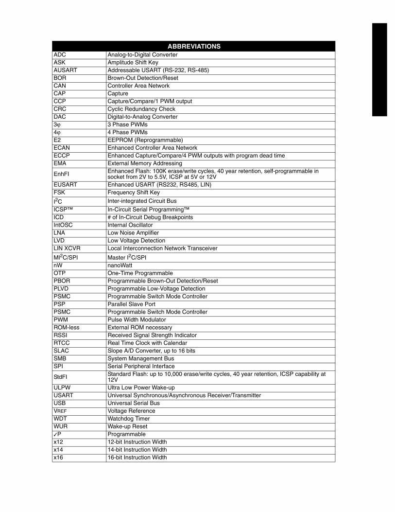
ABBREVIATIONSADC Analog-to-Digital ConverterASK Amplitude Shift KeyAUSART Addressable USART (RS-232, RS-485)BOR Brown-Out Detection/ResetCAN Controller Area NetworkCAP CaptureCCP Capture/Compare/1 PWM outputCRC Cyclic Redundancy CheckDAC Digital-to-Analog Converter3ϕ 3 Phase PWMs4ϕ 4 Phase PWMsE2 EEPROM (Reprogrammable)ECAN Enhanced Controller Area NetworkECCP Enhanced Capture/Compare/4 PWM outputs with program dead timeEMA External Memory Addressing
EnhFI Enhanced Flash: 100K erase/write cycles, 40 year retention, self-programmable in socket from 2V to 5.5V, ICSP at 5V or 12V
EUSART Enhanced USART (RS232, RS485, LIN)FSK Frequency Shift Key
I2C Inter-integrated Circuit Bus
ICSP™ In-Circuit Serial Programming™ICD # of In-Circuit Debug BreakpointsIntOSC Internal OscillatorLNA Low Noise AmplifierLVD Low Voltage DetectionLIN XCVR Local Interconnection Network Transceiver
MI2C/SPI Master I2C/SPInW nanoWattOTP One-Time ProgrammablePBOR Programmable Brown-Out Detection/ResetPLVD Programmable Low-Voltage DetectionPSMC Programmable Switch Mode ControllerPSP Parallel Slave PortPSMC Programmable Switch Mode ControllerPWM Pulse Width ModulatorROM-less External ROM necessaryRSSI Received Signal Strength IndicatorRTCC Real Time Clock with CalendarSLAC Slope A/D Converter, up to 16 bitsSMB System Management BusSPI Serial Peripheral Interface
StdFI Standard Flash: up to 10,000 erase/write cycles, 40 year retention, ICSP capability at 12V
ULPW Ultra Low Power Wake-upUSART Universal Synchronous/Asynchronous Receiver/TransmitterUSB Universal Serial BusVREF Voltage ReferenceWDT Watchdog TimerWUR Wake-up Reset✓P Programmablex12 12-bit Instruction Widthx14 14-bit Instruction Widthx16 16-bit Instruction Width

Microchip Technology’s Quality Policy
In order to meet or exceed customer expectations at a reduced cost, we encourage our employees to
support continuous improvement, anticipate problems and implement root cause solutions.
Aggregate Approach
Microchip has instituted an “aggregate” approach to understand, align, integrate and unite all company resources.
Microchip consciously designed the enterprise as an aggregate system in which company culture, systems,
practices, policies and employees work in unison to achieve Microchip’s mission and goals. This aggregate
system and culture is taught in the Microchip Culture class required for all new hires and taught by Executive Staff
members.
The Quality Culture of Microchip is that every organization, business unit and individual owns the quality of their
output, whether it is product, process, software or service.
A company must aggressively pursue continuous improvement, employee development, team deployment and
statistical techniques to successfully achieve individual accountability of quality.
Continuous Improvement
Microchip promotes a culture of continuous improvement. As stated above, each employee is measured on how
they contribute to improvement. Continuous improvement teams are constantly looking to solve problems, allowing
us to maximize our value to our customers.
Employee Development and Team Deployment
Every employee has access to a full suite of training. Each employee is measured on Quality and Quantity of work,
Teamwork, Continuous Improvement and Customer Satisfaction. Supervisors are measured on how their employees
improve and learn. Employees have regular One-on-Ones with their supervisors and open door is a policy that is
really practiced.
Statistical Techniques
Microchip uses statistical process techniques in all aspects of our business. Decision-making, experiment defi nition
and process control are a few areas where these techniques are applied. Every manufacturing employee is trained
in SPC before they start their job, since they are the people closest to the product quality.
QS-9000 Certifi cation
Microchip Technology’s Quality System is based on QS-9000 requirements. QS-9000 is rapidly becoming the
standard Quality System for many industries including Semiconductors. All Microchip product facilities and major
subcontractors are QS registered. Development Systems and Mountain View products are designed, manufactured
and certifi ed to ISO-9001 requirements.
Quality Systems and Reliability Information
Visit www.microchip.com for detailed Quality Systems and Reliability information.
Microchip’s Quality System is fully described in the Microchip Overview, Quality Systems and Customer
Interface Systems Handbook (DS00169) available on our web site.
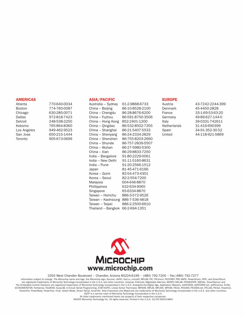
AMERICASAtlanta 770-640-0034 Boston 774-760-0087 Chicago 630-285-0071 Dallas 972-818-7423 Detroit 248-538-2250 Kokomo 765-864-8360 Los Angeles 949-462-9523 San Jose 650-215-1444 Toronto 905-673-0699
ASIA/PACIFICAustralia – Sydney 61-2-9868-6733 China – Beijing 86-10-8528-2100 China – Chengdu 86-28-8676-6200China – Fuzhou 86-591-8750-3506China – Hong Kong 852-2401-1200China – Qingdao 86-532-8502-7355 China – Shanghai 86-21-5407-5533China – Shenyang 86-24-2334-2829China – Shenzhen 86-755-8203-2660China – Shunde 86-757-2839-5507China – Wuhan 86-27-5980-5300China – Xian 86-29-8833-7250India – Bangalore 91-80-2229-0061India – New Delhi 91-11-5160-8631India – Pune 91-20-2566-1512 Japan 81-45-471-6166Korea – Gumi 82-54-473-4301 Korea – Seoul 82-2-554-7200Malaysia 604-646-8870Phillippines 632-634-9065 Singapore 65-6334-8870Taiwan – Hsinchu 886-3-572-9526Taiwan – Kaohsiung 886-7-536-4818Taiwan – Taipei 886-2-2500-6610Thailand – Bangkok 66-2-694-1351
EUROPEAustria 43-7242-2244-399Denmark 45-4450-2828 France 33-1-69-53-63-20 Germany 49-89-627-144-0 Italy 39-0331-742611Netherlands 31-416-690399Spain 34-91-352-30-52 United 44-118-921-5869
2355 West Chandler Boulevard • Chandler, Arizona 85224-6199 • (480) 792-7200 • Fax (480) 792-7277
www.microchip.com
Information subject to change. The Microchip name and logo, the Microchip logo, Accuron, dsPIC, KEELOQ, microID, MPLAB, PIC, PICmicro, PICSTART, PRO MATE, PowerSmart, rfPIC, and SmartShunt are registered trademarks of Microchip Technology Incorporated in the U.S.A. and other countries. AmpLab, FilterLab, Migratable Memory, MXDEV, MXLAB, PICMASTER, SEEVAL, SmartSensor and
The Embedded Control Solutions are registered trademarks of Microchip Technology Incorporated in the U.S.A. Analog-for-the-Digital Age, Application Maestro, dsPICDEM, dsPICDEM.net, dsPICworks, ECAN, ECONOMONITOR, FanSense, FlexROM, fuzzyLAB, In-Circuit Serial Programming, ICSP, ICEPIC, Linear Active Thermistor, MPASM, MPLIB, MPLINK, MPSIM, PICkit, PICDEM, PICDEM.net, PICLAB, PICtail, PowerCal,
PowerInfo, PowerMate, PowerTool, rfLab, Select Mode, Smart Serial, SmartTel, Total Endurance and WiperLock are trademarks of Microchip Technology Incorporated in the U.S.A. and other countries. SQTP is a service mark of Microchip Technology Incorporated in the U.S.A.
All other trademarks mentioned herein are property of their respective companies. ©2005 Microchip Technology Inc. All rights reserved. Printed in the U.S.A. 10/05 DS00148K4


![Web viewKészült a TAMOP-4.1.2.A/2-10/1 pályázati projekt keretében. ... 1980. Intel: 8051 ( On-board EPROM-mal) ... [Microchip Microcontroller Product Selector]:](https://img.pdfslide.net/doc/110x75/5a700db87f8b9abb538b95eb/wwwtankonyvtarhuwwwtankonyvtarhuhutartalomtamop412a2010-0017doc.jpg)