Embed Size (px)
Citation preview
Part #6-81 www.powercommander.com 2006-2016 Suzuki M109R / C109R - 1
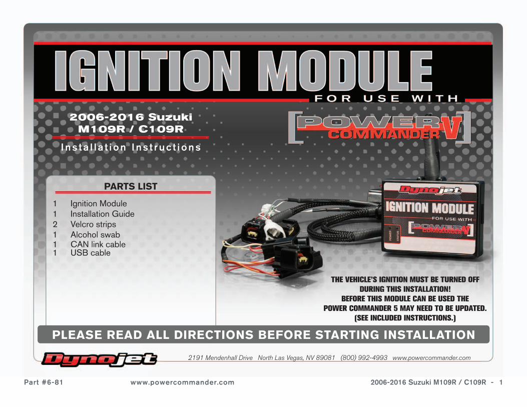
PARTS LIST
1 Ignition Module1 Installation Guide2 Velcro strips1 Alcohol swab1 CAN link cable1 USB cable
2006-2016 Suzuki M109R / C109R
I ns ta l l a t i on I ns t ruc t i ons
PLEASE READ ALL DIRECTIONS BEFORE STARTING INSTALLATION
2191 Mendenhall Drive North Las Vegas, NV 89081 (800) 992-4993 www.powercommander.com
THE VEHICLE’S IGNITION MUST BE TURNED OFF DURING THIS INSTALLATION!
BEFORE THIS MODULE CAN BE USED THEPOWER COMMANDER 5 MAY NEED TO BE UPDATED.
(SEE INCLUDED INSTRUCTIONS.)
Part #6-81 www.powercommander.com 2006-2016 Suzuki M109R / C109R - 2
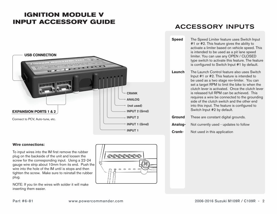
EXPANSION PORTS 1 & 2
Connect to PCV, Auto-tune, etc.
IGNITION MODULE V INPUT ACCESSORY GUIDE
Speed The Speed Limiter feature uses Switch Input #1 or #2. This feature gives the ability to activate a limiter based on vehicle speed. This is intended to be used as a pit lane speed limiter. You can use any OPEN / CLOSED type switch to activate this feature. The feature is configured to Switch Input #1 by default.
Launch The Launch Control feature also uses Switch Input #1 or #2. This feature is intended to be used as a two stage rev-limiter. You can set a target RPM to limit the bike to when the clutch lever is activated. Once the clutch lever is released full RPM can be achieved. This requires a wire be connected to the grounding side of the clutch switch and the other end into this input. The feature is configured to Switch Input #2 by default.
Ground These are constant digital grounds.
Analog- Not currently used - updates to follow
Crank- Not used in this application
ACCESSORY INPUTS
Wire connections:
To input wires into the IM first remove the rubber plug on the backside of the unit and loosen the screw for the corresponding input. Using a 22-24 gauge wire strip about 10mm from its end. Push the wire into the hole of the IM until is stops and then tighten the screw. Make sure to reinstall the rubber plug.
NOTE: If you tin the wires with solder it will make inserting them easier.
CRANK
ANALOG
(not used)
INPUT 1 (Grnd)
USB CONNECTION
INPUT 1
INPUT 2 (Grnd)
INPUT 2
Part #6-81 www.powercommander.com 2006-2016 Suzuki M109R / C109R - 3
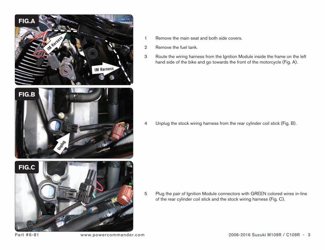
1 Remove the main seat and both side covers.
2 Remove the fuel tank.
3 Route the wiring harness from the Ignition Module inside the frame on the left hand side of the bike and go towards the front of the motorcycle (Fig. A).
4 Unplug the stock wiring harness from the rear cylinder coil stick (Fig. B).
5 Plug the pair of Ignition Module connectors with GREEN colored wires in-line of the rear cylinder coil stick and the stock wiring harness (Fig. C).
FIG.A
FIG.C
FIG.B
IM Harness
IM Harn
ess
Unplu
g
Part #6-81 www.powercommander.com 2006-2016 Suzuki M109R / C109R - 4
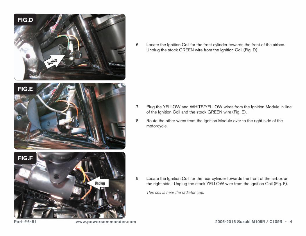
6 Locate the Ignition Coil for the front cylinder towards the front of the airbox. Unplug the stock GREEN wire from the Ignition Coil (Fig. D).
7 Plug the YELLOW and WHITE/YELLOW wires from the Ignition Module in-line of the Ignition Coil and the stock GREEN wire (Fig. E).
8 Route the other wires from the Ignition Module over to the right side of the motorcycle.
FIG.D
FIG.E
9 Locate the Ignition Coil for the rear cylinder towards the front of the airbox on the right side. Unplug the stock YELLOW wire from the Ignition Coil (Fig. F).
This coil is near the radiator cap.
FIG.F
Unplug
Unplug
Part #6-81 www.powercommander.com 2006-2016 Suzuki M109R / C109R - 5
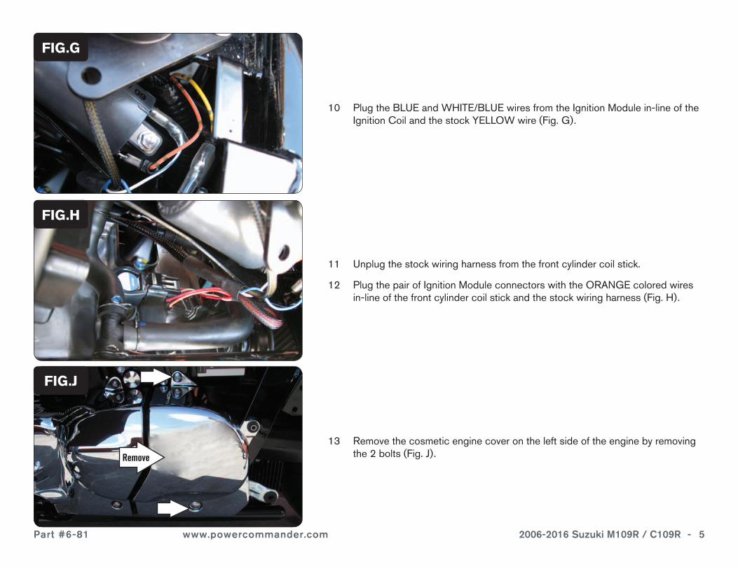
10 Plug the BLUE and WHITE/BLUE wires from the Ignition Module in-line of the Ignition Coil and the stock YELLOW wire (Fig. G).
11 Unplug the stock wiring harness from the front cylinder coil stick.
12 Plug the pair of Ignition Module connectors with the ORANGE colored wires in-line of the front cylinder coil stick and the stock wiring harness (Fig. H).
13 Remove the cosmetic engine cover on the left side of the engine by removing the 2 bolts (Fig. J).
FIG.G
FIG.J
FIG.H
Remove
Part #6-81 www.powercommander.com 2006-2016 Suzuki M109R / C109R - 6
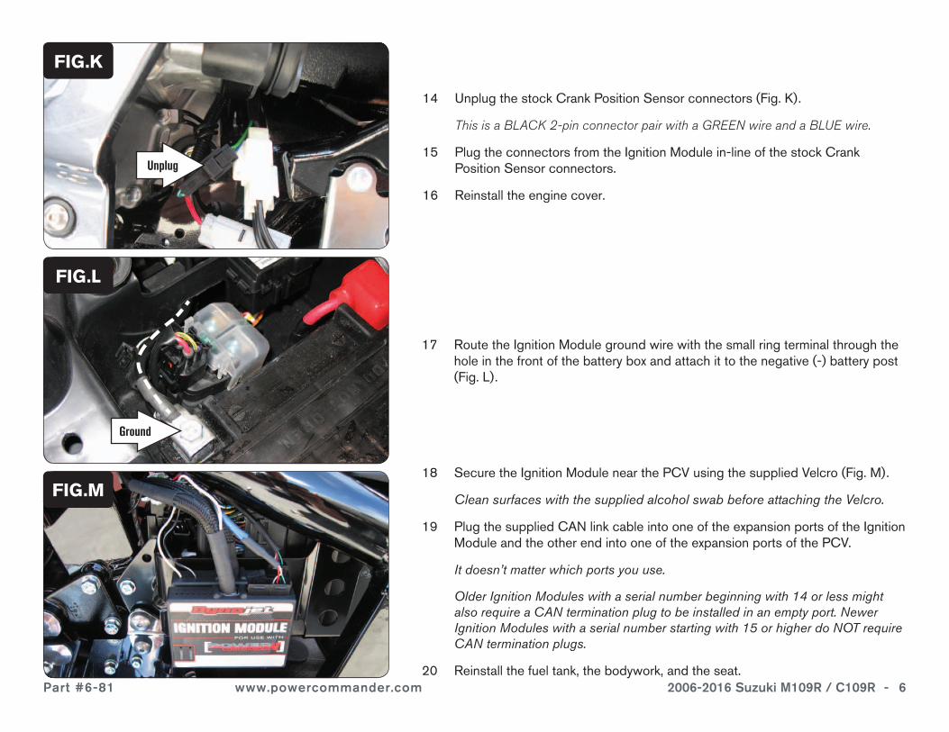
17 Route the Ignition Module ground wire with the small ring terminal through the hole in the front of the battery box and attach it to the negative (-) battery post (Fig. L).
18 Secure the Ignition Module near the PCV using the supplied Velcro (Fig. M).
Clean surfaces with the supplied alcohol swab before attaching the Velcro.
19 Plug the supplied CAN link cable into one of the expansion ports of the Ignition Module and the other end into one of the expansion ports of the PCV.
It doesn’t matter which ports you use.
Older Ignition Modules with a serial number beginning with 14 or less might also require a CAN termination plug to be installed in an empty port. Newer Ignition Modules with a serial number starting with 15 or higher do NOT require CAN termination plugs.
20 Reinstall the fuel tank, the bodywork, and the seat.
FIG.K
FIG.M
FIG.L
14 Unplug the stock Crank Position Sensor connectors (Fig. K).
This is a BLACK 2-pin connector pair with a GREEN wire and a BLUE wire.
15 Plug the connectors from the Ignition Module in-line of the stock Crank Position Sensor connectors.
16 Reinstall the engine cover.
Unplug
Ground
Part #6-81 www.powercommander.com 2006-2016 Suzuki M109R / C109R - 7
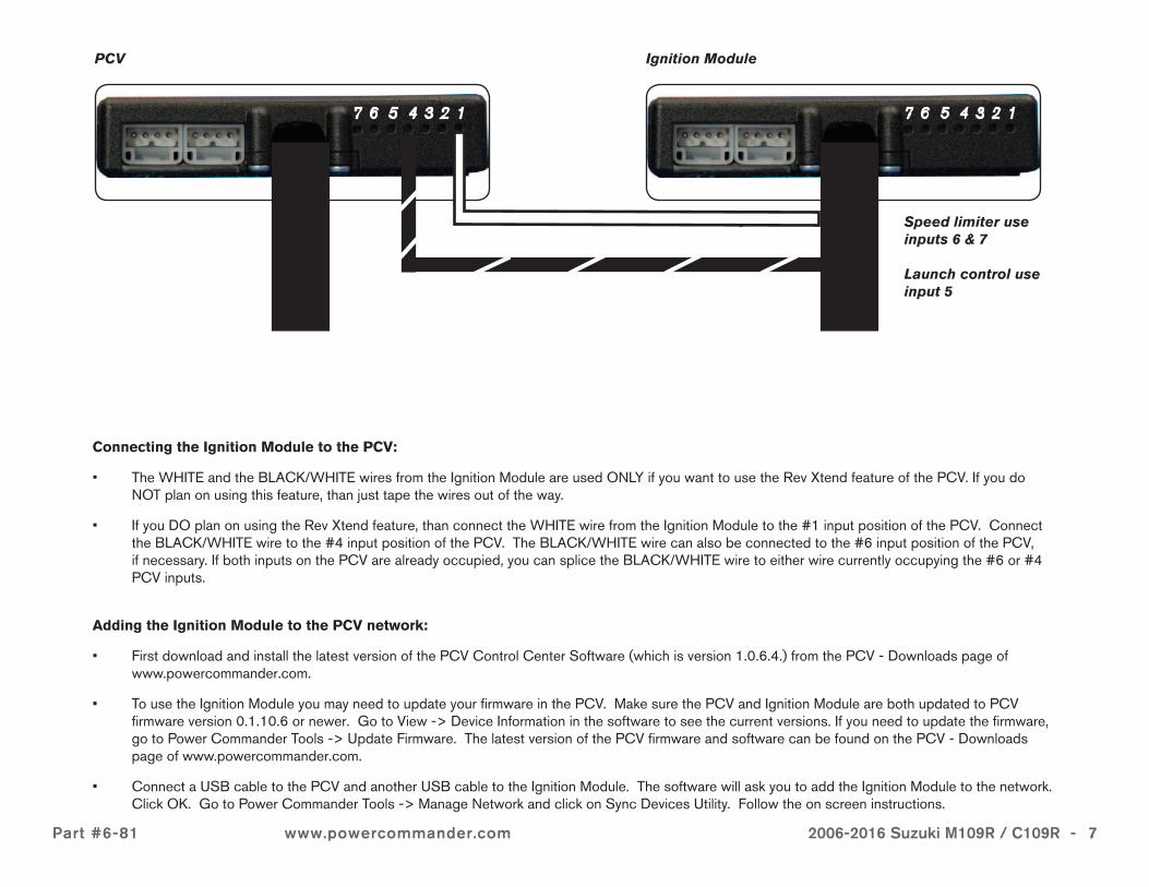
Connecting the Ignition Module to the PCV:
• The WHITE and the BLACK/WHITE wires from the Ignition Module are used ONLY if you want to use the Rev Xtend feature of the PCV. If you do NOT plan on using this feature, than just tape the wires out of the way.
• If you DO plan on using the Rev Xtend feature, than connect the WHITE wire from the Ignition Module to the #1 input position of the PCV. Connect the BLACK/WHITE wire to the #4 input position of the PCV. The BLACK/WHITE wire can also be connected to the #6 input position of the PCV, if necessary. If both inputs on the PCV are already occupied, you can splice the BLACK/WHITE wire to either wire currently occupying the #6 or #4 PCV inputs.
PCV Ignition Module
Adding the Ignition Module to the PCV network:
• First download and install the latest version of the PCV Control Center Software (which is version 1.0.6.4.) from the PCV - Downloads page of www.powercommander.com.
• To use the Ignition Module you may need to update your firmware in the PCV. Make sure the PCV and Ignition Module are both updated to PCV firmware version 0.1.10.6 or newer. Go to View -> Device Information in the software to see the current versions. If you need to update the firmware, go to Power Commander Tools -> Update Firmware. The latest version of the PCV firmware and software can be found on the PCV - Downloads page of www.powercommander.com.
• Connect a USB cable to the PCV and another USB cable to the Ignition Module. The software will ask you to add the Ignition Module to the network. Click OK. Go to Power Commander Tools -> Manage Network and click on Sync Devices Utility. Follow the on screen instructions.
Speed limiter use inputs 6 & 7
Launch control use input 5


![Coming Soon [] · Coming Soon "-cafe $ SUZUKI Kcafe $ SUZUKI — DAIHATSU G SAIII 7650km 069 $ SUZUKI 160 $ SUZUKI 774 $ SUZUKI "-cafe "-cafe Kcafe "cafe 1 0:00 19:00 o 120m $ SUZUKI](https://img.pdfslide.net/doc/110x75/5fcbd960711242011579771e/coming-soon-coming-soon-cafe-suzuki-kcafe-suzuki-a-daihatsu-g-saiii.jpg)