Embed Size (px)
Citation preview
2006 Accord Hybrid Online Reference Owner's Manual Use these links (and links throughout this manual) to navigate through this reference. For a printed owner's manual, click on authorized manuals or go to www.helminc.com.
Contents
Owner's Identification Form
Introduction ..................................................................................................................................................... i
A Few Words About Safety .......................................................................................................................... ii
Your Vehicle at a Glance ...............................................................................................................................4Driver and Passenger Safety .......................................................................................................................7Proper use and care of your vehicle's seat belts, and Supplemental Restraint System.
Instruments and Controls...........................................................................................................................51Instrument panel indicator and gauge, and how to use dashboard and steering column controls.
Comfort and Convenience Features....................................................................................................... 99How to operate the climate control system, the audio system, and other convenience features.
Before Driving .............................................................................................................................................149What gasoline to use, how to break-in your new vehicle, and how to load luggage and other cargo.
Driving ...........................................................................................................................................................163The proper way to start the engine, shift the transmission, and park, plus towing a trailer.
Maintenance .................................................................................................................................................185The Maintenance Schedule shows you when you need to take your vehicle to the dealer.
Taking Care of the Unexpected...............................................................................................................225This section covers several problems motorists sometimes experience, and how to handle them.
Technical Information ...............................................................................................................................249ID numbers, dimensions, capacities, and technical information.
Warranty and Customer Relations (U.S. and Canada) ..................................................................... 263A summary of the warranties covering your new Honda, and how to contact us.
Authorized Manuals (U.S. only)...............................................................................................................267How to order manuals and other technical literature.
Index ................................................................................................................................................................. I
Service Information Summary A summary of information you need when you pull up to the fuel pump.
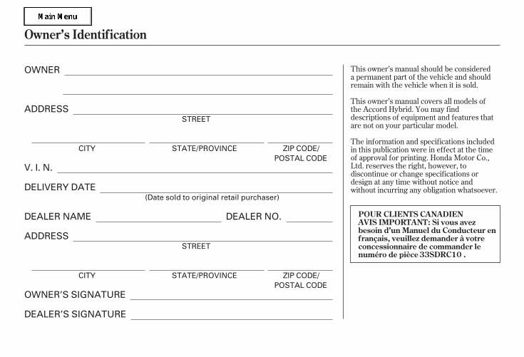
The information and specifications includedin this publication were in effect at the timeof approval for printing. Honda Motor Co.,Ltd. reserves the right, however, todiscontinue or change specifications ordesign at any time without notice andwithout incurring any obligation whatsoever.
This owner’s manual should be considereda permanent part of the vehicle and shouldremain with the vehicle when it is sold.
This owner’s manual covers all models ofthe Accord Hybrid. You may finddescriptions of equipment and features thatare not on your particular model.
Owner’s Identif ication
POUR CLIENTS CANADIENAVIS IMPORTANT: Si vous avezbesoin d’un Manuel du Conducteur enfrançais, veuillez demander à votreconcessionnaire de commander lenuméro de pièce 33SDRC10 .
OWNER
ADDRESS
V. I. N.
DELIVERY DATE
DEALER NAME DEALER NO.
ADDRESS
OWNER’S SIGNATURE
DEALER’S SIGNATURE
STREET
CITY STATE/PROVINCE ZIP CODE/POSTAL CODE
(Date sold to original retail purchaser)
STREET
CITY STATE/PROVINCE ZIP CODE/POSTAL CODE
05/09/02 11:34:19 31SDR610 0001
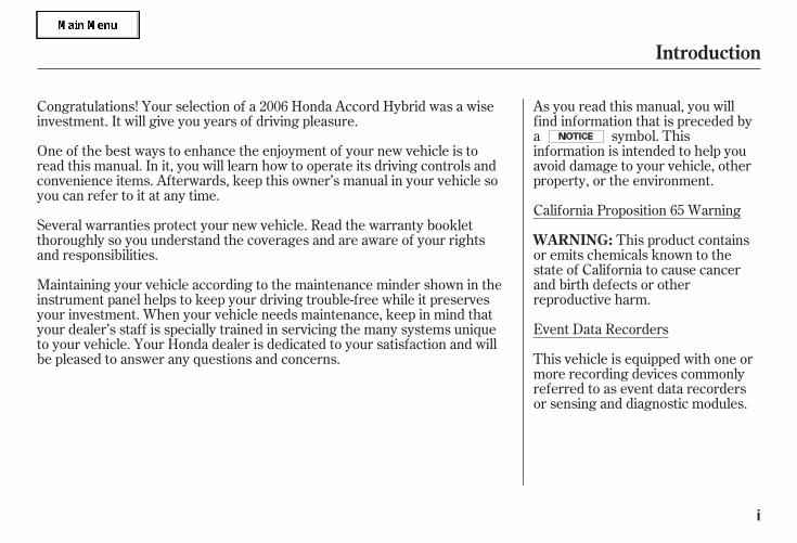
California Proposition 65 Warning
This product containsor emits chemicals known to thestate of California to cause cancerand birth defects or otherreproductive harm.
Event Data Recorders
This vehicle is equipped with one ormore recording devices commonlyreferred to as event data recordersor sensing and diagnostic modules.
One of the best ways to enhance the enjoyment of your new vehicle is toread this manual. In it, you will learn how to operate its driving controls andconvenience items. Afterwards, keep this owner’s manual in your vehicle soyou can refer to it at any time.
Several warranties protect your new vehicle. Read the warranty bookletthoroughly so you understand the coverages and are aware of your rightsand responsibilities.
As you read this manual, you willfind information that is preceded bya symbol. Thisinformation is intended to help youavoid damage to your vehicle, otherproperty, or the environment.
Congratulations! Your selection of a 2006 Honda Accord Hybrid was a wiseinvestment. It will give you years of driving pleasure.
Maintaining your vehicle according to the maintenance minder shown in theinstrument panel helps to keep your driving trouble-free while it preservesyour investment. When your vehicle needs maintenance, keep in mind thatyour dealer’s staff is specially trained in servicing the many systems uniqueto your vehicle. Your Honda dealer is dedicated to your satisfaction and willbe pleased to answer any questions and concerns.
Introduction
WARNING:
i
05/09/02 11:34:25 31SDR610 0002
-
-
--
-
-
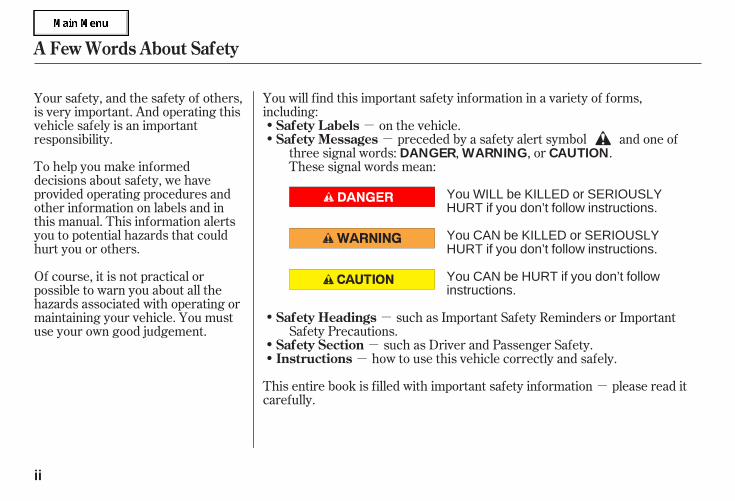
To help you make informeddecisions about safety, we haveprovided operating procedures andother information on labels and inthis manual. This information alertsyou to potential hazards that couldhurt you or others.
You will find this important safety information in a variety of forms,including:
preceded by a safety alert symbol and one ofthree signal words: , , or .These signal words mean:
such as Important Safety Reminders or ImportantSafety Precautions.
such as Driver and Passenger Safety.how to use this vehicle correctly and safely.
This entire book is filled with important safety information please read itcarefully.
Your safety, and the safety of others,is very important. And operating thisvehicle safely is an importantresponsibility.
Of course, it is not practical orpossible to warn you about all thehazards associated with operating ormaintaining your vehicle. You mustuse your own good judgement.
on the vehicle.
A Few Words About Safety
Safety Messages
Safety Headings
Safety SectionInstructions
Safety Labels
DANGER WARNING CAUTION
ii
You WILL be KILLED or SERIOUSLYHURT if you don’t follow instructions.
You CAN be KILLED or SERIOUSLYHURT if you don’t follow instructions.
You CAN be HURT if you don’t followinstructions.
05/09/02 11:34:34 31SDR610 0003
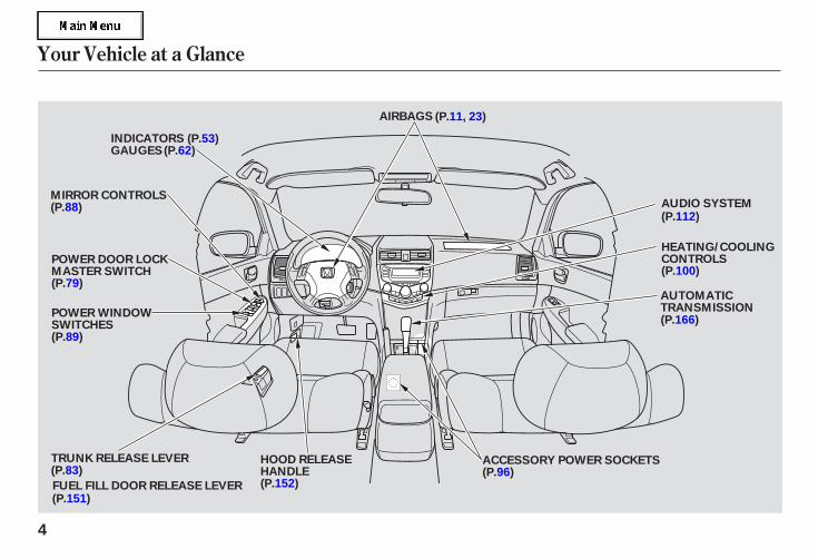
Your Vehicle at a Glance
4
HEATING/COOLINGCONTROLS
MIRROR CONTROLS
POWER WINDOWSWITCHES
GAUGES
HOOD RELEASEHANDLE
ACCESSORY POWER SOCKETS
AUDIO SYSTEM
AUTOMATICTRANSMISSION
AIRBAGS (P.11, 23)
INDICATORS
TRUNK RELEASE LEVER
FUEL FILL DOOR RELEASE LEVER
(P.53)
(P.112)
(P.100)
(P.62)
(P.88)
POWER DOOR LOCKMASTER SWITCH(P.79)
(P.89)
(P.83)
(P.151)
(P.152)(P.96)
(P.166)
05/09/02 11:35:08 31SDR610 0007
*
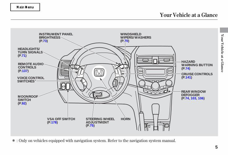
* Only on vehicles equipped with navigation system. Refer to the navigation system manual.:
Your Vehicle at a Glance
Your
Vehicle
ataG
lance
5
WINDSHIELDWIPERS/WASHERS
INSTRUMENT PANELBRIGHTNESS
VOICE CONTROLSWITCHES
HEADLIGHTS/TURN SIGNALS
REMOTE AUDIOCONTROLS
HORNSTEERING WHEELADJUSTMENT
CRUISE CONTROLS
REAR WINDOWDEFOGGER
HAZARDWARNING BUTTON
VSA OFF SWITCH
(P.73)
(P.71)
(P.137)
(P.178)(P.75)
(P.74, 103, 106)
(P.141)
(P.74)
(P.70)
MOONROOFSWITCH(P.92)
05/09/02 11:35:13 31SDR610 0008

-
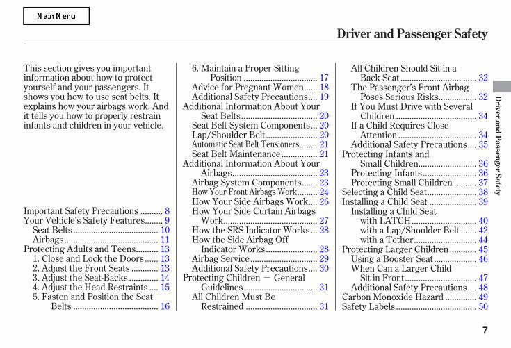
This section gives you importantinformation about how to protectyourself and your passengers. Itshows you how to use seat belts. Itexplains how your airbags work. Andit tells you how to properly restraininfants and children in your vehicle.
.........Important Safety Precautions . 8.......Your Vehicle’s Safety Features . 9
.....................................Seat Belts . 10.........................................Airbags . 11
.........Protecting Adults and Teens . 13.....1. Close and Lock the Doors . 13
...........2. Adjust the Front Seats . 13............3. Adjust the Seat-Backs . 14
...4. Adjust the Head Restraints . 155. Fasten and Position the Seat
.....................................Belts . 16
6. Maintain a Proper Sitting................................Position . 17
.....Advice for Pregnant Women . 18...Additional Safety Precautions . 19
Additional Information About Your.................................Seat Belts . 20
..Seat Belt System Components . 20......................Lap/Shoulder Belt . 20
........ 21...............Seat Belt Maintenance . 21
Additional Information About Your.....................................Airbags . 23
......Airbag System Components . 23......... 24
...How Your Side Airbags Work . 26How Your Side Curtain Airbags
.........................................Work . 27..How the SRS Indicator Works . 28
How the Side Airbag Off......................Indicator Works . 28
.............................Airbag Service . 29...Additional Safety Precautions . 30
Protecting Children General................................Guidelines . 31
All Children Must Be...............................Restrained . 31
All Children Should Sit in a.................................Back Seat . 32
The Passenger’s Front Airbag................Poses Serious Risks . 32
If You Must Drive with Several...................................Children . 34
If a Child Requires Close..................................Attention . 34
...Additional Safety Precautions . 35Protecting Infants and
.........................Small Children . 36.......................Protecting Infants . 36
.........Protecting Small Children . 37.....................Selecting a Child Seat . 38....................Installing a Child Seat . 39
Installing a Child Seat............................with LATCH . 40
......with a Lap/Shoulder Belt . 42...........................with a Tether . 44
...........Protecting Larger Children . 45..................Using a Booster Seat . 46
When Can a Larger Child...............................Sit in Front . 47
...Additional Safety Precautions . 48.............Carbon Monoxide Hazard . 49
...................................Safety Labels . 50
Automatic Seat Belt Tensioners
How Your Front Airbags Work
Driver and Passenger Safety
Driver
andP
assengerSafety
7
05/09/02 11:35:20 31SDR610 0010
-
You’ll find many safetyrecommendations throughout thissection, and throughout this manual.The recommendations on this pageare the ones we consider to be themost important.
Excessive speed is a major factor incrash injuries and deaths. Generally,the higher the speed, the greater therisk, but serious injuries can alsooccur at lower speeds. Never drivefaster than is safe for currentconditions, regardless of themaximum speed posted.
Having a tire blowout or amechanical failure can be extremelyhazardous. To reduce the possibilityof such problems, check your tirepressures and condition frequently,and perform all regularly scheduledmaintenance (see page ).
A seat belt is your best protection inall types of collisions. Airbags aredesigned to supplement seat belts,not replace them. So even thoughyour vehicle is equipped with airbags,make sure you and your passengersalways wear your seat belts, andwear them properly (see page ).
Children age 12 and under shouldride properly restrained in a backseat. Infants and small childrenshould be restrained in a child seat.Larger children should use a boosterand a lap/shoulder belt until theycan use the belt properly without abooster (see pages ).
While airbags can save lives, theycan cause serious or fatal injuries tooccupants who sit too close to them,or are not properly restrained.Infants, young children, and shortadults are at the greatest risk. Besure to follow all instructions andwarnings in this manual.
Alcohol and driving don’t mix. Evenone drink can reduce your ability torespond to changing conditions, andyour reaction time gets worse withevery additional drink. So don’t drinkand drive, and don’t let your friendsdrink and drive, either.
16
4831
185
Important Safety Precautions
Always Wear Your Seat Belt
Control Your Speed
Keep Your Vehicle in SafeCondition
Restrain All Children
Be Aware of Airbag Hazards
Don’t Drink and Drive
8
05/09/02 11:35:30 31SDR610 0011
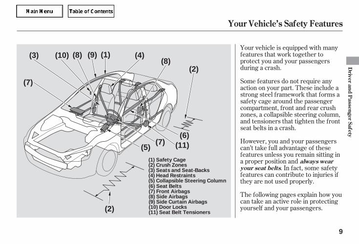
Your vehicle is equipped with manyfeatures that work together toprotect you and your passengersduring a crash.
The following pages explain how youcan take an active role in protectingyourself and your passengers.
However, you and your passengerscan’t take full advantage of thesefeatures unless you remain sitting ina proper position and
. In fact, some safetyfeatures can contribute to injuries ifthey are not used properly.
Some features do not require anyaction on your part. These include astrong steel framework that forms asafety cage around the passengercompartment, front and rear crushzones, a collapsible steering column,and tensioners that tighten the frontseat belts in a crash.
Your Vehicle’s Safety Features
always wearyour seat belts
Driver
andP
assengerSafety
9
(1)
(2)
(2)
(3) (4)
(5)
(6)(7)
(8)
(7)
(10)
(11)
(9)(8)
(1) Safety Cage(2) Crush Zones(3) Seats and Seat-Backs(4) Head Restraints(5) Collapsible Steering Column(6) Seat Belts(7) Front Airbags(8) Side Airbags(9) Side Curtain Airbags(10) Door Locks(11) Seat Belt Tensioners
05/09/02 11:35:37 31SDR610 0012
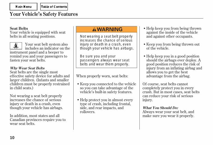
Your vehicle is equipped with seatbelts in all seating positions.
Seat belts are the single mosteffective safety device for adults andlarger children. (Infants and smallerchildren must be properly restrainedin child seats.)
In addition, most states and allCanadian provinces require you towear seat belts.
Not wearing a seat belt properlyincreases the chance of seriousinjury or death in a crash, eventhough your vehicle has airbags.
Keep you connected to the vehicleso you can take advantage of thevehicle’s built-in safety features.
When properly worn, seat belts:
Help keep you from being thrownagainst the inside of the vehicleand against other occupants.
Keep you from being thrown outof the vehicle.
Help keep you in a good positionshould the airbags ever deploy. Agood position reduces the risk ofinjury from an inflating airbag andallows you to get the bestadvantage from the airbag.
Of course, seat belts cannotcompletely protect you in everycrash. But in most cases, seat beltscan reduce your risk of seriousinjury.
Always wear your seat belt, andmake sure you wear it properly.
Your seat belt system alsoincludes an indicator on the
instrument panel and a beeper toremind you and your passengers tofasten your seat belts.
Help protect you in almost everytype of crash, including frontal,side, and rear impacts, androllovers.
Seat Belts
Why Wear Seat Belts
What You Should Do:
Your Vehicle’s Safety Features
10
Not wearing a seat belt properlyincreases the chance of seriousinjury or death in a crash, eventhough your vehicle has airbags.
Be sure you and yourpassengers always wear seatbelts and wear them properly.
05/09/02 11:35:47 31SDR610 0013
CONTINUED
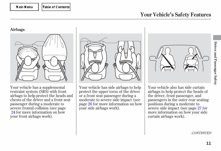
Your vehicle has a supplementalrestraint system (SRS) with frontairbags to help protect the heads andchests of the driver and a front seatpassenger during a moderate tosevere frontal collision (see page
for more information on howyour front airbags work).
Your vehicle has side airbags to helpprotect the upper torso of the driveror a front seat passenger during amoderate to severe side impact (seepage for more information on howyour side airbags work).
Your vehicle also has side curtainairbags to help protect the heads ofthe driver, front passenger, andpassengers in the outer rear seatingpositions during a moderate tosevere side impact (see page formore information on how your sidecurtain airbags work).
2427
26
Your Vehicle’s Safety Features
Airbags
Driver
andP
assengerSafety
11
05/09/02 11:35:54 31SDR610 0014
The most important things you needto know about your airbags are:
To dotheir job, airbags must inflate withtremendous force. So whileairbags help save lives, they cancause minor injuries or moreserious or even fatal injuries ifoccupants are not properlyrestrained or sitting properly.
Always wearyour seat belt properly, and situpright and as far back from thesteering wheel as possible whileallowing full control of the vehicle. Afront passenger should move theirseat as far back from the dashboardas possible.
The rest of this section gives moredetailed information about how youcan maximize your safety.
Remember, however, that no safetysystem can prevent all injuries ordeaths that can occur in a severecrash, even when seat belts areproperly worn and the airbags deploy.
They are designed to supplementthe seat belts.
Your Vehicle’s Safety Features
Airbags can pose hazards.
What you should do:
Airbags do not replace seat belts.
Airbags offer no protection in rearimpacts, or minor frontal or sidecollisions.
12
05/09/02 11:36:00 31SDR610 0015
-
CONTINUED
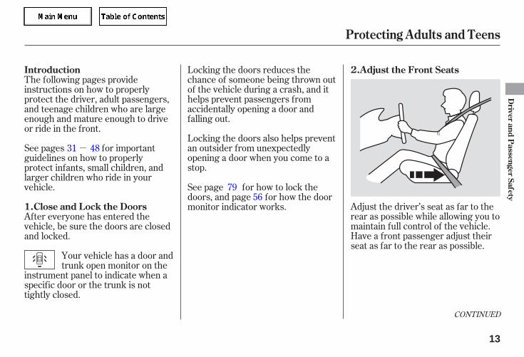
Adjust the driver’s seat as far to therear as possible while allowing you tomaintain full control of the vehicle.Have a front passenger adjust theirseat as far to the rear as possible.
Locking the doors reduces thechance of someone being thrown outof the vehicle during a crash, and ithelps prevent passengers fromaccidentally opening a door andfalling out.
Locking the doors also helps preventan outsider from unexpectedlyopening a door when you come to astop.
The following pages provideinstructions on how to properlyprotect the driver, adult passengers,and teenage children who are largeenough and mature enough to driveor ride in the front.
See pages for importantguidelines on how to properlyprotect infants, small children, andlarger children who ride in yourvehicle.
After everyone has entered thevehicle, be sure the doors are closedand locked.
See page for how to lock thedoors, and page for how the doormonitor indicator works.
Your vehicle has a door andtrunk open monitor on the
instrument panel to indicate when aspecific door or the trunk is nottightly closed.
48
5679
31
Protecting Adults and Teens
Introduction Adjust the Front Seats
Close and Lock the Doors1.
2.
Driver
andP
assengerSafety
13
05/09/02 11:36:10 31SDR610 0016
If you sit too close to the steeringwheel or dashboard, you can beseriously injured by an inflating frontairbag, or by striking the steeringwheel or dashboard.
The National Highway Traffic SafetyAdministration and TransportCanada recommend that driversallow at least 10 inches (25 cm)between the center of the steeringwheel and the chest. In addition toadjusting the seat, you can adjust thesteering wheel in and out (see page
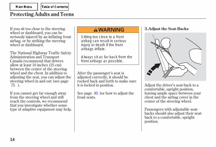
). Adjust the driver’s seat-back to acomfortable, upright position,leaving ample space between yourchest and the airbag cover in thecenter of the steering wheel.
Passengers with adjustable seat-backs should also adjust their seat-back to a comfortable, uprightposition.
If you cannot get far enough awayfrom the steering wheel and stillreach the controls, we recommendthat you investigate whether sometype of adaptive equipment may help.
After the passenger’s seat isadjusted correctly, it should berocked back and forth to make sureit is locked in position.
See page for how to adjust thefront seats.
75
85
Protecting Adults and Teens
Adjust the Seat-Backs3.
14
Sitting too close to a frontairbag can result in seriousinjury or death if the frontairbags inflate.
Always sit as far back from thefront airbags as possible.
05/09/02 11:36:18 31SDR610 0017
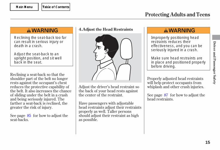
Adjust the driver’s head restraint sothe back of your head rests againstthe center of the restraint.
Have passengers with adjustablehead restraints adjust their restraintsproperly as well. Taller personsshould adjust their restraint as highas possible.
Properly adjusted head restraintswill help protect occupants fromwhiplash and other crash injuries.
See page for how to adjust thehead restraints.
See page for how to adjust theseat-backs.
Reclining a seat-back so that theshoulder part of the belt no longerrests against the occupant’s chestreduces the protective capability ofthe belt. It also increases the chanceof sliding under the belt in a crashand being seriously injured. Thefarther a seat-back is reclined, thegreater the risk of injury.
85
87
Protecting Adults and Teens
Adjust the Head Restraints4.
Driver
andP
assengerSafety
15
Reclining the seat-back too farcan result in serious injury ordeath in a crash.
Adjust the seat-back to anupright position, and sit wellback in the seat.
Improperly positioning headrestraints reduces theireffectiveness, and you can beseriously injured in a crash.
Make sure head restraints arein place and positioned properlybefore driving.
05/09/02 11:36:25 31SDR610 0018
If the seat belt touches or crossesyour neck, or if it crosses your arminstead of your shoulder, you need toadjust the seat belt anchor height.
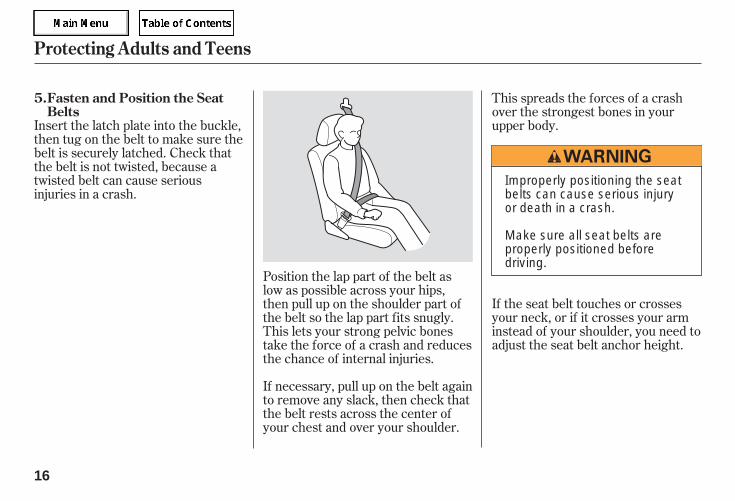
Insert the latch plate into the buckle,then tug on the belt to make sure thebelt is securely latched. Check thatthe belt is not twisted, because atwisted belt can cause seriousinjuries in a crash.
This spreads the forces of a crashover the strongest bones in yourupper body.
Position the lap part of the belt aslow as possible across your hips,then pull up on the shoulder part ofthe belt so the lap part fits snugly.This lets your strong pelvic bonestake the force of a crash and reducesthe chance of internal injuries.
If necessary, pull up on the belt againto remove any slack, then check thatthe belt rests across the center ofyour chest and over your shoulder.
Protecting Adults and Teens
Fasten and Position the SeatBelts
5.
16
Improperly positioning the seatbelts can cause serious injuryor death in a crash.
Make sure all seat belts areproperly positioned beforedriving.
05/09/02 11:36:32 31SDR610 0019
After all occupants have adjustedtheir seats and put on seat belts, it isvery important that they continue tosit upright, well back in their seats,with their feet on the floor, until thevehicle is parked and the engine isoff.
Sitting improperly can increase thechance of injury during a crash. Forexample, if an occupant slouches,lies down, turns sideways, sitsforward, leans forward or sideways,or puts one or both feet up, thechance of injury during a crash isgreatly increased.
This could causevery serious injuries in a crash.
See page for additionalinformation about your seat beltsand how to take care of them.
If a seat belt does not seem to workproperly, it may not protect theoccupant in a crash.
Using a seatbelt that is not working properly canresult in serious injury or death.Have your dealer check the belt assoon as possible.
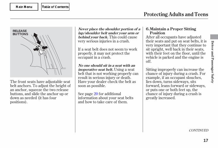
The front seats have adjustable seatbelt anchors. To adjust the height ofan anchor, squeeze the two releasebuttons, and slide the anchor up ordown as needed (it has fourpositions).
20
CONTINUED
Maintain a Proper SittingPosition
6.
Protecting Adults and Teens
Never place the shoulder portion of alap/shoulder belt under your arm orbehind your back.
No one should sit in a seat with aninoperative seat belt.
Driver
andP
assengerSafety
17
RELEASEBUTTONS
05/09/02 11:36:41 31SDR610 0020
When driving, remember to situpright and adjust the seat as farback as possible while allowing fullcontrol of the vehicle. When ridingas a front passenger, adjust the seatas far back as possible.
This will reduce the risk of injuriesto both you and your unborn childthat can be caused by a crash or aninflating front airbag.
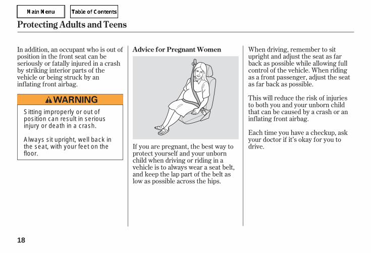
Each time you have a checkup, askyour doctor if it’s okay for you todrive.If you are pregnant, the best way to
protect yourself and your unbornchild when driving or riding in avehicle is to always wear a seat belt,and keep the lap part of the belt aslow as possible across the hips.
In addition, an occupant who is out ofposition in the front seat can beseriously or fatally injured in a crashby striking interior parts of thevehicle or being struck by aninflating front airbag.
Protecting Adults and Teens
Advice for Pregnant Women
18
Sitting improperly or out ofposition can result in seriousinjury or death in a crash.
Always sit upright, well back inthe seat, with your feet on thefloor.
05/09/02 11:36:47 31SDR610 0021

If yourhands or arms are close to anairbag cover, they could be injuredif the airbag inflates.
Objects onthe covers marked ‘‘SRS AIRBAG’’could interfere with the properoperation of the airbags or bepropelled inside the vehicle andhurt someone if the airbags inflate.
If they do, theycould be very seriously injured in acrash.
Carrying hard or sharpobjects on your lap, or driving witha pipe or other sharp object inyour mouth, can result in injuriesif your front airbag inflates.
Devices intended to improveoccupant comfort or reposition theshoulder part of a seat belt canreduce the protective capability ofthe belt and increase the chance ofserious injury in a crash.
If a side airbag or aside curtain airbag inflates, a cupholder or other hard objectattached on or near the door couldbe propelled inside the vehicle andhurt someone.
Protecting Adults and Teens
Keep your hands and arms awayfrom the airbag covers.
Do not attach or place objects onthe front airbag covers.
Two people should never use thesame seat belt.
Do not place hard or sharp objectsbetween yourself and a frontairbag.
Do not put any accessories on seatbelts.
Do not attach hard objects on ornear a door.
Additional Safety Precautions
Driver
andP
assengerSafety
19
05/09/02 11:36:53 31SDR610 0022
Your seat belt system includes lap/shoulder belts in all five seatingpositions. The front seat belts arealso equipped with automatic seatbelt tensioners.
The seat belt systemincludes an indicator on the
instrument panel and a beeper toremind you to fasten your seat belt.
If you turn the ignition switch to ON(II) before fastening your belt, thebeeper will sound and the indicatorwill flash.
The lap and shoulder belt goes overyour shoulder, across your chest,and across your hips.
To fasten the belt, insert the latchplate into the buckle, then tug on thebelt to make sure the buckle islatched (see page for how toproperly position the belt).
To unlock the belt, press the redPRESS button on the buckle. Guidethe belt across your body so that itretracts completely. After exiting thevehicle, be sure the belt is out of theway and will not get closed in thedoor.
All seat belts have an emergencylocking retractor. In normal driving,the retractor lets you move freely inyour seat while it keeps sometension on the belt. During a collisionor sudden stop, the retractorautomatically locks the belt to help
restrain your body.
The seat belts in all positions exceptthe driver’s have an additionallocking mechanism that must beactivated to secure a child seat (seepage ).
If the shoulder part of the belt ispulled all the way out, the lockingmechanism will activate. The beltwill retract, but it will not allow thepassenger to move freely.
To deactivate the lockingmechanism, unlatch the buckle andlet the seat belt fully retract. Torefasten the seat belt, pull it out onlyas far as needed.
If you continue driving withoutfastening your seat belt, the beeperwill sound and the indicator will flashagain at regular intervals.
If you do not fasten your seat beltbefore the beeper stops, theindicator will stop flashing butremain on.
16
42
Additional Information About Your Seat Belts
Seat Belt System Components Lap/Shoulder Belt
20
05/09/02 11:37:02 31SDR610 0023
CONTINUED
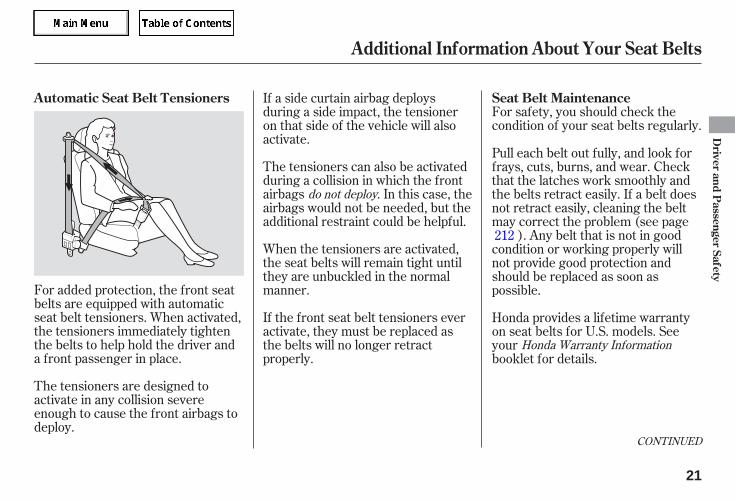
For added protection, the front seatbelts are equipped with automaticseat belt tensioners. When activated,the tensioners immediately tightenthe belts to help hold the driver anda front passenger in place.
For safety, you should check thecondition of your seat belts regularly.
The tensioners are designed toactivate in any collision severeenough to cause the front airbags todeploy.
If a side curtain airbag deploysduring a side impact, the tensioneron that side of the vehicle will alsoactivate.
The tensioners can also be activatedduring a collision in which the frontairbags . In this case, theairbags would not be needed, but theadditional restraint could be helpful.
When the tensioners are activated,the seat belts will remain tight untilthey are unbuckled in the normalmanner.
If the front seat belt tensioners everactivate, they must be replaced asthe belts will no longer retractproperly.
Pull each belt out fully, and look forfrays, cuts, burns, and wear. Checkthat the latches work smoothly andthe belts retract easily. If a belt doesnot retract easily, cleaning the beltmay correct the problem (see page
). Any belt that is not in goodcondition or working properly willnot provide good protection andshould be replaced as soon aspossible.
Honda provides a lifetime warrantyon seat belts for U.S. models. Seeyourbooklet for details.
212
do not deploy
Honda Warranty Information
Additional Information About Your Seat Belts
Seat Belt MaintenanceAutomatic Seat Belt Tensioners
Driver
andP
assengerSafety
21
05/09/02 11:37:12 31SDR610 0024
If a seat belt is worn during a crash,it must be replaced by the dealer. Abelt that has been worn during acrash may not provide the same levelof protection in a subsequent crash.
The dealer should also inspect theanchors for damage and replacethem if needed. If the automatic seatbelt tensioners activate during acrash, they must be replaced.
Additional Information About Your Seat Belts
22
Not checking or maintainingseat belts can result in seriousinjury or death if the seat beltsdo not work properly whenneeded.
Check your seat belts regularlyand have any problemcorrected as soon as possible.
05/09/02 11:37:16 31SDR610 0025
Your airbag system includes:A sophisticated electronic systemthat continually monitors andrecords information about thesensors, the control unit, theairbag activators, the seat belttensioners, and driver and frontpassenger seat belt use when theignition switch is in the ON (II)position.
Two side curtain airbags, one foreach side of the vehicle. Theairbags are stored in the ceiling,above the side windows. The frontand rear pillars are marked ‘‘SIDECURTAIN AIRBAG’’ (see page
).
Two side airbags, one for thedriver and one for a frontpassenger. The airbags are storedin the outer edges of the seat-backs. Both are marked ‘‘SIDEAIRBAG’’ (see page ).
Two SRS (supplemental restraintsystem) front airbags. The driver’sairbag is stored in the center ofthe steering wheel; the frontpassenger’s airbag is stored in thedashboard. Both are marked ‘‘SRSAIRBAG’’ (see page ).
Automatic front seat belttensioners (see page ).
Sensors that can detect amoderate to severe frontal or sideimpact.
Sensors that can detect whethera child is in the passenger’s sideairbag path and signal thecontrol unit to turn the airbagoff (see page ).
Emergency backup power in caseyour vehicle’s electrical system isdisconnected in a crash.
An indicator on the instrumentpanel that alerts you that thepassenger’s side airbag has beenturned off (see page ).
An indicator on the instrumentpanel that alerts you to a possibleproblem with your airbags,sensors, or seat belt tensioners(see page ).
27
21
26
28
26
28
24
Airbag System Components
Additional Information About Your Airbags
Driver
andP
assengerSafety
23
05/09/02 11:37:26 31SDR610 0026
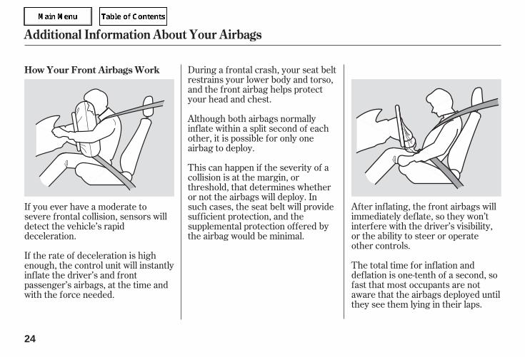
After inflating, the front airbags willimmediately deflate, so they won’tinterfere with the driver’s visibility,or the ability to steer or operateother controls.
The total time for inflation anddeflation is one-tenth of a second, sofast that most occupants are notaware that the airbags deployed untilthey see them lying in their laps.
During a frontal crash, your seat beltrestrains your lower body and torso,and the front airbag helps protectyour head and chest.
Although both airbags normallyinflate within a split second of eachother, it is possible for only oneairbag to deploy.
This can happen if the severity of acollision is at the margin, orthreshold, that determines whetheror not the airbags will deploy. Insuch cases, the seat belt will providesufficient protection, and thesupplemental protection offered bythe airbag would be minimal.
If you ever have a moderate tosevere frontal collision, sensors willdetect the vehicle’s rapiddeceleration.
If the rate of deceleration is highenough, the control unit will instantlyinflate the driver’s and frontpassenger’s airbags, at the time andwith the force needed.
How Your Front Airbags Work
Additional Information About Your Airbags
24
05/09/02 11:37:34 31SDR610 0027
Your front airbags are also dual-threshold airbags. Airbags with thisfeature have two deploymentthresholds that depend on whetheror not the occupant is wearing a seatbelt.
If the occupant’s belt is ,the airbag will deploy at a slightlylower threshold, because theoccupant would need extraprotection.
Your front airbags are dual-stageairbags. This means they have twoinflation stages that can be ignitedsequentially or simultaneously,depending on crash severity.
In a crash, both stageswill ignite simultaneously to providethe quickest and greatest protection.
In a crash, one stage willignite first, then the second stagewill ignite a split second later. Thisprovides longer airbag inflation timewith a little less force.
After a crash, you may see whatlooks like smoke. This is actuallypowder from the airbag’s surface.Although the powder is not harmful,people with respiratory problemsmay experience some temporarydiscomfort. If this occurs, get out ofthe vehicle as soon as it is safe to doso.
If the occupant’s belt is , theairbag will inflate at a slightly higherthreshold, when the airbag would beneeded to supplement the protectionprovided by the seat belt.
Dual-Threshold Airbags
not latched
Dual-Stage Airbags
more severe
less severe
latched
Additional Information About Your Airbags
Driver
andP
assengerSafety
25
05/09/02 11:37:41 31SDR610 0028
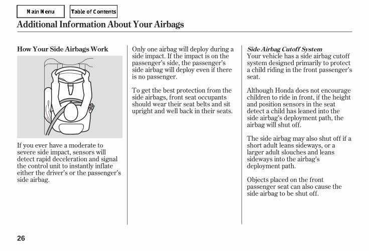
If you ever have a moderate tosevere side impact, sensors willdetect rapid deceleration and signalthe control unit to instantly inflateeither the driver’s or the passenger’sside airbag.
Only one airbag will deploy during aside impact. If the impact is on thepassenger’s side, the passenger’sside airbag will deploy even if thereis no passenger.
To get the best protection from theside airbags, front seat occupantsshould wear their seat belts and situpright and well back in their seats.
The side airbag may also shut off if ashort adult leans sideways, or alarger adult slouches and leanssideways into the airbag’sdeployment path.
Objects placed on the frontpassenger seat can also cause theside airbag to be shut off.
Your vehicle has a side airbag cutoffsystem designed primarily to protecta child riding in the front passenger’sseat.
Although Honda does not encouragechildren to ride in front, if the heightand position sensors in the seatdetect a child has leaned into theside airbag’s deployment path, theairbag will shut off.
Additional Information About Your Airbags
How Your Side Airbags Work Side Airbag Cutoff System
26
05/09/02 11:37:48 31SDR610 0029
If the side airbag off indicator comeson (see page ), have thepassenger sit upright. Once thepassenger is out of the airbag’sdeployment path, the system willturn the airbag back on, and theindicator will go out.
There will be some delay betweenthe moment the passenger movesinto or out of the airbag deploymentpath and when the indicator comeson or goes off.
A front seat passenger should notuse a cushion or other object as abackrest. It may prevent the cutoffsystem from working properly.
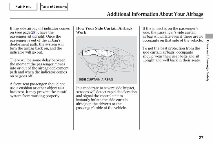
If the impact is on the passenger’sside, the passenger’s side curtainairbag will inflate even if there are nooccupants on that side of the vehicle.
To get the best protection from theside curtain airbags, occupantsshould wear their seat belts and situpright and well back in their seats.
In a moderate to severe side impact,sensors will detect rapid decelerationand signal the control unit toinstantly inflate the side curtainairbag on the driver’s or thepassenger’s side of the vehicle.
28
Additional Information About Your Airbags
How Your Side Curtain AirbagsWork
Driver
andP
assengerSafety
27
SIDE CURTAIN AIRBAG
05/09/02 11:37:55 31SDR610 0030
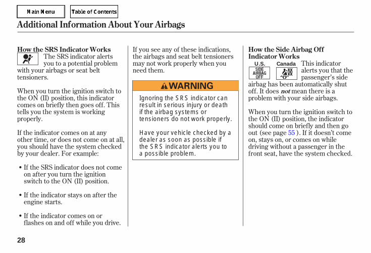
When you turn the ignition switch tothe ON (II) position, this indicatorcomes on briefly then goes off. Thistells you the system is workingproperly.
The SRS indicator alertsyou to a potential problem
with your airbags or seat belttensioners.
If you see any of these indications,the airbags and seat belt tensionersmay not work properly when youneed them.
This indicatoralerts you that thepassenger’s side
airbag has been automatically shutoff. It does mean there is aproblem with your side airbags.
If the indicator comes on orflashes on and off while you drive.
If the indicator stays on after theengine starts.
If the SRS indicator does not comeon after you turn the ignitionswitch to the ON (II) position.
If the indicator comes on at anyother time, or does not come on at all,you should have the system checkedby your dealer. For example:
When you turn the ignition switch tothe ON (II) position, the indicatorshould come on briefly and then goout (see page ). If it doesn’t comeon, stays on, or comes on whiledriving without a passenger in thefront seat, have the system checked.
55
Additional Information About Your Airbags
How the SRS Indicator Works How the Side Airbag OffIndicator Works
not
28
CanadaU.S.
Ignoring the SRS indicator canresult in serious injury or deathif the airbag systems ortensioners do not work properly.
Have your vehicle checked by adealer as soon as possible ifthe SRS indicator alerts you toa possible problem.
05/09/02 11:38:05 31SDR610 0031
Take your vehicle to anauthorized dealer as soon aspossible. If you ignore thisindication, your airbags may notoperate properly.
Even if yourairbags do not inflate, your dealershould inspect the driver’s seatposition sensor and the frontpassenger’s weight sensors tomake sure they are operatingproperly.
Your airbag systems are virtuallymaintenance free, and there are noparts you can safely service.However, you must have yourvehicle serviced if:
Any airbagthat has deployed must bereplaced along with the controlunit and other related parts. If afront airbag inflates, the seat belttensioners must also be replaced.
Do not try to remove or replaceany airbag by yourself. This mustbe done by your dealer or aknowledgeable body shop.
Additional Information About Your Airbags
The SRS indicator alerts you to aproblem.
If your vehicle has a moderate tosevere impact.
An airbag ever inflates.Airbag Service
Driver
andP
assengerSafety
29
05/09/02 11:38:11 31SDR610 0032
Together, airbags andseat belts provide the bestprotection.
Tampering could causethe airbags to deploy, possiblycausing very serious injury.
Improperly replacingor covering front seat-back coverscan prevent your side airbags frominflating during a side impact.
If water oranother liquid soaks into the seat-back, it can prevent the side airbagcutoff system from workingproperly.
Additional Safety PrecautionsDo not attempt to deactivate yourairbags.
Do not tamper with airbagcomponents or wiring for anyreason.
Do not cover or replace front seat-back covers without consultingyour dealer.
Do not expose the front passenger’sseat-back to liquid.
Additional Information About Your Airbags
30
05/09/02 11:38:16 31SDR610 0033
--
-
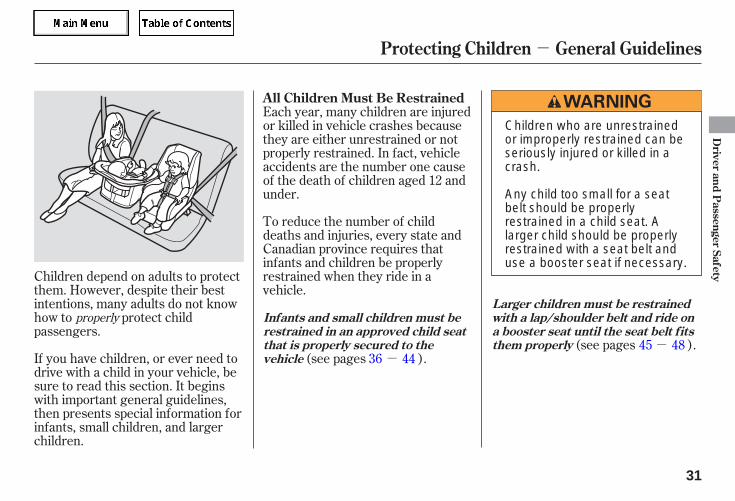
If you have children, or ever need todrive with a child in your vehicle, besure to read this section. It beginswith important general guidelines,then presents special information forinfants, small children, and largerchildren.
To reduce the number of childdeaths and injuries, every state andCanadian province requires thatinfants and children be properlyrestrained when they ride in avehicle.
(see pages ).(see pages ).
Children depend on adults to protectthem. However, despite their bestintentions, many adults do not knowhow to protect childpassengers.
Each year, many children are injuredor killed in vehicle crashes becausethey are either unrestrained or notproperly restrained. In fact, vehicleaccidents are the number one causeof the death of children aged 12 andunder.
36 4445 48
properly
All Children Must Be Restrained
Infants and small children must berestrained in an approved child seatthat is properly secured to thevehicle
Larger children must be restrainedwith a lap/shoulder belt and ride ona booster seat until the seat belt f itsthem properly
Protecting Children General Guidelines
Driver
andP
assengerSafety
31
Children who are unrestrainedor improperly restrained can beseriously injured or killed in acrash.
Any child too small for a seatbelt should be properlyrestrained in a child seat. Alarger child should be properlyrestrained with a seat belt anduse a booster seat if necessary.
05/09/02 11:38:24 31SDR610 0034
-
Front airbags have been designed tohelp protect adults in a moderate tosevere frontal collision. To do this,the passenger’s front airbag is quitelarge, and it can inflate with enoughforce to cause very serious injuries.
If the vehicle seat istoo far forward, or the child’s head isthrown forward during a collision, aninflating front airbag can strike thechild with enough force to kill orvery seriously injure a small child.
Whenever possible,larger children should sit in the backseat, on a booster seat if needed, andbe properly restrained with a seatbelt (see page for importantinformation about protecting largerchildren).
Ifthe airbag inflates, it can hit the backof the child seat with enough forceto kill or very seriously injure aninfant.
According to accident statistics,children of all ages and sizes aresafer when they are restrained in aback seat.
The National Highway Traffic SafetyAdministration and TransportCanada recommend that all childrenaged 12 and under be properlyrestrained in a back seat. Somestates have laws restricting wherechildren may ride.
Children who ride in the back areless likely to be injured by strikinginterior vehicle parts during acollision or hard braking. Also,children cannot be injured by aninflating front airbag when they ridein the back.
45
Small ChildrenPlacing a forward-facing child seat inthe front seat of a vehicle equippedwith a passenger’s front airbag canbe hazardous.
Larger ChildrenChildren who have outgrown childseats are also at risk of being injuredor killed by an inflating passenger’sfront airbag.
InfantsNever put a rear-facing child seat inthe front seat of a vehicle equippedwith a passenger’s front airbag.
All Children Should Sit in a BackSeat
The Passenger’s Front AirbagPoses Serious Risks
Protecting Children General Guidelines
32
05/09/02 11:38:32 31SDR610 0035
-
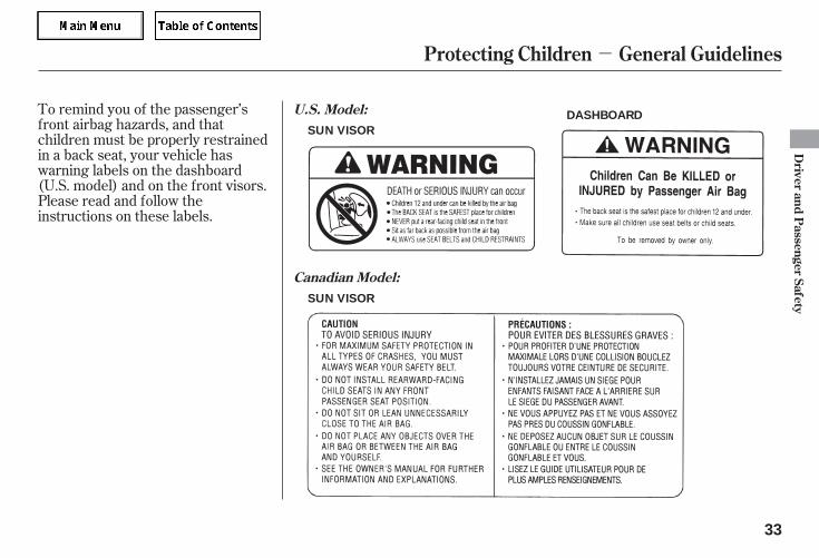
To remind you of the passenger’sfront airbag hazards, and thatchildren must be properly restrainedin a back seat, your vehicle haswarning labels on the dashboard(U.S. model) and on the front visors.Please read and follow theinstructions on these labels.
Protecting Children General Guidelines
U.S. Model:
Canadian Model:
Driver
andP
assengerSafety
33
SUN VISOR
SUN VISOR
DASHBOARD
05/09/02 11:38:46 31SDR610 0036
-
Many parents say they prefer to putan infant or small child in the frontpassenger seat so they can watch thechild, or because the child requiresattention.
Placing a child in the front seatexposes the child to hazards in afrontal collision, and paying closeattention to a child distracts thedriver from the important tasks ofdriving, placing both of you at risk.
Your vehicle has a back seat wherechildren can be properly restrained.If you ever have to carry a group ofchildren, and a child must ride infront:
Place the largest child in the frontseat, provided the child is largeenough to wear the lap/shoulderbelt properly (see page ).
Move the vehicle seat as far to therear as possible (see page ).
Have the child sit upright and wellback in the seat (see page ).
Make sure the seat belt is properlypositioned and secured (see page
).
If a child requires close physicalattention or frequent visualcontact, we strongly recommendthat another adult ride with thechild in a back seat. The back seatis far safer for a child than thefront.
16
13
45
17
If a Child Requires CloseAttention
If You Must Drive with SeveralChildren
Protecting Children General Guidelines
34
05/09/02 11:38:54 31SDR610 0037
-
During a crash, thebelt could press deep into the childand cause serious or fatal injuries.
If they do, theycould be very seriously injured in acrash.
This can prevent childrenfrom accidentally falling out (seepage ).
Leaving children withoutadult supervision is illegal in moststates and Canadian provinces,and can be very hazardous.
For example, infants and smallchildren left in a vehicle on a hotday can die from heatstroke. Achild left alone with the key in theignition switch can accidentally setthe vehicle in motion, possiblyinjuring themselves or others.
Childrenwho play in vehicles canaccidentally get trapped inside.Teach your children not to play inor around vehicles. Know how tooperate the emergency trunkopener and decide if your childrenshould be shown how to use thisfeature (see page ).
Even very youngchildren learn how to unlockvehicle doors, turn on the ignitionswitch, and open the trunk, whichcan lead to accidental injury ordeath.
If you are not wearing aseat belt in a crash, you could bethrown forward and crush thechild against the dashboard or aseat-back. If you are wearing aseat belt, the child can be tornfrom your arms and be seriouslyhurt or killed.
80
84
Additional Safety Precautions
Never put a seat belt over yourselfand a child.
Never let two children use thesame seat belt.
Use childproof door locks toprevent children from opening thedoors.
Do not leave children alone in avehicle.
Lock all doors and the trunk whenyour vehicle is not in use.
Keep vehicle keys and remotetransmitters out of the reach ofchildren.
Never hold an infant or child onyour lap.
Protecting Children General Guidelines
Driver
andP
assengerSafety
35
05/09/02 11:39:02 31SDR610 0038
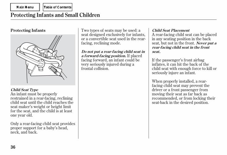
An infant must be properlyrestrained in a rear-facing, recliningchild seat until the child reaches theseat maker’s weight or height limitfor the seat, and the child is at leastone year old.
Only a rear-facing child seat providesproper support for a baby’s head,neck, and back.
Two types of seats may be used: aseat designed exclusively for infants,or a convertible seat used in the rear-facing, reclining mode.
If placedfacing forward, an infant could bevery seriously injured during afrontal collision.
A rear-facing child seat can be placedin any seating position in the backseat, but not in the front.
If the passenger’s front airbaginflates, it can hit the back of thechild seat with enough force to kill orseriously injure an infant.
When properly installed, a rear-facing child seat may prevent thedriver or a front passenger frommoving their seat as far back asrecommended, or from locking theirseat-back in the desired position.
Protecting Infants
Child Seat Type
Child Seat Placement
Do not put a rear-facing child seat ina forward-facing position.
Never put arear-facing child seat in the frontseat.
Protecting Infants and Small Children
36
05/09/02 11:39:10 31SDR610 0039
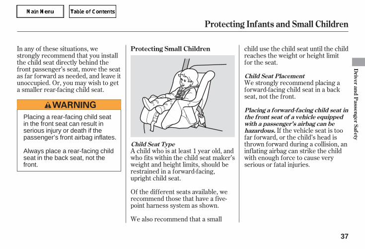
A child who is at least 1 year old, andwho fits within the child seat maker’sweight and height limits, should berestrained in a forward-facing,upright child seat.
Of the different seats available, werecommend those that have a five-point harness system as shown.
If the vehicle seat is toofar forward, or the child’s head isthrown forward during a collision, aninflating airbag can strike the childwith enough force to cause veryserious or fatal injuries.
We strongly recommend placing aforward-facing child seat in a backseat, not the front.
In any of these situations, westrongly recommend that you installthe child seat directly behind thefront passenger’s seat, move the seatas far forward as needed, and leave itunoccupied. Or, you may wish to geta smaller rear-facing child seat.
We also recommend that a small
child use the child seat until the childreaches the weight or height limitfor the seat.
Protecting Small Children
Child Seat Type
Placing a forward-facing child seat inthe front seat of a vehicle equippedwith a passenger’s airbag can behazardous.
Child Seat Placement
Protecting Infants and Small Children
Driver
andP
assengerSafety
37
Placing a rear-facing child seatin the front seat can result inserious injury or death if thepassenger’s front airbag inflates.
Always place a rear-facing childseat in the back seat, not thefront.
05/09/02 11:39:18 31SDR610 0040
Conventional child seats must besecured to a vehicle with a seat belt,whereas LATCH-compatible seatsare secured by attaching the seat tohardware built into the two outerseating positions in the back seat.
Since LATCH-compatible child seatsare easier to install and reduce thepossibility of improper installation,we recommend selecting this style.
We also recommend selecting aLATCH-compatible seat with a rigid,rather than a flexible, anchor (seepage ).
In seating positions and vehicles notequipped with LATCH, a LATCH-compatible child seat can be installedusing a seat belt.
If it is necessary to put a forward-facing child seat in the front, movethe vehicle seat as far to the rear aspossible, and be sure the child seat isfirmly secured to the vehicle and thechild is properly strapped in the seat. Whatever type of seat you choose, to
provide proper protection, a childseat should meet threerequirements:
Look for FMVSS213 or CMVSS 213 on the box.
Rear-facing for infants, forward-facing for small children.
When buying a child seat, you needto choose either a conventional childseat, or one designed for use withthe lower anchors and tethers forchildren (LATCH) system.
1.
2.
40
Selecting a Child Seat
The child seat should meet U.S. orCanadian Motor Vehicle SafetyStandard 213.
The child seat should be of theproper type and size to fit the child.
Protecting Infants and Small Children, Selecting a Child Seat
38
Placing a forward-facing childseat in the front seat can resultin serious injury or death if thefront airbag inflates.
If you must place a forward-facing child seat in front, movethe vehicle seat as far back aspossible, and properly restrainthe child.
05/09/02 11:39:26 31SDR610 0041
After selecting a proper child seatand a good place to install the seat,there are three main steps ininstalling the seat:
All child seats must besecured to the vehicle with the lappart of a lap/shoulder belt or withthe LATCH (lower anchors andtethers for children) system. Achild whose seat is not properlysecured to the vehicle can beendangered in a crash.
After installing a childseat, push and pull the seatforward and from side-to-side toverify that it is secure.
A child seat secured with a seat beltshould be installed as firmly aspossible. However, it does not needto be ‘‘rock solid.’’ Some side-to-side
movement can be expected andshould not reduce the child seat’seffectiveness.
If the child seat is not secure, tryinstalling it in a different seatingposition, or use a different style ofchild seat that can be firmly secured.
Before purchasing a conventionalchild seat, or using a previouslypurchased one, we recommend thatyou test the seat in the specificvehicle seating position or positionswhere the seat will be used.
Make sure the child is properlystrapped in the child seataccording to the child seat maker’sinstructions. A child who is notproperly secured in a child seatcan be seriously injured in a crash.
The following pages provideguidelines on how to properly installa child seat. A forward-facing childseat is used in all examples, but theinstructions are the same for rear-facing child seats.
3.
1.
2.
3.
Installing a Child Seat
Properly secure the child seat tothe vehicle.
Make sure the child seat is firmlysecured.
The child seat should fit thevehicle seating position (orpositions) where it will be used.
Secure the child in the child seat.
Selecting a Child Seat, Installing a Child Seat
Driver
andP
assengerSafety
39
05/09/02 11:39:35 31SDR610 0042
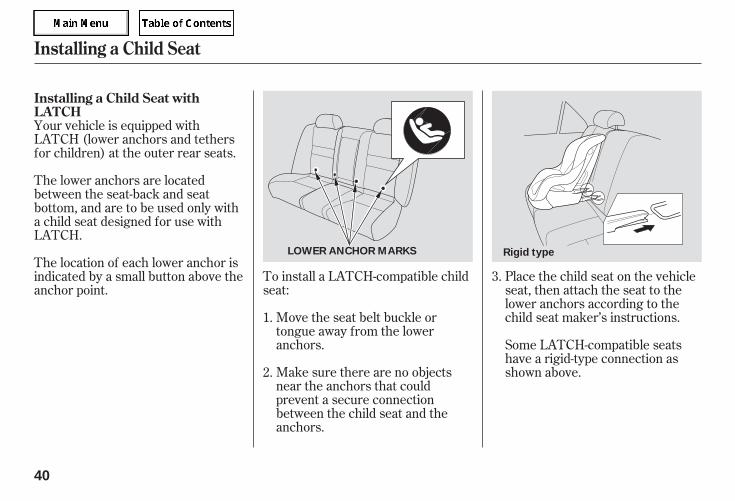
Make sure there are no objectsnear the anchors that couldprevent a secure connectionbetween the child seat and theanchors.
Move the seat belt buckle ortongue away from the loweranchors.
To install a LATCH-compatible childseat:
Place the child seat on the vehicleseat, then attach the seat to thelower anchors according to thechild seat maker’s instructions.
Some LATCH-compatible seatshave a rigid-type connection asshown above.
Your vehicle is equipped withLATCH (lower anchors and tethersfor children) at the outer rear seats.
The lower anchors are locatedbetween the seat-back and seatbottom, and are to be used only witha child seat designed for use withLATCH.
The location of each lower anchor isindicated by a small button above theanchor point.
1.
2.
3.
Installing a Child Seat withLATCH
Installing a Child Seat
40
Rigid typeLOWER ANCHOR MARKS
05/09/02 11:39:44 31SDR610 0043
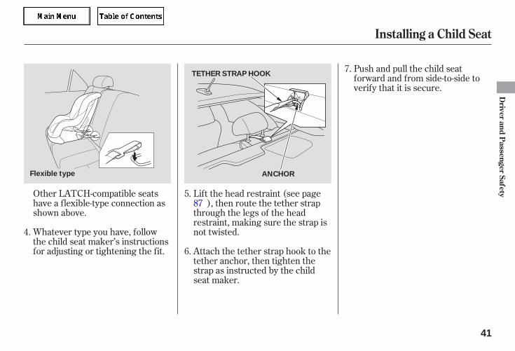
Other LATCH-compatible seatshave a flexible-type connection asshown above.
Whatever type you have, followthe child seat maker’s instructionsfor adjusting or tightening the fit.
Push and pull the child seatforward and from side-to-side toverify that it is secure.
Lift the head restraint (see page), then route the tether strap
through the legs of the headrestraint, making sure the strap isnot twisted.
Attach the tether strap hook to thetether anchor, then tighten thestrap as instructed by the childseat maker.
4.
5.
6.
7.
87
Installing a Child Seat
Driver
andP
assengerSafety
41
TETHER STRAP HOOK
Flexible type ANCHOR
05/09/02 11:39:50 31SDR610 0044
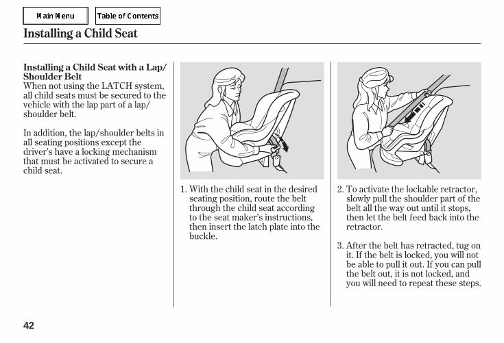
When not using the LATCH system,all child seats must be secured to thevehicle with the lap part of a lap/shoulder belt.
With the child seat in the desiredseating position, route the beltthrough the child seat accordingto the seat maker’s instructions,then insert the latch plate into thebuckle.
To activate the lockable retractor,slowly pull the shoulder part of thebelt all the way out until it stops,then let the belt feed back into theretractor.
After the belt has retracted, tug onit. If the belt is locked, you will notbe able to pull it out. If you can pullthe belt out, it is not locked, andyou will need to repeat these steps.
In addition, the lap/shoulder belts inall seating positions except thedriver’s have a locking mechanismthat must be activated to secure achild seat.
1. 2.
3.
Installing a Child Seat with a Lap/Shoulder Belt
Installing a Child Seat
42
05/09/02 11:39:57 31SDR610 0045
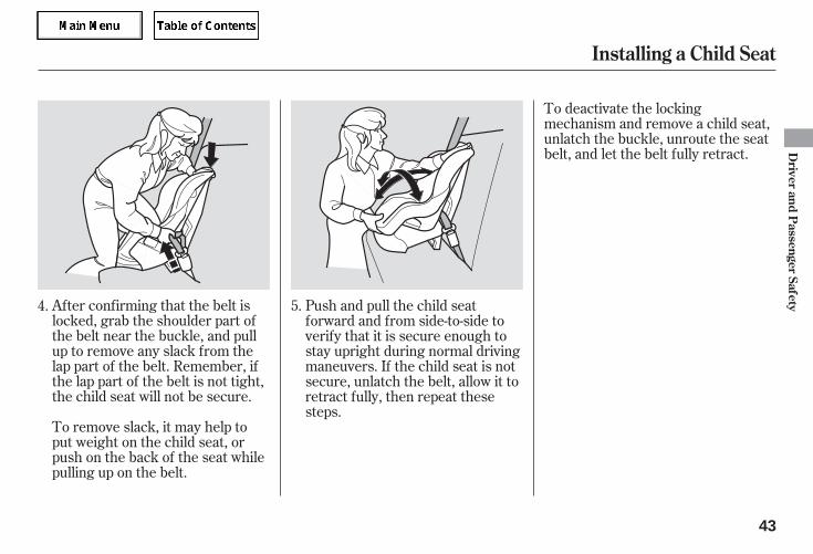
After confirming that the belt islocked, grab the shoulder part ofthe belt near the buckle, and pullup to remove any slack from thelap part of the belt. Remember, ifthe lap part of the belt is not tight,the child seat will not be secure.
To deactivate the lockingmechanism and remove a child seat,unlatch the buckle, unroute the seatbelt, and let the belt fully retract.
Push and pull the child seatforward and from side-to-side toverify that it is secure enough tostay upright during normal drivingmaneuvers. If the child seat is notsecure, unlatch the belt, allow it toretract fully, then repeat thesesteps.
To remove slack, it may help toput weight on the child seat, orpush on the back of the seat whilepulling up on the belt.
4. 5.
Installing a Child Seat
Driver
andP
assengerSafety
43
05/09/02 11:40:03 31SDR610 0046
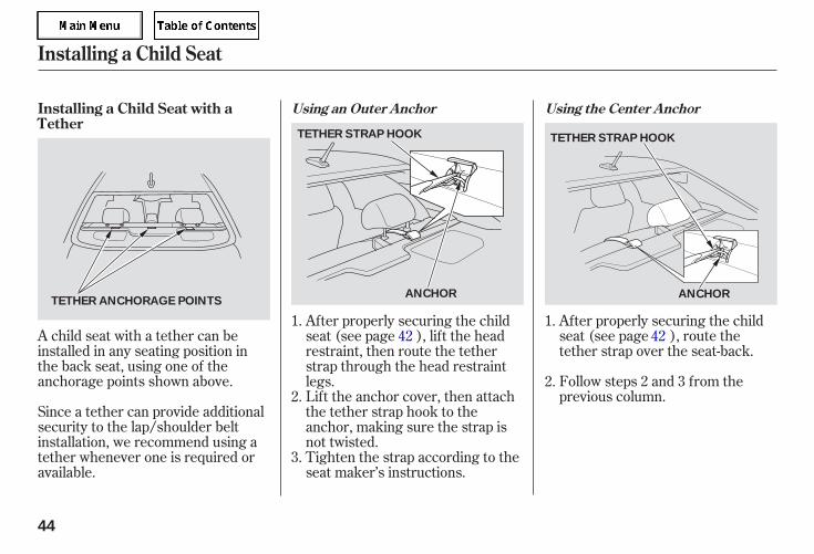
A child seat with a tether can beinstalled in any seating position inthe back seat, using one of theanchorage points shown above.
Since a tether can provide additionalsecurity to the lap/shoulder beltinstallation, we recommend using atether whenever one is required oravailable.
Tighten the strap according to theseat maker’s instructions.
After properly securing the childseat (see page ), route thetether strap over the seat-back.
Follow steps 2 and 3 from theprevious column.Lift the anchor cover, then attach
the tether strap hook to theanchor, making sure the strap isnot twisted.
After properly securing the childseat (see page ), lift the headrestraint, then route the tetherstrap through the head restraintlegs.
1.
2.
3.
1.
2.
4242
Installing a Child Seat with aTether
Using an Outer Anchor Using the Center Anchor
Installing a Child Seat
44
TETHER STRAP HOOK
TETHER ANCHORAGE POINTS
TETHER STRAP HOOK
ANCHOR ANCHOR
05/09/02 11:40:13 31SDR610 0047
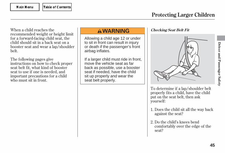
To determine if a lap/shoulder beltproperly fits a child, have the childput on the seat belt, then askyourself:
When a child reaches therecommended weight or height limitfor a forward-facing child seat, thechild should sit in a back seat on abooster seat and wear a lap/shoulderbelt.
Does the child sit all the way backagainst the seat?
Do the child’s knees bendcomfortably over the edge of theseat?
The following pages giveinstructions on how to check properseat belt fit, what kind of boosterseat to use if one is needed, andimportant precautions for a childwho must sit in front.
1.
2.
Checking Seat Belt Fit
Protecting Larger Children
Driver
andP
assengerSafety
45
Allowing a child age 12 or underto sit in front can result in injuryor death if the passenger’s frontairbag inflates.
If a larger child must ride in front,move the vehicle seat as farback as possible, use a boosterseat if needed, have the childsit up properly and wear theseat belt properly.
05/09/02 11:40:20 31SDR610 0048
Does the shoulder belt crossbetween the child’s neck and arm?
Is the lap part of the belt as low aspossible, touching the child’sthighs?
Will the child be able to stayseated like this for the whole trip?
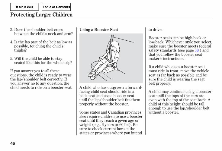
If you answer yes to all thesequestions, the child is ready to wearthe lap/shoulder belt correctly. Ifyou answer no to any question, thechild needs to ride on a booster seat. A child who has outgrown a forward-
facing child seat should ride in aback seat and use a booster seatuntil the lap/shoulder belt fits themproperly without the booster.
Some states and Canadian provincesalso require children to use a boosterseat until they reach a given age orweight (e.g., 6 years or 60 lbs). Besure to check current laws in thestates or provinces where you intend
to drive.
Booster seats can be high-back orlow-back. Whichever style you select,make sure the booster meets federalsafety standards (see page ) andthat you follow the booster seatmaker’s instructions.
If a child who uses a booster seatmust ride in front, move the vehicleseat as far back as possible and besure the child is wearing the seatbelt properly.
A child may continue using a boosterseat until the tops of the ears areeven with the top of the seat-back. Achild of this height should be tallenough to use the lap/shoulder beltwithout a booster.
4.
5.
3.
38
Using a Booster Seat
Protecting Larger Children
46
05/09/02 11:40:28 31SDR610 0049
If you decide that a child can safelyride up front, be sure to:
Carefully read the owner’s manual,and make sure you understand allseat belt instructions and all safetyinformation.
Move the vehicle seat to the rear-most position.
Have the child sit up straight, backagainst the seat, and feet on ornear the floor.
Check that the child’s seat belt isproperly and securely positioned.
Supervise the child. Even maturechildren sometimes need to bereminded to fasten the seat beltsor sit properly.
Of course, children vary widely. Andwhile age may be one indicator ofwhen a child can safely ride in front,there are other important factors youshould consider.
If the passenger’s front airbaginflates in a moderate to severefrontal collision, the airbag can causeserious injuries to a child who isunrestrained, improperly restrained,sitting too close to the airbag, or outof position.
A side airbag also poses risks. If anypart of a larger child’s body is in thepath of a deploying side airbag, thechild could receive possibly seriousinjuries.
Physically, a child must be largeenough for the lap/shoulder belt toproperly fit (see page ). If the seatbelt does not fit properly, with orwithout the child sitting on a boosterseat, the child should not sit in front.
To safely ride in front, a child mustbe able to follow the rules, includingsitting properly, and wearing the seatbelt properly throughout a ride.
The National Highway Traffic SafetyAdministration and TransportCanada recommend that all childrenaged 12 and under be properlyrestrained in a back seat.
45
Physical Size
Maturity
When Can a Larger Child Sit inFront
Protecting Larger Children
Driver
andP
assengerSafety
47
05/09/02 11:40:38 31SDR610 0050
This could resultin serious neck injuries during acrash.
Devices intended toimprove a child’s comfort orreposition the shoulder part of aseat belt can make the belt lesseffective and increase the chanceof serious injury in a crash.
This couldcause very serious injuries duringa crash. It also increases thechance that the child will slideunder the belt in a crash and beinjured.
If they do, theycould be very seriously injured in acrash.
Do not let a child wear a seat beltacross the neck.
Do not put any accessories on aseat belt.
Do not let a child put the shoulderpart of a seat belt behind the backor under the arm.
Two children should never use thesame seat belt.
Additional Safety Precautions
Protecting Larger Children
48
05/09/02 11:40:43 31SDR610 0051
Your vehicle’s exhaust containscarbon monoxide gas. You shouldhave no problem with carbonmonoxide entering the vehicle innormal driving if you maintain yourvehicle properly.
High levels of carbon monoxide cancollect rapidly in enclosed areas,such as a garage. Do not run theengine with the garage door closed.Even with the door open, run theengine only long enough to move thevehicle out of the garage.
Have the exhaust system inspectedfor leaks whenever:
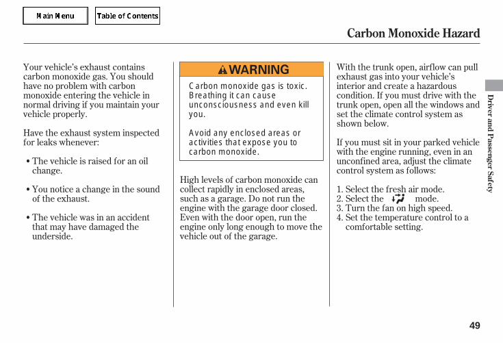
With the trunk open, airflow can pullexhaust gas into your vehicle’sinterior and create a hazardouscondition. If you must drive with thetrunk open, open all the windows andset the climate control system asshown below.
If you must sit in your parked vehiclewith the engine running, even in anunconfined area, adjust the climatecontrol system as follows:
Select the fresh air mode.Select the mode.Turn the fan on high speed.Set the temperature control to acomfortable setting.
The vehicle is raised for an oilchange.
You notice a change in the soundof the exhaust.
The vehicle was in an accidentthat may have damaged theunderside.
1.2.3.4.
Carbon Monoxide Hazard
Driver
andP
assengerSafety
49
Carbon monoxide gas is toxic.Breathing it can causeunconsciousness and even killyou.
Avoid any enclosed areas oractivities that expose you tocarbon monoxide.
05/09/02 11:40:51 31SDR610 0052
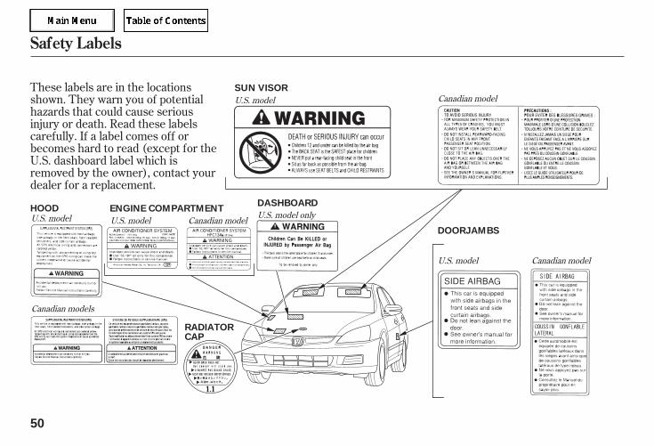
These labels are in the locationsshown. They warn you of potentialhazards that could cause seriousinjury or death. Read these labelscarefully. If a label comes off orbecomes hard to read (except for theU.S. dashboard label which isremoved by the owner), contact yourdealer for a replacement.
Canadian models
U.S. model
U.S. model
U.S. model Canadian model
Canadian model
U.S. modelU.S. model only
Canadian model
Safety Labels
50
SUN VISOR
HOOD
DOORJAMBS
RADIATORCAP
ENGINE COMPARTMENTDASHBOARD
05/09/22 10:46:29 31SDR610 0053
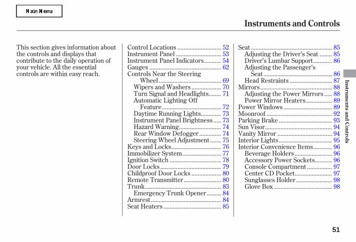
This section gives information aboutthe controls and displays thatcontribute to the daily operation ofyour vehicle. All the essentialcontrols are within easy reach.
...........................Control Locations . 52............................Instrument Panel . 53
..........Instrument Panel Indicators . 54.............................................Gauges . 62
Controls Near the Steering.......................................Wheel . 69
..................Wipers and Washers . 70.......Turn Signal and Headlights . 71
Automatic Lighting Off.....................................Feature . 72
............Daytime Running Lights . 73....Instrument Panel Brightness . 73
..........................Hazard Warning . 74.............Rear Window Defogger . 74
......Steering Wheel Adjustment . 75...............................Keys and Locks . 76
........................Immobilizer System . 77................................Ignition Switch . 78
......................................Door Locks . 79..................Childproof Door Locks . 80
.......................Remote Transmitter . 80................................................Trunk . 83
........Emergency Trunk Opener . 84............................................Armrest . 84
....................................Seat Heaters . 85
...................................................Seat . 85.......Adjusting the Driver’s Seat . 85
...........Driver’s Lumbar Support . 86Adjusting the Passenger’s
...........................................Seat . 86..........................Head Restraints . 87
.............................................Mirrors . 88....Adjusting the Power Mirrors . 88
................Power Mirror Heaters . 89..............................Power Windows . 89
.........................................Moonroof . 92.................................Parking Brake . 93
..........................................Sun Visor . 94..................................Vanity Mirror . 94.................................Interior Lights . 95
...........Interior Convenience Items . 96.......................Beverage Holders . 96
..........Accessory Power Sockets . 96...............Console Compartment . 97
.......................Center CD Pocket . 97......................Sunglasses Holder . 98
....................................Glove Box . 98
Instruments and Controls
Instruments
andC
ontrols
51
05/09/02 11:41:28 31SDR610 0054
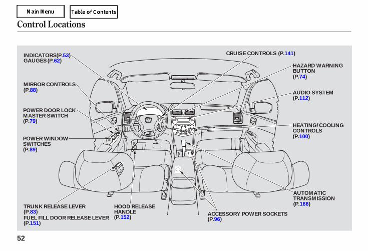
Control Locations
52
POWER WINDOWSWITCHES
MIRROR CONTROLS
ACCESSORY POWER SOCKETS
AUDIO SYSTEM
HEATING/COOLINGCONTROLS
HAZARD WARNINGBUTTON
CRUISE CONTROLS
TRUNK RELEASE LEVER HOOD RELEASEHANDLE
INDICATORSGAUGES
FUEL FILL DOOR RELEASE LEVER
(P.53)
(P.100)
(P.112)
AUTOMATICTRANSMISSION
(P.88)
POWER DOOR LOCKMASTER SWITCH(P.79)
(P.83)
(P.151)(P.152) (P.96)
(P.166)
(P.74)
(P.141)
(P.89)
(P.62)
05/09/02 11:41:33 31SDR610 0055
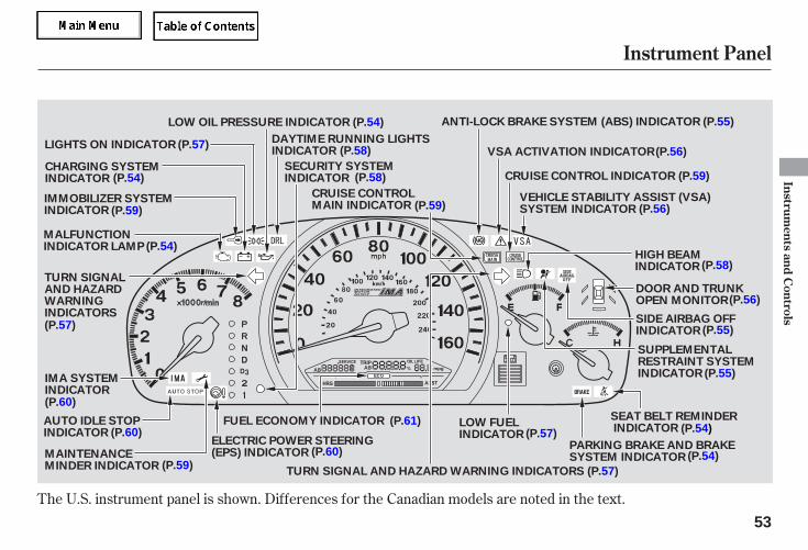
The U.S. instrument panel is shown. Differences for the Canadian models are noted in the text.
Instrument Panel
Instruments
andC
ontrols
53
MALFUNCTIONINDICATOR LAMP
SUPPLEMENTALRESTRAINT SYSTEMINDICATOR
DOOR AND TRUNKOPEN MONITOR
LIGHTS ON INDICATOR
SIDE AIRBAG OFFINDICATOR
CRUISE CONTROL INDICATOR
LOW OIL PRESSURE INDICATOR (P.54)
(P.56)
(P.59)
(P.56)
(P.55)
(P.55)
(P.54)
(P.58)
(P.60)
IMA SYSTEMINDICATOR(P.60)
(P.60)
(P.57)
(P.54)
(P.54)
(P.58)
CRUISE CONTROLMAIN INDICATOR (P.59)
FUEL ECONOMY INDICATOR SEAT BELT REMINDERINDICATOR
(P.61)
VSA ACTIVATION INDICATOR
(P.57)
(P.59)
HIGH BEAMINDICATOR
ANTI-LOCK BRAKE SYSTEM (ABS) INDICATOR (P.55)
DAYTIME RUNNING LIGHTSINDICATOR (P.58)
SECURITY SYSTEMINDICATOR
CHARGING SYSTEMINDICATOR
IMMOBILIZER SYSTEMINDICATOR
TURN SIGNALAND HAZARDWARNINGINDICATORS
AUTO IDLE STOPINDICATOR (P.54)
PARKING BRAKE AND BRAKESYSTEM INDICATOR
(P.57)LOW FUELINDICATOR
TURN SIGNAL AND HAZARD WARNING INDICATORS
ELECTRIC POWER STEERING(EPS) INDICATOR
(P.57)
MAINTENANCEMINDER INDICATOR (P.59)
VEHICLE STABILITY ASSIST (VSA)SYSTEM INDICATOR (P.56)
05/09/02 11:41:42 31SDR610 0056
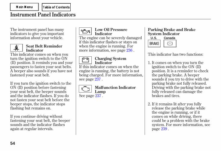
The instrument panel has manyindicators to give you importantinformation about your vehicle.
If this indicator comes on when theengine is running, the battery is notbeing charged. For more information,see page .
See page .
This indicator has two functions:This indicator comes on when youturn the ignition switch to the ON(II) position. It reminds you and yourpassengers to fasten your seat belts.A beeper also sounds if you have notfastened your seat belt.
If you continue driving withoutfastening your seat belt, the beepersounds and the indicator flashesagain at regular intervals.
It comes on when you turn theignition switch to the ON (II)position. It is a reminder to checkthe parking brake. A beepersounds if you try to drive with theparking brake not fully released.Driving with the parking brake notfully released can damage thebrakes and tires.
The engine can be severely damagedif this indicator flashes or stays onwhen the engine is running. Formore information, see page .
If you turn the ignition switch to theON (II) position before fasteningyour seat belt, the beeper soundsand the indicator flashes. If you donot fasten your seat belt before thebeeper stops, the indicator stopsflashing but remains on.
If it remains lit after you fullyrelease the parking brake whilethe engine is running, or if itcomes on while driving, therecould be a problem with the brakesystem. For more information, seepage .
1.
2.
236
237
237
239
Low Oil PressureIndicator
Charging SystemIndicator
Malfunction IndicatorLamp
Seat Belt ReminderIndicator
Parking Brake and BrakeSystem Indicator
Instrument Panel Indicators
54
U.S. Canada
05/09/02 11:41:53 31SDR610 0057
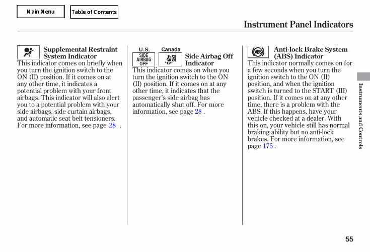
This indicator normally comes on fora few seconds when you turn theignition switch to the ON (II)position, and when the ignitionswitch is turned to the START (III)position. If it comes on at any othertime, there is a problem with theABS. If this happens, have yourvehicle checked at a dealer. Withthis on, your vehicle still has normalbraking ability but no anti-lockbrakes. For more information, seepage .
This indicator comes on when youturn the ignition switch to the ON(II) position. If it comes on at anyother time, it indicates that thepassenger’s side airbag hasautomatically shut off. For moreinformation, see page .
This indicator comes on briefly whenyou turn the ignition switch to theON (II) position. If it comes on atany other time, it indicates apotential problem with your frontairbags. This indicator will also alertyou to a potential problem with yourside airbags, side curtain airbags,and automatic seat belt tensioners.For more information, see page .28
28
175
Supplemental RestraintSystem Indicator
Anti-lock Brake System(ABS) IndicatorSide Airbag Off
Indicator
Instrument Panel Indicators
Instruments
andC
ontrols
55
U.S. Canada
05/09/02 11:42:00 31SDR610 0058
This indicator normally comes on fora few seconds when you turn theignition switch to the ON (II)position. For more information, seepage .
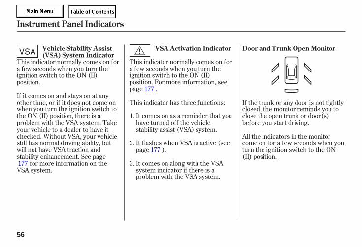
This indicator has three functions:
It comes on as a reminder that youhave turned off the vehiclestability assist (VSA) system.
It flashes when VSA is active (seepage ).
It comes on along with the VSAsystem indicator if there is aproblem with the VSA system.
This indicator normally comes on fora few seconds when you turn theignition switch to the ON (II)position.
If it comes on and stays on at anyother time, or if it does not come onwhen you turn the ignition switch tothe ON (II) position, there is aproblem with the VSA system. Takeyour vehicle to a dealer to have itchecked. Without VSA, your vehiclestill has normal driving ability, butwill not have VSA traction andstability enhancement. See page
for more information on theVSA system.
If the trunk or any door is not tightlyclosed, the monitor reminds you toclose the open trunk or door(s)before you start driving.
All the indicators in the monitorcome on for a few seconds when youturn the ignition switch to the ON(II) position.
1.
2.
3.177
177
177
Door and Trunk Open MonitorVSA Activation IndicatorVehicle Stability Assist(VSA) System Indicator
Instrument Panel Indicators
56
05/09/02 11:42:11 31SDR610 0059
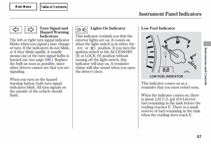
This indicator comes on as areminder that you must refuel soon.
The left or right turn signal indicatorblinks when you signal a lane changeor turn. If the indicators do not blink,or if they blink rapidly, it usuallymeans one of the turn signal bulbs isburned out (see page ). Replacethe bulb as soon as possible, sinceother drivers cannot see that you aresignaling.
When you turn on the hazardwarning button, both turn signalindicators blink. All turn signals onthe outside of the vehicle shouldflash.
This indicator reminds you that theexterior lights are on. It comes onwhen the light switch is in either the
or position. If you turn theignition switch to the ACCESSORY(I) or LOCK (0) position withoutturning off the light switch, thisindicator will stay on. A reminderchime will also sound when you openthe driver’s door.
When the indicator comes on, thereis about 2.62 U.S. gal (9.9 Liter)offuel remaining in the tank before thereading reaches E. There is a smallreserve of fuel remaining in the tankwhen the reading does reach E.
209
Turn Signal andHazard WarningIndicators
Lights On Indicator Low Fuel Indicator
Instrument Panel Indicators
Instruments
andC
ontrols
57
LOW FUEL INDICATOR
05/09/02 11:42:18 31SDR610 0060
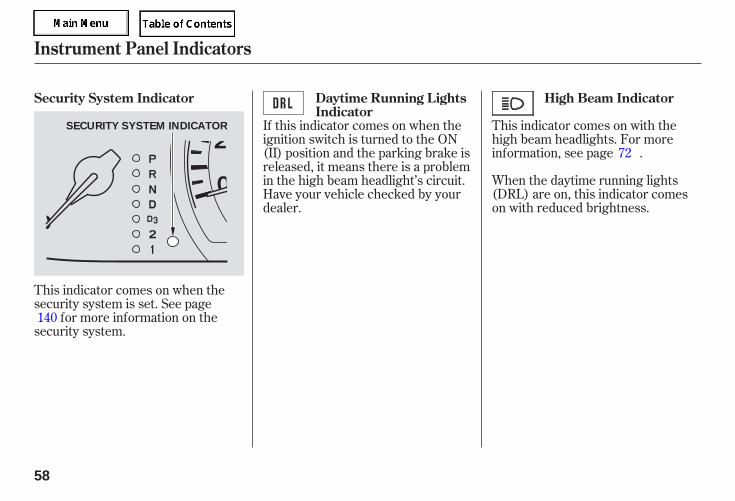
This indicator comes on when thesecurity system is set. See page
for more information on thesecurity system.
This indicator comes on with thehigh beam headlights. For moreinformation, see page .
When the daytime running lights(DRL) are on, this indicator comeson with reduced brightness.
If this indicator comes on when theignition switch is turned to the ON(II) position and the parking brake isreleased, it means there is a problemin the high beam headlight’s circuit.Have your vehicle checked by yourdealer.
140
72
Security System Indicator High Beam IndicatorDaytime Running LightsIndicator
Instrument Panel Indicators
58
SECURITY SYSTEM INDICATOR
05/09/02 11:42:24 31SDR610 0061
This indicator comes on when youturn on the cruise control masterbutton (see page ).
This indicator comes on when youset the cruise control. See page
for information on operating thecruise control.
This indicator comes on for a fewseconds when you turn the ignitionswitch to the ON (II) position. It willgo off if you have inserted aproperly-coded ignition key. If it isnot a properly-coded key, theindicator will blink and the enginewill not start (see page ).
This indicator also blinks severaltimes when you turn the ignitionswitch from the ON (II) position tothe ACCESSORY (I) or LOCK (0)position.
This indicator comes on when thewasher fluid level is low. Add washerfluid when you see this indicatorcome on (see page ).
This indicator reminds you that it istime to take your vehicle in forscheduled maintenance. Themaintenance main items and subitems will be displayed in theinformation display. See page formore information on themaintenance minder.
This indicator goes off when yourdealer resets it after completing therequired maintenance service.
141
187
77
200
141
Canadian model only
Cruise Control Indicator
Cruise Control MainIndicator
Immobilizer SystemIndicator
Washer Level Indicator
Maintenance MinderIndicator
Instrument Panel Indicators
Instruments
andC
ontrols
59
05/09/02 11:42:36 31SDR610 0062
This indicator normally comes on fora few seconds when you turn theignition switch to the ON (II)position. If it comes on at any othertime, it indicates a problem in theintegrated motor assist (IMA)system. With the IMA indicator on,the vehicle may not accelerate as itnormally does. Have the vehiclechecked by the dealer as soon aspossible.
See page .
If the power steering systemoverheats while driving, the assistingpower is reduced and steering mayfeel slightly harder.
If you drive with the systemoverheated continuously orrepeatedly, this can damage thepower steering system.
This indicator normally comes onwhen you turn the ignition switch tothe ON (II) position and goes offafter the engine starts. If it comes onat any other time, there is a problemin the electric power steering system.If this happens, stop the vehicle in asafe place, and turn off the engine.Reset the system by restarting theengine. The indicator will not turnoff immediately. If it does not go offafter driving a short distance, orcomes back on again while driving,take the vehicle to your dealer tohave it checked. With the indicatoron, the EPS may be off, making thevehicle harder to steer.
172
Instrument Panel Indicators
Electric Power Steering(EPS) Indicator
IMA System Indicator
Auto Idle Stop Indicator
60
05/09/02 11:42:44 31SDR610 0063
While the engine is operating in itsmost economical range, thisindicator may come on and stay on.
If the vehicle on board diagnosticsystem continues to detect aproblem, the Malfunction IndicatorLamp (MIL) will illuminate. If theMIL does not go off, have yourdealer inspect the vehicle. For moreinformation, see page .
If your fuel cap is loose or missing, a‘‘CHECK FUEL CAP’’ message willappear in the information display. Assoon as it is safely possible, turn theengine off and check that the fuelcap is installed. If it is, loosen the capand tighten it to at least 1 click.Although you can use the Select/Reset knob to cycle the fuel capwarning off of the display, it will bedisplayed again each time the engineis started. It will take several days ofnormal driving for the vehicle to turnthe warning off.
237
Fuel Economy IndicatorCheck Fuel Cap Display
Instrument Panel Indicators
Instruments
andC
ontrols
61
05/09/02 11:42:49 31SDR610 0064
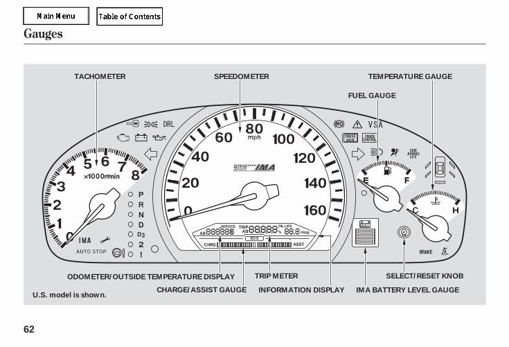
Gauges
62
SELECT/RESET KNOBTRIP METER
U.S. model is shown.
TEMPERATURE GAUGE
FUEL GAUGE
SPEEDOMETERTACHOMETER
CHARGE/ASSIST GAUGE IMA BATTERY LEVEL GAUGEINFORMATION DISPLAY
ODOMETER/OUTSIDE TEMPERATURE DISPLAY
05/09/02 11:42:53 31SDR610 0065
This display shows the outsidetemperature in Fahrenheit (U.S.models) or Centigrade (Canadianmodels). To see the outsidetemperature, press and release theSelect/Reset knob until thetemperature is displayed.
The temperature sensor is in thefront bumper. Therefore, thetemperature reading can be affectedby heat reflection from the roadsurface, engine heat, and theexhaust from surrounding traffic.This can cause an incorrecttemperature reading when yourspeed is under 19 mph (30 km/h).
The sensor delays the display updateuntil it reaches the correct outsidetemperature. This may take severalminutes.
The odometer shows the totaldistance your vehicle has beendriven. It measures miles in U.S.models and kilometers in Canadianmodels. It is illegal under U.S.federal law and Canadian provincialregulations to disconnect, reset, oralter the odometer with the intent tochange the number of miles orkilometers indicated.
The information display providesvarious information; odometer,outside temperature, trip meter, tripmileage, engine oil life, andmaintenance service items. Toswitch the display, press the Select/Reset knob repeatedly. When youturn the ignition switch to the ON(II) position, what you last selected isshown in the information display.
Gauges
Outside Temperature DisplayOdometer
Instruments
andC
ontrols
63
05/09/02 11:42:58 31SDR610 0066
± ±
- - - -- - - -
This meter shows the number ofmiles (U.S.) or kilometers (Canada)driven since you last reset it.
There are two trip meters: Trip Aand Trip B. Switch between thesedisplays and the odometer/outsidetemperature display by pressing theSelect/Reset knob repeatedly. Eachtrip meter works independently, soyou can keep track of two differentdistances.
If the outside temperature isincorrectly displayed, you can adjustit up to 5°F ( 3°C) warmer orcooler.
NOTE: The temperature must bestabilized before doing thisprocedure.
Select the outside temperaturedisplay, then press the Select/Resetknob for 10 seconds. The followingsequences appear, 1 second at atime: 0, 1, 2, 3, 4, 5, 5, 4, 3, 2,
1, 0, 1 (0, 1, 2, 3, 3, 2, 1, 0, 1).
When the temperature reaches thedesired value, release the Select/Reset knob. You should see the newoutside temperature displayed.
In certain weather conditions,temperature readings near freezing(32°F, 0°C) could mean that ice isforming on the road surface.
When you turn the ignition switch tothe ON (II) position, what you lastselected is displayed.
To reset a trip meter, display it, andthen press and hold the Select/Resetknob until the number resets to ‘‘0.0’’.
Trip Meter
Gauges
64
05/09/02 11:43:05 31SDR610 0067
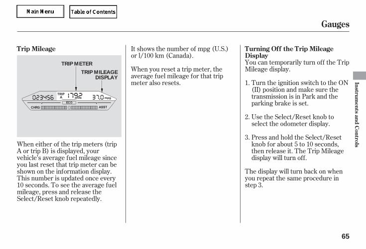
The display will turn back on whenyou repeat the same procedure instep 3.
You can temporarily turn off the TripMileage display.
Turn the ignition switch to the ON(II) position and make sure thetransmission is in Park and theparking brake is set.
When either of the trip meters (tripA or trip B) is displayed, yourvehicle’s average fuel mileage sinceyou last reset that trip meter can beshown on the information display.This number is updated once every10 seconds. To see the average fuelmileage, press and release theSelect/Reset knob repeatedly.
Use the Select/Reset knob toselect the odometer display.
Press and hold the Select/Resetknob for about 5 to 10 seconds,then release it. The Trip Mileagedisplay will turn off.
When you reset a trip meter, theaverage fuel mileage for that tripmeter also resets.
It shows the number of mpg (U.S.)or l/100 km (Canada).
1.
2.
3.
Trip Mileage Turning Off the Trip MileageDisplay
Gauges
Instruments
andC
ontrols
65
TRIP METER
TRIP MILEAGEDISPLAY
05/09/02 11:43:13 31SDR610 0068
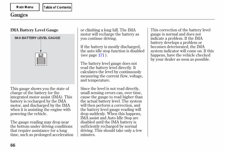
The battery level gauge does notread the battery level directly. Itcalculates the level by continuouslymeasuring the current flow, voltage,and temperature.
Since the level is not read directly,small sensing errors can, over time,cause the gauge to read higher thanthe actual battery level. The systemwill then perform a correction, andthe battery level gauge reading willdrop suddenly. When this happens,IMA assist and Auto Idle Stop aredisabled until the IMA battery issufficiently recharged by normaldriving. This should take only a fewminutes.
This correction of the battery levelgauge is normal and does notindicate a problem. If the IMAbattery develops a problem orbecomes deteriorated, the IMAsystem indicator will come on. If thishappens, have the vehicle checkedby your dealer as soon as possible.
If the battery is mostly discharged,the auto idle stop function is disabled(see page ).
This gauge shows you the state ofcharge of the battery for theintegrated motor assist (IMA). Thisbattery is recharged by the IMAmotor, and discharged by the IMAwhen it is assisting the engine withpowering the vehicle.
The gauge reading may drop nearthe bottom under driving conditionsthat require assistance for a longtime, such as prolonged acceleration
or climbing a long hill. The IMAmotor will recharge the battery asyou continue driving.
171
IMA Battery Level Gauge
Gauges
66
IMA BATTERY LEVEL GAUGE
05/09/02 11:43:20 31SDR610 0069
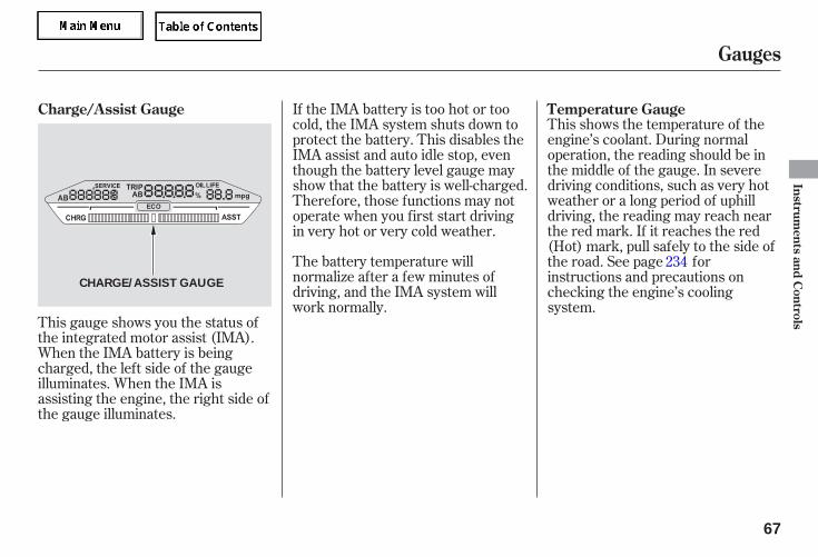
The battery temperature willnormalize after a few minutes ofdriving, and the IMA system willwork normally.
This gauge shows you the status ofthe integrated motor assist (IMA).When the IMA battery is beingcharged, the left side of the gaugeilluminates. When the IMA isassisting the engine, the right side ofthe gauge illuminates.
This shows the temperature of theengine’s coolant. During normaloperation, the reading should be inthe middle of the gauge. In severedriving conditions, such as very hotweather or a long period of uphilldriving, the reading may reach nearthe red mark. If it reaches the red(Hot) mark, pull safely to the side ofthe road. See page forinstructions and precautions onchecking the engine’s coolingsystem.
If the IMA battery is too hot or toocold, the IMA system shuts down toprotect the battery. This disables theIMA assist and auto idle stop, eventhough the battery level gauge mayshow that the battery is well-charged.Therefore, those functions may notoperate when you first start drivingin very hot or very cold weather.
234
Charge/Assist Gauge Temperature Gauge
Gauges
Instruments
andC
ontrols
67
CHARGE/ASSIST GAUGE
05/09/02 11:43:26 31SDR610 0070
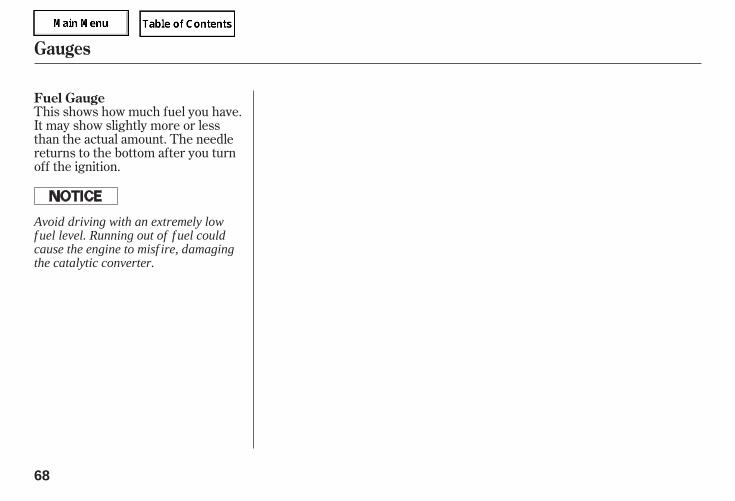
This shows how much fuel you have.It may show slightly more or lessthan the actual amount. The needlereturns to the bottom after you turnoff the ignition.
Fuel Gauge
Gauges
68
Avoid driving with an extremely lowf uel level. Running out of f uel couldcause the engine to misf ire, damagingthe catalytic converter.
05/09/02 11:43:30 31SDR610 0071
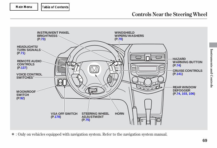
*
* Only on vehicles equipped with navigation system. Refer to the navigation system manual.:
Controls Near the Steering Wheel
Instruments
andC
ontrols
69
WINDSHIELDWIPERS/WASHERS
INSTRUMENT PANELBRIGHTNESS
VOICE CONTROLSWITCHES
HEADLIGHTS/TURN SIGNALS
REMOTE AUDIOCONTROLS
HORNSTEERING WHEELADJUSTMENT
CRUISE CONTROLS
REAR WINDOWDEFOGGER
HAZARDWARNING BUTTON
(P.73)
(P.71)
(P.137)
(P.178)(P.75)
(P.74, 103, 106)
(P.141)
(P.74)
(P.70)
VSA OFF SWITCH
MOONROOFSWITCH(P.92)
05/09/02 11:43:35 31SDR610 0072
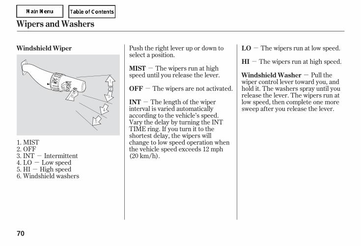
---
-
-
-
-
-
-
MISTOFFINT IntermittentLO Low speedHI High speedWindshield washers
Push the right lever up or down toselect a position.
The wipers run at highspeed until you release the lever.
The wipers are not activated.
The wipers run at low speed.
The wipers run at high speed.
The length of the wiperinterval is varied automaticallyaccording to the vehicle’s speed.Vary the delay by turning the INTTIME ring. If you turn it to theshortest delay, the wipers willchange to low speed operation whenthe vehicle speed exceeds 12 mph(20 km/h).
Pull thewiper control lever toward you, andhold it. The washers spray until yourelease the lever. The wipers run atlow speed, then complete one moresweep after you release the lever.
1.2.3.4.5.6.
Windshield Wiper
MIST
OFF
LO
HI
INT
Windshield Washer
Wipers and Washers
70
05/09/02 11:43:42 31SDR610 0073
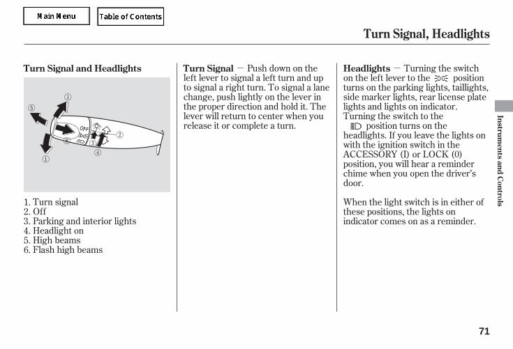
- -
Turn signalOffParking and interior lightsHeadlight onHigh beamsFlash high beams
Push down on theleft lever to signal a left turn and upto signal a right turn. To signal a lanechange, push lightly on the lever inthe proper direction and hold it. Thelever will return to center when yourelease it or complete a turn.
Turning the switchon the left lever to the positionturns on the parking lights, taillights,side marker lights, rear license platelights and lights on indicator.Turning the switch to the
position turns on theheadlights. If you leave the lights onwith the ignition switch in theACCESSORY (I) or LOCK (0)position, you will hear a reminderchime when you open the driver’sdoor.
When the light switch is in either ofthese positions, the lights onindicator comes on as a reminder.
1.2.3.4.5.6.
Turn Signal and Headlights Turn Signal Headlights
Turn Signal, Headlights
Instruments
andC
ontrols
71
05/09/02 11:43:49 31SDR610 0074
- If you remove the key from theignition switch with the headlightswitch on, but do not open the doorand get out, the lights will turn offafter 10 minutes.
The lights will turn on again whenyou unlock or open the driver’s door.If you unlock the door, but do notopen it within 15 seconds, the lightswill go off. With the driver’s dooropen, you will hear a lights-onreminder chime.
To turn on the highbeams, push the lever forward untilyou hear a click. The blue high beamindicator will come on (see page ).To turn off the high beams, pull thelever back. To flash the high beams,pull the lever farther back, and thenrelease it. The high beams remain onuntil the lever is released.
This feature turns off the headlights,parking lights, side marker lights,taillights, and rear license plate lightswithin 15 seconds of removing thekey from the ignition switch andclosing the driver’s door.
This feature activates if you leavethe headlight switch in the or
position, remove the key, thenopen and close the driver’s door.
58
Automatic Lighting Off FeatureHigh Beams
Headlights, Automatic Lighting Off Feature
72
05/09/02 11:43:55 31SDR610 0075
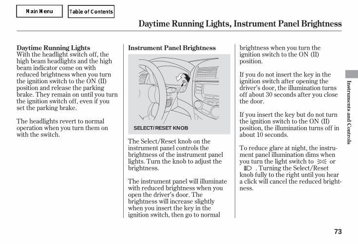
With the headlight switch off, thehigh beam headlights and the highbeam indicator come on withreduced brightness when you turnthe ignition switch to the ON (II)position and release the parkingbrake. They remain on until you turnthe ignition switch off, even if youset the parking brake.
The headlights revert to normaloperation when you turn them onwith the switch.
The instrument panel will illuminatewith reduced brightness when youopen the driver’s door. Thebrightness will increase slightlywhen you insert the key in theignition switch, then go to normal
brightness when you turn theignition switch to the ON (II)position.
The Select/Reset knob on theinstrument panel controls thebrightness of the instrument panellights. Turn the knob to adjust thebrightness.
If you do not insert the key in theignition switch after opening thedriver’s door, the illumination turnsoff about 30 seconds after you closethe door.
To reduce glare at night, the instru-ment panel illumination dims whenyou turn the light switch to or
. Turning the Select/Resetknob fully to the right until you heara click will cancel the reduced bright-ness.
If you insert the key but do not turnthe ignition switch to the ON (II)position, the illumination turns off inabout 10 seconds.
Instrument Panel BrightnessDaytime Running Lights
Daytime Running Lights, Instrument Panel Brightness
Instruments
andC
ontrols
73
SELECT/RESET KNOB
05/09/02 11:44:02 31SDR610 0076
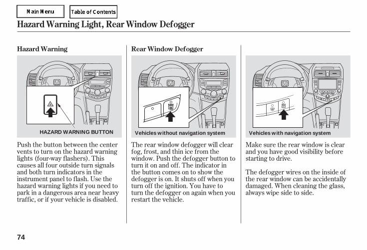
Push the button between the centervents to turn on the hazard warninglights (four-way flashers). Thiscauses all four outside turn signalsand both turn indicators in theinstrument panel to flash. Use thehazard warning lights if you need topark in a dangerous area near heavytraffic, or if your vehicle is disabled.
The rear window defogger will clearfog, frost, and thin ice from thewindow. Push the defogger button toturn it on and off. The indicator inthe button comes on to show thedefogger is on. It shuts off when youturn off the ignition. You have toturn the defogger on again when yourestart the vehicle.
Make sure the rear window is clearand you have good visibility beforestarting to drive.
The defogger wires on the inside ofthe rear window can be accidentallydamaged. When cleaning the glass,always wipe side to side.
Rear Window DefoggerHazard Warning
Hazard Warning Light, Rear Window Defogger
74
Vehicles without navigation systemHAZARD WARNING BUTTON Vehicles with navigation system
05/09/02 11:44:10 31SDR610 0077
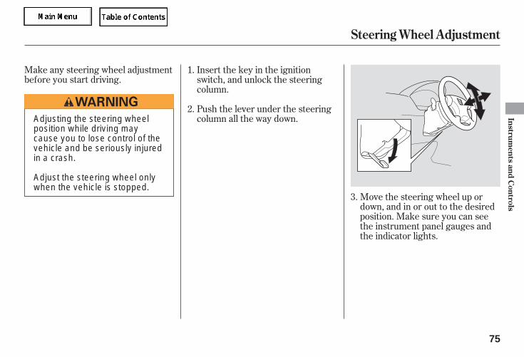
Make any steering wheel adjustmentbefore you start driving.
Move the steering wheel up ordown, and in or out to the desiredposition. Make sure you can seethe instrument panel gauges andthe indicator lights.
Insert the key in the ignitionswitch, and unlock the steeringcolumn.
Push the lever under the steeringcolumn all the way down.
1.
2.
3.
Steering Wheel Adjustment
Instruments
andC
ontrols
75
Adjusting the steering wheelposition while driving maycause you to lose control of thevehicle and be seriously injuredin a crash.
Adjust the steering wheel onlywhen the vehicle is stopped.
05/09/02 11:44:16 31SDR610 0078
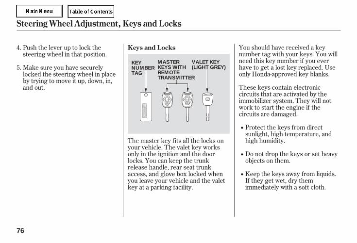
You should have received a keynumber tag with your keys. You willneed this key number if you everhave to get a lost key replaced. Useonly Honda-approved key blanks.
These keys contain electroniccircuits that are activated by theimmobilizer system. They will notwork to start the engine if thecircuits are damaged.
Protect the keys from directsunlight, high temperature, andhigh humidity.
Do not drop the keys or set heavyobjects on them.
Keep the keys away from liquids.If they get wet, dry themimmediately with a soft cloth.
The master key fits all the locks onyour vehicle. The valet key worksonly in the ignition and the doorlocks. You can keep the trunkrelease handle, rear seat trunkaccess, and glove box locked whenyou leave your vehicle and the valetkey at a parking facility.
Push the lever up to lock thesteering wheel in that position.
Make sure you have securelylocked the steering wheel in placeby trying to move it up, down, in,and out.
4.
5.
Keys and Locks
Steering Wheel Adjustment, Keys and Locks
76
KEYNUMBERTAG
VALET KEY(LIGHT GREY)
MASTERKEYS WITHREMOTETRANSMITTER
05/09/02 11:44:24 31SDR610 0079
If the system repeatedly does notrecognize the coding of your key,contact your dealer.
Do not attempt to alter this systemor add other devices to it. Electricalproblems could result that may makeyour vehicle undrivable.
If you lose your key and you cannotstart the engine, contact your dealer.
The immobilizer system protectsyour vehicle from theft. If animproperly-coded key (or otherdevice) is used, the engine will notstart.
When you turn the ignition switch tothe ON (II) position, the immobilizersystem indicator should come on fora few seconds, then go off. If theindicator starts to blink, it means thesystem does not recognize thecoding of the key. Turn the ignitionswitch to the LOCK (0) position,remove the key, reinsert it, and turnthe ignition switch to the ON (II)position again.
The system may not recognize yourkey’s coding if another immobilizerkey or other metal object (i.e. keyfob) is near the ignition switch whenyou insert the key.
As required by the FCC:This device complies with Part 15 of theFCC rules. Operation is subject to thefollowing two conditions: (1) This devicemay not cause harmful interference, and(2) this device must accept anyinterference received, includinginterference that may cause undesiredoperation.
Changes or modifications not expresslyapproved by the party responsible forcompliance could void the user’sauthority to operate the equipment.
This device complies with IndustryCanada Standard RSS-210.Operation is subject to the following twoconditions: (1) this device may not causeinterference, and (2) this device mustaccept any interference that may causeundesired operation of the device.
Immobilizer System
Instruments
andC
ontrols
77
05/09/02 11:44:31 31SDR610 0080
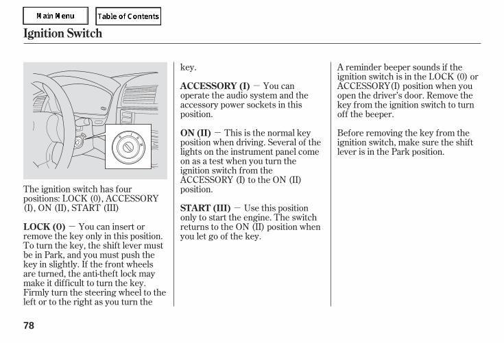
-
-
-
-
The ignition switch has fourpositions: LOCK (0), ACCESSORY(I), ON (II), START (III)
You can insert orremove the key only in this position.To turn the key, the shift lever mustbe in Park, and you must push thekey in slightly. If the front wheelsare turned, the anti-theft lock maymake it difficult to turn the key.Firmly turn the steering wheel to theleft or to the right as you turn the
key.
You canoperate the audio system and theaccessory power sockets in thisposition.
This is the normal keyposition when driving. Several of thelights on the instrument panel comeon as a test when you turn theignition switch from theACCESSORY (I) to the ON (II)position.
A reminder beeper sounds if theignition switch is in the LOCK (0) orACCESSORY(I) position when youopen the driver’s door. Remove thekey from the ignition switch to turnoff the beeper.
Before removing the key from theignition switch, make sure the shiftlever is in the Park position.
Use this positiononly to start the engine. The switchreturns to the ON (II) position whenyou let go of the key.
LOCK (0)
ACCESSORY (I)
ON (II)
START (III)
Ignition Switch
78
05/09/02 11:44:37 31SDR610 0081
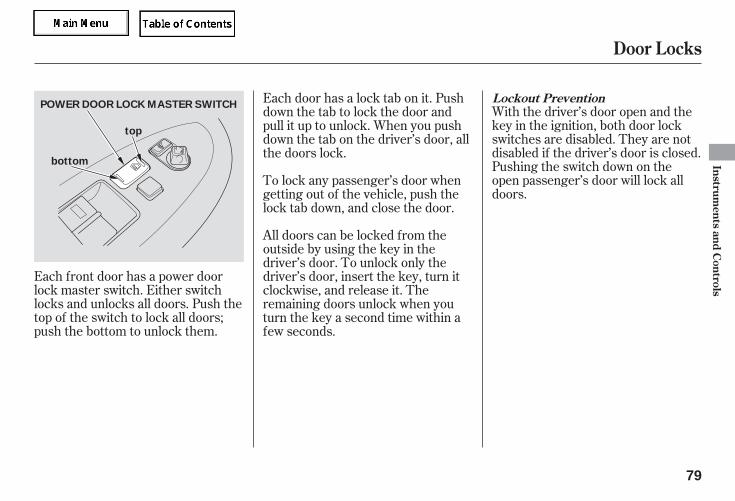
With the driver’s door open and thekey in the ignition, both door lockswitches are disabled. They are notdisabled if the driver’s door is closed.Pushing the switch down on theopen passenger’s door will lock alldoors.
Each front door has a power doorlock master switch. Either switchlocks and unlocks all doors. Push thetop of the switch to lock all doors;push the bottom to unlock them.
Each door has a lock tab on it. Pushdown the tab to lock the door andpull it up to unlock. When you pushdown the tab on the driver’s door, allthe doors lock.
To lock any passenger’s door whengetting out of the vehicle, push thelock tab down, and close the door.
All doors can be locked from theoutside by using the key in thedriver’s door. To unlock only thedriver’s door, insert the key, turn itclockwise, and release it. Theremaining doors unlock when youturn the key a second time within afew seconds.
Lockout Prevention
Door Locks
Instruments
andC
ontrols
79
top
bottom
POWER DOOR LOCK MASTER SWITCH
05/09/02 11:44:44 31SDR610 0082
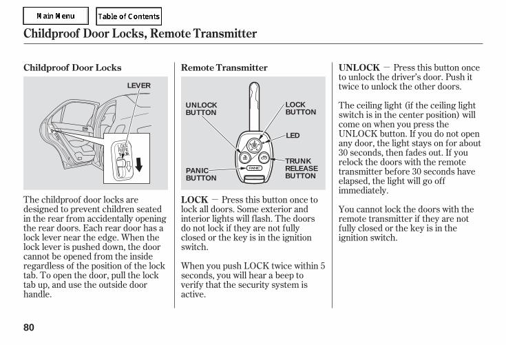
-
-
The childproof door locks aredesigned to prevent children seatedin the rear from accidentally openingthe rear doors. Each rear door has alock lever near the edge. When thelock lever is pushed down, the doorcannot be opened from the insideregardless of the position of the locktab. To open the door, pull the locktab up, and use the outside doorhandle.
Press this button once tolock all doors. Some exterior andinterior lights will flash. The doorsdo not lock if they are not fullyclosed or the key is in the ignitionswitch.
When you push LOCK twice within 5seconds, you will hear a beep toverify that the security system isactive.
Press this button onceto unlock the driver’s door. Push ittwice to unlock the other doors.
The ceiling light (if the ceiling lightswitch is in the center position) willcome on when you press theUNLOCK button. If you do not openany door, the light stays on for about30 seconds, then fades out. If yourelock the doors with the remotetransmitter before 30 seconds haveelapsed, the light will go offimmediately.
You cannot lock the doors with theremote transmitter if they are notfully closed or the key is in theignition switch.
Remote TransmitterChildproof Door Locks
LOCK
UNLOCK
Childproof Door Locks, Remote Transmitter
80
LEVER
LOCKBUTTON
UNLOCKBUTTON
PANICBUTTON
LED
TRUNKRELEASEBUTTON
05/09/02 11:44:52 31SDR610 0083
-
-
Avoid dropping or throwing thetransmitter.
Protect the transmitter fromextreme temperature.
Do not immerse the transmitter inany liquid.
If you lose a transmitter, thereplacement needs to bereprogrammed by your dealer.
After the doors automatically relock,the security system will be active.
Press this button forabout 1 second to attract attention;the horn will sound and the exteriorlights will flash for about 30 seconds.To cancel panic mode, press anyother button on the remotetransmitter, or turn the ignitionswitch to the ON (II) position.
Press thisbutton for about 1 second to openthe trunk. You cannot open the trunkif the key is in the ignition switch.
Battery type: CR1616
If it takes several pushes on thebutton to lock or unlock the doors,replace the battery as soon aspossible.
If you unlock the doors with theremote transmitter, but do not openany of the doors within 30 seconds,the doors automatically relock.
Remote Transmitter
PANIC
TRUNK RELEASE
Remote Transmitter Care Replacing the TransmitterBattery
Instruments
andC
ontrols
81
05/09/02 11:45:00 31SDR610 0084
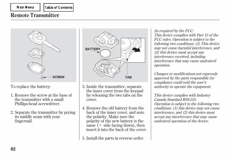
+
To replace the battery:
Remove the screw at the base ofthe transmitter with a smallPhillips-head screwdriver.
Separate the transmitter by pryingits middle seam with yourfingernail.
Inside the transmitter, separatethe inner cover from the keypadby releasing the two tabs on thecover.
Remove the old battery from theback of the inner cover, and notethe polarity. Make sure thepolarity of the new battery is thesame ( side facing down), theninsert it into the back of the cover.
Install the parts in reverse order.
1.
2.
3.
4.
5.
As required by the FCC:This device complies with Part 15 of theFCC rules. Operation is subject to thefollowing two conditions: (1) This devicemay not cause harmful interference, and(2) this device must accept anyinterference received, includinginterference that may cause undesiredoperation.
Changes or modifications not expresslyapproved by the party responsible forcompliance could void the user’sauthority to operate the equipment.
This device complies with IndustryCanada Standard RSS-210.Operation is subject to the following twoconditions: (1) this device may not causeinterference, and (2) this device mustaccept any interference that may causeundesired operation of the device.
Remote Transmitter
82
SCREW
BATTERY
TAB
05/09/02 11:45:09 31SDR610 0085
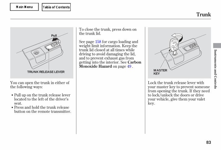
Pull up on the trunk release leverlocated to the left of the driver’sseat.
Lock the trunk release lever withyour master key to prevent someonefrom opening the trunk. If they needto lock/unlock the doors or driveyour vehicle, give them your valetkey.
You can open the trunk in either ofthe following ways:
Press and hold the trunk releasebutton on the remote transmitter.
To close the trunk, press down onthe trunk lid.
See page for cargo loading andweight limit information. Keep thetrunk lid closed at all times whiledriving to avoid damaging the lid,and to prevent exhaust gas fromgetting into the interior. See
on page .
158
49
Trunk
CarbonMonoxide Hazard
Instruments
andC
ontrols
83
Pull
TRUNK RELEASE LEVERMASTERKEY
05/09/02 11:45:16 31SDR610 0086
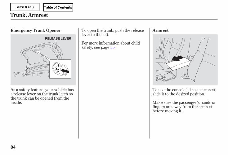
As a safety feature, your vehicle hasa release lever on the trunk latch sothe trunk can be opened from theinside.
To open the trunk, push the releaselever to the left.
To use the console lid as an armrest,slide it to the desired position.
Make sure the passenger’s hands orfingers are away from the armrestbefore moving it.
For more information about childsafety, see page .35
Emergency Trunk Opener Armrest
Trunk, Armrest
84
RELEASE LEVER
05/09/02 11:45:23 31SDR610 0087
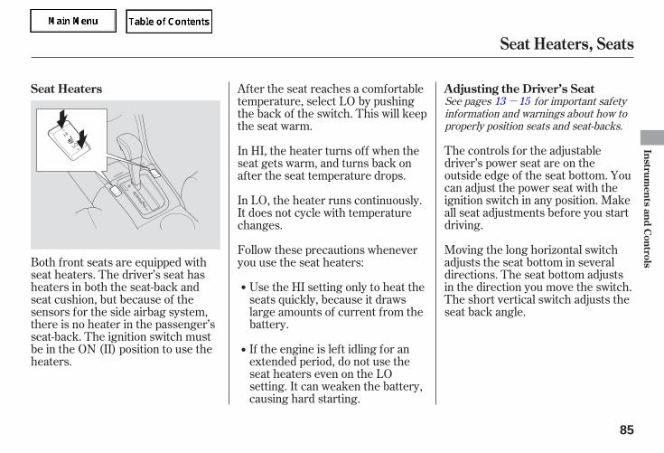
-See pages for important safetyinformation and warnings about how toproperly position seats and seat-backs.
13 15
The controls for the adjustabledriver’s power seat are on theoutside edge of the seat bottom. Youcan adjust the power seat with theignition switch in any position. Makeall seat adjustments before you startdriving.
Moving the long horizontal switchadjusts the seat bottom in severaldirections. The seat bottom adjustsin the direction you move the switch.The short vertical switch adjusts theseat back angle.
Both front seats are equipped withseat heaters. The driver’s seat hasheaters in both the seat-back andseat cushion, but because of thesensors for the side airbag system,there is no heater in the passenger’sseat-back. The ignition switch mustbe in the ON (II) position to use theheaters.
If the engine is left idling for anextended period, do not use theseat heaters even on the LOsetting. It can weaken the battery,causing hard starting.
Use the HI setting only to heat theseats quickly, because it drawslarge amounts of current from thebattery.
Follow these precautions wheneveryou use the seat heaters:
In LO, the heater runs continuously.It does not cycle with temperaturechanges.
In HI, the heater turns off when theseat gets warm, and turns back onafter the seat temperature drops.
After the seat reaches a comfortabletemperature, select LO by pushingthe back of the switch. This will keepthe seat warm.
Adjusting the Driver’s SeatSeat Heaters
Seat Heaters, Seats
Instruments
andC
ontrols
85
05/09/02 11:45:33 31SDR610 0088
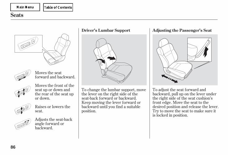
To adjust the seat forward andbackward, pull up on the lever underthe right side of the seat cushion’sfront edge. Move the seat to thedesired position and release the lever.Try to move the seat to make sure itis locked in position.
Moves the seatforward and backward.
Moves the front of theseat up or down andthe rear of the seat upor down.
Raises or lowers theseat.
Adjusts the seat-backangle forward orbackward.
To change the lumbar support, movethe lever on the right side of theseat-back forward or backward.Keep moving the lever forward orbackward until you find a suitableposition.
Adjusting the Passenger’s SeatDriver’s Lumbar Support
Seats
86
05/09/02 11:45:43 31SDR610 0089
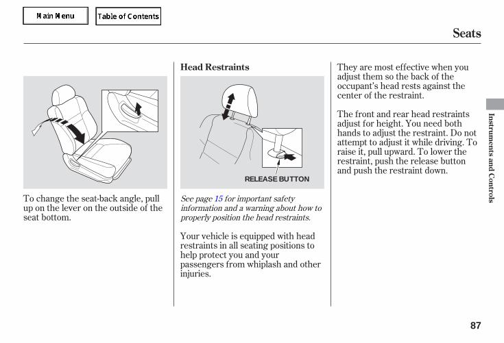
To change the seat-back angle, pullup on the lever on the outside of theseat bottom.
Your vehicle is equipped with headrestraints in all seating positions tohelp protect you and yourpassengers from whiplash and otherinjuries.
They are most effective when youadjust them so the back of theoccupant’s head rests against thecenter of the restraint.
The front and rear head restraintsadjust for height. You need bothhands to adjust the restraint. Do notattempt to adjust it while driving. Toraise it, pull upward. To lower therestraint, push the release buttonand push the restraint down.
See page for important safetyinformation and a warning about how toproperly position the head restraints.
15
Head Restraints
Seats
Instruments
andC
ontrols
87
RELEASE BUTTON
05/09/02 11:45:49 31SDR610 0090
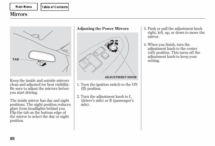
Turn the ignition switch to the ON(II) position.
Push or pull the adjustment knobright, left, up, or down to move themirror.
Keep the inside and outside mirrorsclean and adjusted for best visibility.Be sure to adjust the mirrors beforeyou start driving.
The inside mirror has day and nightpositions. The night position reducesglare from headlights behind you.Flip the tab on the bottom edge ofthe mirror to select the day or nightposition.
Turn the adjustment knob to L(driver’s side) or R (passenger’sside).
When you finish, turn theadjustment knob to the center(off) position. This turns off theadjustment knob to keep yoursetting.
1.
2.
3.
4.
Mirrors
Adjusting the Power Mirrors
88
TAB
ADJUSTMENT KNOB
05/09/02 11:45:57 31SDR610 0091
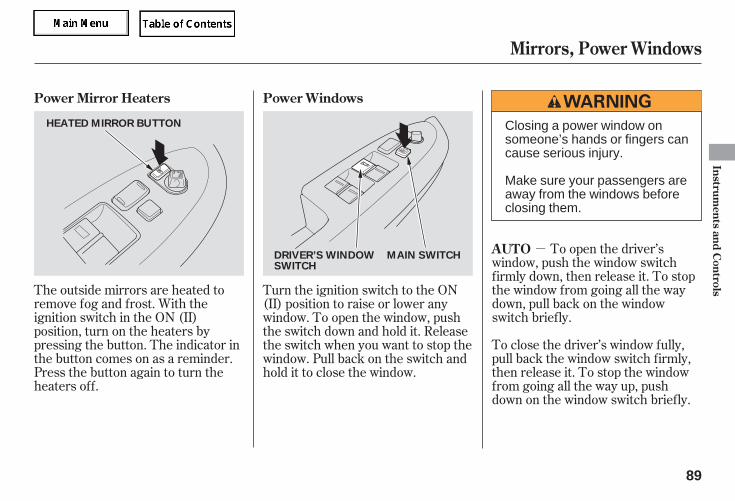
- To open the driver’swindow, push the window switchfirmly down, then release it. To stopthe window from going all the waydown, pull back on the windowswitch briefly.
To close the driver’s window fully,pull back the window switch firmly,then release it. To stop the windowfrom going all the way up, pushdown on the window switch briefly.
The outside mirrors are heated toremove fog and frost. With theignition switch in the ON (II)position, turn on the heaters bypressing the button. The indicator inthe button comes on as a reminder.Press the button again to turn theheaters off.
Turn the ignition switch to the ON(II) position to raise or lower anywindow. To open the window, pushthe switch down and hold it. Releasethe switch when you want to stop thewindow. Pull back on the switch andhold it to close the window.
Power Windows
AUTO
Power Mirror Heaters
Mirrors, Power Windows
Instruments
andC
ontrols
89
DRIVER’S WINDOWSWITCH
MAIN SWITCH
HEATED MIRROR BUTTON Closing a power window onsomeone’s hands or fingers cancause serious injury.
Make sure your passengers areaway from the windows beforeclosing them.
05/09/02 11:46:04 31SDR610 0092
- If the driver’swindow senses any obstacle while itis closing automatically, it willreverse direction, and then stop. Toclose the window, remove theobstacle, then use the window switchagain.
Auto reverse stops sensing when thewindow is almost closed. You shouldalways check that all passengers andobjects are away from the windowbefore closing it.
If your vehicle’s battery isdisconnected or goes dead, or thedriver’s window fuse is removed, theAUTO function will be disabled. Thepower window system needs to bereset after reconnecting the batteryor installing the fuse.
Start the engine. Push down andhold the driver’s window switchuntil the window is fully open.
Pull and hold the driver’s windowswitch to close the windowcompletely, then hold the switchfor about 2 seconds.
If the power windows do not operateproperly after resetting, have yourvehicle checked by your dealer.
To open or close the driver’s windowpartially, push down or pull back onthe window switch lightly and hold it.The window will stop when yourelease the switch.
The passenger windows cannot beraised or lowered if the MAIN switchis OFF. Keep the MAIN switch offwhen you have children in thevehicle so they do not injurethemselves by operating thewindows unintentionally.
1.
2.
AUTO REVERSE
Power Windows
90
05/09/02 11:46:11 31SDR610 0093
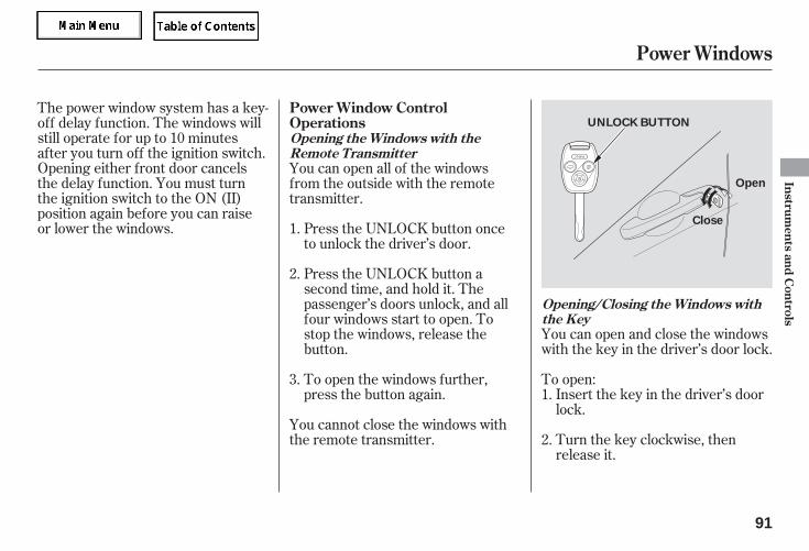
The power window system has a key-off delay function. The windows willstill operate for up to 10 minutesafter you turn off the ignition switch.Opening either front door cancelsthe delay function. You must turnthe ignition switch to the ON (II)position again before you can raiseor lower the windows.
You can open and close the windowswith the key in the driver’s door lock.
To open:Insert the key in the driver’s doorlock.
Turn the key clockwise, thenrelease it.
You cannot close the windows withthe remote transmitter.
To open the windows further,press the button again.
Press the UNLOCK button asecond time, and hold it. Thepassenger’s doors unlock, and allfour windows start to open. Tostop the windows, release thebutton.
Press the UNLOCK button onceto unlock the driver’s door.
You can open all of the windowsfrom the outside with the remotetransmitter.
1.
2.
3.1.
2.
Opening/Closing the Windows withthe Key
Opening the Windows with theRemote Transmitter
Power Windows
Power Window ControlOperations
Instruments
andC
ontrols
91
UNLOCK BUTTON
Open
Close
05/09/02 11:46:22 31SDR610 0094
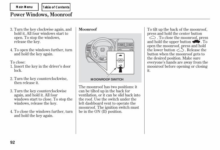
Turn the key clockwise again, andhold it. All four windows start toopen. To stop the windows,release the key.
To open the windows further, turnand hold the key again.
To close:Insert the key in the driver’s doorlock.
Turn the key counterclockwise,then release it.
Turn the key counterclockwiseagain, and hold it. All fourwindows start to close. To stop thewindows, release the key.
To close the windows further, turnand hold the key again.
The moonroof has two positions: itcan be tilted up in the back forventilation, or it can be slid back intothe roof. Use the switch under theleft dashboard vent to operate themoonroof. The ignition switch mustbe in the ON (II) position.
To tilt up the back of the moonroof,press and hold the center button
. To close the moonroof, pressand hold the upper button . Toopen the moonroof, press and holdthe lower button . Release thebutton when the moonroof gets tothe desired position. Make sureeveryone’s hands are away from themoonroof before opening or closingit.
1.
2.
3.
4.
3.
4.
Power Windows, Moonroof
Moonroof
92
MOONROOF SWITCH
05/09/02 11:46:32 31SDR610 0095
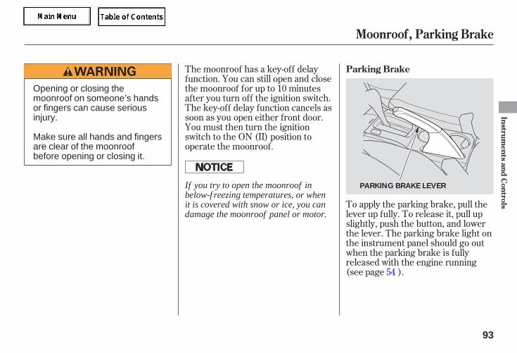
To apply the parking brake, pull thelever up fully. To release it, pull upslightly, push the button, and lowerthe lever. The parking brake light onthe instrument panel should go outwhen the parking brake is fullyreleased with the engine running(see page ).
The moonroof has a key-off delayfunction. You can still open and closethe moonroof for up to 10 minutesafter you turn off the ignition switch.The key-off delay function cancels assoon as you open either front door.You must then turn the ignitionswitch to the ON (II) position tooperate the moonroof.
54
Parking Brake
Moonroof, Parking Brake
Instruments
andC
ontrols
93
PARKING BRAKE LEVER
Opening or closing themoonroof on someone’s handsor fingers can cause seriousinjury.
Make sure all hands and fingersare clear of the moonroofbefore opening or closing it.
If you try to open the moonroof inbelow-f reezing temperatures, or whenit is covered with snow or ice, you candamage the moonroof panel or motor.
05/09/02 11:46:38 31SDR610 0096
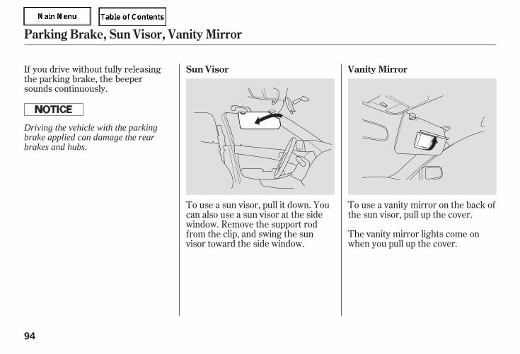
The vanity mirror lights come onwhen you pull up the cover.
To use a vanity mirror on the back ofthe sun visor, pull up the cover.
If you drive without fully releasingthe parking brake, the beepersounds continuously.
To use a sun visor, pull it down. Youcan also use a sun visor at the sidewindow. Remove the support rodfrom the clip, and swing the sunvisor toward the side window.
Vanity MirrorSun Visor
Parking Brake, Sun Visor, Vanity Mirror
94
Driving the vehicle with the parkingbrake applied can damage the rearbrakes and hubs.
05/09/02 11:46:44 31SDR610 0097
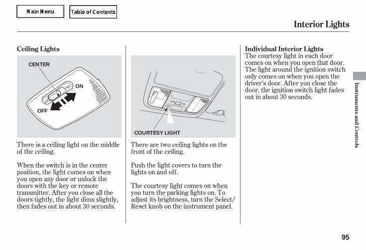
There is a ceiling light on the middleof the ceiling.
There are two ceiling lights on thefront of the ceiling.
Push the light covers to turn thelights on and off.
The courtesy light comes on whenyou turn the parking lights on. Toadjust its brightness, turn the Select/Reset knob on the instrument panel.
When the switch is in the centerposition, the light comes on whenyou open any door or unlock thedoors with the key or remotetransmitter. After you close all thedoors tightly, the light dims slightly,then fades out in about 30 seconds.
The courtesy light in each doorcomes on when you open that door.The light around the ignition switchonly comes on when you open thedriver’s door. After you close thedoor, the ignition switch light fadesout in about 30 seconds.
Ceiling Lights Individual Interior Lights
Interior Lights
Instruments
andC
ontrols
95
ON
OFF
COURTESY LIGHT
CENTER
05/09/02 11:46:52 31SDR610 0098
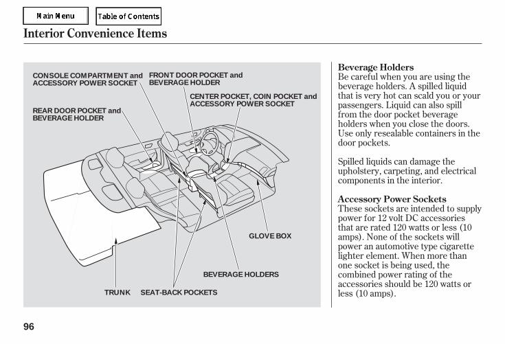
Be careful when you are using thebeverage holders. A spilled liquidthat is very hot can scald you or yourpassengers. Liquid can also spillfrom the door pocket beverageholders when you close the doors.Use only resealable containers in thedoor pockets.
Spilled liquids can damage theupholstery, carpeting, and electricalcomponents in the interior.
These sockets are intended to supplypower for 12 volt DC accessoriesthat are rated 120 watts or less (10amps). None of the sockets willpower an automotive type cigarettelighter element. When more thanone socket is being used, thecombined power rating of theaccessories should be 120 watts orless (10 amps).
Interior Convenience Items
Beverage Holders
Accessory Power Sockets
96
BEVERAGE HOLDERS
GLOVE BOX
TRUNK SEAT-BACK POCKETS
CONSOLE COMPARTMENT andACCESSORY POWER SOCKET
REAR DOOR POCKET andBEVERAGE HOLDER
FRONT DOOR POCKET andBEVERAGE HOLDER
CENTER POCKET, COIN POCKET andACCESSORY POWER SOCKET
05/09/02 11:46:58 31SDR610 0099
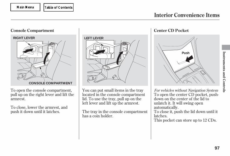
To open the console compartment,pull up on the right lever and lift thearmrest.
To close, lower the armrest, andpush it down until it latches.
You can put small items in the traylocated in the console compartmentlid. To use the tray, pull up on theleft lever and lift up the armrest.
The tray in the console compartmenthas a coin holder.
To open the center CD pocket, push-down on the center of the lid tounlatch it. It will swing openautomatically.To close it, push the lid down until itlatches.This pocket can store up to 12 CDs.
For vehicles without Navigation System
Interior Convenience Items
Console Compartment Center CD Pocket
Instruments
andC
ontrols
97
CONSOLE COMPARTMENT
RIGHT LEVER LEFT LEVER
Push
05/09/02 11:47:07 31SDR610 0100
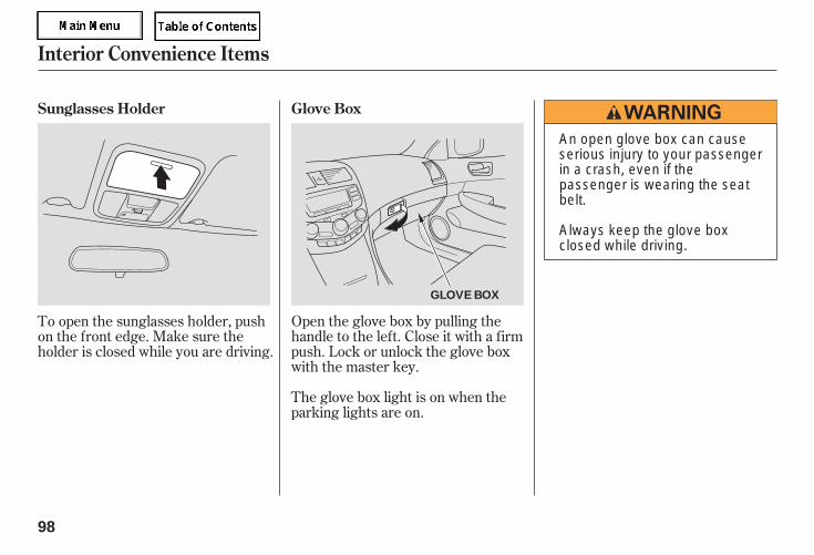
Open the glove box by pulling thehandle to the left. Close it with a firmpush. Lock or unlock the glove boxwith the master key.
To open the sunglasses holder, pushon the front edge. Make sure theholder is closed while you are driving.
The glove box light is on when theparking lights are on.
Sunglasses Holder Glove Box
Interior Convenience Items
98
GLOVE BOX
An open glove box can causeserious injury to your passengerin a crash, even if thepassenger is wearing the seatbelt.
Always keep the glove boxclosed while driving.
05/09/02 11:47:14 31SDR610 0101
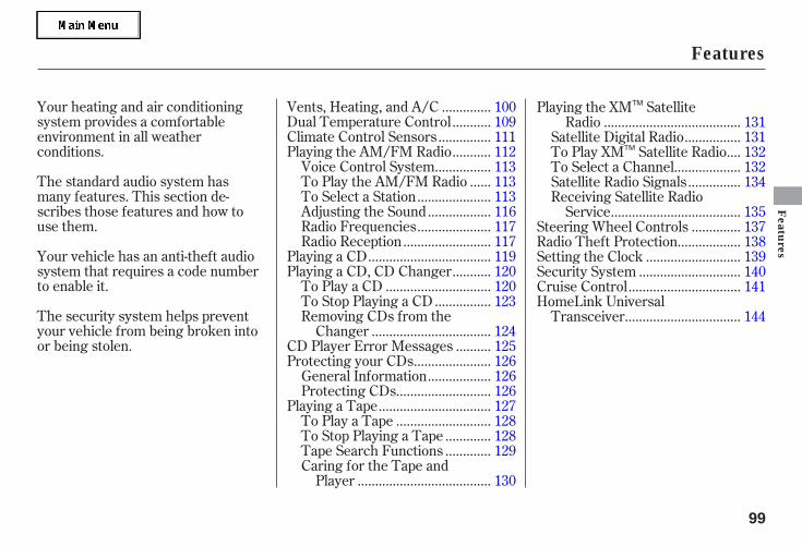
Your heating and air conditioningsystem provides a comfortableenvironment in all weatherconditions.
The standard audio system hasmany features. This section de-scribes those features and how touse them.
Your vehicle has an anti-theft audiosystem that requires a code numberto enable it.
The security system helps preventyour vehicle from being broken intoor being stolen.
.............Vents, Heating, and A/C . 100..........Dual Temperature Control . 109
..............Climate Control Sensors . 111..........Playing the AM/FM Radio . 112
...............Voice Control System . 113.....To Play the AM/FM Radio . 113
....................To Select a Station . 113.................Adjusting the Sound . 116
....................Radio Frequencies . 117........................Radio Reception . 117
..................................Playing a CD . 119..........Playing a CD, CD Changer . 120
.............................To Play a CD . 120...............To Stop Playing a CD . 123
Removing CDs from the.................................Changer . 124
.........CD Player Error Messages . 125.....................Protecting your CDs . 126
.................General Information . 126..........................Protecting CDs . 126
...............................Playing a Tape . 127..........................To Play a Tape . 128
............To Stop Playing a Tape . 128
............Tape Search Functions . 129Caring for the Tape and
.....................................Player . 130
Playing the XM Satellite......................................Radio . 131
...............Satellite Digital Radio . 131...To Play XM Satellite Radio . 132
..................To Select a Channel . 132..............Satellite Radio Signals . 134
Receiving Satellite Radio....................................Service . 135
.............Steering Wheel Controls . 137.................Radio Theft Protection . 138
..........................Setting the Clock . 139............................Security System . 140
...............................Cruise Control . 141HomeLink Universal
................................Transceiver . 144
Features
Features
99
TM
TM
05/09/02 11:47:19 31SDR610 0102
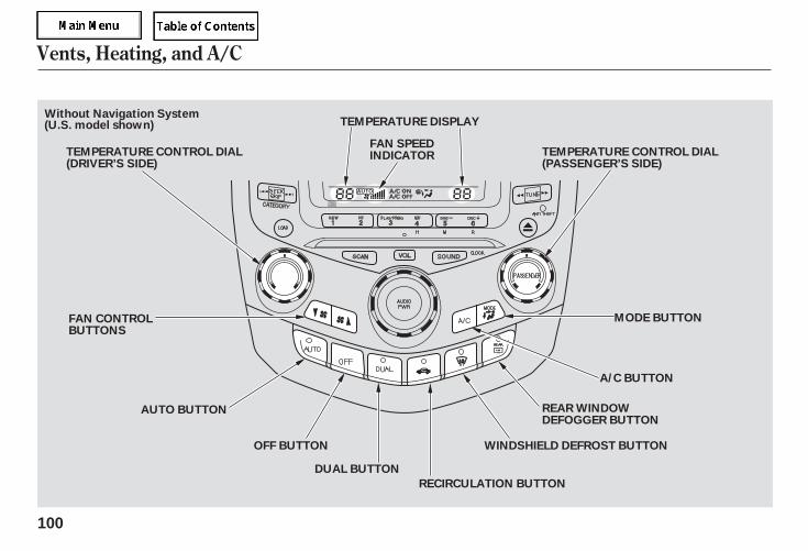
Vents, Heating, and A/C
100
REAR WINDOWDEFOGGER BUTTON
FAN CONTROLBUTTONS
AUTO BUTTON
OFF BUTTON
DUAL BUTTON
A/C BUTTON
TEMPERATURE CONTROL DIAL(DRIVER’S SIDE)
FAN SPEEDINDICATOR
TEMPERATURE DISPLAY
TEMPERATURE CONTROL DIAL(PASSENGER’S SIDE)
Without Navigation System
MODE BUTTON
WINDSHIELD DEFROST BUTTON
RECIRCULATION BUTTON
(U.S. model shown)
05/09/02 11:47:24 31SDR610 0103
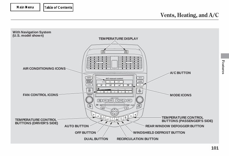
Vents, Heating, and A/C
Features
101
AUTO BUTTON
MODE ICONS
A/C BUTTON
AIR CONDITIONING ICONS
FAN CONTROL ICONS
DUAL BUTTON
TEMPERATURE CONTROLBUTTONS (PASSENGER’S SIDE)
RECIRCULATION BUTTON
WINDSHIELD DEFROST BUTTON
REAR WINDOW DEFOGGER BUTTON
TEMPERATURE CONTROLBUTTONS (DRIVER’S SIDE)
OFF BUTTON
TEMPERATURE DISPLAY
With Navigation System(U.S. model shown)
05/09/02 11:47:29 31SDR610 0104
▲ ▼
The climate control system for yourvehicle can also be operated usingthe voice control system. SeeNavigation section in your QuickStart Guide for an overview of thissystem and the Navigation Systemmanual for complete details.
Turn the temperature control dial onthe driver’s side to adjust the airflowtemperature on both the driver’s andpassenger’s sides at the same time.
When you press the DUAL button,the indicator comes on. When it is on,the airflow temperatures on thedriver’s and passenger’s sides can beadjusted individually.
Press the temperature controlbuttons and on the driver’s sideto adjust the airflow temperature onboth the driver’s and passenger’ssides at the same time.
When you press the DUAL button,the indicator comes on. When it is on,the airflow temperatures on thedriver’s and passenger’s sides can beadjusted individually.
You can manually select the fanspeed by pressing the fan controlbuttons. The fan speed isrepresented by vertical bars in thedisplay.
You can manually select the fanspeed by pressing the A/C buttonnext to the display, and thenpressing the fan control icons.
For vehicles without Navigation System
For vehicles with Navigation System
For vehicles without Navigation System
For vehicles with Navigation System
Only on models equipped withNavigation System
Vents, Heating, and A/C
Voice Control System Temperature ControlFan Control
102
05/09/02 11:47:39 31SDR610 0105
When the recirculation indicator ison, air from the vehicle’s interior issent throughout the system again.When the indicator is off, air isbrought in from the outside of thevehicle (fresh air mode).
The outside air intakes for theheating and cooling system are atthe base of the windshield. Keep thisarea clear of leaves and other debris.
The system should be left in freshair mode under almost all conditions.Keeping the system in recirculationmode, particularly with the A/C off,can cause the windows to fog up.Switch to recirculation mode whendriving through dusty or smokyconditions, then return to fresh airmode.
Press the A/C button to turn the airconditioning on and off. The displayshows ‘‘A/C ON’’ when the airconditioning is on. The displayshows ‘‘A/C OFF’’ when the airconditioning is off.
The display shows ‘‘ON’’ and ‘‘OFF’’after you press the A/C button. Thedisplay shows ‘‘A/C ON’’ after youtouch ‘‘ON’’ to turn the airconditioning on. The display shows‘‘A/C OFF’’ after you touch ‘‘OFF’’ toturn the air conditioning off.
When the A/C is off, the airflowtemperature does not fall below theoutside air temperature. When youset the airflow temperature lowerthan the outside air temperature,make sure the A/C is on.
This button turns the rear windowdefogger on and off (see page ).74
For vehicles without Navigation System
For vehicles with Navigation System
Air Conditioning (A/C) Button
Rear Window Defogger Button
Recirculation Button
Vents, Heating, and A/C
Features
103
05/09/02 11:47:50 31SDR610 0106
Use the mode control buttons oricons to select the vents the air flowsfrom. Some air flows from thedashboard corner vents in all modes.
Air flows from the centerand corner vents in the dashboard.
Air flows from the floorvents.
Airflow is divided betweenthe vents in the dashboard and thefloor vents.
The flow-through ventilation systemdraws in outside air, circulates itthrough the interior, then exhausts itthrough vents near the rear window.
Set the temperature to the lowerlimit.Make sure the A/C is off.Select and fresh air mode.Set the fan to the desired speed.
Airflow is divided betweenthe floor vents and the defrostervents at the base of the windshield.
Air flows from the defrostervents at the base of the windshield.
When you select , the systemautomatically switches to fresh airmode and turns on the A/C.
Each time you press the MODEbutton, the display shows the modeselected.
Press the A/C button to view thedisplay, then touch any of the modeicons on the display.
In AUTO mode, the system controlsthe airflow direction automaticallybetween the dashboard vents andthe floor vents.
1.
2.3.4.
For vehicles without Navigation System
For vehicles with Navigation System
Mode Control Ventilation
Vents, Heating, and A/C
104
05/09/02 11:48:03 31SDR610 0107
▲ ▼
The heater uses engine coolant towarm the air. If the engine is cold, itwill be several minutes before youfeel warm air coming from thesystem.
Air conditioning places an extra loadon the engine. Watch the enginecoolant temperature gauge (see page
). If it moves near the red zone,turn off the A/C until the gaugereading returns to normal.
Press the A/C button; the manualoperation A/C screen will appear.Select the ON icon on the display.Select the desired temperatureand MODE selections. If theoutside air is humid, select theRecirculation mode. If the outsideair is dry, select Fresh Air mode.
you cancool it down more rapidly by partiallyopening the windows, turning on theA/C, and setting the fan tomaximum speed in fresh air mode.
Turn on the A/C by pressing theA/C button.Make sure the temperaturecontrol dial or button is set tomaximum cool.Select .If the outside air is humid, selectRecirculation mode. If the outsideair is dry, select Fresh Air mode.Set the fan to the desired speed.
Select .Set the fan to the desired speed.Adjust the warmth of the air withthe temperature control dial.
Press the A/C button; the manualoperation A/C screen will appear.Select the desired mode and fanspeed icons on the display.Adjust for warmth with thetemperature buttons ( or ).
1.
2.3.
1.
2.
3.4.
5.
1.2.3.
1.
2.
3.
67
If the interior is very warm,
For vehicles without Navigation System
For vehicles with Navigation System
For vehicles without Navigation System
For vehicles with Navigation SystemUsing the Heater Using the A/C
Vents, Heating, and A/C
Features
105
05/09/02 11:48:14 31SDR610 0108
Air conditioning, as it cools, removesmoisture from the air. When used incombination with the heater, itmakes the interior warm and dry.
Turn the fan on.Turn on the air conditioning.Select and Fresh Air mode.Adjust the temperature controldial or buttons to your preference.
This setting is suitable for all drivingconditions whenever the outsidetemperature is above 32°F (0°C).
To remove fog from the inside of thewindows:
Set the fan to the desired speed, orhigh for faster defrosting.Select . The systemautomatically switches to fresh airmode and turns on the A/C. TheA/C indicator will not come on if itwas previously off.Adjust the temperature so theairflow feels warm.Select to help clear therear window.To increase airflow to thewindshield, close the corner vents.
Select . The systemautomatically switches to fresh airmode and turns on the A/C. TheA/C indicator will not come on if itwas previously off.Select .Set the fan and temperaturecontrols to maximum level.
To clear the windows faster, you canclose the dashboard corner vents byrotating the wheel below it. This willsend more warm air to thewindshield defroster vents. Once thewindshield is clear, select the freshair mode to avoid fogging thewindows.
For your safety, make sure you havea clear view through all the windowsbefore driving.
1.2.3.4.
1.
2.
3.
4.
5.
1.
2.3.
To Defog and DefrostTo Dehumidify the Interior To Remove Exterior Frost or IceFrom the Windows
Vents, Heating, and A/C
106
05/09/02 11:48:24 31SDR610 0109
▲ ▼
-
The automatic climate controlsystem adjusts the fan speed andairflow levels to maintain the interiortemperature you select.
Press the AUTO button.
Set the desired temperature byturning the temperature controldial. You will see AUTO in thesystem’s display.
Set the desired temperature bypressing the driver’s sidetemperature control buttons. Press
to raise the temperature orto lower it. The selectedtemperature will show in the upperdisplay.
The system automatically selects theproper mix of conditioned and/orheated air that will, as quickly aspossible, raise or lower the interiortemperature to your preference.
If you set the temperature to itslowest limit (Lo), or its highest limit(Hi), the system runs at full coolingor heating only. It does not regulatethe interior temperature.
In cold weather, the fan will notcome on automatically until theheater starts to develop warm air.
Whenthe indicator in the Dual button is on,the driver’s side and passenger’s sidetemperature can be controlledindependently (see page ).109
Dual Temperature Control
For vehicles without Navigation System
For vehicles with Navigation System
Vents, Heating, and A/C
Automatic Climate Control
Features
107
05/09/02 11:48:32 31SDR610 0110
-
-
You can manually select variousfunctions of the automatic climatecontrol system when it is in AUTO.All other features remainautomatically controlled.
Making any manual selection causesthe word AUTO in the display to goout.
If you press the A/C button next tothe display, the manual selectionswill show in the display. Making anymanual selection causes theindicator in the AUTO button to turnoff.
Press the OFF button. However, alack of airflow can cause thewindows to fog up. You should keepthe fan on at all times so stale air andmoisture do not build up in theinterior and cause fogging.
If you press OFF, the climate controlsystem shuts off.
Keep the system off for shortperiods only.To keep stale air and mustinessfrom collecting, you should havethe fan running at all times.
When the Climate Control System isturned OFF, the temperature in theupper display will also turn off.
For vehicles without Navigation System
For vehicles with Navigation System
For vehicles with Navigation System
Vents, Heating, and A/C
Semi-automatic Operation To Turn Everything Off
108
05/09/02 11:48:42 31SDR610 0111
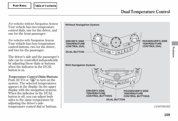
CONTINUED
Your vehicle has two temperaturecontrol dials, one for the driver, andone for the front passenger.
Your vehicle has four temperaturecontrol buttons, two for the driver,and two for the passenger.
The driver’s side and the passenger’sside can be controlled independentlyby adjusting these dials or buttonswhen the indicator in the DUALbutton is on.
Push AUTO or to turn on thesystem. The selected temperaturesappears in the display (in the upperdisplay with the navigation system).When the indicator in the DUALbutton is off, you can adjust bothsides to the same temperature byadjusting the driver’s sidetemperature control dial or buttons.
For vehicles without Navigation System
For vehicles with Navigation System
Dual Temperature Control
Temperature Control Dials/Buttons
Features
109
DUAL BUTTON
Without Navigation System
DUAL BUTTON
DRIVER’S SIDETEMPERATURECONTROL BUTTONS
PASSENGER’S SIDETEMPERATURECONTROL BUTTONS
With Navigation System
DRIVER’S SIDETEMPERATURECONTROL DIAL
PASSENGER’S SIDETEMPERATURECONTROL DIAL
05/09/02 11:48:50 31SDR610 0112
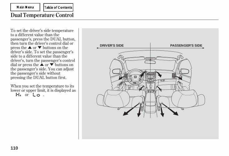
▲ ▼
▲ ▼
To set the driver’s side temperatureto a different value than thepassenger’s, press the DUAL button,then turn the driver’s control dial orpress the or buttons on thedriver’s side. To set the passenger’sside to a different value than thedriver’s, turn the passenger’s controldial or press the or buttons onthe passenger’s side. You can adjustthe passenger’s side withoutpressing the DUAL button first.
When you set the temperature to itslower or upper limit, it is displayed as
or .
Dual Temperature Control
110
DRIVER’S SIDE PASSENGER’S SIDE
05/09/02 11:48:55 31SDR610 0113
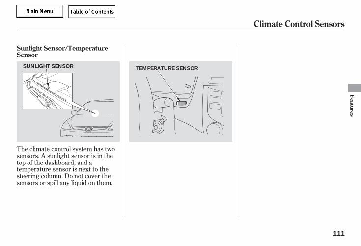
The climate control system has twosensors. A sunlight sensor is in thetop of the dashboard, and atemperature sensor is next to thesteering column. Do not cover thesensors or spill any liquid on them.
Sunlight Sensor/TemperatureSensor
Climate Control Sensors
Features
111
SUNLIGHT SENSOR TEMPERATURE SENSOR
05/09/02 11:49:00 31SDR610 0114
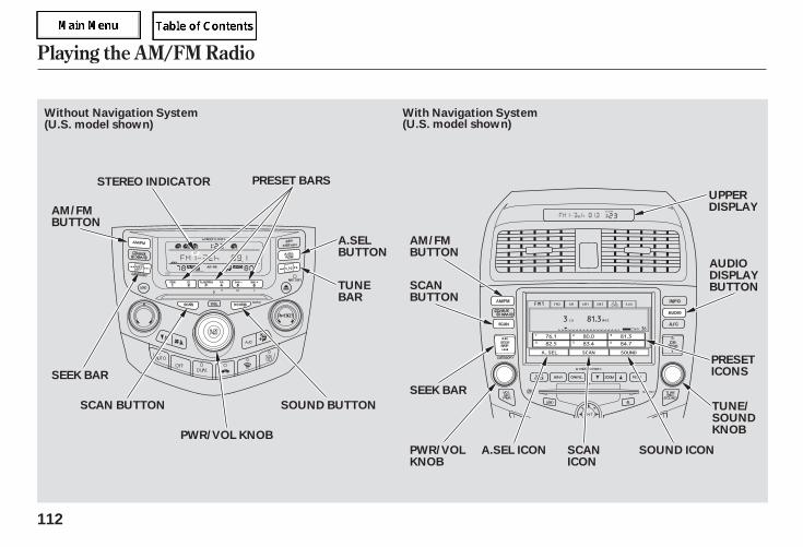
Playing the AM/FM Radio
112
STEREO INDICATOR
SEEK BAR
PRESET BARS
PWR/VOL KNOB
SEEK BAR
SCANBUTTON
PWR/VOLKNOB
UPPERDISPLAY
PRESETICONS
AUDIODISPLAYBUTTON
TUNE/SOUNDKNOB
SCAN BUTTON
TUNEBAR
A.SELBUTTON
SOUND BUTTON
AM/FMBUTTON
AM/FMBUTTON
SOUND ICONSCANICON
Without Navigation System With Navigation System(U.S. model shown)(U.S. model shown)
A.SEL ICON
05/09/02 11:49:05 31SDR610 0115
-
-
You can use any of five methods tofind radio stations on the selectedband: TUNE, SEEK, SCAN, AUTOSELECT, and the preset bars oricons.
Use the TUNE bar orknob to tune the radio to a desiredfrequency. Press the side of thebar or turn the knob to the right totune to a higher frequency, and the
side or turn the knob to the leftto tune to a lower frequency.
The seek functionsearches up and down from thecurrent frequency to find a stationwith a strong signal. To activate it,press the or side of thebar, then release it.
The ignition switch must be in theACCESSORY (I) or the ON (II)position. Turn the system on bypushing the PWR/VOL knob or theFM/AM button. Adjust the volumeby turning the PWR/VOL knob.
Pushing the AUDIO DISPLAYbutton will also turn on the system.
The band and frequency that theradio was last tuned to is displayed.To change bands, press the FM/AMbutton. On the FM band, ST will bedisplayed if the station is broadcast-ing in stereo. Stereo reproduction onAM is not available.
XM satellite radio information isavailable on page .
The audio system for your vehiclecan also be operated using the voicecontrol system. See Navigationsection in your Quick Start Guide foran overview of this system and theNavigation System manual forcomplete details.
131
For vehicles with Navigation System
Only on models equipped withNavigation System
To Select a Station
TUNE
SEEK
To Play the RadioVoice Control System
Playing the AM/FM Radio
Features
113
05/09/02 11:49:14 31SDR610 0116
-- -- Pick the preset number (1 6)you want for that station. Pressthe left or right side of the bar oricon and hold it until you hear abeep.
Repeat steps 1 through 3 to store atotal of six stations on AM andtwelve stations on FM.
Each side of the bars (16) or preset icon can store onefrequency on AM, and twofrequencies on FM.
Select the desired band, AM orFM. FM1 and FM2 let you storetwo frequencies with each presetbar or icon.
The scan function samplesall stations with strong signals on theselected band. To activate it, pressthe SCAN button, then release it.You will see SCAN in the display.The system will scan for a stationwith a strong signal. When it findsone, it will stop and play that stationfor about 5 seconds.
If you do nothing, the system willscan for the next strong station andplay it for 5 seconds. When it plays astation you want to listen to, pressthe SCAN button again.
Push the AUDIO DISPLAY buttonto view the preset icons.
Use the tune, seek, or scanfunction to tune the radio to adesired station.
1.
2.
3.
4.
For vehicles with Navigation System
PresetSCAN
Playing the AM/FM Radio
114
05/09/02 11:49:21 31SDR610 0117
-
-
If you do not like the stations AutoSelect has stored, you can storeother frequencies on the preset barsor icons. Use the TUNE, SEEK, orSCAN function to find stations, thenstore them in the preset bars oricons as described previously.
If you aretraveling far from home and can nolonger receive your preset stations,you can use the auto select feature tofind stations in the local area.
The preset frequencies will be lost ifyour vehicle’s battery goes dead, isdisconnected, or the radio fuse isremoved.
Press the A. SEL button or touch theA. SEL icon. A. SEL will flash in thedisplay, and the system will go intoscan mode for several seconds. Itstores the frequencies of six AM,and twelve FM stations in the presetbars (1 6) or icons. You will see a‘‘0’’ displayed after pressing a presetbar or icon if Auto Select cannot finda strong station for every preset baror icon.
press theA. SEL button or A. SEL icon. Thisrestores the presets you originallyset.
To turn off Auto Select,
Playing the AM/FM Radio
AUTO SELECT
Features
115
05/09/02 11:49:26 31SDR610 0118
-
-
+ -
For vehicles without Navigation System
For vehicles with Navigation System
For vehicles with Navigation System
Press the SOUND button or icon, orpress the TUNE knob repeatedly todisplay the BASS, TREBLE,BALANCE, and FADER settings.
These twomodes adjust the strength of thesound coming from each speaker.BALANCE adjusts the side-to-sidestrength, while FADER adjusts thefront-to-back strength.
Use the TREBLE/BASS modes to adjust the tone toyour liking.
If you want to adjust the sound whilethe radio/CD is playing, push theAUDIO DISPLAY button, then touchthe SOUND icon in the display.
Each mode is shown in the display asit changes. Turn the PWR/VOLknob to adjust the setting to yourliking. When the level reaches thecenter, you will see a ‘‘ ’’ in thedisplay.
To adjust treble and bass, touch the‘‘ ’’ or ‘‘ ’’ icon on each side of theTREBLE or BASS adjustment bar.The adjustment bars show you thecurrent settings.
To adjust balance, touch the ‘‘L’’ or‘‘R’’ icon. To adjust fader, touch the‘‘RR’’ or ‘‘FR’’ icon. The adjustmentbars show you the current settings.
You can also make an adjustmentwith the joystick. Move it up anddown to switch the mode, and moveit right and left to change the setting.
The system will automatically returnthe display to the selected audiomode about five seconds after youstop adjusting a mode.
Adjusting the Sound
Balance/Fader
Treble/Bass
Playing the AM/FM Radio
116
05/09/02 11:49:36 31SDR610 0119
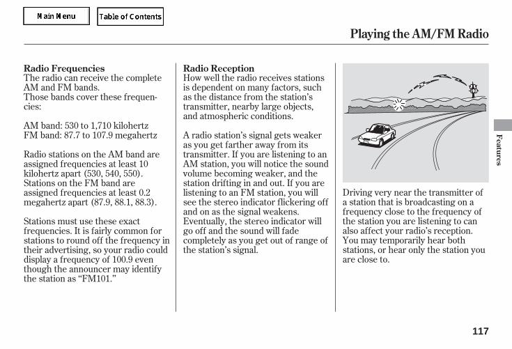
The radio can receive the completeAM and FM bands.Those bands cover these frequen-cies:
AM band: 530 to 1,710 kilohertzFM band: 87.7 to 107.9 megahertz
How well the radio receives stationsis dependent on many factors, suchas the distance from the station’stransmitter, nearby large objects,and atmospheric conditions.
Driving very near the transmitter ofa station that is broadcasting on afrequency close to the frequency ofthe station you are listening to canalso affect your radio’s reception.You may temporarily hear bothstations, or hear only the station youare close to.
A radio station’s signal gets weakeras you get farther away from itstransmitter. If you are listening to anAM station, you will notice the soundvolume becoming weaker, and thestation drifting in and out. If you arelistening to an FM station, you willsee the stereo indicator flickering offand on as the signal weakens.Eventually, the stereo indicator willgo off and the sound will fadecompletely as you get out of range ofthe station’s signal.
Radio stations on the AM band areassigned frequencies at least 10kilohertz apart (530, 540, 550).Stations on the FM band areassigned frequencies at least 0.2megahertz apart (87.9, 88.1, 88.3).
Stations must use these exactfrequencies. It is fairly common forstations to round off the frequency intheir advertising, so your radio coulddisplay a frequency of 100.9 eventhough the announcer may identifythe station as ‘‘FM101.’’
Radio Frequencies Radio Reception
Playing the AM/FM Radio
Features
117
05/09/02 11:49:45 31SDR610 0120
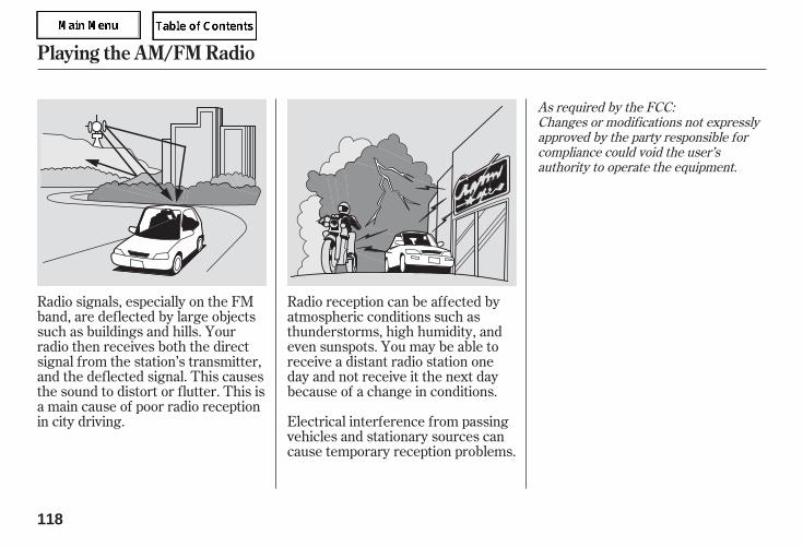
Radio signals, especially on the FMband, are deflected by large objectssuch as buildings and hills. Yourradio then receives both the directsignal from the station’s transmitter,and the deflected signal. This causesthe sound to distort or flutter. This isa main cause of poor radio receptionin city driving.
Radio reception can be affected byatmospheric conditions such asthunderstorms, high humidity, andeven sunspots. You may be able toreceive a distant radio station oneday and not receive it the next daybecause of a change in conditions.
Electrical interference from passingvehicles and stationary sources cancause temporary reception problems.
As required by the FCC:Changes or modifications not expresslyapproved by the party responsible forcompliance could void the user’sauthority to operate the equipment.
Playing the AM/FM Radio
118
05/09/02 11:49:51 31SDR610 0121
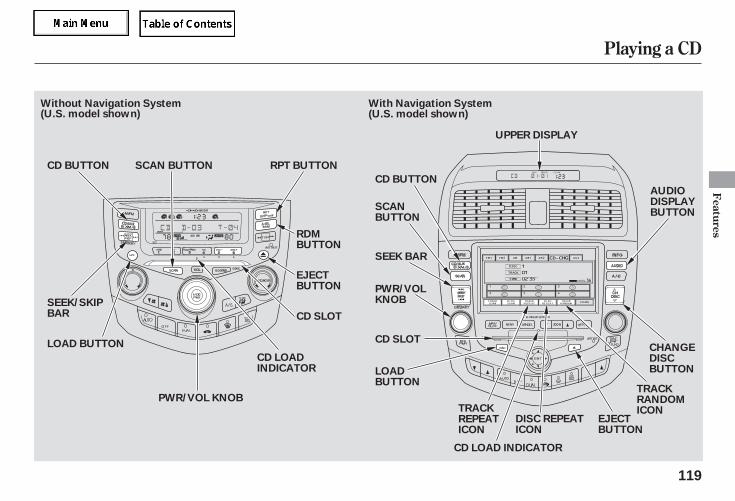
Playing a CD
Features
119
AUDIODISPLAYBUTTON
SEEK/SKIPBAR
CD LOADINDICATOR
CD BUTTON
SEEK BAR
PWR/VOLKNOB
LOADBUTTON
CD SLOT
CD LOAD INDICATOR
LOAD BUTTON
RPT BUTTON
RDMBUTTON
EJECTBUTTON
CD SLOT
PWR/VOL KNOB
CD BUTTON
UPPER DISPLAY
CHANGEDISCBUTTON
Without Navigation System With Navigation System(U.S. model shown)(U.S. model shown)
SCAN BUTTON
SCANBUTTON
TRACKREPEATICON
TRACKRANDOMICON
EJECTBUTTON
DISC REPEATICON
05/09/02 11:49:58 31SDR610 0122
To load or play CDs, the ignitionswitch must be in the ACCESSORY(I) or the ON(II) position.
To listen to satellite radio when a CDis playing, press the CD/AUX XMbutton.
You operate the CD changer withthe same controls used for the radio.To select the CD changer, press theCD button. The numbers of the discand truck playing are shown in thedisplay. On vehicles with navigationsystem, these numbers also appearin the upper display. The system willcontinuously play a disc until youchange modes.
To play the radio when a CD isplaying, press the AM/FM button.Press the CD button again to switchback to the CD player.
To play a tape when a CD is playing,insert a tape in the player (optional).If a tape is in the player, press theCD/AUX button. Press the CD/AUXbutton again to switch back to theCD player.
If you turn the system off while a CDis playing, either with the PWR/VOLknob or by turning off the ignition,the disc will stay in the drive. Whenyou turn the system back on, the CDwill begin playing where it left off.
For vehicles with Satellite RadioTo Play a CD
Playing a CD, CD Changer
120
Do not use discs with adhesive labels.The label can curl up and cause thedisc to jam in the unit.
05/09/02 11:50:05 31SDR610 0123
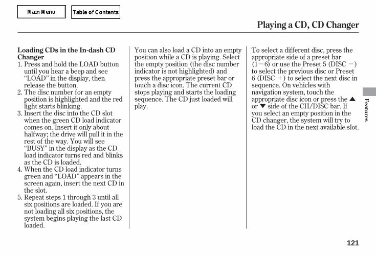
- -
+
▲▼
You can also load a CD into an emptyposition while a CD is playing. Selectthe empty position (the disc numberindicator is not highlighted) andpress the appropriate preset bar ortouch a disc icon. The current CDstops playing and starts the loadingsequence. The CD just loaded willplay.
To select a different disc, press theappropriate side of a preset bar(1 6) or use the Preset 5 (DISC )to select the previous disc or Preset6 (DISC ) to select the next disc insequence. On vehicles withnavigation system, touch theappropriate disc icon or press theor side of the CH/DISC bar. Ifyou select an empty position in theCD changer, the system will try toload the CD in the next available slot.
Repeat steps 1 through 3 until allsix positions are loaded. If you arenot loading all six positions, thesystem begins playing the last CDloaded.
When the CD load indicator turnsgreen and ‘‘LOAD’’ appears in thescreen again, insert the next CD inthe slot.
Insert the disc into the CD slotwhen the green CD load indicatorcomes on. Insert it only abouthalfway; the drive will pull it in therest of the way. You will see‘‘BUSY’’ in the display as the CDload indicator turns red and blinksas the CD is loaded.
The disc number for an emptyposition is highlighted and the redlight starts blinking.
Press and hold the LOAD buttonuntil you hear a beep and see‘‘LOAD’’ in the display, thenrelease the button.
1.
2.
3.
4.
5.
Playing a CD, CD Changer
Loading CDs in the In-dash CDChanger
Features
121
05/09/02 11:50:12 31SDR610 0124
-
-
-
-
-
-
-
-
To use the controls, press theAUDIO DISPLAY button; the controlicons will appear on the screen.
Push the toplay the next track on the disc. Pushthe once to replay the track inplay; press it twice to replay theprevious track. To move rapidlywithin a track, press and hold the
or button.
Press the RPT buttonto continuously replay a track. Youwill see RPT in the display. Press theRPT button again to turn it off.
To continuouslyreplay the current CD, press andhold the RPT button for about asecond. You will see D-RPT in thedisplay. The system switches to thenormal repeat mode when you pressthe RPT button during the discrepeat mode.
Press the RDMbutton to play the tracks in randomorder. You will see RDM in thedisplay. Press the RDM button againto return to normal play.
The SCAN functionsamples all the tracks on theselected disc in the order they arerecorded. To activate it, press andrelease the SCAN button. You willsee SCAN in the display, and you willget a 10 second sampling of eachtrack on the selected CD. Press theSCAN button again to get out of scanmode.
When you press andhold the SCAN button for more than2 seconds, the system gives you a 10second sampling of the first track oneach disc in the in-dash CD changer.You will see D-SCAN in the display.Touch the SCAN button again to getout of disc scan mode.
When youtouch the TRACK REPEAT icon onthe audio display, the systemcontinuously plays the same track.You will see REPEAT beside thetrack information on the audioscreen, and RPT in the upper display.Press the icon again to get out oftrack repeat mode.
When you touchthe DISC REPEAT icon on the audiodisplay, the system continuouslyreplays the current CD. You will seeREPEAT beside the disc informationon the audio screen, and D-RPT inthe upper display. Touch the iconagain to get out of disc repeat mode.
For vehicles without Navigation System For vehicles with Navigation System
Playing a CD, CD Changer
SEEK/SKIP
REPEAT
DISC REPEAT
RANDOM
SCAN
DISC SCAN
TRACK REPEAT
DISC REPEAT
122
05/09/02 11:50:22 31SDR610 0125
- - -When you touchthis icon on the audio display orpress the SCAN button, you will geta 10 second sampling of each trackon the current CD. You will seeSCAN beside the track informationon the audio screen, and SCAN inthe upper display. Press the icon orbutton again to get out of track scanmode.
When you touch theDISC SCAN icon on the audiodisplay, or press and hold the SCANbutton for more than 2 seconds, thesystem gives you a 10 secondsampling of the first track on eachdisc in the in-dash CD changer. Youwill see SCAN beside the discinformation on the audio screen, andD-SCAN in the upper display. Thesystem switches to the track scanmode when you press the SCANbutton. To get out of disc scan mode,touch the icon again, or press andhold the SCAN button for more than2 seconds.
When youtouch the TRACK RANDOM icon onthe audio display, the system playsthe tracks on the current CD inrandom order. You will seeRANDOM beside the trackinformation on the audio screen.Press the icon again to get out oftrack random mode.
Playing a CD, CD Changer
TRACK SCAN DISC SCAN TRACK RANDOM
Features
123
05/09/02 11:50:27 31SDR610 0126
To remove the disc that is currentlyplaying, press the eject button. Youwill see ‘‘EJECT’’ in the display.When you press the eject button, thesystem switches to the previousmode (AM/FM radio, satellite radio(U.S. models), or tape player(optional for U.S. models)).
To remove a different disc from thechanger, first select it with theappropriate preset bar or icon. Whenthat CD begins playing, press theeject button. Continue pressing theEJECT button to remove all the discsfrom the changer.
To remove all the discs in thechanger in a sequence, press andhold the eject button for about 2seconds.
To play a tape when a CD is playing,insert a tape in the player (optional).If a tape is in the player, press theCD/AUX button. Press the CD/AUXbutton again to switch back to theCD player.
If you turn the system off while a CDis playing, the CD will stay in thedrive. When you turn the systemback on, the CD will begin playingwhere it left off.
Press the eject button ( ) toremove the CD. If you eject the CD,but do not remove it from the slot,the system will automatically reloadthe CD after 15 seconds and put it inpause mode. To begin playing, pressthe CD button.
Press the AM/FM or CD/AUX(XM) button to switch to the radio orsatellite radio while a CD is playing.To play the CD, press the CD buttonagain.
Playing a CD, CD Changer
Removing CDs from the ChangerTo Stop Playing a CD
124
05/09/02 11:50:34 31SDR610 0127
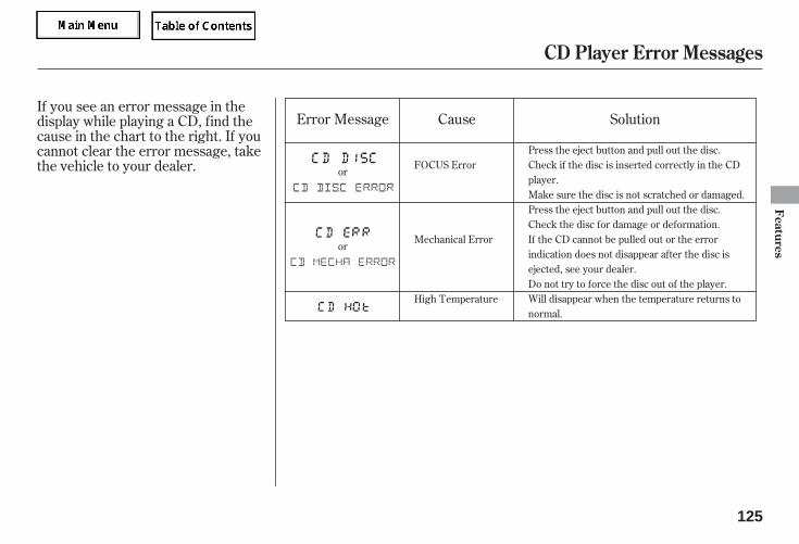
If you see an error message in thedisplay while playing a CD, find thecause in the chart to the right. If youcannot clear the error message, takethe vehicle to your dealer.
Error Message Cause Solution
FOCUS Error
Mechanical Error
High Temperature
Press the eject button and pull out the disc.Check if the disc is inserted correctly in the CDplayer.Make sure the disc is not scratched or damaged.Press the eject button and pull out the disc.Check the disc for damage or deformation.If the CD cannot be pulled out or the errorindication does not disappear after the disc isejected, see your dealer.Do not try to force the disc out of the player.Will disappear when the temperature returns tonormal.
or
or
CD Player Error Messages
Features
125
05/09/02 11:50:41 31SDR610 0128
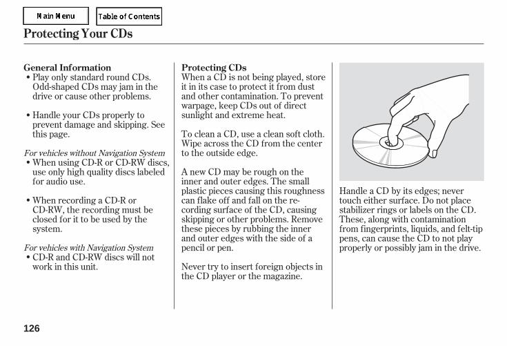
When a CD is not being played, storeit in its case to protect it from dustand other contamination. To preventwarpage, keep CDs out of directsunlight and extreme heat.
To clean a CD, use a clean soft cloth.Wipe across the CD from the centerto the outside edge.
A new CD may be rough on theinner and outer edges. The smallplastic pieces causing this roughnesscan flake off and fall on the re-cording surface of the CD, causingskipping or other problems. Removethese pieces by rubbing the innerand outer edges with the side of apencil or pen.
Never try to insert foreign objects inthe CD player or the magazine.
Play only standard round CDs.Odd-shaped CDs may jam in thedrive or cause other problems.
Handle your CDs properly toprevent damage and skipping. Seethis page.
When using CD-R or CD-RW discs,use only high quality discs labeledfor audio use.
When recording a CD-R orCD-RW, the recording must beclosed for it to be used by thesystem.
CD-R and CD-RW discs will notwork in this unit.
Handle a CD by its edges; nevertouch either surface. Do not placestabilizer rings or labels on the CD.These, along with contaminationfrom fingerprints, liquids, and felt-tippens, can cause the CD to not playproperly or possibly jam in the drive.
For vehicles without Navigation System
For vehicles with Navigation System
General Information Protecting CDs
Protecting Your CDs
126
05/09/02 11:50:51 31SDR610 0129
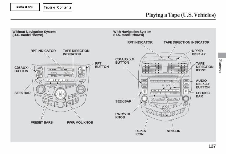
Playing a Tape (U.S. Vehicles)
Features
127
PWR/VOL KNOB
UPPERDISPLAY
AUDIODISPLAYBUTTON
SEEK BAR
CD/AUXBUTTON
SEEK BAR
RPT INDICATOR TAPE DIRECTIONINDICATOR
RPTBUTTON
PWR/VOLKNOB
RPT INDICATOR TAPE DIRECTION INDICATOR
CH/DISCBAR
PRESET BARS
Without Navigation System With Navigation System(U.S. model shown) (U.S. model shown)
REPEATICON
TAPEDIRECTIONICONS
NR ICON
CD/AUX XMBUTTON
05/09/02 11:50:58 31SDR610 0130
*
*
The ignition switch must be in theACCESSORY (I) or ON (II) position.Make sure the open side of the tapeis facing right, then insert the tapemost of the way into the slot. Thesystem will pull the tape in the restof the way, and begin to play it.
Dolby noise reduction turns onwhen you insert a tape. The
indicator will light in thedisplay. If the tape was not recordedin Dolby, turn it off by pressing thePreset 4 (NR) side of the preset baror touching the NR icon. Dolbyremains off until you press thepreset bar or the icon again.
The tape direction indicator willshow you which side of the tape isplaying. If you want to play the otherside, press the Preset 3 (PLAY/PROG) side of the preset bar, orpress the AUDIO DISPLAY buttonand then touch the appropriate tapedirection icon. When the playerreaches the end of the tape, it willautomatically reverse direction andplay the other side.
To remove the tape, press the ejectbutton. If you want to turn the playeroff, press the PWR/VOL knob orturn off the ignition. The tape willremain in the drive. When you turnthe system back on, the tape willbegin playing where it left off.
To switch to the AM/FM radio,Satellite Radio, or CD changer whilea tape is playing, press the AM/FMor CD/AUX (XM) button. To changeback to the tape player, push theCD/AUX (XM) button.
Dolby noise reduction is manufactured underlicense from Dolby Laboratories LicensingCorporation. ‘‘DOLBY’’ and the double-Dsymbol are trademarks of DolbyLaboratories Licensing Corporation.
Optional on all U.S. modelsTo Play a Tape To Stop Playing a Tape
Playing a Tape (U.S. Vehicles)
128
05/09/02 11:51:05 31SDR610 0131
--
-▲
▼
-
Press the side to findthe beginning of the current song orpassage. Press the side to findthe beginning of the next song orpassage. When the system reachesthe beginning of a song or passage, itbegins to play it.
If you see the error message‘‘ ’’ on the display, press thetape eject button to remove the tapefrom the unit. Make sure the tape isnot damaged. If the tape will noteject or the error message stays onafter the tape ejects, take yourvehicle to your dealer.
To rewind the tape,push the preset 1 (REW) side of thepreset bar. You will see REW in thedisplay. To fast forward the tape,push the preset 2 (FF) side of thepreset bar. You will see FF displayed.Press the preset 1, 2, or 3 side of thebars to take the system out of rewindor fast forward.
To fast forward thetape, push the upper side ( ) of theCH/DISC bar, or touch the FF iconon the audio display. You will see FFin the upper display. To rewind thetape, push the lower side ( ) of theCH/DISC bar, or touch the REWicon. You will see REW displayed.Press the bar or touch the icon againto take the system out of rewind orfast forward.
Press the RPT buttonor touch the REPEAT icon on theaudio display to continuously play asong or passage. You will see RPTdisplayed. The track will repeat untilyou press the button or touch theicon again.
The skip and repeatfunctions use silent periods on thetape to find the end of a song orpassage. These features may notwork if there is almost no gapbetween selections, a high noiselevel, or a silent period in the middleof a selection.
For vehicles with Navigation System
For vehicles with Navigation SystemTape Search Functions SKIPFF/REW
FF/REW
REPEAT
Playing a Tape (U.S. Vehicles)
Features
129
NOTE:
05/09/02 11:51:13 31SDR610 0132
If the tape is loose, tighten it byturning the hub with a pencil or yourfinger. If the label is peeling off,remove it or it could cause the tapeto jam in the player. Never try toinsert a warped or damaged tape inthe player.
Store tapes in their cases to protectthem from dust and moisture. Neverplace tapes where they will beexposed to direct sunlight, high heat,or high humidity. If a tape is exposedto extreme heat or cold, let it reach amoderate temperature beforeinserting it into the player.
The tape player picks up dirt andoxides from the tape. Thiscontamination builds up over timeand causes the sound quality todegrade. To prevent this, you shouldclean the player after every 30 hoursof use.
If you do not clean the tape playerregularly, it may eventually becomeimpossible to remove thecontamination with a normalcleaning kit. Your dealer has acleaning kit available.
Use 100-minute or shorter tapes.Tapes longer than that may break orjam the drive.
Never try to insert foreign objectsinto the tape player.
Caring for the Tape and Player
Playing a Tape (U.S. Vehicles)
130
05/09/02 11:51:18 31SDR610 0133
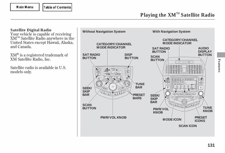
Your vehicle is capable of receivingXM Satellite Radio anywhere in theUnited States except Hawaii, Alaska,and Canada.
XM is a registered trademark ofXM Satellite Radio, Inc.
Satellite radio is available in U.S.models only.
Satellite Digital Radio
Playing the XM Satellite Radio
Features
131
DISPBUTTON
SAT RADIOBUTTON
SCANBUTTON
SCANBUTTON
TUNEKNOB
TUNEBAR
CATEGORY/CHANNELMODE INDICATOR
CATEGORY/CHANNELMODE INDICATOR
PWR/VOLKNOB
SAT RADIOBUTTON
PWR/VOL KNOB
AUDIODISPLAYBUTTON
PRESETBARS
PRESETICONS
Without Navigation System With Navigation System
SEEK/SKIPBAR SEEK/
SKIPBAR
SCAN ICON
MODE ICON
TM
TM
05/09/02 11:51:28 31SDR610 0134
-
-The ignition switch must be in theACCESSORY (I) or the ON (II)position.Turn the system on:
Turn the PWR/VOL knob to adjustthe volume.
Push any of the following: PWR/VOL knob or the CD/AUX XMbutton.
Push any of the following: PWR/VOL knob, the CD/AUX XM, orAUDIO button.
When in the satellite radio mode,you can use any of three methods tofind channels: TUNE, SEEK/SKIP(CATEGORY), and SCAN.
Turn the TUNE knob to changechannels. Turn the knob right forhigher numbered channels and leftfor lower numbered channels.
Press the TUNE bar to changechannel selections. Press forhigher numbered channels and
for lower numbered channels.
Theseek/skip function selects thevarious categories in XM, such asJazz/Blues, Rock, Classical, etc.Push the to change thecategory forward. Push the tochange the category backward. Tosearch for channels within acategory, turn the TUNE knobclockwise or press the TUNE bar
.For vehicles without Navigation System
For vehicles with Navigation SystemFor vehicles with Navigation System
For vehicles without Navigation System
To Play XM Satellite Radio To Select a Channel
TUNE
SEEK/SKIP (CATEGORY)
Playing the XM Satellite Radio
132
TM
TM
05/09/02 11:51:38 31SDR610 0135
- -Once your XM channels are preset,pressing the CH DISC button willselect your preset channels.
The scan function samplesall channels for 5 seconds. Toactivate the function, push the SCANbutton. Push it again to get out of thesequence.
Each preset icon or buttoncan store one channel in XM1 andone in XM2.
Push the CD/AUX XM button.(You will see XM1 or XM2.)Use the TUNE, SEEK or SCANfunction to tune the radio to adesired channel.Pick a preset icon or button andhold it until you hear a beep.Repeat steps 1 to 3 to store a totalof six stations on XM1 and XM2.
1.
2.
3.
4.
For vehicles with Navigation System
Playing the XM Satellite Radio
SCAN Preset
Features
133
TM
05/09/02 11:51:45 31SDR610 0136
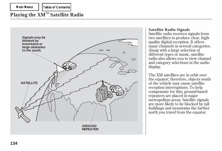
Satellite radio receives signals fromtwo satellites to produce clear, high-quality digital reception. It offersmany channels in several categories.Along with a large selection ofdifferent types of music, satelliteradio also allows you to view channeland category selections in the audiodisplay.
The XM satellites are in orbit overthe equator; therefore, objects southof the vehicle may cause satellitereception interruptions. To helpcompensate for this, ground-basedrepeaters are placed in majormetropolitan areas. Satellite signalsare more likely to be blocked by tallbuildings and mountains the farthernorth you travel from the equator.
Satellite Radio Signals
Playing the XM Satellite Radio
134
SATELLITE
GROUNDREPEATER
Signals may beblocked bymountains orlarge obstaclesto the south.
TM
05/09/02 11:51:50 31SDR610 0137
Depending on where you drive, youmay experience reception problems.Interference can be caused by any ofthese conditions:
Driving on an east/west road witha mountain on the south side ofthe road.
There may be other geographicsituations that could affect satelliteradio reception.
Driving on a single lane roadalongside dense trees taller than50 ft. (15 m) to the south of you.
Driving on the lower level of amulti-tiered road.
Driving on a road beside a verticalwall, steep cliff, or hill to the southof you.
Driving in tunnels.
Driving on the north side of alarge commercial truck on aneast/west road.
If your XM Radio service has expiredor you purchased your vehicle froma previous owner, you can listen to asampling of the broadcasts availableon XM Satellite Radio. With theignition switch in the ACCESSORY(I) or ON (II) position, push thePWR/VOL knob to turn on the audiosystem and press the CD/AUX XMbutton. A variety of music types andstyles will play.
As required by the FCC:Changes or modifications not expresslyapproved by the party responsible forcompliance could void the user’sauthority to operate the equipment.
Receiving Satellite Radio Service
Playing the XM Satellite Radio
Features
135
TM
05/09/02 11:51:58 31SDR610 0138
While awaiting activation, make sureyour vehicle remains in an open areawith good reception. Once youraudio system is activated, ‘‘category’’or ‘‘CH’’ will appear in the displayand you will be able to listen to XMRadio broadcasts. XM Radio willcontinue to send an activation signalto your vehicle for at least 12 hoursfrom activation request. If theservice has not been activated after36 hours, contact XM Radio.
If you decide to purchase XMsatellite radio service, contact XMRadio at , or at1-800-852-9696. You will need to givethem your radio I.D. number andyour credit card number.
Turn the TUNE knob until ‘‘0’’appears in the display. Your I.D. willappear in the display.
After you have registered with XMRadio, keep your audio system in thesatellite radio mode while you waitfor activation. This should take about30 minutes.
www.xmradio.com
To get your XM Satellite radio IDnumber:
Playing the XM Satellite Radio
136
TM
05/09/02 11:52:03 31SDR610 0139
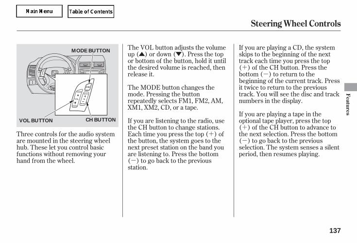
▲ ▼
+-
+
-+
-
The VOL button adjusts the volumeup ( ) or down ( ). Press the topor bottom of the button, hold it untilthe desired volume is reached, thenrelease it.
If you are playing a CD, the systemskips to the beginning of the nexttrack each time you press the top( ) of the CH button. Press thebottom ( ) to return to thebeginning of the current track. Pressit twice to return to the previoustrack. You will see the disc and tracknumbers in the display.
If you are playing a tape in theoptional tape player, press the top( ) of the CH button to advance tothe next selection. Press the bottom( ) to go back to the previousselection. The system senses a silentperiod, then resumes playing.
The MODE button changes themode. Pressing the buttonrepeatedly selects FM1, FM2, AM,XM1, XM2, CD, or a tape.
If you are listening to the radio, usethe CH button to change stations.Each time you press the top ( ) ofthe button, the system goes to thenext preset station on the band youare listening to. Press the bottom( ) to go back to the previousstation.
Three controls for the audio systemare mounted in the steering wheelhub. These let you control basicfunctions without removing yourhand from the wheel.
Steering Wheel Controls
Features
137
CH BUTTONVOL BUTTON
MODE BUTTON
05/09/02 11:52:09 31SDR610 0140
-
If your vehicle’s battery is discon-nected or goes dead, the audiosystem will disable itself. If thishappens, you will see ‘‘CODE’’ in thefrequency display the next time youturn on the system. Use the presetbuttons to enter the five-digit code.The code is on the radio code cardincluded in your owner’s manual kit.When it is entered correctly, theradio will start playing.
If ‘‘0’’ is the first digit in your code,press and release the TUNE knob tostore it.
If your vehicle is equipped with anavigation system, press and releasethe TUNE knob; the number ‘‘0’’appears on the display.
If you make a mistake entering thecode, do not start over; complete thefive-digit sequence, then enter thecorrect code. You have 10 tries toenter the correct code. If you areunsuccessful in 10 attempts, youmust then leave the system on for 1hour before trying again.
If the code card is lost, a dealer canaccess your code with your radio’sserial number. To access the serialnumber, turn the radio on. It mustdisplay ‘‘CODE’’, then turn the radiooff. Push the preset 1, preset 6, andpower buttons at the same time, thenquickly release.
You will have to store your favoritestations on each side of the presetbars (1 6) after the system beginsworking. Your original settings werelost when power was disconnected.
If ‘‘0’’ is not the first digit in yourcode, turn the TUNE knob left orright until the first digit is displayed.Press and release the TUNE knob tostore it. Enter the remaining three
digits the same way.Your vehicle’s audio system willdisable itself if it is disconnectedfrom electrical power for any reason.To make it work again, you mustenter a specific five-digit code usingthe preset bars or the TUNE knob.Because there are hundreds ofnumber combinations possible fromthe five digits, making the systemwork without knowing the exactcode is nearly impossible.
You should have received a card thatlists your audio system code numberand serial number. It is best to storethis card in a safe place at home. Inaddition, you should write the audiosystem’s serial number in this owner’smanual.
If you lose the card, you must obtainthe code number from a dealer. Todo this, you will need the system’sserial number.
Radio Theft Protection
138
05/09/02 11:52:17 31SDR610 0141
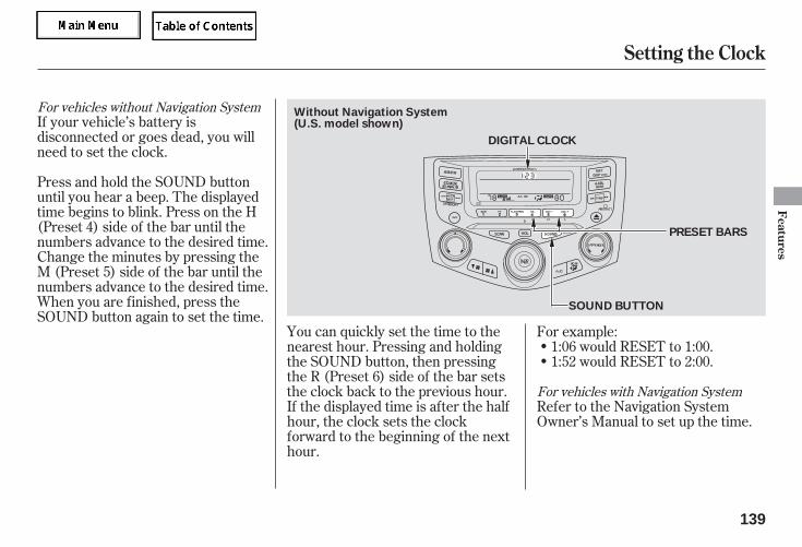
If your vehicle’s battery isdisconnected or goes dead, you willneed to set the clock.
You can quickly set the time to thenearest hour. Pressing and holdingthe SOUND button, then pressingthe R (Preset 6) side of the bar setsthe clock back to the previous hour.If the displayed time is after the halfhour, the clock sets the clockforward to the beginning of the nexthour.
For example:1:06 would RESET to 1:00.1:52 would RESET to 2:00.
Refer to the Navigation SystemOwner’s Manual to set up the time.
Press and hold the SOUND buttonuntil you hear a beep. The displayedtime begins to blink. Press on the H(Preset 4) side of the bar until thenumbers advance to the desired time.Change the minutes by pressing theM (Preset 5) side of the bar until thenumbers advance to the desired time.When you are finished, press theSOUND button again to set the time.
For vehicles without Navigation System
For vehicles with Navigation System
Setting the Clock
Features
139
DIGITAL CLOCK
SOUND BUTTON
PRESET BARS
(U.S. model shown)Without Navigation System
05/09/02 11:52:26 31SDR610 0142
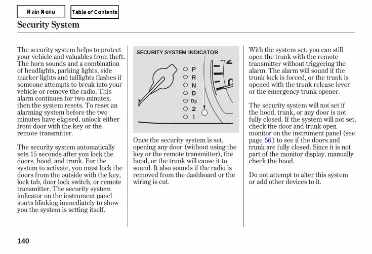
Once the security system is set,opening any door (without using thekey or the remote transmitter), thehood, or the trunk will cause it tosound. It also sounds if the radio isremoved from the dashboard or thewiring is cut.
Do not attempt to alter this systemor add other devices to it.
The security system helps to protectyour vehicle and valuables from theft.The horn sounds and a combinationof headlights, parking lights, sidemarker lights and taillights flashes ifsomeone attempts to break into yourvehicle or remove the radio. Thisalarm continues for two minutes,then the system resets. To reset analarming system before the twominutes have elapsed, unlock eitherfront door with the key or theremote transmitter.
With the system set, you can stillopen the trunk with the remotetransmitter without triggering thealarm. The alarm will sound if thetrunk lock is forced, or the trunk isopened with the trunk release leveror the emergency trunk opener.
The security system will not set ifthe hood, trunk, or any door is notfully closed. If the system will not set,check the door and trunk openmonitor on the instrument panel (seepage ) to see if the doors andtrunk are fully closed. Since it is notpart of the monitor display, manuallycheck the hood.
The security system automaticallysets 15 seconds after you lock thedoors, hood, and trunk. For thesystem to activate, you must lock thedoors from the outside with the key,lock tab, door lock switch, or remotetransmitter. The security systemindicator on the instrument panelstarts blinking immediately to showyou the system is setting itself.
56
Security System
140
SECURITY SYSTEM INDICATOR
05/09/02 11:52:32 31SDR610 0143
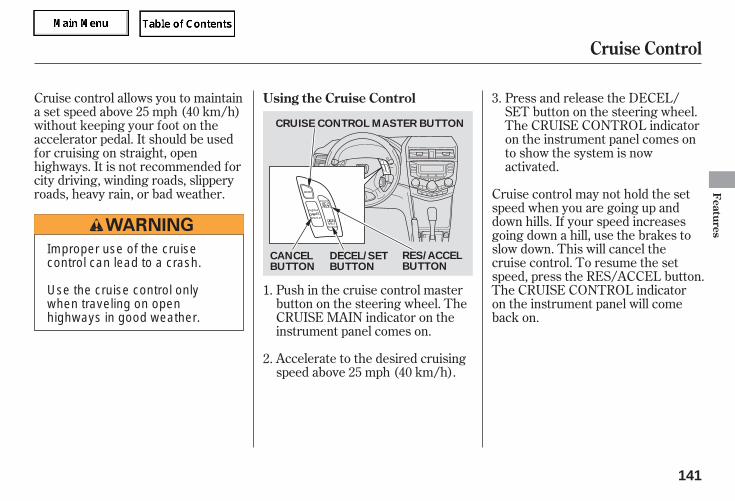
Accelerate to the desired cruisingspeed above 25 mph (40 km/h).
Cruise control allows you to maintaina set speed above 25 mph (40 km/h)without keeping your foot on theaccelerator pedal. It should be usedfor cruising on straight, openhighways. It is not recommended forcity driving, winding roads, slipperyroads, heavy rain, or bad weather.
Push in the cruise control masterbutton on the steering wheel. TheCRUISE MAIN indicator on theinstrument panel comes on.
Press and release the DECEL/SET button on the steering wheel.The CRUISE CONTROL indicatoron the instrument panel comes onto show the system is nowactivated.
Cruise control may not hold the setspeed when you are going up anddown hills. If your speed increasesgoing down a hill, use the brakes toslow down. This will cancel thecruise control. To resume the setspeed, press the RES/ACCEL button.The CRUISE CONTROL indicatoron the instrument panel will comeback on.
1.
2.
3.Using the Cruise Control
Cruise Control
Features
141
CRUISE CONTROL MASTER BUTTON
CANCELBUTTON
RES/ACCELBUTTON
DECEL/SETBUTTON
Improper use of the cruisecontrol can lead to a crash.
Use the cruise control onlywhen traveling on openhighways in good weather.
05/09/02 11:52:39 31SDR610 0144
You can increase the set cruisingspeed in any of these ways:
Press and hold the RES/ACCELbutton. When you reach thedesired cruising speed, release thebutton.
Push on the accelerator pedal.Accelerate to the desired cruisingspeed, and press the DECEL/SETbutton.
To increase the speed in verysmall amounts, tap the RES/ACCEL button. Each time you dothis, your vehicle will speed upabout 1 mph (1.6 km/h).
You can decrease the set cruisingspeed in any of these ways:
Press and hold the DECEL/SETbutton. Release the button whenyou reach the desired speed.
To slow down in very smallamounts, tap the DECEL/SETbutton repeatedly. Each time youdo this, your vehicle will slowdown about 1 mph (1.6 km/h).
Tap the brake pedal lightly withyour foot. The CRUISECONTROL indicator on theinstrument panel will go out.When the vehicle slows to thedesired speed, press the DECEL/SET button.
Even with the cruise control turnedon, you can still use the acceleratorpedal to speed up for passing. Aftercompleting the pass, take your footoff the accelerator pedal. The vehiclewill return to the set cruising speed.
Resting your foot on the brake pedalcauses cruise control to cancel.
Cruise Control
Changing the Set Speed
142
05/09/02 11:52:47 31SDR610 0145
You can cancel cruise control in anyof these ways:
Push the CANCEL button on thesteering wheel.
Push the cruise control masterbutton.
Tap the brake pedal.
When you push the CANCEL button,or tap the brake pedal, the systemwill remember the previously-setcruising speed. To return to thatspeed, accelerate to above 25 mph(40 km/h) and then press andrelease the RES/ACCEL button. TheCRUISE CONTROL indicator comeson. The vehicle will accelerate to thesame cruising speed as before.
Pressing the cruise control masterbutton turns the system completelyoff and erases the previous cruisingspeed.
Canceling Cruise Control Resuming the Set Speed
Cruise Control
Features
143
05/09/02 11:52:54 31SDR610 0146
-
To do this, press and hold the twooutside buttons on the HomeLinktransceiver for about 20 seconds,until the red indicator flashes.Release the buttons, then proceed tostep 1.
If you justreceived your vehicle and have nottrained any of the buttons inHomeLink before, you should eraseany previously learned codes beforetraining the first button.
If you are training the second orthird buttons, go directly to step 1.
Unplug the garage door openermotor from the electrical outlet.
Hold the end of the garage dooropener remote 2 to 5 inches fromHomeLink. Make sure you are notblocking your view of the redindicator in HomeLink.
The HomeLink universaltransceiver built into your vehiclecan be programmed to operate up tothree remotely controlled devicesaround your home, such as garagedoors, lighting, or home securitysystems.
If you are training HomeLink tooperate a garage door or gate, youshould unplug the motor for thatdevice during training. Repeatedlypressing the remote control buttoncould burn out the motor.
HomeLink stores the code in apermanent memory. There shouldbe no need to retrain HomeLink ifyour vehicle’s battery goes dead or isdisconnected. If your garage dooropener was manufactured beforeApril 1982, you may not be able toprogram HomeLink to operate it.They do not have the safety featurethat causes the motor to stop and
reverse if an obstacle is detectedduring closing, increasing the risk ofinjury.
Always refer to the openinginstructions and safety informationthat came with your garage dooropener or other equipment youintend to operate with HomeLink. Ifyou do not have this information,contact the manufacturer of theequipment.
For quick and accurate training,make sure the remote controltransmitter for the device (garagedoor, automatic gate, securitysystem, etc.) has a fresh battery.
1.
2.
Training HomeLink
General Information
Important Safety Precautions
Before you begin
HomeLink Universal Transceiver
144
05/09/02 11:53:04 31SDR610 0147
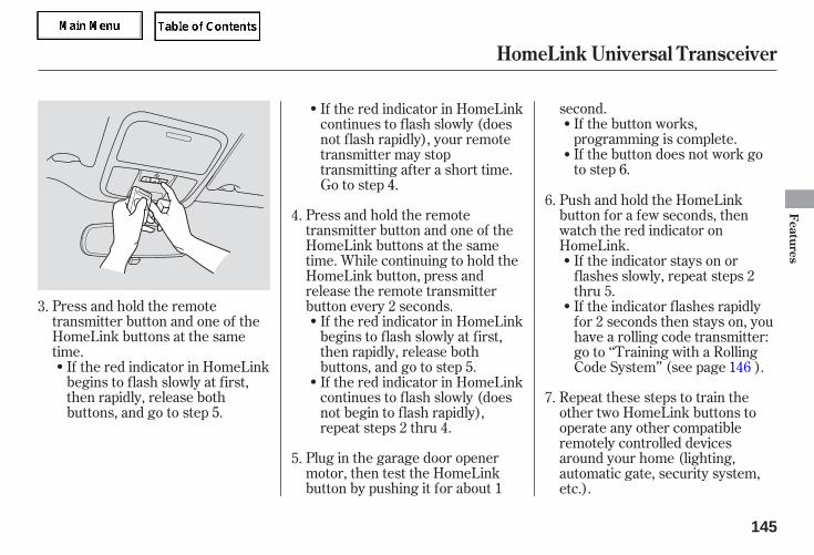
Plug in the garage door openermotor, then test the HomeLinkbutton by pushing it for about 1
second.If the button works,programming is complete.If the button does not work goto step 6.
Press and hold the remotetransmitter button and one of theHomeLink buttons at the sametime.
If the red indicator in HomeLinkbegins to flash slowly at first,then rapidly, release bothbuttons, and go to step 5.
Press and hold the remotetransmitter button and one of theHomeLink buttons at the sametime. While continuing to hold theHomeLink button, press andrelease the remote transmitterbutton every 2 seconds.
If the red indicator in HomeLinkbegins to flash slowly at first,then rapidly, release bothbuttons, and go to step 5.If the red indicator in HomeLinkcontinues to flash slowly (doesnot begin to flash rapidly),repeat steps 2 thru 4.
Repeat these steps to train theother two HomeLink buttons tooperate any other compatibleremotely controlled devicesaround your home (lighting,automatic gate, security system,etc.).
If the indicator stays on orflashes slowly, repeat steps 2thru 5.
Push and hold the HomeLinkbutton for a few seconds, thenwatch the red indicator onHomeLink.
If the red indicator in HomeLinkcontinues to flash slowly (doesnot flash rapidly), your remotetransmitter may stoptransmitting after a short time.Go to step 4.
If the indicator flashes rapidlyfor 2 seconds then stays on, youhave a rolling code transmitter:go to ‘‘Training with a RollingCode System’’ (see page ).
3.
4.
5.
6.
7.
146
HomeLink Universal Transceiver
Features
145
05/09/02 11:53:15 31SDR610 0148
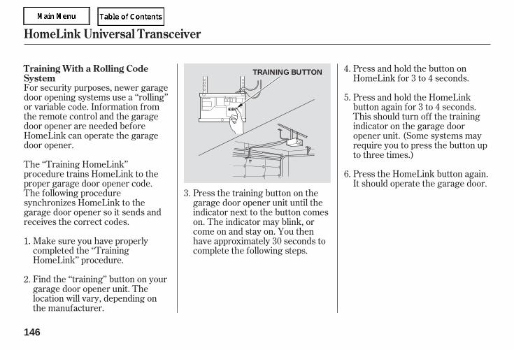
For security purposes, newer garagedoor opening systems use a ‘‘rolling’’or variable code. Information fromthe remote control and the garagedoor opener are needed beforeHomeLink can operate the garagedoor opener.
Find the ‘‘training’’ button on yourgarage door opener unit. Thelocation will vary, depending onthe manufacturer.
Make sure you have properlycompleted the ‘‘TrainingHomeLink’’ procedure.
Press the HomeLink button again.It should operate the garage door.
The ‘‘Training HomeLink’’procedure trains HomeLink to theproper garage door opener code.The following proceduresynchronizes HomeLink to thegarage door opener so it sends andreceives the correct codes.
Press the training button on thegarage door opener unit until theindicator next to the button comeson. The indicator may blink, orcome on and stay on. You thenhave approximately 30 seconds tocomplete the following steps.
Press and hold the button onHomeLink for 3 to 4 seconds.
Press and hold the HomeLinkbutton again for 3 to 4 seconds.This should turn off the trainingindicator on the garage dooropener unit. (Some systems mayrequire you to press the button upto three times.)
6.
2.
4.
5.
1.
3.
Training With a Rolling CodeSystem
HomeLink Universal Transceiver
146
TRAINING BUTTON
05/09/02 11:53:23 31SDR610 0149
You should erase all three codesbefore selling the vehicle.
To erase the codes stored in all threebuttons, press and hold the twooutside buttons until the redindicator begins to flash, thenrelease the buttons.
If you want to retrain a programmedbutton for a new device, you do nothave to erase all button memory.You can replace the existing memorycode using this procedure:
If a standard transmitter wasprogrammed, the indicator willstay on for about 25 seconds.
HomeLink is a registeredtrademark of Johnson Controls, Inc.
If you have problems with trainingthe HomeLink Universal Transceiver,or would like information on homeproducts that can be operated byHomeLink, call (800) 355-3515. Onthe Internet, go towww.homelink.com.
Once the HomeLink indicatorbegins to flash slowly, continue tohold the HomeLink button, andfollow steps 3 thru 6 under‘‘Training HomeLink’’ (see page
).
If a rolling code transmitter waspreviously programmed, theindicator will flash rapidly for 2seconds, and then stay on forabout 23 seconds.
Press and hold the HomeLinkbutton to be trained until theHomeLink indicator begins toflash slowly.
1.
2.
144
As required by the FCC:This device complies with Part 15 of theFCC rules. Operation is subject to thefollowing two conditions: (1) This devicemay not cause harmful interference, and(2) this device must accept anyinterference received, includinginterference that may cause undesiredoperation.
Changes or modifications not expresslyapproved by the party responsible forcompliance could void the user’sauthority to operate the equipment.
This device complies with IndustryCanada Standard RSS-210.Operation is subject to the following twoconditions: (1) this device may not causeinterference, and (2) this device mustaccept any interference that may causeundesired operation of the device.
Erasing Codes
Retraining a ButtonCustomer Assistance
HomeLink Universal Transceiver
Features
147
05/09/02 11:53:34 31SDR610 0150

Before you begin driving yourvehicle, you should know whatgasoline to use and how to check thelevels of important fluids. You alsoneed to know how to properly storeluggage or packages. Theinformation in this section will helpyou. If you plan to add anyaccessories to your vehicle, pleaseread the information in this sectionfirst.
.............................Break-in Period . 150.................Fuel Recommendation . 150
.........Service Station Procedures . 151....................................Refueling . 151
Opening and Closing the.......................................Hood . 152
...................................Oil Check . 153.............Engine Coolant Check . 154
...............................Fuel Economy . 155........Improving Fuel Economy . 155
...Accessories and Modifications . 156................................Accessories . 156
...........Modifying Your Vehicle . 157.Additional Safety Precautions . 157
.............................Carrying Cargo . 158................................Load Limits . 159
Carrying Cargo in the Trunk.................or on a Roof Rack . 160
Carrying Cargo in the.....Passenger Compartment . 160
Before Driving
Before
Driving
149
05/09/02 11:53:41 31SDR610 0152
Help assure your vehicle’s futurereliability and performance by payingextra attention to how you driveduring the first 600 miles (1,000 km).During this period:
Avoid full-throttle starts and rapidacceleration.
Do not change the oil until thescheduled maintenance time.
Avoid hard braking for the first200 miles (300 km).
Do not tow a trailer.
You should also follow theserecommendations with anoverhauled or exchanged engine, orwhen the brakes are replaced.
Your vehicle is designed to operateon unleaded gasoline with a pumpoctane number of 87 or higher. Useof a lower octane gasoline can causea persistent, heavy metallic rappingnoise that can lead to engine damage.
We recommend quality gasolinecontaining detergent additives thathelp prevent fuel system and enginedeposits.
In addition, in order to maintain goodperformance, fuel economy, andemissions control, we stronglyrecommend, in areas where it isavailable, the use of gasoline thatdoes NOT contain manganese-basedfuel additives such as MMT.
Use of gasoline with these additivesmay adversely affect performance,and cause the malfunction indicatorlamp on your instrument panel tocome on. If this happens, contact
your authorized dealer for service.
Some gasoline today is blended withoxygenates such as ethanol orMTBE. Your vehicle is designed tooperate on oxygenated gasolinecontaining up to 10 percent ethanolby volume and up to 15 percentMTBE by volume. Do not usegasoline containing methanol.
If you notice any undesirableoperating symptoms, try anotherservice station or switch to anotherbrand of gasoline.
For further important fuel-relatedinformation, please refer to your
.
Break-in Period, Fuel Recommendation
Break-in Period Fuel Recommendation
Quick Start Guide
150
05/09/02 11:53:51 31SDR610 0153
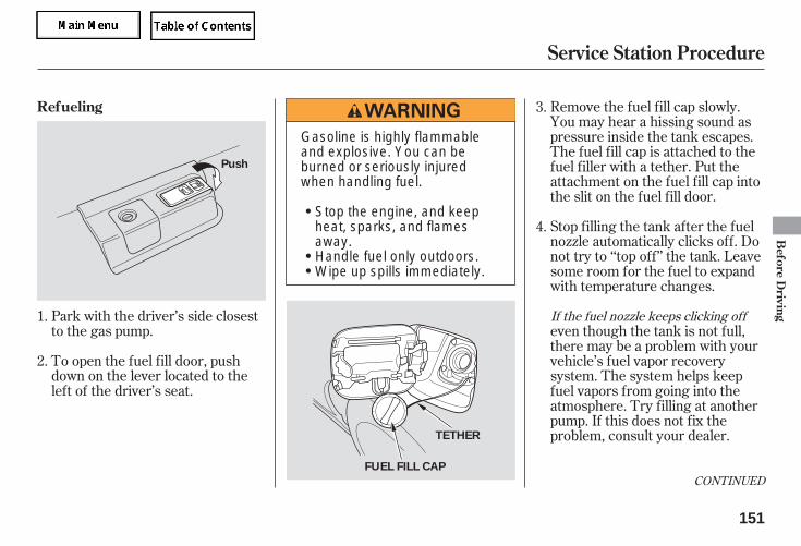
Remove the fuel fill cap slowly.You may hear a hissing sound aspressure inside the tank escapes.The fuel fill cap is attached to thefuel filler with a tether. Put theattachment on the fuel fill cap intothe slit on the fuel fill door.
Stop filling the tank after the fuelnozzle automatically clicks off. Donot try to ‘‘top off’’ the tank. Leavesome room for the fuel to expandwith temperature changes.
Park with the driver’s side closestto the gas pump.
To open the fuel fill door, pushdown on the lever located to theleft of the driver’s seat.
even though the tank is not full,there may be a problem with yourvehicle’s fuel vapor recoverysystem. The system helps keepfuel vapors from going into theatmosphere. Try filling at anotherpump. If this does not fix theproblem, consult your dealer.
3.
4.
1.
2.
If the fuel nozzle keeps clicking off
CONTINUED
Refueling
Service Station Procedure
Before
Driving
151
FUEL FILL CAP
Push
TETHER
Gasoline is highly flammableand explosive. You can beburned or seriously injuredwhen handling fuel.
Stop the engine, and keepheat, sparks, and flamesaway.Handle fuel only outdoors.Wipe up spills immediately.
05/09/02 11:54:01 31SDR610 0154
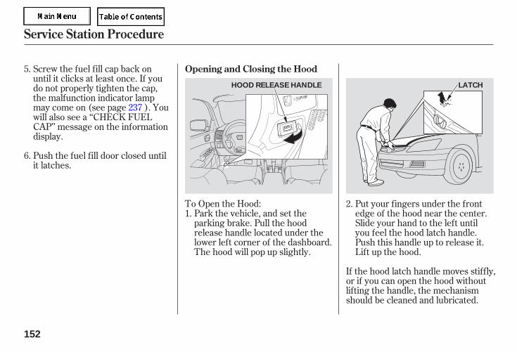
To Open the Hood:Park the vehicle, and set theparking brake. Pull the hoodrelease handle located under thelower left corner of the dashboard.The hood will pop up slightly.
Put your fingers under the frontedge of the hood near the center.Slide your hand to the left untilyou feel the hood latch handle.Push this handle up to release it.Lift up the hood.
If the hood latch handle moves stiffly,or if you can open the hood withoutlifting the handle, the mechanismshould be cleaned and lubricated.
Push the fuel fill door closed untilit latches.
Screw the fuel fill cap back onuntil it clicks at least once. If youdo not properly tighten the cap,the malfunction indicator lampmay come on (see page ). Youwill also see a ‘‘CHECK FUELCAP’’ message on the informationdisplay.
1.2.
5.
6.
237
Opening and Closing the Hood
Service Station Procedure
152
HOOD RELEASE HANDLE LATCH
05/09/02 11:54:09 31SDR610 0155
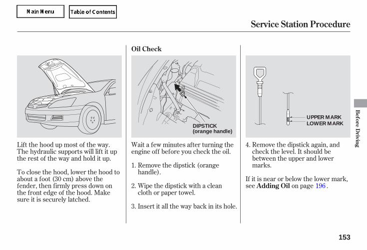
Remove the dipstick again, andcheck the level. It should bebetween the upper and lowermarks.
If it is near or below the lower mark,see on page .
Insert it all the way back in its hole.
Wipe the dipstick with a cleancloth or paper towel.
Remove the dipstick (orangehandle).
Wait a few minutes after turning theengine off before you check the oil.
Lift the hood up most of the way.The hydraulic supports will lift it upthe rest of the way and hold it up.
To close the hood, lower the hood toabout a foot (30 cm) above thefender, then firmly press down onthe front edge of the hood. Makesure it is securely latched.
1.
2.
3.
4.
196Adding Oil
Oil Check
Service Station Procedure
Before
Driving
153
DIPSTICK(orange handle)
UPPER MARK
LOWER MARK
05/09/02 11:54:18 31SDR610 0156

Look at the coolant level in theradiator reserve tank. Make sure it isbetween the MAX and MIN lines. Ifit is below the MIN line, see
on page forinformation on adding the propercoolant.
Refer toon page for information
about checking other items on yourvehicle.
201
191Engine Coolant Check
AddingEngine Coolant
Owner’s MaintenanceChecks
Service Station Procedure
154
MAX RESERVE TANK
MIN
05/09/02 11:54:24 31SDR610 0157
Always drive in the highest gearpossible.
Try to maintain a constant speed.Every time you slow down andspeed up, your vehicle uses extrafuel. Use cruise control whenappropriate.
Combine several short trips intoone.
The air conditioning puts an extraload on the engine which makes ituse more fuel. Use the fresh-airventilation when possible.
Drive moderately. Rapidacceleration, abrupt cornering,and hard braking use more fuel.
The build-up of snow or mud onyour vehicle’s underside addsweight and rolling resistance.Frequent cleaning helps your fuelmileage and reduces the chance ofcorrosion.
an underinflated tirecauses more ‘‘rolling resistance,’’which uses more fuel.
Always maintain your vehicleaccording to the maintenanceminder. See
(see page).191
For example,
Improving Fuel Economy
Owner’sMaintenance Checks
Fuel Economy
Before
Driving
155
05/09/02 11:54:31 31SDR610 0158
Before installing any accessory:
Make sure the accessory does notobscure any lights, or interferewith proper vehicle operation orperformance.
When properly installed, cellularphones, alarms, two-way radios, andlow-powered audio systems shouldnot interfere with your vehicle’scomputer controlled systems, suchas your airbags and anti-lock brakes.
Modifying your vehicle, or installingsome non-Honda accessories, canmake your vehicle unsafe. Beforeyou make any modifications or addany accessories, be sure to read thefollowing information.
Your dealer has Honda accessoriesthat allow you to personalize yourvehicle. These accessories havebeen designed and approved for yourvehicle, and are covered by warranty. Before installing any electronic
accessory, have the installercontact your dealer for assistance.If possible, have your dealerinspect the final installation.
Do not install accessories on theside pillars or across the rearwindows. In these areas,accessories may interfere withproper operation of the sidecurtain airbags.
Although non-Honda accessoriesmay fit on your vehicle, they may notmeet factory specifications, andcould adversely affect your vehicle’shandling and stability.
Be sure electronic accessories donot overload electrical circuits(see page ) or interfere withproper operation of your vehicle.
243
Accessories
Accessories and Modifications
156
Improper accessories ormodifications can affect yourvehicle’s handling, stability, andperformance, and cause acrash in which you can be hurtor killed.
Follow all instructions in thisowner’s manual regardingaccessories and modifications.
05/09/02 11:54:39 31SDR610 0159
Removing parts from your vehicle,or replacing components withaftermarket components couldseriously affect your vehicle’shandling, stability, and reliability.
Some examples are:
Larger or smaller wheels and tirescan interfere with the operation ofyour vehicle’s anti-lock brakes andother systems.
If you plan to modify your vehicle,consult your dealer.
Modifying your steering wheel orany other part of your vehicle’ssafety features can make thesystems ineffective.Lowering the vehicle with a non-
Honda suspension kit thatsignificantly reduces groundclearance can allow theundercarriage to hit speed bumpsor other raised objects, whichcould cause the airbags to deploy.
Raising your vehicle with anon-Honda suspension kit canaffect the handling and stability.
Non-Honda wheels can causeexcessive stress on suspensioncomponents.
If a side airbagor a side curtain airbag inflates, acup holder or other hard objectattached on or near the door couldbe propelled inside the vehicle andhurt someone.
Covering the outside edge of afront seat-back, with a non-Hondaseat cover for example, couldprevent the airbag from inflatingproperly.
Any objectattached to or placed on the coversmarked ‘‘SRS AIRBAG’’ in thecenter of the steering wheel andon top of the dashboard, couldinterfere with the proper operationof the airbags. Or, if the airbagsinflate, the objects could bepropelled inside the vehicle andhurt someone.
Modifying Your Vehicle
Additional Safety Precautions
Accessories and Modifications
Do not attach hard objects on ornear a front door.
Do not place any objects over theoutside edge of a front seat-back.
Do not attach or place objects onthe front airbag covers.
Before
Driving
157
05/09/02 11:54:49 31SDR610 0160
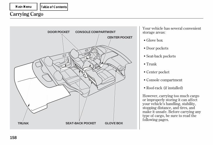
Your vehicle has several convenientstorage areas:
Glove box
Roof-rack (if installed)
Console compartment
Center pocket
Trunk
Door pockets
Seat-back pockets
However, carrying too much cargoor improperly storing it can affectyour vehicle’s handling, stability,stopping distance, and tires, andmake it unsafe. Before carrying anytype of cargo, be sure to read thefollowing pages.
Carrying Cargo
158
GLOVE BOXSEAT-BACK POCKETTRUNK
DOOR POCKET CONSOLE COMPARTMENT
CENTER POCKET
05/09/02 11:54:57 31SDR610 0161
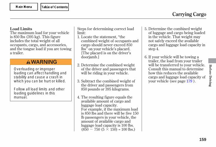
- ×
The maximum load for your vehicleis 850 lbs (395 kg). This figureincludes the total weight of alloccupants, cargo, and accessories,and the tongue load if you are towinga trailer.
Determine the combined weightof luggage and cargo being loadedin the vehicle. That weight maynot safely exceed the availablecargo and luggage load capacity instep 4.
If your vehicle will be towing atrailer, the load from your trailerwill be transferred to your vehicle.Consult this manual to determinehow this reduces the availablecargo and luggage load capacity ofyour vehicle (see page ).
The resulting figure equals theavailable amount of cargo andluggage load capacity.For example, if the maximum loadis 850 lbs and there will be five 150lb passengers in your vehicle, theamount of available cargo andluggage load capacity is 100 lbs.(850 750 (5 150) = 100 lbs.)
Subtract the combined weight ofthe driver and passengers from850 pounds or 395 kilograms.
Determine the combined weightof the driver and passengers thatwill be riding in your vehicle.
Locate the statement, ‘‘thecombined weight of occupants andcargo should never exceed 850lbs’’ on your vehicle’s placard.[The placard is on the driver’sdoorjamb.]
Steps for determining correct loadlimit:1.
2.
5.
6.
3.
4.
179
Load Limits
Carrying Cargo
Before
Driving
159
Overloading or improperloading can affect handling andstability and cause a crash inwhich you can be hurt or killed.
Follow all load limits and otherloading guidelines in thismanual.
05/09/02 11:55:06 31SDR610 0162
Store or secure all items that couldbe thrown around and hurtsomeone during a crash.
If you carry large items thatprevent you from closing the trunklid, exhaust gas can enter thepassenger area. To avoid thepossibility of
, follow the instructionson page .
If you carry any items on a roofrack, be sure the total weight ofthe rack and the items does notexceed 165 lbs (75 kg).
If you use an accessory roof rack,the roof rack weight limit may belower. Refer to the information thatcame with your roof rack.
In addition, the total weight of thevehicle, all passengers andaccessories must not exceed theGross Vehicle Weight Rating(GVWR) or the Gross Axle WeightRating (GAWR). Both are on a labelon the driver’s doorjamb.
Distribute cargo evenly on thefloor of the trunk, placing theheaviest items on the bottom andas far forward as possible. Tiedown items that could be thrownabout the vehicle during a crash orsudden stop.
Do not put any items on top of therear shelf. They can block yourview and be thrown around thevehicle during a crash.
Be sure items placed on the floorbehind the front seats cannot rollunder the seats and interfere withthe driver’s ability to operate thepedals or the seat.
Keep the glove box closed whiledriving so that someone in thepassenger seat can avoid injuriesto their knees in a crash or asudden stop.
Do not store any perishable itemsnear the IMA battery vent (seepage ).
Do not put any objects on the IMAbattery air intake on the rear shelf(see page ).
49
161
161
carbon monoxidepoisoning
Carrying Cargo in the Trunk or ona Roof Rack
Carrying Cargo in the PassengerCompartment
Carrying Cargo
160
05/09/02 11:55:15 31SDR610 0163

Do not spill any liquids over the airintake or put any small foreignobjects in it. This may damage theIMA battery and the power controlunit.
Air used to cool the IMA battery isvented into the right side of thetrunk. Do not leave perishable itemsnear this vent.
The air intake for the IMA batteryand electronics is located on top ofthe rear shelf. Do not block this airintake; it may cause the IMA batteryand the power control unit tooverheat, causing the IMA system toshut down. It will start working againafter it cools.
Carrying Cargo
IMA Battery Air Intake IMA Battery Air Vent
Before
Driving
161
AIR INTAKE AIR VENT
05/09/02 11:55:22 31SDR610 0164

........................Preparing to Drive . 164.......................Starting the Engine . 165
..............Automatic Transmission . 166Shift Lever Position
...............................Indicators . 166.......................................Shifting . 166
..............Engine Speed Limiter . 168....................Shift Lock Release . 169
............................Auto Idle Stop . 171...........Auto Idle Stop Indicator . 172
...........................................Parking . 173.............................Braking System . 174
...............Brake System Design . 174.............Brake Wear Indicators . 174...........Anti-lock Brakes (ABS) . 175
Activating the Anti-lock................................Brakes . 175
........................ABS Indicator . 175Vehicle Stability Assist (VSA)
....................................System . 177.........VSA Activation Indicator . 177
..............VSA System Indicator . 177.........................VSA Off Switch . 178
...........................Towing a Trailer . 179
This section gives you tips onstarting the engine under variousconditions, and how to operate theautomatic transmission. It alsoincludes important information onparking your vehicle, the brakingsystem, the vehicle stability assist(VSA) system, and facts you need ifyou are planning to tow a trailer.
Driving
Driving
163
05/09/02 11:55:28 31SDR610 0166
You should do the following checksand adjustments before you driveyour vehicle.
Make sure all windows, mirrors,and outside lights are clean andunobstructed. Remove frost, snow,or ice.
Make sure the doors are securelyclosed and locked.
Fasten your seat belt. Check thatyour passengers have fastenedtheir seat belts (see page ).
Check the steering wheeladjustment (see page ).
Check that the hood is fully closed.
Check that the trunk is fullyclosed.
Visually check the tires. If a tirelooks low, use a gauge to check itspressure.
Check that any items you may becarrying are stored properly orfastened down securely.
Check the seat adjustment (seepages to ).
Check the adjustment of theinside and outside mirrors (seepages and ).
When you start the engine, checkthe gauges and indicators in theinstrument panel (see pages to
).
3.
2.
1.
4.
5.
6.
7.
8.
9.
11.
10.
16
85 87
88 89
75
6853
Preparing to Drive
164
05/09/02 11:55:38 31SDR610 0167
Apply the parking brake.
In cold weather, turn off allelectrical accessories to reducethe drain on the battery.
Make sure the shift lever is inPark. Press on the brake pedal.
Turn the ignition key to theSTART (III) position. Do not holdthe key in START (III) for morethan 15 seconds at a time. If theengine does not start right away,pause for at least 10 secondsbefore trying again.
If the engine does not start within15 seconds, or starts but stallsright away, repeat step 4 with theaccelerator pedal pressed halfwaydown. If the engine starts, releasepressure on the accelerator pedalso the engine does not race.
If the engine fails to start, pressthe accelerator pedal all the waydown and hold it there whilestarting to clear flooding. Returnto step 5 if the engine does notstart.
In cold weather, conventional starteris used instead of the IMA systemstarter. This is normal.
1.
2.
3.
4.5.
6.
77
Starting the Engine
Starting in Cold Weather
Driving
165
The immobilizer system protects yourvehicle f rom thef t. If an improperly-coded key (or other device) is used, theengine’s f uel system is disabled. Formore inf ormation, see page .
The engine is harder to start in coldweather. Also, the thinner air f ound ataltitudes above 8,000 f eet (2,400meters) adds to this problem.
05/09/02 11:55:46 31SDR610 0168
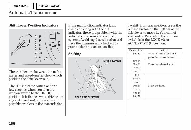
These indicators between the tacho-meter and speedometer show whichposition the shift lever is in.
The ‘‘D’’ indicator comes on for afew seconds when you turn theignition switch to the ON (II)position. If it flashes while driving (inany shift position), it indicates apossible problem in the transmission.
If the malfunction indicator lampcomes on along with the ‘‘D’’indicator, there is a problem with theautomatic transmission controlsystem. Avoid rapid acceleration andhave the transmission checked byyour dealer as soon as possible.
To shift from any position, press therelease button on the bottom of theshift lever to move it. You cannotshift out of Park when the ignitionswitch is in the LOCK (0) orACCESSORY (I) position.
To shift from:P to R
R to PN to RD to 22 to 11 to 2
2 to DD to DD to ND to DN to DR to N
Do this:Press the brake pedal andpress the release button.
Press the release button.
Move the lever.
3
3
3
3
Automatic Transmission
Shift Lever Position Indicators
Shifting
166
SHIFT LEVER
RELEASE BUTTON
05/09/02 11:55:55 31SDR610 0169

- -
-
-
-
If you have done all of the above andstill cannot move the lever out ofPark, see onpage .
You must also press the releasebutton to shift into Park. To avoidtransmission damage, come to acomplete stop before shifting intoPark. The shift lever must be in Parkbefore you can remove the key fromthe ignition switch.
Press the brakepedal and press the release button toshift from Park to Reverse. To shiftfrom Reverse to Neutral, come to acomplete stop and then shift.
This position is similarto D, except only the first threegears are selected instead of all five.Use D when towing a trailer in hillyterrain, or to provide engine brakingwhen going down a steep hill. D canalso keep the transmission fromcycling between third and fourthgears in stop-and-go driving.
Use this position foryour normal driving. Thetransmission automatically selects asuitable gear for the vehicle speedand acceleration. You may notice thetransmission shifting up at higherspeeds when the engine is cold. Thishelps the engine warm up faster.
Use Neutral if youneed to restart a stalled engine, or ifit is necessary to stop briefly withthe engine idling. Shift to the Parkposition if you need to leave yourvehicle and apply the parking brake.Press on the brake pedal when youare moving the shift lever fromNeutral to another gear.
This positionmechanically locks the transmission.Use Park whenever you are turningoff or starting the engine. To shiftout of Park, you must press on thebrake pedal and have your foot offthe accelerator pedal. Press therelease button on the bottom of theshift lever to move it.
169
3
3
CONTINUED
Automatic Transmission
Shift Lock Release
Reverse (R) Drive (D )
Drive (D)
Neutral (N)
Park (P) 3
Driving
167
05/09/02 11:56:01 31SDR610 0170
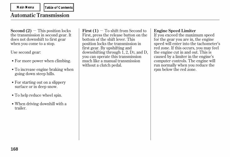
- -This position locksthe transmission in second gear. Itdoes not downshift to first gearwhen you come to a stop.
Use second gear:
For starting out on a slipperysurface or in deep snow.
To help reduce wheel spin.
When driving downhill with atrailer.
If you exceed the maximum speedfor the gear you are in, the enginespeed will enter into the tachometer’sred zone. If this occurs, you may feelthe engine cut in and out. This iscaused by a limiter in the engine’scomputer controls. The engine willrun normally when you reduce therpm below the red zone.
For more power when climbing.
To increase engine braking whengoing down steep hills.
To shift from Second toFirst, press the release button on thebottom of the shift lever. Thisposition locks the transmission infirst gear. By upshifting anddownshifting through 1, 2, D , and D,you can operate this transmissionmuch like a manual transmissionwithout a clutch pedal.
3
Automatic Transmission
Second (2) Engine Speed LimiterFirst (1)
168
05/09/02 11:56:09 31SDR610 0171
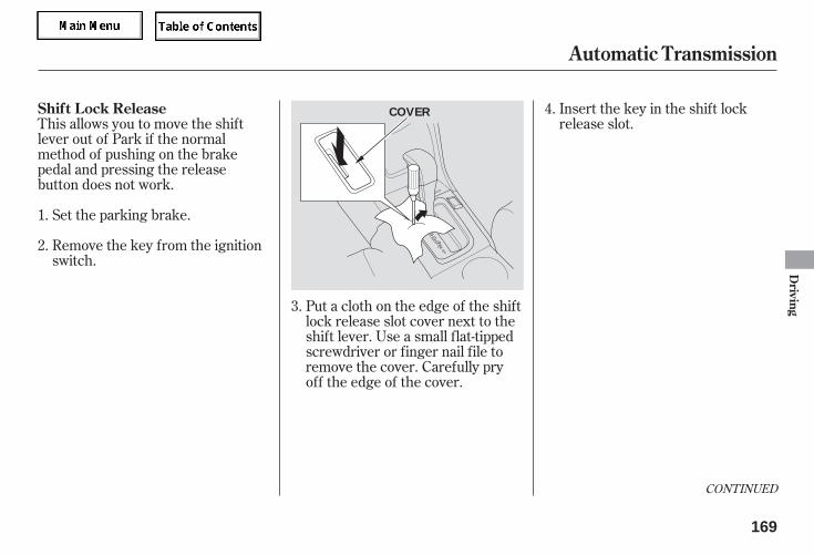
Put a cloth on the edge of the shiftlock release slot cover next to theshift lever. Use a small flat-tippedscrewdriver or finger nail file toremove the cover. Carefully pryoff the edge of the cover.
Insert the key in the shift lockrelease slot.This allows you to move the shift
lever out of Park if the normalmethod of pushing on the brakepedal and pressing the releasebutton does not work.
Remove the key from the ignitionswitch.
Set the parking brake.1.
2.
3.
4.
CONTINUED
Automatic Transmission
Shift Lock Release
Driving
169
COVER
05/09/02 11:56:16 31SDR610 0172
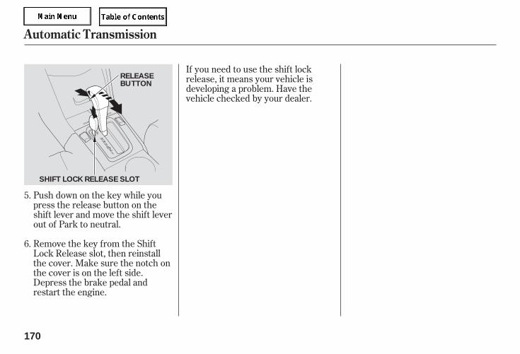
Push down on the key while youpress the release button on theshift lever and move the shift leverout of Park to neutral.
Remove the key from the ShiftLock Release slot, then reinstallthe cover. Make sure the notch onthe cover is on the left side.Depress the brake pedal andrestart the engine.
If you need to use the shift lockrelease, it means your vehicle isdeveloping a problem. Have thevehicle checked by your dealer.
5.
6.
Automatic Transmission
170
RELEASEBUTTON
SHIFT LOCK RELEASE SLOT
05/09/02 11:56:21 31SDR610 0173
-
-
The engine restarts when yourelease the brake pedal. Even whileyou are pressing down on the brakepedal, the engine restarts if theconditions below are met.
You move the shift lever from N toR, or from D3 to 2nd.You step on the accelerator pedal.
Your vehicle has an auto idle stopsystem. After your vehicle comes toa halt, the engine shuts offautomatically if all the followingconditions are met.
The vehicle speed is over 8 mph(12 km/h) before the vehiclecomes to a stop.The engine coolant is nearly up tonormal operating temperature.The shift lever is in D, D3 or N.You are pressing on the brakepedal.You are not pressing on theaccelerator pedal.The IMA battery is chargedenough to operate the system.Fan speed lower fan speeds, ineither AUTO or manual modes.
During Auto Idle Stop, the IMAcharge and power brake vacuumreserve is monitored by the system.If the vacuum reserve drops belowan optimal level, the engine willrestart to replenish the vacuumsupply. If the IMA charge dropsbelow an optimal level, the enginewill restart to recharge the IMAbattery.
The auto idle stop system may notwork if the temperature of the IMAbattery is extremely high orextremely low.
While the auto idle stop system isworking, the auto idle stop indicatorblinks (see page ).
Outside temperature is between10 100 degrees F.The vent mode is neither in
nor .
172
Automatic Transmission
Auto Idle Stop
Driving
171
05/09/02 11:56:33 31SDR610 0174
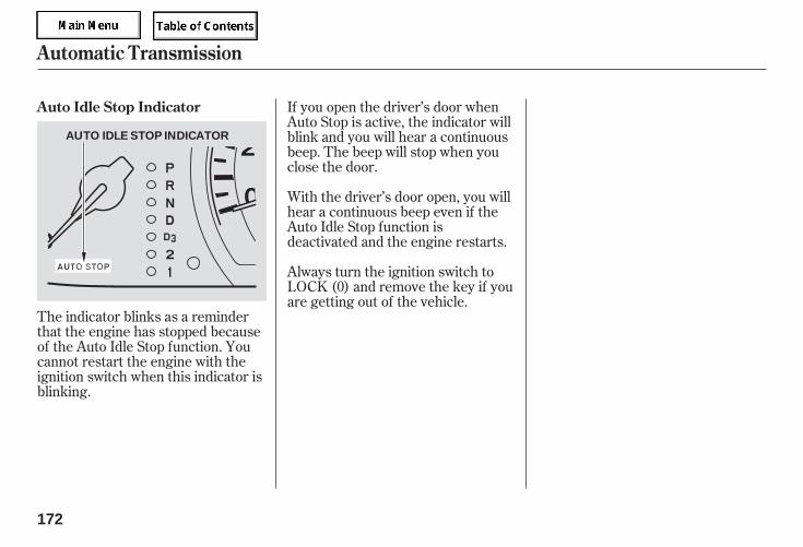
If you open the driver’s door whenAuto Stop is active, the indicator willblink and you will hear a continuousbeep. The beep will stop when youclose the door.
With the driver’s door open, you willhear a continuous beep even if theAuto Idle Stop function isdeactivated and the engine restarts.
Always turn the ignition switch toLOCK (0) and remove the key if youare getting out of the vehicle.
The indicator blinks as a reminderthat the engine has stopped becauseof the Auto Idle Stop function. Youcannot restart the engine with theignition switch when this indicator isblinking.
Automatic Transmission
Auto Idle Stop Indicator
172
AUTO IDLE STOP INDICATOR
05/09/02 11:56:38 31SDR610 0175
Always use the parking brake whenyou park your vehicle. Make surethe parking brake is set firmly, oryour vehicle may roll if it is parkedon an incline.
Set the parking brake before you putthe transmission in Park. This keepsthe vehicle from moving and puttingpressure on the parking mechanismin the transmission.
If the vehicle is facing uphill, turnthe front wheels away from thecurb.
If the vehicle is facing downhill,turn the front wheels toward thecurb.
Make sure the parking brake isfully released before driving away.Driving with the parking brakepartially set can overheat ordamage the rear brakes.
Make sure the moonroof and thewindows are closed.
Check the indicator on theinstrument panel to verify that thesecurity system is set.
Lock the doors with the key or theremote transmitter.
Place any packages, valuables, etc.,in the trunk or take them with you.
Turn off the lights.
Never park over dry leaves, tallgrass, or other flammablematerials. The hot three waycatalytic converter could causethese materials to catch on fire.
Parking Tips
Parking
Driving
173
05/09/02 11:56:47 31SDR610 0176
Check the brakes after drivingthrough deep water. Apply thebrakes moderately to see if they feelnormal. If not, apply them gently andfrequently until they do. Be extracautious in your driving.
The hydraulic system that operatesthe brakes has two separate circuits.Each circuit works diagonally acrossthe vehicle (the left-front brake isconnected with the right-rear brake,etc.). If one circuit should develop aproblem, you will still have brakingat two wheels.
Your vehicle is equipped with discbrakes. A power assist helps reducethe effort needed on the brake pedal.The ABS helps you retain steeringcontrol when braking very hard.
Put your foot on the brake pedal onlywhen you intend to brake. Restingyour foot on the pedal keeps thebrakes applied lightly, builds up heat,increases wear and reduces theireffectiveness. It also keeps yourbrake lights on all the time,confusing drivers behind you.
Constant application of the brakeswhen going down a long hill buildsup heat and reduces their effective-ness. Use the engine to assist thebrakes by taking your foot off theaccelerator and downshifting to alower gear.
If the brake pads need replacing, youwill hear a distinctive, metallicscreeching sound when you applythe brake pedal. If you do not havethe brake pads replaced, they willscreech all the time. It is normal forthe brakes to occasionally squeal orsqueak when you apply them.
Braking System
Brake Wear Indicators
Braking System Design
174
05/09/02 11:56:53 31SDR610 0177
The anti-lock brake system (ABS)helps prevent the brakes fromlocking up, and helps you retainsteering control by pumping thebrakes rapidly, much faster than aperson can do it.
The ABS also balances the front-to-rear braking distribution accordingto vehicle loading.
this defeats the purpose of the ABS.Let the ABS work for you by alwayskeeping firm, steady pressure on thebrake pedal as you steer away fromthe hazard. This is sometimesreferred to as ‘‘stomp and steer.’’
If this indicator comes on, the anti-lock function of the braking systemhas shut down. The brakes still worklike a conventional system, butwithout anti-lock. You should haveyour dealer inspect your vehicle assoon as possible.
If the ABS indicator and the brakesystem indicator come on together,and the parking brake is fullyreleased, the front-to-rear brakingdistribution system may also be shutdown.
You will feel a pulsation in the brakepedal when the ABS activates, andyou may hear some noise. This isnormal: it is the ABS rapidlypumping the brakes. On drypavement, you will need to press onthe brake pedal very hard before theABS activates. However, you mayfeel the ABS activate immediately ifyou are trying to stop on snow or ice.
You should never pump the brake pedal;
CONTINUED
Anti-lock Brakes (ABS)
Anti-lock Brakes (ABS) Activating the Anti-lock Brakes ABS Indicator
Driving
175
05/09/02 11:57:01 31SDR610 0178
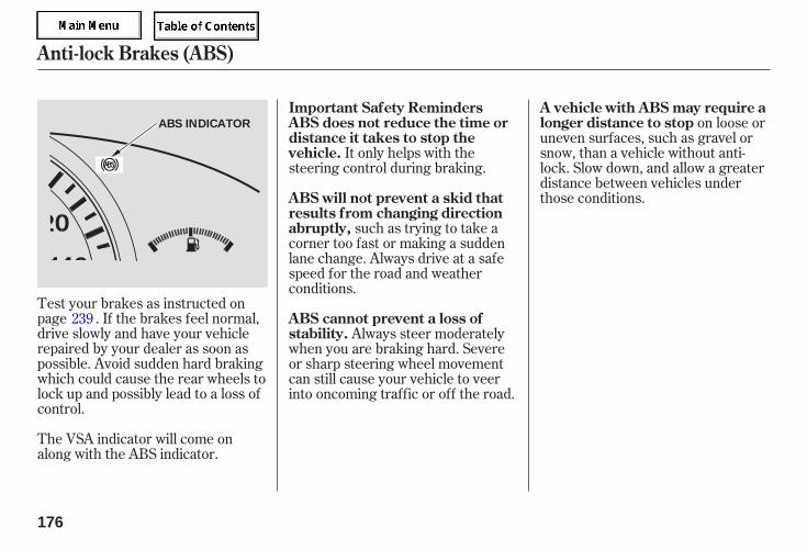
Test your brakes as instructed onpage . If the brakes feel normal,drive slowly and have your vehiclerepaired by your dealer as soon aspossible. Avoid sudden hard brakingwhich could cause the rear wheels tolock up and possibly lead to a loss ofcontrol.
The VSA indicator will come onalong with the ABS indicator.
on loose oruneven surfaces, such as gravel orsnow, than a vehicle without anti-lock. Slow down, and allow a greaterdistance between vehicles underthose conditions.
It only helps with thesteering control during braking.
such as trying to take acorner too fast or making a suddenlane change. Always drive at a safespeed for the road and weatherconditions.
Always steer moderatelywhen you are braking hard. Severeor sharp steering wheel movementcan still cause your vehicle to veerinto oncoming traffic or off the road.
239
Anti-lock Brakes (ABS)
A vehicle with ABS may require alonger distance to stop
Important Safety RemindersABS does not reduce the time ordistance it takes to stop thevehicle.
ABS will not prevent a skid thatresults from changing directionabruptly,
ABS cannot prevent a loss ofstability.
176
ABS INDICATOR
05/09/02 11:57:08 31SDR610 0179
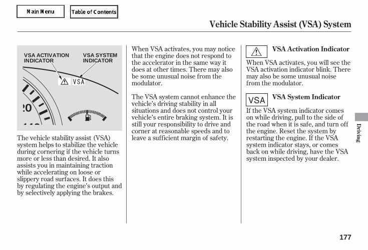
When VSA activates, you will see theVSA activation indicator blink. Theremay also be some unusual noisefrom the modulator.
When VSA activates, you may noticethat the engine does not respond tothe accelerator in the same way itdoes at other times. There may alsobe some unusual noise from themodulator.
The VSA system cannot enhance thevehicle’s driving stability in allsituations and does not control yourvehicle’s entire braking system. It isstill your responsibility to drive andcorner at reasonable speeds and toleave a sufficient margin of safety.
If the VSA system indicator comeson while driving, pull to the side ofthe road when it is safe, and turn offthe engine. Reset the system byrestarting the engine. If the VSAsystem indicator stays, or comesback on while driving, have the VSAsystem inspected by your dealer.
The vehicle stability assist (VSA)system helps to stabilize the vehicleduring cornering if the vehicle turnsmore or less than desired. It alsoassists you in maintaining tractionwhile accelerating on loose orslippery road surfaces. It does thisby regulating the engine’s output andby selectively applying the brakes.
VSA Activation Indicator
VSA System Indicator
Vehicle Stability Assist (VSA) System
Driving
177
VSA SYSTEMINDICATOR
VSA ACTIVATIONINDICATOR
05/09/02 11:57:17 31SDR610 0180
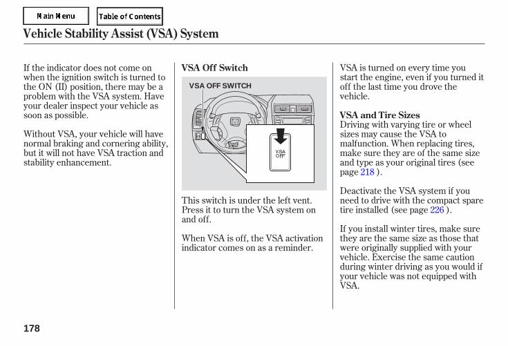
Without VSA, your vehicle will havenormal braking and cornering ability,but it will not have VSA traction andstability enhancement.
VSA is turned on every time youstart the engine, even if you turned itoff the last time you drove thevehicle.
Driving with varying tire or wheelsizes may cause the VSA tomalfunction. When replacing tires,make sure they are of the same sizeand type as your original tires (seepage ).
Deactivate the VSA system if youneed to drive with the compact sparetire installed (see page ).
If you install winter tires, make surethey are the same size as those thatwere originally supplied with yourvehicle. Exercise the same cautionduring winter driving as you would ifyour vehicle was not equipped withVSA.
When VSA is off, the VSA activationindicator comes on as a reminder.
If the indicator does not come onwhen the ignition switch is turned tothe ON (II) position, there may be aproblem with the VSA system. Haveyour dealer inspect your vehicle assoon as possible.
This switch is under the left vent.Press it to turn the VSA system onand off.
218
226
VSA Off Switch
VSA and Tire Sizes
Vehicle Stability Assist (VSA) System
178
VSA OFF SWITCH
05/09/02 11:57:25 31SDR610 0181
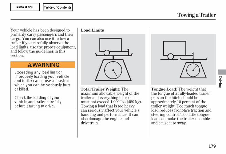
Your vehicle has been designed toprimarily carry passengers and theircargo. You can also use it to tow atrailer if you carefully observe theload limits, use the proper equipment,and follow the guidelines in thissection.
Themaximum allowable weight of thetrailer and everything in or on itmust not exceed 1,000 lbs (450 kg).Towing a load that is too heavycan seriously affect your vehicle’shandling and performance. It canalso damage the engine anddrivetrain.
The weight thatthe tongue of a fully-loaded trailerputs on the hitch should beapproximately 10 percent of thetrailer weight. Too much tongueload reduces front-tire traction andsteering control. Too little tongueload can make the trailer unstableand cause it to sway.
Load Limits
Total Trailer Weight: Tongue Load:
Towing a Trailer
Driving
179
Exceeding any load limit orimproperly loading your vehicleand trailer can cause a crash inwhich you can be seriously hurtor killed.
Check the loading of yourvehicle and trailer carefullybefore starting to drive.
05/09/02 11:57:31 31SDR610 0182
To achieve a proper tongue load,start by loading 60 % of the loadtoward the front of the trailer and 40% toward the rear, then re-adjust theload as needed.
The total weight of the vehicle, alloccupants, all cargo, and thetongue load must not exceed:
The total weight of each axle mustnot exceed:
The best way to confirm that vehicleand trailer weights are within limitsis to have them checked at a publicscale. To locate the public scales inyour area, consult your local yellowpages or ask your dealer forassistance.
Using a suitable scale or a specialtongue load gauge, check the tongueload the first time you set up atowing combination (a fully-loadedvehicle and trailer), then recheck thetongue load whenever the conditionschange.
on the front axle
on the rear axle
Checking Loads
Gross Vehicle Weight Rating(GVWR):
Gross Axle Weight Rating(GAWR):
Towing a Trailer
180
4,565 lbs (2,070 kg)
2,470 Ibs (1,120 kg)
2,140 Ibs (970 kg)
05/09/02 11:57:37 31SDR610 0183
Honda recommends that any trailerhaving a total weight of 1,000 lbs(450 kg) or more be equipped withits own electric or surge-type brakes.
If you choose electric brakes, besure they are electrically actuated.Do not attempt to tap into yourvehicle’s hydraulic system. Nomatter how successful it may seem,any attempt to attach trailer brakesto your vehicle’s hydraulic systemwill lower braking effectiveness andcreate a potential hazard.
See your trailer dealer for moreinformation on installing electricbrakes.
Any hitch used on your vehicle mustbe properly bolted to the underbody.
Always use safety chains when youtow a trailer. Make sure the chainsare secured to the trailer and hitch,and that they cross under the tongueand can catch the trailer if itbecomes unhitched. Leave enoughslack to allow the trailer to turncorners easily, but do not let thechains drag on the ground.
Towing can require a variety ofequipment, depending on the size ofyour trailer, how it will be used, howmuch load you are towing, andwhere you tow. To ensure the bestquality, we recommend that youpurchase Honda equipmentwhenever possible.
Discuss your needs with your trailersales or rental agency, and follow theguidelines in the rest of this section.Also make sure that all equipment isproperly installed and that it meetsfederal, state, province, and localregulations.
Towing Equipment andAccessories
Trailer BrakesHitches
Safety Chains
Towing a Trailer
Driving
181
05/09/02 11:57:46 31SDR610 0184
Ask your trailer sales or rentalagency if any other items arerecommended or required for yourtowing situation.
Since lighting and wiring vary bytrailer type and brand, you shouldhave a qualified technician install asuitable connector between thevehicle and the trailer. Improperequipment or installation can causedamage to your vehicle’s electricalsystem and affect your vehiclewarranty.
Trailer lights and equipment mustcomply with federal and stateregulations. Check with your trailersales or rental agency for therequirements in your area, and useonly equipment designed for yourvehicle.
Many states and provinces requirespecial outside mirrors when towinga trailer. Even if they don’t, youshould install special mirrors if youcannot clearly see behind you, or ifthe trailer creates a blind spot.
Trailer Lights Additional Towing Equipment
Towing a Trailer
182
05/09/02 11:57:51 31SDR610 0185
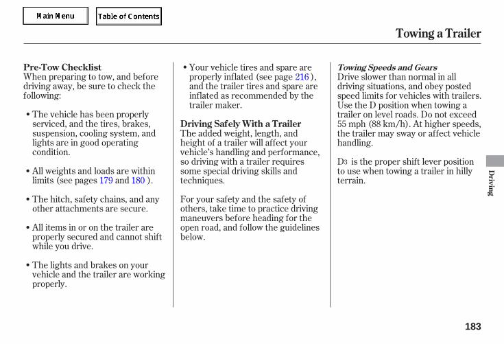
When preparing to tow, and beforedriving away, be sure to check thefollowing:
The vehicle has been properlyserviced, and the tires, brakes,suspension, cooling system, andlights are in good operatingcondition.
The lights and brakes on yourvehicle and the trailer are workingproperly.
All items in or on the trailer areproperly secured and cannot shiftwhile you drive.
The hitch, safety chains, and anyother attachments are secure.
All weights and loads are withinlimits (see pages and ).
Your vehicle tires and spare areproperly inflated (see page ),and the trailer tires and spare areinflated as recommended by thetrailer maker.
For your safety and the safety ofothers, take time to practice drivingmaneuvers before heading for theopen road, and follow the guidelinesbelow.
The added weight, length, andheight of a trailer will affect yourvehicle’s handling and performance,so driving with a trailer requiressome special driving skills andtechniques.
Drive slower than normal in alldriving situations, and obey postedspeed limits for vehicles with trailers.Use the D position when towing atrailer on level roads. Do not exceed55 mph (88 km/h). At higher speeds,the trailer may sway or affect vehiclehandling.
D is the proper shift lever positionto use when towing a trailer in hillyterrain.179 180
216
3
Pre-Tow Checklist
Driving Safely With a Trailer
Towing Speeds and Gears
Towing a Trailer
Driving
183
05/09/02 11:58:01 31SDR610 0186
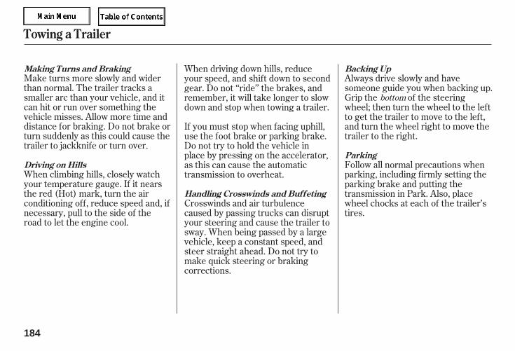
Make turns more slowly and widerthan normal. The trailer tracks asmaller arc than your vehicle, and itcan hit or run over something thevehicle misses. Allow more time anddistance for braking. Do not brake orturn suddenly as this could cause thetrailer to jackknife or turn over.
When climbing hills, closely watchyour temperature gauge. If it nearsthe red (Hot) mark, turn the airconditioning off, reduce speed and, ifnecessary, pull to the side of theroad to let the engine cool.
Always drive slowly and havesomeone guide you when backing up.Grip the of the steeringwheel; then turn the wheel to the leftto get the trailer to move to the left,and turn the wheel right to move thetrailer to the right.
Follow all normal precautions whenparking, including firmly setting theparking brake and putting thetransmission in Park. Also, placewheel chocks at each of the trailer’stires.
Crosswinds and air turbulencecaused by passing trucks can disruptyour steering and cause the trailer tosway. When being passed by a largevehicle, keep a constant speed, andsteer straight ahead. Do not try tomake quick steering or brakingcorrections.
When driving down hills, reduceyour speed, and shift down to secondgear. Do not ‘‘ride’’ the brakes, andremember, it will take longer to slowdown and stop when towing a trailer.
If you must stop when facing uphill,use the foot brake or parking brake.Do not try to hold the vehicle inplace by pressing on the accelerator,as this can cause the automatictransmission to overheat.
bottom
Making Turns and Braking
Driving on Hills
Handling Crosswinds and Buffeting
Backing Up
Parking
Towing a Trailer
184
05/09/02 11:58:10 31SDR610 0187
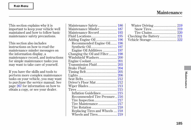
If you have the skills and tools toperform more complex maintenancetasks on your vehicle, you may wantto purchase the service manual. Seepage for information on how toobtain a copy, or see your dealer.
This section explains why it isimportant to keep your vehicle wellmaintained and how to follow basicmaintenance safety precautions.
This section also includesinstructions on how to read themaintenance minder messages onthe information display, amaintenance record, and instructionsfor simple maintenance tasks youmay want to take care of yourself.
......................Maintenance Safety . 186....................Maintenance Minder . 187....................Maintenance Record . 193
..............................Fluid Locations . 195........................Adding Engine Oil . 196
.......Recommended Engine Oil . 196..............................Synthetic Oil . 197
................Engine Oil Additives . 197.........Changing the Oil and Filter . 198
....................Windshield Washers . 200..............................Engine Coolant . 201
.......................Transmission Fluid . 203....................................Brake Fluid . 204....................................Timing Belt . 205
.............................................Lights . 206.......................................Seat Belts . 212
........................Driver’s Floor Mat . 212.................................Wiper Blades . 213
...............................................Tires . 215..................Inflation Guidelines . 215
.Recommended Tire Pressure . 216..........................Tire Inspection . 217
.....................Tire Maintenance . 217.............................Tire Rotation . 218
...Replacing Tires and Wheels . 218......................Wheels and Tires . 219
..........................Winter Driving . 219.............................Snow Tires . 219............................Tire Chains . 220
...................Checking the Battery . 221.............................Vehicle Storage . 222
267
Maintenance
Maintenance
185
05/09/02 11:58:15 31SDR610 0188
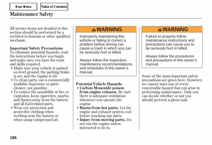
All service items not detailed in thissection should be performed by acertified technician or other qualifiedmechanic.
To eliminate potential hazards, readthe instructions before you begin,and make sure you have the toolsand skills required.
To clean parts, use a commerciallyavailable degreaser or partscleaner, not gasoline.To reduce the possibility of fire orexplosion, keep cigarettes, sparks,and flames away from the batteryand all fuel-related parts.Wear eye protection andprotective clothing whenworking near the battery orwhen using compressed air.
Be surethere is adequate ventilationwhenever you operate theengine.
Let theengine and exhaust system coolbefore touching any parts.
Donot run the engine unlessinstructed to do so.
Some of the most important safetyprecautions are given here. However,we cannot warn you of everyconceivable hazard that can arise inperforming maintenance. Only youcan decide whether or not youshould perform a given task.
Make sure your vehicle is parkedon level ground, the parking brakeis set, and the engine is off.
Maintenance Safety
Important Safety Precautions
Carbon Monoxide poisonfrom engine exhaust.
Burns from hot parts.
Injury from moving parts.
Potential Vehicle Hazards
186
Failure to properly followmaintenance instructions andprecautions can cause you tobe seriously hurt or killed.
Always follow the proceduresand precautions in this owner’smanual.
Improperly maintaining thisvehicle or failing to correct aproblem before driving cancause a crash in which you canbe seriously hurt or killed.
Always follow the inspection,maintenance recommendations,and schedules in this owner’smanual.
05/09/02 11:58:25 31SDR610 0189
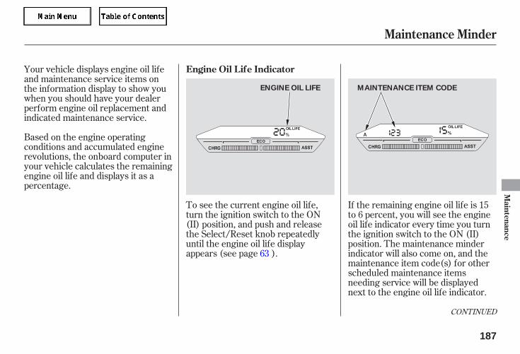
Your vehicle displays engine oil lifeand maintenance service items onthe information display to show youwhen you should have your dealerperform engine oil replacement andindicated maintenance service.
Based on the engine operatingconditions and accumulated enginerevolutions, the onboard computer inyour vehicle calculates the remainingengine oil life and displays it as apercentage.
To see the current engine oil life,turn the ignition switch to the ON(II) position, and push and releasethe Select/Reset knob repeatedlyuntil the engine oil life displayappears (see page ).
If the remaining engine oil life is 15to 6 percent, you will see the engineoil life indicator every time you turnthe ignition switch to the ON (II)position. The maintenance minderindicator will also come on, and themaintenance item code(s) for otherscheduled maintenance itemsneeding service will be displayednext to the engine oil life indicator.
63
CONTINUED
Maintenance Minder
Engine Oil Life Indicator
Maintenance
187
ENGINE OIL LIFE MAINTENANCE ITEM CODE
05/09/02 11:58:32 31SDR610 0190
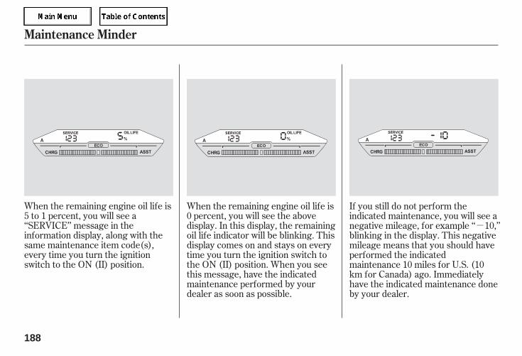
-
When the remaining engine oil life is5 to 1 percent, you will see a‘‘SERVICE’’ message in theinformation display, along with thesame maintenance item code(s),every time you turn the ignitionswitch to the ON (II) position.
When the remaining engine oil life is0 percent, you will see the abovedisplay. In this display, the remainingoil life indicator will be blinking. Thisdisplay comes on and stays on everytime you turn the ignition switch tothe ON (II) position. When you seethis message, have the indicatedmaintenance performed by yourdealer as soon as possible.
If you still do not perform theindicated maintenance, you will see anegative mileage, for example ‘‘ 10,’’blinking in the display. This negativemileage means that you should haveperformed the indicatedmaintenance 10 miles for U.S. (10km for Canada) ago. Immediatelyhave the indicated maintenance doneby your dealer.
Maintenance Minder
188
05/09/02 11:58:38 31SDR610 0191
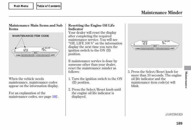
When the vehicle needsmaintenance, maintenance codesappear on the information display.
For an explanation of themaintenance codes, see page .
Turn the ignition switch to the ON(II) position.
If maintenance service is done bysomeone other than your dealer,reset the maintenance minder asfollows:
Press the Select/Reset knob untilthe engine oil life indicator isdisplayed.
Press the Select/Reset knob formore than 10 seconds. The engineoil life indicator and themaintenance item code(s) willblink.
Your dealer will reset the displayafter completing the requiredmaintenance service. You will see‘‘OIL LIFE 100 %’’ on the informationdisplay the next time you turn theignition switch to the ON (II)position.
3.
1.
2.
192
CONTINUED
Resetting the Engine Oil LifeIndicator
Maintenance Main Items and SubItems
Maintenance Minder
Maintenance
189
MAINTENANCE ITEM CODE
05/09/02 11:58:48 31SDR610 0192
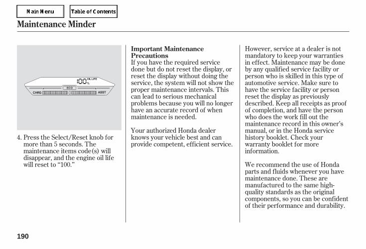
If you have the required servicedone but do not reset the display, orreset the display without doing theservice, the system will not show theproper maintenance intervals. Thiscan lead to serious mechanicalproblems because you will no longerhave an accurate record of whenmaintenance is needed.
Your authorized Honda dealerknows your vehicle best and canprovide competent, efficient service.
Press the Select/Reset knob formore than 5 seconds. Themaintenance items code(s) willdisappear, and the engine oil lifewill reset to ‘‘100.’’
However, service at a dealer is notmandatory to keep your warrantiesin effect. Maintenance may be doneby any qualified service facility orperson who is skilled in this type ofautomotive service. Make sure tohave the service facility or personreset the display as previouslydescribed. Keep all receipts as proofof completion, and have the personwho does the work fill out themaintenance record in this owner’smanual, or in the Honda servicehistory booklet. Check yourwarranty booklet for moreinformation.
We recommend the use of Hondaparts and fluids whenever you havemaintenance done. These aremanufactured to the same high-quality standards as the originalcomponents, so you can be confidentof their performance and durability.
4.
Important MaintenancePrecautions
Maintenance Minder
190
05/09/02 11:58:54 31SDR610 0193
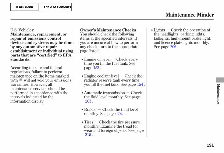
-
-
-
-
-
-
#
U.S. Vehicles:You should check the followingitems at the specified intervals. Ifyou are unsure of how to performany check, turn to the appropriatepage listed.
Lights Check the operation ofthe headlights, parking lights,taillights, high-mount brake light,and license plate lights monthly.See page .
Engine coolant level Check theradiator reserve tank every timeyou fill the fuel tank. See page .
Engine oil level Check everytime you fill the fuel tank. Seepage .
Automatic transmission Checkthe fluid level monthly. See page
.
Brakes Check the fluid levelmonthly. See page .
Tires Check the tire pressuremonthly. Examine the tread forwear and foreign objects. See page
.
According to state and federalregulations, failure to performmaintenance on the items markedwith will not void your emissionswarranties. However, allmaintenance services should beperformed in accordance with theintervals indicated by theinformation display.
153
154
203
204
215
206
Maintenance, replacement, orrepair of emissions controldevices and systems may be doneby any automotive repairestablishment or individual usingparts that are ‘‘certif ied’’ to EPAstandards.
Owner’s Maintenance Checks
Maintenance Minder
Maintenance
191
05/09/02 11:59:03 31SDR610 0194
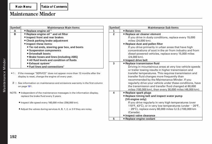
*
*
#
#
--
#
*
Maintenance Minder
192
Maintenance Main Items
Replace engine oil
Replace engine oil and oil filter
Inspect front and rear brakes
Check parking brake adjustment
Inspect these items:
Tie rod ends, steering gear box, and boots
Suspension components
Driveshaft boots
Brake hoses and lines (including ABS)
All fluid levels and condition of fluids
Exhaust system
Fuel lines and connections
Maintenance Sub Items
Rotate tires
Replace air cleaner element
Replace dust and pollen filter
Inspect drive belt
Replace transmission fluid
Replace spark plugs
Replace timing belt and inspect water pump
(V6 engine only)
Inspect valve clearance
Replace engine coolant
:
A
B
Symbol
1
2
3
4
5
Symbol1
1
See information on maintenance and emissions warranty in the first columnon page .
Inspect idle speed every 160,000 miles (256,000 km).
Adjust the valves during services A, B, 1, 2, or 3 if they are noisy.
If the message ‘‘SERVICE’’ does not appear more than 12 months after thedisplay is reset, change the engine oil every year.
Independent of the maintenance messages in the information display,replace the brake fluid every 3 years.
NOTE:
1 :
191
If you drive in dusty conditions, replace every 15,000miles (24,000 km).
If you drive primarily in urban areas that have highconcentrations of soot in the air from industry and fromdiesel-powered vehicles, replace every 15,000 miles(24,000 km).
Driving in mountainous areas at very low vehicle speedsor trailer towing results in higher transmission andtransfer temperatures. This requires transmission andtransfer fluid changes more frequently thanrecommended by the Maintenance Minder. If youregularly drive your vehicle under these conditions, havethe transmission and transfer fluid changed at 60,000miles (100,000 km), then every 30,000 miles (48,000 km).
If you drive regularly in very high temperatures (over110°F, 43°C), or in very low temperatures (under 20°F,
29°C), replace every 60,000 miles (U.S.)/100,000 km(Canada).
Main
tenance
Min
der
05/09/02 11:59:11 31SDR610 0195
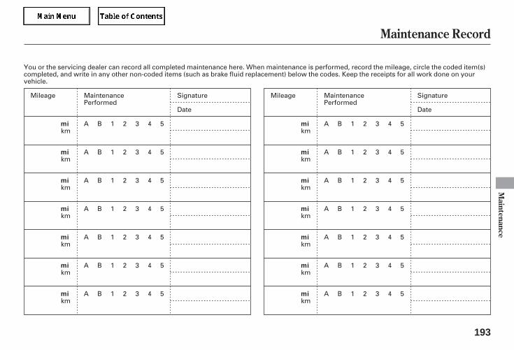
Maintenance Record
Maintenance
193
mi
mi
mi
mi
mi
mi
mi
mi
mi
mi
mi
mi
mi
mi
You or the servicing dealer can record all completed maintenance here. When maintenance is performed, record the mileage, circle the coded item(s)completed, and write in any other non-coded items (such as brake fluid replacement) below the codes. Keep the receipts for all work done on yourvehicle.
MaintenancePerformed
A B 1 2 3 4 5
A B 1 2 3 4 5
A B 1 2 3 4 5
A B 1 2 3 4 5
A B 1 2 3 4 5
A B 1 2 3 4 5
A B 1 2 3 4 5
Signature
Date
MaintenancePerformed
A B 1 2 3 4 5
A B 1 2 3 4 5
A B 1 2 3 4 5
A B 1 2 3 4 5
A B 1 2 3 4 5
A B 1 2 3 4 5
A B 1 2 3 4 5
Signature
Date
Mileage
km
km
km
km
km
km
km
Mileage
km
km
km
km
km
km
km
05/09/02 11:59:17 31SDR610 0196
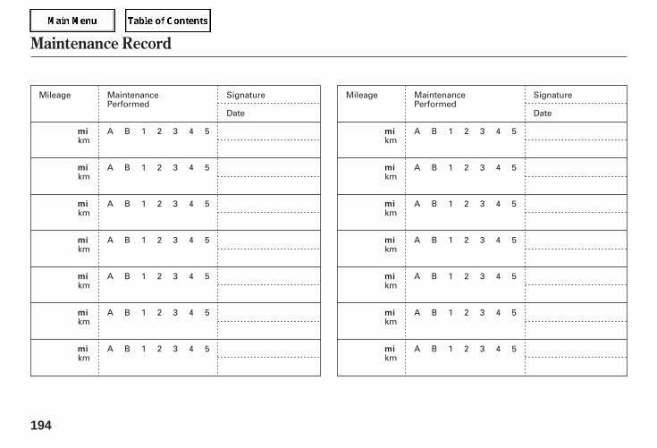
Maintenance Record
194
mi
mi
mi
mi
mi
mi
mi
mi
mi
mi
mi
mi
mi
mi
MaintenancePerformed
A B 1 2 3 4 5
A B 1 2 3 4 5
A B 1 2 3 4 5
A B 1 2 3 4 5
A B 1 2 3 4 5
A B 1 2 3 4 5
A B 1 2 3 4 5
Signature
Date
MaintenancePerformed
A B 1 2 3 4 5
A B 1 2 3 4 5
A B 1 2 3 4 5
A B 1 2 3 4 5
A B 1 2 3 4 5
A B 1 2 3 4 5
A B 1 2 3 4 5
Signature
Date
Mileage
km
km
km
km
km
km
km
Mileage
km
km
km
km
km
km
km
05/09/02 11:59:22 31SDR610 0197
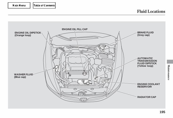
Fluid Locations
Maintenance
195
ENGINE OIL FILL CAP
RADIATOR CAP
ENGINE OIL DIPSTICK(Orange loop)
WASHER FLUID(Blue cap)
BRAKE FLUID(Gray cap)
AUTOMATICTRANSMISSIONFLUID DIPSTICK(Yellow loop)
ENGINE COOLANTRESERVOIR
05/09/02 11:59:26 31SDR610 0198
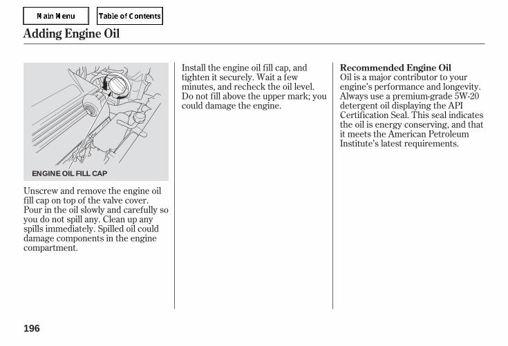
Oil is a major contributor to yourengine’s performance and longevity.Always use a premium-grade 5W-20detergent oil displaying the APICertification Seal. This seal indicatesthe oil is energy conserving, and thatit meets the American PetroleumInstitute’s latest requirements.
Install the engine oil fill cap, andtighten it securely. Wait a fewminutes, and recheck the oil level.Do not fill above the upper mark; youcould damage the engine.
Unscrew and remove the engine oilfill cap on top of the valve cover.Pour in the oil slowly and carefully soyou do not spill any. Clean up anyspills immediately. Spilled oil coulddamage components in the enginecompartment.
Recommended Engine Oil
Adding Engine Oil
196
ENGINE OIL FILL CAP
05/09/02 11:59:32 31SDR610 0199
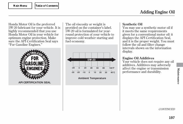
Honda Motor Oil is the preferred5W-20 lubricant for your vehicle. It ishighly recommended that you useHonda Motor Oil in your vehicle foroptimum engine protection. Makesure the API Certification Seal says‘‘For Gasoline Engines.’’
Your vehicle does not require any oiladditives. Additives may adverselyaffect the engine or transmissionperformance and durability.
The oil viscosity or weight isprovided on the container’s label.5W-20 oil is formulated for year-round protection of your vehicle toimprove cold weather starting andfuel economy.
You may use a synthetic motor oil ifit meets the same requirementsgiven for a conventional motor oil: itdisplays the API Certification Seal,and it is the proper weight. You mustfollow the oil and filter changeintervals shown on the informationdisplay.
CONTINUED
Synthetic Oil
Engine Oil Additives
Adding Engine Oil
Maintenance
197
API CERTIFICATION SEAL
Ambient Temperature
05/09/02 11:59:40 31SDR610 0200
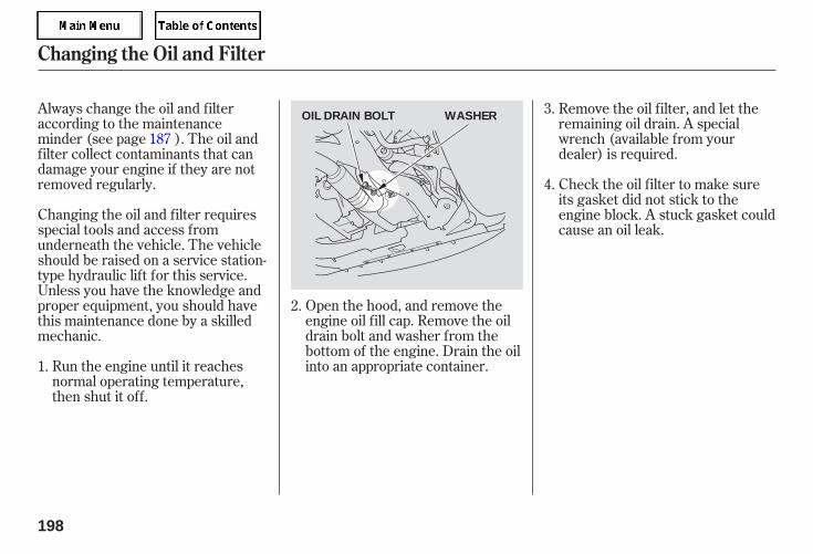
Open the hood, and remove theengine oil fill cap. Remove the oildrain bolt and washer from thebottom of the engine. Drain the oilinto an appropriate container.Run the engine until it reaches
normal operating temperature,then shut it off.
Changing the oil and filter requiresspecial tools and access fromunderneath the vehicle. The vehicleshould be raised on a service station-type hydraulic lift for this service.Unless you have the knowledge andproper equipment, you should havethis maintenance done by a skilledmechanic.
Always change the oil and filteraccording to the maintenanceminder (see page ). The oil andfilter collect contaminants that candamage your engine if they are notremoved regularly.
Remove the oil filter, and let theremaining oil drain. A specialwrench (available from yourdealer) is required.
Check the oil filter to make sureits gasket did not stick to theengine block. A stuck gasket couldcause an oil leak.
3.
2.
1.
4.
187
Changing the Oil and Filter
198
WASHEROIL DRAIN BOLT
05/09/02 11:59:46 31SDR610 0201
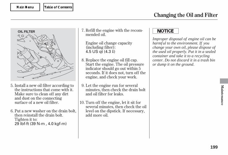
Install a new oil filter according tothe instructions that come with it.
Put a new washer on the drain bolt,then reinstall the drain bolt.Tighten it to:
Make sure to clean off any dirtand dust on the connectingsurface of a new oil filter.
Refill the engine with the recom-mended oil.
Engine oil change capacity(including filter):
Replace the engine oil fill cap.Start the engine. The oil pressureindicator should go out within 5seconds. If it does not, turn off theengine, and check your work.
Let the engine run for severalminutes, then check the drain boltand oil filter for leaks.
Turn off the engine, let it sit forseveral minutes, then check the oillevel on the dipstick. If necessary,add more oil.
5.
6.
7.
8.
9.
10.
Changing the Oil and Filter
Maintenance
199
OIL FILTER
29 lbf·ft (39 N·m , 4.0 kgf·m)
4.5 US qt (4.3 )
Improper disposal of engine oil can beharmf ul to the environment. If youchange your own oil, please dispose ofthe used oil properly. Put it in a sealedcontainer and take it to a recyclingcenter. Do not discard it in a trash binor dump it on the ground.
05/09/02 11:59:55 31SDR610 0202
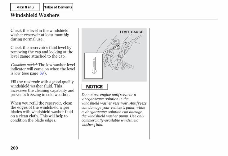
Check the level in the windshieldwasher reservoir at least monthlyduring normal use.
When you refill the reservoir, cleanthe edges of the windshield wiperblades with windshield washer fluidon a clean cloth. This will help tocondition the blade edges.
Fill the reservoir with a good-qualitywindshield washer fluid. Thisincreases the cleaning capability andprevents freezing in cold weather.
Check the reservoir’s fluid level byremoving the cap and looking at thelevel gauge attached to the cap.
The low washer levelindicator will come on when the levelis low (see page ).59
Canadian model:
Windshield Washers
200
LEVEL GAUGE
Do not use engine antif reeze or avinegar/water solution in thewindshield washer reservoir. Antif reezecan damage your vehicle’s paint, whilea vinegar/water solution can damagethe windshield washer pump. Use onlycommercially-available windshieldwasher f luid.
05/09/02 12:00:02 31SDR610 0203
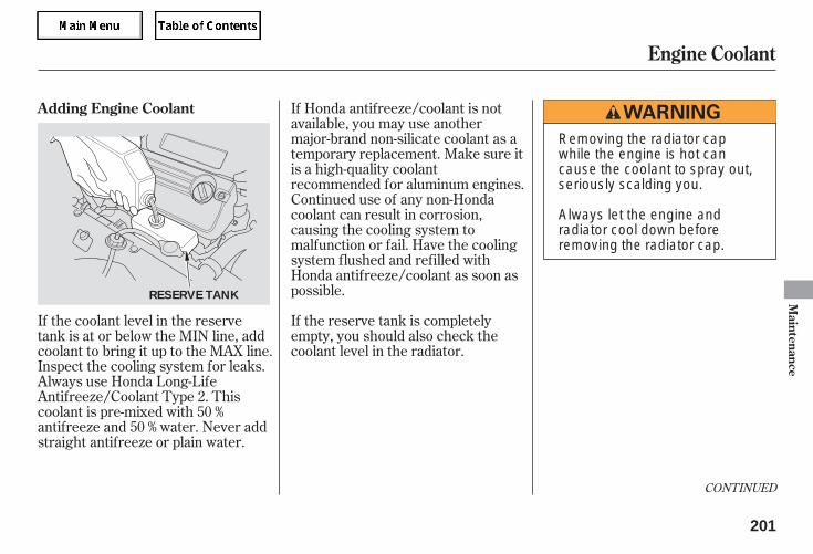
If Honda antifreeze/coolant is notavailable, you may use anothermajor-brand non-silicate coolant as atemporary replacement. Make sure itis a high-quality coolantrecommended for aluminum engines.Continued use of any non-Hondacoolant can result in corrosion,causing the cooling system tomalfunction or fail. Have the coolingsystem flushed and refilled withHonda antifreeze/coolant as soon aspossible.
If the reserve tank is completelyempty, you should also check thecoolant level in the radiator.
If the coolant level in the reservetank is at or below the MIN line, addcoolant to bring it up to the MAX line.Inspect the cooling system for leaks.Always use Honda Long-LifeAntifreeze/Coolant Type 2. Thiscoolant is pre-mixed with 50 %antifreeze and 50 % water. Never addstraight antifreeze or plain water.
CONTINUED
Adding Engine Coolant
Engine Coolant
Maintenance
201
RESERVE TANK
Removing the radiator capwhile the engine is hot cancause the coolant to spray out,seriously scalding you.
Always let the engine andradiator cool down beforeremoving the radiator cap.
05/09/02 12:00:08 31SDR610 0204
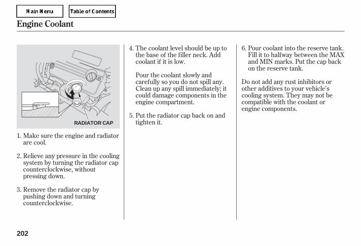
Pour coolant into the reserve tank.Fill it to halfway between the MAXand MIN marks. Put the cap backon the reserve tank.
Do not add any rust inhibitors orother additives to your vehicle’scooling system. They may not becompatible with the coolant orengine components.
The coolant level should be up tothe base of the filler neck. Addcoolant if it is low.
Pour the coolant slowly andcarefully so you do not spill any.Clean up any spill immediately; itcould damage components in theengine compartment.
Put the radiator cap back on andtighten it.
Make sure the engine and radiatorare cool.
Relieve any pressure in the coolingsystem by turning the radiator capcounterclockwise, withoutpressing down.
Remove the radiator cap bypushing down and turningcounterclockwise.
4.
1.
2.
3.
5.
6.
Engine Coolant
202
RADIATOR CAP
05/09/02 12:00:16 31SDR610 0205
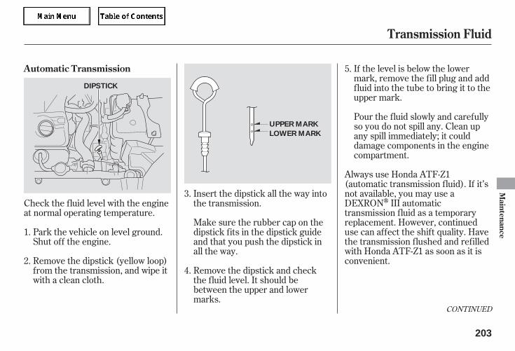
If the level is below the lowermark, remove the fill plug and addfluid into the tube to bring it to theupper mark.
Pour the fluid slowly and carefullyso you do not spill any. Clean upany spill immediately; it coulddamage components in the enginecompartment.
Always use Honda ATF-Z1(automatic transmission fluid). If it’snot available, you may use aDEXRON III automatictransmission fluid as a temporaryreplacement. However, continueduse can affect the shift quality. Havethe transmission flushed and refilledwith Honda ATF-Z1 as soon as it isconvenient.
Check the fluid level with the engineat normal operating temperature.
Park the vehicle on level ground.Shut off the engine.
Remove the dipstick (yellow loop)from the transmission, and wipe itwith a clean cloth.
Insert the dipstick all the way intothe transmission.
Make sure the rubber cap on thedipstick fits in the dipstick guideand that you push the dipstick inall the way.
Remove the dipstick and checkthe fluid level. It should bebetween the upper and lowermarks.
5.
3.
4.
1.
2.
CONTINUED
Automatic Transmission
Transmission Fluid
Maintenance
203
UPPER MARK
LOWER MARK
DIPSTICK
05/09/02 12:00:26 31SDR610 0206
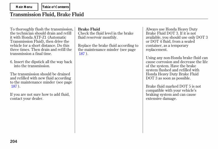
To thoroughly flush the transmission,the technician should drain and refillit with Honda ATF-Z1 (AutomaticTransmission Fluid), then drive thevehicle for a short distance. Do thisthree times. Then drain and refill thetransmission a final time.
Insert the dipstick all the way backinto the transmission.
If you are not sure how to add fluid,contact your dealer.
The transmission should be drainedand refilled with new fluid accordingto the maintenance minder (see page
).
Check the fluid level in the brakefluid reservoir monthly.
Replace the brake fluid according tothe maintenance minder (see page
).
Always use Honda Heavy DutyBrake Fluid DOT 3. If it is notavailable, you should use only DOT 3or DOT 4 fluid, from a sealedcontainer, as a temporaryreplacement.
Using any non-Honda brake fluid cancause corrosion and decrease the lifeof the system. Have the brakesystem flushed and refilled withHonda Heavy Duty Brake FluidDOT 3 as soon as possible.
Brake fluid marked DOT 5 is notcompatible with your vehicle’sbraking system and can causeextensive damage.
6.
187
187
Brake Fluid
Transmission Fluid, Brake Fluid
204
05/09/02 12:00:34 31SDR610 0207
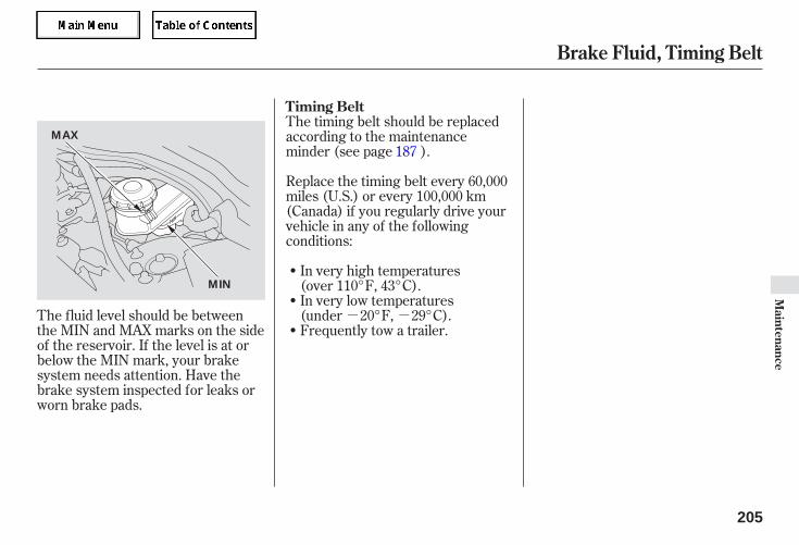
- -The fluid level should be betweenthe MIN and MAX marks on the sideof the reservoir. If the level is at orbelow the MIN mark, your brakesystem needs attention. Have thebrake system inspected for leaks orworn brake pads.
The timing belt should be replacedaccording to the maintenanceminder (see page ).
Replace the timing belt every 60,000miles (U.S.) or every 100,000 km(Canada) if you regularly drive yourvehicle in any of the followingconditions:
In very high temperatures(over 110°F, 43°C).In very low temperatures(under 20°F, 29°C).Frequently tow a trailer.
187
Brake Fluid, Timing Belt
Timing Belt
Maintenance
205
MAX
MIN
05/09/02 12:00:41 31SDR610 0208
The headlights were properly aimedwhen your vehicle was new. If youregularly carry heavy items in thetrunk or pull a trailer, readjustmentmay be required. Adjustmentsshould be performed by your dealeror other qualified mechanic.
Your vehicle has two bulbs on eachside, four in total. Make sure you arereplacing the bulb that is burned out.Your vehicle uses halogen headlightbulbs. When replacing a bulb, handleit by its plastic case and protect theglass from contact with your skin orhard objects. If you touch the glass,clean it with denatured alcohol and aclean cloth.
Headlight Aiming Replacing a Headlight Bulb
Lights
206
Halogen headlight bulbs get very hotwhen lit. Oil, perspiration, or a scratchon the glass can cause the bulb tooverheat and shatter.
05/09/02 12:00:46 31SDR610 0209
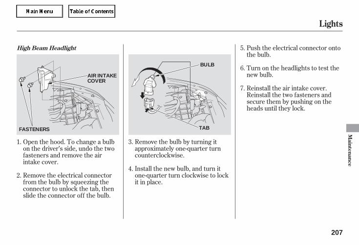
Remove the electrical connectorfrom the bulb by squeezing theconnector to unlock the tab, thenslide the connector off the bulb.
Remove the bulb by turning itapproximately one-quarter turncounterclockwise.
Install the new bulb, and turn itone-quarter turn clockwise to lockit in place.
Push the electrical connector ontothe bulb.
Turn on the headlights to test thenew bulb.
Open the hood. To change a bulbon the driver’s side, undo the twofasteners and remove the airintake cover.
Reinstall the air intake cover.Reinstall the two fasteners andsecure them by pushing on theheads until they lock.
1. 3.
2.4.
5.
6.
7.
High Beam Headlight
Lights
Maintenance
207
AIR INTAKECOVER
FASTENERS TAB
BULB
05/09/02 12:00:55 31SDR610 0210
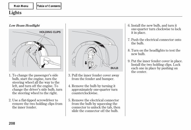
To change the passenger’s sidebulb, start the engine, turn thesteering wheel all the way to theleft, and turn off the engine. Tochange the driver’s side bulb, turnthe steering wheel to the right.
Use a flat-tipped screwdriver toremove the two holding clips fromthe inner fender.
Pull the inner fender cover awayfrom the fender and bumper.
Remove the bulb by turning itapproximately one-quarter turncounterclockwise.
Remove the electrical connectorfrom the bulb by squeezing theconnector to unlock the tab, thenslide the connector off the bulb.
Install the new bulb, and turn itone-quarter turn clockwise to lockit in place.
Push the electrical connector ontothe bulb.
Turn on the headlights to test thenew bulb.
Put the inner fender cover in place.Install the two holding clips. Lockeach one in place by pushing onthe center.
3.
4.
5.
1.
2.
6.
7.
8.
9.
Low Beam Headlight
Lights
208
HOLDING CLIPS
BULB
05/09/02 12:01:05 31SDR610 0211
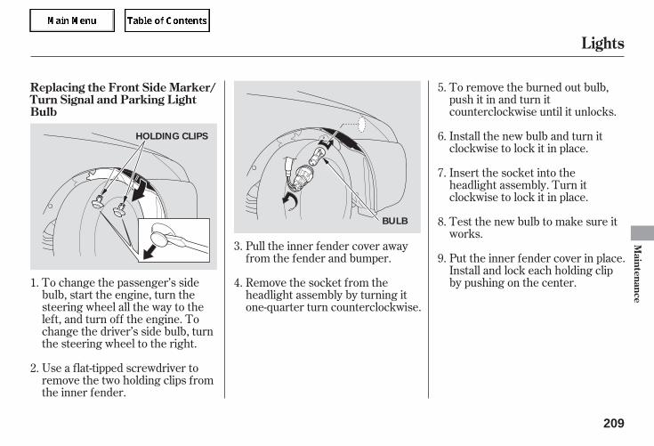
To change the passenger’s sidebulb, start the engine, turn thesteering wheel all the way to theleft, and turn off the engine. Tochange the driver’s side bulb, turnthe steering wheel to the right.
Use a flat-tipped screwdriver toremove the two holding clips fromthe inner fender.
To remove the burned out bulb,push it in and turn itcounterclockwise until it unlocks.
Install the new bulb and turn itclockwise to lock it in place.
Insert the socket into theheadlight assembly. Turn itclockwise to lock it in place.
Test the new bulb to make sure itworks.
Put the inner fender cover in place.Install and lock each holding clipby pushing on the center.
Pull the inner fender cover awayfrom the fender and bumper.
Remove the socket from theheadlight assembly by turning itone-quarter turn counterclockwise.
1.
3.
2.
4.
8.
7.
6.
9.
5.Replacing the Front Side Marker/Turn Signal and Parking LightBulb
Lights
Maintenance
209
HOLDING CLIPS
BULB
05/09/02 12:01:14 31SDR610 0212
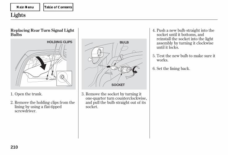
Open the trunk.
Remove the holding clips from thelining by using a flat-tippedscrewdriver.
Remove the socket by turning itone-quarter turn counterclockwise,and pull the bulb straight out of itssocket.
Push a new bulb straight into thesocket until it bottoms, andreinstall the socket into the lightassembly by turning it clockwiseuntil it locks.
Test the new bulb to make sure itworks.
Set the lining back.
2.
1.
4.
3.
5.
6.
Replacing Rear Turn Signal LightBulbs
Lights
210
HOLDING CLIPS BULB
SOCKET
05/09/02 12:01:23 31SDR610 0213
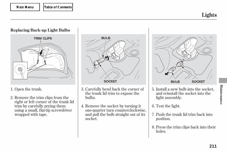
Open the trunk. Carefully bend back the corner ofthe trunk lid trim to expose thebulbs.
Remove the socket by turning itone-quarter turn counterclockwise,and pull the bulb straight out of itssocket.
Install a new bulb into the socket,and reinstall the socket into thelight assembly.
Test the light.
Push the trunk lid trim back intoposition.
Press the trim clips back into theirholes.
Remove the trim clips from theright or left corner of the trunk lidtrim by carefully prying themusing a small, flat-tip screwdriverwrapped with tape.
1. 3.
2.
4.
5.
6.
7.
8.
Replacing Back-up Light Bulbs
Lights
Maintenance
211
TRIM CLIPS BULB
SOCKET SOCKETBULB
05/09/02 12:01:32 31SDR610 0214
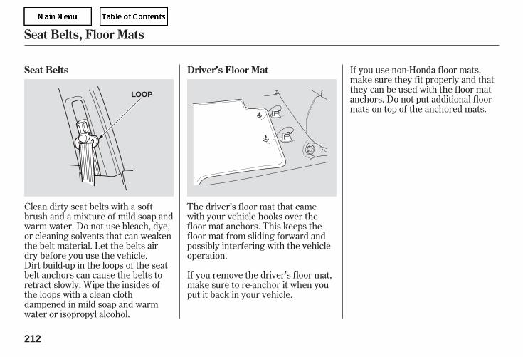
Dirt build-up in the loops of the seatbelt anchors can cause the belts toretract slowly. Wipe the insides ofthe loops with a clean clothdampened in mild soap and warmwater or isopropyl alcohol.
Clean dirty seat belts with a softbrush and a mixture of mild soap andwarm water. Do not use bleach, dye,or cleaning solvents that can weakenthe belt material. Let the belts airdry before you use the vehicle.
If you remove the driver’s floor mat,make sure to re-anchor it when youput it back in your vehicle.
If you use non-Honda floor mats,make sure they fit properly and thatthey can be used with the floor matanchors. Do not put additional floormats on top of the anchored mats.
The driver’s floor mat that camewith your vehicle hooks over thefloor mat anchors. This keeps thefloor mat from sliding forward andpossibly interfering with the vehicleoperation.
Seat Belts Driver’s Floor Mat
Seat Belts, Floor Mats
212
LOOP
05/09/02 12:01:39 31SDR610 0215
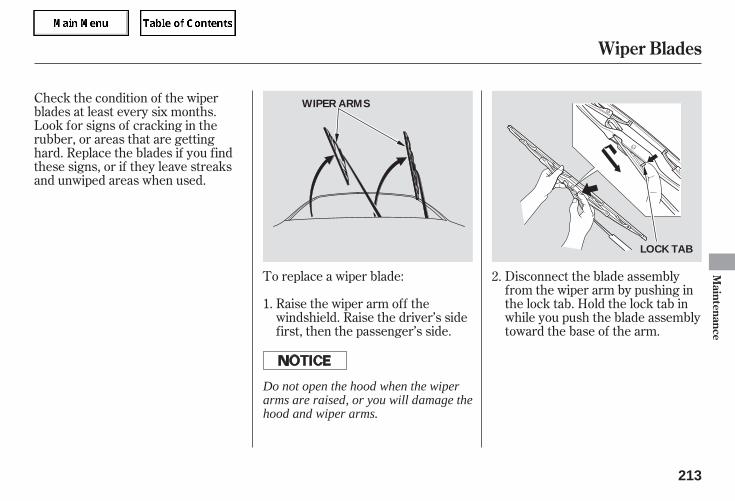
Check the condition of the wiperblades at least every six months.Look for signs of cracking in therubber, or areas that are gettinghard. Replace the blades if you findthese signs, or if they leave streaksand unwiped areas when used.
To replace a wiper blade:
Raise the wiper arm off thewindshield. Raise the driver’s sidefirst, then the passenger’s side.
Disconnect the blade assemblyfrom the wiper arm by pushing inthe lock tab. Hold the lock tab inwhile you push the blade assemblytoward the base of the arm.
2.
1.
Wiper Blades
Maintenance
213
WIPER ARMS
LOCK TAB
Do not open the hood when the wiperarms are raised, or you will damage thehood and wiper arms.
05/09/02 12:01:46 31SDR610 0216
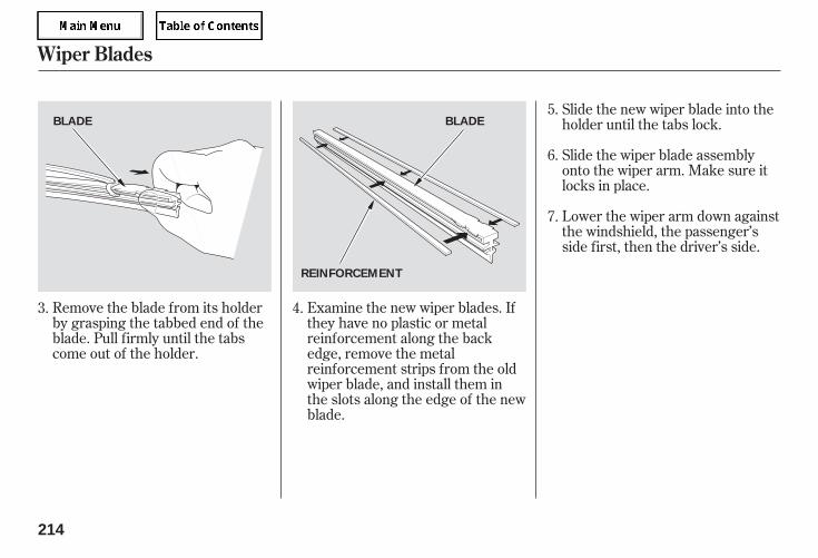
Remove the blade from its holderby grasping the tabbed end of theblade. Pull firmly until the tabscome out of the holder.
Examine the new wiper blades. Ifthey have no plastic or metalreinforcement along the backedge, remove the metalreinforcement strips from the oldwiper blade, and install them inthe slots along the edge of the newblade.
Slide the new wiper blade into theholder until the tabs lock.
Slide the wiper blade assemblyonto the wiper arm. Make sure itlocks in place.
Lower the wiper arm down againstthe windshield, the passenger’sside first, then the driver’s side.
3. 4.
5.
6.
7.
Wiper Blades
214
BLADE BLADE
REINFORCEMENT
05/09/02 12:01:53 31SDR610 0217
Keeping the tires properly inflatedprovides the best combination ofhandling, tread life, and ridingcomfort.
Underinflated tires wear unevenly,adversely affect handling and fueleconomy, and are more likely tofail from being overheated.
Overinflated tires can make yourvehicle ride more harshly, aremore prone to damage from roadhazards, and wear unevenly.
We recommend that you visuallycheck your tires every day. If youthink a tire might be low, check itimmediately with a tire gauge.
To safely operate your vehicle, yourtires must be the proper type andsize, in good condition with adequatetread, and correctly inflated.
The following pages give moredetailed information on how to takecare of your tires and what to dowhen they need to be replaced. Check the air pressures when the
tires are cold. This means thevehicle has been parked for at least 3hours, or driven less than 1 mile (1.6km). Add or release air, if needed, tomatch the recommended cold tirepressures on the next page.
Use a gauge to measure the airpressure in each tire at least once amonth. Even tires that are in goodcondition may lose 1 to 2 psi (10 to20 kPa, 0.1 to 0.2 kgf/cm ) permonth. Remember to check thespare tire at the same time.
Inflation Guidelines
Tires
Maintenance
215
Using tires that are excessivelyworn or improperly inflated cancause a crash in which you canbe seriously hurt or killed.
Follow all instructions in thisowner’s manual regarding tireinflation and maintenance.
05/09/02 12:02:00 31SDR610 0218
If you check air pressures when thetires are hot (driven for severalmiles), you will see readings 4 to 6psi (30 to 40 kPa, 0.3 to 0.4 kgf/cm )higher than the cold readings. Thisis normal. Do not let air out to matchthe recommended cold air pressure.The tire will be underinflated.
While tubeless tires have someability to self-seal if they arepunctured, you should look closelyfor punctures if a tire starts losingpressure.
Keep the inflation pressure of yournormal tires at 32 psi (220 kPa,2.2 kgf/cm ).
You should get your own tirepressure gauge and use it wheneveryou check your tire pressures. Thiswill make it easier for you to tell if apressure loss is due to a tire problemand not due to a variation betweengauges.
Keep the inflation pressure of yourcompact spare tire at 60 psi (420 kPa,4.2 kgf/cm ).
See page or refer to the tireplacard on the driver’s doorjamb forcorrect tire pressure.
253
Recommended Tire Pressure
Tires
216
05/09/02 12:02:06 31SDR610 0219
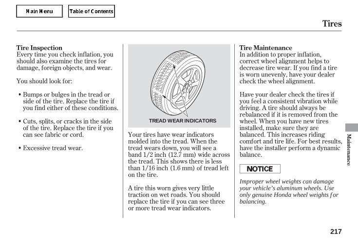
Every time you check inflation, youshould also examine the tires fordamage, foreign objects, and wear.
You should look for:
Have your dealer check the tires ifyou feel a consistent vibration whiledriving. A tire should always berebalanced if it is removed from thewheel. When you have new tiresinstalled, make sure they arebalanced. This increases ridingcomfort and tire life. For best results,have the installer perform a dynamicbalance.
In addition to proper inflation,correct wheel alignment helps todecrease tire wear. If you find a tireis worn unevenly, have your dealercheck the wheel alignment.
Bumps or bulges in the tread orside of the tire. Replace the tire ifyou find either of these conditions.
Your tires have wear indicatorsmolded into the tread. When thetread wears down, you will see aband 1/2 inch (12.7 mm) wide acrossthe tread. This shows there is lessthan 1/16 inch (1.6 mm) of tread lefton the tire.
A tire this worn gives very littletraction on wet roads. You shouldreplace the tire if you can see threeor more tread wear indicators.
Excessive tread wear.
Cuts, splits, or cracks in the sideof the tire. Replace the tire if youcan see fabric or cord.
Tire Inspection Tire Maintenance
Tires
Maintenance
217
TREAD WEAR INDICATORS
Improper wheel weights can damageyour vehicle’s aluminum wheels. Useonly genuine Honda wheel weights f orbalancing.
05/09/02 12:02:15 31SDR610 0220
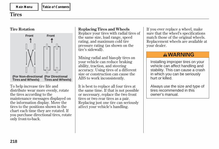
To help increase tire life anddistribute wear more evenly, rotatethe tires according to themaintenance messages displayed onthe information display. Move thetires to the positions shown in thechart each time they are rotated. Ifyou purchase directional tires, rotateonly front-to-back.
Replace your tires with radial tires ofthe same size, load range, speedrating, and maximum cold tirepressure rating (as shown on thetire’s sidewall).
Mixing radial and bias-ply tires onyour vehicle can reduce brakingability, traction, and steeringaccuracy. Using tires of a differentsize or construction can cause theABS to work inconsistently.
It is best to replace all four tires atthe same time. If that is not possibleor necessary, replace the two fronttires or two rear tires as a pair.Replacing just one tire can seriouslyaffect your vehicle’s handling.
If you ever replace a wheel, makesure that the wheel’s specificationsmatch those of the original wheels.Replacement wheels are available atyour dealer.
Tire Rotation Replacing Tires and Wheels
Tires
218
(For Non-directionalTires and Wheels)
Front Front
(For DirectionalTires and Wheels)
Installing improper tires on yourvehicle can affect handling andstability. This can cause a crashin which you can be seriouslyhurt or killed.
Always use the size and type oftires recommended in thisowner’s manual.
05/09/02 12:02:23 31SDR610 0221
+Wheel:
Tire:
See page for DOT tire qualitygrading information, and page
for tire size information.
Tires marked ‘‘M S’’ or ‘‘AllSeason’’ on the sidewall have an all-weather tread design suitable formost winter driving conditions.
For the best performance in snowyor icy conditions, you should installsnow tires or tire chains. They maybe required by local laws undercertain conditions.
If you mount snow tires on yourvehicle, make sure they are radialtires of the same size and load rangeas original tires. Mount snow tires onall four wheels. The tractionprovided by snow tires on dry roadsmay be lower than your original tires.Check with the tire dealer formaximum speed recommendations.
254
253
Wheels and Tires Winter Driving Snow Tires
Tires
Maintenance
219
16 x 6 1/2 JJ
P215/60R16 94V
05/09/02 12:02:31 31SDR610 0222
When installing cables, follow themanufacturer’s instructions, andmount them as tight as you can.Make sure they are not contactingthe brake lines or suspension. Driveslowly with them installed. If youhear them coming into contact withthe body or chassis, stop andinvestigate. Remove them as soon asyou begin driving on cleared roads.
Because your vehicle has limited tireclearance, Honda stronglyrecommends using the chains listedbelow, made by Security ChainCompany (SCC).
Mount tire chains on your tires whenrequired by driving conditions orlocal laws. Install them only on thefront tires.
Cable-types: SCC Radial ChainCH2311T or SCC SC Cable SC1030
Tire Chains
Tires
220
Using the wrong chains, or notproperly installing chains, candamage the brake lines andcause a crash in which you canbe seriously injured or killed.
Follow all instructions in thisowner’s manual regarding theselection and use of tire chains.
05/09/02 12:02:37 31SDR610 0223
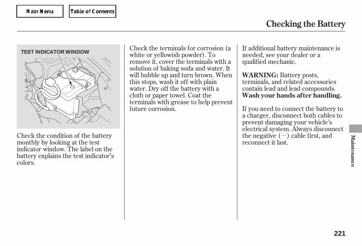
-Check the condition of the batterymonthly by looking at the testindicator window. The label on thebattery explains the test indicator’scolors.
Battery posts,terminals, and related accessoriescontain lead and lead compounds.
If you need to connect the battery toa charger, disconnect both cables toprevent damaging your vehicle’selectrical system. Always disconnectthe negative ( ) cable first, andreconnect it last.
Check the terminals for corrosion (awhite or yellowish powder). Toremove it, cover the terminals with asolution of baking soda and water. Itwill bubble up and turn brown. Whenthis stops, wash it off with plainwater. Dry off the battery with acloth or paper towel. Coat theterminals with grease to help preventfuture corrosion.
If additional battery maintenance isneeded, see your dealer or aqualified mechanic.
WARNING:
Wash your hands after handling.
Checking the Battery
Maintenance
221
TEST INDICATOR WINDOW
05/09/02 12:02:43 31SDR610 0224
If you need to park your vehicle foran extended period (more than 1month), there are several things youshould do to prepare it for storage.Proper preparation helps preventdeterioration and makes it easier toget your vehicle back on the road. Ifpossible, store your vehicle indoors.
Fill the fuel tank.
Change the engine oil and filter.
Wash and dry the exteriorcompletely.
Clean the interior. Make sure thecarpeting, floor mats, etc., arecompletely dry.
Vehicle Storage
Checking the Battery, Vehicle Storage
222
The battery gives off explosivehydrogen gas during normaloperation.
A spark or flame can cause thebattery to explode with enoughforce to kill or seriously hurt you.
Wear protective clothing and aface shield, or have a skilledmechanic do the batterymaintenance.
05/09/02 12:02:49 31SDR610 0225
Support the front wiper bladearms with a folded towel or rag sothey do not touch the windshield.
To minimize sticking, apply asilicone spray lubricant to all doorand trunk seals. Also, apply avehicle body wax to the paintedsurfaces that mate with the doorand trunk seals.
Cover the vehicle with a‘‘breathable’’ cover, one madefrom a porous material such ascotton. Non-porous materials, suchas plastic sheeting, trap moisture,which can damage the paint.
Leave the parking brake off. Putthe transmission in Park.
Block the rear wheels.
If the vehicle is to be stored for alonger period, it should besupported on jackstands so thetires are off the ground.
Leave one window open slightly (ifthe vehicle is being storedindoors).
Reconnect the 12 volt battery anddrive your vehicle every month forabout 30 minutes. This will keepthe IMA battery charged and ingood condition.
Disconnect the 12 volt battery.
Vehicle Storage
Maintenance
223
If this vehicle is unused f or over onemonth, the service lif e of the 144VNickel-Metal Hydride battery will bereduced and the battery may bepermanently damaged.
05/09/22 10:46:38 31SDR610 0226

This section covers the morecommon problems that motoristsexperience with their vehicles. Itgives you information about how tosafely evaluate the problem and whatto do to correct it. If the problem hasstranded you on the side of the road,you may be able to get going again.If not, you will also find instructionson getting your vehicle towed.
......................Compact Spare Tire . 226....................Changing a Flat Tire . 227
.............If the Engine Won’t Start . 230Nothing Happens or theStarter Motor Operates
............................Very Slowly . 230The Starter Operates
................................Normally . 231
................................Jump Starting . 232..............If the Engine Overheats . 234
.........Low Oil Pressure Indicator . 236..........Charging System Indicator . 237
.......Malfunction Indicator Lamp . 237.......................Readiness Codes . 238
...............Brake System Indicator . 239..................Closing the Moonroof . 240
......................Emergency Towing . 241..............................................Fuses . 243
Taking Care of the Unexpected
Taking
Care
ofthe
Unexpected
225
05/09/02 12:03:01 31SDR610 0228
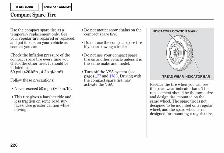
Check the inflation pressure of thecompact spare tire every time youcheck the other tires. It should beinflated to:
Follow these precautions:
Never exceed 50 mph (80 km/h).
This tire gives a harsher ride andless traction on some road sur-faces. Use greater caution whiledriving.
Do not mount snow chains on thecompact spare tire.
Do not use the compact spare tireif you are towing a trailer.
Replace the tire when you can seethe tread wear indicator bars. Thereplacement should be the same sizeand design tire, mounted on thesame wheel. The spare tire is notdesigned to be mounted on a regularwheel, and the spare wheel is notdesigned for mounting a regular tire.
Use the compact spare tire as atemporary replacement only. Getyour regular tire repaired or replaced,and put it back on your vehicle assoon as you can.
Do not use your compact sparetire on another vehicle unless it isthe same make and model.
Turn off the VSA system (seepages and ). Driving withthe compact spare tire mayactivate the VSA.
177 178
Compact Spare Tire
226
INDICATOR LOCATION MARK
TREAD WEAR INDICATOR BAR
60 psi (420 kPa , 4.2 kgf/cm )
05/09/02 12:03:10 31SDR610 0229
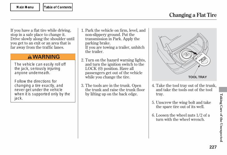
If you have a flat tire while driving,stop in a safe place to change it.Drive slowly along the shoulder untilyou get to an exit or an area that isfar away from the traffic lanes.
Loosen the wheel nuts 1/2 of aturn with the wheel wrench.
Unscrew the wing bolt and takethe spare tire out of its well.
Take the tool tray out of the trunk,and take the tools out of the tooltray.
Park the vehicle on firm, level, andnon-slippery ground. Put thetransmission in Park. Apply theparking brake.If you are towing a trailer, unhitchthe trailer.
Turn on the hazard warning lights,and turn the ignition switch to theLOCK (0) position. Have allpassengers get out of the vehiclewhile you change the tire.
The tools are in the trunk. Openthe trunk and raise the trunk floorby lifting up on the back edge.
5.
4.3.
2.
1.
6.
Changing a Flat Tire
Taking
Care
ofthe
Unexpected
227
TOOL TRAY
The vehicle can easily roll offthe jack, seriously injuringanyone underneath.
Follow the directions forchanging a tire exactly, andnever get under the vehiclewhen it is supported only by thejack.
05/09/02 12:03:18 31SDR610 0230
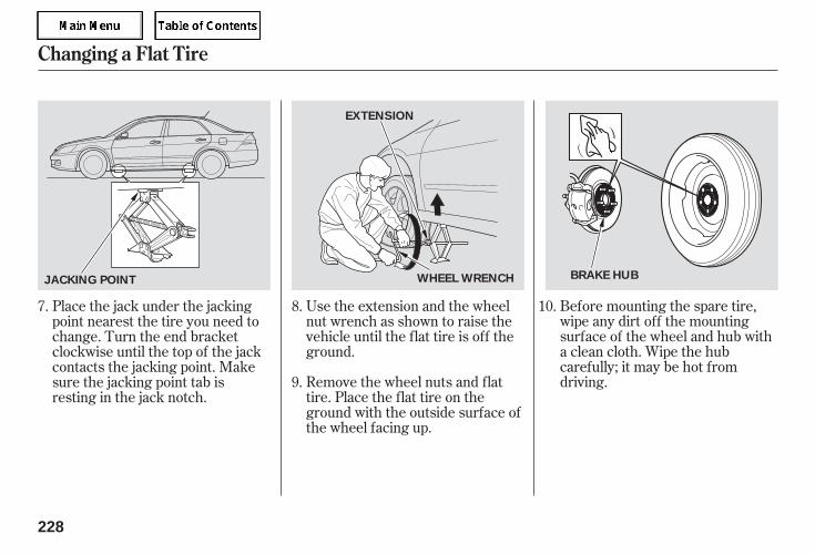
Before mounting the spare tire,wipe any dirt off the mountingsurface of the wheel and hub witha clean cloth. Wipe the hubcarefully; it may be hot fromdriving.Remove the wheel nuts and flat
tire. Place the flat tire on theground with the outside surface ofthe wheel facing up.
Use the extension and the wheelnut wrench as shown to raise thevehicle until the flat tire is off theground.
Place the jack under the jackingpoint nearest the tire you need tochange. Turn the end bracketclockwise until the top of the jackcontacts the jacking point. Makesure the jacking point tab isresting in the jack notch.
8.
9.
7. 10.
Changing a Flat Tire
228
EXTENSION
BRAKE HUBWHEEL WRENCHJACKING POINT
05/09/02 12:03:25 31SDR610 0231
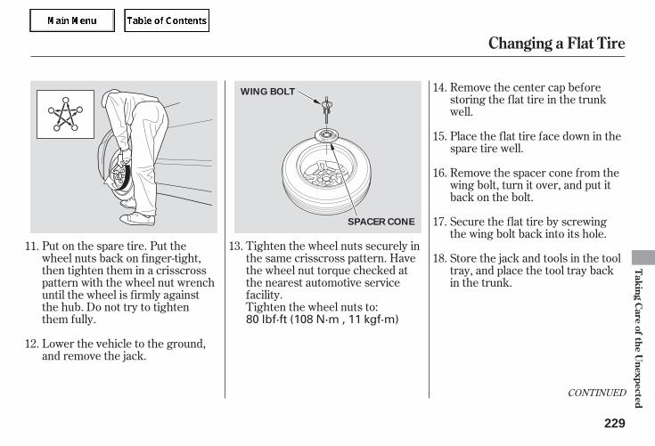
Tighten the wheel nuts securely inthe same crisscross pattern. Havethe wheel nut torque checked atthe nearest automotive servicefacility.Tighten the wheel nuts to:
Put on the spare tire. Put thewheel nuts back on finger-tight,then tighten them in a crisscrosspattern with the wheel nut wrenchuntil the wheel is firmly againstthe hub. Do not try to tightenthem fully.
Lower the vehicle to the ground,and remove the jack.
Remove the center cap beforestoring the flat tire in the trunkwell.
Place the flat tire face down in thespare tire well.
Remove the spacer cone from thewing bolt, turn it over, and put itback on the bolt.
Secure the flat tire by screwingthe wing bolt back into its hole.
Store the jack and tools in the tooltray, and place the tool tray backin the trunk.
11.
12.
13.
14.
15.
16.
17.
18.
CONTINUED
Changing a Flat Tire
Taking
Care
ofthe
Unexpected
229
WING BOLT
SPACER CONE
80 lbf·ft (108 N·m , 11 kgf·m)
05/09/02 12:03:35 31SDR610 0232
Diagnosing why the engine won’tstart falls into two areas, dependingon what you hear when you turn theignition switch to the START (III)position:
When you turn the ignition switch tothe START (III) position, you do nothear the normal noise of the enginetrying to start. You may hear aclicking sound or series of clicks, ornothing at all.
Store the center cap in the trunk.Make sure it does not getscratched or damaged.Lower the trunk floor, then closethe trunk lid.
You can hear the starter motoroperating normally, or the startermotor sounds like it is spinningfaster than normal, but the enginedoes not start up and run.
You hear nothing, or almostnothing. The engine’s startermotor does not operate at all, oroperates very slowly.
Turn the ignition switch to the ON(II) position. Turn on theheadlights, and check theirbrightness. If the headlights arevery dim or do not come on at all,the battery is discharged. See
on page .
Check the transmission interlock.If you have a manual transmission,the clutch pedal must be pushedall the way to the floor or thestarter will not operate. With anautomatic transmission, it must bein Park or neutral.
Check these things:
232
19.
If the Engine Won’t Start Nothing Happens or the StarterMotor Operates Very Slowly
Jump Starting
Changing a Flat Tire, If the Engine Won’t Start
230
Loose items can fly around theinterior in a crash and couldseriously injure the occupants.
Store the wheel, jack, and toolssecurely before driving.
05/09/02 12:03:44 31SDR610 0233
Turn the ignition switch to theSTART (III) position. If theheadlights do not dim, check thecondition of the fuses. If the fusesare OK, there is probablysomething wrong with theelectrical circuit for the ignitionswitch or starter motor. You willneed a qualified technician todetermine the problem (see
on page ).
In this case, the starter motor’sspeed sounds normal, or even fasterthan normal, when you turn theignition switch to the START (III)position, but the engine does not run.
Are you using the proper startingprocedure? Refer to
on page .
Are you using a properly codedkey? An improperly coded key willcause the immobilizer systemindicator in the instrument panelto blink rapidly (see page ).
Do you have fuel? Check the fuelgauge; the low fuel indicator maynot be working.
There may be an electricalproblem, such as no power to thefuel pump. Check all the fuses(see page ).
If the headlights dim noticeably orgo out when you try to start theengine, either the battery is dis-charged or the connections arecorroded. Check the condition ofthe battery connections (see page
). You can then try jumpstarting the vehicle from a boosterbattery (see page ).
If you find nothing wrong, you willneed a qualified mechanic to find theproblem. Seeon page .
241
232
221
165
77
243
241
Emergency Towing
The Starter Operates Normally
Starting theEngine
Emergency Towing
If the Engine Won’t Start
Taking
Care
ofthe
Unexpected
231
05/09/02 12:03:52 31SDR610 0234

+
+
Although this seems like a simpleprocedure, you should take severalprecautions. Open the hood, and check the
physical condition of the battery.In very cold weather, check thecondition of the electrolyte. If itseems slushy or frozen, do not tryjump starting until it thaws.
To jump start your vehicle:
You cannot start your vehicle bypushing or pulling it.
The numbers in the illustration showthe order to connect the jumpercable.
Put the transmission in neutral orPark, and set the parking brake.
Turn off all the electrical acces-sories: heater, A/C, climatecontrol, stereo system, lights, etc.
Connect one jumper cable to thepositive ( ) terminal on yourbattery. Connect the other end tothe positive ( ) terminal on thebooster battery.
1.
2.3.
Jump Starting
232
BOOSTERBATTERY
A battery can explode if you donot follow the correct procedure,seriously injuring anyonenearby.
Keep all sparks, open flames,and smoking materials awayfrom the battery.
If a battery sits in extreme cold, theelectrolyte inside can f reeze.Attempting to jump start with a f rozenbattery can cause it to rupture.
05/09/02 12:04:01 31SDR610 0235
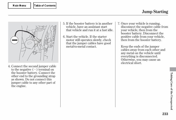
-
Once your vehicle is running,disconnect the negative cable fromyour vehicle, then from thebooster battery. Disconnect thepositive cable from your vehicle,then from the booster battery.
Keep the ends of the jumpercables away from each other andany metal on the vehicle untileverything is disconnected.Otherwise, you may cause anelectrical short.
If the booster battery is in anothervehicle, have an assistant startthat vehicle and run it at a fast idle.
Start the vehicle. If the startermotor still operates slowly, checkthat the jumper cables have goodmetal-to-metal contact.
Connect the second jumper cableto the negative ( ) terminal onthe booster battery. Connect theother end to the grounding strapas shown. Do not connect thisjumper cable to any other part ofthe engine.
7.
6.
5.
4.
Jump Starting
Taking
Care
ofthe
Unexpected
233
05/09/02 12:04:07 31SDR610 0236
If you see steam and/or spraycoming from under the hood, turnoff the engine. Wait until you seeno more signs of steam or spray,then open the hood.
If you do not see steam or spray,leave the engine running, andwatch the temperature gauge. Ifthe high heat is due to overloading,the engine should start to cooldown almost immediately. If itdoes, wait until the temperaturegauge comes down to the midpoint,then continue driving.
If the temperature gauge stays atthe red mark, turn off the engine.
Look for any obvious coolant leaks,such as a split radiator hose.Everything is still extremely hot,so use caution. If you find a leak, itmust be repaired before youcontinue driving (see
on page ).
The pointer of the vehicle’stemperature gauge should stay inthe midrange. If it climbs to the redmark, you should determine thereason (hot day, driving up a steephill, etc.).
If your vehicle overheats, you shouldtake immediate action. The onlyindication may be the temperaturegauge climbing to or above the redmark. Or you may see steam orspray coming from under the hood.
Safely pull to the side of the road.Put the transmission in neutral orPark, and set the parking brake.Turn off all the accessories, andturn on the hazard warning lights.
1.
2.
3.
4.
5.
241Emergency
Towing
If the Engine Overheats
234
Steam and spray from anoverheated engine canseriously scald you.
Do not open the hood if steamis coming out.
Driving with the temperature gaugepointer at the red mark can causeserious damage to the engine.
05/09/02 12:04:15 31SDR610 0237
Using gloves or a large heavycloth, turn the radiator capcounterclockwise, without pushingdown, to the first stop. After thepressure releases, push down onthe cap, and turn it until it comesoff.
Start the engine and set thetemperature control dial tomaximum (climate control toFULL AUTO at 90°F/32°C). Addcoolant to the radiator up to thebase of the filler neck. If you donot have the proper coolantmixture available, you can addplain water. Remember to havethe cooling system drained andrefilled with the proper mixture assoon as you can.
Put the radiator cap back ontightly. Run the engine, and watchthe temperature gauge. If it goesback to the red mark, the engineneeds repair (see
on page ).
If the temperature stays normal,check the coolant level in theradiator reserve tank. If it hasgone down, add coolant to theMAX mark. Put the cap back ontightly.
If you do not find an obvious leak,check the coolant level in theradiator reserve tank. Add coolantif the level is below the MIN mark.
If there was no coolant in thereserve tank, you may need to addcoolant to the radiator. Let theengine cool down until the pointerreaches the middle of the tempera-ture gauge, or lower, before check-ing the radiator.
7.
6. 8.
9.
241
10.
11.
EmergencyTowing
If the Engine Overheats
Taking
Care
ofthe
Unexpected
235
Removing the radiator capwhile the engine is hot cancause the coolant to spray out,seriously scalding you.
Always let the engine andradiator cool down beforeremoving the radiator cap.
05/09/02 12:04:23 31SDR610 0238
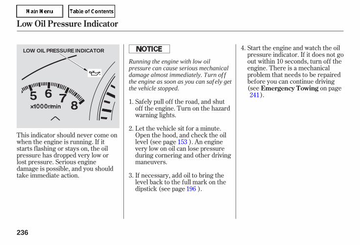
Start the engine and watch the oilpressure indicator. If it does not goout within 10 seconds, turn off theengine. There is a mechanicalproblem that needs to be repairedbefore you can continue driving(see on page
).
This indicator should never come onwhen the engine is running. If itstarts flashing or stays on, the oilpressure has dropped very low orlost pressure. Serious enginedamage is possible, and you shouldtake immediate action. If necessary, add oil to bring the
level back to the full mark on thedipstick (see page ).
Let the vehicle sit for a minute.Open the hood, and check the oillevel (see page ). An enginevery low on oil can lose pressureduring cornering and other drivingmaneuvers.
Safely pull off the road, and shutoff the engine. Turn on the hazardwarning lights.
1.
2.
3.
4.
153
196
241Emergency Towing
Low Oil Pressure Indicator
236
LOW OIL PRESSURE INDICATOR
Running the engine with low oilpressure can cause serious mechanicaldamage almost immediately. Turn of fthe engine as soon as you can saf ely getthe vehicle stopped.
05/09/02 12:04:29 31SDR610 0239
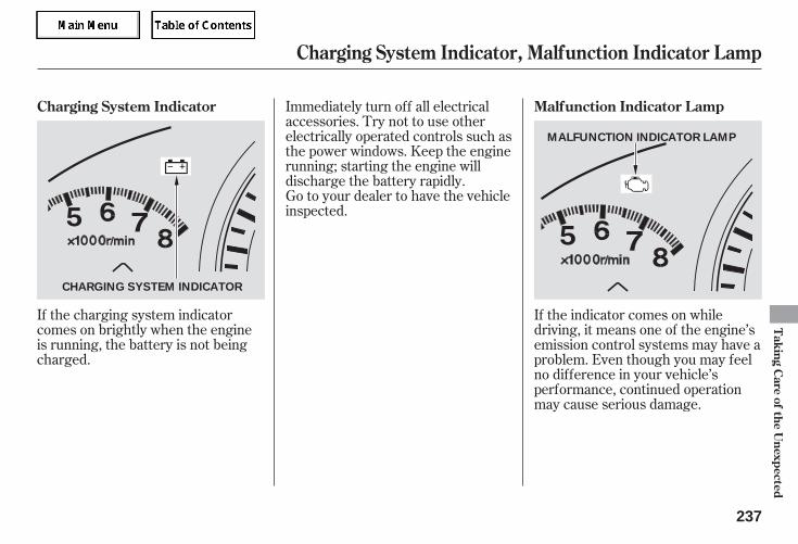
If the charging system indicatorcomes on brightly when the engineis running, the battery is not beingcharged.
If the indicator comes on whiledriving, it means one of the engine’semission control systems may have aproblem. Even though you may feelno difference in your vehicle’sperformance, continued operationmay cause serious damage.
Immediately turn off all electricalaccessories. Try not to use otherelectrically operated controls such asthe power windows. Keep the enginerunning; starting the engine willdischarge the battery rapidly.Go to your dealer to have the vehicleinspected.
Malfunction Indicator LampCharging System Indicator
Charging System Indicator, Malfunction Indicator Lamp
Taking
Care
ofthe
Unexpected
237
CHARGING SYSTEM INDICATOR
MALFUNCTION INDICATOR LAMP
05/09/02 12:04:36 31SDR610 0240
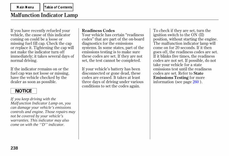
If the indicator remains on or thefuel cap was not loose or missing,have the vehicle checked by thedealer as soon as possible.
If your vehicle’s battery has beendisconnected or gone dead, thesecodes are erased. It takes at leastthree days of driving under variousconditions to set the codes again.
Your vehicle has certain ‘‘readinesscodes’’ that are part of the on-boarddiagnostics for the emissionssystems. In some states, part of theemissions testing is to make surethese codes are set. If they are notset, the test cannot be completed.
To check if they are set, turn theignition switch to the ON (II)position, without starting the engine.The malfunction indicator lamp willcome on for 20 seconds. If it thengoes off, the readiness codes are set.If it blinks five times, the readinesscodes are not set. If possible, do nottake your vehicle for a stateemissions test until the readinesscodes are set. Refer to
for moreinformation (see page ).
If you have recently refueled yourvehicle, the cause of this indicatorcoming on could be a loose ormissing fuel fill cap. Check the capor replace it. Tightening the cap willnot make the indicator turn offimmediately; it takes several days ofnormal driving.
260
Readiness Codes
StateEmissions Testing
Malfunction Indicator Lamp
238
If you keep driving with theMalf unction Indicator Lamp on, youcan damage your vehicle’s emissionscontrols and engine. Those repairs maynot be covered by your vehicle’swarranties. This indicator may alsocome on with the ‘‘D’’ indicator.
05/09/02 12:04:42 31SDR610 0241
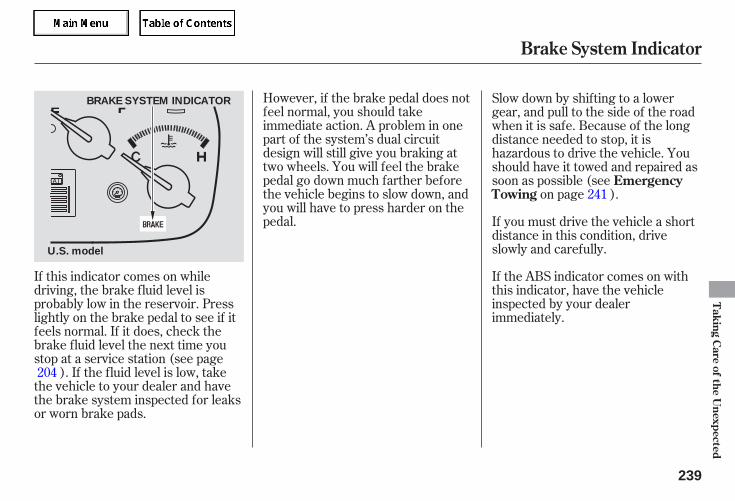
However, if the brake pedal does notfeel normal, you should takeimmediate action. A problem in onepart of the system’s dual circuitdesign will still give you braking attwo wheels. You will feel the brakepedal go down much farther beforethe vehicle begins to slow down, andyou will have to press harder on thepedal.
If the ABS indicator comes on withthis indicator, have the vehicleinspected by your dealerimmediately.
If this indicator comes on whiledriving, the brake fluid level isprobably low in the reservoir. Presslightly on the brake pedal to see if itfeels normal. If it does, check thebrake fluid level the next time youstop at a service station (see page
). If the fluid level is low, takethe vehicle to your dealer and havethe brake system inspected for leaksor worn brake pads.
If you must drive the vehicle a shortdistance in this condition, driveslowly and carefully.
Slow down by shifting to a lowergear, and pull to the side of the roadwhen it is safe. Because of the longdistance needed to stop, it ishazardous to drive the vehicle. Youshould have it towed and repaired assoon as possible (see
on page ).241
204
EmergencyTowing
Brake System Indicator
Taking
Care
ofthe
Unexpected
239
BRAKE SYSTEM INDICATOR
U.S. model
05/09/02 12:04:48 31SDR610 0242
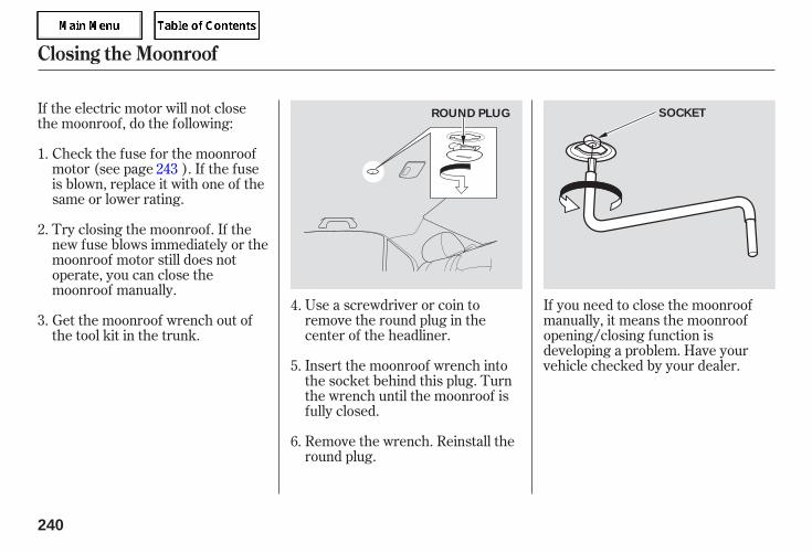
Use a screwdriver or coin toremove the round plug in thecenter of the headliner.
Insert the moonroof wrench intothe socket behind this plug. Turnthe wrench until the moonroof isfully closed.
Remove the wrench. Reinstall theround plug.
If you need to close the moonroofmanually, it means the moonroofopening/closing function isdeveloping a problem. Have yourvehicle checked by your dealer.
If the electric motor will not closethe moonroof, do the following:
Check the fuse for the moonroofmotor (see page ). If the fuseis blown, replace it with one of thesame or lower rating.
Try closing the moonroof. If thenew fuse blows immediately or themoonroof motor still does notoperate, you can close themoonroof manually.
Get the moonroof wrench out ofthe tool kit in the trunk.
5.
6.
4.3.
1.
2.
243
Closing the Moonroof
240
ROUND PLUG SOCKET
05/09/02 12:04:56 31SDR610 0243
-
-
If your vehicle needs to be towed,call a professional towing service oran organization. Never tow yourvehicle with just a rope or chain. It isvery dangerous.
There are two ways to tow yourvehicle:
The operatorloads your vehicle on the back of atruck.
The towtruck uses two pivoting arms that gounder the tires (front or rear) and liftthem off the ground. The other twotires remain on the ground.
Release the parking brake.Start the engine.Shift to D, then to N.
If, due to damage, your vehicle mustbe towed with the front wheels onthe ground, do the following:
Turn off the engine.Leave the ignition switch in theACCESSORY (I) position so thesteering wheel does not lock.
CONTINUED
Flat-bed Equipment
Wheel-lif t Equipment
This is the best way to trans-port your vehicle.
This isan acceptable way to tow yourvehicle.
Emergency Towing
Taking
Care
ofthe
Unexpected
241
Improper towing preparation willdamage the transmission. Follow theabove procedure exactly. If you cannotshif t the transmission or start theengine, your vehicle must betransported with the f ront wheels of fthe ground.
05/09/02 12:05:05 31SDR610 0244
With the front wheels on the ground,it is best to tow the vehicle no fartherthan 50 miles (80 km), and keep thespeed below 35 mph (55 km/h).
If your vehicle is equipped with afront spoiler, remove it beforetowing so it is not damaged.
Emergency Towing
242
The steering system can be damaged ifthe steering wheel is locked. Leave theignition switch in the ACCESSORY (I)position, and make sure the steeringwheel turns f reely bef ore you begintowing.
Trying to lif t or tow your vehicle by thebumpers will cause serious damage.The bumpers are not designed tosupport the vehicle’s weight.
05/09/02 12:05:09 31SDR610 0245
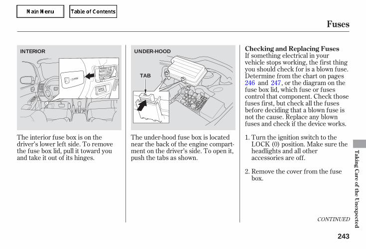
The interior fuse box is on thedriver’s lower left side. To removethe fuse box lid, pull it toward youand take it out of its hinges.
The under-hood fuse box is locatednear the back of the engine compart-ment on the driver’s side. To open it,push the tabs as shown.
If something electrical in yourvehicle stops working, the first thingyou should check for is a blown fuse.Determine from the chart on pages
and , or the diagram on thefuse box lid, which fuse or fusescontrol that component. Check thosefuses first, but check all the fusesbefore deciding that a blown fuse isnot the cause. Replace any blownfuses and check if the device works.
Turn the ignition switch to theLOCK (0) position. Make sure theheadlights and all otheraccessories are off.
Remove the cover from the fusebox.
1.
2.
246 247
CONTINUED
Checking and Replacing Fuses
Fuses
Taking
Care
ofthe
Unexpected
243
INTERIOR UNDER-HOOD
TAB
05/09/02 12:05:17 31SDR610 0246
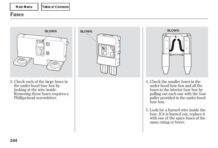
Check each of the large fuses inthe under-hood fuse box bylooking at the wire inside.Removing these fuses requires aPhillips-head screwdriver.
Check the smaller fuses in theunder-hood fuse box and all thefuses in the interior fuse box bypulling out each one with the fusepuller provided in the under-hoodfuse box.
Look for a burned wire inside thefuse. If it is burned out, replace itwith one of the spare fuses of thesame rating or lower.
3. 4.
5.
Fuses
244
BLOWN BLOWN BLOWN
05/09/02 12:05:23 31SDR610 0247
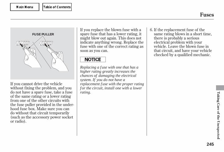
If you cannot drive the vehiclewithout fixing the problem, and youdo not have a spare fuse, take a fuseof the same rating or a lower ratingfrom one of the other circuits withthe fuse puller provided in the under-hood fuse box. Make sure you cando without that circuit temporarily(such as the accessory power socketor radio).
If you replace the blown fuse with aspare fuse that has a lower rating, itmight blow out again. This does notindicate anything wrong. Replace thefuse with one of the correct rating assoon as you can.
If the replacement fuse of thesame rating blows in a short time,there is probably a seriouselectrical problem with yourvehicle. Leave the blown fuse inthat circuit, and have your vehiclechecked by a qualified mechanic.
6.
Fuses
Taking
Care
ofthe
Unexpected
245
FUSE PULLER
Replacing a f use with one that has ahigher rating greatly increases thechances of damaging the electricalsystem. If you do not have areplacement f use with the proper ratingf or the circuit, install one with a lowerrating.
05/09/02 12:05:29 31SDR610 0248
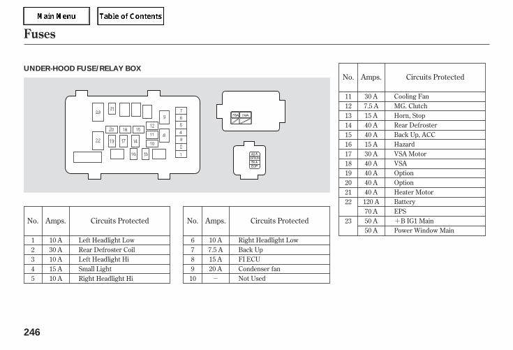
-
+No. No.Amps. Circuits Protected
No.
Circuits ProtectedAmps.
Amps. Circuits Protected
12345
6789
10
10 A30 A10 A15 A10 A
Left Headlight LowRear Defroster CoilLeft Headlight HiSmall LightRight Headlight Hi
111213141516171819202122
23
Right Headlight LowBack UpFI ECUCondenser fanNot Used
10 A7.5 A15 A20 A
30 A7.5 A15 A40 A40 A15 A30 A40 A40 A40 A40 A
120 A70 A50 A50 A
Cooling FanMG. ClutchHorn, StopRear DefrosterBack Up, ACCHazardVSA MotorVSAOptionOptionHeater MotorBatteryEPS
B IG1 MainPower Window Main
Fuses
246
UNDER-HOOD FUSE/RELAY BOX
05/09/02 12:05:36 31SDR610 0249
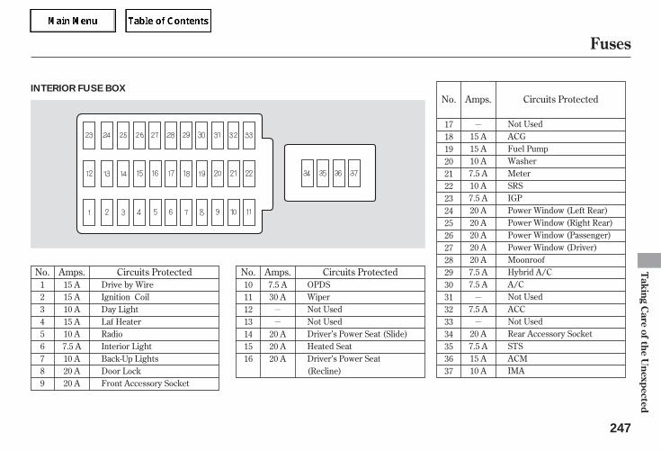
-
-
-
-
-
No.
No. Amps.Amps.No. Circuits Protected Circuits Protected
Amps. Circuits Protected
171819202122232425262728293031323334353637
10111213141516
7.5 A30 A
20 A20 A20 A
15 A15 A10 A15 A10 A7.5 A10 A20 A20 A
123456789
Drive by WireIgnition CoilDay LightLaf HeaterRadioInterior LightBack-Up LightsDoor LockFront Accessory Socket
OPDSWiperNot UsedNot UsedDriver’s Power Seat (Slide)Heated SeatDriver’s Power Seat(Recline)
15 A15 A10 A7.5 A10 A7.5 A20 A20 A20 A20 A20 A7.5 A7.5 A
7.5 A
20 A7.5 A15 A10 A
Not UsedACGFuel PumpWasherMeterSRSIGPPower Window (Left Rear)Power Window (Right Rear)Power Window (Passenger)Power Window (Driver)MoonroofHybrid A/CA/CNot UsedACCNot UsedRear Accessory SocketSTSACMIMA
Fuses
Taking
Care
ofthe
Unexpected
247
INTERIOR FUSE BOX
05/09/02 12:05:44 31SDR610 0250

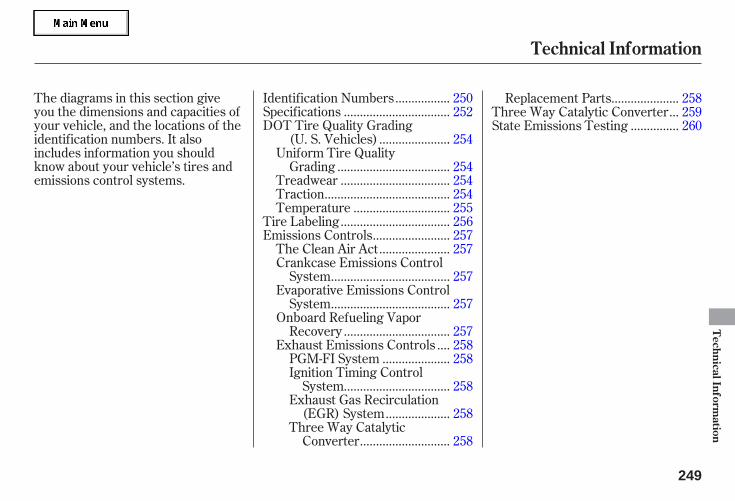
The diagrams in this section giveyou the dimensions and capacities ofyour vehicle, and the locations of theidentification numbers. It alsoincludes information you shouldknow about your vehicle’s tires andemissions control systems.
................Identification Numbers . 250................................Specifications . 252
DOT Tire Quality Grading.....................(U. S. Vehicles) . 254
Uniform Tire Quality..................................Grading . 254.................................Treadwear . 254
......................................Traction . 254.............................Temperature . 255
.................................Tire Labeling . 256.......................Emissions Controls . 257.....................The Clean Air Act . 257
Crankcase Emissions Control....................................System . 257
Evaporative Emissions Control....................................System . 257
Onboard Refueling Vapor................................Recovery . 257
...Exhaust Emissions Controls . 258....................PGM-FI System . 258
Ignition Timing Control................................System . 258
Exhaust Gas Recirculation...................(EGR) System . 258
Three Way Catalytic...........................Converter . 258
....................Replacement Parts . 258..Three Way Catalytic Converter . 259
..............State Emissions Testing . 260
Technical Information
TechnicalInform
ation
249
05/09/02 12:05:50 31SDR610 0252
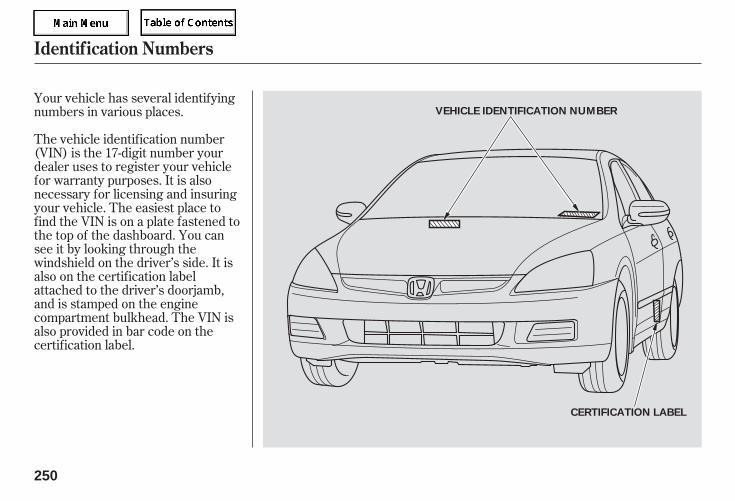
Your vehicle has several identifyingnumbers in various places.
The vehicle identification number(VIN) is the 17-digit number yourdealer uses to register your vehiclefor warranty purposes. It is alsonecessary for licensing and insuringyour vehicle. The easiest place tofind the VIN is on a plate fastened tothe top of the dashboard. You cansee it by looking through thewindshield on the driver’s side. It isalso on the certification labelattached to the driver’s doorjamb,and is stamped on the enginecompartment bulkhead. The VIN isalso provided in bar code on thecertification label.
Identif ication Numbers
250
VEHICLE IDENTIFICATION NUMBER
CERTIFICATION LABEL
05/09/02 12:05:54 31SDR610 0253
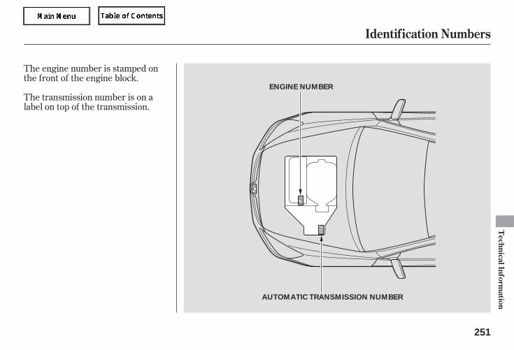
The transmission number is on alabel on top of the transmission.
The engine number is stamped onthe front of the engine block.
Identif ication Numbers
TechnicalInform
ation
251
AUTOMATIC TRANSMISSION NUMBER
ENGINE NUMBER
05/09/02 12:05:58 31SDR610 0254
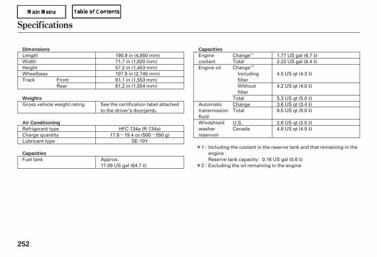
- -
*
*
*
*
Specifications
252
Dimensions
Weights
Air Conditioning
Capacities
Capacities
HFC-134a (R-134a)17.6 19.4 oz (500 550 g)
107.9 in (2,740 mm)61.1 in (1,553 mm)61.2 in (1,554 mm)
LengthWidthHeightWheelbaseTrack
Gross vehicle weight rating See the certification label attachedto the driver’s doorjamb.
SE-10Y
Refrigerant typeCharge quantityLubricant type
Fuel tank17.09 US gal (64.7 )
EnginecoolantEngine oil
AutomatictransmissionfluidWindshieldwasherreservoir
1.77 US gal (6.7 )2.22 US gal (8.4 )
4.5 US qt (4.3 )
4.2 US qt (4.0 )
5.3 US qt (5.0 )
2.6 US qt (2.5 )4.8 US qt (4.5 )
Including the coolant in the reserve tank and that remaining in theengineReserve tank capacity: 0.16 US gal (0.6 )Excluding the oil remaining in the engine
3.6 US qt (3.4 )8.5 US qt (8.0 )
190.9 in (4,850 mm)71.7 in (1,820 mm)57.2 in (1,453 mm)
Approx.
FrontRear
1 :
2 :
ChangeTotalChange
IncludingfilterWithoutfilter
TotalChangeTotal
U.S.Canada
1
2
05/09/02 12:06:11 31SDR610 0255
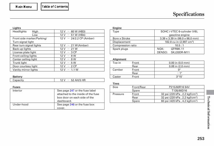
-
---
--------
-
Specifications
TechnicalInform
ation
253
Engine
Alignment
Tires
Lights
Battery
Fuses
12 V 60 W (HB3)12 V 51 W (HB4)
12 V 21 W
12 V 24/2.2 CP
SOHC i-VTEC 6-cylinder (V6),gasoline engine
3.39 x 3.39 in (86.0 x 86.0 mm)182.8 cu-in (2,997 cm )
10.5 : 1IZFR6K-11SKJ20DR-M11
Type
Bore x StrokeDisplacementCompression ratioSpark plugs
Toe-in
Camber
Caster
0.00 in (0.0 mm)0.08 in (2.0 mm)
0°1°
3°15’
Size
Pressure
P215/60R16 94VT135/80D16
32 psi (220 kPa , 2.2 kgf/cm )32 psi (220 kPa , 2.2 kgf/cm )60 psi (420 kPa , 4.2 kgf/cm )
Headlights
Front side marker/Parking/Turn signal lightRear turn signal lightsBack-up lightsLicense plate lightFront ceiling lightsCenter ceiling lightTrunk lightDoor courtesy lightVanity mirror lights
12 V12 V12 V12 V12 V12 V12 V
21 W3 CP8 W8 W5 W2 CP1.1 W
Capacity
Interior
Under-hood
12 V 52 AH/5 HR
See page 247 or the fuse labelattached to the inside of the fusebox door on each side of thedashboard.See page 246 or the fuse boxcover.
FrontRearFrontRearFront
HighLow
NGK:DENSO:
Front/RearSpareFrontRearSpare
(Amber)
(Amber)
05/09/02 12:06:32 31SDR610 0256
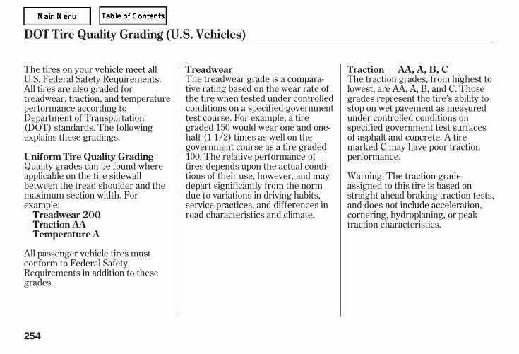
-
Quality grades can be found whereapplicable on the tire sidewallbetween the tread shoulder and themaximum section width. Forexample:
The treadwear grade is a compara-tive rating based on the wear rate ofthe tire when tested under controlledconditions on a specified governmenttest course. For example, a tiregraded 150 would wear one and one-half (1 1/2) times as well on thegovernment course as a tire graded100. The relative performance oftires depends upon the actual condi-tions of their use, however, and maydepart significantly from the normdue to variations in driving habits,service practices, and differences inroad characteristics and climate.
The traction grades, from highest tolowest, are AA, A, B, and C. Thosegrades represent the tire’s ability tostop on wet pavement as measuredunder controlled conditions onspecified government test surfacesof asphalt and concrete. A tiremarked C may have poor tractionperformance.
Warning: The traction gradeassigned to this tire is based onstraight-ahead braking traction tests,and does not include acceleration,cornering, hydroplaning, or peaktraction characteristics.
All passenger vehicle tires mustconform to Federal SafetyRequirements in addition to thesegrades.
The tires on your vehicle meet allU.S. Federal Safety Requirements.All tires are also graded fortreadwear, traction, and temperatureperformance according toDepartment of Transportation(DOT) standards. The followingexplains these gradings.
Uniform Tire Quality Grading
Treadwear 200Traction AATemperature A
Treadwear Traction AA, A, B, C
DOT Tire Quality Grading (U.S. Vehicles)
254
05/09/02 12:06:40 31SDR610 0257
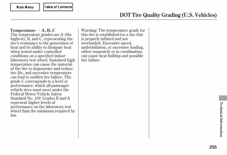
- Warning: The temperature grade forthis tire is established for a tire thatis properly inflated and notoverloaded. Excessive speed,underinflation, or excessive loading,either separately or in combination,can cause heat buildup and possibletire failure.
The temperature grades are A (thehighest), B, and C, representing thetire’s resistance to the generation ofheat and its ability to dissipate heatwhen tested under controlledconditions on a specified indoorlaboratory test wheel. Sustained hightemperature can cause the materialof the tire to degenerate and reducetire life, and excessive temperaturecan lead to sudden tire failure. Thegrade C corresponds to a level ofperformance, which all passengervehicle tires must meet under theFederal Motor Vehicle SafetyStandard No. 109. Grades B and Arepresent higher levels ofperformance on the laboratory testwheel than the minimum required bylaw.
Temperature A, B, C
DOT Tire Quality Grading (U.S. Vehicles)
TechnicalInform
ation
255
05/09/02 12:06:44 31SDR610 0258
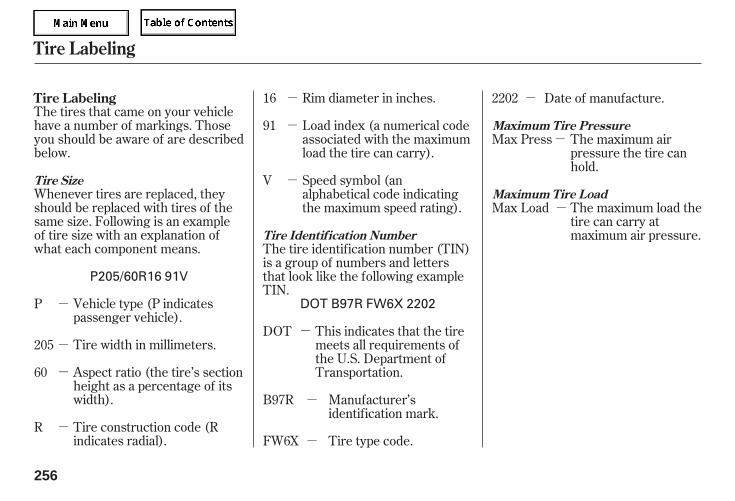
-
-
-
-
-
-
-
-
-
-
-
-
-Whenever tires are replaced, theyshould be replaced with tires of thesame size. Following is an exampleof tire size with an explanation ofwhat each component means.
The tires that came on your vehiclehave a number of markings. Thoseyou should be aware of are describedbelow.
Vehicle type (P indicatespassenger vehicle).
Tire width in millimeters.
Aspect ratio (the tire’s sectionheight as a percentage of itswidth).
Tire construction code (Rindicates radial).
Rim diameter in inches.
Load index (a numerical codeassociated with the maximumload the tire can carry).
Speed symbol (analphabetical code indicatingthe maximum speed rating).
The tire identification number (TIN)is a group of numbers and lettersthat look like the following exampleTIN.
This indicates that the tiremeets all requirements ofthe U.S. Department ofTransportation.
Manufacturer’sidentification mark.
Tire type code.
Date of manufacture.
The maximum airpressure the tire canhold.
The maximum load thetire can carry atmaximum air pressure.
P
R
V
16
DOT
B97R
FW6X
2202
205
60
91Max Press
Max Load
Tire Labeling
Tire Size
Tire Identif ication Number
Maximum Tire Pressure
Maximum Tire Load
Tire Labeling
256
P205/60R16 91V
DOT B97R FW6X 2202
05/09/02 12:07:00 31SDR610 0259
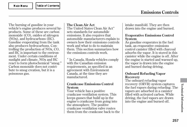
*
*
The burning of gasoline in yourvehicle’s engine produces several by-products. Some of these are carbonmonoxide (CO), oxides of nitrogen(NOx), and hydrocarbons (HC).Gasoline evaporating from the tankalso produces hydrocarbons. Con-trolling the production of NOx, CO,and HC is important to the environ-ment. Under certain conditions ofsunlight and climate, NOx and HCreact to form photochemical ‘‘smog.’’Carbon monoxide does not contri-bute to smog creation, but it is apoisonous gas.
The United States Clean Air Actsets standards for automobileemissions. It also requires thatautomobile manufacturers explain toowners how their emissions controlswork and what to do to maintainthem. This section summarizes howthe emissions controls work.
In Canada, Honda vehicles complywith the Canadian emissionrequirements, as specified in anagreement with EnvironmentCanada, at the time they aremanufactured.
Your vehicle has a positivecrankcase ventilation system. Thiskeeps gasses that build up in theengine’s crankcase from going intothe atmosphere. The positivecrankcase ventilation valve routesthem from the crankcase back to the
intake manifold. They are thendrawn into the engine and burned.
As gasoline evaporates in the fueltank, an evaporative emissionscontrol canister filled with charcoaladsorbs the vapor. It is stored in thiscanister while the engine is off. Afterthe engine is started and warmed up,the vapor is drawn into the engineand burned during driving.
The onboard refueling vaporrecovery (ORVR) system capturesthe fuel vapors during refueling. Thevapors are adsorbed in a canisterfilled with activated carbon. Whiledriving, the fuel vapors are drawninto the engine and burned off.
The Clean Air Act
Crankcase Emissions ControlSystem
Evaporative Emissions ControlSystem
Onboard Refueling VaporRecovery
Emissions Controls
TechnicalInform
ation
257
05/09/02 12:07:08 31SDR610 0260
The exhaust emissions controlsinclude four systems: PGM-FI,ignition timing control, exhaust gasrecirculation, and three way catalyticconverter. These four systems worktogether to control the engine’scombustion and minimize theamount of HC, CO, and NOx thatcome out the tailpipe. The exhaustemissions control systems areseparate from the crankcase andevaporative emissions controlsystems.
The emissions control systems aredesigned and certified to work to-gether in reducing emissions tolevels that comply with the Clean AirAct. To make sure the emissionsremain low, you should use only newHonda replacement parts or theirequivalent for repairs. Using lowerquality parts may increase theemissions from your vehicle.
The emissions control systems arecovered by warranties separate fromthe rest of your vehicle. Read yourwarranty manual for more informa-tion.The PGM-FI system uses sequential
multiport fuel injection.It has three subsystems: air intake,engine control, and fuel control. Thepowertrain control module (PCM)uses various sensors to determinehow much air is going into theengine. It then controls how muchfuel to inject under all operatingconditions.
This system constantly adjusts theignition timing, reducing the amountof HC, CO, and NOx produced.
The exhaust gas recirculation (EGR)system takes some of the exhaustgas and routes it back into the intakemanifold. Adding exhaust gas to theair/fuel mixture reduces the amountof NOx produced when the fuel isburned.
The three way catalytic converter isin the exhaust system. Throughchemical reactions, it converts HC,CO, and NOx in the engine’s exhaustto carbon dioxide (CO ), nitrogen(N ), and water vapor.
2
2
Exhaust Emissions Controls Replacement Parts
PGM-FI System
Ignition Timing Control System
Exhaust Gas Recirculation (EGR)System
Three Way Catalytic Converter
Emissions Controls
258
05/09/02 12:07:17 31SDR610 0261
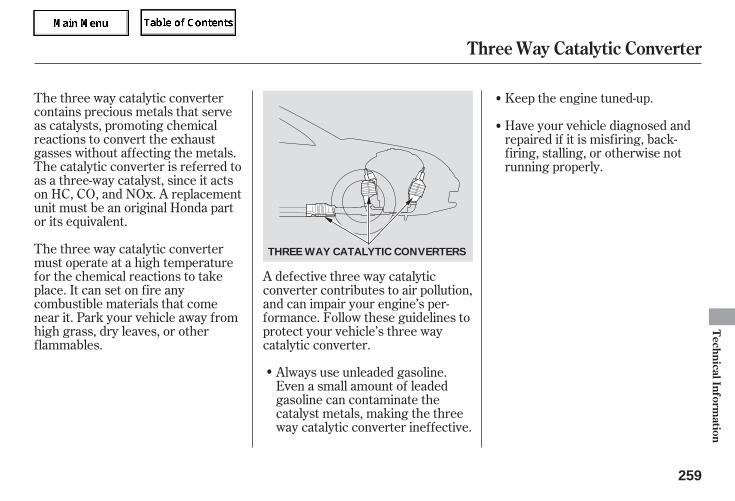
The three way catalytic convertercontains precious metals that serveas catalysts, promoting chemicalreactions to convert the exhaustgasses without affecting the metals.The catalytic converter is referred toas a three-way catalyst, since it actson HC, CO, and NOx. A replacementunit must be an original Honda partor its equivalent.
Always use unleaded gasoline.Even a small amount of leadedgasoline can contaminate thecatalyst metals, making the threeway catalytic converter ineffective.
The three way catalytic convertermust operate at a high temperaturefor the chemical reactions to takeplace. It can set on fire anycombustible materials that comenear it. Park your vehicle away fromhigh grass, dry leaves, or otherflammables.
A defective three way catalyticconverter contributes to air pollution,and can impair your engine’s per-formance. Follow these guidelines toprotect your vehicle’s three waycatalytic converter.
Keep the engine tuned-up.
Have your vehicle diagnosed andrepaired if it is misfiring, back-firing, stalling, or otherwise notrunning properly.
Three Way Catalytic Converter
TechnicalInform
ation
259
THREE WAY CATALYTIC CONVERTERS
05/09/02 12:07:23 31SDR610 0262
Make sure the gas tank is nearly,but not completely, full (around3/4).
Without touching the acceleratorpedal, start the engine, and let itidle for 20 seconds.
If you take your vehicle for a stateemissions test shortly after thebattery has been disconnected orgone dead, it may not pass the test.This is because of certain ‘‘readinesscodes’’ that must be set in the on-board diagnostics for the emissionssystems. These codes are erasedwhen the battery is disconnected,and set again only after several daysof driving under a variety ofconditions.
If the testing facility determines thatthe readiness codes are not set, youwill be requested to return at a laterdate to complete the test. If you mustget the vehicle retested within thenext two or three days, you cancondition the vehicle for retesting bydoing the following.
Keep the vehicle in Park. Increasethe engine speed to 2,000 rpm, andhold it there until the temperaturegauge rises to at least 1/4 of thescale (about 3 minutes).
Make sure the vehicle has beenparked with the engine off for 6hours or more.
Make sure the ambienttemperature is between 40° and95°F.
Testing of Readiness Codes
State Emissions Testing
260
05/09/02 12:07:29 31SDR610 0263
Then drive in city/suburbantraffic for at least 10 minutes.When traffic conditions allow, letthe vehicle coast for severalseconds without using theaccelerator pedal or the brakepedal.
If the testing facility determines thereadiness codes are still not set, seeyour dealer.
Select a nearby lightly traveledmajor highway where you canmaintain a speed of 50 to 60 mph(80 to 97 km/h) for at least 20minutes. Drive on the highway inD. Do not use the cruise control.When traffic allows, drive for 90seconds without moving theaccelerator pedal. (Vehicle speedmay vary slightly; this is okay.) Ifyou cannot do this for acontinuous 90 seconds because oftraffic conditions, drive for at least30 seconds, then repeat it twomore times (for a total of 90seconds).
State Emissions Testing
TechnicalInform
ation
261
05/09/02 12:07:33 31SDR610 0264

....Customer Service Information . 264....................Warranty Coverages . 265
Reporting Safety Defects............................(U.S. Vehicle) . 266
.....................Authorized Manuals . 267
Warranty and Customer Relations
Warranty
andC
ustomer
Relations
263
05/09/02 12:07:39 31SDR610 0266
Honda dealership personnel aretrained professionals. They shouldbe able to answer all your questions.If you encounter a problem that yourdealership does not solve to yoursatisfaction, please discuss it withthe dealership’s management. Theservice manager or general managercan help. Almost all problems aresolved in this way.
If you are dissatisfied with thedecision made by the dealership’smanagement, contact your HondaCustomer Service Office.
U.S. Owners:
Canadian Owners:
In Puerto Rico and the U.S. VirginIslands:
When you call or write, please giveus this information:
Vehicle identification number (seepage )
Name and address of the dealerwho services your vehicle
Date of purchase
Mileage on your vehicle
Your name, address, andtelephone number
A detailed description of theproblem
Name of the dealer who sold thevehicle to you
250
Customer Service Information
264
CUSTOMER RELATIONS
RELATIONS AVEC LA CLIENTÉLE
American Honda Motor Co., Inc.Automobile Customer ServiceMail Stop 500-2N-7A1919 Torrance BoulevardTorrance, California 90501-2746
Tel: (800) 999-1009
Honda Canada Inc.715 Milner AvenueToronto, ONM1B 2K8
Tel: 1-888-9-HONDA-9Fax: Toll-free 1-877-939-0909
Toronto (416) 287-4776
Bella InternationalP.O. Box 190816
San Juan, Puerto Rico 00919-0816
Tel: (787) 250-4327
05/09/02 12:07:47 31SDR610 0267
-
-
-
-
-
-
-
-
-
Your new vehicle is covered by thesewarranties:
covers your new vehicle, except forthe battery, emissions controlsystems, and accessories, againstdefects in materials andworkmanship.
provides proratedcoverage for a replacement batterypurchased from your dealer.
these twowarranties cover your vehicle’semissions control systems. Time,mileage, and coverage areconditional. Please read yourwarranty booklet for exactinformation.
a seatbelt that fails to function properly iscovered for the useful life of thevehicle.
all exterior body panels arecovered for rust-through from theinside for the specified time periodwith no mileage limit.
Honda accessories are coveredunder this warranty. Time andmileage limits depend on the type ofaccessory and other factors. Pleaseread your warranty booklet fordetails.
covers all Hondareplacement parts against defects inmaterials and workmanship.
providescoverage for as long as the pur-chaser of the muffler owns thevehicle.
this warranty gives upto 100 percent credit toward areplacement battery.
Restrictions and exclusions apply toall these warranties. Please read the2006 Honda warranty informationbooklet that came with your vehiclefor precise information on warrantycoverages. Your vehicle’s originaltires are covered by theirmanufacturer. Tire warrantyinformation is in a separate booklet.
Please refer to the 2006 warrantymanual that came with your vehicle.
Warranty Coverages
U.S. Owners
Canadian Owners
New Vehicle Limited Warranty
Replacement Battery LimitedWarranty
Emissions Control Systems DefectsWarranty and EmissionsPerformance Warranty
Seat Belt Limited Warranty
Rust Perforation Limited Warranty
Accessory Limited Warranty
Replacement Parts LimitedWarranty
Replacement Muffler LifetimeLimited Warranty
Original Equipment Battery LimitedWarranty
Warranty
andC
ustomer
Relations
265
05/09/02 12:07:57 31SDR610 0268
If NHTSA receives similar com-plaints, it may open an investigation,and if it finds that a safety defectexists in a group of vehicles, it mayorder a recall and remedy campaign.However, NHTSA cannot becomeinvolved in individual problemsbetween you, your dealer, orAmerican Honda Motor Co., Inc.
If you believe that your vehicle has adefect which could cause a crash orcould cause injury or death, youshould immediately inform theNational Highway Traffic SafetyAdministration (NHTSA), in additionto notifying American Honda MotorCo., Inc.
To contact NHTSA, you may call theVehicle Safety Hotline toll-free at 1-800-327-4236 (TTY 1-800-424-9153);go to http://www.safercar.gov; orwrite to: Administrator, NHTSA, 400Seventh Street, SW., Washington,DC 20590.You can also obtain otherinformation about motor vehiclesafety from http://www.safercar.gov.
Reporting Safety Defects (U.S. Vehicles)
266
05/09/02 12:08:01 31SDR610 0269
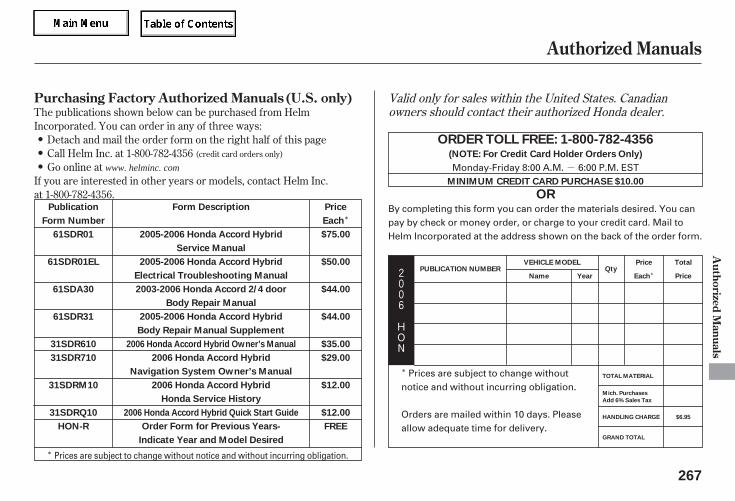
-
*
*
*
*2006
HON
The publications shown below can be purchased from HelmIncorporated. You can order in any of three ways:
Detach and mail the order form on the right half of this pageCall Helm Inc. at 1-800-782-4356Go online at
If you are interested in other years or models, contact Helm Inc.at 1-800-782-4356.
(credit card orders only)
Valid only for sales within the United States. Canadianowners should contact their authorized Honda dealer.
Authorized Manuals
Purchasing Factory Authorized Manuals (U.S. only)
Authorized
Manuals
267
ORDER TOLL FREE: 1-800-782-4356
OR
(NOTE: For Credit Card Holder Orders Only)
MINIMUM CREDIT CARD PURCHASE $10.00
Publication
Form Number
61SDR01
61SDR01EL
61SDA30
61SDR31
31SDR610
31SDR710
31SDRM10
31SDRQ10
HON-R
Price
Each
$75.00
$50.00
$44.00
$44.00
$35.00
$29.00
$12.00
$12.00
FREE
Form Description
2005-2006 Honda Accord Hybrid
Service Manual
2005-2006 Honda Accord Hybrid
Electrical Troubleshooting Manual
2003-2006 Honda Accord 2/4 door
Body Repair Manual
2005-2006 Honda Accord Hybrid
Body Repair Manual Supplement
2006 Honda Accord Hybrid
Navigation System Owner’s Manual
2006 Honda Accord Hybrid
Honda Service History
Order Form for Previous Years-
Indicate Year and Model Desired
2006 Honda Accord Hybrid Owner’s Manual
2006 Honda Accord Hybrid Quick Start Guide
PUBLICATION NUMBERVEHICLE MODEL
Name YearQty
Price
Each
Total
Price
GRAND TOTAL
HANDLING CHARGE
Mich. Purchases
Add 6% Sales Tax
TOTAL MATERIAL
$6.95
Monday-Friday 8:00 A.M. 6:00 P.M. EST
By completing this form you can order the materials desired. You canpay by check or money order, or charge to your credit card. Mail toHelm Incorporated at the address shown on the back of the order form.
Prices are subject to change withoutnotice and without incurring obligation.
Orders are mailed within 10 days. Pleaseallow adequate time for delivery.
Prices are subject to change without notice and without incurring obligation.
www. helminc. com
05/09/02 12:08:11 31SDR610 0270
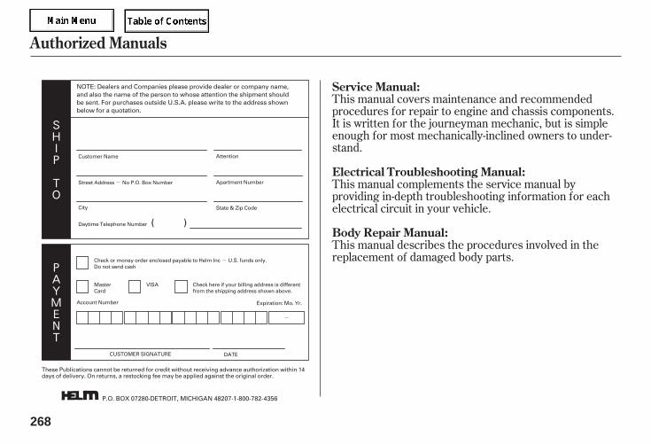
-
-
-
SHIP
TO
PAYMENT
This manual covers maintenance and recommendedprocedures for repair to engine and chassis components.It is written for the journeyman mechanic, but is simpleenough for most mechanically-inclined owners to under-stand.
This manual complements the service manual byproviding in-depth troubleshooting information for eachelectrical circuit in your vehicle.
This manual describes the procedures involved in thereplacement of damaged body parts.
Authorized Manuals
Service Manual:
Electrical Troubleshooting Manual:
Body Repair Manual:
268
NOTE: Dealers and Companies please provide dealer or company name,and also the name of the person to whose attention the shipment shouldbe sent. For purchases outside U.S.A. please write to the address shownbelow for a quotation.
P.O. BOX 07280·DETROIT, MICHIGAN 48207·1-800-782-4356
Customer Name Attention
Apartment Number
State & Zip CodeCity
Daytime Telephone Number
Check or money order enclosed payable to Helm Inc U.S. funds only.Do not send cash
MasterCard
VISA Check here if your billing address is differentfrom the shipping address shown above.
Account Number Expiration: Mo. Yr.
CUSTOMER SIGNATURE DATE
Street Address No P.O. Box Number
( )
These Publications cannot be returned for credit without receiving advance authorization within 14days of delivery. On returns, a restocking fee may be applied against the original order.
05/09/02 12:08:19 31SDR610 0271
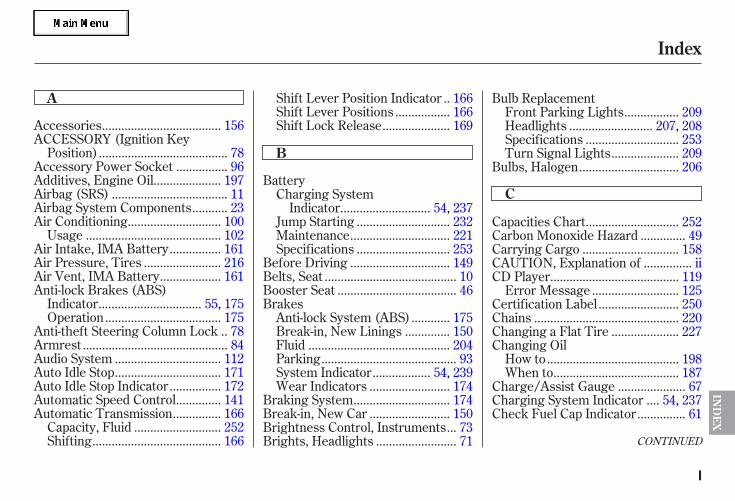
CONTINUED
....................................Accessories . 156ACCESSORY (Ignition Key
.......................................Position) . 78...............Accessory Power Socket . 96
....................Additives, Engine Oil . 197...................................Airbag (SRS) . 11
..........Airbag System Components . 23............................Air Conditioning . 100
.........................................Usage . 102...............Air Intake, IMA Battery . 161
.......................Air Pressure, Tires . 216..................Air Vent, IMA Battery . 161
Anti-lock Brakes (ABS)...............................Indicator . 55, 175
...................................Operation . 175.Anti-theft Steering Column Lock . 78
............................................Armrest . 84................................Audio System . 112................................Auto Idle Stop . 171
...............Auto Idle Stop Indicator . 172.............Automatic Speed Control . 141..............Automatic Transmission . 166
..........................Capacity, Fluid . 252.......................................Shifting . 166
.Shift Lever Position Indicator . 166................Shift Lever Positions . 166
....................Shift Lock Release . 169
BatteryCharging System
...........................Indicator . 54, 237............................Jump Starting . 232
..............................Maintenance . 221............................Specifications . 253
..............................Before Driving . 149........................................Belts, Seat . 10
....................................Booster Seat . 46Brakes
...........Anti-lock System (ABS) . 175.............Break-in, New Linings . 150
...........................................Fluid . 204.........................................Parking . 93
.................System Indicator . 54, 239........................Wear Indicators . 174
.............................Braking System . 174........................Break-in, New Car . 150
..Brightness Control, Instruments . 73........................Brights, Headlights . 71
Bulb Replacement................Front Parking Lights . 209
.........................Headlights . 207, 208............................Specifications . 253
....................Turn Signal Lights . 209..............................Bulbs, Halogen . 206
............................Capacities Chart . 252.............Carbon Monoxide Hazard . 49
.............................Carrying Cargo . 158..............CAUTION, Explanation of . ii
.......................................CD Player . 119..........................Error Message . 125........................Certification Label . 250
............................................Chains . 220....................Changing a Flat Tire . 227
Changing Oil........................................How to . 198......................................When to . 187
....................Charge/Assist Gauge . 67...Charging System Indicator . 54, 237
..............Check Fuel Cap Indicator . 61
Index
A
B
C
IND
EX
I
05/09/02 12:08:24 31SDR610 0272
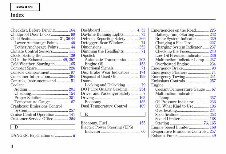
................DANGER, Explanation of . ii
...................................Dashboard . 4, 52................Daytime Running Lights . 73............Defects, Reporting Safety . 266
................Defogger, Rear Window . 74....................................Dimensions . 252
...............Dimming the Headlights . 71Dipstick
..........Automatic Transmission . 203..................................Engine Oil . 153
..........................Directional Signals . 71........Disc Brake Wear Indicators . 174
.....................Disposal of Used Oil . 199Doors
..............Locking and Unlocking . 79..........DOT Tire Quality Grading . 254
...........Driver and Passenger Safety . 7...........................................Driving . 163
....................................Economy . 155..........Dual Temperature Control . 109
............Checklist, Before Driving . 164..................Childproof Door Locks . 80
............................Child Seats . 31, 36-44...........Lower Anchorage Points . 40..........Tether Anchorage Points . 44
..............Climate Control Sensors . 111.........................Clock, Setting the . 139..................CO in the Exhaust . 49, 257
............Cold Weather, Starting in . 165..............................Compact Spare . 226
...................Console Compartment . 97
.................Consumer Information . 264.............Controls, Instruments and . 51
Coolant........................................Adding . 201
....................................Checking . 154.........................Proper Solution . 201
...................Temperature Gauge . 67Crankcase Emissions Control
........................................System . 257............Cruise Control Operation . 141.............Customer Service Office . 264
..............................Economy, Fuel . 155Electric Power Steering (EPS)
.......................................Indicator . 60
............Emergencies on the Road . 225.............Battery, Jump Starting . 232...........Brake System Indicator . 239
................Changing a Flat Tire . 227.....Charging System Indicator . 237
..................Checking the Fuses . 243.....Low Oil Pressure Indicator . 236...Malfunction Indicator Lamp . 237
..................Overheated Engine . 234...........................Emergency Brake . 93
......................Emergency Flashers . 74......................Emergency Towing . 241.......................Emissions Controls . 257
Engine....Coolant Temperature Gauge . 67
Malfunction Indicator......................................Lamp . 237
..............Oil Pressure Indicator . 236
..............Oil, What Kind to Use . 196...............................Overheating . 234
............................Specifications . 252
............................Speed Limiter . 168................................Starting . 76, 165
...................Engine Speed Limiter . 168.Evaporative Emissions Controls . 257
...............................Exhaust Fumes . 49
Index
D
E
II
05/09/02 12:08:29 31SDR610 0273
CONTINUED
Expectant Mothers, Use of Seat........................................Belts by . 18
...................................Fan, Interior . 102...........................................Features . 99
....................Filling the Fuel Tank . 151........................................Filter, Oil . 198
.............Flashers, Hazard Warning . 74......................Flat Tire, Changing . 227
.......................................Floor Mat . 212Fluids
..........Automatic Transmission . 203..........................................Brake . 204
..................Windshield Washer . 200..........................Four-way Flashers . 74
.................................................Fuel . 150...............................Cap Message . 61
.....................Economy Indicator . 61......................Fill Door and Cap . 151
...........................................Gauge . 68................Octane Requirement . 150
........................Tank, Filling the . 151.....................Fuses, Checking the . 243
...............Gas Mileage, Improving . 155.........................................Gasoline . 150...........................................Gauge . 68
................Octane Requirement . 150........................Tank, Filling the . 151
................Gas Station Procedures . 151Gauges
...Engine Coolant Temperature . 67...............................................Fuel . 68
Gearshift Lever Positions..........Automatic Transmission . 166
........................................Glove Box . 98
.............Halogen Headlight Bulbs . 206..............Hazard Warning Flashers . 74
........................................Headlights . 71........................................Aiming . 206
..............Automatic Lighting Off . 72............Daytime Running Lights . 73............Low Beams, Turning on . 71
.........................Reminder Chime . 71........Replacing Halogen Bulbs . 206
...................................Turning on . 71..............................Head Restraints . 87
.....................Heating and Cooling . 100HomeLink Universal
................................Transceiver . 144..Hood, Opening and Closing the . 152
...Identification Number, Vehicle . 250Ignition
..............................................Keys . 76...........................................Switch . 78
............Timing Control System . 258....................IMA System Indicator . 60
........................Immobilizer System . 77.........Important Safety Precautions . 8
.........Indicators, Instrument Panel . 53...............................Infant Restraint . 36
......................................Infant Seats . 36..........Tether Anchorage Points . 44
...................Inflation, Proper Tire . 215...................................Inside Mirror . 88
.............................Inspection, Tire . 217
Index
F
G
H
I
IND
EX
III
05/09/02 12:08:35 31SDR610 0274
....................Installing a Child Seat . 39..........Tether Anchorage Points . 44
.............................Using LATCH . 40............................Instrument Panel . 53
........Instrument Panel Brightness . 73........................................Introduction . i
.................Jacking up the Vehicle . 227.......................................Jack, Tire . 227
................................Jump Starting . 232
..................................................Keys . 76
.......................Label, Certification . 250.................Lane Change, Signaling . 71
........................Lap/Shoulder Belts . 20Lights
....................Bulb Replacement . 206.......................................Indicator . 57
.......................................Parking . 209
..................................Turn Signal . 57....................................Load Limits . 159
......LOCK (Ignition Key Position) . 78Locks
.......Anti-theft Steering Column . 78............................Fuel Fill Door . 151
....................................Glove Box . 98....................Lockout Prevention . 79
.................................Power Door . 79...........................................Trunk . 83
........................Low Coolant Level . 154...Lower Gear, Downshifting to a . 166
...Low Oil Pressure Indicator . 54, 236...Lubricant Specifications Chart . 252
.........................................Luggage . 158
..................................Maintenance . 185...Owner Maintenance Checks . 191
........................................Record . 193.........................Minder Indicator . 59
..........................................Safety . 186................................Minder . 187-192
.Malfunction Indicator Lamp . 54, 237...............................Meters, Gauges . 62
..........................Mirrors, Adjusting . 88.................................Modifications . 157
.........................................Moonroof . 92
...................Neutral Gear Position . 167..................New Vehicle Break-in . 150
...................NOTICE, Explanation of . i...............Numbers, Identification . 250
...Octane Requirement, Gasoline . 150.........................................Odometer . 63
Oil........................Change, How to . 198...............Change, When to . 187-192......................Checking Engine . 153..............Pressure Indicator . 54, 236
Selecting Proper Viscosity......................................Chart . 196
...........ON (Ignition Key Position) . 78..............................Outside Mirrors . 88
.....................Outside Temperature . 63....................Overheating, Engine . 234
Index
J
K
LM
N
O
IV
05/09/02 12:08:43 31SDR610 0275
CONTINUED
..............Panel Brightness Control . 73........................Park Gear Position . 167
.................................Parking Brake . 93
.................................Parking Lights . 71Parking Over Things that
....................................Burn . 173, 259..................................Parking Tips . 173
.............................PGM-FI System . 258....................Power Mirror Heaters . 89
.........Pregnancy, Using Seat Belts . 18
.........Protecting Adults and Teens . 13...Additional Safety Precautions . 19
.....Advice for Pregnant Women . 18........................Protecting Children . 31
Protecting Infants and Small.......................................Children . 36
...........Protecting Larger Children . 45.....................Using Booster Seat . 46
...................Radiator Overheating . 234
Radio/CD Sound........................................System . 112
Rear Lights, Bulb......................Replacement . 210, 211
............................Rear View Mirror . 88.................Rear Window Defogger . 74.........Reclining the Seat Backs . 86, 87
.............................Reminder Lights . 53.......................Remote Transmitter . 80
Replacement Information................Engine Oil and Filter . 198
..........................................Fuses . 243................................Light Bulbs . 206
................................Minder . 187-192...........................................Tires . 218
.............................Wiper Blades . 213Replacing Seat Belts After a
............................................Crash . 21.................Reserve Tank, Coolant . 201
...............................Restraint, Child . 31..................Reverse Gear Position . 167
................................Rotation, Tire . 218
......................................Safety Belts . 10
............Safety Defects, Reporting . 266.................................Safety Features . 9
.........................................Airbags . 11.....................................Seat Belts . 10
.............Safety Labels, Location of . 50...............................Safety Messages . ii
................................Satellite Radio . 131.........................................Seat Belts . 10
...............Additional Information . 20Automatic Seat Belt
...............................Tensioners . 21......................Lap/Shoulder Belt . 20
................................Maintenance . 21Reminder Indicator and
................................Beeper . 20, 54...................System Components . 20
...............Use During Pregnancy . 18...Wearing a Lap/Shoulder Belt . 20
........................Seats, Adjusting the . 85............................Security System . 140
.....................Selecting a Child Seat . 38.........................Select/Reset Knob . 73
...............................Serial Number . 250....................Service Intervals . 187-192
....Owner’s Maintenance Checks . 191
Index
P
R S
IND
EX
V
05/09/02 12:08:49 31SDR610 0276
.............................Service Manual . 267...........Service Station Procedure . 151
..........................Setting the Clock . 139.....Shift Lever Position Indicator . 166
........................Shift Lock Release . 169..............................Side Airbags . 11, 26
...How Your Side Airbags Work . 26How the Side Airbag Off
......................Indicator Works . 28
................Side Curtain Airbags . 11, 27How Your Side Curtain
..........................Airbags Work . 27...............................Signaling Turns . 71
.....................................Snow Tires . 219................................Sound System . 112
Spare Tire......................................Inflating . 226
............................Specifications . 253....................Specifications Charts . 252
................................Speed Control . 141
................................Speed Limiter . 168..........SRS, Additional Information . 23
...Additional Safety Precautions . 30.............................Airbag Service . 29
How Your SRS Indicator.......................................Works . 28
How Your Front Airbags.......................................Works . 24
How Your Side Airbags.......................................Works . 26
........................SRS Components . 23.............................SRS Indicator . 28, 55
....START (Ignition Key Position) . 78.......................Starting the Engine . 165
................With a Dead Battery . 232........Steam Coming from Engine . 234
Steering Wheel..................................Adjustment . 75
.............Anti-theft Column Lock . 78...................Stereo Sound System . 112
..........................................Sun Visor . 94..........................Sunglasses Holder . 98
Supplemental Restraint................................System . 11, 23......................................Servicing . 29
.........................SRS Indicator . 28, 55...................System Components . 23
..................................Synthetic Oil . 197
.Taking Care of the Unexpected . 225
Technical Descriptions......DOT Tire Quality Grading . 254.....Emissions Control Systems . 257
Three Way Catalytic...............................Converter . 259
.......................Temperature Gauge . 67..............Tether Anchorage Points . 44
..Three Way Catalytic Converter . 259..........................Time, Setting the . 139
....................................Timing Belt . 205
....................................Tire Chains . 220.........Tire, How to Change a Flat . 227
.................................Tire Labeling . 256...............................................Tires . 215
..............................Air Pressure . 216.........................Checking Wear . 217..........................Compact Spare . 226
......DOT Tire Quality Grading . 254......................................Inflation . 215
..................................Inspection . 217...................................Replacing . 218
......................................Rotating . 218...........................................Snow . 219
............................Specifications . 253...................Tools, Tire Changing . 227
Index
T
VI
05/09/02 12:08:53 31SDR610 0277
Unexpected, Taking Care..........................................of the . 225
....Uniform Tire Quality Grading . 254........................Unleaded Gasoline . 150
.....................Upholstery Cleaning . 212.......Used Oil, How to Dispose of . 199
.............WARNING, Explanation of . ii.........Warning Labels, Location of . 50
....................Warranty Coverages . 265Washer, Windshield
........Checking the Fluid Level . 200.....................................Operation . 70
Wheels...............Adjusting the Steering . 75
............Alignment and Balance . 217..........................Compact Spare . 226
......................................Wrench . 227Windows
..................Operating the Power . 89...........................Rear, Defogger . 74
Windshield.......................................Cleaning . 70.......................................Washers . 70
Wipers, Windshield.......................Changing Blades . 213
.....................................Operation . 70....................................Worn Tires . 217
.....Wrecker, Emergency Towing . 241
Towing.....................................A Trailer . 179
................Emergency Wrecker . 241Transmission
Checking Fluid Level,..............................Automatic . 203
...........................Fluid Selection . 203..............Identification Number . 250.............Shifting the Automatic . 166
.....................................Treadwear . 217
.......................................Trip Meter . 64................................................Trunk . 83
....................Emergency Opener . 84.................................Opening the . 83
.............Open Monitor Indicator . 56....................................Turn Signals . 71
..................................Vanity Mirror . 94.................Vehicle Capacity Load . 159
......................Vehicle Dimensions . 252....Vehicle Identification Number . 250
Vehicle Stability Assist (VSA)....................................System . 177
............Activation Indicator . 56, 177..................................Off Switch . 178
.................System Indicator . 56, 177.............................Vehicle Storage . 222
.................................................VIN . 250..................................Viscosity, Oil . 196
...........Voice Control System . 102, 113
Index
U
V
W
IND
EX
VII
05/09/02 12:08:59 31SDR610 0278
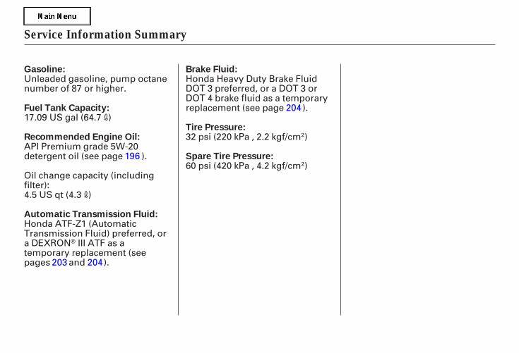
Service Information Summary
Gasoline:
Fuel Tank Capacity:
Recommended Engine Oil:
Brake Fluid:
Tire Pressure:
Automatic Transmission Fluid:
Spare Tire Pressure:
17.09 US gal (64.7 )
Unleaded gasoline, pump octanenumber of 87 or higher.
API Premium grade 5W-20detergent oil (see page ).
Honda Heavy Duty Brake FluidDOT 3 preferred, or a DOT 3 orDOT 4 brake fluid as a temporaryreplacement (see page ).
Oil change capacity (includingfilter):4.5 US qt (4.3 )
Honda ATF-Z1 (AutomaticTransmission Fluid) preferred, ora DEXRON III ATF as atemporary replacement (seepages and ).
32 psi (220 kPa , 2.2 kgf/cm )
60 psi (420 kPa , 4.2 kgf/cm )196
203 204
204
05/09/02 12:09:12 31SDR610 0281