Embed Size (px)
Citation preview

RF BASICS
Low Power WirelessTexas Instruments

Agenda
• Defintions
• RF Systems
• Modulation Formats
• System Range
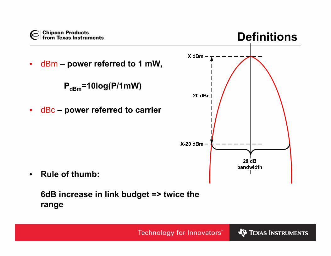
Definitions
• dBm – power referred to 1 mW,
PdBm=10log(P/1mW)
• dBc – power referred to carrier
• Rule of thumb:
6dB increase in link budget => twice the range

Definitions (2)
• PER Packet Error Rate, % of packets not successfully received
• Sensitivity Lowest input power with acceptable link quality, typically 1% PER
• Deviation/separation Frequency offset between a logic ‘0’ and ‘1’ using FSK modulation
• Blocking/selectivity How well a chip works in an environment with interference

Agenda
• Defintions
• RF Systems
• Modulation Formats
• System Range
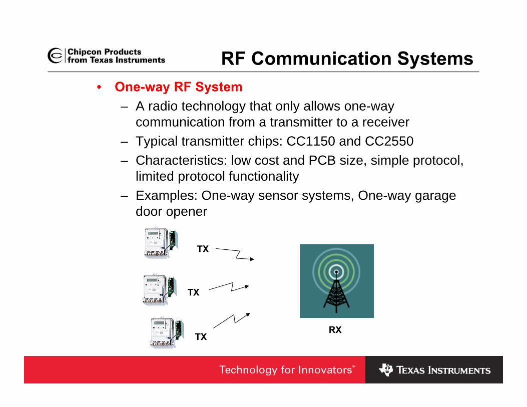
RF Communication Systems• One-way RF System
– A radio technology that only allows one-waycommunication from a transmitter to a receiver
– Typical transmitter chips: CC1150 and CC2550– Characteristics: low cost and PCB size, simple protocol,
limited protocol functionality– Examples: One-way sensor systems, One-way garage
door opener
TX
TX
TXRX
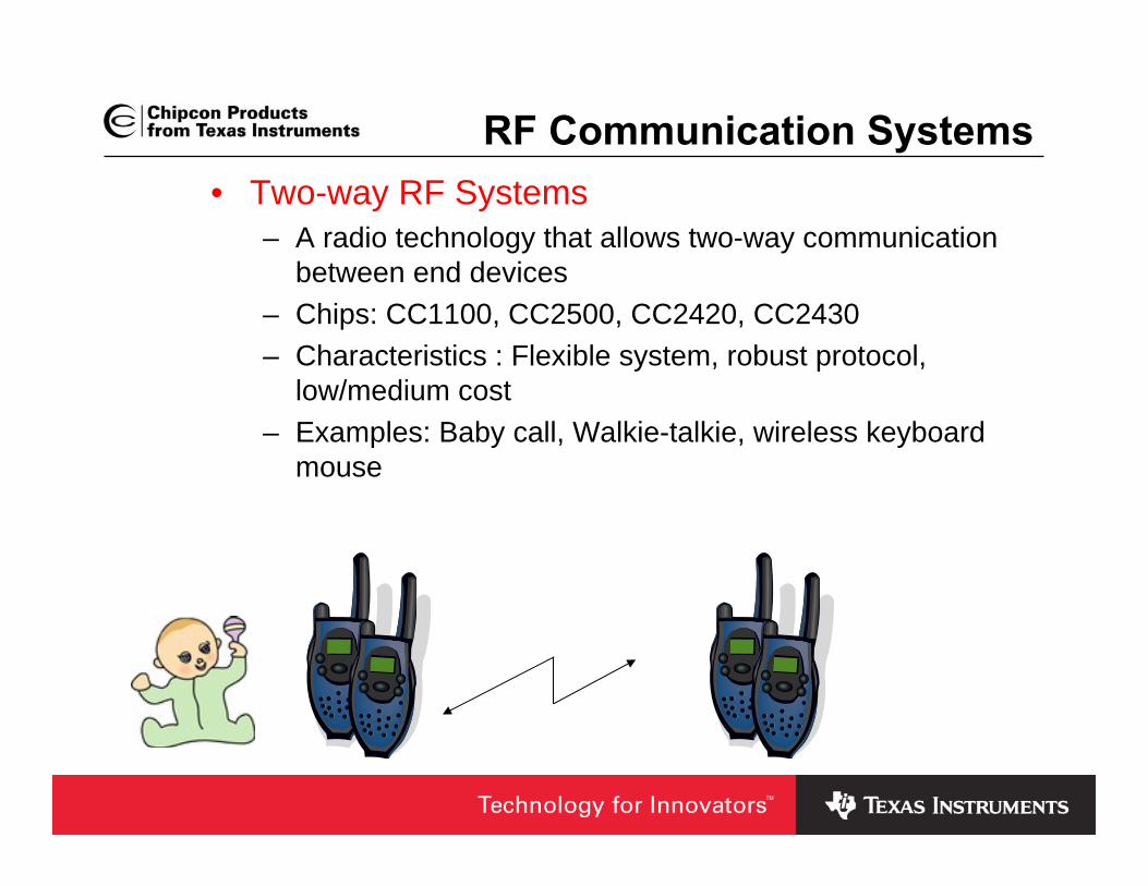
RF Communication Systems• Two-way RF Systems
– A radio technology that allows two-way communicationbetween end devices
– Chips: CC1100, CC2500, CC2420, CC2430– Characteristics : Flexible system, robust protocol,
low/medium cost– Examples: Baby call, Walkie-talkie, wireless keyboard
mouse

Basic Building Blocks of an RF System• RF-IC
– Transmitter– Transceiver– System-on-Chip (SoC);
typically transceiver withintegrated microcontroller
• Crystal– Reference frequency for the
LO and the carrier frequency
• Balun– Balanced to unbalanced– Converts a differential
signal to a single-ended signal or vice versa
• Matching• Filter
– Used if needed to pass regulatory requirements / improve selectivity
• Antenna
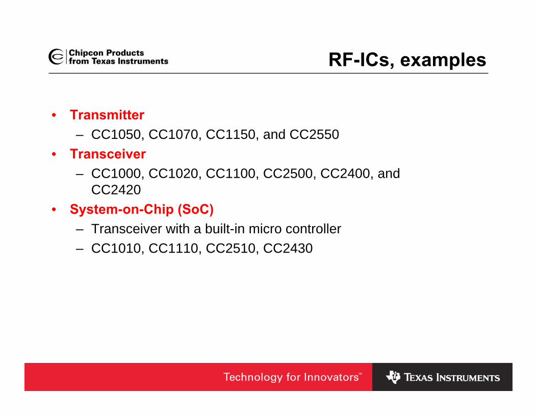
RF-ICs, examples
• Transmitter– CC1050, CC1070, CC1150, and CC2550
• Transceiver – CC1000, CC1020, CC1100, CC2500, CC2400, and
CC2420• System-on-Chip (SoC)
– Transceiver with a built-in micro controller– CC1010, CC1110, CC2510, CC2430

Agenda
• Defintions
• RF Systems
• Modulation Formats
• System Range

Modulation and Demodulation
digitalmodulation
digitaldata analog
modulation
radiocarrier
analogbasebandsignal
101101001 Radio Transmitter
synchronizationdecision
digitaldataanalog
demodulation
radiocarrier
analogbasebandsignal
101101001 Radio Receiver
Source: Lili Qiu
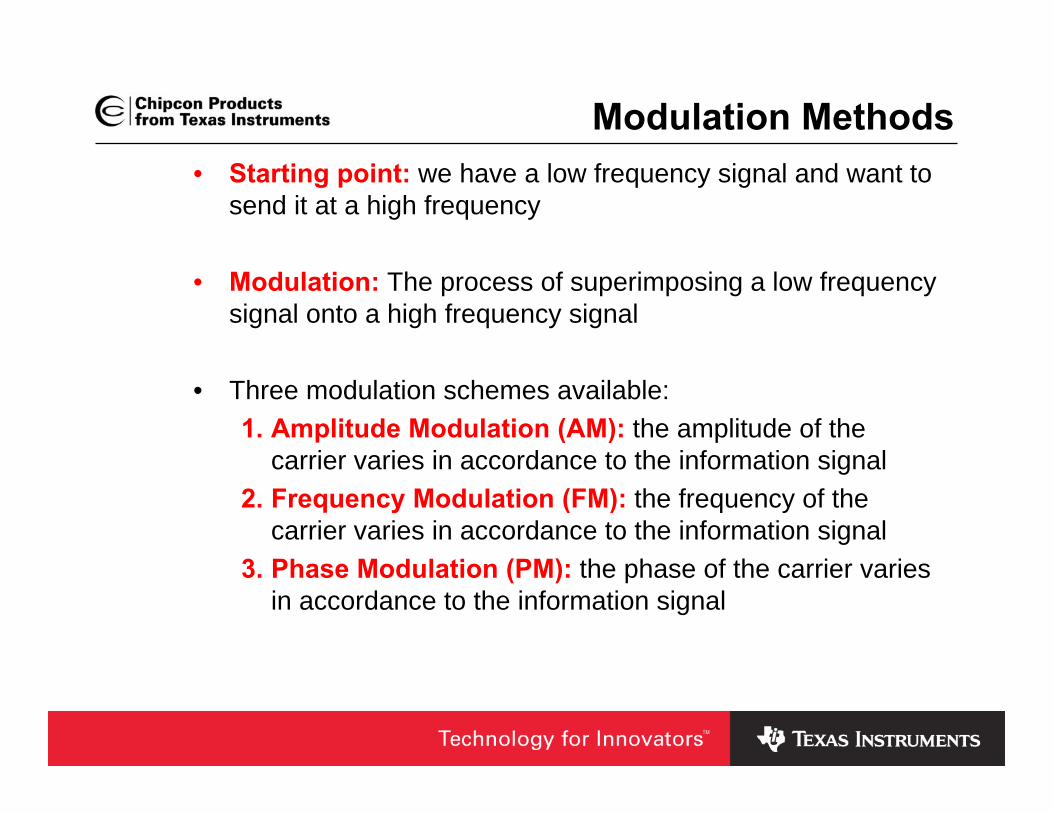
Modulation Methods• Starting point: we have a low frequency signal and want to
send it at a high frequency
• Modulation: The process of superimposing a low frequencysignal onto a high frequency signal
• Three modulation schemes available:1. Amplitude Modulation (AM): the amplitude of the
carrier varies in accordance to the information signal2. Frequency Modulation (FM): the frequency of the
carrier varies in accordance to the information signal3. Phase Modulation (PM): the phase of the carrier varies
in accordance to the information signal
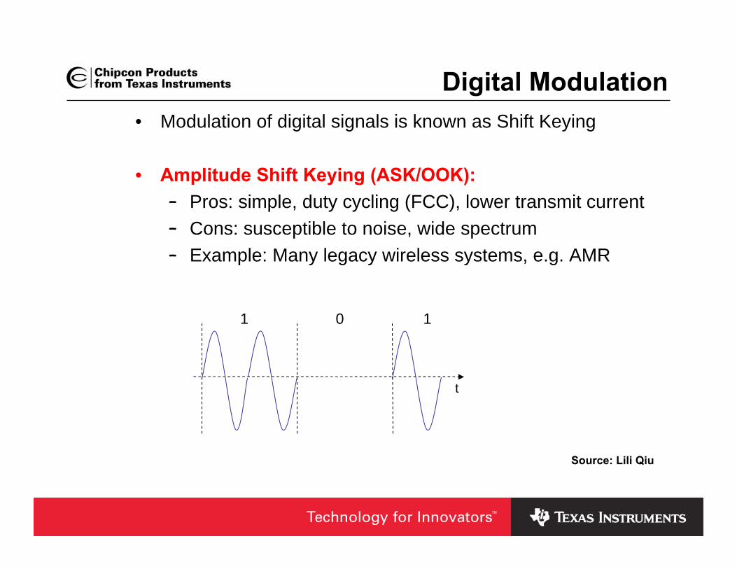
Digital Modulation• Modulation of digital signals is known as Shift Keying
• Amplitude Shift Keying (ASK/OOK):– Pros: simple, duty cycling (FCC), lower transmit current– Cons: susceptible to noise, wide spectrum– Example: Many legacy wireless systems, e.g. AMR
1 0 1
t
Source: Lili Qiu

Digital Modulation• Frequency Shift Keying (FSK):
– Pros: less susceptible to noise– Cons: theoretically requires larger bandwidth/bit than
ASK– Popular in modern systems– Gaussian FSK (GFSK) has better spectral density than
2-FSK modulation, i.e. more bandwidth efficient
1 0 1
t
1 0 1
Source: Lili Qiu

Digital Modulation
• Phase Shift Keying (PSK):– Pros:
• Less susceptible to noise• Bandwidth efficient
– Cons:• Require synchronization in frequency and phase
complicates receivers and transmitter– Example: IEEE 802.15.4 / ZigBee
t
1 10
Source: Lili Qiu
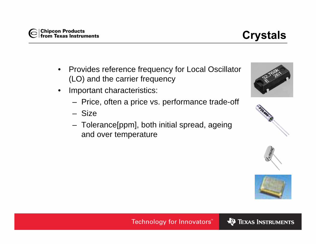
Crystals
• Provides reference frequency for Local Oscillator (LO) and the carrier frequency
• Important characteristics:– Price, often a price vs. performance trade-off– Size– Tolerance[ppm], both initial spread, ageing
and over temperature
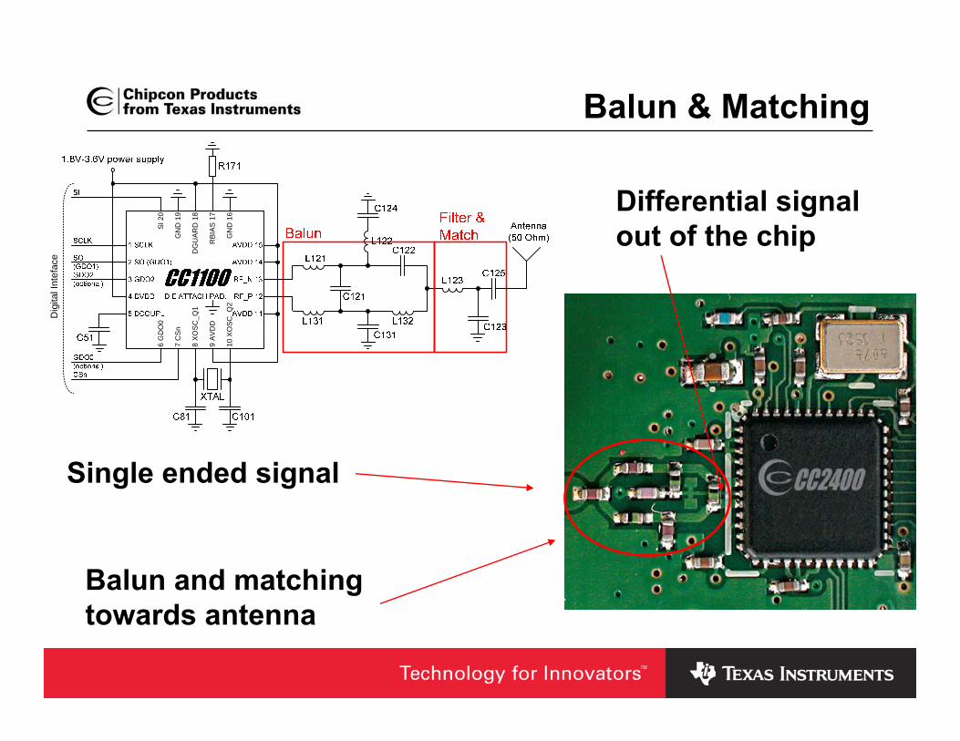
Balun & Matching
Balun and matching towards antenna
Differential signal out of the chip
Single ended signal
Dig
ital I
ntef
ace
6 G
DO
0
7 C
Sn
8 XO
SC
_Q1
9 AV
DD
10 X
OSC
_Q2
SI 2
0
GN
D 1
9
DG
UA
RD
18
RBI
AS
17
GN
D 1
6

Antennas, commonly used• PCB antennas
– Little extra cost (PCB)– Size demanding at low frequencies– Good performance possible– Complicated to make good designs
• Whip antennas– Expensive (unless piece of wire)– Good performance– Hard to fit in may applications
• Chip antennas– Expensive– OK performance– Small size

Extending the Range of an RF System1. Increase the Output power
– Add an external Power Amplifier (PA)
2. Increase the sensitivity– Add an external Low
Noise Amplifier (LNA)
3. Increase both output power and sensitivity– Add PA and LNA
4. Use high gain antennas– Regulatory
requirements need to be followed
RF-IC Balun & Match
2/1 Switch2/1 Switch
LNA
PA Filter
Crystal
Antenna(50Ω)

Agenda
• Defintions
• RF Systems
• Modulation Formats
• System Range

Radio Range – Important Factors
• Antenna • Sensitivity• Output power• Radio pollution (selectivity, blocking, IP3)• Environment (Line of sight, obstructions,
reflections, multipath fading)
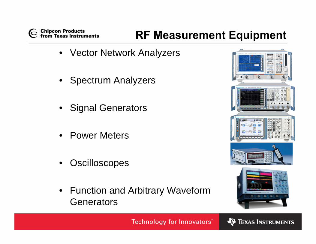
RF Measurement Equipment• Vector Network Analyzers
• Spectrum Analyzers
• Signal Generators
• Power Meters
• Oscilloscopes
• Function and Arbitrary WaveformGenerators
Questions?

Worldwide License-Free Frequency Allocations
Low Power WirelessTexas Instruments

Agenda
• The ISM/SRD License-Free Frequency Bands– Global 2.4 GHz band and regional Sub-1GHz bands
• The global 2.4 GHz ISM band– USA– Europe– Japan/Korea
• Sub-1GHz ISM bands– USA– Europe– Japan/Korea
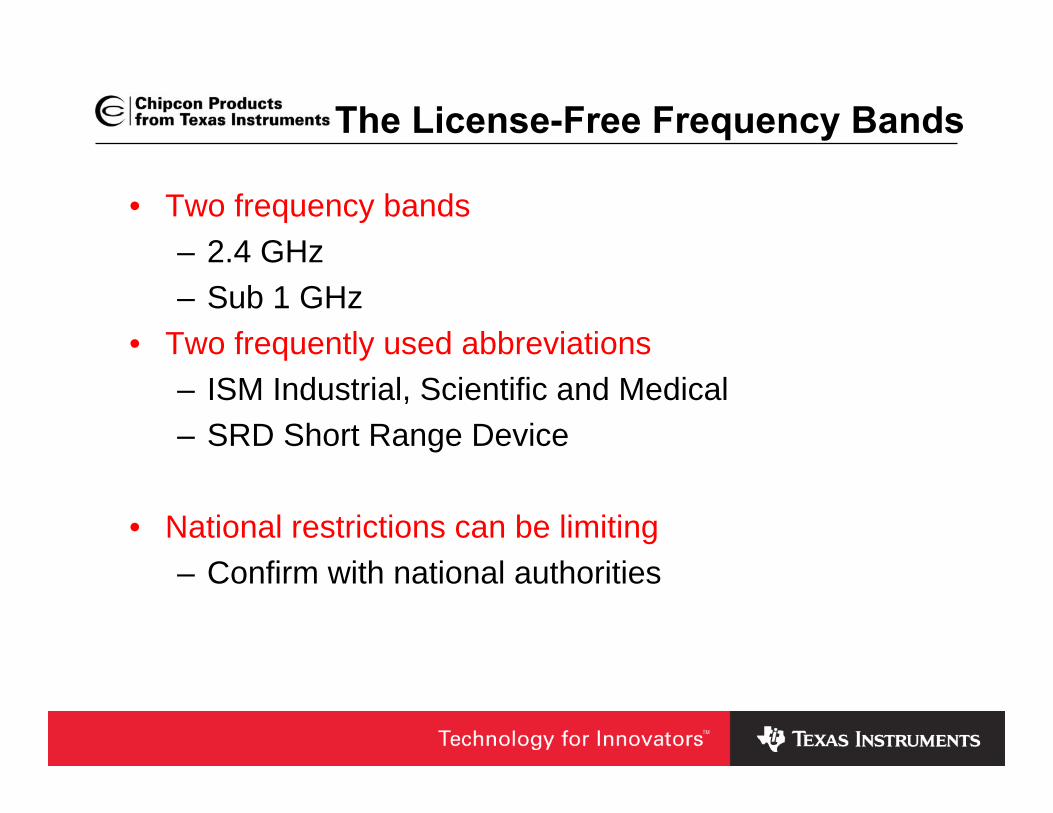
The License-Free Frequency Bands
• Two frequency bands– 2.4 GHz – Sub 1 GHz
• Two frequently used abbreviations– ISM Industrial, Scientific and Medical– SRD Short Range Device
• National restrictions can be limiting– Confirm with national authorities
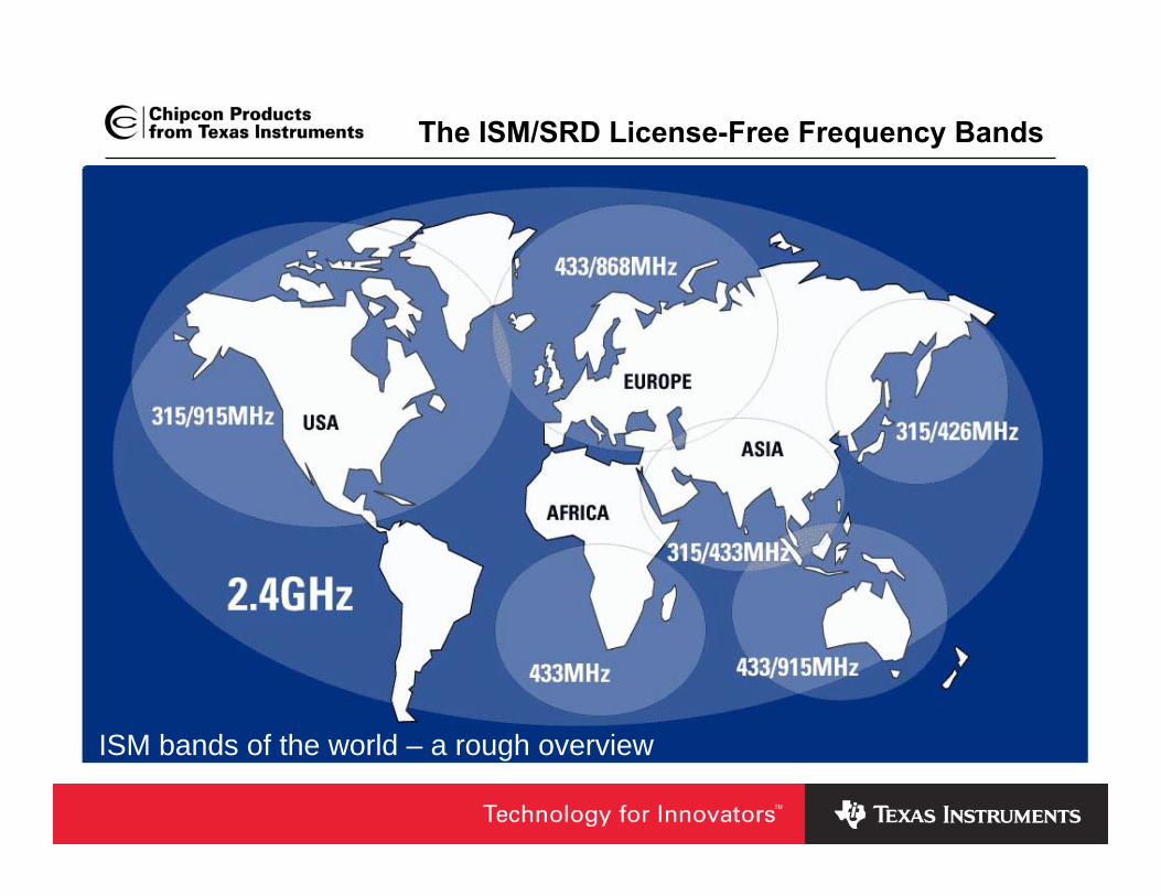
The ISM/SRD License-Free Frequency Bands
ISM bands of the world – a rough overview
Agenda
• The ISM/SRD License-Free Frequency Bands– Global 2.4 GHz band and regional Sub-1 GHz bands
• The global 2.4 GHz ISM band– USA– Europe– Japan/Korea
• Sub 1GHz ISM bands– USA– Europe– Japan/Korea

The global 2.4 GHz ISM band• The 2400–2483.5 MHz band
– Pros• Same solution world wide• Large bandwidth• 100% duty cycle allowed
– Cons• Shorter range • Crowded

The global 2.4 GHz ISM band
• 2.4 GHz in USA (Canada)
– FCC CFR 47, Part 15.• FCC certification required
– Sharing of the bandwidth: ”if you do not occupy one channelall the time, we will allow you to transmit with higher output power”
• FCC CFR 47 part 15.247 cover wideband modulation– up to 1W/30 dBm output power with FHSS or DSSS
• FCC CFR 47 part 15.249 cover single channel systems– ~0.75mW/-1.25 dBm output power

The global 2.4 GHz ISM band• 2.4 GHz in Europe
– CEPT ERC/REC 70-03, ETSI EN 300 328 and EN 300 440• ”Self certification” is possible
– Equipment classes• EN 300 328 cover wideband modulation systems
– Output power of 100mW with FHSS and DSSS– Spectral Power Density limitations
• EN 300 440 cover non-specific SRDs– Output power of 10mW
– Similar as FCC: ”By spreading the transmitted power you areallowed a higher output power”

The global 2.4 GHz ISM band
• 2.4 GHz in Japan (Korea)
– ARIB STD T-66 Japan• Certification required
• Modulation is DSSS, FHSS or other digital modulation
• Output power of 10mW in a 1MHz bandwidth
Agenda
• The ISM/SRD License-Free Frequency Bands– Global 2.4 GHz band and regional Sub-1 GHz bands
• The global 2.4 GHz ISM band– Regional Differences
• Sub 1-GHz ISM bands– USA– Europe– Japan/Korea

Sub 1-GHz ISM bands
• Regional limitations
– Pros• Better range• Less crowded
– Cons• Custom solutions• Limitations in “performance”• Duty cycle restrictions

Sub-1GHz ISM bands• Sub-1GHz ISM bands in USA (Canada)
– Covered by FCC CFR 47, part 15
– 902 - 928 MHz• FCC CFR 47 part 15.247 cover wideband modulation
– Up to 1W/30 dBm output power with FHSS or DSSS– CC1100 250kbps/FSK/10 dBm is OK, DN006
• FCC CFR 47 part 15.249 cover single channel systems– ~0.75mW/-1.25 dBm output power
– FCC part 15.231 Periodic operation above 70 MHz• Restricted to control signals: alarm, door openers,
remote switches• Operation not allowed in restricted bands, 15.205.

Sub-1GHz ISM bands• Sub-1GHz ISM bands in Europe
– 433.05-434.79 MHz and 863-870 MHz covered by CEPT ERC/REC 70-03, ETSI EN 300 220
• Old version of EN 300 220 is valid until 31.12.2007
• Narrow channels (25kHz channel spacing)
• LBT (Listen Before Talk) regulations

Sub-1GHz ISM bands
• Sub 1GHz ISM bands in Japan (Korea)
– Limited availability
– ARIB STD-T67 covers 426-430 MHz band
– 12.5 and 25kHz channelspacing requirements
Thank you for your attention.
Questions?
IMPORTANT NOTICE
Texas Instruments Incorporated and its subsidiaries (TI) reserve the right to make corrections, modifications, enhancements,improvements, and other changes to its products and services at any time and to discontinue any product or service without notice.Customers should obtain the latest relevant information before placing orders and should verify that such information is current andcomplete. All products are sold subject to TI’s terms and conditions of sale supplied at the time of order acknowledgment.
TI warrants performance of its hardware products to the specifications applicable at the time of sale in accordance with TI’sstandard warranty. Testing and other quality control techniques are used to the extent TI deems necessary to support thiswarranty. Except where mandated by government requirements, testing of all parameters of each product is not necessarilyperformed.
TI assumes no liability for applications assistance or customer product design. Customers are responsible for their products andapplications using TI components. To minimize the risks associated with customer products and applications, customers shouldprovide adequate design and operating safeguards.
TI does not warrant or represent that any license, either express or implied, is granted under any TI patent right, copyright, maskwork right, or other TI intellectual property right relating to any combination, machine, or process in which TI products or servicesare used. Information published by TI regarding third-party products or services does not constitute a license from TI to use suchproducts or services or a warranty or endorsement thereof. Use of such information may require a license from a third party underthe patents or other intellectual property of the third party, or a license from TI under the patents or other intellectual property of TI.
Reproduction of TI information in TI data books or data sheets is permissible only if reproduction is without alteration and isaccompanied by all associated warranties, conditions, limitations, and notices. Reproduction of this information with alteration is anunfair and deceptive business practice. TI is not responsible or liable for such altered documentation. Information of third partiesmay be subject to additional restrictions.
Resale of TI products or services with statements different from or beyond the parameters stated by TI for that product or servicevoids all express and any implied warranties for the associated TI product or service and is an unfair and deceptive businesspractice. TI is not responsible or liable for any such statements.
TI products are not authorized for use in safety-critical applications (such as life support) where a failure of the TI product wouldreasonably be expected to cause severe personal injury or death, unless officers of the parties have executed an agreementspecifically governing such use. Buyers represent that they have all necessary expertise in the safety and regulatory ramificationsof their applications, and acknowledge and agree that they are solely responsible for all legal, regulatory and safety-relatedrequirements concerning their products and any use of TI products in such safety-critical applications, notwithstanding anyapplications-related information or support that may be provided by TI. Further, Buyers must fully indemnify TI and itsrepresentatives against any damages arising out of the use of TI products in such safety-critical applications.
TI products are neither designed nor intended for use in military/aerospace applications or environments unless the TI products arespecifically designated by TI as military-grade or "enhanced plastic." Only products designated by TI as military-grade meet militaryspecifications. Buyers acknowledge and agree that any such use of TI products which TI has not designated as military-grade issolely at the Buyer's risk, and that they are solely responsible for compliance with all legal and regulatory requirements inconnection with such use.
TI products are neither designed nor intended for use in automotive applications or environments unless the specific TI productsare designated by TI as compliant with ISO/TS 16949 requirements. Buyers acknowledge and agree that, if they use anynon-designated products in automotive applications, TI will not be responsible for any failure to meet such requirements.
Following are URLs where you can obtain information on other Texas Instruments products and application solutions:
Products Applications
Amplifiers amplifier.ti.com Audio www.ti.com/audio
Data Converters dataconverter.ti.com Automotive www.ti.com/automotive
DSP dsp.ti.com Broadband www.ti.com/broadband
Interface interface.ti.com Digital Control www.ti.com/digitalcontrol
Logic logic.ti.com Military www.ti.com/military
Power Mgmt power.ti.com Optical Networking www.ti.com/opticalnetwork
Microcontrollers microcontroller.ti.com Security www.ti.com/security
RFID www.ti-rfid.com Telephony www.ti.com/telephony
Low Power www.ti.com/lpw Video & Imaging www.ti.com/videoWireless
Wireless www.ti.com/wireless
Mailing Address: Texas Instruments, Post Office Box 655303, Dallas, Texas 75265Copyright © 2007, Texas Instruments Incorporated