Embed Size (px)
Citation preview

[1]
Project Number: XIH‐0809
2008-2009 WPI
802.11n Wireless Communication System Simulation Using Matlab
and Implementation on FPGA
A Major Qualifying Project Submitted to the faculty of
Worcester Polytechnic Institute in partial fulfillment of requirement for the
Degree of Bachelor of Science
Submitted By: ___________________________ Bach Duy Vo Approved: ___________________________ Professor Xinming Huang, Advisor
Date: April 30th, 2009

[2]
Table of Contents:
Abstract/Executive Summary .................................................................................................. 5
Chapter 1: Overview of the MQP Project ................................................................................. 6
1.1 Objective ....................................................................................................................... 6 1.2 Technical Approach ...................................................................................................... 7
Chapter 2: Background and Motivations .................................................................................. 9
2.1 Introduction to WLAN .................................................................................................. 9 2.2 802.11 standards ........................................................................................................ 10 2.3 802.11n ....................................................................................................................... 13 2.4 Introduction to MIMO‐OFDM systems ....................................................................... 15
Chapter 3: System Design and Matlab Simulation ................................................................. 23
3.1 Convolution Encoder .................................................................................................. 24 3.2 Interleaver and Deinterleaver .................................................................................... 25 3.3 Quadrature Amplitude Modulation .......................................................................... 26 3.4 Alamouti Encoder and Decoder ................................................................................. 27 3.5 Inverse and Forward Fast Fourier Transform ............................................................. 29 3.6 Viterbi decoder ........................................................................................................... 32 3.7 System Simulation and BER Result ............................................................................. 33
Chapter 4 HDL Design and Simulation .................................................................................... 35
4.1 Random data generator ............................................................................................. 35 4.2 Convolution Encoder .................................................................................................. 37 4.3 Interleaver and Deinterleaver .................................................................................... 39 4.4 16 QAM and D‐QAM ................................................................................................... 43 4.5 Alamouti Scheme ........................................................................................................ 46 4.6 Fast Fourier Transform ............................................................................................... 51 4.7 Viterbi ......................................................................................................................... 56 4.8 System Simulation Result ........................................................................................... 57
Chapter 5: Conclusion and Recommendations ....................................................................... 60
Bibliography .......................................................................................................................... 62
Appendix ............................................................................................................................... 63

[3]
List of Figures:
Figure 1: The flow of technical approach ...................................................................................................... 7 Figure 2: Block diagram for 802.11 transmitter .......................................................................................... 14 Figure 3: FDM [2] ........................................................................................................................................ 15 Figure 4: OFDM [2] ...................................................................................................................................... 16 Figure 5: OFDM modulator [6] .................................................................................................................... 17 Figure 6: Fast Fourier Transform [5] ........................................................................................................... 18 Figure 7: Fading path .................................................................................................................................. 18 Figure 8: MIMO one transmitter, two receivers [7] ................................................................................... 20 Figure 9: MIMO two transmitters, one receiver [7] ................................................................................... 21 Figure 10: 2x2 MIMO [7] ............................................................................................................................. 22 Figure 11: Wireless Communication System Block Diagram ...................................................................... 23 Figure 12: Example of Convolution Encoder constraint of 7 ...................................................................... 24 Figure 13: 16‐QAM mapping scheme ......................................................................................................... 26 Figure 14: BER result ................................................................................................................................... 33 Figure 15: LFSR ............................................................................................................................................ 36 Figure 16: Random number generator ....................................................................................................... 36 Figure 17: Convolution Encoder set up ....................................................................................................... 38 Figure 18: Convolution Simulation Result ................................................................................................... 39 Figure 19: Interleaver Block ........................................................................................................................ 40 Figure 20: Interleaver Simulation result ..................................................................................................... 41 Figure 21: Deinterleaver Block .................................................................................................................... 42 Figure 22: Simulation input to Deinterleaver ............................................................................................. 42 Figure 23: Deinterleaver Simulation Result ................................................................................................ 42 Figure 24: QAM block .................................................................................................................................. 44 Figure 25: QAM simulation Result .............................................................................................................. 44 Figure 26: D‐QAM block .............................................................................................................................. 45 Figure 27: D‐QAM Simulation Result .......................................................................................................... 45 Figure 28: Alamouti Encoder Block ............................................................................................................. 47 Figure 29: Alamouti Encoder Simulation Result ......................................................................................... 47 Figure 30: Alamouti Decoder ...................................................................................................................... 48 Figure 31: Choosing Scheme for Alamouti Decoder ................................................................................... 49 Figure 32: Alamouti Decoder Simulation result .......................................................................................... 50 Figure 33: FFT set up ................................................................................................................................... 52 Figure 34: IFFT Simulation Result ................................................................................................................ 54 Figure 35: FFT Simulation result ................................................................................................................. 55 Figure 36: Viterbi Block ............................................................................................................................... 56 Figure 37: Viterbi Simulation result ............................................................................................................ 57 Figure 38: System simulation ...................................................................................................................... 58 Figure 39: Input data ................................................................................................................................... 58 Figure 40: Output data ................................................................................................................................ 59

[4]
List of tables:
Table 1: Mandatory Modulation and coding scheme (MSC) [4] ................................................................. 13 Table 2: Interleaver parameter (IDEPTH) [4] .................................................................................................. 15 Table 3: Alamouti Scheme .......................................................................................................................... 21 Table 4: Channel notation between transmit and receive antenna [7] ...................................................... 28 Table 5: Notation for receive signal at receiver side [7] ............................................................................. 28
[5]
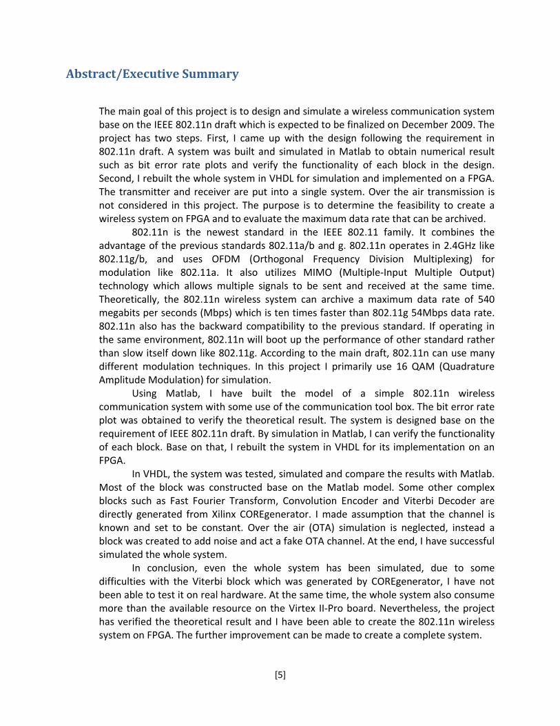
Abstract/Executive Summary
The main goal of this project is to design and simulate a wireless communication system base on the IEEE 802.11n draft which is expected to be finalized on December 2009. The project has two steps. First, I came up with the design following the requirement in 802.11n draft. A system was built and simulated in Matlab to obtain numerical result such as bit error rate plots and verify the functionality of each block in the design. Second, I rebuilt the whole system in VHDL for simulation and implemented on a FPGA. The transmitter and receiver are put into a single system. Over the air transmission is not considered in this project. The purpose is to determine the feasibility to create a wireless system on FPGA and to evaluate the maximum data rate that can be archived.
802.11n is the newest standard in the IEEE 802.11 family. It combines the advantage of the previous standards 802.11a/b and g. 802.11n operates in 2.4GHz like 802.11g/b, and uses OFDM (Orthogonal Frequency Division Multiplexing) for modulation like 802.11a. It also utilizes MIMO (Multiple‐Input Multiple Output) technology which allows multiple signals to be sent and received at the same time. Theoretically, the 802.11n wireless system can archive a maximum data rate of 540 megabits per seconds (Mbps) which is ten times faster than 802.11g 54Mbps data rate. 802.11n also has the backward compatibility to the previous standard. If operating in the same environment, 802.11n will boot up the performance of other standard rather than slow itself down like 802.11g. According to the main draft, 802.11n can use many different modulation techniques. In this project I primarily use 16 QAM (Quadrature Amplitude Modulation) for simulation.
Using Matlab, I have built the model of a simple 802.11n wireless communication system with some use of the communication tool box. The bit error rate plot was obtained to verify the theoretical result. The system is designed base on the requirement of IEEE 802.11n draft. By simulation in Matlab, I can verify the functionality of each block. Base on that, I rebuilt the system in VHDL for its implementation on an FPGA.
In VHDL, the system was tested, simulated and compare the results with Matlab. Most of the block was constructed base on the Matlab model. Some other complex blocks such as Fast Fourier Transform, Convolution Encoder and Viterbi Decoder are directly generated from Xilinx COREgenerator. I made assumption that the channel is known and set to be constant. Over the air (OTA) simulation is neglected, instead a block was created to add noise and act a fake OTA channel. At the end, I have successful simulated the whole system.
In conclusion, even the whole system has been simulated, due to some difficulties with the Viterbi block which was generated by COREgenerator, I have not been able to test it on real hardware. At the same time, the whole system also consume more than the available resource on the Virtex II‐Pro board. Nevertheless, the project has verified the theoretical result and I have been able to create the 802.11n wireless system on FPGA. The further improvement can be made to create a complete system.

[6]
Chapter 1: Overview of the MQP Project
1.1 Objective Wireless communication has become very popular nowadays. The increasing use
of cell phone changed the way people live; we can contact each other just about
anywhere and anytime. The technology and product such as Google allows
people to access and find information like stock information and the whole
Encyclopedia instantly, or instant messenger can help a person to join
conferences or meetings which are happen half way around the world. The rapid
development of wireless LAN also makes everything possible. People do not
need to be in the same spot to solve their problem. Wireless communication
makes this world spin faster.
Wireless technology still has some disadvantage like low data rate and
limit in range. However, the technology has been significantly improved in the
past few years. In 1997, IEEE introduced the 802.11 family standards which is the
most popular standards in the market today. The newest member of the family is
the 802.11n standard. In this project, our objective is to build a wireless system
base on the 802.11n draft using FPGA technology and Xilinx Virtex II Pro core.

[7]
1.2 Technical Approach
Figure 1: The flow of technical approach
The approach for the project is followed the steps in the flow chart above. At the
beginning, we need to do an intensive research to get a clear understanding about
wireless communication. The research included the basic fundamental of wireless
communication, its history. The main focus is the IEEE 802.11 standard family,
especially 802.11n, which this project is mainly based on. The concepts of OFDM and
MIMO communication are very importance to design and implement the 802.11n
standard. They are the backbone to create the 2x2 MIMO wireless system. After
finishing research, we have the clear understanding how to design our own system.

[8]
We came up with our own design which satisfies the requirement from the IEEE
802.11n draft. During the design process, we used Matlab to simulate each block.
Each block as well as the whole system will be tested to verify their functionality.
Base on the result and algorithm of the pre‐build system in Matlab, we build a new
system in VHDL code and Xilinx core gens. After simulation to make sure the system
working properly, we implemented it into Xilinx Virtex 2 Board and collecting the
result data for analysis and conclusion.

[9]
Chapter 2: Background and Motivations
2.1 Introduction to WLAN
Wireless Local Area Network or Wireless LAN is a network that allow users to
connect their devices to a local area network through a wireless (radio) network
connection. The wireless connection uses spread‐spectrum or orthogonal frequency
division multiplexer (OFDM) modulation technology to establish communication
channel between devices in a limited area. This gives users the ability to move
around in the coverage area and still be able to connect [1].
In 1970, University of Hawaii built the first wireless system, the ALOHAnet. The
system composed of several computers which was located over four islands to
communicate with a central computer without phone line. The early wireless LAN
system was expensive; it was only used at place where a cable is difficult to set up.
In 1990s, there were two standards for wireless communication. One is the 802.11,
which was implemented by the IEEE (International Electrical and Electronic
Engineers) LAN committee and the HIPERLAN which was defined by ETSI (European
Telecommunication Standards Institute). However, the HIPERLAN was not success in
the commercial market [1]. Today, 802.11 standards is widely use in wireless
communication world. 802.11 family has growth from 802.11a to 802.11b and
802.11g, the newest member is 802.11n, which is expected to finalize at the end of
2009.
Wireless communications and devices have become popular nowadays due to its
advantages and benefits. Wireless allows user to access network resource from
anywhere within the coverage range like home and office. At the same time, the
increasing of public access point such as Wi‐Fi hotspot, user can be connected from
a place like coffee shop or at the airport. Wireless frees user from being tied down at
one place, it helps increasing work productivity since employee can finish their work
at any convenience location. Wireless communication also offer a lower cost than
wire communication. With the same equipment, wireless network can accept an

[10]
increase number of user without any additional cost and save a significant amount
of space rather than cable. These advantages have made wireless communication
become a very promising field to get into in the future [1].
2.2 802.11 standards
IEEE 802.11 is the set of Wireless LAN standards which was developed by group 11
of IEEE LAN/MAN Standards Committee (IEEE 802). The 802.11 draft was published
in 1997. The name 802.11x was used to denote this set of standards and is not to be
mistake for any one of its elements [1]. The term IEEE 802.11 was used to refer to
the original 802.11 draft, which is called the “802.11 legacy”.
802.11 standard layouts rule for manufacture to product their wireless devices
to be compatible with others in the same standards. The family currently included
six over‐the‐air modulation techniques which use the same protocol. The most
popular techniques are those in 802.11 a, b and g. 802.11a and 802.11b were
introduced in the same year, however 802.11b achieve more commercial successful
and was followed by the 802.11g. The newest 802.11n standard is still under
development and is expected to be finalized at the end of 2009. At the same time,
IEEE has started for a new draft such as 802.11v, s and p.
802.11 standard family operates in the 2.4, 3.6 and 5 GHz bandwidth. The
original 802.11 legacy specified two raw data rates of 1 and 2 megabits per second
(Mbits/s) to be transmitted via infrared (IR) signal or by either Frequency hopping
and Direct‐sequence spread spectrum in the ISM band at 2.4GHz [1]. The original
standard is somewhat a beta specification that allow producer to develop their own
product. 802.11 become more popular over the HIPERLAN standards after the
appearance of the 802.11b and it has widespread to be the world standard for
Wireless Communication.
[11]
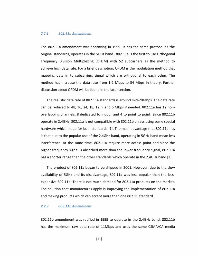
2.2.1 802.11a Amendment
The 802.11a amendment was approving in 1999. It has the same protocol as the
original standards, operates in the 5GHz band. 802.11a is the first to use Orthogonal
Frequency Division Multiplexing (OFDM) with 52 subcarriers as the method to
achieve high data rate. For a brief description, OFDM is the modulation method that
mapping data in to subcarriers signal which are orthogonal to each other. The
method has increase the data rate from 1‐2 Mbps to 54 Mbps in theory. Further
discussion about OFDM will be found in the later section.
The realistic data rate of 802.11a standards is around mid‐20Mbps. The data rate
can be reduced to 48, 36, 24, 18, 12, 9 and 6 Mbps if needed. 802.11a has 12 non‐
overlapping channels, 8 dedicated to indoor and 4 to point to point. Since 802.11b
operate in 2.4GHz, 802.11a is not compatible with 802.11b unless using some special
hardware which made for both standards [1]. The main advantage that 802.11a has
is that due to the popular use of the 2.4GHz band, operating in 5GHz band mean less
interference. At the same time, 802.11a require more access point and since the
higher frequency signal is absorbed more than the lower frequency signal, 802.11a
has a shorter range than the other standards which operate in the 2.4GHz band [2].
The product of 802.11a began to be shipped in 2001. However, due to the slow
availability of 5GHz and its disadvantage, 802.11a was less popular than the less‐
expensive 802.11b. There is not much demand for 802.11a products on the market.
The solution that manufactures apply is improving the implementation of 802.11a
and making products which can accept more than one 802.11 standard.
2.2.2 802.11b Amendment
802.11b amendment was ratified in 1999 to operate in the 2.4GHz band. 802.11b
has the maximum raw data rate of 11Mbps and uses the same CSMA/CA media

[12]
access as the original standards. The practice maximum data rate of 802.11b is
5.9Mbps using TCP and 7.1Mbps using UDP [1].
Although making appearance on the market at the same time, 802.11b gained
more acceptance than 802.11a. The main reason was that 802.11b use the direct
extension of DSSS (Directed sequence spread spectrum) modulation technique
which defined in the original standards. Hence, the products for 802.11b were easier
to manufacture by updating the chipsets. It also offer a lower cost than the 802.11a,
as the result 802.11b became the definitive Wireless LAN technology.
The draw back from 802.11b is that it has the slower data rate and the
unregulated 2.4GHz may be interfered by other home equipment when set up [3].
On the other hand, the lower frequency signal and lower data rate use the less
complex method to encode data. The signal can avoid corruption from interfering
and signal attenuation [1]. There is an extension which called the 802.11b+ because
it was not enclosed by IEEE. The extension has the data rate up to 54Mbps and
backward‐compatible with 802.11b.
2.2.3 802.11g Amendment
The third standard was ratified in June 2003, the 802.11g. It contains the
characteristic of the two previous standards. In the favor of 802.11b, 802.11g
operate in the same 2.4GHz band but use OFDM to achieve the data rate of 54Mbps
like 802.11a. 802.11g also contain DSSS scheme to be able to backward‐compatible
with 802.11b. The data rate and range of 802.11g is higher than 802.11b. But to
reach the maximum data rate, the range if much shorter than 802.11b. When
operate in the same environment with 802.11b, the data rate of 802.11g product
will be reduced 11Mbps the same with 802.11b.
When it was introduced, 802.11g was a big success. Most of the dual band
product for 802.11a/b became tri‐band that supports 802.11a/b and g. On the other
hand, 802.11g suffered from signal interfering because there are just too many

[13]
other devices use the same 2.4GHz band such as microwave ovens, Bluetooth
devices and cordless telephone [1].
2.3 802.11n
July 2003, 802.11n task group was formed to create the new Wireless LAN standards
with the goal to reach up to 100Mbps data rate. The proposal for the new standard
included MIMO‐OFDM, 20 and 40MHz channels, and packet aggregation techniques.
July 2005, a new group was formed to create the first draft of 802.11n standard [4].
Table 1: Mandatory Modulation and coding scheme (MSC) [4]
Table 1 shows the modulation and coding schemes and their corresponding data
rate. The figure below describes the functional block in the design of 802.11n
transmitter:

[14]
Figure 2: Block diagram for 802.11 transmitter
According to 802.11n standard, the input data is scrambler using the same
length 127 pseudo‐noise scrambler like the 802.11a. The data continue through the
convolution encoder which is also the same with 802.11a, the only different is that
in the 3 and 4 spatial stream, the odd and even bits are encoded by two different
encoder to ensure the limit the maximum decoding rate at the receiver [4].
A parser then divides the data into block s max N , 1 bits into different
spatial stream, where Nbpsc is the number of bit per subcarrier. The blocks of data
are rearranged by the block Interleaver to ensure the spatial and frequencies
diversify. The block has the size equal to the number of bit per OFDM simple of nth
spatial stream, NCBPS,n. The Interleaver index for spatial stream n within the block of
NCBPS,n is define by these equation below, where kn is the input bit index and jn is the
output bit index:

[15]
Table 2: Interleaver parameter (IDEPTH) [4]
After interleaving, the bits are converted into QAM symbols. Then a spatial
mapping matrix is applied to convert NSS, spatial stream input into Ntx transmitter
output. Unlike 802.11a/b and g which only have one spatial stream, 802.11n require
several spatial streams depend on the requirement to implement MIMO. IFFT is
applied to perform OFDM at the end before transmitting.
2.4 Introduction to MIMOOFDM systems
2.4.1 OFDM
OFDM stands for Orthogonal Frequency Division Multiplexing. It is a combination
between modulation and multiplexing. Modulation means mapping the original
information into new symbol which has frequency, phase and amplitude.
Multiplexing refers to combination of independence signals which produces by
difference source. Therefore, OFDM can be understand as a method that first
split the original data into independence channels, modulated the data and re‐
multiplexed to create OFDM carriers. OFDM is the special case of Frequency
Division Multiplex (FDM). In FDM, the data comes in one stream and cannot be
divided. In OFDM, the information is made up by many smaller streams [5].
Figure 3: FDM [2]
[16]
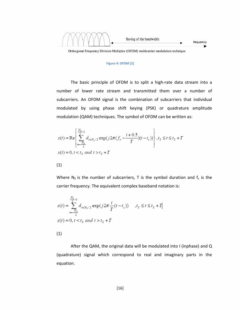
Figure 4: OFDM [2]
The basic principle of OFDM is to split a high‐rate data stream into a
number of lower rate stream and transmitted them over a number of
subcarriers. An OFDM signal is the combination of subcarriers that individual
modulated by using phase shift keying (PSK) or quadrature amplitude
modulation (QAM) techniques. The symbol of OFDM can be written as:
(1)
Where NS is the number of subcarriers, T is the symbol duration and fc is the
carrier frequency. The equivalent complex baseband notation is:
(1)
After the QAM, the original data will be modulated into I (inphase) and Q
(quadrature) signal which correspond to real and imaginary parts in the
equation.

[17]
Figure 5: OFDM modulator [6]
The main concept in OFDM is the orthogonal of subcarriers. Each carrier
is represented as sine or cosine wave, the area under one period of each wave is
zero. Orthogonal allow simultaneous transmission on a lot of subcarriers in a
short frequency without interference with each others. OFDM uses Discrete
Fourier Transform (DFT) to map the input to a set of orthogonal basis function. In
particle, it is more efficient to use to Fast Fourier Transform (FFT) to implement
DFT. According to 802.11n standards, the inverse Fast Fourier Transform (IFFT) is
used in the transmitter and FFT is used in the receiver. IFFT significant reduces
the amount of calculation rather than the IDFT (inverse DFT).
The formulas for FFT and IFFT are:
Using IFFT and FFT in sequence will give back the original data.

[18]
Figure 6: Fast Fourier Transform [5]
OFDM signals offers advantage that reduce the fading effect during the
transmitting process. In the path from the transmitter to the receiver, there are
reflections and obstructions that have negative effect on the signals or the
fading effect. The original signal can reach the target in difference routes which
can result delay and gain in the receiving side.
Figure 7: Fading path
With OFDM signal is divided into smaller subcarrier, during the
transmitting, OFDM signal can avoid that all of the subcarrier being damaged by
fading effect. Therefore, instead of the whole signal being smashed up, we will
lose just a small subset of bits at the receiving end, with a proper error‐
correcting code; we can easily recover the whole original signal.

[19]
2.4.2 MIMO
When it comes to wireless communication, fundamental problems include
obstruction between the path of the transmitter and receiver, moving receiver
terminal, reflection, scattering, etc… The effects of multipath fading will happen
when there are multi reflections of the same signal. As we mention in the
previous section, signal is electromagnetic waves travel at different travelling
path cause the same signal to arrive at different time and from different
direction which produce out of phase waves. In 802.11n standard, to fix these
problems, a Multiple‐Input Multiple‐Output (MIMO) has been implemented. The
main advantage of MIMO implementation is the increase of network
performance and improved Bit‐Error Rate (BER). There are two methods for
MIMO implementation: Beamforming and Space Time Block Code (STBC).
In a brief description, MIMO is the technique for booting wireless
bandwidth and range by using the advantage of multiplexing. It sometimes called
the spatial diversifies because it uses multiple spatial channels for data
transmission and reception. MIMO is mainly used in 802.11n but it can be
applied into other 802.11 standards. The concept of MIMO in 802.11n standards
come from the Alamouti Scheme which introduced in 1998 by Siavash M.
Alamouti.
The Alamouti Scheme:
In the issue or IEEE Journal in 1998, Alamouti presented the two brands transmit
diversify scheme with the same order with the Maximal‐Ratio Receive Combining
(MRRC) scheme:
R hS n h e

[20]
Where R is the receive signal, S is the original signal, h is a complex variable
which consist of the sum of two Gaussian Distributions and n is the complex
noise and interference. A two brand MMRC system is represented in the figure
below:
Figure 8: MIMO one transmitter, two receivers [7]
The system has one transmitter and two receivers, the maximum ratio will take
the signal from two received then construct the original signal. Alamouti
introduced the new transmit diversity scheme: two brands transmit diversity
with one receiver:

[21]
Figure 9: MIMO two transmitters, one receiver [7]
Table 3: Alamouti Scheme
Antenna 0 Antenna1 Time t Time t+T ‐
Encoding table of the transmitter is shown above. At the same period,
two signals are simultaneously transmitted from two antennas. The signal s0 is
transmitted from antenna 0 and s1 from antenna 1. In the next period, (‐s ),
which is the negative of the conjugate of s1 is transmitted at antenna 0 and
conjugate of s0 is transmitted from antenna 1.
Base on this concept, Alamouti also introduce a new concept for 2x2
MIMO systems with two transmitters and two receivers:

[22]
Figure 10: 2x2 MIMO [7]
In this project, we will design a system base on the 2x2 MIMO Alamouti Scheme.

[23]
Chapter 3: System Design and Matlab Simulation
Base on the 802.11n draft, we come up with the design for our wireless system.
The system is described in the block diagram below:
Figure 11: Wireless Communication System Block Diagram
For the better understand of the whole system, we will explain the
function of each block in the next section. At the same time, Base we build out
first wireless system on Matlab. The system includes the components as see in
Figure 11. In the design of the system, we chose the data block of 52 bits to
compromise the requirement data block size to be the multiple of Idepth = 13.
Therefore, for the Matlab simulation, we started with 26 bits random data:
[24]
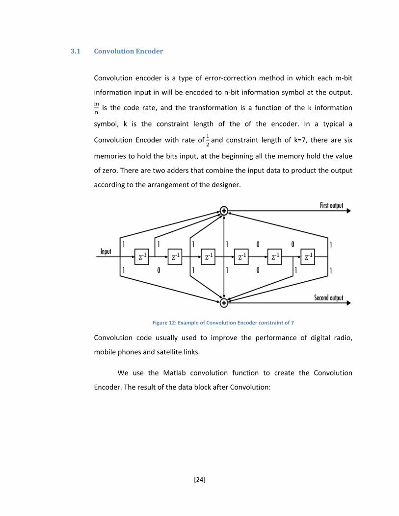
3.1 Convolution Encoder
Convolution encoder is a type of error‐correction method in which each m‐bit
information input in will be encoded to n‐bit information symbol at the output.
is the code rate, and the transformation is a function of the k information
symbol, k is the constraint length of the of the encoder. In a typical a
Convolution Encoder with rate of and constraint length of k=7, there are six
memories to hold the bits input, at the beginning all the memory hold the value
of zero. There are two adders that combine the input data to product the output
according to the arrangement of the designer.
Figure 12: Example of Convolution Encoder constraint of 7
Convolution code usually used to improve the performance of digital radio,
mobile phones and satellite links.
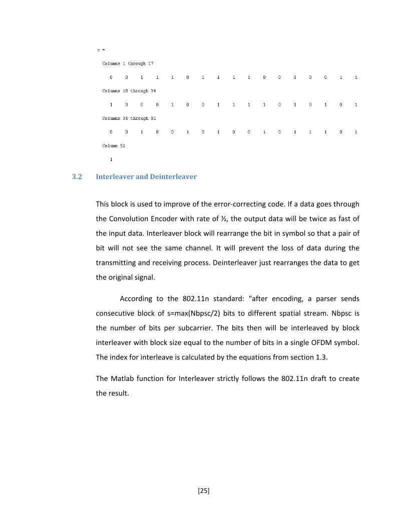
We use the Matlab convolution function to create the Convolution
Encoder. The result of the data block after Convolution:
[25]
3.2 Interleaver and Deinterleaver
This block is used to improve of the error‐correcting code. If a data goes through
the Convolution Encoder with rate of ½, the output data will be twice as fast of
the input data. Interleaver block will rearrange the bit in symbol so that a pair of
bit will not see the same channel. It will prevent the loss of data during the
transmitting and receiving process. Deinterleaver just rearranges the data to get
the original signal.
According to the 802.11n standard: “after encoding, a parser sends
consecutive block of s=max(Nbpsc/2) bits to different spatial stream. Nbpsc is
the number of bits per subcarrier. The bits then will be interleaved by block
interleaver with block size equal to the number of bits in a single OFDM symbol.
The index for interleave is calculated by the equations from section 1.3.
The Matlab function for Interleaver strictly follows the 802.11n draft to create
the result.

[26]
3.3 Quadrature Amplitude Modulation
This is a digital modulation technique that maps binary information using the
gray code maps. The output after modulation is a complex signal which can be
use to transfer through the physical channel. There are different from of QAM, in
this case we use the 16‐QAM. The Gray code map below give a visual description
for the modulation method:
Figure 13: 16‐QAM mapping scheme

[27]
The vertical axis is Quadrature component (Q signal) and the horizontal
axis is the Inphase component (I signal).
I and Q signal are the component to form sinusoidal carriers that are
orthogonal with respect with each others. The signal can be represent as
cos sin
The 16‐QAM modulation processes data to create I and Q signal. First, it will
group the bit into symbol of four bits, and then map the symbol according to the
Gray code:
A notice here is that to prepare for the Alamouti encoder, the number of
symbol in the data block must be 2xn, therefore a null symbol was added at the
end to make the number of symbol to be even.
3.4 Alamouti Encoder and Decoder
In this project, we implemented a 2x2 MIMO base on the Alamouti Scheme from
chapter 1.4.2. The concept of 2x2 MIMO can be seen in Figure 10. Data from the
16‐QAM will be encoded into two separate signal in Table 3. During the
transmitting process, there are notations for channel and receiving signal from
transmit antenna and receive antenna. The Table 4 and 5 describe the
relationship of each notation with the transceiver:

[28]
Table 4: Channel notation between transmit and receive antenna [7]
Rx antenna 0 Rx antenna 1
Tx antenna 0
Tx antenna 1
Table 5: Notation for receive signal at receiver side [7]
Rx antenna 0 Rx antenna 1
Time t
Time t + T
The relationship between these notations and the original signal is:
Where n , n , n , and n are the complex variable representing for noise and
interference from during the transmitting [7].
After the receiver gets the signal, the data must pass through the
Alamouti Decoder to get the original data symbol. The decoder is composed by a
combiner and a maximum likelihood detector. The combiner add the notation
above together which has the result as:
[7]
The result will be process through the maximum likelihood detector to get the
original symbol.

[29]
Alamouti encoder takes in one stream of data and rearranges it into two data
stream follow the rule in table 3:
3.5 Inverse and Forward Fast Fourier Transform
As we already knew from previous chapter, IFFT and FFT is the main
fundamental to implement OFDM, IFFT for transmitter and FFT for receiver. I and
Q signal from 16‐QAM are represented for the real and imagine.
To implement the OFDM, we use IFFT to arrange data into orthogonal signal:

[30]
Follow the Alamouti Scheme draft, a channel block was built to add noise and
channel estimation in the data during the transmitting process. For the first
simulation, we assume there are no noise and the channel estimation
h0 = h1 = h2 = h3 = 1
The data at the receive antenna is:

[31]
After FFT, the data retrieving data is:
After the combination and maximum likelihood detector, we come up with the
answer:

[32]
The rest of the work is put the data through D‐QAM and Deinterleaver:
3.6 Viterbi decoder
This block uses the Viterbi algorithm for decoding a bit steam that has been
encoded using the forward error‐correcting code base on the Convolution
[33]
encoder. This is one of the most resource consuming blocks because it does the
maximum likelihood detector. The decoder takes in the encoded data and
decode it using the trace back to get the most possible data output.
Compare to the initial input, the decoded data is identical. Base on the
algorithm that is used to build the Matlab simulation, we develop the VHDL code
and simulation of the wireless system.
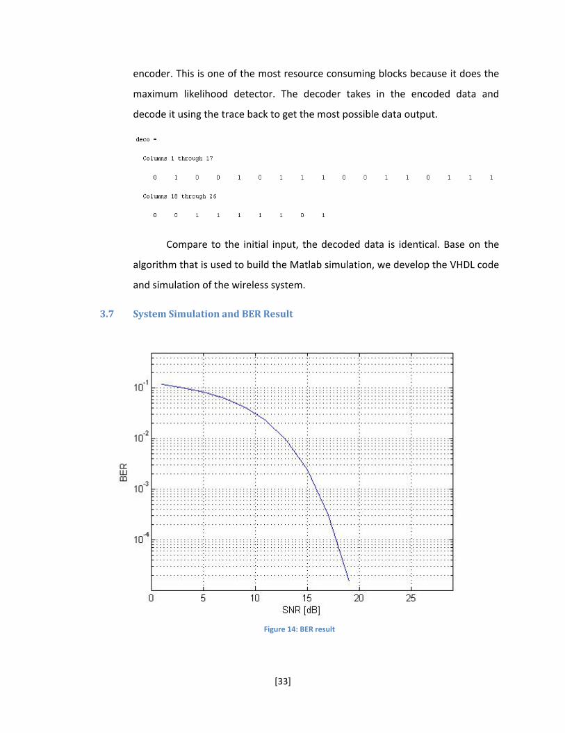
3.7 System Simulation and BER Result
Figure 14: BER result

[34]
The BER plot has verified the functionality of the wireless system to
satisfy the 802.11n draft requirement. This graph is simulated from a 1x1 OFDM
system.

[35]
Chapter 4 HDL Design and Simulation
Field‐Programmable Gate Array or FPGA is a silicon chip that contains an array of
configurable logic block (CLB). Unlike Application Specific Integrated Circuit
(ASIC) which can only be programmed once and performs a single function for a
life time, and FPGA chip can be reprogrammed many times in the matter of
second depend on the need of designer [8]. FPGA provides the flexibility for
designer while increase the complexity of the program. The reprogram ability
also makes FPGA become popular among hardware designer for prototype
circuit. There are three main advantages in using FPGA. First of all, it consumes
less power than conventional microprocessors. Secondly, we can significantly
increase computer density and last of all, FPGA can increase performance for a
certain application significantly.
We use VHDL and Xilinx Core generator to design and implemented our new
wireless system base on the 802.11n draft.
4.1 Random data generator
To test the system, first we need to come up with a way to generate a random
data. A LFSR (Linear Feedback Shift Register) concept is used to create the
random bit generator. LFSR is a shift register whose input bit is a linear function
of its previous state. The only linear function of a single bit are xor (exclusive‐or).
There is an initial value which is called seed; the stream value produced by the
register is completely determined by the current (previous) state.

[36]
Figure 15: LFSR
In the design, it is flexible to change seed to create different stream of
data. When the Start input is active high for one clock cycle, the data stream of
data will come out. The number of bit is base on our modification of the code.
For the simulation, the seed is set to be h’AD and the number of data is 50 bits.
Here is the simulation result for the random bit stream.
Figure 16: Random number generator
Synthesize report:
================================================================== HDL Synthesis Report Macro Statistics # Adders/Subtractors : 1 32‐bit adder : 1 # Registers : 4 1‐bit register : 2 32‐bit register : 1 8‐bit register : 1 # Comparators : 4 32‐bit comparator greater : 2 32‐bit comparator lessequal : 2 # Multiplexers : 1 32‐bit 4‐to‐1 multiplexer : 1 # Xors : 1 1‐bit xor3 : 1 ================================================================== Advanced HDL Synthesis Report
[37]
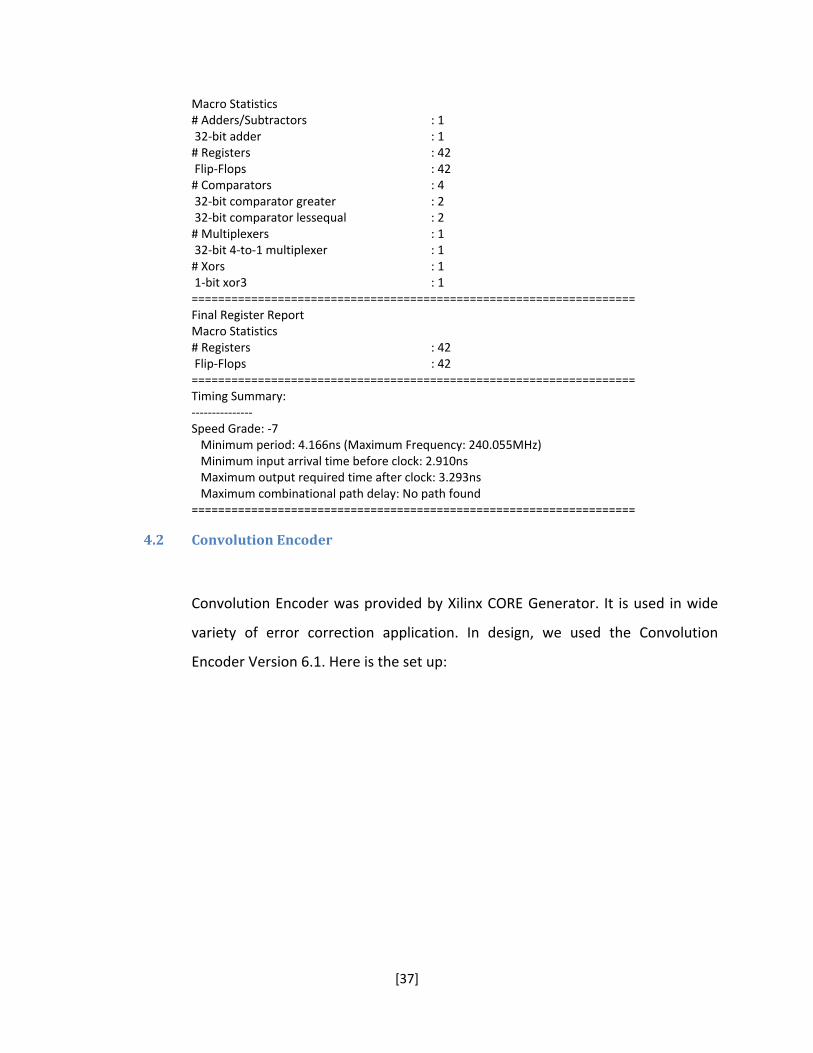
Macro Statistics # Adders/Subtractors : 1 32‐bit adder : 1 # Registers : 42 Flip‐Flops : 42 # Comparators : 4 32‐bit comparator greater : 2 32‐bit comparator lessequal : 2 # Multiplexers : 1 32‐bit 4‐to‐1 multiplexer : 1 # Xors : 1 1‐bit xor3 : 1 =================================================================== Final Register Report Macro Statistics # Registers : 42 Flip‐Flops : 42 =================================================================== Timing Summary: ‐‐‐‐‐‐‐‐‐‐‐‐‐‐‐ Speed Grade: ‐7 Minimum period: 4.166ns (Maximum Frequency: 240.055MHz) Minimum input arrival time before clock: 2.910ns Maximum output required time after clock: 3.293ns Maximum combinational path delay: No path found ===================================================================
4.2 Convolution Encoder
Convolution Encoder was provided by Xilinx CORE Generator. It is used in wide
variety of error correction application. In design, we used the Convolution
Encoder Version 6.1. Here is the set up:

[38]
Figure 17: Convolution Encoder set up
In the Data Rates, the encoder rate is set to 1/2, which means that for every bit
input, there will be two bits output. The Constraint length is set to 7 and
Convolution code is [171 133] in octal number. For the in definition:
Data_in: one bit data stream
ND: active high ‐ send the signal that there is input data.
RDY: active high – confirm the data output
ACLR and SCLR: active high – reset signal
CE: active high – Chip enable
Data‐out: 2 bits output data
The simulation result is shown below:

[39]
Figure 18: Convolution Simulation Result
Data_out_v:
h’ 0 3 2 1 1 0 2 3 3 3 0 3 2 3 2 0 0 2 1 2 0 3 0 3 3 0 1 0 0 2 0 1 0 0 2 1 3 3
3 1 0 2 2 1 0 3 1 1 2 3 1 1
Synthesize report:
================================================================== HDL Synthesis Report Found no macro ================================================================== Advanced HDL Synthesis Report Found no macro ================================================================== ================================================================== Advanced HDL Synthesis Report Found no macro ================================================================== Timing Summary: ‐‐‐‐‐‐‐‐‐‐‐‐‐‐‐ Speed Grade: ‐7 Minimum period: 2.000ns (Maximum Frequency: 499.875MHz) Minimum input arrival time before clock: 2.444ns Maximum output required time after clock: 3.900ns Maximum combinational path delay: No path found ==================================================================
When synthesizing for Convolution block, the block was created by
COREgen, the simulation and implementation still work but the report will show
no macro. The same apply the FFT and Viterbi block.
4.3 Interleaver and Deinterleaver

[40]
Interleaver and Deinterleaver are conjunction of each others. Interleaver will
rearrange data to make sure diversify of bit during the transmit process. The
operation of Interleaver and Deinterleaver black have been verify in the Matlab
simulation.
Figure 19: Interleaver Block
In VHDL design, Interleaver block received data input D_in(1:0) from
Convolution Encoder. There are two steps in the process, since the data block in
802.11n is defined to be 52 bits; there is a memory that collect data until the
number of bit meet the requirement. Incase if the sum of all the bits is not the
multiple of 52, the Interleaver will automatically add zero bits at the end of the
data block. The output index was mapped base on the result from Matlab. The
output index is fixed and is not flexible to modify:
The simulation result from Interleaver:
[41]
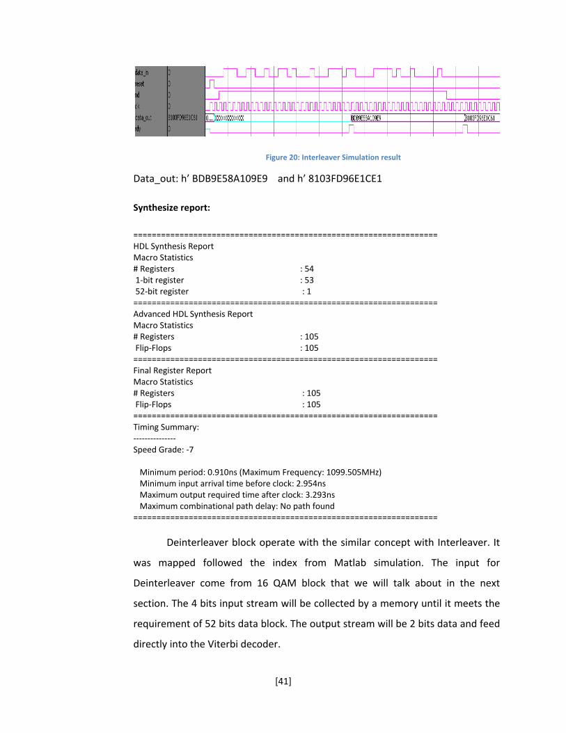
Figure 20: Interleaver Simulation result
Data_out: h’ BDB9E58A109E9 and h’ 8103FD96E1CE1
Synthesize report:
================================================================== HDL Synthesis Report Macro Statistics # Registers : 54 1‐bit register : 53 52‐bit register : 1 ================================================================== Advanced HDL Synthesis Report Macro Statistics # Registers : 105 Flip‐Flops : 105 ================================================================== Final Register Report Macro Statistics # Registers : 105 Flip‐Flops : 105 ================================================================== Timing Summary: ‐‐‐‐‐‐‐‐‐‐‐‐‐‐‐ Speed Grade: ‐7 Minimum period: 0.910ns (Maximum Frequency: 1099.505MHz) Minimum input arrival time before clock: 2.954ns Maximum output required time after clock: 3.293ns Maximum combinational path delay: No path found ==================================================================
Deinterleaver block operate with the similar concept with Interleaver. It
was mapped followed the index from Matlab simulation. The input for
Deinterleaver come from 16 QAM block that we will talk about in the next
section. The 4 bits input stream will be collected by a memory until it meets the
requirement of 52 bits data block. The output stream will be 2 bits data and feed
directly into the Viterbi decoder.

[42]
Figure 21: Deinterleaver Block
For the simulation result, first we will look at the input data:
Figure 22: Simulation input to Deinterleaver
These values come from the 16 D‐QAM that we will talk about in the next
section, the result at the end of QAM is:
Figure 23: Deinterleaver Simulation Result
to_data : h’ 0 3 2 1 1 0 2 3 3 3 0 3 2 3 2 0 0 2 1 2 0 3 0 3 3 0 1 0 0 2 0 1 0 0 2 1 3 3

[43]
3 1 0 2 2 1 0 3 1 1 2 3 1 0
Synthesize report:
================================================================== HDL Synthesis Report Macro Statistics # Registers : 54 1‐bit register : 53 52‐bit register : 1 ================================================================== Advanced HDL Synthesis Report Macro Statistics # Registers : 105 Flip‐Flops : 105 ================================================================== Final Register Report Macro Statistics # Registers : 105 Flip‐Flops : 105 ================================================================== Timing Summary: ‐‐‐‐‐‐‐‐‐‐‐‐‐‐‐ Speed Grade: ‐7 Minimum period: 0.910ns (Maximum Frequency: 1099.505MHz) Minimum input arrival time before clock: 2.954ns Maximum output required time after clock: 3.293ns Maximum combinational path delay: No path found ==================================================================
4.4 16 QAM and DQAM
16 QAM convert the data into complex signal which compose by the real (I) and
imagine (Q) parts. This block takes in input from Interleaver block, the input in
parallel form of 52 bits. 16 QAM will make the data into serial from and output
as smaller block of 4 bits and then map them according to the Gray Code map in
figure 13.
[44]
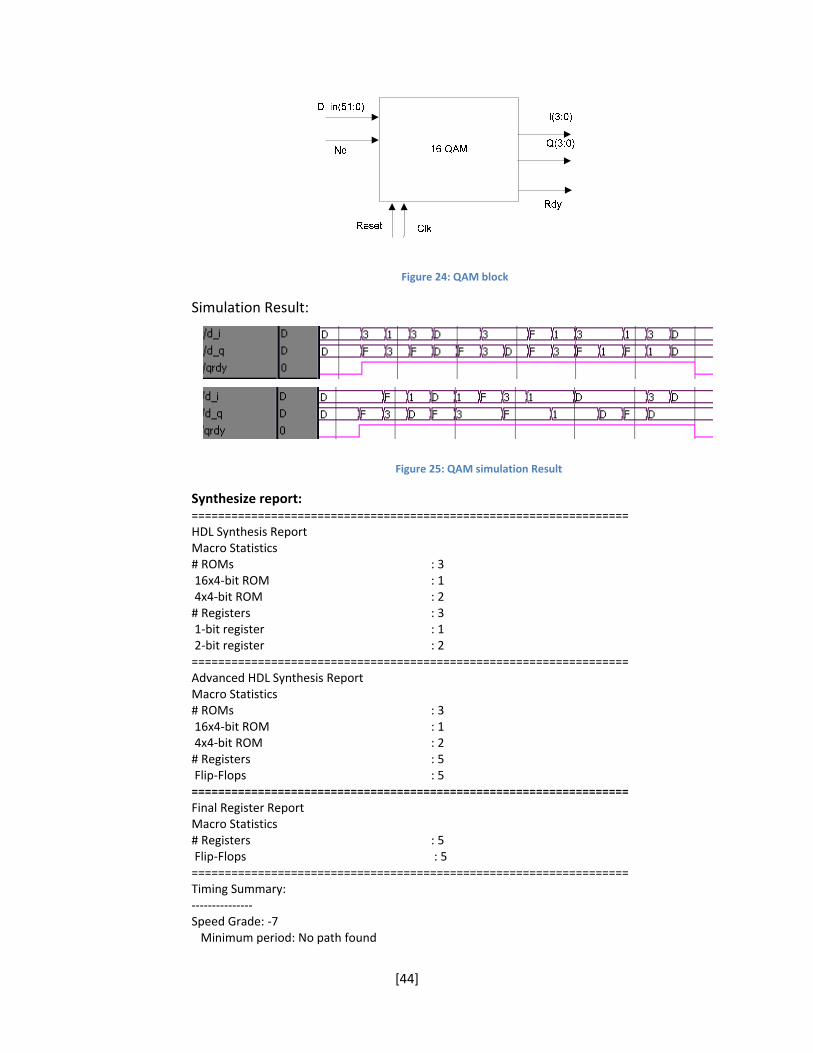
Figure 24: QAM block
Simulation Result:
Figure 25: QAM simulation Result
Synthesize report: ================================================================== HDL Synthesis Report Macro Statistics # ROMs : 3 16x4‐bit ROM : 1 4x4‐bit ROM : 2 # Registers : 3 1‐bit register : 1 2‐bit register : 2 ================================================================== Advanced HDL Synthesis Report Macro Statistics # ROMs : 3 16x4‐bit ROM : 1 4x4‐bit ROM : 2 # Registers : 5 Flip‐Flops : 5 ================================================================== Final Register Report Macro Statistics # Registers : 5 Flip‐Flops : 5 ================================================================== Timing Summary: ‐‐‐‐‐‐‐‐‐‐‐‐‐‐‐ Speed Grade: ‐7 Minimum period: No path found
[45]
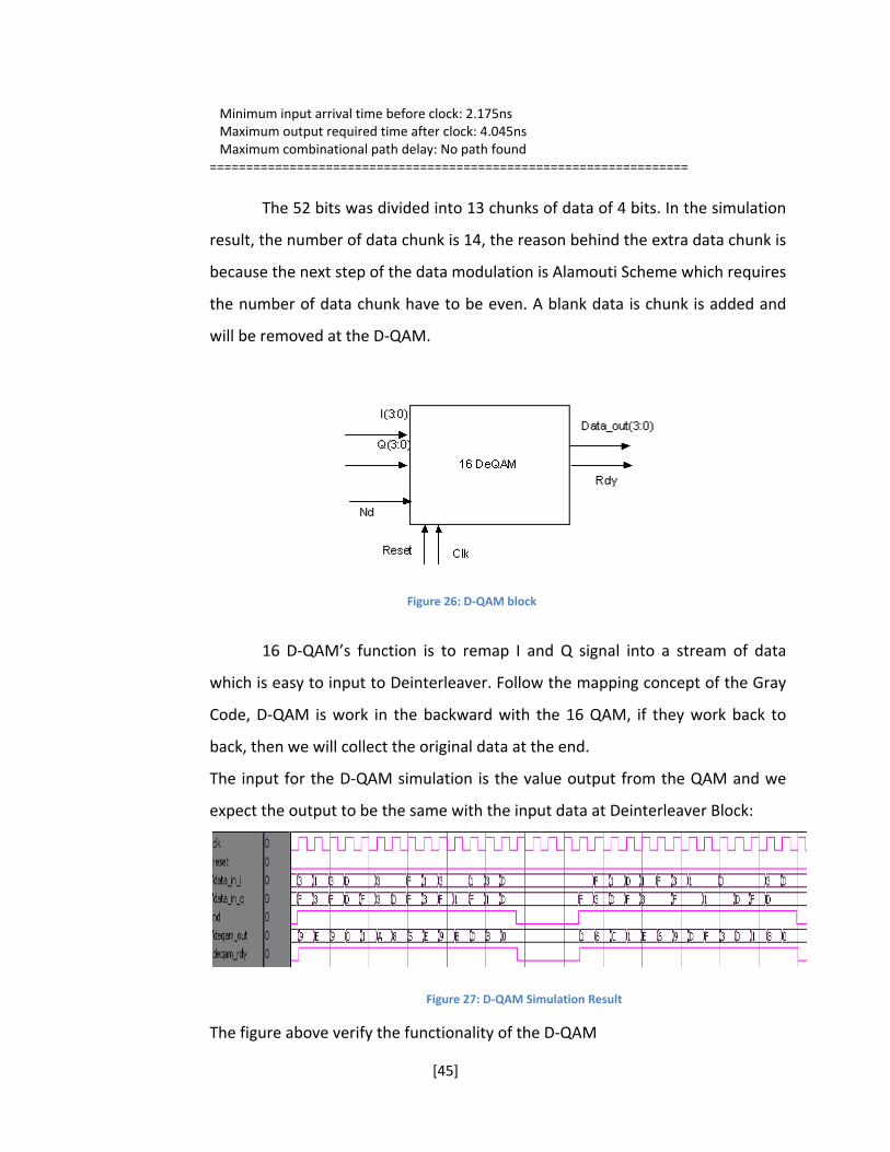
Minimum input arrival time before clock: 2.175ns Maximum output required time after clock: 4.045ns Maximum combinational path delay: No path found ==================================================================
The 52 bits was divided into 13 chunks of data of 4 bits. In the simulation
result, the number of data chunk is 14, the reason behind the extra data chunk is
because the next step of the data modulation is Alamouti Scheme which requires
the number of data chunk have to be even. A blank data is chunk is added and
will be removed at the D‐QAM.
Figure 26: D‐QAM block
16 D‐QAM’s function is to remap I and Q signal into a stream of data
which is easy to input to Deinterleaver. Follow the mapping concept of the Gray
Code, D‐QAM is work in the backward with the 16 QAM, if they work back to
back, then we will collect the original data at the end.
The input for the D‐QAM simulation is the value output from the QAM and we
expect the output to be the same with the input data at Deinterleaver Block:
Figure 27: D‐QAM Simulation Result
The figure above verify the functionality of the D‐QAM

[46]
Synthesize report:
================================================================== HDL Synthesis Report Macro Statistics # Registers : 2 1‐bit register : 1 4‐bit register : 1 ================================================================== Advanced HDL Synthesis Report Macro Statistics # Registers : 5 Flip‐Flops : 5 ================================================================== Final Register Report Macro Statistics # Registers : 5 Flip‐Flops : 5 ================================================================== Timing Summary: ‐‐‐‐‐‐‐‐‐‐‐‐‐‐‐ Speed Grade: ‐7 Minimum period: No path found Minimum input arrival time before clock: 2.175ns Maximum output required time after clock: 3.293ns Maximum combinational path delay: No path found ==================================================================
4.5 Alamouti Scheme
Encoder
According to Alamouti Scheme in section 3.4, the Alamouti Encoder will
rearrange the data follow the rule of table 3. The design of the encoder is simple,
there are a memory inside that wait until it take in 2 data block then output
them as S0 and S1. The delay between input and output is 3 clock cycles. The
output will be going to through IFFT later to create OFDM scheme.

[47]
Figure 28: Alamouti Encoder Block
Figure 29: Alamouti Encoder Simulation Result
The two data streams are transmitted at two antennas for 2x2 MIMO
implementation.
Synthesize report:
================================================================== HDL Synthesis Report Macro Statistics # Adders/Subtractors : 2 4‐bit adder : 2 # Registers : 19 1‐bit register : 2 32‐bit register : 12 4‐bit register : 5 # Multiplexers : 2 32‐bit 4‐to‐1 multiplexer : 2 ================================================================== Advanced HDL Synthesis Report

[48]
Macro Statistics # Adders/Subtractors : 2 4‐bit adder : 2 # Registers : 70 Flip‐Flops : 70 # Multiplexers : 2 32‐bit 4‐to‐1 multiplexer : 2 ================================================================== Final Register Report Macro Statistics # Registers : 72 Flip‐Flops : 72 ================================================================== Timing Summary: ‐‐‐‐‐‐‐‐‐‐‐‐‐‐‐ Speed Grade: ‐7 Minimum period: 2.238ns (Maximum Frequency: 446.877MHz) Minimum input arrival time before clock: 2.845ns Maximum output required time after clock: 3.293ns Maximum combinational path delay: No path found ==================================================================
Decoder
Figure 30: Alamouti Decoder
In his paper about 2x2 MIMO, the decoder is made by a channel
estimator, a combiner and a maximum likelihood detector. In this project
simulation, the channel estimator is neglected and channel is assumed to be
known. The difficult task here is to design the combiner for complex number in
VHDL. During the calculation of the combiner, there is add, subtract, conjunction
and multiple operation for two complex number. The adding, subtracting and
conjunction operation do not take a lot of memory, they are just simple bit
operation. However, multiple operation consume a lot of hardware resort, we

[49]
need to minimize it use as much as possible. For the design, we used four
multipliers for each channel combiner in r0, r1, r2 and r3. The combiner
performs the same operation as in the function in section 3.4.
The maximum likelihood detector MLD is trailing the result base on the Matlab
algorithm. The value of come out from the Alamouti Encoder goes through IFFT,
then adding noise and channel during the over the air transmitting process. At
the receiver end, the data once more time goes through FFT, the output data is
not quite the result that we expect, because during this process, noise and
channel has adding a significant of unnecessary information into out symbol. To
design the MLD, the extra noise signal is denoted as:
k = |h0|+|h1|+|h2|+|h3|+|n0|+|n1|+|n2|+|n3|
Since noise is not possible to know exactly, we give the sum on noise an roughly
estimate of 4.
Figure 31: Choosing Scheme for Alamouti Decoder
As the figure above, the mapping is divided into small sub area. Depend
on which area that the result comes out land on will determinate the value for
the outcome. All the value in the figure will be scale by the factor k to make sure
that it will contain all the value and the measure is precise.
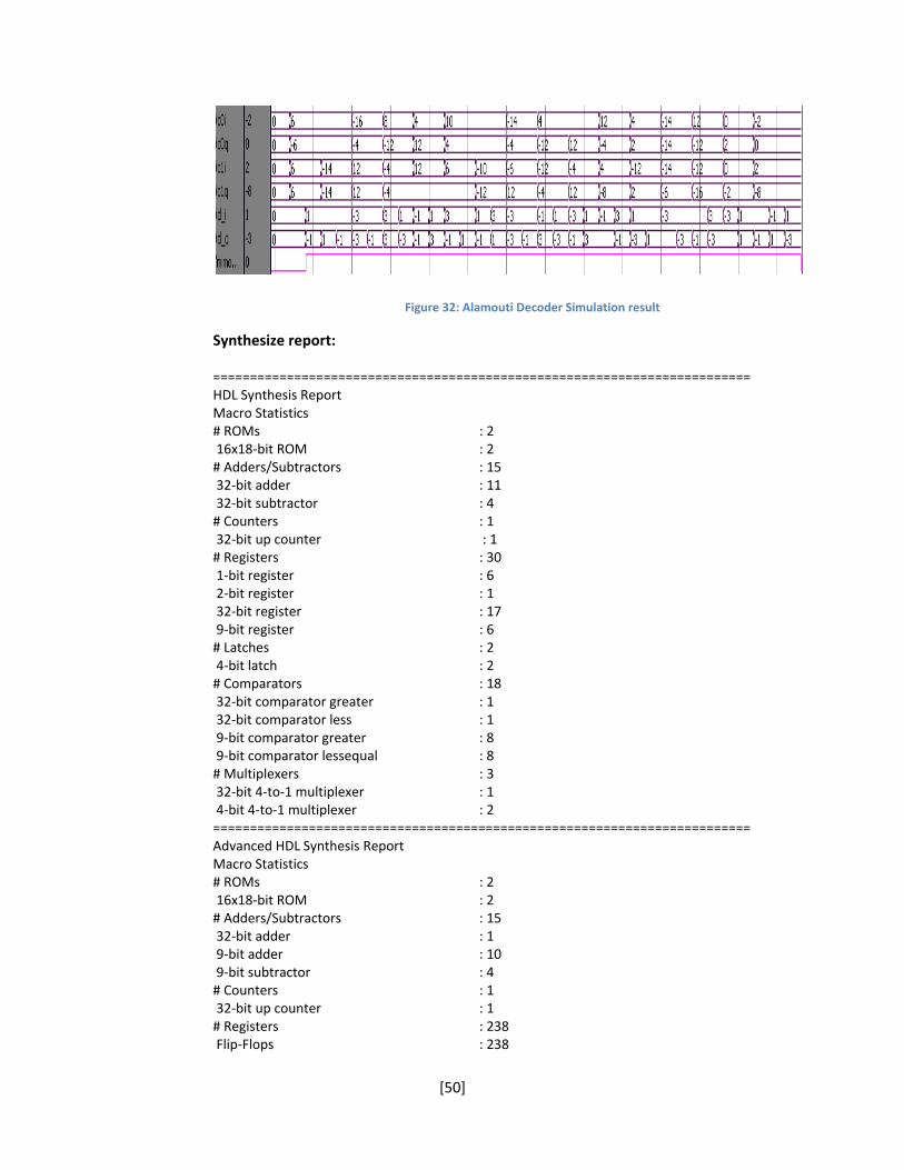
[50]
Figure 32: Alamouti Decoder Simulation result
Synthesize report:
========================================================================= HDL Synthesis Report Macro Statistics # ROMs : 2 16x18‐bit ROM : 2 # Adders/Subtractors : 15 32‐bit adder : 11 32‐bit subtractor : 4 # Counters : 1 32‐bit up counter : 1 # Registers : 30 1‐bit register : 6 2‐bit register : 1 32‐bit register : 17 9‐bit register : 6 # Latches : 2 4‐bit latch : 2 # Comparators : 18 32‐bit comparator greater : 1 32‐bit comparator less : 1 9‐bit comparator greater : 8 9‐bit comparator lessequal : 8 # Multiplexers : 3 32‐bit 4‐to‐1 multiplexer : 1 4‐bit 4‐to‐1 multiplexer : 2 ========================================================================= Advanced HDL Synthesis Report Macro Statistics # ROMs : 2 16x18‐bit ROM : 2 # Adders/Subtractors : 15 32‐bit adder : 1 9‐bit adder : 10 9‐bit subtractor : 4 # Counters : 1 32‐bit up counter : 1 # Registers : 238 Flip‐Flops : 238

[51]
# Latches : 2 4‐bit latch : 2 # Comparators : 18 32‐bit comparator greater : 1 32‐bit comparator less : 1 9‐bit comparator greater : 8 9‐bit comparator lessequal : 8 # Multiplexers : 3 32‐bit 4‐to‐1 multiplexer : 1 4‐bit 4‐to‐1 multiplexer : 2 ========================================================================= Final Register Report Macro Statistics # Registers : 263 Flip‐Flops : 263 ========================================================================= Timing Summary: ‐‐‐‐‐‐‐‐‐‐‐‐‐‐‐ Speed Grade: ‐7 Minimum period: 5.771ns (Maximum Frequency: 173.276MHz) Minimum input arrival time before clock: 6.806ns Maximum output required time after clock: 3.427ns Maximum combinational path delay: No path found ==================================================================
4.6 Fast Fourier Transform
We used the High performance 32 point comples FFT/IFFT V3.0 (vfft32) from
Xinlinx CORE generator to implement OFDM. The vfft32 Fast Fourier Transform
computes a 32‐point complex forward FFT and inverse FFT. The Input value is a
vector of 32 complex values represented as B‐bits 2’s complemented numbers –
9‐bits for each real and imaginary component of a data input and output.
The FFT process input‐data is a vector of 32 complex samples. The real an
imaginary components of each sample is represented by a B‐bits (in this project,
B = 9) 2’s complemented numbers. The data can be stored in on‐chip dual port
Block ram or dual port distributed memory, it can be customized in the Core
Generator. The more detail description on the operation can be found on the
LogiCORE 32 Point Parameterisable Complex Fast Fourier Transform data sheet
from Xinlix Website. The complex outputs are a vector of 32 complex samples
with the same precision as the input data, B bits.

[52]
Figure 33: FFT set up
The block input and output is defined as:
XN_RE, XN_IM: Input – (8:0) – Real and Imaginary Component for input
samples.
Start: Input – Active high for once clock cycle – Core starts the
calculation.
FWD_INV: Input – ‘0’ for IFFT and ‘1’ for FFT
MRD: Input – Active high for one clock cycle – Core read or
output the result vector.
MWR: Input – Active high for one clock cycle – Core writes or
receives the input vector.
Reset: Input – Active high.
CE: Input – Active high – Chip Enable.

[53]
CLK: Input – Active high – clock signal.
XK_RE, XK_IM: Output – (8:0) – Real and Imaginary component for output
samples.
OVFLO: Output – Active high – Arithmetic overflow Indicator.
DONE, EDONE: Output – Active high – early done and done strobe to
indicate the completion of IFFT/FFT calculation.
IO, EIO: Output – Active high – Early IO and IO strobe, these signals
are only used with dual memory space core configuration
and are used to synchronizing data load operation.
BUSY: Output – Active high – Core activity indicator.
Set up the FFT/IFFT:
The input precision is set to be 9 bits sample which will provide the value
output range from +255 to ‐254. For the configuration, we set it as DMS (Dual
Memory Space) which allow input, output and calculation to be overlapped so
that the FFT/IFFT is never left the idle state waiting for host I/O operation. This
mode operation is used by first perform a load operation which was marked by
the MWR strobe to high. The core does not start the calculation immediately,
but wait until the START is asserted for one clock cycle. It is very importance that
the START should not be asserted again during the calculation or it will restart
the calculation process. The DONE signal can be fed into the MRD to start the
output data process. The data memory is chose to be distributed so that all data
memory employs distributed RAM. The multiplier method is set to be LUT. The
most importance factor need to be pay attention is the Scaling Schedule. The
setting number of the Scaling will greatly affect the result of the calculation. We
set the value to be 00000, it means that dung FFT calculation, the result will scale
not be scale up but during IFFT, the result is scale up by 32.
An importance attention during the simulation is that, the FFT/IFFT Core
only support integer calculation. Therefore, the outcome value will not be the

[54]
same if you compare it with Matlab, but the results should be close to each
other. To test
For simulation, verified the operation of IFFT, we use a random set of data:
x = [15+1i 1+13i 1+1i 3+13i 1+15i 13+1i 13+3i 15+1i 13+3i 13+1i 1+3i 3+15i 13+3i 3+13i 13+13i 15+1i 13+15i 3+13i 13+13i 3+1i 13+13i 3+13i 13+3i 3+13i 13+13i 3+1i 13+13i 3+13i 0 0 0 0] The result in Matlab simylation is:
The result we get from vfft32 is:
Figure 34: IFFT Simulation Result
First impression, the value is totally wrong, however, if we scale the result from
Matlab by 32 then the result of 2 is very close to each other:
[55]
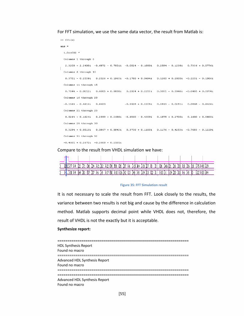
For FFT simulation, we use the same data vector, the result from Matlab is:
Compare to the result from VHDL simulation we have:
Figure 35: FFT Simulation result
It is not necessary to scale the result from FFT. Look closely to the results, the
variance between two results is not big and cause by the difference in calculation
method. Matlab supports decimal point while VHDL does not, therefore, the
result of VHDL is not the exactly but it is acceptable.
Synthesize report:
================================================================== HDL Synthesis Report Found no macro ================================================================== Advanced HDL Synthesis Report Found no macro ================================================================== ================================================================== Advanced HDL Synthesis Report Found no macro

[56]
==================================================================
Timing Summary: ‐‐‐‐‐‐‐‐‐‐‐‐‐‐‐ Speed Grade: ‐7 Minimum period: 7.951ns (Maximum Frequency: 125.778MHz) Minimum input arrival time before clock: 4.866ns Maximum output required time after clock: 4.850ns Maximum combinational path delay: No path found ==================================================================
4.7 Viterbi
Figure 36: Viterbi Block
The Viterbi Decoder is provided by Xilinx as a temporary license, it means that it
only work for a certain amount of time when implemented on Hardware. But it
still works in simulation.
For the set up, I use the standard Viterbi Type with constraint length of 7 and
trace back length of 42. This Viterbi has the best state option and Hard Coding.
The Convolution code is 1111001 and 1011011 binary which is 171 and 133 in
octal format. To test the Viterbi decoder, we run the simulation which have the
input is the output of the convolution coding, the result is expected to be the
original data as we see in the Convolution Encoder section:
Input value:
h’ 0 3 2 1 1 0 2 3 3 3 0 3 2 3 2 0 0 2 1 2 0 3 0 3 3 0 1 0 0 2 0 1 0 0 2 1 3 3
3 1 0 2 2 1 0 3 1 1 2 3 1 1

[57]
Output:
Figure 37: Viterbi Simulation result
Compare to the input in the convolution encoder, the two are almost identical
with a difference of one bit.
Synthesize report:
================================================================== HDL Synthesis Report Found no macro ================================================================== Advanced HDL Synthesis Report Found no macro ================================================================== ================================================================== Advanced HDL Synthesis Report Found no macro ================================================================== Timing Summary:
‐‐‐‐‐‐‐‐‐‐‐‐‐‐‐ Speed Grade: ‐7 Minimum period: 6.092ns (Maximum Frequency: 164.160MHz) Minimum input arrival time before clock: 1.418ns Maximum output required time after clock: 3.900ns Maximum combinational path delay: No path found ===================================================================
4.8 System Simulation Result
After verified all the block functionality, we run the simulation as a whole. In the
simulation between Transmitter and receiver, there is a channel block which
adds noise and channel estimator. The whole system simulation wave from is:

[58]
Figure 38: System simulation
Zoom into input:
Figure 39: Input data
[59]
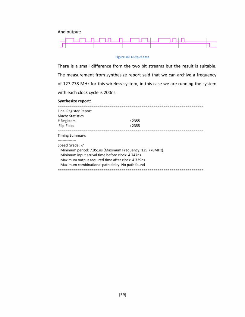
And output:
Figure 40: Output data
There is a small difference from the two bit streams but the result is suitable.
The measurement from synthesize report said that we can archive a frequency
of 127.778 MHz for this wireless system, in this case we are running the system
with each clock cycle is 200ns.
Synthesize report: ========================================================================= Final Register Report Macro Statistics # Registers : 2355 Flip‐Flops : 2355 ========================================================================= Timing Summary: ‐‐‐‐‐‐‐‐‐‐‐‐‐‐‐ Speed Grade: ‐7 Minimum period: 7.951ns (Maximum Frequency: 125.778MHz) Minimum input arrival time before clock: 4.747ns Maximum output required time after clock: 4.339ns Maximum combinational path delay: No path found =========================================================================

[60]
Chapter 5: Conclusion and Recommendations
In the conclusion, I have verified the functionality of the wiressless
communication system which was build based on the 802.11n draft. The result
from Matlab simulation showed that the 802.11n system can provided a good
performance and data rate as describe in section 1.5. It is more resistance to
inference, noise and latency caused by environment. 802.11n also has the
backward compability which 802.11a/b/g. The main advantage is 802.11n is a
MIMO system, it can be configure to have as much antenna as possible, the
requirement is that the antennas have to be placed a distant of half‐wave length
apart to ensure them working properly. This project is a 2x2 MIMO system,
which mean the system can transmit and received multiple signals at the same
instant time to increase the data rate and overall performance.
For the implementation of the wireless system in VHDL, the simulation result
showed the wireless system is successful design for FPGA. However, the
implementation on hardware could not be finished due to some difficulty on the
COREgenerator. The Viterbi decoder that we used for our design does not have
the license. I have acquired a temporary license from Xilinx for the Viterbi
decoder, but it only allows simulating. There is an error that prevents the
implementation on hardware. The error comes from Xilinx COREgenerator.
Therefore, at the end, I do not have the result on hardware.
On the other hand, during the design, there are a few notice came up when
using the COREgenerator to create a block such as Fast Fourier Transform. I
decided to use the block which provided by Xinlinx since it would save more time
rather than build a brand new Fast Fourier Transform from blank space. There
are some disadvantage when using this block, 802.11n require a system with 64
subcarrier, but the FFT block only support the used of 32 data block. The data
block will need to be divided into two smaller blocks, since each block is format
with header and some other bit to create and channel, the real data in each
block will be less than expected. It will decrease the data rate and performance

[61]
of 802.11n in FPGA implementation. The other disadvantage due to its structure,
the FFT block is constantly running even without any input data and start signal.
To keep the block at idle state, a reset signal will need to be input every 48 clock
cycles. An interrupt handler is needed to ensure the block function normally. The
second problem is the Viterbi block, it is require a quite amount of time to
product the result since each calculation require a clock cycle, to boot up the
performance, the Viterbi should be operate in a faster clock than the whole
system. Viterbi decoder block is only accurate with the large amount of data, if
the data is less than ten the output will be inaccurate or just zero. The last
problem which I encounter for this project is the limited resource that the FPGA.
Because the design require a big amount of calculation for the FFT, Alamouti
Decoder and Channel, even that I have tried to minimize the calculation as much
as possible, the outcome still consume more than one hundred percent resource
of the Virtex II‐Pro board.
I would recommend the future project to use the Virtex 5 instead of Virtex II or
Virtex 4. Virtex 5 also supports floating point calculation which will give a more
precise result. COREgenerator also has another FFT block, this block is more
basic, it will required a lot of configuration, especially in the scale data output.
This block will support the 64 carrier calculation which satisfy 802.11n
requirement. At the end, FPGA is a feasible solution to implement wireless
communication system, but it also contains some disadvantage than the normal
micro controller method such as resource limitation and accuracy in calculation.
With the development of technology, FPGA can overcome these difficulties in
the near future and become the alternative solution for digital signal processing
solution.

[62]
Bibliography 1. INTINI, ANÍBAL LUIS. Orthogonal Frequency Division Multiplexing for Wireless Networks. SANTA BARBARA : UNIVERSITY OF CALIFORNIA SANTA BARBARA, 2000. Graduate thesis.
2. Wireless LANs. [Online] [Cited: March 29, 2009.] http://www.wirelesslans.org/.
3. Razzouk, Tayseer, et al. Hardware Simulation for Future WLAN Standard 802.11n. 2006.
4. Mitchell, Bradley. Wireless Standards ‐ 802.11b 802.11a 802.11g and 802.11n. About.com: Wireless/Networking. [Online] [Cited: March 31, 2009.] http://compnetworking.about.com/cs/wireless80211/a/aa80211standard.htm.
5. VAN NEE, RICHARD, et al. The 802.11n MIMO‐OFDM Standard forWireless LAN and Beyond. s.l. : Springer, 2006.
6. Langton, Charan. Orthogonal Frequency Divison Multiplexing (OFDM) Tutorial. s.l. : www.complextoreal.com, 2002.
7. Alamouti, Siavash M. Simple Transmit Diversity Technique for Wireless Communication . s.l. : IEEE Journal, 1998. Journal.
8. Wain, Richard, et al. An overview of FPGAs and FPGA programming; Initial experiences at Daresbury`. Cheshire : Computational Science and Engineering Department, CCLRC Daresbury Laborator, 2006.
9. Han, Yunghsiang S. Introduction to Binary Convolutional Codes. Taipei : National Taipei University.
10. Convolution Encoder v6.1. s.l. : Xilinx, 2007.

[63]
Appendix
I. Matlab Simulation Code:
Interleaver
function y = interleaver(x, Block_Size, N_BPSC, I_DEPTH, D) k = 0:Block_Size-1; s = max(N_BPSC/2, 1); i = (Block_Size/I_DEPTH)*mod(k, I_DEPTH) + floor(k/I_DEPTH); j = s*floor(i/s) + mod( i+Block_Size-floor(I_DEPTH*i/Block_Size) , s); output_index = mod( j+Block_Size-N_BPSC*D , Block_Size) NUM_of_CYCLE = length(x) / Block_Size; for cycle = 0:NUM_of_CYCLE-1; temp(1:Block_Size) = x(cycle*Block_Size+1 : (cycle+1)*Block_Size); for index = 1:Block_Size; temp_intrlv(index) = temp(output_index(index)+1); end y(cycle*Block_Size+1 : (cycle+1)*Block_Size) = temp_intrlv(1:Block_Size); end end Deinterleaver
function y = Deinterleaver(x, Block_Size, N_BPSC, I_DEPTH, D) k = 0:Block_Size-1; s = max(N_BPSC/2, 1); i = (Block_Size/I_DEPTH)*mod(k, I_DEPTH) + floor(k/I_DEPTH); j = s*floor(i/s) + mod( i+Block_Size-floor(I_DEPTH*i/Block_Size) , s); output_index = mod( j+Block_Size-N_BPSC*D , Block_Size); NUM_of_CYCLE = length(x) / Block_Size; for cycle = 0:NUM_of_CYCLE-1; temp(1: Block_Size) = x(cycle*Block_Size+1 : (cycle+1)*Block_Size); for index = 1:Block_Size; temp_deintrlv(output_index(index)+1) = temp(index); end y(cycle*Block_Size+1: (cycle+1)*Block_Size) = temp_deintrlv(1:Block_Size); end end
QAM Mapping
function y = mapping(x) if (x(1)==0) && (x(2)==0) && (x(3)==0) && (x(4)==0)
[64]
y = -3 - 3*i; elseif (x(1)==0) && (x(2)==0) && (x(3)==0) && (x(4)==1) y = -3 - 1*i; elseif (x(1)==0) && (x(2)==0) && (x(3)==1) && (x(4)==0) y = -3 + 3*i; elseif (x(1)==0) && (x(2)==0) && (x(3)==1) && (x(4)==1) y = -3 + 1*i; elseif (x(1)==0) && (x(2)==1) && (x(3)==0) && (x(4)==0) y = -1 - 3*i; elseif (x(1)==0) && (x(2)==1) && (x(3)==0) && (x(4)==1) y = -1 - 1*i; elseif (x(1)==0) && (x(2)==1) && (x(3)==1) && (x(4)==0) y = -1 + 3*i; elseif (x(1)==0) && (x(2)==1) && (x(3)==1) && (x(4)==1) y = -1 + 1*i; elseif (x(1)==1) && (x(2)==0) && (x(3)==0) && (x(4)==0) y = 3 - 3*i; elseif (x(1)==1) && (x(2)==0) && (x(3)==0) && (x(4)==1) y = 3 - 1*i; elseif (x(1)==1) && (x(2)==0) && (x(3)==1) && (x(4)==0) y = 3 + 3*i; elseif (x(1)==1) && (x(2)==0) && (x(3)==1) && (x(4)==1) y = 3 + 1*i; elseif (x(1)==1) && (x(2)==1) && (x(3)==0) && (x(4)==0) y = 1 - 3*i; elseif (x(1)==1) && (x(2)==1) && (x(3)==0) && (x(4)==1) y = 1 - 1*i; elseif (x(1)==1) && (x(2)==1) && (x(3)==1) && (x(4)==0) y = 1 + 3*i; elseif (x(1)==1) && (x(2)==1) && (x(3)==1) && (x(4)==1) y = 1 + 1*i; end end
D‐QAM
function x = demap(y) if y == -3 + 3*i x(1)=0; x(2)=0; x(3)=1; x(4)=0; elseif y == -3 + 1*i x(1)=0; x(2)=0; x(3)=1; x(4)=1; elseif y == -3 - 3*i x(1)=0; x(2)=0; x(3)=0; x(4)=0; elseif y == -3 - 1*i x(1)=0; x(2)=0;

[65]
x(3)=0; x(4)=1; elseif y == -1 + 3*i x(1)=0; x(2)=1; x(3)=1; x(4)=0; elseif y == -1 + 1*i x(1)=0; x(2)=1; x(3)=1; x(4)=1; elseif y == -1 - 3*i x(1)=0; x(2)=1; x(3)=0; x(4)=0; elseif y == -1 - 1*i x(1)=0; x(2)=1; x(3)=0; x(4)=1; elseif y == 3 + 3*i x(1)=0; x(2)=1; x(3)=0; x(4)=1; elseif y == 3 + 1*i x(1)=1; x(2)=0; x(3)=1; x(4)=1; elseif y == 3 - 3*i x(1)=1; x(2)=0; x(3)=0; x(4)=0; elseif y == 3 - 1*i x(1)=1; x(2)=0; x(3)=0; x(4)=1; elseif y == 1 + 3*i x(1)=1; x(2)=1; x(3)=1; x(4)=0; elseif y == 1 + 1*i x(1)=1; x(2)=1; x(3)=1; x(4)=1; elseif y == 1 - 3*i x(1)=1; x(2)=1; x(3)=0; x(4)=0;

[66]
elseif y == 1 - 1*i x(1)=1; x(2)=1; x(3)=0; x(4)=1; end end
802.11n Simulation
clear all; clc; % Define parameter Blocksize = 52; Idepth = 13; h0 = 1; h1 = 1; h2 = 1; h3 = 1; n0 = 0; n1 = 0; n2 = 0; n3 = 0; %Convolution code t = poly2trellis([7],[171 133]); d = [0 1 0 0 0 0 1 0 0 1 1 0 0 0 0 1 0 1 1 0 0 0 1 1 0 1]; c = convenc(d,t); %Interleaver d_intlr = interleaver(c, Blocksize, 1, Idepth, 0); %16QAM d_qam = zeros(1,14); a = 1; for i = 1: Idepth d_qam(i)= mapping(d_intlr(a:a+3)); a = a+4; end %Alamouti Encoder s = d_qam; s0 = ones(1,length(s)); s1 = ones(1,length(s)); temp = ones(1:2); r0 = zeros(1,(length(s)/2)); r1 = zeros(1,(length(s)/2)); r2 = zeros(1,(length(s)/2)); r3 = zeros(1,(length(s)/2)); a = 1;

[67]
b = 1; for i=1:length(s) if a == 1 temp(1) = s(i); a = a+1; elseif a == 2 temp(2) = s(i); a = 1; s0(b) = temp(1); s1(b) = temp(2); s0(b+1) = -conj(temp(2)); s1(b+1) = conj(temp(1)); b = b+2; end end %IFFT s0_ifft = 32*ifft(s0); s1_ifft = 32*ifft(s1); %Channel a = 1; b = 1; for i=1:length(s) if a==1 r0(b) = h0*s0_ifft(i) + h1*s1_ifft(i) + n0; r2(b) = h2*s0_ifft(i) + h3*s1_ifft(i) + n2; a = a+1; elseif a==2 r1(b) = h0*s0_ifft(i) + h1*s1_ifft(i) + n1; r3(b) = h2*s0_ifft(i) + h3*s1_ifft(i) + n3; a = 1; b = b+1; end end c0 = zeros(1, length(s)); c1 = zeros(1, length(s)); a = 1; b = 1; for i=1:length(s) if a==1 c0(i) = r0(b); c1(i) = r2(b); a = a+1; elseif a==2 c0(i) = r1(b); c1(i) = r3(b); a = 1; b = b+1; end end %FFT c0_fft = fft(c0)/32; c1_fft = fft(c1)/32;

[68]
%Alamouti Decoder s00 = zeros(1, length(s)/2); s11 = zeros(1, length(s)/2); a = 1; for i=1:length(s)/2 s00(i) = conj(h0)*c0_fft(a) + h1*conj(c0_fft(a+1)) + conj(h2)*c1_fft(a) + h3*conj(c1_fft(a+1)); s11(i) = conj(h1)*c0_fft(a) - h0*conj(c0_fft(a+1)) + conj(h3)*c1_fft(a) - h2*conj(c1_fft(a+1)); a = a+2; end s_out = ones(1,length(s)); a = 1; b = 1; for i=1:length(s) if a == 1 s_out(i) = s00(b); a = a + 1; elseif a == 2 s_out(i) = s11(b); a = 1; b = b + 1; end end s_out = s_out/4; %D-QAM d_D-QAM = zeros(1,52); a = 1; for i = 1: Idepth d_D-QAM(a:a+3) = demap(round(s_out(i))); a = a+4; end %Deinterleaver d_dintlr = Deinterleaver(d_D-QAM, Blocksize, 1, Idepth, 0); tb = 2; %Viterbi Decoder deco = vitdec(d_dintlr,t,tb,'trunc', 'hard');
OFDM example
%this is a simple exam code for OFDM modulation and demodulation %source data clear all close all SNR = [1:2:30]; snr = 10.^(SNR/10);

[69]
BER = zeros(1, length(snr)); for l = 1:length(snr) n = 2^16; %bits M = 16; %QAM modulation x = randint(1,n,M); c = 64; %subcarrier dB = 20; %AWGN SNR %convert the sequential data into parallel form x_vec = reshape(x,c,n/c); xqam = modem.qammod(M); %apply 16-QAM modulation x_mod = modulate(xqam,x_vec); %take IFFT of each subcarrier x_ifft = ifft(x_mod); % scatterplot(x_mod(1,:)); % scatterplot(x_ifft(1,:)); %without noise %y = x_ifft; %transmit signal through AWGN channel y = awgn(x_ifft,SNR(l),'measured'); %take FFT of each subcarrier y_fft = fft(y); %plot the received signal vector in subarrier no. 1 % scatterplot(y_fft(1,:)); %demodulate to recover the transmit signal y_vec = demodulate(modem.qamdemod(M),y_fft); % scatterplot(y_vec(1,:)); %recombine it into a seqeuential data y_seq = reshape(y_vec,1,n); %check symbol error rate [num1,ser]= symerr(x_vec,y_vec) %check bit error rate [num2,BER(l)]= biterr(x,y_seq,10) end semilogy(SNR,BER) xlabel('SNR [dB]')

[70]
ylabel('BER') axis([0 SNR(length(SNR)) 1e-5 .5]) grid on II. VHDL code
Convolution:
library IEEE; use IEEE.STD_LOGIC_1164.ALL; use IEEE.STD_LOGIC_ARITH.ALL; use IEEE.STD_LOGIC_UNSIGNED.ALL; entity Convolution_top is port ( data_in: IN std_logic; data_out_v: OUT std_logic_VECTOR(1 downto 0); nd: IN std_logic; rdy: OUT std_logic; ce: IN std_logic; sclr: IN std_logic; aclr: IN std_logic; clk: IN std_logic); end Convolution_top; architecture Behavioral of Convolution_top is component Convolution port ( data_in: IN std_logic; data_out_v: OUT std_logic_VECTOR(1 downto 0); nd: IN std_logic; rdy: OUT std_logic; ce: IN std_logic; sclr: IN std_logic; aclr: IN std_logic; clk: IN std_logic); end component; begin C : Convolution port map (data_in, data_out_v, nd, rdy, ce, sclr, aclr, clk); end Behavioral;
Modify data out of Convolution
library IEEE; use IEEE.STD_LOGIC_1164.ALL; use IEEE.STD_LOGIC_ARITH.ALL; use IEEE.STD_LOGIC_UNSIGNED.ALL;

[71]
entity out_convo is port ( clk : in std_logic; nd : in std_logic; data_in : in std_logic_vector(1 downto 0); data_out : out std_logic_vector(51 downto 0); reset : in std_logic; rdy : out std_logic); end out_convo; architecture Behavioral of out_convo is begin process(clk, reset) variable a : integer := 0; variable dout : std_logic_vector( 51 downto 0); begin if reset = '1' then dout := (others => '0'); rdy <= '0'; elsif rising_edge(clk) then if nd = '1' and a < 50 then dout(a+1 downto a) := data_in; a := a+2; rdy <= '0'; elsif nd = '0' and a <51 and a>0 then dout(51 downto a) := (others => '0'); a := 0; rdy <= '1'; elsif a = 50 then dout(51 downto 50) := data_in; a := 0; rdy <= '1'; elsif nd = '0' and a = 0 then dout := (others => '0'); rdy <= '0'; else dout := dout; rdy <= '0'; end if; end if; data_out <= dout; end process; end Behavioral;
Interleaver:

[72]
library IEEE; use IEEE.STD_LOGIC_1164.ALL; use IEEE.STD_LOGIC_ARITH.ALL; use IEEE.STD_LOGIC_UNSIGNED.ALL; entity InDo is port ( clk, reset : in std_logic; nd : in std_logic; rdy : out std_logic; x : in std_logic_vector(1 to 52); y : out std_logic_vector(1 to 52) := (others => '0')); end InDo; architecture Behavioral of InDo is type out_index is array(1 to 52) of integer; signal outindex : out_index; signal c : std_logic_vector(1 to 52); signal rd : std_logic; begin outindex(1)<=16; outindex(27)<=18; outindex(2)<=21; outindex(28)<=23; outindex(3)<=24; outindex(29)<=26; outindex(4)<=29; outindex(30)<=31; outindex(5)<=32; outindex(31)<=34; outindex(6)<=37; outindex(32)<=39; outindex(7)<=40; outindex(33)<=42; outindex(8)<=45; outindex(34)<=47; outindex(9)<=48; outindex(35)<=50; outindex(10)<=1; outindex(36)<=3; outindex(11)<=4; outindex(37)<=6; outindex(12)<=9; outindex(38)<=11; outindex(13)<=12; outindex(39)<=14; outindex(14)<=17; outindex(40)<=19; outindex(15)<=20; outindex(41)<=22; outindex(16)<=25; outindex(42)<=27; outindex(17)<=28; outindex(43)<=30; outindex(18)<=33; outindex(44)<=35; outindex(19)<=36; outindex(45)<=38; outindex(20)<=41; outindex(46)<=43; outindex(21)<=44; outindex(47)<=46; outindex(22)<=49; outindex(48)<=51; outindex(23)<=0; outindex(49)<=2; outindex(24)<=5; outindex(50)<=7; outindex(25)<=8; outindex(51)<=10; outindex(26)<=13; outindex(52)<=15; process(reset, clk) variable a : integer;

[73]
begin if reset = '1' then y<= (others => '0'); rd <= '0'; elsif rising_Edge(clk) then if nd = '1' then for i in 1 to 52 loop c(i) <= x(outindex(i)+1); a := i; if i = 52 then rd <= '1'; end if; end loop; elsif a = 52 then rd <= '0'; end if; y <= c; end if; rdy <= rd; end process; end Behavioral;
Top level of Convolution and Interleaver
library IEEE; use IEEE.STD_LOGIC_1164.ALL; use IEEE.STD_LOGIC_ARITH.ALL; use IEEE.STD_LOGIC_UNSIGNED.ALL; entity Convolution_to_interleaver is port ( data_in : in std_logic; reset : in std_logic; nd : in std_logic; clk : in std_logic; data_out : out std_logic_Vector(51 downto 0); rdy : out std_logic); end Convolution_to_interleaver; architecture Behavioral of Convolution_to_interleaver is component Convolution_top is port ( data_in: IN std_logic; data_out_v: OUT std_logic_VECTOR(1 downto 0); nd: IN std_logic; rdy: OUT std_logic; ce: IN std_logic;
[74]
sclr: IN std_logic; aclr: IN std_logic; clk: IN std_logic); end component Convolution_top; component InDo is port ( clk, reset : in std_logic; nd : in std_logic; rdy : out std_logic; x : in std_logic_vector(1 to 52); y : out std_logic_vector(1 to 52) := (others => '0')); end component InDo; component out_convo is port ( clk : in std_logic; nd : in std_logic; data_in : in std_logic_vector(1 downto 0); data_out : out std_logic_vector(51 downto 0); reset : in std_logic; rdy : out std_logic); end component out_convo; signal data_convolution : std_logic_vector(1 downto 0); signal rdy_convolution : std_logic; signal data_to_interleaver : std_logic_vector(51 downto 0); signal rdy_to_interleaver : std_logic; begin C : Convolution_top port map (data_in, data_convolution, nd, rdy_convolution, '1', reset, reset, clk); O : out_convo port map (clk, rdy_convolution, data_convolution, data_to_interleaver, reset, rdy_to_interleaver); I : InDo port map (clk, reset, rdy_to_interleaver, rdy, data_to_interleaver, data_out); end Behavioral;
Modify data to QAM
library IEEE; use IEEE.STD_LOGIC_1164.ALL; use IEEE.STD_LOGIC_ARITH.ALL; use IEEE.STD_LOGIC_UNSIGNED.ALL; entity to_qam is port ( clk, reset : in std_logic; d_in : in std_logic_vector(51 downto 0);

[75]
d_out : out std_logic_vector(3 downto 0); nd : in std_logic; rdy : out std_logic); end to_qam; architecture Behavioral of to_qam is constant zero : std_logic_vector(55 downto 0) := (others => '0'); begin process(clk, reset, nd) variable temp1 : std_logic_Vector(55 downto 0); variable temp2 : std_logic_Vector(55 downto 0); variable temp : std_logic_Vector(55 downto 0); variable busy : std_logic := '0'; variable a : integer := 100; begin if reset = '1' then rdy <= '0'; d_out <= "0000"; temp1 := zero; temp2 := zero; elsif nd = '1' then if busy = '0' then temp1 := "0000"&d_in; a := 0; elsif busy = '1' then temp2 := "0000"&d_in; end if; elsif rising_edge(clk) then if a<55 then ‐‐temp := temp1; d_out <= temp1(a+3 downto a); rdy <= '1'; busy := '1'; a := a+4; elsif a>55 and temp2 /= zero then temp1 := temp2; a := 0; temp2 := zero; rdy <= '0'; elsif a>55 and temp2 = zero then temp1 := zero; a := 100; busy := '0'; rdy <= '0'; else rdy <= '0'; d_out <= "0000"; end if; end if;

[76]
end process; end Behavioral;
QAM
library IEEE; use IEEE.STD_LOGIC_1164.ALL; use IEEE.STD_LOGIC_ARITH.ALL; use IEEE.STD_LOGIC_UNSIGNED.ALL; entity qam_16 is port ( clk : in std_logic; reset: in std_logic; nd : in std_logic; rdy : out std_logic; Iout : out std_logic_vector(3 downto 0); Qout : out std_logic_vector(3 downto 0); d_in : in std_logic_vector(3 downto 0)); end qam_16; architecture Behavioral of qam_16 is component mux is port ( i_in : in std_logic_vector(1 downto 0); o_out : out std_logic_vector(3 downto 0)); end component mux; signal I_out : std_logic_vector(1 downto 0); signal Q_out : std_logic_vector(1 downto 0); begin process (clk, reset) constant p_one : std_logic_vector(1 downto 0) := "11"; constant n_one : std_logic_vector(1 downto 0) := "01"; constant p_three : std_logic_vector(1 downto 0) := "10"; constant n_three : std_logic_vector(1 downto 0) := "00"; begin if reset = '1' then I_out <= ( others => '0'); Q_out <= ( others => '0'); elsif clk' event and clk = '1' then if nd = '1' then rdy <= '1'; elsif nd = '0' then rdy <= '0'; end if; case d_in is

[77]
when "0000" => I_out <= n_three; Q_out <= n_three; when "0001" => I_out <= n_three; Q_out <= n_one; when "0010" => I_out <= n_three; Q_out <= p_three; when "0011" => I_out <= n_three; Q_out <= p_one; when "0100" => I_out <= n_one; Q_out <= n_three; when "0101" => I_out <= n_one; Q_out <= n_one; when "0110" => I_out <= n_one; Q_out <= p_three; when "0111" => I_out <= n_one; Q_out <= p_one; when "1000" => I_out <= p_three; Q_out <= n_three; when "1001" => I_out <= p_three; Q_out <= n_one; when "1010" => I_out <= p_three; Q_out <= p_three; when "1011" => I_out <= p_three; Q_out <= p_one; when "1100" => I_out <= p_one; Q_out <= n_three; when "1101" => I_out <= p_one; Q_out <= n_one; when "1110" => I_out <= p_one; Q_out <= p_three; when "1111" => I_out <= p_one; Q_out <= p_one;
[78]
when others => I_out <= "‐‐"; I_out <= "‐‐"; end case; end if; end process; M1 : mux port map (I_out, Iout); M2 : mux port map (Q_out, Qout); end Behavioral;
Convolution and Interleaver and QAM top level:
library IEEE; use IEEE.STD_LOGIC_1164.ALL; use IEEE.STD_LOGIC_ARITH.ALL; use IEEE.STD_LOGIC_UNSIGNED.ALL; entity Convolution_to_interleaver_to_qam is port ( reset, clk : in std_logic; d_in : in std_logic; nd : in std_logic; d_inter : out std_logic_vector(51 downto 0); rd_inter : out std_logic; data_qam_I : out std_logic_vector(3 downto 0); data_qam_Q : out std_logic_vector(3 downto 0); qam_rdy : out std_logic; d_out : out std_logic_vector(3 downto 0); rdy : out std_logic); end Convolution_to_interleaver_to_qam; architecture Behavioral of Convolution_to_interleaver_to_qam is component Convolution_to_interleaver is port ( data_in : in std_logic; reset : in std_logic; nd : in std_logic; clk : in std_logic; data_out : out std_logic_Vector(51 downto 0); rdy : out std_logic); end component Convolution_to_interleaver; component to_qam is port ( clk, reset : in std_logic; d_in : in std_logic_vector(51 downto 0); d_out : out std_logic_vector(3 downto 0);
[79]
nd : in std_logic; rdy : out std_logic); end component to_qam; component qam_16 is port ( clk : in std_logic; reset: in std_logic; nd : in std_logic; rdy : out std_logic; Iout : out std_logic_vector(3 downto 0); Qout : out std_logic_vector(3 downto 0); d_in : in std_logic_vector(3 downto 0)); end component qam_16; signal temp_d : std_logic_vector(51 downto 0); signal rd, rd1 : std_logic; signal temp : std_logic_vector(3 downto 0); begin C : Convolution_to_interleaver port map (d_in, reset, nd, clk, temp_d, rd); TQ : to_qam port map (clk, reset, temp_d, temp, rd, rd1); Q : qam_16 port map (clk, reset, rd1, qam_rdy, data_qam_I, data_qam_Q, temp); d_inter <= temp_d; rd_inter <= rd; d_out <= temp; rdy <= rd1; end Behavioral;
Alamouti Encoder:
library IEEE; use IEEE.STD_LOGIC_1164.ALL; use IEEE.STD_LOGIC_ARITH.ALL; use IEEE.STD_LOGIC_UNSIGNED.ALL; use ieee.numeric_std.all; entity alamouti_encoder is port ( clk, reset : in std_logic; nd : in std_logic; rdy : out std_logic; d_I : in std_logic_vector(3 downto 0); d_Q : in std_logic_vector(3 downto 0); dI0, dI1 : out std_logic_vector(3 downto 0); dQ0, dQ1 : out std_logic_vector(3 downto 0)); end alamouti_encoder; architecture Behavioral of alamouti_encoder is

[80]
type IQ is array(0 to 1) of integer; signal tempI, tempQ : IQ; signal rdy_data : std_logic; begin process (clk, reset) variable I, Q : IQ; variable a : integer := 0; begin if reset = '1' then rdy_data <= '0'; elsif rising_edge(clk) then if nd = '1' then if a = 0 then I(a) := conv_integer(d_I); Q(a) := conv_integer(d_Q); a := a+1; rdy_data <= '0'; elsif a = 1 then I(a) := conv_integer(d_I); Q(a) := conv_integer(d_Q); a := 0; rdy_data <= '1'; else rdy_data <= '0'; end if; else rdy_data <= '0'; end if; tempI <= I; tempQ <= Q; end if; end process; process (clk) variable II, QQ : IQ; variable a : integer := 100; begin if reset = '1' then dI0 <= (others => '0'); dI1 <= (others => '0'); dQ0 <= (others => '0'); dQ1 <= (others => '0'); elsif rising_edge(clk) then if rdy_data = '1' then II := tempI; QQ := tempQ; a := 0;

[81]
end if; if a = 0 then rdy <= '1'; dI0 <= conv_std_logic_vector(conv_signed(II(0),4),4); dQ0 <= conv_std_logic_vector(conv_signed(QQ(0),4),4); dI1 <= conv_std_logic_vector(conv_signed(II(1),4),4); dQ1 <= conv_std_logic_vector(conv_signed(QQ(1),4),4); a := a + 1; elsif a = 1 then rdy <= '1'; dI0 <= conv_std_logic_vector(conv_signed(0 ‐ II(1),4),4); dQ0 <= conv_std_logic_vector(conv_signed(QQ(1),4),4); dI1 <= conv_std_logic_vector(conv_signed(II(0),4),4); dQ1 <= conv_std_logic_vector(conv_signed(0 ‐ QQ(0),4),4); a := 110; else rdy <= '0'; end if; end if; end process; end Behavioral;
Transmitter and MIMO without IFFT:
library IEEE; use IEEE.STD_LOGIC_1164.ALL; use IEEE.STD_LOGIC_ARITH.ALL; use IEEE.STD_LOGIC_UNSIGNED.ALL; entity convolution_to_qam_MIMO is port ( clk, reset : in std_logic; d_in : in std_logic; nd : in std_logic; d_I, d_Q : out std_logic_vector(3 downto 0); qrdy : out std_logic; rdy : out std_logic; sI0, sQ0 : out std_logic_vector(3 downto 0); sI1, sQ1 : out std_logic_vector(3 downto 0)); end convolution_to_qam_MIMO; architecture Behavioral of convolution_to_qam_MIMO is component Convolution_to_interleaver_to_qam is port ( reset, clk : in std_logic; d_in : in std_logic; nd : in std_logic;

[82]
d_inter : out std_logic_vector(51 downto 0); rd_inter : out std_logic; data_qam_I : out std_logic_vector(3 downto 0); data_qam_Q : out std_logic_vector(3 downto 0); qam_rdy : out std_logic; d_out : out std_logic_vector(3 downto 0); rdy : out std_logic); end component Convolution_to_interleaver_to_qam; component alamouti_encoder is port ( clk, reset : in std_logic; nd : in std_logic; rdy : out std_logic; d_I : in std_logic_vector(3 downto 0); d_Q : in std_logic_vector(3 downto 0); dI0, dI1 : out std_logic_vector(3 downto 0); dQ0, dQ1 : out std_logic_vector(3 downto 0)); end component alamouti_encoder; signal qam_rdy : std_logic; signal I, Q : std_logic_vector(3 downto 0); begin C : Convolution_to_interleaver_to_qam port map (reset, clk, d_in, nd, open, open, I, Q, qam_rdy, open, open); A : alamouti_encoder port map (clk, reset, qam_rdy, rdy, I, Q, sI0, sI1, sQ0, sQ1); d_I <= I; d_Q <= Q; qrdy <= qam_rdy; end Behavioral;
Random number generator
library IEEE; use IEEE.STD_LOGIC_1164.ALL; use IEEE.STD_LOGIC_ARITH.ALL; use IEEE.STD_LOGIC_UNSIGNED.ALL; entity random_number is port ( d_in : in std_logic_vector(7 downto 0); clk, reset : in std_logic; start : in std_logic; rdy : out std_logic; d_out : out std_logic); end random_number;

[83]
architecture Behavioral of random_number is begin process (clk, reset) variable i : integer := 0; variable d : std_logic; variable temp : std_logic_vector(7 downto 0); begin if reset = '1' then rdy <= '0'; d_out <= '0'; d := '0'; i := 0; elsif rising_edge(clk) then if start = '1' then temp := d_in; i := i+1; rdy <= '0'; elsif i>0 and i<=50 then d := (temp(4) xor temp(7)) xor temp(5); temp(7 downto 0) := temp (6 downto 0) & d; rdy <= '1'; i := i + 1; elsif i > 50 then rdy <= '0'; i := 0; else rdy <= '0'; end if; end if; d_out <= d; end process; end Behavioral;
IFFT_control signal
library IEEE; use IEEE.STD_LOGIC_1164.ALL; use IEEE.STD_LOGIC_ARITH.ALL; use IEEE.STD_LOGIC_UNSIGNED.ALL; entity ifft_control is port ( clk, reset : in std_logic; nd : in std_logic; d_I_in : in std_logic_vector(3 downto 0); d_Q_in : in std_logic_vector(3 downto 0); start : out std_logic;

[84]
rdy : out std_logic; mwr : out std_logic; d_I_out : out std_logic_vector(8 downto 0); d_Q_out : out std_logic_vector(8 downto 0)); end ifft_control; architecture Behavioral of ifft_control is type memory is array(1 to 32) of std_logic_vector(8 downto 0); signal temp_I : memory; signal temp_Q : memory; constant zero : std_logic_vector(8 downto 0) := (others => '0'); signal rdy_data : std_logic; signal tempm : std_logic; signal start1 : std_logic; begin process(reset, clk, tempm) variable a : integer := 0; begin if reset = '1' then start1 <= '0'; elsif rising_edge(clk) then if tempm = '1' then a := 1; start1 <= '0'; elsif a>=1 and a <33 then a := a+1; start1 <= '0'; elsif a = 33 then start1 <= '1'; a := 0; else start1 <= '0'; end if; end if; end process; process (reset, clk, start1) variable a : integer := 0; begin if reset = '1' then start <= '0'; elsif rising_edge(clk) then if start1 = '1' then a := a+1; if a < 1 then start <= '0';

[85]
elsif a = 1 then start <= start1; a := 0; else start <= '0'; end if; else start <= '0'; end if; end if; end process; process(clk, reset) variable a : integer := 1; begin if reset = '1' then tempm <= '0'; rdy_data <= '0'; for i in 1 to 32 loop temp_I(i) <= zero; temp_Q(i) <= zero; end loop; elsif rising_edge(clk) then if nd = '1' and a < 28 then temp_I(a)(3 downto 0) <= d_I_in; temp_Q(a)(3 downto 0) <= d_Q_in; a := a+1; rdy_data <= '0'; tempm <= '0'; elsif a = 28 then temp_I(a)(3 downto 0) <= d_I_in; temp_Q(a)(3 downto 0) <= d_Q_in; a := a+1; tempm <= '1'; elsif a = 29 then tempm <= '0'; rdy_data <= '1'; a := 1; else rdy_data <= '0'; tempm <= '0'; end if; mwr <= tempm; rdy <= rdy_data; end if; end process; process (reset, clk, rdy_data) variable b : integer := 100; variable wa : std_logic := '0'; begin

[86]
if reset = '1' then d_I_out <= zero; d_Q_out <= zero; elsif rising_edge(clk) then if rdy_data = '1' and b = 100 then b := 1; elsif rdy_data = '1' and b/=100 then wa := '1'; end if; if b < 33 then d_I_out <= temp_I(b); d_Q_out <= temp_Q(b); b := b+1; elsif b = 33 and wa = '1' then b := 1; elsif b = 33 and wa = '0' then b := 100; end if; end if; end process; end Behavioral;
Feeding block for done and mrd signal
library IEEE; use IEEE.STD_LOGIC_1164.ALL; use IEEE.STD_LOGIC_ARITH.ALL; use IEEE.STD_LOGIC_UNSIGNED.ALL; entity delay_block is port ( clk, reset : in std_logic; din : in std_logic; dout : out std_logic); end delay_block; architecture Behavioral of delay_block is begin process (clk, reset, din) variable a : integer := 0; begin if reset = '1' then dout <= '0'; a := 0;

[87]
elsif rising_Edge(clk) then if din = '1' then a := 1; dout <= '0'; elsif a > 0 and a <2 then a := a + 1; dout <= '0'; elsif a = 2 then dout <= '1'; a := 0; else dout <= '0'; end if; end if; end process; end Behavioral;
Transmitter:
library IEEE; use IEEE.STD_LOGIC_1164.ALL; use IEEE.STD_LOGIC_ARITH.ALL; use IEEE.STD_LOGIC_UNSIGNED.ALL; entity generator_to_MIMO is port ( d_in : in std_logic_vector(7 downto 0); clk, reset : in std_logic; start : in std_logic; d_out : out std_logic; d_rdy : out std_logic; d_I, d_Q : out std_logic_vector(3 downto 0); qrdy : out std_logic; rdy : out std_logic; sI0, sQ0 : out std_logic_vector(3 downto 0); sI1, sQ1 : out std_logic_vector(3 downto 0); start1 : out std_logic; start2 : out std_logic; ifftrdy1 : out std_logic; ifftrdy2 : out std_logic; mwr1 : out std_logic; mwr2 : out std_logic; mrd1 : out std_logic; mrd2 : out std_logic; edone : out std_logic; done : out std_logic; d_I_out1 : out std_logic_vector(8 downto 0);

[88]
d_Q_out1 : out std_logic_vector(8 downto 0); d_I_out2 : out std_logic_vector(8 downto 0); d_Q_out2 : out std_logic_vector(8 downto 0); resetifft : in std_logic; xxre0, xxim0 : out std_logic_vector(8 downto 0); xxre1, xxim1 : out std_logic_vector(8 downto 0)); end generator_to_MIMO; architecture Behavioral of generator_to_MIMO is component random_number is port ( d_in : in std_logic_vector(7 downto 0); clk, reset : in std_logic; start : in std_logic; rdy : out std_logic; d_out : out std_logic); end component random_number; component convolution_to_qam_MIMO is port ( clk, reset : in std_logic; d_in : in std_logic; nd : in std_logic; d_I, d_Q : out std_logic_vector(3 downto 0); qrdy : out std_logic; rdy : out std_logic; sI0, sQ0 : out std_logic_vector(3 downto 0); sI1, sQ1 : out std_logic_vector(3 downto 0)); end component convolution_to_qam_MIMO; component ifft_control is port ( clk, reset : in std_logic; nd : in std_logic; d_I_in : in std_logic_vector(3 downto 0); d_Q_in : in std_logic_vector(3 downto 0); start : out std_logic; rdy : out std_logic; mwr : out std_logic; d_I_out : out std_logic_vector(8 downto 0); d_Q_out : out std_logic_vector(8 downto 0)); end component ifft_control; component nfft port ( clk: IN std_logic; ce: IN std_logic;

[89]
reset: IN std_logic; start: IN std_logic; fwd_inv: IN std_logic; mrd: IN std_logic; mwr: IN std_logic; xn_re: IN std_logic_VECTOR(8 downto 0); xn_im: IN std_logic_VECTOR(8 downto 0); ovflo: OUT std_logic; done: OUT std_logic; edone: OUT std_logic; io: OUT std_logic; eio: OUT std_logic; busy: OUT std_logic; xk_re: OUT std_logic_VECTOR(8 downto 0); xk_im: OUT std_logic_VECTOR(8 downto 0)); end component; component delay_block is port ( clk, reset : in std_logic; din : in std_logic; dout : out std_logic); end component delay_block; signal drdy : std_logic; signal dout : std_logic; signal datardy : std_logic; signal I0, Q0, I1, Q1 : std_logic_vector(3 downto 0); signal str1, str2 : std_logic; signal wri1, wri2 : std_logic; signal dI0, dI1, dQ0, dQ1 : std_logic_vector(8 downto 0); signal d1, d2 : std_logic; signal rd1, rd2 : std_logic; begin R : random_number port map (d_in, clk, reset, start, drdy, dout); d_out <= dout; d_rdy <= drdy; C : convolution_to_qam_MIMO port map (clk, reset, dout, drdy, d_I, d_Q, qrdy, datardy, I0, Q0, I1, Q1); rdy <= datardy; sI0 <= I0; sQ0 <= Q0; sI1 <= I1; sQ1 <= I1; I : ifft_control port map (clk, reset, datardy, I0, Q0, str1, ifftrdy1, wri1, dI0, dQ0); J : ifft_control port map (clk, reset, datardy, I1, Q1, str2, ifftrdy2, wri2, dI1, dQ1); start1 <= str1;

[90]
start2 <= str2; mwr1 <= wri1; mwr2 <= wri2; d_I_out1 <= dI0; d_I_out2 <= dI1; d_Q_out1 <= dQ0; d_Q_out2 <= dQ1; N0 : nfft port map (clk, '1', resetifft, str1, '0', rd1, wri1, dI0, dQ0, open, d1, edone, open, open, open, xxre0, xxim0); N1 : nfft port map (clk, '1', resetifft, str2, '0', rd2, wri2, dI1, dQ1, open, d2, open, open, open, open, xxre1, xxim1); done <= d1; mrd1 <= rd1; mrd2 <= rd2; DD1 : delay_block port map (clk, reset, d1, rd1); DD2 : delay_block port map (clk, reset, d2, rd2); end Behavioral;
Simulating channel:
library IEEE; use IEEE.STD_LOGIC_1164.ALL; use IEEE.STD_LOGIC_ARITH.ALL; use IEEE.STD_LOGIC_UNSIGNED.ALL; entity channel is port ( clk, reset : in std_logic; nd : in std_logic; rdy : out std_logic; h0I, h1I, h2I, h3I : in std_logic_vector(8 downto 0); h0Q, h1Q, h2Q, h3Q : in std_logic_vector(8 downto 0); n0I, n1I, n2I, n3I : in std_logic_vector(8 downto 0); n0Q, n1Q, n2Q, n3Q : in std_logic_vector(8 downto 0); s0I, s1I : in std_logic_vector(8 downto 0); s0Q, s1Q : in std_logic_vector(8 downto 0); busy : out std_logic; d0I, d1I : out std_logic_vector(8 downto 0); d0Q, d1Q : out std_logic_vector(8 downto 0); r0I, r1I, r2I, r3I : out std_logic_vector(8 downto 0); r0Q, r1Q, r2Q, r3Q : out std_logic_vector(8 downto 0)); end channel; architecture Behavioral of channel is type complx is array(0 to 1) of integer;

[91]
function conj(data: complx) return complx is variable re : complx; begin re(0) := data(0); re(1) := 0 ‐ data(1); return re; end function; function mux_complex(d1, d2 : complx) return complx is variable re : complx; begin re(0) := d1(0)*d2(0) ‐ d1(1)*d2(1); re(1) := d1(0)*d2(1) + d2(0)*d1(1); return re; end function; signal re : complx; function add_complex(d1, d2 : complx) return complx is variable re : complx; begin re(0) := d1(0) + d2(0); re(1) := d1(1) + d2(1); return re; end function; function subtract_complex(d1, d2 : complx) return complx is variable re : complx; begin re(0) := d1(0)‐ d2(0); re(1) := d1(1)‐ d2(1); return re; end function; constant zero : std_logic_vector(8 downto 0) := (others => '0'); signal bsy : std_logic; signal r0, r1, r2, r3 : complx; signal h0, h1, h2, h3 : complx; signal n0, n1, n2, n3 : complx; signal s0, s1 : complx; begin s0(0) <= conv_integer(s0I); s0(1) <= conv_integer(s0Q); s1(0) <= conv_integer(s1I); s1(1) <= conv_integer(s1Q); h0(0) <= conv_integer(h0I);

[92]
h0(1) <= conv_integer(h0Q); h1(0) <= conv_integer(h1I); h1(1) <= conv_integer(h1Q); h2(0) <= conv_integer(h2I); h2(1) <= conv_integer(h2Q); h3(0) <= conv_integer(h3I); h3(1) <= conv_integer(h3Q); n0(0) <= conv_integer(n0I); n0(1) <= conv_integer(n0Q); n1(0) <= conv_integer(n1I); n1(1) <= conv_integer(n1Q); n2(0) <= conv_integer(n2I); n2(1) <= conv_integer(n2Q); n3(0) <= conv_integer(n3I); n3(1) <= conv_integer(n3Q); process (clk, reset, nd) variable a : integer := 0; begin if reset = '1' then bsy <= '0'; elsif rising_edge(clk) then if nd = '1' then a := a+1; bsy <= '1'; elsif a>0 and a<35 then bsy <= '1'; a := a+1; elsif a = 35 then a := 0; bsy <= '0'; elsif a = 0 then a := a; bsy <= '0'; else bsy <= '0'; end if; busy <= bsy; end if; end process; process (clk, reset) variable a, b : integer := 1; variable d0, d1 : complx; begin if reset = '1' then rdy <= '0';
[93]
r0I <= zero; r1I <= zero; r2I <= zero; r3I <= zero; r0Q <= zero; r1Q <= zero; r2Q <= zero; r3Q <= zero; elsif rising_edge(clk) then if bsy = '1' then if a = 1 then r0 <= add_complex(add_complex(mux_complex(h0, s0), mux_complex(h1, s1)), n0); r2 <= add_complex(add_complex(mux_complex(h2, s0), mux_complex(h3, s1)), n2); d0 := r0; d1 := r2; a := a+1; rdy <= '1'; elsif a = 2 then r1 <= add_complex(add_complex(mux_complex(h0, s0), mux_complex(h1, s1)), n1); r3 <= add_complex(add_complex(mux_complex(h0, s0), mux_complex(h1, s1)), n3); d0 := r1; d1 := r3; a := 1; rdy <= '1'; else rdy <= '0'; end if; else rdy <= '0'; end if; r0I <= conv_std_logic_vector(conv_signed(r0(0),9),9); r0Q <= conv_std_logic_vector(conv_signed(r0(1),9),9); r1I <= conv_std_logic_vector(conv_signed(r1(0),9),9); r1Q <= conv_std_logic_vector(conv_signed(r1(1),9),9); r2I <= conv_std_logic_vector(conv_signed(r2(0),9),9); r2Q <= conv_std_logic_vector(conv_signed(r2(1),9),9); r3I <= conv_std_logic_vector(conv_signed(r3(0),9),9); r3Q <= conv_std_logic_vector(conv_signed(r3(1),9),9); d0I <= conv_std_logic_vector(conv_signed(d0(0),9),9); d0Q <= conv_std_logic_vector(conv_signed(d0(1),9),9); d1I <= conv_std_logic_vector(conv_signed(d1(0),9),9); d1Q <= conv_std_logic_vector(conv_signed(d1(1),9),9); end if; end process; end Behavioral;

[94]
Transmitter and Channel top level:
library IEEE; use IEEE.STD_LOGIC_1164.ALL; use IEEE.STD_LOGIC_ARITH.ALL; use IEEE.STD_LOGIC_UNSIGNED.ALL; entity tx_and_channel is port ( clk, reset : in std_logic; din : in std_logic_vector(7 downto 0); random_data : out std_logic; rdy : out std_logic; start : in std_logic; mrd1 : out std_logic; mrd2 : out std_logic; reset_ifft: in std_logic; reset_fft : in std_logic; xre0, xim0 : out std_logic_vector(8 downto 0); xre1, xim1 : out std_logic_vector(8 downto 0); busy : out std_logic; channel_rdy : out std_logic; d0I, d1I : out std_logic_vector(8 downto 0); d0Q, d1Q : out std_logic_vector(8 downto 0); r0I, r1I, r2I, r3I : out std_logic_vector(8 downto 0); r0Q, r1Q, r2Q, r3Q : out std_logic_vector(8 downto 0); mwr_fft, start_fft : out std_logic); end tx_and_channel; architecture Behavioral of tx_and_channel is component generator_to_MIMO is port ( d_in : in std_logic_vector(7 downto 0); clk, reset : in std_logic; start : in std_logic; d_out : out std_logic; d_rdy : out std_logic; d_I, d_Q : out std_logic_vector(3 downto 0); qrdy : out std_logic; rdy : out std_logic; sI0, sQ0 : out std_logic_vector(3 downto 0); sI1, sQ1 : out std_logic_vector(3 downto 0); start1 : out std_logic; start2 : out std_logic; ifftrdy1 : out std_logic; ifftrdy2 : out std_logic; mwr1 : out std_logic;

[95]
mwr2 : out std_logic; mrd1 : out std_logic; mrd2 : out std_logic; edone : out std_logic; done : out std_logic; d_I_out1 : out std_logic_vector(8 downto 0); d_Q_out1 : out std_logic_vector(8 downto 0); d_I_out2 : out std_logic_vector(8 downto 0); d_Q_out2 : out std_logic_vector(8 downto 0); resetifft : in std_logic; xxre0, xxim0 : out std_logic_vector(8 downto 0); xxre1, xxim1 : out std_logic_vector(8 downto 0)); end component generator_to_MIMO; component channel is port ( clk, reset : in std_logic; nd : in std_logic; rdy : out std_logic; h0I, h1I, h2I, h3I : in std_logic_vector(8 downto 0); h0Q, h1Q, h2Q, h3Q : in std_logic_vector(8 downto 0); n0I, n1I, n2I, n3I : in std_logic_vector(8 downto 0); n0Q, n1Q, n2Q, n3Q : in std_logic_vector(8 downto 0); s0I, s1I : in std_logic_vector(8 downto 0); s0Q, s1Q : in std_logic_vector(8 downto 0); busy : out std_logic; d0I, d1I : out std_logic_vector(8 downto 0); d0Q, d1Q : out std_logic_vector(8 downto 0); r0I, r1I, r2I, r3I : out std_logic_vector(8 downto 0); r0Q, r1Q, r2Q, r3Q : out std_logic_vector(8 downto 0)); end component channel; component control_to_fft is port ( clk, reset : in std_logic; nd : in std_logic; mwr : out std_logic; reset_fft : in std_logic; start : out std_logic); end component control_to_fft; signal ndd : std_logic; signal re0, re1, im0, im1 : std_logic_vector(8 downto 0); signal c_rdy : std_logic; constant zero : std_logic_vector(8 downto 0) := (others => '0'); constant one : std_logic_vector(8 downto 0) := "000000001"; begin

[96]
G : generator_to_MIMO port map (din, clk, reset, start, random_data, rdy, open, open, open, open, open, open, open, open, open, open, open, open, open, open, ndd, mrd2, open, open, open, open, open, open, reset_ifft, re0, im0, re1, im1); xre0 <= re0; xim0 <= im0; xre1 <= re1; xim1 <= im1; mrd1 <= ndd; C : channel port map (clk, reset, ndd, c_rdy, one, one, one, one, zero, zero, zero, zero, zero, zero, zero, zero, zero, zero, zero, zero, re0, re1, im0, im1, busy, d0I, d1I, d0Q, d1Q, r0I, r1I, r2I, r3I, r0Q, r1Q, r2Q, r3Q); channel_rdy <= c_rdy; F : control_to_fft port map (clk, reset, c_rdy, mwr_fft, reset_fft, start_fft); end Behavioral;
FFT
library IEEE; use IEEE.STD_LOGIC_1164.ALL; use IEEE.STD_LOGIC_ARITH.ALL; use IEEE.STD_LOGIC_UNSIGNED.ALL; entity FFT_rx is port ( clk: IN std_logic; reset: IN std_logic; start: IN std_logic; mrd: in std_logic; mwr: IN std_logic; xn_re0: IN std_logic_VECTOR(8 downto 0); xn_im0: IN std_logic_VECTOR(8 downto 0); xn_re1: IN std_logic_VECTOR(8 downto 0); xn_im1: IN std_logic_VECTOR(8 downto 0); done: OUT std_logic; xk_re0: OUT std_logic_VECTOR(8 downto 0); xk_im0: OUT std_logic_VECTOR(8 downto 0); xk_re1: OUT std_logic_VECTOR(8 downto 0); xk_im1: OUT std_logic_VECTOR(8 downto 0); d_rdy : out std_logic; x_re0: OUT std_logic_VECTOR(8 downto 0); x_im0: OUT std_logic_VECTOR(8 downto 0); x_re1: OUT std_logic_VECTOR(8 downto 0); x_im1: OUT std_logic_VECTOR(8 downto 0); m_nd : in std_logic; scale : in std_logic_vector(8 downto 0);

[97]
c0I, c1I, c0Q, c1Q : out std_logic_Vector(8 downto 0); d_I : out std_logic_vector(8 downto 0); d_Q : out std_logic_vector(8 downto 0); rdy : out std_logic); end FFT_rx; architecture Behavioral of FFT_rx is component nfft port ( clk: IN std_logic; ce: IN std_logic; reset: IN std_logic; start: IN std_logic; fwd_inv: IN std_logic; mrd: IN std_logic; mwr: IN std_logic; xn_re: IN std_logic_VECTOR(8 downto 0); xn_im: IN std_logic_VECTOR(8 downto 0); ovflo: OUT std_logic; done: OUT std_logic; edone: OUT std_logic; io: OUT std_logic; eio: OUT std_logic; busy: OUT std_logic; xk_re: OUT std_logic_VECTOR(8 downto 0); xk_im: OUT std_logic_VECTOR(8 downto 0)); end component; component division is port ( clk, reset: in std_logic; nd : in std_logic; rdy : out std_logic; d_in : in std_logic_vector(8 downto 0); d_out : out std_logic_vector(8 downto 0)); end component division; signal xre0, xre1, xim0, xim1 : std_logic_vector(8 downto 0); component MIMOrx is port ( clk, reset : in std_logic; nd : in std_logic; Id0, Id1 : in std_logic_vector(8 downto 0); Qd0, Qd1 : in std_logic_vector(8 downto 0); scale : in std_logic_vector(8 downto 0); c0I, c1I, c0Q, c1Q : out std_logic_Vector(8 downto 0);

[98]
d_I : out std_logic_vector(8 downto 0); d_Q : out std_logic_vector(8 downto 0); rdy : out std_logic); end component MIMOrx; signal ddone, mr : std_logic; signal Id0, Id1 : std_logic_vector(8 downto 0); signal Qd0, Qd1 : std_logic_vector(8 downto 0); begin F1 : nfft port map (clk, '1', reset, start, '1', mrd, mwr, xn_re0, xn_im0, open, done, open, open, open, open, xre0, xim0); F2 : nfft port map (clk, '1', reset, start, '1', mrd, mwr, xn_re1, xn_im1, open, open, open, open, open, open, xre1, xim1); xk_re0 <= xre0; xk_re1 <= xre1; xk_im0 <= xim0; xk_im1 <= xim1; D0 : division port map (clk, reset, mrd, d_rdy, xre0, Id0); D1 : division port map (clk, reset, mrd, open, xim0, Qd0); D2 : division port map (clk, reset, mrd, open, xre1, Id1); D3 : division port map (clk, reset, mrd, open, xim1, Qd1); x_re0 <= Id0; x_im0 <= Qd0; x_re1 <= Id1; x_im1 <= Qd1; M : MIMOrx port map (clk, reset, m_nd, Id0, Id1, Qd0, Qd1, scale, c0I, c1I, c0Q, c1Q, d_I, d_Q, rdy); end Behavioral;
Division for FFT result
library IEEE; use IEEE.STD_LOGIC_1164.ALL; use IEEE.STD_LOGIC_ARITH.ALL; use IEEE.STD_LOGIC_UNSIGNED.ALL; entity division is port ( clk, reset: in std_logic; nd : in std_logic;

[99]
rdy : out std_logic; d_in : in std_logic_vector(8 downto 0); d_out : out std_logic_vector(8 downto 0)); end division; architecture Behavioral of division is begin process(clk, reset) begin if reset = '1' then rdy <= '0'; d_out <= (others => '0'); elsif rising_edge(clk) then case d_in(8) is when '1' => d_out <= "11111"&d_in(8 downto 5); when '0' => d_out <= "00000"&d_in(8 downto 5); when others => d_out <= (others => '0'); end case; if nd = '1' then rdy <= '1'; else rdy <= '0'; end if; end if; end process; end Behavioral;
Comparator for MLD
library IEEE; use IEEE.STD_LOGIC_1164.ALL; use IEEE.STD_LOGIC_ARITH.ALL; use IEEE.STD_LOGIC_UNSIGNED.ALL; use ieee.numeric_std.all; entity comparator is port ( nd : in std_logic; rdy : out std_logic; d_I : in std_logic_vector(8 downto 0); d_Q : in std_logic_vector(8 downto 0); d_out : out std_logic_vector(3 downto 0); scale : in std_logic_vector(8 downto 0); clk, reset : in std_logic); end comparator; architecture Behavioral of comparator is

[100]
signal p1,p2,p3,p4,n1,n2,n3,n4 : integer; function mul(scale : std_logic_vector(8 downto 0); val : std_logic_vector(8 downto 0)) return std_logic_Vector is begin case scale is when "000000010" => return val(7 downto 0)&"0"; when "000000100" => return val(6 downto 0)&"00"; when "000001000" => return val(5 downto 0)&"000"; when "000010000" => return val(4 downto 0)&"0000"; when "000100000" => return val(3 downto 0)&"00000"; when "001000000" => return val(2 downto 0)&"000000"; when others => return "00000000"; end case; end function; begin n2 <= conv_integer(mul(scale, "111111110")); p2 <= conv_integer(mul(scale, "000000010")); process(d_I, d_Q, nd) variable d_area: std_logic_vector(1 downto 0); begin rdy <= nd; d_area := d_I(8)&d_Q(8); case d_area is when "00" => if conv_integer(d_I) > p2 and conv_integer(d_Q) > p2 then d_out <= "0000"; elsif conv_integer(d_I) > p2 and conv_integer(d_Q) <= p2 then d_out <= "0100"; elsif conv_integer(d_I) <= p2 and conv_integer(d_Q) > p2 then d_out <= "0001"; elsif conv_integer(d_I) <= p2 and conv_integer(d_Q) <= p2 then d_out <= "0101"; end if; when "01" => if conv_integer(d_I) > p2 and conv_integer(d_Q) > n2 then d_out <= "1000"; elsif conv_integer(d_I) > p2 and conv_integer(d_Q) <= n2 then d_out <= "1100";

[101]
elsif conv_integer(d_I) <= p2 and conv_integer(d_Q) > n2 then d_out <= "1001"; elsif conv_integer(d_I) <= p2 and conv_integer(d_Q) <= n2 then d_out <= "1101"; end if; when "10" => if conv_integer(d_I) > n2 and conv_integer(d_Q) > p2 then d_out <= "0010"; elsif conv_integer(d_I) > n2 and conv_integer(d_Q) <= p2 then d_out <= "0110"; elsif conv_integer(d_I) <= n2 and conv_integer(d_Q) > p2 then d_out <= "0011"; elsif conv_integer(d_I) <= n2 and conv_integer(d_Q) <= p2 then d_out <= "0111"; end if; when "11" => if conv_integer(d_I) > n2 and conv_integer(d_Q) > n2 then d_out <= "1010"; elsif conv_integer(d_I) > n2 and conv_integer(d_Q) <= n2 then d_out <= "1110"; elsif conv_integer(d_I) <= n2 and conv_integer(d_Q) > n2 then d_out <= "1011"; elsif conv_integer(d_I) <= n2 and conv_integer(d_Q) <= n2 then d_out <= "1111"; end if; when others => d_out <= "0000"; end case; end process; end Behavioral;
Multiplexer
library IEEE; use IEEE.STD_LOGIC_1164.ALL; use IEEE.STD_LOGIC_ARITH.ALL; use IEEE.STD_LOGIC_UNSIGNED.ALL; entity multiplexer is port ( nd : in std_logic; rdy : out std_logic; d_in : in std_logic_vector(3 downto 0); d_I : out std_logic_vector(8 downto 0); d_Q : out std_logic_vector(8 downto 0)); end multiplexer;

[102]
architecture Behavioral of multiplexer is begin process(d_in, nd) begin rdy <= nd; case d_in is when "0000" => d_I <= "000000011"; d_Q <= "000000011"; when "0001" => d_I <= "000000001"; d_Q <= "000000011"; when "0010" => d_I <= "111111111"; d_Q <= "000000011"; when "0011" => d_I <= "111111101"; d_Q <= "000000011"; when "0100" => d_I <= "000000011"; d_Q <= "000000001"; when "0101" => d_I <= "000000001"; d_Q <= "000000001"; when "0110" => d_I <= "111111111"; d_Q <= "000000001"; when "0111" => d_I <= "111111101"; d_Q <= "000000001"; when "1000" => d_I <= "000000011"; d_Q <= "111111111"; when "1001" => d_I <= "000000001"; d_Q <= "111111111"; when "1010" => d_I <= "111111111"; d_Q <= "111111111"; when "1011" => d_I <= "111111101"; d_Q <= "111111111"; when "1100" => d_I <= "000000011"; d_Q <= "111111101"; when "1101" =>
[103]
d_I <= "000000001"; d_Q <= "111111101"; when "1110" => d_I <= "111111111"; d_Q <= "111111101"; when "1111" => d_I <= "111111101"; d_Q <= "111111101"; when others => d_I <= "000000000"; d_Q <= "000000000"; end case; end process; end Behavioral;
Maximum likelihood detector
library IEEE; use IEEE.STD_LOGIC_1164.ALL; use IEEE.STD_LOGIC_ARITH.ALL; use IEEE.STD_LOGIC_UNSIGNED.ALL; entity ML_detector is port ( nd : in std_logic; d_I : in std_logic_vector(8 downto 0); d_Q : in std_logic_vector(8 downto 0); scale : in std_logic_vector(8 downto 0); clk, reset : in std_logic; rdy : out std_logic; dI : out std_logic_vector(8 downto 0); dQ : out std_logic_vector(8 downto 0)); end ML_detector; architecture Behavioral of ML_detector is component comparator is port ( nd : in std_logic; rdy : out std_logic; d_I : in std_logic_vector(8 downto 0); d_Q : in std_logic_vector(8 downto 0); d_out : out std_logic_vector(3 downto 0); scale : in std_logic_vector(8 downto 0); clk, reset : in std_logic); end component comparator;

[104]
component multiplexer is port ( nd : in std_logic; rdy : out std_logic; d_in : in std_logic_vector(3 downto 0); d_I : out std_logic_vector(8 downto 0); d_Q : out std_logic_vector(8 downto 0)); end component multiplexer; signal d_area : std_logic_vector(3 downto 0); signal n, r : std_logic; begin C : comparator port map (nd, n, d_I, d_Q, d_area, scale, clk, reset); M : multiplexer port map (n, rdy, d_area, dI, dQ); end Behavioral;
Combiner
library IEEE; use IEEE.STD_LOGIC_1164.ALL; use IEEE.STD_LOGIC_ARITH.ALL; use IEEE.STD_LOGIC_UNSIGNED.ALL; entity combiner is port ( clk, reset : in std_logic; nd : in std_logic; busy : out std_logic; rdy : out std_logic; d0I, d1I : in std_logic_vector(8 downto 0); d0Q, d1Q : in std_logic_vector(8 downto 0); s0I, s1I : out std_logic_vector(8 downto 0); s0Q, s1Q : out std_logic_vector(8 downto 0)); end combiner; architecture Behavioral of combiner is type complx is array(0 to 1) of integer; signal h0, h1, h2, h3 : complx; function conj(data: complx) return complx is variable re : complx; begin re(0) := data(0);

[105]
re(1) := 0 ‐ data(1); return re; end function; function mux_complex(d1, d2 : complx) return complx is variable re : complx; begin re(0) := d1(0)*d2(0) ‐ d1(1)*d2(1); re(1) := d1(0)*d2(1) + d2(0)*d1(1); return re; end function; signal re : complx; function add_complex(d1, d2 : complx) return complx is variable re : complx; begin re(0) := d1(0) + d2(0); re(1) := d1(1) + d2(1); return re; end function; function subtract_complex(d1, d2 : complx) return complx is variable re : complx; begin re(0) := d1(0)‐ d2(0); re(1) := d1(1)‐ d2(1); return re; end function; signal bsy, rdy_data, drdy : std_logic; type memory is array(0 to 3) of complx; signal temp : memory; begin h0(0) <= 1; h0(1) <= 0; h1(0) <= 1; h1(1) <= 0; h2(0) <= 1; h2(1) <= 0; h3(0) <= 1; h3(1) <= 0; process(clk, reset) variable a : integer := 0; begin if reset = '1' then

[106]
bsy <= '0'; elsif rising_edge(clk) then if nd = '1' then a := a+1; bsy <= '1'; elsif a>0 and a<33 then a := a+1; bsy <= '1'; elsif a = 33 then a := 0; bsy <= '0'; else bsy <= '0'; end if; busy <= bsy; end if; end process; process(clk, reset) variable a : integer := 0; begin if reset = '1' then a := 0; rdy_data <= '0'; temp(0)(0) <= 0; temp(0)(1) <= 0; temp(2)(0) <= 0; temp(2)(1) <= 0; temp(1)(0) <= 0; temp(1)(1) <= 0; temp(3)(0) <= 0; temp(3)(1) <= 0; elsif rising_Edge(clk) then if bsy = '1' then if a = 0 then temp(0)(0) <= conv_integer(d0I); temp(0)(1) <= conv_integer(d0Q); temp(2)(0) <= conv_integer(d1I); temp(2)(1) <= conv_integer(d1Q); a := a+1; rdy_data <= '0'; elsif a = 1 then temp(1)(0) <= conv_integer(d0I); temp(1)(1) <= conv_integer(d0Q); temp(3)(0) <= conv_integer(d1I); temp(3)(1) <= conv_integer(d1Q); rdy_data <= '1'; a := 0; else rdy_data <= '0';

[107]
a := 0; end if; else a := 0; rdy_data <= '0'; end if; end if; end process; process(clk, reset, drdy) variable r0, r1, r2, r3 : complx; variable rs0, rs1 : complx; variable a : integer := 0; begin if reset = '1' then r0(0) := 0; r0(1) := 0; r1(0) := 0; r1(1) := 0; r2(0) := 0; r2(1) := 0; r3(0) := 0; r3(1) := 0; s0I <= (others => '0'); s0Q <= (others => '0'); s1I <= (others => '0'); s1Q <= (others => '0'); drdy <= '0'; elsif rising_edge(clk) then if rdy_data = '1' then r0 := temp(0); r1 := temp(1); r2 := temp(2); r3 := temp(3); a := 1; drdy <= '1'; end if; if a = 1 then rs0 := add_complex(add_complex(mux_complex(conj(h0),r0),mux_complex(h1,conj(r1))),add_complex(mux_complex(conj(h2),r2),mux_complex(h3,conj(r3)))); rs1 := add_complex(subtract_complex(mux_complex(conj(h1),r0),mux_complex(h0,conj(r1))),subtract_complex(mux_complex(conj(h3),r2),mux_complex(h2,conj(r3)))); s0I <= conv_std_logic_vector(conv_signed(rs0(0),9),9); s0Q <= conv_std_logic_vector(conv_signed(rs0(1),9),9); s1I <= conv_std_logic_vector(conv_signed(rs1(0),9),9); s1Q <= conv_std_logic_vector(conv_signed(rs1(1),9),9); drdy <= '1';
[108]
a :=0; else drdy <= '0'; end if; end if; end process; process(reset, clk, rdy_data) variable a : integer := 0; begin if reset = '1' then rdy <= '0'; elsif rising_Edge(clk) then if rdy_data = '1' then a := a+1; rdy <= '1'; elsif a = 1 then rdy <= '1'; a :=0; else rdy <= '0'; end if; end if; end process; end Behavioral;
Receiver MIMO
library IEEE; use IEEE.STD_LOGIC_1164.ALL; use IEEE.STD_LOGIC_ARITH.ALL; use IEEE.STD_LOGIC_UNSIGNED.ALL; entity MIMO_decoder is port ( clk, reset: in std_logic; nd : in std_logic; rdy : out std_logic; Id0, Id1 : in std_logic_vector(8 downto 0); Qd0, Qd1 : in std_logic_vector(8 downto 0); Ih0, Ih1, Ih2, Ih3 : in std_logic_vector(8 downto 0); Qh0, Qh1, Qh2, Qh3 : in std_logic_vector(8 downto 0); I0, I1, Q1, Q0 : out std_logic_vector(8 downto 0); co_rdy : out std_logic; scale : in std_logic_vector(8 downto 0); s0I, s0Q : out std_logic_vector(8 downto 0); s1I, s1Q : out std_logic_vector(8 downto 0)); end MIMO_decoder;

[109]
architecture Behavioral of MIMO_decoder is component ML_detector is port ( nd : in std_logic; d_I : in std_logic_vector(8 downto 0); d_Q : in std_logic_vector(8 downto 0); scale : in std_logic_vector(8 downto 0); clk, reset : in std_logic; rdy : out std_logic; dI : out std_logic_vector(8 downto 0); dQ : out std_logic_vector(8 downto 0)); end component ML_detector; component combiner is port ( clk, reset : in std_logic; nd : in std_logic; busy : out std_logic; rdy : out std_logic; d0I, d1I : in std_logic_vector(8 downto 0); d0Q, d1Q : in std_logic_vector(8 downto 0); s0I, s1I : out std_logic_vector(8 downto 0); s0Q, s1Q : out std_logic_vector(8 downto 0)); end component combiner; signal comb_rdy, ml_rdy : std_logic; signal Is0, Is1 : std_logic_vector(8 downto 0); signal Qs0, Qs1 : std_logic_vector(8 downto 0); signal dI0, dI1 : std_logic_vector(3 downto 0); signal dQ0, dQ1 : std_logic_vector(3 downto 0); begin Comb : combiner port map (clk, reset, nd, open, comb_rdy, Id0, Id1, Qd0, Qd1, Is0, Is1, Qs0, Qs1); co_rdy <= comb_rdy; I0 <= Is0; I1 <= Is1; Q0 <= Qs0; Q1 <= Qs1; ML1 : ML_detector port map (comb_rdy, Is0, Qs0, scale, clk, reset, rdy, s0I, s0Q); ML2 : ML_detector port map (comb_rdy, Is1, Qs1, scale, clk, reset, open, s1I, s1Q); end Behavioral;

[110]
Choosing scheme
library IEEE; use IEEE.STD_LOGIC_1164.ALL; use IEEE.STD_LOGIC_ARITH.ALL; use IEEE.STD_LOGIC_UNSIGNED.ALL; entity choosing_scheme is port ( clk, reset : in std_logic; nd : in std_logic; rdy : out std_logic; d0I, d1I : in std_logic_vector(8 downto 0); d0Q, d1Q : in std_logic_vector(8 downto 0); I, Q : out std_logic_vector(8 downto 0)); end choosing_scheme; architecture Behavioral of choosing_scheme is begin process(clk, reset) variable a : std_logic := '0'; begin if reset = '1' then I <= "000000000"; Q <= "000000000"; elsif rising_edge(clk) then if nd = '1' then if a = '0' then I <= d0I; Q <= d0Q; a := '1'; rdy <= '1'; elsif a = '1' then I <= d1I; Q <= d1Q; a := '0'; rdy <= '1'; end if; else rdy <= '0'; end if; end if; end process; end Behavioral;
Alamouti Decoder

[111]
library IEEE; use IEEE.STD_LOGIC_1164.ALL; use IEEE.STD_LOGIC_ARITH.ALL; use IEEE.STD_LOGIC_UNSIGNED.ALL; entity MIMOrx is port ( clk, reset : in std_logic; nd : in std_logic; Id0, Id1 : in std_logic_vector(8 downto 0); Qd0, Qd1 : in std_logic_vector(8 downto 0); scale : in std_logic_vector(8 downto 0); c0I, c1I, c0Q, c1Q : out std_logic_Vector(8 downto 0); d_I : out std_logic_vector(8 downto 0); d_Q : out std_logic_vector(8 downto 0); rdy : out std_logic); end MIMOrx; architecture Behavioral of MIMOrx is component MIMO_decoder is port ( clk, reset: in std_logic; nd : in std_logic; rdy : out std_logic; Id0, Id1 : in std_logic_vector(8 downto 0); Qd0, Qd1 : in std_logic_vector(8 downto 0); Ih0, Ih1, Ih2, Ih3 : in std_logic_vector(8 downto 0); Qh0, Qh1, Qh2, Qh3 : in std_logic_vector(8 downto 0); I0, I1, Q1, Q0 : out std_logic_vector(8 downto 0); co_rdy : out std_logic; scale : in std_logic_vector(8 downto 0); s0I, s0Q : out std_logic_vector(8 downto 0); s1I, s1Q : out std_logic_vector(8 downto 0)); end component MIMO_decoder; component choosing_scheme is port ( clk, reset : in std_logic; nd : in std_logic; rdy : out std_logic; d0I, d1I : in std_logic_vector(8 downto 0); d0Q, d1Q : in std_logic_vector(8 downto 0); I, Q : out std_logic_vector(8 downto 0)); end component choosing_scheme; signal s0I, s0Q : std_logic_vector(8 downto 0); signal s1I, s1Q : std_logic_vector(8 downto 0);

[112]
signal m_rdy : std_logic; constant one : std_logic_vector(8 downto 0) := "000000001"; constant zero : std_logic_vector(8 downto 0) := "000000000"; begin M : MIMO_decoder port map (clk, reset, nd, m_rdy, Id0, Id1, Qd0, Qd1, one, one, one, one, zero, zero, zero, zero, c0I, c1I, c1Q, c0Q, open, scale, s0I, s0Q, s1I, s1Q); C : choosing_scheme port map (clk, reset, m_rdy, rdy, s0I, s1I, s0Q, s1Q, d_I, d_Q); end Behavioral;
Process the new data signal for MIMO
library IEEE; use IEEE.STD_LOGIC_1164.ALL; use IEEE.STD_LOGIC_ARITH.ALL; use IEEE.STD_LOGIC_UNSIGNED.ALL; entity m_nd_process is port ( clk, reset : in std_logic; fft_signal : in std_logic; tst : in std_logic_vector(8 downto 0); tst2 : in std_logic_vector(8 downto 0); mnd : out std_logic); end m_nd_process; architecture Behavioral of m_nd_process is begin process (clk, reset, fft_signal, tst) variable a : integer; variable sig : std_logic; begin if reset = '1' then a := 100; sig := '0'; elsif fft_signal = '1' then a := 0; sig := '0'; elsif a=0 and (tst/="000000000") and (tst2="000000000") then sig := '1'; a := a +1; elsif rising_Edge(clk) then

[113]
if a > 0 and a < 31 then a := a + 1; sig := '0'; elsif a = 31 then a := 100; sig := '0'; end if; end if; mnd <= sig; end process; end Behavioral;
Data process to D‐QAM
library IEEE; use IEEE.STD_LOGIC_1164.ALL; use IEEE.STD_LOGIC_ARITH.ALL; use IEEE.STD_LOGIC_UNSIGNED.ALL; entity mimo_to_D‐QAM is port ( clk, reset : in std_logic; nd : in std_logic; d_in_I : in std_logic_vector(3 downto 0); d_in_Q : in std_logic_vector(3 downto 0); rdy : out std_logic; d_Q : out std_logic_vector(3 downto 0); d_I : out std_logic_vector(3 downto 0)); end mimo_to_D‐QAM; architecture Behavioral of mimo_to_D‐QAM is begin process(clk, reset) variable a : integer := 0; begin if reset = '1' then rdy <= '0'; d_I <= "0000"; d_Q <= "0000"; elsif rising_edge(clk) then if nd = '1' then if (a < 13) or (a>13 and a<27) then d_I <= d_in_I; d_Q <= d_in_Q; rdy <= '1';

[114]
a := a+1; elsif a = 13 or a=27 then d_I <= "0000"; d_Q <= "0000"; rdy <= '0'; a := a + 1; elsif a>27 and a<31 then d_I <= "0000"; d_Q <= "0000"; rdy <= '0'; a := a + 1; elsif a = 31 then d_I <= "0000"; d_Q <= "0000"; rdy <= '0'; a := 0; else rdy <= '0'; end if; else rdy <= '0'; end if; end if; end process; end Behavioral;
D‐QAM to Viterbi top level
library IEEE; use IEEE.STD_LOGIC_1164.ALL; use IEEE.STD_LOGIC_ARITH.ALL; use IEEE.STD_LOGIC_UNSIGNED.ALL; entity D‐QAM_to_viterbi is port ( clk, reset : in std_logic; data_in_I : in std_logic_vector(3 downto 0); data_in_Q : in std_logic_vector(3 downto 0); nd : in std_logic; data_out : out std_logic; rdy : out std_logic; de_data : out std_logic_vector(51 downto 0); de_rdy : out std_logic; to_data : out std_logic_vector(1 downto 0); to_rdy : out std_logic); end D‐QAM_to_viterbi; architecture Behavioral of D‐QAM_to_viterbi is

[115]
component D‐QAM_to_deintrlv is port ( clk, reset : in std_logic; nd : in std_logic; data_in_I : in std_logic_vector(3 downto 0); data_in_Q : in std_logic_vector(3 downto 0); rdy : out std_logic; data_out : out std_logic_vector(51 downto 0); D‐QAM_out : out std_logic_vector(3 downto 0); D‐QAM_rdy : out std_logic; to_deintrlv_d : out std_logic_vector(51 downto 0); to_deintrlv_rdy : out std_logic); end component D‐QAM_to_deintrlv; component to_viterbi is port ( clk, reset : in std_logic; d_in : in std_logic_vector(51 downto 0); nd : in std_logic; d_out : out std_logic_vector(1 downto 0); rdy : out std_logic); end component to_viterbi; component Viterbi_top is port ( data_in0: IN std_logic_VECTOR(0 downto 0); data_in1: IN std_logic_VECTOR(0 downto 0); block_in: IN std_logic; data_out: OUT std_logic; block_out: OUT std_logic; rdy: OUT std_logic; clk: IN std_logic); end component Viterbi_top; signal de_qtoI_rdy : std_logic; signal de_qtoI_data : std_logic_vector(51 downto 0); signal t_data : std_logic_vector(1 downto 0); signal t_rdy : std_logic; signal d_0, d_1 : std_logic_vector(0 downto 0); begin D : D‐QAM_to_deintrlv port map ( clk, reset, nd, data_in_I, data_in_Q, de_qtoI_rdy, de_qtoI_data, open, open, open, open); de_data <= de_qtoI_data; de_rdy <= de_qtoI_rdy; T : to_viterbi port map (clk, reset, de_qtoI_data, de_qtoI_rdy, t_data, t_rdy);

[116]
to_data <= t_data; to_rdy <= t_rdy; d_0(0) <= t_data(0); d_1(0) <= t_data(1); V : Viterbi_top port map (d_0, d_1, t_rdy, data_out, rdy, open, clk); end Behavioral;
D‐QAM to Deinterleaver top level
library IEEE; use IEEE.STD_LOGIC_1164.ALL; use IEEE.STD_LOGIC_ARITH.ALL; use IEEE.STD_LOGIC_UNSIGNED.ALL; entity D‐QAM_to_deintrlv is port ( clk, reset : in std_logic; nd : in std_logic; data_in_I : in std_logic_vector(3 downto 0); data_in_Q : in std_logic_vector(3 downto 0); rdy : out std_logic; data_out : out std_logic_vector(51 downto 0); D‐QAM_out : out std_logic_vector(3 downto 0); D‐QAM_rdy : out std_logic; to_deintrlv_d : out std_logic_vector(51 downto 0); to_deintrlv_rdy : out std_logic); end D‐QAM_to_deintrlv; architecture Behavioral of D‐QAM_to_deintrlv is component D‐QAM16 is port ( clk, reset : in std_logic; nd : in std_logic; rdy : out std_logic; Iin : in std_logic_vector(3 downto 0); Qin : in std_logic_vector(3 downto 0); d_out : out std_logic_vector (3 downto 0)); end component D‐QAM16; component to_deIntrlv is port ( clk, reset : in std_logic; d_in : in std_logic_vector(3 downto 0); nd : in std_logic;

[117]
rdy : out std_logic; d_out : out std_logic_vector(51 downto 0)); end component to_deIntrlv; component deIndo is port ( clk, reset : in std_logic; nd : in std_logic; rdy : out std_logic; x : in std_logic_vector(1 to 52); z : out std_logic_vector(1 to 52):= (others => '0')); end component deIndo; signal qam_rdy : std_logic; signal qam_data : std_logic_vector(3 downto 0); signal to_rdy : std_logic; signal to_data : std_logic_vector(51 downto 0); begin D : D‐QAM16 port map (clk, reset, nd, qam_rdy, data_in_I, data_in_Q, qam_data); D‐QAM_out <= qam_data; D‐QAM_rdy <= qam_rdy; T : to_deIntrlv port map (clk, reset, qam_data, qam_rdy, to_rdy, to_data); to_deintrlv_d <= to_data; to_deintrlv_rdy <= to_rdy; I : deIndo port map (clk, reset, to_rdy, rdy, to_data, data_out); end Behavioral;
D‐QAM:
library IEEE; use IEEE.STD_LOGIC_1164.ALL; use IEEE.STD_LOGIC_ARITH.ALL; use IEEE.STD_LOGIC_UNSIGNED.ALL; entity D‐QAM16 is port ( clk, reset : in std_logic; nd : in std_logic; rdy : out std_logic; Iin : in std_logic_vector(3 downto 0); Qin : in std_logic_vector(3 downto 0); d_out : out std_logic_vector (3 downto 0)); end D‐QAM16; architecture Behavioral of D‐QAM16 is component de_mux is

[118]
port ( i_in : in std_logic_vector(3 downto 0); o_out : out std_logic_vector(1 downto 0)); end component de_mux; signal I_in, Q_in : std_logic_vector(1 downto 0); begin process (clk, reset) begin if reset = '1' then d_out <= (others => '0'); elsif clk' event and clk = '1' then if nd = '1' then rdy <= '1'; d_out <= I_in&Q_in; elsif nd = '0' then rdy <= '0'; d_out <= (others => '0'); end if; end if; end process; D1 : de_mux port map (Iin, I_in); D2 : de_mux port map (Qin, Q_in); end Behavioral;
De_mux for D‐QAM
library IEEE; use IEEE.STD_LOGIC_1164.ALL; use IEEE.STD_LOGIC_ARITH.ALL; use IEEE.STD_LOGIC_UNSIGNED.ALL; entity de_mux is port ( i_in : in std_logic_vector(3 downto 0); o_out : out std_logic_vector(1 downto 0)); end de_mux; architecture Behavioral of de_mux is begin process (i_in) is begin case i_in is when "0001" => o_out <= "11" ; when "0011" => o_out <= "10" ; when "1111" => o_out <= "01" ;
[119]
when "1101" => o_out <= "00" ; when others => o_out <= "‐‐" ; end case; end process; end Behavioral;
Data process to Deinterleaver
ibrary IEEE; use IEEE.STD_LOGIC_1164.ALL; use IEEE.STD_LOGIC_ARITH.ALL; use IEEE.STD_LOGIC_UNSIGNED.ALL; entity to_deIntrlv is port ( clk, reset : in std_logic; d_in : in std_logic_vector(3 downto 0); nd : in std_logic; rdy : out std_logic; d_out : out std_logic_vector(51 downto 0)); end to_deIntrlv; architecture Behavioral of to_deIntrlv is begin process (clk, reset) variable a : integer := 0; variable temp : std_logic_vector(51 downto 0); begin if reset = '1' then temp := (others => '0'); rdy <= '0'; a := 0; elsif rising_edge(clk) then if nd = '1' then if a < 48 then temp(a+3 downto a) := d_in; a := a+4; rdy <= '0'; elsif a =48 then temp(51 downto 48) := d_in; rdy <= '1'; a := 0; else rdy <= '0'; end if;

[120]
else rdy <= '0'; end if; end if; d_out <= temp; end process; end Behavioral;
Deinterleaver
library IEEE; use IEEE.STD_LOGIC_1164.ALL; use IEEE.STD_LOGIC_ARITH.ALL; use IEEE.STD_LOGIC_UNSIGNED.ALL; entity deIndo is port ( clk, reset : in std_logic; nd : in std_logic; rdy : out std_logic; x : in std_logic_vector(1 to 52); z : out std_logic_vector(1 to 52):= (others => '0')); end deIndo; architecture Behavioral of deIndo is type out_index is array(1 to 52) of integer; signal outindex : out_index; signal c : std_logic_vector(1 to 52); signal rd : std_logic; begin outindex(1)<=16; outindex(27)<=18; outindex(2)<=21; outindex(28)<=23; outindex(3)<=24; outindex(29)<=26; outindex(4)<=29; outindex(30)<=31; outindex(5)<=32; outindex(31)<=34; outindex(6)<=37; outindex(32)<=39; outindex(7)<=40; outindex(33)<=42; outindex(8)<=45; outindex(34)<=47; outindex(9)<=48; outindex(35)<=50; outindex(10)<=1; outindex(36)<=3; outindex(11)<=4; outindex(37)<=6; outindex(12)<=9; outindex(38)<=11; outindex(13)<=12; outindex(39)<=14; outindex(14)<=17; outindex(40)<=19; outindex(15)<=20; outindex(41)<=22; outindex(16)<=25; outindex(42)<=27; outindex(17)<=28; outindex(43)<=30; outindex(18)<=33; outindex(44)<=35; outindex(19)<=36; outindex(45)<=38;

[121]
outindex(20)<=41; outindex(46)<=43; outindex(21)<=44; outindex(47)<=46; outindex(22)<=49; outindex(48)<=51; outindex(23)<=0; outindex(49)<=2; outindex(24)<=5; outindex(50)<=7; outindex(25)<=8; outindex(51)<=10; outindex(26)<=13; outindex(52)<=15; process(reset, clk) variable a : integer := 0; variable i : integer; begin if reset = '1' then z<= (others => '0'); rd <= '0'; elsif rising_edge(clk) then if nd = '1' then for i in 1 to 52 loop c(outindex(i)+1) <= x(i); a := i; if i = 52 then rd <= '1'; end if; end loop; ‐‐elsif a = 52 then else rd <= '0'; end if; z <= c; end if; rdy <= rd; end process; end Behavioral;
Data process to Viterbi
library IEEE; use IEEE.STD_LOGIC_1164.ALL; use IEEE.STD_LOGIC_ARITH.ALL; use IEEE.STD_LOGIC_UNSIGNED.ALL; entity to_viterbi is port ( clk, reset : in std_logic; d_in : in std_logic_vector(51 downto 0); nd : in std_logic; d_out : out std_logic_vector(1 downto 0);

[122]
rdy : out std_logic); end to_viterbi; architecture Behavioral of to_viterbi is constant zero : std_logic_vector(51 downto 0) := (others => '0'); signal memory : std_logic_vector(103 downto 0); signal trigger : std_logic; begin process (clk, reset, nd) variable a : std_logic_vector(1 downto 0); begin if reset = '1' then trigger <= '0'; memory(51 downto 0) <= zero; memory(103 downto 52) <= zero; a := "00"; elsif falling_edge(clk) then if nd = '1' then if a = "00" then memory(51 downto 0) <= d_in; a := "01"; trigger <= '0'; elsif a = "01" then memory(103 downto 52) <= d_in; a := "10"; trigger <= '1'; end if; elsif a = "10" then trigger <= '0'; a := "00"; end if; end if; end process; process (clk, reset, trigger) variable a : integer; begin if reset = '1' then a := 200; d_out <= "00"; rdy <= '0'; elsif trigger = '1' then a := 0; rdy <= '0'; elsif rising_edge(clk) then if a < 104 then d_out <= memory(a+1 downto a); a := a + 2;

[123]
rdy <= '1'; elsif a = 104 then a := 200; rdy <= '0'; end if; end if; end process; end Behavioral;
Viterbi Decoder
library IEEE; use IEEE.STD_LOGIC_1164.ALL; use IEEE.STD_LOGIC_ARITH.ALL; use IEEE.STD_LOGIC_UNSIGNED.ALL; library UNISIM; use UNISIM.VComponents.all; Library XilinxCoreLib; entity Viterbi_top is port ( data_in0: IN std_logic_VECTOR(0 downto 0); data_in1: IN std_logic_VECTOR(0 downto 0); block_in: IN std_logic; data_out: OUT std_logic; block_out: OUT std_logic; rdy: OUT std_logic; clk: IN std_logic); end Viterbi_top; architecture Behavioral of Viterbi_top is component viterbi port ( data_in0: IN std_logic_VECTOR(0 downto 0); data_in1: IN std_logic_VECTOR(0 downto 0); block_in: IN std_logic; data_out: OUT std_logic; block_out: OUT std_logic; rdy: OUT std_logic; clk: IN std_logic); end component; begin V : viterbi port map (data_in0, data_in1, block_in, data_out, block_out, rdy, clk); end Behavioral;

[124]
Compare result from transmitter and receiver
library IEEE; use IEEE.STD_LOGIC_1164.ALL; use IEEE.STD_LOGIC_ARITH.ALL; use IEEE.STD_LOGIC_UNSIGNED.ALL; entity Compare_result is port ( clk, reset : in std_logic; nd_tx : in std_logic; d_tx : in std_logic; nd_rx : in std_logic; d_rx : in std_logic; cal : out std_logic; trans, recei : out std_logic_vector(100 downto 0)); end Compare_result; architecture Behavioral of Compare_result is begin process(clk, reset, nd_tx) variable a : integer; begin if reset = '1' then trans <= (others => '0'); a := 0; elsif rising_edge(clk) then if nd_tx = '1' then trans(a) <= d_tx; a := a + 1; elsif nd_tx = '0' then a := 0; end if; end if; end process; process(clk, reset, nd_rx) variable a : integer; begin if reset = '1' then recei <= (others => '0'); a := 0; elsif rising_edge(clk) then if nd_rx = '1' then recei(a) <= d_rx; a := a + 1;

[125]
elsif nd_rx = '0' then a := 0; end if; end if; end process; process (clk, reset, nd_rx) variable a : integer; begin if reset = '1' then cal <= '0'; a := 100; elsif nd_rx = '1' then a := 0; elsif rising_edge(clk) then if a < 3 then a := a + 1; cal <= '0'; elsif a = 3 then a := a + 1; cal <= '1'; elsif a > 3 then a := 100; cal <= '0'; end if; end if; end process; end Behavioral;
Bit error result
library IEEE; use IEEE.STD_LOGIC_1164.ALL; use IEEE.STD_LOGIC_ARITH.ALL; use IEEE.STD_LOGIC_UNSIGNED.ALL; entity biterror is port ( clk, reset : in std_logic; start : in std_logic; tx : in std_logic_vector(100 downto 0); rx : in std_logic_vector(100 downto 0); biterr : out std_logic_vector(5 downto 0)); end biterror; architecture Behavioral of biterror is

[126]
begin process(clk, reset, start) variable a : integer; variable count : integer; begin if reset = '1' then biterr <= (others => '0'); a := 722; count := 0; elsif start = '1' then a := 0; elsif rising_edge(clk) then if a < 101 then if tx(a) /= rx(a) then count := count +1; end if; a := a+1; end if; end if; biterr <= conv_std_logic_vector(count,6); end process; end Behavioral;
System top level
library IEEE; use IEEE.STD_LOGIC_1164.ALL; use IEEE.STD_LOGIC_ARITH.ALL; use IEEE.STD_LOGIC_UNSIGNED.ALL; entity tx_channel_rx_MIMO is port ( clk, reset : in std_logic; din : in std_logic_vector(7 downto 0); random_data : out std_logic; rdy : out std_logic; start : in std_logic; mrd1 : out std_logic; mrd2 : out std_logic; reset_ifft: in std_logic; reset_fft : in std_logic; xre0, xim0 : out std_logic_vector(8 downto 0); xre1, xim1 : out std_logic_vector(8 downto 0); busy : out std_logic;

[127]
channel_rdy : out std_logic; d0I, d1I : out std_logic_vector(8 downto 0); d0Q, d1Q : out std_logic_vector(8 downto 0); mwr_fft, start_fft : out std_logic; done_fft, mrd_fft : out std_logic; xrefft0, xrefft1, ximfft0, ximfft1 : out std_logic_vector(8 downto 0); fft_before_rdy : out std_logic; sre0, sre1, sim0, sim1 : out std_logic_vector(8 downto 0); ‐‐m_nd : in std_logic; m_nd2 : out std_logic; scale : in std_logic_vector(8 downto 0); c0I, c1I, c0Q, c1Q : out std_logic_Vector(8 downto 0); d_I : out std_logic_vector(8 downto 0); d_Q : out std_logic_vector(8 downto 0); mimo_rdy : out std_logic; to_D‐QAM_rdy : out std_logic; D‐QAM_Q : out std_logic_vector(3 downto 0); D‐QAM_I : out std_logic_vector(3 downto 0); viterbi_out : out std_logic; dout_rdy : out std_logic; de_data : out std_logic_vector(51 downto 0); cal : out std_logic; trans, recei : out std_logic_vector(100 downto 0); bit_err : out std_logic_vector(5 downto 0)); end tx_channel_rx_MIMO; architecture Behavioral of tx_channel_rx_MIMO is component tx_and_channel is port ( clk, reset : in std_logic; din : in std_logic_vector(7 downto 0); random_data : out std_logic; rdy : out std_logic; start : in std_logic; mrd1 : out std_logic; mrd2 : out std_logic; reset_ifft: in std_logic; reset_fft : in std_logic; xre0, xim0 : out std_logic_vector(8 downto 0); xre1, xim1 : out std_logic_vector(8 downto 0); busy : out std_logic; channel_rdy : out std_logic; d0I, d1I : out std_logic_vector(8 downto 0); d0Q, d1Q : out std_logic_vector(8 downto 0); r0I, r1I, r2I, r3I : out std_logic_vector(8 downto 0); r0Q, r1Q, r2Q, r3Q : out std_logic_vector(8 downto 0); mwr_fft, start_fft : out std_logic);

[128]
end component tx_and_channel; signal CI0, CI1, CQ0, CQ1 : std_logic_vector(8 downto 0); signal mwrfft, startfft : std_logic; component FFT_rx is port ( clk: IN std_logic; reset: IN std_logic; start: IN std_logic; mrd: in std_logic; mwr: IN std_logic; xn_re0: IN std_logic_VECTOR(8 downto 0); xn_im0: IN std_logic_VECTOR(8 downto 0); xn_re1: IN std_logic_VECTOR(8 downto 0); xn_im1: IN std_logic_VECTOR(8 downto 0); done: OUT std_logic; xk_re0: OUT std_logic_VECTOR(8 downto 0); xk_im0: OUT std_logic_VECTOR(8 downto 0); xk_re1: OUT std_logic_VECTOR(8 downto 0); xk_im1: OUT std_logic_VECTOR(8 downto 0); d_rdy : out std_logic; x_re0: OUT std_logic_VECTOR(8 downto 0); x_im0: OUT std_logic_VECTOR(8 downto 0); x_re1: OUT std_logic_VECTOR(8 downto 0); x_im1: OUT std_logic_VECTOR(8 downto 0); m_nd : in std_logic; scale : in std_logic_vector(8 downto 0); c0I, c1I, c0Q, c1Q : out std_logic_Vector(8 downto 0); d_I : out std_logic_vector(8 downto 0); d_Q : out std_logic_vector(8 downto 0); rdy : out std_logic); end component FFT_rx; component delay_block is port ( clk, reset : in std_logic; din : in std_logic; dout : out std_logic); end component delay_block; signal donefft, mrdfft : std_logic; component mimo_to_D‐QAM is port ( clk, reset : in std_logic; nd : in std_logic; d_in_I : in std_logic_vector(3 downto 0);

[129]
d_in_Q : in std_logic_vector(3 downto 0); rdy : out std_logic; d_Q : out std_logic_vector(3 downto 0); d_I : out std_logic_vector(3 downto 0)); end component mimo_to_D‐QAM; signal tempI, tempQ : std_logic_vector(8 downto 0); signal Mrdy : std_logic; component D‐QAM_to_viterbi is port ( clk, reset : in std_logic; data_in_I : in std_logic_vector(3 downto 0); data_in_Q : in std_logic_vector(3 downto 0); nd : in std_logic; data_out : out std_logic; rdy : out std_logic; de_data : out std_logic_vector(51 downto 0); de_rdy : out std_logic; to_data : out std_logic_vector(1 downto 0); to_rdy : out std_logic); end component D‐QAM_to_viterbi; signal D‐QAMI, D‐QAMQ : std_logic_vector(3 downto 0); signal D‐QAMrdy : std_logic; component Compare_result is port ( clk, reset : in std_logic; nd_tx : in std_logic; d_tx : in std_logic; nd_rx : in std_logic; d_rx : in std_logic; cal : out std_logic; trans, recei : out std_logic_vector(100 downto 0)); end component Compare_result; signal rand_data, rand_rdy : std_logic; signal viterbi_data, viterbi_rdy : std_logic; component biterror is port ( clk, reset : in std_logic; start : in std_logic; tx : in std_logic_vector(100 downto 0); rx : in std_logic_vector(100 downto 0); biterr : out std_logic_vector(5 downto 0)); end component biterror;

[130]
signal txd, rxd : std_logic_Vector(100 downto 0); signal cc : std_logic; component m_nd_process is port ( clk, reset : in std_logic; fft_signal : in std_logic; tst : in std_logic_vector(8 downto 0); tst2 : in std_logic_vector(8 downto 0); mnd : out std_logic); end component m_nd_process; signal tsttt, tsttt2 : std_logic_vector(8 downto 0); signal fftbefore, ndsignal : std_logic; begin T : tx_and_channel port map (clk, reset, din, rand_data, rand_rdy, start, mrd1, mrd2, reset_ifft, reset_fft, xre0, xim0, xre1, xim1, busy, channel_rdy, CI0, CI1, CQ0, CQ1, open, open, open, open, open, open, open, open, mwrfft, startfft); mwr_fft <= mwrfft; start_fft <= startfft; d0I <= CI0; d1I <= CI1; d0Q <= CQ0; d1Q <= CQ1; random_data <= rand_data; rdy <= rand_rdy; D : delay_block port map (clk, reset, donefft, mrdfft); F: FFT_rx port map (clk, reset_fft, startfft, mrdfft, mwrfft, CI0, CQ0, CI1, CQ1, donefft, tsttt, ximfft0, xrefft1, ximfft1, fftbefore, tsttt2, sim0, sre1, sim1, ndsignal, scale, c0I, c1I, c0Q, c1Q, tempI, tempQ, Mrdy); done_fft <= donefft; mrd_fft <= mrdfft; d_I <= tempI; d_Q <= tempQ; mimo_rdy <= Mrdy; fft_before_rdy <= fftbefore; m_nd2 <= ndsignal; xrefft0 <= tsttt; sre0 <= tsttt2; NDND : m_nd_process port map (clk, reset, fftbefore, tsttt, tsttt2, ndsignal); M: mimo_to_D‐QAM port map (clk, reset, Mrdy, tempI(3 downto 0), tempQ(3 downto 0), D‐QAMrdy, D‐QAMQ, D‐QAMI);

[131]
D‐QAM_Q <= D‐QAMQ; D‐QAM_I <= D‐QAMI; to_D‐QAM_rdy <= D‐QAMrdy; DtoV : D‐QAM_to_viterbi port map (clk, reset, D‐QAMI, D‐QAMQ, D‐QAMrdy, viterbi_data, viterbi_rdy, de_data, open, open, open); viterbi_out <= viterbi_data; dout_rdy <= viterbi_rdy; Com : Compare_result port map (clk, reset, rand_rdy, rand_data, viterbi_rdy, viterbi_data, cc, txd, rxd); trans <= txd; recei <= rxd; cal <= cc; B: biterror port map (clk, reset, cc, txd, rxd, bit_err); end Behavioral;
Clock converter for Xilinx Virtex II pro
library IEEE; use IEEE.STD_LOGIC_1164.ALL; use IEEE.STD_LOGIC_ARITH.ALL; use IEEE.STD_LOGIC_UNSIGNED.ALL; ‐‐ This code generates three clock signals ‐‐ (1 Hz, 10 Hz, 10 KHz) from a single ‐‐ 100 MHz clock provided by the Virtex2 pro board entity Clk_Convrt is Port ( Clk_in : in std_logic; Reset : in std_logic; Clk_1Hz,Clk_10Hz,Clk_10KHz : out std_logic ); end Clk_Convrt; architecture Behavioral of Clk_Convrt is signal tmp_clk_1Hz : std_logic:='0'; signal tmp_clk_10Hz : std_logic:='0'; signal tmp_Clk_10KHz : std_logic:='0'; begin Clk_1Hz <= tmp_clk_1Hz; Clk_10Hz <= tmp_clk_10Hz; Clk_10KHz <= tmp_Clk_10KHz; process(Reset,Clk_in)

[132]
variable counter_1Hz:integer range 0 TO 50_000_000; variable counter_10Hz:integer range 0 TO 5_000_000; variable counter_10KHz:integer range 0 TO 5_000; begin if Reset = '1' then counter_1Hz := 0; counter_10Hz := 0; counter_10KHz := 0; elsif Clk_in'event and Clk_in = '1' then counter_1Hz := counter_1Hz+1; counter_10Hz := counter_10Hz+1; counter_10KHz := counter_10KHz+1; if counter_1Hz = 50_000_000 then tmp_clk_1Hz <= not tmp_clk_1Hz; counter_1Hz := 0; end if; if counter_10Hz = 5_000_000 then tmp_clk_10Hz <= not tmp_clk_10Hz; counter_10Hz := 0; end if; if counter_10KHz = 5_000 then tmp_Clk_10KHz <= not tmp_Clk_10KHz; counter_10KHz := 0; end if; end if; end process; end Behavioral;
Final top level for OFDM MIMO
library IEEE; use IEEE.STD_LOGIC_1164.ALL; use IEEE.STD_LOGIC_ARITH.ALL; use IEEE.STD_LOGIC_UNSIGNED.ALL; entity ofdmmimo is port ( clk, reset : in std_logic; start : in std_logic; random_data : out std_logic; nd : out std_logic; reset_ifft, reset_fft : in std_logic; output : out std_logic;

[133]
rdy : out std_logic; biterr : out std_logic_vector(5 downto 0)); end ofdmmimo; architecture Behavioral of ofdmmimo is component tx_channel_rx_MIMO is port ( clk, reset : in std_logic; din : in std_logic_vector(7 downto 0); random_data : out std_logic; rdy : out std_logic; start : in std_logic; mrd1 : out std_logic; mrd2 : out std_logic; reset_ifft: in std_logic; reset_fft : in std_logic; xre0, xim0 : out std_logic_vector(8 downto 0); xre1, xim1 : out std_logic_vector(8 downto 0); busy : out std_logic; channel_rdy : out std_logic; d0I, d1I : out std_logic_vector(8 downto 0); d0Q, d1Q : out std_logic_vector(8 downto 0); mwr_fft, start_fft : out std_logic; done_fft, mrd_fft : out std_logic;
xrefft0, xrefft1, ximfft0, ximfft1 : out std_logic_vector(8 downto 0);
fft_before_rdy : out std_logic; sre0, sre1, sim0, sim1 : out std_logic_vector(8 downto 0); ‐‐m_nd : in std_logic; m_nd2 : out std_logic; scale : in std_logic_vector(8 downto 0); c0I, c1I, c0Q, c1Q : out std_logic_Vector(8 downto 0); d_I : out std_logic_vector(8 downto 0); d_Q : out std_logic_vector(8 downto 0); mimo_rdy : out std_logic; to_D‐QAM_rdy : out std_logic; D‐QAM_Q : out std_logic_vector(3 downto 0); D‐QAM_I : out std_logic_vector(3 downto 0); viterbi_out : out std_logic; dout_rdy : out std_logic; de_data : out std_logic_vector(51 downto 0); cal : out std_logic; trans, recei : out std_logic_vector(100 downto 0); bit_err : out std_logic_vector(5 downto 0)); end component tx_channel_rx_MIMO; component Clk_Convrt is

[134]
Port ( Clk_in : in std_logic; Reset : in std_logic; Clk_1Hz,Clk_10Hz,Clk_10KHz : out std_logic ); end component Clk_Convrt; signal c1hz, c10hz, c10khz: std_logic; begin clock : Clk_Convrt port map (clk, reset, c1hz, c10hz, c10khz); system : tx_channel_rx_MIMO port map (clk, reset, "10101101", random_data, nd, start, open, open, reset_ifft, reset_fft, open, open, open, open, open, open, open, open, open, open, open, open, open, open, open, open, open, open, open, open, open, open, open, open, "000000100", open, open, open, open, open, open, open, open, open, open, output, rdy, open, open, open, open, biterr); end Behavioral;