Embed Size (px)
Citation preview
Seats and Restraint Systems ........................... 1-1Front Seats ............................................... 1-2Rear Seats .............................................. 1-10Safety Belts ............................................. 1-12Child Restraints ....................................... 1-33Airbag System ......................................... 1-57Restraint System Check ............................ 1-72
Features and Controls ..................................... 2-1Keys ........................................................ 2-3Doors and Locks ....................................... 2-9Windows ................................................. 2-15Theft-Deterrent Systems ............................ 2-18Starting and Operating Your Vehicle ........... 2-21Mirrors .................................................... 2-39OnStar® System ...................................... 2-44Storage Areas ......................................... 2-47Sunroof .................................................. 2-52
Instrument Panel ............................................. 3-1Instrument Panel Overview .......................... 3-4Climate Controls ...................................... 3-23Warning Lights, Gages, and Indicators ........ 3-28Driver Information Center (DIC) .................. 3-46Audio System(s) ....................................... 3-59
Driving Your Vehicle ....................................... 4-1Your Driving, the Road, and Your Vehicle ..... 4-2Towing ................................................... 4-32
Service and Appearance Care .......................... 5-1Service ..................................................... 5-3Fuel ......................................................... 5-5Checking Things Under the Hood ............... 5-10Headlamp Aiming ..................................... 5-43Bulb Replacement .................................... 5-46Windshield Wiper Blade Replacement ......... 5-50Tires ...................................................... 5-52Appearance Care ................................... 5-110Vehicle Identification ............................... 5-118Electrical System .................................... 5-118Capacities and Specifications ................... 5-125
Maintenance Schedule ..................................... 6-1Maintenance Schedule ............................... 6-2
Customer Assistance Information .................... 7-1Customer Assistance and Information ........... 7-2Reporting Safety Defects ........................... 7-13Vehicle Data Recording and Privacy ........... 7-16
Index ................................................................ 1
2008 Chevrolet HHR Owner Manual M

GENERAL MOTORS, GM, the GM Emblem,CHEVROLET, the CHEVROLET Emblem, and thename HHR are registered trademarks of General MotorsCorporation.
This manual includes the latest information at the time itwas printed. We reserve the right to make changesafter that time without further notice. For vehicles firstsold in Canada, substitute the name “General Motors ofCanada Limited” for Chevrolet Motor Division wheneverit appears in this manual.
This manual describes features that may be available inthis model, but your vehicle may not have all of them.For example, more than one entertainment system maybe offered or your vehicle may have been orderedwithout a front passenger or rear seats.
Keep this manual in the vehicle for quick reference.
Canadian OwnersA French language copy of this manual can be obtainedfrom your dealer/retailer or from:
Helm, IncorporatedP.O. Box 07130Detroit, MI 48207
1-800-551-4123www.helminc.com
Propriétaires CanadiensOn peut obtenir un exemplaire de ce guide en françaisauprès de concessionnaire ou à l’adresse suivante:
Helm IncorporatedP.O. Box 07130Detroit, MI 48207
1-800-551-4123www.helminc.com
Litho in U.S.A.Part No. 15865149 A First Printing ©2007 General Motors Corporation. All Rights Reserved.
ii

Using this ManualMany people read the owner manual from beginning toend when they first receive their new vehicle to learnabout the vehicle’s features and controls. Picturesand words work together to explain things.
IndexA good place to quickly locate information about thevehicle is the Index in the back of the manual. It is analphabetical list of what is in the manual and thepage number where it can be found.
Safety Warnings and SymbolsThere are a number of safety cautions in this book. Abox with the word CAUTION is used to tell about thingsthat could hurt you or others if you were to ignore thewarning.
{CAUTION:
These mean there is something that could hurtyou or other people.
We tell you what the hazard is and what to do to helpavoid or reduce the hazard. Please read these cautions.If you do not, you or others could be hurt.
A circle with a slashthrough it is a safetysymbol which means “DoNot,” “Do Not do this”or “Do Not let this happen.”
iii

Vehicle Damage WarningsYou will also find notices in this manual.
Notice: These mean there is something that coulddamage your vehicle.
A notice tells about something that can damage thevehicle. Many times, this damage would not be coveredby your vehicle’s warranty, and it could be costly.The notice tells what to do to help avoid the damage.
When you read other manuals, you might see CAUTIONand NOTICE warnings in different colors or in differentwords.
There are also warning labels on the vehicle which usethe same words, CAUTION or NOTICE.
Vehicle SymbolsThe vehicle has components and labels that usesymbols instead of text. Symbols are shown along withthe text describing the operation or informationrelating to a specific component, control, message,gage, or indicator.
iv

Front Seats ......................................................1-2Manual Seats ................................................1-2Seat Height Adjuster .......................................1-3Power Seat ...................................................1-3Power Lumbar ...............................................1-4Heated Seats .................................................1-4Reclining Seatbacks ........................................1-5Head Restraints .............................................1-7Passenger Folding Seatback ............................1-8
Rear Seats .....................................................1-10Split Folding Rear Seat .................................1-10
Safety Belts ...................................................1-12Safety Belts: They Are for Everyone ................1-12How to Wear Safety Belts Properly .................1-18Lap-Shoulder Belt .........................................1-26Safety Belt Use During Pregnancy ..................1-32Safety Belt Extender .....................................1-32
Child Restraints .............................................1-33Older Children ..............................................1-33Infants and Young Children ............................1-36Child Restraint Systems .................................1-40
Where to Put the Restraint .............................1-42Lower Anchors and Tethers for Children
(LATCH) ..................................................1-43Securing a Child Restraint in a Rear Seat
Position ...................................................1-51Securing a Child Restraint in the Right
Front Seat Position ....................................1-53Airbag System ...............................................1-57
Where Are the Airbags? ................................1-60When Should an Airbag Inflate? .....................1-62What Makes an Airbag Inflate? .......................1-63How Does an Airbag Restrain? .......................1-63What Will You See After an Airbag Inflates? .....1-64Passenger Sensing System ............................1-65Servicing Your Airbag-Equipped Vehicle ...........1-70Adding Equipment to Your Airbag-Equipped
Vehicle ....................................................1-71Restraint System Check ..................................1-72
Checking the Restraint Systems ......................1-72Replacing Restraint System Parts After a
Crash ......................................................1-73
Section 1 Seats and Restraint Systems
1-1
Front Seats
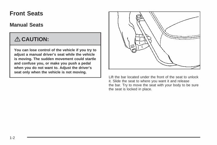
Manual Seats
{CAUTION:
You can lose control of the vehicle if you try toadjust a manual driver’s seat while the vehicleis moving. The sudden movement could startleand confuse you, or make you push a pedalwhen you do not want to. Adjust the driver’sseat only when the vehicle is not moving.
Lift the bar located under the front of the seat to unlockit. Slide the seat to where you want it and releasethe bar. Try to move the seat with your body to be surethe seat is locked in place.
1-2

Seat Height Adjuster
If your vehicle has this feature, the driver’s seat heightadjuster is located on the outboard side of the seat.
To raise the seat, move the lever upward repeatedlyuntil the seat is at the desired height. To lower the seat,move the lever downward repeatedly until the seat isat the desired height.
Power Seat
If the vehicle has a power seat, the control used tooperate it is located on the outboard side of the driver’sseat. To adjust the seat, do any of the following:• Move the seat forward or rearward by sliding the
control forward or rearward.• Raise or lower the front part of the seat cushion by
holding the front of the control up or down.• Raise or lower the entire seat by holding the rear of
the control up or down.
Driver’s Seat with Power Seat Control and PowerLumbar shown
1-3

Power Lumbar
If your vehicle has this feature, the control is located onthe outboard side of the driver’s seat cushion.
To increase support, press and hold the front of thecontrol. To decrease support, press and hold the rear ofthe control. Keep in mind that as your seating positionchanges, as it may during long trips, so should theposition of your lumbar support. Adjust the seatas needed.
Heated Seats
If your vehicle has thisfeature, the driver’s andpassenger’s heatedseat buttons are locatedon the climate controlpanel below the fan switch.
Press the button once to turn the heated seat to thehigh setting. Both lights below the heated seat symbolwill come on. Press the button a second time andthe heated seat will go to the low setting. The bottomlight will come on to indicate that the setting is onlow. Press the button a third time to turn the heatedseat off.
The heated seat feature will need to be turned on eachtime the ignition is turned off and back on again.
Driver’s side buttonshown, Passenger’sside button similar
1-4

Reclining Seatbacks
{CAUTION:
You can lose control of the vehicle if you try toadjust a manual driver’s seat while the vehicleis moving. The sudden movement could startleand confuse you, or make you push a pedalwhen you do not want to. Adjust the driver’sseat only when the vehicle is not moving.
{CAUTION:
If the seatback is not locked, it could moveforward in a sudden stop or crash. That couldcause injury to the person sitting there. Alwayspush and pull on the seatback to be sure it islocked.
The seats have reclining seatbacks. The lever used tooperate them is located on the outboard side of theseats. Lift the lever to release the seatback. Move theseatback to where you want it and release the leverto lock the seatback in place. Press rearward onthe seatback to be sure it is locked into place.
Passenger’s Side Reclining Lever shown, Driver’sSide similar
1-5
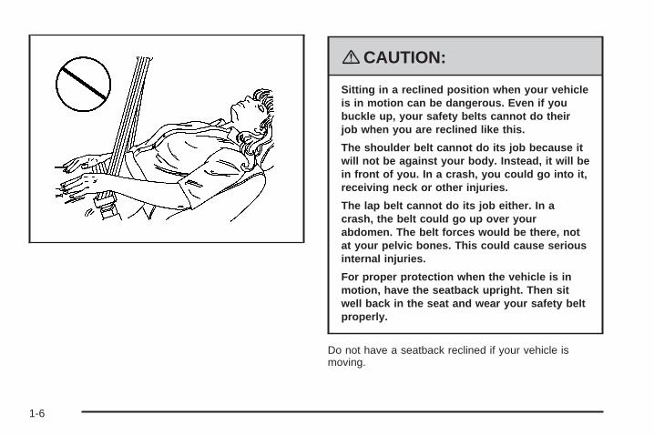
{CAUTION:
Sitting in a reclined position when your vehicleis in motion can be dangerous. Even if youbuckle up, your safety belts cannot do theirjob when you are reclined like this.
The shoulder belt cannot do its job because itwill not be against your body. Instead, it will bein front of you. In a crash, you could go into it,receiving neck or other injuries.
The lap belt cannot do its job either. In acrash, the belt could go up over yourabdomen. The belt forces would be there, notat your pelvic bones. This could cause seriousinternal injuries.
For proper protection when the vehicle is inmotion, have the seatback upright. Then sitwell back in the seat and wear your safety beltproperly.
Do not have a seatback reclined if your vehicle ismoving.
1-6

Head Restraints
Adjust the head restraint so that the top of the restraintis at the same height as the occupant’s head. Thisposition reduces the chance of a neck injury in a crash.
Pull the head restraint upto raise it. To lower thehead restraint, pressthe button, located on thetop of the seatback,and push the restraintdown. Only the front headrestraints are adjustable.
Both the front and rear head restraints can be removed.Press the button, located on the top of the seatback,and pull the restraint out from the seatback. Donot remove the head restraint if someone will be sittingin that seat while the vehicle is moving.
1-7
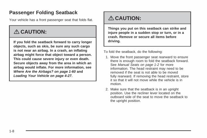
Passenger Folding SeatbackYour vehicle has a front passenger seat that folds flat.
{CAUTION:
If you fold the seatback forward to carry longerobjects, such as skis, be sure any such cargois not near an airbag. In a crash, an inflatingairbag might force that object toward a person.This could cause severe injury or even death.Secure objects away from the area in which anairbag would inflate. For more information, seeWhere Are the Airbags? on page 1-60 andLoading Your Vehicle on page 4-27.
{CAUTION:
Things you put on this seatback can strike andinjure people in a sudden stop or turn, or in acrash. Remove or secure all items beforedriving.
To fold the seatback, do the following:
1. Move the front passenger seat rearward to ensurethere is enough room to fold the seatback forward.See Manual Seats on page 1-2 for moreinformation. The head restraint may need to beremoved if the seat is not able to be movedfully rearward. If removing the head restraint, storeit so that it will not move while the vehicle is inmotion.
2. Make sure that the seatback is in an uprightposition. Use the recliner lever located on theoutboard side of the seat to move the seatback tothe upright position.
1-8

3. To fold the seat flat, pull up on either lever locatedtoward the rear of the seatback. Fold the seatforward until the seatback disengages.
4. Continue to fold the seat forward until it locks in thefolded position. Pull up on the seatback to be sureit is locked.
To raise the seatback to an upright position:
1. Pull up on either lever.
2. Push the seatback up until it is in a locked position.
{CAUTION:
If the seatback is not locked, it could moveforward in a sudden stop or crash. That couldcause injury to the person sitting there. Alwayspush and pull on the seatback to be sure it islocked.
3. Push and pull on the seatback to make sure it islocked.
1-9

Rear Seats
Split Folding Rear SeatThe seatbacks can be folded flat.
To lower the rear seatback(s):
1. Move the front seat forward and/or put the frontseatback in an upright position so it does notinterfere with folding the rear seatback forward.
2. Open the rear door while the vehicle is parked.
3. The rear head restraint may need to be removed ifit interferes with the front seat when the front seatis moved back in place. If removed, store thehead restraint where it cannot move while thevehicle is in motion.
Notice: Folding a rear seat with the safety beltsstill fastened may cause damage to the seat or thesafety belts. Always unbuckle the safety beltsand return them to their normal stowed positionbefore folding a rear seat.
4. Move the safety belt out of the way before loweringthe seatback. Do not let the safety belt get caughtbetween the seatback and seat cushion as theseatback is folded.
1-10

5. Pull up on the knoblocated on the top ofthe seatback onthe outboard side torelease the seatback.
To raise the rear seatback(s):
{CAUTION:
A safety belt that is improperly routed, notproperly attached, or twisted will not providethe protection needed in a crash. The personwearing the belt could be seriously injured.After raising the rear seatback, always checkto be sure that the safety belts are properlyrouted and attached, and are not twisted.
1. Lift the seatback up and push rearward until youhear a click. Keep the safety belt clear of the seatand not twisted.The release knob on the top of the seatback has ared ring. If the seatback is not fully latched thisring will be visible. Push on the seatback until thering is not visible.
1-11

{CAUTION:
If the seatback is not locked, it could moveforward in a sudden stop or crash. That couldcause injury to the person sitting there. Alwayspull forward on the top of the seatback at thearea of the latch to be sure it is locked.
2. Push and pull on the seatback to make sure it islocked in place.
Safety Belts
Safety Belts: They Are for EveryoneThis part of the manual tells you how to use safetybelts properly. It also tells you some things you shouldnot do with safety belts.
{CAUTION:
Do not let anyone ride where he or she cannotwear a safety belt properly. If you are in acrash and you are not wearing a safety belt,your injuries can be much worse. You can hitthings inside the vehicle harder or be ejectedfrom it and be seriously injured or killed. In thesame crash, you might not be, if you arebuckled up. Always fasten your safety belt,and check that your passenger(s) arerestrained properly too.
1-12

{CAUTION:
It is extremely dangerous to ride in a cargoarea, inside or outside of a vehicle. In acollision, people riding in these areas are morelikely to be seriously injured or killed. Do notallow people to ride in any area of your vehiclethat is not equipped with seats and safetybelts. Be sure everyone in your vehicle is in aseat and using a safety belt properly.
Your vehicle has indicators as a reminder to buckle yoursafety belts. See Safety Belt Reminders on page 3-30.
In most states and in all Canadian provinces, the lawrequires wearing safety belts. Here is why:
You never know if you will be in a crash. If you do havea crash, you do not know if it will be a serious one.
A few crashes are mild, and some crashes can be soserious that even buckled up, a person would notsurvive. But most crashes are in between. In many ofthem, people who buckle up can survive and sometimeswalk away. Without belts they could have been badlyhurt or killed.
After more than 40 years of safety belts in vehicles, thefacts are clear. In most crashes buckling up doesmatter... a lot!
1-13

Why Safety Belts WorkWhen you ride in or on anything, you go as fast asit goes.
Take the simplest vehicle. Suppose it is just a seat onwheels.
Put someone on it.
1-14

Get it up to speed. Then stop the vehicle. The riderdoes not stop.
The person keeps going until stopped by something. Ina real vehicle, it could be the windshield...
1-15

or the instrument panel... or the safety belts!
With safety belts, you slow down as the vehicle does.You get more time to stop. You stop over more distance,and your strongest bones take the forces. That is whysafety belts make such good sense.
1-16

Questions and Answers AboutSafety Belts
Q: Will I be trapped in the vehicle after a crash if Iam wearing a safety belt?
A: You could be — whether you are wearing a safetybelt or not. But your chance of being consciousduring and after an accident, so you can unbuckleand get out, is much greater if you are belted.And you can unbuckle a safety belt, even if you areupside down.
Q: If my vehicle has airbags, why should I have towear safety belts?
A: Airbags are supplemental systems only; so theywork with safety belts — not instead of them.Whether or not an airbag is provided, all occupantsstill have to buckle up to get the most protection.That is true not only in frontal collisions, butespecially in side and other collisions.
Q: If I am a good driver, and I never drive far fromhome, why should I wear safety belts?
A: You may be an excellent driver, but if you are in acrash — even one that is not your fault — you andyour passenger(s) can be hurt. Being a gooddriver does not protect you from things beyond yourcontrol, such as bad drivers.
Most accidents occur within 25 miles (40 km) ofhome. And the greatest number of serious injuriesand deaths occur at speeds of less than 40 mph(65 km/h).
Safety belts are for everyone.
1-17

How to Wear Safety Belts ProperlyThis section is only for people of adult size.
Be aware that there are special things to know aboutsafety belts and children. And there are differentrules for smaller children and babies. If a child will beriding in your vehicle, see Older Children on page 1-33or Infants and Young Children on page 1-36. Followthose rules for everyone’s protection.
It is very important for all occupants to buckle up.Statistics show that unbelted people are hurt more oftenin crashes than those who are wearing safety belts.
Occupants who are not buckled up can be thrown out ofthe vehicle in a crash. And they can strike others inthe vehicle who are wearing safety belts.
First, before you or your passenger(s) wear a safetybelt, there is important information you should know.
Sit up straight and always keep your feet on the floor infront of you. The lap part of the belt should be worn lowand snug on the hips, just touching the thighs. In a crash,this applies force to the strong pelvic bones and youwould be less likely to slide under the lap belt. If you slidunder it, the belt would apply force on your abdomen.This could cause serious or even fatal injuries. Theshoulder belt should go over the shoulder and across thechest. These parts of the body are best able to take beltrestraining forces.The shoulder belt locks if there is a sudden stop or crash.
1-18

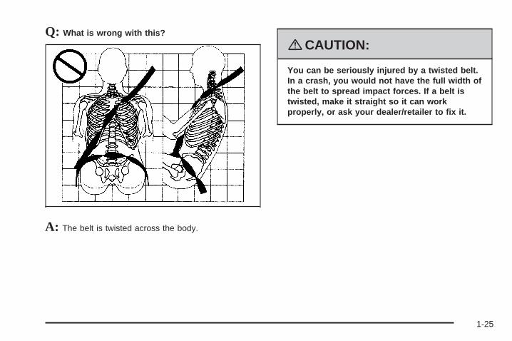
Q: What is wrong with this?
A: The shoulder belt is too loose. It will not give nearlyas much protection this way.
{CAUTION:
You can be seriously hurt if your shoulder beltis too loose. In a crash, you would moveforward too much, which could increase injury.The shoulder belt should fit snugly againstyour body.
1-19
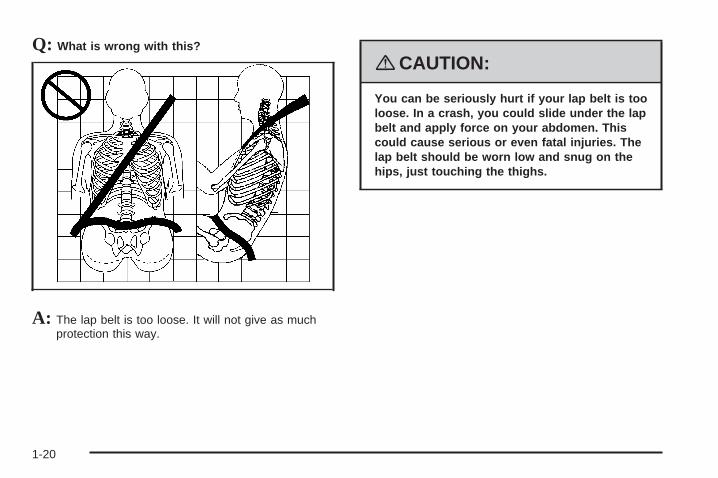
Q: What is wrong with this?
A: The lap belt is too loose. It will not give as muchprotection this way.
{CAUTION:
You can be seriously hurt if your lap belt is tooloose. In a crash, you could slide under the lapbelt and apply force on your abdomen. Thiscould cause serious or even fatal injuries. Thelap belt should be worn low and snug on thehips, just touching the thighs.
1-20

Q: What is wrong with this?
A: The belt is buckled in the wrong place.
{CAUTION:
You can be seriously injured if your belt isbuckled in the wrong place like this. In a crash,the belt would go up over your abdomen. Thebelt forces would be there, not on the pelvicbones. This could cause serious internalinjuries. Always buckle your belt into thebuckle nearest you.
1-21
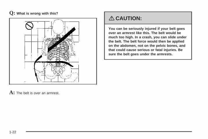
Q: What is wrong with this?
A: The belt is over an armrest.
{CAUTION:
You can be seriously injured if your belt goesover an armrest like this. The belt would bemuch too high. In a crash, you can slide underthe belt. The belt force would then be appliedon the abdomen, not on the pelvic bones, andthat could cause serious or fatal injuries. Besure the belt goes under the armrests.
1-22

Q: What is wrong with this?
A: The shoulder belt is worn under the arm. It shouldbe worn over the shoulder at all times.
{CAUTION:
You can be seriously injured if you wear theshoulder belt under your arm. In a crash, yourbody would move too far forward, which wouldincrease the chance of head and neck injury.Also, the belt would apply too much force tothe ribs, which are not as strong as shoulderbones. You could also severely injure internalorgans like your liver or spleen. The shoulderbelt should go over the shoulder and acrossthe chest.
1-23
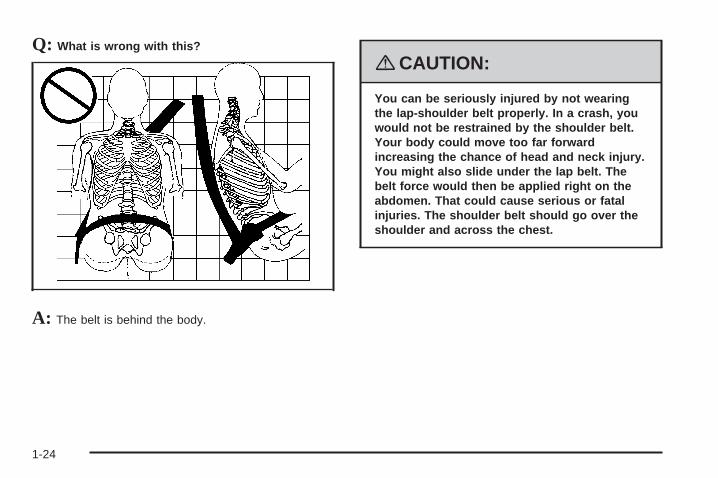
Q: What is wrong with this?
A: The belt is behind the body.
{CAUTION:
You can be seriously injured by not wearingthe lap-shoulder belt properly. In a crash, youwould not be restrained by the shoulder belt.Your body could move too far forwardincreasing the chance of head and neck injury.You might also slide under the lap belt. Thebelt force would then be applied right on theabdomen. That could cause serious or fatalinjuries. The shoulder belt should go over theshoulder and across the chest.
1-24
Q: What is wrong with this?
A: The belt is twisted across the body.
{CAUTION:
You can be seriously injured by a twisted belt.In a crash, you would not have the full width ofthe belt to spread impact forces. If a belt istwisted, make it straight so it can workproperly, or ask your dealer/retailer to fix it.
1-25

Lap-Shoulder BeltAll seating positions in your vehicle have alap-shoulder belt.
Here is how to wear a lap-shoulder belt properly.
1. Adjust the seat, if the seat is adjustable, so you cansit up straight. To see how, see “Seats” in the Index.
2. Pick up the latch plate and pull the belt across you.Do not let it get twisted.The lap-shoulder belt may lock if you pull the beltacross you very quickly. If this happens, let the beltgo back slightly to unlock it. Then pull the beltacross you more slowly.If you ever pull the shoulder portion of a passengerbelt out all the way, you may engage the childrestraint locking feature. If this happens, just let thebelt go back all the way and start again.Engaging the child restraint locking feature mayaffect the passenger sensing system. SeePassenger Sensing System on page 1-65.
3. Push the latch plate into the buckle until it clicks.Pull up on the latch plate to make sure it is secure.If the belt is not long enough, see Safety BeltExtender on page 1-32.Make sure the release button on the buckle ispositioned so you would be able to unbuckle thesafety belt quickly if necessary.
4. If equipped with a shoulder belt height adjuster,move it to the height that is right for you. Impropershoulder belt height adjustment could reducethe effectiveness of the safety belt in a crash. See“Shoulder Belt Height Adjustment” later in thissection.
1-26

5. To make the lap part tight, pull up on theshoulder belt.It may be necessary to pull stitching on the safetybelt through the latch plate to fully tighten thelap belt on smaller occupants.
To unlatch the belt, just push the button on the buckle.The belt should go back out of the way.
Before you close a door, be sure the belt is out of theway. If you slam the door on it, you can damageboth the belt and your vehicle.
1-27
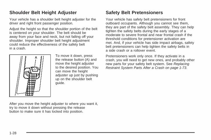
Shoulder Belt Height AdjusterYour vehicle has a shoulder belt height adjuster for thedriver and right front passenger position.
Adjust the height so that the shoulder portion of the beltis centered on your shoulder. The belt should beaway from your face and neck, but not falling off yourshoulder. Improper shoulder belt height adjustmentcould reduce the effectiveness of the safety beltin a crash.
To move it down, pressthe release button (A) andmove the height adjusterto the desired position. Youcan move the heightadjuster up just by pushingup on the shoulder beltguide.
After you move the height adjuster to where you want it,try to move it down without pressing the releasebutton to make sure it has locked into position.
Safety Belt PretensionersYour vehicle has safety belt pretensioners for frontoutboard occupants. Although you cannot see them,they are part of the safety belt assembly. They can helptighten the safety belts during the early stages of amoderate to severe frontal and near frontal crash if thethreshold conditions for pretensioner activation aremet. And, if your vehicle has side impact airbags, safetybelt pretensioners can help tighten the safety belts ina side crash or a rollover event.
Pretensioners work only once. If they activate in acrash, you will need to get new ones, and probably othernew parts for your safety belt system. See ReplacingRestraint System Parts After a Crash on page 1-73.
1-28

Rear Safety Belt Comfort GuidesRear shoulder belt comfort guides may provide addedsafety belt comfort for older children who have outgrownbooster seats and for some adults. When installed ona shoulder belt, the comfort guide positions the beltaway from the neck and head.
There is one guide for each outboard passengerposition in the rear seat. Here is how to install a comfortguide to the safety belt:
1. Pull the elastic cord out from between the edge ofthe seatback and the interior body to remove theguide from its storage clip.
1-29
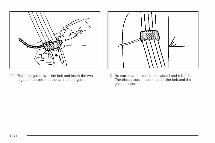
2. Place the guide over the belt and insert the twoedges of the belt into the slots of the guide.
3. Be sure that the belt is not twisted and it lies flat.The elastic cord must be under the belt and theguide on top.
1-30

{CAUTION:
A safety belt that is not properly worn may notprovide the protection needed in a crash. Theperson wearing the belt could be seriouslyinjured. The shoulder belt should go over theshoulder and across the chest. These parts ofthe body are best able to take belt restrainingforces.
4. Buckle, position, and release the safety belt asdescribed previously in this section. Make surethat the shoulder belt crosses the shoulder.
To remove and store the comfort guide, squeeze thebelt edges together so that you can take them out of theguide. Pull the guide upward to expose its storageclip, and then slide the guide onto the clip. Turnthe guide and clip inward and slide them in between theseatback and the interior body, leaving only the loopof the elastic cord exposed.
1-31
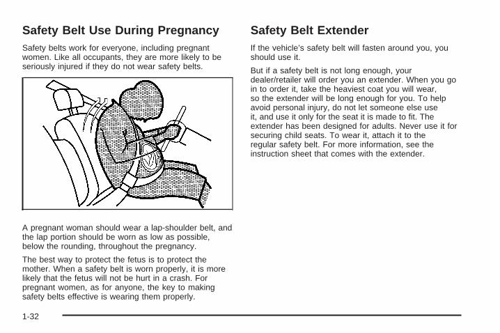
Safety Belt Use During PregnancySafety belts work for everyone, including pregnantwomen. Like all occupants, they are more likely to beseriously injured if they do not wear safety belts.
A pregnant woman should wear a lap-shoulder belt, andthe lap portion should be worn as low as possible,below the rounding, throughout the pregnancy.
The best way to protect the fetus is to protect themother. When a safety belt is worn properly, it is morelikely that the fetus will not be hurt in a crash. Forpregnant women, as for anyone, the key to makingsafety belts effective is wearing them properly.
Safety Belt ExtenderIf the vehicle’s safety belt will fasten around you, youshould use it.
But if a safety belt is not long enough, yourdealer/retailer will order you an extender. When you goin to order it, take the heaviest coat you will wear,so the extender will be long enough for you. To helpavoid personal injury, do not let someone else useit, and use it only for the seat it is made to fit. Theextender has been designed for adults. Never use it forsecuring child seats. To wear it, attach it to theregular safety belt. For more information, see theinstruction sheet that comes with the extender.
1-32

Child Restraints
Older Children
Older children who have outgrown booster seats shouldwear the vehicle’s safety belts.
The manufacturer’s instructions that come with thebooster seat, state the weight and height limitations forthat booster. Use a booster seat with a lap-shoulderbelt until the child passes the below fit test:
• Sit all the way back on the seat. Do the knees bendat the seat edge? If yes, continue. If no, return tothe booster seat.
• Buckle the lap-shoulder belt. Does the shoulder beltrest on the shoulder? If yes, continue. If no, tryusing the rear safety belt comfort guide. See “RearSafety Belt Comfort Guides” under Lap-ShoulderBelt on page 1-26 for more information. If theshoulder belt still does not rest on the shoulder,then return to the booster seat.
• Does the lap belt fit low and snug on the hips,touching the thighs? If yes, continue. If no, return tothe booster seat.
• Can proper safety belt fit be maintained for thelength of the trip? If yes, continue. If no, returnto the booster seat.
1-33
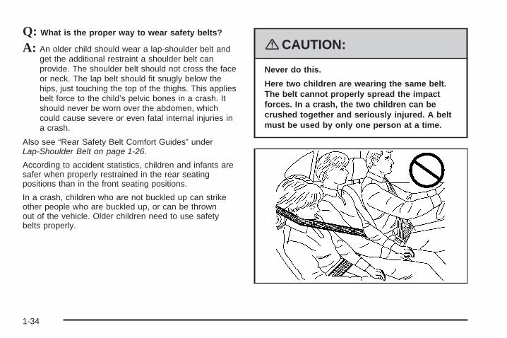
Q: What is the proper way to wear safety belts?
A: An older child should wear a lap-shoulder belt andget the additional restraint a shoulder belt canprovide. The shoulder belt should not cross the faceor neck. The lap belt should fit snugly below thehips, just touching the top of the thighs. This appliesbelt force to the child’s pelvic bones in a crash. Itshould never be worn over the abdomen, whichcould cause severe or even fatal internal injuries ina crash.
Also see “Rear Safety Belt Comfort Guides” underLap-Shoulder Belt on page 1-26.
According to accident statistics, children and infants aresafer when properly restrained in the rear seatingpositions than in the front seating positions.
In a crash, children who are not buckled up can strikeother people who are buckled up, or can be thrownout of the vehicle. Older children need to use safetybelts properly.
{CAUTION:
Never do this.
Here two children are wearing the same belt.The belt cannot properly spread the impactforces. In a crash, the two children can becrushed together and seriously injured. A beltmust be used by only one person at a time.
1-34

{CAUTION:
Never do this.
Here a child is sitting in a seat that has alap-shoulder belt, but the shoulder part isbehind the child. In a crash, the child wouldnot be restrained by the shoulder belt. Thechild might slide under the lap belt. The beltforce would then be applied right on theabdomen. That could cause serious or fatalinjuries. The child could also move too farforward increasing the chance of head andneck injury. The shoulder belt should go overthe shoulder and across the chest.
1-35

Infants and Young ChildrenEveryone in a vehicle needs protection! This includesinfants and all other children. Neither the distancetraveled nor the age and size of the traveler changesthe need, for everyone, to use safety restraints. In fact,the law in every state in the United States and inevery Canadian province says children up to some agemust be restrained while in a vehicle.
{CAUTION:
Children can be seriously injured or strangledif a shoulder belt is wrapped around their neckand the safety belt continues to tighten. Neverleave children unattended in a vehicle andnever allow children to play with the safetybelts.
Every time infants and young children ride in vehicles,they should have the protection provided by appropriaterestraints. Children who are not restrained properlycan strike other people, or can be thrown out ofthe vehicle. In addition, young children should not usethe vehicle’s adult safety belts alone; they need to use achild restraint.
1-36

{CAUTION:
People should never hold an infant in their armswhile riding in a vehicle. An infant does notweigh much — until a crash. During a crash aninfant will become so heavy it is not possible tohold it. For example, in a crash at only 25 mph(40 km/h), a 12 lb (5.5 kg) infant will suddenlybecome a 240 lb (110 kg) force on a person’sarms. An infant should be secured in anappropriate restraint.
1-37
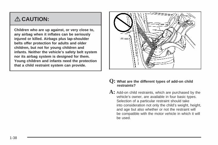
{CAUTION:
Children who are up against, or very close to,any airbag when it inflates can be seriouslyinjured or killed. Airbags plus lap-shoulderbelts offer protection for adults and olderchildren, but not for young children andinfants. Neither the vehicle’s safety belt systemnor its airbag system is designed for them.Young children and infants need the protectionthat a child restraint system can provide.
Q: What are the different types of add-on childrestraints?
A: Add-on child restraints, which are purchased by thevehicle’s owner, are available in four basic types.Selection of a particular restraint should takeinto consideration not only the child’s weight, height,and age but also whether or not the restraint willbe compatible with the motor vehicle in which it willbe used.
1-38
For most basic types of child restraints, there aremany different models available. When purchasing achild restraint, be sure it is designed to be usedin a motor vehicle. If it is, the restraint will have alabel saying that it meets federal motor vehiclesafety standards.
The restraint manufacturer’s instructions that comewith the restraint state the weight and heightlimitations for a particular child restraint. In addition,there are many kinds of restraints available forchildren with special needs.
{CAUTION:
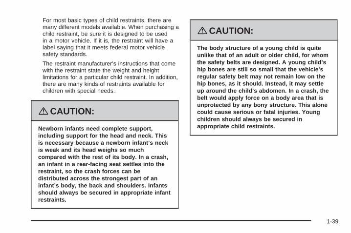
Newborn infants need complete support,including support for the head and neck. Thisis necessary because a newborn infant’s neckis weak and its head weighs so muchcompared with the rest of its body. In a crash,an infant in a rear-facing seat settles into therestraint, so the crash forces can bedistributed across the strongest part of aninfant’s body, the back and shoulders. Infantsshould always be secured in appropriate infantrestraints.
{CAUTION:
The body structure of a young child is quiteunlike that of an adult or older child, for whomthe safety belts are designed. A young child’ship bones are still so small that the vehicle’sregular safety belt may not remain low on thehip bones, as it should. Instead, it may settleup around the child’s abdomen. In a crash, thebelt would apply force on a body area that isunprotected by any bony structure. This alonecould cause serious or fatal injuries. Youngchildren should always be secured inappropriate child restraints.
1-39

Child Restraint Systems
A rear-facing infant seat (A)provides restraint with theseating surface against theback of the infant.
The harness system holds the infant in place and, in acrash, acts to keep the infant positioned in therestraint.
A forward-facing childseat (B) provides restraintfor the child’s body with theharness.
A booster seat (C-D) is a child restraint designed toimprove the fit of the vehicle’s safety belt system.A booster seat can also help a child to see out thewindow.
1-40

Securing an Add-On Child Restraint inthe Vehicle
{CAUTION:
A child can be seriously injured or killed in acrash if the child restraint is not properlysecured in the vehicle. Make sure the childrestraint is properly installed in the vehicleusing the vehicle’s safety belt or LATCHsystem, following the instructions that camewith that restraint, and also the instructions inthis manual.
To help reduce the chance of injury, the child restraintmust be secured in the vehicle. Child restraint systemsmust be secured in vehicle seats by lap belts or thelap belt portion of a lap-shoulder belt, or by the LATCHsystem. See Lower Anchors and Tethers for Children(LATCH) on page 1-43 for more information. A child canbe endangered in a crash if the child restraint is notproperly secured in the vehicle.
When securing an add-on child restraint, refer to theinstructions that come with the restraint which may be onthe restraint itself or in a booklet, or both, and to thismanual. The child restraint instructions are important, soif they are not available, obtain a replacement copyfrom the manufacturer.
Keep in mind that an unsecured child restraint canmove around in a collision or sudden stop and injurepeople in the vehicle. Be sure to properly secureany child restraint in your vehicle — even when no childis in it.
Securing the Child Within the ChildRestraint
{CAUTION:
A child can be seriously injured or killed in acrash if the child is not properly secured in thechild restraint. Because there are differentsystems, it is important to refer to theinstructions that come with the restraint. Makesure the child is properly secured, followingthe instructions that came with that restraint.
1-41

Where to Put the RestraintAccident statistics show that children are safer if theyare restrained in the rear rather than the front seat.
We recommend that children and child restraintsbe secured in a rear seat, including: an infant or a childriding in a rear-facing child restraint; a child riding ina forward-facing child seat; an older child riding ina booster seat; and children, who are large enough,using safety belts.
A label on your sun visor says, “Never put a rear-facingchild seat in the front.” This is because the risk to therear-facing child is so great, if the airbag deploys.
{CAUTION:
A child in a rear-facing child restraint can beseriously injured or killed if the right frontpassenger’s airbag inflates. This is becausethe back of the rear-facing child restraintwould be very close to the inflating airbag.
Even though the passenger sensing system isdesigned to turn off the right front passenger’sfrontal airbag if the system detects arear-facing child restraint, no system isfail-safe, and no one can guarantee that anairbag will not deploy under some unusualcircumstance, even though it is turned off. Werecommend that rear-facing child restraints besecured in a rear seat, even if the airbag is off.
If you secure a forward-facing child restraint inthe right front seat, always move the frontpassenger seat as far back as it will go. It isbetter to secure the child restraint in a rear seat.
See Passenger Sensing System on page 1-65for additional information.
1-42

If your vehicle does not have a rear seat that willaccommodate a rear-facing child restraint, werecommend that rear-facing child restraints not betransported in your vehicle, even if the airbag is off.
When securing a child restraint in a rear seatingposition, study the instructions that came with your childrestraint to make sure it is compatible with this vehicle.
Wherever you install a child restraint, be sure tosecure the child restraint properly.
Keep in mind that an unsecured child restraint can movearound in a collision or sudden stop and injure people inthe vehicle. Be sure to properly secure any child restraintin your vehicle — even when no child is in it.
Lower Anchors and Tethers forChildren (LATCH)The LATCH system holds a child restraint during drivingor in a crash. This system is designed to makeinstallation of a child restraint easier. The LATCHsystem uses anchors in the vehicle and attachments onthe child restraint that are made for use with theLATCH system.
Make sure that a LATCH-compatible child restraint isproperly installed using the anchors, or use the vehicle’ssafety belts to secure the restraint, following theinstructions that came with that restraint, and also theinstructions in this manual. When installing a childrestraint with a top tether, you must also use either thelower anchors or the safety belts to properly securethe child restraint. A child restraint must never beattached using only the top tether and anchor.
In order to use the LATCH system in your vehicle, youneed a child restraint that has LATCH attachments.The child restraint manufacturer will provide youwith instructions on how to use the child restraint and itsattachments. The following explains how to attach achild restraint with these attachments in your vehicle.
Not all vehicle seating positions or child restraints havelower anchors and attachments or top tether anchorsand attachments.
1-43
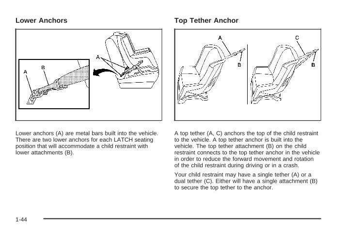
Lower Anchors
Lower anchors (A) are metal bars built into the vehicle.There are two lower anchors for each LATCH seatingposition that will accommodate a child restraint withlower attachments (B).
Top Tether Anchor
A top tether (A, C) anchors the top of the child restraintto the vehicle. A top tether anchor is built into thevehicle. The top tether attachment (B) on the childrestraint connects to the top tether anchor in the vehiclein order to reduce the forward movement and rotationof the child restraint during driving or in a crash.
Your child restraint may have a single tether (A) or adual tether (C). Either will have a single attachment (B)to secure the top tether to the anchor.
1-44
Some child restraints that have a top tether are designedfor use with or without the top tether being attached.Others require the top tether always to be attached. InCanada, the law requires that forward-facing childrestraints have a top tether, and that the tether beattached. Be sure to read and follow the instructions foryour child restraint.
If the child restraint does not have a top tether, one canbe obtained, in kit form, for many child restraints. Askthe child restraint manufacturer whether or not a kitis available.
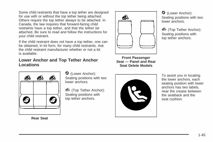
Lower Anchor and Top Tether AnchorLocations
j (Lower Anchor):Seating positions with twolower anchors.
i (Top Tether Anchor):Seating positions withtop tether anchors.
j (Lower Anchor):Seating positions with twolower anchors.
i (Top Tether Anchor):Seating positions withtop tether anchors.
To assist you in locatingthe lower anchors, eachseating position with loweranchors has two labels,near the crease betweenthe seatback and theseat cushion.
Rear Seat
Front PassengerSeat — Panel and Rear
Seat Delete Models
1-45

To assist you in locatingthe top tether anchors, thissymbol will be located onthe storage compartmentfor the rear center position,on the lower side quarterpanels for the rear outboardpositions and on the cargomat behind the rear seats.
The rear outboard top tether anchors are located onthe cargo floor behind the rear seats. The rear centertop tether anchor is located in a storage compartmentbehind the rear seats. Lift the lid of the storagecompartment to access the anchor. You may haveto fold back the cargo mat to access the storagecompartment and the top tether anchor for the rearcenter seating position. Be sure to use an anchorlocated on the same side of the vehicle as the seatingposition where the child restraint will be placed.
Vehicles with Rear Seats
1-46

If your vehicle does not have a rear seat, there will bean exposed top tether anchor for the front passengerposition located on the rear passenger side pillar behindthe front passenger seat.
Do not secure a child restraint in a position without atop tether anchor if a national or local law requires thatthe top tether be attached, or if the instructions thatcome with the child restraint say that the top tether mustbe attached.
Accident statistics show that children are safer if theyare restrained in the rear rather than the front seat. SeeWhere to Put the Restraint on page 1-42 for additionalinformation.
Vehicles without Rear Seats — Panel and Rear SeatDelete Models
1-47

Securing a Child Restraint Designed forthe LATCH System
{CAUTION:
If a LATCH-type child restraint is not attachedto anchors, the restraint will not be able toprotect the child correctly. In a crash, the childcould be seriously injured or killed. Make surethat a LATCH-type child restraint is properlyinstalled using the anchors, or use thevehicle’s safety belts to secure the restraint,following the instructions that came with thatrestraint, and also the instructions in thismanual.
{CAUTION:
Each top tether anchor and lower anchor in thevehicle is designed to hold only one childrestraint. Attaching more than one childrestraint to a single anchor could cause theanchor or attachment to come loose or evenbreak during a crash. A child or others couldbe injured if this happens. To help preventinjury to people and damage to your vehicle,attach only one child restraint per anchor.
1-48

{CAUTION:
Children can be seriously injured or strangledif a shoulder belt is wrapped around their neckand the safety belt continues to tighten.Secure any unused safety belts behind thechild restraint so children cannot reach them.Pull the shoulder belt all the way out of theretractor to set the lock, if your vehicle hasone, after the child restraint has been installed.Be sure to follow the instructions of the childrestraint manufacturer.
Notice: Contact between the child restraint LATCHattachment parts and the vehicle’s safety beltassembly may cause damage to these parts. Makesure when securing unused safety belts behindthe child restraint that there is no contact betweenthe child restraint LATCH attachment parts andthe vehicle’s safety belt assembly.
Folding an empty rear seat with the safety beltssecured may cause damage to the safety belt or theseat. When removing the child restraint, alwaysremember to return the safety belts to their normal,stowed position before folding the rear seat.
1. Attach and tighten the lower attachments to thelower anchors. If the child restraint does not havelower attachments or the desired seating positiondoes not have lower anchors, secure the childrestraint with the top tether and the safety belts.Refer to your child restraint manufacturerinstructions and the instructions in this manual.
1.1. Find the lower anchors for the desiredseating position.
1.2. Put the child restraint on the seat.1.3. Attach and tighten the lower attachments on
the child restraint to the lower anchors.
2. If the child restraint manufacturer recommends thatthe top tether be attached, attach and tighten thetop tether to the top tether anchor, if equipped.Refer to the child restraint instructions andthe following steps:
2.1. To secure a child restraint in the rear centerseating position, find the storagecompartment behind the rear seats. You mayhave to fold back the cargo mat to accessthe storage compartment and the toptether anchor.
2.2. Lift the lid of the storage compartment toaccess the top tether anchor for the rearcenter seating position.
1-49
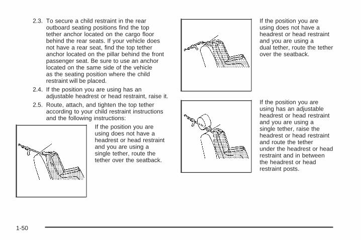
2.3. To secure a child restraint in the rearoutboard seating positions find the toptether anchor located on the cargo floorbehind the rear seats. If your vehicle doesnot have a rear seat, find the top tetheranchor located on the pillar behind the frontpassenger seat. Be sure to use an anchorlocated on the same side of the vehicleas the seating position where the childrestraint will be placed.
2.4. If the position you are using has anadjustable headrest or head restraint, raise it.
2.5. Route, attach, and tighten the top tetheraccording to your child restraint instructionsand the following instructions:
If the position you areusing does not have aheadrest or head restraintand you are using asingle tether, route thetether over the seatback.
If the position you areusing does not have aheadrest or head restraintand you are using adual tether, route the tetherover the seatback.
If the position you areusing has an adjustableheadrest or head restraintand you are using asingle tether, raise theheadrest or head restraintand route the tetherunder the headrest or headrestraint and in betweenthe headrest or headrestraint posts.
1-50

If the position you areusing has an adjustableheadrest or head restraintand you are using adual tether, route the tetheraround the headrest orhead restraint.
3. Push and pull the child restraint in differentdirections to be sure it is secure.
Securing a Child Restraint in a RearSeat PositionWhen securing a child restraint in a rear seatingposition, study the instructions that came with your childrestraint to make sure it is compatible with this vehicle.
If your child restraint has the LATCH system, see LowerAnchors and Tethers for Children (LATCH) onpage 1-43 for how to install your child restraint usingLATCH. If you secure a child restraint using a safety beltand it uses a top tether, see Lower Anchors andTethers for Children (LATCH) on page 1-43 for toptether anchor locations.
Do not secure a child seat in a position without a toptether anchor if a national or local law requires that thetop tether be anchored, or if the instructions thatcome with the child restraint say that the top strap mustbe anchored.
In Canada, the law requires that forward-facing childrestraints have a top tether, and that the tether beattached.
If your child restraint does not have the LATCH system,you will be using the safety belt to secure the childrestraint in this position. Be sure to follow theinstructions that came with the child restraint. Securethe child in the child restraint when and as theinstructions say.
1-51
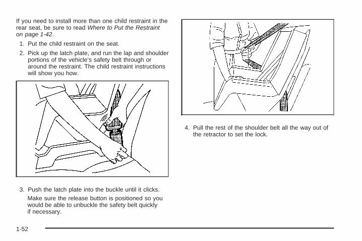
If you need to install more than one child restraint in therear seat, be sure to read Where to Put the Restrainton page 1-42.
1. Put the child restraint on the seat.
2. Pick up the latch plate, and run the lap and shoulderportions of the vehicle’s safety belt through oraround the restraint. The child restraint instructionswill show you how.
3. Push the latch plate into the buckle until it clicks.Make sure the release button is positioned so youwould be able to unbuckle the safety belt quicklyif necessary.
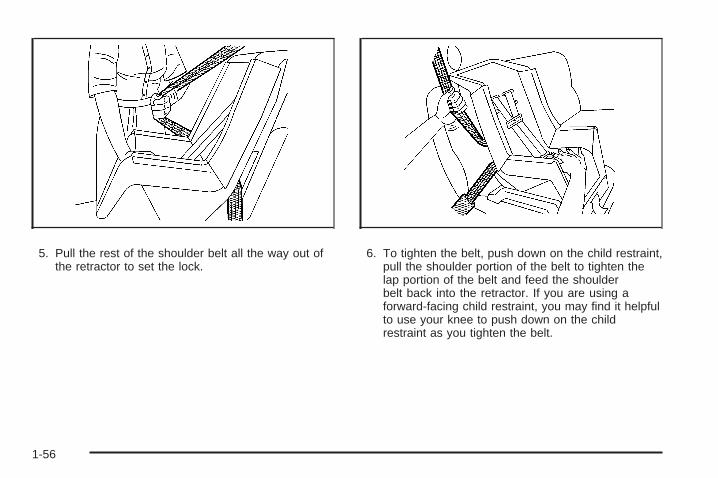
4. Pull the rest of the shoulder belt all the way out ofthe retractor to set the lock.
1-52

5. To tighten the belt, push down on the child restraint,pull the shoulder portion of the belt to tighten thelap portion of the belt, and feed the shoulderbelt back into the retractor. If you are using aforward-facing child restraint, you may find it helpfulto use your knee to push down on the childrestraint as you tighten the belt.
6. If your child restraint has a top tether, follow thechild restraint manufacturer’s instructions regardingthe use of the top tether. See Lower Anchorsand Tethers for Children (LATCH) on page 1-43 formore information.
7. Push and pull the child restraint in differentdirections to be sure it is secure.
To remove the child restraint, unbuckle the vehicle’ssafety belt and let it go back all the way. If the top tetheris attached to a top tether anchor, disconnect it.
Securing a Child Restraint in theRight Front Seat PositionYour vehicle has airbags. A rear seat is a safer place tosecure a forward-facing child restraint. See Where toPut the Restraint on page 1-42.
In addition, your vehicle has a passenger sensingsystem which is designed to turn off the right frontpassenger’s frontal airbag under certain conditions. SeePassenger Sensing System on page 1-65 andPassenger Airbag Status Indicator on page 3-32 formore information on this, including important safetyinformation.
1-53

A label on your sun visor says, “Never put a rear-facingchild seat in the front.” This is because the risk to therear-facing child is so great, if the airbag deploys.
{CAUTION:
A child in a rear-facing child restraint can beseriously injured or killed if the right frontpassenger’s airbag inflates. This is becausethe back of the rear-facing child restraintwould be very close to the inflating airbag.
Even though the passenger sensing system isdesigned to turn off the right front passenger’sfrontal airbag if the system detects arear-facing child restraint, no system isfail-safe, and no one can guarantee that anairbag will not deploy under some unusualcircumstance, even though it is turned off. Werecommend that rear-facing child restraints besecured in a rear seat, even if the airbag is off.
CAUTION: (Continued)
CAUTION: (Continued)
If you secure a forward-facing childrestraint in the right front seat, alwaysmove the front passenger seat as far backas it will go. It is better to secure the childrestraint in a rear seat.
See Passenger Sensing System onpage 1-65 for additional information.
If your vehicle does not have a rear seat that willaccommodate a rear-facing child restraint, werecommend that rear-facing child restraints not betransported in your vehicle, even if the airbag is off.
If your child restraint has the LATCH system, see LowerAnchors and Tethers for Children (LATCH) onpage 1-43 for how to install your child restraint usingLATCH. If you secure a child restraint using a safety beltand it uses a top tether, see Lower Anchors andTethers for Children (LATCH) on page 1-43 for toptether anchor locations.
1-54

Do not secure a child seat in a position without a toptether anchor if a national or local law requires that thetop tether be anchored, or if the instructions thatcome with the child restraint say that the top strap mustbe anchored.
In Canada, the law requires that forward-facing childrestraints have a top tether, and that the tether beattached.
You will be using the lap-shoulder belt to secure thechild restraint in this position. Follow the instructions thatcame with the child restraint.
1. Move the seat as far back as it will go beforesecuring the forward-facing child restraint.When the passenger sensing system has turned offthe right front passenger’s frontal airbag, the offindicator on the passenger airbag status indicatorshould light and stay lit when you start thevehicle. See Passenger Airbag Status Indicator onpage 3-32.
2. Put the child restraint on the seat.
3. Pick up the latch plate, and run the lap and shoulderportions of the vehicle’s safety belt through oraround the restraint. The child restraint instructionswill show you how.
4. Push the latch plate into the buckle until it clicks.Make sure the release button is positioned so youwould be able to unbuckle the safety belt quicklyif necessary.
1-55
5. Pull the rest of the shoulder belt all the way out ofthe retractor to set the lock.
6. To tighten the belt, push down on the child restraint,pull the shoulder portion of the belt to tighten thelap portion of the belt and feed the shoulderbelt back into the retractor. If you are using aforward-facing child restraint, you may find it helpfulto use your knee to push down on the childrestraint as you tighten the belt.
1-56

7. If your vehicle does not have a rear seat and yourchild restraint has a top tether, follow the childrestraint manufacturer’s instructions regarding theuse of the top tether. See Lower Anchors andTethers for Children (LATCH) on page 1-43 for moreinformation.
8. Push and pull the child restraint in differentdirections to be sure it is secure.
If the airbag is off, the off indicator in the passengerairbag status indicator will come on and stay on whenthe vehicle is started.
If a child restraint has been installed and the onindicator is lit, turn the vehicle off. Remove the childrestraint from the vehicle and reinstall the child restraint.
If, after reinstalling the child restraint and restartingthe vehicle, the on indicator is still lit, check to makesure that the vehicle’s seatback is not pressing the childrestraint into the seat cushion. If this happens, slightlyrecline the vehicle’s seatback and adjust the seatcushion if possible. Also make sure the child restraint isnot trapped under the vehicle head restraint. If thishappens, adjust the head restraint.
Remove any additional material from the seat such asblankets, cushions, seat covers, seat heaters orseat massagers before reinstalling or securing the childrestraint.
If the on indicator is still lit, secure the child in the childrestraint in a rear seat position in the vehicle andcheck with your dealer/retailer. If no rear seat isavailable, do not install a child restraint in this vehicleand check with your dealer/retailer.
To remove the child restraint, unbuckle the vehicle’ssafety belt and let it go back all the way. If the top tetheris attached to a top tether anchor, disconnect it.
Airbag SystemYour vehicle has the following airbags:
• A frontal airbag for the driver.
• A frontal airbag for the right front passenger
Your vehicle may also have the following airbags:
• A roof-rail airbag for the driver and the passengerseated directly behind the driver.
• A roof-rail airbag for the right front passenger andthe passenger seated directly behind the rightfront passenger.
All of the airbags in your vehicle will have the wordAIRBAG embossed in the trim or on an attached labelnear the deployment opening.
1-57

For frontal airbags, the word AIRBAG will appear on themiddle part of the steering wheel for the driver andon the instrument panel for the right front passenger.
With roof-rail airbags, the word AIRBAG will appearalong the headliner or trim.
Airbags are designed to supplement the protectionprovided by safety belts. Even though today’s airbagsare also designed to help reduce the risk of injuryfrom the force of an inflating bag, all airbags must inflatevery quickly to do their job.
Here are the most important things to know about theairbag system:
{CAUTION:
You can be severely injured or killed in a crashif you are not wearing your safety belt — evenif you have airbags. Wearing your safety beltduring a crash helps reduce your chance ofhitting things inside the vehicle or beingejected from it. Airbags are “supplementalrestraints” to the safety belts. All airbags aredesigned to work with safety belts, but do notreplace them.
{CAUTION:
Frontal airbags are designed to deploy inmoderate to severe frontal and near frontalcrashes. They are not designed to inflate inrollover, rear crashes, or in many side crashes.
If your vehicle has rollover capable roof-railairbags, they are designed to inflate inmoderate to severe crashes where somethinghits the side of your vehicle and in the event ofa vehicle rollover. They are not designed toinflate in frontal or in rear crashes.
Everyone in your vehicle should wear a safetybelt properly — whether or not there is anairbag for that person.
1-58
{CAUTION:
Airbags inflate with great force, faster than theblink of an eye. Anyone who is up against, orvery close to, any airbag when it inflates canbe seriously injured or killed. Do not situnnecessarily close to the airbag, as youwould be if you were sitting on the edge ofyour seat or leaning forward. Safety belts helpkeep you in position before and during acrash. Always wear your safety belt, even withairbags. The driver should sit as far back aspossible while still maintaining control of thevehicle.
Occupants should not lean on or sleep againstthe door or side windows in seating positionswith roof-rail airbags.
{CAUTION:
Airbags plus lap-shoulder belts offer the bestprotection for adults, but not for youngchildren and infants. Neither the vehicle’ssafety belt system nor its airbag system isdesigned for them. Young children and infantsneed the protection that a child restraintsystem can provide. Always secure childrenproperly in your vehicle. To read how, seeOlder Children on page 1-33 or Infants andYoung Children on page 1-36.
There is an airbagreadiness light on theinstrument panel cluster,which shows the airbagsymbol.
The system checks the airbag electrical system formalfunctions. The light tells you if there is an electricalproblem. See Airbag Readiness Light on page 3-31for more information.
1-59

Where Are the Airbags?
The driver’s frontal airbag is in the middle of thesteering wheel.
The right front passenger’s airbag is in the instrumentpanel on the passenger’s side.
1-60

If your vehicle has roof-rail airbags for the driver, rightfront passenger, and second row outboard passengers,they are in the ceiling above the side windows.
{CAUTION:
If something is between an occupant and anairbag, the airbag might not inflate properly orit might force the object into that personcausing severe injury or even death. The pathof an inflating airbag must be kept clear. Donot put anything between an occupant and anairbag, and do not attach or put anything onthe steering wheel hub or on or near any otherairbag covering.
If your vehicle has roof-rail airbags, neversecure anything to the roof of your vehicle byrouting the rope or tie down through any dooror window opening. If you do, the path of aninflating roof-rail airbag will be blocked.
Driver Side shown, Passenger Side similar
1-61

When Should an Airbag Inflate?Frontal airbags are designed to inflate in moderate tosevere frontal or near-frontal crashes to help reduce thepotential for severe injuries mainly to the driver’s orright front passenger’s head and chest. However, theyare only designed to inflate if the impact exceeds apredetermined deployment threshold. Deploymentthresholds are used to predict how severe a crash islikely to be in time for the airbags to inflate andhelp restrain the occupants.
Whether your frontal airbags will or should deploy is notbased on how fast your vehicle is traveling. It dependslargely on what you hit, the direction of the impact,and how quickly your vehicle slows down.
Frontal airbags may inflate at different crash speeds.For example:
• If the vehicle hits a stationary object, the airbagscould inflate at a different crash speed than if thevehicle hits a moving object.
• If the vehicle hits an object that deforms, theairbags could inflate at a different crash speed thanif the vehicle hits an object does not deform.
• If the vehicle hits a narrow object (like a pole), theairbags could inflate at a different crash speedthan if the vehicle hits a wide object (like a wall).
• If the vehicle goes into an object at an angle, theairbags could inflate at a different crash speedthan if the vehicle goes straight into the object.
Thresholds can also vary with specific vehicle design.
Frontal airbags are not intended to inflate during vehiclerollovers, rear impacts, or in many side impacts.
In addition, your vehicle has dual-stage frontal airbags.Dual-stage airbags adjust the restraint according tocrash severity. Your vehicle has an electronic frontalsensor, which helps the sensing system distinguishbetween a moderate frontal impact and a more severefrontal impact. For moderate frontal impacts, dual-stageairbags inflate at a level less than full deployment.For more severe frontal impacts, full deployment occurs.
Your vehicle may or may not have roof-rail airbags.See Airbag System on page 1-57. Roof-rail airbags areintended to inflate in moderate to severe side crashes.In addition, these roof-rail airbags are intended to inflateduring a rollover. Roof-rail airbags will inflate if thecrash severity is above the system’s designed thresholdlevel. The threshold level can vary with specificvehicle design.
Roof-rail airbags are not intended to inflate in frontalimpacts, near-frontal impacts, or rear impacts. A roof-railairbag is intended to deploy on the side of the vehiclethat is struck or if the sensing system predicts thatthe vehicle is about to roll over.
1-62
In any particular crash, no one can say whether anairbag should have inflated simply because of thedamage to a vehicle or because of what the repair costswere. For frontal airbags, inflation is determined bywhat the vehicle hits, the angle of the impact, and howquickly the vehicle slows down. For roof-rail airbags,deployment is determined by the location and severity ofthe side impact. In a rollover event, roof-rail airbagdeployment is determined by the direction of the roll.
What Makes an Airbag Inflate?In a deployment event, the sensing system sends anelectrical signal triggering a release of gas fromthe inflator. Gas from the inflator fills the airbag causingthe bag to break out of the cover and deploy. Theinflator, the airbag, and related hardware are all part ofthe airbag module.
Frontal airbag modules are located inside the steeringwheel and instrument panel. For vehicles withroof-rail airbags, there are airbag modules in the ceilingof the vehicle, near the side windows that haveoccupant seating positions.
How Does an Airbag Restrain?In moderate to severe frontal or near frontal collisions,even belted occupants can contact the steering wheel orthe instrument panel. In moderate to severe sidecollisions, even belted occupants can contact the insideof the vehicle.
Airbags supplement the protection provided by safetybelts. Frontal airbags distribute the force of theimpact more evenly over the occupant’s upper body,stopping the occupant more gradually. Roof-rail airbagsdistribute the force of the impact more evenly overthe occupant’s upper body.
Rollover capable roof-rail airbags are designed to helpcontain the head and chest of occupants in theoutboard seating positions in the first and second rows.The rollover capable roof-rail airbags are designed tohelp reduce the risk of full or partial ejection in rolloverevents, although no system can prevent all suchejections.
But airbags would not help in many types of collisions,primarily because the occupant’s motion is nottoward those airbags. See When Should an AirbagInflate? on page 1-62 for more information.
Airbags should never be regarded as anything morethan a supplement to safety belts.
1-63

What Will You See After an AirbagInflates?After the frontal airbags inflate, they quickly deflate, soquickly that some people may not even realize anairbag inflated. Roof-rail airbags may still be at leastpartially inflated for some time after they deploy. Somecomponents of the airbag module may be hot forseveral minutes. For location of the airbag modules, seeWhat Makes an Airbag Inflate? on page 1-63.
The parts of the airbag that come into contact with youmay be warm, but not too hot to touch. There maybe some smoke and dust coming from the vents in thedeflated airbags. Airbag inflation does not preventthe driver from seeing out of the windshield or beingable to steer the vehicle, nor does it prevent people fromleaving the vehicle.
{CAUTION:
When an airbag inflates, there may be dust inthe air. This dust could cause breathingproblems for people with a history of asthmaor other breathing trouble. To avoid this,everyone in the vehicle should get out as soonas it is safe to do so. If you have breathingproblems but cannot get out of the vehicleafter an airbag inflates, then get fresh air byopening a window or a door. If you experiencebreathing problems following an airbagdeployment, you should seek medicalattention.
Your vehicle has a feature that may automaticallyunlock the doors, turn the interior lamps on, and turnthe hazard warning flashers on when the airbags inflate.You can lock the doors, turn the interior lamps off,and turn the hazard warning flashers off by using thecontrols for those features.
In many crashes severe enough to inflate the airbag,windshields are broken by vehicle deformation.Additional windshield breakage may also occur from theright front passenger airbag.
1-64

• Airbags are designed to inflate only once. After anairbag inflates, you will need some new parts forthe airbag system. If you do not get them, the airbagsystem will not be there to help protect you inanother crash. A new system will include airbagmodules and possibly other parts. The servicemanual for your vehicle covers the need to replaceother parts.
• Your vehicle has a crash sensing and diagnosticmodule which records information after a crash.See Vehicle Data Recording and Privacy onpage 7-16 and Event Data Recorders on page 7-16.
• Let only qualified technicians work on the airbagsystems. Improper service can mean that anairbag system will not work properly. See yourdealer/retailer for service.
Passenger Sensing SystemYour vehicle has a passenger sensing system for theright front passenger’s position. The passengerairbag status indicator will be visible on the instrumentpanel when you start your vehicle.
The words ON and OFF, or the symbol for on and off,will be visible during the system check. If you areusing remote start to start your vehicle from a distance,if equipped, you may not see the system check.When the system check is complete, either the wordON or the word OFF, or the symbol for on or the symbolfor off, will be visible. See Passenger Airbag StatusIndicator on page 3-32.
The passenger sensing system will turn off the rightfront passenger’s frontal airbag under certain conditions.The driver’s airbags are not part of the passengersensing system.
United States Canada
1-65

The passenger sensing system works with sensors thatare part of the right front passenger’s seat and safetybelt. The sensors are designed to detect the presence ofa properly-seated occupant and determine if the rightfront passenger’s frontal airbag should be enabled (mayinflate) or not.
Accident statistics show that children are safer if theyare restrained in the rear rather than the front seat.
We recommend that children be secured in a rear seat,including: an infant or a child riding in a rear-facingchild restraint; a child riding in a forward-facing childseat; an older child riding in a booster seat; and children,who are large enough, using safety belts.
A label on your sun visor says, “Never put a rear-facingchild seat in the front.” This is because the risk to therear-facing child is so great, if the airbag deploys.
{CAUTION:
A child in a rear-facing child restraint can beseriously injured or killed if the right frontpassenger’s airbag inflates. This is becausethe back of the rear-facing child restraintwould be very close to the inflating airbag.
Even though the passenger sensing system isdesigned to turn off the right front passenger’sfrontal airbag if the system detects arear-facing child restraint, no system isfail-safe, and no one can guarantee that anairbag will not deploy under some unusualcircumstance, even though it is turned off. Werecommend that rear-facing child restraints besecured in a rear seat, even if the airbag is off.
If you secure a forward-facing child restraint inthe right front seat, always move the frontpassenger seat as far back as it will go. It isbetter to secure the child restraint in a rear seat.
1-66

If your vehicle does not have a rear seat that willaccommodate a rear-facing child restraint, werecommend that rear-facing child restraints not betransported in your vehicle, even if the airbag is off.
The passenger sensing system is designed to turn offthe right front passenger’s frontal airbag if:
• The right front passenger seat is unoccupied.
• The system determines that an infant is present ina rear-facing infant seat.
• The system determines that a small child is presentin a child restraint.
• The system determines that a small child is presentin a booster seat.
• A right front passenger takes his/her weight off ofthe seat for a period of time.
• The right front passenger seat is occupied by asmaller person, such as a child who has outgrownchild restraints.
• Or, if there is a critical problem with the airbagsystem or the passenger sensing system.
When the passenger sensing system has turned off theright front passenger’s frontal airbag, the off indicatorwill light and stay lit to remind you that the airbag is off.See Passenger Airbag Status Indicator on page 3-32.
If a child restraint has been installed and the onindicator is lit, turn the vehicle off. Remove the childrestraint from the vehicle and reinstall the child restraintfollowing the child restraint manufacturer’s directionsand refer to Securing a Child Restraint in the Right FrontSeat Position on page 1-53.
If, after reinstalling the child restraint and restarting thevehicle, the on indicator is still lit, check to makesure that the vehicle’s seatback is not pressing the childrestraint into the seat cushion. If this happens, slightlyrecline the vehicle’s seatback and adjust the seatcushion if possible. Also make sure the child restraint isnot trapped under the vehicle head restraint. If thishappens, adjust the head restraint. See Head Restraintson page 1-7.
Remove any additional material from the seat such asblankets, cushions, seat covers, seat heaters, orseat massagers before reinstalling or securing the childrestraint.
If the on indicator is still lit, secure the child in the childrestraint in a rear seat position in the vehicle, andcheck with your dealer/retailer. If no rear seat isavailable, do not install a child restraint in this vehicle,and check with your dealer/retailer.
1-67
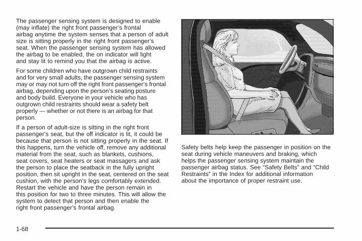
The passenger sensing system is designed to enable(may inflate) the right front passenger’s frontalairbag anytime the system senses that a person of adultsize is sitting properly in the right front passenger’sseat. When the passenger sensing system has allowedthe airbag to be enabled, the on indicator will lightand stay lit to remind you that the airbag is active.
For some children who have outgrown child restraintsand for very small adults, the passenger sensing systemmay or may not turn off the right front passenger’s frontalairbag, depending upon the person’s seating postureand body build. Everyone in your vehicle who hasoutgrown child restraints should wear a safety beltproperly — whether or not there is an airbag for thatperson.
If a person of adult-size is sitting in the right frontpassenger’s seat, but the off indicator is lit, it could bebecause that person is not sitting properly in the seat. Ifthis happens, turn the vehicle off, remove any additionalmaterial from the seat, such as blankets, cushions,seat covers, seat heaters or seat massagers and askthe person to place the seatback in the fully uprightposition, then sit upright in the seat, centered on the seatcushion, with the person’s legs comfortably extended.Restart the vehicle and have the person remain inthis position for two to three minutes. This will allow thesystem to detect that person and then enable theright front passenger’s frontal airbag.
Safety belts help keep the passenger in position on theseat during vehicle maneuvers and braking, whichhelps the passenger sensing system maintain thepassenger airbag status. See “Safety Belts” and “ChildRestraints” in the Index for additional informationabout the importance of proper restraint use.
1-68

If you ever pull the shoulder portion of the belt out allthe way, you will engage the child restraint lockingfeature. This may unintentionally cause the passengersensing system to turn the airbag(s) off for someadult size occupants. If this happens, just let the belt goback all the way and start again.
{CAUTION:
If the airbag readiness light in the instrumentpanel cluster ever comes on and stays on, itmeans that something may be wrong with theairbag system. If this ever happens, have thevehicle serviced promptly, because anadult-size person sitting in the right frontpassenger’s seat may not have the protectionof the airbag(s). See Airbag Readiness Lighton page 3-31 for more on this, includingimportant safety information.
A thick layer of additional material, such as a blanket orcushion, or aftermarket equipment such as seatcovers, seat heaters, and seat massagers can affecthow well the passenger sensing system operates.We recommend that you not use seat covers or otheraftermarket equipment other than any that GM hasapproved for your specific vehicle. See AddingEquipment to Your Airbag-Equipped Vehicle onpage 1-71 for more information about modifications thatcan affect how the system operates.
{CAUTION:
Stowing of articles under the passenger’s seator between the passenger’s seat cushion andseatback may interfere with the properoperation of the passenger sensing system.
1-69

Servicing Your Airbag-EquippedVehicleAirbags affect how your vehicle should be serviced.There are parts of the airbag system in several placesaround your vehicle. Your dealer/retailer and the servicemanual have information about servicing your vehicleand the airbag system. To purchase a service manual,see Service Publications Ordering Information onpage 7-15.
{CAUTION:
For up to 10 seconds after the ignition isturned off and the battery is disconnected, anairbag can still inflate during improper service.You can be injured if you are close to anairbag when it inflates. Avoid yellowconnectors. They are probably part of theairbag system. Be sure to follow properservice procedures, and make sure the personperforming work for you is qualified to do so.
1-70

Adding Equipment to YourAirbag-Equipped Vehicle
Q: Is there anything I might add to or changeabout the vehicle that could keep the airbagsfrom working properly?
A: Yes. If you add things that change your vehicle’sframe, bumper system, height, front end or sidesheet metal, they may keep the airbag system fromworking properly. Changing or moving any partsof the front seats, safety belts, the airbag sensingand diagnostic module, steering wheel, instrumentpanel, roof-rail airbag modules, ceiling headlineror pillar garnish trim, front sensors, side impactsensors, rollover sensor module, or airbag wiringcan affect the operation of the airbag system.
In addition, your vehicle has a passenger sensingsystem for the right front passenger’s position,which includes sensors that are part of thepassenger’s seat. The passenger sensing systemmay not operate properly if the original seat
trim is replaced with non-GM covers, upholstery ortrim, or with GM covers, upholstery or trimdesigned for a different vehicle. Any object, such asan aftermarket seat heater or a comfort enhancingpad or device, installed under or on top of theseat fabric, could also interfere with the operation ofthe passenger sensing system. This could eitherprevent proper deployment of the passengerairbag(s) or prevent the passenger sensing systemfrom properly turning off the passenger airbag(s).See Passenger Sensing System on page 1-65.
If you have any questions about this, you shouldcontact Customer Assistance before you modifyyour vehicle. The phone numbers and addresses forCustomer Assistance are in Step Two of theCustomer Satisfaction Procedure in this manual.See Customer Satisfaction Procedure on page 7-2.
If your vehicle has rollover roof-rail airbags, seeDifferent Size Tires and Wheels on page 5-71for additional important information.
1-71

Q: Because I have a disability, I have to get myvehicle modified. How can I find out whetherthis will affect my airbag system?
A: If you have questions, call Customer Assistance.The phone numbers and addresses for CustomerAssistance are in Step Two of the CustomerSatisfaction Procedure in this manual. SeeCustomer Satisfaction Procedure on page 7-2.
In addition, your dealer/retailer and the service manualhave information about the location of the airbagsensors, sensing and diagnostic module and airbagwiring.
Restraint System CheckChecking the Restraint SystemsSafety BeltsNow and then, make sure the safety belt reminder lightand all your belts, buckles, latch plates, retractorsand anchorages are working properly.Look for any other loose or damaged safety belt systemparts. If you see anything that might keep a safety beltsystem from doing its job, have it repaired. Torn or frayedsafety belts may not protect you in a crash. They can ripapart under impact forces. If a belt is torn or frayed, get anew one right away.
Make sure the safety belt reminder light is working. SeeSafety Belt Reminders on page 3-30 for moreinformation.
Keep safety belts clean and dry. See Care of SafetyBelts on page 5-112.
AirbagsThe airbag system does not need regularly scheduledmaintenance or replacement. Make sure the airbagreadiness light is working. See Airbag Readiness Lighton page 3-31 for more information.
Notice: If an airbag covering is damaged, opened,or broken, the airbag may not work properly. Donot open or break the airbag coverings. If there areany opened or broken airbag covers, have theairbag covering and/or airbag module replaced. Forthe location of the airbag modules, see WhatMakes an Airbag Inflate? on page 1-63. See yourdealer/retailer for service.
1-72

Replacing Restraint System PartsAfter a Crash
{CAUTION:
A crash can damage the restraint systems inyour vehicle. A damaged restraint system maynot properly protect the person using it,resulting in serious injury or even death in acrash. To help make sure your restraintsystems are working properly after a crash,have them inspected and any necessaryreplacements made as soon as possible.
If you have had a crash, do you need new belts orLATCH system (if equipped) parts?
After a very minor crash, nothing may be necessary.But the belt assemblies that were used during any crashmay have been stressed or damaged. See yourdealer/retailer to have your safety belt assembliesinspected or replaced.
If your vehicle has the LATCH system and it was beingused during a crash, you may need new LATCHsystem parts.
New parts and repairs may be necessary even if thebelt or LATCH system (if equipped), was not being usedat the time of the crash.
If an airbag inflates, you will need to replace airbagsystem parts. See the part on the airbag system earlierin this section.
Have your safety belt pretensioners checked if yourvehicle has been in a crash, if your airbag readinesslight stays on after you start your vehicle, or while youare driving. See Airbag Readiness Light on page 3-31.
1-73

✍ NOTES
1-74
Keys ...............................................................2-3Remote Keyless Entry (RKE) System ................2-4Remote Keyless Entry (RKE) System
Operation ...................................................2-5Remote Vehicle Start ......................................2-7
Doors and Locks .............................................2-9Door Locks ....................................................2-9Power Door Locks ..........................................2-9Delayed Locking ...........................................2-10Automatic Door Lock .....................................2-10Programmable Automatic Door Unlock .............2-10Rear Door Security Locks ..............................2-11Lockout Protection ........................................2-12Rear Side Cargo Door ...................................2-12Liftgate ........................................................2-12
Windows ........................................................2-15Power Windows ............................................2-16Sun Visors ...................................................2-17
Theft-Deterrent Systems ..................................2-18Content Theft-Deterrent .................................2-18PASS-Key® III+ ............................................2-19PASS-Key® III+ Operation ..............................2-20
Starting and Operating Your Vehicle ................2-21New Vehicle Break-In ....................................2-21Ignition Positions ..........................................2-22Retained Accessory Power (RAP) ...................2-25Starting the Engine .......................................2-25Engine Coolant Heater ..................................2-27Automatic Transmission Operation ...................2-28Manual Transmission Operation ......................2-31Parking Brake ..............................................2-33Shifting Into PARK (P)
(Automatic Transmission) ............................2-34Shifting Out of PARK (P)
(Automatic Transmission) ............................2-36Parking Your Vehicle (Manual Transmission) .....2-36Parking Over Things That Burn .......................2-37Engine Exhaust ............................................2-37Running the Engine While Parked ...................2-38
Section 2 Features and Controls
2-1
Mirrors ...........................................................2-39Manual Rearview Mirror .................................2-39Automatic Dimming Rearview Mirror with
OnStar® and Compass ...............................2-39Automatic Dimming Rearview Mirror with
Compass .................................................2-41Outside Power Mirrors ...................................2-43Outside Convex Mirror ...................................2-43
OnStar® System .............................................2-44
Storage Areas ................................................2-47Glove Box ...................................................2-47Cupholder(s) ................................................2-47Instrument Panel Storage ...............................2-47Floor Console Storage Area ...........................2-47Rear Storage Area ........................................2-48Rear Compartment Storage Panel/Cover ..........2-48Roof Rack System ........................................2-50Convenience Net ..........................................2-51Hideaway Rear Storage Bins ..........................2-51
Sunroof .........................................................2-52
Section 2 Features and Controls
2-2

Keys
{CAUTION:
Leaving children in a vehicle with the ignitionkey is dangerous for many reasons, childrenor others could be badly injured or even killed.They could operate the power windows orother controls or even make the vehicle move.The windows will function with the keys in theignition and they could be seriously injured orkilled if caught in the path of a closingwindow. Do not leave the keys in a vehiclewith children.
The key can be used for the ignition and the driver’sdoor lock.
The key has a transponder in the key head that matchesa decoder in the vehicle’s steering column. If areplacement key or any additional keys are needed, youmust purchase it from your dealer/retailer.
2-3

The key has a bar-coded key tag that the dealer/retaileror qualified locksmith can use to make new keys.Store this information in a safe place, not in your vehicle.
Notice: If you ever lock your keys in your vehicle,you may have to damage the vehicle to get in.Be sure you have spare keys.
If you are locked out of your vehicle, contact RoadsideAssistance. See Roadside Assistance Program onpage 7-6 for more information.
Remote Keyless Entry (RKE)SystemYour Remote Keyless Entry (RKE) system operates ona radio frequency subject to Federal CommunicationsCommission (FCC) Rules and with Industry Canada.
This device complies with Part 15 of the FCC Rules.Operation is subject to the following two conditions:
1. This device may not cause interference.
2. This device must accept any interference received,including interference that may cause undesiredoperation of the device.
This device complies with RSS-210 of Industry Canada.Operation is subject to the following two conditions:
1. This device may not cause interference.
2. This device must accept any interference received,including interference that may cause undesiredoperation of the device.
Changes or modifications to this system by other thanan authorized service facility could void authorization touse this equipment.
At times you may notice a decrease in operating range.This is normal for any RKE system. If the transmitterdoes not work or if you have to stand closer toyour vehicle for the transmitter to work, try this:
• Check the distance. You may be too far from yourvehicle. You may need to stand closer duringrainy or snowy weather.
• Check the location. Other vehicles or objects maybe blocking the signal. Take a few steps to theleft or right, hold the transmitter higher, andtry again.
• Check to determine if battery replacement isnecessary. See “Battery Replacement” later in thissection.
• If you are still having trouble, see your dealer/retaileror a qualified technician for service.
2-4

Remote Keyless Entry (RKE)System OperationThe vehicle’s doors can be locked and unlocked fromabout 3 feet (1 m) up to 60 feet (18 m) away withthe Remote Keyless Entry (RKE) transmitter.
There are other conditions which can affect theperformance of the transmitter. See Remote KeylessEntry (RKE) System on page 2-4.
The following functions may be available:
/ (Remote Vehicle Start): If your vehicle has thisfeature, press / to start the engine from outsidethe vehicle using the RKE transmitter. See RemoteVehicle Start on page 2-7 for additional information.
Q (Lock): Press Q to lock all the doors. The interiorlamps will turn off after all of the doors are closed. Ifenabled through the Driver Information Center (DIC), theparking lamps will flash once to indicate locking hasoccurred. If enabled through the DIC, the horn will alsochirp to indicate locking has occurred. Pressing Qmay arm the content theft-deterrent system. SeeContent Theft-Deterrent on page 2-18.
" (Unlock): Press " to unlock the driver’s door. If " ispressed again within five seconds, all remainingdoors and the liftgate will unlock. The interior lamps willcome on and stay on for 20 seconds or until theignition is turned on. If enabled through the DIC, thehazard lamps will flash twice to indicate unlocking hasoccurred and if it is dark outside, the high beamsand parking lamps will turn on and stay on for20 seconds or until a door is opened. See LIGHTFLASH and EXT (Exterior) LIGHTS under DIC VehiclePersonalization on page 3-54 for additional information.
With Remote Start andRemote Rear Doors
Shown, Without Similar
2-5

L (Vehicle Locator/Panic Alarm): Press andrelease L to activate the vehicle locate feature. Thehorn will chirp three times and the headlamps andparking lamps will flash three times.
Press and hold L for three seconds to sound thepanic alarm. The horn will chirp and the headlamps andparking lamps will flash for 30 seconds. Press Lagain to cancel the panic alarm.
Remote Rear Door Operation (Panel)
*: Press and hold * for about one second toopen the rear driver side door.
+: Press and hold + for about one second toopen the rear passenger side door.
Programmable Horn ChirpThrough the DIC, you may choose whether or not tohave a horn chirp when you use the RKE transmitter tolock or unlock the doors. See “LOCK HORN” and“UNLOCK HORN” under DIC Vehicle Personalization onpage 3-54 for more information.
Matching Transmitter(s) to YourVehicleEach RKE transmitter is coded to prevent anothertransmitter from unlocking your vehicle. All transmittersneed to be re-coded to match the new transmitter.The lost transmitter will no longer work after the newtransmitters are re-coded. Each vehicle can havea maximum of four transmitters matched to it.
Battery ReplacementReplace the battery if the KEY FOB BATT LOWmessage displays in the DIC. See “KEY FOB BATTLOW” under DIC Warnings and Messages on page 3-48for additional information.
Notice: When replacing the battery, use care not totouch any of the circuitry. Static from your bodytransferred to these surfaces may damage thetransmitter.
2-6
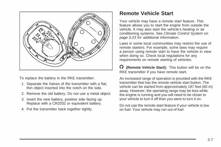
To replace the battery in the RKE transmitter:
1. Separate the halves of the transmitter with a flat,thin object inserted into the notch on the side.
2. Remove the old battery. Do not use a metal object.
3. Insert the new battery, positive side facing up.Replace with a CR2032 or equivalent battery.
4. Put the transmitter back together tightly.
Remote Vehicle StartYour vehicle may have a remote start feature. Thisfeature allows you to start the engine from outside thevehicle. It may also start the vehicle’s heating or airconditioning systems. See Climate Control System onpage 3-23 for additional information.
Laws in some local communities may restrict the use ofremote starters. For example, some laws may requirea person using remote start to have the vehicle in viewwhen doing so. Check local regulations for anyrequirements on remote starting of vehicles.
/ (Remote Vehicle Start): This button will be on theRKE transmitter if you have remote start.
An increased range of operation is provided with the RKEtransmitter that has the remote vehicle start button. Thevehicle can be started from approximately 197 feet (60 m)away. However, the operating range may be less whilethe engine is running and you will need to be closer toyour vehicle to turn it off than you were to turn it on.
Do not use the remote start feature if your vehicle is lowon fuel. Your vehicle may run out of fuel.
2-7

To start the engine using the remote start feature:
1. Aim the RKE transmitter at the vehicle.
2. Press and release the transmitter’s lock button,then immediately press and hold the remotevehicle start button for four seconds or until thevehicle’s turn signal lamps flash. The vehicle’s doorswill be locked.When the vehicle’s engine starts, the parking lampswill turn on and remain on while the engine isrunning.
3. If it is the first remote start since the vehicle hasbeen driven, repeat these steps, while the engine isstill running, to extend the engine running time by10 minutes. Remote start can be extended one time.
After entering the vehicle during a remote start, insertand turn the key to ON/RUN to drive the vehicle.
After a remote start, the engine will automatically shutoff after 10 minutes unless a time extension hasbeen done or the vehicle’s key is inserted into theignition switch and turned to ON/RUN.
The maximum number of remote starts between ignitioncycles with the key is two.
If the remote start procedure is used again before the first10 minute time frame has ended, the first 10 minutes willimmediately expire and the second 10 minute time framewill start.
After your vehicle’s engine has been started two timesusing the remote start button, the vehicle’s ignitionswitch must be turned to RUN and then back toLOCK/OFF using the key before the remote startprocedure can be used again.
To manually shut off the engine after a remote start:
• Aim the RKE transmitter at the vehicle and press theremote start button until the parking lamps turn off.
• Turn on the hazard warning flashers. See HazardWarning Flashers on page 3-6.
• Insert the vehicle’s key into the ignition switch andturn the switch to RUN and then back to LOCK/OFF.
The remote vehicle start feature will not operate if:
• The remote start system is disabled through the DIC.
• The vehicle’s key is in the ignition.
• The vehicle’s hood is open
• The hazard warning flashers are on.
• There is an emission control system malfunction.See Malfunction Indicator Lamp on page 3-40.
• The engine coolant temperature is too high.
• The oil pressure is low.
• Two remote vehicle starts have already beenprovided.
2-8

Doors and Locks
Door Locks
{CAUTION:
Unlocked doors can be dangerous.• Passengers, especially children, can easily
open the doors and fall out of a movingvehicle. When a door is locked, the handlewill not open it. You increase the chanceof being thrown out of the vehicle in acrash if the doors are not locked. So, wearsafety belts properly and lock the doorswhenever you drive.
• Young children who get into unlockedvehicles may be unable to get out. A childcan be overcome by extreme heat and cansuffer permanent injuries or even deathfrom heat stroke. Always lock your vehiclewhenever you leave it.
• Outsiders can easily enter through anunlocked door when you slow down orstop your vehicle. Locking your doors canhelp prevent this from happening.
There are several ways to lock and unlock your vehicle.
To lock the driver’s door from the outside, turn thekey clockwise. To unlock the door, turn the keycounterclockwise.
You can also use the remote keyless entry transmitterto lock and unlock the doors.
From the inside, use the manual lock knobs on each dooror the power door lock switch to lock and unlock all doors.
Power Door Locks
The power door lockswitches are located onthe driver’s and frontpassenger’s door next tothe door handle.
Press the top of the switch to unlock the doors. Pressthe bottom of the switch to lock the doors.
Driver’s side shown,Passenger’s side similar
2-9

Delayed LockingThis feature will delay the actual locking of the doorsand liftgate when the power door lock switch or remotekeyless entry transmitter is used to lock the vehicle.
If any door is open when locking the vehicle, threechimes will sound signaling that the delayed lockingfeature is active. Five seconds after the last dooris closed, all of the doors and liftgate will lock. The turnsignal lamps will flash to indicate that the doors havebeen locked. To cancel the delay and lock thedoors immediately, press the lock button a second time.
If the key is in the ignition this feature will not lockthe doors.
If your vehicle has a Driver Information Center (DIC),you can disable this function. See DIC VehiclePersonalization on page 3-54.
Automatic Door LockIf your vehicle has power door locks, the doors willautomatically lock when the shift lever is moved out ofPARK (P) for a vehicle with an automatic transmission.For a vehicle with a manual transmission, the speedmust be greater than 5 mph (8 km/h).
The automatic door locking feature cannot be disabled.
Programmable Automatic DoorUnlockYour vehicle will automatically unlock all doors when theshift lever is moved into PARK (P) for a vehicle withan automatic transaxle, and when the ignition is turnedoff for a vehicle with a manual transaxle.
If your vehicle has a Driver Information Center (DIC),the doors can be programmed to automaticallyunlock several ways for vehicles with an automatictransaxle. See DIC Vehicle Personalization onpage 3-54 for more information.
2-10
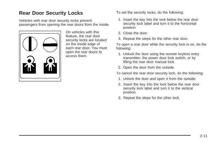
Rear Door Security LocksVehicles with rear door security locks preventpassengers from opening the rear doors from the inside.
On vehicles with thisfeature, the rear doorsecurity locks are locatedon the inside edge ofeach rear door. You mustopen the rear doors toaccess them.
To set the security locks, do the following:
1. Insert the key into the lock below the rear doorsecurity lock label and turn it to the horizontalposition.
2. Close the door.
3. Repeat the steps for the other rear door.
To open a rear door while the security lock is on, do thefollowing:
1. Unlock the door using the remote keyless entrytransmitter, the power door lock switch, or bylifting the rear door manual lock.
2. Open the door from the outside.
To cancel the rear door security lock, do the following:
1. Unlock the door and open it from the outside.
2. Insert the key into the lock below the rear doorsecurity lock label and turn it to the verticalposition.
3. Repeat the steps for the other lock.
2-11

Lockout ProtectionIf you press the power door lock switch when the key isin the ignition and any door is open, all the doors willlock and the driver’s door will unlock. Be sure to removethe key from the ignition when locking your vehicle.
The lockout protection can be overridden by pressingand holding the power door lock in the lock position forthree seconds.
Rear Side Cargo DoorThe rear side cargo doors can be opened by pressingthe buttons located on the driver and passenger sides ofthe instrument panel, or by using the Remote KeylessAccess (RKE) transmitter. See Instrument PanelOverview on page 3-4, and Remote Keyless Entry (RKE)System Operation on page 2-5 for more information.
To use the buttons on the instrument panel, the driverside door must be unlocked.
Push the door to close.
LiftgateTo lock the liftgate from the outside, press the lockbutton on the Remote Keyless Entry (RKE) transmitter.To unlock the liftgate with the RKE, press the unlockbutton twice within five seconds. For more information,see Remote Keyless Entry (RKE) System Operationon page 2-5. You can also use the power doorlock switch to lock and unlock the liftgate.
Open the liftgate by pressing the touchpad located inthe handle above the license plate. Once slightlyopened, the liftgate will rise by itself. Lamps in the rearof the vehicle will come on, illuminating the rearcargo area, unless the dome lamp lever is in the offposition. For more information, see Dome Lampon page 3-19.
Notice: If you open the liftgate without checking foroverhead obstructions such as a garage door,you could damage the liftgate or the liftgate glass.Always check to make sure the area above andbehind the liftgate is clear before opening it.
2-12
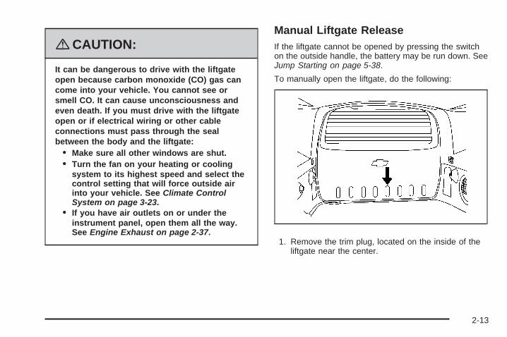
{CAUTION:
It can be dangerous to drive with the liftgateopen because carbon monoxide (CO) gas cancome into your vehicle. You cannot see orsmell CO. It can cause unconsciousness andeven death. If you must drive with the liftgateopen or if electrical wiring or other cableconnections must pass through the sealbetween the body and the liftgate:
• Make sure all other windows are shut.• Turn the fan on your heating or cooling
system to its highest speed and select thecontrol setting that will force outside airinto your vehicle. See Climate ControlSystem on page 3-23.
• If you have air outlets on or under theinstrument panel, open them all the way.See Engine Exhaust on page 2-37.
Manual Liftgate ReleaseIf the liftgate cannot be opened by pressing the switchon the outside handle, the battery may be run down. SeeJump Starting on page 5-38.
To manually open the liftgate, do the following:
1. Remove the trim plug, located on the inside of theliftgate near the center.
2-13

2. Locate the releaselever on the latch.
The lever is located about three inches (7.62 cm)behind the trim in the access hole.
3. Insert a tool into the access hole.
Push the release leverrearward.
4. The liftgate will unlatch when the lever is pushedrearward. Push the liftgate to open.
5. Reinstall the trim plug.
2-14

Windows
{CAUTION:
Leaving children, helpless adults, or pets in avehicle with the windows closed is dangerous.They can be overcome by the extreme heatand suffer permanent injuries or even deathfrom heat stroke. Never leave a child, ahelpless adult, or a pet alone in a vehicle,especially with the windows closed in warm orhot weather.
2-15

Power Windows
{CAUTION:
Leaving children, helpless adults, or pets in avehicle with the windows closed is dangerous.They can be overcome from extreme heat inwarm or hot weather and suffer permanentinjuries or even death from heat stroke.
Leaving children in a vehicle with the ignitionkey is dangerous for many reasons, children orothers could be badly injured or even killed.They could operate the power windows or othercontrols or even make the vehicle move. Thewindows will function with the keys in theignition and they could be seriously injured orkilled if caught in the path of a closing window.Do not leave keys in a vehicle with children.
When there are children in the rear seat use thewindow lockout button to prevent unintentionaloperation of the windows.
Passenger Vehicle shown, HHR Panel similar
HHR SS shown
2-16

Passenger Vehicle and HHR PanelThe window switches are located on the center console.The passenger vehicle has switches for each rearwindow located on each rear door.
To open a window, press the bottom of the switch.To close a window, press the top of the switch.
The power windows operate when the ignition is RUNor ACC (Accessory), or while in Retained AccessoryPower (RAP). See Retained Accessory Power (RAP) onpage 2-25.
HHR SSThe power window controls are located on each of theside doors. The driver’s door also has switches thatcontrol the passenger and rear windows.
Press the switch to lower the window. Pull up on thefront edge of the switch to raise the window.
The power windows work when the ignition has beenturned to ACCESSORY or RUN or when RetainedAccessory Power (RAP) is active. See RetainedAccessory Power (RAP) on page 2-25.
Express-Down WindowThe driver’s window switch has an express-downfeature that allows the window to be lowered withoutholding the switch. The switch is labeled AUTO. Pressthe switch part way, and the driver’s window will
open a small amount. Press the switch down all theway, release it, and the window will go downautomatically.
To stop the window while it is lowering, press andrelease the top of, or pull up on the switch.
Window Lockout
o (Window Lockout): Your vehicle has a lockoutfeature to prevent rear seat passengers from operatingthe windows. Press the lockout button, located withthe power window switches, to turn the feature on andoff. When the red band on the button is showing,the lockout feature is off.
Sun VisorsTo block out glare, swing down the visor(s). The sunvisors can also be detached from the center mount andswung out to cover the side windows. They can alsobe slid along the rod to cover different areas of the frontwindow.
Visor Vanity MirrorsYour vehicle has visor vanity mirrors. Swing down thesun visor and lift the cover to expose the mirror.
2-17
Theft-Deterrent SystemsVehicle theft is big business, especially in some cities.Although your vehicle has a number of theft-deterrentfeatures, we know that nothing we put on it can make itimpossible to steal.
Content Theft-Deterrent
Your vehicle may have acontent theft-deterrentalarm system. If yourvehicle has RemoteKeyless Entry (RKE), thenit has contenttheft-deterrent.
Arming the SystemWith the ignition off, you can arm the system by:
• Pressing the RKE transmitter lock button.
• Pressing the power door lock switch while thedriver’s door is open.
The system will arm after either of these things occur:
• Thirty seconds after all the doors are closed.
• Sixty seconds with any door open.
If you press the lock button on the transmitter a secondtime while all the doors are closed, the system willarm immediately. The system will still arm in 60 secondsif a door is open. When the open door is closed, it willalso become armed.
The security light will turn on to indicate that arming hasbeen initiated. Once the system is armed, the securitylight will flash once every three seconds.
If the security light is flashing twice per second, thismeans that a door is open.
If you do not want to arm the system, you may lock thecar with the manual lock knobs on the doors.
Disarming the SystemTo disarm the system:
• Press the RKE transmitter unlock button.
• Turn the ignition on.
Once the system is disarmed, the security light will stopflashing.
2-18

How the System Alarm is ActivatedIf the system is armed, it can be activated by either:
• Opening the driver’s door or tailgate. This will causea ten second pre-alarm chirp followed by athirty second full alarm of horn and lights.
• Opening any other door. This will immediately causea full alarm of horn and lights for thirty seconds.
When an alarm event has finished, the system willre-arm itself automatically.
How to Turn Off the System AlarmTo turn off the system alarm:
• Press the lock button on the RKE transmitter. Thesystem will then re-arm itself.
• Press the unlock button on the RKE transmitter.This will also disarm the system.
• Insert the key in the ignition and turn it on. This willalso disarm the system.
How to Detect a Tamper ConditionIf you hear three chirps when you press the unlock or lockbuttons on the RKE transmitter, it means that the contenttheft security system alarm was previously activated.
PASS-Key® III+The PASS-Key® III+ system operates on a radiofrequency subject to Federal CommunicationsCommission (FCC) Rules and with Industry Canada.
This device complies with Part 15 of the FCC Rules.Operation is subject to the following two conditions:
1. This device may not cause harmful interference.
2. This device must accept any interference received,including interference that may cause undesiredoperation.
This device complies with RSS-210 of Industry Canada.Operation is subject to the following two conditions:
1. This device may not cause interference.
2. This device must accept any interference received,including interference that may cause undesiredoperation of the device.
Changes or modifications to this system by other thanan authorized service facility could void authorization touse this equipment.
PASS-Key® III+ uses a radio frequency transponder inthe key that matches a decoder in your vehicle.
2-19

PASS-Key® III+ OperationYour vehicle has PASS-Key® III+ (PersonalizedAutomotive Security System) theft-deterrent system.PASS-Key® III+ is a passive theft-deterrent system.
The system is automatically armed when the keyis removed from the ignition.
You do not have to manually arm or disarm the system.
The security light will come on if there is a problemwith arming or disarming the theft-deterrent system.
When the PASS-Key® III+ system senses that someoneis using the wrong key, it prevents the vehicle fromstarting. Anyone using a trial-and-error method to startthe vehicle will be discouraged because of the highnumber of electrical key codes.
When trying to start the vehicle if the engine does notstart and the security light comes on, there may bea problem with your theft-deterrent system. Turnthe ignition off and try again.
If the engine still does not start, and the key appears to beundamaged, try another ignition key. At this time, youmay also want to check the fuse, see Fuses and CircuitBreakers on page 5-119. If the engine still does not startwith the other key, your vehicle needs service.
If your vehicle does start, the first key may be faulty. Seeyour dealer/retailer who can service the PASS-Key® III+to have a new key made. In an emergency, contactRoadside Assistance. See Roadside Assistance Programon page 7-6, for more information.
It may be possible for the PASS-Key® III+ decoder to“learn” the transponder value of a new or replacementkey. Up to 10 keys may be programmed for the vehicle.The following procedure is for programming additionalkeys only. If all the currently programmed keys arelost or do not operate, you must see your dealer/retaileror a locksmith who can service PASS-Key® III+ tohave keys made and programmed to the system.
See your dealer/retailer or a locksmith who can servicePASS-Key® III+ to get a new key blank that is cutexactly as the ignition key that operates the system.
To program the new key:
1. Verify that the new key has a 1 stamped on it.
2. Insert the already programmed key in the ignitionand start the engine. If the engine will not start, seeyour dealer/retailer for service.
3. After the engine has started, turn the key toLOCK/OFF, and remove the key.
2-20

4. Insert the key to be programmed and turn it to theON/RUN position within five seconds of the originalkey being turned to the LOCK/OFF position.The security light will turn off once the key hasbeen programmed.
5. Repeat Steps 1 through 4 if additional keys are tobe programmed.
If you are ever driving and the security light comes onand stays on, you may be able to restart your engine ifyou turn it off. Your PASS-Key® III+ system, however,is not working properly and must be serviced byyour dealer/retailer. Your vehicle is not protected by thePASS-Key® III+ system at this time.
If you lose or damage your PASS-Key® III+ key, seeyour dealer/retailer or a locksmith who can servicePASS-Key® III+ to have a new key made.
Do not leave the key or device that disarms ordeactivates the theft deterrent system in the vehicle.
Starting and Operating YourVehicle
New Vehicle Break-InNotice: Your vehicle does not need an elaboratebreak-in. But it will perform better in the long run ifyou follow these guidelines:
• Do not drive at any one constant speed, fast orslow, for the first 500 miles (805 km). Do notmake full-throttle starts. Avoid downshifting tobrake or slow the vehicle.
• Avoid making hard stops for the first 200 miles(322 km) or so. During this time the new brakelinings are not yet broken in. Hard stopswith new linings can mean premature wear andearlier replacement. Follow this breaking-inguideline every time you get new brake linings.
• Do not tow a trailer during break-in. See Towinga Trailer (Manual Transaxle) on page 4-34 orTowing a Trailer (Automatic Transaxle) onpage 4-34 for the trailer towing capabilities ofyour vehicle and more information.
Following break-in, engine speed and load can begradually increased.
2-21

Ignition Positions
With the key in the ignitionswitch, you can turn it tofour different positions.
In order to shift out of PARK (P), ignition must be in theON/RUN or ACC/ACCESSORY and the regular brakepedal must be applied.
Notice: Using a tool to force the key from theignition switch could cause damage or break thekey. Use the correct key and turn the key only withyour hand. Make sure the key is all the way in. Ifnone of this works, then your vehicle needs service.
9 (LOCK/OFF): This position locks your steeringcolumn. It is a theft-deterrent feature. You will only beable to remove your key when the ignition is turnedto LOCK/OFF.
If the steering wheel is locked, move it from right to leftand turn the key to ACC/ACCESSORY. If none ofthis works, then your vehicle needs service.
If you have an automatic transmission, the ignitionswitch cannot be turned to LOCK/OFF unless the shiftlever is in PARK (P).
If you have a manual transmission, the ignition switchcan be turned to LOCK/OFF in any shift lever position.
2-22

{CAUTION:
If you have a manual transmission removingthe key from the ignition switch will lock thesteering column and result in a loss of abilityto steer the vehicle. This could cause acollision. If you need to turn the engine offwhile the vehicle is moving, turn the key toACC/ACCESSORY.
ACC (ACC/ACCESSORY): This position operatessome of your electrical accessories. It unlocks thesteering wheel and ignition.
R (ON/RUN): This is the position the switch returns toafter you start your engine and release the switch.The switch stays in the ON/RUN position whenthe engine is running. But even when the ignition is notrunning, you can use ON/RUN to operate yourelectrical accessories and to display some warning andindicator lights.
The battery could be drained if you leave the key in theACC/ACCESSORY or ON/RUN position with the engineoff. You may not be able to start your vehicle if the batteryis allowed to drain for an extended period of time.
/ (START): This position starts the engine. When theengine starts, release the key. The ignition switchwill return to ON/RUN for normal driving.
A warning tone will sound if you open the driver’s doorwhile in LOCK/OFF or ACC/ACCESSORY, whenthe key has not been removed from the ignition.
Key In the IgnitionNever leave your vehicle with the keys inside, as it is aneasy target for joy riders or thieves. If you leave thekey in the ignition and park your vehicle, a chimewill sound, when you open the driver’s door. Alwaysremember to remove your key from the ignition and takeit with you. This will lock your ignition and transmission.Also, always remember to lock the doors.
The battery could be drained if you leave the key in theignition while your vehicle is parked. You may not beable to start your vehicle after it has been parked for anextended period of time.
2-23

Column Lock ReleaseFor vehicles with an automatic transmission, thefollowing procedure allows the ignition to be turned toLOCK/OFF and ignition key removal in case of adead battery or low voltage battery.
1. Make sure the shift lever is in PARK (P).
2. Remove the cover from the bottom of the steeringcolumn.
3. Locate the plunger.
4. Press and hold the plunger toward the driver’s doorwhile turning the ignition key to LOCK/OFF.Remove the key.
Have your vehicle serviced at your dealer/retailer assoon as possible.
2-24

Retained Accessory Power (RAP)These vehicle accessories may be used for up to10 minutes after the engine is turned off.
• Audio System
• Power Windows
• Sunroof
The power windows and sunroof will continue to workfor up to 10 minutes or until any door is opened.The radio will work when the key is in ON/RUN orACC/ACCESSORY. Once the key is turned fromON/RUN to OFF/LOCK, the radio will continue to workfor 10 minutes or until the driver’s door is opened.
Starting the EnginePlace the transmission in the proper gear.
Automatic TransmissionMove the shift lever to PARK (P) or NEUTRAL (N). Theengine will not start in any other position -- this is asafety feature. To restart when you are already moving,use NEUTRAL (N) only.
Notice: Do not try to shift to PARK (P) if yourvehicle is moving. If you do, you could damage thetransmission. Shift to PARK (P) only when yourvehicle is stopped.
Manual TransmissionThe shift lever should be in neutral position and theparking brake engaged. Hold the clutch pedal down tothe floor and start the engine. Your vehicle will notstart if the clutch pedal is not all the way down. That isa safety feature.
2-25
Starting Procedure1. With your foot off the accelerator pedal, turn the
ignition key to START. When the engine starts,let go of the key. The idle speed will go down asyour engine gets warm. Do not race the engineimmediately after starting it. Operate the engine andtransmission gently to allow the oil to warm upand lubricate all moving parts.Your vehicle has a Computer-Controlled CrankingSystem. This feature assists in starting theengine and protects components. If the ignition keyis turned to the START position, and thenreleased when the engine begins cranking, theengine will continue cranking for a few seconds oruntil the vehicle starts. If the engine does notstart and the key is held in START for manyseconds, cranking will be stopped after 15 secondsto prevent cranking motor damage. To preventgear damage, this system also prevents cranking ifthe engine is already running. Engine crankingcan be stopped by turning the ignition switchto ACC/ACCESSORY or LOCK/OFF.
Notice: Cranking the engine for long periods oftime, by returning the key to the START positionimmediately after cranking has ended, can overheatand damage the cranking motor, and drain thebattery. Wait at least 15 seconds between each try,to let the cranking motor cool down.
2. If the engine does not start after 5-10 seconds,especially in very cold weather (below 0°F or −18°C),it could be flooded with too much gasoline. Trypushing the accelerator pedal all the way to the floorand holding it there as you hold the key in START forup to a maximum of 15 seconds. Wait at least15 seconds between each try, to allow the crankingmotor to cool down. When the engine starts, let go ofthe key and accelerator. If the vehicle starts brieflybut then stops again, do the same thing. This clearsthe extra gasoline from the engine. Do not race theengine immediately after starting it. Operate theengine and transmission gently until the oil warms upand lubricates all moving parts.
Notice: The engine is designed to work with theelectronics in your vehicle. If you add electricalparts or accessories, you could change the way theengine operates. Before adding electrical equipment,check with your dealer/retailer. If you do not, yourengine might not perform properly. Any resultingdamage would not be covered by your vehicle’swarranty.
2-26
Engine Coolant HeaterThe engine coolant heater, if available, can help in coldweather conditions at or below 0°F (−18°C) for easierstarting and better fuel economy during engine warm-up.Plug in the coolant heater at least four hours beforestarting your vehicle. An internal thermostat in theplug-end of the cord may exist which will preventengine coolant heater operation at temperaturesabove 0°F (−18°C).
To Use the Engine Coolant Heater1. Turn off the engine.
2. Open the hood and unwrap the electrical cord. Forthe 2.2L and 2.4L engine, the electrical cord islocated on the passenger’s side of the vehicle nearthe headlamp and the radiator.
3. Plug it into a normal, grounded 110-volt AC outlet.
{CAUTION:
Plugging the cord into an ungrounded outletcould cause an electrical shock. Also, thewrong kind of extension cord could overheatand cause a fire. You could be seriouslyinjured. Plug the cord into a properly groundedthree-prong 110-volt AC outlet. If the cord willnot reach, use a heavy-duty three-prongextension cord rated for at least 15 amps.
4. Before starting the engine, be sure to unplug andstore the cord as it was before to keep it awayfrom moving engine parts. If you do not, it could bedamaged.
How long should you keep the coolant heater pluggedin? The answer depends on the outside temperature, thekind of oil you have, and some other things. Insteadof trying to list everything here, we ask that you contacta dealer/retailer in the area where you will be parkingyour vehicle. The dealer/retailer can give you thebest advice for that particular area.
2-27

Automatic Transmission OperationIf your vehicle has an automatic transmission, theshift lever is located on the console between the seats.
There are several differentpositions for the automatictransmission.
PARK (P): This position locks your front wheels. It isthe best position to use when you start your enginebecause your vehicle cannot move easily.
{CAUTION:
It is dangerous to get out of your vehicle if theshift lever is not fully in PARK (P) with theparking brake firmly set. Your vehicle can roll.
Do not leave your vehicle when the engine isrunning unless you have to. If you have left theengine running, the vehicle can movesuddenly. You or others could be injured. Tobe sure your vehicle will not move, even whenyou are on fairly level ground, always set yourparking brake and move the shift lever toPARK (P). See Shifting Into PARK (P)(Automatic Transmission) on page 2-34. If youare pulling a trailer, see Towing a Trailer(Manual Transaxle) on page 4-34 or Towing aTrailer (Automatic Transaxle) on page 4-34.
2-28
Make sure the shift lever is fully in PARK (P) beforestarting the engine. Your vehicle has an automatictransaxle shift lock control system. You have to fullyapply your regular brakes first and then press the shiftlever button before you can shift from PARK (P)when the ignition key is in RUN. If you cannot shift outof PARK (P), ease pressure on the shift lever andpush the shift lever all the way into PARK (P) as youmaintain brake application. Then press the shiftlever button and then move the shift lever into anothergear. See Shifting Out of PARK (P) (AutomaticTransmission) on page 2-36.
REVERSE (R): Use this gear to back up.
Notice: Shifting to REVERSE (R) while your vehicleis moving forward could damage the transmission.The repairs would not be covered by your warranty.Shift to REVERSE (R) only after your vehicle isstopped.
To rock your vehicle back and forth to get out of snow,ice, or sand without damaging your transmission,see If Your Vehicle is Stuck in Sand, Mud, Ice, or Snowon page 4-26.
NEUTRAL (N): In this position, your engine does notconnect with the wheels. To restart when you arealready moving, use NEUTRAL (N) only. Also, useNEUTRAL (N) when your vehicle is being towed.
{CAUTION:
Shifting into a drive gear while the engine isrunning at high speed is dangerous. Unlessyour foot is firmly on the brake pedal, yourvehicle could move very rapidly. You couldlose control and hit people or objects. Do notshift into a drive gear while your engine isrunning at high speed.
Notice: Shifting out of PARK (P) or NEUTRAL (N)with the engine running at high speed may damagethe transmission. The repairs would not becovered by your warranty. Be sure the engine is notrunning at high speed when shifting your vehicle.
2-29

DRIVE (D): This position is for normal driving with theautomatic transmission. It provides the best fueleconomy for your vehicle. If you need more power forpassing, and you are:
• Going less than about 35 mph (55 km/h), push youraccelerator pedal about halfway down.
• Going about 35 mph (55 km/h), push youraccelerator all the way down.
Downshifting the transmission in slippery road conditionscould result in skidding, see “Skidding” under Loss ofControl on page 4-16.
INTERMEDIATE (I): This position is also used fornormal driving. However, it reduces vehicle speedwithout using your brakes for slight downgrades wherethe vehicle would otherwise accelerate due tosteepness of grade. If constant upshifting ordownshifting occurs while driving up steep hills, thisposition can be used to prevent repetitive types of shifts.
You might choose INTERMEDIATE (I) instead ofDRIVE (D) when driving on hilly, winding roads andwhen towing a trailer, so that there is less shiftingbetween gears.
LOW (L): This position reduces vehicle speed morethan INTERMEDIATE (I) without actually usingyour brakes. You can use it on very steep hills, or indeep snow or mud. If the shift lever is put in LOW (L),the transmission will not shift into LOW (L) until thevehicle is going slowly enough.
Notice: Spinning the tires or holding the vehicle inone place on a hill using only the acceleratorpedal may damage the transmission. The repair willnot be covered by your warranty. If you are stuck,do not spin the tires. When stopping on a hill,use the brakes to hold the vehicle in place.
2-30

Manual Transmission Operation
This is the shift pattern.
Here is how to operate the manual transmission:
FIRST (1): Press the clutch pedal down and shift intoFIRST (1). Then, slowly let up on the clutch pedal downas you press the accelerator pedal down.
You can shift into FIRST (1) when you are going lessthan 20 mph (32 km/h). If you have come to a completestop and it is hard to shift into FIRST (1), put the shiftlever in NEUTRAL and let up on the clutch pedal. Pressthe clutch pedal back down. Then shift into FIRST (1).
SECOND (2): Press the clutch pedal down as you let upon the accelerator pedal and shift into SECOND (2).Then, slowly let up on the clutch pedal as you press theaccelerator pedal.
THIRD (3), FOURTH (4) and FIFTH (5): Shift intoTHIRD (3), FOURTH (4) and FIFTH (5) the same wayyou do for SECOND (2). Slowly let up on the clutchpedal as you press the accelerator pedal down.
To stop, let up on the accelerator pedal and press thebrake pedal. Just before the vehicle stops, pressthe clutch pedal down and the brake pedal, and shift toNEUTRAL.
NEUTRAL: Use this position when you start or idleyour engine.
2-31

REVERSE (R): To back up, press down the clutchpedal and shift into REVERSE (R). Let up on the clutchpedal slowly while pressing the accelerator pedal.
Notice: Shifting to REVERSE (R) while your vehicleis moving forward could damage the transmission.The repairs would not be covered by your warranty.Shift to REVERSE (R) only after your vehicle isstopped.
Also, use REVERSE (R), along with the parking brake,for parking your vehicle.
Shift Speeds
{CAUTION:
If you skip a gear when you downshift, youcould lose control of your vehicle. You couldinjure yourself or others. Do not shift downmore than one gear at a time when youdownshift.
Up-Shift Light
If you have a manualtransmission, you mayhave an up-shift light. Thislight will show you whento shift to the nexthigher gear for the bestfuel economy.
When this light comes on, you can shift to the nexthigher gear if weather, road, and traffic conditions letyou. For the best fuel economy, accelerate slowlyand shift when the light comes on.
While you accelerate, it is normal for the light to go onand off if you quickly change the position of theaccelerator. Ignore the light when you downshift.
2-32
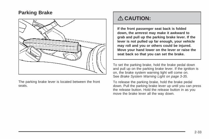
Parking Brake
The parking brake lever is located between the frontseats.
{CAUTION:
If the front passenger seat back is foldeddown, the armrest may make it awkward tograb and pull up the parking brake lever. If thelever is not pulled up far enough, your vehiclemay roll and you or others could be injured.Move your hand lower on the lever or raise theseat back so that you can set the brake.
To set the parking brake, hold the brake pedal downand pull up on the parking brake lever. If the ignition ison, the brake system warning light will come on.See Brake System Warning Light on page 3-35.
To release the parking brake, hold the brake pedaldown. Pull the parking brake lever up until you can pressthe release button. Hold the release button in as youmove the brake lever all the way down.
2-33

If you forget to release your parking brake, a chime willsound and a warning message will be displayedwhen the parking brake is applied and the vehicle ismoving faster than 5 mph (8 kph). See DIC Warningsand Messages on page 3-48.
Notice: Driving with the parking brake on canoverheat the brake system and cause prematurewear or damage to brake system parts. Make surethat the parking brake is fully released and the brakewarning light is off before driving.
Shifting Into PARK (P) (AutomaticTransmission)
{CAUTION:
It can be dangerous to get out of your vehicleif the shift lever is not fully in PARK (P) withthe parking brake firmly set. Your vehicle canroll. If you have left the engine running, thevehicle can move suddenly.
CAUTION: (Continued)
CAUTION: (Continued)
You or others could be injured. To be sureyour vehicle will not move, even when you areon fairly level ground, use the steps thatfollow. If you are pulling a trailer, see Towing aTrailer (Manual Transaxle) on page 4-34 orTowing a Trailer (Automatic Transaxle) onpage 4-34.
To shift into PARK (P), do the following:
1. Hold the brake pedal down with your right foot andset the parking brake. See Parking Brake onpage 2-33 for more information.
2. Move the shift lever into PARK (P) by holding in thebutton on the shift lever and pushing the lever allthe way toward the front of the vehicle.
3. Turn the ignition key to LOCK/OFF.
4. Remove the key and take it with you. If you canleave your vehicle with the key in your hand, yourvehicle is in PARK (P).
2-34

Leaving Your Vehicle With the EngineRunning (Automatic Transmission)
{CAUTION:
It can be dangerous to leave your vehicle withthe engine running. Your vehicle could movesuddenly if the shift lever is not fully inPARK (P) with the parking brake firmly set.And, if you leave the vehicle with the enginerunning, it could overheat and even catch fire.You or others could be injured. Do not leaveyour vehicle with the engine running.
If you have to leave your automatic transmission vehiclewith the engine running, be sure your vehicle is inPARK (P) and your parking brake is firmly set beforeyou leave it. After you have moved the shift leverinto PARK (P), hold the regular brake pedal down. Then,see if you can move the shift lever away from PARK (P)without first pulling it toward you. If you can, it meansthat the shift lever was not fully locked into PARK (P).
Torque Lock (Automatic Transmission)If you are parking on a hill and you do not shift intoPARK (P) properly, the weight of the vehicle may put toomuch force on the parking pawl in the transmission.You may find it difficult to pull the shift lever out ofPARK (P). This is called “torque lock.” To prevent torquelock, set the parking brake and then shift into PARK (P)properly before you leave the driver’s seat. To findout how, see Shifting Into PARK (P) (AutomaticTransmission) on page 2-34.
When you are ready to drive, move the shift lever out ofPARK (P) before you release the parking brake.
If torque lock does occur, you may need to have anothervehicle push yours a little uphill to take some of thepressure from the parking pawl in the transmission, soyou can pull the shift lever out of PARK (P).
2-35
Shifting Out of PARK (P) (AutomaticTransmission)This vehicle is equipped with an electronic shift lockrelease system. The shift lock release is designed to:
• Prevent ignition key removal unless the shiftlever is in PARK (P) with the shift lever button fullyreleased, and
• Prevent movement of the shift lever out of PARK (P)unless the ignition is in ON/RUN orACC/ACCESSORY and the regular brake pedal isapplied.
The shift lock release is always functional except in thecase of a an uncharged or low voltage (less than 9 volt)battery.
If your vehicle has an uncharged battery or a batterywith low voltage, try charging or jump starting thebattery. See Jump Starting on page 5-38 for moreinformation.
To shift out of PARK (P):
1. Apply the brake pedal.
2. Then press the shift lever button.
3. Move the shift lever to the desired position.
If you still are unable to shift out of PARK (P):
1. Fully release the shift lever button.
2. While holding down the brake pedal, press the shiftlever button again.
3. Move the shift lever to the desired position.
If you still cannot move the shift lever from PARK (P),consult your dealer or a professional towing service.
Parking Your Vehicle (ManualTransmission)Before leaving your vehicle, fully press the clutch pedaldown, move the shift lever into REVERSE (R), andfirmly apply the parking brake. Once the shift lever hasbeen placed in REVERSE (R) with the clutch pedalpressed down, you can turn the ignition key to LOCK,remove the key and release the clutch pedal. SeeManual Transmission Operation on page 2-31.
2-36
Parking Over Things That Burn
{CAUTION:
Things that can burn could touch hot exhaustparts under your vehicle and ignite. Do notpark over papers, leaves, dry grass, or otherthings that can burn.
Engine Exhaust
{CAUTION:
Engine exhaust can kill. It contains the gascarbon monoxide (CO), which you cannot see orsmell. It can cause unconsciousness and death.
You might have exhaust coming in if:• The exhaust system sounds strange or
different.• Your vehicle gets rusty underneath.• Your vehicle was damaged in a collision.• Your vehicle was damaged when driving
over high points on the road or over roaddebris.
• Repairs were not done correctly.• Your vehicle or the exhaust system has
been modified improperly.
If you ever suspect exhaust is coming into yourvehicle:
• Drive it only with all the windows down toblow out any CO; and
• Have your vehicle fixed immediately.
2-37

Running the Engine While ParkedIt is better not to park with the engine running. But if youever have to, here are some things to know.
{CAUTION:
Idling the engine with the climate controlsystem off could allow dangerous exhaust intoyour vehicle. See the earlier caution underEngine Exhaust on page 2-37.
Also, idling in a closed-in place can let deadlycarbon monoxide (CO) into your vehicle even ifthe climate control fan is at the highest setting.One place this can happen is a garage.Exhaust — with CO — can come in easily.NEVER park in a garage with the enginerunning.
Another closed-in place can be a blizzard. SeeWinter Driving on page 4-22.
{CAUTION:
It can be dangerous to get out of your vehicleif the shift lever is not fully in PARK (P) withthe parking brake firmly set. Your vehicle canroll. Do not leave your vehicle when the engineis running unless you have to. If you have leftthe engine running, the vehicle can movesuddenly. You or others could be injured. Tobe sure your vehicle will not move, even whenyou are on fairly level ground, always set theparking brake and move the shift lever toPARK (P).
Follow the proper steps to be sure your vehicle will notmove. See Shifting Into PARK (P) (AutomaticTransmission) on page 2-34.
If you are parking on a hill and if you are pulling atrailer, also see Towing a Trailer (Manual Transaxle) onpage 4-34 or Towing a Trailer (Automatic Transaxle)on page 4-34.
2-38

Mirrors
Manual Rearview MirrorWhen you are sitting in a comfortable driving position,adjust the mirror so you can see clearly behind yourvehicle. Grip the mirror in the center to move it upor down and side to side. The day/night adjustmentallows you to adjust the mirror to avoid glare from thelamps behind you. Push the tab forward for daytime useand pull it for nighttime use.
The mirror may have lights located on the bottom of themirror. Press the button next to each light to turn iton or off.
Automatic Dimming Rearview Mirrorwith OnStar® and CompassYour vehicle may have an automatic dimming rearviewmirror with OnStar®, compass, and map lights. Thecompass automatically calibrates, or sets the drivingdirection, as the vehicle is driven. The automaticdimming feature enables the rearview mirror to sensenighttime glare from vehicle headlamps from behind andautomatically dim to reduce the glare to a safe level.The automatic dimming feature turns on each time thevehicle is started.
Press the buttons located at the bottom of the mirror toturn the map lights on or off.
There are three additional buttons for the OnStar®
system. See your dealer/retailer for more information onthe system and how to subscribe to OnStar®. SeeOnStar® in the Index for more information.
O (On/Off): This is the on/off button for the automaticdimming feature.
Automatic Dimming Mirror OperationThe automatic dimming mirror function is turnedon automatically each time the ignition is started. Tooperate the automatic dimming mirror, do the following:
1. Make sure the green indicator light, located tothe left of the on/off button, is on. If it is not,press and hold the on/off button until the green lightcomes on.
2. Turn off the automatic dimming mirror function bypressing and holding the on/off button until thegreen indicator light turns off.
Compass OperationPress the on/off button to turn the compass on or off.
The direction the vehicle is facing appears on the mirror.
2-39

Compass CalibrationIf a compass direction, (N for North for example) does notappear, there may be a strong magnetic field interferingwith the compass. This can be caused by a magneticantenna mount, note pad holder, or similar objects. If theword CAL appears in the compass window, the compassmay need to be reset or calibrated.
To calibrate the compass, do the following:
1. Make sure CAL is displayed on the mirror. If not,press and hold the on/off button until CAL displays.
2. While CAL is displayed, drive the vehicle in circlesat 5 mph (8 km/h) or less until a direction appearson the mirror.
Compass VarianceCompass variance is the difference between earth’smagnetic north and true geographic north. If the mirroris not adjusted for compass variance, the compasscould give false readings.
The mirror is set in zone eight upon leaving the factory.The compass must be adjusted to compensate forcompass variance if the vehicle is driven outsidezone eight.
To adjust for compass variance, do the following:
1. Find your current location and variance zonenumber on the following zone map.
2. Press and hold the compass button until a Z and azone number appears on the mirror.
3. Once the zone number appears on the mirror,press the compass button quickly until thecorrect zone number displays. If CAL appears inthe compass window, the compass may needcalibration. See “Compass Calibration” listedpreviously.
2-40
Cleaning the MirrorWhile cleaning the mirror, use a paper towel or similarmaterial dampened with glass cleaner. Do not sprayglass cleaner directly on the mirror as that may causethe liquid cleaner to enter the mirror housing.
Automatic Dimming Rearview Mirrorwith CompassYour vehicle may have an automatic dimming rearviewmirror with a compass and map lights. The compassfeature enables the mirror to sense nighttime glare fromvehicle headlamps from behind and automaticallydim to reduce the glare to a safe level. The automaticdimming feature turns on each time the vehicle isstarted. Press the buttons located at the bottom of themirror to turn the map lights on or off.
O (On/Off): This is the on/off button for the automaticdimming feature.
Automatic Dimming Mirror OperationThe automatic dimming mirror function is turnedon automatically each time the ignition is started. Tooperate the automatic dimming mirror, do the following:
1. Make sure the green indicator light, located to the leftof the on/off button, is on. If it’s not, press the on/offbutton until the green light comes on, indicating thatthe mirror is in automatic dimming mode.
2. Turn off the automatic dimming mirror function bypressing the on/off button until the green indicatorlight turns off.
Compass Operation
Y: This is the on/off button for the compass feature.
Press this button once to turn the compass on or off.
When the ignition and the compass feature are on, thecompass will show two character boxes for a fewseconds. After a few seconds, the mirror will display thecurrent compass direction.
2-41

Compass CalibrationIf after a few seconds the display does not show acompass direction, (N for North for example), there maybe a strong magnetic field interfering with the compass.Such interference may be caused by a magneticantenna mount, note pad holder, or similar object. If theletter C or CAL appears in the compass window, thecompass may need to be reset or calibrated.
To calibrate the compass, do the following:
1. Make sure CAL is displayed in the display. If CAL isnot displayed, press and hold the compass buttonuntil CAL is displayed.
2. While CAL is displayed, drive the vehicle in circlesat 5 mph (8 km/h) or less until the display reads adirection.
Compass VarianceCompass variance is the difference between earth’smagnetic north and true geographic north. If the mirroris not adjusted for compass variance, the compasscould give false readings.
The mirror is set in zone eight upon leaving the factory.It will be necessary to adjust the compass tocompensate for compass variance if the vehicle isdriven outside zone eight. Under certain circumstances,such as a long distance, cross-country trip, it will benecessary to adjust the compass variance.
To adjust for compass variance, do the following:
1. Find your current location and variance zonenumber on the following zone map.
2. Press and hold the compass button until a Z and azone number appear on the display.
2-42
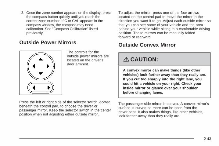
3. Once the zone number appears on the display, pressthe compass button quickly until you reach thecorrect zone number. If C or CAL appears in thecompass window, the compass may needcalibration. See “Compass Calibration” listedpreviously.
Outside Power Mirrors
The controls for theoutside power mirrors arelocated on the driver’sdoor armrest.
Press the left or right side of the selector switch locatedbeneath the control pad, to choose the driver orpassenger mirror. Keep the selector switch in the centerposition when not adjusting either outside mirror.
To adjust the mirror, press one of the four arrowslocated on the control pad to move the mirror in thedirection you want it to go. Adjust each outside mirror sothat you can see some of your vehicle and the areabehind your vehicle while sitting in a comfortable drivingposition. These mirrors can be manually foldedforward or rearward.
Outside Convex Mirror
{CAUTION:
A convex mirror can make things (like othervehicles) look farther away than they really are.If you cut too sharply into the right lane, youcould hit a vehicle on your right. Check yourinside mirror or glance over your shoulderbefore changing lanes.
The passenger side mirror is convex. A convex mirror’ssurface is curved so more can be seen from thedriver seat. It also makes things, like other vehicles,look farther away than they really are.
2-43

OnStar® System
OnStar uses several innovative technologies and liveadvisors to provide you with a wide range of safety,security, information, and convenience services. If yourairbags deploy, the system is designed to make anautomatic call to OnStar Emergency advisors who canrequest emergency services be sent to your location.If you lock your keys in the vehicle, call OnStar at1-888-4-ONSTAR and they can send a signal to unlockyour doors. If you need roadside assistance, pressthe OnStar button and they can contact RoadsideService for you.
OnStar service is provided to you subject to the OnStarTerms and Conditions. You may cancel your OnStarservice at any time by contacting OnStar. A completeOnStar Owner’s Guide and the OnStar Terms andConditions are included in the vehicle’s OnStarSubscriber glove box literature.
For more information, visit onstar.com or onstar.ca,contact OnStar at 1-888-4-ONSTAR (1-888-466-7827)or TTY 1-877-248-2080, or press the OnStar buttonto speak with an OnStar advisor 24 hours a day, 7 daysa week.
Not all OnStar features are available on all vehicles.To check if your vehicle is equipped to provide theservices described below, or for a full description ofOnStar services and system limitations, see the OnStarOwner’s Guide in your glove box or visit onstar.com.
OnStar ServicesFor new vehicles with OnStar, the Safe & Sound Plan,or the Directions & Connections Plan is included forone year from the date of purchase. You can extend thisplan beyond the first year, or upgrade to the Directions& Connections Plan. For more information, pressthe OnStar button to speak with an advisor. SomeOnStar services (such as Remote Door Unlock or StolenVehicle Location Assistance) may not be availableuntil you register with OnStar.
2-44
Available Services with Safe & Sound Plan• Automatic Notification of Airbag Deployment
• Advanced Automatic Crash Notification (AACN)(If equipped)
• Link to Emergency Services
• Roadside Assistance
• Stolen Vehicle Location Assistance
• AccidentAssist
• Remote Door Unlock/Vehicle Alert
• OnStar Vehicle Diagnostics
• GM Goodwrench® On Demand Diagnostics
• OnStar Hands-Free Calling with 30 complimentaryminutes
• OnStar Virtual Advisor (U.S. Only)
Available Services included with Directions& Connections Plan• All Safe and Sound Plan Services
• Driving Directions - Advisor delivered or OnStarTurn-by-Turn Navigation (If equipped)
• RideAssist
• Information and Convenience Services
OnStar Hands-Free CallingOnStar Hands-Free Calling allows eligible OnStarsubscribers to make and receive calls using voicecommands. Hands-Free Calling is fully integrated intothe vehicle, and can be used with OnStar Pre-PaidMinute Packages. Hands-Free Calling may alsobe linked to a Verizon Wireless service plan in the U.S.or a Bell Mobility service plan in Canada, dependingon eligibility. To find out more, refer to the OnStarOwner’s Guide in the vehicle’s glove box, visitwww.onstar.com or www.onstar.ca, or speak with anOnStar advisor by pressing the OnStar button or calling1-888-4-ONSTAR (1-888-466-7827).
OnStar Virtual AdvisorOnStar Virtual Advisor is a feature of OnStarHands-Free Calling that uses your minutes to accesslocation-based weather, local traffic reports, andstock quotes. By pressing the phone button and givinga few simple voice commands, you can browsethrough the various topics. See the OnStar Owner’sGuide for more information (Only available in thecontinental U.S.).
2-45

OnStar Steering Wheel ControlsYour vehicle may have a Talk/Mute button that can beused to interact with OnStar Hands-Free Calling.See Audio Steering Wheel Controls on page 3-79 formore information.
On some vehicles, you may have to hold the button fora few seconds and give the command “ONSTAR” toactivate the OnStar Hands-Free Calling.
On some vehicles, the mute button can be used to dialnumbers into voicemail systems, or to dial phoneextensions. See the OnStar Owner’s Guide for moreinformation.
How OnStar Service WorksYour vehicle’s OnStar system has the capability ofrecording and transmitting vehicle information. Thisinformation is automatically sent to an OnStar CallCenter at the time of an OnStar button press,Emergency button press or if your airbags or AACNsystem deploys. The vehicle information usually includesyour GPS location and, in the event of a crash,additional information regarding the accident that yourvehicle has been involved in (e.g. the direction fromwhich your vehicle was hit). When you use the VirtualAdvisor feature of OnStar Hands-Free Calling, yourvehicle also sends OnStar your GPS location so that wecan provide you with location-based services.
OnStar service cannot work unless your vehicle is in aplace where OnStar has an agreement with a wirelessservice provider for service in that area. OnStarservice also cannot work unless you are in a placewhere the wireless service provider OnStar has hired forthat area has coverage, network capacity and receptionwhen the service is needed, and technology that iscompatible with the OnStar service. Not all services areavailable everywhere, particularly in remote orenclosed areas, or at all times.
Location information about your vehicle is only available ifthe GPS satellite signals are unobstructed and available.
Your vehicle must have a working electrical system(including adequate battery power) for the OnStarequipment to operate. There are other problems OnStarcannot control that may prevent OnStar from providingOnStar service to you at any particular time or place.Some examples are damage to important parts of yourvehicle in an accident, hills, tall buildings, tunnels,weather or wireless phone network congestion.
2-46
Your ResponsibilityIncrease the radio volume if you cannot hear the OnStaradvisor. If the light next to the OnStar buttons is red,this means that your system is not functioning properlyand should be checked by your dealer/retailer. If thelight appears clear (no light is appearing), your OnStarsubscription has expired. You can always press theOnStar button to confirm that your OnStar equipmentis active.
Storage Areas
Glove BoxTo open the glove box, lift up on the lever.
Cupholder(s)There are two cupholders located in the floor consolebetween the front seats. There is also a cupholderfor the rear seat passenger located at the rear of thefloor console.
If your vehicle is an SS model, the automatictransmission vehicles have a cupholder in front of theshifter.
Cupholders have inserts that can be removed forcleaning.
Instrument Panel StorageYour vehicle has a storage compartment on theinstrument panel above the air vents. Push the buttonon the compartment to open the lid.
Floor Console Storage AreaThere are two small storage compartments on the floorconsole, one at the front under the window switchesand one next to the parking brake lever.
For the SS model, automatic transmission vehicles havea storage bin on the right side of the automatic shifter.Manual transmission vehicles have storage bins infront of and behind the manual shifter.
Rubber liners can be removed for cleaning.
2-47

Rear Storage Area
Your vehicle may have two rear storage areas that canbe used for the convenience net or other small items.
Rear Compartment StoragePanel/CoverYour vehicle may have an adjustable panel/cargo coverfeature. The panel/cargo cover can be adjusted intofour positions.
To use the panel in the first position:
1. Insert the front corners of the panel into the lowerguides.
2. Slide the panel forward.
3. Press down on the back of the panel to lock it inplace.
The panel can be used in this position if you needadditional space above the panel. Place the cargo ontop of the panel in this position.
2-48

{CAUTION:
If you were to carry things on the adjustablepanel when it is in the upper (cargo cover) orcenter positions, during a sudden vehiclemovement or a crash, those things could bethrown around in the vehicle. You or otherscould be injured. When it is in the upper orcenter position, always secure any cargo onthe floor beneath the panel/cover.
To use the panel in the second position:
1. Insert the front corners of the panel into the topguides.
2. Slide the panel forward.
3. Press down on the back of the panel to lock it inplace.
The third position is with the front corners placed in thelower guides and the rear corners placed in theupper guides. Do not load cargo on the panel in thisposition.
2-49
The fourth position is with the front corners placed inthe lower guides closest to the rear seat for subflooraccess. Do not drive while the panel is in this position.
The panel can be used as a cargo cover for therear area. It has hooks underneath for shopping bags.
Your vehicle may have a cargo mat that covers thepanel/cargo cover.
Roof Rack SystemYour vehicle may be equipped with a roof rack system.
{CAUTION:
If you try to carry something on top of yourvehicle that is longer or wider than the luggagecarrier — like paneling, plywood, a mattress andso forth — the wind can catch it as you drivealong. This can cause you to lose control.
CAUTION: (Continued)
CAUTION: (Continued)
What you are carrying could be violently tornoff, and this could cause you or other driversto have a collision, and of course damage yourvehicle. You may be able to carry somethinglike this inside. But, never carry somethinglonger or wider than the luggage carrier on topof your vehicle.
Notice: Loading cargo on the luggage carrier thatweighs more than 150 lbs (68 kg) or hangs overthe rear sides of the vehicle may damage yourvehicle. Load cargo so that it rests on the slats asfar forward as possible and against the siderails making sure to fasten it securely.
Notice: Loading cargo directly on the roof of thevehicle may cause damage to the vehicle and wouldnot be covered under warranty. Do not placecargo on the roof the vehicle.
Do not exceed the maximum vehicle capacity whenloading your vehicle. For more information on vehiclecapacity and loading, see Loading Your Vehicle onpage 4-27.
2-50

To prevent damage or loss of cargo as you are driving,check frequently to ensure your cargo is securelyfastened.
The roof rack system has siderails that are attached tothe roof. All cargo must be loaded on the luggagecarrier crossrails only.
Use GM accessory racks that are compatible withyour roof rack system, these are available at yourGM dealer.
Convenience NetYour vehicle may have a convenience net. The metalrings in the cargo area can be used to attach theconvenience net for several uses. The net can be usedto attach items secured to the floor, to the rear liftgateor liftgate glass. The net is not for larger, heavier loads.
Hideaway Rear Storage Bins
Your vehicle may have two storage bins located in therear of the vehicle. Pull up on the handles to openand lift the lid. Use the key to lock/unlock the bins.
2-51

There is a metal rod that hooks into place to prop openthe lid. Push the rod towards the lid to unhook it andlower the lid.
SunroofThe vehicle may have a power sunroof.
The switches that operatethe sunroof are located inthe headliner.
To open or close the sunroof, the ignition must be inRUN, in ACC, or Retained Accessory Power (RAP) mustbe active. See Retained Accessory Power (RAP) onpage 2-25.
2-52

Express Open: To express open the power sunroof,fully press the driver’s side switch rearward once.To stop the sunroof glass in a desired position otherthan to the express-open position, press the switchagain, in either direction, to stop the movement. If thesunshade is in the closed position, it will open withthe sunroof, or it can be opened manually.
Vent Open: To open to the vent position from theclosed position, press and hold the passenger’s sidesunroof switch forward. The rear of the sunroof panel willtilt upward to the full vent position. The sunshademust be opened manually.
Express Close: To express close the power sunroof,fully press the driver’s side switch forward once. To stopthe sunroof glass in a desired position other thanclosed, press the switch again in either direction. Thesunshade must be closed manually.
Close: To close the power sunroof, operate the controlsaccording to one of the following:
• From the open position, press and hold the driver’sside sunroof switch forward. The sunshade must beclosed manually.
• From the vent position, press and hold thepassenger’s side sunroof switch rearward.
Anti-Pinch: If an object is in the path of the sunroofwhile it is closing, the anti-pinch feature will detect theobject and stop the sunroof from closing at the pointof the obstruction. The sunroof will then return tothe full-open or vent position. To close the sunroof onceit has re-opened, refer to the two options previouslydescribed under the “Close” feature instructions.
2-53

✍ NOTES
2-54
Instrument Panel Overview ...............................3-4Hazard Warning Flashers ................................3-6Other Warning Devices ...................................3-6Horn .............................................................3-6Tilt Wheel .....................................................3-6Turn Signal/Multifunction Lever .........................3-7Turn and Lane-Change Signals ........................3-8Headlamp High/Low-Beam Changer ..................3-8Flash-to-Pass .................................................3-8Windshield Wipers ..........................................3-9Windshield Washer .......................................3-10Rear Window Wiper/Washer ...........................3-11Cruise Control ..............................................3-12Headlamps ..................................................3-15Wiper Activated Headlamps ............................3-16Headlamps on Reminder ................................3-16Daytime Running Lamps (DRL) .......................3-16Automatic Headlamp System ..........................3-17Fog Lamps ..................................................3-18Instrument Panel Brightness ...........................3-18Dome Lamp .................................................3-19Entry/Exit Lighting .........................................3-19Mirror Reading Lamps ...................................3-19Rear Reading Lamps ....................................3-19Electric Power Management ...........................3-20Battery Run-Down Protection ..........................3-20
Accessory Power Outlet(s) .............................3-20Ashtray(s) and Cigarette Lighter ......................3-22
Climate Controls ............................................3-23Climate Control System .................................3-23Outlet Adjustment .........................................3-26Passenger Compartment Air Filter ...................3-26
Warning Lights, Gages, and Indicators ............3-28Instrument Panel Cluster ................................3-29Speedometer and Odometer ...........................3-30Tachometer .................................................3-30Safety Belt Reminders ...................................3-30Airbag Readiness Light ..................................3-31Passenger Airbag Status Indicator ...................3-32Charging System Light ..................................3-34Up-Shift Light ...............................................3-35Brake System Warning Light ..........................3-35Antilock Brake System Warning Light ...............3-36Enhanced Traction System Warning Light .........3-37Electronic Stability Control (ESC)/Traction
Control System (TCS) Indicator/WarningLight ........................................................3-37
Engine Coolant Temperature Warning Light ......3-38Engine Coolant Temperature Gage ..................3-39Tire Pressure Light .......................................3-39Malfunction Indicator Lamp .............................3-40
Section 3 Instrument Panel
3-1
Oil Pressure Light .........................................3-43Security Light ...............................................3-44Fog Lamp Light ............................................3-44Highbeam On Light .......................................3-44Fuel Gage ...................................................3-44Boost Gage .................................................3-45
Driver Information Center (DIC) .......................3-46DIC Operation and Displays ...........................3-46DIC Warnings and Messages .........................3-48DIC Vehicle Personalization ............................3-54
Audio System(s) .............................................3-59Setting the Clock ..........................................3-60Radio(s) ......................................................3-62Using an MP3 ..............................................3-72XM Radio Messages .....................................3-77Theft-Deterrent Feature ..................................3-78Audio Steering Wheel Controls .......................3-79Radio Reception ...........................................3-79Fixed Mast Antenna ......................................3-80XM™ Satellite Radio Antenna System .............3-80
Section 3 Instrument Panel
3-2

✍ NOTES
3-3

Instrument Panel Overview
3-4

The main components of your instrument panel are the following:
A. Air Outlets. See Outlet Adjustment on page 3-26.B. Cruise Control Buttons (If Equipped). See Cruise
Control on page 3-12.C. Turn Signal/Multifunction Lever. See Turn
Signal/Multifunction Lever on page 3-7.D. Instrument Panel Cluster. See Instrument Panel
Cluster on page 3-29.E. Windshield Wiper/Washer Controls. See Windshield
Wipers on page 3-9 and Windshield Washer onpage 3-10.
F. Storage Bin. See Instrument Panel Storage onpage 2-47.
G. Traction Control System (TCS) Button (If Equipped).See Traction Control System (TCS) on page 4-6.Electronic Stability Control (ESC). See ElectronicStability Control (ESC) on page 4-10.
H. Passenger Air Bag Status Indicator. See PassengerAirbag Status Indicator on page 3-32.
I. Rear Side Cargo Door Buttons (If Equipped). SeeRear Side Cargo Door on page 2-12.
J. Hood Release. See Hood Release on page 5-11.K. Driver Information Center (DIC) Steering Wheel
Controls. See Driver Information Center (DIC) onpage 3-46.
L. Horn. See Horn on page 3-6.
M. Audio Steering Wheel Controls (If Equipped). SeeAudio Steering Wheel Controls on page 3-79.
N. Instrument Panel Brightness Control. See InstrumentPanel Brightness on page 3-18.
O. Audio System. See Audio System(s) on page 3-59.P. Climate Controls. See Climate Control System
on page 3-23.Q. Rear Window Wiper/Washer Controls Rear Window
Wiper/Washer on page 3-11.R. Power Window Switches (If Equipped, Passenger
and Panel only). See Power Windows on page 2-16.S. Shift Lever (Manual Shown). See Manual
Transmission Operation on page 2-31 and AutomaticTransmission Operation on page 2-28.
T. Accessory Power Outlet (If Equipped). CigaretteLighter (If Equipped). See Accessory Power Outlet(s)on page 3-20 and Ashtray(s) and Cigarette Lighteron page 3-22.
U. Fog Lamps Button (If Equipped). See Fog Lamps onpage 3-18.
V. Hazard Warning Flashers Button. See HazardWarning Flashers on page 3-6.
W. Glove Box. See Glove Box on page 2-47.
3-5
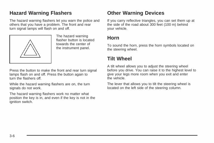
Hazard Warning FlashersThe hazard warning flashers let you warn the police andothers that you have a problem. The front and rearturn signal lamps will flash on and off.
The hazard warningflasher button is locatedtowards the center ofthe instrument panel.
Press the button to make the front and rear turn signallamps flash on and off. Press the button again toturn the flashers off.
While the hazard warning flashers are on, the turnsignals do not work.
The hazard warning flashers work no matter whatposition the key is in, and even if the key is not in theignition switch.
Other Warning DevicesIf you carry reflective triangles, you can set them up atthe side of the road about 300 feet (100 m) behindyour vehicle.
HornTo sound the horn, press the horn symbols located onthe steering wheel.
Tilt WheelA tilt wheel allows you to adjust the steering wheelbefore you drive. You can raise it to the highest level togive your legs more room when you exit and enterthe vehicle.
The lever that allows you to tilt the steering wheel islocated on the left side of the steering column.
3-6

To tilt the wheel, pull the lever down. Then, move thewheel to a comfortable position and raise the leverto lock the wheel in place.
Turn Signal/Multifunction Lever
The lever on the left side of the steering columnincludes the following:
• G Turn and Lane-Change Signals. See Turn andLane-Change Signals on page 3-8.
• 53 Headlamp High/Low-Beam Changer. SeeHeadlamp High/Low-Beam Changer on page 3-8.
• Flash-to-Pass. See Flash-to-Pass on page 3-8.
• O Exterior Lamp Control. See Headlampson page 3-15.
3-7

Turn and Lane-Change SignalsThe turn signal has two upward (for right) and twodownward (for left) positions. These positions allow youto signal a turn or a lane change.
To signal a turn, move the lever all the way up or down.When the turn is finished, the lever will returnautomatically.
An arrow on the instrumentpanel cluster will flash inthe direction of theturn or lane change.
To signal a lane change, raise or lower the lever untilthe arrow starts to flash. Hold it there until you completeyour lane change. The lever will return by itself whenyou release it.
As you signal a turn or a lane change, if the arrowsflash rapidly, a signal bulb may be burned out and otherdrivers will not see your turn signal. If a bulb is burnedout, replace it to help avoid an accident.
If the arrows do not go on at all when you signal a turn,check the fuse. See Fuses and Circuit Breakers onpage 5-119.
Headlamp High/Low-Beam ChangerTo change the headlamps from low beam to highbeam, push the turn signal lever away from you.
When the high beams areon, this light on theinstrument panel clusterwill also be on.
To change the headlamps from high beam to low beam,pull the turn signal lever toward you.
Flash-to-PassThis feature lets you use your high-beam headlamps tosignal a driver in front of you that you want to pass.
To use it, pull the turn signal/multifunction lever towardyou until the high-beam headlamps come on, thenrelease the lever to turn them off.
3-8

Windshield WipersBe sure to clear ice and snow from the wiper bladesbefore using them. If the wiper blades are frozen to thewindshield, gently loosen or thaw them. If the bladesdo become damaged, install new blades or bladeinserts. See Windshield Wiper Blade Replacement onpage 5-50.
Heavy snow or ice can overload the wiper motor. Acircuit breaker will stop the motor until it cools down.Clear away snow or ice to prevent an overload. Ifthe wipers gets stuck, turn the wipers off, clear awaythe snow or ice, and then turn the wipers back on. Use this lever, located on the right side of the steering
wheel, to operate the windshield wipers.
1 (High Speed): Move the lever to this position forsteady wiping at high speed.
6 (Low Speed): Move the lever to this position forsteady wiping at low speed.
& (Delay): Move the lever to this position to set adelay between wipes.
3-9
6 (Delay/Intermittent Speed Sensitive): When thelever is in the delay position, move the intermittent adjustband to set for shorter or longer delay cycles. To theleft of the adjust band are bars that indicate thefrequency of the wipes. Smaller bars mean the wipermovement is less frequent. Larger bars mean the wipermovement is more frequent.
During intermittent wiping mode, the delay cycle time issensitive to vehicle speed. As the vehicle speedincreases your delay cycle time will decrease and wipermovement will occur more frequently.
9 (Off): Move the lever to this position to turn off thewindshield wipers.
8 (Mist): Move the lever all the way down to mistand release for a single wiping cycle. The windshieldwipers will stop after one wipe and the lever will return toits original position. If additional wipes are needed,hold the band on mist longer.
As an added safety feature, if the wipers are on formore than 15 seconds, the vehicle’s headlamps will turnon automatically. They will turn off 15 seconds afterthe wipers are turned off.
Windshield WasherTo wash your windshield, press the button at the end ofthe lever until the washers begin.
{CAUTION:
In freezing weather, do not use your washeruntil the windshield is warmed. Otherwise thewasher fluid can form ice on the windshield,blocking your vision.
When you release the button, the washers will stop, butthe wipers will continue to wipe for about three timesor will resume the speed you were using before.
3-10

Rear Window Wiper/Washer
The rear windowwasher/wiper button islocated on the instrumentpanel below the climatecontrols.
{CAUTION:
In freezing weather, do not use your washeruntil the windshield is warmed. Otherwise thewasher fluid can form ice on the windshield,blocking your vision.
5 (Delay): Press this side of the button to turn on theintermittent wiping setting that has a longer delay.
Y (Washer Fluid): Press this button to wash and wipethe window.
The rear window washer uses the same fluid bottle asthe windshield washer. However, the rear windowwasher will run out of fluid before the windshield washer.If you can wash your windshield but not your rearwindows, check the fluid level.
Z (Rear Wiper): Press this side of the button to turnon an intermittent setting that has a shorter delay.
To turn either of the intermittent wiper settings off, pressthe opposite side of the button to turn it to the offposition. Pressing the button all the way down on eitherside will activate an intermittent wiper setting.
3-11

Cruise ControlWith cruise control, a speed of about 25 mph (40 km/h)or more can be maintained without keeping your footon the accelerator. This can really help on longtrips. Cruise control does not work at speeds below25 mph (40 km/h).
{CAUTION:
Cruise control can be dangerous where youcannot drive safely at a steady speed. So, donot use your cruise control on winding roadsor in heavy traffic.
Cruise control can be dangerous on slipperyroads. On such roads, fast changes in tiretraction can cause excessive wheel slip, andyou could lose control. Do not use cruisecontrol on slippery roads.
Setting Cruise Control
{CAUTION:
If you leave your cruise control on when youare not using cruise, you might hit a buttonand go into cruise when you do not want to.You could be startled and even lose control.Keep the cruise control switch off until youwant to use cruise control.
The cruise control buttonsare located on theoutboard side of thesteering wheel.
3-12

J (On/Off): Press this button to turn the cruise controlsystem on and off. The indicator light on the buttonwill be on when the cruise control is on and go off whenthe cruise control is turned off.
RES+ (Resume): Press this button to resume a setspeed and to accelerate the speed.
SET− (Set): Press this button to set a speed and todecrease the speed.
To set a speed do the following:
1. Press the on/off button to turn cruise control on.The indicator light on the button will come on.
2. Get to the speed you want.
3. Press the SET− control button and release it. TheCRUISE ENGAGED message will appear on theDriver Information Center (DIC) to show the systemis engaged.
4. Take your foot off the accelerator pedal.
When you apply the brakes or operate the clutch pedal,the cruise control will shut off.
If the vehicle is in cruise control and the TractionControl System (TCS) begins to limit wheel spin, thecruise control will automatically disengage. See TractionControl System (TCS) on page 4-6 and EnhancedTraction System (ETS) on page 4-9. When roadconditions allow, the cruise control can be used again.
Resuming a Set SpeedSuppose the cruise control is set at a desired speedand then the brake is applied. This will disengagethe cruise control. To return to the previously set speed,you do not need to go through the set process again.Once the vehicle is going about 25 mph (40 km/h)or more, you can press the RES+ part of the buttonbriefly.
The vehicle goes back to the previously set speed.
Increasing Speed While Using CruiseControlThere are two ways to go to a higher speed.
1. Disengage the cruise control by applying the brakepedal, but do not turn it off. Accelerate to a higherspeed and reset the cruise control.
2. If the cruise control system is already engaged,press the RES+ button. Hold it there until reachthe desired speed, and then release the button. Toincrease the vehicle speed in very small amounts,press the RES+ button briefly and then releaseit. Each time this is done, the vehicle goes about1 mph (1.6 km/h) faster.
3-13

Reducing Speed While Using CruiseControlIf the cruise control system is already engaged,
• Push and hold the SET− button until the lowerspeed desired is reached, then release it.
• To slow down in very small amounts, push theSET− button briefly. Each time this is done,the vehicle goes about 1 mph (1.6 km/h) slower.
Passing Another Vehicle While UsingCruise ControlUse the accelerator pedal to increase the vehicle speed.When you take your foot off the pedal, the vehicleslows down to the cruise control speed you set earlier.
Using Cruise Control on HillsHow well your cruise control will work on hills dependsupon the vehicle speed, load and the steepness ofthe hills. When going up steep hills, you might have tostep on the accelerator pedal to maintain the vehiclespeed. When going downhill, you might have to brake orshift to a lower gear to keep the vehicle speed down.When the brakes are applied the cruise control turns off.Many drivers find this to be too much trouble and donot use cruise control on steep hills.
Ending Cruise ControlTo end cruise control, step lightly on the brake pedal orthe clutch pedal if your vehicle has a manualtransmission.
Stepping on the brake pedal or clutch pedal will only endthe current cruise control session. Press the cruisecontrol on/off button to turn the system completely off.
Erasing Speed MemoryThe cruise control set speed memory is erased whenthe cruise control or the ignition is turned off.
3-14

Headlamps
The lever on the left side of the steering columnoperates the exterior lamps.
The exterior lamp switch has the following four positions:
2 (Headlamps): This position turns on theheadlamps, parking lamps, and taillamps.
; (Parking Lamps): This position turns on theparking lamps and taillamps only.
AUTO (Automatic Headlamp System): This positionautomatically turns on the Daytime Running Lampsduring daytime, and the headlamps, parking lamps, andtaillamps at night.
P (Off/On): This position is the momentary Off/Onswitch for the Automatic Headlamp System. In Canada,this only works when the vehicles with an automatictransaxle are in PARK (P) and vehicles with a manualtransaxle have the parking brake set and the vehicleis not moving.
When operating in AUTO, a momentary turn of theswitch to off/on will turn off the Automatic HeadlampSystem. An AUTO LIGHTS OFF message will display onthe driver information center and a chime will sound.Rotating the switch to off/on again will turn the AutomaticHeadlamp System back on. An AUTO LIGHTS ONmessage will display on the driver information center.The Automatic Headlamp System is always turned on atthe beginning of an ignition cycle for vehicles withmanual transaxle.
3-15

Wiper Activated HeadlampsThis feature activates the headlamps and parking lampsafter the windshield wipers are turned on. For thisfeature to work, automatic lighting must be enabled. SeeHeadlamps on page 3-15 for additional information.
When the ignition is turned off, the wiper-activatedheadlamps will immediately turn off. They will also turnoff 15 seconds after the windshield wiper control isturned off.
Headlamps on ReminderIf the driver’s door is opened with the ignition off andthe lamps on, a warning chime will sound. This lets youknow that the headlamps are still on.
Daytime Running Lamps (DRL)Daytime Running Lamps (DRL) can make it easier forothers to see the front of your vehicle during theday. DRL can be helpful in many different drivingconditions, but they can be especially helpful in the shortperiods after dawn and before sunset. Fully functionaldaytime running lamps are required on all vehiclesfirst sold in Canada.
Your vehicle has a light sensor on top of the instrumentpanel. Make sure it is not covered or the headlampswill come on when you do not need them.
The DRL system will make the headlamps come on atreduced brightness when the following conditionsare met:
• The ignition is on.
• The exterior lamp control is turned to AUTO.
• The light sensor detects daytime light.
• The shift lever is not in PARK (P).
While the DRL system is on, the taillamps, sidemarkerlamps, and instrument panel lights will not beilluminated.
The DRL system will be off any time your vehicle is inPARK (P). The DRL system on U.S. vehicles canalso be turned off by using the off/on switch for oneignition cycle.
As with any vehicle, you should turn on the regularheadlamp system when you need it.
3-16

Automatic Headlamp SystemWhen it is dark enough outside, your automatic systemwill turn on your headlamps at the normal brightnessalong with other lamps such as the taillamps,sidemarker, parking lamps, instrument panel lights, andinterior switch backlighting.
Your vehicle has a light sensor on top of the instrumentpanel. Make sure it is not covered, or the headlampsmay remain on when you do not need them.
The system may also be on when driving through aparking garage, heavy overcast weather or a tunnel.This is normal.
There is a delay in the transition between the daytimeand nighttime operation of the automatic lamp controlsystem so that driving under bridges or bright overheadstreet lights does not affect the system. The automaticlamp control system will only be affected when the lightsensor sees a change in lighting lasting longer thanthis delay.
If you start your vehicle in a dark garage, the automaticlamp system will come on immediately. Once youleave the garage, it will take about 20 seconds for theautomatic lamp system to change to DRL if it islight outside. During that delay, the instrument panelcluster may not be as bright as usual. Make surethe instrument panel brightness control is in the fullbright position. See Instrument Panel Brightnesson page 3-18.
To idle your vehicle with the system off, turn the ignitionon and turn the exterior light switch to the off/onposition. For Canadian vehicles, the transaxle must stayin PARK (P) for this function or the parking brakemust be set for vehicles with manual transaxles.
As with any vehicle, you should turn on the regularheadlamps when you need them.
3-17

Fog Lamps
If your vehicle is equippedwith a fog lamp button, it islocated to the right ofthe steering wheeland above the radio.
The ignition must be on to turn your fog lamps on.
Push the button to turn the fog lamps on. An indicatorlight on the cluster will come on when the fog lamps areon. Push the button again to turn the fog lamps off.
The parking lamps will automatically turn on andoff when the fog lamps are turned on and off.
The fog lamps will turn off while the high-beamheadlamps are turned on.
Some localities have laws that require the headlamps tobe on along with the fog lamps.
Instrument Panel Brightness
The control for this featureis located to the right ofthe steering wheeland above the radio.
Move the thumbwheel to the left to dim the lights or tothe right to brighten the lights.
The dome lamps will turn on when the thumbwheel ismoved completely to the right.
3-18

Dome Lamp
9 (Off): Move the lever to this position to turn the lampoff, even when a door is opened.
1 (Door): Move the lever to this position to turn thelamp on whenever a door is opened.
The dome lamp and mirror reading lamps will turn on ifthe lever is in the door position and the instrument panelbrightness control is turned to the brightest setting. SeeInstrument Panel Brightness on page 3-18.
+ (On): Move the lever to this position to turn on thedome lamp.
Entry/Exit LightingThe lamps inside your vehicle will go on when you openany door. These lamps will fade out after about20 seconds after all of the doors have been closed orwhen the ignition is turned to ON. These lamps will alsogo on when you press the unlock symbol button orthe horn symbol on the keyless entry system transmitter.
The lamps inside your vehicle will stay on for about20 seconds after your key is removed from the ignitionto provide an illuminated exit.
Mirror Reading LampsYour vehicle may have reading lamps on the rearviewmirror. Push the button to turn the reading lamps on andoff. The reading lamps will automatically come onwhen a door is open.
Rear Reading LampsPush the lens to turn the reading lamps on and off.
3-19

Electric Power ManagementThe vehicle has Electric Power Management (EPM) thatestimates the battery’s temperature and state ofcharge. It then adjusts the voltage for best performanceand extended life of the battery.
When the battery’s state of charge is low, the voltage israised slightly to quickly put the charge back in. Whenthe state of charge is high, the voltage is lowered slightlyto prevent overcharging. If the vehicle has a voltmetergage or voltage display on the Driver Information Center(DIC), you may see the voltage move up or down.This is normal. If there is a problem, an alert will bedisplayed.
The battery can be discharged at idle if the electricalloads are very high. This is true for all vehicles. This isbecause the generator (alternator) may not bespinning fast enough at idle to produce all the powerthat is needed for very high electrical loads.
A high electrical load occurs when several of thefollowing loads are on: headlamps, high beams, foglamps, rear window defogger, climate control fan at highspeed, heated seats, engine cooling fans, trailerloads, and loads plugged into accessory power outlets.
EPM works to prevent excessive discharge of thebattery. It does this by balancing the generator’s outputand the vehicle’s electrical needs. It can increaseengine idle speed to generate more power, wheneverneeded.
Battery Run-Down ProtectionYour vehicle has a battery saver feature designed toprotect the vehicle’s battery.
When any interior lamp is left on and the ignition isturned off, the battery rundown protection systemautomatically turns the lamp off after 20 minutes. Thisprevents draining of the battery.
Accessory Power Outlet(s)Accessory power outlets can be used to connectelectrical equipment such as a cellular phone or CBradio.
The accessory power outlets are located on theinstrument panel below the climate controls and at therear of the center console. There may be an outlet in therear cargo area on the passenger side.
To use the outlet, remove the cover. While not in use,always cover the outlet with the protective cap.
3-20

Notice: Leaving electrical equipment plugged in foran extended period of time while the vehicle is offwill drain the battery. Power is always suppliedto the outlets. Always unplug electrical equipmentwhen not in use and do not plug in equipmentthat exceeds the maximum 20 ampere rating.
Certain electrical accessories may not be compatiblewith the accessory power outlet and could resultin blown vehicle or adapter fuses. If you experience aproblem, see your dealer/retailer for additionalinformation on the accessory power outlet.
Notice: Adding any electrical equipment to yourvehicle may damage it or keep other componentsfrom working as they should. The repairs would notbe covered by your warranty. Do not use equipmentexceeding maximum amperage rating of 20 amperes.Check with your dealer/retailer before addingelectrical equipment.
When adding electrical equipment, be sure to follow theinstallation instructions included with the equipment.
Notice: Improper use of the power outlet can causedamage not covered by your warranty. Do nothang any type of accessory or accessory bracketfrom the plug because the power outlets aredesigned for accessory power plugs only.
Rear Power Plug for Converters
Your vehicle may have a power plug connector locatedin the rear cargo area on the passenger side behindthe service panel. The power connector wiring canbe accessed by removing the service panel to begininstallation.
3-21

This plug can be used to supply power to commercialconverters and contains four different circuits. Thefunctions of these circuits are as follows; a 40 Ampbattery service, a 10 Amp Accessory or Run service, a15 Amp Delayed Accessory service and a Groundcircuit.
Notice: Adding any electrical equipment to yourvehicle may damage it or keep other componentsfrom working as they should. The repairs would notbe covered by your warranty. Do not use equipmentexceeding maximum amperage rating of 40 amperes.Check with your dealer/retailer before addingelectrical equipment.
When adding electrical equipment, be sure to follow theinstallation instructions included with the equipment.
Notice: Improper use of the power outlet can causedamage not covered by your warranty. Do nothang any type of accessory or accessory bracketfrom the plug because the power outlets aredesigned for accessory power plugs only.
Notice: Leaving electrical equipment plugged in foran extended period of time while the vehicle is offwill drain the battery. Power is always suppliedto the outlets. Always unplug electrical equipmentwhen not in use and do not plug in equipmentthat exceeds the maximum 40 ampere rating.
Ashtray(s) and Cigarette LighterYour vehicle may have an ashtray and cigarette lighter.To use the lighter, located on the instrument panelbelow the climate controls, push it in all the way and letgo. When it is ready, it will pop back out by itself.
Notice: Holding a cigarette lighter in while it isheating will not allow the lighter to back away fromthe heating element when it is hot. Damage fromoverheating may occur to the lighter or heatingelement, or a fuse could be blown. Do not hold acigarette lighter in while it is heating. Do notuse equipment exceeding maximum amperage ratingof 15 amperes.
To clean the center console ashtray, remove the entireashtray and empty it.
Notice: If you put papers, pins, or other flammableitems in the ashtray, hot cigarettes or othersmoking materials could ignite them and possiblydamage your vehicle. Never put flammable items inthe ashtray.
3-22

Climate Controls
Climate Control SystemThe heating, cooling, and ventilation for your vehiclecan be controlled with this system.
For vehicles with remote start, the climate controlsystem comes on and uses the prior temperaturesettings selected before you exited the vehicle.
OperationTo change the current mode, select one of the following:
H (Vent): This mode directs air to the instrumentpanel outlets.
) (Bi-Level): This mode splits the air between theinstrument panel outlets and the floor outlets.
6 (Floor): This mode directs most of the air to thefloor outlets with some air directed to the windshield andside windows.
The right knob can also be used to select defog ordefrost mode. Information on defogging and defrostingcan be found later in this section.
Recirculation mode is not allowed in this mode.
9 (Fan): Turn the center knob clockwise orcounterclockwise to increase or decrease the fan speed.In any setting other than off, the fan will run continuouslywith the ignition on. The fan must be turned on to runthe air conditioning (AC) compressor.
9 (Off): To turn the fan off, turn the knob all the waycounterclockwise to the off position.
Temperature Control: Turn the left knob clockwise orcounterclockwise to increase or decrease thetemperature inside your vehicle.
@ (Recirculation): Press this button to preventoutside air and odors from entering your vehicle or tohelp heat or cool the air inside your vehicle more quickly.An indicator light above the symbol comes on in thismode. The air conditioning compressor also comes on.
3-23

This mode is not available for floor, defog and defrostmodes. When the recirculation button is pressed, therecirculation indicator light will flash five times and outsideair will be delivered. Operation in this mode duringperiods of high humidity and cool outside temperaturesmay result in increased window fogging. If windowfogging is experienced, select the defrost mode.
; (Outside Air): Press this button to allow outsideair to circulate through your vehicle. An indicatorlight above the symbol comes on in this mode.
# (Air Conditioning): Press this button to turn theair conditioning system on or off. When this buttonis pressed, an indicator light below the symbol comeson to show that the air conditioning is activated.
On hot days, open the windows to let hot inside airescape; then close them. This helps to reduce the timeit takes for your vehicle to cool down. It also helpsthe system to operate more efficiently.
For quick cool down on hot days:
1. Select H .
2. Select @ .
3. Select # .
4. Select the coolest temperature.
5. Select the highest fan speed.
Using these settings together for long periods of timemay cause the air inside of the vehicle to becometoo dry. To prevent this from happening, after the air inthe vehicle has cooled, turn off the recirculation bypressing the outside air button.
The air conditioning system removes moisture from theair, so a small amount of water might drip underneaththe vehicle while idling or after turning off the engine.This is normal.
The air conditioning compressor cannot be turned onwhen the fan is off.
3-24
Defogging and DefrostingFog on the inside of windows is a result of high humidity(moisture) condensing on the cool window glass. Thiscan be minimized if the climate control system isused properly. There are two modes to clear fog or frostfrom your windshield and side windows. Use thedefog mode to clear the windows of fog or moisture andwarm the passengers. Use the defrost mode toremove fog or frost from the windshield more quickly.For best results, clear all snow and ice from thewindshield before defrosting.
Turn the right knob to select the defog or defrost mode.
- (Defog): This mode directs approximately half of theair to the windshield and the side window outlets and halfto the floor outlets. When this mode is selected thesystem runs the air conditioning compressor. To defogthe windows faster, turn the temperature control knobclockwise to the warmest setting.
Recirculation mode is not available in defog mode.
0 (Defrost): This mode directs most of the air to thewindshield, with some air directed to the side windowoutlets and the floor outlets. When this mode is selectedthe system runs the air conditioning compressor. Todefrost the windows faster, turn the temperature controlknob clockwise to the warmest setting.
Recirculation mode is not available in defog mode.
Rear Window DefoggerThe rear window defogger uses a warming grid toremove fog from the rear window.
The rear window defogger will only work when theignition is in ON/RUN.
< (Rear): Press the button to turn the rear windowdefogger on or off. Be sure to clear as much snow fromthe rear window as possible. An indicator light belowthe symbol comes on to show that the rear windowdefogger is activated.
The rear window defogger turns off approximately15 minutes after the button is pressed. If turned onagain, the defogger only runs for approximately sevenminutes before turning off. If turned on again, thedefogger will only run for approximately seven minutesbefore turning off.
If the vehicle speed is greater than 50 mph (80 km/h)and the rear defogger is active, it remains on as long asthe speed is greater than 50 mph (80 km/h). Thedefogger can also be turned off by pressing the buttonagain or by turning off the engine.
3-25

If your vehicle has the remote start feature, the reardefogger automatically turns on if it is cold outside.When the vehicle transitions out of the remote startmode, the rear defogger turns off. See Remote KeylessEntry (RKE) System Operation on page 2-5
Notice: Do not use anything sharp on the inside ofthe rear window. If you do, you could cut ordamage the warming grid, and the repairs would notbe covered by your warranty. Do not attach atemporary vehicle license, tape, a decal or anythingsimilar to the defogger grid.
Outlet AdjustmentTurn the outlets and move the outlet vanes to changethe direction of the airflow and to open and closethe outlets.
Operation Tips• Clear away any ice, snow or leaves from the air
inlets at the base of the windshield that mayblock the flow of air into your vehicle.
• Use of non-GM approved hood deflectors mayadversely affect the performance of the system.
• Keep the path under the front seats clear of objectsto help circulate the air inside of your vehicle moreeffectively.
Passenger Compartment Air FilterPassenger compartment air, both outside air andrecirculated air, is routed through a passengercompartment filter. The filter removes certain particlesfrom the air, including pollen and dust particles.Reductions in airflow, which may occur more quickly industy areas, indicate that the filter needs to bereplaced early.
The filter should be replaced as part of routinescheduled maintenance. See Scheduled Maintenanceon page 6-4 for replacement intervals. See yourdealer for details on changing the filter. To find out whattype of filter to use, see Maintenance ReplacementParts on page 6-14.
3-26
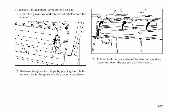
To access the passenger compartment air filter:
1. Open the glove box and remove all articles from theinside.
2. Release the glove box stops by pushing them bothoutward to let the glove box drop open completely.
3. Pull each of the three tabs of the filter access doordown and open the access door downward.
3-27
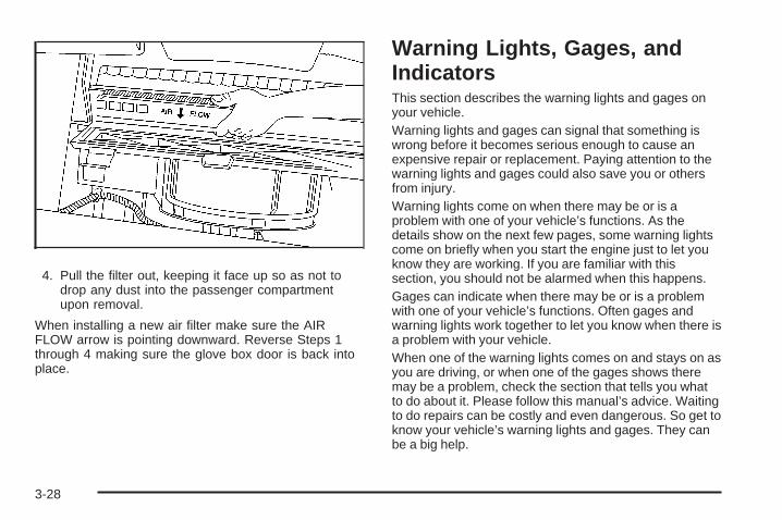
4. Pull the filter out, keeping it face up so as not todrop any dust into the passenger compartmentupon removal.
When installing a new air filter make sure the AIRFLOW arrow is pointing downward. Reverse Steps 1through 4 making sure the glove box door is back intoplace.
Warning Lights, Gages, andIndicatorsThis section describes the warning lights and gages onyour vehicle.Warning lights and gages can signal that something iswrong before it becomes serious enough to cause anexpensive repair or replacement. Paying attention to thewarning lights and gages could also save you or othersfrom injury.Warning lights come on when there may be or is aproblem with one of your vehicle’s functions. As thedetails show on the next few pages, some warning lightscome on briefly when you start the engine just to let youknow they are working. If you are familiar with thissection, you should not be alarmed when this happens.Gages can indicate when there may be or is a problemwith one of your vehicle’s functions. Often gages andwarning lights work together to let you know when there isa problem with your vehicle.When one of the warning lights comes on and stays on asyou are driving, or when one of the gages shows theremay be a problem, check the section that tells you whatto do about it. Please follow this manual’s advice. Waitingto do repairs can be costly and even dangerous. So get toknow your vehicle’s warning lights and gages. They canbe a big help.
3-28

Instrument Panel ClusterYour instrument panel cluster is designed to let you know at a glance how your vehicle is running. You will know howfast you are going, about how much fuel is left in the tank, and many other things you will need to drive safely andeconomically.
United States Cluster shown, SS and Canada similar
3-29

Speedometer and OdometerYour speedometer lets you see your speed in both milesper hour (mph) and kilometers per hour (km/h).Your vehicle’s odometer works together with the driverinformation center. You can set a Trip A and Trip Bodometer. See “Trip Information” under DIC Operationand Displays on page 3-46.The odometer mileage can be checked without thevehicle running. Simply open the driver’s door and themileage will be displayed briefly.If your vehicle ever needs a new odometer installed, thenew one will be set to the correct mileage total of the oldodometer.
Tachometer
The tachometerdisplays the enginespeed in revolutions perminute (rpm).
Notice: If you operate the engine with thetachometer in the red warning area, your vehiclecould be damaged and the damages would not becovered by your warranty. Do not operate theengine with the tachometer in the red warning area.
Safety Belt Reminders
Safety Belt Reminder LightWhen the engine is started, a chime will come on forseveral seconds to remind people to fasten their safetybelts, unless the driver’s safety belt is already buckled.
The safety belt light willalso come on and stay onfor several seconds, then itwill flash for several more.
This chime and light is repeated if the driver remainsunbuckled and the vehicle is in motion. If the driver’s beltis already buckled, neither the chime nor the light willcome on.
3-30
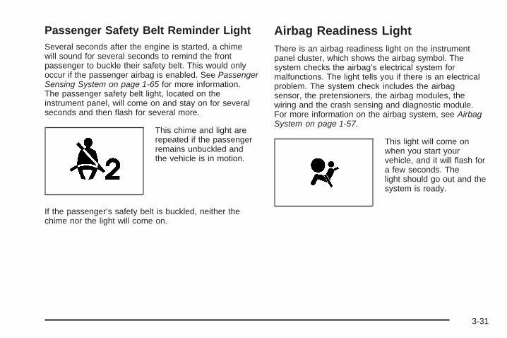
Passenger Safety Belt Reminder LightSeveral seconds after the engine is started, a chimewill sound for several seconds to remind the frontpassenger to buckle their safety belt. This would onlyoccur if the passenger airbag is enabled. See PassengerSensing System on page 1-65 for more information.The passenger safety belt light, located on theinstrument panel, will come on and stay on for severalseconds and then flash for several more.
This chime and light arerepeated if the passengerremains unbuckled andthe vehicle is in motion.
If the passenger’s safety belt is buckled, neither thechime nor the light will come on.
Airbag Readiness LightThere is an airbag readiness light on the instrumentpanel cluster, which shows the airbag symbol. Thesystem checks the airbag’s electrical system formalfunctions. The light tells you if there is an electricalproblem. The system check includes the airbagsensor, the pretensioners, the airbag modules, thewiring and the crash sensing and diagnostic module.For more information on the airbag system, see AirbagSystem on page 1-57.
This light will come onwhen you start yourvehicle, and it will flash fora few seconds. Thelight should go out and thesystem is ready.
3-31

If the airbag readiness light stays on after you start thevehicle or comes on when you are driving, yourairbag system may not work properly. Have your vehicleserviced right away.
{CAUTION:
If the airbag readiness light stays on after youstart your vehicle, it means the airbag systemmay not be working properly. The airbags inyour vehicle may not inflate in a crash, or theycould even inflate without a crash. To helpavoid injury to yourself or others, have yourvehicle serviced right away if the airbagreadiness light stays on after you start yourvehicle.
The airbag readiness light should flash for a fewseconds when you start the engine. If the light does notcome on then, have it fixed immediately. If there is aproblem with the airbag system, an airbag DriverInformation Center (DIC) message may also come on.See DIC Warnings and Messages on page 3-48 formore information.
Passenger Airbag Status IndicatorYour vehicle has the passenger sensing system.Your instrument panel has a passenger airbag statusindicator.
When you start the vehicle, the passenger airbag statusindicator will light ON and OFF, or the symbol for onand off, for several seconds as a system check. If youuse remote start to start your vehicle from a distance,if your vehicle has this feature, you may not seethe system check. Then, after several more seconds,the status indicator will light either ON or OFF, or eitherthe on or off symbol to let you know the status of theright front passenger’s frontal airbag.
United States Canada
3-32

If the word ON or the on symbol is lit on the passengerairbag status indicator, it means that the right frontpassenger’s frontal airbag is enabled (may inflate).
{CAUTION:
If the on indicator comes on when you have arear-facing child restraint installed in the rightfront passenger’s seat, it means that thepassenger sensing system has not turned offthe passenger’s frontal airbag. A child in arear-facing child restraint can be seriouslyinjured or killed if the right front passenger’sairbag inflates. This is because the back of therear-facing child restraint would be very closeto the inflating airbag. Do not use a rear-facingchild restraint in the right front passenger’sseat if the airbag is turned on.
{CAUTION:
Even though the passenger sensing system isdesigned to turn off the right front passenger’sfrontal airbag if the system detects a rear-facingchild restraint, no system is fail-safe, and noone can guarantee that an airbag will not deployunder some unusual circumstance, eventhough it is turned off. We recommend thatrear-facing child restraints be secured in therear seat, even if the airbag is off.
If the word OFF or the off symbol is lit on the airbagstatus indicator, it means that the passenger sensingsystem has turned off the right front passenger’s frontalairbag. See Passenger Sensing System on page 1-65for more on this, including important safety information.
3-33
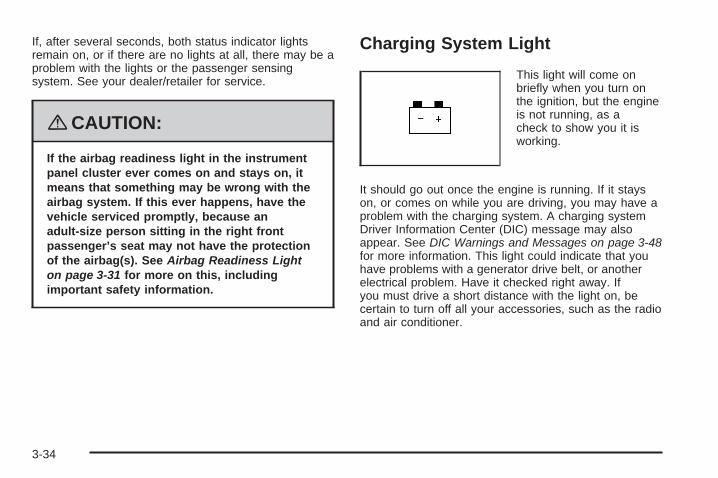
If, after several seconds, both status indicator lightsremain on, or if there are no lights at all, there may be aproblem with the lights or the passenger sensingsystem. See your dealer/retailer for service.
{CAUTION:
If the airbag readiness light in the instrumentpanel cluster ever comes on and stays on, itmeans that something may be wrong with theairbag system. If this ever happens, have thevehicle serviced promptly, because anadult-size person sitting in the right frontpassenger’s seat may not have the protectionof the airbag(s). See Airbag Readiness Lighton page 3-31 for more on this, includingimportant safety information.
Charging System Light
This light will come onbriefly when you turn onthe ignition, but the engineis not running, as acheck to show you it isworking.
It should go out once the engine is running. If it stayson, or comes on while you are driving, you may have aproblem with the charging system. A charging systemDriver Information Center (DIC) message may alsoappear. See DIC Warnings and Messages on page 3-48for more information. This light could indicate that youhave problems with a generator drive belt, or anotherelectrical problem. Have it checked right away. Ifyou must drive a short distance with the light on, becertain to turn off all your accessories, such as the radioand air conditioner.
3-34

Up-Shift Light
Your vehicle may have anup-shift light.
When this light comes on, you should shift to the nexthigher gear if weather, road, and traffic conditions allowyou to.
See Manual Transmission Operation on page 2-31 formore information.
Brake System Warning LightYour vehicle’s hydraulic brake system is divided into twoparts. If one part is not working, the other part canstill work and stop you. For good braking, though, youneed both parts working well.
If the warning light comes on, there is a brake problem.Have your brake system inspected right away.
This light should come on briefly when the engine isstarted. If it does not come on then, have it fixed so itwill be ready to warn you if there is a problem.
When the ignition is on, the brake system warning lightwill also come on when you set the parking brake.The light will stay on if your parking brake doesnot release fully. If it stays on after your parking brake isfully released, it means you have a brake problem.
United States Canada
3-35

If the light comes on while you are driving, pull off theroad and stop carefully. Make sure the parking brake isfully released. You may notice that the pedal is harderto push or, the pedal may go closer to the floor. Itmay take longer to stop. If the light is still on, have thevehicle towed for service. See Towing Your Vehicleon page 4-32.
{CAUTION:
Your brake system may not be workingproperly if the brake system warning light ison. Driving with the brake system warning lighton can lead to an accident. If the light is stillon after you have pulled off the road andstopped carefully, have the vehicle towed forservice.
Antilock Brake System WarningLight
For vehicles with theAntilock Brake System(ABS), this light will comeon briefly when youstart the engine.
That is normal. If the light does not come on then, have itfixed so it will be ready to warn you if there is a problem.If the ABS light stays on, turn the ignition off, if the lightcomes on when you are driving, stop as soon as it issafely possible and turn the ignition off. Then start theengine again to reset the system. If the ABS light stillstays on, or comes on again while you are driving, yourvehicle needs service. If the regular brake systemwarning light is not on, you still have brakes, but you donot have antilock brakes. If the regular brake systemwarning light is also on, you do not have antilock brakesand there is a problem with your regular brakes. SeeBrake System Warning Light on page 3-35
For vehicles with a Driver Information Center (DIC), seeDIC Warnings and Messages on page 3-48 for allbrake related DIC messages.
3-36

Enhanced Traction System WarningLight
For vehicles with theEnhanced Traction System(ETS), this warning lightshould come on briefly asyou start the engine.
If the warning light does not come on, have it fixed so itwill be ready to warn you if there is a problem.
If the warning light is on and not flashing, the ETSsystem may have been disabled. Check all relatedDriver Information Center (DIC) messages to determinewhether the system has been turned off or if thesystem is not working properly and your vehicle requiresservice. If the ETS has been disabled, wheel spin willnot be limited.
If the warning light is on and flashing, the ETS isactively working. The LOW TRACTION DIC messagewill also appear when the system is actively limitingwheel spin.
See Enhanced Traction System (ETS) on page 4-9 andDIC Warnings and Messages on page 3-48 for moreinformation.
Electronic Stability Control(ESC)/Traction Control System(TCS) Indicator/Warning Light
This light is located in thecenter of the instrumentpanel cluster.
For vehicles that have the Electronic Stability Control(ESC) system or the Traction Control System (TCS), thiswarning light should come on briefly when the engineis started.
If the warning light does not come on then, have it fixedso it will be ready to warn you if there is a problem.This light, along with the appropriate Driver InformationCenter (DIC) messages, indicates when the ESCsystem and the TCS are working or are disabled.
3-37

If this light is on and not flashing, the TCS andpotentially the ESC system have been disabled. Checkyour DIC messaging to determine which feature(s) isno longer functioning and whether it is because ofthe driver turning off the feature(s), or the system maynot be working properly and your vehicle requiresservice. If the TCS is disabled, wheel spin will not belimited. If the ESC system is disabled, the systemwill not aid in maintaining vehicle directional control. Ineither case, adjust your driving accordingly.
If the light is on and flashing, the TCS or the ESCsystem is actively working. Check the DIC messagingfor details to determine which system is working. Ifthe LOW TRACTION message appears, the system islimiting wheel spin. If the ESC ACTIVE messageappears, the system is aiding in maintaining vehicledirectional control.
See Electronic Stability Control (ESC) on page 4-10 andTraction Control System (TCS) on page 4-6 for moreinformation.
See DIC Warnings and Messages on page 3-48 formore information on the messages associated with thislight.
Engine Coolant TemperatureWarning Light
The engine coolanttemperature warning lightwill come on when theengine has overheated.
If this happens you should pull over and turn off theengine as soon as possible. See Engine Overheating onpage 5-26 for more information.
Notice: Driving with the engine coolant temperaturewarning light on could cause your vehicle tooverheat. See Engine Overheating on page 5-26.Your vehicle could be damaged, and it might not becovered by your warranty. Never drive with theengine coolant temperature warning light on.
This light will also come on briefly when starting yourvehicle. If it does not, have your vehicle serviced.
3-38

Engine Coolant Temperature Gage
Your vehicle has anengine coolant temperaturegage. With the ignitionturned to RUN, this gageshows the enginecoolant temperature.
If the gage pointer moves into the red area, your engineis too hot. It means that your engine coolant hasoverheated.
If you have been operating your vehicle under normaldriving conditions, you should pull off the road, stop yourvehicle and turn off the engine as soon as possible.
See Engine Overheating on page 5-26.
Tire Pressure Light
Your vehicle may have atire pressure light.
This light comes on briefly when the engine is startedand provides information about tire pressures andthe Tire Pressure Monitoring System.
When the Light is SolidThis indicates that one or more of your tires aresignificantly underinflated.
A tire pressure message in the Driver InformationCenter (DIC), may accompany the light. See DICWarnings and Messages on page 3-48 for moreinformation. Stop and check your tires as soon as it issafe to do so. If underinflated, inflate to the properpressure. See Tires on page 5-52 for more information.
3-39

When the Light Flashes First and Then isSolidThis indicates that there may be a problem with the TirePressure Monitor System. The light will flash forabout a minute and then stay on solid for the remainderof the ignition cycle. This sequence will repeat withevery ignition cycle. See Tire Pressure Monitor Systemon page 5-61 for more information.
Malfunction Indicator Lamp
Check Engine LightA computer system called OBD II (On-BoardDiagnostics-Second Generation) monitors operation ofthe fuel, ignition, and emission control systems. It makessure that emissions are at acceptable levels for thelife of the vehicle, helping to produce a cleanerenvironment.
The check engine lightcomes on to indicate thatthere is an OBD IIproblem and service isrequired.
Malfunctions often are indicated by the system beforeany problem is apparent. This can prevent more seriousdamage to your vehicle. This system is also designedto assist your service technician in correctly diagnosingany malfunction.
Notice: If you keep driving your vehicle with thislight on, after a while, the emission controlsmight not work as well, your vehicle’s fuel economymight not be as good, and the engine might notrun as smoothly. This could lead to costly repairsthat might not be covered by your warranty.
3-40
Notice: Modifications made to the engine,transmission, exhaust, intake, or fuel system ofyour vehicle or the replacement of the original tireswith other than those of the same Tire PerformanceCriteria (TPC) can affect your vehicle’s emissioncontrols and can cause this light to come on.Modifications to these systems could lead to costlyrepairs not covered by your warranty. This couldalso result in a failure to pass a required EmissionInspection/Maintenance test. See Accessoriesand Modifications on page 5-3.
This light comes on, as a check to show it is working,when the ignition is turned ON/RUN but the engine is notrunning. If the light does not come on, have it repaired.This light also comes on during a malfunction inone of two ways:
• Light Flashing — A misfire condition has beendetected. A misfire increases vehicle emissionsand could damage the emission control system onyour vehicle. Diagnosis and service might berequired.
• Light On Steady — An emission control systemmalfunction has been detected on your vehicle.Diagnosis and service might be required.
If the Light is FlashingThe following can prevent more serious damage to yourvehicle:
• Reduce vehicle speed.
• Avoid hard accelerations.
• Avoid steep uphill grades.
• If you are towing a trailer, reduce the amount ofcargo being hauled as soon as it is possible.
If the light stops flashing and remains on steady, see “Ifthe Light Is On Steady” following.
If the light continues to flash, when it is safe to do so,stop the vehicle. Find a safe place to park the vehicle.Turn the ignition off, wait at least 10 seconds, and restartthe engine. If the light remains on steady, see “If theLight Is On Steady” following. If the light is still flashing,follow the previous steps and see your dealer/retailerfor service as soon as possible.
3-41

If the Light Is On SteadyYou might be able to correct the emission systemmalfunction by considering the following:
Did you recently put fuel into your vehicle?
If so, reinstall the fuel cap, making sure to fully installthe cap. See Filling the Tank on page 5-7. Thediagnostic system can determine if the fuel cap hasbeen left off or improperly installed. A loose or missingfuel cap allows fuel to evaporate into the atmosphere.A few driving trips with the cap properly installed shouldturn the light off.
Did you just drive through a deep puddle of water?
If so, your vehicle’s electrical system might be wet. Thecondition is usually corrected when the electrical systemdries out. A few driving trips should turn the light off.
Have you recently changed brands of fuel?
If so, be sure to fuel your vehicle with quality fuel. SeeGasoline Octane on page 5-5. Poor fuel quality causesthe engine not to run as efficiently as designed. Youmight notice this as stalling after start-up, stalling whenyou put the vehicle into gear, misfiring, hesitation onacceleration, or stumbling on acceleration — theseconditions might go away once the engine is warmed up.This will be detected by the system and cause the light toturn on.
If you experience one or more of these conditions,change the fuel brand you use. It will require at leastone full tank of the proper fuel to turn the light off.
If none of the above steps have made the light turn off,your dealer/retailer can check the vehicle. Yourdealer/retailer has the proper test equipment anddiagnostic tools to fix any mechanical or electricalproblems that might have developed.
Emissions Inspection and MaintenanceProgramsSome state/provincial and local governments have ormight begin programs to inspect the emission controlequipment on your vehicle. Failure to pass thisinspection could prevent you from getting a vehicleregistration.
Here are some things you need to know to help yourvehicle pass an inspection:
Your vehicle will not pass this inspection if the checkengine light is on or not working properly.
3-42

Your vehicle will not pass this inspection if the OBD(on-board diagnostic) system determines that criticalemission control systems have not been completelydiagnosed by the system. The vehicle would beconsidered not ready for inspection. This can happen ifyou have recently replaced the battery or if thebattery has run down. The diagnostic system isdesigned to evaluate critical emission control systemsduring normal driving. This can take several daysof routine driving. If you have done this and your vehiclestill does not pass the inspection for lack of OBDsystem readiness, your dealer/retailer can prepare thevehicle for inspection.
Oil Pressure Light
{CAUTION:
Do not keep driving if the oil pressure is low. Ifyou do, your engine can become so hot that itcatches fire. You or others could be burned.Check your oil as soon as possible and haveyour vehicle serviced.
Notice: Lack of proper engine oil maintenance maydamage the engine. The repairs would not becovered by your warranty. Always follow themaintenance schedule in this manual for changingengine oil.
This light will come onbriefly when you start yourengine. If it does not,have your vehicle serviced.
When the light comes on and stays on, it means that oilis not flowing through your engine properly. Youcould be low on oil and you might have some othersystem problem.
3-43
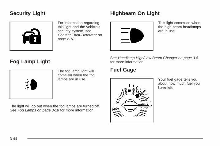
Security Light
For information regardingthis light and the vehicle’ssecurity system, seeContent Theft-Deterrent onpage 2-18.
Fog Lamp Light
The fog lamp light willcome on when the foglamps are in use.
The light will go out when the fog lamps are turned off.See Fog Lamps on page 3-18 for more information.
Highbeam On Light
This light comes on whenthe high-beam headlampsare in use.
See Headlamp High/Low-Beam Changer on page 3-8for more information.
Fuel Gage
Your fuel gage tells youabout how much fuel youhave left.
3-44
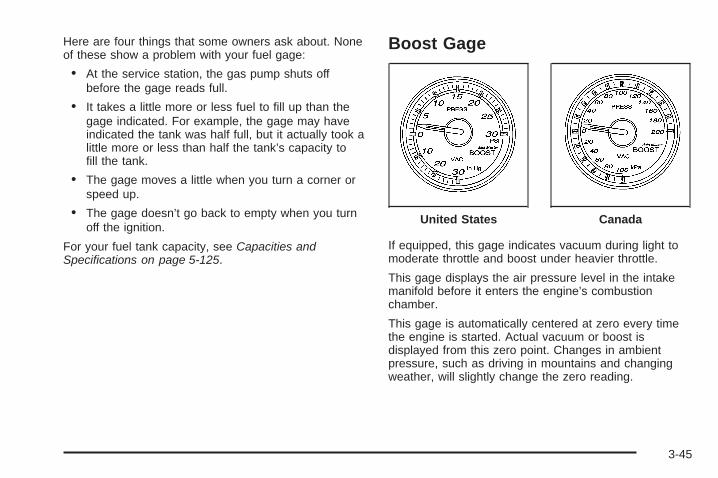
Here are four things that some owners ask about. Noneof these show a problem with your fuel gage:
• At the service station, the gas pump shuts offbefore the gage reads full.
• It takes a little more or less fuel to fill up than thegage indicated. For example, the gage may haveindicated the tank was half full, but it actually took alittle more or less than half the tank’s capacity tofill the tank.
• The gage moves a little when you turn a corner orspeed up.
• The gage doesn’t go back to empty when you turnoff the ignition.
For your fuel tank capacity, see Capacities andSpecifications on page 5-125.
Boost Gage
If equipped, this gage indicates vacuum during light tomoderate throttle and boost under heavier throttle.
This gage displays the air pressure level in the intakemanifold before it enters the engine’s combustionchamber.
This gage is automatically centered at zero every timethe engine is started. Actual vacuum or boost isdisplayed from this zero point. Changes in ambientpressure, such as driving in mountains and changingweather, will slightly change the zero reading.
United States Canada
3-45
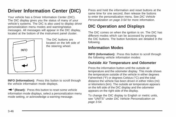
Driver Information Center (DIC)Your vehicle has a Driver Information Center (DIC).The DIC display gives you the status of many of yourvehicle’s systems. The DIC is also used to display driverpersonalization menu modes and warning/statusmessages. All messages will appear in the DIC display,located at the bottom of the instrument panel cluster.
The DIC buttons arelocated on the left side ofthe steering wheel.
INFO (Information): Press this button to scroll throughthe vehicle information mode displays.
r (Reset): Press this button to reset some vehicleinformation mode displays, select a personalization menumode setting, or acknowledge a warning message.
Press and hold the information and reset buttons at thesame time for one second, then release the buttonsto enter the personalization menu. See DIC VehiclePersonalization on page 3-54 for more information.
DIC Operation and DisplaysThe DIC comes on when the ignition is on. The DIC hasdifferent modes which can be accessed by pressingthe DIC buttons. The button functions are detailed in thefollowing.
Information Modes
INFO (Information): Press this button to scroll throughthe following vehicle information modes:
Outside Air Temperature and OdometerPress the information button until the outside airtemperature and the odometer display. This mode showsthe temperature outside of the vehicle in either degreesFahrenheit (°F) or degrees Celsius (°C) and the totaldistance the vehicle has been driven in either miles (mi)or kilometers (km). The outside air temperature appearson the left side of the DIC display and the odometerappears on the right side of the display.
To change the DIC display to English or metric units,see “UNITS” under DIC Vehicle Personalization onpage 3-54.
3-46

TRIP A or TRIP BPress the information button until TRIP A or TRIP Bdisplay. These modes show the current distancetraveled since the last reset for each trip odometer ineither miles (mi) or kilometers (km). Both odometers canbe used at the same time.
To reset the trip odometer to zero, press and hold thereset button for a few seconds while the desiredtrip odometer is displayed.
FUEL RANGEPress the information button until FUEL RANGEdisplays. This mode shows the remaining distance youcan drive without refueling in either miles (mi) orkilometers (km). It is based on fuel economy and thefuel remaining in the tank.
When the fuel level is low, FUEL RANGE LOW displays.
The fuel economy data used to determine fuel rangeis an average of recent driving conditions. As yourdriving conditions change, this data is gradually updated.The FUEL RANGE mode cannot be reset.
MPG (L/100 KM) AVG (Average)Press the information button until MPG (L/100 KM) AVGdisplays. This mode shows how many miles pergallon (mpg) or liters per 100 kilometers (L/100 km) yourvehicle is getting based on current and past drivingconditions.
To reset the average fuel economy, press and hold thereset button while MPG (L/100 KM) AVG is displayed.Average fuel economy is then calculated startingfrom that point. If the average fuel economy is not reset,it is continually updated each time you drive.
MPG (L/100 KM) INST (Instantaneous)Press the information button until MPG (L/100 KM) INSTdisplays. This mode shows the current fuel economyat a particular moment and changes frequently asdriving conditions change. This mode shows theinstantaneous fuel economy in miles per gallon (mpg) orliters per 100 kilometers (L/100 km). Unlike averagefuel economy, this screen cannot be reset.
AV (Average) SPEEDPress the information button until AV SPEED displays.This mode shows the vehicle’s average speed inmiles per hour (mph) or kilometers per hour (km/h).
To reset the average vehicle speed, press and hold thereset button while AV SPEED is displayed.
3-47

OIL LIFEPress the information button until OIL LIFE displays.The engine oil life system shows an estimate of the oil’sremaining useful life. It shows 100% when the systemis reset after an oil change. It alerts you to change the oilon a schedule consistent with your driving conditions.
In addition to the engine oil life system monitoring the oillife, additional maintenance is recommended in theMaintenance Schedule in this manual. See Engine Oilon page 5-15 and Scheduled Maintenance on page 6-4.
Always reset the engine oil life system after an oilchange. See “How to Reset the Engine Oil Life System”under Engine Oil Life System on page 5-19.
COOLANTPress the information button until COOLANT displays.This mode shows the temperature of the engine coolantin either degrees Fahrenheit (°F) or degrees Celsius (°C).
Tire PressureIf your vehicle has a Tire Pressure Monitor System(TPMS), the pressure for each tire can be viewed in theDIC. The tire pressure is shown in either pounds persquare inch (psi) or kilopascals (kPa). Press theinformation button until LF ## PSI (kPa) ## RF displaysfor the front tires. Press the information button againuntil LR ## PSI (kPa) ## RR displays for the rear tires.
If a low tire pressure condition is detected by the systemwhile driving, a message advising you to check the tirepressure appears in the display. See Inflation - TirePressure on page 5-60 and DIC Warnings and Messageson page 3-48 for more information.
DIC Warnings and MessagesThese messages appear if there is a problem detectedin one of your vehicle’s systems.
A message clears when the vehicle’s condition is nolonger present. To acknowledge a message and clear itfrom the display, press and hold any of the DICbuttons. If the condition is still present, the warningmessage comes back on the next time the vehicle isturned off and back on. With most messages, a warningchime sounds when the message displays. Yourvehicle may have other warning messages.
AUTO (Automatic) LIGHTS OFFThis message displays if the automatic headlampsystem is disabled with the headlamp switch. SeeAutomatic Headlamp System on page 3-17 for moreinformation.
3-48

AUTO (Automatic) LIGHTS ONThis message displays if the automatic headlampsystem is enabled with the headlamp switch. SeeAutomatic Headlamp System on page 3-17 for moreinformation.
BRAKE FLUIDThis message displays, while the ignition is on, whenthe brake fluid level is low. The brake system warninglight on the instrument panel cluster also comes on. SeeBrake System Warning Light on page 3-35 for moreinformation. Have the brake system serviced byyour dealer/retailer as soon as possible.
CHANGE OIL SOONThis message displays when the life of the engine oilhas expired and it should be changed.
When this message is acknowledged and cleared fromthe display, the engine oil life system must still bereset separately. See Engine Oil Life System onpage 5-19 and Scheduled Maintenance on page 6-4 formore information.
CHECK GAS CAPThis message displays if the fuel cap has not been fullytightened. Recheck the fuel cap to make sure that itis on properly. A few driving trips with the cap properlyinstalled should turn the message off.
CHECK TIRE PRESS (Pressure)If your vehicle has a Tire Pressure Monitor System(TPMS), this message displays when the pressure in oneor more of the vehicle’s tires needs to be checked. If a tirepressure message appears on the DIC, stop as soon asyou can. Have the tire pressures checked and set tothose shown on the Tire Loading Information label. SeeTires on page 5-52, Loading Your Vehicle on page 4-27,and Inflation - Tire Pressure on page 5-60. The DIC alsoshows the tire pressure values. See DIC Operation andDisplays on page 3-46. If the tire pressure is low, the lowtire pressure warning light comes on. See Tire PressureLight on page 3-39.
COMPETITIVE MODEIf your vehicle has this feature, this message displayswhen the Competitive Driving mode is selected.The Traction Control System (TCS) will not be operatingwhile in the Competitive Driving mode and theESC/TCS light on the instrument panel cluster will be onsolid. Adjust your driving accordingly. See TractionControl System (TCS) on page 4-6, Electronic StabilityControl (ESC) on page 4-10, and Electronic StabilityControl (ESC)/Traction Control System (TCS)Indicator/Warning Light on page 3-37 for moreinformation.
3-49

COOLING MODE ONThis message may display on some vehicles. Undersevere conditions, hot ambient temperatures, steepgrades, and towing, your vehicle may experience moretransmission shifting. This is temporary and normalunder these conditions. This does not require engine ortransmission service.
CRUISE ENGAGEDThis message displays when the cruise control systemis active. See Cruise Control on page 3-12 for moreinformation.
DOOR AJARThis message displays if one or more of the vehicle’sdoors are not closed properly. Make sure that thedoor(s) are closed completely.
ENGINE DISABLEDThis message displays if the starting of the engine isdisabled. Have your vehicle serviced by yourdealer/retailer immediately.
ENG (Engine) PWR (Power) REDUCEDThis message displays to inform you that the vehiclehas reduced engine power to avoid damaging theengine. Reduced engine power can affect the vehicle’sability to accelerate. If this message is on, but thereis no reduction in performance, proceed to yourdestination. The performance may be reduced the nexttime the vehicle is driven. The vehicle may be drivenat a reduced speed while this message is on, butacceleration and speed may be reduced. Anytime thismessage stays on, the vehicle should be taken toyour dealer/retailer for service as soon as possible.
ESC (Electronic Stability Control) ACTIVEIf your vehicle has Electronic Stability Control (ESC),this message displays and the ESC/TCS light onthe instrument panel cluster flashes when ESC isassisting you with directional control of the vehicle. Youmay feel or hear the system working and see thismessage displayed in the DIC. Slippery road conditionsmay exist when this message is displayed, so adjustyour driving accordingly. This message may stay on fora few seconds after ESC stops assisting you withdirectional control of the vehicle. This is normal whenthe system is operating. See Electronic Stability Control(ESC) on page 4-10 and Electronic Stability Control(ESC)/Traction Control System (TCS) Indicator/WarningLight on page 3-37 for more information.
3-50

ESC (Electronic Stability Control) NOTREADYIf your vehicle has Electronic Stability Control (ESC),this message may display briefly after starting thevehicle if the system’s sensors are not yet calibrated.The system is not functional until the messagestops displaying. Adjust your driving accordingly. Whenthe message is no longer displayed, the system isfunctional. See Electronic Stability Control (ESC) onpage 4-10 for more information.
ESC (Electronic Stability Control) OFFIf your vehicle has Electronic Stability Control (ESC),this message displays and the ESC/TCS light onthe instrument panel cluster comes on solid when ESCis turned off. Adjust your driving accordingly. SeeElectronic Stability Control (ESC) on page 4-10 andElectronic Stability Control (ESC)/Traction ControlSystem (TCS) Indicator/Warning Light on page 3-37 formore information.
GATE AJARThis message displays when the liftgate is not closedcompletely. Make sure that the liftgate is closedcompletely. See Liftgate on page 2-12 for moreinformation.
ICE POSSIBLEThis message displays when the outside air temperatureis cold enough to create icy road conditions. Adjustyour driving accordingly.
KEY FOB BATT (Battery) LOWThis message displays if the Remote Keyless Entry(RKE) transmitter battery is low. Replace the battery inthe transmitter. See “Battery Replacement” underRemote Keyless Entry (RKE) System Operation onpage 2-5.
LAUNCH CONTROLIf your vehicle has this feature, this message displaysafter the COMPETITIVE MODE message when thevehicle is stopped. Launch control is a form of tractioncontrol to control wheel spin while launching thevehicle during closed track events and competitivedriving venues. The system will exit to COMPETITIVEMODE after the vehicle is launched. See“COMPETITIVE MODE” earlier in this section. See“Launch Control” under Electronic Stability Control(ESC) on page 4-10 for more information.
LOW FUELThis message displays when your vehicle is low on fuel.Refill the fuel tank as soon as possible. See FuelGage on page 3-44, Fuel on page 5-5, and Filling theTank on page 5-7 for more information.
3-51
LOW TRACTIONIf your vehicle has the Enhanced Traction System (ETS)or Traction Control System (TCS), this messagedisplays and the ETS light or the ESC/TCS light on theinstrument panel cluster flashes when the system isactively limiting wheel spin. Slippery road conditions mayexist if this message is displayed, so adjust yourdriving accordingly. This message stays on for a fewseconds after the system stops limiting wheel spin. SeeEnhanced Traction System (ETS) on page 4-9 orTraction Control System (TCS) on page 4-6 andEnhanced Traction System Warning Light on page 3-37or Electronic Stability Control (ESC)/Traction ControlSystem (TCS) Indicator/Warning Light on page 3-37 formore information.
PARKING BRAKEThis message displays if the parking brake is leftengaged. See Parking Brake on page 2-33 for moreinformation.
POWER STEERINGThis message displays if a problem has been detectedwith the electric power steering. Have your vehicleserviced by your dealer/retailer immediately.
SERVICE AIR BAGThis message displays when there is a problem with theairbag system. Have your vehicle serviced by yourdealer/retailer immediately.
SERVICE ESC (ELECTRONIC STABILITYCONTROL)If your vehicle has Electronic Stability Control (ESC),this message displays and a chime sounds if there hasbeen a problem detected with ESC. The ESC/TCSlight also appears on the instrument panel cluster. Thislight stays on solid as long as the detected problemremains present. When this message displays, thesystem is not working. Adjust your driving accordingly.See Electronic Stability Control (ESC) on page 4-10 andElectronic Stability Control (ESC)/Traction ControlSystem (TCS) Indicator/Warning Light on page 3-37 formore information.
If this message turns on while you are driving, pull offthe road as soon as possible and stop carefully.Try resetting the system by turning the ignition off andthen back on. If this message still stays on or turns backon again while you are driving, your vehicle needsservice. Have the ESC inspected by your dealer/retaileras soon as possible.
3-52

SERVICE TRACTIONIf your vehicle has the Enhanced Traction System (ETS)or Traction Control System (TCS), this messagedisplays and a chime sounds when the system is notfunctioning properly. The ETS light or the ESC/TCS lightalso appears on the instrument panel cluster. Thislight stays on solid as long as the detected problemremains present. When this message displays, thesystem is not working. Adjust your driving accordingly.See Enhanced Traction System (ETS) on page 4-9or Traction Control System (TCS) on page 4-6and Enhanced Traction System Warning Light onpage 3-37 or Electronic Stability Control (ESC)/TractionControl System (TCS) Indicator/Warning Light onpage 3-37 for more information. Have the systemserviced by your dealer/retailer as soon as possible.
SVC (Service) BRAKE SYSTEMThis message may display if you have a turbochargedvehicle with Electronic Stability Control (ESC) and ifthe hydraulic brake boost is not working or is workingimproperly. Have the brake system serviced by yourdealer/retailer as soon as possible.
SVC (Service) TIRE MONITORIf your vehicle has a Tire Pressure Monitor System(TPMS), this message displays if a part on the TPMS isnot working properly. The tire pressure light alsoflashes and then remains on during the same ignitioncycle. See Tire Pressure Light on page 3-39. Severalconditions may cause this message to appear. See TirePressure Monitor Operation on page 5-63 for moreinformation. If the warning comes on and stays on, theremay be a problem with the TPMS. See yourdealer/retailer.
TRACTION OFFIf your vehicle has the Enhanced Traction System (ETS)or Traction Control System (TCS), this messagedisplays and the ETS light or the ESC/TCS light on theinstrument panel cluster comes on solid when thesystem is turned off. Adjust your driving accordingly.See Enhanced Traction System (ETS) on page 4-9 orTraction Control System (TCS) on page 4-6 andEnhanced Traction System Warning Light on page 3-37or Electronic Stability Control (ESC)/Traction ControlSystem (TCS) Indicator/Warning Light on page 3-37 formore information.
3-53

DIC Vehicle PersonalizationYour vehicle has personalization capabilities that allowyou to program certain features to a preferred setting.All of the features listed may not be available onyour vehicle. Only the features available will bedisplayed on the DIC.
The default settings for the features were set when yourvehicle left the factory, but may have been changedfrom their default state since that time.
To change feature settings, use the following procedure:
Entering Personalization Menu1. Turn the ignition on while the vehicle is stopped.
To avoid excessive drain on the battery, it isrecommended that the headlamps are turned off.
2. Press and hold the information and reset buttons atthe same time for one second, then release to enterthe personalization menu.If the vehicle speed is greater than 2 mph (3 km/h),only the UNITS menu will be accessible.
3. Press the information button to scroll through theavailable personalization menu modes.Press the reset button to scroll through the availablesettings for each mode.If you do not make a selection within ten seconds,the display will go back to the previous informationdisplayed.
Personalization Menu ModesOIL LIFE RESETWhen this feature is displayed, you can reset the engineoil life system. To reset the system, see Engine OilLife System on page 5-19. See “OIL LIFE” under DICOperation and Displays on page 3-46 for moreinformation.
UNITSThis feature allows you to select the units ofmeasurement in which the DIC will display the vehicleinformation. When UNITS appears on the display, pressand hold the reset button for at least one second toscroll through the available settings:
ENGLISH (default in United States): All informationwill be displayed in English units.
METRIC (default in Canada): All information will bedisplayed in metric units.
To select a setting and move on to the next feature,press the information button while the desired setting isdisplayed on the DIC.
3-54

REMOTE STARTIf your vehicle has remote start, this feature allowsremote start to be turned off or on. Remote start allowsyou to start the engine from outside of the vehicleusing your Remote Keyless Entry (RKE) transmitter.When REMOTE START appears on the display, pressand hold the reset button for at least one second toscroll through the available settings:
OFF: The remote start feature will be disabled.
ON (default): The remote start feature will be enabled.
See Remote Vehicle Start on page 2-7 for moreinformation.
To select a setting and move on to the next feature,press the information button while the desired setting isdisplayed on the DIC.
LOCK HORNThis feature, which allows the vehicle’s horn to chirpevery time the lock button on the Remote Keyless Entry(RKE) transmitter is pressed, can be enabled ordisabled. When LOCK HORN appears on the display,press and hold the reset button for at least onesecond to scroll through the available settings:
OFF (default): The horn will not chirp on the first pressof the lock button on the RKE transmitter. The hornwill still chirp on the second press.
ON: The horn will chirp on the first press of the lockbutton on the RKE transmitter.
See Remote Keyless Entry (RKE) System Operation onpage 2-5 for more information.
To select a setting and move on to the next feature,press the information button while the desired setting isdisplayed on the DIC.
UNLOCK HORNThis feature, which allows the vehicle’s horn to chirp onthe first press of the unlock button on the RemoteKeyless Entry (RKE) transmitter, can be enabled ordisabled. When UNLOCK HORN appears on the display,press and hold the reset button for at least onesecond to scroll through the available settings:
OFF (default): The horn will not chirp when the unlockbutton on the RKE transmitter is pressed.
ON: The horn will chirp on the first press of the unlockbutton on the RKE transmitter.
See Remote Keyless Entry (RKE) System Operation onpage 2-5 for more information.
To select a setting and move on to the next feature,press the information button while the desired setting isdisplayed on the DIC.
3-55
LIGHT FLASHThis feature, which allows the vehicle’s exteriorhazard/turn signal lighting to flash every time the lock orunlock button on the Remote Keyless Entry (RKE)transmitter is pressed, can be enabled or disabled.When LIGHT FLASH appears on the display, press andhold the reset button for at least one second to scrollthrough the available settings:
OFF: The exterior hazard/turn signal lighting will notflash when the lock or unlock button on the RKEtransmitter is pressed.
ON (default): The exterior hazard/turn signal lightingwill flash when the lock or unlock button on theRKE transmitter is pressed.
See Remote Keyless Entry (RKE) System Operation onpage 2-5 for more information.
To select a setting and move on to the next feature,press the information button while the desired setting isdisplayed on the DIC.
DELAY LOCKThis feature, which delays the actual locking of thevehicle, can be enabled or disabled. When DELAYLOCK appears on the display, press and hold the resetbutton for at least one second to scroll through theavailable settings:
ON (default): The doors will not lock until five secondsafter the last door is closed. You can temporarilyoverride delayed locking by pressing the power lockswitch or the lock button on the Remote Keyless Entry(RKE) transmitter a second time.
OFF: The doors will lock immediately when pressingthe power lock switch or the lock button on theRKE transmitter.
See Power Door Locks on page 2-9, Delayed Lockingon page 2-10, and Remote Keyless Entry (RKE) SystemOperation on page 2-5 for more information.
To select a setting and move on to the next feature,press the information button while the desired setting isdisplayed on the DIC.
3-56
AUTO UNLK (Unlock)This feature, which allows the vehicle to automaticallyunlock certain doors, can be enabled or disabled. WhenAUTO UNLK appears on the display, press and holdthe reset button for at least one second to scroll throughthe available settings:
ALL (default): All of the doors will automatically unlock.
DRIVER: The driver’s door will automatically unlock.
NONE: None of the doors will automatically unlock. Youwill need to manually unlock the doors.
If you have a manual transmission vehicle, the door(s)will automatically unlock when the key is turned off.
If you have an automatic transmission vehicle, you canselect when the automatic unlocking will occur. See“UNLK (Unlock) (Automatic Transmission Only)”following.
See Programmable Automatic Door Unlock onpage 2-10 for more information.
To select a setting and move on to the next feature,press the information button while the desired setting isdisplayed on the DIC.
UNLK (Unlock) (AutomaticTransmission Only)This screen displays only if your vehicle has anautomatic transmission and DRIVER or ALL is selectedfor the AUTO UNLK feature. This feature determineswhen the automatic door unlocking will occur. WhenUNLK appears on the display, press and hold the resetbutton for at least one second to scroll through theavailable settings:
KEY OFF: The door(s) will unlock when the key isturned off.
SHIFT TO P (Park) (default): The door(s) will unlockwhen the vehicle is shifted into PARK (P).
See Programmable Automatic Door Unlock onpage 2-10 for more information.
To select a setting and move on to the next feature,press the information button while the desired setting isdisplayed on the DIC.
3-57
EXT (Exterior) LIGHTSThis feature, which allows the vehicle’s exteriorperimeter lighting to turn on each time the unlock buttonon the Remote Keyless Entry (RKE) transmitter ispressed, can be enabled or disabled. When EXTLIGHTS appears on the display, press and hold thereset button for at least one second to scroll through theavailable settings:
OFF: The exterior perimeter lighting will not turn onwhen the unlock button on the RKE transmitter ispressed.
ON (default): The exterior perimeter lighting will turn onwhen the unlock button on the RKE transmitter ispressed.
See Remote Keyless Entry (RKE) System Operation onpage 2-5 for more information.
To select a setting and move on to the next feature,press the information button while the desired setting isdisplayed on the DIC.
LANGUAGEThis feature allows you to select the language in whichthe DIC will display. When LANGUAGE appears onthe display, press and hold the reset button for at leastone second to scroll through the available settings:
ENGLISH (default): All messages will appear inEnglish.
FRENCH: All messages will appear in French.
SPANISH: All messages will appear in Spanish.
GERMAN: All messages will appear in German.
To select a setting and exit out of the personalizationmenu mode, press the information button while thedesired setting is displayed on the DIC.
Exiting Personalization MenuThe personalization menu will be exited when any of thefollowing conditions occur:
• A ten second time period has elapsed.
• The ignition is turned off.
• The end of the personalization menu list is reached.
3-58

Audio System(s)Determine which radio your vehicle has and then readthe pages following to familiarize yourself with itsfeatures.
{CAUTION:
This system provides you with far greateraccess to audio stations and song listings.Giving extended attention to entertainmenttasks while driving can cause a crash and youor others can be injured or killed. Always keepyour eyes on the road and your mind on thedrive — avoid engaging in extended searchingwhile driving.
Keeping your mind on the drive is important for safedriving. See Defensive Driving on page 4-2. Hereare some ways in which you can help avoid distractionwhile driving.
While your vehicle is parked:
• Familiarize yourself with all of its controls.
• Familiarize yourself with its operation.
• Set up your audio system by presetting yourfavorite radio stations, setting the tone, andadjusting the speakers. Then, when drivingconditions permit, you can tune to your favoriteradio stations using the presets and steering wheelcontrols if the vehicle has them.
Notice: Before adding any sound equipment toyour vehicle, such as an audio system, CD player,CB radio, mobile telephone, or two-way radio, makesure that it can be added by checking with yourdealer/retailer. Also, check federal rules coveringmobile radio and telephone units. If soundequipment can be added, it is very important to doit properly. Added sound equipment may interferewith the operation of your vehicle’s engine, radio, orother systems, and even damage them. Yourvehicle’s systems may interfere with the operationof sound equipment that has been added.
Your vehicle has a feature called Retained AccessoryPower (RAP). With RAP, the audio system can beplayed even after the ignition is turned off. See RetainedAccessory Power (RAP) on page 2-25 for moreinformation.
3-59

Setting the Clock
Without Date DisplayAM/FM Base Radio with a Single CDPlayer
This type of radio has a H (clock) button for setting thetime. You can set the time by following these steps:
1. Turn the ignition key to ACC/ACCESSORYor ON/RUN. Press the O (power) knob, located inthe center of the radio, to turn the radio on.
2. Press the H button until the hour begins flashingon the display. Press the H button a second timeand the minute begins flashing on the display.
3. While either the hour or the minute numbers areflashing, turn the f (tune) knob, located on theupper right side of the radio, clockwise orcounterclockwise to increase or decrease the time.
4. Press the H button again until the clock displaystops flashing to set the currently displayed time;otherwise, the flashing stops after five seconds andthe current time displayed is automatically set.
To change the time default setting from 12 hour to24 hour, press the H button and then the pushbuttonlocated under the forward arrow label. Once thetime 12H and 24H are displayed, press the pushbuttonlocated under the desired option to select the default.Press the H button again to apply the selected default,or let the screen time out.
With Date DisplaySingle CD (MP3) Player
This type of radio has a H button for setting the timeand date.
To set the time and date, follow these instructions:
1. Turn the ignition key to ACC/ACCESSORYor ON/RUN. Press the O knob, located inthe center of the radio, to turn the radio on.
2. Press the H button and the HR, MIN, MM, DD,YYYY (hour, minute, month, day, and year)displays.
3-60

3. Press the pushbutton located under any one of thelabels that you want to change. Every time thepushbutton is pressed again, the time or the date ifselected, increases by one.
• Another way to increase the time or date, is topress the right ¨ SEEK arrow or \ FWDbutton.
• To decrease the time or date, press the left ©SEEK arrow or s REV button, or turn the fknob, located on the upper right side of the radio.
The date does not automatically display. To see thedate press the H button while the radio is on. The datewith display times out after a few seconds and goesback to the normal radio and time display.
Six-Disc CD (MP3) Player
This type of radio has a MENU button instead of the Hbutton to set the time and date.
To set the time and date, follow these instructions:
1. Turn the ignition key to ACC/ACCESSORYor ON/RUN. Press theO knob, located in thecenter of the radio, to turn the radio on.
2. Press the MENU button. Once the clock option isdisplayed.
3. Press the pushbutton located under that label. TheHR, MIN, MM, DD, YYYY displays.
4. Press the pushbutton located under any one of thelabels you want to change. Every time thepushbutton is pressed again, the time or the date ifselected, increases by one.
• Another way to increase the time or date, is topress the right ¨ SEEK arrow or \ FWDbutton.
• To decrease the time or date, press the left ©SEEK arrow or s REV button, or turn the fknob, located on the upper right side of the radio.
3-61

The date does not automatically display. To see thedate press the MENU button and then the H buttonwhile the radio is on. The date with display timesout after a few seconds and goes back to the normalradio and time display.
To change the time default setting from 12 hour to24 hour or to change the date default setting frommonth/day/year to day/month/year, follow theseinstructions:
1. Press the H button and then the pushbuttonlocated under the forward arrow label. Oncethe time 12H and 24H, and the date MM/DD/YYYY(month, day, and year) and DD/MM/YYYY (day,month, and year) displays.
2. Press the pushbutton located under the desiredoption.
3. Press the H or MENU button again to apply theselected default, or let the screen time out.
Radio(s)
Radio with CD (Base)
3-62
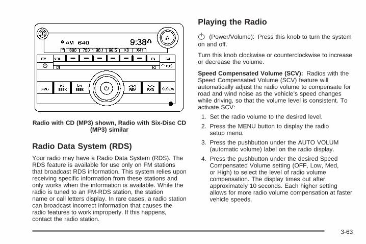
Radio Data System (RDS)Your radio may have a Radio Data System (RDS). TheRDS feature is available for use only on FM stationsthat broadcast RDS information. This system relies uponreceiving specific information from these stations andonly works when the information is available. While theradio is tuned to an FM-RDS station, the stationname or call letters display. In rare cases, a radio stationcan broadcast incorrect information that causes theradio features to work improperly. If this happens,contact the radio station.
Playing the Radio
O (Power/Volume): Press this knob to turn the systemon and off.
Turn this knob clockwise or counterclockwise to increaseor decrease the volume.
Speed Compensated Volume (SCV): Radios with theSpeed Compensated Volume (SCV) feature willautomatically adjust the radio volume to compensate forroad and wind noise as the vehicle’s speed changeswhile driving, so that the volume level is consistent. Toactivate SCV:
1. Set the radio volume to the desired level.
2. Press the MENU button to display the radiosetup menu.
3. Press the pushbutton under the AUTO VOLUM(automatic volume) label on the radio display.
4. Press the pushbutton under the desired SpeedCompensated Volume setting (OFF, Low, Med,or High) to select the level of radio volumecompensation. The display times out afterapproximately 10 seconds. Each higher settingallows for more radio volume compensation at fastervehicle speeds.
Radio with CD (MP3) shown, Radio with Six-Disc CD(MP3) similar
3-63
Finding a StationBAND: Press this button to switch between FM1 andFM2, AM, or XM™ (if equipped). The selection displays.
f (Tune): Turn to select radio stations.
© SEEK ¨: Press the arrows to go to the previous orto the next station and stay there.
To scan stations, press and hold either arrow for a fewseconds until a beep sounds. The radio goes to a station,plays for a few seconds, then goes on to the next station.Press either arrow again to stop scanning.
The radio only seeks and scans stations with a strongsignal that are in the selected band.
4 (Information) (Radio with CD (Base)): Press to switchthe display between the radio station frequency and thetime. While the ignition is off, press this button to displaythe time.
4 (Information) (XM™ Satellite Radio Service, MP3, andRDS Features): Press to display additional textinformation related to the current FM-RDS or XM™station, or MP3 song. A choice of additional information
such as: Channel, Song, Artist, and CAT (category) candisplay. Continue pressing to highlight the desired label,or press the pushbutton positioned under any one of thelabels and the information about that label displays.
While information is not available, No Info displays.
Setting Preset Stations (Radio withCD (Base))Up to 18 stations (six FM1, six FM2, and six AM), canbe programmed on the six numbered pushbuttons,by performing the following steps:
1. Turn the radio on.
2. Press BAND to select FM1, FM2, or AM.
3. Tune in the desired station.
4. Press and hold one of the six numberedpushbuttons for three seconds until a beep sounds.When that pushbutton is pressed and released,the station that was set, returns.
5. Repeat Steps 2 through 4 for each pushbutton.
3-64
Storing a Radio Station as a FavoriteDrivers are encouraged to set up their radio stationfavorites while the vehicle is parked. Tune to yourfavorite stations using the presets, favorites button, andsteering wheel controls if the vehicle has this feature.See Defensive Driving on page 4-2.
FAV (Favorites): A maximum of 36 stations can beprogrammed as favorites using the six pushbuttonspositioned below the radio station frequency labels andby using the radio favorites page button (FAV button).Press the FAV button to go through up to six pagesof favorites, each having six favorite stations availableper page. Each page of favorites can contain anycombination of AM, FM, or XM™ (if equipped) stations.To store a station as a favorite, perform the followingsteps:
1. Tune to the desired radio station.
2. Press the FAV button to display the page whereyou want the station stored.
3. Press and hold one of the six pushbuttons until abeep sounds. When that pushbutton is pressedand released, the station that was set, returns.
4. Repeat the steps for each pushbutton radio stationyou want stored as a favorite.
The number of favorites pages can be setup using theMENU button. To setup the number of favoritespages, perform the following steps:
1. Press the MENU button to display the radiosetup menu.
2. Press the pushbutton located below the FAV 1through 6 label.
3. Select the desired number of favorites pages bypressing the pushbutton located below thedisplayed page numbers.
4. Press the FAV button, or let the menu time out, toreturn to the original main radio screen showing theradio station frequency labels and to begin theprocess of programming your favorites for thechosen amount of numbered pages.
Setting the Tone (Bass/Treble) (Radiowith CD (Base))BASS/TREB (Bass/Treble): To adjust the bass ortreble, press the f knob or the BASS/TREBLEpushbutton until the desired tone control label displays.Turn the f knob clockwise or counterclockwise toincrease or decrease the setting. The current bass ortreble level displays. If a station’s frequency is weak, orhas static, decrease the treble.
EQ (Equalization): Press to adjust BASS and TREBLESettings.
3-65

Setting the Tone(Bass/Midrange/Treble)
BASS/MID/TREB (Bass, Midrange, or Treble): Toadjust bass, midrange, or treble, press the f knob untilthe tone control labels display. Continue pressing tohighlight the desired label, or press the pushbuttonpositioned under the desired label. Turn the f knobclockwise or counterclockwise to adjust the highlightedsetting. The highlighted setting can be adjusted bypressing either SEEK arrow, \ FWD (forward), ors REV (reverse) button until the desired levelsare obtained. If a station’s frequency is weak, or hasstatic, decrease the treble.
To quickly adjust bass, midrange, or treble to the middleposition, press the pushbutton positioned under theBASS, MID, or TREB label for more than two seconds.A beep sounds and the level adjusts to the middleposition.
To quickly adjust all tone and speaker controls to themiddle position, press the f knob for more thantwo seconds until a beep sounds.
EQ (Equalization): Press to select preset equalizationsettings.
To return to the manual mode, press until Manualdisplays or start to manually adjust the bass, midrange,or treble by pressing the f knob.
Adjusting the Speakers (Balance/Fade)(Radio with CD (Base))
` BAL/FADE (Balance/Fade): To adjust the balanceor fade, press this button or the f knob until the desiredspeaker control label displays. Turn the f knobclockwise or counterclockwise to adjust the setting.
Adjusting the Speakers (Balance/Fade)
BAL/FADE (Balance/Fade): To adjust balance orfade, press the f knob until the speaker control labelsdisplay. Continue pressing to highlight the desiredlabel, or press the pushbutton positioned under thedesired label. Turn the f knob clockwise orcounterclockwise to adjust the highlighted setting. Thehighlighted setting can be adjusted by pressingeither SEEK arrow, \ FWD, or s REV button untilthe desired levels are obtained.
3-66
To quickly adjust balance or fade to the middle position,press the pushbutton positioned under the BAL orFADE label for more than two seconds. A beep soundsand the level adjusts to the middle position.
To quickly adjust all speaker and tone controls to themiddle position, press the f knob for more thantwo seconds until a beep sounds.
Finding a Category (CAT) Station
CAT (Category): The CAT button is used to find XM™stations while the radio is in the XM™ mode. To findXM™ channels within a desired category, performthe following:
1. Press the BAND button until the XM™ frequency isdisplayed. Press the CAT button to display thecategory labels on the radio display. Continuepressing the CAT button until the desired categoryname displays.
2. Press either of the two buttons below the desiredcategory label to immediately tune to the firstXM™ station associated with that category.
3. Turn the tune knob, press the buttons below theright or left arrows displayed, or press the SEEKarrows to go to the previous or to the nextXM™ station within the selected category.
4. To exit the category search mode, press the FAVbutton or BAND button to display your favoritesagain.
Undesired XM™ categories can be removed throughthe setup menu. To remove an undesired category,perform the following:
1. Press the MENU button to display the radiosetup menu.
2. Press the pushbutton located below the XM CATlabel.
3. Turn the f knob to display the category you wantremoved.
4. Press the pushbutton located under the Removelabel until the category name along with the wordRemoved displays.
5. Repeat the steps to remove more categories.
Removed categories can be restored by pressing thepushbutton under the Add label when a removedcategory displays or by pressing the pushbutton underthe Restore All label.
Categories cannot be removed or added while thevehicle is moving faster than 5 mph (8 km/h).
3-67
Radio Messages
Calibration Error: The audio system has beencalibrated for your vehicle from the factory. If CalibrationError displays, it means that the radio has not beenconfigured properly for your vehicle and it mustbe returned to your dealer/retailer for service.
Loc or Locked: This message displays when theTHEFTLOCK® system has locked up the radio. Takethe vehicle to your dealer/retailer for service.
If any error occurs repeatedly or if an error cannot becorrected, contact your dealer/retailer.
XM™ Satellite Radio ServiceXM™ is a satellite radio service that is based in the 48contiguous United States and 10 Canadian provinces.XM™ Satellite Radio has a wide variety of programmingand commercial-free music, coast-to-coast, and indigital-quality sound. During your trial or when yousubscribe, you will get unlimited access to XM™ RadioOnline for when you are not in your vehicle. A servicefee is required to receive the XM™ service. Formore information, contact XM™ at www.xmradio.com orcall 1-800-929-2100 in the U.S. and www.xmradio.caor call 1-877-438-9677 in Canada.
Radio Messages for XM OnlySee XM Radio Messages on page 3-77 later in thissection for further detail.
Playing a CD (Single CD Player)Insert a CD partway into the slot, label side up. Theplayer pulls it in and the CD should begin playing.
Playing a CD(s) (Six-Disc CD Player)
LOAD ^: Press this button to load CDs into the CDplayer. This CD player holds up to six CDs.
To insert one CD, do the following:
1. Press and release the ^ button.
2. Wait for the message to insert the disc.
3. Load a CD. Insert the CD partway into the slot,label side up. The player pulls the CD in.
To insert multiple CDs, do the following:
1. Press and hold the ^ button for two seconds. Abeep sounds and Load All Discs displays.
2. Follow the displayed instruction on when to insertthe discs. The CD player takes up to six CDs.
3. Press the ^ button again to cancel loadingmore CDs.
3-68
If the ignition or radio is turned off, with a CD in theplayer, it stays in the player. When the ignition or radiois turned on, the CD starts playing where it stopped,if it was the last selected audio source.
When a CD is inserted, the CD symbol displays on theCD. As each new track starts to play, the tracknumber displays.
The CD player can play the smaller 3 inch (8 cm) singleCDs with an adapter ring. Full-size CDs and thesmaller CDs are loaded in the same manner.
Care of Your CDsIf playing a CD-R, the sound quality can be reduceddue to CD-R quality, the method of recording, the qualityof the music that has been recorded, and the way theCD-R has been handled. Handle them carefully.Store CD-R(s) in their original cases or other protectivecases and away from direct sunlight and dust. TheCD player scans the bottom surface of the disc. If thesurface of a CD is damaged, such as cracked, broken,or scratched, the CD does not play properly or notat all. Do not touch the bottom side of a CD whilehandling it; this could damage the surface. Pick up CDsby grasping the outer edges or the edge of the holeand the outer edge.
If the surface of a CD is soiled, take a soft, lint free clothor dampen a clean, soft cloth in a mild, neutral detergentsolution mixed with water, and clean it. Make sure thewiping process starts from the center to the edge.
If there is no apparent damage, try a known good CD.
Care of Your CD PlayerDo not add any label to a CD, it could get caught in theCD player. If a CD is recorded on a personal computerand a description label is needed, try labeling the top ofthe recorded CD with a marking pen instead.
The use of CD lens cleaners for CDs is not advised,due to the risk of contaminating the lens of the CD opticswith lubricants internal to the CD player mechanism.
Notice: If a label is added to a CD, or more than oneCD is inserted into the slot at a time, or an attemptis made to play scratched or damaged CDs, theCD player could be damaged. While using the CDplayer, use only CDs in good condition without anylabel, load one CD at a time, and keep the CDplayer and the loading slot free of foreign materials,liquids, and debris.
If an error displays, see “CD Messages” later in thissection.
3-69
Z EJECT: Press to eject CD(s). To eject the CD thatis currently playing, press and release this button. Abeep sounds and Ejecting Disc displays. Once the discis ejected, Remove Disc displays. The CD can beremoved. If the CD is not removed after severalseconds, the CD automatically pulls back into the playerand begins playing.
For the Six-Disc CD player, press and hold this buttonfor two seconds to eject all discs.
f (Tune): Turn to select tracks on the CD currentlyplaying.
© SEEK ¨: Press the left arrow to go to the start ofthe current track, if more than ten seconds haveplayed. Press the right arrow to go to the next track. Ifeither arrow is held, or pressed multiple times, the playercontinues moving backward or forward through thetracks on the CD.
s REV (Reverse): Press and hold to reverseplayback quickly. You will hear sound at a reducedvolume. Release to resume playing the track. Theelapsed time of the track displays.
\ FWD (Fast Forward): Press and hold to advanceplayback quickly. You will hear sound at a reducedvolume. Release to resume playing the track. Theelapsed time of the track displays.
RDM (Random): With the random setting, you canlisten to the tracks in random, rather than sequentialorder, on one CD or all CDs in a six-disc CD player. Touse random on the Radio with CD (Base), do one ofthe following:
1. Press to play tracks from the CD you are listeningto in random order. The random icon displays.
2. Press again to turn off random play. The randomicon disappears from the display.
To use random on the Radio with CD (MP3) or theRadio with Six-Disc player, do one of the following:
• Press the CD/AUX button, or for a single CD player,insert a disc partway into the slot of the CD player.A RDM label displays.To play the tracks from the single CD in randomorder, press the pushbutton positioned under theRDM label until Random Current Disc displays.Press the pushbutton again to turn off random play.
• Press the CD/AUX button, or for a six-disc CDplayer, press and hold the LOAD ^ button. A beepsounds and Load All Discs displays. Insert one ormore discs partway into the slot of the CD player.To play tracks from all CDs loaded in a six-disc CDplayer in random order, press the pushbuttonpositioned under the RDM label until Randomize AllDiscs displays. Press the same pushbutton again toturn off random play.
3-70

RPT (Repeat): For Radios with CD (Base), one trackcan be repeated by using the repeat setting.
To repeat the track you are listening to, press andrelease the RPT button. An arrow symbol displays.Press RPT again to turn off repeat play.
4 (Information) (Radio with CD (Base)): Press to switchthe display between the track number, elapsed timeof the track, and the time. When the ignition is off, pressthis button to display the time.
BAND: Press to listen to the radio while a CD isplaying. The CD remains inside the radio for futurelistening.
CD/AUX (CD/Auxiliary): Press to play a CD whilelistening to the radio. The CD icon and a messageshowing disc and/or track number displays when a CDis in the player. Press again and the systemautomatically searches for an auxiliary input device,such as a portable audio player. If a portable audioplayer is not connected, “No Aux Input Device” displays.
Playing an MP3 CD-R or CD-RW DiscRadios with the MP3 feature are capable of playing anMP3 CD-R or CD-RW disc. For more information onhow to play an MP3 CD-R or CD-RW disc, see Using anMP3 on page 3-72 later in this section.
CD Messages
CHECK DISC: If an error message displays and/or theCD comes out, it could be for one of the followingreasons:
• It is very hot. When the temperature returns tonormal, the CD should play.
• You are driving on a very rough road. When theroad becomes smoother, the CD should play.
• The CD is dirty, scratched, wet, or upside down.
• The air is very humid. If so, wait about an hour andtry again.
• There could have been a problem while burningthe CD.
• The label could be caught in the CD player.
If the CD is not playing correctly, for any other reason,try a known good CD.
If any error occurs repeatedly or if an error cannot becorrected, contact your dealer/retailer. If the radiodisplays an error message, write it down and provide itto your dealer/retailer while reporting the problem.
3-71
Using the Auxiliary Input JackYour radio system has an auxiliary input jack located onthe lower right side of the faceplate. This is not anaudio output; do not plug the headphone set into thefront auxiliary input jack. You can however, connect anexternal audio device such as an iPod, laptopcomputer, MP3 player, CD changer, or cassette tapeplayer, etc. to the auxiliary input jack for use as anothersource for audio listening.
Drivers are encouraged to set up any auxiliary devicewhile the vehicle is in PARK (P). See Defensive Drivingon page 4-2 for more information on driver distraction.
To use a portable audio player, connect a 3.5 mm(1/8 inch) cable to the radio’s front auxiliary input jack.When a device is connected, press the radio CD/AUXbutton to begin playing audio from the device overthe vehicle speakers.
O (Power/Volume): Turn clockwise orcounterclockwise to increase or decrease the volume ofthe portable player. Additional volume adjustmentsmight need to be made from the portable device.
BAND: Press to listen to the radio while a portable audiodevice is playing. The portable audio device continues toplay, so you might want to stop it or turn it off.
CD/AUX (CD/Auxiliary): Press to play a CD while aportable audio device is playing. Press again andthe system begins to play audio from the connectedportable audio player. If a portable audio player is notconnected, “No Aux Input Device” displays.
Using an MP3
MP3 CD-R or CD-RW DiscThe radio plays MP3 files that were recorded on a CD-Ror CD-RW disc. The files can be recorded with thefollowing fixed bit rates: 32 kbps, 40 kbps, 56 kbps,64 kbps, 80 kbps, 96 kbps, 112 kbps, 128 kbps,160 kbps, 192 kbps, 224 kbps, 256 kbps, and 320 kbps ora variable bit rate. Song title, artist name, and album candisplay when recorded using ID3 tags version 1 and 2.
Compressed AudioThe radio also plays discs that contain bothuncompressed CD audio (.CDA files) and MP3 files. Bydefault the radio reads only the uncompressed audioand ignores the MP3 files. Pressing the CAT (category)button toggles between compressed and uncompressedaudio format.
3-72

MP3 FormatIf you burn your own MP3 disc on a personal computer:
• Make sure the MP3 files are recorded on a CD-Ror CD-RW disc.
• Do not mix standard audio and MP3 files onone disc.
• Make sure the CD does not have more than amaximum of 50 folders, 50 playlists, and 255 files toread and play.
• Create a folder structure that makes it easy to findsongs while driving. Organize songs by albumsusing one folder for each album. Each folderor album should contain 18 songs or less.
• Avoid subfolders. The system can support up to8 subfolders deep, however, keep the totalnumber of folders to a minimum in order to reducethe complexity and confusion in trying to locatea particular folder during playback.
• Make sure playlists have a .mp3 or .wpl extension(other file extensions might not work).
• Minimize the length of the file, folder, or playlistnames. Long file, folder, or playlist names, or acombination of a large number of files and folders,or playlists can cause the player to be unable toplay up to the maximum number of files, folders,playlists, or sessions. If you wish to play alarge number of files, folders, playlists, or sessions,minimize the length of the file, folder, or playlistname. Long names also take up more space on thedisplay, and might not fully display.
• Finalize the audio disc before you burn it. Trying toadd music to an existing disc can cause the discnot to function in the player.
Playlists can be changed by using the previous andnext folder buttons, the tuner knob, or the seek buttons.An MP3 CD-R or CD-RW that was recorded using nofile folders can also be played. If a CD-R or CD-RWcontains more than the maximum of 50 folders,50 playlists, and 255 files, the player lets you accessand navigate up to the maximum, but all items over themaximum are not accessible.
3-73

Root DirectoryThe root directory of the CD-R or CD-RW is treated as afolder. If the root directory has compressed audio files,the directory displays as F1 ROOT. All files containeddirectly under the root directory are accessed prior to anyroot directory folders. However, playlists (Px) are alwaysaccessed before root folders or files.
Empty Directory or FolderIf a root directory or a folder exists somewhere in thefile structure that contains only folders/subfolders and nocompressed files directly beneath them, the playeradvances to the next folder in the file structurethat contains compressed audio files. The empty folderdoes not display.
No FolderWhen the CD-R or CD-RW contains only compressedfiles, the files are located under the root folder. The nextand previous folder functions are not displayed on aCD-R or CD-RW that was recorded without folders orplaylists. When displaying the name of the folderthe radio displays ROOT.
When the CD-R or CD-RW contains only playlists andcompressed audio files, but no folders, all files arelocated under the root folder. The folder down and thefolder up buttons search playlists (Px) first and thengoes to the root folder. When the radio displaysthe name of the folder, the radio displays ROOT.
Order of PlayTracks recorded to the CD-R or CD-RW are played inthe following order:
• Play begins from the first track in the first playlistand continues sequentially through all tracks ineach playlist. When the last track of the last playlisthas played, play continues from the first track ofthe first playlist.
• Play begins from the first track in the first folder andcontinues sequentially through all tracks in eachfolder. When the last track of the last folderhas played, play continues from the first track of thefirst folder.
When play enters a new folder, the display does notautomatically show the new folder name unlessthe folder mode was chosen as the default display. Thenew track name displays.
3-74

File System and NamingThe song name that displays is the song name that iscontained in the ID3 tag. If the song name is not presentin the ID3 tag, then the radio displays the file namewithout the extension (such as .mp3) as the track name.
Track names longer than 32 characters or four pagesare shortened. Parts of words on the last page oftext and the extension of the filename does not display.
Preprogrammed PlaylistsPreprogrammed playlists that were created usingWinAmp™, MusicMatch™, or Real Jukebox™ software,can be accessed, however, they cannot be editedusing the radio. These playlists are treated as specialfolders containing compressed audio song files.
Playing an MP3Insert a CD-R or CD-RW partway into the slot (SingleCD Player), or press the load button and wait forthe message to insert disc (Six-Disc CD Player), labelside up. The player pulls it in, and the CD-R or CD-RWshould begin playing.
If the ignition or radio is turned off with a CD-R orCD-RW in the player, it stays in the player. When theignition or radio is turned on, the CD-R starts toplay where it stopped, if it was the last selected audiosource.
As each new track starts to play, the track number andsong title displays.
Z EJECT: Press this button to eject CD-R(s) orCD-RW(s). To eject the CD-R or CD-RW that is currentlyplaying, press and release this button. A beep soundsand Ejecting Disc displays. Once the disc is ejected,Remove Disc displays. The CD-R or CD-RW canbe removed. If the CD-R or CD-RW is not removed,after several seconds, the CD-R or CD-RWautomatically pulls back into the player and beginsplaying. For the Six-Disc CD player, press and hold thisbutton for two seconds to eject all discs.
f (Tune): Turn this knob to select MP3 files on theCD-R or CD-RW currently playing.
© SEEK ¨: Press the left SEEK arrow to go to thestart of the current MP3 file, if more than ten secondshave played. Press the right SEEK arrow to go tothe next MP3 file. If either SEEK arrow is held orpressed multiple times, the player continues movingbackward or forward through MP3 files on the CD.
Sc (Previous Folder): Press the pushbuttonpositioned under the Folder label to go to the first trackin the previous folder.
3-75
cT (Next Folder): Press the pushbutton positionedunder the Folder label to go to the first track in thenext folder.
s REV (Reverse): Press and hold this button toreverse playback quickly within an MP3 file. Youwill hear sound at a reduced volume. Release this buttonto resume playing the file. The elapsed time of the filedisplays.
\ FWD (Fast Forward): Press and hold this button toadvance playback quickly within an MP3 file. You willhear sound at a reduced volume. Release this button toresume playing the file. The elapsed time of the filedisplays.
RDM (Random): With the random setting, MP3 files onthe CD-R or CD-RW can be played in random, ratherthan sequential order, on one CD-R/CD-RW or all discsin a six-disc CD player. To use random, do one ofthe following:
1. To play MP3 files in random order from the CD-Ror CD-RW that is currently playing, press thepushbutton positioned under the RDM label untilRandom Current Disc displays. Press the samepushbutton again to turn off random play.
2. To play songs from all CDs loaded in a six-disc CDplayer in random order, press the pushbuttonpositioned under the RDM label until Randomize AllDiscs displays. Press the same pushbutton againto turn off random play.
h (Music Navigator): Use the music navigatorfeature to play MP3 files on the CD-R or CD-RW inorder by artist or album. Press the pushbutton locatedbelow the music navigator label. The player scansthe disc to sort the files by artist and album ID3tag information. It can take several minutes to scan thedisc depending on the number of MP3 files recordedto the CD-R or CD-RW. The radio can begin playingwhile it is scanning the disc in the background. When thescan is finished, the CD-R or CD-RW begins playingagain.
Once the disc has been scanned, the player defaults toplaying MP3 files in order by artist. The current artistplaying is shown on the second line of the displaybetween the arrows. Once all songs by that artist areplayed, the player moves to the next artist inalphabetical order on the CD-R/CD-RW and beginsplaying MP3 files by that artist. If you want to listen toMP3 files by another artist, press the pushbutton locatedbelow either arrow button. The CD goes to the next orprevious artist in alphabetical order. Continue pressingeither button until the desired artist displays.
3-76
To change from playback by artist to playback byalbum, press the pushbutton located below the Sort Bylabel. From the sort screen, push one of the buttonsbelow the album button. Press the pushbutton below theback label to return to the main music navigatorscreen. The album name displays on the second linebetween the arrows and songs from the currentalbum and begins to play. Once all songs from thatalbum are played, the player moves to the next albumin alphabetical order on the CD-R or CD-RW and beginsplaying MP3 files from that album.
To exit music navigator mode, press the pushbuttonbelow the Back label to return to normal MP3 playback.
BAND: Press this button to listen to the radio whilea CD is playing. The CD remains inside the radiofor future listening.
CD/AUX (CD/Auxiliary): Press this button to play a CDwhile listening to the radio. The CD icon and amessage showing disc and/or track number displayswhile a CD is in the player. Press this button again andthe system automatically searches for an auxiliaryinput device such as a portable audio player. If aportable audio player is not connected, “No Aux InputDevice” displays.
XM Radio Messages
XL (Explicit Language Channels): These channels, orany others, can be blocked at a customer’s request,by calling 1-800-852-XMXM (9696).
XM Updating: The encryption code in the receiver isbeing updated, and no action is required. This processshould take no longer than 30 seconds.
No XM Signal: The system is functioning correctly, butthe vehicle is in a location that is blocking the XM™signal. When you move into an open area, the signalshould return.
Loading XM: The audio system is acquiring andprocessing audio and text data. No action is needed.This message should disappear shortly.
Channel Off Air: This channel is not currently inservice. Tune to another channel.
Channel Unavail: This previously assigned channel isno longer assigned. Tune to another station. If thisstation was one of the presets, choose another stationfor that preset button.
No Artist Info: No artist information is available at thistime on this channel. The system is working properly.
3-77

No Title Info: No song title information is available atthis time on this channel. The system is workingproperly.
No CAT Info: No category information is available atthis time on this channel. The system is workingproperly.
No Information: No text or informational messages areavailable at this time on this channel. The system isworking properly.
CAT Not Found: There are no channels available forthe selected category. The system is working properly.
XM TheftLocked: The XM receiver in the vehiclecould have previously been in another vehicle. Forsecurity purposes, XM™ receivers cannot be swappedbetween vehicles. If this message appears afterhaving your vehicle serviced, check with yourdealer/retailer.
XM Radio ID: If tuned to channel 0, this messagealternates with the XM Radio eight digit radio ID label.This label is needed to activate the service.
Unknown: If this message is received when tuned tochannel 0, there could be a receiver fault. Consultwith your dealer/retailer.
Check XM Receivr: If this message does not clearwithin a short period of time, the receiver could have afault. Consult with your dealer/retailer.
XM Not Available: If this message does not clearwithin a short period of time, the receiver could have afault. Consult with your dealer/retailer.
Theft-Deterrent FeatureTHEFTLOCK® is designed to discourage theft of yourvehicle’s radio. The feature works automatically bylearning a portion of the Vehicle Identification Number(VIN). If the radio is moved to a different vehicle, it doesnot operate and LOC, LOCK, or LOCKED coulddisplay.
With THEFTLOCK® activated, the radio does notoperate if stolen.
3-78
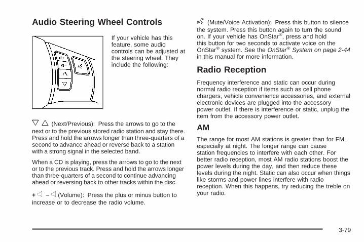
Audio Steering Wheel Controls
If your vehicle has thisfeature, some audiocontrols can be adjusted atthe steering wheel. Theyinclude the following:
xw (Next/Previous): Press the arrows to go to thenext or to the previous stored radio station and stay there.Press and hold the arrows longer than three-quarters of asecond to advance ahead or reverse back to a stationwith a strong signal in the selected band.
When a CD is playing, press the arrows to go to the nextor to the previous track. Press and hold the arrows longerthan three-quarters of a second to continue advancingahead or reversing back to other tracks within the disc.
+ e − e (Volume): Press the plus or minus button toincrease or to decrease the radio volume.
g (Mute/Voice Activation): Press this button to silencethe system. Press this button again to turn the soundon. If your vehicle has OnStar®, press and holdthis button for two seconds to activate voice on theOnStar® system. See the OnStar® System on page 2-44in this manual for more information.
Radio ReceptionFrequency interference and static can occur duringnormal radio reception if items such as cell phonechargers, vehicle convenience accessories, and externalelectronic devices are plugged into the accessorypower outlet. If there is interference or static, unplug theitem from the accessory power outlet.
AMThe range for most AM stations is greater than for FM,especially at night. The longer range can causestation frequencies to interfere with each other. Forbetter radio reception, most AM radio stations boost thepower levels during the day, and then reduce theselevels during the night. Static can also occur when thingslike storms and power lines interfere with radioreception. When this happens, try reducing the treble onyour radio.
3-79

FM StereoFM stereo gives the best sound, but FM signals onlyreach about 10 to 40 miles (16 to 65 km). Tall buildingsor hills can interfere with FM signals, causing thesound to fade in and out.
XM™ Satellite Radio ServiceXM™ Satellite Radio Service gives digital radioreception from coast-to-coast in the 48 contiguousUnited States, and in Canada. Just as with FM,tall buildings or hills can interfere with satellite radiosignals, causing the sound to fade in and out. Inaddition, traveling or standing under heavy foliage,bridges, garages, or through tunnels could cause loss ofthe XM signal for a period of time. The radio maydisplay NO XM SIGNAL to indicate interference.
Fixed Mast AntennaThis type of antenna is called a fixed mast antenna. It ismounted at the center of the roof, just behind thewindshield.
The mast antenna can withstand most car washeswithout being damaged. If the mast should ever becomeslightly bent, straighten it out by hand. If the mast isbadly bent, replace it.
Check occasionally to make sure the mast is stilltightened to the roof. If tightening is required, tightenby hand.
If you are putting a protective cover over the vehicle,remove the mast by hand.
XM™ Satellite Radio AntennaSystemThe XM™ Satellite Radio antenna is located at the rearof the vehicle. Keep this antenna clear of snow andice build up for clear radio reception.
If your vehicle has a sunroof, the performance of theXM™ system may be affected if the sunroof is open.
If your vehicle has a roof rack, loading items ontothe roof of your vehicle can interfere with theperformance of the XM™ system. Make sure the XM™Satellite Radio antenna is not obstructed.
3-80

Your Driving, the Road, and Your Vehicle ..........4-2Defensive Driving ...........................................4-2Drunk Driving .................................................4-2Control of a Vehicle ........................................4-3Braking .........................................................4-3Antilock Brake System (ABS) ...........................4-5Braking in Emergencies ...................................4-6Traction Control System (TCS) .........................4-6Enhanced Traction System (ETS) .....................4-9Limited-Slip Differential ..................................4-10Electronic Stability Control (ESC) ....................4-10Steering ......................................................4-13Off-Road Recovery .......................................4-15Passing .......................................................4-16Loss of Control .............................................4-16
Driving at Night ............................................4-18Driving in Rain and on Wet Roads ..................4-18Before Leaving on a Long Trip .......................4-20Highway Hypnosis ........................................4-20Hill and Mountain Roads ................................4-20Winter Driving ..............................................4-22If Your Vehicle is Stuck in Sand, Mud, Ice,
or Snow ...................................................4-26Rocking Your Vehicle to Get It Out .................4-26Loading Your Vehicle ....................................4-27
Towing ..........................................................4-32Towing Your Vehicle .....................................4-32Recreational Vehicle Towing ...........................4-32Towing a Trailer (Manual Transaxle) ................4-34Towing a Trailer (Automatic Transaxle) ............4-34
Section 4 Driving Your Vehicle
4-1

Your Driving, the Road, andYour Vehicle
Defensive DrivingDefensive driving means “always expect theunexpected.” The first step in driving defensively is towear your safety belt — See Safety Belts: They Are forEveryone on page 1-12.
{CAUTION:
Assume that other road users (pedestrians,bicyclists, and other drivers) are going to becareless and make mistakes. Anticipate whatthey might do and be ready. In addition:
• Allow enough following distance betweenyou and the driver in front of you.
• Focus on the task of driving.
Driver distraction can cause collisionsresulting in injury or possible death. Thesesimple defensive driving techniques couldsave your life.
Drunk Driving
{CAUTION:
Drinking and then driving is very dangerous.Your reflexes, perceptions, attentiveness, andjudgment can be affected by even a smallamount of alcohol. You can have a serious — oreven fatal — collision if you drive after drinking.Do not drink and drive or ride with a driver whohas been drinking. Ride home in a cab; or if youare with a group, designate a driver who will notdrink.
Death and injury associated with drinking and driving isa global tragedy.
Alcohol affects four things that anyone needs to drive avehicle: judgment, muscular coordination, vision, andattentiveness.
4-2

Police records show that almost 40 percent of all motorvehicle-related deaths involve alcohol. In most cases,these deaths are the result of someone who wasdrinking and driving. In recent years, more than17,000 annual motor vehicle-related deaths have beenassociated with the use of alcohol, with about250,000 people injured.
For persons under 21, it is against the law in everyU.S. state to drink alcohol. There are good medical,psychological, and developmental reasons forthese laws.
The obvious way to eliminate the leading highwaysafety problem is for people never to drink alcohol andthen drive.
Medical research shows that alcohol in a person’ssystem can make crash injuries worse, especiallyinjuries to the brain, spinal cord, or heart. This meansthat when anyone who has been drinking — driveror passenger — is in a crash, that person’s chance ofbeing killed or permanently disabled is higher than if theperson had not been drinking.
Control of a VehicleThe following three systems help to control your vehiclewhile driving — brakes, steering, and accelerator. Attimes, as when driving on snow or ice, it is easy to askmore of those control systems than the tires androad can provide. Meaning, you can lose control of yourvehicle. See Traction Control System (TCS) onpage 4-6,Enhanced Traction System (ETS) on page 4-9,and Electronic Stability Control (ESC) on page 4-10.
Adding non-dealer/non-retailer accessories canaffect your vehicle’s performance. See Accessories andModifications on page 5-3.
BrakingSee Brake System Warning Light on page 3-35.
Braking action involves perception time and reactiontime. First, you have to decide to push on the brakepedal. That is perception time. Then you have to bringup your foot and do it. That is reaction time.
4-3

Average reaction time is about three-fourths of asecond. But that is only an average. It might be lesswith one driver and as long as two or three seconds ormore with another. Age, physical condition, alertness,coordination, and eyesight all play a part. So do alcohol,drugs, and frustration. But even in three-fourths of asecond, a vehicle moving at 60 mph (100 km/h) travels66 feet (20 m). That could be a lot of distance in anemergency, so keeping enough space betweenyour vehicle and others is important.
And, of course, actual stopping distances vary greatlywith the surface of the road, whether it is pavementor gravel; the condition of the road, whether it iswet, dry, or icy; tire tread; the condition of the brakes;the weight of the vehicle; and the amount of brakeforce applied.
Avoid needless heavy braking. Some people drive inspurts — heavy acceleration followed by heavybraking — rather than keeping pace with traffic. This isa mistake. The brakes might not have time to coolbetween hard stops. The brakes will wear out muchfaster if you do a lot of heavy braking. If you keep pacewith the traffic and allow realistic following distances,you will eliminate a lot of unnecessary braking.That means better braking and longer brake life.
If your vehicle’s engine ever stops while you are driving,brake normally but do not pump the brakes. If you do,the pedal could get harder to push down. If theengine stops, you will still have some power brakeassist. But you will use it when you brake. Once thepower assist is used up, it can take longer to stop andthe brake pedal will be harder to push.
If your vehicle has Electronic Stability Control (ESC)and the 2.0L turbocharged engine, it also has ahydraulic brake boost feature which supplements thepower brake system to maintain consistent brakeperformance under conditions of low brake boostervacuum. Low brake booster vacuum conditionscan include initial start up after the vehicle has beenparked for several hours, very frequent brake stops, orhigh altitude driving. When hydraulic brake boost isactive, you might feel minor brake pulsation ormovement but this is normal. If brake pedal feel changesor the brake pedal feels hard to push, you might notbe receiving the intended brake boost and the SVCBRAKE SYSTEM DIC message may be displayed.
Adding non-dealer/non-retailer accessories can affectyour vehicle’s performance. See Accessories andModifications on page 5-3.
4-4
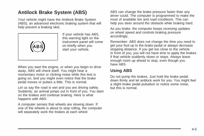
Antilock Brake System (ABS)Your vehicle might have the Antilock Brake System(ABS), an advanced electronic braking system that willhelp prevent a braking skid.
If your vehicle has ABS,this warning light on theinstrument panel will comeon briefly when youstart your vehicle.
When you start the engine, or when you begin to driveaway, ABS will check itself. You might hear amomentary motor or clicking noise while this test isgoing on, and you might even notice that the brakepedal moves or pulses a little. This is normal.
Let us say the road is wet and you are driving safely.Suddenly, an animal jumps out in front of you. You slamon the brakes and continue braking. Here is whathappens with ABS:
A computer senses that wheels are slowing down. Ifone of the wheels is about to stop rolling, the computerwill separately work the brakes at each wheel.
ABS can change the brake pressure faster than anydriver could. The computer is programmed to make themost of available tire and road conditions. This canhelp you steer around the obstacle while braking hard.
As you brake, the computer keeps receiving updateson wheel speed and controls braking pressureaccordingly.
Remember: ABS does not change the time you need toget your foot up to the brake pedal or always decreasestopping distance. If you get too close to the vehiclein front of you, you will not have time to apply the brakesif that vehicle suddenly slows or stops. Always leaveenough room up ahead to stop, even though youhave ABS.
Using ABSDo not pump the brakes. Just hold the brake pedaldown firmly and let antilock work for you. You might feela slight brake pedal pulsation or notice some noise,but this is normal.
4-5

Braking in EmergenciesAt some time, nearly every driver gets into a situationthat requires hard braking.
If you have ABS, you can steer and brake at the sametime. However, if you do not have ABS, your firstreaction — to hit the brake pedal hard and hold itdown — might be the wrong thing to do. Your wheelscan stop rolling. Once they do, the vehicle cannotrespond to your steering. Momentum will carry it inwhatever direction it was headed when the wheelsstopped rolling. That could be off the road, into the verything you were trying to avoid, or into traffic.
If you do not have ABS, use a “squeeze” brakingtechnique. This will give you maximum braking whilemaintaining steering control. You can do this by pushingon the brake pedal with steadily increasing pressure.
In an emergency, you will probably want to squeeze thebrakes hard without locking the wheels. If you hear orfeel the wheels sliding, ease off the brake pedal.This will help you retain steering control. If you do haveABS, it is different. See Antilock Brake System (ABS)on page 4-5.
In many emergencies, steering can help you more thaneven the very best braking.
Brake AssistIf your vehicle has ESC with ABS, it also has a brakeassist feature that responds to emergency brakingby generating additional pressure and engagingthe ABS. When this happens, the brake pedal will feeleasier to push. Just hold the brake pedal downfirmly and let the system work for you. You might feelthe brakes vibrate or notice some noise, but this isnormal. The brakes will return to normal operation afterthe brake pedal is released.
Brake assist cannot compensate for unsafe drivingpractices and braking effectiveness, itself, depends onthe condition of the road, tires, and brakes andvehicle mass.
Traction Control System (TCS)Your vehicle may have a Traction Control System (TCS)that limits wheel spin. This is especially useful inslippery road conditions. The system operates only if itsenses that the wheels are spinning too much orare beginning to lose traction. When this happens, thesystem works the front brakes and reduces enginepower by closing the throttle and managing engine sparkto limit wheel spin.
If your vehicle has TCS, there is a ESC/TCS buttonlocated on the instrument panel.
4-6

This light flashes while thetraction control system islimiting wheel spin.
You may feel or hear the system working, but this isnormal.
See Electronic Stability Control (ESC)/Traction ControlSystem (TCS) Indicator/Warning Light on page 3-37for more information.
If your vehicle is in cruise control while TCS begins tolimit wheel spin, the cruise control will automaticallydisengage. When road conditions allow you to safelyuse it again, the cruise control can be re-engaged. SeeTurn Signal/Multifunction Lever on page 3-7.
When this light is on andeither the SERVICETRACTION or TRACTIONOFF message isdisplayed, the system willnot limit wheel spin.
Adjust your driving accordingly. See DIC Warnings andMessages on page 3-48 for more information.
The Traction Control System is automatically enabledwhenever you start your vehicle. To limit wheelspin, especially in slippery road conditions, you shouldalways leave the system enabled. You can turn TCSoff if you ever need to.
It is recommended to leave the system on for normaldriving conditions, but it may be necessary to turn thesystem off if your vehicle is stuck in sand, mud, ice orsnow, and you want to “rock” your vehicle to attempt tofree it. It may also be necessary to turn off the systemwhen driving in extreme off-road conditions where highwheel spin is required. See If Your Vehicle is Stuck inSand, Mud, Ice, or Snow on page 4-26.
To turn the system off oron, press and release theESC/TCS button locatedon the instrument panel.
The DIC displays the appropriate message as describedpreviously when the button is pressed.
4-7

Traction Control OperationTraction control limits wheel spin by reducing enginepower to the wheels (engine speed management)and by applying brakes to each individual wheel(brake-traction control) as necessary.
The traction control system is enabled automaticallywhen you start your vehicle, and it will activate and flashthe ESC/TCS light and display the LOW TRACTIONmessage if it senses that any of the wheels are spinningor beginning to lose traction while driving. For moreinformation on the LOW TRACTION message,see Driver Information Center (DIC) on page 3-46.
Notice: If you allow the wheel(s) of one axle to spinexcessively while the ESC/TCS, ABS and Brakewarning lights and the SERVICE ESC and/orSERVICE TRACTION messages are displayed, youcould damage the differential. The repairs would notbe covered by your warranty. Reduce enginepower and do not spin the wheel(s) excessivelywhile these lights and this message are displayed.
Notice: When traction control is turned off, orCompetitive Driving Mode is active, it is possible tolose traction. If you attempt to shift with the frontwheels spinning with a loss of traction, it is possibleto cause damage to the transmission. Do notattempt to shift when the front wheels do not havetraction. Damage caused by misuse of the vehicleis not covered. See your warranty book foradditional information.
The traction control system may activate on dry orrough roads or under conditions such as heavyacceleration while turning or abrupt upshifts/downshiftsof the transmission. When this happens, you maynotice a reduction in acceleration, or may hear a noiseor vibration. This is normal.
If your vehicle is in cruise control while the systemactivates, the ESC/TCS light flashes and the cruisecontrol automatically disengages. When road conditionsallow you to use cruise control again, you may re-engagethe cruise control. See Cruise Control on page 3-12.
Adding non-dealer/non-retailer accessories can affectyour vehicle’s performance. See Accessories andModifications on page 5-3 for more information.
4-8

Enhanced Traction System (ETS)Your vehicle may have an Enhanced TractionSystem (ETS) that limits wheel spin. This is especiallyuseful in slippery road conditions. The system operatesonly if it senses that one or both of the front wheels arespinning or beginning to lose traction. When thishappens, the system reduces engine power and may alsoupshift the transmission to limit wheel spin. You may feelor hear the system working, but this is normal.
If your vehicle has ETS, there is not an ESC/TCSbutton on the instrument panel. To turn the systemoff, shift to LOW (L) or REVERSE (R). There is moreinformation about how to turn the system off later inthis section.
A LOW TRACTION message will appear on the DriverInformation Center (DIC) when the traction controlsystem is actively limiting wheel spin. Slippery roadconditions may exist if this message is displayed,so adjust your driving accordingly.
If your vehicle is in cruise control when the ETS beginsto limit wheel spin, the cruise control will automaticallydisengage. When road conditions allow you to safelyuse it again, you may re-engage the cruise control. SeeCruise Control on page 3-12.
When the system is on,this warning light will comeon to let you knowthere’s a problem.
The ETS warning light may come on for the followingreasons:
• If you turn the system off by moving the shift leverto LOW (L), the warning light will come on andstay on. To turn the system back on, move the shiftlever back to a position other than LOW (L). Thewarning light should go off.
• The warning light will come on when you set yourparking brake with the engine running, and it willstay on if your parking brake does not release fully.If the transmission shift lever is in any positionother than LOW (L)and the warning light stays onafter your parking brake is fully released, itmeans there is a problem with the system.
• If the traction control system is affected by anengine related problem, the system will turn off andthe warning light will come on.
4-9

If the warning light stays on, or comes on when you’redriving, there may be a problem with your ETS andyour vehicle may need service. When this warning lightis on, the system will not limit wheel spin. Adjustyour driving accordingly.
If the ETS warning light comes on and stays on for anextended period of time when the transmission shiftlever is in any position other than LOW (L), your vehicleneeds service.
To limit wheel spin, especially in slippery roadconditions, you should always leave the ETS on. Butyou can turn the system off if you prefer.
To turn the system off, shift to LOW (L) or REVERSE (R).
When you turn the system off, the ETS warning light willcome on and stay on when the gear shift is in LOW (L).The warning light will not come on when the gear shift isin REVERSE (R). If the ETS is limiting wheel spin whenyou shift to LOW (L) or REVERSE (R) to turn the systemoff, the warning light will come on in LOW (L). But thesystem won’t turn off right away. It will wait until there’s nolonger a current need to limit wheel spin.
You can turn the system back on at any time by shifting toAUTOMATIC OVERDRIVE (D) or INTERMEDIATE (I).The ETS warning light should go off.
Adding non-dealer/non-retailer accessories can affectyour vehicle’s performance. See Accessories andModifications on page 5-3 for more information.
Limited-Slip DifferentialYour vehicle may have this feature. A limited-sliptransmission can give you additional traction on snow,mud, ice, sand or gravel. It works like a standardtransmission most of the time, but when one of the frontwheels loses traction, this feature will allow the wheelwith traction to move the vehicle. The limited slip designhas minimal impact to the steering feel, but booststhe traction performance under all conditions.
Electronic Stability Control (ESC)Your vehicle may have an Electronic StabilityControl (ESC) system which combines antilock brake,and traction and stability control systems that helpthe driver maintain directional control of the vehicle inmost driving conditions.
When the vehicle is started and begins to move, thesystem performs several diagnostic checks to ensurethere are no problems. You may hear or feel the systemworking. This is normal and does not mean there is aproblem with your vehicle. The system should initializebefore the vehicle reaches 20 mph (32 km/h).
If the system fails to turn on or activate, the ESC/TCSlight comes on, and the ESC OFF and/or SERVICE ESCmessage displays.
4-10

For more information, see Driver InformationCenter (DIC) on page 3-46 and Electronic StabilityControl (ESC)/Traction Control System (TCS)Indicator/Warning Light on page 3-37.
This light flashes on theinstrument panel clusterwhen the ESC systemis on and activated.
ESC activates when the computer senses a discrepancybetween your intended path and the direction the vehicleis actually travelling. ESC selectively applies brakingpressure at any one of the vehicle’s brakes to help steerthe vehicle in the direction which you are steering.
When the system activates, an ESC ACTIVE messagedisplays on the Driver Information Center. See DICWarnings and Messages on page 3-48. This light alsoflashes on the instrument panel cluster when theESC system is on and activated. You may also hear anoise or feel vibration in the brake pedal. This isnormal. Continue to steer the vehicle in the directionyou want it to go.
When the light is on solid and the message(s),SERVICE ESC, ESC OFF, or both display, the systemwill not assist the driver in maintaining directionalcontrol of the vehicle. Adjust your driving accordingly.See DIC Warnings and Messages on page 3-48.
The Electronic Stability Control (ESC) system isautomatically enabled whenever you start your vehicle.To assist the driver with vehicle directional control,especially in slippery road conditions, you should alwaysleave the system on. But, you can turn ESC off if youever need to.
If the vehicle is in cruise control when the systembegins to assist the driver maintain directional control ofthe vehicle, the ESC/TCS light will flash and thecruise control will automatically disengage. When roadconditions allow you to use cruise again, you mayre-engage the cruise control. See Cruise Control onpage 3-12.
The ESC/TCS buttonis located on theinstrument panel.
4-11

The traction control system can be turned off or back onby pressing the ESC/TCS button. To disable bothtraction control and ESC, press and hold the button fromfive to ten seconds.
When the ESC system is turned off, the TRACTIONOFF and ESC OFF messages appear, and theESC/TCS light comes on to warn the driver that bothtraction control and ESC are disabled.
It is recommended that the system remain on for normaldriving conditions, but it may be necessary to turn thesystem off if your vehicle is stuck in sand, mud, iceor snow, and you want to “rock” your vehicle to attemptto free it. It may also be necessary to turn off thesystem when driving in extreme off-road conditionswhere high wheel spin is required. See If Your Vehicleis Stuck in Sand, Mud, Ice, or Snow on page 4-26.
ESC may also turn off automatically if it determines thata problem exists with the system. The ESC OFF andSERVICE ESC messages and the ESC/TCS light comeson to warn the driver that ESC is disabled and requiresservice. If the problem does not clear after restartingthe vehicle, see your dealer/retailer for service. See DICWarnings and Messages on page 3-48 for moreinformation.
Adding non-dealer/non-retailer accessories can affectyour vehicle’s performance. See Accessories andModifications on page 5-3 for more information.
Competitive Driving ModeThe driver can select this optional handling mode bypressing the ESC/TCS button on the console two timeswithin a five second time period. COMPETITIVEMODE will be displayed in the DIC. See DIC Warningsand Messages on page 3-48.
Competitive Driving Mode allows the driver to have fullcontrol of the front wheels while the ESC systemhelps maintain directional control of the vehicle byselective brake application. The ESC/TCS light will beon and the traction control system will not be operating.Adjust your driving accordingly. This electronic stabilitycontrol mode is recommended only for use during closedtrack events and competitive driving venues.
When the ESC button is pressed again, or the vehicle isrestarted, the ESC and TCS will be turned back on.
Notice: When traction control is turned off, orCompetitive Driving Mode is active, it is possible tolose traction. If you attempt to shift with the frontwheels spinning with a loss of traction, it is possibleto cause damage to the transmission. Do notattempt to shift when the front wheels do not havetraction. Damage caused by misuse of the vehicleis not covered. See your warranty book foradditional information.
4-12
Launch ControlIf your vehicle has this feature, LAUNCH CONTROLdisplays after the COMPETITIVE MODE message, whenthe vehicle is stopped. Launch control is a form oftraction control, to control wheel spin while launchingthe vehicle during closed track events and competitivedriving venues. The system will exit to COMPETITIVEMODE after the vehicle is launched. See “CompetitiveDriving Mode” earlier in this section. The normal TractionControl System (TCS) will not be operating while inthe Competitive Driving mode and the TCS light on theinstrument panel cluster comes on. Adjust yourdriving accordingly. See DIC Warnings and Messageson page 3-48 for more information.
Steering
Electric Power SteeringIf the engine stalls while you are driving, the powersteering assist system will continue to operate until youare able to stop your vehicle. If you lose powersteering assist because the electric power steeringsystem is not functioning, you can steer, but it will takemore effort.
If you turn the steering wheel in either direction severaltimes until it stops, or hold the steering wheel in thestopped position for an extended amount of time, youmay notice a reduced amount of power steeringassist. The normal amount of power steering assistshould return shortly after a few normal steeringmovements.
The electric power steering system does not requireregular maintenance. If you suspect steering systemproblems and/or the POWER STEERING messagecomes on, contact your dealer/retailer for servicerepairs. See DIC Warnings and Messages on page 3-48.
Steering TipsIt is important to take curves at a reasonable speed.
A lot of the “driver lost control” accidents mentioned onthe news happen on curves. Here is why:
Experienced driver or beginner, each of us is subject tothe same laws of physics when driving on curves.The traction of the tires against the road surface makesit possible for the vehicle to change its path whenyou turn the front wheels. If there is no traction, inertiawill keep the vehicle going in the same direction. Ifyou have ever tried to steer a vehicle on wet ice, youwill understand this.
4-13

The traction you can get in a curve depends on thecondition of the tires and the road surface, the angle atwhich the curve is banked, and your speed. Whileyou are in a curve, speed is the one factor youcan control.
Suppose you are steering through a sharp curve.Then you suddenly apply the brakes. Both controlsystems — steering and braking — have to do their workwhere the tires meet the road. Unless you haveantilock brakes, adding the hard braking can demandtoo much of those places. You can lose control.
The same thing can happen if you are steering through asharp curve and you suddenly accelerate. Those twocontrol systems — steering and acceleration — canoverwhelm those places where the tires meet theroad and make you lose control. See Traction ControlSystem (TCS) on page 4-6, Enhanced TractionSystem (ETS) on page 4-9, and Electronic StabilityControl (ESC) on page 4-10.
What should you do if this ever happens? Ease up onthe brake or accelerator pedal, steer the vehicle the wayyou want it to go, and slow down.
Speed limit signs near curves warn that you shouldadjust your speed. Of course, the posted speedsare based on good weather and road conditions. Underless favorable conditions you will want to go slower.
If you need to reduce your speed as you approach acurve, do it before you enter the curve, while thefront wheels are straight ahead.
Try to adjust your speed so you can drive through thecurve. Maintain a reasonable, steady speed. Waitto accelerate until you are out of the curve, and thenaccelerate gently into the straightaway.
Adding non-dealer/non-retailer accessories can affectyour vehicle’s performance. See Accessories andModifications on page 5-3.
Steering in EmergenciesThere are times when steering can be more effective thanbraking. For example, you come over a hill and find atruck stopped in your lane, or a car suddenly pulls outfrom nowhere, or a child darts out from between parkedcars and stops right in front of you. You can avoid theseproblems by braking — if you can stop in time. Butsometimes you cannot; there is not room. That is the timefor evasive action — steering around the problem.
Your vehicle can perform very well in emergencies likethese. First apply the brakes — but, unless you haveantilock brakes, not enough to lock the wheels.See Braking on page 4-3. It is better to remove as muchspeed as you can from a possible collision. Thensteer around the problem, to the left or right dependingon the space available.
4-14

An emergency like this requires close attention and aquick decision. If you are holding the steering wheel atthe recommended 9 and 3 o’clock positions, youcan turn it a full 180 degrees very quickly withoutremoving either hand. But you have to act fast, steerquickly, and just as quickly straighten the wheelonce you have avoided the object.
The fact that such emergency situations are alwayspossible is a good reason to practice defensive drivingat all times and wear safety belts properly.
Off-Road RecoveryYou may find that your vehicle’s right wheels havedropped off the edge of a road onto the shoulder whileyou are driving.
If the level of the shoulder is only slightly below thepavement, recovery should be fairly easy. Ease off theaccelerator and then, if there is nothing in the way,steer so that your vehicle straddles the edge ofthe pavement. You can turn the steering wheel up toone-quarter turn until the right front tire contactsthe pavement edge. Then turn the steering wheel to gostraight down the roadway.
4-15
PassingPassing another vehicle on a two-lane road can bedangerous. To reduce the risk of danger while passing,we suggest the following tips:
• Look down the road, to the sides, and to crossroadsfor situations that might affect a successful pass. Ifin doubt, wait.
• Watch for traffic signs, pavement markings, andlines that could indicate a turn or an intersection.Never cross a solid or double-solid line on your sideof the lane.
• Do not get too close to the vehicle you want topass. Doing so can reduce your visibility.
• Wait your turn to pass a slow vehicle.
• When you are being passed, ease to the right.
Loss of ControlLet us review what driving experts say about whathappens when the three control systems — brakes,steering, and acceleration — do not have enough frictionwhere the tires meet the road to do what the driver hasasked.
In any emergency, do not give up. Keep trying to steerand constantly seek an escape route or area of lessdanger.
SkiddingIn a skid, a driver can lose control of the vehicle.Defensive drivers avoid most skids by taking reasonablecare suited to existing conditions, and by not overdrivingthose conditions. But skids are always possible.
The three types of skids correspond to your vehicle’sthree control systems. In the braking skid, the wheels arenot rolling. In the steering or cornering skid, too muchspeed or steering in a curve causes tires to slip and losecornering force. And in the acceleration skid, too muchthrottle causes the driving wheels to spin.
4-16

A cornering skid is best handled by easing your foot offthe accelerator pedal.
If your vehicle has the Traction Control System (TCS) orthe Enhanced Traction System (ETS), remember: Ithelps to avoid only the acceleration skid. See TractionControl System (TCS) on page 4-6 or EnhancedTraction System (ETS) on page 4-9. If you do not haveTCS or ETS, or if the system is off, then an accelerationskid is also best handled by easing your foot off theaccelerator pedal.
If your vehicle starts to slide, ease your foot off theaccelerator pedal and quickly steer the way you wantthe vehicle to go. If you start steering quickly enough,your vehicle may straighten out. Always be readyfor a second skid if it occurs.
If your vehicle has Electronic Stability Control (ESC),the ESC might activate. See Electronic StabilityControl (ESC) on page 4-10.
Of course, traction is reduced when water, snow, ice,gravel, or other material is on the road. For safety, youwill want to slow down and adjust your driving tothese conditions. It is important to slow down on slipperysurfaces because stopping distance will be longer andvehicle control more limited.
While driving on a surface with reduced traction, try yourbest to avoid sudden steering, acceleration, or braking,including reducing vehicle speed by shifting to a lowergear. Any sudden changes could cause the tires toslide. You may not realize the surface is slippery untilyour vehicle is skidding. Learn to recognize warningclues — such as enough water, ice, or packed snow onthe road to make a mirrored surface — and slow downwhen you have any doubt.
If you have the Antilock Brake System (ABS),remember: It helps avoid only the braking skid. If you donot have ABS, then in a braking skid, where thewheels are no longer rolling, release enough pressureon the brakes to get the wheels rolling again. Thisrestores steering control. Push the brake pedal downsteadily when you have to stop suddenly. As long as thewheels are rolling, you will have steering control.
4-17
Driving at NightNight driving is more dangerous than day driving becausesome drivers are likely to be impaired — by alcohol ordrugs, with night vision problems, or by fatigue.
Night driving tips include:
• Drive defensively.
• Do not drink and drive.
• Reduce headlamp glare by adjusting the insiderearview mirror.
• Slow down and keep more space between you andother vehicles because your headlamps can onlylight up so much road ahead.
• Watch for animals.
• When tired, pull off the road.
• Do not wear sunglasses.
• Avoid staring directly into approaching headlamps.
• Keep the windshield and all glass on your vehicleclean — inside and out.
• Keep your eyes moving, especially during turns orcurves.
No one can see as well at night as in the daytime.But, as we get older, these differences increase.A 50-year-old driver might need at least twice as muchlight to see the same thing at night as a 20-year-old.
Driving in Rain and on Wet RoadsRain and wet roads can reduce vehicle tractionand affect your ability to stop and accelerate. Alwaysdrive slower in these types of driving conditionsand avoid driving through large puddles anddeep-standing or flowing water.
4-18
{CAUTION:
Wet brakes can cause crashes. They might notwork as well in a quick stop and could causepulling to one side. You could lose control ofthe vehicle.
After driving through a large puddle of wateror a car/vehicle wash, lightly apply the brakepedal until the brakes work normally.
Flowing or rushing water creates strongforces. Driving through flowing water couldcause your vehicle to be carried away. If thishappens, you and other vehicle occupantscould drown. Do not ignore police warningsand be very cautious about trying to drivethrough flowing water.
HydroplaningHydroplaning is dangerous. Water can build up underyour vehicle’s tires so they actually ride on thewater. This can happen if the road is wet enough andyou are going fast enough. When your vehicle ishydroplaning, it has little or no contact with the road.
There is no hard and fast rule about hydroplaning. Thebest advice is to slow down when the road is wet.
Other Rainy Weather TipsBesides slowing down, other wet weather driving tipsinclude:
• Allow extra following distance.
• Pass with caution.
• Keep windshield wiping equipment in good shape.
• Keep the windshield washer fluid reservoir filled.
• Have good tires with proper tread depth. See Tireson page 5-52.
4-19
Before Leaving on a Long TripTo prepare your vehicle for a long trip, consider havingit serviced by your dealer/retailer before departing.
Things to check on your own include:
• Windshield Washer Fluid: Reservoir full? Windowsclean — inside and outside?
• Wiper Blades: In good shape?
• Fuel, Engine Oil, Other Fluids: All levels checked?
• Lamps: Do they all work and are lenses clean?
• Tires: Are treads good? Are tires inflated torecommended pressure?
• Weather and Maps: Safe to travel? Haveup-to-date maps?
Highway HypnosisAlways be alert and pay attention to your surroundingswhile driving. If you become tired or sleepy, find asafe place to park your vehicle and rest.
Other driving tips include:
• Keep the vehicle well ventilated.
• Keep interior temperature cool.
• Keep your eyes moving — scan the road aheadand to the sides.
• Check the rearview mirror and vehicle instrumentsoften.
Hill and Mountain RoadsDriving on steep hills or through mountains is differentthan driving on flat or rolling terrain. Tips for drivingin these conditions include:
• Keep your vehicle serviced and in good shape.
• Check all fluid levels and brakes, tires, coolingsystem, and transmission.
• Going down steep or long hills, shift to alower gear.
4-20

{CAUTION:
If you do not shift down, the brakes could getso hot that they would not work well. Youwould then have poor braking or even nonegoing down a hill. You could crash. Shift downto let the engine assist the brakes on a steepdownhill slope.
{CAUTION:
Coasting downhill in NEUTRAL (N) or with theignition off is dangerous. The brakes will haveto do all the work of slowing down and theycould get so hot that they would not work well.You would then have poor braking or evennone going down a hill. You could crash.Always have the engine running and yourvehicle in gear when you go downhill.
• Stay in your own lane. Do not swing wide or cutacross the center of the road. Drive at speedsthat let you stay in your own lane.
• Top of hills: Be alert — something could be in yourlane (stalled car, accident).
• Pay attention to special road signs (falling rocksarea, winding roads, long grades, passing orno-passing zones) and take appropriate action.
4-21
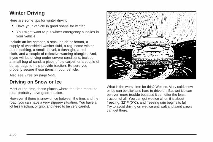
Winter DrivingHere are some tips for winter driving:
• Have your vehicle in good shape for winter.
• You might want to put winter emergency supplies inyour vehicle.
Include an ice scraper, a small brush or broom, asupply of windshield washer fluid, a rag, some winterouter clothing, a small shovel, a flashlight, a redcloth, and a couple of reflective warning triangles. And,if you will be driving under severe conditions, includea small bag of sand, a piece of old carpet, or a couple ofburlap bags to help provide traction. Be sure youproperly secure these items in your vehicle.
Also see Tires on page 5-52.
Driving on Snow or IceMost of the time, those places where the tires meet theroad probably have good traction.
However, if there is snow or ice between the tires and theroad, you can have a very slippery situation. You have alot less traction, or grip, and need to be very careful.
What is the worst time for this? Wet ice. Very cold snowor ice can be slick and hard to drive on. But wet ice canbe even more trouble because it can offer the leasttraction of all. You can get wet ice when it is aboutfreezing, 32°F (0°C), and freezing rain begins to fall.Try to avoid driving on wet ice until salt and sand crewscan get there.
4-22

Whatever the condition — smooth ice, packed, blowing,or loose snow — drive with caution.
Traction control improves your ability to accelerate whendriving on a slippery road. Even if your vehicle hasthe Traction Control System (TCS) or Enhanced TractionSystem (ETS), slow down and adjust your driving tothe road conditions. Under certain conditions, you mightwant to turn the TCS or ETS off, such as when drivingthrough deep snow and loose gravel, to help maintainvehicle motion at lower speeds or if your vehicleever gets stuck in sand, mud, ice, or snow. See TractionControl System (TCS) on page 4-6, Enhanced TractionSystem (ETS) on page 4-9, Electronic StabilityControl (ESC) on page 4-10, and If Your Vehicle isStuck in Sand, Mud, Ice, or Snow on page 4-26.
Accelerate gently. Try not to break the fragile traction.If you accelerate too fast, the drive wheels will spin andpolish the surface under the tires even more.
Unless your vehicle has the Antilock BrakeSystem (ABS), you will want to brake very gently, too.If you have ABS, see Antilock Brake System (ABS)on page 4-5. ABS improves your vehicle’s stability whenyou make a hard stop on a slippery road.
Whether your vehicle has ABS or not, begin stoppingsooner than you would on dry pavement. Without ABS, ifyou feel your vehicle begin to slide, let up on thebrakes a little. Push the brake pedal down steadily toget the most traction you can.
Remember, unless your vehicle has ABS, if you brakeso hard that the wheels stop rolling, you will justslide. Brake so the wheels always keep rolling and youcan still steer.
• Whatever your vehicle’s braking system, allowgreater following distance on any slippery road.
• Watch for slippery spots. The road might be fineuntil you hit a spot that is covered with ice. Onan otherwise clear road, ice patches can appear inshaded areas where the sun cannot reach, suchas around clumps of trees, behind buildings,or under bridges. Sometimes the surface of a curveor an overpass can remain icy when thesurrounding roads are clear. If you see a patch ofice ahead of you, brake before you are on it. Try notto brake while you are actually on the ice, andavoid sudden steering maneuvers.
4-23

If You Are Caught in a BlizzardIf you are stopped by heavy snow, you could be in aserious situation. You should probably stay withyour vehicle unless you know for sure that you are nearhelp and you can hike through the snow. Here aresome things to do to summon help and keep yourselfand your passengers safe:
• Turn on the hazard warning flashers.
• Tie a red cloth to your vehicle to alert police thatyou have been stopped by the snow.
• Put on extra clothing or wrap a blanket around you.If you do not have blankets or extra clothing, makebody insulators from newspapers, burlap bags,rags, floor mats — anything you can wrap aroundyourself or tuck under your clothing to keep warm.
You can run the engine to keep warm, but be careful.
4-24

{CAUTION:
Snow can trap exhaust gases under yourvehicle. This can cause deadly CO (carbonmonoxide) gas to get inside. CO couldovercome you and kill you. You cannot see itor smell it, so you might not know it is in yourvehicle. Clear away snow from around thebase of your vehicle, especially any that isblocking the exhaust pipe. And check aroundagain from time to time to be sure snow doesnot collect there.
Open a window just a little on the side of thevehicle that is away from the wind. This willhelp keep CO out.
Run the engine only as long as you must. This saves fuel.When you run the engine, make it go a little faster thanjust idle. That is, push the accelerator slightly. This usesless fuel for the heat that you get and it keeps the batterycharged. You will need a well-charged battery to restartthe vehicle, and possibly for signaling later on with theheadlamps. Let the heater run for a while.
Then, shut the engine off and close the window almostall the way to preserve the heat. Start the engineagain and repeat this only when you feel reallyuncomfortable from the cold. But do it as little aspossible. Preserve the fuel as long as you can. To helpkeep warm, you can get out of the vehicle and dosome fairly vigorous exercises every half hour or so untilhelp comes.
4-25

If Your Vehicle is Stuck in Sand,Mud, Ice, or SnowSlowly and cautiously spin the wheels to free yourvehicle when stuck in sand, mud, ice, or snow. SeeRocking Your Vehicle to Get It Out on page 4-26.
If your vehicle has a traction system, it can oftenhelp to free a stuck vehicle. Refer to your vehicle’straction system in the Index. If the stuck condition is toosevere for the traction system to free the vehicle, turnthe traction system off and use the rocking method.
{CAUTION:
If you let your vehicle’s tires spin at highspeed, they can explode, and you or otherscould be injured. The vehicle can overheat,causing an engine compartment fire or otherdamage. Spin the wheels as little as possibleand avoid going above 35 mph (55 km/h) asshown on the speedometer.
For information about using tire chains on your vehicle,see Tire Chains on page 5-74.
Rocking Your Vehicle to Get It OutFirst, turn the steering wheel left and right to clear thearea around the front wheels. Turn off any tractionsystem. See Traction Control System (TCS) on page 4-6,Enhanced Traction System (ETS) on page 4-9, andElectronic Stability Control (ESC) on page 4-10. Thenshift back and forth between REVERSE (R) and aforward gear, or with a manual transmission, betweenFIRST (1) or SECOND (2) and REVERSE (R), spinningthe wheels as little as possible. To prevent transmissionwear, wait until the wheels stop spinning before shiftinggears. Release the accelerator pedal while you shift, andpress lightly on the accelerator pedal when thetransmission is in gear. By slowly spinning the wheels inthe forward and reverse directions, you will cause arocking motion that could free your vehicle. If that doesnot get your vehicle out after a few tries, it might need tobe towed out. If your vehicle does need to be towed out,see Towing Your Vehicle on page 4-32.
4-26

Loading Your VehicleIt is very important to know how much weight yourvehicle can carry. Two labels on your vehicleshow how much weight it may properly carry, theTire and Loading Information label and theVehicle Certification label.
{CAUTION:
Do not load your vehicle any heavier thanthe Gross Vehicle Weight Rating (GVWR),or either the maximum front or rear GrossAxle Weight Rating (GAWR). If you do,parts on your vehicle can break, and itcan change the way your vehicle handles.These could cause you to lose controland crash. Also, overloading can shortenthe life of your vehicle.
Tire and Loading Information Label
A vehicle specific Tire and Loading Informationlabel is attached to the vehicle’s center pillar(B-pillar). With the driver’s door open, you will findthe label attached below the door lock post (striker).The tire and loading information label lists thenumber of occupant seating positions (A), and themaximum vehicle capacity weight (B) in kilogramsand pounds. The vehicle capacity weight includesthe weight of all occupants, cargo, and allnonfactory-installed options.
Label Example
4-27
The Tire and Loading Information label also lists thetire size of the original equipment tires (C) and therecommended cold tire inflation pressures (D). Formore information on tires and inflation, see Tires onpage 5-52 and Inflation - Tire Pressure onpage 5-60.
There is also important loading information on theCertification/Tire label. It tells you the GrossVehicle Weight Rating (GVWR) and the GrossAxle Weight Rating (GAWR) for the front and rearaxles. See “Certification/Tire Label” later in thissection.
Steps for Determining Correct Load Limit1. Locate the statement “The combined weight
of occupants and cargo should never exceedXXX kg or XXX lbs” on your vehicle’splacard.
2. Determine the combined weight of the driverand passengers that will be riding in yourvehicle.
3. Subtract the combined weight of the driverand passengers from XXX kg or XXX lbs.
4. The resulting figure equals the availableamount of cargo and luggage load capacity.For example, if the “XXX” amount equals1400 lbs and there will be five 150 lbpassengers in your vehicle, the amount ofavailable cargo and luggage load capacity is650 lbs (1400 − 750 (5 x 150) = 650 lbs).
5. Determine the combined weight of luggageand cargo being loaded on the vehicle. Thatweight may not safely exceed the availablecargo and luggage load capacity calculated inStep 4.
6. If your vehicle will be towing a trailer, the loadfrom your trailer will be transferred to yourvehicle. Consult this manual to determine howthis reduces the available cargo and luggageload capacity for your vehicle.
If your vehicle can tow a trailer, see Towing aTrailer (Manual Transaxle) on page 4-34 or Towinga Trailer (Automatic Transaxle) on page 4-34 forimportant information on towing a trailer, towingsafety rules, and trailering tips.
4-28
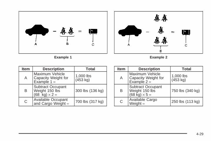
Item Description Total
AMaximum VehicleCapacity Weight forExample 1 =
1,000 lbs(453 kg)
BSubtract OccupantWeight 150 lbs(68 kg) × 2 =
300 lbs (136 kg)
C Available Occupantand Cargo Weight = 700 lbs (317 kg)
Item Description Total
AMaximum VehicleCapacity Weight forExample 2 =
1,000 lbs(453 kg)
BSubtract OccupantWeight 150 lbs(68 kg) × 5 =
750 lbs (340 kg)
C Available CargoWeight = 250 lbs (113 kg)
Example 1 Example 2
4-29

Item Description Total
AMaximum VehicleCapacity Weight forExample 3 =
1,000 lbs(453 kg)
BSubtract OccupantWeight 200 lbs(91 kg) × 5 =
1,000 lbs(453 kg)
C Available CargoWeight = 0 lbs (0 kg)
Refer to your vehicle’s tire and loading informationlabel for specific information about your vehicle’smaximum vehicle capacity weight and seatingpositions. The combined weight of the driver,passengers, and cargo should never exceed yourvehicle’s maximum vehicle capacity weight.
Certification Label
A vehicle specific Certification/Tire label is foundon the rear edge of the driver’s door, or onthe vehicle’s center pillar (B-pillar).
Example 3
4-30

The label shows the size of your original tires andthe inflation pressures needed to obtain thegross weight capacity of your vehicle. This is calledthe Gross Vehicle Weight Rating (GVWR). TheGVWR includes the weight of the vehicle, alloccupants, fuel, and cargo.
The Certification/Tire label also tells you themaximum weights for the front and rear axles,called the Gross Axle Weight Rating (GAWR). Tofind out the actual loads on your front and rearaxles, you need to go to a weigh station and weighyour vehicle. Your dealer can help you with this.Be sure to spread out your load equally onboth sides of the centerline.
Never exceed the GVWR for your vehicle or theGAWR for either the front or rear axle.
{CAUTION:
Do not load your vehicle any heavier thanthe Gross Vehicle Weight Rating (GVWR),or either the maximum front or rear GrossAxle Weight Rating (GAWR). If you do,parts on your vehicle can break, and itcan change the way your vehicle handles.These could cause you to lose controland crash. Also, overloading can shortenthe life of your vehicle.
Notice: Overloading your vehicle may causedamage. Repairs would not be covered by yourwarranty. Do not overload your vehicle.
4-31

If you put things inside your vehicle — likesuitcases, tools, packages, or anything else — theywill go as fast as the vehicle goes. If you have tostop or turn quickly, or if there is a crash, they willkeep going.
{CAUTION:
Things you put inside your vehicle canstrike and injure people in a sudden stopor turn, or in a crash.
• Put things in the cargo area of yourvehicle. Try to spread the weightevenly.
• Never stack heavier things, likesuitcases, inside the vehicle so thatsome of them are above the tops ofthe seats.
• Do not leave an unsecured childrestraint in your vehicle.
• When you carry something inside thevehicle, secure it whenever you can.
• Do not leave a seat folded downunless you need to.
Towing
Towing Your VehicleConsult your dealer/retailer or a professional towingservice if you need to have your disabled vehicle towed.See Roadside Assistance Program on page 7-6.
If you want to tow your vehicle behind another vehiclefor recreational purposes (such as behind a motorhome),see “Recreational Vehicle Towing” following.
Recreational Vehicle TowingRecreational vehicle towing means towing your vehiclebehind another vehicle — such as behind a motorhome.The two most common types of recreational vehicletowing are known as “dinghy towing” (towing your vehiclewith all four wheels on the ground) and “dolly towing”(towing your vehicle with two wheels on the ground andtwo wheels up on a device known as a “dolly”).
4-32

With the proper preparation and equipment, manyvehicles can be towed in these ways. See “DinghyTowing” and “Dolly Towing,” following.
Here are some important things to consider before youdo recreational vehicle towing:
• What is the towing capacity of the towing vehicle?Be sure you read the tow vehicle manufacturer’srecommendations.
• How far will you tow? Some vehicles haverestrictions on how far and how long they can tow.
• Do you have the proper towing equipment?See your dealer/retailer or trailering professional foradditional advice and equipment recommendations.
• Is your vehicle ready to be towed? Just as youwould prepare your vehicle for a long trip, youwill want to make sure your vehicle is prepared tobe towed. See Before Leaving on a Long Tripon page 4-20.
Dinghy TowingYou may dinghy tow your vehicle from the front followingthese steps:
1. Set the parking brake.
2. Turn the ignition key to ACC to unlock the steeringwheel.
3. Shift your transmission to NEUTRAL (N).
4. Release the parking brake.
4-33

To prevent the battery from draining while the vehicle isbeing towed, remove the following fuse from the floorconsole fuse block: 8 (Ignition Switch, PASS-Key® III+).See Floor Console Fuse Block on page 5-120 formore information.
Remember to reinstall the fuse once you have reachedyour destination.
Notice: If you exceed 65 mph (105 km/h) whiletowing your vehicle, it could be damaged. Neverexceed 65 mph (105 km/h) while towing your vehicle.
Notice: Towing your vehicle from the rear coulddamage it. Also, repairs would not be covered bythe warranty. Never have your vehicle towed fromthe rear.
Dolly TowingYour vehicle cannot be dolly towed, but can be dinghytowed. See “Dinghy Towing” earlier in this section.
Notice: Dolly towing your vehicle may causedamage because of reduced ground clearance.Always tow your vehicle using the dinghy towingprocedure listed in this section or put your vehicleon a flatbed truck.
Towing a Trailer (Manual Transaxle)Do not tow a trailer if your vehicle is equipped with amanual transaxle.
Towing a Trailer (AutomaticTransaxle)
{CAUTION:
If you do not use the correct equipment anddrive properly, you can lose control when youpull a trailer. For example, if the trailer is tooheavy, the brakes may not work well — or evenat all. You and your passengers could beseriously injured. You may also damage yourvehicle; the resulting repairs would not becovered by your warranty. Pull a trailer only ifyou have followed all the steps in this section.Ask your dealer/retailer for advice andinformation about towing a trailer with yourvehicle.
4-34

Your vehicle can tow a trailer if it is equipped with anautomatic transmission and the proper trailer towingequipment. If your vehicle is not equipped as statedabove, do not tow a trailer. To identify the traileringcapacity of your vehicle, you should read the informationin “Weight of the Trailer” that appears later in thissection. Trailering is different than just driving yourvehicle by itself. Trailering means changes in handling,acceleration, braking, cooling, durability and fueleconomy. Successful, safe trailering takes correctequipment, and it has to be used properly.
That is the reason for this part. In it are manytime-tested, important trailering tips and safety rules.Many of these are important for your safety and that ofyour passengers. So please read this section carefullybefore you pull a trailer.
Load-pulling components such as the engine,transmission, wheel assemblies and tires are forced towork harder against the drag of the added weight.The engine is required to operate at relatively higherspeeds and under greater loads, generating extra heat.Also, the trailer adds considerably to wind resistance,increasing the pulling requirements.
SS PackageIf your vehicle has the SS package, it is neither designednor intended to tow a trailer.
If You Do Decide To Pull A TrailerIf you do, here are some important points:
• There are many different laws, including speed limitrestrictions, having to do with trailering. Make sureyour rig will be legal, not only where you livebut also where you will be driving. A good sourcefor this information can be state or provincial police.
• Consider using a sway control. You can ask a hitchdealer/retailer about sway controls.
• Do not tow a trailer at all during the first 1,000 miles(1 600 km) your new vehicle is driven. Your engine,axle or other parts could be damaged.
• Then, during the first 500 miles (800 km) that youtow a trailer, do not drive over 50 mph (80 km/h)and do not make starts at full throttle. Thishelps your engine and other parts of your vehiclewear in at the heavier loads.
4-35

• Obey speed limit restrictions when towing a trailer.Do not drive faster than the maximum posted speedfor trailers, or no more than 55 mph (90 km/h), tosave wear on your vehicle’s parts.
• Do not tow when the outside air temperature isabove 100°F (38°C).
• Do not tow more than 1,000 miles (1 600 km)per year.
Three important considerations have to do with weight:
• The weight of the trailer
• The weight of the trailer tongue
• The total weight on your vehicle’s tires
Weight of the TrailerHow heavy can a trailer safely be?
It should never weigh more than 1,000 lbs (450 kg). Buteven that can be too heavy.
It depends on how you plan to use your rig. Forexample, speed, altitude, road grades, outsidetemperature and how much your vehicle is used to pulla trailer are all important. It can also depend on anyspecial equipment that you have on your vehicle,and the amount of tongue weight the vehicle can carry.See “Weight of the Trailer Tongue” later in thissection for more information.
Maximum trailer weight is calculated assuming only thedriver is in the tow vehicle and it has all the requiredtrailering equipment. The weight of additional optionalequipment, passengers and cargo in the tow vehiclemust be subtracted from the maximum trailer weight.
Ask your dealer/retailer for our trailering information oradvice, or write us at our Customer AssistanceOffices. See Customer Assistance Offices on page 7-5for more information.
Weight of the Trailer TongueThe tongue load (A) of any trailer is an important weightto measure because it affects the total or gross weightof your vehicle. The Gross Vehicle Weight (GVW)includes the curb weight of the vehicle, any cargo youmay carry in it, and the people who will be riding inthe vehicle. If you have a lot of options, equipment,passengers, or cargo in your vehicle, it will reduce thetongue weight your vehicle can carry, which will alsoreduce the trailer weight your vehicle can tow. And if youtow a trailer, you must add the tongue load to theGVW because your vehicle will be carrying that weight,too. See Loading Your Vehicle on page 4-27 formore information about your vehicle’s maximum loadcapacity.
4-36

If you are using a weight-carrying hitch, the trailertongue (A) should weigh 10 to 15 percent of the totalloaded trailer weight (B).
After you have loaded your trailer, weigh the trailer andthen the tongue, separately, to see if the weights areproper. If they are not, you may be able to get them rightsimply by moving some items around in the trailer.
Trailering may be limited by the vehicle’s ability to carrytongue weight. Tongue weight cannot cause thevehicle to exceed the GVWR (Gross Vehicle WeightRating) or the RGAWR (Rear Gross Axle WeightRating). The effect of additional weight may reduce yourtrailering capacity more than the total of the additionalweight.
Consider the following example:
A vehicle model base weight is 5,500 lbs (2 495 kg);2,800 lbs (1 270 kg) at the front axle and 2,700 lbs(1 225 kg) at the rear axle. It has a GVWR of 7,200 lbs(3 266 kg), a RGAWR of 4,000 lbs (1 814 kg) and aGCWR (Gross Combination Weight Rating) of14,000 lbs (6 350 kg). The trailer rating should be:
You can expect tongue weight to be at least 10 percentof trailer weight (850 lbs (386 kg)) and because theweight is applied well behind the rear axle, the effect onthe rear axle will be greater than just the weightitself, as much as 1.5 times as much. The weight at therear axle could be 850 lbs (386 kg) X 1.5 = 1,275 lbs(578 kg). Since the rear axle already weighs 2,700 lbs(1 225 kg), adding 1,275 lbs (578 kg) brings thetotal to 3,975 lbs (1 803 kg). This is very close to, butwithin the limit for RGAWR as well. The vehicle is set totrailer up to 8,500 lbs (3 856 kg).
4-37
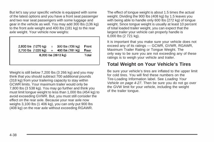
But let’s say your specific vehicle is equipped with someof the latest options and you have a front seat passengerand two rear seat passengers with some luggage andgear in the vehicle as well. You may add 300 lbs (136 kg)to the front axle weight and 400 lbs (181 kg) to the rearaxle weight. Your vehicle now weighs:
Weight is still below 7,200 lbs (3 266 kg) and you maythink that you should subtract 700 additional pounds(318 kg) from your trailering capacity to stay withinGCWR limits. Your maximum trailer would only be7,800 lbs (3 538 kg). You may go further and think youmust limit tongue weight to less than 1,000 lbs (454 kg) toavoid exceeding GVWR. But, you must still consider theeffect on the rear axle. Because your rear axle nowweighs 3,100 lbs (1 406 kg), you can only put 900 lbs(408 kg) on the rear axle without exceeding RGAWR.
The effect of tongue weight is about 1.5 times the actualweight. Dividing the 900 lbs (408 kg) by 1.5 leaves youwith being able to handle only 600 lbs (272 kg) of tongueweight. Since tongue weight is usually at least 10 percentof total loaded trailer weight, you can expect that thelargest trailer your vehicle can properly handle is6,000 lbs (2 721 kg).
It is important that you make sure your vehicle does notexceed any of its ratings — GCWR, GVWR, RGAWR,Maximum Trailer Rating or Tongue Weight. Theonly way to be sure you are not exceeding any of theseratings is to weigh your vehicle and trailer.
Total Weight on Your Vehicle’s TiresBe sure your vehicle’s tires are inflated to the upper limitfor cold tires. You will find these numbers on theTire-Loading Information label. See Loading YourVehicle on page 4-27. Then be sure you do not go overthe GVW limit for your vehicle, including the weightof the trailer tongue.
4-38

HitchesIt is important to have the correct hitch equipment.Crosswinds, large trucks going by and rough roads area few reasons why you will need the right hitch. Hereare some rules to follow:
• The rear bumper on your vehicle is not intended forhitches. Do not attach rental hitches or otherbumper-type hitches to it. Use only a frame-mountedhitch that does not attach to the bumper.
• Will you have to make any holes in the body of yourvehicle when you install a trailer hitch? If you do, thenbe sure to seal the holes later when you remove thehitch. If you do not seal them, deadly carbonmonoxide (CO) from your exhaust can get into yourvehicle. See Engine Exhaust on page 2-37. Dirt andwater can also enter the vehicle.
Safety ChainsYou should always attach chains between your vehicleand your trailer. Cross the safety chains under thetongue of the trailer so that the tongue will not drop tothe road if it becomes separated from the hitch.Instructions about safety chains may be provided by thehitch manufacturer or by the trailer manufacturer.
Follow the manufacturer’s recommendation for attachingsafety chains and do not attach them to the bumper.Always leave just enough slack so you can turnwith your rig. And, never allow safety chains to drag onthe ground.
Trailer BrakesDoes your trailer have its own brakes? Be sure to readand follow the instructions for the trailer brakes soyou will be able to install, adjust and maintain themproperly. Do not try to tap into your vehicle’s brakesystem. If you do, both brake systems will not work well,or at all.
Driving with a TrailerTowing a trailer requires a certain amount of experience.Before setting out for the open road, you will want toget to know your rig. Acquaint yourself with the feel ofhandling and braking with the added weight of the trailer.And always keep in mind that the vehicle you aredriving is now a good deal longer and not nearly asresponsive as your vehicle is by itself.
4-39

Before you start, check all trailer hitch parts andattachments, safety chains, electrical connector, lamps,tires and mirror adjustment. If the trailer has electricbrakes, start your vehicle and trailer moving and thenapply the trailer brake controller by hand to be surethe brakes are working. This lets you check yourelectrical connection at the same time.
During your trip, check occasionally to be sure that theload is secure, and that the lamps and any trailerbrakes are still working.
Following DistanceStay at least twice as far behind the vehicle ahead asyou would when driving your vehicle without a trailer.This can help you avoid situations that requireheavy braking and sudden turns.
PassingYou will need more passing distance up ahead whenyou are towing a trailer. And, because the vehicleis a good deal longer, you will need to go much fartherbeyond the passed vehicle before you can return toyour lane.
Backing UpHold the bottom of the steering wheel with one hand.Then, to move the trailer to the left, just move that handto the left. To move the trailer to the right, move yourhand to the right. Always back up slowly and, if possible,have someone guide you.
Making Turns
Notice: Making very sharp turns while traileringcould cause the trailer to come in contact with thevehicle. Your vehicle could be damaged. Avoidmaking very sharp turns while trailering.
When you are turning with a trailer, make wider turnsthan normal. Do this so your trailer will not strikesoft shoulders, curbs, road signs, trees or other objects.Avoid jerky or sudden maneuvers. Signal well inadvance.
Turn Signals When Towing a TrailerWhen you tow a trailer, your vehicle may need adifferent turn signal flasher and/or extra wiring. Checkwith your dealer/retailer. The arrows on your instrumentpanel will flash whenever you signal a turn or lanechange. Properly hooked up, the trailer lamps will alsoflash, telling other drivers you are about to turn,change lanes or stop.
4-40

When towing a trailer, the arrows on your instrumentpanel will flash for turns even if the bulbs on the trailerare burned out. Thus, you may think drivers behindyou are seeing your signal when they are not. Itis important to check occasionally to be sure the trailerbulbs are still working.
Driving on Grades
Notice: Do not tow on steep continuous gradesexceeding 6 miles (9.6 km). Extended, higherthan normal engine and transmission temperaturesmay result and damage your vehicle. Frequentstops are very important to allow the engine andtransmission to cool.
When towing under severe conditions such as hotambient temperatures or steep grades, your vehicle mayexperience more transmission shifting. A COOLINGMODE ON message may also appear in the DIC. Thisalerts the driver that the shifting mode is in progressand is aiding engine cooling. See DIC Warningsand Messages on page 3-48 DIC Warnings andMessages for more information.
Reduce speed and shift to a lower gear before you startdown a long or steep downgrade. If you do not shiftdown, you might have to use your brakes so much thatthey would get hot and no longer work well.
Pay attention to the engine coolant gage. If the indicatoris in the red area, turn off the air conditioning toreduce engine load. See Engine Overheating onpage 5-26.
Parking on Hills
{CAUTION:
You really should not park your vehicle, with atrailer attached, on a hill. If something goeswrong, your rig could start to move. Peoplecan be injured, and both your vehicle and thetrailer can be damaged.
But if you ever have to park your rig on a hill, here ishow to do it:
1. Apply your regular brakes, but do not shift intoPARK (P) for an automatic transmission, or intogear for a manual transmission. When parkinguphill, turn your wheels away from the curb. Whenparking downhill, turn your wheels into the curb.
2. Have someone place chocks under the trailerwheels.
4-41

3. When the wheel chocks are in place, release theregular brakes until the chocks absorb the load.
4. Reapply the regular brakes. Then apply yourparking brake, and then shift into PARK (P) foran automatic transmission or REVERSE (R) for amanual transmission.
5. Release the regular brakes.
When You Are Ready to Leave AfterParking on a Hill1. Apply your regular brakes and hold the pedal down
while you:
• Start your engine.
• Shift into a gear.
• Release the parking brake.
2. Let up on the brake pedal.
3. Drive slowly until the trailer is clear of the chocks.
4. Stop and have someone pick up and store thechocks.
Maintenance When Trailer TowingYour vehicle will need service more often when you arepulling a trailer. See Scheduled Maintenance onpage 6-4 for more on this. Things that are especiallyimportant in trailer operation are automatic transmissionfluid (do not overfill), engine oil, drive belt, coolingsystem and brake system.
Each of these is covered in this manual, and the Indexwill help you find them quickly. If you are trailering,it is a good idea to review this information before youstart your trip.
Check periodically to see that all hitch nuts and boltsare tight.
Engine Cooling When Trailer TowingYour cooling system may temporarily overheat duringsevere operating conditions. See Engine Overheating onpage 5-26.
4-42
Service ............................................................5-3Accessories and Modifications ..........................5-3California Proposition 65 Warning .....................5-3California Perchlorate Materials Requirements .....5-4Doing Your Own Service Work .........................5-4Adding Equipment to the Outside of Your
Vehicle ......................................................5-4Fuel ................................................................5-5
Gasoline Octane ............................................5-5Gasoline Specifications ....................................5-5California Fuel ...............................................5-6Additives .......................................................5-6Fuels in Foreign Countries ...............................5-7Filling the Tank ..............................................5-7Filling a Portable Fuel Container .....................5-10
Checking Things Under the Hood ....................5-10Hood Release ..............................................5-11Engine Compartment Overview .......................5-12Engine Oil ...................................................5-15Engine Oil Life System ..................................5-19Engine Air Cleaner/Filter ................................5-20Automatic Transmission Fluid .........................5-23Manual Transmission Fluid .............................5-23Hydraulic Clutch ...........................................5-23Engine Coolant .............................................5-24Pressure Cap ...............................................5-26
Engine Overheating .......................................5-26Cooling System ............................................5-28Windshield Washer Fluid ................................5-33Brakes ........................................................5-34Battery ........................................................5-37Jump Starting ...............................................5-38
Headlamp Aiming ...........................................5-43Bulb Replacement ..........................................5-46
Halogen Bulbs ..............................................5-46Headlamps, Front Turn Signal, and Parking
Lamps .....................................................5-46Center High-Mounted Stoplamp (CHMSL) .........5-48Taillamps, Turn Signal, Stoplamps and
Back-up Lamps .........................................5-49License Plate Lamp ......................................5-50Replacement Bulbs .......................................5-50
Windshield Wiper Blade Replacement ..............5-50Tires ..............................................................5-52
Tire Sidewall Labeling ...................................5-53Tire Terminology and Definitions .....................5-57Inflation - Tire Pressure .................................5-60Tire Pressure Monitor System .........................5-61Tire Pressure Monitor Operation .....................5-63Tire Inspection and Rotation ...........................5-66When It Is Time for New Tires .......................5-68
Section 5 Service and Appearance Care
5-1
Buying New Tires .........................................5-69Different Size Tires and Wheels ......................5-71Uniform Tire Quality Grading ..........................5-71Wheel Alignment and Tire Balance ..................5-73Wheel Replacement ......................................5-73Tire Chains ..................................................5-74If a Tire Goes Flat ........................................5-75Tire Sealant and Compressor Kit ....................5-76Changing a Flat Tire .....................................5-86Removing the Spare Tire and Tools ................5-87Removing the Flat Tire and Installing the
Spare Tire (SS Model) ...............................5-90Removing the Flat Tire and Installing the
Spare Tire (All Models Except SS) .............5-101Storing a Flat or Spare Tire and Tools ...........5-106Compact Spare Tire ....................................5-109
Appearance Care ..........................................5-110Interior Cleaning .........................................5-110Fabric/Carpet ..............................................5-111Instrument Panel, Vinyl, and Other Plastic
Surfaces .................................................5-112Care of Safety Belts ....................................5-112Weatherstrips .............................................5-113Washing Your Vehicle ..................................5-113
Cleaning Exterior Lamps/Lenses ....................5-113Finish Care ................................................5-114Windshield and Wiper Blades .......................5-114Aluminum or Chrome-Plated Wheels
and Trim ................................................5-115Tires .........................................................5-116Sheet Metal Damage ...................................5-116Finish Damage ...........................................5-116Underbody Maintenance ...............................5-116Chemical Paint Spotting ...............................5-116Vehicle Care/Appearance Materials ................5-117
Vehicle Identification .....................................5-118Vehicle Identification Number (VIN) ................5-118Service Parts Identification Label ...................5-118
Electrical System ..........................................5-118Add-On Electrical Equipment .........................5-118Headlamp Wiring ........................................5-119Windshield Wiper Fuses ...............................5-119Power Windows and Other Power Options ......5-119Fuses and Circuit Breakers ..........................5-119Floor Console Fuse Block ............................5-120Engine Compartment Fuse Block ...................5-122
Capacities and Specifications ........................5-125
Section 5 Service and Appearance Care
5-2

ServiceFor service and parts needs, visit your dealer/retailer.You will receive genuine GM parts and GM-trained andsupported service people.
Genuine GM parts have one of these marks:
Accessories and ModificationsWhen non-dealer/non-retailer accessories are added toyour vehicle they can affect your vehicle’s performanceand safety, including such things as, airbags, braking,stability, ride and handling, emissions systems,aerodynamics, durability, and electronic systems likeantilock brakes, traction control and stability control.Some of these accessories could even causemalfunction or damage not covered by warranty.
GM Accessories are designed to complement andfunction with other systems on your vehicle. Your GMdealer/retailer can accessorize your vehicle usinggenuine GM Accessories. When you go to your GMdealer/retailer and ask for GM Accessories, you will knowthat GM-trained and supported service technicians willperform the work using genuine GM Accessories.
Also, see Adding Equipment to Your Airbag-EquippedVehicle on page 1-71.
California Proposition 65 WarningMost motor vehicles, including this one, contain and/oremit chemicals known to the State of California tocause cancer and birth defects or other reproductiveharm. Engine exhaust, many parts and systems(including some inside the vehicle), many fluids, andsome component wear by-products contain and/or emitthese chemicals.
5-3
California Perchlorate MaterialsRequirementsCertain types of automotive applications, such as airbaginitiators, seat belt pretensioners, and lithium batteriescontained in remote keyless entry transmitters, maycontain perchlorate materials. Special handlingmay be necessary. For additional information, seewww.dtsc.ca.gov/hazardouswaste/perchlorate.
Doing Your Own Service Work
{CAUTION:
You can be injured and your vehicle could bedamaged if you try to do service work on avehicle without knowing enough about it.
• Be sure you have sufficient knowledge,experience, the proper replacement parts,and tools before you attempt any vehiclemaintenance task.
• Be sure to use the proper nuts, bolts,and other fasteners. English and metricfasteners can be easily confused. If youuse the wrong fasteners, parts can laterbreak or fall off. You could be hurt.
If you want to do some of your own service work, youshould use the proper service manual. It tells you muchmore about how to service your vehicle than thismanual can. To order the proper service manual, seeService Publications Ordering Information on page 7-15.
Your vehicle has an airbag system. Before attemptingto do your own service work, see Servicing YourAirbag-Equipped Vehicle on page 1-70.
You should keep a record with all parts receipts and listthe mileage and the date of any service work youperform. See Maintenance Record on page 6-16.
Adding Equipment to the Outside ofYour VehicleThings you might add to the outside of your vehicle canaffect the airflow around it. This can cause windnoise and can affect fuel economy and windshieldwasher performance. Check with your dealer/retailerbefore adding equipment to the outside of your vehicle.
5-4

FuelUse of the recommended fuel is an important part ofthe proper maintenance of your vehicle. To helpkeep the engine clean and maintain optimum vehicleperformance, we recommend the use of gasolineadvertised as TOP TIER Detergent Gasoline.
The 8th digit of the Vehicle Identification Number (VIN)shows the code letter or number that identifies yourvehicle’s engine. The VIN is at the top left of theinstrument panel. See Vehicle Identification Number(VIN) on page 5-118.
Gasoline OctaneIf your vehicle has the 2.2L L4 engine (VIN Code D),use regular unleaded gasoline with a posted octanerating of 87 or higher. If the octane rating is less than 87,you might notice an audible knocking noise when youdrive, commonly referred to as spark knock. If thisoccurs, use a gasoline rated at 87 octane or higher assoon as possible. If you are using gasoline rated at87 octane or higher and you hear heavy knocking,the engine needs service.
If your vehicle has the 2.0L L4 engine (VIN Code X)or the 2.4L L4 engine (VIN Code P), use premiumunleaded gasoline with a posted octane rating of 91 orhigher. You can also use regular unleaded gasolinerated at 87 octane or higher, but your vehicle’sacceleration could be slightly reduced, and you mightnotice a slight audible knocking noise, commonlyreferred to as spark knock. If the octane is less than 87,you might notice a heavy knocking noise when youdrive. If this occurs, use a gasoline rated at 87 octaneor higher as soon as possible. Otherwise, you coulddamage the engine. If you are using gasoline rated at 87octane or higher and you hear heavy knocking, theengine needs service.
Gasoline SpecificationsAt a minimum, gasoline should meet ASTMspecification D 4814 in the United States orCAN/CGSB-3.5 or 3.511 in Canada. Some gasolinescontain an octane-enhancing additive calledmethylcyclopentadienyl manganese tricarbonyl (MMT).We recommend against the use of gasolinescontaining MMT. See Additives on page 5-6 foradditional information.
5-5

California FuelIf your vehicle is certified to meet California EmissionsStandards, it is designed to operate on fuels thatmeet California specifications. See the underhoodemission control label. If this fuel is not availablein states adopting California emissions standards, yourvehicle will operate satisfactorily on fuels meetingfederal specifications, but emission control systemperformance might be affected. The malfunctionindicator lamp could turn on and your vehicle might faila smog-check test. See Malfunction Indicator Lampon page 3-40. If this occurs, return to your authorizeddealer/retailer for diagnosis. If it is determined thatthe condition is caused by the type of fuel used, repairsmight not be covered by your warranty.
AdditivesTo provide cleaner air, all gasolines in the United Statesare now required to contain additives that help preventengine and fuel system deposits from forming, allowingthe emission control system to work properly. In mostcases, you should not have to add anything to the fuel.However, some gasolines contain only the minimumamount of additive required to meet U.S. EnvironmentalProtection Agency regulations. To help keep fuel injectorsand intake valves clean, or if your vehicle experiencesproblems due to dirty injectors or valves, look for gasoline
that is advertised as TOP TIER Detergent Gasoline.Also, your dealer/retailer has additives that will helpcorrect and prevent most deposit-related problems.
Gasolines containing oxygenates, such as ethers andethanol, and reformulated gasolines might be available inyour area. We recommend that you use these gasolines,if they comply with the specifications described earlier.However, E85 (85% ethanol) and other fuels containingmore than 10% ethanol must not be used in vehicles thatwere not designed for those fuels.
Notice: Your vehicle was not designed for fuel thatcontains methanol. Do not use fuel containingmethanol. It can corrode metal parts in the fuelsystem and also damage plastic and rubber parts.That damage would not be covered under yourwarranty.
Some gasolines that are not reformulated for lowemissions can contain an octane-enhancing additivecalled methylcyclopentadienyl manganese tricarbonyl(MMT); ask the attendant where you buy gasolinewhether the fuel contains MMT. We recommend againstthe use of such gasolines. Fuels containing MMT canreduce the life of spark plugs and the performanceof the emission control system could be affected.The malfunction indicator lamp might turn on. If thisoccurs, return to your dealer/retailer for service.
5-6
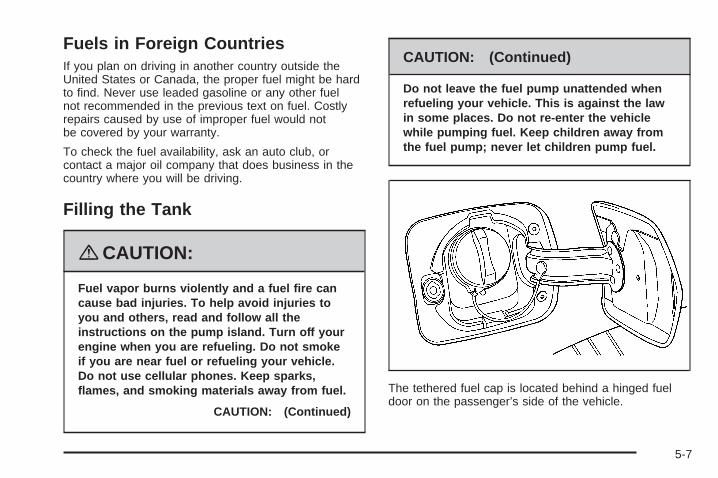
Fuels in Foreign CountriesIf you plan on driving in another country outside theUnited States or Canada, the proper fuel might be hardto find. Never use leaded gasoline or any other fuelnot recommended in the previous text on fuel. Costlyrepairs caused by use of improper fuel would notbe covered by your warranty.
To check the fuel availability, ask an auto club, orcontact a major oil company that does business in thecountry where you will be driving.
Filling the Tank
{CAUTION:
Fuel vapor burns violently and a fuel fire cancause bad injuries. To help avoid injuries toyou and others, read and follow all theinstructions on the pump island. Turn off yourengine when you are refueling. Do not smokeif you are near fuel or refueling your vehicle.Do not use cellular phones. Keep sparks,flames, and smoking materials away from fuel.
CAUTION: (Continued)
CAUTION: (Continued)
Do not leave the fuel pump unattended whenrefueling your vehicle. This is against the lawin some places. Do not re-enter the vehiclewhile pumping fuel. Keep children away fromthe fuel pump; never let children pump fuel.
The tethered fuel cap is located behind a hinged fueldoor on the passenger’s side of the vehicle.
5-7

To open the fuel door, apply pressure in the center ofthe rear edge of the fuel door and it will pop open.
To remove the fuel cap, turn it slowly counterclockwise.The fuel cap has a spring in it; if the cap is releasedtoo soon, it will spring back to the right.
While refueling, hang the tethered fuel cap from thehook on the fuel door.
{CAUTION:
Fuel can spray out on you if you open the fuelcap too quickly. If you spill fuel and thensomething ignites it, you could be badly burned.This spray can happen if your tank is nearly full,and is more likely in hot weather. Open the fuelcap slowly and wait for any hiss noise to stop.Then unscrew the cap all the way.
Be careful not to spill fuel. Do not top off or overfill thetank and wait a few seconds after you have finishedpumping before removing the nozzle. Clean fuel frompainted surfaces as soon as possible. See WashingYour Vehicle on page 5-113.
5-8
When replacing the fuel cap, turn it clockwise untilit clicks. Make sure the cap is fully installed.The diagnostic system can determine if the fuel cap hasbeen left off or improperly installed. This would allowfuel to evaporate into the atmosphere. See MalfunctionIndicator Lamp on page 3-40.
The CHECK GAS CAP message will be displayed onthe Driver Information Center (DIC) if the fuel cap is notproperly installed. See DIC Warnings and Messageson page 3-48 for more information.
To close the fuel door securely, push the door to theclosed position.
{CAUTION:
If a fire starts while you are refueling, do notremove the nozzle. Shut off the flow of fuel byshutting off the pump or by notifying thestation attendant. Leave the area immediately.
Notice: If you need a new fuel cap, be sure to getthe right type. Your dealer/retailer can get onefor you. If you get the wrong type, it may not fitproperly. This may cause your malfunction indicatorlamp to light and may damage your fuel tank andemissions system. See Malfunction Indicator Lampon page 3-40.
5-9

Filling a Portable Fuel Container
{CAUTION:
Never fill a portable fuel container while it is inyour vehicle. Static electricity discharge fromthe container can ignite the fuel vapor. You canbe badly burned and your vehicle damaged ifthis occurs. To help avoid injury to you andothers:
• Dispense fuel only into approvedcontainers.
• Do not fill a container while it is inside avehicle, in a vehicle’s trunk, pickup bed, oron any surface other than the ground.
• Bring the fill nozzle in contact with theinside of the fill opening before operatingthe nozzle. Contact should be maintaineduntil the filling is complete.
• Do not smoke while pumping fuel.• Do not use a cellular phone while
pumping fuel.
Checking Things Underthe Hood
{CAUTION:
An electric fan under the hood can start upand injure you even when the engine is notrunning. Keep hands, clothing, and tools awayfrom any underhood electric fan.
{CAUTION:
Things that burn can get on hot engine partsand start a fire. These include liquids like fuel,oil, coolant, brake fluid, windshield washer andother fluids, and plastic or rubber. You orothers could be burned. Be careful not to dropor spill things that will burn onto a hot engine.
5-10
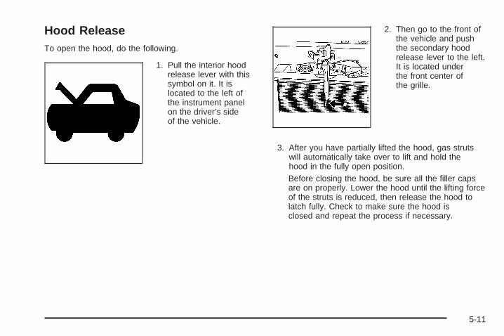
Hood ReleaseTo open the hood, do the following.
1. Pull the interior hoodrelease lever with thissymbol on it. It islocated to the left ofthe instrument panelon the driver’s sideof the vehicle.
2. Then go to the front ofthe vehicle and pushthe secondary hoodrelease lever to the left.It is located underthe front center ofthe grille.
3. After you have partially lifted the hood, gas strutswill automatically take over to lift and hold thehood in the fully open position.Before closing the hood, be sure all the filler capsare on properly. Lower the hood until the lifting forceof the struts is reduced, then release the hood tolatch fully. Check to make sure the hood isclosed and repeat the process if necessary.
5-11

Engine Compartment OverviewWhen you open the hood on the 2.4L engine (2.2L engine similar), here is what you will see:
5-12
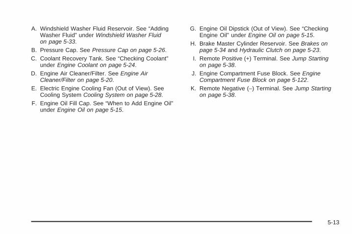
A. Windshield Washer Fluid Reservoir. See “AddingWasher Fluid” under Windshield Washer Fluidon page 5-33.
B. Pressure Cap. See Pressure Cap on page 5-26.C. Coolant Recovery Tank. See “Checking Coolant”
under Engine Coolant on page 5-24.D. Engine Air Cleaner/Filter. See Engine Air
Cleaner/Filter on page 5-20.E. Electric Engine Cooling Fan (Out of View). See
Cooling System Cooling System on page 5-28.F. Engine Oil Fill Cap. See “When to Add Engine Oil”
under Engine Oil on page 5-15.
G. Engine Oil Dipstick (Out of View). See “CheckingEngine Oil” under Engine Oil on page 5-15.
H. Brake Master Cylinder Reservoir. See Brakes onpage 5-34 and Hydraulic Clutch on page 5-23.
I. Remote Positive (+) Terminal. See Jump Startingon page 5-38.
J. Engine Compartment Fuse Block. See EngineCompartment Fuse Block on page 5-122.
K. Remote Negative (−) Terminal. See Jump Startingon page 5-38.
5-13

When you open the hood on the 2.0L L4 engine, this is what you will see:
5-14

A. Pressure Cap. See Pressure Cap on page 5-26.B. Engine Air Cleaner/Filter. See Engine Air
Cleaner/Filter on page 5-20.C. Windshield Washer Fluid Reservoir. See “Adding
Washer Fluid” under Windshield Washer Fluidon page 5-33.
D. Coolant Recovery Tank. See “Checking Coolant”under Engine Coolant on page 5-24.
E. Engine Oil Dipstick. See “Checking Engine Oil”under Engine Oil on page 5-15.
F. Engine Oil Fill Cap. See “When to Add Engine Oil”under Engine Oil on page 5-15.
G. Brake Master Cylinder Reservoir. See “Brake Fluid”under Brakes on page 5-34 and Hydraulic Clutchon page 5-23.
H. Underhood Fuse Block. See Engine CompartmentFuse Block on page 5-122.
I. Remote Negative (−) Terminal. See Jump Startingon page 5-38.
J. Remote Positive (+) Terminal. See Jump Starting onpage 5-38.
Engine OilChecking Engine OilIt is a good idea to check the engine oil every time youget fuel. In order to get an accurate reading, the oilmust be warm and the vehicle must be on level ground.
The engine oil dipstick handle is a yellow loop.See Engine Compartment Overview on page 5-12 forthe location of the engine oil dipstick.1. Turn off the engine and give the oil several minutes
to drain back into the oil pan. If you do not do this,the oil dipstick might not show the actual level.
2. Pull out the dipstick and clean it with a paper towelor cloth, then push it back in all the way. Remove itagain, keeping the tip down, and check the level.
When to Add Engine Oil
If the oil is below the MIN (minimum) mark, addat least one quart/liter of the recommended oil.
5-15
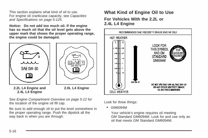
This section explains what kind of oil to use.For engine oil crankcase capacity, see Capacitiesand Specifications on page 5-125.
Notice: Do not add too much oil. If the enginehas so much oil that the oil level gets above theupper mark that shows the proper operating range,the engine could be damaged.
See Engine Compartment Overview on page 5-12 forthe location of the engine oil fill cap.
Be sure to add enough oil to put the level somewhere inthe proper operating range. Push the dipstick all theway back in when you are through.
What Kind of Engine Oil to UseFor Vehicles With the 2.2L or2.4L L4 Engine
Look for three things:
• GM6094M
Your vehicle’s engine requires oil meetingGM Standard GM6094M. Look for and use only anoil that meets GM Standard GM6094M.
2.2L L4 Engine and2.4L L4 Engine
2.0L L4 Engine
5-16

• SAE 5W-30
As shown in the viscosity chart, SAE 5W-30 is bestfor your vehicle.These numbers on an oil container show itsviscosity, or thickness. Do not use other viscosityoils such as SAE 20W-50.
• Oils meeting theserequirements shouldhave the starburstsymbol on the container.This symbol indicatesthat the oil hasbeen certified by theAmerican PetroleumInstitute (API).
Look for this information on the oil container, anduse only those oils that are identified as meetingGM Standard GM6094M and have the starburst symbolon the front of the oil container.
Notice: Use only engine oil identified as meetingGM Standard GM6094M and showing the AmericanPetroleum Institute Certified For Gasoline Enginesstarburst symbol. Failure to use the recommendedoil can result in engine damage not covered byyour warranty.
If you are in an area of extreme cold, where thetemperature falls below −20°F (−29°C), it isrecommended that you use either an SAE 5W-30synthetic oil or an SAE 0W-30 oil. Both provide easiercold starting and better protection for the engine atextremely low temperatures.
5-17

For Vehicles with the 2.0L L4 Engine Only
Look for three things:
• GM4718M
Your vehicle’s engine requires a special oil meetingGM Standard GM4718M, such as Mobil 1® orequivalent. Oils meeting this standard maybe identified as synthetic. However, not all syntheticoils will meet this GM standard. Look for and useonly an oil that meets GM Standard GM4718M.
Notice: If you use oils that do not have theGM4718M Standard designation, you can causeengine damage not covered by your warranty.
• SAE 5W-30
As shown in the viscosity chart, SAE 5W-30 is bestfor your vehicle.These numbers on an oil container show itsviscosity, or thickness. Do not use other viscosityoils such as SAE 20W-50.
• Oils meeting theserequirements shouldhave the starburstsymbol on the container.This symbol indicatesthat the oil hasbeen certified by theAmerican PetroleumInstitute (API).
Look for this on the oil container, and use only thoseoils that are identified as meeting GM StandardGM4718M and have the starburst symbol on the frontof the oil container.
5-18

Your vehicle’s engine is filled at the factory with asynthetic oil which meets all requirements for yourvehicle.
Substitute Engine Oil: When adding oil to maintainengine oil level, oil meeting GM Standard GM4718Mmay not be available. You can add substitute oildesignated SAE 5W-30 with the starburst symbol at alltemperatures. Substitute oil not meeting GM StandardGM4718M should not be used for an oil change.
Engine Oil AdditivesDo not add anything to the oil. The recommended oilswith the starburst symbol that meet GM standards are allyou need for good performance and engine protection.
Engine Oil Life System
When to Change Engine OilYour vehicle has the Engine Oil Life System, a computersystem that lets you know when to change the engineoil and filter. This is based on engine revolutionsand engine temperature, and not on mileage.
Based on driving conditions, the mileage at whichan oil change will be indicated can vary considerably.For the oil life system to work properly, you mustreset the system every time the oil is changed.
When the system has calculated that oil life has beendiminished, it will indicate that an oil change isnecessary. A CHANGE OIL SOON message will comeon. See DIC Warnings and Messages on page 3-48.Change the oil as soon as possible within the next600 miles (1 000 km). It is possible that, if you aredriving under the best conditions, the oil life systemmight not indicate that an oil change is necessaryfor over a year. However, the engine oil and filter mustbe changed at least once a year and at this time thesystem must be reset. Your dealer/retailer has trainedservice people who will perform this work using genuineparts and reset the system. It is also important tocheck the oil regularly and keep it at the proper level.
If the system is ever reset accidentally, you mustchange the oil at 3,000 miles (5 000 km) since the lastoil change. Remember to reset the oil life systemwhenever the oil is changed.
5-19

How to Reset the Engine Oil Life SystemThe Engine Oil Life System calculates when to changeyour engine oil and filter based on vehicle use.Whenever the oil is changed, reset the system so it cancalculate when the next oil change is required. If asituation occurs where you change the oil priorto a CHANGE OIL SOON message being turned on,reset the system.
After changing the engine oil, the system must be reset:
1. Turn the ignition to ON/RUN, with the engine off.
2. Press the information and reset buttons on theDriver Information Center (DIC) at the sametime to enter the personalization menu. See DICVehicle Personalization on page 3-54.
3. Press the information button to scroll through theavailable personalization menu modes until theDIC display shows OIL-LIFE RESET.
4. Press and hold the reset button until the DICdisplay shows ACKNOWLEDGED. This will tell youthe system has been reset.
5. Turn the key to LOCK/OFF.
If the CHANGE OIL SOON message comes back onwhen you start your vehicle, the engine oil life systemhas not reset. Repeat the reset procedure.
What to Do with Used OilUsed engine oil contains certain elements that can beunhealthy for your skin and could even cause cancer.Do not let used oil stay on your skin for very long. Cleanyour skin and nails with soap and water, or a goodhand cleaner. Wash or properly dispose of clothing orrags containing used engine oil. See the manufacturer’swarnings about the use and disposal of oil products.
Used oil can be a threat to the environment. If youchange your own oil, be sure to drain all the oil from thefilter before disposal. Never dispose of oil by putting itin the trash, pouring it on the ground, into sewers, or intostreams or bodies of water. Instead, recycle it bytaking it to a place that collects used oil. If you have aproblem properly disposing of used oil, ask yourdealer/retailer, a service station, or a local recyclingcenter for help.
Engine Air Cleaner/Filter
When to Inspect the Engine AirCleaner/FilterInspect the air cleaner/filter at the Maintenance IIintervals and replace it at the first oil change after each50,000 mile (80 000 km) interval. See ScheduledMaintenance on page 6-4 for more information.
5-20

If you are driving in dusty/dirty conditions, inspect thefilter at each engine oil change. For vehicles withthe 2.0L engine, inspect at each oil change. Replacefilter if it appears dusty or dirty.
How to Inspect the Engine AirCleaner/Filter (2.2L or 2.4L Engine)
See Engine Compartment Overview on page 5-12 forthe location of the engine air cleaner/filter.
To inspect the air cleaner/filter remove the filter fromthe vehicle and lightly shake the filter to releaseloose dust and dirt. If the filter remains caked with dirt,a new filter is required. Never use compressed airto clean the filter.
Because this operation can be a little difficult, you maychoose to have this done at the dealer/retailer servicedepartment.
To inspect or replace the filter, do the following:
1. Disconnect the MAF sensor, PCV hose, andboth ducts.
2. Pull the entire system from the top of the engine.
3. Turn the system over and place it on a soft,non-abrasive surface.
4. Remove the screws that hold the housing andcover together and lift off the housing.
5. Inspect or replace the engine air cleaner/filter.
6. Reverse the steps to reinstall the system. Be sureto reinstall the housing tightly.
5-21

How to Inspect the EngineAir Cleaner/Filter (2.0L Engine Only)
See Engine Compartment Overview on page 5-12 forthe location of the engine air cleaner/filter.
To inspect the air cleaner/filter remove the filter from thevehicle and lightly shake the filter to release loosedust and dirt. If the filter remains caked with dirt, a newfilter is required. Never use compressed air to cleanthe filter.
Because this operation can be a little difficult, you maychoose to have this done at the dealer/retailer servicedepartment.
To inspect or replace the filter, do the following:
1. Remove the screws that hold the housing andcover together and lift off the cover.
2. Inspect or replace the engine air cleaner/filter.
3. Reverse the steps to reinstall the system. Be sureto reinstall the housing tightly.
{CAUTION:
Operating the engine with the air cleaner/filteroff can cause you or others to be burned.The air cleaner not only cleans the air; it helpsto stop flames if the engine backfires. If it isnot there and the engine backfires, you couldbe burned. Do not drive with it off, and becareful working on the engine with the aircleaner/filter off.
Notice: If the air cleaner/filter is off, a backfirecan cause a damaging engine fire. And, dirt caneasily get into your engine, which will damage it.Always have the air cleaner/filter in place when youare driving.
5-22

Automatic Transmission FluidIt is not necessary to check the transmission fluidlevel. A transmission fluid leak is the only reason forfluid loss. If a leak occurs, take your vehicle to adealer/retailer and have it repaired as soon as possible.
Change the fluid and filter at the intervals listed inthe Maintenance Schedule. See Scheduled Maintenanceon page 6-4. Be sure to use the transmission fluidlisted in Recommended Fluids and Lubricants onpage 6-12.
Notice: Use of the incorrect automatic transmissionfluid may damage your vehicle, and the damagesmay not be covered by your warranty. Alwaysuse the automatic transmission fluid listed inRecommended Fluids and Lubricants on page 6-12.
Manual Transmission FluidIt is not necessary to check the manual transmissionfluid level. A transmission fluid leak is the only reasonfor fluid loss. If a leak occurs, take the vehicle to adealer/retailer for service. Have it repaired as soon aspossible. You may also have your fluid level checked byyour dealer/retailer when you have your oil changed.See Recommended Fluids and Lubricants on page 6-12for the proper fluid to use.
Hydraulic ClutchThe hydraulic clutch linkage in your vehicle isself-adjusting. This system does not have its ownreservoir. It receives fluid from the brake mastercylinder reservoir.
See Brakes on page 5-34 for more information.
5-23
Engine CoolantThe cooling system in your vehicle is filled withDEX-COOL® engine coolant. This coolant is designedto remain in your vehicle for five years or 150,000 miles(240 000 km), whichever occurs first, if you add onlyDEX-COOL® extended life coolant.
The following explains your cooling system and how toadd coolant when it is low. If you have a problemwith engine overheating, see Engine Overheating onpage 5-26.
A 50/50 mixture of clean, drinkable water andDEX-COOL® coolant will:• Give freezing protection down to −34°F (−37°C).
• Give boiling protection up to 265°F (129°C).
• Protect against rust and corrosion.
• Help keep the proper engine temperature.
• Let the warning lights and gages work as theyshould.
Notice: Using coolant other than DEX-COOL® maycause premature engine, heater core, or radiatorcorrosion. In addition, the engine coolant mayrequire changing sooner, at the first maintenanceservice after each 30,000 miles (50 000 km) or24 months, whichever occurs first. Any repairswould not be covered by your warranty. Always useDEX-COOL® (silicate-free) coolant in your vehicle.
What to UseUse a mixture of one-half clean, drinkable water andone-half DEX-COOL® coolant which will not damagealuminum parts. If you use this coolant mixture, you donot need to add anything else.
{CAUTION:
Adding only plain water to your coolingsystem can be dangerous. Plain water, orsome other liquid such as alcohol, can boilbefore the proper coolant mixture will. Yourvehicle’s coolant warning system is set for theproper coolant mixture. With plain water or thewrong mixture, your engine could get too hotbut you would not get the overheat warning.Your engine could catch fire and you or otherscould be burned. Use a 50/50 mixture of clean,drinkable water and DEX-COOL® coolant.
Notice: If you use an improper coolant mixture,your engine could overheat and be badly damaged.The repair cost would not be covered by yourwarranty. Too much water in the mixture can freezeand crack the engine, radiator, heater core, andother parts.
5-24

If you have to add coolant more than four times a year,have your dealer/retailer check your cooling system.
Notice: If you use extra inhibitors and/or additivesin your vehicle’s cooling system, you coulddamage your vehicle. Use only the proper mixtureof the engine coolant listed in this manual forthe cooling system. See Recommended Fluids andLubricants on page 6-12 for more information.
Checking CoolantThe coolant recovery tankcap has this symbol on it.The tank is located inthe engine compartmenttoward the front of theengine on the passenger’sside of the vehicle.
See Engine Compartment Overview on page 5-12 formore information on location.
The vehicle must be on a level surface when checkingthe coolant level.
When the engine is cold, the coolant level should be atthe COLD FILL (A) line or a little higher. The COLDFILL line is near the bottom of the tank and sticks outfrom the rear of the tank.
5-25

Adding CoolantIf more coolant is needed, add the proper DEX-COOL®
coolant mixture at the coolant recovery tank, butonly when the engine is cool.
If the coolant recovery tank is completely empty, aspecial fill procedure is necessary. See Cooling Systemon page 5-28 for more information.
{CAUTION:
Turning the radiator pressure cap when theengine and radiator are hot can allow steamand scalding liquids to blow out and burn youbadly. With the coolant recovery tank, you willalmost never have to add coolant at theradiator. Never turn the radiator pressurecap — even a little — when the engine andradiator are hot.
{CAUTION:
You can be burned if you spill coolant on hotengine parts. Coolant contains ethylene glycol,and it will burn if the engine parts are hotenough. Do not spill coolant on a hot engine.
Pressure CapNotice: If the pressure cap is not tightly installed,coolant loss and possible engine damage may occur.Be sure the cap is properly and tightly secured.
See Engine Compartment Overview on page 5-12for more information on location.
Engine OverheatingYou will find a coolant temperature warning light and acoolant temperature gage on your vehicle’s instrumentpanel. See Engine Coolant Temperature WarningLight on page 3-38 and Engine Coolant TemperatureGage on page 3-39 for more information.
5-26

If Steam Is Coming From Your Engine
{CAUTION:
Steam from an overheated engine can burnyou badly, even if you just open the hood.Stay away from the engine if you see or hearsteam coming from it. Just turn it off and geteveryone away from the vehicle until it coolsdown. Wait until there is no sign of steam orcoolant before you open the hood.
If you keep driving when your engine isoverheated, the liquids in it can catch fire.You or others could be badly burned. Stopyour engine if it overheats, and get out of thevehicle until the engine is cool.
Notice: If your engine catches fire because youkeep driving with no coolant, your vehicle canbe badly damaged. The costly repairs would not becovered by your warranty.
If No Steam Is Coming FromYour EngineAn engine coolant temperature warning can indicate aserious problem. See Engine Coolant TemperatureWarning Light on page 3-38.
If you get an engine coolant temperature warning, butsee or hear no steam, the problem may not be tooserious. Sometimes the engine can get a little too hotwhen you:• Climb a long hill on a hot day.
• Stop after high-speed driving.
• Idle for long periods in traffic.
• Tow a trailer.
If you get the engine coolant temperature warning withno sign of steam, try this for a minute or so:
1. If you have an air conditioner and it is on, turn it off.
2. In heavy traffic, let the engine idle in NEUTRAL (N)while stopped. If it is safe to do so, pull off the road,shift to PARK (P) or NEUTRAL (N) and let theengine idle.
3. Turn on your heater to full hot at the highest fanspeed and open the windows as necessary.
5-27

If you no longer have the overheat warning, you candrive. Just to be safe, drive slower for about 10 minutes.If the warning does not come back on, you can drivenormally.
If the warning continues and you have not stopped, pullover, stop, and park your vehicle right away.
If there is still no sign of steam, you can idle the enginefor three minutes while you are parked. If you stillhave the warning, turn off the engine and get everyoneout of the vehicle until it cools down.
You may decide not to lift the hood but to get servicehelp right away.
Cooling SystemWhen you decide it is safe to lift the hood, here is whatyou will see:
A. Pressure CapB. Coolant Recovery TankC. Electric Engine Cooling Fan
5-28

{CAUTION:
An electric engine cooling fan under the hoodcan start up even when the engine is notrunning and can injure you. Keep hands,clothing, and tools away from any underhoodelectric fan.
If the coolant inside the coolant recovery tank isboiling, do not do anything else until it cools down.The vehicle should be parked on a level surface.
When the engine is cold, the coolant level should be ator above the COLD FILL line. If it is not, you mayhave a leak at the pressure cap or in the radiator hoses,heater hoses, radiator, water pump, or somewhere inthe cooling system.
{CAUTION:
Heater and radiator hoses, and other engineparts, can be very hot. Do not touch them.If you do, you can be burned.
Do not run the engine if there is a leak. If yourun the engine, it could lose all coolant.That could cause an engine fire, and you couldbe burned. Get any leak fixed before you drivethe vehicle.
If there seems to be no leak, with the engine on, checkto see if the electric engine cooling fan is running.If the engine is overheating, the fan should be running.If it is not, than the vehicle needs service.
Notice: Engine damage from running the enginewithout coolant is not covered by the warranty.
Notice: Using coolant other than DEX-COOL® maycause premature engine, heater core, or radiatorcorrosion. In addition, the engine coolant couldrequire changing sooner, at 30,000 miles (50 000 km)or 24 months, whichever occurs first. Any repairswould not be covered by the warranty. Always useDEX-COOL® (silicate-free) coolant in the vehicle.
5-29

How to Add Coolant to theCooling System
Notice: The engine has a specific cooling systemdrain and fill procedure. Failure to follow thisprocedure could cause the engine to overheat andbe severely damaged. If the engine’s cooling systemneeds to be drained and re-filled, please see thedealer/retailer.
If no problem is found, but the coolant level in thecoolant recovery tank is below the COLD FILL line,add a 50/50 mixture of clean, drinkable water andDEX-COOL® engine coolant at the coolant recoverytank. See Engine Coolant on page 5-24 for moreinformation.
If no coolant is visible in the coolant recovery tank, addcoolant at the pressure cap as follows:
{CAUTION:
Steam and scalding liquids from a hot coolingsystem can blow out and burn you badly.They are under pressure, and if you turn thepressure cap — even a little — they can comeout at high speed. Never turn the cap when thecooling system, including the pressure cap, ishot. Wait for the cooling system and pressurecap to cool if you ever have to turn thepressure cap.
5-30

{CAUTION:
Adding only plain water to the cooling systemcan be dangerous. Plain water, or some otherliquid such as alcohol, can boil before theproper coolant mixture will. The vehicle’scoolant warning system is set for the propercoolant mixture. With plain water or the wrongmixture, the engine could get too hot but youwould not get the overheat warning. The enginecould catch fire and you or others could beburned. Use a 50/50 mixture of clean, drinkablewater and DEX-COOL® coolant.
Notice: In cold weather, water can freeze and crackthe engine, radiator, heater core and other parts.Use the recommended coolant and the propercoolant mixture.
{CAUTION:
You can be burned if you spill coolant on hotengine parts. Coolant contains ethylene glycoland it will burn if the engine parts are hotenough. Do not spill coolant on a hot engine.
1. Remove the pressurecap when the coolingsystem, includingthe pressure cap andupper radiator hose,is no longer hot.
Turn the pressure cap slowly counterclockwise.If you hear a hiss, wait for that to stop. A hissmeans there is still some pressure left to be vented.
2. Then keep turning the pressure cap and remove it.
5-31

3. Add the proper DEX-COOL® coolant mixture tothe coolant fill port, up to the base of the port.See Engine Coolant on page 5-24 for moreinformation about the proper coolant mixture.
4. Rinse or wipe any spilled coolant from the engineand the compartment.
5. Then fill the coolant recovery tank to the COLDFILL (A) line.
6. Put the cap back on the coolant recovery tank, butleave the pressure cap off.
7. Start the engine and let it run until you can feel theupper radiator hose getting hot. Watch out for theengine cooling fan.
8. By this time, the coolant level inside the radiatorfiller port may be lower. If the level is lower, addmore of the proper DEX-COOL® coolant mixturethrough the fill port until the level reaches the baseof the fill port.
9. Then replace the pressure cap. At any time duringthis procedure, if coolant begins to flow out of thefill port, reinstall the pressure cap. Be sure thepressure cap is hand-tight and fully seated.
10. When the engine has cooled, check the coolant inthe coolant recovery tank. The level in the coolantrecovery tank should be at the COLD FILL linewhen the engine is cold.
5-32

Windshield Washer Fluid
What to UseWhen you need windshield washer fluid, be sure to readthe manufacturer’s instructions before use. If you willbe operating your vehicle in an area where thetemperature may fall below freezing, use a fluid that hassufficient protection against freezing.
Adding Washer Fluid
Open the cap with thewasher symbol on it.Add washer fluid until thetank is full. See EngineCompartment Overview onpage 5-12 for reservoirlocation.
Notice:
• When using concentrated washer fluid, followthe manufacturer’s instructions for addingwater.
• Do not mix water with ready-to-use washer fluid.Water can cause the solution to freeze anddamage your washer fluid tank and other partsof the washer system. Also, water does notclean as well as washer fluid.
• Fill the washer fluid tank only three-quarters fullwhen it is very cold. This allows for fluidexpansion if freezing occurs, which coulddamage the tank if it is completely full.
• Do not use engine coolant (antifreeze) in yourwindshield washer. It can damage the vehicle’swindshield washer system and paint.
5-33

Brakes
Brake FluidThe brake mastercylinder and, on manualtransmission vehicles,the clutch hydraulic systemuse the same reservoir.The reservoir is filled withDOT-3 brake fluid.
There are only two reasons why the brake fluid levelin the reservoir might go down. The first is that the brakefluid goes down to an acceptable level during normalbrake lining wear. When new linings are put in, the fluidlevel goes back up. The other reason is that fluid isleaking out of the brake or clutch hydraulic system.If it is, you should have the brake or clutch hydraulicsystem fixed, since a leak means that sooner orlater your brakes or clutch will not work well.
It is not a good idea to top off the brake fluid. Addingbrake fluid will not correct a leak. If fluid is added whenthe linings are worn, there will be too much fluidwhen new brake linings are installed. Add or removebrake fluid, as necessary, only when work is done onthe brake or clutch hydraulic system.
{CAUTION:
If your vehicle has too much brake fluid, it canspill on the engine. The fluid will burn if theengine is hot enough. You or others could beburned, and your vehicle could be damaged.Add brake fluid only when work is done on thebrake hydraulic system.
When the brake fluid falls to a low level, the brakewarning light will come on. See Brake System WarningLight on page 3-35.
5-34

What to AddWhen you do need brake fluid, use only DOT-3 brakefluid. Use new brake fluid from a sealed containeronly. See Recommended Fluids and Lubricants onpage 6-12.
Always clean the brake fluid reservoir cap and the areaaround the cap before removing it. This helps keepdirt from entering the reservoir.
{CAUTION:
With the wrong kind of fluid in the brake orclutch hydraulic system, the brakes or clutchmight not work well. This could cause a crash.Always use the proper brake fluid.
Notice:
• Using the wrong fluid can badly damage brakeor clutch hydraulic system parts. For example,just a few drops of mineral-based oil, suchas engine oil, in the brake or clutch hydraulicsystem can damage brake or clutch hydraulicsystem parts so badly that they will haveto be replaced. Do not let someone put in thewrong kind of fluid.
• If you spill brake fluid on your vehicle’s paintedsurfaces, the paint finish can be damaged.Be careful not to spill brake fluid on yourvehicle. If you do, wash it off immediately.See Washing Your Vehicle on page 5-113.
5-35

Brake WearYour vehicle has front disc brakes and could have reardrum brakes or rear disc brakes.
Disc brake pads have built-in wear indicators that makea high-pitched warning sound when the brake padsare worn and new pads are needed. The soundcan come and go or be heard all the time your vehicleis moving, except when you are pushing on thebrake pedal firmly.
{CAUTION:
The brake wear warning sound means that soonthe brakes will not work well. That could lead toan accident. When you hear the brake wearwarning sound, have your vehicle serviced.
Notice: Continuing to drive with worn-out brakepads could result in costly brake repair.
Some driving conditions or climates can cause a brakesqueal when the brakes are first applied or lightlyapplied. This does not mean something is wrong withthe brakes.
Properly torqued wheel nuts are necessary to helpprevent brake pulsation. When tires are rotated, inspectbrake pads for wear and evenly tighten wheel nuts inthe proper sequence to torque specifications inCapacities and Specifications on page 5-125.
If your vehicle has rear drum brakes, they do not havewear indicators, but if you ever hear a rear brakerubbing noise, have the rear brake linings inspectedimmediately. Rear brake drums should be removed andinspected each time the tires are removed for rotationor changing. When you have the front brake padsreplaced, have the rear brakes inspected, too.
Brake linings should always be replaced as completeaxle sets.
Brake Pedal TravelSee your dealer/retailer if the brake pedal does notreturn to normal height, or if there is a rapid increase inpedal travel. This could be a sign that brake servicemight be required.
Brake AdjustmentEvery time you apply the brakes, with or without thevehicle moving, the brakes adjust for wear.
5-36

Replacing Brake System PartsThe braking system on a vehicle is complex. Its manyparts have to be of top quality and work well together ifthe vehicle is to have really good braking. Your vehiclewas designed and tested with top-quality brake parts.When you replace parts of the braking system — forexample, when the brake linings wear down and youneed new ones put in — be sure you get new approvedreplacement parts. If you do not, the brakes might notwork properly. For example, if someone puts in brakelinings that are wrong for your vehicle, the balancebetween the front and rear brakes can change — for theworse. The braking performance you have come toexpect can change in many other ways if someone putsin the wrong replacement brake parts.
BatteryYour vehicle has a maintenance free battery. When itis time for a new battery, see your dealer/retailer forone that has the replacement number shown onthe original battery’s label.
Your vehicle’s battery is located in the cargo area.You do not need to access the battery to jump startyour vehicle. See Jump Starting on page 5-38.
Warning: Battery posts, terminals, and relatedaccessories contain lead and lead compounds,chemicals known to the State of California to causecancer and reproductive harm. Wash hands afterhandling.
Vehicle Storage
{CAUTION:
Batteries have acid that can burn you and gasthat can explode. You can be badly hurt if youare not careful. See Jump Starting on page 5-38for tips on working around a battery withoutgetting hurt.
Infrequent Usage: If you drive your vehicle infrequently,remove the black, negative (−) cable from the battery.This will help keep the battery from running down.
Extended Storage: For extended storage of your vehicle,remove the black, negative (−) cable from the batteryor use a battery trickle charger. This will help maintainthe charge of the battery over an extended periodof time.
5-37

Jump StartingIf your vehicle’s battery has run down, you may want touse another vehicle and some jumper cables to startyour vehicle. Be sure to use the following steps todo it safely.
{CAUTION:
Batteries can hurt you. They can be dangerousbecause:
• They contain acid that can burn you.• They contain gas that can explode
or ignite.• They contain enough electricity to
burn you.
If you do not follow these steps exactly, someor all of these things can hurt you.
Notice: Ignoring these steps could result in costlydamage to your vehicle that would not be coveredby your warranty.
Trying to start your vehicle by pushing or pulling itwill not work, and it could damage your vehicle.
1. Check the other vehicle. It must have a 12-voltbattery with a negative ground system.
Notice: If the other vehicle’s system is not a 12-voltsystem with a negative ground, both vehicles canbe damaged. Only use vehicles with 12-volt systemswith negative grounds to jump start your vehicle.
2. Get the vehicles close enough so the jumper cablescan reach, but be sure the vehicles are not touchingeach other. If they are, it could cause a groundconnection you do not want. You would not be ableto start your vehicle, and the bad groundingcould damage the electrical systems.To avoid the possibility of the vehicles rolling, setthe parking brake firmly on both vehicles involvedin the jump start procedure. Put an automatictransaxle in PARK (P) or a manual transaxle inNEUTRAL before setting the parking brake.
5-38

Notice: If you leave your radio or other accessorieson during the jump starting procedure, they couldbe damaged. The repairs would not be coveredby your warranty. Always turn off your radio andother accessories when jump starting your vehicle.
3. Turn off the ignition on both vehicles. Unplugunnecessary accessories plugged into the cigarettelighter or the accessory power outlet. Turn offthe radio and all lamps that are not needed.This will avoid sparks and help save both batteries.And it could save the radio!
4. Open the hood on the other vehicle and locate thepositive (+) and negative (−) terminal locations onthat vehicle.You will not see the battery of your vehicle underthe hood. It is located in the rear cargo area.You will not need to access your battery for jumpstarting. Your vehicle has a remote positive (+) anda remote negative (−) jump starting terminal.
The remote positiveterminal is located undera red tethered cap onthe engine compartmentfuse block. Removethe cap to access theterminal.
Do not remove fuse block cover to jump startthe vehicle.
The remote negative (−)ground terminal, markedGND (−), is located atthe front of the enginecompartment on thedriver’s side of the vehicle.
5-39
{CAUTION:
An electric fan can start up even when theengine is not running and can injure you.Keep hands, clothing and tools away from anyunderhood electric fan.
{CAUTION:
Using a match near a battery can cause batterygas to explode. People have been hurt doingthis, and some have been blinded. Use aflashlight if you need more light.
CAUTION: (Continued)
CAUTION: (Continued)
Be sure the battery has enough water. You donot need to add water to the battery installedin your new vehicle. But if a battery has fillercaps, be sure the right amount of fluid is there.If it is low, add water to take care of that first.If you don’t, explosive gas could be present.
Battery fluid contains acid that can burn you.Do not get it on you. If you accidentally get itin your eyes or on your skin, flush the placewith water and get medical help immediately.
{CAUTION:
Fans or other moving engine parts can injureyou badly. Keep your hands away from movingparts once the engine is running.
5-40

5. Check that the jumper cables do not have loose ormissing insulation. If they do, you could get ashock. The vehicles could be damaged too.Before you connect the cables, here are somebasic things you should know. Positive (+) will go topositive (+) or to a remote positive (+) terminal ifthe vehicle has one. Negative (−) will go to a heavy,unpainted metal engine part or to a remotenegative (−) terminal if the vehicle has one.Do not connect positive (+) to negative (−) or youwill get a short that would damage the batteryand maybe other parts too. And do not connect thenegative (−) cable to the negative (−) terminal onthe dead battery because this can cause sparks.
6. Connect the red positive (+) cable to the positive (+)terminal location on the vehicle with the deadbattery. Use a remote positive (+) terminal if thevehicle has one.
7. Do not let the other end touch metal. Connect it tothe positive (+) terminal of the good battery. Use aremote positive (+) terminal if the vehicle has one.
8. Now connect the black negative (−) cable to thenegative (−) terminal of the good battery. Use aremote negative (−) terminal if the vehicle has one.Do not let the other end touch anything until thenext step. The other end of the negative (−) cabledoes not go to the dead battery. It goes to aheavy, unpainted metal engine part or to a remotenegative (−) terminal on the vehicle with thedead battery.
9. Connect the other end of the negative (−) cable tothe negative (−) terminal location on the vehicle withthe dead battery. Your vehicle has a remotenegative (−) ground terminal marked GND (−).
10. Now start the vehicle with the good battery and runthe engine for a while.
11. Try to start the vehicle that had the dead battery.If it will not start after a few tries, it probably needsservice.
5-41
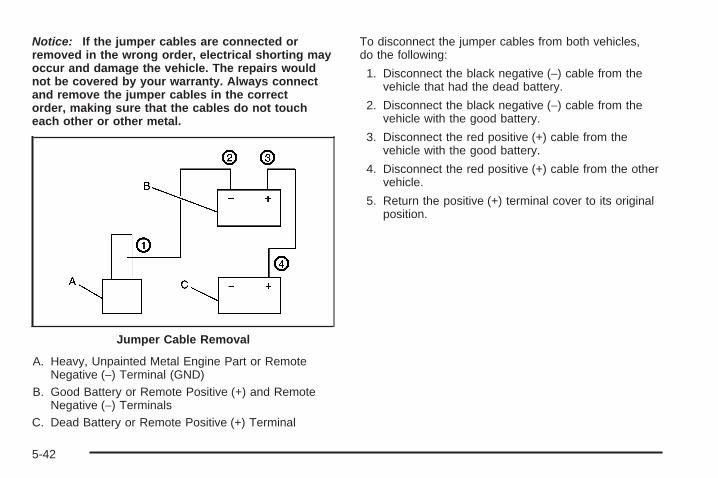
Notice: If the jumper cables are connected orremoved in the wrong order, electrical shorting mayoccur and damage the vehicle. The repairs wouldnot be covered by your warranty. Always connectand remove the jumper cables in the correctorder, making sure that the cables do not toucheach other or other metal.
A. Heavy, Unpainted Metal Engine Part or RemoteNegative (−) Terminal (GND)
B. Good Battery or Remote Positive (+) and RemoteNegative (−) Terminals
C. Dead Battery or Remote Positive (+) Terminal
To disconnect the jumper cables from both vehicles,do the following:
1. Disconnect the black negative (−) cable from thevehicle that had the dead battery.
2. Disconnect the black negative (−) cable from thevehicle with the good battery.
3. Disconnect the red positive (+) cable from thevehicle with the good battery.
4. Disconnect the red positive (+) cable from the othervehicle.
5. Return the positive (+) terminal cover to its originalposition.
Jumper Cable Removal
5-42

Headlamp AimingThe vehicle has a visual optical headlamp aimingsystem. The aim has been preset at the factory andshould need no further adjustment.
However, if the vehicle is damaged in a crash, theheadlamp aim may be affected and adjustment may benecessary.
If oncoming vehicles flash their high beams at you, thismay also mean the vertical aim needs to be adjusted.
It is recommended that the vehicle is taken to yourdealer/retailer for service if the headlamps need tobe re-aimed. It is possible however, to re-aim theheadlamps as described.
The vehicle should:
• Be placed so the headlamps are 25 ft. (7.6 m) froma light colored wall.
• Have all four tires on a level surface which is levelall the way to the wall.
• Be placed so it is perpendicular to the wall or otherflat surface.
• Not have any snow, ice, or mud on it.
• Be fully assembled and all other work stopped whileheadlamp aiming is being performed.
• Normally loaded with a full tank of fuel and oneperson or 160 lbs (75 kg) sitting on the driver seat.
• Have all tires properly inflated.
• Have the spare tire is in its original location in thevehicle.
Headlamp aiming is done with the vehicle’s low-beamheadlamps. The high-beam headlamps will be correctlyaimed if the low-beam headlamps are aimed properly.
5-43
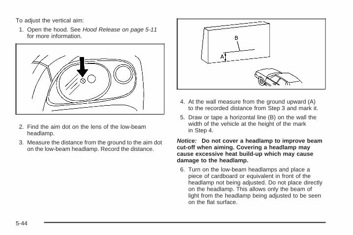
To adjust the vertical aim:
1. Open the hood. See Hood Release on page 5-11for more information.
2. Find the aim dot on the lens of the low-beamheadlamp.
3. Measure the distance from the ground to the aim doton the low-beam headlamp. Record the distance.
4. At the wall measure from the ground upward (A)to the recorded distance from Step 3 and mark it.
5. Draw or tape a horizontal line (B) on the wall thewidth of the vehicle at the height of the markin Step 4.
Notice: Do not cover a headlamp to improve beamcut-off when aiming. Covering a headlamp maycause excessive heat build-up which may causedamage to the headlamp.
6. Turn on the low-beam headlamps and place apiece of cardboard or equivalent in front of theheadlamp not being adjusted. Do not place directlyon the headlamp. This allows only the beam oflight from the headlamp being adjusted to be seenon the flat surface.
5-44

7. Locate the vertical headlamp aiming screws, whichare under the hood near each headlamp assembly.The adjustment screw can be turned with a6 mm hex socket.
8. Turn the vertical aiming screw until the headlampbeam is aimed to the horizontal tape line. Turn itclockwise or counterclockwise to raise or lower theangle of the beam.
The top edge of the cut-off should be positioned atthe bottom edge of the horizontal tape line.
9. Make sure that the light from the headlamp ispositioned at the bottom edge of the horizontal tapeline. The lamp on the left (A) shows the correctheadlamp aim. The lamp on the right (B) shows theincorrect headlamp aim.
10. Repeat Steps 7 through 9 for the opposite headlamp.
Driver Side Shown
5-45
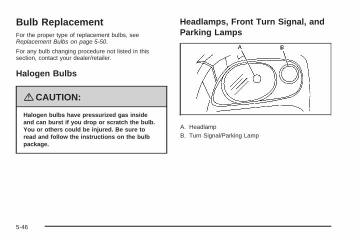
Bulb ReplacementFor the proper type of replacement bulbs, seeReplacement Bulbs on page 5-50.
For any bulb changing procedure not listed in thissection, contact your dealer/retailer.
Halogen Bulbs
{CAUTION:
Halogen bulbs have pressurized gas insideand can burst if you drop or scratch the bulb.You or others could be injured. Be sure toread and follow the instructions on the bulbpackage.
Headlamps, Front Turn Signal, andParking Lamps
A. HeadlampB. Turn Signal/Parking Lamp
5-46
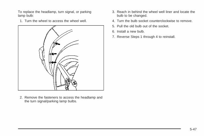
To replace the headlamp, turn signal, or parkinglamp bulb:
1. Turn the wheel to access the wheel well.
2. Remove the fasteners to access the headlamp andthe turn signal/parking lamp bulbs.
3. Reach in behind the wheel well liner and locate thebulb to be changed.
4. Turn the bulb socket counterclockwise to remove.
5. Pull the old bulb out of the socket.
6. Install a new bulb.
7. Reverse Steps 1 through 4 to reinstall.
5-47

Center High-Mounted Stoplamp(CHMSL)To replace the center high-mounted stoplamp bulb:
1. Open the liftgate. See Liftgate on page 2-12for more information.
2. Remove the center trim located near the top ofthe liftgate.
3. Locate the bulb assembly.
4. Locate the bulb you wish to change.
5. Turn the bulb socket counterclockwise to remove.
6. Pull the bulb straight out of the socket.
7. Install a new bulb.
8. Reverse the steps to reinstall.
5-48

Taillamps, Turn Signal, Stoplampsand Back-up Lamps
A. Stoplamp/Taillamp/Turn Signal LampB. Back-up Lamp
To replace one of these bulbs:
1. Open the liftgate. See Liftgate on page 2-12 formore information.
2. Remove the cover in the rear cargo area of thevehicle to access the bulbs.
3. Turn the bulb socket counterclockwise and pull itout of the lamp housing.
4. Pull the bulb straight out of the socket.
5. Install a new bulb. When installing the bulb socketinto the assembly, line up the tabs with the slots inthe bulb assembly.
6. Reverse the steps to reinstall.
5-49

License Plate LampTo replace one of these bulbs:
1. Remove the two screws holding each of the licenseplate lamps to the fascia.
2. Turn and pull the license plate lamp forwardthrough the fascia opening.
3. Turn the bulb socket counterclockwise and pull thebulb straight out of the socket.
4. Install the new bulb.
5. Reverse Steps 1 through 3 to reinstall the licenseplate lamp.
Replacement Bulbs
Exterior Lamp Bulb Number
Back-up Lamp and CHMSL 921
Front Turn Signal and ParkingLamp (Amber) 5702KA
Front Turn Signal and ParkingLamp (Clear) B2N
Headlamp High/Low-Beam H13
Stoplamp/Taillamp/Turn Signal 3057KX
For replacement bulbs not listed here, contact yourdealer/retailer.
Windshield Wiper BladeReplacementWindshield wiper blades should be inspected for wearor cracking. See Scheduled Maintenance on page 6-4for more information on wiper blade inspection.
5-50

Replacement blades come in different types and areremoved in different ways. For the proper type andlength, see Maintenance Replacement Parts onpage 6-14. Here’s how to remove the wiper blade:
1. Pull the windshield wiper arm away from thewindshield.
2. While holding the wiper arm, lift the clip up from theblade connecting point, and pull the blade assemblydown toward the windshield to remove it from thewiper arm.
3. Install the new wiper blade on the wiper armand press down on the clip to snap it into place.
Backglass Wiper Blade Replacement1. Remove the protective cap from the wiper arm.
If the protective cap is not removed before liftingthe wiper arm, the wiper arm could be damaged.
2. Pull the wiper arm away from the backglass andinto the service position.
3. Rotate the wiper blade, and pull down on it toremove it from the wiper arm.
4. Install the new wiper blade, then set the wiper armback into its original position and replace theprotective cap.
5-51

TiresYour new vehicle comes with high-quality tiresmade by a leading tire manufacturer. If you everhave questions about your tire warranty and whereto obtain service, see your vehicle Warrantybooklet for details.
{CAUTION:
Poorly maintained and improperly usedtires are dangerous.
• Overloading your vehicle’s tires cancause overheating as a result oftoo much flexing. You could have anair-out and a serious accident. SeeLoading Your Vehicle on page 4-27.
CAUTION: (Continued)
CAUTION: (Continued)
• Underinflated tires pose the samedanger as overloaded tires. Theresulting accident could cause seriousinjury. Check all tires frequently tomaintain the recommended pressure.Tire pressure should be checkedwhen your vehicle’s tires are cold.See Inflation - Tire Pressure onpage 5-60.
• Overinflated tires are more likely tobe cut, punctured, or broken by asudden impact — such as when youhit a pothole. Keep tires at therecommended pressure.
• Worn, old tires can cause accidents.If the tire’s tread is badly worn,or if your vehicle’s tires have beendamaged, replace them.
5-52

Low-Profile Performance TireIf your vehicle has P225/45R18 size tires, they areclassified as low-profile performance tires. Thesetires are designed for very responsive driving onwet or dry pavement. You may also notice moreroad noise with low-profile performance tires andthat they tend to wear faster.
Notice: If your vehicle has low-profile tires,they are more susceptible to damage from roadhazards or curb impact than standard profiletires. Tire and/or wheel assembly damagecan occur when coming into contact withroad hazards like, potholes, or sharp edgedobjects, or when sliding into a curb. Yourvehicle warranty does not cover this type ofdamage. Keep tires set to the correct inflationpressure and, when possible avoid contactwith curbs, potholes, and other road hazards.
Tire Sidewall LabelingUseful information about a tire is molded into itssidewall. The examples below show a typicalpassenger vehicle tire and a compact spare tiresidewall.
(A) Tire Size: The tire size is a combination ofletters and numbers used to define a particulartire’s width, height, aspect ratio, construction type,and service description. See the “Tire Size”illustration later in this section for more detail.
Passenger (P-Metric) Tire Example
5-53

(B) TPC Spec (Tire Performance CriteriaSpecification): Original equipment tires designedto GM’s specific tire performance criteria havea TPC specification code molded onto the sidewall.GM’s TPC specifications meet or exceed allfederal safety guidelines.
(C) DOT (Department of Transportation):The Department of Transportation (DOT) codeindicates that the tire is in compliance with theU.S. Department of Transportation Motor VehicleSafety Standards.
(D) Tire Identification Number (TIN): The lettersand numbers following DOT (Department ofTransportation) code is the Tire IdentificationNumber (TIN). The TIN shows the manufacturerand plant code, tire size, and date the tirewas manufactured. The TIN is molded onto bothsides of the tire, although only one side may havethe date of manufacture.
(E) Tire Ply Material: The type of cord and numberof plies in the sidewall and under the tread.
(F) Uniform Tire Quality Grading (UTQG):Tire manufacturers are required to gradetires based on three performance factors:treadwear, traction, and temperature resistance.For more information see Uniform Tire QualityGrading on page 5-71.
(G) Maximum Cold Inflation Load Limit:Maximum load that can be carried and themaximum pressure needed to support that load.
(A) Temporary Use Only: The compact sparetire or temporary use tire has a tread life ofapproximately 3,000 miles (5 000 km) and shouldnot be driven at speeds over 65 mph (105 km/h).
Compact Spare Tire Example
5-54
The compact spare tire is for emergency usewhen a regular road tire has lost air and gone flat.If your vehicle has a compact spare tire, seeCompact Spare Tire on page 5-109 and If a TireGoes Flat on page 5-75.
(B) Tire Ply Material: The type of cord andnumber of plies in the sidewall and under the tread.
(C) Tire Identification Number (TIN): The lettersand numbers following the DOT (Departmentof Transportation) code is the Tire IdentificationNumber (TIN). The TIN shows the manufacturerand plant code, tire size, and date the tire wasmanufactured. The TIN is molded onto both sidesof the tire, although only one side may havethe date of manufacture.
(D) Maximum Cold Inflation Load Limit:Maximum load that can be carried and themaximum pressure needed to support that load.
(E) Tire Inflation: The temporary use tire orcompact spare tire should be inflated to 60 psi(420 kPa). For more information on tire pressureand inflation see Inflation - Tire Pressure onpage 5-60.
(F) Tire Size : A combination of letters andnumbers define a tire’s width, height, aspectratio, construction type, and service description.The letter T as the first character in the tiresize means the tire is for temporary use only.
(G) TPC Spec (Tire Performance CriteriaSpecification): Original equipment tires designedto GM’s specific tire performance criteria havea TPC specification code molded onto the sidewall.GM’s TPC specifications meet or exceed allfederal safety guidelines.
5-55

Tire SizeThe following illustration shows an example of atypical passenger vehicle tire size.
(A) Passenger (P-Metric) Tire: The United Statesversion of a metric tire sizing system. The letter Pas the first character in the tire size means apassenger vehicle tire engineered to standards setby the U.S. Tire and Rim Association.
(B) Tire Width: The three-digit number indicatesthe tire section width in millimeters from sidewallto sidewall.
(C) Aspect Ratio: A two-digit number thatindicates the tire height-to-width measurements.For example, if the tire size aspect ratio is 60,as shown in item C of the illustration, it wouldmean that the tire’s sidewall is 60 percent as highas it is wide.
(D) Construction Code: A letter code is used toindicate the type of ply construction in the tire.The letter R means radial ply construction;the letter D means diagonal or bias plyconstruction; and the letter B means belted-biasply construction.
(E) Rim Diameter: Diameter of the wheel ininches.
(F) Service Description: These charactersrepresent the load range and speed rating of thetire. The load index represents the load carrycapacity a tire is certified to carry. The load indexcan range from 1 to 279. The speed rating isthe maximum speed a tire is certified to carry aload. Speed ratings range from A to Z.
5-56

Tire Terminology and Definitions
Air Pressure: The amount of air inside thetire pressing outward on each square inch of thetire. Air pressure is expressed in pounds persquare inch (psi) or kilopascal (kPa).
Accessory Weight: This means the combinedweight of optional accessories. Some examples ofoptional accessories are, automatic transmission,power steering, power brakes, power windows,power seats, and air conditioning.
Aspect Ratio: The relationship of a tire’s heightto its width.
Belt: A rubber coated layer of cords that is locatedbetween the plies and the tread. Cords may bemade from steel or other reinforcing materials.
Bead: The tire bead contains steel wires wrappedby steel cords that hold the tire onto the rim.
Bias Ply Tire: A pneumatic tire in which the pliesare laid at alternate angles less than 90 degreesto the centerline of the tread.
Cold Tire Pressure: The amount of air pressurein a tire, measured in pounds per square inch(psi) or kilopascals (kPa) before a tire has built upheat from driving. See Inflation - Tire Pressureon page 5-60.
Curb Weight: The weight of a motor vehicle withstandard and optional equipment including themaximum capacity of fuel, oil, and coolant,but without passengers and cargo.
DOT Markings: A code molded into the sidewallof a tire signifying that the tire is in compliancewith the U.S. Department of Transportation (DOT)motor vehicle safety standards. The DOT codeincludes the Tire Identification Number (TIN),an alphanumeric designator which can also identifythe tire manufacturer, production plant, brand,and date of production.
GVWR: Gross Vehicle Weight Rating.See Loading Your Vehicle on page 4-27.
GAWR FRT: Gross Axle Weight Rating forthe front axle. See Loading Your Vehicle onpage 4-27.
5-57

GAWR RR: Gross Axle Weight Rating for the rearaxle. See Loading Your Vehicle on page 4-27.
Intended Outboard Sidewall: The side ofan asymmetrical tire, that must always faceoutward when mounted on a vehicle.
Kilopascal (kPa): The metric unit for air pressure.
Light Truck (LT-Metric) Tire: A tire used onlight duty trucks and some multipurpose passengervehicles.
Load Index: An assigned number ranging from1 to 279 that corresponds to the load carryingcapacity of a tire.
Maximum Inflation Pressure: The maximum airpressure to which a cold tire can be inflated.The maximum air pressure is molded onto thesidewall.
Maximum Load Rating: The load rating for a tireat the maximum permissible inflation pressurefor that tire.
Maximum Loaded Vehicle Weight: The sum ofcurb weight, accessory weight, vehicle capacityweight, and production options weight.
Normal Occupant Weight: The number ofoccupants a vehicle is designed to seat multipliedby 150 lbs (68 kg). See Loading Your Vehicleon page 4-27.
Occupant Distribution: Designated seatingpositions.
Outward Facing Sidewall: The side of anasymmetrical tire that has a particular side thatfaces outward when mounted on a vehicle.The side of the tire that contains a whitewall, bearswhite lettering, or bears manufacturer, brand,and/or model name molding that is higheror deeper than the same moldings on the othersidewall of the tire.
Passenger (P-Metric) Tire: A tire used onpassenger cars and some light duty trucks andmultipurpose vehicles.
Recommended Inflation Pressure: Vehiclemanufacturer’s recommended tire inflationpressure as shown on the tire placard. SeeInflation - Tire Pressure on page 5-60 and LoadingYour Vehicle on page 4-27.
5-58

Radial Ply Tire: A pneumatic tire in which theply cords that extend to the beads are laid at90 degrees to the centerline of the tread.
Rim: A metal support for a tire and upon whichthe tire beads are seated.
Sidewall: The portion of a tire between the treadand the bead.
Speed Rating: An alphanumeric code assigned toa tire indicating the maximum speed at which atire can operate.
Traction: The friction between the tire and theroad surface. The amount of grip provided.
Tread: The portion of a tire that comes intocontact with the road.
Treadwear Indicators: Narrow bands, sometimescalled wear bars, that show across the tread ofa tire when only 1/16 inch (1.6 mm) of treadremains. See When It Is Time for New Tires onpage 5-68.
UTQGS (Uniform Tire Quality GradingStandards): A tire information system thatprovides consumers with ratings for a tire’straction, temperature, and treadwear. Ratingsare determined by tire manufacturers usinggovernment testing procedures. The ratings aremolded into the sidewall of the tire. See UniformTire Quality Grading on page 5-71.
Vehicle Capacity Weight: The number ofdesignated seating positions multiplied by 150 lbs(68 kg) plus the rated cargo load. See LoadingYour Vehicle on page 4-27.
Vehicle Maximum Load on the Tire: Load onan individual tire due to curb weight, accessoryweight, occupant weight, and cargo weight.
Vehicle Placard: A label permanently attachedto a vehicle showing the vehicle’s capacityweight and the original equipment tire size andrecommended inflation pressure. See “Tire andLoading Information Label” under LoadingYour Vehicle on page 4-27.
5-59

Inflation - Tire PressureTires need the correct amount of air pressure tooperate effectively.
Notice: Do not let anyone tell you thatunder-inflation or over-inflation is all right.It is not. If your tires do not have enough air(under-inflation), you can get the following:• Too much flexing• Too much heat• Tire overloading• Premature or irregular wear• Poor handling• Reduced fuel economy
If your tires have too much air (over-inflation),you can get the following:• Unusual wear• Poor handling• Rough ride• Needless damage from road hazards
A vehicle specific Tire and Loading Informationlabel is attached to your vehicle. This label showsyour vehicle’s original equipment tires and thecorrect inflation pressures for your tires when theyare cold. The recommended cold tire inflationpressure, shown on the label, is the minimumamount of air pressure needed to supportyour vehicle’s maximum load carrying capacity.
For additional information regarding how muchweight your vehicle can carry, and an exampleof the Tire and Loading Information label,see Loading Your Vehicle on page 4-27. How youload your vehicle affects vehicle handling andride comfort. Never load your vehicle with moreweight than it was designed to carry.
When to CheckCheck your tires once a month or more. Do notforget to check the compact spare tire, it should beat 60 psi (420 kPa). For additional informationregarding the compact spare tire, see CompactSpare Tire on page 5-109.
5-60
How to CheckUse a good quality pocket-type gage to checktire pressure. You cannot tell if your tires areproperly inflated simply by looking at them.Radial tires may look properly inflated even whenthey are under-inflated. Check the tire’s inflationpressure when the tires are cold. Cold means yourvehicle has been sitting for at least three hoursor driven no more than 1 mile (1.6 km).
Remove the valve cap from the tire valve stem.Press the tire gage firmly onto the valve toget a pressure measurement. If the cold tireinflation pressure matches the recommendedpressure on the Tire and Loading Informationlabel, no further adjustment is necessary. If theinflation pressure is low, add air until you reach therecommended amount.
If you overfill the tire, release air by pushing onthe metal stem in the center of the tire valve.Re-check the tire pressure with the tire gage.
Be sure to put the valve caps back on the valvestems. They help prevent leaks by keeping out dirtand moisture.
Tire Pressure Monitor SystemThe Tire Pressure Monitor System (TPMS) uses radioand sensor technology to check tire pressure levels.The TPMS sensors monitor the air pressure inyour vehicle’s tires and transmit tire pressure readingsto a receiver located in the vehicle.
Each tire, including the spare (if provided), should bechecked monthly when cold and inflated to the inflationpressure recommended by the vehicle manufactureron the vehicle placard or tire inflation pressure label.(If your vehicle has tires of a different size than thesize indicated on the vehicle placard or tire inflationpressure label, you should determine the propertire inflation pressure for those tires.)
As an added safety feature, your vehicle has beenequipped with a tire pressure monitoring system (TPMS)that illuminates a low tire pressure telltale when oneor more of your tires is significantly under-inflated.
Accordingly, when the low tire pressure telltaleilluminates, you should stop and check your tires assoon as possible, and inflate them to the properpressure. Driving on a significantly under-inflated tirecauses the tire to overheat and can lead to tire failure.Under-inflation also reduces fuel efficiency and tiretread life, and may affect the vehicle’s handlingand stopping ability.
5-61

Please note that the TPMS is not a substitute for propertire maintenance, and it is the driver’s responsibility tomaintain correct tire pressure, even if under-inflationhas not reached the level to trigger illumination ofthe TPMS low tire pressure telltale.
Your vehicle has also been equipped with a TPMSmalfunction indicator to indicate when the system is notoperating properly. The TPMS malfunction indicatoris combined with the low tire pressure telltale. When thesystem detects a malfunction, the telltale will flashfor approximately one minute and then remaincontinuously illuminated. This sequence will continueupon subsequent vehicle start-ups as long as themalfunction exists.
When the malfunction indicator is illuminated, thesystem may not be able to detect or signal low tirepressure as intended. TPMS malfunctions may occurfor a variety of reasons, including the installationof replacement or alternate tires or wheels on the vehiclethat prevent the TPMS from functioning properly.Always check the TPMS malfunction telltale afterreplacing one or more tires or wheels on your vehicle toensure that the replacement or alternate tires andwheels allow the TPMS to continue to function properly.
See Tire Pressure Monitor Operation on page 5-63,for additional information.
Federal Communications Commission(FCC) and Industry and ScienceCanadaThe Tire Pressure Monitor System (TPMS) operates ona radio frequency and complies with Part 15 of theFCC Rules. Operation is subject to the followingtwo conditions:
1. This device may not cause harmful interference.
2. This device must accept any interference received,including interference that may cause undesiredoperation.
The Tire Pressure Monitor System (TPMS) operates ona radio frequency and complies with RSS-210 ofIndustry and Science Canada. Operation is subject tothe following two conditions:
1. This device may not cause interference.
2. This device must accept any interference received,including interference that may cause undesiredoperation of the device.
Changes or modifications to this system by other thanan authorized service facility could void authorization touse this equipment.
5-62
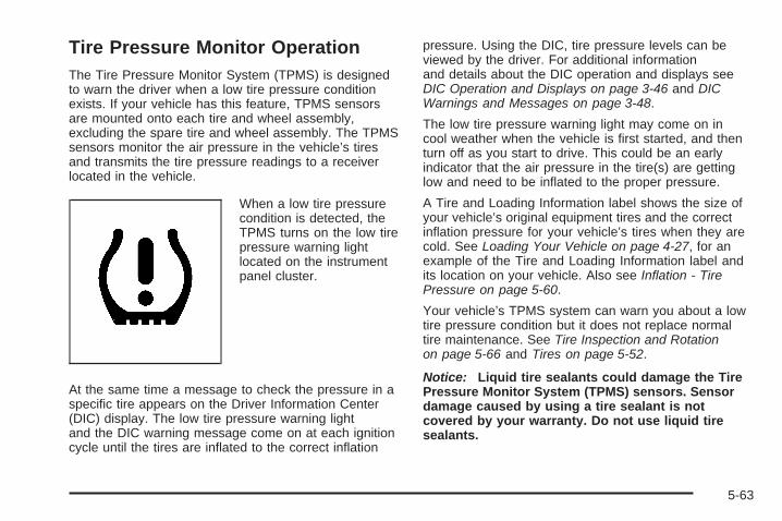
Tire Pressure Monitor OperationThe Tire Pressure Monitor System (TPMS) is designedto warn the driver when a low tire pressure conditionexists. If your vehicle has this feature, TPMS sensorsare mounted onto each tire and wheel assembly,excluding the spare tire and wheel assembly. The TPMSsensors monitor the air pressure in the vehicle’s tiresand transmits the tire pressure readings to a receiverlocated in the vehicle.
When a low tire pressurecondition is detected, theTPMS turns on the low tirepressure warning lightlocated on the instrumentpanel cluster.
At the same time a message to check the pressure in aspecific tire appears on the Driver Information Center(DIC) display. The low tire pressure warning lightand the DIC warning message come on at each ignitioncycle until the tires are inflated to the correct inflation
pressure. Using the DIC, tire pressure levels can beviewed by the driver. For additional informationand details about the DIC operation and displays seeDIC Operation and Displays on page 3-46 and DICWarnings and Messages on page 3-48.
The low tire pressure warning light may come on incool weather when the vehicle is first started, and thenturn off as you start to drive. This could be an earlyindicator that the air pressure in the tire(s) are gettinglow and need to be inflated to the proper pressure.
A Tire and Loading Information label shows the size ofyour vehicle’s original equipment tires and the correctinflation pressure for your vehicle’s tires when they arecold. See Loading Your Vehicle on page 4-27, for anexample of the Tire and Loading Information label andits location on your vehicle. Also see Inflation - TirePressure on page 5-60.
Your vehicle’s TPMS system can warn you about a lowtire pressure condition but it does not replace normaltire maintenance. See Tire Inspection and Rotationon page 5-66 and Tires on page 5-52.
Notice: Liquid tire sealants could damage the TirePressure Monitor System (TPMS) sensors. Sensordamage caused by using a tire sealant is notcovered by your warranty. Do not use liquid tiresealants.
5-63

TPMS Malfunction Light and MessageThe TPMS will not function properly if one or more of theTPMS sensors are missing or inoperable. When thesystem detects a malfunction, the low tire warning lightflashes for about one minute and then stays on forthe remainder of the ignition cycle. A DIC warningmessage is also displayed. The low tire warning lightand DIC warning message come on at each ignitioncycle until the problem is corrected. Some of theconditions that can cause the malfunction light and DICmessage to come on are:
• One of the road tires has been replaced with thespare tire. The spare tire does not have a TPMSsensor. The TPMS malfunction light and DICmessage should go off once you re-install the roadtire containing the TPMS sensor.
• The TPMS sensor matching process was startedbut not completed or not completed successfullyafter rotating the vehicle’s tires. The DIC messageand TPMS malfunction light should go off oncethe TPMS sensor matching process is performedsuccessfully. See “TPMS Sensor Matching Process”later in this section.
• One or more TPMS sensors are missing ordamaged. The DIC message and the TPMSmalfunction light should go off when the TPMSsensors are installed and the sensor matchingprocess is performed successfully. See yourdealer/retailer for service.
• Replacement tires or wheels do not match yourvehicle’s original equipment tires or wheels.Tires and wheels other than those recommendedfor your vehicle could prevent the TPMS fromfunctioning properly. See Buying New Tires onpage 5-69.
• Operating electronic devices or being near facilitiesusing radio wave frequencies similar to the TPMScould cause the TPMS sensors to malfunction.
If the TPMS is not functioning it cannot detect orsignal a low tire condition. See your dealer/retailer forservice if the TPMS malfunction light and DIC messagecomes on and stays on.
5-64
TPMS Sensor Matching ProcessEach TPMS sensor has a unique identification code.Any time you replace one or more of the TPMS sensorsor rotate the vehicle’s tires, the identification codesneed to be matched to the new tire/wheel location.The sensors are matched, to the tire/wheel locations,in the following order: driver side front tire, passengerside front tire, passenger side rear tire, and driverside rear tire using a TPMS diagnostic tool. See yourdealer/retailer for service.
The TPMS sensors can also be matched to eachtire/wheel position by increasing or decreasing the tire’sair pressure. When increasing the tire’s pressure, donot exceed the maximum inflation pressure indicated onthe tire’s sidewall. To decrease the tire’s air-pressureuse the pointed end of the valve cap, a pencil-styleair pressure gage, or a key.
You have two minutes to match each tire and wheelposition. If it takes longer than two minutes to match anytire and wheel position, the matching process stopsand you need to start over.
The TPMS matching process is outlined below:
1. Set the parking brake.
2. Turn the ignition switch to ON/RUN with theengine off.
3. Press and hold the Remote Keyless Entry (RKE)transmitter’s LOCK and UNLOCK buttons, at thesame time, for about five seconds to start the TPMSlearn mode. The horn sounds twice indicating theTPMS receiver is ready and in learn mode.
4. Start with the driver side front tire. The driver sidefront turn signal also comes on to indicate thatcorner’s sensor is ready to be learned.
5. Remove the valve cap from the tire’s valve stem.Activate the TPMS sensor by increasing ordecreasing the tire’s air pressure for abouteight seconds. The horn chirp, can take up to30 seconds to sound. It chirps one time and thenall the turn signals flash one time to confirm thesensor identification code has been matched to thetire/wheel position.
6. The passenger side front turn signal comes on toindicate that corner sensor is ready to be learned.Proceed to the passenger side front tire andrepeat the procedure in Step 5.
5-65
7. The passenger side rear turn signal comes on toindicate that corner sensor is ready to be learned.Proceed to the passenger side rear tire andrepeat the procedure in Step 5.
8. The driver side rear turn signal comes on toindicate that corner sensor is ready to be learned.Proceed to the driver side rear tire, and repeatthe procedure in Step 5.
9. After hearing the single horn chirp for the driverside rear tire, two additional horn chirps sound toindicate the tire learning process is done. Turn theignition switch to LOCK/OFF.If no tires are learned after entering the TPMSlearn mode, or if communication with the receiverstops, or if the time limit has expired, turn theignition switch to LOCK/OFF and start overbeginning with Step 2.
10. Set all four tires to the recommended air pressurelevel as indicated on the Tire and LoadingInformation label.
11. Put the valve caps back on the valve stems.
Tire Inspection and RotationWe recommend that you regularly inspect yourvehicle’s tires, including the spare tire, for signs ofwear or damage. See When It Is Time for NewTires on page 5-68 for more information.
Tires should be rotated every 5,000 to 8,000 miles(8 000 to 13 000 km). See Scheduled Maintenanceon page 6-4.
The purpose of a regular tire rotation is toachieve a uniform wear for all tires on the vehicle.This will ensure that your vehicle continues toperform most like it did when the tires were new.
Any time you notice unusual wear, rotate thetires as soon as possible and check wheelalignment. Also check for damaged tires or wheels.See When It Is Time for New Tires on page 5-68and Wheel Replacement on page 5-73.
5-66

When rotating your vehicle’s tires, always usethe correct rotation pattern shown here.
Do not include the compact spare tire in thetire rotation.
After the tires have been rotated, adjust thefront and rear inflation pressures as shownon the Tire and Loading Information label.See Inflation - Tire Pressure on page 5-60 andLoading Your Vehicle on page 4-27.
Reset the Tire Pressure Monitor System.See Tire Pressure Monitor Operation onpage 5-63.
Make certain that all wheel nuts are properlytightened. See “Wheel Nut Torque” underCapacities and Specifications on page 5-125.
{CAUTION:
Rust or dirt on a wheel, or on the parts towhich it is fastened, can make wheel nutsbecome loose after time. The wheel couldcome off and cause an accident. Whenyou change a wheel, remove any rust ordirt from places where the wheel attachesto the vehicle. In an emergency, you canuse a cloth or a paper towel to do this;but be sure to use a scraper or wire brushlater, if needed, to get all the rust or dirtoff. See Changing a Flat Tire on page 5-86.
5-67
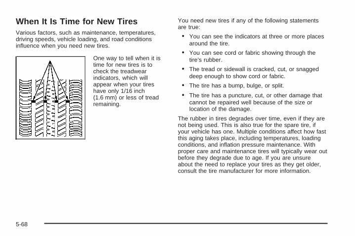
When It Is Time for New TiresVarious factors, such as maintenance, temperatures,driving speeds, vehicle loading, and road conditionsinfluence when you need new tires.
One way to tell when it istime for new tires is tocheck the treadwearindicators, which willappear when your tireshave only 1/16 inch(1.6 mm) or less of treadremaining.
You need new tires if any of the following statementsare true:
• You can see the indicators at three or more placesaround the tire.
• You can see cord or fabric showing through thetire’s rubber.
• The tread or sidewall is cracked, cut, or snaggeddeep enough to show cord or fabric.
• The tire has a bump, bulge, or split.
• The tire has a puncture, cut, or other damage thatcannot be repaired well because of the size orlocation of the damage.
The rubber in tires degrades over time, even if they arenot being used. This is also true for the spare tire, ifyour vehicle has one. Multiple conditions affect how fastthis aging takes place, including temperatures, loadingconditions, and inflation pressure maintenance. Withproper care and maintenance tires will typically wear outbefore they degrade due to age. If you are unsureabout the need to replace your tires as they get older,consult the tire manufacturer for more information.
5-68

Buying New TiresGM has developed and matched specific tiresfor your vehicle. The original equipment tiresinstalled on your vehicle, when it was new,were designed to meet General Motors TirePerformance Criteria Specification (TPC Spec)system rating. If you need replacement tires,GM strongly recommends that you get tires withthe same TPC Spec rating. This way, your vehiclewill continue to have tires that are designed togive the same performance and vehicle safety,during normal use, as the original tires.
GM’s exclusive TPC Spec system considers overa dozen critical specifications that impact theoverall performance of your vehicle, includingbrake system performance, ride and handling,traction control, and tire pressure monitoringperformance. GM’s TPC Spec number is moldedonto the tire’s sidewall near the tire size. If thetires have an all-season tread design, theTPC Spec number will be followed by an MS formud and snow. See Tire Sidewall Labeling onpage 5-53 for additional information.
GM recommends replacing tires in sets of four.This is because uniform tread depth on all tires willhelp keep your vehicle performing most like itdid when the tires were new. Replacing less thana full set of tires can affect the braking andhandling performance of your vehicle. See TireInspection and Rotation on page 5-66 forinformation on proper tire rotation.
{CAUTION:
Mixing tires could cause you to losecontrol while driving. If you mix tires ofdifferent sizes, brands, or types (radial andbias-belted tires), the vehicle may nothandle properly, and you could have acrash. Using tires of different sizes,brands, or types may also cause damage toyour vehicle. Be sure to use the correctsize, brand, and type of tires on all wheels.It is all right to drive with your compactspare temporarily, as it was developed foruse on your vehicle. See Compact SpareTire on page 5-109.
5-69
{CAUTION:
If you use bias-ply tires on your vehicle,the wheel rim flanges could developcracks after many miles of driving. A tireand/or wheel could fail suddenly, causinga crash. Use only radial-ply tires with thewheels on your vehicle.
If you must replace your vehicle’s tires withthose that do not have a TPC Spec number,make sure they are the same size, load range,speed rating, and construction type (radialand bias-belted tires) as your vehicle’soriginal tires.
Vehicles that have a tire pressure monitoringsystem could give an inaccurate low-pressurewarning if non-TPC Spec rated tires are installedon your vehicle. Non-TPC Spec rated tiresmay give a low-pressure warning that is higher orlower than the proper warning level you wouldget with TPC Spec rated tires. See Tire PressureMonitor System on page 5-61.
Your vehicle’s original equipment tires are listedon the Tire and Loading Information Label.See Loading Your Vehicle on page 4-27, formore information about the Tire and LoadingInformation Label and its location on your vehicle.
5-70

Different Size Tires and WheelsIf you add wheels or tires that are a different size thanyour original equipment wheels and tires, this couldaffect the way your vehicle performs, including itsbraking, ride and handling characteristics, stability, andresistance to rollover. Additionally, if your vehicle haselectronic systems such as anti-lock brakes, rolloverairbags, traction control, and electronic stability control,the performance of these systems can be affected.
{CAUTION:
If you add different sized wheels, your vehiclemay not provide an acceptable level ofperformance and safety if tires notrecommended for those wheels are selected.You may increase the chance that you willcrash and suffer serious injury. Only use GMspecific wheel and tire systems developed foryour vehicle, and have them properly installedby a GM certified technician.
See Buying New Tires on page 5-69 and Accessoriesand Modifications on page 5-3 for additional information.
Uniform Tire Quality GradingQuality grades can be found where applicableon the tire sidewall between tread shoulderand maximum section width. For example:
Treadwear 200 Traction AA Temperature AThe following information relates to the systemdeveloped by the United States National HighwayTraffic Safety Administration (NHTSA), whichgrades tires by treadwear, traction, andtemperature performance. This applies only tovehicles sold in the United States. The grades aremolded on the sidewalls of most passenger cartires. The Uniform Tire Quality Grading (UTQG)system does not apply to deep tread, winter-typesnow tires, space-saver, or temporary usespare tires, tires with nominal rim diameters of10 to 12 inches (25 to 30 cm), or to somelimited-production tires.
While the tires available on General Motorspassenger cars and light trucks may vary withrespect to these grades, they must also conformto federal safety requirements and additionalGeneral Motors Tire Performance Criteria (TPC)standards.
5-71

TreadwearThe treadwear grade is a comparative ratingbased on the wear rate of the tire when testedunder controlled conditions on a specifiedgovernment test course. For example, a tiregraded 150 would wear one and a half (1.5) timesas well on the government course as a tiregraded 100. The relative performance of tiresdepends upon the actual conditions of their use,however, and may depart significantly from thenorm due to variations in driving habits, servicepractices, and differences in road characteristicsand climate.
Traction – AA, A, B, CThe traction grades, from highest to lowest, areAA, A, B, and C. Those grades represent the tire’sability to stop on wet pavement as measured undercontrolled conditions on specified government testsurfaces of asphalt and concrete. A tire marked Cmay have poor traction performance.
Warning: The traction grade assigned to thistire is based on straight-ahead braking tractiontests, and does not include acceleration,cornering, hydroplaning, or peak tractioncharacteristics.
Temperature – A, B, CThe temperature grades are A (the highest), B,and C, representing the tire’s resistance tothe generation of heat and its ability to dissipateheat when tested under controlled conditions on aspecified indoor laboratory test wheel. Sustainedhigh temperature can cause the material of the tireto degenerate and reduce tire life, and excessivetemperature can lead to sudden tire failure.The grade C corresponds to a level of performancewhich all passenger car tires must meet underthe Federal Motor Vehicle Safety StandardNo. 109. Grades B and A represent higher levelsof performance on the laboratory test wheelthan the minimum required by law.
Warning: The temperature grade for thistire is established for a tire that is properlyinflated and not overloaded. Excessive speed,underinflation, or excessive loading, eitherseparately or in combination, can cause heatbuildup and possible tire failure.
5-72

Wheel Alignment and Tire BalanceThe tires and wheels on your vehicle were alignedand balanced carefully at the factory to give you thelongest tire life and best overall performance.Adjustments to wheel alignment and tire balancing willnot be necessary on a regular basis. However, ifyou notice unusual tire wear or your vehicle pulling toone side or the other, the alignment might need tobe checked. If you notice your vehicle vibrating whendriving on a smooth road, the tires and wheelsmight need to be rebalanced. See your dealer/retailerfor proper diagnosis.
Wheel ReplacementReplace any wheel that is bent, cracked, or badly rustedor corroded. If wheel nuts keep coming loose, thewheel, wheel bolts, and wheel nuts should be replaced.If the wheel leaks air, replace it (except somealuminum wheels, which can sometimes be repaired).See your dealer/retailer if any of these conditions exist.
Your dealer/retailer will know the kind of wheel you need.
Each new wheel should have the same load-carryingcapacity, diameter, width, offset, and be mountedthe same way as the one it replaces.
If you need to replace any of your wheels, wheel bolts,wheel nuts, or Tire Pressure Monitor System (TPMS)sensors, replace them only with new GM originalequipment parts. This way, you will be sure to have theright wheel, wheel bolts, wheel nuts, and TPMS sensorsfor your vehicle.
{CAUTION:
Using the wrong replacement wheels, wheelbolts, or wheel nuts on your vehicle can bedangerous. It could affect the braking andhandling of your vehicle, make your tires loseair and make you lose control. You could havea collision in which you or others could beinjured. Always use the correct wheel, wheelbolts, and wheel nuts for replacement.
Notice: The wrong wheel can also cause problemswith bearing life, brake cooling, speedometer orodometer calibration, headlamp aim, bumper height,vehicle ground clearance, and tire or tire chainclearance to the body and chassis.
See Changing a Flat Tire on page 5-86 for moreinformation.
5-73

Used Replacement Wheels
{CAUTION:
Putting a used wheel on your vehicle isdangerous. You cannot know how it has beenused or how far it has been driven. It could failsuddenly and cause a crash. If you have toreplace a wheel, use a new GM originalequipment wheel.
Tire Chains
{CAUTION:
Do not use tire chains. There is not enoughclearance. Tire chains used on a vehiclewithout the proper amount of clearance cancause damage to the brakes, suspension orother vehicle parts. The area damaged by thetire chains could cause you to lose control ofyour vehicle and you or others may be injuredin a crash.
Use another type of traction device only if itsmanufacturer recommends it for use on yourvehicle and tire size combination and roadconditions. Follow that manufacturer’sinstructions. To help avoid damage to yourvehicle, drive slowly, readjust or remove thedevice if it is contacting your vehicle, and donot spin your vehicle’s wheels. If you do findtraction devices that will fit, install them on thefront tires.
5-74

If a Tire Goes FlatIt is unusual for a tire to blowout while you are driving,especially if you maintain your vehicle’s tires properly.If air goes out of a tire, it is much more likely to leak outslowly. But if you should ever have a blowout, hereare a few tips about what to expect and what to do:
If a front tire fails, the flat tire creates a drag that pullsthe vehicle toward that side. Take your foot off theaccelerator pedal and grip the steering wheel firmly.Steer to maintain lane position, and then gently brake toa stop well out of the traffic lane.
A rear blowout, particularly on a curve, acts much like askid and may require the same correction you woulduse in a skid. In any rear blowout remove your foot fromthe accelerator pedal. Get the vehicle under controlby steering the way you want the vehicle to go. It maybe very bumpy and noisy, but you can still steer.Gently brake to a stop, well off the road if possible.
{CAUTION:
Lifting a vehicle and getting under it to domaintenance or repairs is dangerous withoutthe appropriate safety equipment and training.The jack provided with your vehicle isdesigned only for changing a flat tire. If it isused for anything else, you or others could bebadly injured or killed if the vehicle slips offthe jack. Use the jack provided with yourvehicle only for changing a flat tire.
If a tire goes flat, the next part shows how to use thejacking equipment to change a flat tire safely.
5-75

Tire Sealant and Compressor KitYour vehicle may have a tire sealant and compressor kitthat is capable of temporarily sealing a puncture up to1⁄4 inch (6 mm) in the tread area of the tire. If your vehiclehas this kit, there is no jack or spare tire. The kit inflatesthe tire with liquid sealant and air. The tire sealant andcompressor kit can also be used to inflate anunderinflated tire. After the tire is inflated to therecommended inflation pressure, see Inflation - TirePressure on page 5-60 for more information, the vehiclemust be driven for five miles to distribute the sealant inthe tire and to seal the puncture. After driving five miles,the tire pressure must be rechecked and adjusted asneeded. See Using the Tire Sealant and Compressorlater in this section. Be sure to read and follow all of thetire sealant and compressor kit instructions. The kitincludes the following:
A. Air CompressorB. Tire Sealant CanisterC. Air Compressor
Accessory PlugD. On/Off Switch
E. Air Pressure GageF. Air Compressor
Inflator HoseG. Sealant Filling Hose
After temporarily repairing a tire using the tire sealantand compressor kit, take your vehicle to an authorizeddealer/retailer as soon as possible. If the sealant isnot removed from the tire within 100 miles(161 kilometers) of driving, the dealer/retailer mayrecommend that the tire be replaced.
5-76
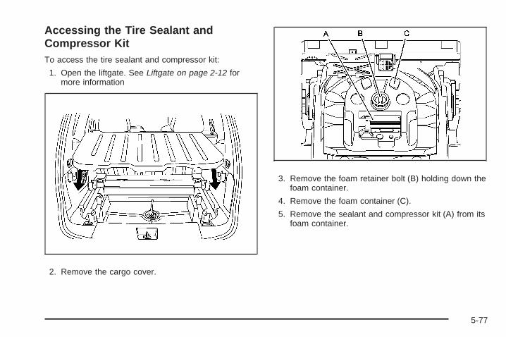
Accessing the Tire Sealant andCompressor KitTo access the tire sealant and compressor kit:
1. Open the liftgate. See Liftgate on page 2-12 formore information
2. Remove the cargo cover.
3. Remove the foam retainer bolt (B) holding down thefoam container.
4. Remove the foam container (C).
5. Remove the sealant and compressor kit (A) from itsfoam container.
5-77

Tire SealantRead and follow the safety handling instructions on thesealant canister.
The sealant can temporarily seal a puncture up to1⁄4 inch (6 mm) in the tread area of the tire. The sealantcannot seal sidewall damage, large punctures, or atire that has unseated from the wheel. See RoadsideAssistance Program on page 7-6 if you need assistance.
The sealant can only be used to seal one tire. Afterusage, the sealant canister and the sealant filling hoseassembly must be replaced at a dealer/retailer. SeeRemoval and Installation of Sealant Canister later in thissection.
Check the tire sealant expiration date on the sealantcanister, if it has expired, see your dealer/retailer for areplacement.
Using the Tire Sealant and CompressorKit to Temporarily Seal a Punctured TireFollow the directions closely for correct sealant usage.
1. Place the sealant and compressor kit on the groundand unwrap the sealant filling hose from thecompressor.
2. Remove the air compressor accessory plug fromthe unit. To do this, pull the top portion of thewrapped cord out first, then the bottom, and thenunsnap the plug. Do not insert the plug into anaccessory outlet yet.
3. Remove the valve stem or tire pressure monitoringsensor cap from the flat tire by turning itcounterclockwise.If an object, such as a nail, has penetrated the tire,do not remove it.
5-78

4. Attach the sealant filling hose (A) onto the tire valvestem. Turn it clockwise until it is tight.Make sure the sealant and compressor kit on/offswitch (B) is in the O (off) position.
5. Plug the air compressor accessory plug (C) into anaccessory power outlet in the vehicle. See AccessoryPower Outlet(s) on page 3-20 for more information.Do not slam door or close window on thecompressor accessory plug cord.
{CAUTION:
Idling the engine in a closed-in place or withthe climate control system off can causedeadly carbon monoxide (CO). See EngineExhaust on page 2-37.
6. Start the vehicle. See Starting the Engine (KeyAccess) on page 2-25 for more information.The vehicle must be running while using the aircompressor.
{CAUTION:
Inflating something too much can make itexplode, and you or others could be injured.Be sure to read the inflator instructions, andinflate the tire to its recommended pressure.Do not exceed 36 psi (248 kPa).
5-79

7. Push the On/Off switch to the I (on) position.The sealant and compressor kit injects sealantand air into the tire. Sealant can leak fromthe puncture until the vehicle is driven and the holehas sealed.The pressure gage will initially show a high pressurewhile the compressor pushes the sealant into thetire. Once the sealant is completely dispersedinto the tire, the pressure will quickly drop and startto rise again as the tire inflates with air.
8. Inflate the tire to the recommended inflationpressure, found on the Tire and Loading Informationlabel located on the vehicle’s center pillar (B-pillar)below the vehicle’s door latch, using the air pressuregage on the top of the unit.The pressure gage reads high while the compressoris running. Turn the compressor off to get anaccurate pressure reading.
Notice: If the recommended pressure cannot bereached after 15 minutes, the vehicle should not bedriven farther. Damage to the tire is severe andthe sealant will not be effective. Remove theair compressor plug from the accessory poweroutlet and unscrew the inflating hose from the tirevalve. See Roadside Assistance Program onpage 7-6 for more information.
9. Push the sealant and compressor kit switch to theO (off) position.
10. The tire is not sealed and will continue to leak airuntil the vehicle is driven and the sealant isdistributed in the tire.Steps 11 through 18 must be done right afterStep 9.
11. Unplug the air compressor accessory plug from theaccessory power outlet in the vehicle.
12. Disconnect the sealant filling hose from the tirevalve stem, by turning it counterclockwise, andreplace the tire valve stem cap.Be careful when handling the tire inflatorcomponents as they could be hot after usage.
13. Wrap the sealant filling hose around the aircompressor channel to stow it in its original location.
14. Stow the air compressor accessory plug back in theair compressor. To do this, wrap the air compressoraccessory plug, snap in the plug, and then pushin the bottom and then the top of the wrappedair compressor accessory plug.
5-80

15. If the flat tire was ableto inflate to therecommended inflationpressure, removethe maximum speedlabel from the sealantcanister.
The maximum speed label reminds you to drivecautiously and not to exceed 55 mph (90 km/h)until you have the damaged tire inspectedand repaired.
16. Place it in a highly visible location such as theinside of the upper left corner of the windshieldor to the face of the radio/clock.
17. Return the equipment to the proper storage locationin the rear of your vehicle. To do this, insert the tiresealant and compressor kit back into the foamcontainer and place the foam container onto thestorage bracket. Securely tighten down thefoam container with the foam retainer bolt.
{CAUTION:
Storing the tire sealant and compressor kitor other equipment in the passengercompartment of the vehicle could cause injury.In a sudden stop or collision, loose equipmentcould strike someone. Store the tire sealantand compressor kit in the proper place.
18. Reverse Steps 1 through 4 under Accessing theTire Sealant and Compressor Kit earlier in thissection.
19. Immediately drive the vehicle 5 miles (8 km) todistribute the sealant evenly in the tire. Stop at asafe location and check the tire pressure, referto Steps 1 through 8 under Using the AirCompressor without Sealant next in this section.If the tire pressure has not dropped more than10 psi (68 kPa) from the recommended inflationpressure, you can inflate the tire back up tothe recommended inflation pressure.
5-81

20. If the tire pressure has fallen more then 10 psi(68 kPa), below the recommended inflationpressure, stop driving the vehicle. The tire istoo severely damaged and the tire sealant andcompressor kit cannot seal the tire. See RoadsideAssistance Program on page 7-6 for moreinformation.
21. Wipe off any sealant from the wheel, tire andvehicle with a rag.
22. Dispose of the sealant canister at a localdealer/retailer or in accordance with any local, state,and provincial codes and practices.After using the sealant canister, replace it with anew canister from a dealer/retailer.
23. After temporarily sealing a tire with the tire sealantand compressor kit, take your vehicle to anauthorized dealer/retailer to have the tire inspectedand repaired.
Using the Air Compressor withoutSealant to Inflate an Underinflated Tire(Not Punctured)To use the air compressor to inflate a tire with air onlyand not sealant:1. Remove the air compressor inflating hose connector
from the bottom of the air compressor.
2. Unlock the air compressor hose from the sealantcanister by pulling up on the lever.
3. Pull the air compressor inflator hose from thesealant canister.
5-82

4. Push the air compressor inflator hose onto thetire valve stem and push the lever down tosecure in place.
5. Plug the air compressor accessory plug into anaccessory power outlet in the vehicle. See AccessoryPower Outlet(s) on page 3-20 for more information.
{CAUTION:
Idling the engine in a closed-in place or withthe climate control system off can causedeadly carbon monoxide (CO). See EngineExhaust on page 2-37.
6. Start the vehicle. See Starting the Engine (KeyAccess) on page 2-25 for more information.The vehicle must be running while using theair compressor.
{CAUTION:
Inflating something too much can make itexplode, and you or others could be injured.Be sure to read the inflator instructions, andinflate the tire to its recommended pressure.Do not exceed 36 psi (248 kPa).
7. Push the sealant and compressor kit switch tothe I (on) position.
8. Inflate the tire up to the recommended inflationpressure using the air pressure gage on the topof the unit.The pressure gage reads high while the compressoris running. Turn the compressor off to get anaccurate reading. See Inflation - Tire Pressure onpage 5-60 for more information.
5-83

9. Turn off the air compressor by moving the switch tothe O (off) position.
{CAUTION:
Storing the tire sealant and compressor kitor other equipment in the passengercompartment of the vehicle could cause injury.In a sudden stop or collision, loose equipmentcould strike someone. Store the tire sealantand compressor kit in the proper place.
10. Disconnect the compressor inflator hose and wrapthe hose in the bottom of the sealant andcompressor kit.
11. Place the equipment in its original location.
Removal and Installation of theSealant CanisterTo remove the sealant canister, do the following:
1. Unlock the air compressor inflator hose from thesealant canister by pulling the lever up.
2. Disconnect the air compressor inflator hose fromthe sealant canister.
3. Unwrap the sealant filling hose from thecompressor.
5-84
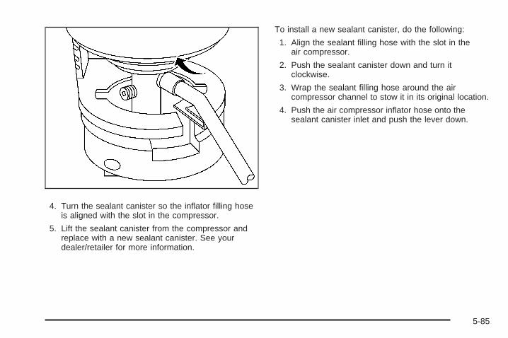
4. Turn the sealant canister so the inflator filling hoseis aligned with the slot in the compressor.
5. Lift the sealant canister from the compressor andreplace with a new sealant canister. See yourdealer/retailer for more information.
To install a new sealant canister, do the following:
1. Align the sealant filling hose with the slot in theair compressor.
2. Push the sealant canister down and turn itclockwise.
3. Wrap the sealant filling hose around the aircompressor channel to stow it in its original location.
4. Push the air compressor inflator hose onto thesealant canister inlet and push the lever down.
5-85

Changing a Flat Tire (Vehicles withspare tire)If a tire goes flat, avoid further tire and wheel damage bydriving slowly to a level place. Turn on your hazardwarning flashers.
{CAUTION:
Changing a tire can be dangerous. The vehiclecan slip off the jack and roll over or fall on youor other people. You and they could be badlyinjured or even killed. Find a level place tochange your tire. To help prevent the vehiclefrom moving:
1. Set the parking brake firmly.
2. Put an automatic transmission shift lever inPARK (P), or shift a manual transmission toFIRST (1) or REVERSE (R).
CAUTION: (Continued)
CAUTION: (Continued)
3. Turn off the engine and do not restartwhile the vehicle is raised.
4. Do not allow passengers to remain in thevehicle.
To be even more certain the vehicle will notmove, you should put blocks at the front andrear of the tire farthest away from the onebeing changed. That would be the tire on theother side, at the opposite end of the vehicle.
5-86

When you have a flat tire, use the following example asa guide to assist you in the placement of wheel blocks.
The following information will tell you how to use thejack and change a tire.
Removing the Spare Tire and ToolsIf your vehicle is equipped with a spare tire, the jack,wheel wrench, and spare tire are stowed in the rear ofthe vehicle, underneath the floor of the cargo area.To remove the spare tire and tools:
1. Open the liftgate. See Liftgate on page 2-12 formore information.
2. Remove the cargo cover.
5-87
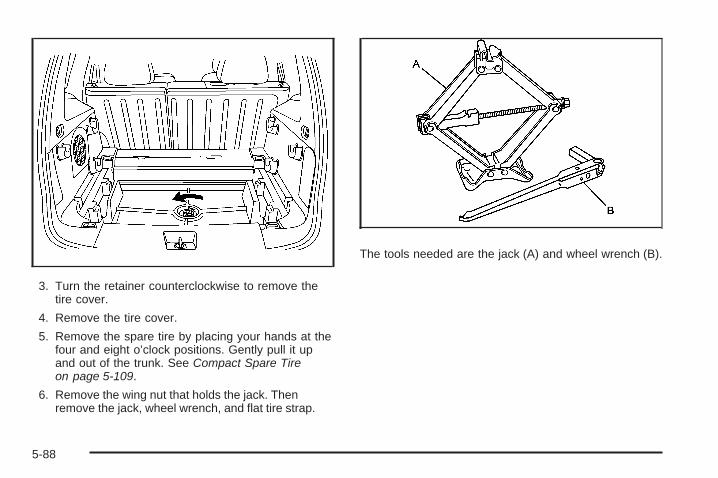
3. Turn the retainer counterclockwise to remove thetire cover.
4. Remove the tire cover.
5. Remove the spare tire by placing your hands at thefour and eight o’clock positions. Gently pull it upand out of the trunk. See Compact Spare Tireon page 5-109.
6. Remove the wing nut that holds the jack. Thenremove the jack, wheel wrench, and flat tire strap.
The tools needed are the jack (A) and wheel wrench (B).
5-88

Turn the plastic wheel nut counterclockwise to loosenthe wheel wrench from the jack.
Press the button and then pull on the end of the wheelwrench to extend the handle.
5-89

Removing the Flat Tire andInstalling the Spare Tire (SS Model)The SS Model has larger performance brakes thanthe Base Model. The compact spare tire will not clearthe front brakes.
Do not use the compact spare tire in the event of a frontflat tire.
You must use the rear tire to replace the front flat tire.
To change the rear road tire:
Rear Tire Changing Procedure1. Do a safety check before proceeding. See Changing
a Flat Tire on page 5-86 for more information.
2. Using the wheel wrench, loosen all the wheel nutson the rear tire. Do not remove them yet.
5-90

3. Position the jack on the rear position and raise thejack lift head to fit over the car flange under thedown arrow markings on the rocker panel.
{CAUTION:
Getting under a vehicle when it is jacked upis dangerous. If the vehicle slips off the jack,you could be badly injured or killed. Never getunder a vehicle when it is supported only bya jack.
5-91
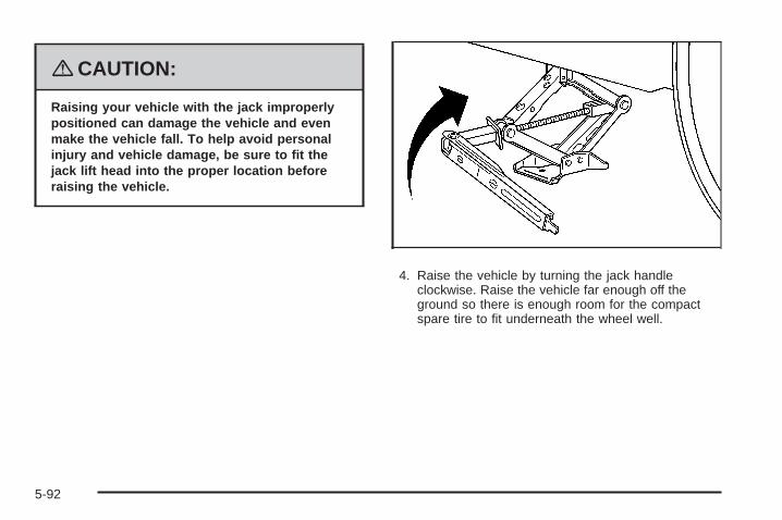
{CAUTION:
Raising your vehicle with the jack improperlypositioned can damage the vehicle and evenmake the vehicle fall. To help avoid personalinjury and vehicle damage, be sure to fit thejack lift head into the proper location beforeraising the vehicle.
4. Raise the vehicle by turning the jack handleclockwise. Raise the vehicle far enough off theground so there is enough room for the compactspare tire to fit underneath the wheel well.
5-92
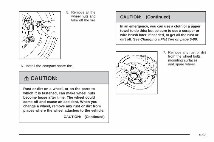
5. Remove all thewheel nuts andtake off the tire.
6. Install the compact spare tire.
{CAUTION:
Rust or dirt on a wheel, or on the parts towhich it is fastened, can make wheel nutsbecome loose after time. The wheel couldcome off and cause an accident. When youchange a wheel, remove any rust or dirt fromplaces where the wheel attaches to the vehicle.
CAUTION: (Continued)
CAUTION: (Continued)
In an emergency, you can use a cloth or a papertowel to do this; but be sure to use a scraper orwire brush later, if needed, to get all the rust ordirt off. See Changing a Flat Tire on page 5-86.
7. Remove any rust or dirtfrom the wheel bolts,mounting surfacesand spare wheel.
5-93
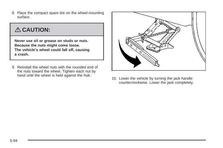
8. Place the compact spare tire on the wheel-mountingsurface.
{CAUTION:
Never use oil or grease on studs or nuts.Because the nuts might come loose.The vehicle’s wheel could fall off, causinga crash.
9. Reinstall the wheel nuts with the rounded end ofthe nuts toward the wheel. Tighten each nut byhand until the wheel is held against the hub.
10. Lower the vehicle by turning the jack handlecounterclockwise. Lower the jack completely.
5-94

{CAUTION:
Incorrect or improperly tightened wheel nutscan cause the wheel to come loose andeven come off. This could lead to a crash.If you have to replace them, be sure to getnew original equipment wheel nuts. Stopsomewhere as soon as you can and have thenuts tightened with a torque wrench to theproper torque specification. See Capacitiesand Specifications on page 5-125 for wheel nuttorque specification.
Notice: Improperly tightened wheel nuts can leadto brake pulsation and rotor damage. To avoidexpensive brake repairs, evenly tighten the wheelnuts in the proper sequence and to the propertorque specification. See Capacities andSpecifications on page 5-125 for the wheel nuttorque specification.
11. Tighten the wheel nutsfirmly in a crisscrosssequence as shown.
5-95

To change the front flat tire:
Front Tire Changing Procedure1. Perform a rear tire change by removing the rear tire
and installing the compact spare tire in the rearwheel location. The rear road tire will be usedto replace the front flat tire. See Rear Tire ChangingProcedure in this section.
2. Using the wheel wrench, loosen all the wheel nutson the front flat tire. Do not remove them yet.
3. Position the jack on the front position and raise thejack lift head to fit over the car flange under thedown arrow markings on the rocker panel.
5-96
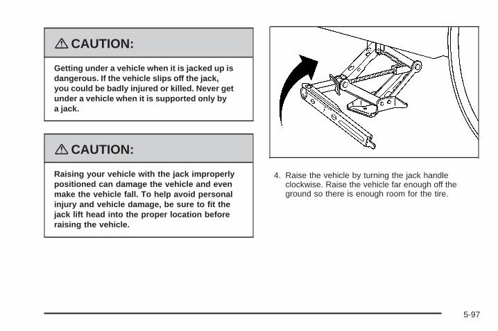
{CAUTION:
Getting under a vehicle when it is jacked up isdangerous. If the vehicle slips off the jack,you could be badly injured or killed. Never getunder a vehicle when it is supported only bya jack.
{CAUTION:
Raising your vehicle with the jack improperlypositioned can damage the vehicle and evenmake the vehicle fall. To help avoid personalinjury and vehicle damage, be sure to fit thejack lift head into the proper location beforeraising the vehicle.
4. Raise the vehicle by turning the jack handleclockwise. Raise the vehicle far enough off theground so there is enough room for the tire.
5-97

5. Remove all the wheelnuts and take off theflat tire.
6. Install the tire.
{CAUTION:
Rust or dirt on a wheel, or on the parts towhich it is fastened, can make wheel nutsbecome loose after time. The wheel couldcome off and cause an accident. When youchange a wheel, remove any rust or dirt fromplaces where the wheel attaches to the vehicle.
CAUTION: (Continued)
CAUTION: (Continued)
In an emergency, you can use a cloth or a papertowel to do this; but be sure to use a scraper orwire brush later, if needed, to get all the rust ordirt off. See Changing a Flat Tire on page 5-86.
7. Remove any rust or dirtfrom the wheel bolts,mounting surfaces,and wheel.
5-98
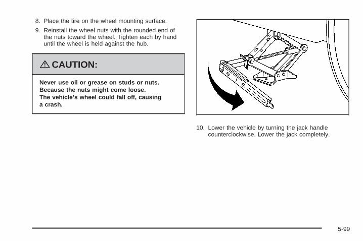
8. Place the tire on the wheel mounting surface.
9. Reinstall the wheel nuts with the rounded end ofthe nuts toward the wheel. Tighten each by handuntil the wheel is held against the hub.
{CAUTION:
Never use oil or grease on studs or nuts.Because the nuts might come loose.The vehicle’s wheel could fall off, causinga crash.
10. Lower the vehicle by turning the jack handlecounterclockwise. Lower the jack completely.
5-99
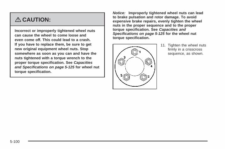
{CAUTION:
Incorrect or improperly tightened wheel nutscan cause the wheel to come loose andeven come off. This could lead to a crash.If you have to replace them, be sure to getnew original equipment wheel nuts. Stopsomewhere as soon as you can and have thenuts tightened with a torque wrench to theproper torque specification. See Capacitiesand Specifications on page 5-125 for wheel nuttorque specification.
Notice: Improperly tightened wheel nuts can leadto brake pulsation and rotor damage. To avoidexpensive brake repairs, evenly tighten the wheelnuts in the proper sequence and to the propertorque specification. See Capacities andSpecifications on page 5-125 for the wheel nuttorque specification.
11. Tighten the wheel nutsfirmly in a crisscrosssequence, as shown.
5-100
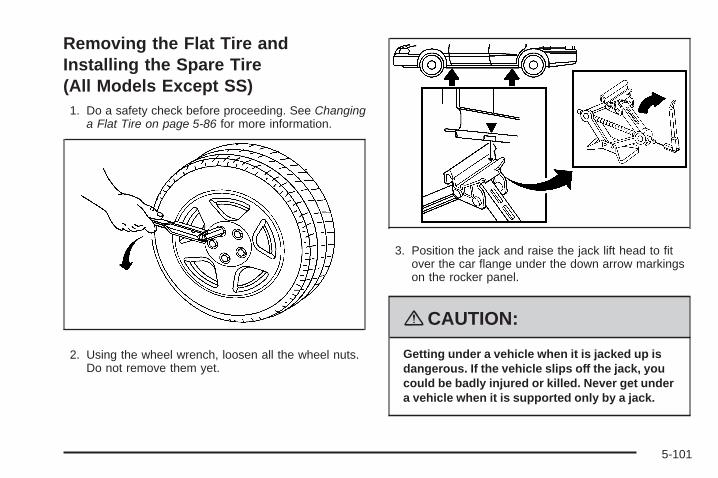
Removing the Flat Tire andInstalling the Spare Tire(All Models Except SS)1. Do a safety check before proceeding. See Changing
a Flat Tire on page 5-86 for more information.
2. Using the wheel wrench, loosen all the wheel nuts.Do not remove them yet.
3. Position the jack and raise the jack lift head to fitover the car flange under the down arrow markingson the rocker panel.
{CAUTION:
Getting under a vehicle when it is jacked up isdangerous. If the vehicle slips off the jack, youcould be badly injured or killed. Never get undera vehicle when it is supported only by a jack.
5-101

{CAUTION:
Raising your vehicle with the jack improperlypositioned can damage the vehicle and evenmake the vehicle fall. To help avoid personalinjury and vehicle damage, be sure to fit thejack lift head into the proper location beforeraising the vehicle.
4. Raise the vehicle by turning the jack handleclockwise. Raise the vehicle far enough off theground so there is enough room for the compactspare tire to fit underneath the wheel well.
5-102

5. Remove all the wheelnuts and take off theflat tire.
{CAUTION:
Rust or dirt on a wheel, or on the parts towhich it is fastened, can make wheel nutsbecome loose after time. The wheel couldcome off and cause an accident. When youchange a wheel, remove any rust or dirt fromplaces where the wheel attaches to the vehicle.
CAUTION: (Continued)
CAUTION: (Continued)
In an emergency, you can use a cloth or a papertowel to do this; but be sure to use a scraper orwire brush later, if needed, to get all the rust ordirt off. See Changing a Flat Tire on page 5-86.
6. Remove any rust or dirtfrom the wheel bolts,mounting surfacesand spare wheel.
5-103

7. Place the compact spare tire on the wheel-mountingsurface.
{CAUTION:
Never use oil or grease on studs or nuts.Because the nuts might come loose.The vehicle’s wheel could fall off, causinga crash.
8. Reinstall the wheel nuts with the rounded end ofthe nuts toward the wheel. Tighten each nut byhand until the wheel is held against the hub.
9. Lower the vehicle by turning the jack handlecounterclockwise. Lower the jack completely.
5-104

{CAUTION:
Incorrect or improperly tightened wheel nutscan cause the wheel to come loose andeven come off. This could lead to a crash.If you have to replace them, be sure to getnew original equipment wheel nuts. Stopsomewhere as soon as you can and have thenuts tightened with a torque wrench to theproper torque specification. See Capacitiesand Specifications on page 5-125 for wheel nuttorque specification.
Notice: Improperly tightened wheel nuts can leadto brake pulsation and rotor damage. To avoidexpensive brake repairs, evenly tighten the wheelnuts in the proper sequence and to the propertorque specification. See Capacities andSpecifications on page 5-125 for the wheel nuttorque specification.
10. Tighten the wheel nutsfirmly in a crisscrosssequence as shown.
5-105
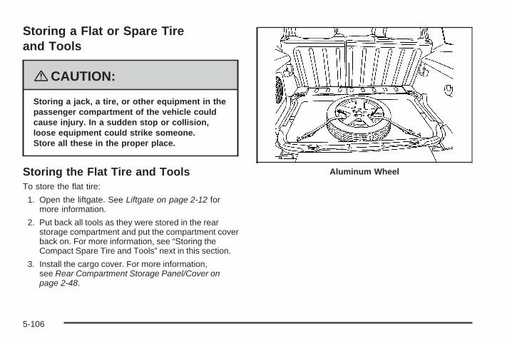
Storing a Flat or Spare Tireand Tools
{CAUTION:
Storing a jack, a tire, or other equipment in thepassenger compartment of the vehicle couldcause injury. In a sudden stop or collision,loose equipment could strike someone.Store all these in the proper place.
Storing the Flat Tire and ToolsTo store the flat tire:
1. Open the liftgate. See Liftgate on page 2-12 formore information.
2. Put back all tools as they were stored in the rearstorage compartment and put the compartment coverback on. For more information, see “Storing theCompact Spare Tire and Tools” next in this section.
3. Install the cargo cover. For more information,see Rear Compartment Storage Panel/Cover onpage 2-48.
Aluminum Wheel
5-106

4. Route the tie-down strap through the tire as shownin the graphic
5. Attach the strap to thecargo tie-downs in therear of the vehicle.
6. Tighten the tie-down strap.
Steel Wheel
5-107

Storing the Compact Spare Tireand ToolsUse the diagram as a guide for storing the compactspare tire once you are done using it.
A. RetainerB. CoverC. Spare TireD. Wing Nut
E. Jack and WheelWrench
F. StrapG. Bolt
1. Open the liftgate. See Liftgate on page 2-12 formore information.
2. Install the strap (F) on the floor of the spare tirecompartment.
3. Place the jack and wheel wrench (E) over thebolt (G), making sure the strap is securelystored, under the jack and wheel wrench.
4. Secure the jack and wheel wrench (E) with thewing nut (D).
5. With the valve stem up, place the spare tire (C) onthe compartment floor.
6. Make sure the bolt (G) passes through the wheelcenter.
7. Install the spare tire cover (B).
8. Secure the spare tire and tools with the retainer (A).
The compact spare tire storage area is designed onlyfor the compact spare tire, the standard tire cannotbe stored there.
5-108
Compact Spare TireAlthough the compact spare tire was fully inflatedwhen the vehicle was new, it can lose air after a time.Check the inflation pressure regularly. It should be60 psi (420 kPa).
After installing the compact spare on the vehicle, stopas soon as possible and make sure the spare tireis correctly inflated. The compact spare is made toperform well at speeds up to 65 mph (105 km/h)for distances up to 3,000 miles (5 000 km), so you canfinish your trip and have the full-size tire repaired orreplaced at your convenience. Of course, it is bestto replace the spare with a full-size tire as soon aspossible. The spare tire will last longer and be in goodshape in case it is needed again.
Notice: When the compact spare is installed,do not take your vehicle through an automaticcar wash with guide rails. The compact spare canget caught on the rails. That can damage the tire andwheel, and maybe other parts of your vehicle.
Do not use the compact spare on other vehicles.
And do not mix the compact spare tire or wheel withother wheels or tires. They will not fit. Keep thespare tire and its wheel together.
Notice: Tire chains will not fit your compact spare.Using them can damage your vehicle and candamage the chains too. Do not use tire chains onyour compact spare.
5-109

Appearance Care
Interior CleaningYour vehicle’s interior will continue to look its best if it iscleaned often. Although not always visible, dust anddirt can accumulate on your upholstery. Dirt can damagecarpet, fabric, leather, and plastic surfaces. Regularvacuuming is recommended to remove particlesfrom your upholstery. It is important to keep yourupholstery from becoming and remaining heavily soiled.Soils should be removed as quickly as possible.Your vehicle’s interior may experience extremes ofheat that could cause stains to set rapidly.
Lighter colored interiors may require more frequentcleaning. Use care because newspapers and garmentsthat transfer color to your home furnishings may alsotransfer color to your vehicle’s interior.
When cleaning your vehicle’s interior, only use cleanersspecifically designed for the surfaces being cleaned.Permanent damage may result from using cleaners onsurfaces for which they were not intended. Use glasscleaner only on glass. Remove any accidental over-sprayfrom other surfaces immediately. To prevent over-spray,apply cleaner directly to the cleaning cloth.
Notice: If you use abrasive cleaners when cleaningglass surfaces on your vehicle, you could scratchthe glass and/or cause damage to the rear windowdefogger. When cleaning the glass on yourvehicle, use only a soft cloth and glass cleaner.
Many cleaners contain solvents that may becomeconcentrated in your vehicle’s breathing space.Before using cleaners, read and adhere to all safetyinstructions on the label. While cleaning your vehicle’sinterior, maintain adequate ventilation by openingyour vehicle’s doors and windows.
Dust may be removed from small buttons and knobsusing a small brush with soft bristles.
Your dealer/retailer has a product for cleaning yourvehicle’s glass. Should it become necessary, you canalso obtain a product from your dealer/retailer to removeodors from your vehicle’s upholstery.
5-110

Do not clean your vehicle using the following cleanersor techniques:
• Never use a knife or any other sharp object toremove a soil from any interior surface.
• Never use a stiff brush. It can cause damage toyour vehicle’s interior surfaces.
• Never apply heavy pressure or rub aggressivelywith a cleaning cloth. Use of heavy pressurecan damage your interior and does not improve theeffectiveness of soil removal.
• Use only mild, neutral-pH soaps. Avoid laundrydetergents or dishwashing soaps with degreasers.Using too much soap will leave a residue thatleaves streaks and attracts dirt. For liquid cleaners,about 20 drops per gallon (3.78 L) of water is agood guide.
• Do not heavily saturate your upholstery whilecleaning.
• Damage to your vehicle’s interior may result fromthe use of many organic solvents such as naptha,alcohol, etc.
Fabric/CarpetUse a vacuum cleaner with a soft brush attachmentfrequently to remove dust and loose dirt. A canistervacuum with a beater bar in the nozzle may only be usedon floor carpet and carpeted floor mats. For soils, alwaystry to remove them first with plain water or club soda.Before cleaning, gently remove as much of the soil aspossible using one of the following techniques:• For liquids: gently blot the remaining soil with a paper
towel. Allow the soil to absorb into the paper toweluntil no more can be removed.
• For solid dry soils: remove as much as possible andthen vacuum.
To clean, use the following instructions:1. Saturate a lint-free, clean white cloth with water or
club soda.2. Wring the cloth to remove excess moisture.3. Start on the outside edge of the soil and gently rub
toward the center. Continue cleaning, using a cleanarea of the cloth each time it becomes soiled.
4. Continue to gently rub the soiled area until thecleaning cloth remains clean.
5. If the soil is not completely removed, use a mildsoap solution and repeat the cleaning processthat was used with plain water.
5-111
If any of the soil remains, a commercial fabric cleaner orspot lifter may be necessary. When a commercialupholstery cleaner or spot lifter is to be used, test asmall hidden area for colorfastness first. If the locallycleaned area gives any impression that a ring formationmay result, clean the entire surface.
After the cleaning process has been completed, a papertowel can be used to blot excess moisture from thefabric or carpet.
Instrument Panel, Vinyl, and OtherPlastic SurfacesA soft cloth dampened with water may be used toremove dust. If a more thorough cleaning isnecessary, a clean soft cloth dampened with a mildsoap solution can be used to gently remove dust anddirt. Never use spot lifters or removers on plasticsurfaces. Many commercial cleaners and coatings thatare sold to preserve and protect soft plastic surfacesmay permanently change the appearance and feelof your interior and are not recommended. Do not usesilicone or wax-based products, or those containingorganic solvents to clean your vehicle’s interior becausethey can alter the appearance by increasing the glossin a non-uniform manner.
Some commercial products may increase gloss on yourinstrument panel. The increase in gloss may causeannoying reflections in the windshield and even make itdifficult to see through the windshield under certainconditions.
Care of Safety BeltsKeep belts clean and dry.
{CAUTION:
Do not bleach or dye safety belts. If you do,it may severely weaken them. In a crash,they might not be able to provide adequateprotection. Clean safety belts only with mildsoap and lukewarm water.
5-112

WeatherstripsSilicone grease on weatherstrips will make them lastlonger, seal better, and not stick or squeak. Applysilicone grease with a clean cloth. During very cold,damp weather frequent application may be required.See Recommended Fluids and Lubricants on page 6-12.
Washing Your VehicleThe best way to preserve your vehicle’s finish is to keepit clean by washing it often.
Notice: Certain cleaners contain chemicals that candamage the emblems or nameplates on yourvehicle. Check the cleaning product label. If it statesthat it should not be used on plastic parts, do notuse it on your vehicle or damage may occurand it would not be covered by the warranty.
Do not wash the vehicle in direct sunlight. Use a carwashing soap. Do not use cleaning agents thatare petroleum based or that contain acid or abrasives,as they can damage the paint, metal or plastic onyour vehicle. Approved cleaning products can beobtained from your dealer/retailer. See VehicleCare/Appearance Materials on page 5-117.
Follow all manufacturers’ directions regarding correctproduct usage, necessary safety precautions andappropriate disposal of any vehicle care product.
Rinse the vehicle well, before washing and after toremove all cleaning agents completely. If they areallowed to dry on the surface, they could stain.
Dry the finish with a soft, clean chamois or an all-cottontowel to avoid surface scratches and water spotting
High pressure car washes may cause water to enter thevehicle. Avoid using high pressure washes closerthan 12 inches (30 cm) to the surface of the vehicle.Use of power washers exceeding 1,200 psi (8 274 kPa)can result in damage or removal of paint and decals.
Cleaning Exterior Lamps/LensesUse only lukewarm or cold water, a soft cloth and acar washing soap to clean exterior lamps and lenses.Follow instructions under Washing Your Vehicle onpage 5-113.
5-113

Finish CareOccasional waxing or mild polishing of your vehicle byhand may be necessary to remove residue from thepaint finish. You can get approved cleaning productsfrom your dealer/retailer. See Vehicle Care/AppearanceMaterials on page 5-117.
If your vehicle has a basecoat/clearcoat paint finish,the clearcoat gives more depth and gloss to thecolored basecoat. Always use waxes and polishes thatare non-abrasive and made for a basecoat/clearcoatpaint finish.
Notice: Machine compounding or aggressivepolishing on a basecoat/clearcoat paint finish maydamage it. Use only non-abrasive waxes andpolishes that are made for a basecoat/clearcoatpaint finish on your vehicle.
Foreign materials such as calcium chloride and othersalts, ice melting agents, road oil and tar, tree sap, birddroppings, chemicals from industrial chimneys, etc.,can damage your vehicle’s finish if they remain onpainted surfaces. Wash the vehicle as soon as possible.If necessary, use non-abrasive cleaners that are markedsafe for painted surfaces to remove foreign matter.Exterior painted surfaces are subject to aging, weatherand chemical fallout that can take their toll over aperiod of years. You can help to keep the paint finishlooking new by keeping your vehicle garaged or coveredwhenever possible.
Protecting Exterior Bright Metal PartsBright metal parts should be cleaned regularly to keeptheir luster. Washing with water is all that is usuallyneeded. However, you may use chrome polish onchrome or stainless steel trim, if necessary.
Use special care with aluminum trim. To avoid damagingprotective trim, never use auto or chrome polish,steam or caustic soap to clean aluminum. A coating ofwax, rubbed to high polish, is recommended for allbright metal parts.
Windshield and Wiper BladesClean the outside of the windshield with glass cleaner.
Clean the rubber blades using a lint free cloth orpaper towel soaked with windshield washer fluid or amild detergent. Wash the windshield thoroughlywhen cleaning the blades. Bugs, road grime, sap, and abuildup of vehicle wash/wax treatments may causewiper streaking. Replace the wiper blades if they areworn or damaged.
Wipers can be damaged by:
• Extreme dusty conditions
• Sand and salt
• Heat and sun
• Snow and ice, without proper removal
5-114

Aluminum or Chrome-Plated Wheelsand TrimYour vehicle may have either aluminum orchrome-plated wheels.
Keep the wheels clean using a soft clean cloth with mildsoap and water. Rinse with clean water. After rinsingthoroughly, dry with a soft clean towel. A wax may thenbe applied.
Notice: Chrome wheels and other chrome trim maybe damaged if you do not wash your vehicle afterdriving on roads that have been sprayed withmagnesium, calcium or sodium chloride. Thesechlorides are used on roads for conditions such asice and dust. Always wash your vehicle’s chromewith soap and water after exposure.
Notice: If you use strong soaps, chemicals,abrasive polishes, cleaners, brushes, or cleanersthat contain acid on aluminum or chrome-platedwheels, you could damage the surface of thewheel(s). The repairs would not be covered by yourwarranty. Use only approved cleaners on aluminumor chrome-plated wheels.
The surface of these wheels is similar to the paintedsurface of your vehicle. Do not use strong soaps,chemicals, abrasive polishes, abrasive cleaners,cleaners with acid, or abrasive cleaning brushes onthem because you could damage the surface. Do notuse chrome polish on aluminum wheels.
Notice: Using chrome polish on aluminum wheelscould damage the wheels. The repairs would notbe covered by your warranty. Use chrome polish onchrome wheels only.
Use chrome polish only on chrome-plated wheels, butavoid any painted surface of the wheel, and buff offimmediately after application.
Notice: If you drive your vehicle through anautomatic car wash that has silicone carbide tirecleaning brushes, you could damage the aluminumor chrome-plated wheels. The repairs would notbe covered by your warranty. Never drive a vehicleequipped with aluminum or chrome-plated wheelsthrough an automatic car wash that uses siliconecarbide tire cleaning brushes.
5-115

TiresTo clean the tires, use a stiff brush with tire cleaner.
Notice: Using petroleum-based tire dressingproducts on your vehicle may damage the paintfinish and/or tires. When applying a tire dressing,always wipe off any overspray from all paintedsurfaces on your vehicle.
Sheet Metal DamageIf the vehicle is damaged and requires sheet metalrepair or replacement, make sure the body repair shopapplies anti-corrosion material to parts repaired orreplaced to restore corrosion protection.
Original manufacturer replacement parts will provide thecorrosion protection while maintaining the warranty.
Finish DamageAny stone chips, fractures or deep scratches in the finishshould be repaired right away. Bare metal will corrodequickly and may develop into major repair expense.
Minor chips and scratches can be repaired with touch-upmaterials available from your dealer/retailer. Largerareas of finish damage can be corrected in yourdealer’s/retailer’s body and paint shop.
Underbody MaintenanceChemicals used for ice and snow removal and dustcontrol can collect on the underbody. If these are notremoved, corrosion and rust can develop on theunderbody parts such as fuel lines, frame, floor pan,and exhaust system even though they have corrosionprotection.
At least every spring, flush these materials from theunderbody with plain water. Clean any areas where mudand debris can collect. Dirt packed in close areas ofthe frame should be loosened before being flushed.Your dealer/retailer or an underbody car washing systemcan do this for you.
Chemical Paint SpottingSome weather and atmospheric conditions can create achemical fallout. Airborne pollutants can fall upon andattack painted surfaces on the vehicle. This damage cantake two forms: blotchy, ring-shaped discolorations, andsmall, irregular dark spots etched into the paint surface.
Although no defect in the paint job causes this, we willrepair, at no charge to the owner, the surfaces ofnew vehicles damaged by this fallout condition within12 months or 12,000 miles (20 000 km) of purchase,whichever occurs first.
5-116
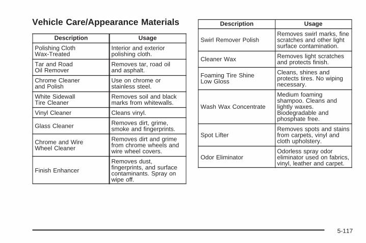
Vehicle Care/Appearance Materials
Description Usage
Polishing ClothWax-Treated
Interior and exteriorpolishing cloth.
Tar and RoadOil Remover
Removes tar, road oiland asphalt.
Chrome Cleanerand Polish
Use on chrome orstainless steel.
White SidewallTire Cleaner
Removes soil and blackmarks from whitewalls.
Vinyl Cleaner Cleans vinyl.
Glass Cleaner Removes dirt, grime,smoke and fingerprints.
Chrome and WireWheel Cleaner
Removes dirt and grimefrom chrome wheels andwire wheel covers.
Finish Enhancer
Removes dust,fingerprints, and surfacecontaminants. Spray onwipe off.
Description Usage
Swirl Remover PolishRemoves swirl marks, finescratches and other lightsurface contamination.
Cleaner Wax Removes light scratchesand protects finish.
Foaming Tire ShineLow Gloss
Cleans, shines andprotects tires. No wipingnecessary.
Wash Wax Concentrate
Medium foamingshampoo. Cleans andlightly waxes.Biodegradable andphosphate free.
Spot LifterRemoves spots and stainsfrom carpets, vinyl andcloth upholstery.
Odor EliminatorOdorless spray odoreliminator used on fabrics,vinyl, leather and carpet.
5-117
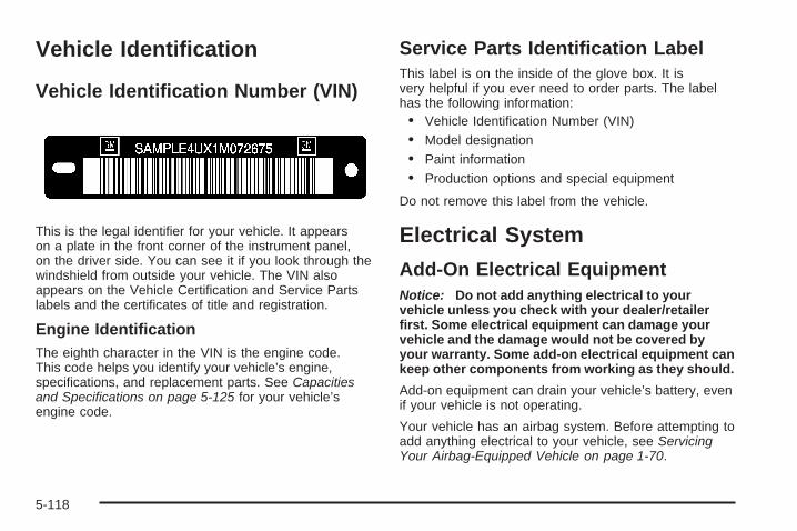
Vehicle Identification
Vehicle Identification Number (VIN)
This is the legal identifier for your vehicle. It appearson a plate in the front corner of the instrument panel,on the driver side. You can see it if you look through thewindshield from outside your vehicle. The VIN alsoappears on the Vehicle Certification and Service Partslabels and the certificates of title and registration.
Engine IdentificationThe eighth character in the VIN is the engine code.This code helps you identify your vehicle’s engine,specifications, and replacement parts. See Capacitiesand Specifications on page 5-125 for your vehicle’sengine code.
Service Parts Identification LabelThis label is on the inside of the glove box. It isvery helpful if you ever need to order parts. The labelhas the following information:• Vehicle Identification Number (VIN)• Model designation• Paint information• Production options and special equipment
Do not remove this label from the vehicle.
Electrical System
Add-On Electrical EquipmentNotice: Do not add anything electrical to yourvehicle unless you check with your dealer/retailerfirst. Some electrical equipment can damage yourvehicle and the damage would not be covered byyour warranty. Some add-on electrical equipment cankeep other components from working as they should.
Add-on equipment can drain your vehicle’s battery, evenif your vehicle is not operating.
Your vehicle has an airbag system. Before attempting toadd anything electrical to your vehicle, see ServicingYour Airbag-Equipped Vehicle on page 1-70.
5-118
Headlamp WiringThe headlamp wiring is protected by fuses in the fuseblock. An electrical overload will cause the lamps to turnoff. If this happens, have your headlamp wiring checkedright away.
Windshield Wiper FusesThe windshield wiper motor is protected by a circuitbreaker and a fuse. If the motor overheats due to heavysnow, etc., the wiper will stop until the motor cools.If the overload is caused by some electrical problem,have it fixed.
Power Windows and Other PowerOptionsFuses in the fuse block protect the power windows.When the current load is too heavy, the fuse opensprotecting the circuit until the problem is fixed.
Fuses and Circuit BreakersThe wiring circuits in your vehicle are protected fromshort circuits by a combination of fuses, circuit breakersand fusible thermal links. This greatly reduces thechance of damage caused by electrical problems.
Look at the silver-colored band inside the fuse. If theband is broken or melted, replace the fuse. Be sure youreplace a bad fuse with a new one of the identicalsize and rating.
If you ever have a problem on the road and do not havea spare fuse, you can “borrow” one that has the sameamperage. Just pick some feature of your vehiclethat you can get along without — like the radio orcigarette lighter — and use its fuse if it is the correctamperage. Replace it as soon as you can.
There are two fuse blocks in your vehicle: the floorconsole fuse block and the engine compartmentfuse block.
There are also one or two fuses located at the back ofthe vehicle near the battery.
5-119

Floor Console Fuse Block
The floor console fuse block is located on the passengerside of the floor console behind the forward panel.The panel has four clips, one in each corner. Pull thepanel to disconnect the four clips, and access the fuses.Use the fuse puller to remove fuses.
5-120
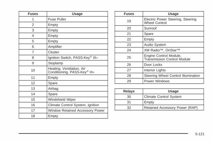
Fuses Usage
1 Fuse Puller
2 Empty
3 Empty
4 Empty
5 Empty
6 Amplifier
7 Cluster
8 Ignition Switch, PASS-Key® III+9 Stoplamp
10 Heating, Ventilation, AirConditioning, PASS-Key® III+
11 Empty
12 Spare
13 Airbag
14 Spare
15 Windshield Wiper
16 Climate Control System, Ignition
17 Window Retained Accessory Power
18 Empty
Fuses Usage
19 Electric Power Steering, SteeringWheel Control
20 Sunroof
21 Spare
22 Empty
23 Audio System
24 XM Radio™, OnStar™
25 Engine Control Module,Transmission Control Module
26 Door Locks
27 Interior Lights
28 Steering Wheel Control Illumination
29 Power Windows
Relays Usage
30 Climate Control System
31 Empty
32 Retained Accessory Power (RAP)
5-121

Engine Compartment Fuse BlockThe underhood fuse block is located on the driver sideof the engine compartment. Lift the cover to accessthe fuse/relay block.
Notice: Spilling liquid on any electrical componentson your vehicle may damage it. Always keep thecovers on any electrical component.
Fuses Usage
1 Electric Power Steering
2 Rear Defogger
3 Empty
4 Body Control Module 3
5 Starting System
6 Body Control Module 2
7 Rear Power Plug (Panel Van Only),Cooling Fan (SS only)
8 Empty
9 Air Conditioning Clutch Diode
10 Liftgate, Sunroof
11 Empty
12 Rear Power Outlet (Panel Van Only)
13 Fuel Pump
20 Rear Wiper
21 Mirror
22 Air Conditioning
23 Heated Seats (Option)
5-122

Fuses Usage
25 Fuse Puller
27 Empty
29 Cigarette Lighter
30 Power Outlet
31 Daytime Running Lamps
32 Empty
33 Emissions
36 Power Windows (Turbo Only)
37 Power Seat (Option)
40 Cooling Fan
41 Engine Control Module
42 Cam Phaser (Turbo Only)
43 Engine Control Module,Transmission
44 Antilock Brake System (Option)
45 Injectors, Ignition Module
46 Backup Lamps
Fuses Usage
47 Heated Seat (Option)
49 Windshield Washer Pump
53 Fog Lamps (Option)
56 Sensing and DiagnosticModule (SDM)
57 Antilock Brake System (Option)
58 Windshield Wiper Diode
59 Windshield Wiper
60 Horn
61 Antilock Brake System (Option)
62 Instrument Panel, Ignition
63 Driver Side High-Beam
64 Canister Vent
65 Driver Side Low-Beam
66 Passenger Side Low-Beam
67 Passenger Side High-Beam
69 Parking Lamps
5-123
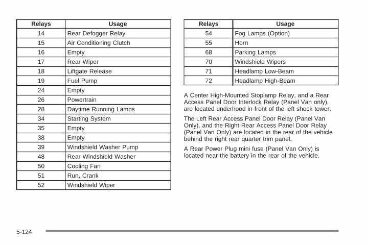
Relays Usage
14 Rear Defogger Relay
15 Air Conditioning Clutch
16 Empty
17 Rear Wiper
18 Liftgate Release
19 Fuel Pump
24 Empty
26 Powertrain
28 Daytime Running Lamps
34 Starting System
35 Empty
38 Empty
39 Windshield Washer Pump
48 Rear Windshield Washer
50 Cooling Fan
51 Run, Crank
52 Windshield Wiper
Relays Usage
54 Fog Lamps (Option)
55 Horn
68 Parking Lamps
70 Windshield Wipers
71 Headlamp Low-Beam
72 Headlamp High-Beam
A Center High-Mounted Stoplamp Relay, and a RearAccess Panel Door Interlock Relay (Panel Van only),are located underhood in front of the left shock tower.
The Left Rear Access Panel Door Relay (Panel VanOnly), and the Right Rear Access Panel Door Relay(Panel Van Only) are located in the rear of the vehiclebehind the right rear quarter trim panel.
A Rear Power Plug mini fuse (Panel Van Only) islocated near the battery in the rear of the vehicle.
5-124

Capacities and SpecificationsThe following approximate capacities are given in English and metric conversions. Please refer to MaintenanceReplacement Parts on page 6-14 for more information.
ApplicationCapacities
English Metric
Air Conditioning Refrigerant R134aFor the air conditioning system refrigerant charge
amount, see the refrigerant caution label located underthe hood. See your dealer/retailer for more information.
Cooling System
2.0L Engine 9.2 qt 8.7 L
2.2L Engine 7.4 qt 7.0 L
2.4L Engine Manual 8.7 qt 8.2 L
2.4L Engine Automatic 8.5 qt 8.0 L
Engine Oil with Filter 5.0 qt 4.7 L
Fuel Tank 16.2 gal 61.3 L
Transaxle, Automatic (Complete Drain and Refill) 6.9 qt 6.5 L
Transaxle, Manual with 2.0L Engine(Complete Drain and Refill) 2.0 qt 1.9 L
Transaxle, Manual with 2.2L or 2.4L Engine(Complete Drain and Refill) 1.7 qt 1.6 L
Wheel Nut Torque 100 lb ft 140 Y
All capacities are approximate. When adding, be sure to fill to the appropriate level, as recommended in thismanual.
5-125

Engine SpecificationsEngine VIN Code Transaxle Spark Plug Gap
2.0L L4 X AutomaticManual 0.035 in (0.90 mm)
2.2L L4 D AutomaticManual 0.040 in (1.01 mm)
2.4L L4 P AutomaticManual 0.040 in (1.01 mm)
5-126

Maintenance Schedule .....................................6-2Introduction ...................................................6-2Maintenance Requirements ..............................6-2Your Vehicle and the Environment ....................6-2Using the Maintenance Schedule ......................6-2Scheduled Maintenance ...................................6-4Additional Required Services ............................6-6Maintenance Footnotes ...................................6-7
Owner Checks and Services ............................6-8At Each Fuel Fill ............................................6-8At Least Once a Month ...................................6-9At Least Once a Year .....................................6-9Recommended Fluids and Lubricants ...............6-12Maintenance Replacement Parts .....................6-14Engine Drive Belt Routing ..............................6-15Maintenance Record .....................................6-16
Section 6 Maintenance Schedule
6-1

Maintenance Schedule
IntroductionImportant: Keep engine oil at the proper level andchange as recommended.
Have you purchased the GM Protection Plan? The Plansupplements your new vehicle warranties. See yourWarranty and Owner Assistance booklet or yourdealer/retailer for details.
Maintenance RequirementsNotice: Maintenance intervals, checks, inspections,replacement parts, and recommended fluids andlubricants as prescribed in this manual arenecessary to keep your vehicle in good workingcondition. Any damage caused by failure to followscheduled maintenance might not be coveredby warranty.
Your Vehicle and the EnvironmentProper vehicle maintenance not only helps to keep yourvehicle in good working condition, but also helps theenvironment. All recommended maintenance isimportant. Improper vehicle maintenance can evenaffect the quality of the air we breathe. Improper fluidlevels or the wrong tire inflation can increase the level ofemissions from your vehicle. To help protect ourenvironment, and to keep your vehicle in good condition,be sure to maintain your vehicle properly.
Using the Maintenance ScheduleWe want to help you keep your vehicle in good workingcondition. But we do not know exactly how you willdrive it. You might drive very short distances only a fewtimes a week. Or you might drive long distances allthe time in very hot, dusty weather. You might use yourvehicle in making deliveries. Or you might drive it towork, to do errands, or in many other ways.
Because of all the different ways people use theirvehicles, maintenance needs vary. You might need morefrequent checks and replacements. So please readthe following and note how you drive. If you have anyquestions on how to keep your vehicle in good condition,see your dealer/retailer.
6-2

This schedule is for vehicles that:
• carry passengers and cargo within recommendedlimits. You will find these limits on the Tire andLoading Information label. See Loading YourVehicle on page 4-27.
• are driven on reasonable road surfaces within legaldriving limits.
• use the recommended fuel. See Gasoline Octaneon page 5-5.
The services in Scheduled Maintenance on page 6-4should be performed when indicated. See AdditionalRequired Services on page 6-6 and MaintenanceFootnotes on page 6-7 for further information.
{CAUTION:
Performing maintenance work on a vehicle canbe dangerous. In trying to do some jobs, youcan be seriously injured. Do your ownmaintenance work only if you have therequired know-how and the proper tools andequipment for the job.
CAUTION: (Continued)
CAUTION: (Continued)
If you have any doubt, see your dealer/retailerto have a qualified technician do the work. SeeDoing Your Own Service Work on page 5-4.
Some maintenance services can be complex. So,unless you are technically qualified and have thenecessary equipment, you should have yourdealer/retailer do these jobs.
When you go to your dealer/retailer for your serviceneeds, you will know that trained and supported servicetechnicians will perform the work using genuine parts.
If you want to purchase service information, see ServicePublications Ordering Information on page 7-15.
Owner Checks and Services on page 6-8 tells you whatshould be checked, when to check it, and what you caneasily do to help keep your vehicle in good condition.
The proper replacement parts, fluids, and lubricants touse are listed in Recommended Fluids and Lubricantson page 6-12 and Maintenance Replacement Partson page 6-14. When your vehicle is serviced, make surethese are used. All parts should be replaced and allnecessary repairs done before you or anyone elsedrives the vehicle. We recommend the use of genuineparts from your dealer/retailer.
6-3

Scheduled MaintenanceWhen the CHANGE OIL SOON message comes on, itmeans that service is required for your vehicle. Haveyour vehicle serviced as soon as possible within the next600 miles (1 000 km). It is possible that, if you aredriving under the best conditions, the engine oillife system may not indicate that vehicle service isnecessary for over a year. However, your engine oil andfilter must be changed at least once a year and atthis time the system must be reset. Your dealer/retailerhas trained service technicians who will perform thiswork using genuine parts and reset the system.
If the engine oil life system is ever reset accidentally,you must service your vehicle within 3,000 miles(5 000 km) since your last service. Remember to resetthe oil life system whenever the oil is changed. SeeEngine Oil Life System on page 5-19 for information onthe Engine Oil Life System and resetting the system.
When the CHANGE OIL SOON message appears,certain services, checks, and inspections are required.Required services are described in the following for“Maintenance I” and “Maintenance II.” Generally,it is recommended that your first service beMaintenance I, your second service be Maintenance II,and that you alternate Maintenance I and Maintenance IIthereafter. However, in some cases, Maintenance IImay be required more often.
Maintenance I — Use Maintenance I if the CHANGEOIL SOON message comes on within 10 monthssince the vehicle was purchased or Maintenance II wasperformed.
Maintenance II — Use Maintenance II if the previousservice performed was Maintenance I. Always useMaintenance II whenever the CHANGE OIL SOONmessage comes on 10 months or more since the lastservice or if the message has not come on at all forone year.
6-4
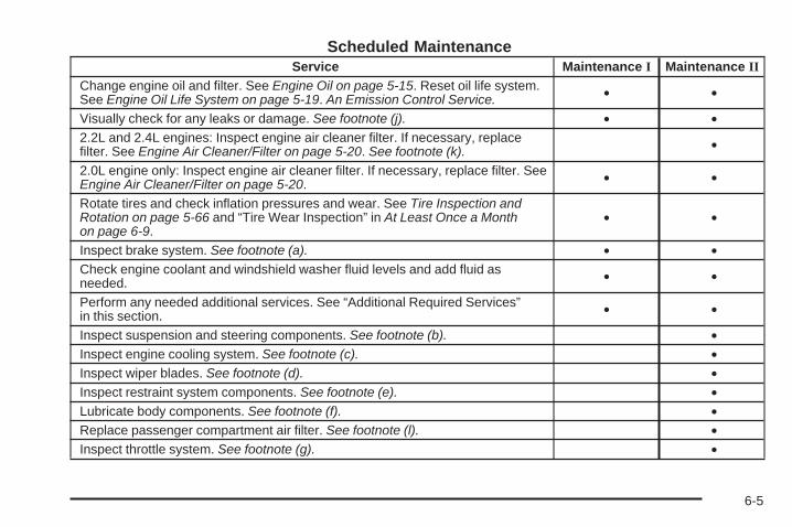
Scheduled MaintenanceService Maintenance I Maintenance II
Change engine oil and filter. See Engine Oil on page 5-15. Reset oil life system.See Engine Oil Life System on page 5-19. An Emission Control Service. • •
Visually check for any leaks or damage. See footnote (j). • •2.2L and 2.4L engines: Inspect engine air cleaner filter. If necessary, replacefilter. See Engine Air Cleaner/Filter on page 5-20. See footnote (k). •
2.0L engine only: Inspect engine air cleaner filter. If necessary, replace filter. SeeEngine Air Cleaner/Filter on page 5-20. • •
Rotate tires and check inflation pressures and wear. See Tire Inspection andRotation on page 5-66 and “Tire Wear Inspection” in At Least Once a Monthon page 6-9.
• •
Inspect brake system. See footnote (a). • •Check engine coolant and windshield washer fluid levels and add fluid asneeded. • •
Perform any needed additional services. See “Additional Required Services”in this section. • •
Inspect suspension and steering components. See footnote (b). •Inspect engine cooling system. See footnote (c). •Inspect wiper blades. See footnote (d). •Inspect restraint system components. See footnote (e). •Lubricate body components. See footnote (f). •Replace passenger compartment air filter. See footnote (l). •Inspect throttle system. See footnote (g). •
6-5

Additional Required ServicesThe following services should be performed at the first maintenance service (I or II) after the indicated miles(kilometers) shown for each item.
Additional Required Services
Service and Miles (Kilometers) 25,000(40 000)
50,000(80 000)
75,000(120 000)
100,000(160 000)
125,000(200 000)
150,000(240 000)
Inspect fuel system for damage or leaks. • • • • • •Inspect exhaust system for loose ordamaged components. • • • • • •
Replace engine air cleaner filter. SeeEngine Air Cleaner/Filter on page 5-20. • • •
Change automatic transmission fluid andfilter (severe service only). Seefootnote (h).
• • •
Replace spark plugs. An EmissionControl Service. •
Engine cooling system service (or everyfive years, whichever occurs first). AnEmission Control Service. Seefootnote (i).
•
Inspect engine accessory drive belt. AnEmission Control Service. Seefootnote (m).
•
6-6
Maintenance Footnotes(a) Visually inspect brake lines and hoses for properhook-up, binding, leaks, cracks, chafing, etc. Inspectdisc brake pads for wear and rotors for surfacecondition. Inspect drum brake linings/shoes for wearor cracks. Inspect other brake parts, including drums,wheel cylinders, calipers, parking brake, etc.
(b) Visually inspect front and rear suspension andsteering system for damaged, loose, or missing partsor signs of wear. Inspect power steering cables forproper hook-up, binding, cracks, chafing, etc.
(c) Visually inspect hoses and have them replaced ifthey are cracked, swollen, or deteriorated. Inspectall pipes, fittings, and clamps; replace with genuineparts as needed. To help ensure proper operation,a pressure test of the cooling system and pressurecap and cleaning the outside of the radiator andair conditioning condenser is recommended at leastonce a year.
(d) Inspect wiper blades for wear, cracking, orcontamination. Clean the windshield and wiper blades,if contaminated. Replace wiper blades that are wornor damaged. See Windshield Wiper Blade Replacementon page 5-50 and Windshield and Wiper Blades onpage 5-114 for more information.
(e) Make sure the safety belt reminder light and safetybelt assemblies are working properly. Look for anyother loose or damaged safety belt system parts. If yousee anything that might keep a safety belt systemfrom doing its job, have it repaired. Have any torn orfrayed safety belts replaced. Also see Checkingthe Restraint Systems on page 1-72.
(f) Lubricate all key lock cylinders, door hinges andlatches, hood hinges and latches, and trunk lid hingesand latches. More frequent lubrication may be requiredwhen exposed to a corrosive environment. Applyingsilicone grease on weatherstrips with a clean cloth willmake them last longer, seal better, and not stick orsqueak.
(g) Check system for interference or binding and fordamaged or missing parts. Replace parts as needed.Replace any components that have high effort orexcessive wear. Do not lubricate accelerator or cruisecontrol cables.
6-7
(h) Change automatic transmission fluid and filter if thevehicle is mainly driven under one or more of theseconditions:
− In heavy city traffic where the outside temperatureregularly reaches 90°F (32°C) or higher.
− In hilly or mountainous terrain.− When doing frequent trailer towing.− Uses such as found in taxi, police, or delivery
service.
If you do not use your vehicle under any of theseconditions, the fluid and filter do not require changing.
(i) Drain, flush, and refill cooling system. This servicecan be complex; you should have your dealer/retailerperform this service. See Engine Coolant on page 5-24for what to use. Inspect hoses. Clean radiator,condenser, pressure cap, and filler neck. Pressure testthe cooling system and pressure cap.
(j) A fluid loss in any vehicle system could indicate aproblem. Have the system inspected and repaired andthe fluid level checked. Add fluid if needed.
(k) If you drive regularly under dusty conditions, inspectthe filter at each engine oil change.
(l) If you drive regularly under dusty conditions, the filtermay require replacement more often.
(m) Visually inspect belt for fraying, excessive cracks, orobvious damage. Replace belt if necessary.
Owner Checks and ServicesThese owner checks and services should be performedat the intervals specified to help ensure the safety,dependability, and emission control performance of yourvehicle. Your dealer/retailer can assist you with thesechecks and services.
Be sure any necessary repairs are completed at once.Whenever any fluids or lubricants are added to yourvehicle, make sure they are the proper ones, as shownin Recommended Fluids and Lubricants on page 6-12.
At Each Fuel FillIt is important to perform these underhood checks ateach fuel fill.
Engine Oil Level Check
Notice: It is important to check the engine oilregularly and keep it at the proper level. Failure tokeep the engine oil at the proper level can causedamage to the engine not covered by your warranty.
Check the engine oil level and add the proper oil ifnecessary. See Engine Oil on page 5-15.
6-8

Engine Coolant Level CheckCheck the engine coolant level and add DEX-COOL®
coolant mixture if necessary. See Engine Coolanton page 5-24.
Windshield Washer Fluid Level CheckCheck the windshield washer fluid level in the windshieldwasher fluid reservoir and add the proper fluid ifnecessary.
At Least Once a Month
Tire Inflation CheckInspect your vehicle’s tires and make sure they areinflated to the correct pressures. Do not forget to checkthe spare tire. See Inflation - Tire Pressure onpage 5-60. Check to make sure the spare tire is storedsecurely. See Changing a Flat Tire on page 5-86.
Tire Wear InspectionTire rotation may be required for high mileage highwaydrivers prior to the Engine Oil Life System servicenotification. Check the tires for wear and, if necessary,rotate the tires. See Tire Inspection and Rotation onpage 5-66.
At Least Once a Year
Starter Switch Check
{CAUTION:
When you are doing this inspection, thevehicle could move suddenly. If the vehiclemoves, you or others could be injured.
1. Before you start, be sure you have enough roomaround the vehicle.
2. Firmly apply both the parking brake and the regularbrake. See Parking Brake on page 2-33.Do not use the accelerator pedal, and be ready toturn off the engine immediately if it starts.
3. On automatic transmission vehicles, try to start theengine in each gear. The vehicle should start onlyin PARK (P) or NEUTRAL (N). If the vehiclestarts in any other position, contact yourdealer/retailer for service.
6-9
On manual transmission vehicles, put the shift leverin NEUTRAL, push the clutch pedal down halfway,and try to start the engine. The vehicle shouldstart only when the clutch pedal is pushed down allthe way to the floor. If the vehicle starts whenthe clutch pedal is not pushed all the way down,contact your dealer/retailer for service.
Automatic Transmission Shift LockControl System Check
{CAUTION:
When you are doing this inspection, thevehicle could move suddenly. If the vehiclemoves, you or others could be injured.
1. Before you start, be sure you have enough roomaround the vehicle. It should be parked on a levelsurface.
2. Firmly apply the parking brake. See Parking Brakeon page 2-33.Be ready to apply the regular brake immediately ifthe vehicle begins to move.
3. With the engine off, turn the ignition to ON/RUN,but do not start the engine. Without applying theregular brake, try to move the shift lever outof PARK (P) with normal effort. If the shift levermoves out of PARK (P), contact your dealer/retailerfor service.
Ignition Transmission Lock CheckWhile parked, and with the parking brake set, try to turnthe ignition to LOCK/OFF in each shift lever position.
• With an automatic transmission, the ignitionshould turn to LOCK/OFF only when the shift leveris in PARK (P). The ignition key should comeout only in LOCK/OFF.
• With a manual transmission, the ignition key shouldcome out only in LOCK/OFF.
Turn the steering wheel to the left and to the right. Itshould only lock when turned to the right. Contact yourdealer/retailer if service is required.
6-10
Parking Brake and AutomaticTransmission Park (P) MechanismCheck
{CAUTION:
When you are doing this check, your vehiclecould begin to move. You or others could beinjured and property could be damaged. Makesure there is room in front of your vehicle incase it begins to roll. Be ready to apply theregular brake at once should the vehicle beginto move.
Park on a fairly steep hill, with the vehicle facingdownhill. Keeping your foot on the regular brake, setthe parking brake.
• To check the parking brake’s holding ability:With the engine running and transmission inNEUTRAL (N), slowly remove foot pressure fromthe regular brake pedal. Do this until the vehicle isheld by the parking brake only.
• To check the PARK (P) mechanism’s holding ability:With the engine running, shift to PARK (P). Thenrelease the parking brake followed by the regularbrake.
Contact your dealer/retailer if service is required.
Underbody Flushing ServiceAt least every spring, use plain water to flush anycorrosive materials from the underbody. Take care toclean thoroughly any areas where mud and other debriscan collect.
6-11

Recommended Fluids andLubricantsFluids and lubricants identified below by name, partnumber, or specification can be obtained from yourdealer/retailer.
Usage Fluid/Lubricant
Engine Oil(2.2L and 2.4L
L4 engines)
Engine oil which meets GMStandard GM6094M and displaysthe American Petroleum Institute(API) Certified for Gasoline Enginesstarburst symbol. To determine theproper viscosity for your vehicle’sengine, see Engine Oil onpage 5-15.
Engine Oil(2.0L L4engine)
The engine requires a specialengine oil meeting GM StandardGM4718M. Oils meeting thisstandard can be identified with theAmerican Petroleum Institute (API)Certified for Gasoline Enginesstarburst symbol. However, not allsynthetic API oils with the starburstsymbol will meet this GM standard.Look for and use only an oil thatmeets GM Standard GM4718M. Forthe proper viscosity, see Engine Oilon page 5-15.
Usage Fluid/Lubricant
Engine CoolingSystem
50/50 mixture of clean, drinkablewater and use only DEX-COOL®
Coolant. See Engine Coolant onpage 5-24.
Hydraulic BrakeSystem
Delco® Supreme 11 Brake Fluid orequivalent DOT-3 brake fluid.
HydraulicClutch System
Delco® Supreme 11 Brake Fluid orequivalent DOT-3 brake fluid.
WindshieldWasher Optikleen® Washer Solvent.
Parking BrakeCable Guides
Chassis Lubricant(GM Part No. 12377985, inCanada 88901242) or lubricantmeeting requirements of NLGI #2,Category LB or GC-LB.
ManualTransmission
(2.2L and 2.4LL4 engines)
Manual Transmission Fluid(GM Part No. U.S. 88861800, inCanada 88861801).
ManualTransmission
(2.0L L4engine)
Manual Transmission Fluid(GM Part No. U.S. 88862472, inCanada 88862473).
6-12

Usage Fluid/LubricantAutomatic
TransmissionDEXRON®-VI AutomaticTransmission Fluid.
Key LockCylinders
Multi-Purpose Lubricant, Superlube(GM Part No. U.S. 12346241, inCanada 10953474).
ManualTransmissionShift Linkage
Chassis Lubricant(GM Part No. U.S. 12377985, inCanada 88901242) or lubricantmeeting requirements of NLGI #2,Category LB or GC-LB.
ChassisLubrication
Chassis Lubricant(GM Part No. U.S. 12377985, inCanada 88901242) or lubricantmeeting requirements of NLGI #2,Category LB or GC-LB.
Usage Fluid/LubricantHood LatchAssembly,Secondary
Latch,Pivots, SpringAnchor, and
Release Pawl
Lubriplate Lubricant Aerosol(GM Part No. U.S. 12346293, inCanada 992723) or lubricantmeeting requirements of NLGI #2,Category LB or GC-LB.
Hood and DoorHinges
Multi-Purpose Lubricant, Superlube(GM Part No. U.S. 12346241, inCanada 10953474).
WeatherstripConditioning
Weatherstrip Lubricant(GM Part No. U.S. 3634770,in Canada 10953518) orDielectric Silicone Grease(GM Part No. U.S. 12345579,in Canada 992887).
6-13
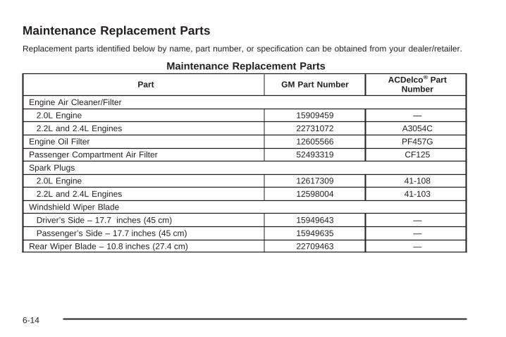
Maintenance Replacement PartsReplacement parts identified below by name, part number, or specification can be obtained from your dealer/retailer.
Maintenance Replacement Parts
Part GM Part Number ACDelco® PartNumber
Engine Air Cleaner/Filter
2.0L Engine 15909459 —
2.2L and 2.4L Engines 22731072 A3054C
Engine Oil Filter 12605566 PF457G
Passenger Compartment Air Filter 52493319 CF125
Spark Plugs
2.0L Engine 12617309 41-108
2.2L and 2.4L Engines 12598004 41-103
Windshield Wiper Blade
Driver’s Side – 17.7 inches (45 cm) 15949643 —
Passenger’s Side – 17.7 inches (45 cm) 15949635 —
Rear Wiper Blade – 10.8 inches (27.4 cm) 22709463 —
6-14

Engine Drive Belt Routing
2.0L L4, 2.2L L4 and 2.4L L4 Engines
6-15
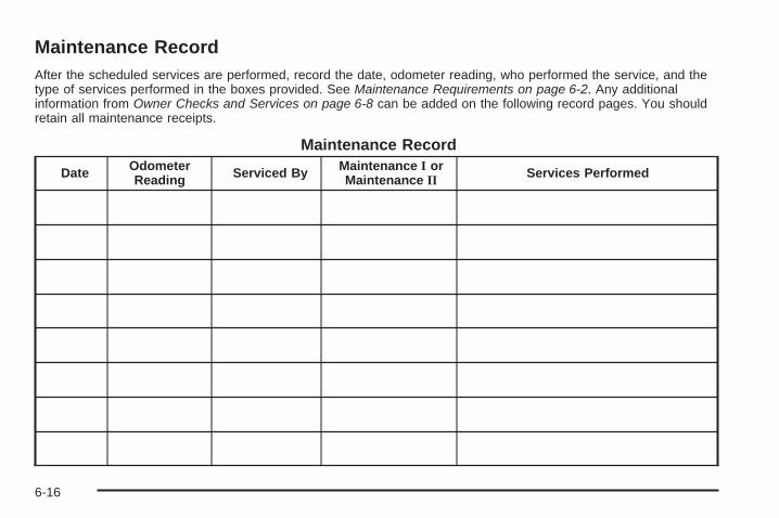
Maintenance RecordAfter the scheduled services are performed, record the date, odometer reading, who performed the service, and thetype of services performed in the boxes provided. See Maintenance Requirements on page 6-2. Any additionalinformation from Owner Checks and Services on page 6-8 can be added on the following record pages. You shouldretain all maintenance receipts.
Maintenance Record
Date OdometerReading Serviced By Maintenance I or
Maintenance II Services Performed
6-16

Maintenance Record (cont’d)
Date OdometerReading Serviced By Maintenance I or
Maintenance II Services Performed
6-17
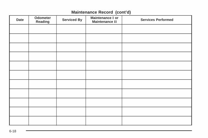
Maintenance Record (cont’d)
Date OdometerReading Serviced By Maintenance I or
Maintenance II Services Performed
6-18

Customer Assistance and Information ...............7-2Customer Satisfaction Procedure ......................7-2Online Owner Center ......................................7-4Customer Assistance for Text Telephone
(TTY) Users ...............................................7-4Customer Assistance Offices ............................7-5GM Mobility Reimbursement Program ................7-6Roadside Assistance Program ..........................7-6Scheduling Service Appointments .....................7-8Courtesy Transportation ...................................7-9Collision Damage Repair ................................7-10
Reporting Safety Defects ................................7-13Reporting Safety Defects to the
United States Government ..........................7-13Reporting Safety Defects to the Canadian
Government ..............................................7-14Reporting Safety Defects to
General Motors .........................................7-14Service Publications Ordering Information .........7-15
Vehicle Data Recording and Privacy ................7-16Event Data Recorders ...................................7-16OnStar® ......................................................7-17Navigation System ........................................7-17Radio Frequency Identification (RFID) ..............7-17
Section 7 Customer Assistance Information
7-1
Customer Assistance andInformation
Customer Satisfaction ProcedureYour satisfaction and goodwill are important toyour dealer and to Chevrolet. Normally, any concernswith the sales transaction or the operation of yourvehicle will be resolved by your dealer’s sales or servicedepartments. Sometimes, however, despite the bestintentions of all concerned, misunderstandings canoccur. If your concern has not been resolved to yoursatisfaction, the following steps should be taken:
STEP ONE: Discuss your concern with a member ofdealership management. Normally, concerns canbe quickly resolved at that level. If the matter hasalready been reviewed with the sales, service, or partsmanager, contact the owner of the dealership or thegeneral manager.
STEP TWO: If after contacting a member of dealershipmanagement, it appears your concern cannot beresolved by the dealership without further help, in theU.S., contact the Chevrolet Customer Assistance Centerby calling 1-800-222-1020. In Canada, contact GeneralMotors of Canada Customer Communication Centreby calling 1-800-263-3777 (English) or 1-800-263-7854(French).
We encourage you to call the toll-free number in orderto give your inquiry prompt attention. Please havethe following information available to give the CustomerAssistance Representative:
• Vehicle Identification Number (VIN). This isavailable from the vehicle registration or title, orthe plate at the top left of the instrument paneland visible through the windshield.
• Dealership name and location.
• Vehicle delivery date and present mileage(kilometers).
When contacting Chevrolet, please remember that yourconcern will likely be resolved at a dealer’s facility.That is why we suggest you follow Step One first if youhave a concern.
STEP THREE — U.S. Owners: Both General Motorsand your dealer are committed to making sure youare completely satisfied with your new vehicle. However,if you continue to remain unsatisfied after followingthe procedure outlined in Steps One and Two,you should file with the Better Business Bureau (BBB)Auto Line Program to enforce your rights.
The BBB Auto Line Program is an out of court programadministered by the Council of Better BusinessBureaus to settle automotive disputes regarding vehiclerepairs or the interpretation of the New VehicleLimited Warranty.
7-2

Although you may be required to resort to this informaldispute resolution program prior to filing a courtaction, use of the program is free of charge and yourcase will generally be heard within 40 days. If you do notagree with the decision given in your case, you mayreject it and proceed with any other venue for reliefavailable to you.
You may contact the BBB Auto Line Program using thetoll-free telephone number or write them at thefollowing address:
BBB Auto Line ProgramCouncil of Better Business Bureaus, Inc.4200 Wilson BoulevardSuite 800Arlington, VA 22203-1838
Telephone: 1-800-955-5100
This program is available in all 50 states and theDistrict of Columbia. Eligibility is limited by vehicle age,mileage, and other factors. General Motors reservesthe right to change eligibility limitations and/ordiscontinue its participation in this program.
STEP THREE — Canadian Owners: In the event thatyou do not feel your concerns have been addressedafter following the procedure outlined in Steps 1 and 2,General Motors of Canada Limited wants you to beaware of its participation in a no-chargeMediation/Arbitration Program.
General Motors of Canada Limited has committed tobinding arbitration of owner disputes involvingfactory-related vehicle service claims. The programprovides for the review of the facts involved by animpartial third party arbiter, and may include an informalhearing before the arbiter. The program is designedso that the entire dispute settlement process, fromthe time you file your complaint to the final decision,should be completed in about 70 days. We believe ourimpartial program offers advantages over courts inmost jurisdictions because it is informal, quick, andfree of charge.
For further information concerning eligibility in theCanadian Motor Vehicle Arbitration Plan (CAMVAP),call toll-free 1-800-207-0685. Alternatively, you may callthe General Motors Customer Communication Centre,1-800-263-3777 (English), 1-800-263-7854 (French),or you may write to:
The Mediation/Arbitration Programc/o Customer Communication CentreGeneral Motors of Canada LimitedMail Code: CA1-163-0051908 Colonel Sam DriveOshawa, Ontario L1H 8P7
Your inquiry should be accompanied by your VehicleIdentification Number (VIN).
7-3

Online Owner Center
(United States only)The Owner Center is a resource for your GM ownershipneeds. Specific vehicle information can be found inone place.
The Online Owner Center allows you to:
• Get e-mail service reminders.
• Access information about your specific vehicle,including tips and videos and an electronicversion of this owner manual.
• Keep track of your vehicle’s service history andmaintenance schedule.
• Find GM dealers/retailers for service nationwide.
• Receive special promotions and privileges onlyavailable to members.
Refer to www.MyGMLink.com on the web for updatedinformation and to register your vehicle.
My GM Canada (Canada only)My GM Canada is a password-protected section ofgmcanada.com where you can save information on GMvehicles, get personalized offers, and use handytools and forms with greater ease.
Here are a few of the valuable tools and services youwill have access to:
− My Showroom: Find and save information onvehicles and current offers in your area.
− My Dealers/Retailers: Save details such asaddress and phone number for each of yourpreferred GM Dealers or Retailers.
− My Driveway: Receive service reminders andhelpful advice on owning and maintainingyour vehicle.
− My Preferences: Manage your profile, subscribeto E-News and use tools and forms withgreater ease.
To sign up to My GM Canada, visit the My GM Canadasection within www.gmcanada.com.
Customer Assistance for TextTelephone (TTY) UsersTo assist customers who are deaf, hard of hearing, orspeech-impaired and who use Text Telephones (TTYs),Chevrolet has TTY equipment available at its CustomerAssistance Center. Any TTY user in the U.S. cancommunicate with Chevrolet by dialing:1-800-833-CHEV (2438). (TTY users in Canada candial 1-800-263-3830.)
7-4

Customer Assistance OfficesChevrolet encourages customers to call the toll-freenumber for assistance. However, if a customer wishesto write or e-mail Chevrolet, the letter should beaddressed to:
United States — Customer AssistanceChevrolet Motor DivisionChevrolet Customer Assistance CenterP.O. Box 33170Detroit, MI 48232-5170
www.Chevrolet.com1-800-222-10201-800-833-2438 (For Text Telephone devices (TTYs))Roadside Assistance: 1-800-CHEV-USA (243-8872)Fax Number: 313-381-0022
From Puerto Rico:1-800-496-9992 (English)1-800-496-9993 (Spanish)Fax Number: 313-381-0022
From U.S. Virgin Islands:1-800-496-9994Fax Number: 313-381-0022
Canada — Customer AssistanceGeneral Motors of Canada LimitedCustomer Communication Centre, CA1-163-0051908 Colonel Sam DriveOshawa, Ontario L1H 8P7
www.gmcanada.com1-800-263-3777 (English)1-800-263-7854 (French)1-800-263-3830 (For Text Telephone devices (TTYs))Roadside Assistance: 1-800-268-6800
Overseas — Customer AssistancePlease contact the local General Motors Business Unit.
Mexico, Central America andCaribbean Islands/Countries(Except Puerto Rico and U.S. VirginIslands) — Customer Assistance
General Motors de Mexico, S. de R.L. de C.V.Customer Assistance CenterPaseo de la Reforma # 2740Col. Lomas de BezaresC.P. 11910, Mexico, D.F.01-800-508-0000Long Distance: 011-52-53 29 0 800
7-5

GM Mobility ReimbursementProgram
This program, available to qualified applicants,can reimburse you up to $1,000 of the cost ofeligible aftermarket adaptive equipment requiredfor your vehicle, such as hand controls or awheelchair/scooter lift.
The offer is available for a very limited period of timefrom the date of vehicle purchase/lease. For moredetails, or to determine your vehicle’s eligibility, visitgmmobility.com or call the GM Mobility AssistanceCenter at 1-800-323-9935. Text telephone (TTY) users,call 1-800-833-9935.
General Motors of Canada also has a Mobility Program.Call 1-800-GM-DRIVE (463-7483) for details. TTYusers call 1-800-263-3830.
Roadside Assistance ProgramFor vehicles purchased in the U.S., call1-800-CHEV-USA (1-800-243-8872);(Text telephone (TTY): 1-888-889-2438).
For vehicles purchased in Canada, call 1-800-268-6800.
Service is available 24 hours a day, 365 days a year.
As the owner of a new Chevrolet vehicle, you areautomatically enrolled in the Chevrolet RoadsideAssistance program.
Who is Covered?Roadside Assistance coverage is for the vehicleoperator, regardless of ownership. In Canada, a persondriving this vehicle without the consent of the owneris not eligible for coverage.
Services ProvidedThe following services are provided in the U.S. andCanada up to 5 years/100,000 miles (160 000 km),whichever occurs first, and, in Canada only, upto a maximum coverage of $100.
• Fuel Delivery: Delivery of enough fuel for thevehicle to get to the nearest service station(approximately $5 in Canada). In Canada, serviceto provide diesel may be restricted. For safetyreasons, propane and other alternative fuels will notbe provided through this service.
7-6
• Lock-out Service: Lock-out service will be coveredat no charge if you are unable to gain entry intoyour vehicle. A remote unlock may be available ifyou have an active OnStar® subscription. To ensuresecurity, the driver must present personalidentification before lock-out service is provided. InCanada, the vehicle registration is also required.
• Emergency Tow From a Public Roadway orHighway: Tow to the nearest dealership for warrantyservice or in the event of a vehicle-disabling crash.Winch-out assistance is provided when the vehicle ismired in sand, mud, or snow.
• Flat Tire Change: Installation of a spare tire in goodcondition, when equipped and properly inflated, iscovered at no charge. The customer is responsiblefor the repair or replacement of the tire if not coveredby a warrantable failure.
• Jump Start: A battery jump start is covered at nocharge if the vehicle does not start.
• Trip Routing Service (Canada only): Upon request,Roadside Assistance will send you detailed,computer personalized maps, highlighting yourchoice of either the most direct route or the mostscenic route to your destination, anywhere in NorthAmerica, along with helpful travel informationpertaining to your trip.
Please allow three weeks before your planneddeparture date. Trip routing requests will be limited tosix per calendar year.
• Trip Interruption Benefits and Assistance(Canada only): In the event of a warranty relatedvehicle disablement, while en route and over250 kilometres from the original point of departure,you may qualify for trip interruption expenseassistance. This assistance covers reasonablereimbursement of up to a maximum of $500(Canadian) for (A) meals (maximum of $50/day),(B) lodging (maximum of $100/night) and(C) alternate ground transportation (maximum of$40/day). This benefit is to assist you with some ofthe unplanned expense you may incur while waitingfor your vehicle to be repaired.Pre-authorization, original detailed receipts and acopy of the repair order are required.Once authorization has been given, your advisor willhelp you make any necessary arrangements andexplain how to claim for trip interruption expenseassistance.
• Alternative Service (Canada only): There may betimes, when Roadside Assistance cannot providetimely assistance. Your advisor may authorize you tosecure local emergency road service, and you will bereimbursed up to $100 upon submission of theoriginal receipt to Roadside Assistance.
7-7

In many instances, mechanical failures may be covered.However, any cost for parts and labor for non-warrantyrepairs are the responsibility of the driver.
Chevrolet and General Motors of Canada Limitedreserve the right to limit services or reimbursement toan owner or driver when, in their sole discretion,the claims become excessive in frequency or type ofoccurrence.
Calling for AssistanceFor prompt and efficient assistance when calling, pleaseprovide the following to the Roadside AssistanceRepresentative:
• Your name, home address, and home telephonenumber
• Telephone number of your location
• Location of the vehicle
• Model, year, color, and license plate number ofthe vehicle
• Odometer reading, Vehicle Identification Number(VIN), and delivery date of the vehicle
• Description of the problem
Towing and Road Service ExclusionsSpecifically excluded from Roadside Assistancecoverage are towing or services for vehicles operatedon a non-public roadway or highway, fines, impoundtowing caused by a violation of local, Municipal, State,Provincial, or Federal law, and mounting, dismounting orchanging of snow tires, chains, or other tractiondevices.
Roadside Assistance is not part of or included in thecoverage provided by the New Vehicle Limited Warranty.Chevrolet and General Motors of Canada Limitedreserve the right to make any changes or discontinuethe Roadside Assistance program at any time withoutnotification.
Scheduling Service AppointmentsWhen your vehicle requires warranty service, contactyour dealer/retailer and request an appointment.By scheduling a service appointment and advising yourservice consultant of your transportation needs, yourdealer/retailer can help minimize your inconvenience.
If your vehicle cannot be scheduled into the servicedepartment immediately, keep driving it until it can bescheduled for service, unless, of course, the problem issafety-related. If it is, please call your dealership/retailer,let them know this, and ask for instructions.
7-8

If the dealer/retailer requests that you simply drop thevehicle off for service, you are urged to do so as early inthe work day as possible to allow for the same dayrepair.
Courtesy TransportationTo enhance your ownership experience, we and ourparticipating dealers are proud to offer CourtesyTransportation, a customer support program for vehicleswith the Bumper to Bumper (Base Warranty Coverageperiod in Canada) and extended powertrain warrantyin both the U.S. and Canada.
Several courtesy transportation options are available toassist in reducing your inconvenience when warrantyrepairs are required.
Courtesy Transportation is not a part of the New VehicleLimited Warranty. A separate booklet entitled “Warrantyand Owner Assistance Information” furnished witheach new vehicle provides detailed warranty coverageinformation.
Transportation OptionsWarranty service can generally be completed while youwait. However, if you are unable to wait, GM helpsto minimize your inconvenience by providing severaltransportation options.
Depending on the circumstances, your dealer can offeryou one of the following:
Shuttle ServiceShuttle service is the preferred means of offeringCourtesy Transportation. Dealers may provide you withshuttle service to get you to your destination withminimal interruption of your daily schedule. This includesone-way or round trip shuttle service within reasonabletime and distance parameters of the dealer’s area.
Public Transportation or FuelReimbursementIf your vehicle requires overnight warranty repairs, andpublic transportation is used instead of the dealer’sshuttle service, the expense must be supportedby original receipts and can only be up to the maximumamount allowed by GM for shuttle service. In addition,for U.S. customers, should you arrange transportationthrough a friend or relative, limited reimbursementfor reasonable fuel expenses may be available. Claimamounts should reflect actual costs and be supported byoriginal receipts. See your dealer for informationregarding the allowance amounts for reimbursement offuel or other transportation costs.
7-9

Courtesy Rental VehicleYour dealer may arrange to provide you with a courtesyrental vehicle or reimburse you for a rental vehiclethat you obtain if your vehicle is kept for an overnightwarranty repair. Rental reimbursement will be limitedand must be supported by original receipts. Thisrequires that you sign and complete a rental agreementand meet state/provincial, local, and rental vehicleprovider requirements. Requirements vary and mayinclude minimum age requirements, insurance coverage,credit card, etc. You are responsible for fuel usagecharges and may also be responsible for taxes, levies,usage fees, excessive mileage, or rental usagebeyond the completion of the repair.
It may not be possible to provide a like-vehicle as acourtesy rental.
Additional Program InformationAll program options, such as shuttle service, may not beavailable at every dealer. Please contact your dealerfor specific information about availability. All CourtesyTransportation arrangements will be administeredby appropriate dealer personnel.
General Motors reserves the right to unilaterally modify,change or discontinue Courtesy Transportation atany time and to resolve all questions of claim eligibilitypursuant to the terms and conditions describedherein at its sole discretion.
Collision Damage RepairIf your vehicle is involved in a collision and it isdamaged, have the damage repaired by a qualifiedtechnician using the proper equipment and qualityreplacement parts. Poorly performed collision repairsdiminish your vehicle’s resale value, and safetyperformance can be compromised in subsequentcollisions.
Collision PartsGenuine GM Collision parts are new parts made with thesame materials and construction methods as the partswith which your vehicle was originally built. Genuine GMCollision parts are your best choice to ensure that yourvehicle’s designed appearance, durability, and safety arepreserved. The use of Genuine GM parts can helpmaintain your GM New Vehicle Warranty.
Recycled original equipment parts may also be used forrepair. These parts are typically removed from vehiclesthat were total losses in prior crashes. In most cases,the parts being recycled are from undamaged sectionsof the vehicle. A recycled original equipment GMpart, may be an acceptable choice to maintain yourvehicle’s originally designed appearance and safetyperformance, however, the history of these parts is notknown. Such parts are not covered by your GM NewVehicle Limited Warranty, and any related failuresare not covered by that warranty.
7-10
Aftermarket collision parts are also available. These aremade by companies other than GM and may nothave been tested for your vehicle. As a result, theseparts may fit poorly, exhibit prematuredurability/corrosion problems, and may not performproperly in subsequent collisions. Aftermarket parts arenot covered by your GM New Vehicle LimitedWarranty, and any vehicle failure related to such partsare not covered by that warranty.
Repair FacilityGM also recommends that you choose a collision repairfacility that meets your needs before you ever needcollision repairs. Your dealer/retailer may have acollision repair center with GM-trained technicians andstate of the art equipment, or be able to recommenda collision repair center that has GM-trained techniciansand comparable equipment.
Insuring Your VehicleProtect your investment in your GM vehicle withcomprehensive and collision insurance coverage. Thereare significant differences in the quality of coverageafforded by various insurance policy terms. Manyinsurance policies provide reduced protection to yourGM vehicle by limiting compensation for damage repairsby using aftermarket collision parts. Some insurancecompanies will not specify aftermarket collisionparts. When purchasing insurance, we recommend thatyou assure your vehicle will be repaired with GMoriginal equipment collision parts. If such insurancecoverage is not available from your current insurancecarrier, consider switching to another insurance carrier.
If your vehicle is leased, the leasing company mayrequire you to have insurance that assures repairs withGenuine GM Original Equipment Manufacturer (OEM)parts or Genuine Manufacturer replacement parts. Readyour lease carefully, as you may be charged at theend of your lease for poor quality repairs.
7-11

If a Crash OccursHere is what to do if you are involved in a crash.
• Try to relax and then check to make sure you are allright. If you are uninjured, make sure that no one elsein your vehicle, or the other vehicle, is injured.
• If there has been an injury, call emergency servicesfor help. Do not leave the scene of a crash until allmatters have been taken care of. Move your vehicleonly if its position puts you in danger or you areinstructed to move it by a police officer.
• Give only the necessary and requested informationto police and other parties involved in the crash. Donot discuss your personal condition, mental frame ofmind, or anything unrelated to the crash. This willhelp guard against post-crash legal action.
• If you need roadside assistance, call GM RoadsideAssistance. See Roadside Assistance Program onpage 7-6 for more information.
• If your vehicle cannot be driven, know where thetowing service will be taking it. Get a card from thetow truck operator or write down the driver’s name,the service’s name, and the phone number.
• Remove any valuables from your vehicle before it istowed away. Make sure this includes your insuranceinformation and registration if you keep these itemsin your vehicle.
• Gather the important information you will need fromthe other driver. Things like name, address, phonenumber, driver’s license number, vehicle licenseplate, vehicle make, model and model year, VehicleIdentification Number (VIN), insurance company andpolicy number, and a general description of thedamage to the other vehicle.
• If possible, call your insurance company from thescene of the crash. They will walk you through theinformation they will need. If they ask for a policereport, phone or go to the police departmentheadquarters the next day and you can get a copy ofthe report for a nominal fee. In some states/provinceswith “no fault” insurance laws, a report may not benecessary. This is especially true if there are noinjuries and both vehicles are driveable.
• Choose a reputable collision repair facility for yourvehicle. Whether you select a dealer/retailer or aprivate collision repair facility to fix the damage,make sure you are comfortable with them.Remember, you will have to feel comfortable withtheir work for a long time.
• Once you have an estimate, read it carefully andmake sure you understand what work will beperformed on your vehicle. If you have a question,ask for an explanation. Reputable shops welcomethis opportunity.
7-12

Managing the Vehicle Damage RepairProcessIn the event that your vehicle requires damage repairs,GM recommends that you take an active role in itsrepair. If you have a pre-determined repair facility ofchoice, take your vehicle there, or have it towed there.Specify to the facility that any required replacementcollision parts be original equipment parts, either newGenuine GM parts or recycled original GM parts.Remember, recycled parts will not be covered by yourGM vehicle warranty.
Insurance pays the bill for the repair, but you must livewith the repair. Depending on your policy limits, yourinsurance company may initially value the repair usingaftermarket parts. Discuss this with your repairprofessional, and insist on Genuine GM parts.Remember if your vehicle is leased you may beobligated to have the vehicle repaired with Genuine GMparts, even if your insurance coverage does not paythe full cost.
If another party’s insurance company is paying for therepairs, you are not obligated to accept a repairvaluation based on that insurance company’s collisionpolicy repair limits, as you have no contractual limits withthat company. In such cases, you can have control ofthe repair and parts choices as long as cost stays withinreasonable limits.
Reporting Safety Defects
Reporting Safety Defects to theUnited States GovernmentIf you believe that your vehicle has a defect whichcould cause a crash or could cause injury ordeath, you should immediately inform the NationalHighway Traffic Safety Administration (NHTSA)in addition to notifying General Motors.
If NHTSA receives similar complaints, it may openan investigation, and if it finds that a safetydefect exists in a group of vehicles, it may order arecall and remedy campaign. However, NHTSAcannot become involved in individual problemsbetween you, your dealer/retailer, or GeneralMotors.
7-13
To contact NHTSA, you may call the VehicleSafety Hotline toll-free at 1-888-327-4236 (TTY:1-800-424-9153); go to http://www.safercar.gov;or write to:
Administrator, NHTSA400 Seventh Street, SW.Washington D.C., 20590
You can also obtain other information about motorvehicle safety from http://www.safercar.gov.
Reporting Safety Defects tothe Canadian GovernmentIf you live in Canada, and you believe that your vehiclehas a safety defect, notify Transport Canadaimmediately, in addition to notifying General Motors ofCanada Limited. Call them at 1-800-333-0510 orwrite to:
Transport CanadaRoad Safety Branch2780 Sheffield RoadOttawa, Ontario K1B 3V9
Reporting Safety Defects toGeneral MotorsIn addition to notifying NHTSA (or Transport Canada)in a situation like this, please notify General Motors.
Call 1-800-222-1020, or write:
Chevrolet Motor DivisionChevrolet Customer Assistance CenterP.O. Box 33170Detroit, MI 48232-5170
In Canada, call 1-800-263-3777 (English) or1-800-263-7854 (French), or write:
General Motors of Canada LimitedCustomer Communication Centre, CA1-163-0051908 Colonel Sam DriveOshawa, Ontario L1H 8P7
7-14
Service Publications OrderingInformation
Service ManualsService Manuals have the diagnosis and repairinformation on engines, transmission, axle suspension,brakes, electrical, steering, body, etc.
Service BulletinsService Bulletins’ give additional technical serviceinformation needed to knowledgeably service GeneralMotors cars and trucks. Each bulletin containsinstructions to assist in the diagnosis and service ofyour vehicle.
Owner InformationOwner publications are written specifically for ownersand intended to provide basic operational informationabout the vehicle. The owner manual includes theMaintenance Schedule for all models.
In-Portfolio: Includes a Portfolio, Owner Manual, andWarranty Booklet.
RETAIL SELL PRICE: $35.00 (U.S.) plus processing fee
Without Portfolio: Owner Manual only.
RETAIL SELL PRICE: $25.00 (U.S.) plus processing fee
Current and Past Model Order FormsTechnical Service Bulletins and Manuals are availablefor current and past model GM vehicles. To requestan order form, specify year and model name ofthe vehicle.
ORDER TOLL FREE: 1-800-551-4123Monday-Friday 8:00 AM - 6:00 PMEastern TimeFor Credit Card Orders Only(VISA-MasterCard-Discover), visit Helm, Inc. on theWorld Wide Web at: www.helminc.com
Or you can write to:
Helm, IncorporatedP.O. Box 07130Detroit, MI 48207
Prices are subject to change without notice and withoutincurring obligation. Allow ample time for delivery.
Note to Canadian Customers: All listed prices arequoted in U.S. funds. Canadian residents are to makechecks payable in U.S. funds.
7-15
Vehicle Data Recording andPrivacyYour GM vehicle has a number of sophisticatedcomputers that record information about the vehicle’sperformance and how it is driven. For example,your vehicle uses computer modules to monitor andcontrol engine and transmission performance, to monitorthe conditions for airbag deployment and deployairbags in a crash and, if so equipped, to provideantilock braking to help the driver control the vehicle.These modules may store data to help yourdealer/retailer technician service your vehicle. Somemodules may also store data about how you operate thevehicle, such as rate of fuel consumption or averagespeed. These modules may also retain the owner’spersonal preferences, such as radio pre-sets, seatpositions, and temperature settings.
Event Data RecordersThis vehicle has an Event Data Recorder (EDR). Themain purpose of an EDR is to record, in certain crash ornear crash-like situations, such as an airbag deploymentor hitting a road obstacle, data that will assist inunderstanding how a vehicle’s systems performed. TheEDR is designed to record data related to vehicledynamics and safety systems for a short period of time,typically 30 seconds or less. The EDR in this vehicleis designed to record such data as:
• How various systems in your vehicle were operating
• Whether or not the driver and passenger safetybelts were buckled/fastened
• How far, if at all, the driver was pressing theaccelerator and/or brake pedal
• How fast the vehicle was traveling
This data can help provide a better understanding of thecircumstances in which crashes and injuries occur.Important: EDR data is recorded by your vehicle onlyif a non-trivial crash situation occurs; no data isrecorded by the EDR under normal driving conditionsand no personal data (e.g., name, gender, age,and crash location) is recorded. However, other parties,such as law enforcement, could combine the EDRdata with the type of personally identifying data routinelyacquired during a crash investigation.
7-16
To read data recorded by an EDR, special equipment isrequired, and access to the vehicle or the EDR isneeded. In addition to the vehicle manufacturer, otherparties, such as law enforcement, that have the specialequipment, can read the information if they haveaccess to the vehicle or the EDR.
GM will not access this data or share it with othersexcept: with the consent of the vehicle owner or, if thevehicle is leased, with the consent of the lessee; inresponse to an official request of police or similargovernment office; as part of GM’s defense of litigationthrough the discovery process; or, as required bylaw. Data that GM collects or receives may also be usedfor GM research needs or may be made available toothers for research purposes, where a need is shownand the data is not tied to a specific vehicle orvehicle owner.
OnStar®
If your vehicle has OnStar and you subscribe to theOnStar services, please refer to the OnStar Terms andConditions for information on data collection anduse. See also OnStar® System on page 2-44 in thismanual for more information.
Navigation SystemIf your vehicle has a navigation system, use of thesystem may result in the storage of destinations,addresses, telephone numbers, and other tripinformation. Refer to the navigation system operatingmanual for information on stored data and for deletioninstructions.
Radio FrequencyIdentification (RFID)RFID technology is used in some vehicles for functionssuch as tire pressure monitoring and ignition systemsecurity, as well as in connection with conveniencessuch as key fobs for remote door locking/unlocking andstarting, and in-vehicle transmitters for garage dooropeners. RFID technology in GM vehicles does not useor record personal information or link with any otherGM system containing personal information.
7-17

✍ NOTES
7-18
AAccessories and Modifications ............................ 5-3Adding Equipment to Your Airbag-Equipped
Vehicle ....................................................... 1-71Additives, Fuel ................................................. 5-6Add-On Electrical Equipment ........................... 5-118Air Cleaner/Filter, Engine ................................. 5-20Air Conditioning .............................................. 3-23Airbag
Passenger Status Indicator ........................... 3-32Readiness Light .......................................... 3-31
Airbag System ................................................ 1-57What Will You See After an Airbag Inflates? .... 1-64When Should an Airbag Inflate? .................... 1-62Where Are the Airbags? ............................... 1-60
Airbag SystemsAdding Equipment to Your Airbag-Equipped
Vehicle ................................................... 1-71How Does an Airbag Restrain? ...................... 1-63Passenger Sensing System ........................... 1-65Servicing Your Airbag-Equipped Vehicle .......... 1-70What Makes an Airbag Inflate? ...................... 1-63
Antenna, Fixed Mast ....................................... 3-80Antenna, XM™ Satellite Radio Antenna System ..... 3-80Antilock Brake System (ABS) ............................. 4-5Antilock Brake, System Warning Light ................ 3-36
Appearance CareAluminum or Chrome-Plated Wheels ............. 5-115Care of Safety Belts ................................... 5-112Chemical Paint Spotting .............................. 5-116Cleaning Exterior Lamps/Lenses .................. 5-113Fabric/Carpet ............................................ 5-111Finish Care ............................................... 5-114Finish Damage .......................................... 5-116Instrument Panel, Vinyl, and Other Plastic
Surfaces ............................................... 5-112Interior Cleaning ........................................ 5-110Sheet Metal Damage .................................. 5-116Tires ........................................................ 5-116Underbody Maintenance ............................. 5-116Vehicle Care/Appearance Materials ............... 5-117Washing Your Vehicle ................................. 5-113Weatherstrips ............................................ 5-113Windshield and Wiper Blades ...................... 5-114
Appointments, Scheduling Service ....................... 7-8Ashtray ......................................................... 3-22Audio System ................................................. 3-59
Audio Steering Wheel Controls ...................... 3-79Fixed Mast Antenna ..................................... 3-80Radio Reception .......................................... 3-79Setting the Clock ......................................... 3-60Theft-Deterrent Feature ................................ 3-78XM™ Satellite Radio Antenna System ............ 3-80
1
Audio System(s) ............................................. 3-62Automatic Door Lock ....................................... 2-10Automatic Headlamp System ............................ 3-17Automatic Transmission
Fluid .......................................................... 5-23Operation ................................................... 2-28
BBattery .......................................................... 5-37
Electric Power Management .......................... 3-20Run-Down Protection ................................... 3-20
Boost Gage ................................................... 3-45Brake
Emergencies ................................................ 4-6Brakes .......................................................... 5-34
System Warning Light .................................. 3-35Braking ........................................................... 4-3Braking in Emergencies ..................................... 4-6Break-In, New Vehicle ..................................... 2-21Bulb Replacement ........................................... 5-46
Center High-Mounted Stoplamp (CHMSL) ........ 5-48Halogen Bulbs ............................................ 5-46Headlamp Aiming ........................................ 5-43Headlamps, Front Turn Signal, and Parking
Lamps .................................................... 5-46
Bulb Replacement (cont.)License Plate Lamps .................................... 5-50Replacement Bulbs ...................................... 5-50Taillamps, Turn Signal, Stoplamps and
Back-up Lamps ........................................ 5-49Buying New Tires ........................................... 5-69
CCalibration ............................................. 2-39, 2-41California Fuel .................................................. 5-6California Perchlorate Materials Requirements ....... 5-4California Proposition 65 Warning ....................... 5-3Canadian Owners ................................................ iiCapacities and Specifications .......................... 5-125Carbon Monoxide ........................... 2-37, 4-22, 4-34Care of
Safety Belts .............................................. 5-112Cargo, Rear Side Door .................................... 2-12CD, MP3 ....................................................... 3-72Center High-Mounted Stoplamp (CHMSL) ........... 5-48Chains, Tire ................................................... 5-74Charging System Light .................................... 3-34Check
Engine Light ............................................... 3-40
2
Checking Things Under the Hood ...................... 5-10Chemical Paint Spotting ................................. 5-116Child Restraints
Child Restraint Systems ............................... 1-40Infants and Young Children ........................... 1-36Lower Anchors and Tethers for Children .......... 1-43Older Children ............................................. 1-33Securing a Child Restraint in a Rear Seat
Position .................................................. 1-51Securing a Child Restraint in the Right
Front Seat Position ................................... 1-53Where to Put the Restraint ........................... 1-42
Cigarette Lighter ............................................. 3-22Cleaning
Aluminum or Chrome-Plated Wheels ............. 5-115Exterior Lamps/Lenses ................................ 5-113Fabric/Carpet ............................................ 5-111Finish Care ............................................... 5-114Instrument Panel, Vinyl, and Other Plastic
Surfaces ............................................... 5-112Interior ..................................................... 5-110Tires ........................................................ 5-116Underbody Maintenance ............................. 5-116Washing Your Vehicle ................................. 5-113Weatherstrips ............................................ 5-113Windshield and Wiper Blades ...................... 5-114
Climate Control System ................................... 3-23Air Filter, Passenger Compartment ................. 3-26Outlet Adjustment ........................................ 3-26
Clock, Setting ................................................. 3-60Clutch, Hydraulic ............................................. 5-23Collision Damage Repair .................................. 7-10Compact Spare Tire ...................................... 5-109Compass ............................................... 2-39, 2-41Compressor Kit, Tire Sealant ............................ 5-76Content Theft-Deterrent .................................... 2-18Control of a Vehicle .......................................... 4-3Convenience Net ............................................ 2-51Coolant
Engine Temperature Gage ............................ 3-39Engine Temperature Warning Light ................. 3-38Heater, Engine ............................................ 2-27
Cooling System .............................................. 5-28Cruise Control ................................................ 3-12Cupholder(s) .................................................. 2-47Customer Assistance Information
Courtesy Transportation .................................. 7-9Customer Assistance for Text Telephone (TTY)
Users ....................................................... 7-4Customer Assistance Offices ........................... 7-5Customer Satisfaction Procedure ..................... 7-2GM Mobility Reimbursement Program ............... 7-6
3

Customer Assistance Information (cont.)Reporting Safety Defects to General Motors .... 7-14Reporting Safety Defects to the Canadian
Government ............................................ 7-14Reporting Safety Defects to the United
States Government ................................... 7-13Roadside Assistance Program ......................... 7-6Service Publications Ordering Information ........ 7-15
DDaytime Running Lamps .................................. 3-16Defensive Driving ............................................. 4-2Delayed Locking ............................................. 2-10Differential, Limited-Slip .................................... 4-10Disc, MP3 ...................................................... 3-72Doing Your Own Service Work ........................... 5-4Dome Lamp ................................................... 3-19Door
Automatic Door Lock .................................... 2-10Delayed Locking .......................................... 2-10Locks .......................................................... 2-9Power Door Locks ......................................... 2-9Programmable Automatic Door Unlock ............ 2-10Rear Door Security Locks ............................. 2-11Rear Side Cargo ......................................... 2-12
DriverSeat Height Adjuster ...................................... 1-3
Driver Information Center (DIC) ......................... 3-46DIC Operation and Displays .......................... 3-46DIC Vehicle Personalization .......................... 3-54DIC Warnings and Messages ........................ 3-48
DrivingAt Night ..................................................... 4-18Before a Long Trip ...................................... 4-20Defensive ..................................................... 4-2Drunken ....................................................... 4-2Highway Hypnosis ....................................... 4-20Hill and Mountain Roads .............................. 4-20In Rain and on Wet Roads ........................... 4-18Rocking Your Vehicle to Get it Out ................. 4-26Winter ........................................................ 4-22
EEDR ............................................................. 7-16Electrical System
Add-On Equipment ..................................... 5-118Engine Compartment Fuse Block ................. 5-122Floor Console Fuse Block ........................... 5-120Fuses and Circuit Breakers ......................... 5-119Headlamp Wiring ....................................... 5-119
4

Electrical System (cont.)Power Windows and Other Power Options .... 5-119Windshield Wiper Fuses ............................. 5-119
Electronic Stability Control ................................ 4-10Electronic Stability Control Indicator Light ........... 3-37Engine
Air Cleaner/Filter ......................................... 5-20Check and Service Engine Soon Light ............ 3-40Coolant ...................................................... 5-24Coolant Heater ............................................ 2-27Coolant Temperature Gage ........................... 3-39Coolant Temperature Warning Light ................ 3-38Drive Belt Routing ....................................... 6-15Engine Compartment Overview ...................... 5-12Exhaust ..................................................... 2-37Oil ............................................................. 5-15Oil Life System ........................................... 5-19Overheating ................................................ 5-26Running While Parked .................................. 2-38Starting ...................................................... 2-25
Enhanced Traction System (ETS) ........................ 4-9Warning Light ............................................. 3-37
Entry/Exit Lighting ........................................... 3-19Event Data Recorders ..................................... 7-16Extender, Safety Belt ....................................... 1-32
FFilter
Engine Air Cleaner ...................................... 5-20Finish Damage ............................................. 5-116Fixed Mast Antenna ........................................ 3-80Flashers, Hazard Warning .................................. 3-6Flash-to-Pass ................................................... 3-8Flat Tire ........................................................ 5-75Flat Tire, Changing ......................................... 5-86Flat Tire, Storing ........................................... 5-106Fluid ............................................................. 5-23
Windshield Washer ...................................... 5-33Fog Lamp
Fog ........................................................... 3-18Fog Lamp Light .............................................. 3-44Folding Rear Seat ........................................... 1-10Folding Seatback, Passenger ............................. 1-8Front Console Storage Area ............................. 2-47Fuel ............................................................... 5-5
Additives ...................................................... 5-6California Fuel .............................................. 5-6Filling a Portable Fuel Container .................... 5-10Filling the Tank ............................................. 5-7Fuels in Foreign Countries .............................. 5-7
5
Fuel (cont.)Gage ......................................................... 3-44Gasoline Octane ........................................... 5-5Gasoline Specifications .................................. 5-5
FusesEngine Compartment Fuse Block ................. 5-122Floor Console Fuse Block ........................... 5-120Fuses and Circuit Breakers ......................... 5-119Windshield Wiper ....................................... 5-119
GGage
Boost ......................................................... 3-45Engine Coolant Temperature ......................... 3-39Fuel .......................................................... 3-44Speedometer .............................................. 3-30Tachometer ................................................. 3-30
GasolineOctane ........................................................ 5-5Specifications ............................................... 5-5
Glove Box ..................................................... 2-47GM Mobility Reimbursement Program .................. 7-6
HHazard Warning Flashers ................................... 3-6Head Restraints ............................................... 1-7Headlamp
Aiming ....................................................... 5-43Headlamp Wiring ........................................... 5-119Headlamps .................................................... 3-15
Bulb Replacement ....................................... 5-46Daytime Running Lamps ............................... 3-16Flash-to-Pass ............................................... 3-8Halogen Bulbs ............................................ 5-46Headlamps, Front Turn Signal, and Parking
Lamps .................................................... 5-46High/Low Beam Changer ................................ 3-8On Reminder .............................................. 3-16Wiper Activated ........................................... 3-16
Heated Seats ................................................... 1-4Heater ........................................................... 3-23Height Adjuster, Driver Seat ............................... 1-3Hideaway Rear Storage Bins ............................ 2-51Highbeam On Light ......................................... 3-44Highway Hypnosis ........................................... 4-20Hill and Mountain Roads .................................. 4-20
6

HoodChecking Things Under ................................ 5-10Release ..................................................... 5-11
Horn ............................................................... 3-6How to Wear Safety Belts Properly ................... 1-18Hydraulic Clutch ............................................. 5-23
IIgnition Positions ............................................. 2-22Infants and Young Children, Restraints ............... 1-36Inflation - Tire Pressure ................................... 5-60Inflator Kit, Tire ............................................... 5-76Instrument Panel
Overview ..................................................... 3-4Storage Area .............................................. 2-47
Instrument Panel (I/P)Brightness .................................................. 3-18Cluster ....................................................... 3-29
JJump Starting ................................................. 5-38
KKeyless Entry System ....................................... 2-4Keys ............................................................... 2-3
LLabeling, Tire Sidewall ..................................... 5-53Lamps
Dome ........................................................ 3-19Mirror Reading ............................................ 3-19Rear Reading ............................................. 3-19
Lap-Shoulder Belt ........................................... 1-26LATCH System
Child Restraints ........................................... 1-43License Plate Lamps ....................................... 5-50Liftgate
Carbon Monoxide ........................................ 2-12Light
Airbag Readiness ........................................ 3-31Antilock Brake System Warning ..................... 3-36Brake System Warning ................................. 3-35Charging System ......................................... 3-34Engine Coolant Temperature Warning ............. 3-38
7
Light (cont.)Enhanced Traction System (ETS) Warning
Light ...................................................... 3-37Fog Lamp .................................................. 3-44Highbeam On ............................................. 3-44Malfunction Indicator .................................... 3-40Oil Pressure ............................................... 3-43Passenger Airbag Status Indicator .................. 3-32Safety Belt Reminders .................................. 3-30Security ..................................................... 3-44Tire Pressure .............................................. 3-39Up-Shift ..................................................... 3-35
LightingEntry/Exit ................................................... 3-19
Lights ............................................................ 3-15Flash-to-Pass ............................................... 3-8High/Low Beam Changer ................................ 3-8On Reminder .............................................. 3-16
Limited-Slip Differential .................................... 4-10Loading Your Vehicle ....................................... 4-27Lockout Protection .......................................... 2-12Locks
Automatic Door Lock .................................... 2-10Delayed Locking .......................................... 2-10Door ........................................................... 2-9Lockout Protection ....................................... 2-12Power Door .................................................. 2-9Programmable Automatic Door Unlock ............ 2-10
Locks (cont.)Rear Door Security Locks ............................. 2-11
Loss of Control ............................................... 4-16Lumbar
Power Controls ............................................. 1-4
MMaintenance Schedule
Additional Required Services ........................... 6-6At Each Fuel Fill ........................................... 6-8At Least Once a Month .................................. 6-9At Least Once a Year .................................... 6-9Introduction .................................................. 6-2Maintenance Footnotes .................................. 6-7Maintenance Record .................................... 6-16Maintenance Replacement Parts .................... 6-14Maintenance Requirements ............................. 6-2Owner Checks and Services ........................... 6-8Recommended Fluids and Lubricants ............. 6-12Scheduled Maintenance ................................. 6-4Using .......................................................... 6-2Your Vehicle and the Environment ................... 6-2
Malfunction Indicator Light ................................ 3-40Manual Seats ................................................... 1-2Manual Transmission
Fluid .......................................................... 5-23Operation ................................................... 2-31
Manual, Using .................................................... iii
8

MessageDIC Warnings and Messages ........................ 3-48
Mirror Reading Lamps ..................................... 3-19Mirrors
Automatic Dimming Rearview with Compass .... 2-41Automatic Dimming Rearview with OnStar®
and Compass .......................................... 2-39Manual Rearview Mirror ................................ 2-39Outside Convex Mirror ................................. 2-43Outside Power Mirrors .................................. 2-43
MP3 ............................................................. 3-72MyGMLink.com ................................................ 7-4
NNavigation System, Privacy .............................. 7-17New Vehicle Break-In ...................................... 2-21
OOdometer ...................................................... 3-30Off-Road Recovery .......................................... 4-15Oil
Engine ....................................................... 5-15Pressure Light ............................................. 3-43
Oil, Engine Oil Life System .............................. 5-19Older Children, Restraints ................................ 1-33Online Owner Center ........................................ 7-4OnStar, Privacy .............................................. 7-17OnStar® System, see OnStar® Manual ............... 2-44Other Warning Devices ...................................... 3-6Outlet Adjustment ............................................ 3-26Outlets
Accessory Power ......................................... 3-20Outside
Convex Mirror ............................................. 2-43Power Mirrors ............................................. 2-43
Owner Checks and Services .............................. 6-8Owners, Canadian ............................................... ii
PPaint, Damage .............................................. 5-116Park Brake .................................................... 2-33Park (P)
Shifting Into ................................................ 2-34Shifting Out of ............................................ 2-36
ParkingOver Things That Burn ................................. 2-37
Parking Your Vehicle ....................................... 2-36Passenger Airbag Status Indicator ..................... 3-32Passenger Compartment Air Filter ..................... 3-26
9

Passenger Sensing System .............................. 1-65Passing ......................................................... 4-16PASS-Key® III+ .............................................. 2-19PASS-Key® III+ Operation ................................ 2-20Perchlorate Materials Requirements, California ...... 5-4Power
Door Locks .................................................. 2-9Electrical System ....................................... 5-119Lumbar Controls ........................................... 1-4Retained Accessory (RAP) ............................ 2-25Seat ............................................................ 1-3Windows .................................................... 2-16
Pressure Cap ................................................. 5-26Privacy .......................................................... 7-16
Event Data Recorders .................................. 7-16Navigation System ....................................... 7-17OnStar ....................................................... 7-17Radio Frequency Identification ....................... 7-17
Programmable Automatic Door Unlock ............... 2-10
RRadio Frequency Identification (RFID), Privacy .... 7-17Radios .......................................................... 3-59Radio(s) ........................................................ 3-62Radios
Reception ................................................... 3-79Setting the Clock ......................................... 3-60
Radios (cont.)Theft-Deterrent ............................................ 3-78
Rear Compartment Storage Panel/Cover ............ 2-48Rear Door Security Locks ................................ 2-11Rear Reading Lamps ...................................... 3-19Rear Side Cargo Door ..................................... 2-12Rear Storage Area .......................................... 2-48Rear Windshield Washer/Wiper ......................... 3-11Rearview Mirror, Automatic Dimming with
Compass .................................................... 2-41Rearview Mirror, Automatic Dimming with
OnStar® and Compass ................................. 2-39Rearview Mirrors ............................................. 2-39Reclining Seatbacks .......................................... 1-5Recommended Fluids and Lubricants ................. 6-12Recreational Vehicle Towing ............................. 4-32Remote Keyless Entry (RKE) System .................. 2-4Remote Keyless Entry (RKE) System, Operation ... 2-5Remote Vehicle Start ........................................ 2-7Removing the Flat Tire and Installing
the Spare Tire ................................... 5-90, 5-101Removing the Spare Tire and Tools ................... 5-87Replacement Bulbs ......................................... 5-50Replacement Parts, Maintenance ...................... 6-14Reporting Safety Defects
Canadian Government .................................. 7-14General Motors ........................................... 7-14United States Government ............................ 7-13
10

Restraint System CheckChecking the Restraint Systems .................... 1-72Replacing Restraint System Parts After a
Crash ..................................................... 1-73Retained Accessory Power (RAP) ...................... 2-25Roadside
Assistance Program ....................................... 7-6Rocking Your Vehicle to Get it Out .................... 4-26Roof Rack System .......................................... 2-50Routing, Engine Drive Belt ............................... 6-15Running the Engine While Parked ..................... 2-38
SSafety Belt
Reminder Light ............................................ 3-30Safety Belts
Care of .................................................... 5-112How to Wear Safety Belts Properly ................ 1-18Lap-Shoulder Belt ........................................ 1-26Safety Belt Extender .................................... 1-32Safety Belt Use During Pregnancy ................. 1-32Safety Belts Are for Everyone ....................... 1-12
Safety Warnings and Symbols .............................. iiiScheduled Maintenance ..................................... 6-4Seatback, Folding Passenger ............................. 1-8
SeatsDriver Seat Height Adjuster ............................. 1-3Head Restraints ............................................ 1-7Heated Seats ............................................... 1-4Passenger Folding Seatback ........................... 1-8Power Lumbar .............................................. 1-4Power Seat .................................................. 1-3Reclining Seatbacks ...................................... 1-5Split Folding Rear Seat ................................ 1-10
Securing a Child RestraintRear Seat Position ...................................... 1-51Right Front Seat Position .............................. 1-53
Security Light ................................................. 3-44Service ........................................................... 5-3
Accessories and Modifications ......................... 5-3Adding Equipment to the Outside of Your
Vehicle ..................................................... 5-4California Pershlorate Materials Requirements ... 5-4California Proposition 65 Warning .................... 5-3Doing Your Own Work ................................... 5-4Engine Soon Light ....................................... 3-40Publications Ordering Information ................... 7-15
Service, Scheduling Appointments ....................... 7-8Servicing Your Airbag-Equipped Vehicle .............. 1-70Sheet Metal Damage ..................................... 5-116Shifting Into Park (P) ....................................... 2-34Shifting Out of Park (P) ................................... 2-36
11

Signals, Turn and Lane-Change .......................... 3-8Spare Tire
Compact ................................................... 5-109Installing ........................................... 5-90, 5-101Removing ................................................... 5-87Storing ..................................................... 5-106
Specifications, Capacities ............................... 5-125Speedometer .................................................. 3-30Split Folding Rear Seat .................................... 1-10Start Vehicle, Remote ....................................... 2-7Starting the Engine ......................................... 2-25Steering ........................................................ 4-13Steering Wheel Controls, Audio ......................... 3-79Steering Wheel, Tilt Wheel ................................. 3-6Storage Areas
Convenience Net ......................................... 2-51Cupholder(s) ............................................... 2-47Floor Console Storage Area .......................... 2-47Glove Box .................................................. 2-47Hideaway Rear Storage Bins ......................... 2-51Instrument Panel Storage Area ...................... 2-47Rear Compartment Storage Panel/Cover ......... 2-48Rear Storage Area ....................................... 2-48Roof Rack System ....................................... 2-50
Stuck in Sand, Mud, Ice, or Snow ..................... 4-26Sun Visors ..................................................... 2-17Sunroof ......................................................... 2-52
TTachometer .................................................... 3-30Taillamps
Turn Signal, Stoplamps and Back-up Lamps .... 5-49Theft-Deterrent, Radio ..................................... 3-78Theft-Deterrent Systems ................................... 2-18
Content Theft-Deterrent ................................ 2-18PASS-Key® III+ ........................................... 2-19PASS-Key® III+ Operation ............................. 2-20
Tilt Wheel ........................................................ 3-6Time, Setting .................................................. 3-60Tire
Pressure Light ............................................. 3-39Tires ............................................................. 5-52
Aluminum or Chrome-Plated Wheels,Cleaning ............................................... 5-115
Buying New Tires ........................................ 5-69Chains ....................................................... 5-74Changing a Flat Tire .................................... 5-86Cleaning ................................................... 5-116Compact Spare Tire ................................... 5-109Different Size .............................................. 5-71If a Tire Goes Flat ....................................... 5-75Inflation - Tire Pressure ................................ 5-60Inspection and Rotation ................................ 5-66Installing the Spare Tire ...................... 5-90, 5-101
12

Tires (cont.)Pressure Monitor Operation ........................... 5-63Pressure Monitor System .............................. 5-61Removing the Flat Tire ....................... 5-90, 5-101Removing the Spare Tire and Tools ............... 5-87Storing a Flat or Spare Tire and Tools .......... 5-106Tire Sealant and Compressor Kit ................... 5-76Tire Sidewall Labeling .................................. 5-53Tire Terminology and Definitions .................... 5-57Uniform Tire Quality Grading ......................... 5-71Wheel Alignment and Tire Balance ................. 5-73Wheel Replacement ..................................... 5-73When It Is Time for New Tires ...................... 5-68
TowingRecreational Vehicle ..................................... 4-32Towing a Trailer .......................................... 4-34Your Vehicle ............................................... 4-32
TractionControl System (TCS) .................................... 4-6Enhanced Traction System (ETS) .................... 4-9Enhanced Traction System (ETS) Warning
Light ...................................................... 3-37Limited-Slip Differential ................................. 4-10
Traction Control System ................................... 3-37Transmission
Fluid, Automatic ........................................... 5-23Fluid, Manual .............................................. 5-23Up-Shift Light .............................................. 3-35
Transmission Operation, Automatic .................... 2-28Transmission Operation, Manual ........................ 2-31Turn and Lane-Change Signals .......................... 3-8Turn Signal/Multifunction Lever ........................... 3-7
UUniform Tire Quality Grading ............................ 5-71Up-Shift Light ................................................. 3-35Using this Manual ............................................... iii
VVehicle
Control ........................................................ 4-3Damage Warnings ........................................... ivLoading ...................................................... 4-27Parking Your ............................................... 2-36Symbols ......................................................... iv
Vehicle Data Recording and Privacy .................. 7-16Vehicle Identification
Number (VIN) ............................................ 5-118Service Parts Identification Label .................. 5-118
Vehicle PersonalizationDIC ........................................................... 3-54
Vehicle, Remote Start ....................................... 2-7Ventilation Adjustment ...................................... 3-26Visors ........................................................... 2-17
13

WWarning Lights, Gages and Indicators ................ 3-28Warnings
DIC Warnings and Messages ........................ 3-48Hazard Warning Flashers ............................... 3-6Other Warning Devices .................................. 3-6Safety and Symbols ......................................... iiiVehicle Damage .............................................. iv
WheelsAlignment and Tire Balance .......................... 5-73Different Size .............................................. 5-71Replacement ............................................... 5-73
Where to Put the Restraint ............................... 1-42Windows ....................................................... 2-15
Power ........................................................ 2-16
WindshieldWasher ...................................................... 3-10Washer Fluid .............................................. 5-33Wiper Blade Replacement ............................. 5-50Wiper Blades, Cleaning .............................. 5-114Wiper Fuses ............................................. 5-119Wipers ......................................................... 3-9
Windshield, Rear Washer/Wiper ........................ 3-11Winter Driving ................................................ 4-22Wiper Activated Headlamps .............................. 3-16
XXM Radio Messages ....................................... 3-77XM™ Satellite Radio Antenna System ................ 3-80
YYour Vehicle and the Environment ....................... 6-2
14