Embed Size (px)
Citation preview
VITROCSA®
TECHNICAL DOCUMENTATION TECHNICAL DOCUMENTATION TECHNICAL DOCUMENTATION TECHNICAL DOCUMENTATION VITROCSA VITROCSA VITROCSA VITROCSA –––– 3001 3001 3001 3001
Classification: confidential Version 1/10.10.2008 – dnm N° of report: 2008-RA-01
Orchidées Constructions SAOrchidées Constructions SAOrchidées Constructions SAOrchidées Constructions SA Route Cantonale Route Cantonale Route Cantonale Route Cantonale 1425 Onnens 1425 Onnens 1425 Onnens 1425 Onnens SwitzerlandSwitzerlandSwitzerlandSwitzerland
VITROCSA - 3001 04.12.2008
2008-RA-01_DOC_TECH_3001_COULI_ENG.doc 2 / 16 dnm
Table of contentTable of contentTable of contentTable of contentssss
INTRODUCTIONINTRODUCTIONINTRODUCTIONINTRODUCTION ...................................................................................................................................... 3
REFERENCE DOCUMENTATREFERENCE DOCUMENTATREFERENCE DOCUMENTATREFERENCE DOCUMENTATIONIONIONION............................................................................................................ 3
1111 STANDARDSSTANDARDSSTANDARDSSTANDARDS ............................................................................................................................... 3
2222 VITROCSA VITROCSA VITROCSA VITROCSA ---- 3001 DOCU 3001 DOCU 3001 DOCU 3001 DOCUMENTATIONMENTATIONMENTATIONMENTATION ....................................................................................... 4
3333 ACCREDITED TEST REPOACCREDITED TEST REPOACCREDITED TEST REPOACCREDITED TEST REPORTRTRTRT...................................................................................................... 4
DEFINITION OF THE TEDEFINITION OF THE TEDEFINITION OF THE TEDEFINITION OF THE TECHNOLOGYCHNOLOGYCHNOLOGYCHNOLOGY .......................................................................................... 5
4444 DESCRIPTIONS OF THE DESCRIPTIONS OF THE DESCRIPTIONS OF THE DESCRIPTIONS OF THE SLIDING WINDOW SYSTESLIDING WINDOW SYSTESLIDING WINDOW SYSTESLIDING WINDOW SYSTEM (UNDERSTANDING THEM (UNDERSTANDING THEM (UNDERSTANDING THEM (UNDERSTANDING THE WINDOW WINDOW WINDOW WINDOW SYSTEM)SYSTEM)SYSTEM)SYSTEM) ................................................................................................................................................. 5
4.1 GENERAL PRINCIPLE, SPECIFICATIONS AND FIELD OF APPLICATION...................................................... 6 4.2 DEFINITION OF WINDOW COMPONENTS ........................................................................................... 7 4.2.1 1) Frame ........................................................................................................................... 7 4.2.2 2) Glass element .............................................................................................................. 8 4.2.3 3) Connector profile ......................................................................................................... 8 4.2.4 4) Draining ....................................................................................................................... 8 4.2.5 5) Closing mechanism...................................................................................................... 9 4.2.6 6) Surfacing, fixing and watertightness.......................................................................... 9
4.3 DESCRIPTION OF FRAME ASSEMBLY (1)......................................................................................... 10 4.4 STANDARD BALL BEARING RAIL ................................................................................................... 10 4.5 DRAINING SYSTEM..................................................................................................................... 11 4.6 CONNECTOR PROFILE ................................................................................................................. 12
JUSTIFICATIONSJUSTIFICATIONSJUSTIFICATIONSJUSTIFICATIONS ................................................................................................................................... 13
5555 RELIABILITY AND PRESRELIABILITY AND PRESRELIABILITY AND PRESRELIABILITY AND PRESERVING OVER TIMEERVING OVER TIMEERVING OVER TIMEERVING OVER TIME ........................................................................ 13
6666 STATIC DIMENSIONINGSTATIC DIMENSIONINGSTATIC DIMENSIONINGSTATIC DIMENSIONING ........................................................................................................... 13
7777 CALCULATING THE THERCALCULATING THE THERCALCULATING THE THERCALCULATING THE THERMAL TRANSMITTANCE UMAL TRANSMITTANCE UMAL TRANSMITTANCE UMAL TRANSMITTANCE UWWWW OF A VIT OF A VIT OF A VIT OF A VITROCSA ROCSA ROCSA ROCSA –––– 3001 3001 3001 3001 WINDOWWINDOWWINDOWWINDOW . 14
7.1 CALCULATING THE UF COEFFICIENT OF VITROCSA - 3001 FRAMES ................................................. 14 7.2 CALCULATING THE UW VALUE OF THE WINDOW .............................................................................. 15
GENERAL PROVISIONSGENERAL PROVISIONSGENERAL PROVISIONSGENERAL PROVISIONS ....................................................................................................................... 15
7.3 CONTENTS OF REPORT ............................................................................................................... 15
ILLUSTRATIILLUSTRATIILLUSTRATIILLUSTRATIONSONSONSONS................................................................................................................................... 16
8888 PICTURESPICTURESPICTURESPICTURES ................................................................................................................................. 16
9999 FIGURESFIGURESFIGURESFIGURES.................................................................................................................................... 16
10101010 TABLESTABLESTABLESTABLES ..................................................................................................................................... 16
VITROCSA - 3001 04.12.2008
2008-RA-01_DOC_TECH_3001_COULI_ENG.doc 3 / 16 dnm
IntroductionIntroductionIntroductionIntroduction This document is a summary of the technical features of the VITROCSA - 3001 sliding window system. It is a detailed presentation of the main components and summarizes the performances of the window. This document is a guide. It will help you understand the VITROCSA – 3001 system but can not replace the practical training required for the manufacture and assembly of the window. For further information, please contact the VITROCSA technical personnel. Orchidées Constructions SA is a highly innovative company. Therefore, the elements presented in this document correspond to the current status of technology at the time the report was compiled.
Reference documentationReference documentationReference documentationReference documentation
1111 StandardsStandardsStandardsStandards EN ISO 10077-1 Thermal performance of windows, doors and shutters. Calculation of
thermal transmittance. Part 1: simplified method. EN ISO 10077-2 Thermal performance of windows, doors and shutters. Calculation of
thermal transmittance. Part 2: numerical method for profiles. EN 1191 Windows and doors – Resistance to repeated opening and closing –
Test method. EN 12400 Windows and doors – Mechanical durability – Requirements and
classification. EN 14608 Windows – Determining the resistance to a vertical load (racking). EN 13115 Windows – Classification of mechanical properties – Racking ,
torsion and operating forces. EN 1026 Windows and doors – Air permeability – Test method. EN 12207 Windows and doors – Air permeability – Classification. EN 1027 Windows and doors – Watertightness – Test method. EN 12208 Windows and doors – Watertightness – Classification. EN 14024 Metal profiles - Aluminium profiles with thermal break in PA or PU -
Technical specifications. EN 14024 Metal profiles - Aluminium profiles with thermal break in PA or PU -
Specifications. EN 1627 Windows, doors, shutters – Burglar resistance – Requirements and
classification. EN 1628 Windows, doors, shutters – Burglar resistance – Test method for
determining the resistance under static loading. EN 1629 Windows, doors, shutters – Burglar resistance – Test method for
determining the resistance under dynamic loading. EN 1630 Windows, doors, shutters – Burglar resistance – Test method for
determining the resistance under manual burglary attempts. EN 356 Glass in building – Security glazing – Testing and classification of
resistance against manual attack.
VITROCSA - 3001 04.12.2008
2008-RA-01_DOC_TECH_3001_COULI_ENG.doc 4 / 16 dnm
2222 VITROCSA VITROCSA VITROCSA VITROCSA ---- 3001 documentation 3001 documentation 3001 documentation 3001 documentation VITROCSA Profile drawings VITROCSA - 3001 documentation (please use
current versions) in dxf or dwg format. VITROCSA documentation Catalogue of VITROCSA - 3001 profiles (please use
the current versions). Documentation VITROCSA 3001 Curves of static proportioning of VITROCSA profiles – TH+
(please use current versions). VITROCSA documentation U value of VITROCSA - 3001 profiles (please use the
current versions).
3333 Accredited test reportAccredited test reportAccredited test reportAccredited test report 7211-PB-01 (May 2005) Air permeability – test report. HSB, Facades Department, CH-2504
Bienne. 7211-PB-02 (May 2005) Air permeability – test report. HSB, Facades Department, CH-2504
Bienne. 7251-PB-01 (May 2005) Mechanical durability – test report. HSB, Facades Department, CH-
2504 Bienne. 7251-PB-02 (May 2005) Racking, torsion and operating forces – test report. HSB, Facades
Department, CH-2504 Bienne. 7581-PB-01 (August 2007) Burglar resistance – test report. HSB, Facades Department, CH-2504
Bienne.
VITROCSA - 3001 04.12.2008
2008-RA-01_DOC_TECH_3001_COULI_ENG.doc 5 / 16 dnm
Definition of the technologyDefinition of the technologyDefinition of the technologyDefinition of the technology
4444 Descriptions of the sliding window system (understanding the Descriptions of the sliding window system (understanding the Descriptions of the sliding window system (understanding the Descriptions of the sliding window system (understanding the window system)window system)window system)window system)
The VITROCSA – 3001 window system is used for external fitting. It permits the use of sliding and fixed elements. The special features of this system are summarized in the following points:
• The elements (fixed or sliding) comprise U profiles which are stuck to the perimeter of the insulating glass. On the sides, The U profile is covered with a connector profile which ensures the doors are watertight and rigid. The maximum dimension of a sliding element is limited to 6 m2. The thickness of the insulating glass is 26 mm.
• The frame comprises one or more rails equipped with a ball bearing system in the sliding areas. This ensures the weight of the glazing is distributed to the structure of the building.
• The iron fittings used in this system are all manufactured by Orchidées Constructions SA (cf. VITROCSA - 3001 catalogue).
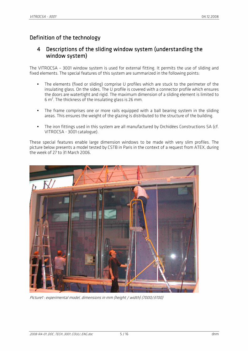
These special features enable large dimension windows to be made with very slim profiles. The picture below presents a model tested by CSTB in Paris in the context of a request from ATEX, during the week of 27 to 31 March 2006.
Picture1 : experimental model, dimensions in mm (height / width) (7000/3700)
VITROCSA - 3001 04.12.2008
2008-RA-01_DOC_TECH_3001_COULI_ENG.doc 6 / 16 dnm
4.14.14.14.1 General principle, specifications and field of applicationGeneral principle, specifications and field of applicationGeneral principle, specifications and field of applicationGeneral principle, specifications and field of application
Sliding elements (fixed)Sliding elements (fixed)Sliding elements (fixed)Sliding elements (fixed) VITROCSA – 3001 windows are intended to be used in facades but can also be used inside the building. By virtue of its constitution, VITROCSA – 3001 window applications are extremely flexible and exist in a variety of sliding configurations. Closing elementsClosing elementsClosing elementsClosing elements There is a very wide variety of locking options, defined together with the person in charge of the project. The most common type of locking system is the closing button (cf. VITROCSA - 3001 profiles drawing). Orchidées Constructions SA also supplies locking systems which comply with the WK2 burglar resistance requirements. Insulating glassInsulating glassInsulating glassInsulating glass The insulating glass used in VITROCSA – 3001 glazing has a total thickness of 26 mm. Thicknesses and the type of glass sheets (Float, ESG or VSG) are defined in accordance with the dimensions and requirements of the project. The thermal performances of the glass (type of gas, film) are defined by the person in charge of the project. Draining chamberDraining chamberDraining chamberDraining chamber Draining the frame is carried out vertically and rain water is collected in a stainless steel chamber. This is equipped with a draining foam which reduces the pressure of the wind. The chamber also contains PVC weight-bearing elements which distribute the forces (dead load) of the glazing to the concrete structure.
VITROCSA - 3001 04.12.2008
2008-RA-01_DOC_TECH_3001_COULI_ENG.doc 7 / 16 dnm
4.24.24.24.2 Definition of window componentsDefinition of window componentsDefinition of window componentsDefinition of window components
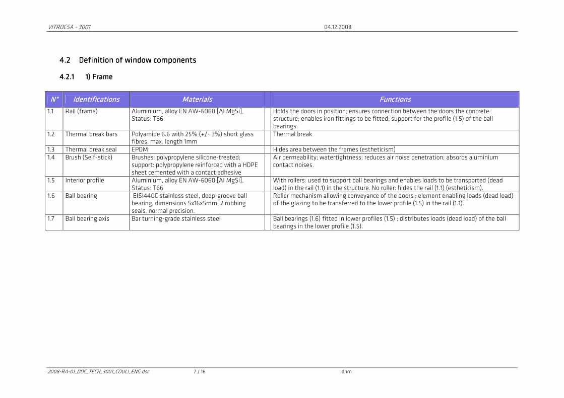
4.2.14.2.14.2.14.2.1 1) Frame 1) Frame 1) Frame 1) Frame
N°N°N°N° IdentificationsIdentificationsIdentificationsIdentifications MaterialsMaterialsMaterialsMaterials FunctionsFunctionsFunctionsFunctions
1.1 Rail (frame) Aluminium, alloy EN AW-6060 [AI MgSi], Status: T66
Holds the doors in position; ensures connection between the doors the concrete structure; enables iron fittings to be fitted; support for the profile (1.5) of the ball bearings.
1.2 Thermal break bars Polyamide 6.6 with 25% (+/- 3%) short glass fibres, max. length 1mm
Thermal break
1.3 Thermal break seal EPDM Hides area between the frames (estheticism) 1.4 Brush (Self-stick) Brushes: polypropylene silicone-treated;
support: polypropylene reinforced with a HDPE sheet cemented with a contact adhesive
Air permeability; watertightness; reduces air noise penetration; absorbs aluminium contact noises.
1.5 Interior profile Aluminium, alloy EN AW-6060 [AI MgSi], Status: T66
With rollers: used to support ball bearings and enables loads to be transported (dead load) in the rail (1.1) in the structure. No roller: hides the rail (1.1) (estheticism).
1.6 Ball bearing EISI440C stainless steel, deep-groove ball bearing, dimensions 5x16x5mm, 2 rubbing seals, normal precision.
Roller mechanism allowing conveyance of the doors ; element enabling loads (dead load) of the glazing to be transferred to the lower profile (1.5) in the rail (1.1).
1.7 Ball bearing axis Bar turning-grade stainless steel Ball bearings (1.6) fitted in lower profiles (1.5) ; distributes loads (dead load) of the ball bearings in the lower profile (1.5).
VITROCSA - 3001 04.12.2008
2008-RA-01_DOC_TECH_3001_COULI_ENG.doc 8 / 16 dnm
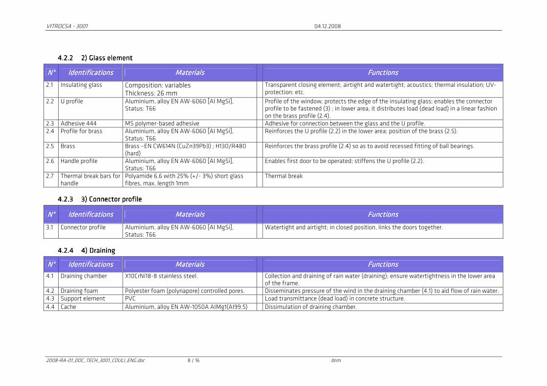
4.2.24.2.24.2.24.2.2 2) Glass element2) Glass element2) Glass element2) Glass element
N°N°N°N° IdentificationsIdentificationsIdentificationsIdentifications MaterialsMaterialsMaterialsMaterials FunctionsFunctionsFunctionsFunctions
2.1 Insulating glass Composition: variables Thickness: 26 mm
Transparent closing element; airtight and watertight; acoustics; thermal insulation; UV-protection; etc.
2.2 U profile Aluminium, alloy EN AW-6060 [AI MgSi], Status: T66
Profile of the window; protects the edge of the insulating glass; enables the connector profile to be fastened (3) ; in lower area, it distributes load (dead load) in a linear fashion on the brass profile (2.4).
2.3 Adhesive 444 MS polymer-based adhesive Adhesive for connection between the glass and the U profile. 2.4 Profile for brass Aluminium, alloy EN AW-6060 [AI MgSi],
Status: T66 Reinforces the U profile (2.2) in the lower area; position of the brass (2.5).
2.5 Brass Brass –EN CW614N (CuZn39Pb3) ; H130/R480 (hard)
Reinforces the brass profile (2.4) so as to avoid recessed fitting of ball bearings.
2.6 Handle profile Aluminium, alloy EN AW-6060 [AI MgSi], Status: T66
Enables first door to be operated; stiffens the U profile (2.2).
2.7 Thermal break bars for handle
Polyamide 6.6 with 25% (+/- 3%) short glass fibres, max. length 1mm
Thermal break
4.2.34.2.34.2.34.2.3 3) Connector profile3) Connector profile3) Connector profile3) Connector profile
N°N°N°N° IdeIdeIdeIdentificationsntificationsntificationsntifications MaterialsMaterialsMaterialsMaterials FunctionsFunctionsFunctionsFunctions
3.1 Connector profile Aluminium, alloy EN AW-6060 [AI MgSi], Status: T66
Watertight and airtight; in closed position, links the doors together.
4.2.44.2.44.2.44.2.4 4) Draining4) Draining4) Draining4) Draining
N°N°N°N° IdentificationsIdentificationsIdentificationsIdentifications MaterialsMaterialsMaterialsMaterials FunctionsFunctionsFunctionsFunctions
4.1 Draining chamber X10CrNi18-8 stainless steel. Collection and draining of rain water (draining); ensure watertightness in the lower area of the frame.
4.2 Draining foam Polyester foam (polynapore) controlled pores. Disseminates pressure of the wind in the draining chamber (4.1) to aid flow of rain water. 4.3 Support element PVC Load transmittance (dead load) in concrete structure.
4.4 Cache Aluminium, alloy EN AW-1050A AIMg1(AI99.5) Dissimulation of draining chamber.
VITROCSA - 3001 04.12.2008
2008-RA-01_DOC_TECH_3001_COULI_ENG.doc 9 / 16 dnm
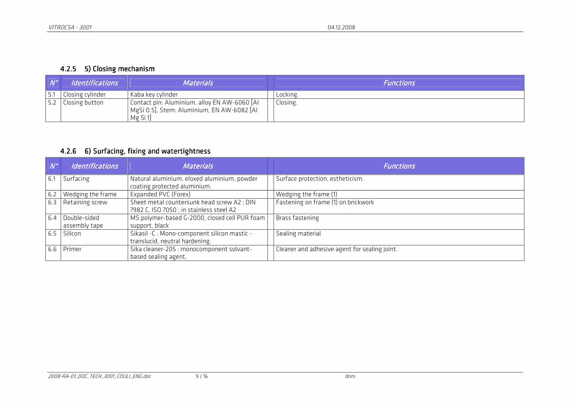
4.2.54.2.54.2.54.2.5 5) Closing mechanism5) Closing mechanism5) Closing mechanism5) Closing mechanism
N°N°N°N° IdentificationsIdentificationsIdentificationsIdentifications MaterialsMaterialsMaterialsMaterials FunctionsFunctionsFunctionsFunctions
5.1 Closing cylinder Kaba key cylinder Locking. 5.2 Closing button Contact pin: Aluminium, alloy EN AW-6060 [AI
MgSi 0.5], Stem: Aluminium, EN AW-6082 [AI Mg Si 1]
Closing.
4.2.64.2.64.2.64.2.6 6) Surfacing, fixing and watertightness6) Surfacing, fixing and watertightness6) Surfacing, fixing and watertightness6) Surfacing, fixing and watertightness
N°N°N°N° IdentificationsIdentificationsIdentificationsIdentifications MateMateMateMaterialsrialsrialsrials FunctionsFunctionsFunctionsFunctions
6.1 Surfacing Natural aluminium, eloxed aluminium, powder coating protected aluminium.
Surface protection, estheticism.
6.2 Wedging the frame Expanded PVC (Forex) Wedging the frame (1) 6.3 Retaining screw Sheet metal countersunk head screw A2 ; DIN
7982 C, ISO 7050 ; in stainless steel A2 Fastening on frame (1) on brickwork
6.4 Double-sided assembly tape
MS polymer-based G-2000, closed cell PUR foam support, black
Brass fastening
6.5 Silicon Sikasil -C : Mono-component silicon mastic - translucid, neutral hardening.
Sealing material
6.6 Primer Sika cleaner-205 : monocomponent solvant-based sealing agent.
Cleaner and adhesive agent for sealing joint.
VITROCSA - 3001 04.12.2008
2008-RA-01_DOC_TECH_3001_COULI_ENG.doc 10 / 16 dnm
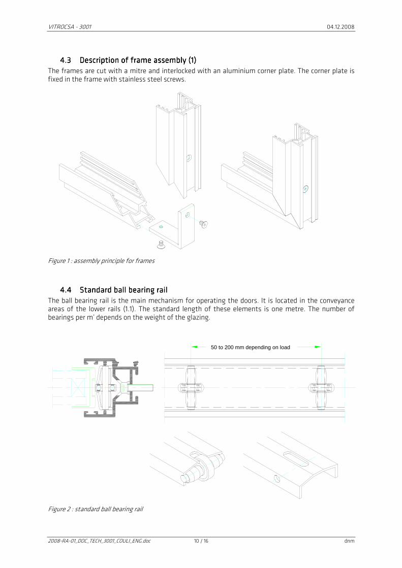
4.34.34.34.3 Description of frame assembly (1)Description of frame assembly (1)Description of frame assembly (1)Description of frame assembly (1)
The frames are cut with a mitre and interlocked with an aluminium corner plate. The corner plate is fixed in the frame with stainless steel screws.
Figure 1 : assembly principle for frames
4.44.44.44.4 Standard ball bearing rail Standard ball bearing rail Standard ball bearing rail Standard ball bearing rail
The ball bearing rail is the main mechanism for operating the doors. It is located in the conveyance areas of the lower rails (1.1). The standard length of these elements is one metre. The number of bearings per m’ depends on the weight of the glazing.
Figure 2 : standard ball bearing rail
50 to 200 mm depending on load
VITROCSA - 3001 04.12.2008
2008-RA-01_DOC_TECH_3001_COULI_ENG.doc 11 / 16 dnm
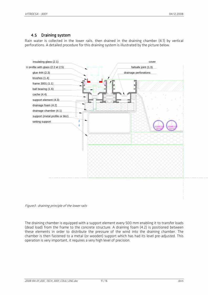
4.54.54.54.5 Draining systemDraining systemDraining systemDraining system
Rain water is collected in the lower rails, then drained in the draining chamber (4.1) by vertical perforations. A detailed procedure for this draining system is illustrated by the picture below.
Figure3 : draining principle of the lower rails The draining chamber is equipped with a support element every 500 mm enabling it to transfer loads (dead load) from the frame to the concrete structure. A draining foam (4.2) is positioned between these elements in order to distribute the pressure of the wind into the draining chamber. The chamber is then fastened to a metal (or wooden) support which has had its level pre-adjusted. This operation is very important, it requires a very high level of precision.
insulating glass (2.1)
U profile with glass (2.2 et 2.5)
glue 444 (2.3)
brushes (1.4)
frame 3001 (1.1)
ball bearing (1.6)
cache (4.4)
cover
failsafe joint (1.3)
drainage perforations
support element (4.3)
drainage foam (4.2)
drainage chamber (4.1)
support (metal profile or blcr)
setting support
UNDERFLOOR
HEATING
UNDERFLOOR
HEATING
VITROCSA - 3001 04.12.2008
2008-RA-01_DOC_TECH_3001_COULI_ENG.doc 12 / 16 dnm
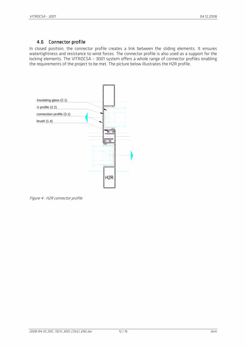
4.64.64.64.6 Connector profileConnector profileConnector profileConnector profile
In closed position, the connector profile creates a link between the sliding elements. It ensures watertightness and resistance to wind forces. The connector profile is also used as a support for the locking elements. The VITROCSA – 3001 system offers a whole range of connector profiles enabling the requirements of the project to be met. The picture below illustrates the H2R profile.
Figure 4 : H2R connector profile
H2R
insulating glass (2.1)
U profile (2.2)
connection profile (3.1)
brush (1.4)

VITROCSA - 3001 04.12.2008
2008-RA-01_DOC_TECH_3001_COULI_ENG.doc 13 / 16 dnm
Justifications Justifications Justifications Justifications
5555 Reliability and preserving over timeReliability and preserving over timeReliability and preserving over timeReliability and preserving over time The first VITROCSA – 3001 window was developed at the start of the Nineties. With our current experience, we can confirm that this system presents no hidden defect. The sliding mechanism and the watertightness system operates perfectly on condition the window is installed professionally. In order to demonstrate consistent operation of the VITROCSA - 3001 window, we have run standardized tests in an accredited laboratory (SERVICE SUISSE D’ESSAI STS 317). The results of these experiments are presented in the following table:
Type of testsType of testsType of testsType of tests Standards (test and classification)Standards (test and classification)Standards (test and classification)Standards (test and classification) ClassificationClassificationClassificationClassification
Air permeability EN 1026 (test) EN12207 (classification)
Class 4
Watertightness EN 1027 (test) EN12208 (classification)
Class 7A
Repeated opening and closing EN 1191 (test) EN 12400 (classification)
Class 3 (20 000 cycles)
Resistance to racking EN 14608 (test) EN 13115 (classification)
Class 3 (600 N)
Burglar resistance EN 1628 to 1630 (test) EN 1630 (classification)
WK2 (resistance class 2)
Test element: fixedTest element: fixedTest element: fixedTest element: fixed----sliding approx. dimension 2500/2500 mmsliding approx. dimension 2500/2500 mmsliding approx. dimension 2500/2500 mmsliding approx. dimension 2500/2500 mm
Table 1 : standardized tests done on VITROCSA - 3001 window
6666 Static dimensioningStatic dimensioningStatic dimensioningStatic dimensioning The dimensioning of connector profiles is carried out based on the local wind pressures. These pressures are defined using construction standards (Eurocode, SIA 261, NV 65, etc.). E.g. for a site in Monaco, the wind load is determined as follows:
• The on-site wind pressure is described in the NV 65 (04/2000) standard with the assumptions: zone 2, exposed site.
• qv = 0.6 * 1.3 = 0.78 [kN/m2]
• ChoiceChoiceChoiceChoice: qv = 0.8 [kN/m2] Using this indication, Orchidées Constructions SA engineers determine the dimensioning of the glazing. The maximum deflection of the VITROCSA – 3001 window is limited to the following value:
mm15w;150
Lw maxmax
L : length of connector profile in mm. The maximum dimensioning stress of the VITROCSA – 3001 profiles (in aluminium) is limited to 120 N/mm2.
VITROCSA - 3001 04.12.2008
2008-RA-01_DOC_TECH_3001_COULI_ENG.doc 14 / 16 dnm
7777 Calculating the thermal transCalculating the thermal transCalculating the thermal transCalculating the thermal transmittance Umittance Umittance Umittance Uwwww of a VITROCSA of a VITROCSA of a VITROCSA of a VITROCSA ---- 3001 3001 3001 3001 windowwindowwindowwindow
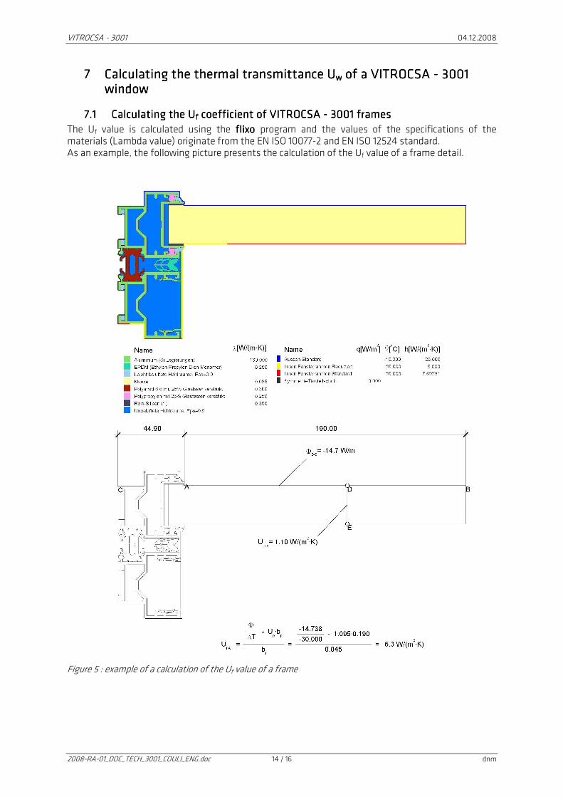
7.17.17.17.1 Calculating the UCalculating the UCalculating the UCalculating the Uffff coefficient of VITROCSA coefficient of VITROCSA coefficient of VITROCSA coefficient of VITROCSA ---- 3001 frames 3001 frames 3001 frames 3001 frames
The Uf value is calculated using the flixo flixo flixo flixo program and the values of the specifications of the materials (Lambda value) originate from the EN ISO 10077-2 and EN ISO 12524 standard. As an example, the following picture presents the calculation of the Uf value of a frame detail.
Figure 5 : example of a calculation of the Uf value of a frame
VITROCSA - 3001 04.12.2008
2008-RA-01_DOC_TECH_3001_COULI_ENG.doc 15 / 16 dnm
7.27.27.27.2 Calculating the UCalculating the UCalculating the UCalculating the Uwwww value of the window value of the window value of the window value of the window
The thermal transmittance Uw value of the window is calculated using the following variables:
• Dimensions of the window.
• Surface of the frame projected in the light void of the brickwork.
• Thermal transmittance coefficient of the Ug glazing [W/(m2K)].
• Thermal transmittance coefficient of the Ufm frame [W/(m2K)].
• Linear transmittance coefficient of the glazing [W/(mK)]. This way, the Uw value of the window depends on the different variables specific to this project. As a result, engineers from Orchidées Constructions SA calculate the Uw values on a case by case basis based on the requirements of the project.
General ProvisionsGeneral ProvisionsGeneral ProvisionsGeneral Provisions This report is classified: CONFIDENTIAL This report may not be reproduced, whole or in part, without authorization from Orchidées Constructions SA. Any publication of the report, whole or in part, is subject to prior written authorization from Orchidées Constructions SA.
7.37.37.37.3 Contents of reportContents of reportContents of reportContents of report
This report comprises 16 pages, annexes included. Onnens, 15th October 2008
VITROCSA - 3001 04.12.2008
2008-RA-01_DOC_TECH_3001_COULI_ENG.doc 16 / 16 dnm
IllustrationsIllustrationsIllustrationsIllustrations
8888 PiPiPiPicturescturescturesctures Picture1 : experimental model, dimensions in mm (height / width) (7000/3700) ............................. 5
9999 FiguresFiguresFiguresFigures Figure 1 : assembly principle for frames .....................................................................................10 Figure 2 : standard ball bearing rail ...........................................................................................10 Figure 3 : draining principle of the lower rails..............................................................................11 Figure 4 : H2R connector profile................................................................................................12 Figure 5 : example of a calculation of the Uf value of a frame .......................................................14
10101010 TablesTablesTablesTables Table 1 : standardized tests done on VITROCSA - 3001 window ....................................................13