Embed Size (px)
Citation preview
Seats and Restraint System ............................. 1-1Front Seats ............................................... 1-2Rear Seats .............................................. 1-11Safety Belts ............................................. 1-13Child Restraints ....................................... 1-32Airbag System ......................................... 1-55Restraint System Check ............................ 1-70
Features and Controls ..................................... 2-1Keys ........................................................ 2-3Doors and Locks ....................................... 2-7Windows ................................................. 2-14Theft-Deterrent Systems ............................ 2-17Starting and Operating Your Vehicle ........... 2-21Mirrors .................................................... 2-40OnStar® System ...................................... 2-45Universal Home Remote System ................ 2-48Storage Areas ......................................... 2-53Sunroof .................................................. 2-57
Instrument Panel ............................................. 3-1Instrument Panel Overview .......................... 3-4Climate Controls ...................................... 3-20Warning Lights, Gages, and Indicators ........ 3-28Driver Information Center (DIC) .................. 3-47Audio System(s) ....................................... 3-62
Driving Your Vehicle ....................................... 4-1Your Driving, the Road, and the Vehicle ....... 4-2Towing ................................................... 4-40
Service and Appearance Care .......................... 5-1Service ..................................................... 5-3Fuel ......................................................... 5-5Checking Things Under the Hood ............... 5-10All-Wheel Drive ........................................ 5-48Rear Axle ............................................... 5-49Four-Wheel Drive ..................................... 5-50Front Axle ............................................... 5-51Headlamp Aiming ..................................... 5-52Bulb Replacement .................................... 5-52Windshield Wiper Blade Replacement ......... 5-55Tires ...................................................... 5-58Appearance Care ................................... 5-109Vehicle Identification ............................... 5-117Electrical System .................................... 5-118Capacities and Specifications ................... 5-125
Maintenance Schedule ..................................... 6-1Maintenance Schedule ................................ 6-2
Customer Assistance Information .................... 7-1Customer Assistance and Information ........... 7-2Reporting Safety Defects ........................... 7-15Vehicle Data Recording and Privacy ........... 7-17
Index ................................................................ 1
2009 Chevrolet TrailBlazer Owner Manual M
GENERAL MOTORS, GM, the GM Emblem,CHEVROLET, the CHEVROLET Emblem, and thename TRAILBLAZER are registered trademarksof General Motors Corporation.
This manual includes the latest information at the time itwas printed. GM reserves the right to make changes afterthat time without further notice. For vehicles first sold inCanada, substitute the name “General Motors of CanadaLimited” for Chevrolet Motor Division wherever it appearsin this manual.
This manual describes features that may or may not beon your specific vehicle.
Read this manual from beginning to end to learn aboutthe vehicle’s features and controls. Pictures, symbols,and words work together to explain vehicle operation.
Keep this manual in the vehicle for quick reference.
Canadian OwnersA French language copy of this manual can be obtainedfrom your dealer/retailer or from:
Helm, IncorporatedP.O. Box 07130Detroit, MI 48207
1-800-551-4123helminc.com
Propriétaires CanadiensOn peut obtenir un exemplaire de ce guide en françaisauprès de concessionnaire ou à l’adresse suivante:
Helm IncorporatedP.O. Box 07130Detroit, MI 48207
1-800-551-4123helminc.com
IndexTo quickly locate information about the vehicle use theIndex in the back of the manual. It is an alphabeticallist of what is in the manual and the page number whereit can be found.
Litho in U.S.A.Part No. 25820780 A First Printing ©2008 General Motors Corporation. All Rights Reserved.
ii

Safety Warnings and Symbols
A circle with a slashthrough it is a safetysymbol which means“Do Not,” “Do not do this” or“Do not let this happen.”
A box with the word CAUTION is used to tell aboutthings that could hurt you or others if you were to ignorethe warning.
{CAUTION:
These mean there is something that could hurtyou or other people.
Cautions tell what the hazard is and what to do to avoidor reduce the hazard. Read these cautions.
A notice tells about something that can damage thevehicle.
Notice: These mean there is something that coulddamage your vehicle.
Many times, this damage would not be covered by thevehicle’s warranty, and it could be costly. The noticetells what to do to help avoid the damage.
There are also warning labels on the vehicle which usethe same words, CAUTION or Notice.
iii

Vehicle SymbolsThe vehicle has components and labels that usesymbols instead of text. Symbols are shown alongwith the text describing the operation or informationrelating to a specific component, control, message,gage, or indicator.
M : This symbol is shown when you need to see yourowner manual for additional instructions or information.
* : This symbol is shown when you need to see aservice manual for additional instructions or information.
Vehicle Symbol ChartHere are some additional symbols that may be found onthe vehicle and what they mean. For more informationon the symbol, refer to the index.
0 : Adjustable Pedals
9 : Airbag Readiness Light
# : Air Conditioning
! : Antilock Brake System (ABS)
g : Audio Steering Wheel Controls or OnStar®
$ : Brake System Warning Light
" : Charging System
I : Cruise Control
B : Engine Coolant Temperature
O : Exterior Lamps
# : Fog Lamps
. : Fuel Gage
+ : Fuses
i : Headlamp High/Low-Beam Changer
j : LATCH System Child Restraints
* : Malfunction Indicator Lamp
: : Oil Pressure
} : Power
/ : Remote Vehicle Start
> : Safety Belt Reminders
7 : Tire Pressure Monitor
F : Traction Control
M : Windshield Washer Fluid
iv

Front Seats ......................................................1-2Manual Seats ................................................1-2Power Seats ..................................................1-3Manual Lumbar ..............................................1-3Power Lumbar ...............................................1-4Heated Seats .................................................1-4Memory Seat .................................................1-5Reclining Seatbacks ........................................1-7Head Restraints ............................................1-10
Rear Seats .....................................................1-11Rear Seat Operation .....................................1-11
Safety Belts ...................................................1-13Safety Belts: They Are for Everyone ................1-13How to Wear Safety Belts Properly .................1-18Lap-Shoulder Belt .........................................1-27Safety Belt Use During Pregnancy ..................1-31Safety Belt Extender .....................................1-32
Child Restraints .............................................1-32Older Children ..............................................1-32Infants and Young Children ............................1-35Child Restraint Systems .................................1-39Where to Put the Restraint .............................1-42
Lower Anchors and Tethers forChildren (LATCH) ......................................1-43
Securing a Child Restraint in aRear Outside Seat Position .........................1-49
Securing a Child Restraint in theCenter Rear Seat Position ..........................1-51
Securing a Child Restraint in theRight Front Seat Position ............................1-52
Airbag System ...............................................1-55Where Are the Airbags? ................................1-58When Should an Airbag Inflate? .....................1-60What Makes an Airbag Inflate? .......................1-61How Does an Airbag Restrain? .......................1-61What Will You See After an Airbag Inflates? .....1-62Passenger Sensing System ............................1-63Servicing Your Airbag-Equipped Vehicle ...........1-68Adding Equipment to Your
Airbag-Equipped Vehicle .............................1-68Restraint System Check ..................................1-70
Checking the Restraint Systems ......................1-70Replacing Restraint System Parts
After a Crash ............................................1-71
Section 1 Seats and Restraint System
1-1
Front Seats
Manual Seats
{CAUTION:
You can lose control of the vehicle if you try toadjust a manual driver’s seat while the vehicle ismoving. The sudden movement could startle andconfuse you, or make you push a pedal when youdo not want to. Adjust the driver’s seat only whenthe vehicle is not moving.
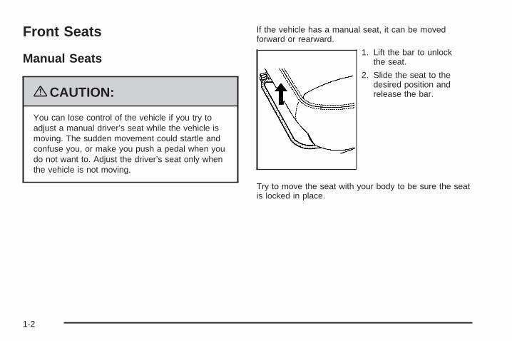
If the vehicle has a manual seat, it can be movedforward or rearward.
1. Lift the bar to unlockthe seat.
2. Slide the seat to thedesired position andrelease the bar.
Try to move the seat with your body to be sure the seatis locked in place.
1-2
Power Seats
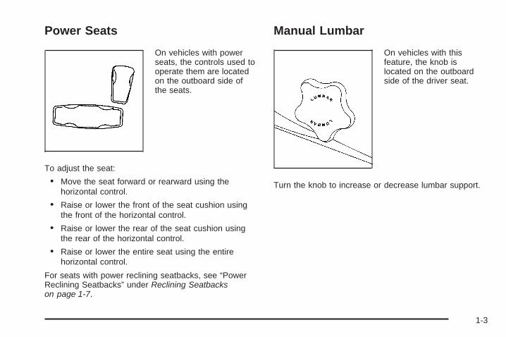
On vehicles with powerseats, the controls used tooperate them are locatedon the outboard side ofthe seats.
To adjust the seat:
• Move the seat forward or rearward using thehorizontal control.
• Raise or lower the front of the seat cushion usingthe front of the horizontal control.
• Raise or lower the rear of the seat cushion usingthe rear of the horizontal control.
• Raise or lower the entire seat using the entirehorizontal control.
For seats with power reclining seatbacks, see “PowerReclining Seatbacks” under Reclining Seatbackson page 1-7.
Manual Lumbar
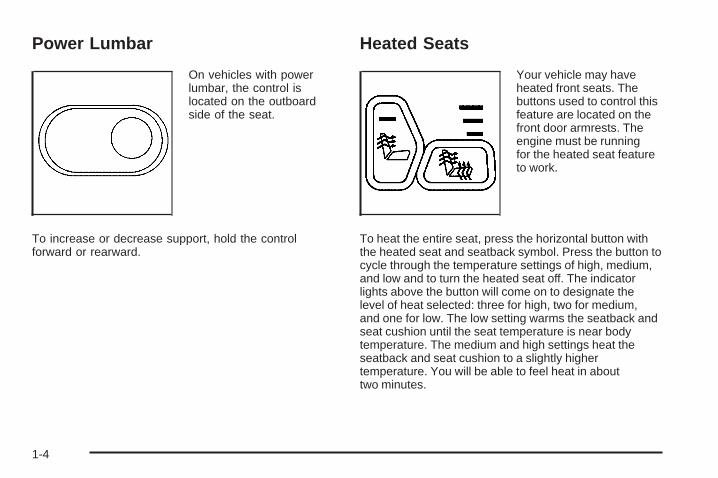
On vehicles with thisfeature, the knob islocated on the outboardside of the driver seat.
Turn the knob to increase or decrease lumbar support.
1-3
Power Lumbar
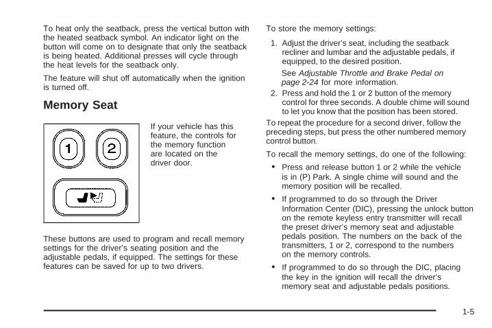
On vehicles with powerlumbar, the control islocated on the outboardside of the seat.
To increase or decrease support, hold the controlforward or rearward.
Heated Seats
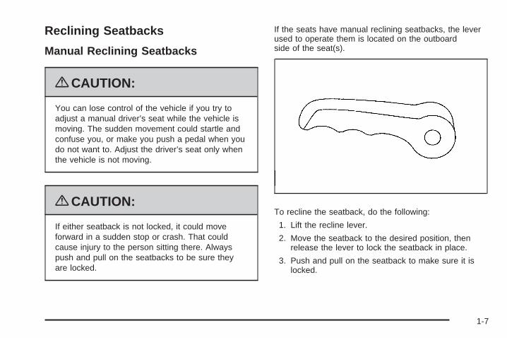
Your vehicle may haveheated front seats. Thebuttons used to control thisfeature are located on thefront door armrests. Theengine must be runningfor the heated seat featureto work.
To heat the entire seat, press the horizontal button withthe heated seat and seatback symbol. Press the button tocycle through the temperature settings of high, medium,and low and to turn the heated seat off. The indicatorlights above the button will come on to designate thelevel of heat selected: three for high, two for medium,and one for low. The low setting warms the seatback andseat cushion until the seat temperature is near bodytemperature. The medium and high settings heat theseatback and seat cushion to a slightly highertemperature. You will be able to feel heat in abouttwo minutes.
1-4
To heat only the seatback, press the vertical button withthe heated seatback symbol. An indicator light on thebutton will come on to designate that only the seatbackis being heated. Additional presses will cycle throughthe heat levels for the seatback only.
The feature will shut off automatically when the ignitionis turned off.
Memory Seat
If your vehicle has thisfeature, the controls forthe memory functionare located on thedriver door.
These buttons are used to program and recall memorysettings for the driver’s seating position and theadjustable pedals, if equipped. The settings for thesefeatures can be saved for up to two drivers.
To store the memory settings:
1. Adjust the driver’s seat, including the seatbackrecliner and lumbar and the adjustable pedals, ifequipped, to the desired position.See Adjustable Throttle and Brake Pedal onpage 2-24 for more information.
2. Press and hold the 1 or 2 button of the memorycontrol for three seconds. A double chime will soundto let you know that the position has been stored.
To repeat the procedure for a second driver, follow thepreceding steps, but press the other numbered memorycontrol button.
To recall the memory settings, do one of the following:
• Press and release button 1 or 2 while the vehicleis in (P) Park. A single chime will sound and thememory position will be recalled.
• If programmed to do so through the DriverInformation Center (DIC), pressing the unlock buttonon the remote keyless entry transmitter will recallthe preset driver’s memory seat and adjustablepedals position. The numbers on the back of thetransmitters, 1 or 2, correspond to the numberson the memory controls.
• If programmed to do so through the DIC, placingthe key in the ignition will recall the driver’smemory seat and adjustable pedals positions.
1-5

See “Seat Recall” under DIC Vehicle Customization onpage 3-56 for more information.
To stop recall movement of the memory seat feature atany time, press one of the memory buttons or powerseat controls.
Easy Exit SeatThe control for the easy exit seat function is located onthe driver’s door below the memory buttons 1 and 2.The easy exit seat button is used to program and recallthe desired driver’s seat position when exiting or enteringthe vehicle. The power lumbar, recline, and adjustablepedals, if equipped, positions will not be stored orrecalled when using the easy exit seat function.The seat position can be saved for up to two drivers.
To store the easy exit seat position:
1. Press and release the 1 or 2 button of the memorycontrol for less than three seconds. The seat willmove to the stored memory position.
2. Adjust the seat to the desired exit position.
3. Press and hold the easy exit seat button for morethan three seconds. A double chime will sound tolet you know that the position has been storedfor the selected button 1 or 2.
To repeat the procedure for a second driver, followthe preceding steps, but press the other numberedmemory control button.
To recall the easy exit seat position:
• Press the easy exit seat button on the memorycontrol while the vehicle is in (P) Park. The seatwill move to the stored exit position.
• Or, if the easy exit seat feature is activated in theDriver Information Center (DIC), removing the keyfrom the ignition will move the seat to the exitposition. See “Easy Exit Seat” under DIC VehicleCustomization on page 3-56 for more informationon activating this feature in the DIC.
If an easy exit seat position has not been stored, thedefault position is all the way rearward.
1-6
Reclining Seatbacks
Manual Reclining Seatbacks
{CAUTION:
You can lose control of the vehicle if you try toadjust a manual driver’s seat while the vehicle ismoving. The sudden movement could startle andconfuse you, or make you push a pedal when youdo not want to. Adjust the driver’s seat only whenthe vehicle is not moving.
{CAUTION:
If either seatback is not locked, it could moveforward in a sudden stop or crash. That couldcause injury to the person sitting there. Alwayspush and pull on the seatbacks to be sure theyare locked.
If the seats have manual reclining seatbacks, the leverused to operate them is located on the outboardside of the seat(s).
To recline the seatback, do the following:
1. Lift the recline lever.
2. Move the seatback to the desired position, thenrelease the lever to lock the seatback in place.
3. Push and pull on the seatback to make sure it islocked.
1-7

To return the seatback to an upright position, do thefollowing:
1. Lift the lever fully without applying pressure to theseatback and the seatback will return to the uprightposition.
2. Push and pull on the seatback to make sure it islocked.
Power Reclining Seatbacks
If your seats have powerreclining seatbacks, usethe vertical power seatcontrol located on theoutboard side of theseat(s).
• To recline the seatback, press the control toward therear of the vehicle.
• To raise the seatback, press the control toward thefront of the vehicle.
1-8
{CAUTION:
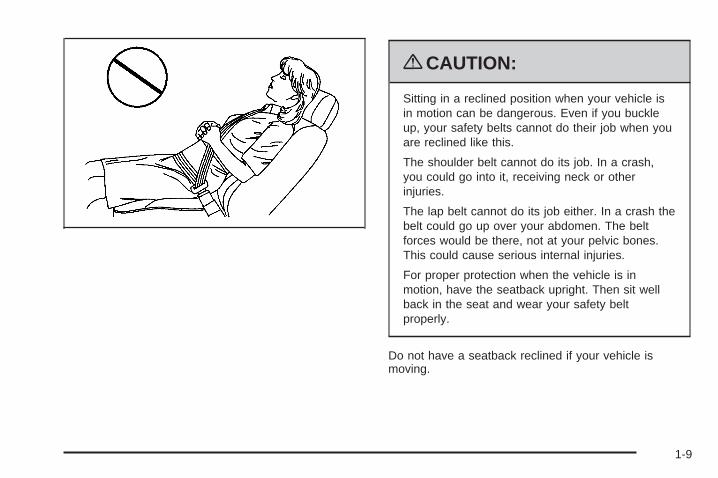
Sitting in a reclined position when your vehicle isin motion can be dangerous. Even if you buckleup, your safety belts cannot do their job when youare reclined like this.
The shoulder belt cannot do its job. In a crash,you could go into it, receiving neck or otherinjuries.
The lap belt cannot do its job either. In a crash thebelt could go up over your abdomen. The beltforces would be there, not at your pelvic bones.This could cause serious internal injuries.
For proper protection when the vehicle is inmotion, have the seatback upright. Then sit wellback in the seat and wear your safety beltproperly.
Do not have a seatback reclined if your vehicle ismoving.
1-9

Head Restraints
Adjust the head restraint so that the top of the restraintis at the same height as the top of the occupant’shead. This position reduces the chance of a neck injuryin a crash.
Pull the head restraint upto raise it.
To lower the head restraint, press the button, locatedon the top of the seatback, and push the headrestraint down.
1-10

Rear Seats
Rear Seat OperationYour vehicle has flip and fold second row seats whichprovide additional cargo space.
To flip and fold the seat(s), do the following:
1. Pull up on the loop located where the seat cushionmeets the seatback and flip the seat cushionforward.
Notice: Folding a rear seat with the safety beltsstill fastened may cause damage to the seat orthe safety belts. Always unbuckle the safety beltsand return them to their normal stowed positionbefore folding a rear seat.
2. Lift the lever, locatedon the outboard sideof the seatback,and fold the seatbackforward.
The head restraint will automatically fold out of theway as the seatback is folded down.
1-11

To return the seat(s) to the original position, do thefollowing:
{CAUTION:
If either seatback is not locked, it could moveforward in a sudden stop or crash. That couldcause injury to the person sitting there. Alwayspush and pull on the seatbacks to be sure theyare locked.
1. Lift the seatback until it locks into the uprightposition. Push and pull on the seatback tomake sure it is locked. 2. Return the head restraints to the upright position by
reaching behind the seat and pulling it forward untilit locks into place. Push and pull on the headrestraint to make sure that it is locked.
3. Flip the seat cushion back into place.
1-12
Safety Belts
Safety Belts: They Are for EveryoneThis section of the manual describes how to usesafety belts properly. It also describes some things notto do with safety belts.
{CAUTION:
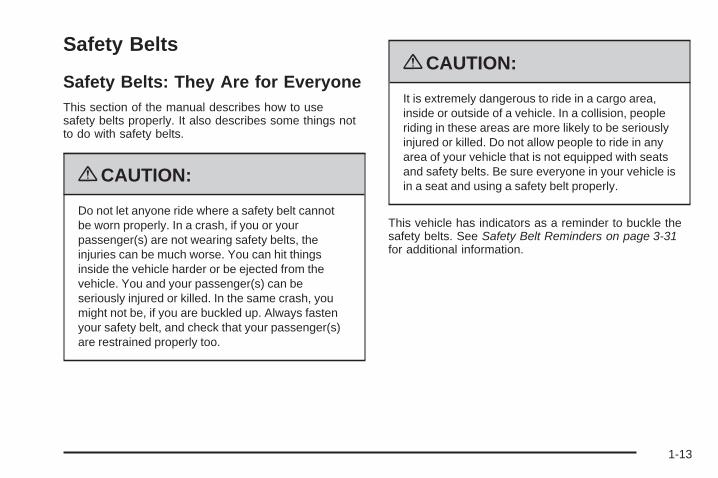
Do not let anyone ride where a safety belt cannotbe worn properly. In a crash, if you or yourpassenger(s) are not wearing safety belts, theinjuries can be much worse. You can hit thingsinside the vehicle harder or be ejected from thevehicle. You and your passenger(s) can beseriously injured or killed. In the same crash, youmight not be, if you are buckled up. Always fastenyour safety belt, and check that your passenger(s)are restrained properly too.
{CAUTION:
It is extremely dangerous to ride in a cargo area,inside or outside of a vehicle. In a collision, peopleriding in these areas are more likely to be seriouslyinjured or killed. Do not allow people to ride in anyarea of your vehicle that is not equipped with seatsand safety belts. Be sure everyone in your vehicle isin a seat and using a safety belt properly.
This vehicle has indicators as a reminder to buckle thesafety belts. See Safety Belt Reminders on page 3-31for additional information.
1-13

In most states and in all Canadian provinces, the lawrequires wearing safety belts. Here is why:
You never know if you will be in a crash. If you do havea crash, you do not know if it will be a serious one.
A few crashes are mild, and some crashes can beso serious that even buckled up, a person would notsurvive. But most crashes are in between. In manyof them, people who buckle up can survive andsometimes walk away. Without safety belts, theycould have been badly hurt or killed.
After more than 40 years of safety belts in vehicles,the facts are clear. In most crashes buckling up doesmatter... a lot!
Why Safety Belts WorkWhen you ride in or on anything, you go as fast asit goes.
Take the simplest vehicle. Suppose it is just a seat onwheels.
1-14
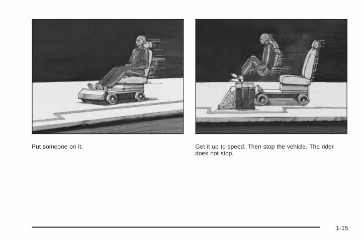
Put someone on it. Get it up to speed. Then stop the vehicle. The riderdoes not stop.
1-15

The person keeps going until stopped by something. Ina real vehicle, it could be the windshield...
or the instrument panel...
1-16
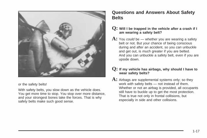
or the safety belts!
With safety belts, you slow down as the vehicle does.You get more time to stop. You stop over more distance,and your strongest bones take the forces. That is whysafety belts make such good sense.
Questions and Answers About SafetyBelts
Q: Will I be trapped in the vehicle after a crash if Iam wearing a safety belt?
A: You could be — whether you are wearing a safetybelt or not. But your chance of being consciousduring and after an accident, so you can unbuckleand get out, is much greater if you are belted.And you can unbuckle a safety belt, even if you areupside down.
Q: If my vehicle has airbags, why should I have towear safety belts?
A: Airbags are supplemental systems only; so theywork with safety belts — not instead of them.Whether or not an airbag is provided, all occupantsstill have to buckle up to get the most protection.That is true not only in frontal collisions, butespecially in side and other collisions.
1-17
Q: If I am a good driver, and I never drive far fromhome, why should I wear safety belts?
A: You may be an excellent driver, but if you are in acrash — even one that is not your fault — you andyour passenger(s) can be hurt. Being a good driverdoes not protect you from things beyond yourcontrol, such as bad drivers.
Most accidents occur within 25 miles (40 km) ofhome. And the greatest number of serious injuriesand deaths occur at speeds of less than 40 mph(65 km/h).
Safety belts are for everyone.
How to Wear Safety Belts ProperlyThis section is only for people of adult size.
Be aware that there are special things to know aboutsafety belts and children. And there are differentrules for smaller children and infants. If a child will beriding in the vehicle, see Older Children on page 1-32or Infants and Young Children on page 1-35. Followthose rules for everyone’s protection.
It is very important for all occupants to buckle up.Statistics show that unbelted people are hurt more oftenin crashes than those who are wearing safety belts.
Occupants who are not buckled up can be thrown out ofthe vehicle in a crash. And they can strike others inthe vehicle who are wearing safety belts.
First, before you or your passenger(s) wear a safetybelt, there is important information you should know.
1-18

Sit up straight and always keep your feet on the floor infront of you. The lap part of the belt should be wornlow and snug on the hips, just touching the thighs.
In a crash, this applies force to the strong pelvic bonesand you would be less likely to slide under the lapbelt. If you slid under it, the belt would apply force onyour abdomen. This could cause serious or evenfatal injuries. The shoulder belt should go over theshoulder and across the chest. These parts of thebody are best able to take belt restraining forces.
The shoulder belt locks if there is a sudden stop orcrash.
1-19

Q: What is wrong with this?
A: The shoulder belt is too loose. It will not give asmuch protection this way.
{CAUTION:
You can be seriously hurt if your shoulder belt istoo loose. In a crash, you would move forward toomuch, which could increase injury. The shoulderbelt should fit snugly against your body.
1-20

Q: What is wrong with this?
A: The lap belt is too loose. It will not give nearly asmuch protection this way.
{CAUTION:
You can be seriously hurt if your lap belt is tooloose. In a crash, you could slide under the lapbelt and apply force on your abdomen. This couldcause serious or even fatal injuries. The lap beltshould be worn low and snug on the hips, justtouching the thighs.
1-21
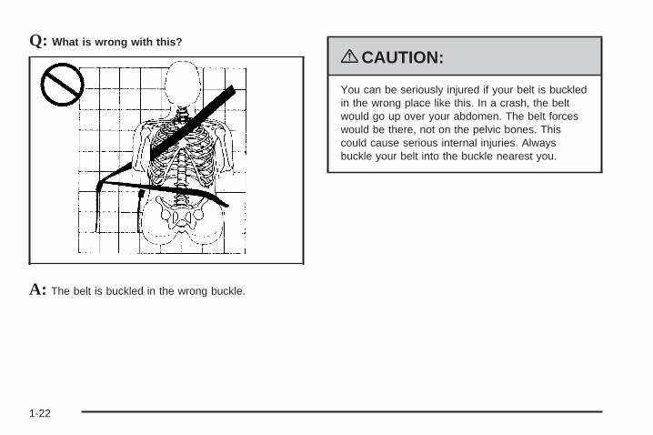
Q: What is wrong with this?
A: The belt is buckled in the wrong buckle.
{CAUTION:
You can be seriously injured if your belt is buckledin the wrong place like this. In a crash, the beltwould go up over your abdomen. The belt forceswould be there, not on the pelvic bones. Thiscould cause serious internal injuries. Alwaysbuckle your belt into the buckle nearest you.
1-22
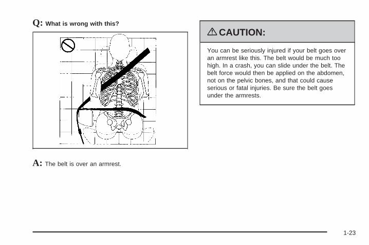
Q: What is wrong with this?
A: The belt is over an armrest.
{CAUTION:
You can be seriously injured if your belt goes overan armrest like this. The belt would be much toohigh. In a crash, you can slide under the belt. Thebelt force would then be applied on the abdomen,not on the pelvic bones, and that could causeserious or fatal injuries. Be sure the belt goesunder the armrests.
1-23

Q: What is wrong with this?
A: The shoulder belt is worn under the arm. It shouldbe worn over the shoulder at all times.
{CAUTION:
You can be seriously injured if you wear theshoulder belt under your arm. In a crash, yourbody would move too far forward, which wouldincrease the chance of head and neck injury. Also,the belt would apply too much force to the ribs,which are not as strong as shoulder bones. Youcould also severely injure internal organs like yourliver or spleen. The shoulder belt should go overthe shoulder and across the chest.
1-24

Q: What is wrong with this?
A: The belt is behind the body.
{CAUTION:
You can be seriously injured by not wearing thelap-shoulder belt properly. In a crash, you wouldnot be restrained by the shoulder belt. Your bodycould move too far forward increasing the chanceof head and neck injury. You might also slideunder the lap belt. The belt force would then beapplied right on the abdomen. That could causeserious or fatal injuries. The shoulder belt shouldgo over the shoulder and across the chest.
1-25
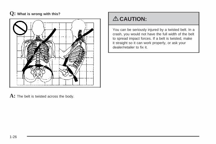
Q: What is wrong with this?
A: The belt is twisted across the body.
{CAUTION:
You can be seriously injured by a twisted belt. In acrash, you would not have the full width of the beltto spread impact forces. If a belt is twisted, makeit straight so it can work properly, or ask yourdealer/retailer to fix it.
1-26

Lap-Shoulder BeltAll seating positions in the vehicle have alap-shoulder belt.
The following instructions explain how to wear alap-shoulder belt properly.
1. Adjust the seat, if the seat is adjustable, so you cansit up straight. To see how, see “Seats” in the Index.
2. Pick up the latch plate and pull the belt across you.Do not let it get twisted.The lap-shoulder belt may lock if you pull the beltacross you very quickly. If this happens, let the beltgo back slightly to unlock it. Then pull the beltacross you more slowly.If you ever pull the shoulder portion of a passengerbelt out all the way, the child restraint lockingfeature may be engaged. If this happens, let thebelt go back all the way and start again.Engaging the child restraint locking feature in theright front seating position may affect the passengersensing system. See Passenger Sensing Systemon page 1-63 for more information.
3. Push the latch plate into the buckle until it clicks.Pull up on the latch plate to make sure it is secure.If the belt is not long enough, see Safety BeltExtender on page 1-32.Position the release button on the buckle so thatthe safety belt could be quickly unbuckled ifnecessary.
1-27

4. To make the lap part tight, pull up on theshoulder belt.It may be necessary to pull stitching on the safetybelt through the latch plate to fully tighten thelap belt on smaller occupants.
To unlatch the belt, push the button on the buckle.The belt should return to its stowed position.
Before a door is closed, be sure the safety belt is out ofthe way. If a door is slammed against a safety belt,damage can occur to both the belt and the vehicle.
1-28

Safety Belt PretensionersThis vehicle has safety belt pretensioners for thefront outboard occupants. Although the safety beltpretensioners cannot be seen, they are part of the safetybelt assembly. They can help tighten the safety beltsduring the early stages of a moderate to severe frontalor near frontal crash if the threshold conditions forpretensioner activation are met. And, if your vehicle hasside impact airbags, safety belt pretensioners can helptighten the safety belts in a side crash or a rollover event.
Pretensioners work only once. If the pretensionersactivate in a crash, they will need to be replaced,and probably other new parts for the vehicle’s safetybelt system. See Replacing Restraint System Parts Aftera Crash on page 1-71.
Rear Safety Belt Comfort GuidesRear shoulder belt comfort guides may provide addedsafety belt comfort for older children who have outgrownbooster seats and for some adults. When installed ona shoulder belt, the comfort guide positions the beltaway from the neck and head.
There is one guide for each outside passenger positionin the rear seat. Here is how to install the comfortguide to the shoulder belt:
1. Slide the guide off of its storage clip locatedbetween the interior body and the seatback or fromthe storage pocket on the side of the seat.
2. Place the guide over the belt and insert the twoedges of the belt into the slots of the guide.
1-29
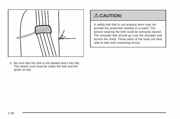
3. Be sure that the belt is not twisted and it lies flat.The elastic cord must be under the belt and theguide on top.
{CAUTION:
A safety belt that is not properly worn may notprovide the protection needed in a crash. Theperson wearing the belt could be seriously injured.The shoulder belt should go over the shoulder andacross the chest. These parts of the body are bestable to take belt restraining forces.
1-30
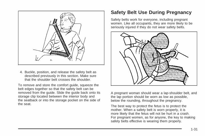
4. Buckle, position, and release the safety belt asdescribed previously in this section. Make surethat the shoulder belt crosses the shoulder.
To remove and store the comfort guide, squeeze thebelt edges together so that the safety belt can beremoved from the guide. Slide the guide back onto itsstorage clip located between the interior body andthe seatback or into the storage pocket on the side ofthe seat.
Safety Belt Use During PregnancySafety belts work for everyone, including pregnantwomen. Like all occupants, they are more likely to beseriously injured if they do not wear safety belts.
A pregnant woman should wear a lap-shoulder belt, andthe lap portion should be worn as low as possible,below the rounding, throughout the pregnancy.
The best way to protect the fetus is to protect themother. When a safety belt is worn properly, it ismore likely that the fetus will not be hurt in a crash.For pregnant women, as for anyone, the key to makingsafety belts effective is wearing them properly.
1-31

Safety Belt ExtenderIf the safety belt will fasten around you, you shoulduse it.
But if a safety belt is not long enough, your dealer/retailer will order you an extender. When you go in toorder it, take the heaviest coat you will wear, so theextender will be long enough for you. To help avoidpersonal injury, do not let someone else use it, and use itonly for the seat it is made to fit. The extender has beendesigned for adults. Never use it for securing child seats.To wear it, attach it to the regular safety belt. For moreinformation, see the instruction sheet that comes withthe extender.
Child Restraints
Older Children
Older children who have outgrown booster seats shouldwear the vehicle’s safety belts.
1-32

The manufacturer’s instructions that come with thebooster seat state the weight and height limitations forthat booster. Use a booster seat with a lap-shoulder beltuntil the child passes the below fit test:
• Sit all the way back on the seat. Do the knees bendat the seat edge? If yes, continue. If no, return tothe booster seat.
• Buckle the lap-shoulder belt. Does the shoulder beltrest on the shoulder? If yes, continue. If no, tryusing the rear safety belt comfort guide. See “RearSafety Belt Comfort Guides” under Lap-ShoulderBelt on page 1-27 for more information. If theshoulder belt still does not rest on the shoulder,then return to the booster seat.
• Does the lap belt fit low and snug on the hips,touching the thighs? If yes, continue. If no, return tothe booster seat.
• Can proper safety belt fit be maintained for thelength of the trip? If yes, continue. If no, returnto the booster seat.
• If you have the choice, a child should sit in aposition with a lap-shoulder belt and get theadditional restraint a shoulder belt can provide.
Q: What is the proper way to wear safety belts?
A: An older child should wear a lap-shoulder belt andget the additional restraint a shoulder belt canprovide. The shoulder belt should not cross the faceor neck. The lap belt should fit snugly below thehips, just touching the top of the thighs. This appliesbelt force to the child’s pelvic bones in a crash.It should never be worn over the abdomen, whichcould cause severe or even fatal internal injuries ina crash.
Also see “Rear Safety Belt Comfort Guides” underLap-Shoulder Belt on page 1-27.
According to accident statistics, children and infantsare safer when properly restrained in a child restraintsystem or infant restraint system secured in a rearseating position.
In a crash, children who are not buckled up can strikeother people who are buckled up, or can be thrownout of the vehicle. Older children need to use safetybelts properly.
1-33

{CAUTION:
Never do this.
Never allow two children to wear the same safetybelt. The safety belt can not properly spread theimpact forces. In a crash, the two children can becrushed together and seriously injured. A safetybelt must be used by only one person at a time.
{CAUTION:
Never do this.
Never allow a child to wear the safety belt with theshoulder belt behind their back. A child can beseriously injured by not wearing the lap-shoulderbelt properly. In a crash, the child would not berestrained by the shoulder belt. The child couldmove too far forward increasing the chance ofhead and neck injury. The child might also slideunder the lap belt. The belt force would then beapplied right on the abdomen. That could causeserious or fatal injuries. The shoulder belt shouldgo over the shoulder and across the chest.
1-34

Infants and Young ChildrenEveryone in a vehicle needs protection! This includesinfants and all other children. Neither the distancetraveled nor the age and size of the traveler changesthe need, for everyone, to use safety restraints. In fact,the law in every state in the United States and inevery Canadian province says children up to some agemust be restrained while in a vehicle.
{CAUTION:
Children can be seriously injured or strangled if ashoulder belt is wrapped around their neck andthe safety belt continues to tighten. Never leavechildren unattended in a vehicle and never allowchildren to play with the safety belts.
Airbags plus lap-shoulder belts offer protection for adultsand older children, but not for young children and infants.Neither the vehicle’s safety belt system nor its airbagsystem is designed for them. Every time infants andyoung children ride in vehicles, they should have theprotection provided by appropriate child restraints.
Children who are not restrained properly can strike otherpeople, or can be thrown out of the vehicle.
1-35
{CAUTION:
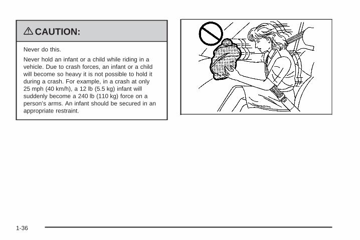
Never do this.
Never hold an infant or a child while riding in avehicle. Due to crash forces, an infant or a childwill become so heavy it is not possible to hold itduring a crash. For example, in a crash at only25 mph (40 km/h), a 12 lb (5.5 kg) infant willsuddenly become a 240 lb (110 kg) force on aperson’s arms. An infant should be secured in anappropriate restraint.
1-36

{CAUTION:
Never do this.
Children who are up against, or very close to, anyairbag when it inflates can be seriously injured orkilled. Never put a rear-facing child restraint in theright front seat. Secure a rear-facing child restraintin a rear seat. It is also better to secure aforward-facing child restraint in a rear seat. If youmust secure a forward-facing child restraint in theright front seat, always move the front passengerseat as far back as it will go.
1-37
Q: What are the different types of add-on childrestraints?
A: Add-on child restraints, which are purchased by thevehicle’s owner, are available in four basic types.Selection of a particular restraint should takeinto consideration not only the child’s weight, height,and age but also whether or not the restraint willbe compatible with the motor vehicle in which it willbe used.
For most basic types of child restraints, there aremany different models available. When purchasing achild restraint, be sure it is designed to be usedin a motor vehicle. If it is, the restraint will have alabel saying that it meets federal motor vehiclesafety standards.
The restraint manufacturer’s instructions that comewith the restraint state the weight and heightlimitations for a particular child restraint. In addition,there are many kinds of restraints available forchildren with special needs.
{CAUTION:
To reduce the risk of neck and head injury duringa crash, infants need complete support. This isbecause an infant’s neck is not fully developedand its head weighs so much compared withthe rest of its body. In a crash, an infant in arear-facing child restraint settles into the restraint,so the crash forces can be distributed across thestrongest part of an infant’s body, the back andshoulders. Infants should always be secured inrear-facing child restraints.
1-38

{CAUTION:
A young child’s hip bones are still so small thatthe vehicle’s regular safety belt may not remainlow on the hip bones, as it should. Instead, it maysettle up around the child’s abdomen. In a crash,the belt would apply force on a body area that isunprotected by any bony structure. This alonecould cause serious or fatal injuries. To reduce therisk of serious or fatal injuries during a crash,young children should always be secured inappropriate child restraints.
Child Restraint Systems
A rear-facing infantseat (A) provides restraintwith the seating surfaceagainst the back ofthe infant.
The harness system holds the infant in place and,in a crash, acts to keep the infant positioned inthe restraint.
1-39
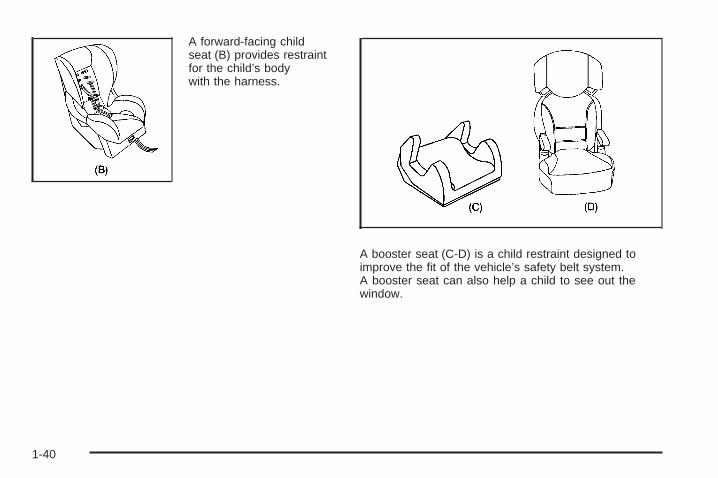
A forward-facing childseat (B) provides restraintfor the child’s bodywith the harness.
A booster seat (C-D) is a child restraint designed toimprove the fit of the vehicle’s safety belt system.A booster seat can also help a child to see out thewindow.
1-40
Securing an Add-On Child Restraint inthe Vehicle
{CAUTION:
A child can be seriously injured or killed in a crashif the child restraint is not properly secured in thevehicle. Secure the child restraint properly in thevehicle using the vehicle’s safety belt or LATCHsystem, following the instructions that came withthat child restraint and the instructions in thismanual.
To help reduce the chance of injury, the child restraintmust be secured in the vehicle. Child restraint systemsmust be secured in vehicle seats by lap belts or thelap belt portion of a lap-shoulder belt, or by the LATCHsystem. See Lower Anchors and Tethers for Children(LATCH) on page 1-43 for more information. A child canbe endangered in a crash if the child restraint is notproperly secured in the vehicle.
When securing an add-on child restraint, refer to theinstructions that come with the restraint which may be onthe restraint itself or in a booklet, or both, and to thismanual. The child restraint instructions are important,so if they are not available, obtain a replacementcopy from the manufacturer.
Keep in mind that an unsecured child restraint canmove around in a collision or sudden stop and injurepeople in the vehicle. Be sure to properly secureany child restraint in the vehicle — even when nochild is in it.
Securing the Child Within the ChildRestraint
{CAUTION:
A child can be seriously injured or killed in a crashif the child is not properly secured in the childrestraint. Secure the child properly following theinstructions that came with that child restraint.
1-41
Where to Put the RestraintAccording to accident statistics, children and infants aresafer when properly restrained in a child restraintsystem or infant restraint system secured in a rearseating position.
We recommend that children and child restraints besecured in a rear seat, including: an infant or achild riding in a rear-facing child restraint; a child ridingin a forward-facing child seat; an older child riding ina booster seat; and children, who are large enough,using safety belts.
A label on the sun visor says, “Never put a rear-facingchild restraint in the front.” This is because the riskto the rear-facing child is so great, if the airbag deploys.
{CAUTION:
A child in a rear-facing child restraint can beseriously injured or killed if the right frontpassenger airbag inflates. This is because theback of the rear-facing child restraint would bevery close to the inflating airbag. A child in a
CAUTION: (Continued)
CAUTION: (Continued)
forward-facing child restraint can be seriouslyinjured or killed if the right front passenger airbaginflates and the passenger seat is in a forwardposition.
Even if the passenger sensing system has turnedoff the right front passenger frontal airbag, nosystem is fail-safe. No one can guarantee that anairbag will not deploy under some unusualcircumstance, even though it is turned off.
Secure rear-facing child restraints in a rearseat, even if the airbag is off. If you secure aforward-facing child restraint in the right front seat,always move the front passenger seat as far backas it will go. It is better to secure the child restraintin a rear seat.
See Passenger Sensing System on page 1-63 foradditional information.
1-42
When securing a child restraint in a rear seating position,study the instructions that came with the child restraint tomake sure it is compatible with this vehicle.
Wherever a child restraint is installed, be sure to securethe child restraint properly.
Keep in mind that an unsecured child restraint canmove around in a collision or sudden stop and injurepeople in the vehicle. Be sure to properly secureany child restraint in the vehicle — even when nochild is in it.
Lower Anchors and Tethers forChildren (LATCH)The LATCH system holds a child restraint during drivingor in a crash. This system is designed to make installationof a child restraint easier. The LATCH system usesanchors in the vehicle and attachments on the childrestraint that are made for use with the LATCH system.
Make sure that a LATCH-compatible child restraint isproperly installed using the anchors, or use the vehicle’ssafety belts to secure the restraint, following theinstructions that came with that restraint, and also theinstructions in this manual. When installing a childrestraint with a top tether, you must also use either thelower anchors or the safety belts to properly securethe child restraint. A child restraint must never beinstalled using only the top tether and anchor.
In order to use the LATCH system in your vehicle, youneed a child restraint that has LATCH attachments.The child restraint manufacturer will provide youwith instructions on how to use the child restraint and itsattachments. The following explains how to attach achild restraint with these attachments in your vehicle.
Not all vehicle seating positions or child restraints havelower anchors and attachments or top tether anchorsand attachments.
1-43
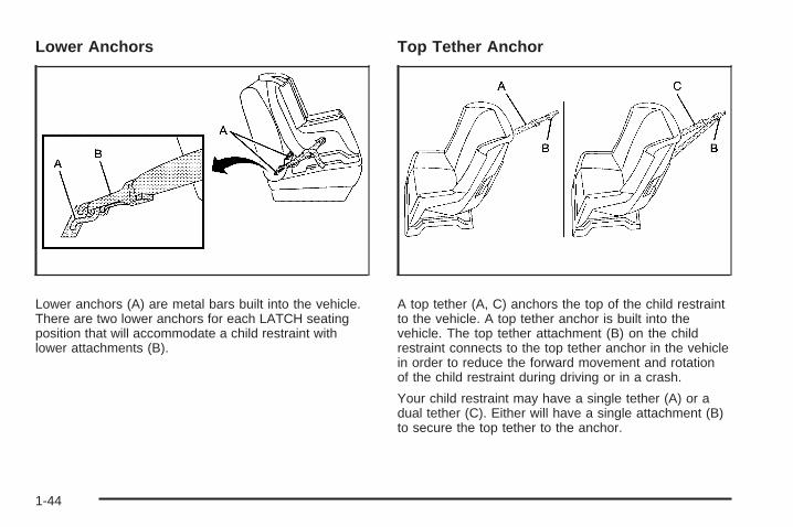
Lower Anchors
Lower anchors (A) are metal bars built into the vehicle.There are two lower anchors for each LATCH seatingposition that will accommodate a child restraint withlower attachments (B).
Top Tether Anchor
A top tether (A, C) anchors the top of the child restraintto the vehicle. A top tether anchor is built into thevehicle. The top tether attachment (B) on the childrestraint connects to the top tether anchor in the vehiclein order to reduce the forward movement and rotationof the child restraint during driving or in a crash.
Your child restraint may have a single tether (A) or adual tether (C). Either will have a single attachment (B)to secure the top tether to the anchor.
1-44

Some child restraints that have a top tether are designedfor use with or without the top tether being attached.Others require the top tether always to be attached.In Canada, the law requires that forward-facingchild restraints have a top tether, and that the tether beattached. Be sure to read and follow the instructionsfor your child restraint.
If the child restraint does not have a top tether, one canbe obtained, in kit form, for many child restraints. Askthe child restraint manufacturer whether or not a kitis available.
Lower Anchor and Top Tether AnchorLocations
i (Top Tether Anchor):Seating positions with toptether anchors.
j (Lower Anchor): Seatingpositions with two loweranchors.
To assist you in locatingthe lower anchors, eachseating position with loweranchors has two labels,near the crease betweenthe seatback and theseat cushion.
The labels are located above a flap, at the base of theseatback, in the rear outside seating positions. Theanchors are located under the flap. In order to get to theanchors you will need to pull the strap at the center ofthe seat where the seat cushion meets the seatback.This will allow you to fold the seat cushion up and out ofthe way. Lift the flap to expose the anchors and thenlower the seat cushion. Be sure the cushion islocked into place.
Second Row
1-45
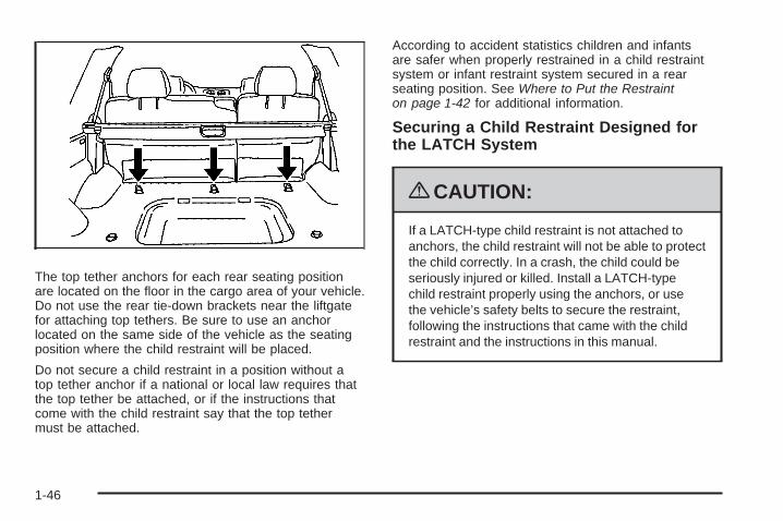
The top tether anchors for each rear seating positionare located on the floor in the cargo area of your vehicle.Do not use the rear tie-down brackets near the liftgatefor attaching top tethers. Be sure to use an anchorlocated on the same side of the vehicle as the seatingposition where the child restraint will be placed.
Do not secure a child restraint in a position without atop tether anchor if a national or local law requires thatthe top tether be attached, or if the instructions thatcome with the child restraint say that the top tethermust be attached.
According to accident statistics children and infantsare safer when properly restrained in a child restraintsystem or infant restraint system secured in a rearseating position. See Where to Put the Restrainton page 1-42 for additional information.
Securing a Child Restraint Designed forthe LATCH System
{CAUTION:
If a LATCH-type child restraint is not attached toanchors, the child restraint will not be able to protectthe child correctly. In a crash, the child could beseriously injured or killed. Install a LATCH-typechild restraint properly using the anchors, or usethe vehicle’s safety belts to secure the restraint,following the instructions that came with the childrestraint and the instructions in this manual.
1-46
{CAUTION:
Do not attach more than one child restraint to asingle anchor. Attaching more than one childrestraint to a single anchor could cause the anchoror attachment to come loose or even break duringa crash. A child or others could be injured. Toreduce the risk of serious or fatal injuries during acrash, attach only one child restraint per anchor.
{CAUTION:
Children can be seriously injured or strangled if ashoulder belt is wrapped around their neck andthe safety belt continues to tighten. Buckle anyunused safety belts behind the child restraint sochildren cannot reach them. Pull the shoulder beltall the way out of the retractor to set the lock, ifyour vehicle has one, after the child restraint hasbeen installed.
Notice: Do not let the LATCH attachments rubagainst the vehicle’s safety belts. This may damagethese parts. If necessary, move buckled safetybelts to avoid rubbing the LATCH attachments.
Do not fold the empty rear seat with a safety beltbuckled. This could damage the safety belt orthe seat. Unbuckle and return the safety belt toits stowed position, before folding the seat.
1. Attach and tighten the lower attachments to thelower anchors. If the child restraint does not havelower attachments or the desired seating positiondoes not have lower anchors, secure the childrestraint with the top tether and the safety belts.Refer to your child restraint manufacturerinstructions and the instructions in this manual.
1.1. Find the lower anchors for the desiredseating position.
1.2. Pull the strap at the center of the seat wherethe seat cushion meets the seatback. Thiswill allow you to fold the seat cushion up andout of the way. Lift the flap to expose theanchors and then lower the seat cushion.See Rear Seat Operation on page 1-11for additional information. Be sure thecushion is locked into place.
1.3. Put the child restraint on the seat.1.4. Attach and tighten the lower attachments on
the child restraint to the lower anchors.
1-47
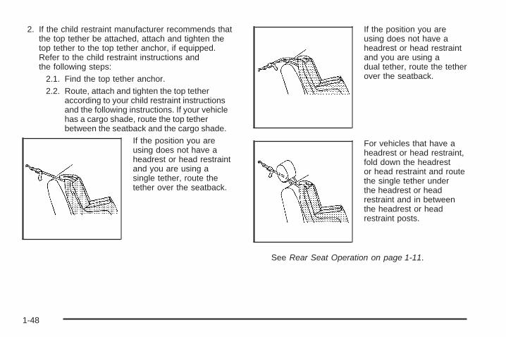
2. If the child restraint manufacturer recommends thatthe top tether be attached, attach and tighten thetop tether to the top tether anchor, if equipped.Refer to the child restraint instructions andthe following steps:
2.1. Find the top tether anchor.2.2. Route, attach and tighten the top tether
according to your child restraint instructionsand the following instructions. If your vehiclehas a cargo shade, route the top tetherbetween the seatback and the cargo shade.
If the position you areusing does not have aheadrest or head restraintand you are using asingle tether, route thetether over the seatback.
If the position you areusing does not have aheadrest or head restraintand you are using adual tether, route the tetherover the seatback.
For vehicles that have aheadrest or head restraint,fold down the headrestor head restraint and routethe single tether underthe headrest or headrestraint and in betweenthe headrest or headrestraint posts.
See Rear Seat Operation on page 1-11.
1-48
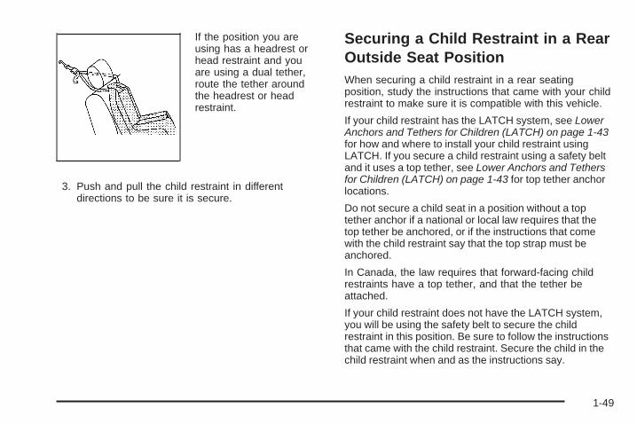
If the position you areusing has a headrest orhead restraint and youare using a dual tether,route the tether aroundthe headrest or headrestraint.
3. Push and pull the child restraint in differentdirections to be sure it is secure.
Securing a Child Restraint in a RearOutside Seat PositionWhen securing a child restraint in a rear seatingposition, study the instructions that came with your childrestraint to make sure it is compatible with this vehicle.
If your child restraint has the LATCH system, see LowerAnchors and Tethers for Children (LATCH) on page 1-43for how and where to install your child restraint usingLATCH. If you secure a child restraint using a safety beltand it uses a top tether, see Lower Anchors and Tethersfor Children (LATCH) on page 1-43 for top tether anchorlocations.
Do not secure a child seat in a position without a toptether anchor if a national or local law requires that thetop tether be anchored, or if the instructions that comewith the child restraint say that the top strap must beanchored.
In Canada, the law requires that forward-facing childrestraints have a top tether, and that the tether beattached.
If your child restraint does not have the LATCH system,you will be using the safety belt to secure the childrestraint in this position. Be sure to follow the instructionsthat came with the child restraint. Secure the child in thechild restraint when and as the instructions say.
1-49
If more than one child restraint needs to be installed inthe rear seat, be sure to read Where to Put theRestraint on page 1-42.
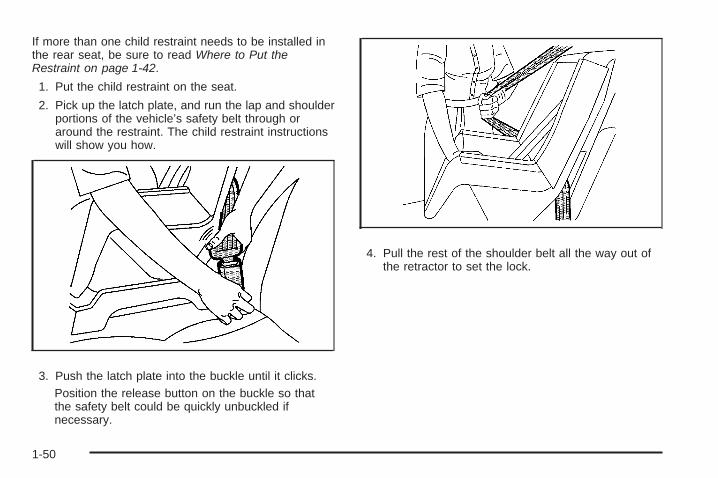
1. Put the child restraint on the seat.
2. Pick up the latch plate, and run the lap and shoulderportions of the vehicle’s safety belt through oraround the restraint. The child restraint instructionswill show you how.
3. Push the latch plate into the buckle until it clicks.Position the release button on the buckle so thatthe safety belt could be quickly unbuckled ifnecessary.
4. Pull the rest of the shoulder belt all the way out ofthe retractor to set the lock.
1-50

5. To tighten the belt, push down on the child restraint,pull the shoulder portion of the belt to tighten thelap portion of the belt, and feed the shoulderbelt back into the retractor. When installing aforward-facing child restraint, it may be helpful touse your knee to push down on the child restraintas you tighten the belt.
6. If the child restraint has a top tether, follow the childrestraint manufacturer’s instructions regarding theuse of the top tether. See Lower Anchors andTethers for Children (LATCH) on page 1-43 formore information.
7. Push and pull the child restraint in differentdirections to be sure it is secure.
To remove the child restraint, unbuckle the vehicle safetybelt and let it return to the stowed position. If the toptether is attached to a top tether anchor, disconnect it.
Securing a Child Restraint in theCenter Rear Seat PositionMany child restraints are too wide to be correctlysecured in the center rear seat, although some of themwill fit there. If the center seat position is too narrowfor your child restraint, secure it in a rear outside seatposition.
If you secure a child restraint in the center seat position,follow the instructions in Securing a Child Restraint ina Rear Outside Seat Position on page 1-49.
1-51

Securing a Child Restraint in theRight Front Seat PositionThis vehicle has airbags. A rear seat is a safer place tosecure a forward-facing child restraint. See Where toPut the Restraint on page 1-42.
In addition, the vehicle has a passenger sensing systemwhich is designed to turn off the right front passengerfrontal airbag under certain conditions. See PassengerSensing System on page 1-63 and Passenger AirbagStatus Indicator on page 3-33 for more information,including important safety information.
A label on the sun visor says, “Never put a rear-facingchild seat in the front.” This is because the risk tothe rear-facing child is so great, if the airbag deploys.
{CAUTION:
A child in a rear-facing child restraint can beseriously injured or killed if the right frontpassenger airbag inflates. This is because theback of the rear-facing child restraint would bevery close to the inflating airbag. A child in a
CAUTION: (Continued)
CAUTION: (Continued)
forward-facing child restraint can be seriouslyinjured or killed if the right front passenger airbaginflates and the passenger seat is in a forwardposition.
Even if the passenger sensing system has turnedoff the right front passenger frontal airbag, nosystem is fail-safe. No one can guarantee that anairbag will not deploy under some unusualcircumstance, even though it is turned off.
Secure rear-facing child restraints in a rearseat, even if the airbag is off. If you secure aforward-facing child restraint in the right front seat,always move the front passenger seat as far backas it will go. It is better to secure the child restraintin a rear seat.
See Passenger Sensing System on page 1-63 foradditional information.
1-52
If the child restraint has the LATCH system, see LowerAnchors and Tethers for Children (LATCH) on page 1-43for how and where to install the child restraint usingLATCH. If a child restraint is secured using a safety beltand it uses a top tether, see Lower Anchors and Tethersfor Children (LATCH) on page 1-43 for top tether anchorlocations.
Do not secure a child seat in a position without a toptether anchor if a national or local law requires that thetop tether be anchored, or if the instructions that comewith the child restraint say that the top strap must beanchored.
In Canada, the law requires that forward-facing childrestraints have a top tether, and that the tether beattached.
You will be using the lap-shoulder belt to secure thechild restraint in this position. Follow the instructions thatcame with the child restraint.
1. Move the seat as far back as it will go beforesecuring the forward-facing child restraint.When the passenger sensing system has turned offthe right front passenger frontal airbag, the offindicator on the passenger airbag status indicatorshould light and stay lit when the vehicle is started.See Passenger Airbag Status Indicator onpage 3-33.
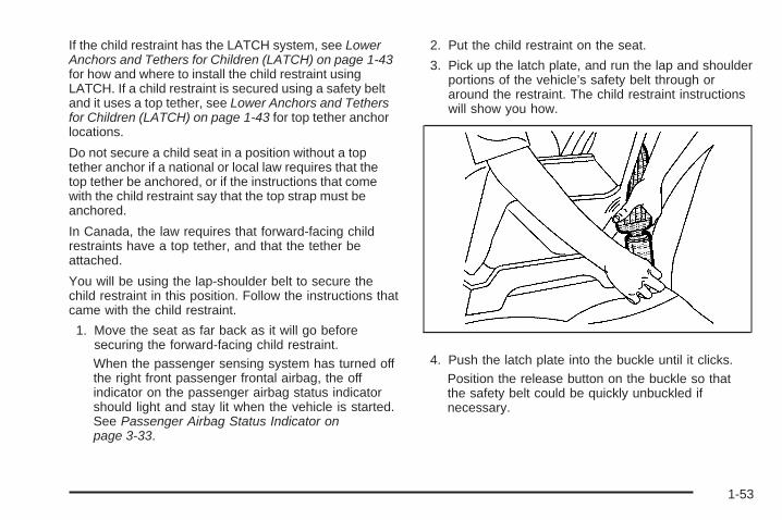
2. Put the child restraint on the seat.
3. Pick up the latch plate, and run the lap and shoulderportions of the vehicle’s safety belt through oraround the restraint. The child restraint instructionswill show you how.
4. Push the latch plate into the buckle until it clicks.Position the release button on the buckle so thatthe safety belt could be quickly unbuckled ifnecessary.
1-53

5. Pull the rest of the shoulder belt all the way out ofthe retractor to set the lock.
6. To tighten the belt, push down on the child restraint,pull the shoulder portion of the belt to tighten thelap portion of the belt and feed the shoulderbelt back into the retractor. When installing aforward-facing child restraint, it may be helpful touse your knee to push down on the child restraintas you tighten the belt.
7. Push and pull the child restraint in differentdirections to be sure it is secure.
1-54
If the airbag is off, the off indicator in the passengerairbag status indicator will come on and stay on whenthe vehicle is started.
If a child restraint has been installed and the onindicator is lit, see “If the On Indicator is Lit for aChild Restraint ” under Passenger Sensing Systemon page 1-63 for more information.
To remove the child restraint, unbuckle the vehiclesafety belt and let it return to the stowed position.
Airbag SystemThe vehicle has the following airbags:
• A frontal airbag for the driver.
• A frontal airbag for the right front passenger.
• A roof-rail airbag for the driver and the passengerseated directly behind the driver.
• A roof-rail airbag for the right front passenger andthe passenger seated directly behind the rightfront passenger.
All of the airbags in your vehicle will have the wordAIRBAG embossed in the trim or on an attached labelnear the deployment opening.
For frontal airbags, the word AIRBAG will appear on themiddle part of the steering wheel for the driver andon the instrument panel for the right front passenger.
With roof-rail airbags, the word AIRBAG will appearalong the headliner or trim.
Airbags are designed to supplement the protectionprovided by safety belts. Even though today’s airbagsare also designed to help reduce the risk of injuryfrom the force of an inflating bag, all airbags mustinflate very quickly to do their job.
1-55
Here are the most important things to know about theairbag system:
{CAUTION:
You can be severely injured or killed in a crash ifyou are not wearing your safety belt — even if youhave airbags. Airbags are designed to work withsafety belts, but do not replace them. Also, airbagsare not designed to deploy in every crash. In somecrashes safety belts are your only restraint. SeeWhen Should an Airbag Inflate? on page 1-60.
Wearing your safety belt during a crash helpsreduce your chance of hitting things inside thevehicle or being ejected from it. Airbags are“supplemental restraints” to the safety belts.Everyone in your vehicle should wear a safety beltproperly — whether or not there is an airbag for thatperson.
{CAUTION:
Airbags inflate with great force, faster than the blinkof an eye. Anyone who is up against, or very closeto, any airbag when it inflates can be seriouslyinjured or killed. Do not sit unnecessarily close tothe airbag, as you would be if you were sitting onthe edge of your seat or leaning forward. Safetybelts help keep you in position before and during acrash. Always wear your safety belt, even withairbags. The driver should sit as far back aspossible while still maintaining control of thevehicle.
Occupants should not lean on or sleep against thedoor or side windows in seating positions withroof-rail airbags.
1-56
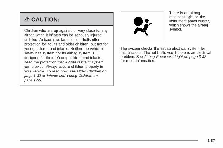
{CAUTION:
Children who are up against, or very close to, anyairbag when it inflates can be seriously injuredor killed. Airbags plus lap-shoulder belts offerprotection for adults and older children, but not foryoung children and infants. Neither the vehicle’ssafety belt system nor its airbag system isdesigned for them. Young children and infantsneed the protection that a child restraint systemcan provide. Always secure children properly inyour vehicle. To read how, see Older Children onpage 1-32 or Infants and Young Children onpage 1-35.
There is an airbagreadiness light on theinstrument panel cluster,which shows the airbagsymbol.
The system checks the airbag electrical system formalfunctions. The light tells you if there is an electricalproblem. See Airbag Readiness Light on page 3-32for more information.
1-57
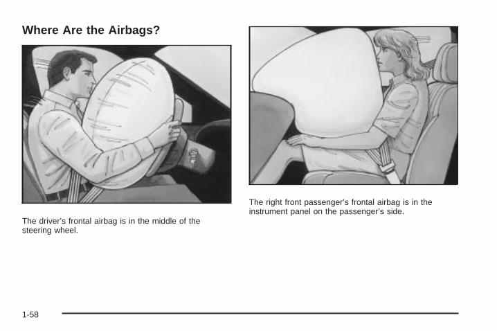
Where Are the Airbags?
The driver’s frontal airbag is in the middle of thesteering wheel.
The right front passenger’s frontal airbag is in theinstrument panel on the passenger’s side.
1-58
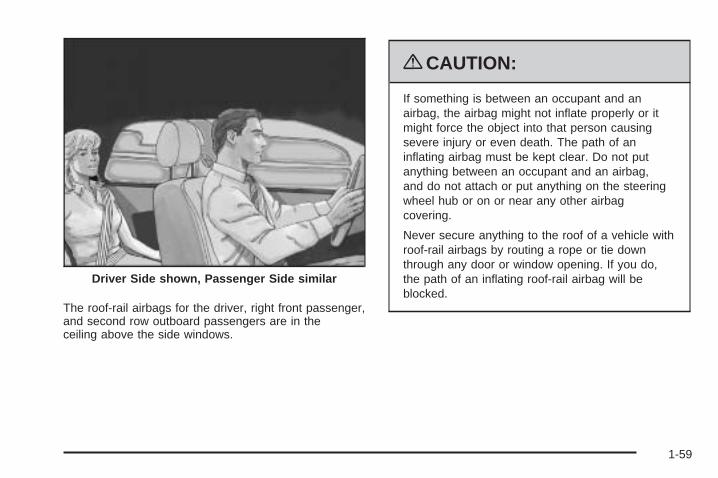
The roof-rail airbags for the driver, right front passenger,and second row outboard passengers are in theceiling above the side windows.
{CAUTION:
If something is between an occupant and anairbag, the airbag might not inflate properly or itmight force the object into that person causingsevere injury or even death. The path of aninflating airbag must be kept clear. Do not putanything between an occupant and an airbag,and do not attach or put anything on the steeringwheel hub or on or near any other airbagcovering.
Never secure anything to the roof of a vehicle withroof-rail airbags by routing a rope or tie downthrough any door or window opening. If you do,the path of an inflating roof-rail airbag will beblocked.
Driver Side shown, Passenger Side similar
1-59
When Should an Airbag Inflate?Frontal airbags are designed to inflate in moderate tosevere frontal or near-frontal crashes to help reduce thepotential for severe injuries mainly to the driver’s orright front passenger’s head and chest. However, theyare only designed to inflate if the impact exceeds apredetermined deployment threshold. Deploymentthresholds are used to predict how severe a crash islikely to be in time for the airbags to inflate andhelp restrain the occupants.
Whether your frontal airbags will or should deploy is notbased on how fast your vehicle is traveling. It dependslargely on what you hit, the direction of the impact,and how quickly your vehicle slows down.
Frontal airbags may inflate at different crash speeds.For example:
• If the vehicle hits a stationary object, the airbagscould inflate at a different crash speed than if thevehicle hits a moving object.
• If the vehicle hits an object that deforms, theairbags could inflate at a different crash speed thanif the vehicle hits an object that does not deform.
• If the vehicle hits a narrow object (like a pole), theairbags could inflate at a different crash speedthan if the vehicle hits a wide object (like a wall).
• If the vehicle goes into an object at an angle, theairbags could inflate at a different crash speedthan if the vehicle goes straight into the object.
Thresholds can also vary with specific vehicle design.
Frontal airbags are not intended to inflate during vehiclerollovers, rear impacts, or in many side impacts.
In addition, your vehicle has dual-stage frontal airbags.Dual-stage airbags adjust the restraint according tocrash severity. Your vehicle has electronic frontalsensors, which help the sensing system distinguishbetween a moderate frontal impact and a more severefrontal impact. For moderate frontal impacts, dual-stageairbags inflate at a level less than full deployment.For more severe frontal impacts, full deployment occurs.
Your vehicle has seat position sensors which enablesthe sensing system to monitor the position of the driver’sand right front passenger’s seat. The sensors provideinformation that is used to determine if the airbagsshould deploy at a reduced level or at full deployment.
Your vehicle has roof-rail airbags. See Airbag Systemon page 1-55. Roof-rail airbags are intended to inflate inmoderate to severe side crashes. In addition, theseroof-rail airbags are intended to inflate during a rollover.Roof-rail airbags will inflate if the crash severity isabove the system’s designed threshold level. Thethreshold level can vary with specific vehicle design.
1-60

Roof-rail airbags are not intended to inflate in frontalimpacts, near-frontal impacts, or rear impacts. Bothroof-rail airbags will deploy when either side of the vehicleis struck or if the sensing system predicts that the vehicleis about to roll over.
In any particular crash, no one can say whether anairbag should have inflated simply because of thedamage to a vehicle or because of what the repair costswere. For frontal airbags, inflation is determined by whatthe vehicle hits, the angle of the impact, and how quicklythe vehicle slows down. For roof-rail airbags, deploymentis determined by the location and severity of the sideimpact. In a rollover event, roof-rail airbag deploymentis determined by the direction of the roll.
What Makes an Airbag Inflate?In a deployment event, the sensing system sends anelectrical signal triggering a release of gas from theinflator. Gas from the inflator fills the airbag causing thebag to break out of the cover and deploy. The inflator, theairbag, and related hardware are all part of the airbagmodule.
Frontal airbag modules are located inside the steeringwheel and instrument panel. For vehicles with roof-railairbags, there are airbag modules in the ceiling of thevehicle, near the side windows that have occupantseating positions.
How Does an Airbag Restrain?In moderate to severe frontal or near frontal collisions,even belted occupants can contact the steering wheelor the instrument panel. In moderate to severe sidecollisions, even belted occupants can contact the insideof the vehicle.
Airbags supplement the protection provided by safetybelts. Frontal airbags distribute the force of the impactmore evenly over the occupant’s upper body, stoppingthe occupant more gradually. Roof-rail airbags distributethe force of the impact more evenly over the occupant’supper body.
Rollover capable roof-rail airbags are designed to helpcontain the head and chest of occupants in the outboardseating positions in the first and second rows. Therollover capable roof-rail airbags are designed to helpreduce the risk of full or partial ejection in rollover events,although no system can prevent all such ejections.
But airbags would not help in many types of collisions,primarily because the occupant’s motion is not towardthose airbags. See When Should an Airbag Inflate? onpage 1-60 for more information.
Airbags should never be regarded as anything morethan a supplement to safety belts.
1-61

What Will You See After an AirbagInflates?After the frontal airbags inflate, they quickly deflate, soquickly that some people may not even realize an airbaginflated. Roof-rail airbags may still be at least partiallyinflated for some time after they deploy. Somecomponents of the airbag module may be hot for severalminutes. For location of the airbag modules, see WhatMakes an Airbag Inflate? on page 1-61.
The parts of the airbag that come into contact with youmay be warm, but not too hot to touch. There maybe some smoke and dust coming from the vents in thedeflated airbags. Airbag inflation does not preventthe driver from seeing out of the windshield or beingable to steer the vehicle, nor does it prevent peoplefrom leaving the vehicle.
{CAUTION:
When an airbag inflates, there may be dust in theair. This dust could cause breathing problems forpeople with a history of asthma or other breathingtrouble. To avoid this, everyone in the vehicleshould get out as soon as it is safe to do so. If youhave breathing problems but cannot get out of thevehicle after an airbag inflates, then get fresh air byopening a window or a door. If you experiencebreathing problems following an airbag deployment,you should seek medical attention.
The vehicle has a feature that may automatically unlockthe doors, turn the interior lamps on, and turn thehazard warning flashers on when the airbags inflate.You can lock the doors, turn the interior lamps off, andturn the hazard warning flashers off by using thecontrols for those features.
1-62

In many crashes severe enough to inflate the airbag,windshields are broken by vehicle deformation.Additional windshield breakage may also occurfrom the right front passenger airbag.
• Airbags are designed to inflate only once. After anairbag inflates, you will need some new parts forthe airbag system. If you do not get them, the airbagsystem will not be there to help protect you inanother crash. A new system will include airbagmodules and possibly other parts. The servicemanual for the vehicle covers the need to replaceother parts.
• The vehicle has a crash sensing and diagnosticmodule which records information after a crash.See Vehicle Data Recording and Privacy onpage 7-17 and Event Data Recorders on page 7-18.
• Let only qualified technicians work on the airbagsystems. Improper service can mean that anairbag system will not work properly. See yourdealer/retailer for service.
Passenger Sensing SystemThe vehicle has a passenger sensing system for the rightfront passenger position. The passenger airbag statusindicator will be visible in the rearview mirror when thevehicle is started.
The words ON and OFF, or the symbol for on and off,will be visible during the system check. When the systemcheck is complete, either the word ON or OFF, or thesymbol for on or off, will be visible. See Passenger AirbagStatus Indicator on page 3-33.
United States
Canada
1-63

The passenger sensing system will turn off the rightfront passenger frontal airbag under certain conditions.The driver airbags and roof-rail airbags are notaffected by the passenger sensing system.
The passenger sensing system works with sensors thatare part of the right front passenger seat. The sensorsare designed to detect the presence of a properly-seatedoccupant and determine if the right front passengerfrontal airbag should be enabled (may inflate) or not.
According to accident statistics, children are safer whenproperly secured in a rear seat in the correct childrestraint for their weight and size.
We recommend that children be secured in a rear seat,including: an infant or a child riding in a rear-facingchild restraint; a child riding in a forward-facing childseat; an older child riding in a booster seat; and children,who are large enough, using safety belts.
A label on the sun visor says, “Never put a rear-facingchild seat in the front.” This is because the risk tothe rear-facing child is so great, if the airbag deploys.
{CAUTION:
A child in a rear-facing child restraint can beseriously injured or killed if the right frontpassenger airbag inflates. This is because theback of the rear-facing child restraint would bevery close to the inflating airbag. A child in aforward-facing child restraint can be seriouslyinjured or killed if the right front passenger airbaginflates and the passenger seat is in a forwardposition.
Even if the passenger sensing system has turnedoff the right front passenger frontal airbag, nosystem is fail-safe. No one can guarantee thatan airbag will not deploy under some unusualcircumstance, even though the airbag is turned off.
Secure rear-facing child restraints in a rear seat,even if the airbag is off. If you secure aforward-facing child restraint in the right front seat,always move the front passenger seat as far backas it will go. It is better to secure the child restraintin a rear seat.
1-64

The passenger sensing system is designed to turn offthe right front passenger frontal airbag if:
• The right front passenger seat is unoccupied.
• The system determines that an infant is present ina rear-facing infant seat.
• The system determines that a small child is presentin a child restraint.
• The system determines that a small child is presentin a booster seat.
• A right front passenger takes his/her weight off ofthe seat for a period of time.
• The right front passenger seat is occupied by asmaller person, such as a child who has outgrownchild restraints.
• Or, if there is a critical problem with the airbagsystem or the passenger sensing system.
When the passenger sensing system has turned off theright front passenger frontal airbag, the off indicatorwill light and stay lit to remind you that the airbag is off.See Passenger Airbag Status Indicator on page 3-33.
The passenger sensing system is designed to turnon (may inflate) the right front passenger frontal airbaganytime the system senses that a person of adultsize is sitting properly in the right front passenger seat.
When the passenger sensing system has allowed theairbag to be enabled, the on indicator will light and staylit to remind you that the airbag is active.
For some children who have outgrown child restraintsand for very small adults, the passenger sensing systemmay or may not turn off the right front passengerfrontal airbag, depending upon the person’s seatingposture and body build. Everyone in the vehicle whohas outgrown child restraints should wear a safety beltproperly — whether or not there is an airbag for thatperson.
{CAUTION:
If the airbag readiness light ever comes on andstays on, it means that something may be wrongwith the airbag system. To help avoid injury toyourself or others, have the vehicle serviced rightaway. See Airbag Readiness Light on page 3-32for more information, including important safetyinformation.
1-65
If the On Indicator is Lit for a ChildRestraintIf a child restraint has been installed and the on indicatoris lit:1. Turn the vehicle off.2. Remove the child restraint from the vehicle.3. Remove any additional items from the seat such as
blankets, cushions, seat covers, seat heaters, or seatmassagers.
4. Reinstall the child restraint following the directionsprovided by the child restraint manufacturer andrefer to Securing a Child Restraint in the Right FrontSeat Position on page 1-52.
5. If, after reinstalling the child restraint and restartingthe vehicle, the on indicator is still lit, turn the vehicleoff. Then slightly recline the vehicle seatback andadjust the seat cushion, if adjustable, to make surethat the vehicle seatback is not pushing the childrestraint into the seat cushion.Also make sure the child restraint is not trappedunder the vehicle head restraint. If this happens,adjust the head restraint. See Head Restraintson page 1-10.
6. Restart the vehicle.If the on indicator is still lit, secure the child in thechild restraint in a rear seat position in the vehicle,and check with your dealer/retailer.
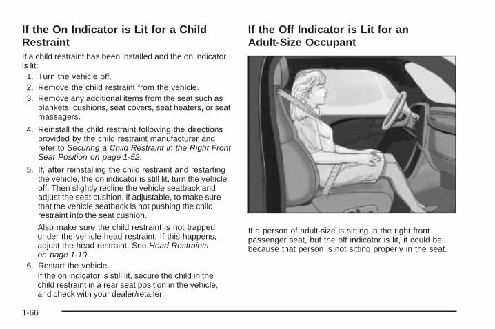
If the Off Indicator is Lit for anAdult-Size Occupant
If a person of adult-size is sitting in the right frontpassenger seat, but the off indicator is lit, it could bebecause that person is not sitting properly in the seat.
1-66

If this happens, use the following steps to allow thesystem to detect that person and enable the right frontpassenger frontal airbag:
1. Turn the vehicle off.
2. Remove any additional material from the seat, suchas blankets, cushions, seat covers, seat heaters, orseat massagers.
3. Place the seatback in the fully upright position.
4. Have the person sit upright in the seat, centered onthe seat cushion, with legs comfortably extended.
5. Restart the vehicle and have the person remain inthis position for two to three minutes after the onindicator is lit.
Additional Factors Affecting SystemOperationSafety belts help keep the passenger in position on theseat during vehicle maneuvers and braking, whichhelps the passenger sensing system maintain thepassenger airbag status. See “Safety Belts” and “ChildRestraints” in the Index for additional informationabout the importance of proper restraint use.
A thick layer of additional material, such as a blanket orcushion, or aftermarket equipment such as seat covers,seat heaters, and seat massagers can affect how well thepassenger sensing system operates. We recommendthat you not use seat covers or other aftermarketequipment except when approved by GM for your specificvehicle. See Adding Equipment to Your Airbag-EquippedVehicle on page 1-68 for more information aboutmodifications that can affect how the system operates.
{CAUTION:
Stowing of articles under the passenger seat orbetween the passenger seat cushion and seatbackmay interfere with the proper operation of thepassenger sensing system.
1-67

Servicing Your Airbag-EquippedVehicleAirbags affect how the vehicle should be serviced.There are parts of the airbag system in several placesaround the vehicle. Your dealer/retailer and theservice manual have information about servicing thevehicle and the airbag system. To purchase a servicemanual, see Service Publications Ordering Informationon page 7-16.
{CAUTION:
For up to 10 seconds after the ignition is turned offand the battery is disconnected, an airbag can stillinflate during improper service. You can be injuredif you are close to an airbag when it inflates. Avoidyellow connectors. They are probably part of theairbag system. Be sure to follow proper serviceprocedures, and make sure the person performingwork for you is qualified to do so.
Adding Equipment to YourAirbag-Equipped Vehicle
Q: Is there anything I might add to or changeabout the vehicle that could keep the airbagsfrom working properly?
A: Yes. If you add things that change your vehicle’sframe, bumper system, height, front end or sidesheet metal, they may keep the airbag system fromworking properly. Changing or moving any parts ofthe front seats, safety belts, the airbag sensing anddiagnostic module, steering wheel, instrument panel,roof-rail airbag modules, ceiling headliner or pillargarnish trim, rearview mirror, front sensors, rolloversensor module, or airbag wiring can affect theoperation of the airbag system.
In addition, your vehicle has a passenger sensingsystem for the right front passenger’s position, whichincludes sensors that are part of the passenger’sseat. The passenger sensing system may notoperate properly if the original seat trim is replacedwith non-GM covers, upholstery or trim, or with GMcovers, upholstery or trim designed for a differentvehicle.
1-68
Any object, such as an aftermarket seat heater or acomfort enhancing pad or device, installed under oron top of the seat fabric, could also interfere with theoperation of the passenger sensing system. Thiscould either prevent proper deployment of thepassenger airbag(s) or prevent the passengersensing system from properly turning off thepassenger airbag(s). See Passenger SensingSystem on page 1-63.
If you have any questions about this, you shouldcontact Customer Assistance before you modifyyour vehicle. The phone numbers and addressesfor Customer Assistance are in Step Two ofthe Customer Satisfaction Procedure in this manual.See Customer Satisfaction Procedure on page 7-2.
If your vehicle has rollover roof-rail airbags, seeDifferent Size Tires and Wheels on page 5-77for additional important information.
Q: Because I have a disability, I have to get myvehicle modified. How can I find out whetherthis will affect my airbag system?
A: If you have questions, call Customer Assistance.The phone numbers and addresses for CustomerAssistance are in Step Two of the CustomerSatisfaction Procedure in this manual. SeeCustomer Satisfaction Procedure on page 7-2.
In addition, your dealer/retailer and the service manualhave information about the location of the airbagsensors, sensing and diagnostic module and airbagwiring.
1-69
Restraint System Check
Checking the Restraint Systems
Safety BeltsNow and then, check the safety belt reminder light,safety belts, buckles, latch plates, retractors, andanchorages are all working properly.
Look for any other loose or damaged safety belt systemparts that might keep a safety belt system from doingits job. See your dealer/retailer to have it repaired. Tornor frayed safety belts may not protect you in a crash.They can rip apart under impact forces. If a belt is tornor frayed, get a new one right away.
Make sure the safety belt reminder light is working.See Safety Belt Reminders on page 3-31 for moreinformation.
Keep safety belts clean and dry. See Care of SafetyBelts on page 5-112.
AirbagsThe airbag system does not need regularly scheduledmaintenance or replacement. Make sure the airbagreadiness light is working. See Airbag Readiness Lighton page 3-32 for more information.
Notice: If an airbag covering is damaged, opened,or broken, the airbag may not work properly.Do not open or break the airbag coverings. If thereare any opened or broken airbag covers, havethe airbag covering and/or airbag module replaced.For the location of the airbag modules, see WhatMakes an Airbag Inflate? on page 1-61. Seeyour dealer/retailer for service.
1-70

Replacing Restraint System PartsAfter a Crash
{CAUTION:
A crash can damage the restraint systems in yourvehicle. A damaged restraint system may notproperly protect the person using it, resulting inserious injury or even death in a crash. To helpmake sure your restraint systems are workingproperly after a crash, have them inspected andany necessary replacements made as soon aspossible.
If the vehicle has been in a crash, do you need newsafety belts or LATCH system (if equipped) parts?
After a very minor crash, nothing may be necessary.But the safety belt assemblies that were used during anycrash may have been stressed or damaged. See yourdealer/retailer to have the safety belt assembliesinspected or replaced.
If the vehicle has the LATCH system and it wasbeing used during a crash, you may need new LATCHsystem parts.
New parts and repairs may be necessary even if thesafety belt or LATCH system (if equipped), wasnot being used at the time of the crash.
If an airbag inflates, you will need to replace airbagsystem parts. See the part on the airbag system earlierin this section.
Have the safety belt pretensioners checked if thevehicle has been in a crash, if the airbag readiness lightstays on after the vehicle is started, or while you aredriving. See Airbag Readiness Light on page 3-32.
1-71

✍ NOTES
1-72

Keys ...............................................................2-3Remote Keyless Entry (RKE) System ................2-4Remote Keyless Entry (RKE)
System Operation .......................................2-5Doors and Locks .............................................2-7
Door Locks ....................................................2-7Power Door Locks ..........................................2-8Delayed Locking .............................................2-8Programmable Automatic Door Locks ................2-9Rear Door Security Locks ..............................2-12Lockout Protection ........................................2-12Liftgate/Liftglass ............................................2-13
Windows ........................................................2-14Power Windows ............................................2-15Sun Visors ...................................................2-16
Theft-Deterrent Systems ..................................2-17Content Theft-Deterrent .................................2-17Passlock® (U.S. Only) ...................................2-18PASS-Key® III+ Electronic Immobilizer .............2-19PASS-Key® III+ Electronic Immobilizer
Operation (Canada Only) ............................2-19
Starting and Operating Your Vehicle ................2-21New Vehicle Break-In ....................................2-21Ignition Positions ..........................................2-22Retained Accessory Power (RAP) ...................2-23Starting the Engine .......................................2-23Adjustable Throttle and Brake Pedal ................2-24Engine Coolant Heater ..................................2-25Active Fuel Management™ .............................2-26Automatic Transmission Operation ...................2-26Four-Wheel Drive ..........................................2-30Parking Brake ..............................................2-34Shifting Into Park ..........................................2-35Shifting Out of Park ......................................2-37Parking Over Things That Burn .......................2-37Engine Exhaust ............................................2-38Running the Vehicle While Parked ..................2-39
Mirrors ...........................................................2-40Manual Rearview Mirror .................................2-40Automatic Dimming Rearview Mirror ................2-40Compass .....................................................2-42
Section 2 Features and Controls
2-1
Outside Manual Mirrors ..................................2-43Outside Power Mirrors ...................................2-44Outside Convex Mirror ...................................2-44Outside Heated Mirrors ..................................2-44
OnStar® System .............................................2-45Universal Home Remote System ......................2-48
Universal Home Remote System Operation(With One Triangular LED) ...........................2-49
Storage Areas ................................................2-53Glove Box ...................................................2-53Overhead Console ........................................2-53Center Console Storage .................................2-54Luggage Carrier ...........................................2-54Rear Floor Storage Cover ..............................2-55Convenience Net ..........................................2-56Cargo Cover ................................................2-56Cargo Tie Downs ..........................................2-57
Sunroof .........................................................2-57
Section 2 Features and Controls
2-2

Keys
{CAUTION:
Leaving children in a vehicle with the ignition keyis dangerous for many reasons, children or otherscould be badly injured or even killed. They couldoperate the power windows or other controls oreven make the vehicle move. The windows willfunction with the keys in the ignition and childrencould be seriously injured or killed if caught in thepath of a closing window. Do not leave the keys ina vehicle with children.
This vehicle has keys that can be used for the ignitionand door lock that will fit with either side up.
When a new vehicle is delivered, the dealer/retailerprovides the owner with a pair of identical keys anda key code number.
2-3

The key code number tells your dealer/retailer or aqualified locksmith how to make extra keys. Keep thisnumber in a safe place. If you lose your keys, you will beable to have new ones made easily using this number.Your selling dealer/retailer should also have this number.
Notice: If you ever lock your keys in the vehicle,you may have to damage the vehicle to get in.Be sure you have spare keys.
If you ever get locked out of your vehicle, call theRoadside Assistance Center. See Roadside AssistanceProgram on page 7-7.
Remote Keyless Entry (RKE)SystemIf this vehicle has the Remote Keyless Entry (RKE)system, it operates on a radio frequency subjectto Federal Communications Commission (FCC) Rulesand with Industry Canada.
This device complies with Part 15 of the FCC Rules.Operation is subject to the following two conditions:
1. This device may not cause interference.
2. This device must accept any interference received,including interference that may cause undesiredoperation of the device.
This device complies with RSS-210 of Industry Canada.Operation is subject to the following two conditions:
1. This device may not cause interference.
2. This device must accept any interference received,including interference that may cause undesiredoperation of the device.
Changes or modifications to this system by other thanan authorized service facility could void authorization touse this equipment.
If there is a decrease in the RKE operating range,try this:
• Check the distance. The transmitter may be too farfrom the vehicle. Stand closer during rainy orsnowy weather.
• Check the location. Other vehicles or objects maybe blocking the signal. Take a few steps to theleft or right, hold the transmitter higher, andtry again.
• Check the transmitter’s battery. See “BatteryReplacement” later in this section.
• If the transmitter is still not working correctly, seeyour dealer/retailer or a qualified technician forservice.
2-4

Remote Keyless Entry (RKE)System OperationThe Remote Keyless Entry (RKE) transmitter functionswork up to 30 feet (9 m) away from the vehicle.
There are other conditions which can affect theperformance of the transmitter. See Remote KeylessEntry (RKE) System on page 2-4.
K (Unlock): Press onceto unlock the driver door.The parking lamps flash andthe interior lights come on.Press K a second timewithin three seconds tounlock all the doors.
To program different feedback settings through theDriver Information Center (DIC), see Driver InformationCenter (DIC) on page 3-47.
Q (Lock): Press to lock all the doors. Press Q againwithin three seconds and the horn chirps.
L (Panic): Press to sound the horn. The headlampsand taillamps flash for up to 30 seconds. To turn itoff, press L again, or wait 30 seconds, or startthe vehicle.
Programming Transmitters to theVehicleOnly RKE transmitters programmed to the vehiclewill work. If a transmitter is lost or stolen, a replacementcan be purchased and programmed through yourdealer/retailer. When the replacement transmitter isprogrammed to the vehicle, all remaining transmittersmust also be programmed. Any lost or stolen transmittersno longer work once the new transmitter is programmed.Each vehicle can have up to four transmittersprogrammed to it.
2-5

Battery ReplacementReplace the battery if the KEY FOB # BATTERYLOW message displays in the DIC. See “KEYFOB # BATTERY LOW” under DIC Warnings andMessages on page 3-51 for additional information.
Notice: When replacing the battery, do not touchany of the circuitry on the transmitter. Staticfrom your body could damage the transmitter.
To replace the battery:
1. Separate the transmitter with a flat, thin objectinserted into the slot between the covers of thetransmitter housing.
2. Remove the old battery. Do not use a metal object.
3. Insert the new battery. Replace with a CR2032or equivalent battery.
4. Snap the transmitter back together.
2-6
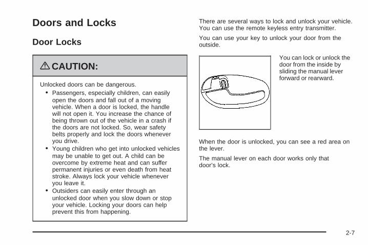
Doors and Locks
Door Locks
{CAUTION:
Unlocked doors can be dangerous.• Passengers, especially children, can easily
open the doors and fall out of a movingvehicle. When a door is locked, the handlewill not open it. You increase the chance ofbeing thrown out of the vehicle in a crash ifthe doors are not locked. So, wear safetybelts properly and lock the doors wheneveryou drive.
• Young children who get into unlocked vehiclesmay be unable to get out. A child can beovercome by extreme heat and can sufferpermanent injuries or even death from heatstroke. Always lock your vehicle wheneveryou leave it.
• Outsiders can easily enter through anunlocked door when you slow down or stopyour vehicle. Locking your doors can helpprevent this from happening.
There are several ways to lock and unlock your vehicle.You can use the remote keyless entry transmitter.
You can use your key to unlock your door from theoutside.
You can lock or unlock thedoor from the inside bysliding the manual leverforward or rearward.
When the door is unlocked, you can see a red area onthe lever.
The manual lever on each door works only thatdoor’s lock.
2-7
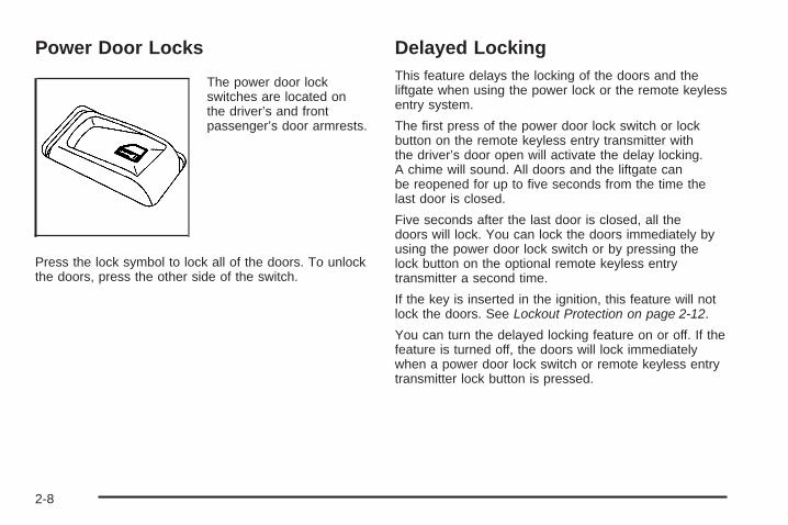
Power Door Locks
The power door lockswitches are located onthe driver’s and frontpassenger’s door armrests.
Press the lock symbol to lock all of the doors. To unlockthe doors, press the other side of the switch.
Delayed LockingThis feature delays the locking of the doors and theliftgate when using the power lock or the remote keylessentry system.
The first press of the power door lock switch or lockbutton on the remote keyless entry transmitter withthe driver’s door open will activate the delay locking.A chime will sound. All doors and the liftgate canbe reopened for up to five seconds from the time thelast door is closed.
Five seconds after the last door is closed, all thedoors will lock. You can lock the doors immediately byusing the power door lock switch or by pressing thelock button on the optional remote keyless entrytransmitter a second time.
If the key is inserted in the ignition, this feature will notlock the doors. See Lockout Protection on page 2-12.
You can turn the delayed locking feature on or off. If thefeature is turned off, the doors will lock immediatelywhen a power door lock switch or remote keyless entrytransmitter lock button is pressed.
2-8
Programming Delayed LockingTo turn the delayed locking feature on or off, do thefollowing:
1. Press and hold the power door lock switch on thedriver’s door in the lock position.
2. Press the remote keyless entry transmitter unlockbutton twice.
If the delayed locking feature was on, it will now be off.If the feature was off, it will now be on.
Programmable Automatic DoorLocksYour vehicle is equipped with an automatic lock/unlockfeature which enables you to program your vehicle’spower door locks. You can program this feature throughthe Driver Information Center (DIC), or by the followingmethod. See DIC Vehicle Customization on page 3-56.
Programmable Locking FeatureFollowing are the two locking modes that can beprogrammed:
Mode 1: All doors lock when the transmission is shiftedout of (P) Park.
Mode 2: All doors lock when the vehicle speed isgreater than 8 mph (13 km/h).
The automatic door locks were pre-programmed at thefactory to lock all the doors when the transmissionis shifted into gear. The following instructions detail howto program your door locks differently than the factorysetting. Choose one of the two programming optionslisted previously before entering the program mode.
To enter the program mode, do the following:
1. Begin with the ignition off. Then pull the turnsignal/multifunction lever toward you and holdit there while you perform the next step.
2. Turn the key to ON/RUN and LOCK/OFF twice.Then, with the key in LOCK/OFF, release theturn signal/multifunction lever. Once you do this,you will hear the lock switch lock and unlock,the horn will chirp twice, and a 30-second programtimer will begin.
2-9

3. You are now ready to program the automatic doorlocks. Select one of the two programming optionslisted previously, and press the lock side of thepower door lock switch to cycle through thelock options. You will have 30 seconds to beginprogramming. If you exceed the 30-second limit,the locks will automatically lock and unlock and thehorn will chirp twice to indicate that you have leftthe program mode. If this occurs, repeat theprocedure beginning with Step 1 to re-enter theprogramming mode.
You can exit the program mode any time by turning theignition to ON/RUN. The locks will automatically lockand unlock and the horn will chirp twice to indicate thatyou are leaving the program mode. If the lock/unlockswitches are not pressed while in the programmingmode, the current auto lock/unlock setting will not bemodified.
See your dealer for more information.
Programmable Unlocking FeatureThe following is the list of available programmingoptions:
Mode 1: Driver’s door unlocks when the transmission isshifted into (P) Park.
Mode 2: All doors unlock when the transmission isshifted into (P) Park.
Mode 3: All doors unlock when the key is removedfrom the ignition.
Mode 4: No automatic door unlock.
The automatic door locks were pre-programmed at thefactory to unlock all doors once the transmission isshifted to (P) Park. The following instructions detail howto program your door locks differently than the factorysetting. Choose one of the four programming optionslisted previously before entering the program mode.
2-10
To enter the program mode you need to do the following:1. Begin with the ignition off. Then pull the turn signal/
multifunction lever toward you and hold it there whileyou perform the next step.
2. Turn the key to ON/RUN and LOCK/OFF twice.Then, with the key in LOCK/OFF, release the turnsignal/multifunction lever. Once you do this, you willhear the lock switch lock and unlock, the horn willchirp twice, and a 30-second program timer willbegin.
3. You are now ready to program the automatic doorlocks. Select one of the four programming optionslisted above, and press the unlock side of the powerdoor lock switch to cycle through the unlockingoptions. You will have 30 seconds to begin
programming. If you exceed the 30-second limit,the locks will automatically lock and unlock and thehorn will chirp twice to indicate that you have leftthe program mode. If this occurs, repeat theprocedure beginning with Step 1 to re-enter theprogramming mode.
You can exit the program mode any time by turning theignition to ON/RUN. The locks will automatically lock andunlock and the horn will chirp twice to indicate that youare leaving the program mode. If the lock/unlock switchesare not pressed while in the programming mode, thecurrent auto lock/unlock setting will not be modified.
See your dealer for more information.
2-11

Rear Door Security LocksYour vehicle may have this feature. You can lock the reardoors so they cannot be opened from the inside bypassengers. To use one of these locks do the following:
1. Open one of the rear doors. You will find a securitylock lever located on the inside edge of eachrear door.
2. Move the lever down toengage the securitylock. Move the leverup to disengagethe security lock.
3. Close the door.
The rear doors of your vehicle cannot be opened fromthe inside while this feature is in use. If you want to openthe rear door while the security lock is on, unlock thedoor and open the door from the outside.
Lockout ProtectionThis feature stops the power door locks from lockingwhen the key is in the ignition and a door is opento protect you from locking your key in the vehicle.
If the power lock switch is pressed when a door is openand the key is in the ignition, all the doors will lockand then the driver’s door will unlock.
2-12
Liftgate/Liftglass
{CAUTION:
It can be dangerous to drive with the liftgate orliftglass open because carbon monoxide (CO) gascan come into your vehicle. You cannot see orsmell CO. It can cause unconsciousness and evendeath. If you must drive with the liftgate open or ifelectrical wiring or other cable connections mustpass through the seal between the body and theliftgate or liftglass:
• Make sure all other windows are shut.• Turn the fan on your climate control system to
its highest speed and select the control settingthat will force outside air into your vehicle.See “Climate Control System” in the Index.
• If you have air outlets on or under theinstrument panel, open them all the way.See Engine Exhaust on page 2-38.
Liftgate ReleaseTo unlock the liftgate, use the power door lock switchor the remote keyless entry transmitter. See RemoteKeyless Entry (RKE) System Operation on page 2-5.The liftglass will also unlock when the liftgate isunlocked.
Press the button on the liftglass to open it. To open theentire liftgate, lift the handle located in the center ofthe liftgate. When the liftgate is opened, the liftglasswill lock after a short delay.
Emergency Release for OpeningLiftgate1. Remove the trim plug, located on the inside of the
liftgate in the center, to expose the access hole inthe trim panel.
2. Use a tool to reach through the access hole in thetrim panel.
3. Pry the left release lever up to the unlock position.Pry the right release lever up to unlatch the liftgate.
4. Reinstall the trim plug.
2-13
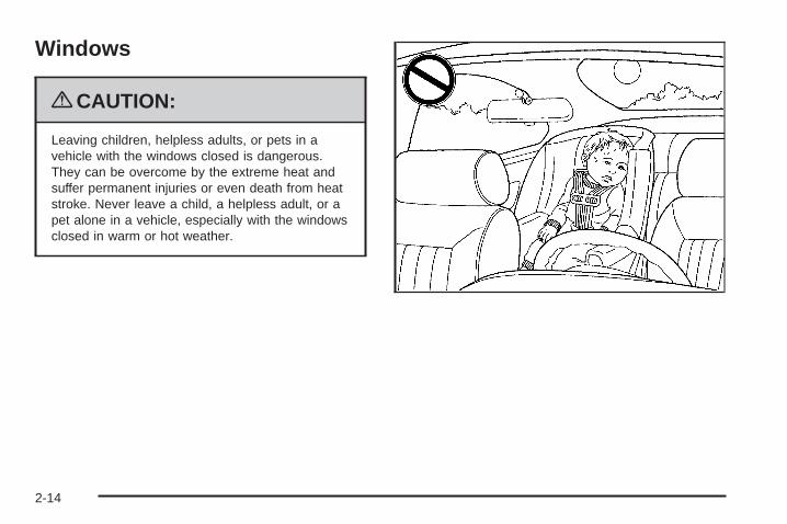
Windows
{CAUTION:
Leaving children, helpless adults, or pets in avehicle with the windows closed is dangerous.They can be overcome by the extreme heat andsuffer permanent injuries or even death from heatstroke. Never leave a child, a helpless adult, or apet alone in a vehicle, especially with the windowsclosed in warm or hot weather.
2-14

Power Windows
{CAUTION:
Leaving children in a vehicle with the keys isdangerous for many reasons, children or otherscould be badly injured or even killed. They couldoperate the power windows or other controls oreven make the vehicle move. The windows willfunction and they could be seriously injured orkilled if caught in the path of a closing window.Do not leave keys in a vehicle with children.
When there are children in the rear seat use thewindow lockout button to prevent unintentionaloperation of the windows.
The controls for the power windows are located on thearmrest on each of the side doors. With power windows,the switches operate the windows when the ignition isin ON/RUN, ACC/ACCESSORY or when RetainedAccessory Power (RAP) is active. See RetainedAccessory Power (RAP) on page 2-23. The driver’s dooralso has a switch for each of the passenger’s windows.
Press down the top of the switch to lower the windowand pull up on the switch to raise the window. If you holdthe switch down for three to seven seconds after thewindow has been completely lowered or raised,the window will not operate for about 15 seconds.
2-15
Express-Down Window
AUTO (Express-down): The driver’s and frontpassenger’s window switches have an express-downfeature that allows you to lower the window withoutholding the switch down. Press down briefly onthe driver’s or front passenger’s window switchlabeled AUTO to activate the express-down feature.Lightly tap the switch to open the window slightly.The express-down feature can be interrupted at anytime by pressing the top of the switch.
Window Lockout
o (Lockout): Your vehicle has a lockout feature toprevent passengers from operating the power windows.The lockout switch is located in front of the windowswitches on the driver’s door. A light in the lockoutswitch will come on to show that the switch has beenactivated. Press the lockout switch again to returnto normal operation.
Sun Visors
Sun Visors with Slide RodYour vehicle may have this feature. Pull the sun visordown to block glare. Detach the sun visor from thecenter mount and slide it along the rod from side-to-sideto cover the driver or passenger side of the frontwindow. Swing the sun visor to the side to cover theside window. It can also be moved along the rod fromside-to-side in this position.
Sun Visors with Fixed Rod and Pull-outExtensionYour vehicle may have this feature. Pull the sun visordown to block glare. Pull the sun visor extender outfor additional coverage. Detach the sun visor from thecenter mount and swing it to the side to cover theside window.
Visor Vanity MirrorPull the sun visor down to expose the vanity mirror.You may have to lift a cover to expose the mirror.
Lighted Visor Vanity MirrorYour vehicle may have this feature. Pull the sun visordown and lift the mirror cover to turn on the lamps.The lamps will turn off when the cover is closed.
2-16
Theft-Deterrent SystemsVehicle theft is big business, especially in some cities.This vehicle has theft-deterrent features, however,they do not make it impossible to steal.
Content Theft-DeterrentYour vehicle may have a content theft-deterrent alarmsystem.
The security light islocated on the instrumentpanel cluster.
To operate the system:
1. Open the door.
2. Lock the door with the power door lock switch orthe Remote Keyless Entry (RKE) transmitter.The security light should flash.The system will not activate if the doors are lockedwith the key or manual door lock.
3. Close all doors. The security light should turn offafter about 30 seconds. The alarm is not armeduntil the security light turns off.
If a locked door is opened without the key or the RKEtransmitter, the alarm will go off. The headlampsand parking lamps will flash for two minutes, and thehorn will sound for 30 seconds, then will turn off to savethe battery power.
To avoid setting off the alarm by accident:
• Always lock the vehicle using the door key after thedoors are closed.
• Always unlock a door with a key, or use the RKEtransmitter. Unlocking a door any other way willset off the alarm.
To turn off the alarm, press unlock on the RKEtransmitter or unlock any door with the key.
2-17
Testing the AlarmTo test the alarm:
1. From inside the vehicle, lower the driver’s windowand open the driver’s door.
2. Activate the system by locking the doors with thepower door lock switch while the door is open, orwith the RKE transmitter.
3. Get out of the vehicle, close the door and wait forthe security light to go out.
4. Then reach in through the window, unlock the doorwith the manual door lock and open the door.This should set off the alarm.
When the alarm is set the power door unlock switch willnot work.
If the alarm does not sound when it should but theheadlamps flash, check to see if the horn works.The horn fuse may be blown. To replace the fuse,see Fuses and Circuit Breakers on page 5-119.
If the alarm does not sound or the headlamps donot flash, the vehicle should be serviced by yourdealer/retailer.
Passlock® (U.S. Only)Your vehicle has the Passlock theft-deterrent system.Passlock is a passive theft-deterrent system that enablesfuel if the ignition lock cylinder is turned with a valid key. Ifa correct key is not used or the ignition lock cylinder hasbeen tampered with, the fuel system is disabled and thevehicle will not start.
During normal operation, the security light will turn offabout five seconds after the key is turned to ON/RUN.
If the engine stalls and the security light flashes, waitabout 10 minutes until the light stops flashing beforetrying to restart the engine. Remember to release the keyfrom START as soon as the engine starts.If the engine does not start after three tries, the vehicleneeds service.If the engine is running and the security light comes on,you will be able to restart the engine if you turn the engineoff. However, your Passlock system is not workingproperly and must be serviced by your dealer/retailer.Your vehicle is not protected by Passlock at this time.You may also want to check the fuse. See Fuses andCircuit Breakers on page 5-119. See your dealer/retailerfor service.In an emergency, call the Roadside Assistance Center.See Roadside Assistance Program on page 7-7.
Do not leave the key or device that disarms ordeactivates the theft deterrent system in the vehicle.
2-18

PASS-Key® III+ ElectronicImmobilizerThe PASS-Key III+ system operates on a radiofrequency subject to Federal CommunicationsCommission (FCC) Rules and with Industry Canada.
This device complies with Part 15 of the FCC Rules.Operation is subject to the following two conditions:
1. This device may not cause harmful interference.
2. This device must accept any interference received,including interference that may cause undesiredoperation.
This device complies with RSS-210 of Industry Canada.Operation is subject to the following two conditions:
1. This device may not cause interference.
2. This device must accept any interference received,including interference that may cause undesiredoperation of the device.
Changes or modifications to this system by other thanan authorized service facility could void authorization touse this equipment.
PASS-Key III+ uses a radio frequency transponder inthe key that matches a decoder in the vehicle.
PASS-Key® III+ ElectronicImmobilizer Operation(Canada Only)Your vehicle has a passive theft-deterrent system.
The system is automatically armed when the keyis removed from the ignition.
The system is automatically disarmed when the key isturned to ON/RUN.
You do not have to manually arm or disarm the system.
The security light will come on if there is a problemwith arming or disarming the theft-deterrent system.
The key uses a transponder that matches an immobilizercontrol unit in your vehicle. Only the correct key willstart the vehicle. If the key is ever damaged, you maynot be able to start your vehicle.
When trying to start the vehicle, if the engine does notstart and the security light comes on, there may bea problem with your theft-deterrent system. Turnthe ignition off and try again.
2-19

If the engine still does not start, and the key appears tobe undamaged, try another ignition key. At this time,you may also want to check the fuse. See Fusesand Circuit Breakers on page 5-119. If the engine stilldoes not start with the other key, your vehicle needsservice. If your vehicle does start, the first key may befaulty. See your dealer/retailer who can service thetheft-deterrent system and have a new key made.
It is possible for the theft-deterrent system decoder tolearn the transponder value of a new or replacementkey. Up to 10 keys may be programmed for the vehicle.The following procedure is for programming additionalkeys only.
Canadian Owners: If you lose or damage your keys,only a dealer/retailer can service the theft-deterrentsystem to have new keys made. To program additionalkeys you will require two current driver’s keys.
To program a new key do the following:
1. Verify that the new key has PK3+ stamped on it.
2. Insert the current driver’s key in the ignitionand start the engine. If the engine will not start seeyour dealer/retailer for service.
3. After the engine has started, turn the key toLOCK/OFF, and remove the key.
4. Insert the second current driver’s key in the ignitionand start the engine within ten seconds of removingthe previous key. If the engine will not start seeyour dealer/retailer for service.
5. After the engine has started, turn the key to LOCK/OFF, and remove the key. Insert the key to beprogrammed and turn it to ON within ten seconds ofremoving the previous key.The security light will turn off once the key hasbeen programmed.
6. Repeat the Steps 1 through 5 if additional keys areto be programmed.
If the security light comes on and stays on while driving,you will be able to restart the engine if you turn it off.The theft-deterrent system, however, is not workingproperly and must be serviced by your dealer/retailer.Your vehicle is not protected by the theft-deterrentsystem at this time.
In an emergency, contact Roadside Assistance.See Roadside Assistance Program on page 7-7.
Do not leave the key or device that disarms ordeactivates the theft deterrent system in the vehicle.
2-20

Starting and Operating YourVehicle
New Vehicle Break-InNotice: The vehicle does not need an elaboratebreak-in. But it will perform better in the long run ifyou follow these guidelines:
• Keep your speed at 55 mph (88 km/h) or less forthe first 500 miles (805 km).
• Do not drive at any one constant speed, fast orslow, for the first 500 miles (805 km). Do notmake full-throttle starts. Avoid downshifting tobrake or slow the vehicle.
• Avoid making hard stops for the first 200 miles(322 km) or so. During this time the new brakelinings are not yet broken in. Hard stopswith new linings can mean premature wear andearlier replacement. Follow this breaking-inguideline every time you get new brake linings.
• Do not tow a trailer during break-in. See Towinga Trailer on page 4-48 for the trailer towingcapabilities of the vehicle and more information.
Following break-in, engine speed and load canbe gradually increased.
2-21

Ignition Positions
The ignition switch hasfour different positions.
Press the brake pedal, and turn the ignition to ON/RUNto shift out of P (Park).
Notice: Using a tool to force the key to turn in theignition could cause damage to the switch or breakthe key. Use the correct key, make sure it is all theway in, and turn it only with your hand. If the keycannot be turned by hand, see your dealer/retailer.
A (LOCK/OFF): This position locks the ignition andtransmission. The key can only be removed inLOCK/OFF.
The steering can bind with the wheels turned off center.If this happens, move the steering wheel from right toleft while turning the key to ACC/ACCESSORY. Ifthis doesn’t work, then the vehicle needs service.
B (ACC/ACCESSORY): This is the position in whichyou can operate electrical accessories.
C (ON/RUN): This position can be used to operate theelectrical accessories and to display some instrumentpanel warning and indicator lights. The switch staysin this position when the engine is running.
If you leave the key in the ACC/ACCESSORY orON/RUN position with the engine off, the battery couldbe drained. You may not be able to start the vehicleif the battery is allowed to drain for an extended periodof time.
D (START): This is the position that starts the engine.When the engine starts, release the key. The ignitionswitch returns to ON/RUN for driving.
A warning tone will sound when the driver door isopened, the ignition is in ACC/ACCESSORY orLOCK/OFF and the key is in the ignition.
2-22
Retained Accessory Power (RAP)These vehicle accessories can be used for up to20 minutes after the engine is turned off:
• Audio System
• Power Windows
• Overhead Console
• Sunroof (if equipped)
These features will work when the key is in ON/RUNor ACC/ACCESSORY. Once the key is turned fromON/RUN to LOCK/OFF, these features continue towork for up to 20 minutes, or until a door is opened.
Starting the EngineMove the shift lever to P (Park) or N (Neutral). Theengine will not start in any other position. To restartthe engine when the vehicle is already moving,use N (Neutral) only.
Notice: Do not try to shift to P (Park) if thevehicle is moving. If you do, you could damagethe transmission. Shift to P (Park) only whenthe vehicle is stopped.
Starting Procedure1. With your foot off the accelerator pedal, turn the
ignition to START. When the engine starts, let go ofthe key. The idle speed will slow down as the enginewarms. Do not race the engine immediately afterstarting it. Operate the engine and transmissiongently to allow the oil to warm up and lubricate allmoving parts.The vehicle has a Computer-Controlled CrankingSystem. This feature assists in starting the engineand protects components. If the ignition key is turnedto the START position, and then released when theengine begins cranking, the engine will continuecranking for a few seconds or until the vehicle starts.If the engine does not start and the key is held inSTART, cranking will be stopped after 15 seconds toprevent cranking motor damage. To prevent geardamage, this system also prevents cranking if theengine is already running. Engine cranking can bestopped by turning the ignition switch to the ACC/ACCESSORY or LOCK/OFF position.
Notice: Cranking the engine for long periods oftime, by returning the key to the START positionimmediately after cranking has ended, can overheatand damage the cranking motor, and drain thebattery. Wait at least 15 seconds between each try,to let the cranking motor cool down.
2-23

2. If the engine does not start after 5-10 seconds,especially in very cold weather (below 0°F or −18°C),it could be flooded with too much gasoline. Trypushing the accelerator pedal all the way to the floorand holding it there as you hold the key in STARTfor up to a maximum of 15 seconds. Wait at least15 seconds between each try, to allow the crankingmotor to cool down. When the engine starts, let go ofthe key and accelerator. If the vehicle starts brieflybut then stops again, repeat these steps. This clearsthe extra gasoline from the engine. Do not race theengine immediately after starting it. Operate theengine and transmission gently until the oil warms upand lubricates all moving parts.
Notice: The engine is designed to work with theelectronics in the vehicle. If you add electrical partsor accessories, you could change the way theengine operates. Before adding electrical equipment,check with your dealer/retailer. If you do not, theengine might not perform properly. Any resultingdamage would not be covered by the vehiclewarranty.
Adjustable Throttle and Brake PedalIf the vehicle has this feature, you can change theposition of the throttle and brake pedals.
The vehicle must be in P (Park) for this feature tooperate.
The switch used to adjustthe pedals is located onthe steering column.
Press the switch forward or backward to move thepedals closer or farther away from you.
2-24

Engine Coolant HeaterThe engine coolant heater can provide easier startingand better fuel economy during engine warm-up in coldweather conditions at or below 0°F (−18°C). Vehicleswith an engine coolant heater should be pluggedin at least four hours before starting the vehicle. Aninternal thermostat in the plug-end of the cord may existwhich will prevent engine coolant heater operation attemperatures above 0°F (−18°C).
To Use the Engine Coolant Heater1. Turn off the engine.
2. Open the hood and unwrap the electrical cord.The cord is located on the driver side of theengine compartment next to the battery box facingthe engine.
3. Plug it into a normal, grounded 110-Volt AC outlet.
{CAUTION:
Plugging the cord into an ungrounded outlet couldcause an electrical shock. Also, the wrong kind ofextension cord could overheat and cause a fire.You could be seriously injured. Plug the cord intoa properly grounded three-prong 110-volt ACoutlet. If the cord will not reach, use a heavy-dutythree-prong extension cord rated for at least15 amps.
4. Before starting the engine, be sure to unplug andstore the cord as it was before to keep it awayfrom moving engine parts and prevent damage.
The length of time the heater should remain plugged independs on several factors. Ask a dealer/retailer inthe area where you will be parking the vehicle for thebest advice on this.
2-25
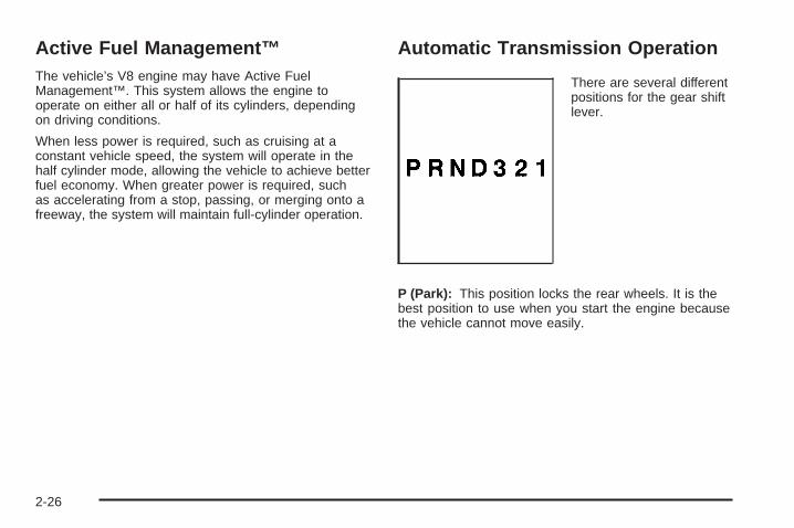
Active Fuel Management™The vehicle’s V8 engine may have Active FuelManagement™. This system allows the engine tooperate on either all or half of its cylinders, dependingon driving conditions.
When less power is required, such as cruising at aconstant vehicle speed, the system will operate in thehalf cylinder mode, allowing the vehicle to achieve betterfuel economy. When greater power is required, suchas accelerating from a stop, passing, or merging onto afreeway, the system will maintain full-cylinder operation.
Automatic Transmission Operation
There are several differentpositions for the gear shiftlever.
P (Park): This position locks the rear wheels. It is thebest position to use when you start the engine becausethe vehicle cannot move easily.
2-26

{CAUTION:
It is dangerous to get out of the vehicle if the shiftlever is not fully in P (Park) with the parking brakefirmly set. The vehicle can roll.
Do not leave the vehicle when the engine isrunning unless you have to. If you have left theengine running, the vehicle can move suddenly.You or others could be injured. To be sure thevehicle will not move, even when you are on fairlylevel ground, always set the parking brake andmove the shift lever to P (Park). See Shifting IntoPark on page 2-35. If you are pulling a trailer, seeTowing a Trailer on page 4-48.
{CAUTION:
If you have four-wheel drive, the vehicle will be freeto roll — even if the shift lever is in P (Park) — if thetransfer case is in Neutral. So, be sure the transfercase is in a drive gear — not in Neutral. SeeFour-Wheel Drive on page 2-30. See Shifting IntoPark on page 2-35.
Make sure the shift lever is fully in P (Park) beforestarting the engine. The vehicle has an automatictransmission shift lock control system. You have to fullyapply the brake pedal, then press the shift leverbutton before you can shift from P (Park) when theignition key is in ON/RUN. If you cannot shift outof P (Park), ease pressure on the shift lever and pushthe shift lever all the way into P (Park) as you maintainbrake application. Then press the shift lever buttonand move the shift lever into another gear. See ShiftingOut of Park on page 2-37.
2-27

R (Reverse): Use this gear to back up.
Notice: Shifting to R (Reverse) while the vehicle ismoving forward could damage the transmission.The repairs would not be covered by the vehiclewarranty. Shift to R (Reverse) only after the vehicleis stopped.
To rock the vehicle back and forth to get out of snow,ice, or sand without damaging the transmission,see If Your Vehicle is Stuck in Sand, Mud, Ice,or Snow on page 4-32.
N (Neutral): In this position, the engine does notconnect with the wheels. To restart the engine whenthe vehicle is already moving, use N (Neutral) only.
{CAUTION:
Shifting into a drive gear while the engine isrunning at high speed is dangerous. Unless yourfoot is firmly on the brake pedal, the vehicle couldmove very rapidly. You could lose control and hitpeople or objects. Do not shift into a drive gearwhile the engine is running at high speed.
Notice: Shifting out of P (Park) or N (Neutral) withthe engine running at high speed may damagethe transmission. The repairs would not be coveredby the vehicle warranty. Be sure the engine isnot running at high speed when shifting the vehicle.
D (Drive): This position is for normal driving.It provides the best fuel economy. If you needmore power for passing, and you are:
• Going less than about 35 mph (55 km/h), push theaccelerator pedal about halfway down.
• Going about 35 mph (55 km/h) or more, push theaccelerator all the way down.
The vehicle will shift down to the next gear and havemore power.
Downshifting the transmission in slippery road conditionscould result in skidding, see “Skidding” under Loss ofControl on page 4-12.
D (Drive) can be used when towing a trailer, carrying aheavy load, driving on steep hills, or for off-roaddriving. You may want to shift the transmission to3 (Third) or, if necessary, a lower gear selection if thetransmission shifts too often.
2-28

3 (Third): This position is also used for normal driving.It reduces vehicle speed more than D (Drive) withoutusing the brakes. You might choose 3 (Third) instead ofD (Drive) when driving on hilly, winding roads, whentowing a trailer, so there is less shifting between gearsand when going down a steep hill.
To shift to the 3 (Third) position, you must first press thelarge button on the shift handle. While the button ispressed, move the shifter in the 3 (Third) position.
2 (Second): This position reduces vehicle speed evenmore than 3 (Third) without using the brakes. Youcan use 2 (Second) on hills. It can help you controlvehicle speed as you go down steep mountain roads,as you use your brakes off and on.
To shift to the 2 (Second) position, you must first pressthe large button on the shift handle. While the buttonis pressed, move the shifter in the 2 (Second) position.
You can also use 2 (Second) for starting the vehiclefrom a stop on slippery road surfaces.
1 (First): This position reduces vehicle speed evenmore than 2 (Second) without using the brakes. Youcan use it on very steep hills, or in deep snow or mud.If the shift lever is put in 1 (First) while the vehicle ismoving forward, the transmission will not shift into firstgear until the vehicle is going slowly enough.
To shift to the 1 (First) position, you must first press thelarge button on the shift handle. While the button ispressed, move the shifter in the 1 (First) position.
Notice: Spinning the tires or holding the vehiclein one place on a hill using only the acceleratorpedal may damage the transmission. The repairwill not be covered by the vehicle warranty. If youare stuck, do not spin the tires. When stopping ona hill, use the brakes to hold the vehicle in place.
2-29
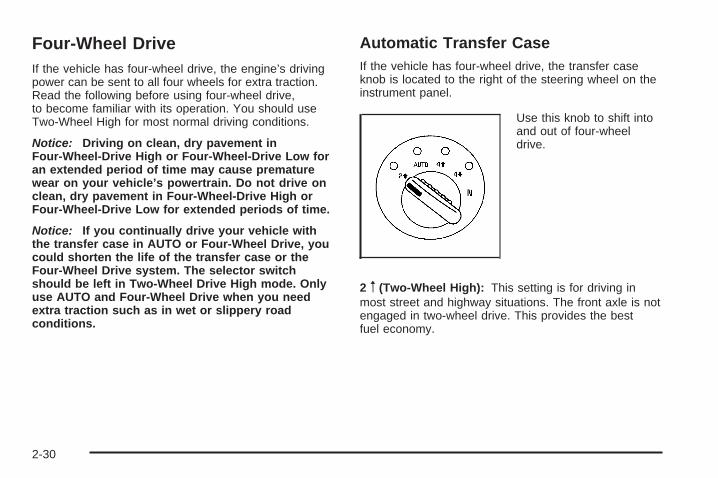
Four-Wheel DriveIf the vehicle has four-wheel drive, the engine’s drivingpower can be sent to all four wheels for extra traction.Read the following before using four-wheel drive,to become familiar with its operation. You should useTwo-Wheel High for most normal driving conditions.
Notice: Driving on clean, dry pavement inFour-Wheel-Drive High or Four-Wheel-Drive Low foran extended period of time may cause prematurewear on your vehicle’s powertrain. Do not drive onclean, dry pavement in Four-Wheel-Drive High orFour-Wheel-Drive Low for extended periods of time.
Notice: If you continually drive your vehicle withthe transfer case in AUTO or Four-Wheel Drive, youcould shorten the life of the transfer case or theFour-Wheel Drive system. The selector switchshould be left in Two-Wheel Drive High mode. Onlyuse AUTO and Four-Wheel Drive when you needextra traction such as in wet or slippery roadconditions.
Automatic Transfer CaseIf the vehicle has four-wheel drive, the transfer caseknob is located to the right of the steering wheel on theinstrument panel.
Use this knob to shift intoand out of four-wheeldrive.
2 m (Two-Wheel High): This setting is for driving inmost street and highway situations. The front axle is notengaged in two-wheel drive. This provides the bestfuel economy.
2-30
AUTO (Automatic Four-Wheel Drive): This setting isideal for use when road conditions are variable.When driving the vehicle in automatic four-wheel drive,the front axle is engaged, but the vehicle’s power issent to the rear wheels. When the vehicle senses aloss of traction, the system will automatically engagefour-wheel drive. Driving in this mode results in slightlylower fuel economy than Two-Wheel High.
4 m (Four-Wheel High): This setting should be usedwhen you need extra traction, such as on snowy or icyroads or in most off-road situations. This setting alsoengages the front axle to help drive the vehicle.
4 n (Four-Wheel Low): This setting also engages thefront axle and delivers extra torque. It sends maximumpower to all four wheels. You might choose thissetting if you are driving off-road in deep sand, deepmud, and climbing or descending steep hills.
{CAUTION:
Shifting the transfer case to Neutral can causethe vehicle to roll even if the transmission is inP (Park). You or someone else could be seriouslyinjured. Be sure to set the parking brake beforeplacing the transfer case in Neutral. See ParkingBrake on page 2-34.
Neutral: Shift the vehicle’s transfer case to Neutral onlywhen towing the vehicle. See Recreational VehicleTowing on page 4-40 for more information.
An indicator light in the knob will show you whichposition the transfer case is in. The indicator lights willcome on briefly when you turn on the ignition andone will stay on. If the lights do not come on, you shouldtake the vehicle to your dealer/retailer for service. Anindicator light will flash while shifting the transfer case.It will stay on when the shift is complete. If thetransfer case cannot make a requested shift, it willreturn to the last chosen setting.
2-31

If the service Four-Wheel Drive Warning Light on theinstrument panel cluster stays on, you should takethe vehicle to your dealer/retailer for service. SeeService Four-Wheel Drive Warning Light on page 3-45for further information.
Shifting Into Four-Wheel High or AutomaticFour-Wheel DriveTurn the knob to Four-Wheel High or AutomaticFour-Wheel Drive. This can be done at any speedunless you are shifting out of Four-Wheel Low.The indicator light will flash while shifting. It willremain on when the shift is complete.
Shifting Into Two-Wheel HighTurn the knob to Two-Wheel High. This can be done atany speed unless you are shifting out of Four-Wheel Low.
Shifting Into Four-Wheel LowTo shift to Four-Wheel Low, the vehicle’s enginemust be running and the vehicle must be stopped ormoving less than 2 mph (3.2 km/h) with the transmissionin N (Neutral). The preferred method for shifting intoFour-Wheel Low is to have your vehicle moving1 or 2 mph (1.6 to 3.2 km/h). Turn the knob toFour-Wheel Low. You must wait for the Four-WheelLow indicator light to stop flashing and stay on beforeshifting the transmission into gear.
If you turn the knob to Four-Wheel Low when thevehicle is in gear and/or moving, the Four-Wheel Lowindicator light will flash for 30 seconds and not completethe shift unless the vehicle is moving less than 2 mph(3.2 km/h) and the transmission is in N (Neutral).After 30 seconds, the transfer case will return to thesetting last chosen.
Shifting Out of Four-Wheel LowTo shift from Four-Wheel Low to Four-Wheel High, AutoFour-Wheel Drive, or Two-Wheel High, the vehicle mustbe stopped or moving less than 2 mph (3.2 km/h) with thetransmission in N (Neutral) and the engine running. Thepreferred method for shifting out of Four-Wheel Low is tohave your vehicle moving 1 or 2 mph (1.6 to 3.2 km/h).Turn the knob to Four-Wheel High, Auto Four-WheelDrive, or Two-Wheel High. You must wait for theFour-Wheel High, Auto Four-Wheel Drive, or Two-WheelHigh indicator light to stop flashing and stay off beforeshifting your transmission into gear.
If the knob is turned to Four Wheel-High, AutoFour-Wheel Drive, or Two-Wheel High when the vehicleis in gear and/or moving, the Four-Wheel High, AutoFour-Wheel Drive, or Two-Wheel High indicator light willflash for 30 seconds. It will not complete the shiftunless the vehicle is moving less than 2 mph (3.2 km/h)with the transmission in N (Neutral).
2-32
Shifting into NeutralBefore shifting the transfer case to Neutral, first makesure the vehicle is parked so that it will not roll.
1. Set the parking brake.
2. Start the vehicle.
3. Put the transmission in N (Neutral).
4. Shift the transfer case to Two-Wheel High.
5. Turn the transfer case knob all of the way pastFour-Wheel Low and hold it there for a minimumof 10 seconds. The Neutral indicator light willcome on.
6. With the engine running, shift the transmissionto R (Reverse) for one second, then shift thetransmission to D (Drive) for one second, toensure that the transfer case is in Neutral.
7. Turn the engine off, by turning the key toACC/ACCESSORY.
8. Place the transmission shift lever in P (Park).
9. Turn the ignition to LOCK/OFF.
Shifting Out of NeutralTo shift the transfer case out of Neutral, do the following:
1. Set the parking brake and apply the regularbrake pedal.
2. Turn the ignition to ON/RUN with the engine off.
3. Put the transmission in N (Neutral).
4. Turn the transfer case knob to the desired position(Two-Wheel High, Four-Wheel High, or AutoFour-Wheel Drive).
5. After the transfer case has shifted out of Neutral,the indicator light will go out.
6. Release the parking brake.
7. Start the engine and shift the transmission to thedesired position.
2-33

Parking Brake
To set the parking brake,hold the regular brakepedal down with your footand pull up on the parkingbrake lever locatedbetween the seats.
To release the parking brake, hold the regular brakepedal down. Pull the parking brake lever up until you canpress in the button at the end of the lever. Hold thebutton in as you move the parking brake lever all theway down.
If the ignition is on, the brake system warning light onthe instrument panel cluster will come on. See BrakeSystem Warning Light on page 3-36.
Notice: Driving with the parking brake on canoverheat the brake system and cause prematurewear or damage to brake system parts. Verify thatthe parking brake is fully released and the brakewarning light is off before driving.
If you are towing a trailer and you must park on a hill,see Towing a Trailer on page 4-48.
2-34
Shifting Into Park
{CAUTION:
It can be dangerous to get out of the vehicle if theshift lever is not fully in P (Park) with the parkingbrake firmly set. The vehicle can roll. If you haveleft the engine running, the vehicle can movesuddenly. You or others could be injured. To besure the vehicle will not move, even when you areon fairly level ground, use the steps that follow.With four-wheel drive, the vehicle will be free toroll — even if the shift lever is in P (Park) — if yourtransfer case is in Neutral. So, be sure the transfercase is in a drive gear — not in Neutral. SeeFour-Wheel Drive on page 2-30. Always put theshift lever fully in P (Park) with the parking brakefirmly set. If you are pulling a trailer, see Towing aTrailer on page 4-48.
To shift into P (Park):
1. Hold the brake pedal down with your foot and setthe parking brake.
2. Move the shift lever into P (Park) by pressing thebutton on the side of the shift lever and pushingthe lever all the way toward the front of the vehicle.
3. Turn the ignition key to OFF/LOCK.
4. Remove the key and take it with you. You know thevehicle is in P (Park) if the key can be removedfrom the ignition.
2-35
Leaving the Vehicle With the EngineRunning
{CAUTION:
It can be dangerous to leave the vehicle with theengine running. The vehicle could move suddenlyif the shift lever is not fully in P (Park) with theparking brake firmly set.
If you have four-wheel drive, the vehicle will befree to roll – even if your lever is in P (Park) – ifthe transfer case is in Neutral. So be sure thetransfer case is in a drive gear – not Neutral.See Four-Wheel Drive on page 2-30.
And, if you leave the vehicle with the enginerunning, it could overheat and even catch fire. Youor others could be injured. Do not leave the vehiclewith the engine running unless you have to.
If you have to leave the vehicle with the engine running,be sure the vehicle is in P (Park) and the parkingbrake is firmly set before you leave it. After you havemoved the shift lever into P (Park), hold the regularbrake pedal down. Then, see if you can move the shiftlever away from P (Park) without first pressing thebutton on the console shift lever. If you can, it meansthat the shift lever was not fully locked into P (Park).
Torque LockIf you are parking on a hill and you do not shift yourtransmission into P (Park) properly, the weight ofthe vehicle may put too much force on the parking pawlin the transmission. You may find it difficult to pull theshift lever out of P (Park). This is called “torque lock.”To prevent torque lock, set the parking brake andthen shift into P (Park) properly before you leave thedriver seat. To find out how, see Shifting Into Parkon page 2-35.
When you are ready to drive, move the shift lever out ofP (Park) before you release the parking brake.
If torque lock does occur, you may need to have anothervehicle push yours a little uphill to take some of thepressure from the parking pawl in the transmission,so you can pull the shift lever out of P (Park).
2-36
Shifting Out of ParkThe vehicle has an electronic shift lock release system.The shift lock release is designed to:
• Prevent ignition key removal unless the shift leveris in P (Park) with the shift lever button fullyreleased, and
• Prevent movement of the shift lever out of P (Park),unless the ignition is in ON/RUN and the regularbrake pedal is applied.
The shift lock release is always functional except in thecase of an uncharged or low voltage (less than 9 volt)battery.
If the vehicle has an uncharged battery or a battery withlow voltage, try charging or jump starting the battery.See Jump Starting on page 5-43 for more information.
To shift out of P (Park) use the following:
1. Apply the brake pedal.
2. Press the shift lever button.
3. Move the shift lever to the desired position.
If you still are unable to shift out of P (Park):
1. Fully release the shift lever button.
2. Hold the brake pedal down and press the shift leverbutton again.
3. Move the shift lever to the desired position.
If you still cannot move the shift lever from P (Park),consult your dealer/retailer or a professional towingservice.
Parking Over Things That Burn
{CAUTION:
Things that can burn could touch hot exhaustparts under the vehicle and ignite. Do not parkover papers, leaves, dry grass, or other things thatcan burn.
2-37

Engine Exhaust
{CAUTION:
Engine exhaust contains Carbon Monoxide (CO)which cannot be seen or smelled. Exposure to COcan cause unconsciousness and even death.
Exhaust may enter the vehicle if:• The vehicle idles in areas with poor ventilation
(parking garages, tunnels, deep snow thatmay block underbody airflow or tail pipes).
• The exhaust smells or sounds strange ordifferent.
• The exhaust system leaks due to corrosion ordamage.
CAUTION: (Continued)
CAUTION: (Continued)
• The vehicle’s exhaust system has beenmodified, damaged or improperly repaired.
• There are holes or openings in the vehiclebody from damage or after-marketmodifications that are not completely sealed.
If unusual fumes are detected or if it is suspectedthat exhaust is coming into the vehicle:
• Drive it only with the windowscompletely down.
• Have the vehicle repaired immediately.
Never park the vehicle with the engine running inan enclosed area such as a garage or a buildingthat has no fresh air ventilation.
2-38

Running the Vehicle While ParkedIt is better not to park with the engine running. But if youever have to, here are some things to know.
{CAUTION:
Idling a vehicle in an enclosed area with poorventilation is dangerous. Engine exhaust mayenter the vehicle. Engine exhaust contains CarbonMonoxide (CO) which cannot be seen or smelled.It can cause unconsciousness and even death.Never run the engine in an enclosed area thathas no fresh air ventilation. For more information,see Engine Exhaust on page 2-38.
{CAUTION:
It can be dangerous to get out of the vehicle if theautomatic transmission shift lever is not fully inP (Park) with the parking brake firmly set.
CAUTION: (Continued)
CAUTION: (Continued)
Thevehicle can roll. Do not leave the vehicle whenthe engine is running unless you have to. If youhave left the engine running, the vehicle can movesuddenly. You or others could be injured. To besure the vehicle will not move, even when you areon fairly level ground, always set the parkingbrake and move the shift lever to P (Park).
{CAUTION:
If the vehicle has four-wheel drive, it will be free toroll — even if the shift lever is in P (Park) — if thetransfer case is in N (Neutral). So be sure thetransfer case is in a drive gear — not in N (Neutral).See Four-Wheel Drive on page 2-30.
Follow the proper steps to be sure the vehicle will notmove. See Shifting Into Park on page 2-35.
If pulling a trailer, see Towing a Trailer on page 4-48.
2-39
Mirrors
Manual Rearview MirrorAdjust the mirror to see clearly behind your vehicle. Holdthe mirror in the center to move it up or down and side toside. The day/night adjustment lets you adjust the mirrorto avoid glare from the lamps behind you. Move thelever to the right for nighttime use and to the left fordaytime use.
Vehicles with OnStar® have three contol buttons locatedat the bottom of the mirror. See your dealer/retailerfor more information on the system and how tosubscribe to OnStar®. See OnStar® System onpage 2-45 for more information on the servicesOnStar® provides.
Automatic Dimming Rearview MirrorThe vehicle may have an automatic-dimming rearviewmirror with a compass and/or temperature display.
See Compass on page 2-42 for more information aboutthe compass display. See “Temperature Display”after in this section.
Vehicles with OnStar® have three control buttonslocated at the bottom of the mirror. See yourdealer/retailer for more information on the system andhow to subscribe to OnStar®. See OnStar® Systemon page 2-45 for more information on the servicesOnStar® provides.
O (On/Off): Press to turn the dimming feature on or off.
TEMP (Temperature): Press to turn the temperaturedisplay on or off.
Automatic Dimming Mirror OperationAutomatic dimming reduces the glare of lights frombehind the vehicle. The dimming feature comes on andthe indicator light illuminates each time the vehicle isstarted.
2-40

Temperature Display
Press O or depending on the mirror, press TEMP toturn the temperature display on or off.
To adjust between Fahrenheit and Celsius:
1. Press and hold O or depending on the mirror,press TEMP until either a flashing F or C appears.
2. Press O or TEMP again to change the display tothe desired unit of measurement. After approximatelyfour seconds of inactivity, the new unit locks in andthe display returns.
If an abnormal temperature reading is displayed foran extended period of time, please consult yourdealer/retailer. Under certain circumstances, a delayin updating the temperature is normal.
Passenger Airbag IndicatorThe vehicle may be equipped with a passenger airbagindicator, on the mirror glass, just above the buttons.If the vehicle has this feature, the mirror displaysthe word ON, or an airbag symbol in Canada, when thepassenger airbag is enabled. For more information,see Passenger Sensing System on page 1-63.
Cleaning the MirrorDo not spray glass cleaner directly on the mirror. Use asoft towel dampened with water.
2-41
Compass
Compass OperationThere is a compass display in the upper right corner ofthe mirror.
Press O or depending on the mirror, press COMP toturn the compass on or off.
Compass CalibrationThe compass may need calibration if:
• After several seconds, the display does not show acompass heading (N for North, for example), theremay be a strong magnetic field interfering withthe compass. Interference can be caused bya magnetic antenna mount, magnetic note padholder or a similar magnetic item.
• The compass does not display the correct headingand the compass zone variance is set correctly.
In order to calibrate, CAL must be displayed in themirror compass windows. If CAL is not displayed, pressand hold O or depending on the mirror, press COMPuntil CAL displays.
The compass can be calibrated by driving the vehicle incircles at 5 mph (8 km/h) or less until the displayreads a direction.
Compass VarianceThe mirror is set to zone eight. If you do not live in zoneeight or drive out of the area, the compass varianceneeds to be changed to the appropriate zone.
2-42
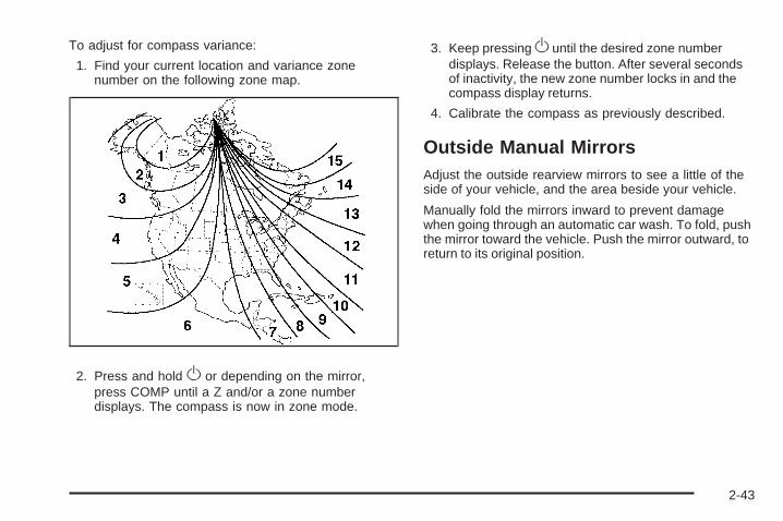
To adjust for compass variance:
1. Find your current location and variance zonenumber on the following zone map.
2. Press and hold O or depending on the mirror,press COMP until a Z and/or a zone numberdisplays. The compass is now in zone mode.
3. Keep pressing O until the desired zone numberdisplays. Release the button. After several secondsof inactivity, the new zone number locks in and thecompass display returns.
4. Calibrate the compass as previously described.
Outside Manual MirrorsAdjust the outside rearview mirrors to see a little of theside of your vehicle, and the area beside your vehicle.
Manually fold the mirrors inward to prevent damagewhen going through an automatic car wash. To fold, pushthe mirror toward the vehicle. Push the mirror outward, toreturn to its original position.
2-43
Outside Power MirrorsVehicles with outside power mirrors have controlslocated on the driver door.
To adjust the mirrors:
1. Turn the control knob left or right to select thedriver’s or passenger mirror.
2. Move the control knob to the left or right or up ordown to position the mirror to see a little of theoutside of the vehicle.
3. After adjusting the position of the mirrors, turn theknob to the center off position so that the mirrorsdo not move.
If the end of travel position in any direction of the mirroris reached, it will enter a ratcheting mode. This actionis harmless. It is a warning that the mirror can gono further. To stop this action, back the mirror up bymoving the knob in the opposite direction.
Manually fold the mirrors inward to prevent damagewhen going through an automatic car wash. Tofold, push the mirrors toward the vehicle. To return themirrors to their original position, push outward.
Outside Convex Mirror
{CAUTION:
A convex mirror can make things (like othervehicles) look farther away than they really are.If you cut too sharply into the right lane, you couldhit a vehicle on the right. Check the inside mirroror glance over your shoulder before changinglanes.
The passenger side mirror is convex shaped. A convexmirror’s surface is curved so more can be seen fromthe driver seat.
Outside Heated Mirrors
< (Rear Window Defogger): Press to heat themirrors. See “Rear Window Defogger” under DualClimate Control System on page 3-20 or Dual AutomaticClimate Control System on page 3-22 for moreinformation.
2-44
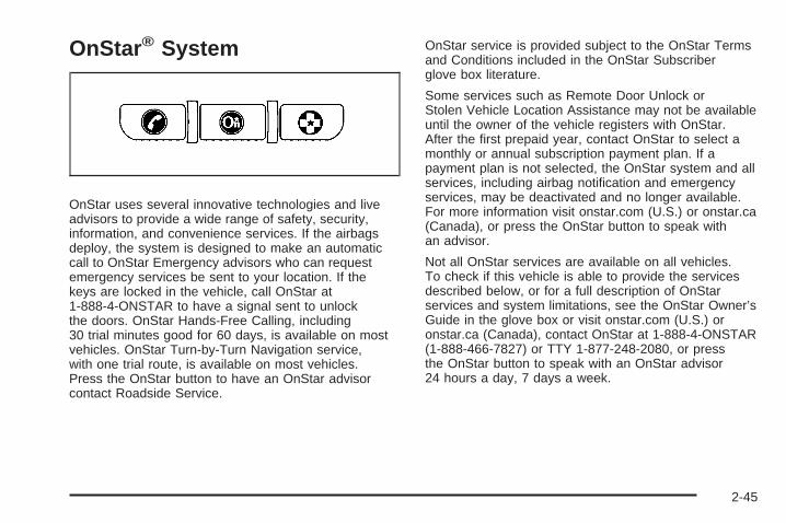
OnStar® System
OnStar uses several innovative technologies and liveadvisors to provide a wide range of safety, security,information, and convenience services. If the airbagsdeploy, the system is designed to make an automaticcall to OnStar Emergency advisors who can requestemergency services be sent to your location. If thekeys are locked in the vehicle, call OnStar at1-888-4-ONSTAR to have a signal sent to unlockthe doors. OnStar Hands-Free Calling, including30 trial minutes good for 60 days, is available on mostvehicles. OnStar Turn-by-Turn Navigation service,with one trial route, is available on most vehicles.Press the OnStar button to have an OnStar advisorcontact Roadside Service.
OnStar service is provided subject to the OnStar Termsand Conditions included in the OnStar Subscriberglove box literature.
Some services such as Remote Door Unlock orStolen Vehicle Location Assistance may not be availableuntil the owner of the vehicle registers with OnStar.After the first prepaid year, contact OnStar to select amonthly or annual subscription payment plan. If apayment plan is not selected, the OnStar system and allservices, including airbag notification and emergencyservices, may be deactivated and no longer available.For more information visit onstar.com (U.S.) or onstar.ca(Canada), or press the OnStar button to speak withan advisor.
Not all OnStar services are available on all vehicles.To check if this vehicle is able to provide the servicesdescribed below, or for a full description of OnStarservices and system limitations, see the OnStar Owner’sGuide in the glove box or visit onstar.com (U.S.) oronstar.ca (Canada), contact OnStar at 1-888-4-ONSTAR(1-888-466-7827) or TTY 1-877-248-2080, or pressthe OnStar button to speak with an OnStar advisor24 hours a day, 7 days a week.
2-45
OnStar Services Available with theSafe & Sound Plan• Automatic Notification of Airbag Deployment
• Advanced Automatic Crash Notification (AACN)(If equipped)
• Link to Emergency Services
• Roadside Assistance
• Stolen Vehicle Location Assistance
• Remote Door Unlock/Vehicle Alert
• OnStar Vehicle Diagnostic Email
• GM Goodwrench On Demand Diagnostics
• OnStar Hands-Free Calling with 30 trial minutes
• OnStar Virtual Advisor (U.S. Only)
OnStar Services Included withDirections & Connections Plan• All Safe and Sound Plan Services
• OnStar Turn-by-Turn Navigation (If equipped) orDriving Directions - Advisor delivered
• RideAssist
• Information and Convenience Services
OnStar Hands-Free CallingOnStar Hands-Free Calling allows eligible OnStarsubscribers to make and receive calls using voicecommands. Hands-Free Calling is fully integrated intothe vehicle, and can be used with OnStar Pre-PaidMinute Packages. Most vehicles include 30 trial minutesgood for 60 days. Hands-Free Calling can also belinked to a Verizon Wireless service plan in the U.S. ora Bell Mobility service plan in Canada, dependingon eligibility. To find out more, refer to the OnStarOwner’s Guide in the vehicle’s glove box, visitonstar.com or onstar.ca, or speak with an OnStaradvisor by pressing the OnStar button or calling1-888-4-ONSTAR (1-888-466-7827).
OnStar Turn-by-Turn NavigationVehicles with the OnStar Turn-by-Turn Navigationsystem can provide voice-guided driving directions.Press the OnStar button to have an OnStar advisorlocate a business or address and download drivingdirections to the vehicle. Voice-guided directions to thedesired destination will play through the audio systemspeakers. See the OnStar Owner’s Guide for moreinformation.
2-46
OnStar Virtual AdvisorOnStar Virtual Advisor is a feature of OnStarHands-Free Calling that uses minutes to accesslocation-based weather, local traffic reports, andstock quotes. Press the phone button and give afew simple voice commands to browse through thevarious topics. See the OnStar Owner’s Guide formore information. This feature is only available in thecontinental U.S.
OnStar Steering Wheel ControlsThis vehicle may have a Talk/Mute button that canbe used to interact with OnStar Hands-Free Calling.See Audio Steering Wheel Controls on page 3-109 formore information.
On some vehicles, the mute button can be used to dialnumbers into voice mail systems, or to dial phoneextensions. See the OnStar Owner’s Guide for moreinformation.
How OnStar Service WorksThe OnStar system can record and transmit vehicleinformation. This information is automatically sent to anOnStar Call Center when the OnStar button is pressed,the emergency button is pressed, or if the airbags orAACN system deploy. This information usually includesthe vehicle’s GPS location and, in the event of a crash,additional information regarding the crash that the vehiclewas involved in (e.g. the direction from which the vehiclewas hit). When the Virtual Advisor feature of OnStarHands-Free Calling is used, the vehicle also sendsOnStar the vehicle’s GPS location so they can provideservices where it is located.
OnStar service cannot work unless the vehicle is in aplace where OnStar has an agreement with a wirelessservice provider for service in that area. OnStar servicealso cannot work unless the vehicle is in a place wherethe wireless service provider OnStar has hired for thatarea has coverage, network capacity and reception whenthe service is needed, and technology that is compatiblewith the OnStar service. Not all services are availableeverywhere, particularly in remote or enclosed areas, orat all times.
2-47

Location information about the vehicle is only availableif the GPS satellite signals are unobstructed andavailable.
The vehicle must have a working electrical system,including adequate battery power, for the OnStarequipment to operate. There are other problems OnStarcannot control that may prevent OnStar from providingOnStar service at any particular time or place. Someexamples are damage to important parts of the vehiclein a crash, hills, tall buildings, tunnels, weather orwireless phone network congestion.
Your ResponsibilityIncrease the volume of the radio if the OnStar advisorcannot be heard. If the light next to the OnStar buttons isred, the system may not be functioning properly. Pressthe OnStar button and request a vehicle diagnostic. If thelight appears clear (no light is appearing), your OnStarsubscription has expired and all services have beendeactivated. Press the OnStar button to confirm that theOnStar equipment is active.
Universal Home RemoteSystemThe Universal Home Remote System provides a way toreplace up to three hand-held Radio-Frequency (RF)transmitters used to activate devices such as garagedoor openers, security systems, and home lighting.
This device complies with Part 15 of the FCC Rules.Operation is subject to the following two conditions:
1. This device may not cause harmful interference.
2. This device must accept any interference received,including interference that may cause undesiredoperation.
This device complies with RSS-210 of Industry Canada.Operation is subject to the following two conditions:
1. This device may not cause interference.
2. This device must accept any interference received,including interference that may cause undesiredoperation of the device.
Changes or modifications to this system by other thanan authorized service facility could void authorization touse this equipment.
2-48
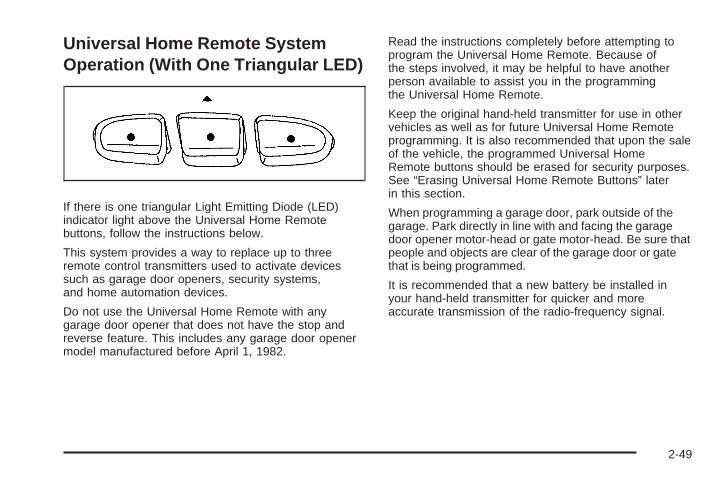
Universal Home Remote SystemOperation (With One Triangular LED)
If there is one triangular Light Emitting Diode (LED)indicator light above the Universal Home Remotebuttons, follow the instructions below.
This system provides a way to replace up to threeremote control transmitters used to activate devicessuch as garage door openers, security systems,and home automation devices.
Do not use the Universal Home Remote with anygarage door opener that does not have the stop andreverse feature. This includes any garage door openermodel manufactured before April 1, 1982.
Read the instructions completely before attempting toprogram the Universal Home Remote. Because ofthe steps involved, it may be helpful to have anotherperson available to assist you in the programmingthe Universal Home Remote.
Keep the original hand-held transmitter for use in othervehicles as well as for future Universal Home Remoteprogramming. It is also recommended that upon the saleof the vehicle, the programmed Universal HomeRemote buttons should be erased for security purposes.See “Erasing Universal Home Remote Buttons” laterin this section.
When programming a garage door, park outside of thegarage. Park directly in line with and facing the garagedoor opener motor-head or gate motor-head. Be sure thatpeople and objects are clear of the garage door or gatethat is being programmed.
It is recommended that a new battery be installed inyour hand-held transmitter for quicker and moreaccurate transmission of the radio-frequency signal.
2-49

Programming the Universal HomeRemote SystemFor questions or help programming the UniversalHome Remote System, call 1-800-355-3515 or go towww.homelink.com.
Programming a garage door opener involvestime-sensitive actions, so read the entire procedurebefore starting. Otherwise, the device will time outand the procedure will have to be repeated.
To program up to three devices:
1. From inside the vehicle, press and hold down thetwo outside buttons at the same time, releasingonly when the Universal Home Remote indicatorlight begins to flash, after 20 seconds. This stepwill erase the factory settings or all previouslyprogrammed buttons.
Do not hold down the buttons for longer than30 seconds and do not repeat this step to programthe remaining two Universal Home Remotebuttons.
2. Hold the end of your hand-held transmitter about1 to 3 inches (3 to 8 cm) away from the UniversalHome Remote buttons while keeping the indicatorlight in view. The hand-held transmitter was suppliedby the manufacturer of your garage door openerreceiver (motor head unit).
3. At the same time, press and hold both the UniversalHome Remote button to be used to control thegarage door and the hand-held transmitter button.Do not release the Universal Home Remotebutton or the hand-held transmitter button untilStep 4 has been completed.Some entry gates and garage door openers mayrequire substitution of Step 3 with the procedurenoted in “Gate Operator and CanadianProgramming” later in this section.
4. The indicator light on the Universal Home Remotewill flash slowly at first and then rapidly afterUniversal Home Remote successfully receives thefrequency signal from the hand-held transmitter.Release both buttons.
2-50
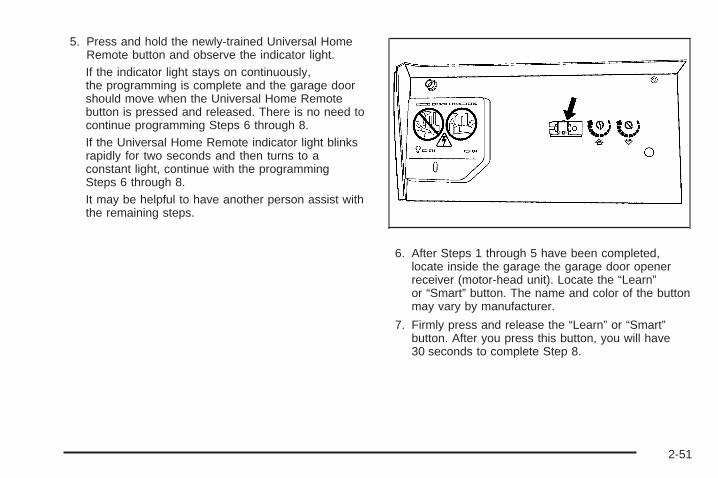
5. Press and hold the newly-trained Universal HomeRemote button and observe the indicator light.If the indicator light stays on continuously,the programming is complete and the garage doorshould move when the Universal Home Remotebutton is pressed and released. There is no need tocontinue programming Steps 6 through 8.If the Universal Home Remote indicator light blinksrapidly for two seconds and then turns to aconstant light, continue with the programmingSteps 6 through 8.It may be helpful to have another person assist withthe remaining steps.
6. After Steps 1 through 5 have been completed,locate inside the garage the garage door openerreceiver (motor-head unit). Locate the “Learn”or “Smart” button. The name and color of the buttonmay vary by manufacturer.
7. Firmly press and release the “Learn” or “Smart”button. After you press this button, you will have30 seconds to complete Step 8.
2-51
8. Immediately return to the vehicle. Firmly press andhold the Universal Home Remote button, chosen inStep 3 to control the garage door, for two seconds,and then release it. If the garage door does notmove, press and hold the same button a second timefor two seconds, and then release it. Again, if thedoor does not move, press and hold the same buttona third time for two seconds, and then release.The Universal Home Remote should now activatethe garage door.
To program the remaining two Universal Home Remotebuttons, begin with Step 2 of “Programming theUniversal Home Remote System.” Do not repeat Step 1,as this will erase all previous programming from theUniversal Home Remote buttons.
Gate Operator and CanadianProgrammingIf you have questions or need help programming theUniversal Home Remote System, call 1-800-355-3515 orgo to www.homelink.com.
Canadian radio-frequency laws require transmittersignals to time out or quit after several seconds oftransmission. This may not be long enough for UniversalHome Remote to pick up the signal during programming.Similarly, some U.S. gate operators are manufacturedto time out in the same manner.
If you live in Canada, or you are having difficultyprogramming a gate operator or garage door opener byusing the “Programming Universal Home Remote”procedures, regardless of where you live, replaceStep 3 under “Programming Universal Home Remote”with the following:
Continue to press and hold the Universal Home Remotebutton while you press and release every two seconds(cycle) the hand-held transmitter button until thefrequency signal has been successfully accepted by theUniversal Home Remote. The Universal Home Remoteindicator light will flash slowly at first and then rapidly.Proceed with Step 4 under “Programming UniversalHome Remote” to complete.
2-52

Using Universal Home RemotePress and hold the appropriate Universal Home Remotebutton for at least half of a second. The indicator lightwill come on while the signal is being transmitted.
Erasing Universal Home RemoteButtonsThe programmed buttons should be erased when thevehicle is sold or the lease ends.
To erase all programmed buttons on the UniversalHome Remote device:
1. Press and hold down the two outside buttons untilthe indicator light begins to flash, after 20 seconds.
2. Release both buttons.
Reprogramming a Single UniversalHome Remote ButtonTo reprogram any of the three Universal Home Remotebuttons, repeat the programming instructions earlierin this section, beginning with Step 2.
For help or information on the Universal Home RemoteSystem, call the customer assistance phone numberunder Customer Assistance Offices on page 7-6.
Storage Areas
Glove BoxLift the glove box handle up to open it. Use the key tolock and unlock the glove box.
Overhead ConsoleYour vehicle may have this feature. The overheadconsole may include reading lamps, a UniversalHome Remote and a sunroof switch. See Sunroofon page 2-57 and Universal Home Remote Systemon page 2-48 for more information.
2-53
Center Console StoragePull the front lever on the center console while lifting thetop to open it.
The console has cupholders on the front and rear of thestorage compartment.
The console may also contain:
• Rear Seat Audio Controls
• Rear Seat Accessory Power Outlets
• Rear Climate Control
To open the center armrest compartment, lift the coverby pulling up on the latch handle located under thefront edge of the armrest.
Luggage Carrier
{CAUTION:
If something is carried on top of the vehicle that islonger or wider than the luggage carrier — likepaneling, plywood, or a mattress— the wind cancatch it while the vehicle is being driven. This cancause a driver to lose control. The item beingcarried could be violently torn off, and this couldcause a collision, and damage the vehicle. Itemsmay be carried inside. Never carry somethinglonger or wider than the luggage carrier on top ofthe vehicle.
If your vehicle has a luggage carrier, it will allow youto load things on top of your vehicle. The luggage carrierhas side rails attached to the roof, places to use fortying things down and may have sliding crossrails.These let you load some other things on top of yourvehicle, as long as they are not wider or longer than theluggage carrier.
2-54

To slide the crossrails to where you want them, pull upon the lever on each side of the crossrail. Thisreleases the crossrail and allows you to slide it. Whenthe crossrail is where you want it, press down onthe levers to lock it into place.
Notice: Loading cargo on the luggage carrier thatweighs more than 220 lbs (100 kg) or hangs over therear or sides of the vehicle may damage yourvehicle. Load cargo so that it rests on the slats asfar forward as possible and against the siderails, making sure to fasten it securely.
Do not exceed the maximum vehicle capacity whenloading your vehicle. For more information on vehiclecapacity and loading, see Loading the Vehicle onpage 4-33.
To prevent damage or loss of cargo as you are driving,check now and then to make sure the luggage carrieris locked and cargo is still securely fastened.
When the luggage carrier is not in use, place thecrossrails at the following positions for wind noisereduction. Place one crossrail at the rear most point ofthe vehicle and the other crossrail above the openingof the rear door.
Rear Floor Storage Cover
{CAUTION:
If any removable convenience item is not securedproperly, it can move around in a collision orsudden stop. People in the vehicle could beinjured. Be sure to secure any such item properly.
The vehicle has a rear cargo area with a removablestorage cover.
To remove the rear floor storage cover, do the following:
1. Press the latch release and lift up the latchhandle.
2. Raise the cover slightly to unhook it.
3. Pull the cover towards the rear of the vehicle torelease it from the forward mounting slots.
To reinstall the rear floor storage cover, reverse theprevious steps. Make sure the cover is secure byapplying slight pressure to the latch until it clicks.
2-55

Convenience NetFor vehicles with a convenience net located in the rear,use it to store small loads as far forward as possible.The net should not be used to store heavy loads.
Cargo CoverIf your vehicle has a cargo cover, you can use it tocover items in the cargo area of your vehicle.
To install the cargo cover:
1. Align the endcap with the pocket in the trim panellocated behind the rear seat.
2. Squeeze the opposite endcap, align it with thepocket located on the opposite side of the trimpanel and release.
3. Grasp the handle and unroll the cover.
4. Latch the posts into the sockets on the inside of thevehicle to secure it.
To remove the cargo cover, do the following:
1. Release the cover from the latch posts and carefullyroll it back up.
2. Squeeze one endcap and remove it from thepocket in the trim panel.
3. Remove the cargo cover from the other endcap sothat you can remove the shade from the vehicle.
{CAUTION:
An improperly stored cargo cover could be thrownabout the vehicle during a collision or suddenmaneuver. Someone could be injured. If the coveris removed, always store it in the proper storagelocation. When it is replaced, always be sure thatit is securely reattached.
2-56

Cargo Tie DownsFour cargo tie-downs are located in the rear compartmentof the vehicle. The tie-downs can be used to secure smallloads.
SunroofThe vehicle may have a power sliding sunroof. To openor close the sunroof, the ignition must be turned toON/RUN, ACC/ACCESSORY, or Retained AccessoryPower (RAP) must be active. See Retained AccessoryPower (RAP) on page 2-23.
Press and release theback of the control in theoverhead console toopen the sunroof. Pressthe front of the controlto close the sunroof.
Once the sunroof is closed, press the forward side ofthe control to open the sunroof to the vent position.
The sunroof has a sunshade which can be pulledforward to block sun rays. If it is in the closed position, itwill open when the sunroof opens.
Do not keep the sunroof open for long periods of timewhile the vehicle is not in use. Debris can collect inthe tracks, damage the sunroof operation and plug thewater draining system.
2-57

✍ NOTES
2-58

Instrument Panel Overview ...............................3-4Hazard Warning Flashers ................................3-6Horn .............................................................3-6Tilt Wheel .....................................................3-6Turn Signal/Multifunction Lever .........................3-7Turn and Lane-Change Signals ........................3-7Headlamp High/Low-Beam Changer ..................3-8Flash-to-Pass .................................................3-8Windshield Wipers ..........................................3-9Windshield Washer .........................................3-9Rear Window Wiper/Washer ...........................3-10Cruise Control ..............................................3-10Headlamps ..................................................3-13Headlamps on Reminder ................................3-14Daytime Running Lamps (DRL) .......................3-14Automatic Headlamp System ..........................3-15Fog Lamps ..................................................3-16Instrument Panel Brightness ...........................3-16Dome Lamps ...............................................3-17Dome Lamp Override ....................................3-17Entry Lighting ...............................................3-17Exit Lighting .................................................3-17Reading Lamps ............................................3-17Electric Power Management ...........................3-18Battery Run-Down Protection ..........................3-18Accessory Power Outlet(s) .............................3-19Ashtray(s) and Cigarette Lighter ......................3-19
Climate Controls ............................................3-20Dual Climate Control System ..........................3-20Dual Automatic Climate Control System ...........3-22Outlet Adjustment .........................................3-26Rear Climate Control System .........................3-27
Warning Lights, Gages, and Indicators ............3-28Instrument Panel Cluster ................................3-29Speedometer and Odometer ...........................3-30Trip Odometer ..............................................3-30Tachometer .................................................3-30Safety Belt Reminders ...................................3-31Airbag Readiness Light ..................................3-32Passenger Airbag Status Indicator ...................3-33Charging System Light ..................................3-34Voltmeter Gage ............................................3-35Brake System Warning Light ..........................3-36Antilock Brake System (ABS) Warning Light .....3-37StabiliTrak® Service Light ...............................3-37StabiliTrak® Indicator Light .............................3-38Engine Coolant Temperature Gage ..................3-38Tire Pressure Light .......................................3-39Malfunction Indicator Lamp .............................3-39Oil Pressure Gage ........................................3-42Change Engine Oil Light ................................3-43
Section 3 Instrument Panel
3-1
Security Light ...............................................3-44Cruise Control Light ......................................3-44Reduced Engine Power Light .........................3-44Highbeam On Light .......................................3-45Service Four-Wheel Drive Warning Light ..........3-45Check Gages Warning Light ...........................3-45Gate Ajar Light .............................................3-46Fuel Gage ...................................................3-46Low Fuel Warning Light .................................3-47Check Gas Cap Light ....................................3-47
Driver Information Center (DIC) .......................3-47DIC Operation and Displays ...........................3-48DIC Warnings and Messages .........................3-51DIC Vehicle Customization .............................3-56
Audio System(s) .............................................3-62Setting the Clock ..........................................3-63Radio(s) ......................................................3-64Using an MP3 ..............................................3-80XM Radio Messages .....................................3-84Navigation/Radio System ...............................3-85Bluetooth® ...................................................3-85Rear Seat Entertainment (RSE) System ...........3-96Rear Seat Audio (RSA) ................................3-108Theft-Deterrent Feature ................................3-109Audio Steering Wheel Controls ......................3-109Radio Reception .........................................3-110Fixed Mast Antenna ....................................3-111XM™ Satellite Radio Antenna System ............3-111Chime Level Adjustment ...............................3-111
Section 3 Instrument Panel
3-2

✍ NOTES
3-3
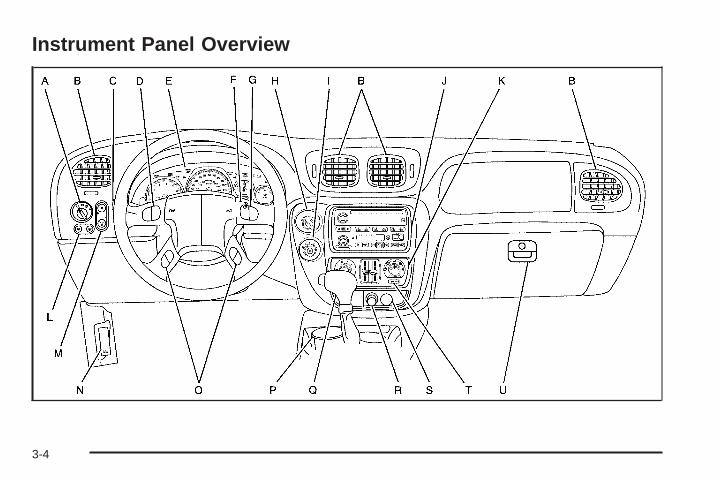
Instrument Panel Overview
3-4

The main components of the instrument panel are the following:
A. Headlamps on page 3-13.B. Air Outlets. See Outlet Adjustment on page 3-26.C. Turn Signal/Multifunction Lever on page 3-7.D. OnStar® and Audio Steering Wheel Controls on
page 3-109 (If Equipped).E. Instrument Panel Cluster on page 3-29.F. Ignition Positions on page 2-22.G. Audio Steering Wheel Controls on page 3-109
(If Equipped).H. Transfer Case Controls. See “Automatic Transfer
Case” under Four-Wheel Drive on page 2-30.I. Rear Window Washer/Wiper. See Windshield
Washer on page 3-9.J. Audio System(s) on page 3-62.K. Dual Climate Control System on page 3-20.L. Dome Lamp Override on page 3-17.M. Fog Lamps on page 3-16 (If Equipped).
Instrument Panel Brightness on page 3-16.
N. Hood Release on page 5-11.O. Driver Information Center (DIC) Steering Wheel
Controls (If Equipped). See Driver InformationCenter (DIC) on page 3-47.
P. Ashtray. See Ashtray(s) and Cigarette Lighter onpage 3-19.
Q. Shift Lever and StabiliTrak® Button. See ShiftingInto Park on page 2-35 and StabiliTrak® Systemon page 4-6.
R. Lighter. See Ashtray(s) and Cigarette Lighter onpage 3-19.
S. Accessory Power Outlet(s) on page 3-19.T. Rear Window Defogger. See “Rear Window
Defogger” under Dual Climate Control System onpage 3-20 and Dual Automatic Climate ControlSystem on page 3-22.
U. Glove Box on page 2-53.
3-5
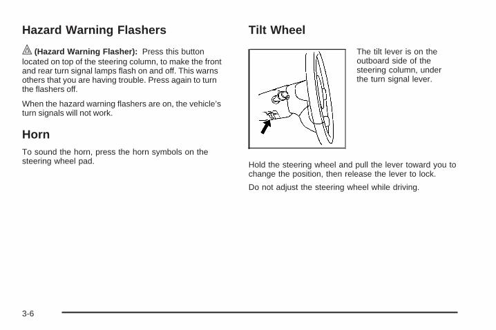
Hazard Warning Flashers
| (Hazard Warning Flasher): Press this buttonlocated on top of the steering column, to make the frontand rear turn signal lamps flash on and off. This warnsothers that you are having trouble. Press again to turnthe flashers off.
When the hazard warning flashers are on, the vehicle’sturn signals will not work.
HornTo sound the horn, press the horn symbols on thesteering wheel pad.
Tilt Wheel
The tilt lever is on theoutboard side of thesteering column, underthe turn signal lever.
Hold the steering wheel and pull the lever toward you tochange the position, then release the lever to lock.
Do not adjust the steering wheel while driving.
3-6

Turn Signal/Multifunction Lever
The lever on the left side of the steering columnincludes the following:
• G Turn and Lane Change Signals
• 23 Headlamp High/Low-Beam Changer
• Flash-to-Pass Feature
• N Windshield Wipers
• J Windshield Washer
• I Cruise Control
Turn and Lane-Change Signals
An arrow on the instrumentpanel cluster flashes in thedirection of the turn orlane change.
Move the lever all the way up or down to signal a turn.Raise or lower the lever until the arrow starts to flashto signal a lane change. Hold it there until the lanechange is complete.The lever returns to its starting position when it isreleased.If after signaling a turn or lane change the arrowsflash rapidly or do not come on, a signal bulb could beburned out.Have the bulbs replaced. If the bulb is not burned out,check the fuse. See Fuses and Circuit Breakers onpage 5-119.If the vehicle has a trailer towing option with addedwiring for the trailer lamps, a turn signal flasher is used.With this flasher installed, the signal indicator flasheseven if a turn signal bulb is burned out. Check the frontand rear turn signal lamps regularly to make sure theyare working.
3-7

Turn Signal On ChimeA chime sounds if the turn signal has been on3/4 of a mile (1.2 km). Move the turn signal lever to off.
Headlamp High/Low-Beam ChangerTo change the headlamps from low to high beam,push the lever toward the instrument panel. To returnto low-beam headlamps, pull the multifunction levertoward you. Then release it.
When the high beams areon, this indicator light onthe instrument panel clusterwill also be on.
Flash-to-PassThis feature lets high-beam headlamps be used tosignal to a driver in front of you that you want to pass.It works even if the headlamps are in the automaticposition.
To use it, pull the turn signal lever toward you, thenrelease it.
If the headlamps are in the automatic position or onlow beam, the high-beam headlamps turn on. Theywill stay on as long as the lever is held toward you.The high-beam indicator on the instrument panelcluster comes on. Release the lever to return tonormal operation.
3-8
Windshield Wipers
8 (Mist): Turn the band to mist, for a single wipingcycle. Hold it there until the wipers start, then release it.The wipers will stop after one wipe. Hold the band onmist longer if more wipe cycles are needed.
9 (Off): Turns the wipers off.
N (Windshield Wipers): Turn the band to control thewindshield wipers.
6 : Turn the band to set the wiper speed for a long orshort delay between wipes. The closer to the top of thelever, the shorter the delay time.
For steady wiping at low speed, turn the band awayfrom you to the first solid band past the delay settings.For high-speed wiping, turn the band further, to thesecond solid band past the delay settings.
Be sure to clear ice and snow from the wiper bladesbefore using them. If they are frozen to the windshield,gently loosen or thaw them. If they become worn ordamaged, get new blades or blade inserts.
Windshield Washer
L (Windshield Washer): Press the windshieldwasher paddle to spray washer fluid on the windshield.The wipers will clear the window and then eitherstop or return to the preset speed.
{CAUTION:
In freezing weather, do not use your washer untilthe windshield is warmed. Otherwise the washerfluid can form ice on the windshield, blocking yourvision.
3-9
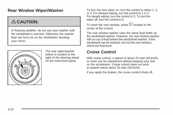
Rear Window Wiper/Washer
{CAUTION:
In freezing weather, do not use your washer untilthe windshield is warmed. Otherwise the washerfluid can form ice on the windshield, blockingyour vision.
The rear wiper/washerbutton is located to theright of the steering wheelon the instrument panel.
To turn the rear wiper on, turn the control to either 1, 2,or 3. For delayed wiping, turn the control to 1 or 2.For steady wiping, turn the control to 3. To turn thewiper off, turn the control to 0.
To wash the rear window, press = located in thecenter of the control.
The rear window washer uses the same fluid bottle asthe windshield washer. However, the rear window washerwill run out of fluid before the windshield washer. If thewindshield can be washed, but not the rear window,check the fluid level.
Cruise ControlWith cruise control, a speed of about 25 mph (40 km/h)or more can be maintained without keeping your footon the accelerator. Cruise control does not workat speeds below about 25 mph (40 km/h).
If you apply the brakes, the cruise control shuts off.
3-10
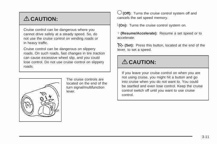
{CAUTION:
Cruise control can be dangerous where youcannot drive safely at a steady speed. So, donot use the cruise control on winding roads orin heavy traffic.
Cruise control can be dangerous on slipperyroads. On such roads, fast changes in tire tractioncan cause excessive wheel slip, and you couldlose control. Do not use cruise control on slipperyroads.
The cruise controls arelocated on the end of theturn signal/multifunctionlever.
9 (Off): Turns the cruise control system off andcancels the set speed memory.
R (On): Turns the cruise control system on.
S (Resume/Accelerate): Resume a set speed or toaccelerate.
T (Set): Press this button, located at the end of thelever, to set a speed.
{CAUTION:
If you leave your cruise control on when you arenot using cruise, you might hit a button and gointo cruise when you do not want to. You couldbe startled and even lose control. Keep the cruisecontrol switch off until you want to use cruisecontrol.
3-11

Setting Cruise Control
1. Move the cruise control switch to R .
2. Get up to the desired speed.
3. Press T at the end of the lever and release it.
4. Take your foot off the accelerator pedal.
Some vehicles havea cruise light on theinstrument panel clusterthat will come on when thecruise control is engaged.
Resuming a Set SpeedIf the cruise control is set at a desired speed and thenthe brake is applied, this shuts off the cruise control.But it does not need to be reset.
Once the vehicle is going about 25 mph (40 km/h) ormore, move the cruise control switch briefly from R to S .
The vehicle returns to the previously chosen speedand stays there.
If the switch is held on resume/accelerate, the vehiclekeeps going faster until the switch is released orthe brakes are applied. So unless you want the vehicleto go faster, do not hold the switch at resume/accelerate.
Increasing Speed While Using CruiseControlThere are two ways to go to a higher speed:
• Use the accelerator pedal to get to the desiredspeed. Press T at the end of the lever, thenrelease the button and the accelerator pedal.The vehicle will now cruise at the higher speed.
• Move the cruise switch from R to S . Hold it thereuntil the vehicle reaches the desired speed andthen release the switch. To increase the vehiclespeed in small amounts, move the switch brieflyto resume/accelerate. Each time this is done,the vehicle goes about 1 mph (1.6 km/h) faster.
Reducing Speed While Using CruiseControl
Press T at the end of the lever until the desiredspeed is reached, then release it. Each time this isdone, the vehicle goes about 1 mph (1.6 km/h) slower.
3-12

Passing Another Vehicle While UsingCruise ControlUse the accelerator pedal to increase the vehicle speed.When you take your foot off the pedal, the vehicle willslow down to the cruise control speed set earlier.
Using Cruise Control on HillsHow well the cruise control works on hills depends uponthe vehicle speed, load and the steepness of the hills.When going up steep hills, you may want to step on theaccelerator pedal to maintain your speed. When goingdownhill, you may have to brake or shift to a lower gear tokeep your speed down. When the brakes are applied thecruise control will disengage.
Ending Cruise ControlThere are three ways to turn off the cruise control:
• Step lightly on the brake pedal.
• Move the cruise switch to 9 .
• Shift the transmission to N (Neutral).
Erasing Speed MemoryThe cruise control set speed memory is erased whenthe cruise control or the ignition is turned off.
Headlamps
The exterior lamps knob islocated on the instrumentpanel.
c (Off): Turn the knob to this symbol and releaseit to turn off the Daytime Running Lamps (DRL) and theAutomatic Headlamps (AHS). An indicator is lit when theposition is selected. This position is not available forvehicles first sold in Canada.
? (Automatic DRL/AHS): Places the system intoautomatic headlamp mode.
3-13

; (Parking Lamps): Turns on the parking lamps,as well as the following:
• Sidemarker Lamps
• Taillamps
• License Plate Lamps
• Instrument Panel Lights
2 (Headlamps): Turns on the headlamps, as well asthe following:
• Parking Lamps
• Sidemarker Lamps
• Taillamps
• License Plate Lamps
• Instrument Panel Lights
Headlamps on ReminderA reminder tone sounds when the headlamps or parkinglamps are manually turned on, if the driver’s door is openand the ignition is in LOCK/OFF or ACC/ACCESSORY.To turn the tone off, turn the knob all the waycounterclockwise.
In the automatic mode, the headlamps turn off once theignition key is in LOCK/OFF.
Daytime Running Lamps (DRL)Daytime Running Lamps (DRL) can make it easierfor others to see the front of your vehicle during the day.Fully functional DRL are required on all vehicles firstsold in Canada.
The DRL system makes the headlamps come on atreduced brightness when the following conditionsare met:
• The ignition is on.
• The exterior lamps knob is in automaticheadlamp mode.
• The light sensor detects daytime light.
• The transmission is not in P (Park).
When the DRL are on, only the headlamps will be on.The taillamps, sidemarker, instrument panel lightsand other lamps will not be on.
When it begins to get dark, the headlamps automaticallyswitch from DRL to the regular headlamps.
3-14
Automatic Headlamp SystemWhen it is dark enough outside, the AutomaticHeadlamp System turns on the headlamps when thevehicle is started and after the transmission has beenshifted out of the P (Park) position. The headlamps,taillamps, sidemarker, and parking lamps will come on.The instrument panel lights and radio lights will also turnon at normal brightness. Once on, the system remains onduring these conditions even if the vehicle is shifted backinto P (Park).
The vehicle has a light sensor on the top of theinstrument panel. Do not cover the sensor or thesystem may come on whenever the ignition is onand the vehicle is shifted out of the P (Park) position.
The system could also turn on the lamps when drivingthrough a parking garage, heavy overcast weatheror a tunnel. This is normal.
There is a delay in the transition between the daytimeand nighttime operation of the Daytime Running Lamps(DRL) and the automatic headlamp systems, so that
driving under bridges or bright overhead street lights doesnot affect the system. The DRL and automatic headlampsystem are only affected when the light sensor sees achange in lighting lasting longer than the delay.
If the vehicle is started in a dark garage, the automaticheadlamp system comes on after the transmissionis shifted out of P (Park). Once the vehicle leaves thegarage, it takes about one minute for the automaticheadlamp system to change to DRL if it is light outside.During that delay, the instrument panel cluster mightnot be as bright as usual. Make sure the instrumentpanel brightness control is in the full bright position.
If the vehicle is running and the automatic headlampsystem is already on, it can be turned off by turningand releasing the headlamp control at the off position.The automatic headlamp system stays off until youturn and release the headlamp control at the off positionagain. See Headlamps on page 3-13.
3-15
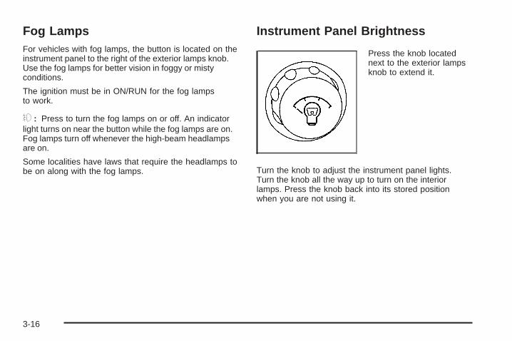
Fog LampsFor vehicles with fog lamps, the button is located on theinstrument panel to the right of the exterior lamps knob.Use the fog lamps for better vision in foggy or mistyconditions.
The ignition must be in ON/RUN for the fog lampsto work.
# : Press to turn the fog lamps on or off. An indicatorlight turns on near the button while the fog lamps are on.Fog lamps turn off whenever the high-beam headlampsare on.
Some localities have laws that require the headlamps tobe on along with the fog lamps.
Instrument Panel Brightness
Press the knob locatednext to the exterior lampsknob to extend it.
Turn the knob to adjust the instrument panel lights.Turn the knob all the way up to turn on the interiorlamps. Press the knob back into its stored positionwhen you are not using it.
3-16
Dome LampsThe dome lamps come on when a door is opened,unless the dome lamp override button is pressed in.
Dome Lamp OverrideThe dome override button is located below the exteriorlamps knob.
E : Press to turn the dome lamps off. The domelamps will remain off when a door is open. Thisoverrides the illuminated entry feature unless theRemote Keyless Entry (RKE) transmitter is usedto unlock the vehicle.
Press the button again to return the lamps to automaticoperation. The dome lamps will come on when adoor is opened.
Entry LightingThe vehicle has entry lighting.
When any door is opened, the dome lamps comeon as long as the dome override lamp override buttonis not pressed in. When all the doors are closed, thelamps stay on for a short period of time and then turn offautomatically. If you use the Remote Keyless Entry (RKE)transmitter to unlock the vehicle, the interior lamps comeon for a short time whether or not the dome lamp overrideis on.
Exit LightingWith exit lighting, the interior lamps come on when youremove the key from the ignition. If the dome overrideis off, these lamps stay on for a short period of timeand then go out.
Reading LampsThe reading lamps are located in the front console.
Press the lens on the lamps to turn the reading lampson or off.
3-17
Electric Power ManagementThe vehicle has Electric Power Management (EPM) thatestimates the battery’s temperature and state of charge.It then adjusts the voltage for best performance andextended life of the battery.
When the battery’s state of charge is low, the voltage israised slightly to quickly bring the charge back up. Whenthe state of charge is high, the voltage is lowered slightlyto prevent overcharging. If the vehicle has a voltmetergage or a voltage display on the Driver InformationCenter (DIC), you may see the voltage move up ordown. This is normal. If there is a problem, an alertwill be displayed.
The battery can be discharged at idle if the electricalloads are very high. This is true for all vehicles. This isbecause the generator (alternator) may not be spinningfast enough at idle to produce all the power that isneeded for very high electrical loads.
A high electrical load occurs when several of thefollowing are on, such as: headlamps, high beams,fog lamps, rear window defogger, climate control fan athigh speed, heated seats, engine cooling fans, trailerloads, and loads plugged into accessory power outlets.
EPM works to prevent excessive discharge of thebattery. It does this by balancing the generator’s outputand the vehicle’s electrical needs. It can increase engine
idle speed to generate more power, whenever needed.It can temporarily reduce the power demands of someaccessories.
Normally, these actions occur in steps or levels, withoutbeing noticeable. In rare cases at the highest levels ofcorrective action, this action may be noticeable to thedriver. If so, a Driver Information Center (DIC) messagemight be displayed, such as BATTERY SAVER ACTIVE,BATTERY VOLTAGE LOW, or LOW BATTERY. If thismessage is displayed, it is recommended that the driverreduce the electrical loads as much as possible. See DICWarnings and Messages on page 3-51.
Battery Run-Down ProtectionThis feature shuts off the dome, courtesy, and vanitylamps if they are left on for more than 20 minutes whenthe ignition is off. This helps to keep the battery fromrunning down.
If the battery run-down protection shuts off the interiorlamps, it may be necessary to do one of the following toreturn to normal operation:
• Shut off all lamps and close all doors.
• Turn the ignition key to ON/RUN.
This feature also turns off the parking lamps andheadlamps under most circumstances, if they are lefton. Turn the exterior lamps knob to turn them back on.
3-18
Accessory Power Outlet(s)Accessory power outlets let you plug in auxiliaryelectrical equipment, such as a cellular telephone.
The vehicle has three accessory power outlets.There are two outlets located below the climatecontrols and one outlet is on the rear of the centerfloor console.
Remove the cover from the outlet to use the outlet.Be sure to put the cover back on when not using theaccessory power outlet.
Certain electrical accessories may not be compatiblewith the accessory power outlet and could resultin blown vehicle or adaptor fuses. If you experiencea problem, see your dealer/retailer for additionalinformation on the accessory power outlets.
Notice: Adding any electrical equipment to thevehicle can damage it or keep other componentsfrom working as they should. The repairs wouldnot be covered by the vehicle warranty. Do not useequipment exceeding maximum amperage ratingof 20 amperes. Check with your dealer/retailer beforeadding electrical equipment.
When adding electrical equipment, be sure to followthe proper installation instructions included with theequipment.
Notice: Improper use of the power outlet can causedamage not covered by the warranty. Do not hangany type of accessory or accessory bracket from theplug because the power outlets are designed foraccessory power plugs only.
Ashtray(s) and Cigarette LighterFor vehicles with this feature, the ashtray is removableand fits into the front cupholder.
Notice: If papers, pins, or other flammable itemsare put in the ashtray, hot cigarettes or othersmoking materials could ignite them and possiblydamage the vehicle. Never put flammable items inthe ashtray.
To remove the ashtray, pull the covered bin out of thecupholder.
To use the lighter, press it in all the way, and let go.When it is ready, it will pop back out by itself.
Notice: Holding a cigarette lighter in while it isheating will not allow the lighter to back away fromthe heating element when it is hot. Damage fromoverheating may occur to the lighter or heatingelement, or a fuse could be blown. Do not hold acigarette lighter in while it is heating. Do not useequipment exceeding maximum amperage ratingof 20 amperes.
3-19

Climate Controls
Dual Climate Control SystemWith this system the heating, cooling, and ventilationcan be controlled for the vehicle.
A.B. Fan ControlC. Driver and Passenger
Temperature ControlsD. Air Delivery Mode
Control
E. RecirculationF. Air ConditioningG. Rear Window
Defogger
Driver’s Side Temperature Lever: Raise or lowerthe lever to increase or decrease the temperatureon the driver’s side of the vehicle.
Passenger Side Temperature Lever: Raise or lowerthe lever to increase or decrease the temperature onthe passenger side of the vehicle. This right leveralso adjusts the temperature to the rear seat outlets.
When the temperature outside is 0°F (-18°C) or lower,use the engine coolant heater, if the vehicle has one,to provide warmer air faster to the vehicle.
9 (Fan Control): Turn clockwise or counterclockwiseto increase or decrease the fan speed. If the knob is in offmode, outside air still enters the vehicle, and is directedbased on the position of the air delivery mode knob.The temperature can still be adjusted using thetemperature knob.
Air Delivery Mode Control: Turn clockwise orcounterclockwise to change the airflow directioninside the vehicle.
To change the current mode, select one of the following:
H (Vent): Air is directed to the instrument paneloutlets.
) (Bi-Level): Air is divided between the instrumentpanel and floor outlets. Some air is directed toward thewindshield and the side window outlets. Cooler air isdirected to the upper vents and warmer air to the flooroutlets.
3-20
6 (Floor): Air is directed to the floor outlets, withsome air directed to the windshield and the side windowoutlets. The recirculation button cannot be selectedwhile in floor mode.
- (Defog): This mode clears the windows of fog ormoisture. Air is directed to the floor, windshield andside window outlets. The recirculation button cannotbe selected while in defog mode.
1 (Defrost): This mode clears the windows of fog orfrost more quickly. Air is directed to the windshield andthe side window outlets, with some air directed to thefloor outlets. The air conditioning compressor may runto dehumidify the air to prevent window fogging.The recirculation button cannot be selected whilein defrost mode.
Do not drive the vehicle until all the windows are clear.
# (Air Conditioning): Press to turn theair-conditioning system on or off. An indicator lightcomes on and the system begins to cool and dehumidifythe air inside of the vehicle. You may notice a slightchange in engine performance when the air conditioningcompressor shuts off and turns on again. This is normal.
@ (Recirculation): Press to turn the recirculationmode on. An indicator light comes to show that therecirculation is on. This mode recirculates and helps toquickly cool the air inside the vehicle. It can be used tohelp prevent outside air and odors from entering thevehicle. The air conditioning compressor will also comeon when this mode is activated. While in recirculationmode, the windows may fog when the weather is coldand damp. To clear the fog, select either the defog ordefrost mode and increase fan speed.
3-21
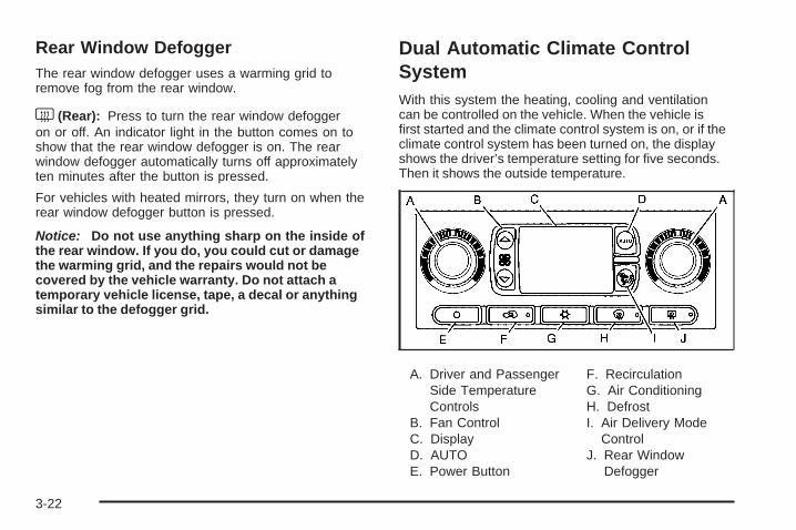
Rear Window DefoggerThe rear window defogger uses a warming grid toremove fog from the rear window.
< (Rear): Press to turn the rear window defoggeron or off. An indicator light in the button comes on toshow that the rear window defogger is on. The rearwindow defogger automatically turns off approximatelyten minutes after the button is pressed.
For vehicles with heated mirrors, they turn on when therear window defogger button is pressed.
Notice: Do not use anything sharp on the inside ofthe rear window. If you do, you could cut or damagethe warming grid, and the repairs would not becovered by the vehicle warranty. Do not attach atemporary vehicle license, tape, a decal or anythingsimilar to the defogger grid.
Dual Automatic Climate ControlSystemWith this system the heating, cooling and ventilationcan be controlled on the vehicle. When the vehicle isfirst started and the climate control system is on, or if theclimate control system has been turned on, the displayshows the driver’s temperature setting for five seconds.Then it shows the outside temperature.
A. Driver and PassengerSide TemperatureControls
B. Fan ControlC. DisplayD. AUTOE. Power Button
F. RecirculationG. Air ConditioningH. DefrostI. Air Delivery Mode
ControlJ. Rear Window
Defogger
3-22
Outside Air Temperature DisplayA new outside temperature reading is displayed ifthe vehicle has been off for more than three hours.If the vehicle has been off for less than three hours,the old temperature reading may be displayed becauseunderhood heat is affecting the true outside temperature.Underhood heat can also affect the outside temperaturewhile the engine is running. It may also take severalminutes of driving before the display updates tothe actual outside temperature.
Automatic Operation
AUTO (Automatic): When automatic operation isactive, the system controls the air delivery mode,fan speed, and temperature inside the vehicle.
Use the steps below to place the entire system inautomatic mode:
1. Press AUTO.When AUTO is selected, the air conditioning and airinlet are automatically controlled. The air conditioningcompressor will run continuously when the outsidetemperature is over approximately 40°F (4°C).The air inlet will normally be set to outside air.If it is hot outside, the air inlet automatically changesto recirculate inside air to help quickly cool downthe vehicle.
2. Set the driver’s and passenger’s temperature.To find your comfort setting, start with a 72°F (22°C)temperature setting and allow about 20 minutes forthe system to adjust. Turn the driver or passengerside temperature knob to adjust the temperaturesetting as necessary. If a temperature setting of60°F (15°C) is chosen, the system will remain at themaximum cooling setting. If a temperature setting of90°F (32°C) is chosen, the system remains at themaximum heat setting. Choosing either maximumsetting may not cause the vehicle to heat or coolany faster.
Manual Operation
9 (Off): Press to turn off the entire climate controlsystem. Outside air still enters the vehicle, and will bedirected to the floor. The system turns on by pressingeither AUTO, air delivery mode, fan control, or byadjusting either temperature knob.
Driver’s Side Temperature Knob: Turn clockwiseor counterclockwise to increase or decrease thetemperature on the driver side of the vehicle.The display will show the temperature settingdecreasing or increasing and an arrow pointingtoward the driver. This knob can also adjust thepassenger side temperature setting if the twoare linked.
3-23
Passenger Side Temperature Knob: Turn clockwiseor counterclockwise to increase or decrease thetemperature on the passenger side of the vehicle. Thedisplay will show the temperature setting decreasing orincreasing and an arrow pointing toward the passenger.The passenger temperature setting can be set to matchand link to the driver’s temperature setting by pressingand holding the AUTO button for three seconds. Whenadjusting the driver side temperature setting, thepassenger side temperature setting will follow and botharrows will appear on the display. The passenger sidetemperature setting also resets and re-links to the driverside temperature setting if the vehicle has been off formore than three hours.
w9x (Fan Control): Press the arrows to increaseor decrease the fan speed. The display shows theselected fan speed and the driver side temperaturesetting for five seconds.
C (Air Delivery Mode Control): Press to change thedirection of the airflow in the vehicle. The air deliverymodes will appear on the display as it is being adjusted.The display shows the selected air delivery mode andthe driver temperature setting for five seconds.
To change the current air delivery mode, select one ofthe following:
H (Vent): Air is directed to the instrument paneloutlets.
) (Bi-Level): Air is divided between the instrumentpanel and floor outlets. Some air is directed towardthe windshield and side window outlets. Cooler air isdirected to the upper outlets and warmer air to thefloor outlets.
6 (Floor): Air is directed to the floor outlets. Someair also comes out of the defroster and side windowoutlets. The recirculation button cannot be selectedin floor mode.
- (Defog): This mode clears the windows of fog ormoisture. Air is directed to the floor and windshieldoutlets.
0 (Front Defrost): Press the front defrost buttonto clear the windows of fog or frost more quickly. Thesystem automatically controls the fan speed if defrost isselected from AUTO mode. If the outside temperature is40°F (4°C) or warmer, the air conditioning compressorruns automatically to help dehumidify the air and dry thewindshield.
Do not drive the vehicle until all the windows are clear.
3-24
# A/C (Air Conditioning): Press to turn the airconditioning system on or off. When the system is on,the system automatically begins to cool and dehumidifythe air inside of the vehicle. The air conditioning symbolappears on the display when the air conditioning is onand turns off when the air conditioning is off.
If the air conditioning is turned off while in front defrostor defog mode, the air conditioning symbol turns off,however, the A/C compressor remains on to helpde-humidify the air inside the vehicle. If one of theother modes is selected, the compressor will thenturn the A/C off until it is selected again or the AUTObutton is pressed.
To avoid fogging the inside glass on rainy and humiddays at a temperature above freezing, press the airconditioning button to run the A/C compressor. Also it isbest to avoid the use of the recirculation mode exceptwhen maximum air conditioning performance is neededor for short times to avoid exterior odors.
You may notice a slight change in engine performancewhen the air-conditioning compressor shuts off and turnson again. This is normal.
@ (Recirculation): Press to turn the recirculationmode on or off. An indicator light comes on to showthat recirculation is on. This mode recirculates andhelps to quickly cool the air inside the vehicle. It canbe used to help prevent outside air and odors fromentering the vehicle. Recirculation mode can be usedwith vent and bi-level modes, but it cannot be usedwith floor, defog or defrost modes.
If recirculation mode is selected with floor, defog,or defrost modes, the indicator flashes three timesand turns off to indicate the selection is not available.
The air conditioning compressor may also run whilein recirculation mode. This is normal and helps toprevent window fogging.
If the weather is cold and damp, the system may causethe windows to fog while using recirculation mode.If the windows do start to fog, select defog or defrostmode and increase fan speed.
Recirculation mode, if selected, will be cleared when theengine is turned off.
3-25

Rear Window DefoggerThe rear window defogger uses a warming grid toremove fog from the rear window.
< (Rear): Press to turn the rear window defogger onor off.
An indicator light comes on to show that the rearwindow defogger is on.
The rear window defogger will turn off approximately10 minutes after the button is pressed. If additionalwarming time is needed, press the button again.
The heated mirrors will also come on when the rearwindow defogger is turned on. See Outside HeatedMirrors on page 2-44.
Notice: Do not use a razor blade or sharp object toclear the inside rear window. Do not adhere anythingto the defogger grid lines in the rear glass. Theseactions may damage the rear defogger. Repairswould not be covered by your warranty.
Outlet AdjustmentUse the air outlets located in the center and on the sideof the instrument panel to direct the airflow. Use thethumbwheels near the air outlets to open or close offthe airflow.
Operation Tips• Clear away any ice, snow, or leaves from air inlets
at the base of the windshield that could block theflow of air into the vehicle.
• Keep the path under the front seats clear of objectsto help circulate the air inside of the vehicle moreeffectively.
• Use of non-GM approved hood deflectors canadversely affect the performance of the system.Check with your dealer/retailer before addingequipment to the outside of the vehicle.
3-26
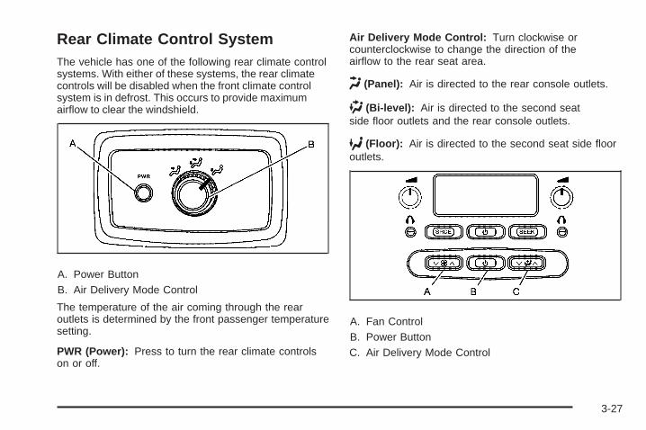
Rear Climate Control SystemThe vehicle has one of the following rear climate controlsystems. With either of these systems, the rear climatecontrols will be disabled when the front climate controlsystem is in defrost. This occurs to provide maximumairflow to clear the windshield.
A. Power ButtonB. Air Delivery Mode Control
The temperature of the air coming through the rearoutlets is determined by the front passenger temperaturesetting.
PWR (Power): Press to turn the rear climate controlson or off.
Air Delivery Mode Control: Turn clockwise orcounterclockwise to change the direction of theairflow to the rear seat area.
H (Panel): Air is directed to the rear console outlets.
) (Bi-level): Air is directed to the second seatside floor outlets and the rear console outlets.
6 (Floor): Air is directed to the second seat side flooroutlets.
A. Fan ControlB. Power ButtonC. Air Delivery Mode Control
3-27

If the vehicle has the rear seat audio system, the lowerbuttons are used to adjust the rear seat climate controlsystem. The temperature of the air coming through therear outlets is determined by the front passengertemperature setting.
P (On/Off): Press to turn the rear climate controls onor off.
z 9 y (Fan Control): Press to increase or decreasethe fan speed.
z \y (Air Delivery Mode Control): Press tochange the direction of airflow (panel, bi-level or floor)to the rear seat area.
The rear control only turns on if the front climate controlsystem is on and not in defrost mode.
Warning Lights, Gages, andIndicatorsWarning lights and gages can signal that something iswrong before it becomes serious enough to cause anexpensive repair or replacement. Paying attention tothe warning lights and gages could prevent injury.
Warning lights come on when there may be or is aproblem with one of the vehicle’s functions. Somewarning lights come on briefly when the engine isstarted to indicate they are working.
Gages can indicate when there may be or is a problemwith one of the vehicle’s functions. Often gages andwarning lights work together to indicate a problem withthe vehicle.
When one of the warning lights comes on and stays onwhile driving, or when one of the gages shows theremay be a problem, check the section that explainswhat to do. Follow this manual’s advice. Waiting todo repairs can be costly and even dangerous.
3-28

Instrument Panel ClusterYour instrument panel cluster is designed to let you know at a glance how your vehicle is running. You will knowhow fast you are going, about how much fuel you have used, and many other things you will need to know to drivesafely and economically.
United States Uplevel version shown, Canada, Base and SS Model similar
3-29
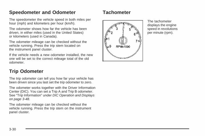
Speedometer and OdometerThe speedometer the vehicle speed in both miles perhour (mph) and kilometers per hour (km/h).
The odometer shows how far the vehicle has beendriven, in either miles (used in the United States)or kilometers (used in Canada).
The odometer mileage can be checked without thevehicle running. Press the trip stem located onthe instrument panel cluster.
If the vehicle needs a new odometer installed, the newone will be set to the correct mileage total of the oldodometer.
Trip OdometerThe trip odometer can tell you how far your vehicle hasbeen driven since you last set the trip odometer to zero.
The odometer works together with the Driver InformationCenter (DIC). You can set a Trip A and Trip B odometer.See “Trip Information” under DIC Operation and Displayson page 3-48.
The odometer mileage can be checked without thevehicle running. Press the trip stem on the instrumentpanel cluster.
Tachometer
The tachometerdisplays the enginespeed in revolutionsper minute (rpm).
3-30

Safety Belt Reminders
Safety Belt Reminder LightWhen the engine is started, a chime sounds for severalseconds to remind a driver to fasten the safety belt,unless the driver safety belt is already buckled.
The safety belt light comeson and stays on for severalseconds, then flashes forseveral more.
This chime and light are repeated if the driver remainsunbuckled and the vehicle is in motion. If the driver’ssafety belt is already buckled, neither the chime northe light comes on.
Passenger Safety Belt Reminder LightSeveral seconds after the engine is started, achime sounds for several seconds to remind the frontpassenger to buckle their safety belt. This only occursif the passenger airbag is enabled. See PassengerSensing System on page 1-63 for more information.The passenger safety belt light, located on the instrumentpanel, comes on and stays on for several seconds andthen flashes for several more.
This chime and light arerepeated if the passengerremains unbuckled andthe vehicle is in motion.
If the passenger safety belt is buckled, neither thechime nor the light comes on.
The front passenger safety belt warning light andchime may turn on if an object is put on the seat suchas a briefcase, handbag, grocery bag, laptop or otherelectronic device. To turn off the warning light and orchime, remove the object from the seat or buckle thesafety belt
3-31

Airbag Readiness LightThe system checks the airbag’s electrical system forpossible malfunctions. If the light stays on it indicatesthere is an electrical problem. The system check includesthe airbag sensor, the pretensioners, the airbag modules,the wiring and the crash sensing and diagnostic module.For more information on the airbag system, see AirbagSystem on page 1-55.
The airbag readiness lightflashes for a few secondswhen the engine is started.If the light does not comeon then, have it fixedimmediately.
{CAUTION:
If the airbag readiness light stays on after thevehicle is started or comes on while driving,it means the airbag system might not be workingproperly. The airbags in the vehicle might notinflate in a crash, or they could even inflatewithout a crash. To help avoid injury, havethe vehicle serviced right away.
If there is a problem with the airbag system, an airbagDriver Information Center (DIC) message can also comeon. See DIC Warnings and Messages on page 3-51for more information.
3-32
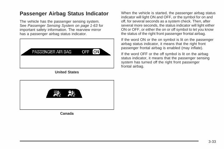
Passenger Airbag Status IndicatorThe vehicle has the passenger sensing system.See Passenger Sensing System on page 1-63 forimportant safety information. The rearview mirrorhas a passenger airbag status indicator.
When the vehicle is started, the passenger airbag statusindicator will light ON and OFF, or the symbol for on andoff, for several seconds as a system check. Then, afterseveral more seconds, the status indicator will light eitherON or OFF, or either the on or off symbol to let you knowthe status of the right front passenger frontal airbag.
If the word ON or the on symbol is lit on the passengerairbag status indicator, it means that the right frontpassenger frontal airbag is enabled (may inflate).
If the word OFF or the off symbol is lit on the airbagstatus indicator, it means that the passenger sensingsystem has turned off the right front passengerfrontal airbag.
United States
Canada
3-33
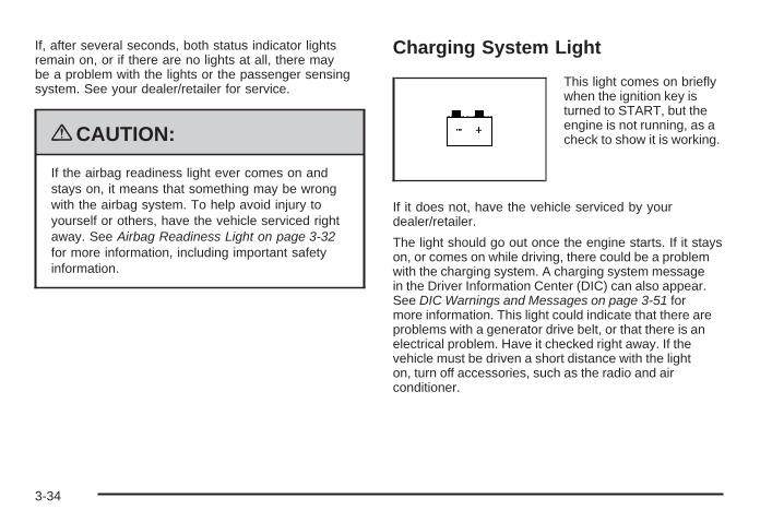
If, after several seconds, both status indicator lightsremain on, or if there are no lights at all, there maybe a problem with the lights or the passenger sensingsystem. See your dealer/retailer for service.
{CAUTION:
If the airbag readiness light ever comes on andstays on, it means that something may be wrongwith the airbag system. To help avoid injury toyourself or others, have the vehicle serviced rightaway. See Airbag Readiness Light on page 3-32for more information, including important safetyinformation.
Charging System Light
This light comes on brieflywhen the ignition key isturned to START, but theengine is not running, as acheck to show it is working.
If it does not, have the vehicle serviced by yourdealer/retailer.
The light should go out once the engine starts. If it stayson, or comes on while driving, there could be a problemwith the charging system. A charging system messagein the Driver Information Center (DIC) can also appear.See DIC Warnings and Messages on page 3-51 formore information. This light could indicate that there areproblems with a generator drive belt, or that there is anelectrical problem. Have it checked right away. If thevehicle must be driven a short distance with the lighton, turn off accessories, such as the radio and airconditioner.
3-34
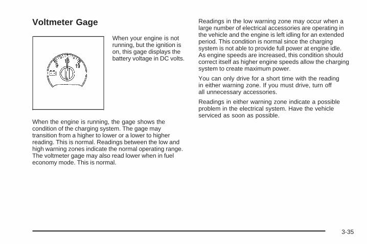
Voltmeter Gage
When your engine is notrunning, but the ignition ison, this gage displays thebattery voltage in DC volts.
When the engine is running, the gage shows thecondition of the charging system. The gage maytransition from a higher to lower or a lower to higherreading. This is normal. Readings between the low andhigh warning zones indicate the normal operating range.The voltmeter gage may also read lower when in fueleconomy mode. This is normal.
Readings in the low warning zone may occur when alarge number of electrical accessories are operating inthe vehicle and the engine is left idling for an extendedperiod. This condition is normal since the chargingsystem is not able to provide full power at engine idle.As engine speeds are increased, this condition shouldcorrect itself as higher engine speeds allow the chargingsystem to create maximum power.
You can only drive for a short time with the readingin either warning zone. If you must drive, turn offall unnecessary accessories.
Readings in either warning zone indicate a possibleproblem in the electrical system. Have the vehicleserviced as soon as possible.
3-35

Brake System Warning LightWhen the ignition is on, the brake system warning lightwill come on when you set your parking brake. The lightwill stay on if your parking brake does not release fully.If it stays on after your parking brake is fully released, itmeans your vehicle has a brake problem. A chime mayalso sound when the light comes on.
Your vehicle’s hydraulic brake system is divided intotwo parts. If one part is not working, the other partcan still work and stop you. For good braking, though,you need both parts working well.
If the warning light comes on, there could be a brakeproblem. Have your brake system inspected right away.
This light should come on briefly when you turn theignition key to ON/RUN. If it does not come on then,have it fixed so it will be ready to warn you if thereis a problem.
If the light comes on while you are driving, pull off theroad and stop carefully. You may notice that the pedalis harder to push or the pedal may go closer to thefloor. It may take longer to stop. If the light is still on,have the vehicle towed for service. See TowingYour Vehicle on page 4-40.
{CAUTION:
The brake system might not be working properly ifthe brake system warning light is on. Driving withthe brake system warning light on can lead to acrash. If the light is still on after the vehicle hasbeen pulled off the road and carefully stopped,have the vehicle towed for service.
United States Canada
3-36

Antilock Brake System (ABS)Warning Light
For vehicles withthe Antilock BrakeSystem (ABS), this lightcomes on briefly whenthe engine is started.
If it does not, have the vehicle serviced by yourdealer/retailer. If the system is working normallythe indicator light then goes off.
If the ABS light stays on, turn the ignition off. If thelight comes on while driving, stop as soon as it is safelypossible and turn the ignition off. Then start the engineagain to reset the system. If the ABS light stays on, orcomes on again while driving, the vehicle needs service.If the regular brake system warning light is not on, thevehicle still has brakes, but not antilock brakes. If theregular brake system warning light is also on, the vehicle
does not have antilock brakes and there is a problem withthe regular brakes. See Brake System Warning Light onpage 3-36.
For vehicles with a Driver Information Center (DIC),see DIC Warnings and Messages on page 3-51 forall brake related DIC messages.
StabiliTrak® Service Light
This light will come onbriefly when the engineis started.
This light will come on if a problem is detected in theStabiliTrak® system.
For more information see StabiliTrak® System onpage 4-6.
3-37
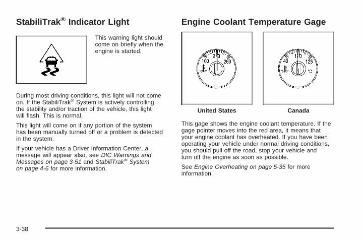
StabiliTrak® Indicator Light
This warning light shouldcome on briefly when theengine is started.
During most driving conditions, this light will not comeon. If the StabiliTrak® System is actively controllingthe stability and/or traction of the vehicle, this lightwill flash. This is normal.
This light will come on if any portion of the systemhas been manually turned off or a problem is detectedin the system.
If your vehicle has a Driver Information Center, amessage will appear also, see DIC Warnings andMessages on page 3-51 and StabiliTrak® Systemon page 4-6 for more information.
Engine Coolant Temperature Gage
This gage shows the engine coolant temperature. If thegage pointer moves into the red area, it means thatyour engine coolant has overheated. If you have beenoperating your vehicle under normal driving conditions,you should pull off the road, stop your vehicle andturn off the engine as soon as possible.
See Engine Overheating on page 5-35 for moreinformation.
United States Canada
3-38

Tire Pressure Light
For vehicles with a tirepressure light, this lightcomes on briefly whenthe engine is started andprovides information abouttire pressures and theTire Pressure MonitoringSystem.
When the Light is On SteadyThis indicates that one or more of the tires is significantlyunderinflated.
A tire pressure message in the Driver InformationCenter (DIC), can accompany the light. See DICWarnings and Messages on page 3-51 for moreinformation. Stop and check the tires as soon as it issafe to do so. If a tire is underinflated, inflate to theproper pressure. See Tires on page 5-58 for moreinformation.
When the Light Flashes First and Then isOn SteadyThis indicates that there could be a problem with theTire Pressure Monitor System. The light flashes for abouta minute and stays on steady for the remainder of theignition cycle. This sequence repeats with every ignitioncycle. See Tire Pressure Monitor System on page 5-67for more information.
Malfunction Indicator Lamp
Check Engine LightA computer system called OBD II (On-BoardDiagnostics-Second Generation) monitors operationof the fuel, ignition, and emission control systems.It ensures that emissions are at acceptable levelsfor the life of the vehicle, helping to produce a cleanerenvironment.
This light should come onwhen the ignition is on, butthe engine is not running,as a check to show itworking. If it does not,have the vehicle servicedby your dealer/retailer.
3-39
If the check engine light comes on and stays on, whilethe engine is running, this indicates that there is anOBD II problem and service is required.
Malfunctions often are indicated by the system beforeany problem is apparent. Being aware of the lightcan prevent more serious damage to the vehicle.This system assists the service technician in correctlydiagnosing any malfunction.
Notice: If the vehicle is continually driven withthis light on, after a while, the emission controlsmight not work as well, the vehicle’s fuel economymight not be as good, and the engine might notrun as smoothly. This could lead to costly repairsthat might not be covered by the vehicle warranty.
Notice: Modifications made to the engine,transmission, exhaust, intake, or fuel systemof the vehicle or the replacement of the originaltires with other than those of the same TirePerformance Criteria (TPC) can affect the vehicle’semission controls and can cause this light to comeon. Modifications to these systems could lead tocostly repairs not covered by the vehicle warranty.This could also result in a failure to pass a requiredEmission Inspection/Maintenance test. SeeAccessories and Modifications on page 5-3.
This light comes on during a malfunction in one oftwo ways:
Light Flashing: A misfire condition has been detected.A misfire increases vehicle emissions and could damagethe emission control system on the vehicle. Diagnosisand service might be required.
To prevent more serious damage to the vehicle:
• Reduce vehicle speed.
• Avoid hard accelerations.
• Avoid steep uphill grades.
• If towing a trailer, reduce the amount of cargo beinghauled as soon as it is possible.
If the light continues to flash, when it is safe to do so,stop the vehicle. Find a safe place to park the vehicle.Turn the key off, wait at least 10 seconds, and restartthe engine. If the light is still flashing, follow the previoussteps and see your dealer/retailer for service as soonas possible.
3-40
Light On Steady: An emission control systemmalfunction has been detected on the vehicle.Diagnosis and service might be required.
An emission system malfunction might be corrected bydoing the following:
• Make sure the fuel cap is fully installed. SeeFilling the Tank on page 5-8. The diagnostic systemcan determine if the fuel cap has been left off orimproperly installed. A loose or missing fuel capallows fuel to evaporate into the atmosphere.A few driving trips with the cap properly installedshould turn the light off.
• If the vehicle has been driven through a deep puddleof water, the vehicle’s electrical system might be wet.The condition is usually corrected when the electricalsystem dries out. A few driving trips should turn thelight off.
• Make sure to fuel the vehicle with quality fuel.Poor fuel quality causes the engine not to run asefficiently as designed and can cause: stalling afterstart-up, stalling when the vehicle is changed intogear, misfiring, hesitation on acceleration, orstumbling on acceleration. These conditions mightgo away once the engine is warmed up.
If one or more of these conditions occurs, change thefuel brand used. It will require at least one full tank ofthe proper fuel to turn the light off.See Gasoline Octane on page 5-6.
If none of the above have made the light turn off, yourdealer/retailer can check the vehicle. The dealer/retailerhas the proper test equipment and diagnostic tools tofix any mechanical or electrical problems that mighthave developed.
3-41
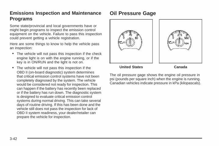
Emissions Inspection and MaintenanceProgramsSome state/provincial and local governments have ormight begin programs to inspect the emission controlequipment on the vehicle. Failure to pass this inspectioncould prevent getting a vehicle registration.
Here are some things to know to help the vehicle passan inspection:
• The vehicle will not pass this inspection if the checkengine light is on with the engine running, or if thekey is in ON/RUN and the light is not on.
• The vehicle will not pass this inspection if theOBD II (on-board diagnostic) system determinesthat critical emission control systems have not beencompletely diagnosed by the system. The vehiclewould be considered not ready for inspection. Thiscan happen if the battery has recently been replacedor if the battery has run down. The diagnostic systemis designed to evaluate critical emission controlsystems during normal driving. This can take severaldays of routine driving. If this has been done and thevehicle still does not pass the inspection for lack ofOBD II system readiness, your dealer/retailer canprepare the vehicle for inspection.
Oil Pressure Gage
The oil pressure gage shows the engine oil pressure inpsi (pounds per square inch) when the engine is running.Canadian vehicles indicate pressure in kPa (kilopascals).
United States Canada
3-42
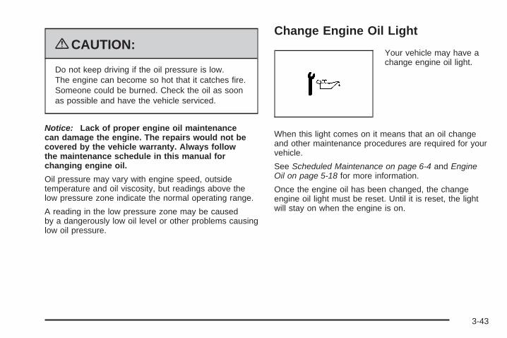
{CAUTION:
Do not keep driving if the oil pressure is low.The engine can become so hot that it catches fire.Someone could be burned. Check the oil as soonas possible and have the vehicle serviced.
Notice: Lack of proper engine oil maintenancecan damage the engine. The repairs would not becovered by the vehicle warranty. Always followthe maintenance schedule in this manual forchanging engine oil.
Oil pressure may vary with engine speed, outsidetemperature and oil viscosity, but readings above thelow pressure zone indicate the normal operating range.
A reading in the low pressure zone may be causedby a dangerously low oil level or other problems causinglow oil pressure.
Change Engine Oil Light
Your vehicle may have achange engine oil light.
When this light comes on it means that an oil changeand other maintenance procedures are required for yourvehicle.
See Scheduled Maintenance on page 6-4 and EngineOil on page 5-18 for more information.
Once the engine oil has been changed, the changeengine oil light must be reset. Until it is reset, the lightwill stay on when the engine is on.
3-43

Security Light
For information regardingthis light and the vehicle’ssecurity system, seeContent Theft-Deterrenton page 2-17.
Cruise Control Light
If your vehicle has a DriverInformation Center (DIC),this light will come on whenthe cruise control is set.
See Cruise Control on page 3-10 and DIC Warningsand Messages on page 3-51 for more information.
Reduced Engine Power Light
This light comes on whena noticeable reduction inthe vehicle’s performanceoccurs.
The vehicle can be driven at a reduced speed whenthe reduced engine power light is on, but accelerationand speed may be reduced. The performance maybe reduced until the next time you drive your vehicle.If this light stays on, see your dealer as soon as possiblefor diagnosis and repair.
This light may also come on if there is a problem withthe Electronic Throttle Control (ETC) system. If thishappens, take the vehicle in for service as soonas possible.
3-44

Highbeam On Light
This light comes on whenthe high-beam headlampsare in use.
See Headlamp High/Low-Beam Changer on page 3-8for more information.
Service Four-Wheel Drive WarningLight
This light should come onbriefly when you turn onthe ignition, as a check toshow you it is working.
The service four-wheel drive light comes on, exceptfor the SS model, to indicate that there may be aproblem with the drive system and service is required.Malfunctions can be indicated by the system before anyproblem is apparent, which may prevent serious damageto the vehicle. This system is also designed to assist yourGM dealer in correctly diagnosing a malfunction.
Check Gages Warning Light
The check gages light willcome on briefly when youare starting the engine.
If the light comes on and stays on while you aredriving, check your coolant temperature and engineoil pressure gages to see if they are in the warningzones.
3-45

Gate Ajar Light
If this light comes on, theliftgate or liftglass is notcompletely shut.
Close the liftgate or liftglass. Never drive with the liftgateor liftglass even partially open.
Fuel Gage
When the ignition is on, the fuel gage tells you abouthow much fuel you have remaining.
An arrow on the fuel gage indicates the side of thevehicle the fuel door is on.
Here are four things that some owners ask about.None of these show a problem with your fuel gage:
• At the gas station, the gas pump shuts off before thegage reads full.
• It takes a little more or less fuel to fill up than thegage indicated. For example, the gage may haveindicated the tank was half full, but it actually tooka little more or less than half the tank’s capacityto fill the tank.
• The gage moves a little when you turn a corner orspeed up.
• The gage doesn’t go back to empty when you turnoff the ignition.
United States Canada
3-46
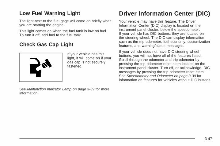
Low Fuel Warning LightThe light next to the fuel gage will come on briefly whenyou are starting the engine.
This light comes on when the fuel tank is low on fuel.To turn it off, add fuel to the fuel tank.
Check Gas Cap Light
If your vehicle has thislight, it will come on if yourgas cap is not securelyfastened.
See Malfunction Indicator Lamp on page 3-39 for moreinformation.
Driver Information Center (DIC)Your vehicle may have this feature. The DriverInformation Center (DIC) display is located on theinstrument panel cluster, below the speedometer.If your vehicle has DIC buttons, they are located onthe steering wheel. The DIC can display informationsuch as the trip odometer, fuel economy, customizationfeatures, and warning/status messages.
If your vehicle does not have DIC steering wheelbuttons, you will not have all of the features listed.Scroll through the odometer and trip odometer bypressing the trip odometer reset stem located on theinstrument panel cluster. Turn off, or acknowledge, DICmessages by pressing the trip odometer reset stem.See Speedometer and Odometer on page 3-30 forinformation on features for vehicles without DIC buttons.
3-47
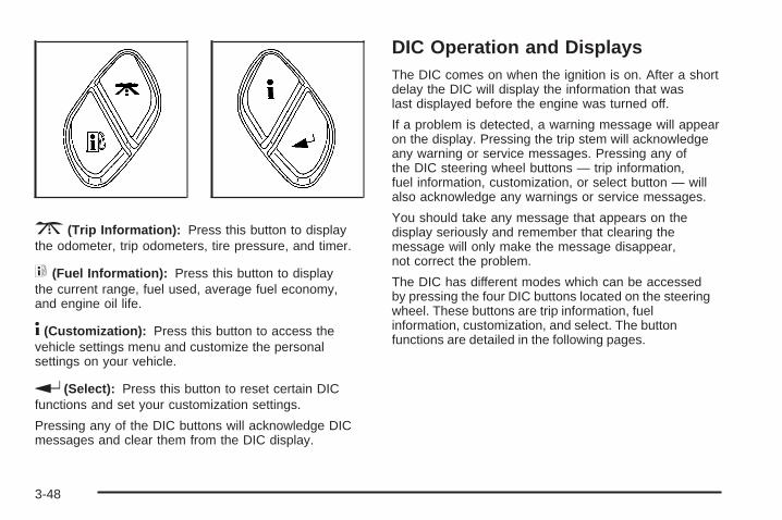
3 (Trip Information): Press this button to displaythe odometer, trip odometers, tire pressure, and timer.
t (Fuel Information): Press this button to displaythe current range, fuel used, average fuel economy,and engine oil life.
4 (Customization): Press this button to access thevehicle settings menu and customize the personalsettings on your vehicle.
r (Select): Press this button to reset certain DICfunctions and set your customization settings.
Pressing any of the DIC buttons will acknowledge DICmessages and clear them from the DIC display.
DIC Operation and DisplaysThe DIC comes on when the ignition is on. After a shortdelay the DIC will display the information that waslast displayed before the engine was turned off.
If a problem is detected, a warning message will appearon the display. Pressing the trip stem will acknowledgeany warning or service messages. Pressing any ofthe DIC steering wheel buttons — trip information,fuel information, customization, or select button — willalso acknowledge any warnings or service messages.
You should take any message that appears on thedisplay seriously and remember that clearing themessage will only make the message disappear,not correct the problem.
The DIC has different modes which can be accessedby pressing the four DIC buttons located on the steeringwheel. These buttons are trip information, fuelinformation, customization, and select. The buttonfunctions are detailed in the following pages.
3-48
Trip Information Button
3 (Trip Information): Press the trip informationbutton to scroll through the ODOMETER, TRIP A,TRIP B, TIRE PRESSURES, and TIMER.
Odometer: Press the trip information button untilODOMETER appears on the display. This mode showsthe total distance the vehicle has been driven in eithermiles or kilometers. Pressing the reset stem located onthe instrument cluster with the vehicle off will also displaythe odometer.
Trip A: Press the trip information button until TRIP Aappears on the display. This mode shows the currentdistance traveled since the last reset for TRIP A in eithermiles or kilometers.
Trip B: Press the trip information button until TRIP Bappears on the display. This mode shows the currentdistance traveled since the last reset for TRIP B in eithermiles or kilometers.
To reset TRIP A or TRIP B information, press and holdthe select button for one second while in one of the tripmodes. This will reset the information for TRIP A orTRIP B.
You can also reset the TRIP A or TRIP B while they aredisplayed by pressing the reset stem on the cluster. If youpress and hold the reset stem or the select button formore than four seconds, the display will show thedistance traveled since the last ignition cycle forTRIP A or TRIP B.
Tire Pressures: On vehicles with the Tire PressureMonitor System (TPMS), press the trip informationbutton until TIRE PRESSURES appears on the display.This mode shows the tire pressure in pounds persquare inch (psi) or kilopascals (kPa). Press the selectbutton to scroll through the following information:
• LF TIRE shows the tire pressure for the frontdriver’s side tire.
• RF TIRE shows the tire pressure for the frontpassenger’s side tire.
• LR TIRE shows the tire pressure for the reardriver’s side tire.
• RR TIRE shows the tire pressure for the rearpassenger’s side tire.
Timer: The DIC can be used as a timer. Press theselect button while TIMER is displayed to start the timer.The display will show the amount of time that haspassed since the timer was last reset, not including timethe ignition is off. Time will continue to be counted aslong as the ignition is on, even if another display is beingshown on the DIC. The timer will record up to 99 hours,59 minutes and 59 seconds (99:59:59) after whichthe display will roll back to zero.
To stop the counting of time, press the select buttonbriefly while TIMER is displayed.
To reset the timer to zero, press and hold the selectbutton while TIMER is displayed.
3-49

Fuel Information Button
t (Fuel Information): Press the fuel informationbutton to scroll through the range, fuel used, averagefuel economy, and the engine oil life system.
Fuel Range: Press the fuel information button untilRANGE appears on the display. This mode shows theremaining distance you can drive without refueling.It is based on fuel economy and the fuel remaining inthe fuel tank. The display will show LOW if the fuel levelis low.
The fuel economy data used to determine fuel range isan average of recent driving conditions. As yourdriving conditions change, this data is gradually updated.Fuel range cannot be reset.
Fuel Used: Press the fuel information button untilFUEL USED appears on the display. This mode showsthe number of gallons or liters of fuel used since thelast reset of this menu item. To reset the fuel usedinformation, press and hold the select button for onesecond while FUEL USED is displayed.
Average Fuel Economy: Press the fuel informationbutton until AVG. ECON appears on the display.This mode shows how many miles per gallon (MPG),liters per 100 kilometers (L/100 km), or kilometersper liter (km/L) your vehicle is getting based on currentand past driving conditions.
Press and hold the select button for one second whileAVG. ECON is displayed to reset the average fueleconomy. Average fuel economy will then be calculatedstarting from that point. If the average fuel economyis not reset, it will be continually updated each time youdrive.
Engine Oil Life System: Press the fuel informationbutton until ENGINE OIL LIFE appears on the display.The engine oil life system shows an estimate of theoil’s remaining useful life. It will show 100% when thesystem is reset after an oil change. It will alert youto change the oil on a schedule consistent with yourdriving conditions.
Always reset the engine oil life system after an oilchange. To reset the engine oil life system, see EngineOil Life System on page 5-22.
In addition to the engine oil life system monitoring theoil life, additional maintenance is recommended inthe Maintenance Schedule in this manual. See EngineOil on page 5-18 and Scheduled Maintenance onpage 6-4.
3-50
Customization Button
4 (Customization): Press the customization button toaccess the VEHICLE SETTINGS menu and customizethe settings to your vehicle. See DIC VehicleCustomization on page 3-56 for more information.
Select Button
r (Select): Press the select button to reset certainDIC functions, turn off or acknowledge messages onthe DIC display, and set your customization settings.For example, this button will allow you to reset the tripodometers, turn off the FUEL LEVEL LOW message,and enables you to scroll through and select thelanguage in which the DIC information will appear.
DIC Warnings and MessagesMessages are displayed on the DIC to notify the driverthat the status of the vehicle has changed and thatsome action may be needed to correct the condition.Multiple messages may appear one after another.
Some messages may not require immediate action.Press any of the DIC buttons on the steering wheel orthe trip odometer reset stem on the instrument panelcluster to acknowledge that you received the messagesand to clear them from the display.
Some messages cannot be cleared from the displaybecause they are more urgent. These messages requireaction before they can be removed from the DIC display.Take any messages that appear on the display seriouslyand remember that clearing the messages will only makethe messages disappear, not correct the problem.
The following are the possible messages that can bedisplayed and some information about them.
CHANGE ENGINE OILThis message displays when the engine oil needs tobe changed and service is required for your vehicle. SeeScheduled Maintenance on page 6-4 and Engine Oil onpage 5-18 for more information. Also see Engine Oil LifeSystem on page 5-22 for information on how to reset themessage. This message clears itself after 10 secondsuntil the next ignition cycle.
3-51

CHECK TIRE PRESSUREOn vehicles with the Tire Pressure Monitor System(TPMS), this message displays when the pressure inone or more of the vehicle’s tires needs to be checked.If a tire pressure message appears on the DIC, stop assoon as you can. Have the tire pressures checked andset to those shown on the Tire Loading Informationlabel. See Tires on page 5-58, Loading the Vehicle onpage 4-33, and Inflation - Tire Pressure on page 5-65.The DIC also shows the tire pressure values. See DICOperation and Displays on page 3-48. If the tire pressureis low, the low tire pressure warning light comes on.See Tire Pressure Light on page 3-39.
CHECK WASHER FLUIDThis message displays if the washer fluid level is low.Adding washer fluid to the windshield washer fluidreservoir clears this message. See Windshield WasherFluid on page 5-38. This message clears itself after10 seconds, or you can manually clear it from theDIC display.
DRIVER DOOR AJARThis message displays and a chime sounds if the driverdoor is not fully closed. Stop and turn off the vehicle,check the door for obstructions, and close the dooragain. Check to see if the message still appears onthe DIC.
ENGINE COOLANT HOT/ENGINEOVERHEATED
Notice: If you drive your vehicle while the engineis overheating, severe engine damage may occur.If an overheat warning appears on the instrumentpanel cluster and/or DIC, stop the vehicle as soon aspossible. Do not increase the engine speed abovenormal idling speed. See Engine Overheatingon page 5-35 for more information.
This message displays and a chime sounds if thecooling system temperature gets hot. See EngineOverheating on page 5-35 for the proper courseof action. This message clears when the coolanttemperature drops to a safe operating temperature.
3-52

FUEL LEVEL LOWThis message displays and a chime sounds if the fuellevel is low. Refuel as soon as possible. See LowFuel Warning Light on page 3-47, Filling the Tank onpage 5-8, and Fuel on page 5-5 for more information.
ICE POSSIBLEThis message may display if the outside temperaturereaches a level where ice could form on the roadway.Adjust your driving accordingly. If the temperaturerises to a safe level, the message clears. This messageclears itself after 10 seconds, or you can manuallyclear it from the DIC display.
KEY FOB # BATTERY LOWThis message displays if a Remote Keyless Entry (RKE)transmitter battery is low. Replace the battery in thetransmitter. See “Battery Replacement” under RemoteKeyless Entry (RKE) System Operation on page 2-5.
LEFT REAR DOOR AJARThis message displays and a chime sounds if the driverside rear door is not fully closed. Stop and turn off thevehicle, check the door for obstructions, and close thedoor again. Check to see if the message still appears onthe DIC.
OIL PRESSURE LOW/STOP ENGINE
Notice: If you drive your vehicle while the engineoil pressure is low, severe engine damage may occur.If a low oil pressure warning appears on the DriverInformation Center (DIC), stop the vehicle as soon aspossible. Do not drive the vehicle until the cause ofthe low oil pressure is corrected. See Engine Oil onpage 5-18 for more information.
This message displays if low oil pressure levels occur.Stop the vehicle as soon as safely possible and donot operate it until the cause of the low oil pressurehas been corrected. Check the oil as soon as possibleand have your vehicle serviced by your dealer/retailer.See Engine Oil on page 5-18.
PASSENGER DOOR AJARThis message displays and a chime sounds if thepassenger door is not fully closed. Stop and turn offthe vehicle, check the door for obstructions, and closethe door again. Check to see if the message stillappears on the DIC.
REAR ACCESS OPENThis message displays and a chime sounds if the liftgateor liftglass is open while the ignition is in ON/RUN.Turn off the vehicle and check the liftgate and liftglass.See Liftgate/Liftglass on page 2-13. Restart the vehicleand check for the message on the DIC display.
3-53

RIGHT REAR DOOR AJARThis message displays and a chime sounds if thepassenger side rear door is not fully closed. Stop andturn off the vehicle, check the door for obstructions,and close the door again. Check to see if the messagestill appears on the DIC.
SERVICE AIR BAGThis message displays if there is a problem with theairbag system. Have your dealer/retailer inspect thesystem for problems. See Airbag Readiness Light onpage 3-32 and Airbag System on page 1-55 for moreinformation.
SERVICE BRAKE SYSTEMThis message displays if a problem occurs with thebrake system. If this message appears, stop as soonas possible and turn off the vehicle. Restart the vehicleand check for the message on the DIC display. If themessage is still displayed, or appears again when youbegin driving, the brake system needs service. See yourdealer/retailer.
SERVICE CHARGING SYS (System)This message displays if there is a problem with thebattery charging system. Under certain conditions, thecharging system light may also turn on in the instrumentpanel cluster. See Charging System Light on page 3-34.The battery will not be charging at an optimal rate andthe vehicle will lose the ability to enter the fuel economymode. The vehicle is safe to drive, however youshould have the electrical system checked byyour dealer/retailer.
SERVICE STABILITRAKIf this message displays, it means there may be aproblem with the StabiliTrak system. If this messageappears, try to reset the system by performing thefollowing: stop; turn off the engine; then start the engineagain. If this message still comes on, it means there is aproblem. You should see your dealer/retailer for service.The vehicle is safe to drive, however, you do not have thebenefit of StabiliTrak, so reduce your speed and driveaccordingly.
3-54
SERVICE TIRE MONITOROn vehicles with the Tire Pressure MonitorSystem (TPMS), this message displays if a parton the TPMS is not working properly. The tire pressurelight also flashes and then remains on during the sameignition cycle. See Tire Pressure Light on page 3-39.Several conditions may cause this message to appear.See Tire Pressure Monitor Operation on page 5-69 formore information. If the warning comes on and stayson, there may be a problem with the TPMS. See yourdealer/retailer.
STABILITRAK ACTIVEThis message displays anytime the StabiliTrak systemactivates to maintain vehicle stability. Any combinationof engine speed management, brake traction control,and stability control displays this message.
STABILITRAK NOT READYThis message may display if driving conditions delayStabiliTrak system initialization. This is normal. Oncethe system initializes, this message will no longerbe displayed on the DIC.
STABILITRAK OFFThis message displays when you press the StabiliTrakbutton for more than five seconds or when stabilitycontrol has been automatically disabled. The StabiliTrakbutton is located on the transmission shift handle.To limit wheel spin and realize the full benefits of thestability enhancement system, you should normally leaveStabiliTrak on. However, you should turn StabiliTrak offif your vehicle gets stuck in sand, mud, ice, or snow andyou want to rock your vehicle to attempt to free it, or if youare driving in extreme off-road conditions and requiremore wheel spin. See If Your Vehicle is Stuck in Sand,Mud, Ice, or Snow on page 4-32. To turn the StabiliTraksystem back on, press the StabiliTrak button again.
There are several conditions that can cause thismessage to appear.
• The message may display if the brake systemwarning light is on. See Brake System WarningLight on page 3-36.
• The message displays if the vehicle is shiftedinto 4LO.
The message turns off as soon as the conditions thatcaused the message to be displayed are no longerpresent.
3-55
TIGHTEN FUEL CAPThis message may display and a chime may soundif the vehicle’s fuel cap is not tightened properly. Fullyreinstall the fuel cap. See Filling the Tank on page 5-8.The diagnostic system can determine if the fuel cap hasbeen left off or improperly installed. A loose or missingfuel cap allows fuel to evaporate into the atmosphere.This message remains on until it is manually cleared fromthe DIC display. The DIC message is also cancelled if theignition is turned off.
The DIC message and the Service Engine Soon lightmay come on again during a second trip if the fuel capis still not tightened properly. See Malfunction IndicatorLamp on page 3-39 for more information.
TRACTION CONTROL OFFThis message displays when you momentarily pressthe StabiliTrak button located on the transmissionshift handle. In this mode, stability control and thebrake-traction control are functional. Engine speedmanagement will be modified and the driven wheelscan spin more freely. For more details on this mode,see StabiliTrak® System on page 4-6.
TURN SIGNAL ONThis message displays and a chime sounds if a turnsignal is left on for 3/4 of a mile (1.2 km). Move the turnsignal/multifunction lever to the off position.
DIC Vehicle CustomizationYour vehicle may have customization capabilities thatallow you to program some features to one settingbased on your preference. All of the customizableoptions listed may not be available on your vehicle.Only the options available display on the DriverInformation Center (DIC).
The default settings for the customization features wereset when your vehicle left the factory, but may havebeen changed from their default state since then.
To change feature preferences, make sure the ignitionis on and the vehicle is in P (Park). To avoid excessivedrain on the battery, it is recommended that theheadlamps are turned off.
Press 4 to scroll through the available customizableoptions.
After pressing 4 , VEHICLE SETTINGS momentarilydisplays before going to a customization option.
3-56
Lock Doors
Press 4 until LOCK DOORS: IN GEAR appears in thedisplay. To select your preference for automatic locking,press r while LOCK DOORS: IN GEAR is displayedon the DIC. Pressing r will scroll through thefollowing settings:
LOCK DOORS: IN GEAR (default): The doors will lockwhen the vehicle is shifted out of P (Park).
LOCK DOORS: WITH SPEED: The doors will lockwhen the vehicle speed is above 8 mph (13 km/h) forthree seconds.
To select a setting and move on to the next feature,press 4 while the desired setting is displayed on the DIC.
See Programmable Automatic Door Locks on page 2-9for more information.
Unlock Doors
Press 4 until UNLOCK DOORS: IN PARK appearsin the display. To select your preference for automaticunlocking, press r while UNLOCK DOORS: IN PARKis displayed on the DIC. Pressing r will scroll throughthe following settings:
UNLOCK DOORS: IN PARK (default): All of the doorswill unlock when the vehicle is shifted into P (Park).
UNLOCK DRIVER: IN PARK: The driver’s door will beunlocked when the vehicle is shifted into P (Park).
UNLOCK DOORS: KEY OUT: All of the doorswill unlock when the key is taken out of the ignition.
UNLOCK DOORS: MANUALLY: The doors will not beunlocked automatically.
To select a setting and move on to the next feature,press 4 while the desired setting is displayed on the DIC.
See Programmable Automatic Door Locks on page 2-9for more information.
3-57
Lock Feedback
Press 4 until LOCK FEEDBACK: BOTH appears inthe display. To select your preference for the feedbackyou receive when locking the vehicle with the RemoteKeyless Entry (RKE) transmitter, press r whileLOCK FEEDBACK: BOTH is displayed on the DIC.Pressing r will scroll through the following settings:
LOCK FEEDBACK: BOTH (default): The parkinglamps will flash each time you press the button withthe lock symbol on the RKE transmitter and the hornwill chirp the second time you press the lock button.
LOCK FEEDBACK: OFF: There will be no feedbackwhen locking the vehicle.
LOCK FEEDBACK: LAMPS: The parking lamps willflash each time you press the button with the locksymbol on the RKE transmitter.
LOCK FEEDBACK: HORN: The horn will chirp thesecond time you press the button with the lock symbolon the RKE transmitter.
To select a setting and move on to the next feature,press 4 while the desired setting is displayed on the DIC.
Unlock Feedback
Press 4 until UNLOCK FEEDBACK: LAMPS appearsin the display. To select your preference for thefeedback you will receive when unlocking the vehiclewith the Remote Keyless Entry (RKE) transmitter,press r while UNLOCK FEEDBACK: LAMPS isdisplayed on the DIC. Pressing r will scroll throughthe following settings:
UNLOCK FEEDBACK: LAMPS (default): The parkinglamps will flash each time you press the button withthe unlock symbol on the RKE transmitter.
UNLOCK FEEDBACK: HORN: The horn will chirpthe second time you press the button with the unlocksymbol on the RKE transmitter.
UNLOCK FEEDBACK: BOTH: The parking lampswill flash each time you press the button with the unlocksymbol on the RKE transmitter and the horn will chirp thesecond time you press the unlock button.
UNLOCK FEEDBACK: OFF: There will be no feedbackwhen unlocking the vehicle.
To select a setting and move on to the next feature,press 4 while the desired setting is displayed on the DIC.
3-58
Headlamp Delay
Press 4 until HEADLAMP DELAY: 10 SEC appearsin the display. To select your preference for how longthe headlamps will stay on after you turn off the vehicle,press r while HEADLAMP DELAY: 10 SEC isdisplayed on the DIC. Pressing r will scroll throughthe following settings:
HEADLAMP DELAY: 10 SEC (Seconds) (default):The headlamps will stay on for 10 seconds.
HEADLAMP DELAY: 20 SEC: The headlamps will stayon for 20 seconds.
HEADLAMP DELAY: 40 SEC: The headlamps will stayon for 40 seconds.
HEADLAMP DELAY: 1 MIN (Minute): The headlampswill stay on for 1 minute.
HEADLAMP DELAY: 2 MIN: The headlamps will stayon for 2 minutes.
HEADLAMP DELAY: 3 MIN: The headlamps will stayon for 3 minutes.
HEADLAMP DELAY: OFF: The headlamps will notturn on.
To select a setting and move on to the next feature,press 4 while the desired setting is displayed on the DIC.
Perimeter Lights
Press 4 until PERIMETER LIGHTS: ON appears in thedisplay. To select your preference for perimeter lighting,press r while PERIMETER LIGHTS: ON is displayedon the DIC. Pressing r will scroll through the followingsettings:
PERIMETER LIGHTS: ON (default): The headlampsand back-up lamps will come on for 40 seconds, ifit is dark enough outside, when you unlock the vehiclewith the Remote Keyless Entry (RKE) transmitter.
PERIMETER LIGHTS: OFF: The perimeter lights willnot come on when you unlock the vehicle with the RKEtransmitter.
To select a setting and move on to the next feature,press 4 while the desired setting is displayed on the DIC.
3-59
Easy Exit Seat
Press 4 until EASY EXIT SEAT: OFF appears in thedisplay. To select your preference for seat position exit,press r while EASY EXIT SEAT: OFF is displayedon the DIC. Pressing r will scroll through thefollowing settings:
EASY EXIT SEAT: OFF (default): No seat exit recallwill occur.
EASY EXIT SEAT: ON: The driver’s seat will move tothe exit position when the key is removed from theignition.
To select a setting and move on to the next feature,press 4 while the desired setting is displayed on the DIC.
See “Easy Exit Seat” under Memory Seat on page 1-5for more information.
Seat Recall
Press 4 until SEAT RECALL: OFF appears in thedisplay. To select your preference for recall of the driver’smemory seat and adjustable pedals, if your vehicle hasthis feature, press r while SEAT RECALL: OFF isdisplayed on the DIC. Pressing r will scroll throughthe following settings:
SEAT RECALL: OFF (default): The driver’s memoryseat and adjustable pedals position you saved will onlybe recalled when the memory button 1 or 2 is pressed.
SEAT RECALL: AT KEY IN: The driver’s memory seatand adjustable pedals position you saved will be recalledwhen you put the key in the ignition.
SEAT RECALL: ON REMOTE: The driver’s memoryseat and adjustable pedals position you saved willbe recalled when you unlock the vehicle with theRemote Keyless Entry (RKE) transmitter. Whicheverposition, 1 or 2, you programmed with the transmitterbeing used to unlock the vehicle is the one that willbe recalled.
To select a setting and move on to the next feature,press 4 while the desired setting is displayed on the DIC.
See “Easy Exit Seat” under Memory Seat on page 1-5for more information.
3-60
Alarm Warning
Press 4 until ALARM WARNING: BOTH appears inthe display. To select your preference for alarm warning,press r while ALARM WARNING: BOTH is displayedon the DIC. Pressing r will scroll through the followingsettings:
ALARM WARNING: BOTH (default): The headlampswill flash and the horn will chirp when the alarm isactive.
ALARM WARNING: HORN: The horn will chirp whenthe alarm is active.
ALARM WARNING: LAMPS: The headlamps will flashwhen the alarm is active.
ALARM WARNING: OFF: There will be no alarmwarning on activation.
To select a setting and move on to the next feature,press 4 while the desired setting is displayed on the DIC.
See Content Theft-Deterrent on page 2-17 for moreinformation.
Language
Press 4 until LANGUAGE: ENGLISH appears in thedisplay. To select your preference for display language,press r while LANGUAGE: ENGLISH is displayedon the DIC. Pressing r will scroll through thefollowing settings:
ENGLISH (default): All messages will appearin English.
FRANCAIS: All messages will appear in French.
ESPANOL: All messages will appear in Spanish.
To select a setting and move on to the next feature,press 4 while the desired setting is displayed on the DIC.
If you accidentally choose a language that you donot want or understand, press and hold 4 and the tripinformation button at the same time. The DIC will beginscrolling through the languages in their particularlanguage. English will be in English, Francais will be inFrench, and Espanol will be in Spanish. When you seethe language that you would like, release both buttons.The DIC will then display the information in the languageyou chose.
You can also scroll through the different languages bypressing and holding the trip reset stem for four seconds,as long as you are in the odometer mode.
3-61

Units
Press 4 until UNITS: U.S. (ENGLISH) appears in thedisplay. To select the units of measurement in which theDIC will display vehicle information, press r whileUNITS: U.S. (ENGLISH) is displayed on the DIC.Pressing r will scroll through the following settings:
UNITS: U.S. (ENGLISH) (default): All information willbe displayed in English units.
UNITS: METRIC (km/L): All information will bedisplayed in metric units.
UNITS: METRIC (L/100 km): All information will bedisplayed in metric units.
To select a setting and exit out of the customizableoptions, press 4 while the desired setting is displayedon the DIC.
Audio System(s)Determine which radio the vehicle has and read thefollowing pages to become familiar with its features.
{CAUTION:
Taking your eyes off the road for extended periodscould cause a crash resulting in injury or death toyou or others. Do not give extended attention toentertainment tasks while driving.
This system provides access to many audio and nonaudio listings.
To minimize taking your eyes off the road while driving,do the following while the vehicle is parked:
• Become familiar with the operation and controls ofthe audio system.
• Set up the tone, speaker adjustments, and presetradio stations.
For more information, see Defensive Driving onpage 4-2.
3-62
Notice: Contact your dealer/retailer before addingany equipment.
Adding audio or communication equipment couldinterfere with the operation of the vehicle’s engine,radio, or other systems, and could damage them.Follow federal rules covering mobile radio andtelephone equipment.
Notice: The chime signals related to safety belts,parking brake, and other functions of your vehicleoperate through the radio/entertainment system. Ifthat equipment is replaced or additional equipmentis added to your vehicle, the chimes may not work.Make sure that replacement or additional equipmentis compatible with your vehicle before installing it.See Accessories and Modifications on page 5-3.
The vehicle has Retained Accessory Power (RAP). WithRAP, the audio system can be played even after theignition is turned off. See Retained Accessory Power(RAP) on page 2-23 for more information.
Setting the ClockThe clock can be set with the ignition on or off.
The radio may have a button marked with an H or HR torepresent hours and an M or MN to represent minutes.
Press and hold the hour button until the correct hourdisplays. AM or PM displays for morning or eveninghours. Press and hold the minute button until thecorrect minute displays.
To synchronize the time with an FM stationbroadcasting Radio Data System (RDS) information,press and hold the hour and minute buttons at the sametime until UPDATED and the clock symbol appear onthe display. If the time is not available from the station,NO UPDATE or NO UPDAT will appear on the display.
RDS time is broadcast once a minute. After tuning toan RDS broadcast station, it could take a few minutesfor the time to update.
3-63
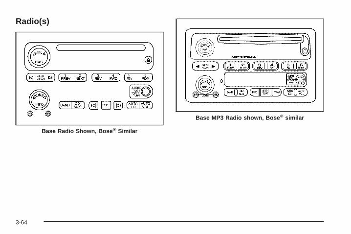
Radio(s)
Base Radio Shown, Bose® Similar
Base MP3 Radio shown, Bose® similar
3-64
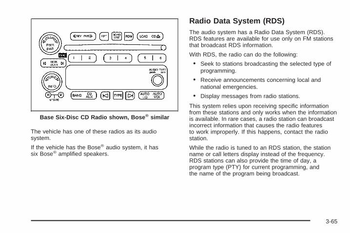
The vehicle has one of these radios as its audiosystem.
If the vehicle has the Bose® audio system, it hassix Bose® amplified speakers.
Radio Data System (RDS)The audio system has a Radio Data System (RDS).RDS features are available for use only on FM stationsthat broadcast RDS information.
With RDS, the radio can do the following:
• Seek to stations broadcasting the selected type ofprogramming.
• Receive announcements concerning local andnational emergencies.
• Display messages from radio stations.
This system relies upon receiving specific informationfrom these stations and only works when the informationis available. In rare cases, a radio station can broadcastincorrect information that causes the radio featuresto work improperly. If this happens, contact the radiostation.
While the radio is tuned to an RDS station, the stationname or call letters display instead of the frequency.RDS stations can also provide the time of day, aprogram type (PTY) for current programming, andthe name of the program being broadcast.
Base Six-Disc CD Radio shown, Bose® similar
3-65
Playing the Radio
PWR (Power): Push to turn the system on and off.
op VOL or VOLUME: Turn to increase or to decreasethe volume.
DISPL (Display) or INFO (Information): Press todisplay the time while the ignition is off.
For RDS, press to change the information while usingRDS. The display options are station name, RDS stationfrequency, PTY (program type), and the name of theprogram (if available).
For XM, press to retrieve four different categoriesof information related to the current song or channel:Artist, Song Title, Category or PTY, ChannelNumber/Channel Name.
To change the default on the display, press theDISPL or INFO knob until the desired display is shown,then briefly press and hold the knob until a beep isheard. The selected display becomes the default.
AUTO VOL (Automatic Volume): With automaticvolume, the audio system adjusts automatically to makeup for road and wind noise while driving by increasingthe volume as vehicle speed increases.
Set the volume at the desired level. Press this button toselect LOW, MEDIUM, or HIGH. AVOL, or dependingon the radio, MIN, MED, or MAX. AUTO VOL. Eachhigher setting provides more volume compensation atfaster vehicle speeds. On some radios, NONE maydisplay if the radio cannot determine the vehicle speed.To turn automatic volume off, press this button untilOFF, AVOL OFF, or AUTO VOL OFF displays.
3-66
Finding a Station
BAND: Press to choose between FM1, FM2, AM, orXM1 or XM2.
o TUNE p: Turn to select radio stations.
op / ©¨ SEEK: Press either SEEK arrow, ordepending on the radio, SEEK or TYPE arrow to goto the previous or to the next station and stay there.
The radio only seeks stations with a strong signal thatare in the selected band.
©SCAN ¨: Press and hold either SCAN arrow,or depending on the radio, SCAN or TYPE arrow brieflyuntil SCAN or SCN displays and a beep is heard.The radio goes to a station, plays for a few seconds,then goes to the next station. Press either arrow againto stop scanning.
To scan preset stations, press and hold either SCANarrow, or depending on the radio, SCAN or TYPE arrowfor more than four seconds. PSCN or PSC displays and adouble beep is heard. The radio goes to a preset station,plays for a few seconds, then goes to the next presetstation. Press either arrow again to stop scanningpresets.
The radio only scans stations with a strong signal that arein the selected band.
Setting Preset StationsUp to 30 stations (six FM1, six FM2, and six AM,six XM1 and six XM2, can be programed on thesix numbered pushbuttons, by performing thefollowing steps:
1. Turn the radio on.
2. Press BAND to select FM1, FM2, AM, or XM1or XM2.
3. Tune in the desired station.
4. Press and hold one of the six numberedpushbuttons until a beep sounds. When thatnumbered pushbutton is pressed, the stationthat was set, returns.
5. Repeat Steps 2 through 4 for each pushbutton.
To store an equalization setting to a preset stationperform the following:
1. Tune to the preset station.
2. Press and release the AUTO EQ button to selectthe equalization setting.Once the equalization no longer displays, theequalization is set for that preset station.
3-67
Setting the Tone(Bass/Midrange/Treble)AUDIO: Press and turn to adjust the Tone.1. Push and release until BASS, MID (midrange)
(without Bose®), or TREB (treble) displays.2. Turn to increase or to decrease the tone.
The display shows the bass, midrange (without Bose®),or treble level. If a station is weak or has static,decrease the treble.To adjust the bass, midrange (without Bose®), or trebleto the middle position while it is displayed, push andhold AUDIO. The radio produces one beep and adjuststhe display level to the middle position.To adjust all tone and speaker controls to the middleposition, push and hold AUDIO when no tone or speakercontrols displays. ALL CENTERED displays and abeep is heard.
AUTO EQ (Automatic Equalization): Press toselect customized equalization settings designed forcountry/western, jazz, talk, pop, rock, and classical.
To return the bass and treble to the manual mode,push and release this button until CUSTOM displays.
The radio saves separate AUTO EQ settings foreach preset and source.
If the radio has the Bose® audio system, the equalizationsettings are either CUSTOM or TALK.
Adjusting the Speakers (Balance/Fade)
AUDIO: Press and turn to adjust the speakers.
To adjust the balance between the right and the leftspeakers:
1. Push and release until BAL (balance) displays.
2. Turn to move the sound toward the right or the leftspeakers.
To adjust the fade between the front and rear speakers:
1. Push and release this knob until FADE or FADdisplays.
2. Turn to move the sound toward the front or the rearspeakers.
To adjust the balance or the fade to the middle positionwhile it is displayed, push and hold the AUDIO knob.On some radios, push the AUDIO knob, then pushit again and hold it until one beep is heard.
To adjust all tone and speaker controls to the middleposition, push and hold the AUDIO knob when no toneor speaker controls display. ALL CENTERED displaysand a beep is heard.
3-68
Finding a Program Type (PTY) Station(RDS and XM)To select and find a desired PTY
1. Press the TYPE button to activate program typeselect mode. TYPE or P-TYPE and the lastselected PTY displays.
2. Turn the TYPE knob or press and release theTYPE button to select a PTY.
3. Press either SEEK or TYPE arrow to select and togo to the PTY’s first station.
4. To go to another station within that PTY, press theTYPE button, then press either SEEK or TYPEarrow once.
5. Press either SEEK or TYPE arrow twice to exit theprogram type select mode.
If the radio cannot find the desired program type, NONEdisplays and the radio returns to the last station thatwas playing.
SCAN: To scan the stations within a PTY for all Radiosexcept the MP3 Radio:
1. Press the TYPE button to activate program typeselect mode. TYPE or P-TYPE and the lastselected PTY displays.
2. Turn the TYPE knob or press and release theTYPE button to select a PTY.
3. Once the desired PTY displays, press and holdeither SCAN or TYPE arrow for two seconds,and the radio begins scanning the stations inthe PTY.
4. Press either SCAN or TYPE arrow to stop scanning.
To select and find a desired PTY for the MP3 Radio:
1. Turn the P-TYPE knob to select a PTY.
2. Press the SEEK TYPE button to select and go tothe PTY’s first station.
3. Press the SEEK TYPE button twice to display thePTY and then go to another station.
4. Press the P-TYPE knob to exit program typeselect mode.IF PTY times out and no longer displays, go backto Step 1.
3-69
If both PTY and TRAF are on, the radio searchesfor stations with the selected PTY and trafficannouncements.
If the radio cannot find the desired program type, NONEdisplays and the radio returns to the last station.
BAND (Alternate Frequency): Alternate frequencylets the radio switch to a stronger station with the sameprogram type. To turn alternate frequency on, press andhold BAND for two seconds. AF ON displays. The radiocan switch to stations with a stronger frequency.
To turn alternate frequency off, press and hold BANDagain for two seconds. AF OFF displays. The radio doesnot switch to other stations.
This function does not apply for XM™ Satellite RadioService.
Setting Preset PTYs (RDS Only)For the Base Radio, pushbuttons have factory PTYpresets. Up to 12 PTYs (six FM1 and six FM2), canbe programmed on the six numbered pushbuttons,by performing the following steps:
1. Press BAND to select FM1 or FM2.
2. Press the TYPE button to activate program typeselect mode. P-TYPE and the last selected PTYdisplays.
3. Turn the TYPE knob or press and release theTYPE button to select a PTY.
4. Press and hold one of the six numberedpushbuttons until a beep sounds. When thatnumbered pushbutton is pressed (while in PTYmode), the PTY that was set, returns.
5. Repeat the steps for each pushbutton.
3-70
RDS Messages
ALERT! (MP3 Radio): Alert warns of local or nationalemergencies. When an alert announcement comeson the current radio station, ALERT! displays. Theannouncement is heard, even if the volume is low ora CD is playing. If a CD is playing, play stops duringthe announcement. Alert announcements cannotbe turned off.
ALERT! is not affected by tests of the emergencybroadcast system. This feature is not supported byall RDS stations.
TRAF (Traffic) (MP3 Radio): If TRAF displays, thetuned station broadcasts traffic announcements and thetraffic announcement is played when the tuned radiostation broadcasts one.
If the station does not broadcast traffic announcements,press the TRAF button and the radio seeks to a stationthat does. When a station that broadcasts trafficannouncements is found, the radio stops seeking andTRAF displays. If no station is found that broadcaststraffic announcements, No Traf displays.
If TRAF displays, press the TRAF button to turn off thetraffic announcements.
The radio plays the traffic announcement if the volume islow. The radio interrupts the play of a CD if the last tunedstation broadcasts traffic announcements.
This function does not apply to XM Satellite RadioService.
INFO (Information): If the current station has amessage, the information symbol or INFO displays.Press this button to see the message. The message candisplay the artist, song title, call in phone numbers, etc.
If the entire message is not displayed, parts of themessage appears every three seconds. To scroll throughthe message, press and release the INFO button. A newgroup of words displays after every press of this button.Once the complete message has displayed, theinformation symbol or INFO disappears from the displayuntil another new message is received. The last messageis displayed by pressing the INFO button. View the lastmessage until a new message is received or a differentstation is tuned to.
3-71
Radio Messages
CAL ERR (Calibration Error): Displays if the radio isno longer calibrated properly for the vehicle. The vehiclemust be returned to your dealer/retailer for service.
LOCKED: Displays when the THEFTLOCK® systemhas activated. Take the vehicle to your dealer/retailer forservice.
If any error occurs repeatedly, or if an error cannot becorrected, contact your dealer/retailer.
XM™ Satellite Radio ServiceXM is a satellite radio service that is based in the48 contiguous United States and 10 Canadian provinces.XM Satellite Radio has a wide variety of programmingand commercial-free music, coast-to-coast, and indigital-quality sound. During your trial or when yousubscribe, you will get unlimited access to XM RadioOnline for when you are not in the vehicle. A servicefee is required to receive the XM service. For moreinformation, contact XM at xmradio.com or call1-800-929-2100 in the U.S. and xmradio.ca orcall 1-877-438-9677 in Canada.
Radio Messages for XM OnlySee XM Radio Messages on page 3-84 later in thissection for further detail.
Playing a CDInsert a CD partway into the slot, label side up.The player pulls it in and the CD should begin playing.
For the Base Radio, first press the eject button orthe INFO knob to insert a CD with the ignition off.
If the ignition or radio is turned off, with a CD in theplayer, it stays in the player. When the ignition or radiois turned on, the CD starts playing where it stopped,if it was the last selected audio source.
When a CD is inserted, the CD symbol displays. Aseach new track starts to play, the track number displays.
The CD player can play the smaller 3 inch (8 cm)single CDs with an adapter ring. Full-size CDs andthe smaller CDs are loaded in the same manner.
3-72
Care of CDsSound quality can be reduced due to CD-R quality,the method of recording, the quality of the music that hasbeen recorded, and the way the CD-R has been handled.Handle them carefully. Store CD-R(s) in their originalcases or other protective cases and away from directsunlight and dust. The CD player scans the bottomsurface of the disc. If the surface of a CD is damaged,such as cracked, broken, or scratched, the CD does notplay properly or not at all. Do not touch the bottom sideof a CD while handling it; this could damage the surface.Pick up CDs by grasping the outer edges or the edge ofthe hole and the outer edge.
If the surface of a CD is soiled, take a soft, lint freecloth or dampen a clean, soft cloth in a mild, neutraldetergent solution mixed with water, and clean it.Make sure the wiping process starts from the centerto the edge.
Care of the CD and DVD PlayerDo not add a label to a CD, it could get caught in theCD player. If a CD is recorded on a personal computerand a description label is needed, try labeling the topof the recorded CD with a marking pen.
The use of CD lens cleaners for CDs is not advised, dueto the risk of contaminating the lens of the CD optics withlubricants internal to the CD and DVD player mechanism.
Notice: If a label is added to a CD, or more thanone CD is inserted into the slot at a time, or anattempt is made to play scratched or damaged CDs,the CD player could be damaged. While using the CDplayer, use only CDs in good condition without anylabel, load one CD at a time, and keep the CD playerand the loading slot free of foreign materials, liquids,and debris.
If an error displays, see “CD Messages” later in thissection.
For vehicles that have a radio with a Six-Disc CDplayer, see the following:
LOAD: Press to load CDs into the CD player.This CD player holds up to six CDs.
To insert one CD:
1. Turn the ignition on.
2. Press and release the LOAD button.
3. Wait for the indicator light, located to the right of theslot, to turn green.
4. Load a CD. Insert the CD part way into the slot,label side up. The player pulls the CD in.
3-73
To insert multiple CDs:
1. Turn the ignition on.
2. Press and hold the LOAD button for two seconds.A beep sounds and the indicator light, locatedto the right of the slot, begins to flash andMULTI LOAD # displays.
3. Once the light stops flashing and turns green,INSERT CD # displays, load a CD. Insert theCD part way into the slot, label side up.The player pulls the CD in.Once the CD is loaded, the indicator light beginsflashing again. Once the light stops flashingand turns green, load another CD. The CD playertakes up to six CDs. Do not try to load morethan six.
To load more than one CD but less than six, completeSteps 1 through 3. When finished loading CDs, press theLOAD button to cancel the loading function. The radiobegins to play the last CD loaded.
If more than one CD has been loaded, a number foreach CD displays.
Playing a Specific Loaded CDFor every CD loaded, a number displays. To play aspecific CD, first press the CD AUX button (if not alreadyin CD mode), then press the numbered pushbuttonthat corresponds to the CD. A small bar displays underthe CD number that is playing and the track numberdisplays.
Z (Eject) (Base or MP3 Radio): Press to eject a CD.Eject can be activated with either the ignition or radiooff. CDs can be loaded with the radio and ignition off ifthis button is pressed first.
CD Z (Eject): Press to eject CD(s).
To eject the CD that is currently playing, press andrelease this button.
To eject multiple CDs:
1. Press and hold the Z button for two seconds.
A beep is heard and the indicator light, located tothe right of the slot, begins to flash and EJECT ALLdisplays.
2. Once the light stops flashing, REMOVE CD #displays. The CD ejects and can be removed.Once the CD is removed, the indicator light beginsflashing again and another CD ejects.
To stop ejecting the CDs, press the Z button.
3-74
If the CD is not removed, after 25 seconds, the CDautomatically pulls back into the player. If CD is pushedback into the player, before the 25-second time period iscomplete, the player senses an error and tries to eject theCD several times before stopping.
Do not repeatedly press the Z button to eject a CDafter pushing it in manually. The player’s 25-secondeject timer resets at each press of eject, causingthe player to not eject the CD until the 25-secondtime period has elapsed.
1 FLD x (Previous) (MP3 Radio): This pushbuttondoes not work while using a non-MP3 CD.
2 FLD w (Next) (MP3 Radio): This pushbutton doesnot work while using a non-MP3 CD.
1 PREV (Previous) (Base Radio): Press to go to thebeginning of the current track (if more than eight secondshave played), or to the beginning of the previous track(if less than eight seconds have played). TRACK andthe track number displays. If this pushbutton is held orpressed more than once, the player continues movingbackward through the CD.
2 NEXT (Base Radio): Press to go to the next track.TRACK and the track number displays. If this pushbuttonis held or pressed more than once, the player continuesmoving forward through the CD.
{ REV or 3 REV (Reverse): Press and hold toreverse quickly within a track.
For the Base Radio, press and hold for less thantwo seconds to reverse at six times the normal playingspeed. Press and hold it for more than two secondsto reverse at 17 times the normal playing speed.
Sound is heard at a reduced volume. Release thisbutton to play the passage. ET and/or the elapsedtime of the track displays.
FWD | or 4 FWD (Forward): Press and hold toadvance quickly within a track.
For the Base Radio, press and hold for less thantwo seconds to advance at six times the normal playingspeed. Press and hold it for more than two secondsto advance at 17 times the normal playing speed.
Sound is heard at a reduced volume. Release thisbutton to play the passage. ET and/or the elapsed timeof the track displays.
5 B (CD): Press to play a CD while listening to theradio. The CD symbol displays when a CD is loaded.
RPT (Repeat): With the repeat setting, one track or anentire CD can be repeated.
3-75
To use repeat, do the following:
• To repeat a track, press and release theRPT button. RPT displays. Press again toturn off repeat play.
• To repeat the CD, press and hold the RPT button fortwo seconds. RPT displays. Press again to turn offrepeat play.
6 RDM (Random) (Base Radio or MP3 Radio): Pressto hear the tracks in random, rather than sequential,order. RDM ON displays. RDM T or RDM and the tracknumber displays when each track starts to play. Pressagain to turn off random play. RDM OFF displays.
RDM (Random): With the random setting, trackscan be listened to in random, rather than sequential,order, on one CD or on all of the CDs. To use random,do one of the following:
• To play the tracks on the CD in random order,press and release the RDM button. RANDOM ONEdisplays. Press again to turn off random play.
• To play the tracks on all of the CDs that are loadedin random order, press and hold RDM for morethan two seconds. A beep sounds and RANDOMALL displays. Press again to turn off random play.
AUTO EQ (Automatic Equalization): Press toselect the equalization setting while playing a CD.The equalization is stored when a CD is played.For more information on AUTO EQ, see “AUTO EQ”listed previously in this section.
©¨ / o p SEEK: Press the left arrow to go to thestart of the current or to the previous track.
On some radios, pressing the left arrow, if more than10 seconds have played, goes to the start of thecurrent track.
Press the right arrow to go to the start of the next track.If either arrow is pressed more than once, the playercontinues moving backward or forward through the CD.
On some radios, pressing either arrow for more thantwo seconds scans the previous or next tracks at fiveto eight seconds per track. SCAN and the track numberdisplays.
©SCAN ¨: To scan one CD, press and hold eitherSCAN, or depending on the radio, the TYPE arrow formore than two seconds until SCAN or TRACK SCANdisplays and a beep is heard. The radio goes to the nexttrack, plays for 10 seconds, then goes to the next track.Press either SCAN or depending on the radio, TYPEarrow again, to stop scanning.
3-76
To scan all loaded CDs, press and hold either SCANarrow for more than four seconds until ALL CD SCANdisplays and a beep sounds. Use this feature to listen to10 seconds of the first track of each loaded CD. Presseither SCAN arrow again, to stop scanning.
o TUNE p (MP3 Radio): Turning this knob fast tracksreverse or advances through tracks. The track numberdisplays for each track.
DISPL (Display) or INFO (Information): Press to seehow long the current track has been playing. ET and/orthe elapsed time displays. To change the default on thedisplay, track, or elapsed time, press until the desireddisplay appears, then press and hold briefly until a beepsounds. The selected display becomes the default.
BAND: Press to listen to the radio when a CD isplaying. The inactive CD(s) remains inside the radiofor future listening.
CD AUX (Auxiliary): Press to play a CD while listeningto the radio, or to listen to an auxiliary source (such asrear seat entertainment, if equipped).
Using Song List ModeThe six-disc CD changer has a feature called song list.This feature is capable of saving 20 track selections.
To save tracks into the song list feature:
1. Turn the CD player on and load it with at least oneCD. See “LOAD CD” listed previously in this sectionfor more information.
2. Check to see that the CD changer is not in songlist mode. S-LIST should not appear on the display.If S-LIST displays, press the SONG LIST button toturn it off.
3. Select the desired CD by pressing the numberedpushbutton and then use the right SEEK or TYPEarrow to locate the track to be saved. The trackbegins to play.
4. Press and hold the SONG LIST button to save thetrack into memory. When SONG LIST is pressed,one beep sounds. After two seconds of continuouslypressing the SONG LIST button, two beeps soundto confirm the track has been saved.
5. Repeat Steps 3 and 4 for saving other selections.
S-LIST FULL displays if more than 20 selectionsare saved.
3-77
To play the song list, press the SONG LIST button.One beep sounds and S-LIST displays. The recordedtracks begin to play in the order they were saved.
Seek through the song list by using either SEEK orTYPE arrow. Seeking past the last saved track returnsto the first saved track.
To delete tracks from the song list:
1. Turn the CD player on.
2. Press the SONG LIST button to turn song list on.S-LIST displays.
3. Press either SEEK or TYPE arrow to select thedesired track to be deleted.
4. Press and hold the SONG LIST button fortwo seconds. When SONG LIST is pressed,one beep sounds. After two seconds of continuouslypressing the SONG LIST button, two beeps soundto confirm that the track has been deleted.
After a track has been deleted, the remaining tracksare moved up the list. When another track is added tothe song list, the track is added to the end of the list.
To delete the entire song list:
1. Turn the CD player on.
2. Press the SONG LIST button to turn song list on.S-LIST displays.
3. Press and hold the SONG LIST button for morethan four seconds. One beep sounds, followed bytwo beeps after two seconds, and a final beepsounds after four seconds. S-LIST EMPTY displaysindicating the song list has been deleted.
If a CD is ejected, and the song list contains savedtracks from that CD, those tracks are automaticallydeleted from the song list. Any tracks saved to the songlist again are added to the bottom of the list.
To end song list mode, press the SONG LIST button.One beep sounds and S-LIST is removed from thedisplay.
Playing an MP3/WMA CD-R DiscThe vehicle’s radio system may have the MP3/WMAfeature. If it has this feature, it is capable of playing anMP3/WMA CD-R disc. For more information on howto play an MP3/WMA CD-R disc, see Using an MP3 onpage 3-80 later in this section.
3-78
CD Messages
CHECK CD: If this message displays and/or the CDejects, it could be for one of the following reasons:
• It is very hot. When the temperature returnsto normal, the CD should play.
• The road is very rough. When the road becomessmoother, the CD should play.
• The CD is dirty, scratched, wet, or upside down.
• The air is very humid. If so, wait about an hour andtry again.
• There could have been a problem while burningthe CD.
• The label could be caught in the CD player.
If the CD is not playing correctly, for any other reason,try a known good CD.
If any error occurs repeatedly or if an error cannot becorrected, contact your dealer/retailer. If the radiodisplays an error message, write it down and provideit to your dealer/retailer when reporting the problem.
Listening to a DVDIf the vehicle has the Rear Seat Entertainment (RSE)system and a DVD is playing, the DVD symbol displaysindicating that the DVD is available and can be listened tothrough the vehicle’s speakers.
To listen to the DVD, press the CD AUX button untilRSE displays. The current radio source stops and theDVD sound comes through the speakers.
To stop listening to the DVD, press the CD AUX button,if a CD is loaded, or press the BAND button to selecta different source.
When the RSE system is turned off, the DVD symbolgoes off of the radio display and RSE OFF displays.The radio returns to the last radio source that wasplaying. See Rear Seat Entertainment (RSE) Systemon page 3-96 for more information.
3-79
Using an MP3
MP3/WMA Disc
MP3/WMA FormatIf you burn an MP3 disc on a personal computer:
• Make sure the MP3 files are recorded on aCD-R disc.
• Standard audio, MP3 files, and WMA files can bemixed on one CD.
• Make sure playlists have a .mp3 or .wpl extension,other file extensions might not work.
• Files can be recorded with a variety of fixed orvariable bit rates. Song title, artist name, and albumis available for display by the radio when recordedusing ID3 tags version 1 and 2.
• Create a folder structure that makes it easy to findsongs while driving. Organize songs by albums usingone folder for each album. Each folder or albumshould contain 18 songs or less.
• Make sure to finalize the disc when burning an MP3disc, using multiple sessions. It is usually better toburn the disc all at once.
The player is able to read and play a maximum of253 folders, 50 playlists, 20 sessions, and 949 files.Long file names, folder names, or playlist names
may use more disc memory space than necessary.To conserve space on the disc, minimize the length ofthe file, folder, or playlist names. An MP3 CD that wasrecorded using no file folders can also be played. Thesystem can support up to 11 folders in depth, though,keep the depth of the folders to a minimum in order tokeep down the complexity and confusion in trying tolocate a particular folder during playback. If a CDcontains more than the maximum of 253 folders,50 playlists, 20 sessions, and 949 files, the playerallows access and navigates up to the maximum,but all items over the maximum will not play.
Root DirectoryThe root directory is treated as a folder. If the rootdirectory has compressed audio files, the directorydisplays as F1 ROOT. All files contained directly underthe root directory are accessed prior to any root directoryfolders. However, playlists (Px) are always accessedbefore root folders or files.
Empty Directory or FolderIf a root directory or a folder exists somewhere in thefile structure that contains only folders/subfolders andno compressed files directly beneath them, the playeradvances to the next folder in the file structure thatcontains compressed audio files. The empty folderdoes not display.
3-80

No FolderWhen the CD contains only compressed files, the filesare located under the root folder. The next and previousfolder functions do not function on a CD that wasrecorded without folders or playlists. When displayingthe name of the folder the radio displays ROOT.
When the CD contains only playlists and compressedaudio files, but no folders, all files are located under theroot folder. The folder down and the folder up buttonssearch playlists (Px) first and then goes to the rootfolder. When the radio displays the name of the folderthe radio displays ROOT.
Order of PlayTracks are played in the following order:
• If CD audio tracks are available they will be playedfirst, otherwise play begins from the first track inthe first playlist and continues sequentially throughall tracks in each playlist. When the last track ofthe last playlist has played, play continues from thefirst track of the first playlist.
• If the CD does not contain any playlists, then playbegins from the first track under the root directory.When all tracks from the root directory have played,play continues from files according to their numericallisting. After playing the last track from the last folder,play begins again at the first track of the first folder orroot directory.
When play enters a new folder, the display does notautomatically show the new folder name unless thefolder mode has been chosen as the default display.See DISPL (display) later in this section for moreinformation. The new track name displays.
File System and NamingThe song name that displays is the song name that iscontained in the ID3 tag. If the song name is not presentin the ID3 tag, then the radio displays the file namewithout the extension (such as .mp3) as the track name.
Track names longer than 32 characters or four pagesare shortened. Parts of words on the last page oftext and the extension of the file name does not display.
Preprogrammed PlaylistsPreprogrammed playlists that were created usingWinAmp™, MusicMatch™, or Real Jukebox™ softwarecan be accessed, however, they cannot be editedusing the radio. These playlists are treated as specialfolders containing compressed audio song files.
3-81
Playing an MP3/WMAInsert a CD partway into the slot, label side up. Theplayer pulls it in, and READING displays. The CD shouldbegin playing and the CD symbol displays. To insert aCD while the ignition is off, first press the Z buttonor the DISPL knob.
If the ignition or radio is turned off with a CD in theplayer it stays in the player. When the ignition or radiois turned on, the CD starts to play where it stopped,if it was the last selected audio source.
As each new track starts to play, the track number andsong title displays.
1 FLD x (Previous Folder): Press to go to the firsttrack in the previous folder. Press 1 FLD x whilein folder random mode to go to the first track in theprevious folder and random the tracks in that folder.
2 FLD w (Next Folder): Press to go to the first trackin the next folder. Press 2 FLD w while in folder randommode to go to the first track in the next folder and randomthe tracks in that folder.
3 REV (Reverse): Press and hold to reverse quicklywithin a track. Press and hold 3 REV for less thantwo seconds to reverse at 10 times the normal playingspeed. Press and hold 3 REV for more than two secondsto reverse at 20 times the normal playing speed. Release3 REV to play the passage. REV and the elapsed time ofthe track displays.
4 FWD (Forward): Press and hold to advance quicklywithin a track. Press and hold 4 FWD for less thantwo seconds to advance at 10 times the normal playingspeed. Press and hold 4 FWD for more than two secondsto advance at 20 times the normal playing speed.Release 4 FWD to play the passage. FWD and theelapsed time of the track displays.
6 RDM (Random): Press and release to play thetracks of a current folder or playlist, in random order.FLDR RDM displays. Once all of the tracks a currentfolder or playlist have played the system moves on tothe next folder or playlist and play all of the tracks inrandom order.
To play all tracks on the CD in random order, press andhold 6 RDM for two seconds. A beep sounds and DISCRDM displays. This feature does not work with playlists.
When in random, press and release either SEEK arrow togo to the next or previous random track.
Press and release 6 RDM again to turn off random play.NO RDM displays.
3-82
o SEEK p: Press the left SEEK arrow to go to thestart of the previous track. Press the right SEEK arrow togo to the start of the next track. Press either SEEK arrowfor more than two seconds to search the previous or nexttracks at two tracks per second. Release the button tostop searching and to play the track.
o TUNE p: Turn to fast track reverse oradvance through the tracks in all folders or playlists.The track number and file name displays for each track.Turn o TUNE p while in random to fast track reverse oradvance the tracks in sequential order.
DISPL (Display): Press to switch between track mode,folder/playlist mode, and time of day mode. The displayshows only eight characters, but there can be up tofour pages of text. If there are more than eight charactersin the song, folder, or playlist name, they are displayedif DISPL is not pressed again, pressing DISPL withintwo seconds goes to the next display mode.
• Track mode displays the current track number andthe ID3 tag song name.
• Folder/playlist mode displays the current folder orplaylist number and the folder/playlist name.
• Time of day mode displays the time of day and theID3 tag song name.
To change the default on the display, press the DISPLknob until the desired display appears, then press andhold this knob for two seconds. The radio producesone beep and the selected display becomes the default.
INFO (Information): INFO displays when a currenttrack has ID3 tag information. Press INFO to displaythe artist name and album contained in the tag. INFOdisappears from the display when the information in theID3 tag has finished.
BAND: Press to listen to the radio when a CD isplaying. The inactive CD remains inside the radio forfuture listening.
CD AUX (Auxiliary): Press to play a CD when listeningto the radio. The CD symbol displays when a CD isloaded.
Z (Eject): Press to eject a CD. Eject can activatewhile either the ignition or the radio is off. CDs can beloaded while the ignition and the radio is off if this buttonis pressed first.
3-83
XM Radio Messages
xL (Explicit Language Channels): These channels,or any others, can be blocked by calling1-800-852-XMXM (9696).
Updating: The encryption code in the receiver is beingupdated, and no action is required. This process shouldtake no longer than 30 seconds.
No Signal: The system is functioning correctly, but thevehicle is in a location that is blocking the XM signal.When the vehicle is moved into an open area, thesignal should return.
No Signl: The system is functioning correctly, but thevehicle is in a location that is blocking the XM signal.When the vehicle is moved into an open area, thesignal should return.
Loading XM: The audio system is acquiring andprocessing audio and text data. No action is needed.This message should disappear shortly.
Loading: The radio system is acquiring and processingaudio and text data. No action is needed. This messageshould disappear shortly.
CH Off Air: This channel is not currently in service.Tune in to another channel.
Off Air: This channel is not currently in service. Tuneto another channel.
CH Unauth: This channel is blocked or cannot bereceived with your XM Subscription package.
Unauth: This channel is blocked or cannot be receivedwith your XM Subscription package.
CH Unavail: This previously assigned channel is nolonger assigned. Tune to another station. If this stationwas one of the presets, choose another station forthat preset button.
CH Unavl: This previously assigned channel is nolonger assigned. Tune to another station. If this stationwas one of the presets, choose another station forthat preset button.
No Info: No artist, song title, category, or textinformation is available at this time on this channel.The system is working properly.
Not Found: There are no channels available for theselected category. The system is working properly.
XM Locked: The XM receiver in the vehicle mayhave previously been in another vehicle. For securitypurposes, XM receivers cannot be swapped betweenvehicles. If this message is received after having thevehicle serviced, check with your dealer/retailer.
3-84

XM Lock: The XM receiver in your vehicle couldhave previously been in another vehicle. For securitypurposes, XM receivers cannot be swapped betweenvehicles. If this message is received after having yourvehicle serviced, check with your dealer/retailer.
Radio ID: If tuned to channel 0, there could be areceiver fault., this message will alternate with the XMRadio 8 digit radio ID label. This label is needed toactivate the service. Consult with your dealer/retailer.
Unknown: If this message is received when tunedto channel 0, there could be a receiver fault. Consultwith your dealer/retailer.
Chk XMRcvr: If this message does not clear withina short period of time, the receiver may have afault. Consult with your dealer/retailer.
Check XM: If this message does not clear withina short period of time, the receiver could have afault. Consult with your dealer/retailer.
Navigation/Radio SystemFor vehicles with a navigation radio system, see theseparate Navigation System manual.
Bluetooth®
Vehicles with a Bluetooth system can use a Bluetoothcapable cell phone with a Hands Free Profile to make andreceive phone calls. The system can be used while thekey is in ON/RUN or ACC/ACCESSORY position. Therange of the Bluetooth system can be up to 30 ft. (9.1 m).Not all phones support all functions, and not all phonesare guaranteed to work with the in-vehicle Bluetoothsystem. See gm.com/bluetooth for more informationon compatible phones.
Voice RecognitionThe Bluetooth system uses voice recognition to interpretvoice commands to dial phone numbers and name tags.
Noise: Keep interior noise levels to a minimum.The system may not recognize voice commands ifthere is too much background noise.
When to Speak: A short tone sounds after the systemresponds indicating when it is waiting for a voicecommand. Wait until the tone and then speak.
How to Speak: Speak clearly in a calm and naturalvoice.
3-85
Audio SystemWhen using the in-vehicle Bluetooth system, soundcomes through the vehicle’s front audio system speakersand overrides the audio system. Use the audio systemvolume knob, during a call, to change the volume level.The adjusted volume level remains in memory for latercalls. To prevent missed calls, a minimum volume levelis used if the volume is turned down too low.
Bluetooth Controls
Use the g button located on the steering wheel tooperate the in-vehicle Bluetooth system. See AudioSteering Wheel Controls on page 3-109 for moreinformation.
g (Push To Talk): Press to answer incoming calls,to confirm system information, and to start speechrecognition.
PairingA Bluetooth enabled cell phone must be paired to thein-vehicle Bluetooth system first and then connected tothe vehicle before it can be used. See the cell phonemanufacturers user guide for Bluetooth functions beforepairing the cell phone. If a Bluetooth phone is notconnected, calls will be made using OnStar® Hands-FreeCalling, if available. Refer to the OnStar owner’s guide formore information.
Pairing Information:
• Up to five cell phones can be paired to the in-vehicleBluetooth system.
• The pairing process is disabled when the vehicle ismoving.
• The in-vehicle Bluetooth system automatically linkswith the first available paired cell phone in theorder the phone was paired.
• Only one paired cell phone can be connected to thein-vehicle Bluetooth system at a time.
• Pairing should only need to be completed once,unless changes to the pairing information havebeen made or the phone is deleted.
To link to a different paired phone, see Linking to aDifferent Phone later in this section.
3-86
Pairing a Phone
1. Press and hold g for two seconds. The systemresponds with “Ready” followed by a tone.
2. Say “Bluetooth”. The system responds with“Bluetooth ready” followed by a tone.
3. Say “Pair”. The system responds with instructionsand a four digit PIN number. The PIN number willbe used in Step 4.
4. Start the Pairing process on the cell phone that willbe paired to the vehicle. Reference the cell phonemanufacturers user guide for information onthis process.Locate the device named “General Motors” in thelist on the cellular phone and follow the instructionson the cell phone to enter the four digit PIN numberthat was provided in Step 3.
5. The system prompts for a name for the phone.Use a name that best describes the phone.This name will be used to indicate which phoneis connected. The system then confirms the nameprovided.
6. The system responds with “<Phone name> hasbeen successfully paired” after the pairing processis complete.
7. Repeat Steps 1 through 7 for additional phones tobe paired.
Listing All Paired and Connected Phones
1. Press and hold g for two seconds. The systemresponds with “Ready” followed by a tone.
2. Say “Bluetooth”. The system responds with“Bluetooth ready” followed by a tone.
3. Say “List”. The system lists all the paired Bluetoothdevices. If a phone is connected to the vehicle,the system will say “Is connected” after theconnected phone.
Deleting a Paired Phone
1. Press and hold g for two seconds. The systemresponds with “Ready” followed by a tone.
2. Say “Bluetooth”. The system responds with“Bluetooth ready” followed by a tone.
3. Say “Delete”. The system asks which phone todelete followed by a tone.
4. Say the name of the phone to be deleted. If thephone name is unknown, use the “List” commandfor a list of all paired phones. The system respondswith “Would you like to delete <phone name>?Yes or No” followed by a tone
5. Say “Yes” to delete the phone. The systemresponds with “OK, deleting <phone name>”.
3-87
Linking to a Different Phone
1. Press and hold g for two seconds. The systemresponds with “Ready” followed by a tone.
2. Say “Bluetooth”. The system responds with“Bluetooth ready” followed by a tone.
3. Say “Change phone”. The system responds with“Please wait while I search for other phones”.
• If another phone is found, the response will be“<Phone name> is now connected”.
• If another phone is not found, the original phoneremains connected.
Storing Name TagsThe system can store up to thirty phone numbers asname tags that are shared between the Bluetooth andOnStar systems.
The system uses the following commands to store andretrieve phone numbers:
• Store
• Digit Store
• Directory
Using the Store CommandThe store command allows a phone number to bestored without entering the digits individually.
1. Press and hold g for two seconds. The systemresponds with “Ready” followed by a tone.
2. Say “Store”. The system responds with“Store, number please” followed by a tone.
3. Say the complete phone number to be stored atonce with no pauses.
• If the system recognizes the number it respondswith “OK, Storing” and repeats the phone number.
• If the system is unsure it recognizes the phonenumber, it responds with “Store” and repeats thenumber followed by “Please say yes or no”. If thenumber is correct, say “Yes”. If the number is notcorrect, say “No”. The system will ask for thenumber to be re-entered.
4. After the system stores the phone number, itresponds with “Please say the name tag” followedby a tone.
3-88

5. Say a name tag for the phone number. The nametag is recorded and the system responds with“About to store <name tag>. Does that sound OK?”.
• If the name tag does not sound correct, say“No” and repeat Step 5.
• If the name tag sounds correct, say “Yes” andthe name tag is stored. After the number isstored the system returns to the main menu.
Using the Digit Store CommandThe digit store command allows a phone number to bestored by entering the digits individually.
1. Press and hold g for two seconds. The systemresponds with “Ready” followed by a tone.
2. Say “Digit Store”. The system responds with“Please say the first digit to store” followedby a tone.
3. Say the first digit to be stored. The system willrepeat back the digit it heard followed by a tone.Continue entering digits until the number to bestored is complete.
• If an unwanted number is recognized by thesystem, say “Clear” at any time to clear thelast number.
• To hear all of the numbers recognized by thesystem, say “Verify” at any time and thesystem will repeat them.
4. After the complete number has been entered, say“Store”. The system responds with “Please say thename tag” followed by a tone.
5. Say a name tag for the phone number. The nametag is recorded and the system responds with“About to store <name tag>. Does that sound OK?”.
• If the name tag does not sound correct, say“No” and repeat Step 5.
• If the name tag sounds correct, say “Yes” andthe name tag is stored. After the number isstored the system returns to the main menu.
Using the Directory CommandThe directory command lists all of the name tags storedby the system. To use the directory command:
1. Press and hold g for two seconds. The systemresponds with “Ready” followed by a tone.
2. Say “Directory”. The system responds with“Directory” and then plays back all of the storedname tags. When the list is complete, the systemreturns to the main menu.
3-89
Deleting Name TagsThe system uses the following commands to deletename tags:
• Delete
• Delete all name tags
Using the Delete CommandThe delete command allows specific name tags to bedeleted.
To use the delete command:
1. Press and hold g for two seconds. The systemresponds with “Ready” followed by a tone.
2. Say “Delete”. The system responds with “Delete,please say the name tag” followed by a tone.
3. Say the name tag to be deleted. The systemresponds with “Would you like to delete,<name tag>? Please say yes or no”.
• If the name tag is correct, say “Yes” to deletethe name tag. The system responds with “OK,deleting <name tag>, returning to the main menu.”
• If the name tag is incorrect, say “No”. The systemresponds with “No. OK, let’s try again, please saythe name tag.”
Using the Delete All Name Tags CommandThe delete all name tags command deletes all storedphone book name tags and route name tags for OnStar(if present).
To use the delete all name tags command:
1. Press and hold g for two seconds. The systemresponds with “Ready” followed by a tone.
2. Say “Delete all name tags”. The system respondswith “You are about to delete all name tags storedin your phone directory and your route destinationdirectory. Are you sure you want to do this? Pleasesay yes or no.”
• Say “Yes” to delete all name tags.
• Say “No” to cancel the function and return to themain menu.
Making a CallCalls can be made using the following commands:
• Dial
• Digit Dial
• Call
• Re-dial
3-90

Using the Dial Command
1. Press and hold g for two seconds. The systemresponds with “Ready” followed by a tone.
2. Say “Dial”. The system responds with “Dial using<phone name>. “Number please” followed bya tone.
3. Say the entire number without pausing.
• If the system recognizes the number, it respondswith “OK, Dialing” and dials the number.
• If the system does not recognize the number,it confirms the numbers followed by a tone.If the number is correct, say “Yes”. The systemresponds with “OK, Dialing” and dials the number.If the number is not correct, say “No”. The systemwill ask for the number to be re-entered.
Using the Digit Dial Command
1. Press and hold g for two seconds. The systemresponds with “Ready” followed by a tone.
2. Say “Digit Dial”. The system responds with “Digitdial using <phone name>, please say the first digitto dial” followed by a tone.
3. Say the digit to be dialed one at a time. Followingeach digit, the system will repeat back the digit itheard followed by a tone.
4. Continue entering digits until the number to bedialed is complete. After the whole number hasbeen entered, say “Dial”. The system respondswith “OK, Dialing” and dials the number.
• If an unwanted number is recognized by thesystem, say “Clear” at any time to clear thelast number.
• To hear all of the numbers recognized by thesystem, say “Verify” at any time and thesystem will repeat them.
3-91
Using the Call Command
1. Press and hold g for two seconds. The systemresponds with “Ready” followed by a tone.
2. Say “Call”. The system responds with “Call using<phone name>. Please say the name tag” followedby a tone.
3. Say the name tag of the person to call.
• If the system clearly recognizes the name tag itresponds with “OK, calling, <name tag>” anddials the number.
• If the system is unsure it recognizes the rightname tag, it confirms the name tag followed bya tone. If the name tag is correct, say “Yes”. Thesystem responds with “OK, calling, <name tag>”and dials the number. If the name tag is notcorrect, say “No”. The system will ask for thename tag to be re-entered.
Once connected, the person called will be heardthrough the audio speakers.
Using the Re-dial Command
1. Press and hold g for two seconds. The systemresponds with “Ready” followed by a tone.
2. After the tone, say “Re-dial”. The system respondswith “Re-dial using <phone name>” and dials thelast number called from the connected Bluetoothphone.
Once connected, the person called will be heardthrough the audio speakers.
Receiving a CallWhen an incoming call is received, the audio systemmutes and a ring tone is heard in the vehicle.Press g and begin speaking to answer the call.
Call WaitingCall waiting must be supported on the Bluetooth phoneand enabled by the wireless service carrier to work.
• Press g to answer an incoming call when anothercall is active. The original call is placed on hold.
• Press g again to return to the original call.
• To ignore the incoming call, continue with theoriginal call with no action.
3-92
Three-Way CallingThree-Way Calling must be supported on the Bluetoothphone and enabled by the wireless service carrierto work.
1. While on a call press g . The system respondswith “Ready” followed by a tone.
2. Say “Three-way call”. The system responds with“Three-way call, please say dial or call”.
3. Use the dial or call command to dial the number ofthe third party to be called.
4. Once the call is connected, press g to link all thecallers together.
Ending a CallTo end a call:
1. Press g . The system responds with “Ready”followed by a tone.
2. Say “End Call”. The call is then ended.
Muting a CallDuring a call, all sounds from inside the vehicle can bemuted so that the person on the other end of thecall cannot hear them.
To Mute a call
1. Press g . The system responds with “Ready”followed by a tone.
2. Say “Mute Call”. The system responds with“Call muted”.
To Cancel Mute
1. Press g . The system responds with “Ready”followed by a tone.
2. After the tone, say “Mute Call”. The systemresponds with “Resuming call”.
Transferring a CallAudio can be transferred between the in-vehicleBluetooth system and the cell phone.
To Transfer Audio to the Cell PhoneDuring a call with the audio in the vehicle:
1. Press g . The system responds with “Ready”followed by a tone.
2. Say “Transfer Call.” The system responds with“Transferring call” and the audio will switch fromthe vehicle to the cell phone.
3-93

To Transfer Audio to the In-VehicleBluetooth SystemThe cellular phone must be paired and connected withthe Bluetooth system before a call can be transferred.The connection process can take up to two minutes afterthe key is turned to the ON/RUN or ACC/ACCESSORYposition.
During a call with the audio on the cell phone,press g for more than two seconds. The audioswitches from the cell phone to the vehicle.
Voice Pass-ThruVoice Pass-Thru allows access to the voice recognitioncommands on the cell phone. See the cell phonemanufacturers user guide to see if the cell phonesupports this feature. This feature can be used toverbally access contacts stored in the cell phone.
1. Press and hold g for two seconds. The systemresponds with “Ready” followed by a tone.
2. Say “Bluetooth”. The system responds with“Bluetooth ready” followed by a tone.
3. Say “Voice”. The system responds with“OK, accessing <phone name>”.
• The cell phone’s normal prompt messages willgo through its cycle according to the phone’soperating instructions.
Dual Tone Multi-Frequency (DTMF)TonesThe in-vehicle Bluetooth system can send numbers andnumbers stored as name tags during a call. This is usedwhen calling a menu driven phone system. Accountnumbers can be programmed into the phonebookfor retrieval during menu driven calls.
Sending a Number During a Call
1. Press g . The system responds with “Ready”followed by a tone.
2. Say “Dial”. The system responds with “Say anumber to send tones” followed by a tone.
3. Say the number to send.
• If the system clearly recognizes the number itresponds with “OK, Sending Number” and thedial tones are sent and the call continues.
• If the system is not sure it recognized thenumber properly, it responds “Dial Number,Please say yes or no?” followed by a tone.If the number is correct, say “Yes”. The systemresponds with “OK, Sending Number” andthe dial tones are sent and the call continues.
3-94
Sending a Stored Name Tag During a Call
1. Press g . The system responds with “Ready”followed by a tone.
2. Say “Send name tag.” The system responds with“Say a name tag to send tones” followed by a tone.
3. Say the name tag to send.
• If the system clearly recognizes the name tag itresponds with “OK, Sending <name tag>” andthe dial tones are sent and the call continues.
• If the system is not sure it recognized the nametag properly, it responds “Dial <name tag>,Please say yes or no?” followed by a tone.If the name tag is correct, say “Yes”. The systemresponds with “OK, Sending <name tag>” andthe dial tones are sent and the call continues.
Clearing the SystemUnless information is deleted out of the in-vehicleBluetooth system, it will be retained indefinitely.This includes all saved name tags in the phonebookand phone pairing information. For information onhow to delete this information, see the above sectionson Deleting a Paired Phone and Deleting Name Tags.
Other InformationThe Bluetooth® word mark and logos are owned by theBluetooth® SIG, Inc. and any use of such marks byGeneral Motors is under license. Other trademarksand trade names are those of their respective owners.
This device complies with Part 15 of the FCC Rules.Operation is subject to the following two conditions:
1. This device may not cause harmful interference.
2. This device must accept any interference received,including interference that may cause undesiredoperation.
This device complies with RSS-210 of Industry Canada.Operation is subject to the following two conditions:
1. This device may not cause interference.
2. This device must accept any interference received,including interference that may cause undesiredoperation of the device.
Changes or modifications to this system by other thanan authorized service facility could void authorization touse this equipment.
3-95
Rear Seat Entertainment (RSE)SystemThe vehicle may have a DVD Rear SeatEntertainment (RSE) system. The RSE systemincludes a DVD player, a video display screen,two sets of wireless headphones, and a remotecontrol.
Before You DriveThe RSE system is for rear seat passengers only and isnot intended for the driver while driving.
Parental ControlThis button is located behind the video screen. Pressthis button while a DVD or CD is playing to freeze thevideo and mute the audio. The video screen displaysParental Control ON and the power indicator light onthe DVD player flashes. It also disables all other buttonoperations from the remote control and the DVD player,with the exception of the eject button. Press this buttonagain to restore operation of the DVD player.
This button can also be used to turn the DVD playerpower on and automatically resume play if the ignitionis in RUN, ACCESSORY, or if Retained AccessoryPower (RAP) is active.
HeadphonesThe RSE system includes two sets of wirelessheadphones.
Each set of headphones has an ON/OFF control.An indicator light illuminates on the headphones whenthey are on. If the light does not illuminate, the batteriesmay need to be replaced. See “Battery Replacement”following for more information.
Each set of headphones has a volume knob. To adjustthe volume, adjust this knob.
The transmitters are located below the video displayscreen. The headphones shut off automatically ifthey lose the signal from the system after aboutfour minutes to save battery power. The signal canbe lost if the system is turned off or if the headphonesare out of range of the transmitters.
When using the wired headphones, if the front seatpassengers play a CD in the Radio with Six-Disc CDor use XM Satellite Radio Service, audio is heardfrom these sources, instead of the DVD or CD thatis currently playing through the RSE.
Notice: Do not store the headphones in heat ordirect sunlight. This could damage the headphonesand repairs will not be covered by the warranty.Storage in extreme cold can weaken the batteries.Keep the headphones stored in a cool, dry place.
3-96

Both sets of rear seat headphones may include foamear pads.
The foam ear pads can become worn or damaged ifthey are not handled or stored properly. They canbe replaced separately from the headphone set.
The headphone replacement foam ear pads can beordered in pairs. See your dealer/retailer for moreinformation.
Battery ReplacementTo change the batteries on the headphones:
1. Loosen the screw to the battery door on the leftside of the headphones and slide open.
2. Replace the two batteries in the compartment.Install correctly using the diagram on the insideof the battery compartment.
3. Replace the battery door and tighten the doorscrew.
If the headphones are to be stored for a long period oftime, remove the batteries and keep them in a cool,dry place.
Stereo RCA JacksThe RCA jacks are located behind the video screen.The RCA jacks allow audio and video signals to beconnected from an auxiliary device such as a camcorderor a video game unit to the RSE system. Standard RCAcables, not included, are needed to connect the auxiliarydevice to the RCA jacks. The yellow connector inputsvideo and the red and white connectors input right andleft audio. Refer to the manufacturer’s instructions forproper connection of the auxiliary device.
To use the auxiliary inputs on the RSE system, connectan external auxiliary device to the color-coded RCA jacksand turn both the auxiliary device and the RSE systempower on. If the RSE system had been previously in theDVD player mode, pressing the SRCE button on thefaceplate or the remote control switches the RSE systembetween the auxiliary device and the DVD player.
3-97

How to Change the Video Format when inthe Auxiliary ModeThe auxiliary input video format is preset to NTSC.In some countries, the video format may be in thePAL system. To change the video format:
1. Press the z display menu button.
2. Press the down q navigation arrow to highlight theVideo Format option.
3. Press the r button to select Video Format.
4. Press the left p or right o navigation arrows toselect the desired video format.
5. Press the r button to accept the change.
Audio OutputAudio from the DVD player or auxiliary inputs can beheard through the following possible sources:
• Wireless Headphones
• Vehicle Speakers
• Vehicle wired headphone jacks on the Rear SeatAudio system (if equipped)
The RSE system always transmits the audio signal tothe wireless headphones, if there is audio available.See “Headphones” earlier in this section for moreinformation.
The RSE system is capable of outputting audio to thevehicle speakers by using the radio. The RSE system canbe selected as an audio source on the radio if the RSEsystem power is on. Once the RSE system is selected asan audio source on the radio, adjust the speaker volumeon the radio, if necessary. If the RSE system power is noton, the RSE system is not an available source on theradio. See the vehicle’s radio information.
The RSE system is capable of outputting audio to thewired headphone jacks on the rear seat audio system(if equipped). The RSE system can be selected asan audio source on the rear seat audio system if theRSE system power is on. See Rear Seat Audio (RSA)on page 3-108 for more information.
3-98

Video ScreenThe video screen is located in the overhead console.
To use the video screen:
1. Push forward on the release button located on theDVD display console.
2. Pull the screen down, away from you, and adjust itsposition as desired.
When the video screen is not in use, push it up into itslocked position.
If a DVD is playing and the screen is raised to its lockedposition, the screen shuts off, but the DVD continuesto play through the previous audio or video source.
The video screen contains the IR transmitters for thewireless headphones and the IR receivers for the remotecontrol. If the screen is in the closed position, the signalsare not available for the operation of the headphones orthe remote control.
Notice: Avoid directly touching the video screen,as damage may occur. See “Cleaning the VideoScreen” later in this section for more information.
DVD PlayerThe DVD player is located in the overhead console andis controlled by the buttons on the DVD player or onthe remote control. See “Remote Control” later inthis section for more information.The DVD player power can be turned on while theignition is in ON/RUN, ACC/ACCESSORY, or whenRetained Accessory Power (RAP) is active.The RSE system DVD player is only compatible withDVDs of the appropriate region code in the country thatthe vehicle was sold. The DVD region code is printedon the jacket of most DVDs.Standard audio CDs, CD-R, CD-RW, Video CD andPhoto CD/CD-R media are fully supported by this DVDplayer. DVD-R and DVD-RW media is supported ifformatted as DVD-Video. DVD+R and DVD+RW mediamay or may not be supported by the DVD player. TheDVD player does not support DVD-RAM, DVD-ROM,and DVD Audio media. An error message displays ifthis type of media is inserted into the DVD player.When using the wired headphones, not included, ifthe front seat passengers play a CD in the Radio withSix-Disc CD (if equipped) or use XM™ Satellite RadioService (if equipped), the audio for these sources will beheard, instead of the DVD or CD that is currently playingthrough the RSE.If an error message displays on the video screen, see“DVD Messages” later in this section.
3-99

DVD Player Buttons (Without Sunroof)
O (Power): Press to turn the RSE system on and off.The power indicator light illuminates when the poweris on.
X (Eject): Press to eject a DVD or CD.
SRCE (Source): Press to switch between the DVDplayer and an auxiliary source.
c (Stop): Press to stop playing, rewinding, or fastforwarding a DVD or CD. Press twice to return to thebeginning of the DVD.
s (Play/Pause): Press to start play of a DVD or CD.Press while a DVD or CD is playing to pause it.Press again to continue the play of the DVD or CD.
y (Main DVD Menu): Press to access the DVD menu.The DVD menu is different on every DVD. Use thenavigation arrows to move the cursor around the DVDmenu. After making a selection press the enter button.This button only operates when playing a DVD.
z (Set-up Menu): Press to adjust the color, tint,brightness, contrast, display mode, and dynamic rangecompression. The dynamic range compression featurecan be used to reduce loud audio and increase low audioproduced by some DVDs.
To change a feature back to the factory default setting,press this button to display the feature, then press andhold until the default setting displays.
While playing an Audio or DVD disc, press and hold z todisplay and to remove the track and time information.
n, q, p, o (Menu Navigation Arrows): Use thearrows to navigate through a menu.
r (Enter): Press to select the choices that arehighlighted in any menu.
3-100
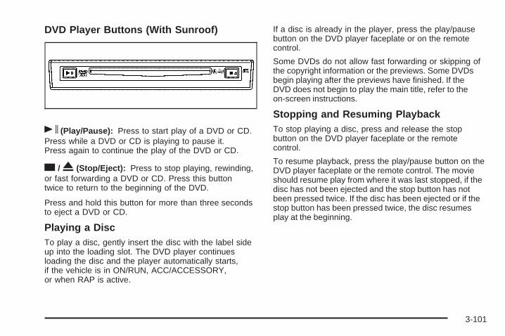
DVD Player Buttons (With Sunroof)
s (Play/Pause): Press to start play of a DVD or CD.Press while a DVD or CD is playing to pause it.Press again to continue the play of the DVD or CD.
c / X (Stop/Eject): Press to stop playing, rewinding,or fast forwarding a DVD or CD. Press this buttontwice to return to the beginning of the DVD.
Press and hold this button for more than three secondsto eject a DVD or CD.
Playing a DiscTo play a disc, gently insert the disc with the label sideup into the loading slot. The DVD player continuesloading the disc and the player automatically starts,if the vehicle is in ON/RUN, ACC/ACCESSORY,or when RAP is active.
If a disc is already in the player, press the play/pausebutton on the DVD player faceplate or on the remotecontrol.
Some DVDs do not allow fast forwarding or skipping ofthe copyright information or the previews. Some DVDsbegin playing after the previews have finished. If theDVD does not begin to play the main title, refer to theon-screen instructions.
Stopping and Resuming PlaybackTo stop playing a disc, press and release the stopbutton on the DVD player faceplate or the remotecontrol.
To resume playback, press the play/pause button on theDVD player faceplate or the remote control. The movieshould resume play from where it was last stopped, if thedisc has not been ejected and the stop button has notbeen pressed twice. If the disc has been ejected or if thestop button has been pressed twice, the disc resumesplay at the beginning.
3-101
Ejecting a Disc (DVD Player withoutSunroof)
Press the c / X button on the DVD player faceplateto eject the disc. There is not an eject button onthe remote control.
If a disc is ejected from the player, but is not removed,the DVD player reloads the disc after a short periodof time. The disc is stored in the DVD player. The DVDplayer does not resume play of the disc automatically.
Ejecting a Disc (DVD Player with Sunroof)
Press and hold the c / X button for more thantwo seconds on the DVD player faceplate to eject thedisc. There is not an eject button on the remote control.
If a disc is ejected from the player, but is not removed,the DVD player reloads the disc after a short periodof time. The disc is stored in the DVD player. The DVDplayer does not resume play of the disc automatically.
Remote ControlTo use the remote control, aim it at the transmitterwindow below the video screen and press the desiredbutton. Direct sunlight or very bright light can affectthe ability of the RSE system to receive signals fromthe remote control. If the remote control does not seemto be working, the batteries may need to be replaced.See “Battery Replacement” later in this section.
Objects blocking the line of sight can also affect thefunction of the remote control.
Notice: Storing the remote control in a hot area orin direct sunlight can damage it, and the repairs willnot be covered by the warranty. Storage in extremecold can weaken the batteries. Keep the remotecontrol stored in a cool, dry place.
3-102
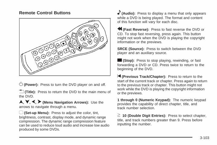
Remote Control Buttons
O (Power): Press to turn the DVD player on and off.
v (Title): Press to return the DVD to the main menu ofthe DVD.
n, q, p, o (Menu Navigation Arrows): Use thearrows to navigate through a menu.
z (Set-up Menu): Press to adjust the color, tint,brightness, contrast, display mode, and dynamic rangecompression. The dynamic range compression featurecan be used to reduce loud audio and increase low audioproduced by some DVDs.
e (Audio): Press to display a menu that only appearswhile a DVD is being played. The format and contentof this function will vary for each disc.
r (Fast Reverse): Press to fast reverse the DVD orCD. To stop fast reversing, press again. This buttonmight not work when the DVD is playing the copyrightinformation or the previews.
SRCE (Source): Press to switch between the DVDplayer and an auxiliary source.
c (Stop): Press to stop playing, rewinding, or fastforwarding a DVD or CD. Press twice to return to thebeginning of the DVD.
t (Previous Track/Chapter): Press to return to thestart of the current track or chapter. Press again to returnto the previous track or chapter. This button might notwork while the DVD is playing the copyright informationor the previews.
1 through 0 (Numeric Keypad): The numeric keypadprovides the capability of direct chapter, title, andtrack number selection.
} 10 (Double Digit Entries): Press to select chapter,title, and track numbers greater than 9. Press beforeinputting the number.
3-103

\ (Clear): Press within three seconds to clear anumber that has been entered.
P (Illumination): Press to turn the remote controlbacklight on. The backlight times out after about 7 to10 seconds if no other button is pressed while thebacklight is on.
y (Main DVD Menu): Press to access the DVD menu.The DVD menu is different on every DVD. Use thenavigation arrows to move the cursor around the DVDmenu. After making a selection press the enter button.This button only operates when playing a DVD.
r (Enter): Press to select the choices that arehighlighted in any menu.
q (Return): Press to exit the current active menuand return to the previous menu. This button operatesonly when a DVD is playing and a menu is active.
| (Camera Angle): Press to change camera angleson DVDs that have this feature when a DVD is playing.The format and content of this function will vary foreach disc.
{ (Subtitle): Press to turn on subtitles and to movethrough subtitle options when a DVD is playing. Theformat and content of this function will vary for each disc.
[ (Fast Forward): Press to fast forward the DVD orCD. To stop fast forwarding, press again. This buttonmight not work while the DVD is playing the copyrightinformation or the previews.
s (Play/Pause): Press to start play of a DVD or CD.Press while a DVD or CD is playing to pause it.Press again to continue the play of the DVD or CD.
When the DVD is playing, press this button then pressthe fast forward button. The DVD continues playingin a slow play mode. To cancel slow play mode, pressthis button.
u (Next Track/Chapter): Press to advance to thebeginning of the next track or chapter. This buttonmight not work when the DVD is playing the copyrightinformation or the previews.
3-104
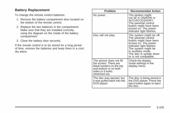
Battery ReplacementTo change the remote control batteries:
1. Remove the battery compartment door located onthe bottom of the remote control.
2. Replace the two batteries in the compartment.Make sure that they are installed correctly,using the diagram on the inside of the batterycompartment.
3. Close the battery door securely.
If the remote control is to be stored for a long periodof time, remove the batteries and keep them in a cool,dry place.
Problem Recommended ActionNo power. The ignition might
not be in ON/RUN orACC/ACCESSORY.The parental controlbutton might have beenturned on. The powerindicator light flashes.
Disc will not play. The system might be off.The parental controlbutton might have beenturned on. The powerindicator light flashes.The system might bein auxiliary mode.The disc is upside downor is not compatible.
The picture does not fillthe screen. There areblack borders on the topand bottom or on bothsides or it looksstretched out.
Check the displaymode settings in thedisplay menu.
The disc was ejected, butit was pulled back into theDVD player.
The disc is being stored inthe DVD player. Press theeject button again to ejectthe disc.
3-105

Problem Recommended ActionIn auxiliary mode, thepicture moves or scrolls.
Check the auxiliaryinput connections atboth devices.Change the Video Formatto PAL or NTSC. See“Stereo RCA Jacks”previously for how tochange the video format.
The language in the audioor on the screen is wrong.
Check the audio orlanguage selection inthe main DVD menu.
The remote control doesnot work.
Check to make sure thereis no obstruction betweenthe remote control andthe transmitter window.Check the batteries tomake sure they arenot dead or installedincorrectly.The parental controlbutton might have beenturned on. The powerindicator light flashes.
Problem Recommended ActionAfter stopping the player,I push Play butsometimes the DVDstarts where I left offand sometimes at thebeginning.
If the stop button waspressed one time, theDVD player resumesplaying where the DVDwas stopped. If the stopbutton was pressedtwo times the DVD playerbegins to play from thebeginning of the DVD.
The auxiliary source isrunning but there is nopicture or sound.
Check that the DVDplayer is in the auxiliarysource mode.Check the auxiliary inputconnections at bothdevices.
My disc is stuck in theplayer. The Load/Ejectbutton does not work.
Turn the DVD power off,then on, then press theload/eject button on theDVD player.Do not attempt to forciblyremove the disc from theDVD player. This couldpermanently damage thedisc and DVD player.
3-106

Problem Recommended ActionSometimes the wirelessheadphone audio cuts outor buzzes.
Check for obstructions,low batteries, receptionrange, and interferencefrom cellular telephonetowers or by using acellular telephone inthe vehicle.Check that theheadphones are facingthe front of the vehicle.
I lost the remote and/orthe headphones.
See your dealer/retailerfor assistance.
The DVD is playing, butthere is no picture orsound.
Check that the DVDplayer is in DVD mode.
The audio/video skips orjumps.
The DVD or CD couldbe dirty, scratched,or damaged.
The audio from the radiofor the Radio withSix-Disc CD and XM™has taken over the audiofrom the DVD or CDwhen using the wiredheadphones.
The RSE is workingcorrectly.Use the wirelessheadphones or have thefront seat passengerslisten to another audiosource.
DVD MessagesThe following errors can display on the video screen:
Disc Format Error: This message displays if a disc isinserted upside down, if the disc is not readable, orif the format is not compatible with the DVD player.
Load/Eject Error: This message displays if the disc isnot properly loaded or ejected.
Disc Play Error: This message displays if the DVDplayer cannot play the disc. Scratched or damaged discscause this error.
Region Code Error: This message displays if theregion code of the DVD is not compatible with the regioncode of the DVD player.
No Disc: This message displays if any of the buttonson the DVD faceplate or remote control are pressed andno disc is present in the DVD player.
DVD DistortionThere can be an experience with audio distortion in thewireless headphones when operating cellular phones,scanners, CB radios, Global Positioning Systems (GPS)*,two-way radios, mobile fax, or walkie talkies.It might be necessary to turn off the DVD player whenoperating one of these devices in or near the vehicle.
* Excludes the OnStar® System.
3-107

Cleaning the Video ScreenUse isopropyl or rubbing alcohol on a clean cloth andgently wipe the video screen. Do not spray directly ontothe screen and do not press too hard or too long onthe video screen.
Rear Seat Audio (RSA)This feature allows rear seat passengers to listen to anyof the sources: radio, CDs, or DVDs. However, the rearseat passengers can only control the sources that are notbeing listened by the front seat passengers. For example,rear seat passengers can listen to and control CDs orDVDs through the headphones while the driver listensto the radio through the front speakers. The rear seatpassengers have control of the volume for each setof headphones.
The front seat audio controls always have priority overthe RSA controls. If the front seat passengers switch thesource for the main radio to a remote source, the RSA isnot able to control the source. The rear seat audio can beoperated while the main radio is off.
P (Power): Press to turn the system on or off. Therear speakers are muted when the power is turned on.
u (Volume): Turn to increase or to decrease thevolume. The left volume knob controls the left wiredheadphones and the right volume knob controls theright wired headphones.
SRCE (Source): Press to select a source: radio, CD,or DVD. The inactive CD or DVD remains insidethe radio for future listening.
SEEK: Press to advance to the next station or trackand stay there. The display shows the selection. Thisfunction is inactive if the front seat passengers arelistening to the same audio source.
3-108
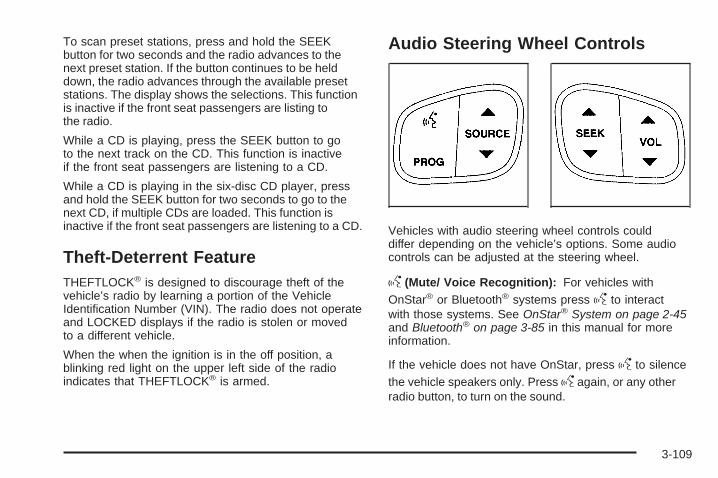
To scan preset stations, press and hold the SEEKbutton for two seconds and the radio advances to thenext preset station. If the button continues to be helddown, the radio advances through the available presetstations. The display shows the selections. This functionis inactive if the front seat passengers are listing tothe radio.
While a CD is playing, press the SEEK button to goto the next track on the CD. This function is inactiveif the front seat passengers are listening to a CD.
While a CD is playing in the six-disc CD player, pressand hold the SEEK button for two seconds to go to thenext CD, if multiple CDs are loaded. This function isinactive if the front seat passengers are listening to a CD.
Theft-Deterrent FeatureTHEFTLOCK® is designed to discourage theft of thevehicle’s radio by learning a portion of the VehicleIdentification Number (VIN). The radio does not operateand LOCKED displays if the radio is stolen or movedto a different vehicle.
When the when the ignition is in the off position, ablinking red light on the upper left side of the radioindicates that THEFTLOCK® is armed.
Audio Steering Wheel Controls
Vehicles with audio steering wheel controls coulddiffer depending on the vehicle’s options. Some audiocontrols can be adjusted at the steering wheel.
g (Mute/ Voice Recognition): For vehicles withOnStar® or Bluetooth® systems press g to interactwith those systems. See OnStar® System on page 2-45and Bluetooth® on page 3-85 in this manual for moreinformation.
If the vehicle does not have OnStar, press g to silencethe vehicle speakers only. Press g again, or any otherradio button, to turn on the sound.
3-109

PROG (Program): Press to play a station that hasbeen programmed on the radio preset pushbuttons.The radio seeks preset stations only with a strongsignal that are in the selected band.
When a CD is playing in the CD changer, press thisbutton to go to the next available CD, if multiple CDsare loaded.
Q SOURCE R: Press the SOURCE arrows to switchbetween FM1, FM2, AM, or XM1 or XM2, or a CD.If a CD is loaded the CD symbol displays.
Q SEEK R: Press the SEEK arrows to go to theprevious or the next radio station and stay there.The radio seeks stations only with a strong signalthat are in the selected band.
When a CD is playing, press the SEEK arrows to fastforward or reverse.
Q VOL R (Volume): Press the VOL arrows toincrease or to decrease the volume.
Radio ReceptionFrequency interference and static can occur duringnormal radio reception if items such as cell phonechargers, vehicle convenience accessories, and externalelectronic devices are plugged into the accessory poweroutlet. If there is interference or static, unplug the itemfrom the accessory power outlet.
AMThe range for most AM stations is greater than for FM,especially at night. The longer range can cause stationfrequencies to interfere with each other. For better radioreception, most AM radio stations boost the power levelsduring the day, and then reduce these levels during thenight. Static can also occur when things like storms andpower lines interfere with radio reception. When thishappens, try reducing the treble on the radio.
FM StereoFM signals only reach about 10 to 40 miles(16 to 65 km). Although the radio has a built-in electroniccircuit that automatically works to reduce interference,some static can occur, especially around tall buildingsor hills, causing the sound to fade in and out.
3-110
XM™ Satellite Radio ServiceXM Satellite Radio Service gives digital radio receptionfrom coast-to-coast in the 48 contiguous United States,and in Canada. Just as with FM, tall buildings or hills caninterfere with satellite radio signals, causing the sound tofade in and out. In addition, traveling or standing underheavy foliage, bridges, garages, or tunnels may causeloss of the XM signal for a period of time.
Cellular Phone UsageCellular phone usage may cause interference with thevehicle’s radio. This interference may occur when makingor receiving phone calls, charging the phone’s battery,or simply having the phone on. This interference causesan increased level of static while listening to the radio.If static is received while listening to the radio, unplugthe cellular phone and turn it off.
Fixed Mast AntennaThe fixed mast antenna can withstand most car washeswithout being damaged. If the mast becomes slightlybent, straighten it out by hand. If the mast is badly bent,replace it.
Occasionally check to make sure the antenna istightened to its base. If tightening is required, tightenby hand until fully seated plus one quarter turn.
XM™ Satellite Radio AntennaSystemThe XM Satellite Radio antenna is located on the roof ofthe vehicle. Keep the antenna clear of obstructions forclear radio reception.
If the vehicle has a sunroof, the performance of the XMsystem may be affected if the sunroof is open.
Chime Level AdjustmentThe radio is used to adjust the vehicle’s chime level.To change the volume level of the chime, press and holdpushbutton 6 with the ignition on and the radio power off.The volume level will change from the normal level toloud, and LOUD CHIME will appear on the radio display.To change back to the default or normal setting, pressand hold pushbutton 6 again. The volume level willchange from the loud level to normal, and NORMALCHIME will appear on the radio display. Removing theradio and not replacing it with a factory radio or chimemodule will disable vehicle chimes.
3-111

✍ NOTES
3-112

Your Driving, the Road, and the Vehicle ............4-2Driving for Better Fuel Economy .......................4-2Defensive Driving ...........................................4-2Drunk Driving .................................................4-3Control of a Vehicle ........................................4-3Braking .........................................................4-4Antilock Brake System (ABS) ...........................4-5Braking in Emergencies ...................................4-6StabiliTrak® System ........................................4-6Locking Rear Axle ........................................4-10All-Wheel Drive (AWD) System .......................4-10Steering ......................................................4-10Off-Road Recovery .......................................4-12Passing .......................................................4-12Loss of Control .............................................4-12Competitive Driving .......................................4-14Off-Road Driving ...........................................4-14Driving at Night ............................................4-27
Driving in Rain and on Wet Roads ..................4-27Before Leaving on a Long Trip .......................4-28Highway Hypnosis ........................................4-28Hill and Mountain Roads ................................4-29Winter Driving ..............................................4-30If Your Vehicle is Stuck in Sand, Mud,
Ice, or Snow .............................................4-32Rocking Your Vehicle to Get It Out .................4-32Recovery Hooks ...........................................4-32Loading the Vehicle ......................................4-33Adding a Snow Plow or Similar Equipment .......4-39
Towing ..........................................................4-40Towing Your Vehicle .....................................4-40Recreational Vehicle Towing ...........................4-40Electronically Controlled Air Suspension
System ....................................................4-47Towing a Trailer ...........................................4-48
Section 4 Driving Your Vehicle
4-1

Your Driving, the Road, andthe Vehicle
Driving for Better Fuel EconomyDriving habits can affect fuel mileage. Here are somedriving tips to get the best fuel economy possible.
• Avoid fast starts and accelerate smoothly.
• Brake gradually and avoid abrupt stops.
• Avoid idling the engine for long periods of time.
• When road and weather conditions are appropriate,use cruise control, if equipped.
• Always follow posted speed limits or drive moreslowly when conditions require.
• Keep vehicle tires properly inflated.
• Combine several trips into a single trip.
• Replace the vehicle’s tires with the same TPC Specnumber molded into the tire’s sidewall near the size.
• Follow recommended scheduled maintenance.
Defensive DrivingDefensive driving means “always expect theunexpected.” The first step in driving defensively is towear your safety belt — See Safety Belts: They Are forEveryone on page 1-13.
{CAUTION:
Assume that other road users (pedestrians,bicyclists, and other drivers) are going to becareless and make mistakes. Anticipate whatthey might do and be ready. In addition:
• Allow enough following distance between youand the driver in front of you.
• Focus on the task of driving.
Driver distraction can cause collisions resulting ininjury or possible death. These simple defensivedriving techniques could save your life.
4-2

Drunk Driving
{CAUTION:
Drinking and then driving is very dangerous. Yourreflexes, perceptions, attentiveness, and judgmentcan be affected by even a small amount of alcohol.You can have a serious — or even fatal — collisionif you drive after drinking. Do not drink and drive orride with a driver who has been drinking. Ride homein a cab; or if you are with a group, designate adriver who will not drink.
Death and injury associated with drinking and driving isa global tragedy.
Alcohol affects four things that anyone needs to drive avehicle: judgment, muscular coordination, vision, andattentiveness.
Police records show that almost 40 percent of all motorvehicle-related deaths involve alcohol. In most cases,these deaths are the result of someone who was drinkingand driving. In recent years, more than 17,000 annualmotor vehicle-related deaths have been associated withthe use of alcohol, with about 250,000 people injured.
For persons under 21, it is against the law in everyU.S. state to drink alcohol. There are good medical,psychological, and developmental reasons forthese laws.
The obvious way to eliminate the leading highwaysafety problem is for people never to drink alcohol andthen drive.
Medical research shows that alcohol in a person’ssystem can make crash injuries worse, especiallyinjuries to the brain, spinal cord, or heart. This meansthat when anyone who has been drinking — driveror passenger — is in a crash, that person’s chanceof being killed or permanently disabled is higher thanif the person had not been drinking.
Control of a VehicleThe following three systems help to control the vehiclewhile driving — brakes, steering, and accelerator. Attimes, as when driving on snow or ice, it is easy to askmore of those control systems than the tires and road canprovide. Meaning, you can lose control of the vehicle.
Adding non-dealer/non-retailer accessories can affectvehicle performance. See Accessories and Modificationson page 5-3.
4-3

BrakingSee Brake System Warning Light on page 3-36.
Braking action involves perception time and reactiontime. Deciding to push the brake pedal is perceptiontime. Actually doing it is reaction time.
Average reaction time is about three-fourths of a second.But that is only an average. It might be less with onedriver and as long as two or three seconds or morewith another. Age, physical condition, alertness,coordination, and eyesight all play a part. So do alcohol,drugs, and frustration. But even in three-fourths of asecond, a vehicle moving at 60 mph (100 km/h) travels66 feet (20 m). That could be a lot of distance in anemergency, so keeping enough space between thevehicle and others is important.
And, of course, actual stopping distances vary greatlywith the surface of the road, whether it is pavement orgravel; the condition of the road, whether it is wet, dry, oricy; tire tread; the condition of the brakes; the weight ofthe vehicle; and the amount of brake force applied.
Avoid needless heavy braking. Some people drivein spurts — heavy acceleration followed by heavybraking — rather than keeping pace with traffic. This isa mistake. The brakes might not have time to coolbetween hard stops. The brakes will wear out muchfaster with a lot of heavy braking. Keeping pace withthe traffic and allowing realistic following distanceseliminates a lot of unnecessary braking. That meansbetter braking and longer brake life.
If the engine ever stops while the vehicle is being driven,brake normally but do not pump the brakes. If the brakesare pumped, the pedal could get harder to push down.If the engine stops, there will still be some power brakeassist but it will be used when the brake is applied. Oncethe power assist is used up, it can take longer to stop andthe brake pedal will be harder to push.
Adding non-dealer/non-retailer accessories can affectvehicle performance. See Accessories and Modificationson page 5-3.
4-4
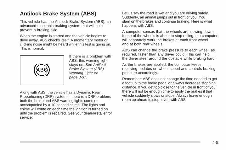
Antilock Brake System (ABS)This vehicle has the Antilock Brake System (ABS), anadvanced electronic braking system that will helpprevent a braking skid.
When the engine is started and the vehicle begins todrive away, ABS checks itself. A momentary motor orclicking noise might be heard while this test is going on.This is normal.
If there is a problem withABS, this warning lightstays on. See AntilockBrake System (ABS)Warning Light onpage 3-37.
Along with ABS, the vehicle has a Dynamic RearProportioning (DRP) system. If there is a DRP problem,both the brake and ABS warning lights come onaccompanied by a 10-second chime. The lights andchime will come on each time the ignition is turned onuntil the problem is repaired. See your dealer/retailer forservice.
Let us say the road is wet and you are driving safely.Suddenly, an animal jumps out in front of you. Youslam on the brakes and continue braking. Here is whathappens with ABS:
A computer senses that the wheels are slowing down.If one of the wheels is about to stop rolling, the computerwill separately work the brakes at each front wheeland at both rear wheels.
ABS can change the brake pressure to each wheel, asrequired, faster than any driver could. This can helpthe driver steer around the obstacle while braking hard.
As the brakes are applied, the computer keepsreceiving updates on wheel speed and controls brakingpressure accordingly.
Remember: ABS does not change the time needed to geta foot up to the brake pedal or always decrease stoppingdistance. If you get too close to the vehicle in front of you,there will not be enough time to apply the brakes if thatvehicle suddenly slows or stops. Always leave enoughroom up ahead to stop, even with ABS.
4-5

Using ABSDo not pump the brakes. Just hold the brake pedaldown firmly and let antilock work. The brakes mightvibrate or some noise might be heard, but this is normal.
Braking in EmergenciesABS allows the driver to steer and brake at the sametime. In many emergencies, steering can help more thaneven the very best braking.
Brake AssistThis vehicle has a Brake Assist feature designed toassist the driver in stopping or decreasing vehicle speedin emergency driving conditions. This feature uses thestability system hydraulic brake control module tosupplement the power brake system under conditionswhere the driver has quickly and forcefully applied thebrake pedal in an attempt to quickly stop or slow downthe vehicle. The stability system hydraulic brake controlmodule increases brake pressure at each corner of thevehicle until the ABS activates. Minor brake pedalpulsations or pedal movement during this time is normaland the driver should continue to apply the brake pedalas the driving situation dictates The Brake Assist featurewill automatically disengage when the brake pedal isreleased or brake pedal pressure is quickly decreased.
StabiliTrak® SystemThe vehicle has the StabiliTrak system which combinesantilock brake, traction and stability control systems andhelps the driver maintain directional control of the vehiclein most driving conditions.
Traction control activates when the controller senseswheel spin. StabiliTrak will selectively apply the brakesand reduce engine torque to help regain traction.
Stability control activates when the controller senses adiscrepancy between the intended path and the directionthe vehicle is travelling. StabiliTrak selectively appliesbraking pressure at any one of the vehicle’s brakes tohelp guide the vehicle in the intended direction.
When you first start the vehicle and begin to drive away,the system performs several diagnostic checks to insurethere are no problems. The system may be heard or feltwhile it is working. This is normal and does not meanthere is a problem with the vehicle. If driving conditionsdelay system initialization, the STABILITRAK NOTREADY message may be displayed on the DriverInformation Center (DIC). If this is the case, thevehicle does not need servicing.
For more information on the stability messages, seeDIC Warnings and Messages on page 3-51.
4-6
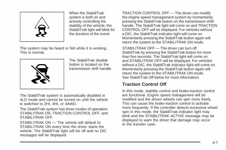
When the StabiliTraksystem is both on andactively controlling thestability of the vehicle, theStabiliTrak light will blink forthe duration of the event.
The system may be heard or felt while it is working.This is normal.
The StabiliTrak disablebutton is located on thetransmission shift handle.
The StabiliTrak system is automatically disabled in4LO mode and cannot be turned on until the vehicleis switched to 2HI, 4HI, or 4AWD.The StabiliTrak system has three modes of operation:STABILITRAK ON, TRACTION CONTROL OFF, andSTABILITRAK OFF.STABILITRAK ON — The vehicle will default toSTABILITRAK ON every time the driver starts thevehicle. The StabiliTrak light will be off and no DICmessages will be displayed.
TRACTION CONTROL OFF — The driver can modifythe engine speed management system by momentarilypressing the StabiliTrak button on the transmission shifthandle. The StabiliTrak light will come on and TRACTIONCONTROL OFF will be displayed. For vehicles withouta DIC, the StabiliTrak indicator light will come on.Momentarily pressing the StabiliTrak button again willreturn the system to the STABILITRAK ON mode.
STABILITRAK OFF — The driver can turn offStabiliTrak by pressing the StabiliTrak button for morethan five seconds. The StabiliTrak light will come onand STABILITRAK OFF will be displayed. For vehicleswithout a DIC, the StabiliTrak indicator light will come on.Momentarily pressing the StabiliTrak button again willreturn the system to the STABILITRAK ON mode.See StabiliTrak Off below for more information.
Traction Control OffIn this mode, stability control and brake-traction controlare functional. Engine speed management will bemodified and the driven wheels can spin more freely.This can cause the brake-traction control to activatemore frequently. If the controller detects excessive wheelspin in this mode, the StabiliTrak indicator light mayblink and the STABILITRAK ACTIVE message may bedisplayed to warn the driver that damage may occurto the transfer case.
4-7
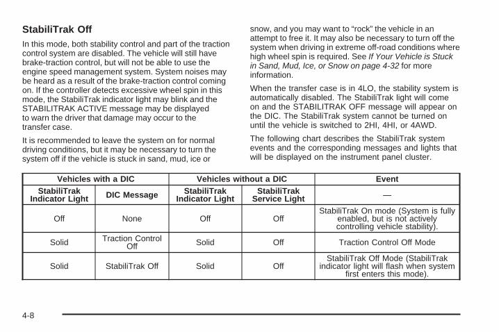
StabiliTrak OffIn this mode, both stability control and part of the tractioncontrol system are disabled. The vehicle will still havebrake-traction control, but will not be able to use theengine speed management system. System noises maybe heard as a result of the brake-traction control comingon. If the controller detects excessive wheel spin in thismode, the StabiliTrak indicator light may blink and theSTABILITRAK ACTIVE message may be displayedto warn the driver that damage may occur to thetransfer case.
It is recommended to leave the system on for normaldriving conditions, but it may be necessary to turn thesystem off if the vehicle is stuck in sand, mud, ice or
snow, and you may want to “rock” the vehicle in anattempt to free it. It may also be necessary to turn off thesystem when driving in extreme off-road conditions wherehigh wheel spin is required. See If Your Vehicle is Stuckin Sand, Mud, Ice, or Snow on page 4-32 for moreinformation.
When the transfer case is in 4LO, the stability system isautomatically disabled. The StabiliTrak light will comeon and the STABILITRAK OFF message will appear onthe DIC. The StabiliTrak system cannot be turned onuntil the vehicle is switched to 2HI, 4HI, or 4AWD.
The following chart describes the StabiliTrak systemevents and the corresponding messages and lights thatwill be displayed on the instrument panel cluster.
Vehicles with a DIC Vehicles without a DIC EventStabiliTrak
Indicator Light DIC Message StabiliTrakIndicator Light
StabiliTrakService Light —
Off None Off OffStabiliTrak On mode (System is fully
enabled, but is not activelycontrolling vehicle stability).
Solid Traction ControlOff Solid Off Traction Control Off Mode
Solid StabiliTrak Off Solid OffStabiliTrak Off Mode (StabiliTrak
indicator light will flash when systemfirst enters this mode).
4-8

Vehicles with a DIC Vehicles without a DIC Event
Blinking StabiliTrak Active Blinking OffStabiliTrak system activates usingengine speed management, brake
traction control, and/or stabilitycontrol.
Solid ServiceStabiliTrak Solid Solid StabiliTrak system is disabled due to
a system fault.
Solid StabiliTrak NotReady Solid Off StabiliTrak system is disabled due to
a failure to initialize.
Notice: If the StabiliTrak® light comes on due toheavy braking and/or because the traction controlsystem has been continuously active, do not allowthe wheel(s) of one axle to spin excessively. Thiscould lead to damage to the transfer case and costlyrepairs not covered by the vehicle warranty.
Notice: If the wheel(s) of one axle is allowed to spinexcessively while the StabiliTrak, ABS and brakewarning lights and any relevant DIC messages aredisplayed, the transfer case could be damaged. Therepairs would not be covered by the vehicle warranty.Reduce engine power and do not spin the wheel(s)excessively while these lights and messages aredisplayed.
StabiliTrak may activate on dry or rough roads or underconditions such as heavy acceleration while turningor abrupt upshifts/downshifts of the transmission.When this happens, a reduction in acceleration maybe noticed, or a noise or vibration may be heard.This is normal.If cruise control is being used when the system activates,the StabiliTrak light will flash and cruise control willautomatically disengage. Cruise control may bereengaged when road conditions allow. See CruiseControl on page 3-10.StabiliTrak will turn off automatically if a problem isdetected in the system. The StabiliTrak light will comeon and SERVICE STABILITRAK will be displayed onthe DIC. For vehicles without a DIC, the StabiliTraklight and the StabiliTrak service light will both come on.
4-9
If the SERVICE STABILITRAK message (or StabiliTrakservice light) does not clear itself after restarting thevehicle, see your dealer/retailer for service.
Adding non-GM accessories can affect the vehicle’sperformance. See Accessories and Modifications onpage 5-3 for more information.
Locking Rear AxleVehicles with a locking rear axle can give more tractionon snow, mud, ice, sand or gravel. It works like astandard axle most of the time, but when traction is low,this feature will allow the rear wheel with the mosttraction to move the vehicle.
All-Wheel Drive (AWD) SystemWith this feature, engine power is sent to all four wheelsat all times. This is like four-wheel drive, but there isno separate lever or switch to engage or disengage thefront axle. It is fully automatic, and adjusts itself asneeded for road conditions.
Steering
Power SteeringIf power steering assist is lost because the engine stopsor the system is not functioning, the vehicle can besteered but it will take more effort.
Steering TipsIt is important to take curves at a reasonable speed.
Traction in a curve depends on the condition of the tiresand the road surface, the angle at which the curve isbanked, and vehicle speed. While in a curve, speed isthe one factor that can be controlled.
If there is a need to reduce speed, do it before enteringthe curve, while the front wheels are straight.
Try to adjust the speed so you can drive through thecurve. Maintain a reasonable, steady speed. Wait toaccelerate until out of the curve, and then accelerategently into the straightaway.
4-10

Steering in EmergenciesThere are times when steering can be more effective thanbraking. For example, you come over a hill and find atruck stopped in your lane, or a car suddenly pulls outfrom nowhere, or a child darts out from between parkedcars and stops right in front of you. These problems canbe avoided by braking — if you can stop in time. Butsometimes you cannot stop in time because there is noroom. That is the time for evasive action — steeringaround the problem.
The vehicle can perform very well in emergencies likethese. First apply the brakes. See Braking on page 4-4.It is better to remove as much speed as possible from acollision. Then steer around the problem, to the left orright depending on the space available.
An emergency like this requires close attention anda quick decision. If holding the steering wheel at therecommended 9 and 3 o’clock positions, it can be turneda full 180 degrees very quickly without removing eitherhand. But you have to act fast, steer quickly, and just asquickly straighten the wheel once you have avoided theobject.
The fact that such emergency situations are alwayspossible is a good reason to practice defensive drivingat all times and wear safety belts properly.
4-11
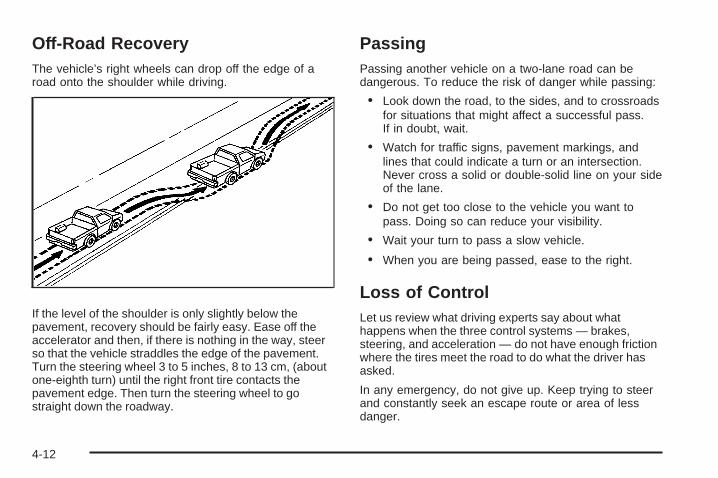
Off-Road RecoveryThe vehicle’s right wheels can drop off the edge of aroad onto the shoulder while driving.
If the level of the shoulder is only slightly below thepavement, recovery should be fairly easy. Ease off theaccelerator and then, if there is nothing in the way, steerso that the vehicle straddles the edge of the pavement.Turn the steering wheel 3 to 5 inches, 8 to 13 cm, (aboutone-eighth turn) until the right front tire contacts thepavement edge. Then turn the steering wheel to gostraight down the roadway.
PassingPassing another vehicle on a two-lane road can bedangerous. To reduce the risk of danger while passing:
• Look down the road, to the sides, and to crossroadsfor situations that might affect a successful pass.If in doubt, wait.
• Watch for traffic signs, pavement markings, andlines that could indicate a turn or an intersection.Never cross a solid or double-solid line on your sideof the lane.
• Do not get too close to the vehicle you want topass. Doing so can reduce your visibility.
• Wait your turn to pass a slow vehicle.
• When you are being passed, ease to the right.
Loss of ControlLet us review what driving experts say about whathappens when the three control systems — brakes,steering, and acceleration — do not have enough frictionwhere the tires meet the road to do what the driver hasasked.
In any emergency, do not give up. Keep trying to steerand constantly seek an escape route or area of lessdanger.
4-12

SkiddingIn a skid, a driver can lose control of the vehicle.Defensive drivers avoid most skids by taking reasonablecare suited to existing conditions, and by not overdrivingthose conditions. But skids are always possible.
The three types of skids correspond to the vehicle’sthree control systems. In the braking skid, the wheels arenot rolling. In the steering or cornering skid, too muchspeed or steering in a curve causes tires to slip and losecornering force. And in the acceleration skid, too muchthrottle causes the driving wheels to spin.
If the vehicle starts to slide, ease your foot off theaccelerator pedal and quickly steer the way you wantthe vehicle to go. If you start steering quickly enough,the vehicle may straighten out. Always be ready fora second skid if it occurs.
Of course, traction is reduced when water, snow, ice,gravel, or other material is on the road. For safety, slowdown and adjust your driving to these conditions. It isimportant to slow down on slippery surfaces becausestopping distance is longer and vehicle control morelimited.
While driving on a surface with reduced traction, tryyour best to avoid sudden steering, acceleration, orbraking, including reducing vehicle speed by shifting toa lower gear. Any sudden changes could cause the tiresto slide. You might not realize the surface is slipperyuntil the vehicle is skidding. Learn to recognize warningclues — such as enough water, ice, or packed snow onthe road to make a mirrored surface — and slow downwhen you have any doubt.
Remember: Any Antilock Brake System (ABS) helpsavoid only the braking skid.
4-13

Competitive DrivingSee your warranty book before using your vehicle forcompetitive driving. After reviewing your warranty book,please see the GM Performance Parts website or catalogfor parts and equipment required for competitive driving.
Notice: If you use your vehicle for competitivedriving, the engine may use more oil than it wouldwith normal use. Low oil levels can damage theengine. Be sure to check the oil level often duringcompetitive driving and keep the level at or near theupper mark that shows the proper operating rangeon the engine oil dipstick. For information on how toadd oil, see Engine Oil on page 5-18.
Off-Road DrivingVehicles with four-wheel drive can be used for off-roaddriving. Vehicles without four-wheel drive should notbe driven off-road except on a level, solid surface.
The airbag system is designed to work properly undera wide range of conditions, including off-road usage.Always wear your safety belt and observe safe drivingspeeds, especially on rough terrain.
Drinking and driving can be very dangerous on any roadand this is certainly true for off-road driving. At the verytime you need special alertness and driving skills, yourreflexes, perceptions, and judgment can be affectedby even a small amount of alcohol. You could have aserious — or even fatal — accident if you drink anddrive or ride with a driver who has been drinking.
4-14
Off-roading can be great fun but has some definitehazards. The greatest of these is the terrain itself. Whenoff-road driving, traffic lanes are not marked, curves arenot banked, and there are no road signs. Surfaces can beslippery, rough, uphill, or downhill.
Avoid sharp turns and abrupt maneuvers. Failure tooperate the vehicle correctly off-road could result in lossof vehicle control or vehicle rollover.
Off-roading involves some new skills. That is why it isvery important that you read these driving tips andsuggestions to help make off-road driving safer andmore enjoyable.
Before You Go Off-Roading• Have all necessary maintenance and service
work done.
• Make sure there is enough fuel, that fluid levels arewhere they should be, and that the spare tire, if thevehicle has one, is fully inflated.
• Be sure to read all the information aboutfour-wheel-drive vehicles in this manual.
• Make sure all underbody shields, if the vehicle hasthem, are properly attached.
• Know the local laws that apply to off-roading whereyou will be driving or check with law enforcementpeople in the area.
• Be sure to get the necessary permission if you willbe on private land.
4-15

Loading Your Vehicle for Off-RoadDriving
{CAUTION:
• Cargo on the load floor piled higher than theseatbacks can be thrown forward during asudden stop. You or your passengers couldbe injured. Keep cargo below the top of theseatbacks.
• Unsecured cargo on the load floor can betossed about when driving over rough terrain.You or your passengers can be struck byflying objects. Secure the cargo properly.
CAUTION: (Continued)
CAUTION: (Continued)
• Heavy loads on the roof raise the vehicle’scenter of gravity, making it more likely to rollover. You can be seriously or fatally injured ifthe vehicle rolls over. Put heavy loads insidethe cargo area, not on the roof. Keep cargo inthe cargo area as far forward and low aspossible.
There are some important things to remember abouthow to load your vehicle.
• The heaviest things should be on the floor, forwardof the rear axle. Put heavier items as far forwardas you can.
• Be sure the load is properly secured, so things arenot tossed around.
You will find other important information under Loadingthe Vehicle on page 4-33 and Tires on page 5-58.
4-16

Environmental ConcernsOff-road driving can provide wholesome and satisfyingrecreation. However, it also raises environmentalconcerns. We recognize these concerns and urge everyoff-roader to follow these basic rules for protecting theenvironment:
• Always use established trails, roads, and areas thathave been specially set aside for public off-roadrecreational driving and obey all posted regulations.
• Avoid any driving practice that could damage shrubs,flowers, trees, or grasses or disturb wildlife. Thisincludes wheel-spinning, breaking down trees, orunnecessary driving through streams or over softground.
• Always carry a litter bag and make sure all refuse isremoved from any campsite before leaving.
• Take extreme care with open fires (where permitted),camp stoves, and lanterns.
• Never park your vehicle over dry grass or othercombustible materials that could catch fire from theheat of the vehicle’s exhaust system.
Traveling to Remote AreasIt makes sense to plan your trip, especially when goingto a remote area. Know the terrain and plan your route.Get accurate maps of trails and terrain. Check to see ifthere are any blocked or closed roads.
It is also a good idea to travel with at least one othervehicle in case something happens to one of them.
For vehicles with a winch, be sure to read the winchinstructions. In a remote area, a winch can be handy ifyou get stuck but you will want to know how to useit properly.
Getting Familiar with Off-Road DrivingIt is a good idea to practice in an area that is safeand close to home before you go into the wilderness.Off-roading requires some new and different skills.
Tune your senses to different kinds of signals. Your eyesneed to constantly sweep the terrain for unexpectedobstacles. Your ears need to listen for unusual tire orengine sounds. Use your arms, hands, feet, and bodyto respond to vibrations and vehicle bounce.
4-17

Controlling the vehicle is the key to successful off-roaddriving. One of the best ways to control the vehicleis to control the speed. At higher speeds:
• You approach things faster and have less time toreact.
• There is less time to scan the terrain for obstacles.
• The vehicle has more bounce when driving overobstacles.
• More braking distance is needed, especially on anunpaved surface.
{CAUTION:
When you are driving off-road, bouncing and quickchanges in direction can easily throw you out ofposition. This could cause you to lose control andcrash. So, whether you are driving on or off theroad, you and your passengers should wearsafety belts.
Scanning the TerrainOff-road driving can take you over many different kindsof terrain. Be familiar with the terrain and its manydifferent features.
Surface Conditions: Off-roading surfaces can behard-packed dirt, gravel, rocks, grass, sand, mud, snow,or ice. Each of these surfaces affects the vehicle’ssteering, acceleration, and braking in different ways.Depending on the surface, slipping, sliding, wheelspinning, delayed acceleration, poor traction, and longerbraking distances can occur.
Surface Obstacles: Unseen or hidden obstacles canbe hazardous. A rock, log, hole, rut, or bump can startleyou if you are not prepared for them. Often theseobstacles are hidden by grass, bushes, snow, or eventhe rise and fall of the terrain itself.
Some things to consider:
• Is the path ahead clear?
• Will the surface texture change abruptly up ahead?
• Does the travel take you uphill or downhill?
• Will you have to stop suddenly or change directionquickly?
4-18
When driving over obstacles or rough terrain, keep a firmgrip on the steering wheel. Ruts, troughs, or other surfacefeatures can jerk the wheel out of your hands.
When driving over bumps, rocks, or other obstacles, thewheels can leave the ground. If this happens, evenwith one or two wheels, you cannot control the vehicleas well or at all.
Because you will be on an unpaved surface, it isespecially important to avoid sudden acceleration,sudden turns, or sudden braking.
Off-roading requires a different kind of alertness fromdriving on paved roads and highways. There are no roadsigns, posted speed limits, or signal lights. Use goodjudgment about what is safe and what is not.
Driving on HillsOff-road driving often takes you up, down, or across ahill. Driving safely on hills requires good judgmentand an understanding of what the vehicle can andcannot do. There are some hills that simply cannot bedriven, no matter how well built the vehicle.
{CAUTION:
Many hills are simply too steep for any vehicle.If you drive up them, you will stall. If you drivedown them, you cannot control your speed. If youdrive across them, you will roll over. You could beseriously injured or killed. If you have any doubtabout the steepness, do not drive the hill.
4-19
Approaching a HillWhen you approach a hill, decide if it is too steep toclimb, descend, or cross. Steepness can be hardto judge. On a very small hill, for example, there maybe a smooth, constant incline with only a small changein elevation where you can easily see all the way tothe top. On a large hill, the incline may get steeper asyou near the top, but you might not see this because thecrest of the hill is hidden by bushes, grass, or shrubs.
Consider this as you approach a hill:
• Is there a constant incline, or does the hill getsharply steeper in places?
• Is there good traction on the hillside, or will thesurface cause tire slipping?
• Is there a straight path up or down the hill so youwill not have to make turning maneuvers?
• Are there obstructions on the hill that can block yourpath, such as boulders, trees, logs, or ruts?
• What is beyond the hill? Is there a cliff, anembankment, a drop-off, a fence? Get out and walkthe hill if you do not know. It is the smart way tofind out.
• Is the hill simply too rough? Steep hills often haveruts, gullies, troughs, and exposed rocks becausethey are more susceptible to the effects of erosion.
Driving UphillOnce you decide it is safe to drive up the hill:
• Use a low gear and get a firm grip on the steeringwheel.
• Get a smooth start up the hill and try to maintainspeed. Not using more power than needed canavoid spinning the wheels or sliding.
{CAUTION:
Turning or driving across steep hills can bedangerous. You could lose traction, slidesideways, and possibly roll over. You could beseriously injured or killed. When driving up hills,always try to go straight up.
• Try to drive straight up the hill if at all possible.If the path twists and turns, you might want tofind another route.
• Ease up on the speed as you approach the top ofthe hill.
4-20

• Attach a flag to the vehicle to be more visible toapproaching traffic on trails or hills.
• Sound the horn as you approach the top of the hillto let opposing traffic know you are there.
• Use headlamps even during the day to make thevehicle more visible to oncoming traffic.
{CAUTION:
Driving to the top (crest) of a hill at full speed cancause an accident. There could be a drop-off,embankment, cliff, or even another vehicle. Youcould be seriously injured or killed. As you nearthe top of a hill, slow down and stay alert.
If the vehicle stalls, or is about to stall, and you cannotmake it up the hill:
• Push the brake pedal to stop the vehicle and keepit from rolling backwards and apply the parkingbrake.
• If the engine is still running, shift the transmissionto R (Reverse), release the parking brake, andslowly back down the hill in R (Reverse).
• If the engine has stopped running, you need torestart it. With the brake pedal pressed and theparking brake still applied, shift the transmissionto P (Park) and restart the engine. Then, shiftto R (Reverse), release the parking brake, andslowly back down the hill as straight as possiblein R (Reverse).
• While backing down the hill, put your left hand on thesteering wheel at the 12 o’clock position so you cantell if the wheels are straight and can maneuver asyou back down. It is best to back down the hill withthe wheels straight rather than in the left or rightdirection. Turning the wheel too far to the left orright will increase the possibility of a rollover.
4-21

Things not to do if the vehicle stalls, or is about to stall,when going up a hill:
• Never attempt to prevent a stall by shifting intoN (Neutral) to rev-up the engine and regain forwardmomentum. This will not work. The vehicle can rollbackward very quickly and could go out of control.
• Never try to turn around if about to stall when goingup a hill. If the hill is steep enough to stall the vehicle,it is steep enough to cause it to roll over. If youcannot make it up the hill, back straight down the hill.
If, after stalling, you try to back down the hill and decideyou just cannot do it, set the parking brake, put yourtransmission in P (Park), and turn off the engine. Leavethe vehicle and go get some help. Exit on the uphill sideand stay clear of the path the vehicle would take if it rolleddownhill. Do not shift the transfer case to Neutral whenyou leave the vehicle. Leave it in some gear.
{CAUTION:
Shifting the transfer case to Neutral can cause yourvehicle to roll even if the transmission is in P (Park).This is because the Neutral position on the transfercase overrides the transmission. You or someoneelse could be injured. If you are going to leaveyour vehicle, set the parking brake and shift thetransmission to P (Park). But do not shift thetransfer case to Neutral.
Driving DownhillWhen off-roading takes you downhill, consider:
• How steep is the downhill? Will I be able to maintainvehicle control?
• What is the surface like? Smooth? Rough?Slippery? Hard-packed dirt? Gravel?
• Are there hidden surface obstacles? Ruts? Logs?Boulders?
• What is at the bottom of the hill? Is there a hiddencreek bank or even a river bottom with largerocks?
4-22

If you decide you can go down a hill safely, try to keepthe vehicle headed straight down. Use a low gearso engine drag can help the brakes so they do nothave to do all the work. Descend slowly, keeping thevehicle under control at all times.
{CAUTION:
Heavy braking when going down a hill can causeyour brakes to overheat and fade. This could causeloss of control and a serious accident. Apply thebrakes lightly when descending a hill and use a lowgear to keep vehicle speed under control.
Things not to do when driving down a hill:
• When driving downhill, avoid turns that take youacross the incline of the hill. A hill that is not toosteep to drive down might be too steep to driveacross. The vehicle could roll over.
• Never go downhill with the transmission inN (Neutral), called free-wheeling. The brakes willhave to do all the work and could overheat and fade.
Vehicles are much more likely to stall when going uphill,but if it happens when going downhill:
1. Stop the vehicle by applying the regular brakes andapply the parking brake.
2. Shift to P (Park) and, while still braking, restart theengine.
3. Shift back to a low gear, release the parking brake,and drive straight down.
4. If the engine will not start, get out and get help.
4-23
Driving Across an InclineAn off-road trail will probably go across the incline of ahill. To decide whether to try to drive across theincline, consider the following:
{CAUTION:
Driving across an incline that is too steep willmake your vehicle roll over. You could beseriously injured or killed. If you have any doubtabout the steepness of the incline, do not driveacross it. Find another route instead.
• A hill that can be driven straight up or downmight be too steep to drive across. When goingstraight up or down a hill, the length of the wheelbase — the distance from the front wheels to the rearwheels — reduces the likelihood the vehicle willtumble end over end. But when driving across anincline, the narrower track width — the distancebetween the left and right wheels — might notprevent the vehicle from tilting and rolling over.Driving across an incline puts more weight on thedownhill wheels which could cause a downhill slideor a rollover.
• Surface conditions can be a problem. Loose gravel,muddy spots, or even wet grass can cause thetires to slip sideways, downhill. If the vehicle slipssideways, it can hit something that will trip it — arock, a rut, etc. — and roll over.
• Hidden obstacles can make the steepness of theincline even worse. If you drive across a rock with theuphill wheels, or if the downhill wheels drop into a rutor depression, the vehicle can tilt even more.
For these reasons, carefully consider whether to try todrive across an incline. Just because the trail goesacross the incline does not mean you have to drive it.The last vehicle to try it might have rolled over.
If you feel the vehicle starting to slide sideways, turndownhill. This should help straighten out the vehicleand prevent the side slipping. The best way to preventthis is to “walk the course” first, so you know whatthe surface is like before driving it.
4-24
Stalling on an Incline
{CAUTION:
Getting out on the downhill (low) side of a vehiclestopped across an incline is dangerous. If thevehicle rolls over, you could be crushed or killed.Always get out on the uphill (high) side of thevehicle and stay well clear of the rollover path.
If the vehicle stalls when crossing an incline, be sure you,and any passengers, get out on the uphill side, even if thedoor there is harder to open. If you get out on the downhillside and the vehicle starts to roll over, you will be right inits path.
If you have to walk down the slope, stay out of the paththe vehicle will take if it does roll over.
Driving in Mud, Sand, Snow, or IceWhen you drive in mud, snow, or sand, the wheels do notget good traction. Acceleration is not as quick, turning ismore difficult, and braking distances are longer.
It is best to use a low gear when in mud — the deeperthe mud, the lower the gear. In really deep mud,keep the vehicle moving so it does not get stuck.
When driving on sand, wheel traction changes.On loosely packed sand, such as on beaches or sanddunes, the tires will tend to sink into the sand. Thisaffects steering, accelerating, and braking. Drive at areduced speed and avoid sharp turns or abruptmaneuvers.
Hard packed snow and ice offer the worst tire traction.On these surfaces, it is very easy to lose control.On wet ice, for example, the traction is so poor thatyou will have difficulty accelerating. And, if the vehicledoes get moving, poor steering and difficult braking cancause it to slide out of control.
{CAUTION:
Driving on frozen lakes, ponds, or rivers can bedangerous. Underwater springs, currents underthe ice, or sudden thaws can weaken the ice. Yourvehicle could fall through the ice and you and yourpassengers could drown. Drive your vehicle onsafe surfaces only.
4-25
Driving in Water
{CAUTION:
Driving through rushing water can be dangerous.Deep water can sweep your vehicle downstreamand you and your passengers could drown. If it isonly shallow water, it can still wash away theground from under your tires, and you could losetraction and roll the vehicle over. Do not drivethrough rushing water.
Heavy rain can mean flash flooding, and flood watersdemand extreme caution.
Find out how deep the water is before driving through it.Do not try it if it is deep enough to cover the wheel hubs,axles, or exhaust pipe — you probably will not getthrough. Deep water can damage the axle and othervehicle parts.
If the water is not too deep, drive slowly through it. Atfaster speeds, water splashes on the ignition system andthe vehicle can stall. Stalling can also occur if you get thetailpipe under water. If the tailpipe is under water, you willnever be able to start the engine. When going throughwater, remember that when the brakes get wet, it mighttake longer to stop. See Driving in Rain and on WetRoads on page 4-27.
After Off-Road DrivingRemove any brush or debris that has collected onthe underbody, chassis, or under the hood. Theseaccumulations can be a fire hazard.
After operation in mud or sand, have the brake liningscleaned and checked. These substances can causeglazing and uneven braking. Check the body structure,steering, suspension, wheels, tires, and exhaust systemfor damage and check the fuel lines and cooling systemfor any leakage.
The vehicle requires more frequent service due tooff-road use. Refer to the Maintenance Schedule foradditional information.
4-26
Driving at NightNight driving is more dangerous than day driving becausesome drivers are likely to be impaired — by alcohol ordrugs, with night vision problems, or by fatigue.Night driving tips include:
• Drive defensively.
• Do not drink and drive.
• Reduce headlamp glare by adjusting the insiderearview mirror.
• Slow down and keep more space between you andother vehicles because headlamps can only light upso much road ahead.
• Watch for animals.
• When tired, pull off the road.
• Do not wear sunglasses.
• Avoid staring directly into approaching headlamps.
• Keep the windshield and all glass on your vehicleclean — inside and out.
• Keep your eyes moving, especially during turns orcurves.
No one can see as well at night as in the daytime.But, as we get older, these differences increase.A 50-year-old driver might need at least twice as muchlight to see the same thing at night as a 20-year-old.
Driving in Rain and on Wet RoadsRain and wet roads can reduce vehicle tractionand affect your ability to stop and accelerate. Alwaysdrive slower in these types of driving conditionsand avoid driving through large puddles anddeep-standing or flowing water.
{CAUTION:
Wet brakes can cause crashes. They might notwork as well in a quick stop and could cause pullingto one side. You could lose control of the vehicle.
After driving through a large puddle of water or acar/vehicle wash, lightly apply the brake pedal untilthe brakes work normally.
Flowing or rushing water creates strong forces.Driving through flowing water could cause yourvehicle to be carried away. If this happens, you andother vehicle occupants could drown. Do not ignorepolice warnings and be very cautious about trying todrive through flowing water.
4-27

HydroplaningHydroplaning is dangerous. Water can build up underyour vehicle’s tires so they actually ride on the water. Thiscan happen if the road is wet enough and you are goingfast enough. When your vehicle is hydroplaning, it haslittle or no contact with the road.
There is no hard and fast rule about hydroplaning.The best advice is to slow down when the road is wet.
Other Rainy Weather TipsBesides slowing down, other wet weather driving tipsinclude:
• Allow extra following distance.
• Pass with caution.
• Keep windshield wiping equipment in good shape.
• Keep the windshield washer fluid reservoir filled.
• Have good tires with proper tread depth. See Tireson page 5-58.
• Turn off cruise control.
Before Leaving on a Long TripTo prepare your vehicle for a long trip, consider havingit serviced by your dealer/retailer before departing.Things to check on your own include:• Windshield Washer Fluid: Reservoir full? Windows
clean — inside and outside?• Wiper Blades: In good shape?
• Fuel, Engine Oil, Other Fluids: All levels checked?• Lamps: Do they all work and are lenses clean?
• Tires: Are treads good? Are tires inflated torecommended pressure?
• Weather and Maps: Safe to travel? Haveup-to-date maps?
Highway HypnosisAlways be alert and pay attention to your surroundingswhile driving. If you become tired or sleepy, find a safeplace to park your vehicle and rest.
Other driving tips include:• Keep the vehicle well ventilated.• Keep interior temperature cool.• Keep your eyes moving — scan the road ahead
and to the sides.• Check the rearview mirror and vehicle instruments
often.
4-28
Hill and Mountain RoadsDriving on steep hills or through mountains is differentthan driving on flat or rolling terrain. Tips for drivingin these conditions include:
• Keep the vehicle serviced and in good shape.
• Check all fluid levels and brakes, tires, coolingsystem, and transmission.
• Going down steep or long hills, shift to alower gear.
{CAUTION:
If you do not shift down, the brakes could get sohot that they would not work well. You would thenhave poor braking or even none going down a hill.You could crash. Shift down to let the engineassist the brakes on a steep downhill slope.
{CAUTION:
Coasting downhill in N (Neutral) or with the ignitionoff is dangerous. The brakes will have to do all thework of slowing down and they could get so hot thatthey would not work well. You would then have poorbraking or even none going down a hill. You couldcrash. Always have the engine running and thevehicle in gear when going downhill.
• Stay in your own lane. Do not swing wide or cutacross the center of the road. Drive at speeds thatlet you stay in your own lane.
• Top of hills: Be alert — something could be inyour lane (stalled car, accident).
• Pay attention to special road signs (falling rocksarea, winding roads, long grades, passing orno-passing zones) and take appropriate action.
See Off-Road Driving on page 4-14 for informationabout driving off-road.
4-29
Winter Driving
Driving on Snow or IceDrive carefully when there is snow or ice between thetires and the road, creating less traction or grip. Wet icecan occur at about 32°F (0°C) when freezing rain beginsto fall, resulting in even less traction. Avoid driving on wetice or in freezing rain until roads can be treated with saltor sand.
Drive with caution, whatever the condition. Accelerategently so traction is not lost. Accelerating too quicklycauses the wheels to spin and makes the surface underthe tires slick, so there is even less traction.
Try not to break the fragile traction. If you accelerate toofast, the drive wheels will spin and polish the surfaceunder the tires even more.
The Antilock Brake System (ABS) on page 4-5 improvesvehicle stability during hard stops on a slippery roads, butapply the brakes sooner than when on dry pavement.
Allow greater following distance on any slippery roadand watch for slippery spots. Icy patches can occur onotherwise clear roads in shaded areas. The surfaceof a curve or an overpass can remain icy when thesurrounding roads are clear. Avoid sudden steeringmaneuvers and braking while on ice.
Turn off cruise control, if equipped, on slippery surfaces.
Blizzard ConditionsBeing stuck in snow can be in a serious situation. Staywith the vehicle unless there is help nearby. If possible,use the Roadside Assistance Program on page 7-7.To get help and keep everyone in the vehicle safe:
• Turn on the Hazard Warning Flashers on page 3-6.
• Tie a red cloth to an outside mirror.
{CAUTION:
Snow can trap engine exhaust under the vehicle.This may cause exhaust gases to get inside.Engine exhaust contains carbon monoxide (CO)which cannot be seen or smelled. It can causeunconsciousness and even death.
If the vehicle is stuck in the snow:• Clear away snow from around the base of
your vehicle, especially any that is blockingthe exhaust pipe.
• Check again from time to time to be suresnow does not collect there.
CAUTION: (Continued)
4-30
CAUTION: (Continued)
• Open a window about two inches (5 cm) onthe side of the vehicle that is away from thewind to bring in fresh air.
• Fully open the air outlets on or under theinstrument panel.
• Adjust the Climate Control system to a settingthat circulates the air inside the vehicle andset the fan speed to the highest setting.See Climate Control System in the Index.
For more information about carbon monoxide, seeEngine Exhaust on page 2-38.
Snow can trap exhaust gases under your vehicle.This can cause deadly CO (carbon monoxide) gasto get inside. CO could overcome you and kill you.You cannot see it or smell it, so you might notknow it is in your vehicle. Clear away snow fromaround the base of your vehicle, especially anythat is blocking the exhaust.
Run the engine for short periods only as needed tokeep warm, but be careful.
To save fuel, run the engine for only short periods asneeded to warm the vehicle and then shut the engineoff and close the window most of the way to save heat.Repeat this until help arrives but only when you feelreally uncomfortable from the cold. Moving aboutto keep warm also helps.
If it takes some time for help to arrive, now and thenwhen you run the engine, push the accelerator pedalslightly so the engine runs faster than the idle speed.This keeps the battery charged to restart the vehicle andto signal for help with the headlamps. Do this as little aspossible to save fuel.
4-31

If Your Vehicle is Stuck in Sand,Mud, Ice, or SnowSlowly and cautiously spin the wheels to free thevehicle when stuck in sand, mud, ice, or snow. SeeRocking Your Vehicle to Get It Out on page 4-32.
If the vehicle has a traction system, it can often help tofree a stuck vehicle. Refer to the vehicle’s traction systemin the Index. If stuck too severely for the traction systemto free the vehicle, turn the traction system off and usethe rocking method.
{CAUTION:
If you let your vehicle’s tires spin at high speed,they can explode, and you or others could beinjured. The vehicle can overheat, causing anengine compartment fire or other damage. Spin thewheels as little as possible and avoid going above35 mph (55 km/h) as shown on the speedometer.
For information about using tire chains on the vehicle,see Tire Chains on page 5-81.
Rocking Your Vehicle to Get It OutTurn the steering wheel left and right to clear the areaaround the front wheels. For four-wheel-drive vehicles,shift into Four-Wheel High. For vehicles with StabiliTrak®,turn the traction control part of the system off. Shift backand forth between R (Reverse) and a forward gear,spinning the wheels as little as possible. To preventtransmission wear, wait until the wheels stop spinningbefore shifting gears. Release the accelerator pedal whileshifting, and press lightly on the accelerator pedal whenthe transmission is in gear. Slowly spinning the wheels inthe forward and reverse directions causes a rockingmotion that could free the vehicle. If that does not get thevehicle out after a few tries, it might need to be towed out.Recovery hooks can be used, if the vehicle has them.If the vehicle does need to be towed out, see TowingYour Vehicle on page 4-40.
Recovery Hooks
{CAUTION:
These hooks, when used, are under a lot of force.Always pull the vehicle straight out. Never pull onthe hooks at a sideways angle. The hooks couldbreak off and you or others could be injured fromthe chain or cable snapping back.
4-32
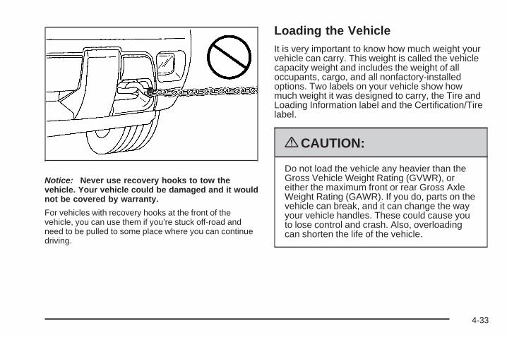
Notice: Never use recovery hooks to tow thevehicle. Your vehicle could be damaged and it wouldnot be covered by warranty.
For vehicles with recovery hooks at the front of thevehicle, you can use them if you’re stuck off-road andneed to be pulled to some place where you can continuedriving.
Loading the VehicleIt is very important to know how much weight yourvehicle can carry. This weight is called the vehiclecapacity weight and includes the weight of alloccupants, cargo, and all nonfactory-installedoptions. Two labels on your vehicle show howmuch weight it was designed to carry, the Tire andLoading Information label and the Certification/Tirelabel.
{CAUTION:
Do not load the vehicle any heavier than theGross Vehicle Weight Rating (GVWR), oreither the maximum front or rear Gross AxleWeight Rating (GAWR). If you do, parts on thevehicle can break, and it can change the wayyour vehicle handles. These could cause youto lose control and crash. Also, overloadingcan shorten the life of the vehicle.
4-33

Tire and Loading Information Label
A vehicle specific Tire and Loading Informationlabel is attached to the center pillar (B-pillar).With the driver’s door open, you will find thelabel attached below the door lock post (striker).
The Tire and Loading Information label shows thenumber of occupant seating positions (A), and themaximum vehicle capacity weight (B) in kilogramsand pounds.
The Tire and Loading Information label also showsthe size of the original equipment tires (C) and therecommended cold tire inflation pressures (D). Formore information on tires and inflation see Tires onpage 5-58 and Inflation - Tire Pressure onpage 5-65.
There is also important loading information on thevehicle Certification/Tire label. It tells you the GrossVehicle Weight Rating (GVWR) and the Gross AxleWeight Rating (GAWR) for the front and rear axle.See “Certification/Tire Label” later in this section.
Label Example
4-34
Steps for Determining Correct Load Limit1. Locate the statement “The combined weight
of occupants and cargo should never exceedXXX kg or XXX lbs” on your vehicle’s placard.
2. Determine the combined weight of the driverand passengers that will be riding in yourvehicle.
3. Subtract the combined weight of the driverand passengers from XXX kg or XXX lbs.
4. The resulting figure equals the availableamount of cargo and luggage load capacity.For example, if the “XXX” amount equals1400 lbs and there will be five 150 lbpassengers in your vehicle, the amount ofavailable cargo and luggage load capacity is650 lbs (1400 − 750 (5 x 150) = 650 lbs).
5. Determine the combined weight of luggageand cargo being loaded on the vehicle. Thatweight may not safely exceed the availablecargo and luggage load capacity calculatedin Step 4.
6. If your vehicle will be towing a trailer, the loadfrom your trailer will be transferred to yourvehicle. Consult this manual to determine howthis reduces the available cargo and luggageload capacity of your vehicle. See Towing aTrailer on page 4-48 for important informationon towing a trailer, towing safety rules andtrailering tips.
4-35
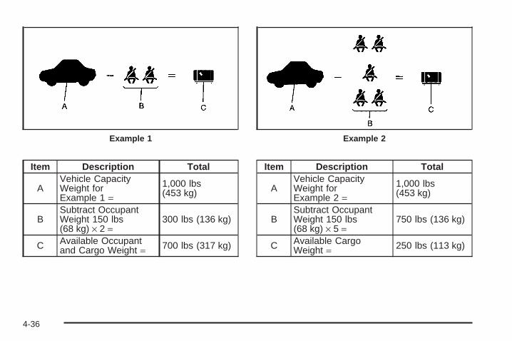
Item Description Total
AVehicle CapacityWeight forExample 1 =
1,000 lbs(453 kg)
BSubtract OccupantWeight 150 lbs(68 kg) × 2 =
300 lbs (136 kg)
C Available Occupantand Cargo Weight = 700 lbs (317 kg)
Item Description Total
AVehicle CapacityWeight forExample 2 =
1,000 lbs(453 kg)
BSubtract OccupantWeight 150 lbs(68 kg) × 5 =
750 lbs (136 kg)
C Available CargoWeight = 250 lbs (113 kg)
Example 1 Example 2
4-36

Item Description Total
AVehicle CapacityWeight forExample 3 =
1,000 lbs(453 kg)
BSubtract OccupantWeight 200 lbs(91 kg) × 5 =
1,000 lbs(453 kg)
C Available CargoWeight = 0 lbs (0 kg)
Refer to your vehicle’s Tire and LoadingInformation label for specific information aboutyour vehicle’s capacity weight and seatingpositions. The combined weight of the driver,passengers, and cargo should never exceed yourvehicle’s capacity weight.
Your vehicle may have an electronically controlledair suspension system that automatically keepsyour vehicle level as you load and unload yourvehicle. See Electronically Controlled AirSuspension System on page 4-47 for additionalinformation.Example 3
4-37

Certification/Tire Label
A vehicle specific Certification/Tire label is foundon the rear edge of the driver’s door. The labelshows the size of your vehicle’s original tires andthe inflation pressures needed to obtain the grossweight capacity of your vehicle. This is calledGross Vehicle Weight Rating (GVWR). The GVWRincludes the weight of the vehicle, all occupants,fuel, cargo, and trailer tongue weight, if pulling atrailer.
The Certification/Tire label also tells you themaximum weights for the front and rear axles,called Gross Axle Weight Rating (GAWR).
To find out the actual loads on your front and rearaxles, you need to go to a weigh station and weighyour vehicle. Your dealer can help you with this.Be sure to spread out your load equally on bothsides of the centerline.
Never exceed the GVWR for your vehicle, or theGAWR for either the front or rear axle.
And, if you do have a heavy load, you shouldspread it out.
Similar appearing vehicles may have differentGVWRs and capacity weights. Please note yourvehicle’s Certification/Tire label or consult yourdealer for additional details.
{CAUTION:
Do not load the vehicle any heavier than theGross Vehicle Weight Rating (GVWR), oreither the maximum front or rear Gross AxleWeight Rating (GAWR). If you do, parts on thevehicle can break, and it can change the wayyour vehicle handles. These could cause youto lose control and crash. Also, overloadingcan shorten the life of the vehicle.
4-38
Using heavier suspension components to getadded durability might not change your vehicle’sweight ratings. Ask your dealer to help youload your vehicle the right way.
Notice: Overloading your vehicle may causedamage. Repairs would not be covered by yourwarranty. Do not overload your vehicle.If you put things inside your vehicle — likesuitcases, tools, packages, or anything else — theywill go as fast as the vehicle goes. If you have tostop or turn quickly, or if there is a crash, they willkeep going.
{CAUTION:
Things you put inside your vehicle can strikeand injure people in a sudden stop or turn, orin a crash.
• Put things in the cargo area of yourvehicle. Try to spread the weight evenly.
• Never stack heavier things, likesuitcases, inside the vehicle so that someof them are above the tops of the seats.
CAUTION: (Continued)
CAUTION: (Continued)
• Do not leave an unsecured child restraintin your vehicle.
• When you carry something inside thevehicle, secure it whenever you can.
• Do not leave a seat folded down unlessyou need to.
There is also important loading information foroff-road driving in this manual. See “Loading YourVehicle for Off-Road Driving” under Off-RoadDriving on page 4-14.
Adding a Snow Plow or SimilarEquipmentYour vehicle was neither designed nor intended for asnow plow.
Notice: Adding a snow plow or similar equipmentto your vehicle can damage it, and the repairs wouldnot be covered by warranty. Do not install a snowplow or similar equipment on your vehicle.
4-39
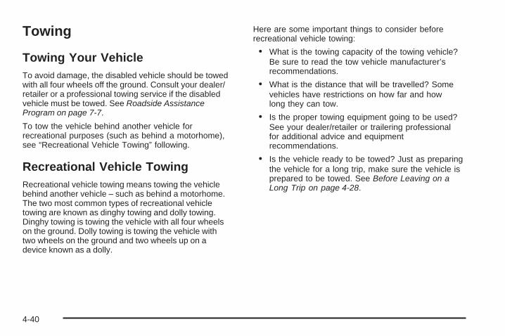
Towing
Towing Your VehicleTo avoid damage, the disabled vehicle should be towedwith all four wheels off the ground. Consult your dealer/retailer or a professional towing service if the disabledvehicle must be towed. See Roadside AssistanceProgram on page 7-7.
To tow the vehicle behind another vehicle forrecreational purposes (such as behind a motorhome),see “Recreational Vehicle Towing” following.
Recreational Vehicle TowingRecreational vehicle towing means towing the vehiclebehind another vehicle – such as behind a motorhome.The two most common types of recreational vehicletowing are known as dinghy towing and dolly towing.Dinghy towing is towing the vehicle with all four wheelson the ground. Dolly towing is towing the vehicle withtwo wheels on the ground and two wheels up on adevice known as a dolly.
Here are some important things to consider beforerecreational vehicle towing:
• What is the towing capacity of the towing vehicle?Be sure to read the tow vehicle manufacturer’srecommendations.
• What is the distance that will be travelled? Somevehicles have restrictions on how far and howlong they can tow.
• Is the proper towing equipment going to be used?See your dealer/retailer or trailering professionalfor additional advice and equipmentrecommendations.
• Is the vehicle ready to be towed? Just as preparingthe vehicle for a long trip, make sure the vehicle isprepared to be towed. See Before Leaving on aLong Trip on page 4-28.
4-40

All-Wheel-Drive Vehicles(TrailBlazer SS)
Notice: Towing an all-wheel-drive vehicle withall four wheels on the ground, or even withonly two of its wheels on the ground, willdamage drivetrain components. Do not tow anall-wheel-drive vehicle with any of its wheelson the ground.
The vehicle was not designed to be towed with anyof its wheels on the ground. If the vehicle must betowed, see “Towing Your Vehicle” earlier in thissection.
Dinghy TowingTwo-Wheel-Drive Vehicles
Notice: If the vehicle is towed with all four wheelson the ground, the drivetrain components couldbe damaged. The repairs would not be covered bythe vehicle warranty. Do not tow the vehicle with allfour wheels on the ground.
Two-wheel-drive vehicles should not be towedwith all four wheels on the ground. Two-wheel-drivetransmissions have no provisions for internal lubricationwhile being towed. To properly tow these vehicles, theyshould be placed on a flatbed truck or trailer.
4-41
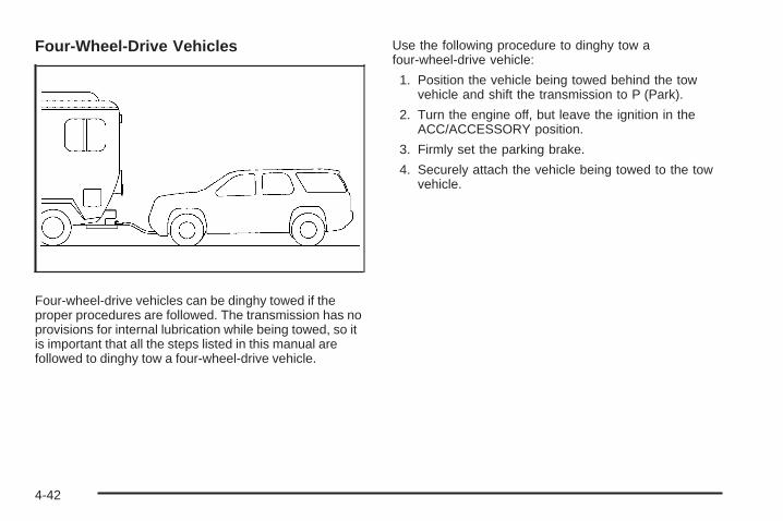
Four-Wheel-Drive Vehicles
Four-wheel-drive vehicles can be dinghy towed if theproper procedures are followed. The transmission has noprovisions for internal lubrication while being towed, so itis important that all the steps listed in this manual arefollowed to dinghy tow a four-wheel-drive vehicle.
Use the following procedure to dinghy tow afour-wheel-drive vehicle:
1. Position the vehicle being towed behind the towvehicle and shift the transmission to P (Park).
2. Turn the engine off, but leave the ignition in theACC/ACCESSORY position.
3. Firmly set the parking brake.
4. Securely attach the vehicle being towed to the towvehicle.
4-42

{CAUTION:
Shifting a four-wheel-drive vehicle’s transfer caseinto N (Neutral) can cause the vehicle to roll evenif the transmission is in P (Park). The driver orothers could be injured. Make sure the parkingbrake is firmly set before the transfer case isshifted to N (Neutral).
5. Shift the transfer case to Neutral. See “Shifting intoNeutral” under Four-Wheel Drive on page 2-30.
6. Release the parking brake only after the vehiclebeing towed is firmly attached to the towing vehicle.
7. Turn the ignition to LOCK/OFF and remove thekey — the steering wheel will still turn.
After towing, see “Shifting Out of Neutral” underFour-Wheel Drive on page 2-30.
Dolly Towing
Front Towing (Front Wheels Off theGround)
Two-Wheel-Drive Vehicles
Notice: If a two-wheel-drive vehicle is towed withthe rear wheels on the ground, the transmissioncould be damaged. The repairs would not becovered by the vehicle warranty. Never tow thevehicle with the rear wheels on the ground.
4-43
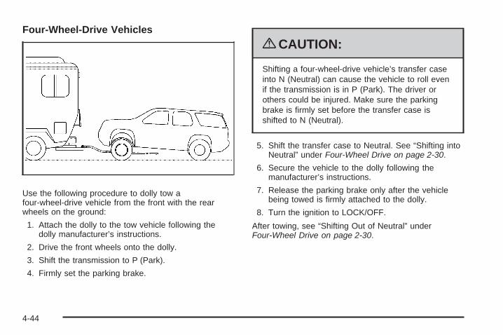
Four-Wheel-Drive Vehicles
Use the following procedure to dolly tow afour-wheel-drive vehicle from the front with the rearwheels on the ground:
1. Attach the dolly to the tow vehicle following thedolly manufacturer’s instructions.
2. Drive the front wheels onto the dolly.
3. Shift the transmission to P (Park).
4. Firmly set the parking brake.
{CAUTION:
Shifting a four-wheel-drive vehicle’s transfer caseinto N (Neutral) can cause the vehicle to roll evenif the transmission is in P (Park). The driver orothers could be injured. Make sure the parkingbrake is firmly set before the transfer case isshifted to N (Neutral).
5. Shift the transfer case to Neutral. See “Shifting intoNeutral” under Four-Wheel Drive on page 2-30.
6. Secure the vehicle to the dolly following themanufacturer’s instructions.
7. Release the parking brake only after the vehiclebeing towed is firmly attached to the dolly.
8. Turn the ignition to LOCK/OFF.
After towing, see “Shifting Out of Neutral” underFour-Wheel Drive on page 2-30.
4-44
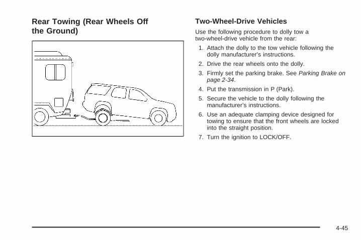
Rear Towing (Rear Wheels Offthe Ground)
Two-Wheel-Drive VehiclesUse the following procedure to dolly tow atwo-wheel-drive vehicle from the rear:
1. Attach the dolly to the tow vehicle following thedolly manufacturer’s instructions.
2. Drive the rear wheels onto the dolly.
3. Firmly set the parking brake. See Parking Brake onpage 2-34.
4. Put the transmission in P (Park).
5. Secure the vehicle to the dolly following themanufacturer’s instructions.
6. Use an adequate clamping device designed fortowing to ensure that the front wheels are lockedinto the straight position.
7. Turn the ignition to LOCK/OFF.
4-45

Four-Wheel-Drive VehiclesUse the following procedure to dolly tow afour-wheel-drive vehicle from the rear:
1. Attach the dolly to the tow vehicle following thedolly manufacturer’s instructions.
2. Drive the rear wheels onto the dolly.
3. Firmly set the parking brake. See Parking Brakeon page 2-34.
4. Put the transmission in P (Park).
5. Secure the vehicle to the dolly following themanufacturer’s instructions.
6. Use an adequate clamping device designed fortowing to ensure that the front wheels are lockedinto the straight position.
{CAUTION:
Shifting a four-wheel-drive vehicle’s transfer caseinto N (Neutral) can cause the vehicle to roll evenif the transmission is in P (Park). The driver orothers could be injured. Make sure the parkingbrake is firmly set before the transfer case isshifted to N (Neutral).
7. Shift the transfer case to Neutral. See “Shifting intoNeutral” under Four-Wheel Drive on page 2-30.
8. Turn the ignition to LOCK/OFF.
After towing, see “Shifting Out of Neutral” underFour-Wheel Drive on page 2-30.
4-46
Electronically Controlled AirSuspension SystemWith this feature, an electronically controlled airsuspension system automatically keeps the vehicle levelas it is loaded and unloaded. The system includes acompressor, two height sensors and two air springssupporting the rear axle.
The system also has an internal clock to preventoverheating if the inflator is used for prolonged periods.If the system overheats, all leveling function stopsuntil the system cools down.
The ignition has to be on for the system to inflate, in orderto raise the vehicle to the standard ride height afterloading. The system can lower the vehicle to the standardride height after unloading with the ignition on and also forup to 30 minutes after the ignition has been turned off.
The compressor may be heard while it is operating whenthe vehicle is being loaded, and periodically as thesystem adjusts the vehicle to the standard ride height.
Load leveling will not function normally with the inflatorhose attached to the inflator outlet. Remove the inflatorhose from the outlet during loading and unloading.
If the vehicle is parked for an extended period of time,some bleed down of the suspension is normal. Uponstarting the vehicle, proper height will be achieved.
Overload ProtectionThe air suspension system is equipped with overloadprotection. Overload protection is designed to protectthe air suspension system, and it is an indicator to thedriver that the vehicle is overloaded. When the overloadprotection mode is on, it will not allow damage to theair compressor. However, do not overload the vehicle.See Loading the Vehicle on page 4-33.
If the suspension remains at a low height, the rear axleload has exceeded GAWR (Gross Axle Weight Rating).When the overload protection mode is activated, thecompressor operates for about 30 seconds to one minutewithout raising the vehicle depending on the amountof overload. This will continue each time the ignitionis turned on until the rear axle load is reducedbelow GAWR.
Indicator LightThe indicator light on the inflator switch in the rearpassenger compartment also serves as an indicator forinternal system error. If the indicator light is flashingwithout the load leveling function or the inflator beingactive, turn off the ignition. The next day turn on theignition and check the indicator light. The vehicle can bedriven with the light flashing, but if it is, the vehicle shouldbe serviced as soon as possible.
4-47
Towing a Trailer
{CAUTION:
The driver can lose control when pulling a trailer ifthe correct equipment is not used or the vehicle isnot driven properly. For example, if the trailer is tooheavy, the brakes may not work well — or even atall. The driver and passengers could be seriouslyinjured. The vehicle may also be damaged; theresulting repairs would not be covered by thevehicle warranty. Pull a trailer only if all the steps inthis section have been followed. Ask your dealer/retailer for advice and information about towing atrailer with the vehicle.
Notice: Pulling a trailer improperly can damage thevehicle and result in costly repairs not coveredby the vehicle warranty. To pull a trailer correctly,follow the advice in this section and see yourdealer/retailer for important information abouttowing a trailer with the vehicle.
To identify the trailering capacity of the vehicle, read theinformation in “Weight of the Trailer” that appears later inthis section.
Trailering is different than just driving the vehicle by itself.Trailering means changes in handling, acceleration,braking, durability and fuel economy. Successful, safetrailering takes correct equipment, and it has to be usedproperly.
The following information has many time-tested,important trailering tips and safety rules. Many of theseare important for your safety and that of your passengers.So please read this section carefully before pulling atrailer.
4-48
Pulling A TrailerHere are some important points:
• There are many different laws, including speed limitrestrictions, having to do with trailering. Make surethe rig will be legal, not only where you live butalso where you will be driving. A good source forthis information can be state or provincial police.
• Consider using a sway control. See “Hitches” laterin this section.
• Do not tow a trailer at all during the first 500 miles(800 km) the new vehicle is driven. The engine,axle or other parts could be damaged.
• Then, during the first 500 miles (800 km) that atrailer is towed, do not drive over 50 mph (80 km/h)and do not make starts at full throttle. This helpsthe engine and other parts of the vehicle wear in atthe heavier loads.
• Vehicles with an automatic transmissions can tow inD (Drive). Shift the transmission to a lower gear if thetransmission shifts too often under heavy loadsand/or hilly conditions.
Three important considerations have to do with weight:
• The weight of the trailer
• The weight of the trailer tongue
• The weight on the vehicle’s tires
Weight of the TrailerHow heavy can a trailer safely be?
It depends on how the rig is used. For example, speed,altitude, road grades, outside temperature and howmuch the vehicle is used to pull a trailer are allimportant. It can depend on any special equipment onthe vehicle, and the amount of tongue weight the vehiclecan carry. See “Weight of the Trailer Tongue” later inthis section for more information.
Maximum trailer weight is calculated assuming only thedriver is in the tow vehicle and it has all the requiredtrailering equipment. The weight of additional optionalequipment, passengers and cargo in the tow vehiclemust be subtracted from the maximum trailer weight.
4-49

Look in the following chart to find the maximum trailer weight for the vehicle.
Vehicle Axle Ratio Max. Trailer Wt. *GCWR
2WD TrailBlazer (4.2 L L6 Engine)3.42 5,400 lbs (2 449 kg) 10,000 lbs (4 536 kg)3.73 5,900 lbs (2 676 kg) 10,500 lbs (4 763 kg)4.10 6,400 lbs (2 903 kg) 11,000 lbs (4 990 kg)
4WD TrailBlazer (4.2 L L6 Engine)3.42 5,200 lbs (2 359 kg) 10,000 lbs (4 536 kg)3.73 5,700 lbs (2 585 kg) 10,500 lbs (4 763 kg)4.10 6,200 lbs (2 812 kg) 11,000 lbs (4 990 kg)
2WD TrailBlazer (5.3 L V8 Engine)3.42 6,300 lbs (2 858 kg) 11,000 lbs (4 990 kg)3.73 6,800 lbs (3 084 kg) 11,500 lbs (5 216 kg)
4WD TrailBlazer (5.3 L V8 Engine)3.42 6,100 lbs (2 767 kg) 11,000 lbs (4 990 kg)3.73 6,600 lbs (2 994 kg) 11,500 lbs (5 216 kg)
**2WD TrailBlazer SS(6.0 L V8 Engine) 4.10 6,800 lbs (3 084 kg) 11,500 lbs (5 216 kg)
**AWD TrailBlazer SS(6.0 L V8 Engine) 4.10 6,600 lbs (2 994 kg) 11,500 lbs (5 216 kg)
*The Gross Combination Weight Rating (GCWR) is the total allowable weight of the completely loaded vehicle andtrailer including any passengers, cargo, equipment and conversion. The GCWR for the vehicle should not beexceeded.**TrailBlazer SS models with the 6.0L engine require Performance Sport Package (B4U).
Ask your dealer for our trailering information or advice, or write us at our Customer Assistance Offices. See CustomerAssistance Offices on page 7-6 for more information.
4-50
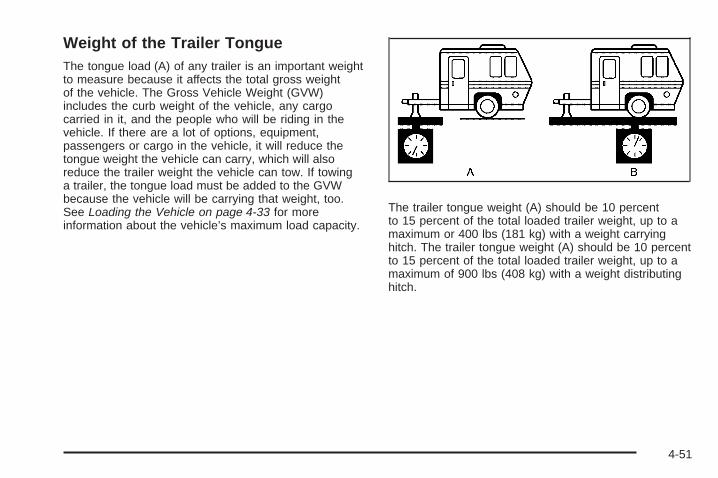
Weight of the Trailer TongueThe tongue load (A) of any trailer is an important weightto measure because it affects the total gross weightof the vehicle. The Gross Vehicle Weight (GVW)includes the curb weight of the vehicle, any cargocarried in it, and the people who will be riding in thevehicle. If there are a lot of options, equipment,passengers or cargo in the vehicle, it will reduce thetongue weight the vehicle can carry, which will alsoreduce the trailer weight the vehicle can tow. If towinga trailer, the tongue load must be added to the GVWbecause the vehicle will be carrying that weight, too.See Loading the Vehicle on page 4-33 for moreinformation about the vehicle’s maximum load capacity.
The trailer tongue weight (A) should be 10 percentto 15 percent of the total loaded trailer weight, up to amaximum or 400 lbs (181 kg) with a weight carryinghitch. The trailer tongue weight (A) should be 10 percentto 15 percent of the total loaded trailer weight, up to amaximum of 900 lbs (408 kg) with a weight distributinghitch.
4-51
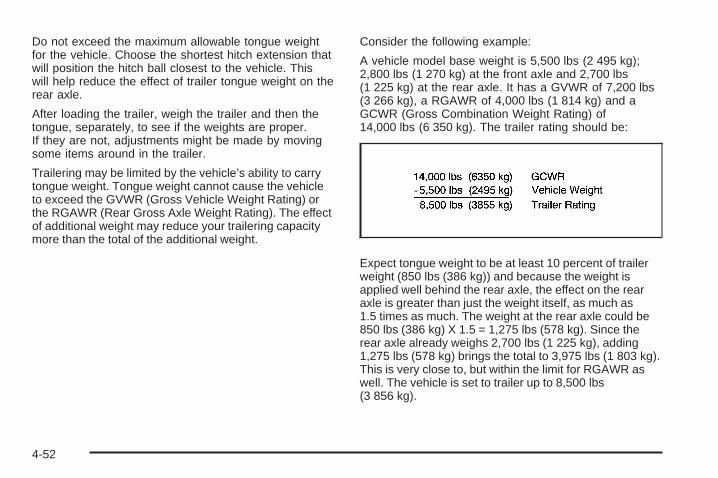
Do not exceed the maximum allowable tongue weightfor the vehicle. Choose the shortest hitch extension thatwill position the hitch ball closest to the vehicle. Thiswill help reduce the effect of trailer tongue weight on therear axle.
After loading the trailer, weigh the trailer and then thetongue, separately, to see if the weights are proper.If they are not, adjustments might be made by movingsome items around in the trailer.
Trailering may be limited by the vehicle’s ability to carrytongue weight. Tongue weight cannot cause the vehicleto exceed the GVWR (Gross Vehicle Weight Rating) orthe RGAWR (Rear Gross Axle Weight Rating). The effectof additional weight may reduce your trailering capacitymore than the total of the additional weight.
Consider the following example:
A vehicle model base weight is 5,500 lbs (2 495 kg);2,800 lbs (1 270 kg) at the front axle and 2,700 lbs(1 225 kg) at the rear axle. It has a GVWR of 7,200 lbs(3 266 kg), a RGAWR of 4,000 lbs (1 814 kg) and aGCWR (Gross Combination Weight Rating) of14,000 lbs (6 350 kg). The trailer rating should be:
Expect tongue weight to be at least 10 percent of trailerweight (850 lbs (386 kg)) and because the weight isapplied well behind the rear axle, the effect on the rearaxle is greater than just the weight itself, as much as1.5 times as much. The weight at the rear axle could be850 lbs (386 kg) X 1.5 = 1,275 lbs (578 kg). Since therear axle already weighs 2,700 lbs (1 225 kg), adding1,275 lbs (578 kg) brings the total to 3,975 lbs (1 803 kg).This is very close to, but within the limit for RGAWR aswell. The vehicle is set to trailer up to 8,500 lbs(3 856 kg).
4-52

If the vehicle has many options and there is a front seatpassenger and two rear seat passengers with someluggage and gear in the vehicle as well. 300 lbs (136 kg)could be added to the front axle weight and 400 lbs(181 kg) to the rear axle weight. The vehicle now weighs:
Weight is still below 7,200 lbs (3 266 kg) and youmight think 700 additional pounds (318 kg) should besubtracted from the trailering capacity to stay withinGCWR limits. The maximum trailer would only be7,800 lbs (3 538 kg). You may go further and think thetongue weight should be limited to less than 1,000 lbs(454 kg) to avoid exceeding GVWR. But the effect on therear axle must still be considered. Because the rear axlenow weighs 3,100 lbs (1 406 kg), 900 lbs (408 kg) canbe put on the rear axle without exceeding RGAWR. Theeffect of tongue weight is about 1.5 times the actualweight. Dividing the 900 lbs (408 kg) by 1.5 leaves only600 lbs (272 kg) of tongue weight that can be handled.
Since tongue weight is usually at least 10 percent of totalloaded trailer weight, expect that the largest trailer thevehicle can properly handle is 6,000 lbs (2 721 kg).
It is important that the vehicle does not exceed any of itsratings — GCWR, GVWR, RGAWR, Maximum TrailerRating or Tongue Weight. The only way to be sure it isnot exceeding any of these ratings is to weigh the vehicleand trailer.
Total Weight on the Vehicle’s TiresBe sure the vehicle’s tires are inflated to the upperlimit for cold tires. These numbers can be found on theCertification/Tire Label located on the B-pillar below thedoor latch or see Loading the Vehicle on page 4-33 formore information. Make sure not to go over the GVW limitfor the vehicle, or the GAWR, including the weight of thetrailer tongue. If using a weight distributing hitch, makesure not to go over the rear axle limit before applying theweight distribution spring bars.
HitchesIt is important to have the correct hitch equipment.Crosswinds, large trucks going by and rough roadsare a few reasons why the right hitch is needed.
4-53
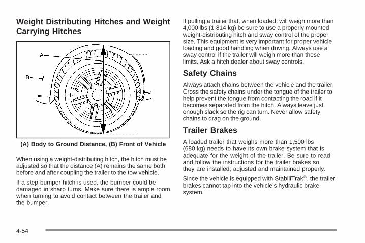
Weight Distributing Hitches and WeightCarrying Hitches
When using a weight-distributing hitch, the hitch must beadjusted so that the distance (A) remains the same bothbefore and after coupling the trailer to the tow vehicle.
If a step-bumper hitch is used, the bumper could bedamaged in sharp turns. Make sure there is ample roomwhen turning to avoid contact between the trailer andthe bumper.
If pulling a trailer that, when loaded, will weigh more than4,000 lbs (1 814 kg) be sure to use a properly mountedweight-distributing hitch and sway control of the propersize. This equipment is very important for proper vehicleloading and good handling when driving. Always use asway control if the trailer will weigh more than theselimits. Ask a hitch dealer about sway controls.
Safety ChainsAlways attach chains between the vehicle and the trailer.Cross the safety chains under the tongue of the trailer tohelp prevent the tongue from contacting the road if itbecomes separated from the hitch. Always leave justenough slack so the rig can turn. Never allow safetychains to drag on the ground.
Trailer BrakesA loaded trailer that weighs more than 1,500 lbs(680 kg) needs to have its own brake system that isadequate for the weight of the trailer. Be sure to readand follow the instructions for the trailer brakes sothey are installed, adjusted and maintained properly.
Since the vehicle is equipped with StabiliTrak®, the trailerbrakes cannot tap into the vehicle’s hydraulic brakesystem.
(A) Body to Ground Distance, (B) Front of Vehicle
4-54

Driving with a Trailer
{CAUTION:
When towing a trailer, exhaust gases may collectat the rear of the vehicle and enter if the liftgate,trunk/hatch, or rear-most window is open.
Engine exhaust contains carbon monoxide (CO)which cannot be seen or smelled. It can causeunconsciousness and even death.
To maximize safety when towing a trailer:• Have the exhaust system inspected for leaks
and make necessary repairs before startinga trip.
• Never drive with the liftgate, trunk/hatch, orrear-most window open.
• Fully open the air outlets on or under theinstrument panel.
• Adjust the Climate Control system to a settingthat brings in only outside air and set the fanspeed to the highest setting. See ClimateControl System in the Index.
For more information about carbon monoxide, seeEngine Exhaust on page 2-38.
Towing a trailer requires a certain amount of experience.Get to know the rig before setting out for the open road.Get acquainted with the feel of handling and braking withthe added weight of the trailer. And always keep in mindthat the vehicle you are driving is now longer and not asresponsive as the vehicle is by itself.
Before starting, check all trailer hitch parts andattachments, safety chains, electrical connectors, lamps,tires and mirror adjustments. If the trailer has electricbrakes, start the vehicle and trailer moving and thenapply the trailer brake controller by hand to be sure thebrakes are working. This checks the electrical connectionat the same time.
During the trip, check occasionally to be sure that theload is secure, and that the lamps and any trailer brakesare still working.
Following DistanceStay at least twice as far behind the vehicle ahead asyou would when driving the vehicle without a trailer. Thiscan help to avoid situations that require heavy brakingand sudden turns.
PassingMore passing distance is needed when towing a trailer.Because the rig is longer, it is necessary to go muchfarther beyond the passed vehicle before returning tothe lane.
4-55
Backing UpHold the bottom of the steering wheel with one hand.Then, to move the trailer to the left, move that handto the left. To move the trailer to the right, move yourhand to the right. Always back up slowly and, if possible,have someone guide you.
Making Turns
Notice: Making very sharp turns while traileringcould cause the trailer to come in contact with thevehicle. The vehicle could be damaged. Avoidmaking very sharp turns while trailering.
When turning with a trailer, make wider turns thannormal. Do this so the trailer will not strike soft shoulders,curbs, road signs, trees or other objects. Avoid jerky orsudden maneuvers. Signal well in advance.
Turn Signals When Towing a TrailerThe arrows on the instrument panel flash wheneversignaling a turn or lane change. Properly hooked up, thetrailer lamps also flash, telling other drivers the vehicle isturning, changing lanes or stopping.
When towing a trailer, the arrows on the instrument panelflash for turns even if the bulbs on the trailer are burnedout. For this reason you may think other drivers areseeing the signal when they are not. It is important tocheck occasionally to be sure the trailer bulbs are stillworking.
Driving On GradesReduce speed and shift to a lower gear before startingdown a long or steep downgrade. If the transmission isnot shifted down, the brakes might have to be used somuch that they would get hot and no longer work well.
Vehicles can tow in D (Drive). Shift the transmission toa lower gear if the transmission shifts too often underheavy loads and/or hilly conditions.
When towing at high altitude on steep uphill grades,consider the following: Engine coolant will boil at a lowertemperature than at normal altitudes. If the engine isturned off immediately after towing at high altitudeon steep uphill grades, the vehicle may show signssimilar to engine overheating. To avoid this, letthe engine run while parked, preferably on level ground,with the transmission in P (Park) for a few minutesbefore turning the engine off. If the overheat warningcomes on, see Engine Overheating on page 5-35.
4-56

Parking on Hills
{CAUTION:
Parking the vehicle on a hill with the trailer attachedcan be dangerous. If something goes wrong, the rigcould start to move. People can be injured, andboth the vehicle and the trailer can be damaged.When possible, always park the rig on a flatsurface.
If parking the rig on a hill:
1. Press the brake pedal, but do not shift into P (Park)yet. Turn the wheels into the curb if facing downhillor into traffic if facing uphill.
2. Have someone place chocks under the trailerwheels.
3. When the wheel chocks are in place, release thebrake pedal until the chocks absorb the load.
4. Reapply the brake pedal. Then apply the parkingbrake and shift into P (Park).
5. Release the brake pedal.
{CAUTION:
It can be dangerous to get out of the vehicle if theshift lever is not fully in P (Park) with the parkingbrake firmly set. The vehicle can roll.
If the engine has been left running, the vehicle canmove suddenly. You or others could be injured.To be sure the vehicle will not move, even whenon fairly level ground, use the steps that follow.
Always put the shift lever fully in P (Park) with theparking brake firmly set.
If the transfer case on four-wheel drive vehicles isin N (Neutral), the vehicle will be free to roll, evenif the shift lever is in P (Park). Be sure the transfercase is in a drive gear — not in N (Neutral).
See Four-Wheel Drive on page 2-30.
4-57

Leaving After Parking on a Hill1. Apply and hold the brake pedal while you:
• start the engine,
• shift into a gear, and
• release the parking brake.
2. Let up on the brake pedal.
3. Drive slowly until the trailer is clear of the chocks.
4. Stop and have someone pick up and store thechocks.
Maintenance When Trailer TowingThe vehicle needs service more often when pulling atrailer. See this manual’s Maintenance Schedule or Indexfor more information. Things that are especially importantin trailer operation are automatic transmission fluid,engine oil, axle lubricant, belts, cooling system and brakesystem. It is a good idea to inspect these before andduring the trip.
Check periodically to see that all hitch nuts and boltsare tight.
Trailer Wiring Harness
The vehicle may have a seven-wire trailer towingharness. This harness may have a seven-pinuniversal heavy-duty trailer connector (if equippedwith the trailering package) that is attached to abracket on the hitch platform or included with thefour-pin trailer towing harness. If the vehicle is notequipped with the heavy-duty trailer connector, onemay be purchased from your dealer/retailer.
4-58
The seven-wire harness contains the following trailercircuits:
• Yellow: Left Stop/Turn Signal
• Dark Green: Right Stop/Turn Signal
• Brown: Running Lamps
• White: Ground
• Light Green: Back-up Lamps
• Dark Blue: Electric Brakes
• Red: Battery Feed (The chassis wiring ring terminalmust be fastened to a stud on the underhoodelectrical center before the trailer feed will becomeactive.)
If towing a light-duty trailer with a standard four-wayround pin connector, an adapter connector is availablefrom your dealer/retailer.
If charging a remote (non-vehicle) battery, turn on theheadlamps to boost the vehicle system voltage andproperly charge the battery.
The vehicle is also equipped with wiring for an electrictrailer brake controller. These wires are located inside thevehicle on the driver side under the instrument panel.These wires should be connected to an electric trailerbrake controller by your dealer/retailer or a qualifiedservice center.
The vehicle may be equipped with a four-pin trailertowing harness. This harness has a four-pin trailerconnector that contains the following trailer circuits:
• Yellow: Left Stop/Turn Signal
• Dark Green: Right Stop/Turn Signal
• Brown: Running Lamps
• White: Ground
This harness also contains the following trailer circuitsthat are not connected to the four-pin trailer connector:
• Light Green: Back-Up Lamps
• Dark Blue: Electric Brakes
• Red: Battery Feed
If the vehicle is a TrailBlazer SS, a trailer wiring harnessextension, and instructions for installing this extension,were provided when the vehicle was delivered. Thisextension will allow the vehicle’s trailer wiring harness tobe more easily accessible. There is a four-way connectoron the harness. A seven-way adapter plug is alsoincluded if the trailer requires it.
4-59

✍ NOTES
4-60
Service ............................................................5-3Accessories and Modifications ..........................5-3California Proposition 65 Warning .....................5-4California Perchlorate Materials Requirements .....5-4Doing Your Own Service Work .........................5-4Adding Equipment to the Outside of
the Vehicle .................................................5-5Fuel ................................................................5-5
Gasoline Octane ............................................5-6Gasoline Specifications ....................................5-6California Fuel ...............................................5-6Additives .......................................................5-7Fuels in Foreign Countries ...............................5-7Filling the Tank ..............................................5-8Filling a Portable Fuel Container .....................5-10
Checking Things Under the Hood ....................5-10Hood Release ..............................................5-11Engine Compartment Overview .......................5-12Engine Oil ...................................................5-18Engine Oil Life System ..................................5-22Engine Air Cleaner/Filter ................................5-24Automatic Transmission Fluid .........................5-25Cooling System ............................................5-28Engine Coolant .............................................5-29Radiator Pressure Cap ..................................5-34Engine Overheating .......................................5-35
Engine Fan Noise .........................................5-36Power Steering Fluid .....................................5-37Windshield Washer Fluid ................................5-38Brakes ........................................................5-39Battery ........................................................5-42Jump Starting ...............................................5-43
All-Wheel Drive ..............................................5-48Rear Axle .......................................................5-49Four-Wheel Drive ............................................5-50Front Axle ......................................................5-51Headlamp Aiming ...........................................5-52Bulb Replacement ..........................................5-52
Halogen Bulbs ..............................................5-52Taillamps and Turn Signal Lamps ...................5-53License Plate Lamp ......................................5-54Replacement Bulbs .......................................5-54
Windshield Wiper Blade Replacement ..............5-55Tires ..............................................................5-58
Winter Tires .................................................5-59Tire Sidewall Labeling ...................................5-60Tire Terminology and Definitions .....................5-62Inflation - Tire Pressure .................................5-65High-Speed Operation ...................................5-66Tire Pressure Monitor System .........................5-67
Section 5 Service and Appearance Care
5-1
Tire Pressure Monitor Operation .....................5-69Tire Inspection and Rotation ...........................5-73When It Is Time for New Tires .......................5-74Buying New Tires .........................................5-75Different Size Tires and Wheels ......................5-77Uniform Tire Quality Grading ..........................5-78Wheel Alignment and Tire Balance ..................5-80Wheel Replacement ......................................5-80Tire Chains ..................................................5-81If a Tire Goes Flat ........................................5-82Tire Sealant and Compressor Kit ....................5-83Tire Sealant and Compressor Kit Storage .........5-92Changing a Flat Tire .....................................5-93Removing the Spare Tire and Tools ................5-94Removing the Flat Tire and Installing the
Spare Tire ................................................5-97Secondary Latch System ..............................5-103Storing a Flat or Spare Tire and Tools ...........5-106Spare Tire .................................................5-109
Appearance Care ..........................................5-109Interior Cleaning .........................................5-109Fabric/Carpet ..............................................5-111Leather ......................................................5-111Instrument Panel, Vinyl, and Other
Plastic Surfaces .......................................5-112
Care of Safety Belts ....................................5-112Weatherstrips .............................................5-112Washing Your Vehicle ..................................5-113Cleaning Exterior Lamps/Lenses ....................5-113Finish Care ................................................5-114Windshield, Backglass, and Wiper Blades .......5-114Aluminum Wheels .......................................5-115Tires .........................................................5-115Sheet Metal Damage ...................................5-116Finish Damage ...........................................5-116Underbody Maintenance ...............................5-116Chemical Paint Spotting ...............................5-116
Vehicle Identification .....................................5-117Vehicle Identification Number (VIN) ................5-117Service Parts Identification Label ...................5-117
Electrical System ..........................................5-118Add-On Electrical Equipment .........................5-118Headlamps .................................................5-118Windshield Wiper Fuses ...............................5-118Power Windows and Other Power Options ......5-118Fuses and Circuit Breakers ..........................5-119Engine Compartment Fuse Block ...................5-119Rear Underseat Fuse Block ..........................5-122
Capacities and Specifications ........................5-125
Section 5 Service and Appearance Care
5-2
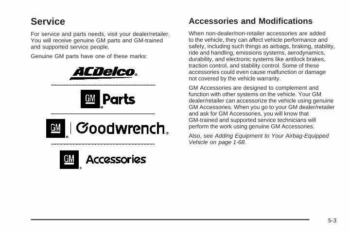
ServiceFor service and parts needs, visit your dealer/retailer.You will receive genuine GM parts and GM-trainedand supported service people.
Genuine GM parts have one of these marks:
Accessories and ModificationsWhen non-dealer/non-retailer accessories are addedto the vehicle, they can affect vehicle performance andsafety, including such things as airbags, braking, stability,ride and handling, emissions systems, aerodynamics,durability, and electronic systems like antilock brakes,traction control, and stability control. Some of theseaccessories could even cause malfunction or damagenot covered by the vehicle warranty.
GM Accessories are designed to complement andfunction with other systems on the vehicle. Your GMdealer/retailer can accessorize the vehicle using genuineGM Accessories. When you go to your GM dealer/retailerand ask for GM Accessories, you will know thatGM-trained and supported service technicians willperform the work using genuine GM Accessories.
Also, see Adding Equipment to Your Airbag-EquippedVehicle on page 1-68.
5-3

California Proposition 65 WarningMost motor vehicles, including this one, contain and/oremit chemicals known to the State of California to causecancer and birth defects or other reproductive harm.Engine exhaust, many parts and systems (includingsome inside the vehicle), many fluids, and somecomponent wear by-products contain and/or emitthese chemicals.
California Perchlorate MaterialsRequirementsCertain types of automotive applications, such asairbag initiators, seat belt pretensioners, and lithiumbatteries contained in remote keyless transmitters,may contain perchlorate materials. Special handlingmay be necessary. For additional information, seewww.dtsc.ca.gov/hazardouswaste/perchlorate.
Doing Your Own Service Work
{CAUTION:
You can be injured and the vehicle could bedamaged if you try to do service work on a vehiclewithout knowing enough about it.
• Be sure you have sufficient knowledge,experience, the proper replacement parts,and tools before attempting any vehiclemaintenance task.
• Be sure to use the proper nuts, bolts, andother fasteners. English and metric fastenerscan be easily confused. If the wrong fastenersare used, parts can later break or fall off.You could be hurt.
5-4

If doing some of your own service work, use the properservice manual. It tells you much more about how toservice the vehicle than this manual can. To orderthe proper service manual, see Service PublicationsOrdering Information on page 7-16.
This vehicle has an airbag system. Before attemptingto do your own service work, see Servicing YourAirbag-Equipped Vehicle on page 1-68.
Keep a record with all parts receipts and list themileage and the date of any service work performed.See Maintenance Record on page 6-16.
Adding Equipment to the Outside ofthe VehicleThings added to the outside of the vehicle can affect theairflow around it. This can cause wind noise and canaffect fuel economy and windshield washer performance.Check with your dealer/retailer before adding equipmentto the outside of the vehicle.
FuelUse of the recommended fuel is an important part ofthe proper maintenance of this vehicle. To help keep theengine clean and maintain optimum vehicle performance,we recommend the use of gasoline advertised asTOP TIER Detergent Gasoline.
The 8th digit of the Vehicle Identification Number (VIN)shows the code letter or number that identifies thevehicle’s engine. The VIN is at the top left of theinstrument panel. See Vehicle IdentificationNumber (VIN) on page 5-117.
5-5
Gasoline OctaneIf the vehicle has the 4.2L L6 engine (VIN Code S) orthe 5.3L V8 engine (VIN Code M), use regular unleadedgasoline with a posted octane rating of 87 or higher. If theoctane rating is less than 87, you might notice an audibleknocking noise when you drive, commonly referred toas spark knock. If this occurs, use a gasoline rated at87 octane or higher as soon as possible. If you are usinggasoline rated at 87 octane or higher and you hear heavyknocking, the engine needs service.
If the vehicle has the 6.0L V8 engine (VIN Code H),use premium unleaded gasoline with a posted octanerating of 91 or higher. You can also use regular unleadedgasoline rated at 87 octane or higher, but the vehicle’sacceleration could be slightly reduced, and you mightnotice a slight audible knocking noise, commonly referredto as spark knock. If the octane is less than 87, you mightnotice a heavy knocking noise when you drive. If thisoccurs, use a gasoline rated at 87 octane or higher assoon as possible. Otherwise, you could damage theengine. If you are using gasoline rated at 87 octane orhigher and you hear heavy knocking, the engine needsservice.
Gasoline SpecificationsAt a minimum, gasoline should meet ASTM specificationD 4814 in the United States or CAN/CGSB-3.5 or 3.511 inCanada. Some gasolines contain an octane-enhancingadditive called methylcyclopentadienyl manganesetricarbonyl (MMT). We recommend against the use ofgasolines containing MMT. See Additives on page 5-7for additional information.
California FuelIf the vehicle is certified to meet California EmissionsStandards, it is designed to operate on fuels that meetCalifornia specifications. See the underhood emissioncontrol label. If this fuel is not available in states adoptingCalifornia emissions standards, the vehicle will operatesatisfactorily on fuels meeting federal specifications, butemission control system performance might be affected.The malfunction indicator lamp could turn on and thevehicle might fail a smog-check test. See MalfunctionIndicator Lamp on page 3-39. If this occurs, return to yourauthorized dealer/retailer for diagnosis. If it is determinedthat the condition is caused by the type of fuel used,repairs might not be covered by the vehicle warranty.
5-6

AdditivesTo provide cleaner air, all gasolines in the United Statesare now required to contain additives that help preventengine and fuel system deposits from forming, allowingthe emission control system to work properly. In mostcases, you should not have to add anything to the fuel.However, some gasolines contain only the minimumamount of additive required to meet U.S. EnvironmentalProtection Agency regulations. To help keep fuel injectorsand intake valves clean, or if the vehicle experiencesproblems due to dirty injectors or valves, look for gasolinethat is advertised as TOP TIER Detergent Gasoline. Also,your dealer/retailer has additives that will help correct andprevent most deposit-related problems.
Gasolines containing oxygenates, such as ethers andethanol, and reformulated gasolines might be available inyour area. We recommend that you use these gasolines,if they comply with the specifications described earlier.However, E85 (85% ethanol) and other fuels containingmore than 10% ethanol must not be used in vehicles thatwere not designed for those fuels.
Notice: This vehicle was not designed for fuelthat contains methanol. Do not use fuel containingmethanol. It can corrode metal parts in the fuelsystem and also damage plastic and rubber parts.That damage would not be covered under thevehicle warranty.
Some gasolines that are not reformulated for lowemissions can contain an octane-enhancing additivecalled methylcyclopentadienyl manganese tricarbonyl(MMT); ask the attendant where you buy gasolinewhether the fuel contains MMT. We recommend againstthe use of such gasolines. Fuels containing MMT canreduce the life of spark plugs and the performance ofthe emission control system could be affected. Themalfunction indicator lamp might turn on. If this occurs,return to your dealer/retailer for service.
Fuels in Foreign CountriesIf you plan on driving in another country outside theUnited States or Canada, the proper fuel might be hardto find. Never use leaded gasoline or any other fuelnot recommended in the previous text on fuel. Costlyrepairs caused by use of improper fuel would notbe covered by the vehicle warranty.
To check the fuel availability, ask an auto club, orcontact a major oil company that does business in thecountry where you will be driving.
5-7

Filling the Tank
{CAUTION:
Fuel vapor burns violently and a fuel fire cancause bad injuries. To help avoid injuries to youand others, read and follow all the instructions onthe pump island. Turn off the engine when you arerefueling. Do not smoke if you are near fuel orrefueling the vehicle. Do not use cellular phones.Keep sparks, flames, and smoking materials awayfrom fuel. Do not leave the fuel pump unattendedwhen refueling the vehicle. This is against the lawin some places. Do not re-enter the vehicle whilepumping fuel. Keep children away from the fuelpump; never let children pump fuel.
The tethered fuel cap is located behind a hinged fueldoor on the driver side of the vehicle.
To remove the fuel cap, turn it slowly counterclockwise.
While refueling, hang the tethered fuel cap from thehook on the fuel door.
5-8
{CAUTION:
Fuel can spray out on you if you open the fuel captoo quickly. If you spill fuel and then somethingignites it, you could be badly burned. This spraycan happen if the tank is nearly full, and is morelikely in hot weather. Open the fuel cap slowly andwait for any hiss noise to stop. Then unscrew thecap all the way.
Be careful not to spill fuel. Do not top off or overfill thetank and wait a few seconds after you have finishedpumping before removing the nozzle. Clean fuel frompainted surfaces as soon as possible. See WashingYour Vehicle on page 5-113.
When replacing the fuel cap, turn it clockwise until itclicks. Make sure the cap is fully installed. The diagnosticsystem can determine if the fuel cap has been left off orimproperly installed. This would allow fuel to evaporateinto the atmosphere. See Malfunction Indicator Lamp onpage 3-39.
There may also be a light that comes on in theinstrument panel to let you know if the gas cap isnot properly installed. See Check Gas Cap Lighton page 3-47 for more information.
{CAUTION:
If a fire starts while you are refueling, do notremove the nozzle. Shut off the flow of fuel byshutting off the pump or by notifying the stationattendant. Leave the area immediately.
Notice: If you need a new fuel cap, be sure to getthe right type. Your dealer/retailer can get onefor you. If you get the wrong type, it may not fitproperly. This may cause the malfunction indicatorlamp to light and may damage the fuel tank andemissions system. See Malfunction Indicator Lampon page 3-39.
5-9
Filling a Portable Fuel Container
{CAUTION:
Never fill a portable fuel container while it is inthe vehicle. Static electricity discharge from thecontainer can ignite the fuel vapor. You can bebadly burned and the vehicle damaged if thisoccurs. To help avoid injury to you and others:
• Dispense fuel only into approved containers.• Do not fill a container while it is inside a
vehicle, in a vehicle’s trunk, pickup bed,or on any surface other than the ground.
• Bring the fill nozzle in contact with the insideof the fill opening before operating the nozzle.Contact should be maintained until the fillingis complete.
• Do not smoke while pumping fuel.• Do not use a cellular phone while
pumping fuel.
Checking Things Underthe Hood
{CAUTION:
Things that burn can get on hot engine parts andstart a fire. These include liquids like fuel, oil,coolant, brake fluid, windshield washer and otherfluids, and plastic or rubber. You or others couldbe burned. Be careful not to drop or spill thingsthat will burn onto a hot engine.
5-10
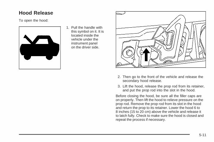
Hood ReleaseTo open the hood:
1. Pull the handle withthis symbol on it. It islocated inside thevehicle under theinstrument panelon the driver side.
2. Then go to the front of the vehicle and release thesecondary hood release.
3. Lift the hood, release the prop rod from its retainer,and put the prop rod into the slot in the hood.
Before closing the hood, be sure all the filler caps areon properly. Then lift the hood to relieve pressure on theprop rod. Remove the prop rod from its slot in the hoodand return the prop to its retainer. Lower the hood 6 to8 inches (15 to 20 cm) above the vehicle and release itto latch fully. Check to make sure the hood is closed andrepeat the process if necessary.
5-11
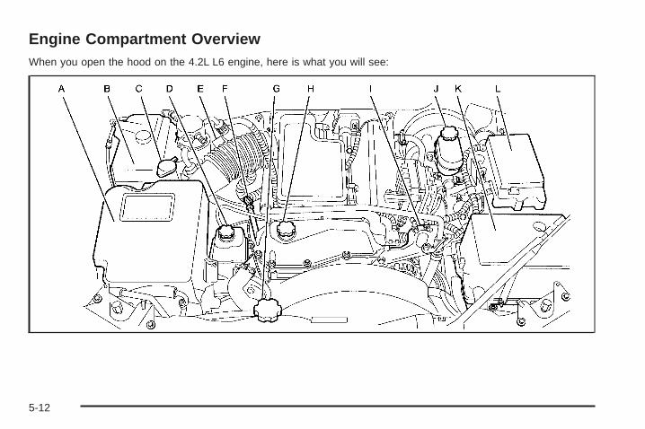
Engine Compartment OverviewWhen you open the hood on the 4.2L L6 engine, here is what you will see:
5-12
A. Engine Air Cleaner/Filter. See Engine AirCleaner/Filter on page 5-24.
B. Engine Coolant Recovery Tank. See Cooling Systemon page 5-28.
C. Windshield Washer Fluid Reservoir. See “AddingWasher Fluid” under Windshield Washer Fluidon page 5-38.
D. Power Steering Fluid Reservoir. See Power SteeringFluid on page 5-37.
E. Automatic Transmission Fluid Dipstick (Out of View).See “Checking the Fluid Level” under AutomaticTransmission Fluid on page 5-25.
F. Engine Oil Dipstick. See “Checking Engine Oil”under Engine Oil on page 5-18.
G. Radiator Pressure Cap. See Radiator Pressure Capon page 5-34.
H. Engine Oil Fill Cap. See “When to Add Engine Oil”under Engine Oil on page 5-18.
I. Remote Negative (−) Terminal (Marked GND).See Jump Starting on page 5-43.
J. Brake Master Cylinder Reservoir. See “Brake Fluid”under Brakes on page 5-39.
K. Battery. See Battery on page 5-42.L. Engine Compartment Fuse Block. See Engine
Compartment Fuse Block on page 5-119.
5-13

When you open the hood on the 5.3L V8 engine, here is what you will see:
5-14
A. Engine Coolant Recovery Tank. See Cooling Systemon page 5-28.
B. Engine Air Cleaner/Filter. See Engine AirCleaner/Filter on page 5-24.
C. Windshield Washer Fluid Reservoir. See “AddingWasher Fluid” under Windshield Washer Fluidon page 5-38.
D. Engine Oil Fill Cap. See “When to Add Engine Oil”under Engine Oil on page 5-18.
E. Automatic Transmission Fluid Dipstick.See “Checking the Fluid Level” underAutomatic Transmission Fluid on page 5-25.
F. Engine Oil Dipstick. See “Checking Engine Oil”under Engine Oil on page 5-18.
G. Radiator Pressure Cap. See Radiator Pressure Capon page 5-34.
H. Remote Negative (−) Terminal (Marked GND).See Jump Starting on page 5-43.
I. Power Steering Fluid Reservoir. See Power SteeringFluid on page 5-37.
J. Brake Master Cylinder Reservoir. See “Brake Fluid”under Brakes on page 5-39.
K. Engine Compartment Fuse Block. See EngineCompartment Fuse Block on page 5-119.
L. Battery. See Battery on page 5-42.
5-15

When you open the hood on the 6.0L V8 TrailBlazer SS engine, here is what you will see:
5-16

A. Engine Coolant Recovery Tank. See Cooling Systemon page 5-28.
B. Engine Air Cleaner/Filter. See Engine AirCleaner/Filter on page 5-24.
C. Windshield Washer Fluid Reservoir. See “AddingWasher Fluid” under Windshield Washer Fluidon page 5-38.
D. Engine Oil Fill Cap (Under Engine Cover).See “When to Add Engine Oil” under EngineOil on page 5-18.
E. Engine Oil Dipstick (Out of View). See “CheckingEngine Oil” under Engine Oil on page 5-18.
F. Automatic Transmission Fluid Dipstick.See “Checking the Fluid Level” under AutomaticTransmission Fluid on page 5-25.
G. Radiator Pressure Cap. See Radiator Pressure Capon page 5-34.
H. Remote Negative (−) Terminal (Marked GND).See Jump Starting on page 5-43.
I. Power Steering Fluid Reservoir. See Power SteeringFluid on page 5-37.
J. Brake Master Cylinder Reservoir. See “Brake Fluid”under Brakes on page 5-39.
K. Engine Compartment Fuse Block. See EngineCompartment Fuse Block on page 5-119.
L. Battery. See Battery on page 5-42.
5-17

Engine Oil
Checking Engine OilIt is a good idea to check the engine oil every time youget fuel. In order to get an accurate reading, the oilmust be warm and the vehicle must be on level ground.
The engine oil dipstick handle is a yellow loop.See Engine Compartment Overview on page 5-12for the location of the engine oil dipstick.
1. Turn off the engine and give the oil several minutesto drain back into the oil pan. If you do not do this,the oil dipstick might not show the actual level.
2. Pull out the dipstick and clean it with a paper towelor cloth, then push it back in all the way. Remove itagain, keeping the tip down, and check the level.
When to Add Engine Oil
If the oil is below the L mark for the L6 engineor the cross-hatched area at the tip of the dipstickfor the V8 engine, add at least one quart/liter of therecommended oil. This section explains what kindof oil to use. For engine oil crankcase capacity, seeCapacities and Specifications on page 5-125.
L6 Engine
V8 Engine
5-18
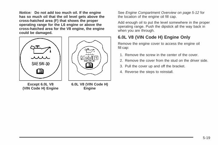
Notice: Do not add too much oil. If the enginehas so much oil that the oil level gets above thecross-hatched area (F) that shows the properoperating range for the L6 engine or above thecross-hatched area for the V8 engine, the enginecould be damaged.
See Engine Compartment Overview on page 5-12 forthe location of the engine oil fill cap.
Add enough oil to put the level somewhere in the properoperating range. Push the dipstick all the way back inwhen you are through.
6.0L V8 (VIN Code H) Engine OnlyRemove the engine cover to access the engine oilfill cap:
1. Remove the screw in the center of the cover.
2. Remove the cover from the stud on the driver side.
3. Pull the cover up and off the bracket.
4. Reverse the steps to reinstall.
Except 6.0L V8(VIN Code H) Engine
6.0L V8 (VIN Code H)Engine
5-19

What Kind of Engine Oil to Use
Except Vehicles with 6.0L V8 (VIN Code H)EngineLook for three things:
• GM6094M
Use only an oil that meets GM Standard GM6094M.
• SAE 5W-30
SAE 5W-30 is best for the vehicle. These numberson an oil container show its viscosity, or thickness.Do not use other viscosity oils such as SAE 20W-50.
• American Petroleum Institute (API) starburstsymbol
Oils meeting theserequirements should havethe starburst symbol on thecontainer. This symbolindicates that the oil hasbeen certified by theAmerican PetroleumInstitute (API).
Notice: Use only engine oil identified as meetingGM Standard GM6094M and showing the AmericanPetroleum Institute Certified For Gasoline Enginesstarburst symbol. Failure to use the recommendedoil can result in engine damage not covered bythe vehicle warranty.
5-20

For 6.0L V8 (VIN Code H) EngineVehicles OnlyLook for three things:
• GM4718M
This vehicle’s engine requires a special oil meetingGM Standard GM4718M. Oils meeting this standardmay be identified as synthetic. However, not allsynthetic oils will meet this GM standard. Use onlyan oil that meets GM Standard GM4718M.
Notice: Using oils that do not have the GM4718MStandard designation can cause engine damage notcovered by the vehicle warranty.
• SAE 5W-30
SAE 5W-30 is best for the vehicle. These numberson an oil container show its viscosity, or thickness.Do not use other viscosity oils such as SAE 20W-50.
• American Petroleum Institute (API) starburstsymbol
Oils meeting theserequirements should havethe starburst symbol on thecontainer. This symbolindicates that the oil hasbeen certified by theAmerican PetroleumInstitute (API).
This vehicle’s engine was filled at the factory with aMobil 1® synthetic oil meeting all requirements for thisvehicle.
5-21

Substitute Engine Oil: When adding oil to maintainengine oil level, oil meeting GM Standard GM4718Mmight not be available. You can add substitute oildesignated SAE 5W-30 with the starburst symbol at alltemperatures. Substitute oil not meeting GM StandardGM4718M should not be used for an oil change.
Cold Temperature Operation
Except Vehicles with 6.0L V8 (VIN Code H)EngineIf in an area of extreme cold, where the temperaturefalls below −20°F (−29°C), use either an SAE 5W-30synthetic oil or an SAE 0W-30 engine oil. Both provideeasier cold starting for the engine at extremely lowtemperatures. Always use an oil that meets the requiredspecification, GM6094M. See “What Kind of Engine Oilto Use” for more information.
Engine Oil Additives / Engine OilFlushesDo not add anything to the oil. The recommended oilswith the starburst symbol that meet GM standards areall that is needed for good performance and engineprotection.
Engine oil system flushes are not recommended andcould cause engine damage not covered by the vehiclewarranty.
Engine Oil Life SystemWhen to Change Engine OilThis vehicle has a computer system that indicates whento change the engine oil and filter. This is based onengine revolutions and engine temperature, and not onmileage. Based on driving conditions, the mileage atwhich an oil change is indicated can vary considerably.For the oil life system to work properly, the systemmust be reset every time the oil is changed.When the system has calculated that oil life has beendiminished, it indicates that an oil change is necessary.A change engine oil light comes on, and, if the vehiclehas a Driver Information Center (DIC), a CHANGEENGINE OIL message comes on. See Change EngineOil Light on page 3-43 and DIC Warnings and Messageson page 3-51. Change the oil as soon as possible withinthe next 600 miles (1 000 km). It is possible that, if drivingunder the best conditions, the oil life system might notindicate that an oil change is necessary for over a year.However, the engine oil and filter must be changed atleast once a year and at this time the system must bereset. Your dealer/retailer has trained people who willperform this work using genuine parts and reset thesystem. It is also important to check the oil regularlyand keep it at the proper level.If the system is ever reset accidentally, the oil must bechanged at 3,000 miles (5 000 km) since the last oilchange. Remember to reset the oil life system wheneverthe oil is changed.
5-22
How to Reset the Engine Oil LifeSystemThe Engine Oil Life System calculates when to changethe engine oil and filter based on vehicle use. Wheneverthe oil is changed, reset the system so it can calculatewhen the next oil change is required. If a situation occurswhere the oil is changed prior to a change engine oil lightor CHANGE ENGINE OIL message being turned on,reset the system.
To reset the Engine Oil Life System:
1. Turn the ignition key to ON/RUN with theengine off.
2. Fully press and release the accelerator pedal slowlythree times within five seconds.The change engine oil light will flash while thesystem is resetting.
3. When the light stops flashing, turn the key toLOCK/OFF.
If the light/message comes back on when the vehicleis started, the engine oil life system has not reset.Repeat the procedure.
What to Do with Used OilUsed engine oil contains certain elements that can beunhealthy for your skin and could even cause cancer.Do not let used oil stay on your skin for very long. Cleanyour skin and nails with soap and water, or a good handcleaner. Wash or properly dispose of clothing or ragscontaining used engine oil. See the manufacturer’swarnings about the use and disposal of oil products.
Used oil can be a threat to the environment. If youchange your own oil, be sure to drain all the oil from thefilter before disposal. Never dispose of oil by putting itin the trash, pouring it on the ground, into sewers, or intostreams or bodies of water. Recycle it by taking it to aplace that collects used oil.
5-23

Engine Air Cleaner/Filter
See Engine CompartmentOverview on page 5-12for the location of theengine air cleaner/filter.
When to Inspect the Engine AirCleaner/FilterInspect the air cleaner/filter at the Maintenance IIintervals and replace at the first oil change after each50,000 mile (80 000 km) interval. See ScheduledMaintenance on page 6-4 for more information.If you are driving in dusty/dirty conditions, inspectthe filter at each engine oil change.
How to Inspect the Engine AirCleaner/FilterTo inspect the air cleaner/filter remove the filter from thevehicle and lightly shake the filter to release loose dustand dirt. If the filter remains caked with dirt, a new filteris required.
To inspect or replace the engine air cleaner/filter, do thefollowing:
1. Remove the screws on the engine air cleaner/filterand lift off the cover.
2. Remove the air cleaner/filter from the housing. Careshould be taken to dislodge as little dirt as possible.
3. Inspect or replace the engine air cleaner/filter.
4. Reinstall the cover and tighten the screws.
4.2L L6 Engine shown,5.3L and 6.0L V8Engines similar
5-24
{CAUTION:
Operating the engine with the air cleaner/filter offcan cause you or others to be burned. The aircleaner not only cleans the air; it helps to stopflames if the engine backfires. If it is not thereand the engine backfires, you could be burned.Do not drive with it off, and be careful workingon the engine with the air cleaner/filter off.
Notice: If the air cleaner/filter is off, a backfire cancause a damaging engine fire. And, dirt can easily getinto the engine, which will damage it. Always havethe air cleaner/filter in place when you are driving.
Automatic Transmission Fluid
When to Check and Change AutomaticTransmission FluidA good time to check the automatic transmission fluidlevel is when the engine oil is changed.
Change the fluid and filter at the intervals listed inAdditional Required Services on page 6-6, and be sureto use the transmission fluid listed in RecommendedFluids and Lubricants on page 6-12.
5-25

How to Check Automatic TransmissionFluidBecause this operation can be a little difficult, you maychoose to have this done at the dealer/retailer servicedepartment.
If you do it yourself, be sure to follow all the instructionshere, or you could get a false reading on the dipstick.
Notice: Too much or too little fluid can damageyour transmission. Too much can mean that someof the fluid could come out and fall on hot engineparts or exhaust system parts, starting a fire.Too little fluid could cause the transmission tooverheat. Be sure to get an accurate reading ifyou check your transmission fluid.
Wait at least 30 minutes before checking thetransmission fluid level if you have been driving:
• When outside temperatures are above 90°F (32°C).
• At high speed for quite a while.
• In heavy traffic — especially in hot weather.
• While pulling a trailer.
To get the right reading, the fluid should be at normaloperating temperature, which is 180°F to 200°F(82°C to 93°C).
Get the vehicle warmed up by driving about15 miles (24 km) when outside temperatures areabove 50°F (10°C). If it is colder than 50°F (10°C),drive the vehicle in 3 (Third) until the engine temperaturegage moves and then remains steady for 10 minutes.
A cold fluid check can be made after the vehicle hasbeen sitting for eight hours or more with the engine off,but this is used only as a reference. Let the engine runat idle for five minutes if outside temperatures are 50°F(10°C) or more. If it is colder than 50°F (10°C), you mayhave to idle the engine longer. Should the fluid level below during this cold check, you must check the fluid hotbefore adding fluid. Checking the fluid hot will give amore accurate reading of the fluid level.
5-26
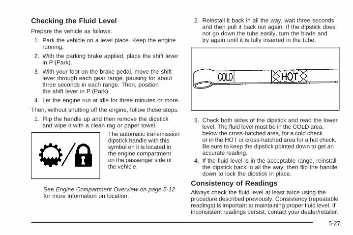
Checking the Fluid LevelPrepare the vehicle as follows:
1. Park the vehicle on a level place. Keep the enginerunning.
2. With the parking brake applied, place the shift leverin P (Park).
3. With your foot on the brake pedal, move the shiftlever through each gear range, pausing for aboutthree seconds in each range. Then, positionthe shift lever in P (Park).
4. Let the engine run at idle for three minutes or more.
Then, without shutting off the engine, follow these steps:
1. Flip the handle up and then remove the dipstickand wipe it with a clean rag or paper towel.
The automatic transmissiondipstick handle with thissymbol on it is located inthe engine compartmenton the passenger side ofthe vehicle.
See Engine Compartment Overview on page 5-12for more information on location.
2. Reinstall it back in all the way, wait three secondsand then pull it back out again. If the dipstick doesnot go down the tube easily, turn the blade andtry again until it is fully inserted in the tube.
3. Check both sides of the dipstick and read the lowerlevel. The fluid level must be in the COLD area,below the cross-hatched area, for a cold checkor in the HOT or cross-hatched area for a hot check.Be sure to keep the dipstick pointed down to get anaccurate reading.
4. If the fluid level is in the acceptable range, reinstallthe dipstick back in all the way; then flip the handledown to lock the dipstick in place.
Consistency of ReadingsAlways check the fluid level at least twice using theprocedure described previously. Consistency (repeatablereadings) is important to maintaining proper fluid level. Ifinconsistent readings persist, contact your dealer/retailer.
5-27

How to Add Automatic TransmissionFluidRefer to the Maintenance Schedule to determine whatkind of transmission fluid to use. See RecommendedFluids and Lubricants on page 6-12.
Add fluid only after checking the transmission fluid whileit is hot. A cold check is used only as a reference. If thefluid level is low, add only enough of the proper fluid tobring the level up to the HOT area for a hot check. It doesnot take much fluid, generally less than one pint (0.5 L).Do not overfill.
Notice: Use of the incorrect automatic transmissionfluid may damage the vehicle, and the damagesmay not be covered by the vehicle’s warranty.Always use the automatic transmission fluid listed inRecommended Fluids and Lubricants on page 6-12.
• After adding fluid, recheck the fluid level as describedunder “How to Check Automatic Transmission Fluid”earlier in this section.
• When the correct fluid level is obtained, push thedipstick back in all the way; then flip the handledown to lock the dipstick in place.
Cooling SystemThe cooling system allows the engine to maintain thecorrect working temperature.
5.3L V8 Engine shown, 4.2L L6 and 6.0L V8 Enginessimilar
A. Coolant Recovery TankB. Radiator Pressure CapC. Engine Fan
5-28

{CAUTION:
An electric engine cooling fan under the hood canstart up even when the engine is not running andcan cause injury. Keep hands, clothing, and toolsaway from any underhood electric fan.
{CAUTION:
Heater and radiator hoses, and other engine parts,can be very hot. Do not touch them. If you do,you can be burned.
Do not run the engine if there is a leak. If you runthe engine, it could lose all coolant. That couldcause an engine fire, and you could be burned.Get any leak fixed before you drive the vehicle.
Notice: Using coolant other than DEX-COOL® cancause premature engine, heater core, or radiatorcorrosion. In addition, the engine coolant couldrequire changing sooner, at 30,000 miles (50 000 km)or 24 months, whichever occurs first. Any repairswould not be covered by the vehicle warranty.Always use DEX-COOL® (silicate-free) coolantin the vehicle.
Engine CoolantThe cooling system in the vehicle is filled withDEX-COOL®. This coolant is designed to remain in thevehicle for five years or 150,000 miles (240 000 km),whichever occurs first.
The following explains the cooling system and howto check and add coolant when it is low. If thereis a problem with engine overheating, see EngineOverheating on page 5-35.
5-29

What to Use
{CAUTION:
Adding only plain water to the cooling system canbe dangerous. Plain water, or some other liquidsuch as alcohol, can boil before the proper coolantmixture will. The vehicle’s coolant warning systemis set for the proper coolant mixture. With plainwater or the wrong mixture, the engine could gettoo hot but you would not get the overheatwarning. The engine could catch fire and you orothers could be burned. Use a 50/50 mixture ofclean, drinkable water and DEX-COOL® coolant.
Use a 50/50 mixture of clean, drinkable water andDEX-COOL coolant. If using this mixture, nothing elseneeds to be added. This mixture:
• Gives freezing protection down to −34°F (−37°C),outside temperature.
• Gives boiling protection up to 265°F (129°C),engine temperature.
• Protects against rust and corrosion.
• Will not damage aluminum parts.
• Helps keep the proper engine temperature.
Notice: If an improper coolant mixture is used,the engine could overheat and be badly damaged.The repair cost would not be covered by the vehiclewarranty. Too much water in the mixture can freezeand crack the engine, radiator, heater core, andother parts.
Notice: If extra inhibitors and/or additives are usedin the vehicle’s cooling system, the vehicle couldbe damaged. Use only the proper mixture ofthe engine coolant listed in this manual for thecooling system. See Recommended Fluids andLubricants on page 6-12 for more information.
5-30

Checking CoolantThe vehicle must be on a level surface when checkingthe coolant level.
Check to see if coolant is visible in the coolant recoverytank. If the coolant inside the coolant recovery tank isboiling, do not do anything else until it cools down. Ifcoolant is visible but the coolant level is not at or abovethe FULL COLD mark, add a 50/50 mixture of clean,drinkable water and DEX-COOL coolant at the coolantrecovery tank, but be sure the cooling system is coolbefore this is done.
The coolant level should be at least up to theFULL COLD mark. If it is not, there may be a leakin the cooling system.
How to Add Coolant to theRecovery Tank
{CAUTION:
You can be burned if you spill coolant on hotengine parts. Coolant contains ethylene glycoland it will burn if the engine parts are hot enough.Do not spill coolant on a hot engine.
Notice: This vehicle has a specific coolant fillprocedure. Failure to follow this procedure couldcause the engine to overheat and be severelydamaged.
If coolant is needed, add the proper DEX-COOL coolantmixture at the coolant recovery tank.
When the coolant in the coolant recovery tank is at theFULL COLD mark, start the vehicle.
5-31
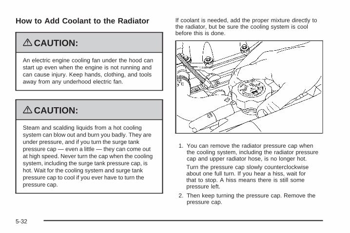
How to Add Coolant to the Radiator
{CAUTION:
An electric engine cooling fan under the hood canstart up even when the engine is not running andcan cause injury. Keep hands, clothing, and toolsaway from any underhood electric fan.
{CAUTION:
Steam and scalding liquids from a hot coolingsystem can blow out and burn you badly. They areunder pressure, and if you turn the surge tankpressure cap — even a little — they can come outat high speed. Never turn the cap when the coolingsystem, including the surge tank pressure cap, ishot. Wait for the cooling system and surge tankpressure cap to cool if you ever have to turn thepressure cap.
If coolant is needed, add the proper mixture directly tothe radiator, but be sure the cooling system is coolbefore this is done.
1. You can remove the radiator pressure cap whenthe cooling system, including the radiator pressurecap and upper radiator hose, is no longer hot.Turn the pressure cap slowly counterclockwiseabout one full turn. If you hear a hiss, wait forthat to stop. A hiss means there is still somepressure left.
2. Then keep turning the pressure cap. Remove thepressure cap.
5-32
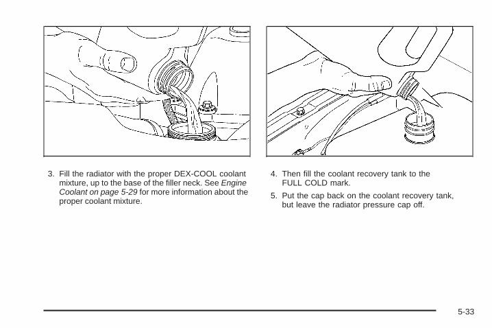
3. Fill the radiator with the proper DEX-COOL coolantmixture, up to the base of the filler neck. See EngineCoolant on page 5-29 for more information about theproper coolant mixture.
4. Then fill the coolant recovery tank to theFULL COLD mark.
5. Put the cap back on the coolant recovery tank,but leave the radiator pressure cap off.
5-33
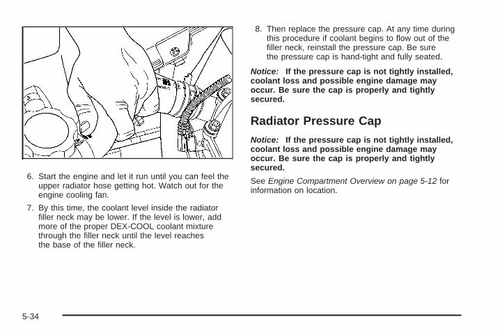
6. Start the engine and let it run until you can feel theupper radiator hose getting hot. Watch out for theengine cooling fan.
7. By this time, the coolant level inside the radiatorfiller neck may be lower. If the level is lower, addmore of the proper DEX-COOL coolant mixturethrough the filler neck until the level reachesthe base of the filler neck.
8. Then replace the pressure cap. At any time duringthis procedure if coolant begins to flow out of thefiller neck, reinstall the pressure cap. Be surethe pressure cap is hand-tight and fully seated.
Notice: If the pressure cap is not tightly installed,coolant loss and possible engine damage mayoccur. Be sure the cap is properly and tightlysecured.
Radiator Pressure CapNotice: If the pressure cap is not tightly installed,coolant loss and possible engine damage mayoccur. Be sure the cap is properly and tightlysecured.
See Engine Compartment Overview on page 5-12 forinformation on location.
5-34

Engine OverheatingThe vehicle has several indicators to warn of engineoverheating.
You will find a coolant temperature gage on the vehicle’sinstrument panel. See Engine Coolant TemperatureGage on page 3-38 for more information.
If the vehicle has a Driver Information Center (DIC),the display will show an Engine Coolant Hot/EngineOverheated message. See DIC Warnings and Messageson page 3-51 for more information.
You may decide not to lift the hood when this warningappears, but instead get service help right away.See Roadside Assistance Program on page 7-7.
If you do decide to lift the hood, make sure the vehicleis parked on a level surface.
Then check to see if the engine cooling fans arerunning. If the engine is overheating, both fans shouldbe running. If they are not, do not continue to runthe engine and have the vehicle serviced.
Notice: Engine damage from running the enginewithout coolant is not covered by the warranty.
Notice: If the engine catches fire because of beingdriven with no coolant, your vehicle can be badlydamaged. The costly repairs would not be coveredby the vehicle warranty.
If Steam Is Coming From The EngineCompartment
{CAUTION:
Steam from an overheated engine can burn youbadly, even if you just open the hood. Stay awayfrom the engine if you see or hear steam comingfrom it. Just turn it off and get everyone away fromthe vehicle until it cools down. Wait until there is nosign of steam or coolant before you open the hood.
If you keep driving when your engine is overheated,the liquids in it can catch fire. You or others couldbe badly burned. Stop your engine if it overheats,and get out of the vehicle until the engine is cool.
5-35

If No Steam Is Coming From TheEngine CompartmentIf an engine overheat warning is displayed but nosteam can be seen or heard, the problem may not betoo serious. Sometimes the engine can get a little toohot when the vehicle:
• Climbs a long hill on a hot day.
• Stops after high-speed driving.
• Idles for long periods in traffic.
• Tows a trailer.
If the overheat warning is displayed with no sign ofsteam:
1. Turn the air conditioning off.
2. Turn the heater on to the highest temperature andto the highest fan speed. Open the windows asnecessary.
3. In heavy traffic, let the engine idle in N (Neutral)while stopped. If it is safe to do so, pull off theroad, shift to P (Park) or N (Neutral) and letthe engine idle.
If the temperature overheat gage is no longer in theoverheat zone or an overheat warning no longerdisplays, the vehicle can be driven. Continue to drivethe vehicle slow for about 10 minutes. Keep a safe
vehicle distance from the car in front of you. If thewarning does not come back on, continue to drivenormally.
If the warning continues, pull over, stop, and park thevehicle right away.
If there is no sign of steam, idle the engine for threeminutes while parked. If the warning is still displayed,turn off the engine until it cools down.
Engine Fan NoiseThe vehicle has a clutched engine cooling fan. Whenthe clutch is engaged, the fan spins faster to providemore air to cool the engine. In most everyday drivingconditions the clutch is not engaged. This improves fueleconomy and reduces fan noise. Under heavy vehicleloading, trailer towing, and/or high outside temperatures,the fan speed increases when the clutch engages soyou may hear an increase in fan noise. This is normaland should not be mistaken as the transmission slippingor making extra shifts. It is merely the cooling systemfunctioning properly. The fan will slow down whenadditional cooling is not required and the clutchdisengages.
You may also hear this fan noise when the engine isstarted. The sound will go away as the fan clutchdisengages.
5-36
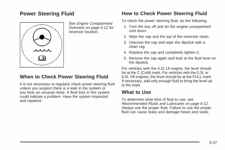
Power Steering Fluid
See Engine CompartmentOverview on page 5-12 forreservoir location.
When to Check Power Steering FluidIt is not necessary to regularly check power steering fluidunless you suspect there is a leak in the system oryou hear an unusual noise. A fluid loss in this systemcould indicate a problem. Have the system inspectedand repaired.
How to Check Power Steering FluidTo check the power steering fluid, do the following:
1. Turn the key off and let the engine compartmentcool down.
2. Wipe the cap and the top of the reservoir clean.
3. Unscrew the cap and wipe the dipstick with aclean rag.
4. Replace the cap and completely tighten it.
5. Remove the cap again and look at the fluid level onthe dipstick.
For vehicles with the 4.2L L6 engine, the level shouldbe at the C (Cold) mark. For vehicles with the 5.3L or6.0L V8 engines, the level should be at the FULL mark.If necessary, add only enough fluid to bring the level upto the mark.
What to UseTo determine what kind of fluid to use, seeRecommended Fluids and Lubricants on page 6-12.Always use the proper fluid. Failure to use the properfluid can cause leaks and damage hoses and seals.
5-37
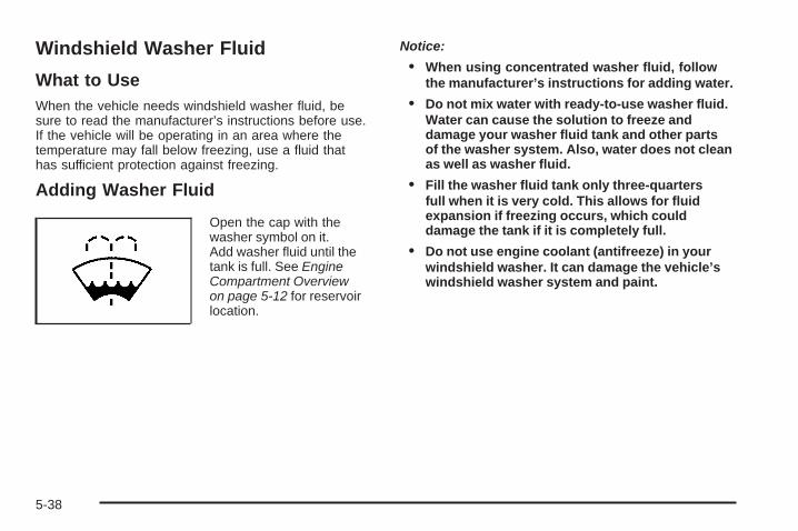
Windshield Washer Fluid
What to UseWhen the vehicle needs windshield washer fluid, besure to read the manufacturer’s instructions before use.If the vehicle will be operating in an area where thetemperature may fall below freezing, use a fluid thathas sufficient protection against freezing.
Adding Washer Fluid
Open the cap with thewasher symbol on it.Add washer fluid until thetank is full. See EngineCompartment Overviewon page 5-12 for reservoirlocation.
Notice:
• When using concentrated washer fluid, followthe manufacturer’s instructions for adding water.
• Do not mix water with ready-to-use washer fluid.Water can cause the solution to freeze anddamage your washer fluid tank and other partsof the washer system. Also, water does not cleanas well as washer fluid.
• Fill the washer fluid tank only three-quartersfull when it is very cold. This allows for fluidexpansion if freezing occurs, which coulddamage the tank if it is completely full.
• Do not use engine coolant (antifreeze) in yourwindshield washer. It can damage the vehicle’swindshield washer system and paint.
5-38
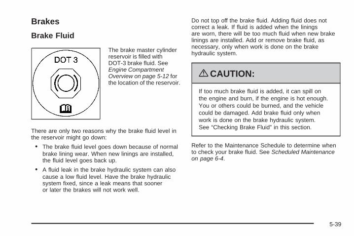
Brakes
Brake Fluid
The brake master cylinderreservoir is filled withDOT-3 brake fluid. SeeEngine CompartmentOverview on page 5-12 forthe location of the reservoir.
There are only two reasons why the brake fluid level inthe reservoir might go down:
• The brake fluid level goes down because of normalbrake lining wear. When new linings are installed,the fluid level goes back up.
• A fluid leak in the brake hydraulic system can alsocause a low fluid level. Have the brake hydraulicsystem fixed, since a leak means that sooneror later the brakes will not work well.
Do not top off the brake fluid. Adding fluid does notcorrect a leak. If fluid is added when the liningsare worn, there will be too much fluid when new brakelinings are installed. Add or remove brake fluid, asnecessary, only when work is done on the brakehydraulic system.
{CAUTION:
If too much brake fluid is added, it can spill onthe engine and burn, if the engine is hot enough.You or others could be burned, and the vehiclecould be damaged. Add brake fluid only whenwork is done on the brake hydraulic system.See “Checking Brake Fluid” in this section.
Refer to the Maintenance Schedule to determine whento check your brake fluid. See Scheduled Maintenanceon page 6-4.
5-39
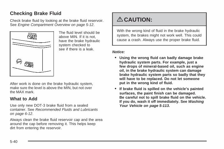
Checking Brake FluidCheck brake fluid by looking at the brake fluid reservoir.See Engine Compartment Overview on page 5-12.
The fluid level should beabove MIN. If it is not,have the brake hydraulicsystem checked tosee if there is a leak.
After work is done on the brake hydraulic system,make sure the level is above the MIN, but not overthe MAX mark.
What to AddUse only new DOT-3 brake fluid from a sealedcontainer. See Recommended Fluids and Lubricantson page 6-12.
Always clean the brake fluid reservoir cap and the areaaround the cap before removing it. This helps keepdirt from entering the reservoir.
{CAUTION:
With the wrong kind of fluid in the brake hydraulicsystem, the brakes might not work well. This couldcause a crash. Always use the proper brake fluid.
Notice:
• Using the wrong fluid can badly damage brakehydraulic system parts. For example, just afew drops of mineral-based oil, such as engineoil, in the brake hydraulic system can damagebrake hydraulic system parts so badly that theywill have to be replaced. Do not let someoneput in the wrong kind of fluid.
• If brake fluid is spilled on the vehicle’s paintedsurfaces, the paint finish can be damaged.Be careful not to spill brake fluid on the vehicle.If you do, wash it off immediately. See WashingYour Vehicle on page 5-113.
5-40
Brake WearThis vehicle has disc brakes. Disc brake pads havebuilt-in wear indicators that make a high-pitched warningsound when the brake pads are worn and new padsare needed. The sound can come and go or be heardall the time the vehicle is moving, except when applyingthe brake pedal firmly.
{CAUTION:
The brake wear warning sound means that soonthe brakes will not work well. That could lead to anaccident. When the brake wear warning sound isheard, have the vehicle serviced.
Notice: Continuing to drive with worn-out brakepads could result in costly brake repair.
Some driving conditions or climates can cause a brakesqueal when the brakes are first applied or lightly applied.This does not mean something is wrong with the brakes.
Properly torqued wheel nuts are necessary to helpprevent brake pulsation. When tires are rotated, inspectbrake pads for wear and evenly tighten wheel nuts in theproper sequence to torque specifications in Capacitiesand Specifications on page 5-125.
Brake linings should always be replaced as completeaxle sets.
Brake Pedal TravelSee your dealer/retailer if the brake pedal does notreturn to normal height, or if there is a rapid increasein pedal travel. This could be a sign that brake servicemight be required.
Brake AdjustmentEvery brake stop, the disc brakes adjust for wear.
5-41
Replacing Brake System PartsThe braking system on a vehicle is complex. Its manyparts have to be of top quality and work well together ifthe vehicle is to have really good braking. The vehiclewas designed and tested with top-quality brake parts.When parts of the braking system are replaced — forexample, when the brake linings wear down and newones are installed — be sure to get new approvedreplacement parts. If this is not done, the brakes mightnot work properly. For example, if someone puts inbrake linings that are wrong for the vehicle, the balancebetween the front and rear brakes can change — for theworse. The braking performance expected can change inmany other ways if the wrong replacement brake partsare installed.
BatteryThis vehicle has a maintenance free battery. When it istime for a new battery, see your dealer/retailer for onethat has the replacement number shown on the originalbattery’s label. See Engine Compartment Overview onpage 5-12 for battery location.Warning: Battery posts, terminals, and relatedaccessories contain lead and lead compounds,chemicals known to the State of California to causecancer and reproductive harm. Wash hands afterhandling.
Vehicle Storage
{CAUTION:
Batteries have acid that can burn you and gas thatcan explode. You can be badly hurt if you are notcareful. See Jump Starting on page 5-43 for tipson working around a battery without getting hurt.
Infrequent Usage: If the vehicle is driven infrequently,remove the black, negative (−) cable from the battery.This helps keep the battery from running down.
Extended Storage: For extended storage of the vehicle,remove the black, negative (−) cable from the battery oruse a battery trickle charger. This helps maintain thecharge of the battery over an extended period of time.
5-42

Jump StartingIf the vehicle’s battery has run down, you may want touse another vehicle and some jumper cables to startyour vehicle. Be sure to use the following steps to doit safely.
{CAUTION:
Batteries can hurt you. They can be dangerousbecause:
• They contain acid that can burn you.• They contain gas that can explode or ignite.• They contain enough electricity to burn you.
If you do not follow these steps exactly, some orall of these things can hurt you.
Notice: Ignoring these steps could result in costlydamage to the vehicle that would not be coveredby the warranty.
Trying to start the vehicle by pushing or pulling itwill not work, and it could damage the vehicle.
1. Check the other vehicle. It must have a 12-voltbattery with a negative ground system.
Notice: If the other vehicle’s system is not a 12-voltsystem with a negative ground, both vehicles canbe damaged. Only use vehicles with 12-volt systemswith negative grounds to jump start your vehicle.
2. Get the vehicles close enough so the jumper cablescan reach, but be sure the vehicles are not touchingeach other. If they are, it could cause a groundconnection you do not want. You would not be ableto start your vehicle, and the bad grounding coulddamage the electrical systems.To avoid the possibility of the vehicles rolling, setthe parking brake firmly on both vehicles involvedin the jump start procedure. Put an automatictransmission in P (Park) or a manual transmissionin N (Neutral) before setting the parking brake. If youhave a four-wheel-drive vehicle, be sure the transfercase is not in N (Neutral).
5-43
Notice: If you leave the radio or other accessorieson during the jump starting procedure, they couldbe damaged. The repairs would not be covered bythe warranty. Always turn off the radio and otheraccessories when jump starting the vehicle.
3. Turn off the ignition on both vehicles. Unplugunnecessary accessories plugged into the cigarettelighter or the accessory power outlets, if equipped.Turn off the radio and all lamps that are notneeded. This will avoid sparks and help to saveboth batteries. And it could save the radio!
4. Open both hoods and locate the batteries. Findthe positive (+) and negative (−) terminals on eachbattery. Your vehicle has a remote negative (−) jumpstarting terminal. You should always use this remoteterminal instead of the terminal on the battery. Theremote negative (−) terminal is located on the frontengine lift bracket on vehicles with the 4.2L L6engine or the engine accessory drive bracket forvehicles with the 5.3L or 6.0L V8 engines, and ismarked GND (Ground). See Engine CompartmentOverview on page 5-12 for more information onlocation.
{CAUTION:
Using a match near a battery can cause batterygas to explode. People have been hurt doing this,and some have been blinded. Use a flashlight ifyou need more light.
Be sure the battery has enough water. You do notneed to add water to the battery installed in yournew vehicle. But if a battery has filler caps, besure the right amount of fluid is there. If it is low,add water to take care of that first. If you do not,explosive gas could be present.
Battery fluid contains acid that can burn you.Do not get it on you. If you accidentally get it inyour eyes or on your skin, flush the place withwater and get medical help immediately.
5-44

{CAUTION:
Fans or other moving engine parts can injure youbadly. Keep your hands away from moving partsonce the engine is running.
5. Check that the jumper cables do not have looseor missing insulation. If they do, you could get ashock. The vehicles could be damaged too.Before you connect the cables, here are somebasic things you should know. Positive (+) will go topositive (+) or to a remote positive (+) terminal ifthe vehicle has one. Negative (−) will go to a heavy,unpainted metal engine part or to a remotenegative (−) terminal if the vehicle has one. Do notconnect positive (+) to negative (−) or you will get ashort that would damage the battery and maybeother parts too. And do not connect the negative (−)cable to the negative (−) terminal on the dead batterybecause this can cause sparks.
6. Connect the redpositive (+) cable to thepositive (+) terminal ofthe dead battery. Usea remote positive (+)terminal if the vehiclehas one.
7. Do not let the other end touch metal. Connect it tothe positive (+) terminal of the good battery. Use aremote positive (+) terminal if the vehicle has one.
8. Now connect the black negative (−) cable to thenegative (−) terminal of the good battery. Use aremote negative (−) terminal if the vehicle has one.Do not let the other end touch anything until thenext step. The other end of the negative (−) cabledoes not go to the dead battery. It goes to a heavy,unpainted metal engine part or to the remotenegative (−) terminal on the vehicle with the deadbattery. Your vehicle has a remote negative (−)terminal, marked GND, for this purpose.
5-45

The remote negative (−) terminal is located onthe front engine lift bracket for the 4.2L L6 engine,and on the accessory drive bracket for the 5.3L or6.0L V8 engines.
9. Connect the other end of the negative (−) cable tothe remote negative (−) terminal on the vehicle withthe dead battery.
10. Now start the vehicle with the good battery and runthe engine for a while.
11. Try to start the vehicle that had the dead battery.If it will not start after a few tries, it probably needsservice.
Notice: If the jumper cables are connected orremoved in the wrong order, electrical shorting mayoccur and damage the vehicle. The repairs wouldnot be covered by your warranty. Always connectand remove the jumper cables in the correctorder, making sure that the cables do not toucheach other or other metal.
4.2L L6 Engine 5.3L V8 Engine shown,6.0L V8 Engine
similar
5-46

A. Heavy, Unpainted Metal Engine Part or RemoteNegative (−) Terminal
B. Good Battery or Remote Positive (+) and RemoteNegative (−) Terminals
C. Dead Battery or Remote Positive (+) Terminal
To disconnect the jumper cables from both vehicles, dothe following:
1. Disconnect the black negative (−) cable from thevehicle that had the dead battery.
2. Disconnect the black negative (−) cable from thevehicle with the good battery.
3. Disconnect the red positive (+) cable from thevehicle with the good battery.
4. Disconnect the red positive (+) cable from the othervehicle.
Jumper Cable Removal
5-47
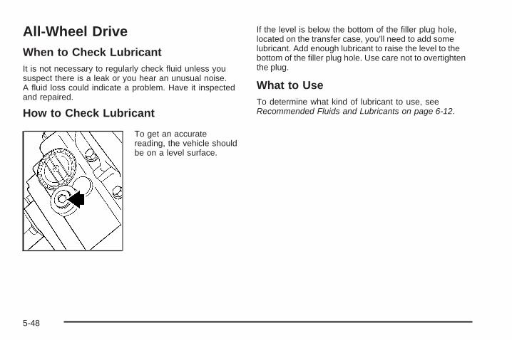
All-Wheel DriveWhen to Check LubricantIt is not necessary to regularly check fluid unless yoususpect there is a leak or you hear an unusual noise.A fluid loss could indicate a problem. Have it inspectedand repaired.
How to Check Lubricant
To get an accuratereading, the vehicle shouldbe on a level surface.
If the level is below the bottom of the filler plug hole,located on the transfer case, you’ll need to add somelubricant. Add enough lubricant to raise the level to thebottom of the filler plug hole. Use care not to overtightenthe plug.
What to UseTo determine what kind of lubricant to use, seeRecommended Fluids and Lubricants on page 6-12.
5-48
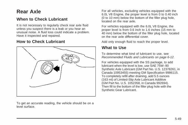
Rear AxleWhen to Check LubricantIt is not necessary to regularly check rear axle fluidunless you suspect there is a leak or you hear anunusual noise. A fluid loss could indicate a problem.Have it inspected and repaired.
How to Check Lubricant
To get an accurate reading, the vehicle should be on alevel surface.
For all vehicles, excluding vehicles equipped with the6.0L V8 Engine, the proper level is from 0 to 0.40 inch(0 to 10 mm) below the bottom of the filler plug hole,located on the rear axle.
For vehicles equipped with the 6.0L V8 Engine, theproper level is from 0.6 inch to 1.6 inches (15 mm to40 mm) below the bottom of the filler plug hole, locatedon the rear axle differential cover.
Add only enough fluid to reach the proper level.
What to UseTo determine what kind of lubricant to use, seeRecommended Fluids and Lubricants on page 6-12.
For vehicles equipped with the SS package, to addlubricant when the level is low, use SAE 75W–90Synthetic Axle Lubricant (GM Part No. U.S. 12378261, inCanada 10953455) meeting GM Specification 9986115.To completely refill after draining, add 5.5 ounces(163 ml) of Limited-Slip Axle Lubricant Additive(GM Part No. U.S. 1052358, in Canada 992694).Then fill to the bottom of the filler plug hole with theSynthetic Gear Lubricant.
5-49

Four-Wheel DriveTransfer Case
When to Check LubricantIt is not necessary to regularly check fluid unless yoususpect there is a leak or you hear an unusual noise.A fluid loss could indicate a problem. Have it inspectedand repaired.
How to Check Lubricant
To get an accuratereading, the vehicle shouldbe on a level surface.
If the level is below the bottom of the filler plug hole,you will need to add some lubricant. Add enoughlubricant to raise the level to the bottom of the fillerplug hole. Use care not to overtighten the plug.
What to UseTo determine what kind of lubricant to use, seeRecommended Fluids and Lubricants on page 6-12.
5-50

Front AxleWhen to Check LubricantIt is not necessary to regularly check front axle fluidunless you suspect there is a leak or you hear anunusual noise. A fluid loss could indicate a problem.Have it inspected and repaired.
How to Check Lubricant
To get an accurate reading, the vehicle should be on alevel surface.
If the level is below the bottom of the filler plug hole,located on the front axle, you may need to addsome lubricant.
When the differential is cold, add enough lubricantto raise the level to 0.50 inch (12 mm) below the fillerplug hole.
When the differential is at operating temperature(warm), add enough lubricant to raise the level to thebottom of the filler plug hole.
What to UseTo determine what kind of lubricant to use, seeRecommended Fluids and Lubricants on page 6-12.
5-51
Headlamp AimingHeadlamp aim has been preset at the factory andshould need no further adjustment.
However, if your vehicle is damaged in a crash, theheadlamp aim may be affected. Aim adjustment to thelow-beam headlamps may be necessary if oncomingdrivers flash their high-beam headlamps at you(for vertical aim).
If the headlamps need to be re-aimed, it isrecommended that you take the vehicle to yourdealer/retailer for service.
Bulb ReplacementFor the proper type of replacement bulbs,see Replacement Bulbs on page 5-54.
For any bulb changing procedure not listed in thissection, contact your dealer/retailer.
Halogen Bulbs
{CAUTION:
Halogen bulbs have pressurized gas inside andcan burst if you drop or scratch the bulb. You orothers could be injured. Be sure to read and followthe instructions on the bulb package.
5-52

Taillamps and Turn Signal Lamps1. Open the liftgate. See Liftgate/Liftglass on
page 2-13.
2. Remove the twoscrews from thetaillamp assembly.
3. Pull the taillamp assembly away from the vehicle.
4. Unclip the wiring harness (A) and remove the threeretaining screws (B) from the socket plate.
5. Remove the socket plate.
6. Holding the socket, pull the bulb to release it fromthe socket.
7. Push the new bulb into the socket until it clicks.
8. Reinstall the socket and tighten the three screws.
9. Reconnect the wiring harness.
10. Reinstall the taillamp assembly by lining up thelocator pins with the retainers in the vehicle’s body.
11. Reinstall the two screws and tighten.
5-53

License Plate Lamp1. Remove the two screws holding the license plate
lamp lens.
2. Pull the lens away from the lamp assembly.
3. Pull the old bulb straight out from the bulb socket.
4. Push the new bulb into the socket until it clicks.
5. Replace the lamp assembly lens and tightenthe screws.
Replacement Bulbs
Exterior Lamp Bulb Number
License Plate Lamp W5W
Taillamps 3157
For replacement bulbs not listed here, contact yourdealer/retailer.
5-54

Windshield Wiper BladeReplacementWindshield wiper blades should be inspected for wearor cracking. See Scheduled Maintenance on page 6-4.
Allowing the wiper blade arm to touch the windshieldwhen no wiper blade is installed could damage thewindshield. Any damage that occurs would notbe covered by your warranty. Do not allow thewiper blade arm to touch the windshield.
1. To remove the old wiper blades, lift the wiper armuntil it locks into a vertical position.
A. Blade AssemblyB. Arm AssemblyC. Locking Tab
D. Blade PivotE. Hook SlotF. Arm Hook
2. Press down on the blade assembly pivot lockingtab. Pull down on the blade assembly to release itfrom the wiper arm hook.
3. Remove the insert from the blade assembly. Theinsert has two notches at one end that are lockedby the bottom claws of the blade assembly. At thenotched end, pull the insert from the blade assembly.
5-55

4. To install the new wiper insert, slide the insert (D),notched end last, into the end with two bladeclaws (A). Slide the insert all the way through theblade claws at the opposite end (B). The plasticcaps (C) will be forced off as the insert is fullyinserted.
5. Be sure that the notches are locked by the bottomclaws. Make sure that all other claws are properlylocked on both sides of the insert slots.
A. Claw in NotchB. Correct InstallationC. Incorrect Installation
6. Put the blade assembly pivot in the wiper armhook. Pull up until the pivot locking tab locks in thehook slot.
7. Carefully lower the wiper arm and blade assemblyonto the windshield.
5-56
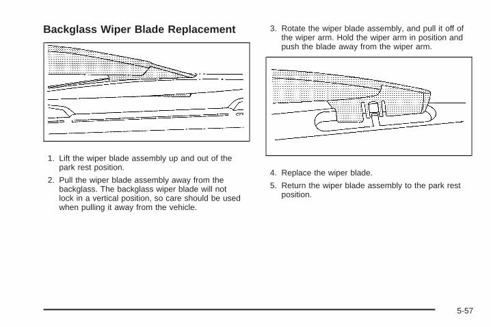
Backglass Wiper Blade Replacement
1. Lift the wiper blade assembly up and out of thepark rest position.
2. Pull the wiper blade assembly away from thebackglass. The backglass wiper blade will notlock in a vertical position, so care should be usedwhen pulling it away from the vehicle.
3. Rotate the wiper blade assembly, and pull it off ofthe wiper arm. Hold the wiper arm in position andpush the blade away from the wiper arm.
4. Replace the wiper blade.
5. Return the wiper blade assembly to the park restposition.
5-57

TiresYour new vehicle comes with high-quality tiresmade by a leading tire manufacturer. If you everhave questions about your tire warranty and whereto obtain service, see your vehicle Warranty bookletfor details. For additional information refer to the tiremanufacturer.
{CAUTION:
• Poorly maintained and improperly usedtires are dangerous.
• Overloading your tires can causeoverheating as a result of too muchflexing. You could have an air-out anda serious accident. See Loading theVehicle on page 4-33.
CAUTION: (Continued)
CAUTION: (Continued)
• Underinflated tires pose the same dangeras overloaded tires. The resulting accidentcould cause serious injury. Check all tiresfrequently to maintain the recommendedpressure. Tire pressure should bechecked when your tires are cold. SeeInflation - Tire Pressure on page 5-65.
• Overinflated tires are more likely to becut, punctured, or broken by a suddenimpact — such as when you hit a pothole.Keep tires at the recommended pressure.
• Worn, old tires can cause accidents.If your tread is badly worn, or if your tireshave been damaged, replace them.
See High-Speed Operation on page 5-66 forinflation pressure adjustment for high speeddriving.
5-58
Low-Profile Performance TireIf your vehicle has P255/50R20 size tires, they areclassified as low-profile performance tires. Thesetires are designed for very responsive driving onwet or dry pavement. You may also notice moreroad noise with low-profile performance tires andthat they tend to wear faster.
Notice: If the vehicle has low-profile tires,they are more susceptible to damage from roadhazards or curb impact than standard profiletires. Tire and/or wheel assembly damage canoccur when coming into contact with roadhazards like, potholes, or sharp edged objects,or when sliding into a curb. The vehiclewarranty does not cover this type of damage.Keep tires set to the correct inflation pressureand, when possible avoid contact with curbs,potholes, and other road hazards.
Winter TiresFor cold weather driving conditions you may prefer toget tires designed for snow or ice, if your vehicle hasP255/50R20 size tires. See your dealer for detailsregarding winter tire availability and proper tireselection. Also, see Buying New Tires on page 5-75.
If you choose to use winter tires:
• Use tires of the same brand and tread type on allfour wheel positions.
• Use only radial ply tires of the same size, loadrange, and speed rating as your original equipmenttires.
Winter tires with the same speed rating as your originalequipment tires may not be available for H, V, W, Yand ZR speed rated tires. If you choose winter tires witha lower speed rating, never exceed the tire’s maximumspeed capability.
5-59
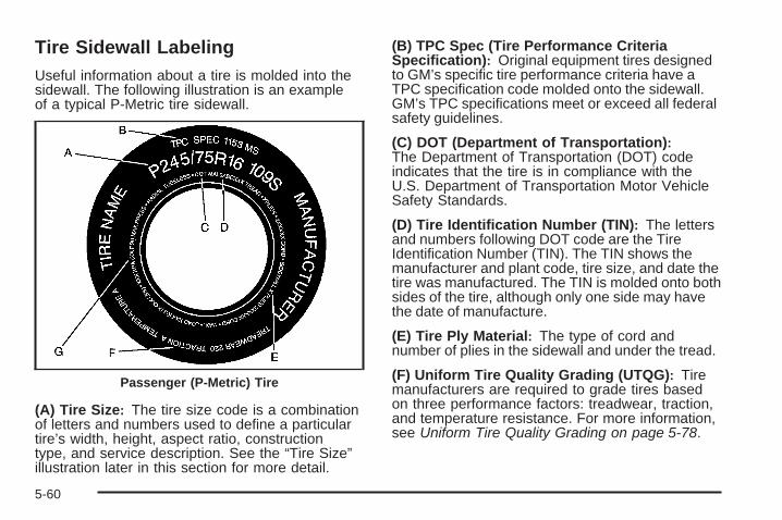
Tire Sidewall LabelingUseful information about a tire is molded into thesidewall. The following illustration is an exampleof a typical P-Metric tire sidewall.
(A) Tire Size: The tire size code is a combinationof letters and numbers used to define a particulartire’s width, height, aspect ratio, constructiontype, and service description. See the “Tire Size”illustration later in this section for more detail.
(B) TPC Spec (Tire Performance CriteriaSpecification): Original equipment tires designedto GM’s specific tire performance criteria have aTPC specification code molded onto the sidewall.GM’s TPC specifications meet or exceed all federalsafety guidelines.
(C) DOT (Department of Transportation):The Department of Transportation (DOT) codeindicates that the tire is in compliance with theU.S. Department of Transportation Motor VehicleSafety Standards.
(D) Tire Identification Number (TIN): The lettersand numbers following DOT code are the TireIdentification Number (TIN). The TIN shows themanufacturer and plant code, tire size, and date thetire was manufactured. The TIN is molded onto bothsides of the tire, although only one side may havethe date of manufacture.
(E) Tire Ply Material: The type of cord andnumber of plies in the sidewall and under the tread.
(F) Uniform Tire Quality Grading (UTQG): Tiremanufacturers are required to grade tires basedon three performance factors: treadwear, traction,and temperature resistance. For more information,see Uniform Tire Quality Grading on page 5-78.
Passenger (P-Metric) Tire
5-60
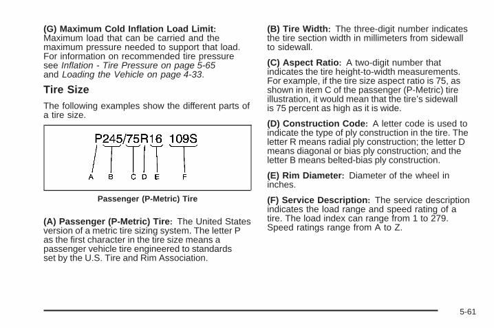
(G) Maximum Cold Inflation Load Limit:Maximum load that can be carried and themaximum pressure needed to support that load.For information on recommended tire pressuresee Inflation - Tire Pressure on page 5-65and Loading the Vehicle on page 4-33.
Tire SizeThe following examples show the different parts ofa tire size.
(A) Passenger (P-Metric) Tire: The United Statesversion of a metric tire sizing system. The letter Pas the first character in the tire size means apassenger vehicle tire engineered to standardsset by the U.S. Tire and Rim Association.
(B) Tire Width: The three-digit number indicatesthe tire section width in millimeters from sidewallto sidewall.
(C) Aspect Ratio: A two-digit number thatindicates the tire height-to-width measurements.For example, if the tire size aspect ratio is 75, asshown in item C of the passenger (P-Metric) tireillustration, it would mean that the tire’s sidewallis 75 percent as high as it is wide.
(D) Construction Code: A letter code is used toindicate the type of ply construction in the tire. Theletter R means radial ply construction; the letter Dmeans diagonal or bias ply construction; and theletter B means belted-bias ply construction.
(E) Rim Diameter: Diameter of the wheel ininches.
(F) Service Description: The service descriptionindicates the load range and speed rating of atire. The load index can range from 1 to 279.Speed ratings range from A to Z.
Passenger (P-Metric) Tire
5-61

Tire Terminology and Definitions
Air Pressure: The amount of air inside thetire pressing outward on each square inch ofthe tire. Air pressure is expressed in poundsper square inch (psi) or kilopascal (kPa).
Accessory Weight: This means the combinedweight of optional accessories. Some examples ofoptional accessories are, automatic transmission,power steering, power brakes, power windows,power seats, and air conditioning.
Aspect Ratio: The relationship of a tire’s heightto its width.
Belt: A rubber coated layer of cords that islocated between the plies and the tread. Cordsmay be made from steel or other reinforcingmaterials.
Bead: The tire bead contains steel wires wrappedby steel cords that hold the tire onto the rim.
Bias Ply Tire: A pneumatic tire in which the pliesare laid at alternate angles less than 90 degreesto the centerline of the tread.
Cold Tire Pressure: The amount of air pressurein a tire, measured in pounds per square inch (psi)or kilopascals (kPa) before a tire has built up heatfrom driving. See Inflation - Tire Pressure onpage 5-65.
Curb Weight: The weight of a motor vehicle withstandard and optional equipment including themaximum capacity of fuel, oil, and coolant,but without passengers and cargo.
DOT Markings: A code molded into the sidewallof a tire signifying that the tire is in compliancewith the U.S. Department of Transportation (DOT)motor vehicle safety standards. The DOT codeincludes the Tire Identification Number (TIN), analphanumeric designator which can also identify thetire manufacturer, production plant, brand, and dateof production.
GVWR: Gross Vehicle Weight Rating.See Loading the Vehicle on page 4-33.
GAWR FRT: Gross Axle Weight Rating for thefront axle. See Loading the Vehicle on page 4-33.
GAWR RR: Gross Axle Weight Rating for therear axle. See Loading the Vehicle on page 4-33.
5-62

Intended Outboard Sidewall: The side of anasymmetrical tire, that must always face outwardwhen mounted on a vehicle.
Kilopascal (kPa): The metric unit for air pressure.
Light Truck (LT-Metric) Tire: A tire used onlight duty trucks and some multipurpose passengervehicles.
Load Index: An assigned number rangingfrom 1 to 279 that corresponds to the load carryingcapacity of a tire.
Maximum Inflation Pressure: The maximumair pressure to which a cold tire can be inflated.The maximum air pressure is molded onto thesidewall.
Maximum Load Rating: The load rating for a tireat the maximum permissible inflation pressurefor that tire.
Maximum Loaded Vehicle Weight: The sum ofcurb weight, accessory weight, vehicle capacityweight, and production options weight.
Normal Occupant Weight: The number ofoccupants a vehicle is designed to seat multipliedby 150 lbs (68 kg). See Loading the Vehicle onpage 4-33.
Occupant Distribution: Designated seatingpositions.
Outward Facing Sidewall: The side of anasymmetrical tire that has a particular side thatfaces outward when mounted on a vehicle.The side of the tire that contains a whitewall,bears white lettering, or bears manufacturer,brand, and/or model name molding that is higheror deeper than the same moldings on the othersidewall of the tire.
Passenger (P-Metric) Tire: A tire used onpassenger cars and some light duty trucks andmultipurpose vehicles.
Recommended Inflation Pressure: Vehiclemanufacturer’s recommended tire inflation pressureas shown on the tire placard. See Inflation - TirePressure on page 5-65 and Loading the Vehicleon page 4-33.
5-63
Radial Ply Tire: A pneumatic tire in which theply cords that extend to the beads are laid at90 degrees to the centerline of the tread.
Rim: A metal support for a tire and upon whichthe tire beads are seated.
Sidewall: The portion of a tire between the treadand the bead.
Speed Rating: An alphanumeric code assigned toa tire indicating the maximum speed at which atire can operate.
Traction: The friction between the tire and theroad surface. The amount of grip provided.
Tread: The portion of a tire that comes intocontact with the road.
Treadwear Indicators: Narrow bands, sometimescalled wear bars, that show across the tread ofa tire when only 1/16 inch (1.6 mm) of treadremains. See When It Is Time for New Tireson page 5-74.
UTQGS (Uniform Tire Quality GradingStandards): A tire information system thatprovides consumers with ratings for a tire’straction, temperature, and treadwear. Ratings aredetermined by tire manufacturers using governmenttesting procedures. The ratings are molded intothe sidewall of the tire. See Uniform Tire QualityGrading on page 5-78.
Vehicle Capacity Weight: The number ofdesignated seating positions multiplied by 150 lbs(68 kg) plus the rated cargo load. See Loadingthe Vehicle on page 4-33.
Vehicle Maximum Load on the Tire: Load onan individual tire due to curb weight, accessoryweight, occupant weight, and cargo weight.
Vehicle Placard: A label permanently attached toa vehicle showing the vehicle’s capacity weight andthe original equipment tire size and recommendedinflation pressure. See “Tire and LoadingInformation Label” under Loading the Vehicle onpage 4-33.
5-64

Inflation - Tire PressureTires need the correct amount of air pressure tooperate effectively.
Notice: Do not let anyone tell you thatunder-inflation or over-inflation is all right.It is not. If your tires do not have enough air(under-inflation), you can get the following:• Too much flexing• Too much heat• Tire overloading• Premature or irregular wear• Poor handling• Reduced fuel economy
If your tires have too much air (over-inflation),you can get the following:• Unusual wear• Poor handling• Rough ride• Needless damage from road hazards
A vehicle specific Tire and Loading Informationlabel is attached to your vehicle. This label showsyour vehicle’s original equipment tires and thecorrect inflation pressures for your tires when theyare cold. The recommended cold tire inflationpressure, shown on the label, is the minimumamount of air pressure needed to support yourvehicle’s maximum load carrying capacity.
For additional information regarding how muchweight your vehicle can carry, and an example ofthe Tire and Loading Information label, see Loadingthe Vehicle on page 4-33. How you load yourvehicle affects vehicle handling and ride comfort.Never load your vehicle with more weight than itwas designed to carry.
When to CheckCheck your tires once a month or more.
Do not forget to check the pressure of the sparetire, if the vehicle has one. See Spare Tire onpage 5-109 for additional information.
5-65

How to CheckUse a good quality pocket-type gage to check tirepressure. You cannot tell if your tires are properlyinflated simply by looking at them. Radial tiresmay look properly inflated even when they areunderinflated. Check the tire’s inflation pressurewhen the tires are cold. Cold means your vehiclehas been sitting for at least three hours or drivenno more than 1 mile (1.6 km).
Remove the valve cap from the tire valve stem.Press the tire gage firmly onto the valve toget a pressure measurement. If the cold tireinflation pressure matches the recommendedpressure on the Tire and Loading Informationlabel, no further adjustment is necessary. If thepressure is low, add air until you reach therecommended amount.
If you overfill the tire, release air by pushing onthe metal stem in the center of the tire valve.Recheck the tire pressure with the tire gage.
Be sure to put the valve caps back on the valvestems. They help prevent leaks by keeping out dirtand moisture.
High-Speed Operation
{CAUTION:
Driving at high speeds, 100 mph (160 km/h) orhigher, puts an additional strain on tires. Sustainedhigh-speed driving causes excessive heat build upand can cause sudden tire failure. You could havea crash and you or others could be killed. Somehigh-speed rated tires require inflation pressureadjustment for high speed operation. When speedlimits and road conditions are such that a vehiclecan be driven at high speeds, make sure the tiresare rated for high speed operation, in excellentcondition, and set to the correct cold tire inflationpressure for the vehicle load.
5-66
If your vehicle has P255/50R20 104V size tires installedon the rear axle, they will require inflation pressureadjustment when driving your vehicle at speeds above99 mph (160 km/h). Set the cold inflation pressure, for therear tires only, to the maximum inflation pressure shownon the tire sidewall, or 38 psi (262 kPa), whichever islower. See the example following. When you end thishigh-speed driving, return the tires to the cold tire inflationpressure shown on the Tire and Loading Informationlabel. See Loading the Vehicle on page 4-33.
Example:
You will find the maximum load and inflation pressuremolded on the tire’s sidewall, in small letters, nearthe rim flange. It will read something like this: Maximumload 690 kg (1521 lbs) 300 kPa (44 psi) Max. Press.
For this example, you would set the inflation pressure forhigh-speed driving at 38 psi (262 kPa).
The inflation pressure for the front tires should be set tothe cold tire inflation pressure shown on the Tire andLoading Information label.
Racing or other competitive driving may affect thewarranty coverage of your vehicle. See your warrantybooklet for more information.
Tire Pressure Monitor SystemThe Tire Pressure Monitor System (TPMS) uses radioand sensor technology to check tire pressure levels.The TPMS sensors monitor the air pressure inyour vehicle’s tires and transmit tire pressure readingsto a receiver located in the vehicle.
Each tire, including the spare (if provided), should bechecked monthly when cold and inflated to the inflationpressure recommended by the vehicle manufactureron the vehicle placard or tire inflation pressure label.(If your vehicle has tires of a different size than thesize indicated on the vehicle placard or tire inflationpressure label, you should determine the propertire inflation pressure for those tires.)
As an added safety feature, your vehicle has beenequipped with a tire pressure monitoring system (TPMS)that illuminates a low tire pressure telltale when oneor more of your tires is significantly under-inflated.
Accordingly, when the low tire pressure telltaleilluminates, you should stop and check your tiresas soon as possible, and inflate them to the properpressure. Driving on a significantly under-inflatedtire causes the tire to overheat and can lead to tirefailure. Under-inflation also reduces fuel efficiencyand tire tread life, and may affect the vehicle’shandling and stopping ability.
5-67
Please note that the TPMS is not a substitute for propertire maintenance, and it is the driver’s responsibility tomaintain correct tire pressure, even if under-inflationhas not reached the level to trigger illumination ofthe TPMS low tire pressure telltale.
Your vehicle has also been equipped with a TPMSmalfunction indicator to indicate when the system isnot operating properly. The TPMS malfunction indicatoris combined with the low tire pressure telltale. Whenthe system detects a malfunction, the telltale will flashfor approximately one minute and then remaincontinuously illuminated. This sequence will continueupon subsequent vehicle start-ups as long as themalfunction exists.
When the malfunction indicator is illuminated, thesystem may not be able to detect or signal low tirepressure as intended. TPMS malfunctions may occurfor a variety of reasons, including the installation ofreplacement or alternate tires or wheels on the vehiclethat prevent the TPMS from functioning properly. Alwayscheck the TPMS malfunction telltale after replacing oneor more tires or wheels on your vehicle to ensure thatthe replacement or alternate tires and wheels allow theTPMS to continue to function properly.
See Tire Pressure Monitor Operation on page 5-69 foradditional information.
Federal CommunicationsCommission (FCC) andIndustry and Science CanadaThe Tire Pressure Monitor System (TPMS) operateson a radio frequency and complies with Part 15 ofthe FCC Rules. Operation is subject to the followingtwo conditions:
1. This device may not cause harmful interference.
2. This device must accept any interference received,including interference that may cause undesiredoperation.
The TPMS operates on a radio frequency and complieswith RSS-210 of Industry and Science Canada.Operation is subject to the following two conditions:
1. This device may not cause interference.
2. This device must accept any interference received,including interference that may cause undesiredoperation of the device.
Changes or modifications to this system by other thanan authorized service facility could void authorization touse this equipment.
5-68

Tire Pressure Monitor OperationThis vehicle may have a Tire Pressure Monitor System(TPMS). The TPMS is designed to warn the driver whena low tire pressure condition exists. TPMS sensors aremounted onto each tire and wheel assembly, excludingthe spare tire and wheel assembly, if the vehicle hasone. The TPMS sensors monitor the air pressure in thevehicle’s tires and transmit the tire pressure readings toa receiver located in the vehicle.
The TPMS is designed to alert the driver if a low tirepressure condition exists. If your vehicle has the DriverInformation Center (DIC) steering wheel control buttons,tire pressure levels may also be checked through theDIC. See “Tire Pressures” under DIC Operation andDisplays on page 3-48.
When a low tire pressurecondition is detected, theTPMS illuminates the lowtire pressure warning lightlocated on the instrumentpanel cluster.
At the same time a message to check the pressure ina specific tire appears on the Driver Information Center(DIC) display. The low tire pressure warning light and theDIC warning message come on at each ignition cycleuntil the tires are inflated to the correct inflation pressure.Using the DIC, tire pressure levels can be viewed by thedriver. For additional information and details about theDIC operation and displays see DIC Operation andDisplays on page 3-48 and DIC Warnings and Messageson page 3-51.
The low tire pressure warning light may come on incool weather when the vehicle is first started, and thenturn off as you start to drive. This could be an earlyindicator that the air pressure in the tire(s) is low andneeds to be inflated to the proper pressure.
A Tire and Loading Information label, attached toyour vehicle, shows the size of your vehicle’s originalequipment tires and the correct inflation pressure foryour vehicle’s tires when they are cold. See Loading theVehicle on page 4-33, for an example of the Tire andLoading Information label and its location on your vehicle.Also see Inflation - Tire Pressure on page 5-65.
5-69
Your vehicle’s TPMS can alert you about a low tirepressure condition but it does not replace normal tiremaintenance. See Tire Inspection and Rotation onpage 5-73 and Tires on page 5-58.
Notice: Using non-approved tire sealants coulddamage the Tire Pressure Monitor System (TPMS)sensors. TPMS sensor damage caused by usingan incorrect tire sealant is not covered by thevehicle warranty. Always use the GM approvedtire sealant available through your dealer/retailer.
Factory-installed Tire Inflator Kits use a GM approvedliquid tire sealant. Using non-approved tire sealantscould damage the TPMS sensors. See Tire Sealant andCompressor Kit for information regarding the inflatorkit materials and instructions.
TPMS Malfunction Light and MessageThe TPMS will not function properly if one or more ofthe TPMS sensors are missing or inoperable. When thesystem detects a malfunction, the low tire warning lightflashes for about one minute and then stays on for theremainder of the ignition cycle. A DIC warning messageis also displayed. The low tire warning light and DICwarning message come on at each ignition cycle untilthe problem is corrected. Some of the conditions thatcan cause the malfunction light and DIC message tocome on are:
• One of the road tires has been replaced with thespare tire, if the vehicle has one. The spare tire doesnot have a TPMS sensor. The TPMS malfunctionlight and DIC message should go off once youre-install the road tire containing the TPMS sensor.
• The TPMS sensor matching process was started butnot completed or not completed successfully afterrotating the vehicle’s tires. The DIC message andTPMS malfunction light should go off once the TPMSsensor matching process is performed successfully.See “TPMS Sensor Matching Process” later in thissection.
5-70
• One or more TPMS sensors are missing ordamaged. The DIC message and the TPMSmalfunction light should go off when the TPMSsensors are installed and the sensor matchingprocess is performed successfully. See yourdealer/retailer for service.
• Replacement tires or wheels do not match yourvehicle’s original equipment tires or wheels. Tiresand wheels other than those recommended for yourvehicle could prevent the TPMS from functioningproperly. See Buying New Tires on page 5-75.
• Operating electronic devices or being near facilitiesusing radio wave frequencies similar to the TPMScould cause the TPMS sensors to malfunction.
If the TPMS is not functioning it cannot detect orsignal a low tire condition. See your dealer/retailerfor service if the TPMS malfunction light and DICmessage come on and stay on.
TPMS Sensor Matching ProcessEach TPMS sensor has a unique identification code.Any time you rotate your vehicle’s tires or replace oneor more of the TPMS sensors, the identification codeswill need to be matched to the new tire/wheel position.The sensors are matched to the tire/wheel positions inthe following order: driver side front tire, passenger sidefront tire, passenger side rear tire, and driver side rear tireusing a TPMS diagnostic tool. See your dealer/retailer forservice.
The TPMS sensors can also be matched to eachtire/wheel position by increasing or decreasing the tire’sair pressure. If increasing the tire’s air pressure, donot exceed the maximum inflation pressure indicatedon the tire’s sidewall.
To decrease air-pressure out of a tire you can use thepointed end of the valve cap, a pencil-style air pressuregage, or a key.
5-71
You have two minutes to match the first tire/wheelposition, and five minutes overall to match all fourtire/wheel positions. If it takes longer than two minutes, tomatch the first tire and wheel, or more than five minutesto match all four tire and wheel positions the matchingprocess stops and you need to start over.
The TPMS sensor matching process is outlined below:
1. Set the parking brake.
2. Turn the ignition switch to ON/RUN with theengine off.
3. Turn the headlamp control from off to parking lampsfour times within three seconds. A double horn chirpwill sound and the TPMS low tire warning light willbegin to flash. The double horn chirp and flashingTPMS warning light indicate that the TPMS matchingprocess has started. The TPMS warning light shouldcontinue flashing throughout the matchingprocedure.
4. Start with the driver side front tire.
5. Remove the valve cap from the valve cap stem.Activate the TPMS sensor by increasing ordecreasing the tire’s air pressure for 10 seconds,then stop and listen for a single horn chirp.
The single horn chirp should sound within15 seconds, confirming that the sensor identificationcode has been matched to this tire and wheelposition. If you do not hear the confirming singlehorn chirp, you will need to start over withstep number one.
6. Proceed to the passenger side front tire, and repeatthe procedure in Step 5.
7. Proceed to the passenger side rear tire, and repeatthe procedure in Step 5.
8. Proceed to the driver side rear tire, and repeat theprocedure in Step 5.
9. After hearing the confirming horn chirp for thedriver’s side rear tire, check to see if the TPMSwarning light is still flashing. If yes, turn the ignitionswitch to LOCK/OFF to exit the sensor matchingprocess. If the TPMS warning light is not flashing,the five minute time limit has passed and youwill need to start the process over beginning withStep 1.
10. Set all four tires to the recommended air pressurelevel as indicated on the Tire and LoadingInformation label.
11. Put the valve caps back on the valve stems.
5-72
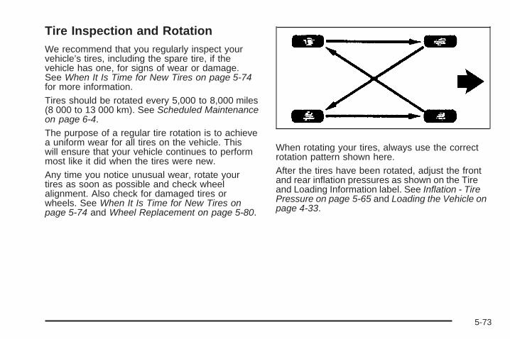
Tire Inspection and RotationWe recommend that you regularly inspect yourvehicle’s tires, including the spare tire, if thevehicle has one, for signs of wear or damage.See When It Is Time for New Tires on page 5-74for more information.
Tires should be rotated every 5,000 to 8,000 miles(8 000 to 13 000 km). See Scheduled Maintenanceon page 6-4.
The purpose of a regular tire rotation is to achievea uniform wear for all tires on the vehicle. Thiswill ensure that your vehicle continues to performmost like it did when the tires were new.
Any time you notice unusual wear, rotate yourtires as soon as possible and check wheelalignment. Also check for damaged tires orwheels. See When It Is Time for New Tires onpage 5-74 and Wheel Replacement on page 5-80.
When rotating your tires, always use the correctrotation pattern shown here.
After the tires have been rotated, adjust the frontand rear inflation pressures as shown on the Tireand Loading Information label. See Inflation - TirePressure on page 5-65 and Loading the Vehicle onpage 4-33.
5-73
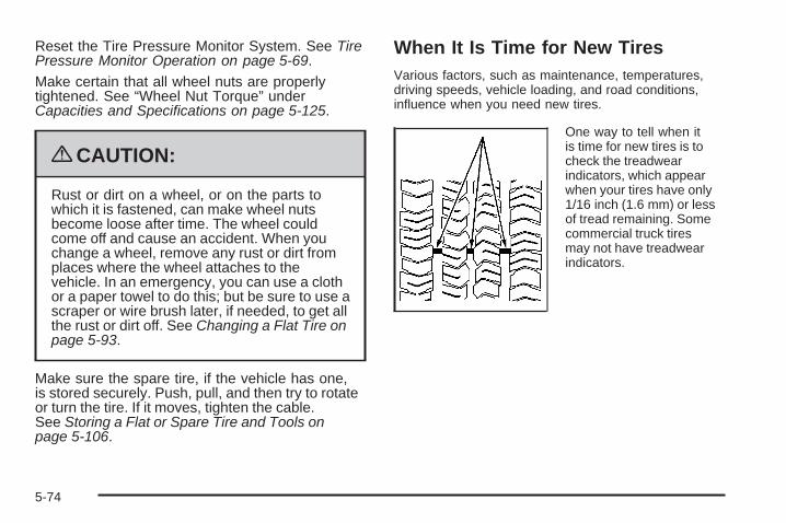
Reset the Tire Pressure Monitor System. See TirePressure Monitor Operation on page 5-69.
Make certain that all wheel nuts are properlytightened. See “Wheel Nut Torque” underCapacities and Specifications on page 5-125.
{CAUTION:
Rust or dirt on a wheel, or on the parts towhich it is fastened, can make wheel nutsbecome loose after time. The wheel couldcome off and cause an accident. When youchange a wheel, remove any rust or dirt fromplaces where the wheel attaches to thevehicle. In an emergency, you can use a clothor a paper towel to do this; but be sure to use ascraper or wire brush later, if needed, to get allthe rust or dirt off. See Changing a Flat Tire onpage 5-93.
Make sure the spare tire, if the vehicle has one,is stored securely. Push, pull, and then try to rotateor turn the tire. If it moves, tighten the cable.See Storing a Flat or Spare Tire and Tools onpage 5-106.
When It Is Time for New TiresVarious factors, such as maintenance, temperatures,driving speeds, vehicle loading, and road conditions,influence when you need new tires.
One way to tell when itis time for new tires is tocheck the treadwearindicators, which appearwhen your tires have only1/16 inch (1.6 mm) or lessof tread remaining. Somecommercial truck tiresmay not have treadwearindicators.
5-74
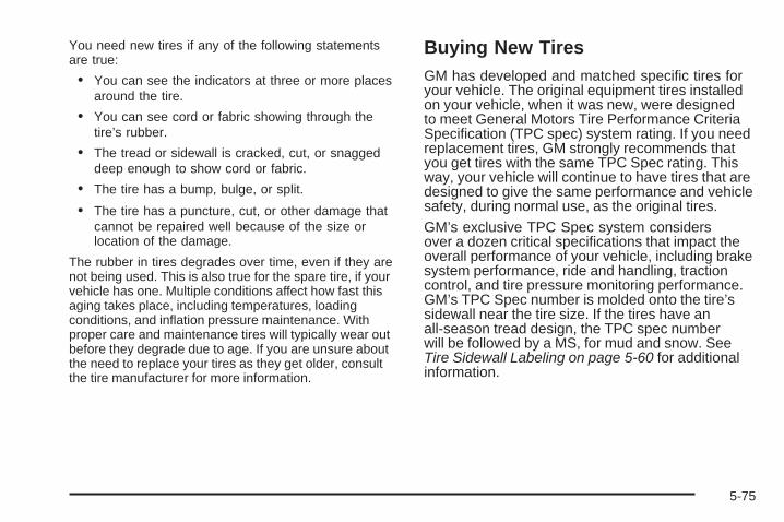
You need new tires if any of the following statementsare true:
• You can see the indicators at three or more placesaround the tire.
• You can see cord or fabric showing through thetire’s rubber.
• The tread or sidewall is cracked, cut, or snaggeddeep enough to show cord or fabric.
• The tire has a bump, bulge, or split.
• The tire has a puncture, cut, or other damage thatcannot be repaired well because of the size orlocation of the damage.
The rubber in tires degrades over time, even if they arenot being used. This is also true for the spare tire, if yourvehicle has one. Multiple conditions affect how fast thisaging takes place, including temperatures, loadingconditions, and inflation pressure maintenance. Withproper care and maintenance tires will typically wear outbefore they degrade due to age. If you are unsure aboutthe need to replace your tires as they get older, consultthe tire manufacturer for more information.
Buying New TiresGM has developed and matched specific tires foryour vehicle. The original equipment tires installedon your vehicle, when it was new, were designedto meet General Motors Tire Performance CriteriaSpecification (TPC spec) system rating. If you needreplacement tires, GM strongly recommends thatyou get tires with the same TPC Spec rating. Thisway, your vehicle will continue to have tires that aredesigned to give the same performance and vehiclesafety, during normal use, as the original tires.
GM’s exclusive TPC Spec system considersover a dozen critical specifications that impact theoverall performance of your vehicle, including brakesystem performance, ride and handling, tractioncontrol, and tire pressure monitoring performance.GM’s TPC Spec number is molded onto the tire’ssidewall near the tire size. If the tires have anall-season tread design, the TPC spec numberwill be followed by a MS, for mud and snow. SeeTire Sidewall Labeling on page 5-60 for additionalinformation.
5-75

GM recommends replacing tires in sets of four.This is because uniform tread depth on all tireswill help keep your vehicle performing most likeit did when the tires were new. Replacing lessthan a full set of tires can affect the brakingand handling performance of your vehicle.See Tire Inspection and Rotation on page 5-73for information on proper tire rotation.
{CAUTION:
Mixing tires could cause you to lose controlwhile driving. If you mix tires of differentsizes, brands, or types (radial and bias-beltedtires) the vehicle may not handle properly,and you could have a crash. Using tires ofdifferent sizes, brands, or types may alsocause damage to your vehicle. Be sure touse the correct size, brand, and type oftires on your vehicle’s wheels.
{CAUTION:
If you use bias-ply tires on the vehicle, thewheel rim flanges could develop cracks aftermany miles of driving. A tire and/or wheelcould fail suddenly, causing a crash. Useonly radial-ply tires with the wheels on thevehicle.
If you must replace your vehicle’s tires with thosethat do not have a TPC Spec number, make surethey are the same size, load range, speed rating,and construction type (radial and bias-belted tires)as your vehicle’s original tires.
Vehicles equipped with a tire pressure monitoringsystem may give an inaccurate low-pressurewarning if non-TPC spec rated tires are installedon your vehicle. Non-TPC Spec rated tires maygive a low-pressure warning that is higher or lowerthan the proper warning level you would get withTPC Spec rated tires. See Tire Pressure MonitorSystem on page 5-67.
5-76

Your vehicle’s original equipment tires are listedon the Tire and Loading Information Label.See Loading the Vehicle on page 4-33, for moreinformation about the Tire and Loading InformationLabel and its location on your vehicle.
Different Size Tires and WheelsIf you add wheels or tires that are a different size thanyour original equipment wheels and tires, this could affectthe way your vehicle performs, including its braking, rideand handling characteristics, stability, and resistanceto rollover. Additionally, if your vehicle has electronicsystems such as anti-lock brakes, rollover airbags,traction control, and electronic stability control, theperformance of these systems can be affected.
{CAUTION:
If you add different sized wheels, your vehicle maynot provide an acceptable level of performance andsafety if tires not recommended for those wheelsare selected. You may increase the chance that youwill crash and suffer serious injury. Only use GMspecific wheel and tire systems developed for yourvehicle, and have them properly installed by a GMcertified technician.
See Buying New Tires on page 5-75 and Accessoriesand Modifications on page 5-3 for additional information.
5-77
Uniform Tire Quality GradingQuality grades can be found where applicable onthe tire sidewall between tread shoulder andmaximum section width. For example:
Treadwear 200 Traction AATemperature AThe following information relates to thesystem developed by the United States NationalHighway Traffic Safety Administration (NHTSA),which grades tires by treadwear, traction, andtemperature performance. This applies only tovehicles sold in the United States. The grades aremolded on the sidewalls of most passenger cartires. The Uniform Tire Quality Grading (UTQG)system does not apply to deep tread, winter-typesnow tires, space-saver, or temporary usespare tires, tires with nominal rim diametersof 10 to 12 inches (25 to 30 cm), or to somelimited-production tires.
While the tires available on General Motorspassenger cars and light trucks may vary withrespect to these grades, they must also conformto federal safety requirements and additionalGeneral Motors Tire Performance Criteria (TPC)standards.
TreadwearThe treadwear grade is a comparative ratingbased on the wear rate of the tire when testedunder controlled conditions on a specifiedgovernment test course. For example, a tiregraded 150 would wear one and a half (1.5) timesas well on the government course as a tiregraded 100. The relative performance of tiresdepends upon the actual conditions of their use,however, and may depart significantly from thenorm due to variations in driving habits, servicepractices, and differences in road characteristicsand climate.
5-78
Traction – AA, A, B, CThe traction grades, from highest to lowest, areAA, A, B, and C. Those grades represent the tire’sability to stop on wet pavement as measured undercontrolled conditions on specified government testsurfaces of asphalt and concrete. A tire marked Cmay have poor traction performance.
{WARNING:
The traction grade assigned to this tire isbased on straight-ahead braking tractiontests, and does not include acceleration,cornering, hydroplaning, or peak tractioncharacteristics.
Temperature – A, B, CThe temperature grades are A (the highest), B,and C, representing the tire’s resistance to thegeneration of heat and its ability to dissipate heatwhen tested under controlled conditions on aspecified indoor laboratory test wheel. Sustainedhigh temperature can cause the material of the tireto degenerate and reduce tire life, and excessivetemperature can lead to sudden tire failure. Thegrade C corresponds to a level of performancewhich all passenger car tires must meet under theFederal Motor Vehicle Safety Standard No. 109.Grades B and A represent higher levels ofperformance on the laboratory test wheel thanthe minimum required by law.
{WARNING:
The temperature grade for this tire isestablished for a tire that is properly inflatedand not overloaded. Excessive speed,underinflation, or excessive loading, eitherseparately or in combination, can causeheat buildup and possible tire failure.
5-79
Wheel Alignment and Tire BalanceThe tires and wheels on your vehicle were aligned andbalanced carefully at the factory to give you the longesttire life and best overall performance. Adjustments towheel alignment and tire balancing will not be necessaryon a regular basis. However, if you notice unusual tirewear or your vehicle pulling to one side or the other, thealignment might need to be checked. If you notice yourvehicle vibrating when driving on a smooth road, the tiresand wheels might need to be rebalanced. See yourdealer/retailer for proper diagnosis.
Wheel ReplacementReplace any wheel that is bent, cracked, or badly rustedor corroded. If wheel nuts keep coming loose, the wheel,wheel bolts, and wheel nuts should be replaced. If thewheel leaks air, replace it (except some aluminumwheels, which can sometimes be repaired). See yourdealer/retailer if any of these conditions exist.
Your dealer/retailer will know the kind of wheelyou need.
Each new wheel should have the same load-carryingcapacity, diameter, width, offset, and be mountedthe same way as the one it replaces.
If you need to replace any of your wheels, wheel bolts,wheel nuts, or Tire Pressure Monitor System (TPMS)sensors, replace them only with new GM originalequipment parts. This way, you will be sure to havethe right wheel, wheel bolts, wheel nuts, and TPMSsensors for your vehicle.
{CAUTION:
Using the wrong replacement wheels, wheel bolts,or wheel nuts on your vehicle can be dangerous.It could affect the braking and handling of yourvehicle, make your tires lose air and make youlose control. You could have a collision in whichyou or others could be injured. Always use thecorrect wheel, wheel bolts, and wheel nuts forreplacement.
5-80

Notice: The wrong wheel can also cause problemswith bearing life, brake cooling, speedometer orodometer calibration, headlamp aim, bumper height,vehicle ground clearance, and tire or tire chainclearance to the body and chassis.
See Changing a Flat Tire on page 5-93 for moreinformation.
Used Replacement Wheels
{CAUTION:
Putting a used wheel on the vehicle is dangerous.You cannot know how it has been used or howfar it has been driven. It could fail suddenly andcause a crash. If you have to replace a wheel,use a new GM original equipment wheel.
Tire Chains
{CAUTION:
Do not use tire chains. There is not enoughclearance. Tire chains used on a vehicle withoutthe proper amount of clearance can cause damageto the brakes, suspension, or other vehicle parts.The area damaged by the tire chains could causeyou to lose control of the vehicle and you or othersmay be injured in a crash. Use another type oftraction device only if its manufacturer recommendsit for use on the vehicle and tire size combinationand road conditions. Follow that manufacturer’sinstructions. To help avoid damage to the vehicle,drive slowly, re-adjust or remove the device if it iscontacting the vehicle, and do not spin the wheels.If you do find traction devices that will fit, installthem on the rear tires.
5-81
If a Tire Goes FlatIt is unusual for a tire to blowout while you are driving,especially if you maintain your vehicle’s tires properly.If air goes out of a tire, it is much more likely to leakout slowly. But if you should ever have a blowout, hereare a few tips about what to expect and what to do:
If a front tire fails, the flat tire creates a drag that pullsthe vehicle toward that side. Take your foot off theaccelerator pedal and grip the steering wheel firmly.Steer to maintain lane position, and then gently braketo a stop well out of the traffic lane.
A rear blowout, particularly on a curve, acts much likea skid and may require the same correction you woulduse in a skid. In any rear blowout remove your foot fromthe accelerator pedal. Get the vehicle under control bysteering the way you want the vehicle to go. It may bevery bumpy and noisy, but you can still steer. Gentlybrake to a stop, well off the road if possible.
{CAUTION:
Lifting a vehicle and getting under it to domaintenance or repairs is dangerous without theappropriate safety equipment and training. If a jackis provided with the vehicle, it is designed only forchanging a flat tire. If it is used for anything else,you or others could be badly injured or killed if thevehicle slips off the jack. If a jack is provided withthe vehicle, only use it for changing a flat tire.
This vehicle may come with a jack and spare tire or atire sealant and compressor kit. To use the jack andspare tire, see Changing a Flat Tire on page 5-93.To use the tire sealant and compressor kit, see TireSealant and Compressor Kit on page 5-83.
5-82
Tire Sealant and Compressor Kit
{CAUTION:
Idling a vehicle in an enclosed area with poorventilation is dangerous. Engine exhaust mayenter the vehicle. Engine exhaust contains CarbonMonoxide (CO) which cannot be seen or smelled.It can cause unconsciousness and even death.Never run the engine in an enclosed area thathas no fresh air ventilation. For more information,see Engine Exhaust on page 2-38.
{CAUTION:
Over-inflating a tire could cause the tire to ruptureand you or others could be injured. Be sure toread and follow the tire sealant and compressor kitinstructions and inflate the tire to its recommendedpressure. Do not exceed the recommendedpressure.
{CAUTION:
Storing the tire sealant and compressor kit orother equipment in the passenger compartment ofthe vehicle could cause injury. In a sudden stop orcollision, loose equipment could strike someone.Store the tire sealant and compressor kit in itsoriginal location.
If this vehicle has a tire sealant and compressor kit,there may not be a spare tire, tire changing equipment,and on some vehicles there may not be a place tostore a tire.
5-83
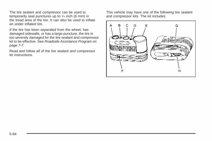
The tire sealant and compressor can be used totemporarily seal punctures up to 1⁄4 inch (6 mm) inthe tread area of the tire. It can also be used to inflatean under inflated tire.
If the tire has been separated from the wheel, hasdamaged sidewalls, or has a large puncture, the tire istoo severely damaged for the tire sealant and compressorkit to be effective. See Roadside Assistance Program onpage 7-7.
Read and follow all of the tire sealant and compressorkit instructions.
This vehicle may have one of the following tire sealantand compressor kits. The kit includes:
5-84
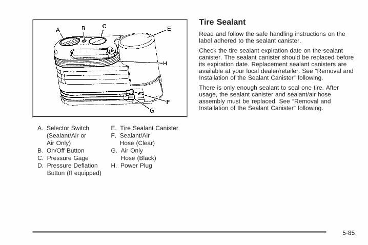
A. Selector Switch(Sealant/Air orAir Only)
B. On/Off ButtonC. Pressure GageD. Pressure Deflation
Button (If equipped)
E. Tire Sealant CanisterF. Sealant/Air
Hose (Clear)G. Air Only
Hose (Black)H. Power Plug
Tire SealantRead and follow the safe handling instructions on thelabel adhered to the sealant canister.
Check the tire sealant expiration date on the sealantcanister. The sealant canister should be replaced beforeits expiration date. Replacement sealant canisters areavailable at your local dealer/retailer. See “Removal andInstallation of the Sealant Canister” following.
There is only enough sealant to seal one tire. Afterusage, the sealant canister and sealant/air hoseassembly must be replaced. See “Removal andInstallation of the Sealant Canister” following.
5-85

Using the Tire Sealant and CompressorKit to Temporarily Seal and Inflate aPunctured TireFollow the directions closely for correct sealant usage.
When using the tire sealant and compressor kit duringcold temperatures, warm the kit in a heated environmentfor 5 minutes. This will help to inflate the tire faster.
Always do a safety check first. See If a Tire Goes Flaton page 5-82. Do not remove any objects that havepenetrated the tire.
1. Remove the tire sealant and compressor kit from itsstorage location. See Tire Sealant and CompressorKit Storage on page 5-92.
2. Unwrap the sealant/air hose (F) and the powerplug (H).
5-86

3. Place the kit on the ground.Make sure the tire valve stem is positioned close tothe ground so the hose will reach it.
4. Remove the valve stem cap from the flat tire byturning it counterclockwise.
5. Attach the sealant/air hose (F) onto the tire valvestem. Turn it clockwise until it is tight.
6. Plug the power plug (H) into the accessory poweroutlet in the vehicle. Unplug all items from otheraccessory power outlets. See Accessory PowerOutlet(s) on page 3-19.If the vehicle has an accessory power outlet, do notuse the cigarette lighter.If the vehicle only has a cigarette lighter, use thecigarette lighter.Do not pinch the power plug cord in the door orwindow.
7. Start the vehicle. The vehicle must be running whileusing the air compressor.
8. Turn the selector switch (A) counterclockwise to theSealant + Air position.
9. Press the on/off (B) button to turn the tire sealantand compressor kit on.The compressor will inject sealant and air intothe tire.The pressure gage (C) will initially show a highpressure while the compressor pushes the sealantinto the tire. Once the sealant is completely
dispersed into the tire, the pressure will quicklydrop and start to rise again as the tire inflateswith air only.
10. Inflate the tire to the recommended inflationpressure using the pressure gage (C).The recommended inflation pressure canbe found on the Tire and Loading Informationlabel. See Inflation - Tire Pressure on page 5-65.The pressure gage (C) may read higher than theactual tire pressure while the compressor is on.Turn the compressor off to get an accurate pressurereading. The compressor may be turned on/offuntil the correct pressure is reached.
Notice: If the recommended pressure cannot bereached after approximately 25 minutes, the vehicleshould not be driven farther. The tire is too severelydamaged and the tire sealant and compressor kitcannot inflate the tire. Remove the power plug fromthe accessory power outlet and unscrew the inflatinghose from the tire valve. See Roadside AssistanceProgram on page 7-7.11. Press the on/off button (B) to turn the tire sealant
and compressor kit off.The tire is not sealed and will continue to leakair until the vehicle is driven and the sealantis distributed in the tire, therefore, Steps 12 through18 must be done immediately after Step 11.Be careful while handling the tire sealant andcompressor kit as it could be warm after usage.
5-87
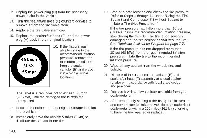
12. Unplug the power plug (H) from the accessorypower outlet in the vehicle.
13. Turn the sealant/air hose (F) counterclockwise toremove it from the tire valve stem.
14. Replace the tire valve stem cap.
15. Replace the sealant/air hose (F), and the powerplug (H) back in their original location.
16. If the flat tire wasable to inflate to therecommended inflationpressure, remove themaximum speed labelfrom the sealantcanister (E) and placeit in a highly visiblelocation.
The label is a reminder not to exceed 55 mph(90 km/h) until the damaged tire is repairedor replaced.
17. Return the equipment to its original storage locationin the vehicle.
18. Immediately drive the vehicle 5 miles (8 km) todistribute the sealant in the tire.
19. Stop at a safe location and check the tire pressure.Refer to Steps 1 through 11 under “Using the TireSealant and Compressor Kit without Sealant toInflate a Tire (Not Punctured).”If the tire pressure has fallen more than 10 psi(68 kPa) below the recommended inflation pressure,stop driving the vehicle. The tire is too severelydamaged and the tire sealant cannot seal the tire.See Roadside Assistance Program on page 7-7.If the tire pressure has not dropped more than10 psi (68 kPa) from the recommended inflationpressure, inflate the tire to the recommendedinflation pressure.
20. Wipe off any sealant from the wheel, tire, andvehicle.
21. Dispose of the used sealant canister (E) andsealant/air hose (F) assembly at a local dealer/retailer or in accordance with local state codesand practices.
22. Replace it with a new canister available from yourdealer/retailer.
23. After temporarily sealing a tire using the tire sealantand compressor kit, take the vehicle to an authorizeddealer/retailer within a 100 miles (161 km) of drivingto have the tire repaired or replaced.
5-88
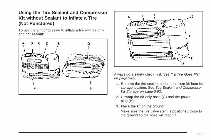
Using the Tire Sealant and CompressorKit without Sealant to Inflate a Tire(Not Punctured)To use the air compressor to inflate a tire with air onlyand not sealant:
Always do a safety check first. See If a Tire Goes Flaton page 5-82.
1. Remove the tire sealant and compressor kit from itsstorage location. See Tire Sealant and CompressorKit Storage on page 5-92.
2. Unwrap the air only hose (G) and the powerplug (H).
3. Place the kit on the ground.Make sure the tire valve stem is positioned close tothe ground so the hose will reach it.
5-89

4. Remove the tire valve stem cap from the flat tire byturning it counterclockwise.
5. Attach the air only hose (G) onto the tire valve stemby turning it clockwise until it is tight.
6. Plug the power plug (H) into the accessory poweroutlet in the vehicle. Unplug all items from otheraccessory power outlets. See Accessory PowerOutlet(s) on page 3-19.If the vehicle has an accessory power outlet, do notuse the cigarette lighter.If the vehicle only has a cigarette lighter, use thecigarette lighter.Do not pinch the power plug cord in the door orwindow.
7. Start the vehicle. The vehicle must be running whileusing the air compressor.
8. Turn the selector switch (A) clockwise to the AirOnly position.
9. Press the on/off (B) button to turn thecompressor on.The compressor will inflate the tire with air only.
10. Inflate the tire to the recommended inflationpressure using the pressure gage (C). Therecommended inflation pressure can be foundon the Tire and Loading Information label.See Inflation - Tire Pressure on page 5-65.The pressure gage (C) may read higher than theactual tire pressure while the compressor is on.Turn the compressor off to get an accurate reading.The compressor may be turned on/off until thecorrect pressure is reached.If you inflate the tire higher than the recommendedpressure you can adjust the excess pressureby pressing the pressure deflation button (D),if equipped, until the proper pressure readingis reached. This option is only functional whenusing the air only hose (G).
11. Press the on/off button (B) to turn the tire sealantand compressor kit off.Be careful while handling the tire sealant andcompressor kit as it could be warm after usage.
5-90
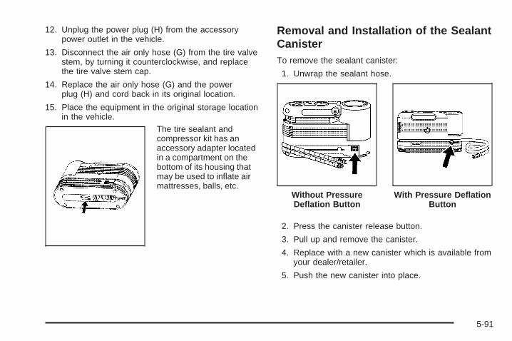
12. Unplug the power plug (H) from the accessorypower outlet in the vehicle.
13. Disconnect the air only hose (G) from the tire valvestem, by turning it counterclockwise, and replacethe tire valve stem cap.
14. Replace the air only hose (G) and the powerplug (H) and cord back in its original location.
15. Place the equipment in the original storage locationin the vehicle.
The tire sealant andcompressor kit has anaccessory adapter locatedin a compartment on thebottom of its housing thatmay be used to inflate airmattresses, balls, etc.
Removal and Installation of the SealantCanisterTo remove the sealant canister:
1. Unwrap the sealant hose.
2. Press the canister release button.
3. Pull up and remove the canister.
4. Replace with a new canister which is available fromyour dealer/retailer.
5. Push the new canister into place.
Without PressureDeflation Button
With Pressure DeflationButton
5-91
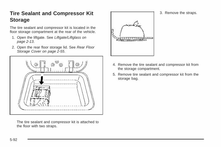
Tire Sealant and Compressor KitStorageThe tire sealant and compressor kit is located in thefloor storage compartment at the rear of the vehicle.
1. Open the liftgate. See Liftgate/Liftglass onpage 2-13.
2. Open the rear floor storage lid. See Rear FloorStorage Cover on page 2-55.
The tire sealant and compressor kit is attached tothe floor with two straps.
3. Remove the straps.
4. Remove the tire sealant and compressor kit fromthe storage compartment.
5. Remove tire sealant and compressor kit from thestorage bag.
5-92

Changing a Flat TireIf a tire goes flat, avoid further tire and wheel damageby driving slowly to a level place. Turn on the hazardwarning flashers. See Hazard Warning Flasherson page 3-6.
{CAUTION:
Changing a tire can be dangerous. The vehiclecan slip off the jack and roll over or fall on you orother people. You and they could be badly injuredor even killed. Find a level place to change yourtire. To help prevent the vehicle from moving:
1. Set the parking brake firmly.
2. Put the shift lever in P (Park).
3. If you have a four-wheel-drive vehicle,be sure the transfer case is in a drivegear — not in Neutral.
4. Turn off the engine and do not restart whilethe vehicle is raised.
CAUTION: (Continued)
CAUTION: (Continued)
5. Do not allow passengers to remain in thevehicle.
6. Put the wheel blocks at the front and rear ofthe tire farthest away from the one beingchanged. That would be the tire on the otherside, at the opposite end of the vehicle.
When the vehicle has a flat tire (B), use the followingexample as a guide to assist you in the placementof wheel blocks (A).
A. Wheel BlockB. Flat TireThe following information explains how to use the jackand change a tire.
5-93

Removing the Spare Tire and Tools
The jacking equipment needed to remove the spare tireis stored under the rear seat. To release the jack from itsholder, turn the knob on the jack counterclockwise tolower the jack head. See Rear Seat Operation onpage 1-11 for more information.
The tools you will be using include:
A. Wheel WrenchB. Wheel BlocksC. Extension(s)
(Socket End)
D. Handle (Jack End)E. Jack
5-94
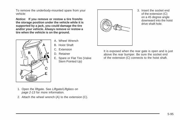
To remove the underbody-mounted spare from yourvehicle:
Notice: If you remove or restow a tire from/tothe storage position under the vehicle while it issupported by a jack, you could damage the tireand/or your vehicle. Always remove or restow atire when the vehicle is on the ground.
A. Wheel WrenchB. Hoist ShaftC. ExtensionD. RetainerE. Spare or Flat Tire (Valve
Stem Pointed Up)
1. Open the liftgate. See Liftgate/Liftglass onpage 2-13 for more information.
2. Attach the wheel wrench (A) to the extension (C).
3. Insert the socket endof the extension (C)on a 45 degree angledownward into the hoistdrive shaft hole.
It is exposed when the rear gate is open and is justabove the rear bumper. Be sure the socket endof the extension (C) connects to the hoist shaft.
5-95
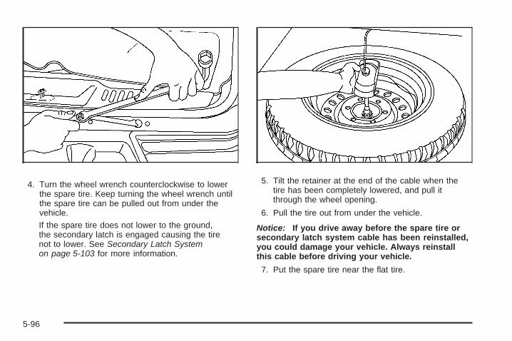
4. Turn the wheel wrench counterclockwise to lowerthe spare tire. Keep turning the wheel wrench untilthe spare tire can be pulled out from under thevehicle.If the spare tire does not lower to the ground,the secondary latch is engaged causing the tirenot to lower. See Secondary Latch Systemon page 5-103 for more information.
5. Tilt the retainer at the end of the cable when thetire has been completely lowered, and pull itthrough the wheel opening.
6. Pull the tire out from under the vehicle.
Notice: If you drive away before the spare tire orsecondary latch system cable has been reinstalled,you could damage your vehicle. Always reinstallthis cable before driving your vehicle.
7. Put the spare tire near the flat tire.
5-96
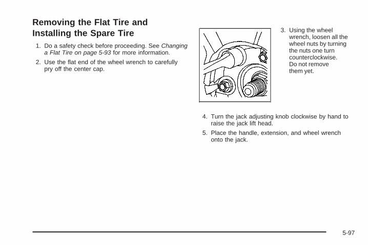
Removing the Flat Tire andInstalling the Spare Tire1. Do a safety check before proceeding. See Changing
a Flat Tire on page 5-93 for more information.
2. Use the flat end of the wheel wrench to carefullypry off the center cap.
3. Using the wheelwrench, loosen all thewheel nuts by turningthe nuts one turncounterclockwise.Do not removethem yet.
4. Turn the jack adjusting knob clockwise by hand toraise the jack lift head.
5. Place the handle, extension, and wheel wrenchonto the jack.
5-97

A. Front Frame/Rear Axle
B. Jack
C. HandleD. Extension(s)E. Wheel Wrench
6. Place the jack in the appropriate position nearestthe flat tire.
{CAUTION:
Getting under a vehicle when it is jacked up isdangerous. If the vehicle slips off the jack, youcould be badly injured or killed. Never get under avehicle when it is supported only by a jack.
{CAUTION:
Raising your vehicle with the jack improperlypositioned can damage the vehicle and even makethe vehicle fall. To help avoid personal injury andvehicle damage, be sure to fit the jack lift head intothe proper location before raising the vehicle.
Front Position Rear Position
5-98

7. Raise the vehicle by turning the jack handleclockwise. Raise the vehicle far enough off theground so there is enough room for the sparetire to fit.
8. Remove all the wheelnuts and the flat tire.
5-99

{CAUTION:
Rust or dirt on a wheel, or on the parts to which itis fastened, can make wheel nuts become looseafter time. The wheel could come off and cause anaccident. When changing a wheel, remove any rustor dirt from places where the wheel attaches to thevehicle. In an emergency, use a cloth or a papertowel to do this; but be sure to use a scraper or wirebrush later, if needed, to get all the rust or dirt off.See Changing a Flat Tire on page 5-93.
9. Remove any rust or dirtfrom the wheel bolts,mounting surfacesand spare wheel.
10. Place the spare tire on the wheel-mounting surface.
5-100

{CAUTION:
Never use oil or grease on bolts or nuts becausethe nuts might come loose. The vehicle’s wheelcould fall off, causing a crash.
11. Put the nuts on by hand. Make sure the coneshaped end is toward the wheel.
12. Tighten each nut by hand until the wheel is heldagainst the hub. If a nut cannot be turned byhand, use the wheel wrench and see yourdealer as soon as possible.
13. Lower the vehicle by turning the jack handlecounterclockwise. Lower the jack completely.
5-101
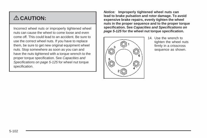
{CAUTION:
Incorrect wheel nuts or improperly tightened wheelnuts can cause the wheel to come loose and evencome off. This could lead to an accident. Be sure touse the correct wheel nuts. If you have to replacethem, be sure to get new original equipment wheelnuts. Stop somewhere as soon as you can andhave the nuts tightened with a torque wrench to theproper torque specification. See Capacities andSpecifications on page 5-125 for wheel nut torquespecification.
Notice: Improperly tightened wheel nuts canlead to brake pulsation and rotor damage. To avoidexpensive brake repairs, evenly tighten the wheelnuts in the proper sequence and to the proper torquespecification. See Capacities and Specifications onpage 5-125 for the wheel nut torque specification.
14. Use the wrench totighten the wheel nutsfirmly in a crisscrosssequence as shown.
5-102

Secondary Latch SystemThis vehicle may have an underbody-mounted tirehoist assembly equipped with a secondary latch system.It is designed to stop the spare tire, if the vehicle has one,from suddenly falling off the vehicle if the cable holdingthe spare tire is damaged. For the secondary latch towork, the tire must be stored with the valve stem pointingup. See Storing a Flat or Spare Tire and Tools onpage 5-106 for instructions on storing the spare or flattire correctly.
{CAUTION:
Before beginning this procedure read all theinstructions. Failure to read and follow theinstructions could damage the hoist assemblyand you and others could get hurt. Read andfollow the instructions listed next.
{CAUTION:
Someone standing too close during the procedurecould be injured by the jack. If the spare tire doesnot slide off the jack completely, make sure noone is behind you or on either side of you as youpull the jack out from the under spare.
To release the spare tire from the secondary latch:
1. Check under thevehicle to see if thecable is visible. If it isnot visible, proceedto Step 6.
5-103

2. If visible, first try to tighten the cable by turning thewheel wrench clockwise until you hear two clicks orfeel it skip twice. You cannot overtighten the cable.
3. Loosen the cable by turning the wheel wrenchcounterclockwise three or four turns.
4. Repeat this procedure at least two times.If the spare tire lowers to the ground, continue withStep 2 of Removing the Spare Tire and Tools onpage 5-94.
5. Turn the wrench counterclockwise untilapproximately 6 inches (15 cm) of cable is exposed.
6. Attach the jack handle, extension(s) and the wheelwrench to the jack and place it under the vehicletowards the front of the rear bumper. Positionthe center lift point of the jack under the centerof the spare tire.
7. Turn the wrench clockwise to raise the jack until itlifts the end fitting.
8. Continue raising the jack until the spare tirestops moving upward and is held firmly in place.The secondary latch has released and the sparetire is balancing on the jack.
5-104
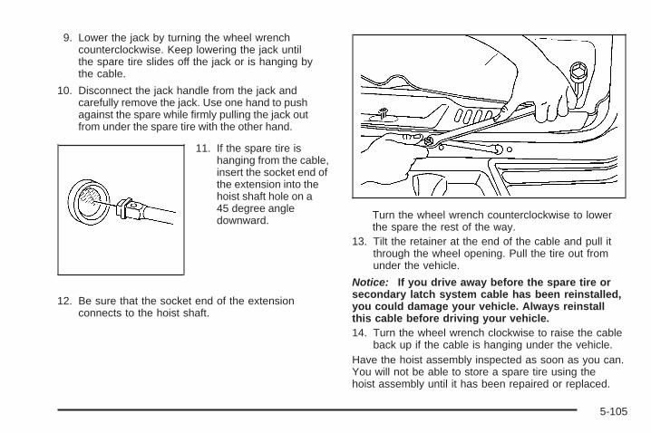
9. Lower the jack by turning the wheel wrenchcounterclockwise. Keep lowering the jack untilthe spare tire slides off the jack or is hanging bythe cable.
10. Disconnect the jack handle from the jack andcarefully remove the jack. Use one hand to pushagainst the spare while firmly pulling the jack outfrom under the spare tire with the other hand.
11. If the spare tire ishanging from the cable,insert the socket end ofthe extension into thehoist shaft hole on a45 degree angledownward.
12. Be sure that the socket end of the extensionconnects to the hoist shaft.
Turn the wheel wrench counterclockwise to lowerthe spare the rest of the way.
13. Tilt the retainer at the end of the cable and pull itthrough the wheel opening. Pull the tire out fromunder the vehicle.
Notice: If you drive away before the spare tire orsecondary latch system cable has been reinstalled,you could damage your vehicle. Always reinstallthis cable before driving your vehicle.14. Turn the wheel wrench clockwise to raise the cable
back up if the cable is hanging under the vehicle.Have the hoist assembly inspected as soon as you can.You will not be able to store a spare tire using thehoist assembly until it has been repaired or replaced.
5-105

Storing a Flat or Spare Tire andTools
{CAUTION:
Storing a jack, a tire, or other equipment in thepassenger compartment of the vehicle couldcause injury. In a sudden stop or collision, looseequipment could strike someone. Store all these inthe proper place.
{CAUTION:
The underbody-mounted spare tire needs to bestored with the valve stem pointing up. If thespare tire is stored with the valve stem pointingdownward, its secondary latch will not workproperly and the spare tire could loosen andsuddenly fall from your vehicle. If this happenedwhen your vehicle was being driven, the tire mightcontact a person or another vehicle, causing injuryand, of course, damage to itself as well. Be surethe underbody-mounted spare tire is stored with itsvalve stem pointing up.
Notice: An aluminum wheel with a flat tire shouldalways be stored under the vehicle with the hoist.However, storing it that way for an extended periodcould damage the wheel. To avoid this, always stowthe wheel properly with the valve stem pointing upand have the wheel repaired as soon as possible.
5-106
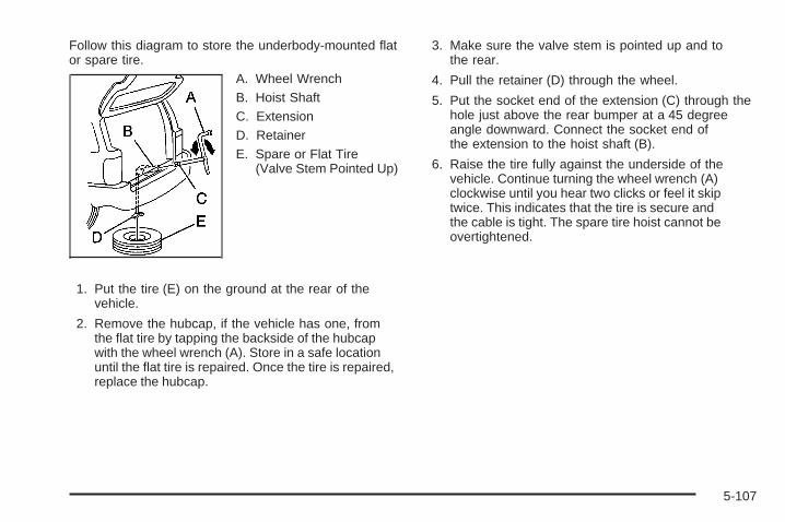
Follow this diagram to store the underbody-mounted flator spare tire.
A. Wheel WrenchB. Hoist ShaftC. ExtensionD. RetainerE. Spare or Flat Tire
(Valve Stem Pointed Up)
1. Put the tire (E) on the ground at the rear of thevehicle.
2. Remove the hubcap, if the vehicle has one, fromthe flat tire by tapping the backside of the hubcapwith the wheel wrench (A). Store in a safe locationuntil the flat tire is repaired. Once the tire is repaired,replace the hubcap.
3. Make sure the valve stem is pointed up and tothe rear.
4. Pull the retainer (D) through the wheel.
5. Put the socket end of the extension (C) through thehole just above the rear bumper at a 45 degreeangle downward. Connect the socket end ofthe extension to the hoist shaft (B).
6. Raise the tire fully against the underside of thevehicle. Continue turning the wheel wrench (A)clockwise until you hear two clicks or feel it skiptwice. This indicates that the tire is secure andthe cable is tight. The spare tire hoist cannot beovertightened.
5-107
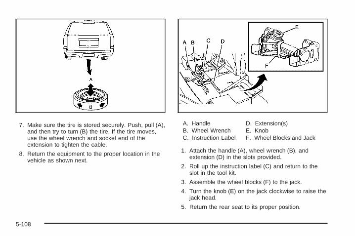
7. Make sure the tire is stored securely. Push, pull (A),and then try to turn (B) the tire. If the tire moves,use the wheel wrench and socket end of theextension to tighten the cable.
8. Return the equipment to the proper location in thevehicle as shown next.
A. HandleB. Wheel WrenchC. Instruction Label
D. Extension(s)E. KnobF. Wheel Blocks and Jack
1. Attach the handle (A), wheel wrench (B), andextension (D) in the slots provided.
2. Roll up the instruction label (C) and return to theslot in the tool kit.
3. Assemble the wheel blocks (F) to the jack.
4. Turn the knob (E) on the jack clockwise to raise thejack head.
5. Return the rear seat to its proper position.
5-108

Spare TireThis vehicle may have a spare tire. Although thespare tire was fully inflated when the vehicle was new,it can lose air after a time. Check the inflation pressureregularly. See Inflation - Tire Pressure on page 5-65and Loading the Vehicle on page 4-33 for informationregarding proper tire inflation and loading your vehicle.For instruction on how to remove, install or store a sparetire, see Removing the Flat Tire and Installing the SpareTire on page 5-97 and Storing a Flat or Spare Tire andTools on page 5-106.
After installing the spare tire on your vehicle, you shouldstop as soon as possible and make sure the spare iscorrectly inflated. The spare tire is made to perform wellat speeds up to 70 mph (112 km/h) at the recommendedinflation pressure, so you can finish your trip.
Have the damaged or flat road tire repaired or replacedas soon as you can and installed back onto your vehicle.This way, a spare tire will be available in case you need itagain. Do not mix tires and wheels of different sizes,because they will not fit. Keep your spare tire and itswheel together.
Appearance Care
Interior CleaningThe vehicle’s interior will continue to look its best if it iscleaned often. Although not always visible, dust anddirt can accumulate on the upholstery. Dirt can damagecarpet, fabric, leather, and plastic surfaces. Regularvacuuming is recommended to remove particles from theupholstery. It is important to keep the upholstery frombecoming and remaining heavily soiled. Soils should beremoved as quickly as possible. The vehicle’s interiormay experience extremes of heat that could causestains to set rapidly.
Lighter colored interiors may require more frequentcleaning. Use care because newspapers and garmentsthat transfer color to home furnishings may alsotransfer color to the vehicle’s interior.
5-109

When cleaning the vehicle’s interior, only use cleanersspecifically designed for the surfaces being cleaned.Permanent damage may result from using cleaners onsurfaces for which they were not intended. Use glasscleaner only on glass. Remove any accidental over-sprayfrom other surfaces immediately. To prevent over-spray,apply cleaner directly to the cleaning cloth.
Notice: Using abrasive cleaners when cleaningglass surfaces on the vehicle, could scratchthe glass and/or cause damage to the rear windowdefogger. When cleaning the glass on the vehicle,use only a soft cloth and glass cleaner.
Many cleaners contain solvents that may becomeconcentrated in the vehicle’s breathing space. Beforeusing cleaners, read and adhere to all safety instructionson the label. While cleaning the vehicle’s interior,maintain adequate ventilation by opening the vehicle’sdoors and windows.
Dust may be removed from small buttons and knobsusing a small brush with soft bristles.
Products that remove odors from the vehicle’supholstery and clean the vehicle’s glass can beobtained from your dealer/retailer.
Do not clean the vehicle using:
• A knife or any other sharp object to remove a soilfrom any interior surface.
• A stiff brush. It can cause damage to the vehicle’sinterior surfaces.
• Heavy pressure or aggressive rubbing with acleaning cloth. Use of heavy pressure can damagethe interior and does not improve the effectivenessof soil removal.
• Laundry detergents or dishwashing soaps withdegreasers can leave residue that streaks andattracts dirt. For liquid cleaners, about 20 dropsper gallon (3.78 L) of water is a good guide.Use only mild, neutral-pH soaps.
• Too much cleaner that saturates the upholstery.
• Organic solvents such as naptha, alcohol, etc. thatcan damage the vehicle’s interior.
5-110

Fabric/CarpetUse a vacuum cleaner with a soft brush attachmentfrequently to remove dust and loose dirt. A canistervacuum with a beater bar in the nozzle may only be usedon floor carpet and carpeted floor mats. For any soil,always try to remove it first with plain water or club soda.Before cleaning, gently remove as much of the soil aspossible using one of the following techniques:
• For liquids: gently blot the remaining soil with a papertowel. Allow the soil to absorb into the paper toweluntil no more can be removed.
• For solid dry soils: remove as much as possible andthen vacuum.
To clean:
1. Saturate a lint-free, clean white cloth with water orclub soda.
2. Wring the cloth to remove excess moisture.
3. Start on the outside edge of the soil and gently rubtoward the center. Continue cleaning, using a cleanarea of the cloth each time it becomes soiled.
4. Continue to gently rub the soiled area until thecleaning cloth remains clean.
5. If the soil is not completely removed, use a mildsoap solution and repeat the cleaning processthat was used with plain water.
If any of the soil remains, a commercial fabric cleaneror spot lifter may be necessary. When a commercialupholstery cleaner or spot lifter is to be used, test a smallhidden area for colorfastness first. If the locally cleanedarea gives any impression that a ring formation mayresult, clean the entire surface.
After the cleaning process has been completed, a papertowel can be used to blot excess moisture from thefabric or carpet.
LeatherA soft cloth dampened with water can be used toremove dust. If a more thorough cleaning is necessary,a soft cloth dampened with a mild soap solution can beused. Allow the leather to dry naturally. Do not use heatto dry. Never use steam to clean leather. Never use spotlifters or spot removers on leather. Many commercialleather cleaners and coatings that are sold to preserveand protect leather may permanently change theappearance and feel of the leather and are notrecommended. Do not use silicone or wax-basedproducts, or those containing organic solvents toclean the vehicle’s interior because they can alter theappearance by increasing the gloss in a non-uniformmanner. Never use shoe polish on leather.
5-111

Instrument Panel, Vinyl, and OtherPlastic SurfacesA soft cloth dampened with water may be used toremove dust. If a more thorough cleaning is necessary,a clean soft cloth dampened with a mild soap solution canbe used to gently remove dust and dirt. Never use spotlifters or removers on plastic surfaces. Many commercialcleaners and coatings that are sold to preserve andprotect soft plastic surfaces may permanently changethe appearance and feel of the interior and are notrecommended. Do not use silicone or wax-basedproducts, or those containing organic solvents toclean the vehicle’s interior because they can alter theappearance by increasing the gloss in a non-uniformmanner.
Some commercial products may increase gloss on theinstrument panel. The increase in gloss may causeannoying reflections in the windshield and even makeit difficult to see through the windshield under certainconditions.
Care of Safety BeltsKeep belts clean and dry.
{CAUTION:
Do not bleach or dye safety belts. It may severelyweaken them. In a crash, they might not be ableto provide adequate protection. Clean safety beltsonly with mild soap and lukewarm water.
WeatherstripsSilicone grease on weatherstrips will make them lastlonger, seal better, and not stick or squeak. Applysilicone grease with a clean cloth. During very cold,damp weather frequent application may be required.See Recommended Fluids and Lubricants on page 6-12.
5-112
Washing Your VehicleThe best way to preserve the vehicle’s finish is to keepit clean by washing it often.
Notice: Certain cleaners contain chemicals that candamage the emblems or nameplates on the vehicle.Check the cleaning product label. If it states thatit should not be used on plastic parts, do not use iton the vehicle or damage may occur and it wouldnot be covered by the warranty.
Do not wash the vehicle in direct sunlight. Use a carwashing soap. Do not use cleaning agents that arepetroleum based or that contain acid or abrasives, asthey can damage the paint, metal or plastic on thevehicle. Approved cleaning products can be obtainedfrom your dealer/retailer. Follow all manufacturers’directions regarding correct product usage, necessarysafety precautions and appropriate disposal of anyvehicle care product.
Rinse the vehicle well, before washing and after toremove all cleaning agents completely. If they areallowed to dry on the surface, they could stain.
Dry the finish with a soft, clean chamois or an all-cottontowel to avoid surface scratches and water spotting.
High pressure car washes may cause water to enterthe vehicle. Avoid using high pressure washes closerthan 12 inches (30 cm) to the surface of the vehicle.Use of power washers exceeding 1,200 psi (8 274 kPa)can result in damage or removal of paint and decals.
Cleaning Exterior Lamps/LensesUse only lukewarm or cold water, a soft cloth and acar washing soap to clean exterior lamps and lenses.Follow instructions under Washing Your Vehicle onpage 5-113.
5-113
Finish CareOccasional waxing or mild polishing of the vehicleby hand may be necessary to remove residue fromthe paint finish. Approved cleaning products canbe obtained from your dealer/retailer.
If the vehicle has a basecoat/clearcoat paint finish, theclearcoat gives more depth and gloss to the coloredbasecoat. Always use waxes and polishes that arenon-abrasive and made for a basecoat/clearcoatpaint finish.
Notice: Machine compounding or aggressivepolishing on a basecoat/clearcoat paint finishmay damage it. Use only non-abrasive waxes andpolishes that are made for a basecoat/clearcoatpaint finish on the vehicle.
Foreign materials such as calcium chloride and othersalts, ice melting agents, road oil and tar, tree sap, birddroppings, chemicals from industrial chimneys, etc., candamage the vehicle’s finish if they remain on paintedsurfaces. Wash the vehicle as soon as possible. Ifnecessary, use non-abrasive cleaners that are markedsafe for painted surfaces to remove foreign matter.
Exterior painted surfaces are subject to aging, weatherand chemical fallout that can take their toll over aperiod of years. To help keep the paint finish lookingnew, keep the vehicle garaged or covered wheneverpossible.
Protecting Exterior Bright Metal PartsBright metal parts should be cleaned regularly to keeptheir luster. Washing with water is all that is usuallyneeded. However, chrome polish may be used onchrome or stainless steel trim, if necessary.Use special care with aluminum trim. To avoiddamaging protective trim, never use auto or chromepolish, steam or caustic soap to clean aluminum.A coating of wax, rubbed to high polish, is recommendedfor all bright metal parts.
Windshield, Backglass, andWiper BladesClean the outside of the windshield and backglass withglass cleaner.Clean the rubber blades using a lint free cloth or papertowel soaked with windshield washer fluid or a milddetergent. Wash the windshield thoroughly when youclean the blades. Bugs, road grime, sap and a buildup ofvehicle wash/wax treatments may cause wiper streaking.Replace the wiper blades if they are worn or damaged.Wipers can be damaged by:• Extreme dusty conditions• Sand and salt• Heat and sun• Snow and ice, without proper removal
5-114
Aluminum WheelsNotice: Using strong soaps, chemicals, abrasivepolishes, cleaners, brushes, or cleaners that containacid on aluminum or chrome-plated wheels, coulddamage the surface of the wheel(s). The repairswould not be covered by the warranty. Use onlyapproved cleaners on aluminum or chrome-platedwheels.
Keep the wheels clean using a soft clean cloth with mildsoap and water. Rinse with clean water. After rinsingthoroughly, dry with a soft clean towel. A wax may thenbe applied.
Notice: Using chrome polish on aluminum wheelscould damage the wheels. The repairs would notbe covered by the warranty. Use chrome polish onchrome wheels only.
The surface of these wheels is similar to the paintedsurface of the vehicle. Do not use strong soaps,chemicals, abrasive polishes, abrasive cleaners,
cleaners with acid, or abrasive cleaning brusheson them because the surface could be damaged.Do not use chrome polish on aluminum wheels.
Notice: Driving the vehicle through an automaticcar wash that has silicone carbide tire cleaningbrushes, could damage the aluminum orchrome-plated wheels. The repairs would not becovered by the warranty. Never drive a vehicleequipped with aluminum or chrome-plated wheelsthrough an automatic car wash that uses siliconecarbide tire cleaning brushes.
TiresTo clean the tires, use a stiff brush with tire cleaner.
Notice: Using petroleum-based tire dressingproducts on the vehicle may damage the paint finishand/or tires. When applying a tire dressing, alwayswipe off any overspray from all painted surfaceson the vehicle.
5-115

Sheet Metal DamageIf the vehicle is damaged and requires sheet metalrepair or replacement, make sure the body repairshop applies anti-corrosion material to parts repairedor replaced to restore corrosion protection.
Original manufacturer replacement parts will providethe corrosion protection while maintaining the vehiclewarranty.
Finish DamageAny stone chips, fractures or deep scratches in thefinish should be repaired right away. Bare metalwill corrode quickly and may develop into majorrepair expense.
Minor chips and scratches can be repaired withtouch-up materials available from your dealer/retailer.Larger areas of finish damage can be corrected inyour dealer’s/retailer’s body and paint shop.
Underbody MaintenanceChemicals used for ice and snow removal and dustcontrol can collect on the underbody. If these are notremoved, corrosion and rust can develop on theunderbody parts such as fuel lines, frame, floor pan,and exhaust system even though they have corrosionprotection.
At least every spring, flush these materials from theunderbody with plain water. Clean any areas where mudand debris can collect. Dirt packed in close areas ofthe frame should be loosened before being flushed.Your dealer/retailer or an underbody car washingsystem can do this.
Chemical Paint SpottingSome weather and atmospheric conditions can create achemical fallout. Airborne pollutants can fall upon andattack painted surfaces on the vehicle. This damage cantake two forms: blotchy, ring-shaped discolorations, andsmall, irregular dark spots etched into the paint surface.
Although no defect in the paint job causes this, we willrepair, at no charge to the owner, the surfaces ofnew vehicles damaged by this fallout condition within12 months or 12,000 miles (20 000 km) of purchase,whichever occurs first.
5-116

Vehicle Identification
Vehicle Identification Number (VIN)
This is the legal identifier for your vehicle. It appears ona plate in the front corner of the instrument panel, onthe driver side. It can be seen through the windshieldfrom outside the vehicle. The VIN also appears onthe Certification/Tire and Service Parts labels and thecertificates of title and registration.
Engine IdentificationThe eighth character in the VIN is the engine code. Thiscode helps identify the vehicle’s engine, specifications,and replacement parts. See “Engine Specifications”under Capacities and Specifications on page 5-125 foryour vehicle’s engine code.
Service Parts Identification LabelThis label is on the inside of the glove box.It is very helpful if you ever need to order parts.The label has the following information:
• Vehicle Identification Number (VIN)
• Model designation
• Paint information
• Production options and special equipment
Do not remove this label from the vehicle.
5-117
Electrical System
Add-On Electrical EquipmentNotice: Do not add anything electrical to thevehicle unless you check with your dealer/retailerfirst. Some electrical equipment can damagethe vehicle and the damage would not be coveredby the vehicle’s warranty. Some add-on electricalequipment can keep other components fromworking as they should.
Add-on equipment can drain the vehicle battery, even ifthe vehicle is not operating.
The vehicle has an airbag system. Before attempting toadd anything electrical to the vehicle, see ServicingYour Airbag-Equipped Vehicle on page 1-68.
HeadlampsThe headlamp wiring is protected by four fuses.An electrical overload will cause a lamp to go on andoff. If this happens, have the headlamp wiring checkedright away.
Windshield Wiper FusesThe windshield wiper motor is protected by a circuitbreaker and a fuse. If the motor overheats due to heavysnow, etc., the wiper will stop until the motor cools.If the overload is caused by some electrical problem,have it fixed.
Power Windows and Other PowerOptionsCircuit breakers in the fuse block protect the powerwindows and other power accessories. When the currentload is too heavy, the circuit breaker opens and closes,protecting the circuit until the problem is fixed orgoes away.
5-118
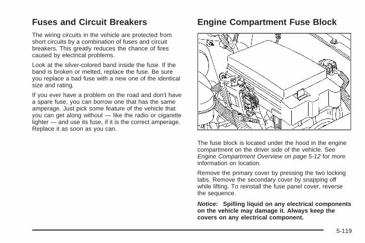
Fuses and Circuit BreakersThe wiring circuits in the vehicle are protected fromshort circuits by a combination of fuses and circuitbreakers. This greatly reduces the chance of firescaused by electrical problems.
Look at the silver-colored band inside the fuse. If theband is broken or melted, replace the fuse. Be sureyou replace a bad fuse with a new one of the identicalsize and rating.
If you ever have a problem on the road and don’t havea spare fuse, you can borrow one that has the sameamperage. Just pick some feature of the vehicle thatyou can get along without — like the radio or cigarettelighter — and use its fuse, if it is the correct amperage.Replace it as soon as you can.
Engine Compartment Fuse Block
The fuse block is located under the hood in the enginecompartment on the driver side of the vehicle. SeeEngine Compartment Overview on page 5-12 for moreinformation on location.
Remove the primary cover by pressing the two lockingtabs. Remove the secondary cover by snapping offwhile lifting. To reinstall the fuse panel cover, reversethe sequence.
Notice: Spilling liquid on any electrical componentson the vehicle may damage it. Always keep thecovers on any electrical component.
5-119
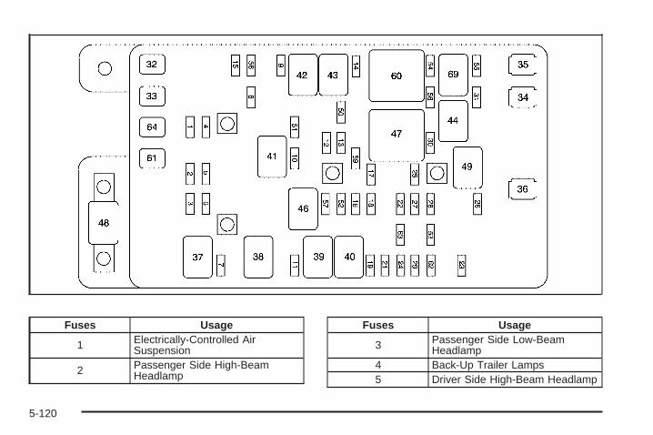
Fuses Usage
1 Electrically-Controlled AirSuspension
2 Passenger Side High-BeamHeadlamp
Fuses Usage
3 Passenger Side Low-BeamHeadlamp
4 Back-Up Trailer Lamps5 Driver Side High-Beam Headlamp
5-120
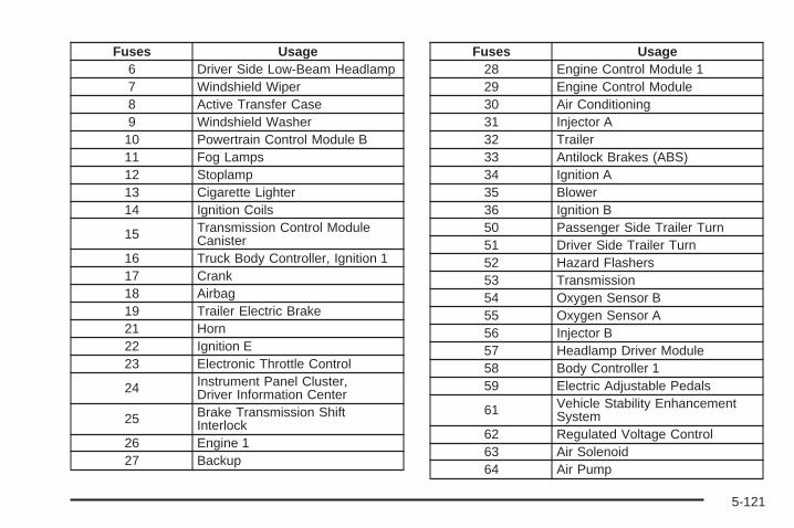
Fuses Usage6 Driver Side Low-Beam Headlamp7 Windshield Wiper8 Active Transfer Case9 Windshield Washer
10 Powertrain Control Module B11 Fog Lamps12 Stoplamp13 Cigarette Lighter14 Ignition Coils
15 Transmission Control ModuleCanister
16 Truck Body Controller, Ignition 117 Crank18 Airbag19 Trailer Electric Brake21 Horn22 Ignition E23 Electronic Throttle Control
24 Instrument Panel Cluster,Driver Information Center
25 Brake Transmission ShiftInterlock
26 Engine 127 Backup
Fuses Usage28 Engine Control Module 129 Engine Control Module30 Air Conditioning31 Injector A32 Trailer33 Antilock Brakes (ABS)34 Ignition A35 Blower36 Ignition B50 Passenger Side Trailer Turn51 Driver Side Trailer Turn52 Hazard Flashers53 Transmission54 Oxygen Sensor B55 Oxygen Sensor A56 Injector B57 Headlamp Driver Module58 Body Controller 159 Electric Adjustable Pedals
61 Vehicle Stability EnhancementSystem
62 Regulated Voltage Control63 Air Solenoid64 Air Pump
5-121

Relays Usage37 Headlamp Wiper38 Rear Window Wiper/Washer39 Fog Lamps40 Horn41 Fuel Pump42 Windshield Washer43 High-Beam Headlamp44 Air Conditioning46 Headlamp Driver Module47 Starter49 Electric Adjustable Pedal60 Powertrain69 Air Solenoid
Miscellaneous Usage48 Instrument Panel Battery
Rear Underseat Fuse Block
5-122
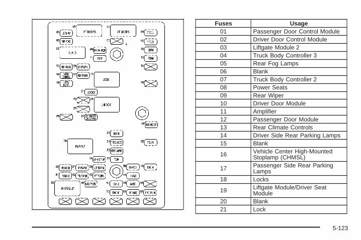
Fuses Usage01 Passenger Door Control Module02 Driver Door Control Module03 Liftgate Module 204 Truck Body Controller 305 Rear Fog Lamps06 Blank07 Truck Body Controller 208 Power Seats09 Rear Wiper10 Driver Door Module11 Amplifier12 Passenger Door Module13 Rear Climate Controls14 Driver Side Rear Parking Lamps15 Blank
16 Vehicle Center High-MountedStoplamp (CHMSL)
17 Passenger Side Rear ParkingLamps
18 Locks
19 Liftgate Module/Driver SeatModule
20 Blank21 Lock
5-123
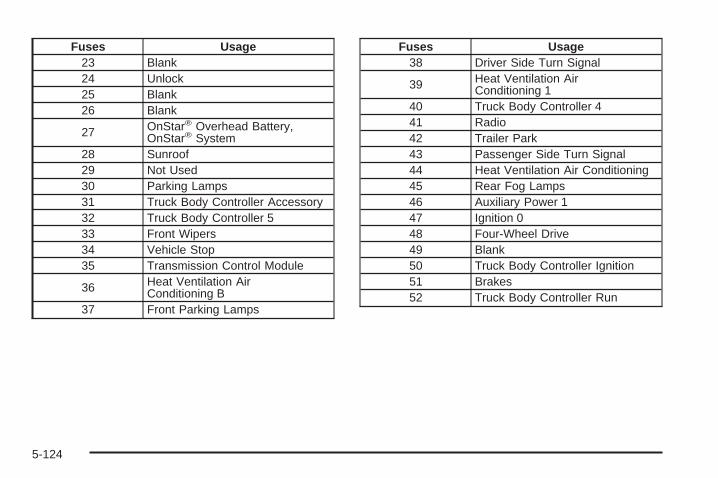
Fuses Usage23 Blank24 Unlock25 Blank26 Blank
27 OnStar® Overhead Battery,OnStar® System
28 Sunroof29 Not Used30 Parking Lamps31 Truck Body Controller Accessory32 Truck Body Controller 533 Front Wipers34 Vehicle Stop35 Transmission Control Module
36 Heat Ventilation AirConditioning B
37 Front Parking Lamps
Fuses Usage38 Driver Side Turn Signal
39 Heat Ventilation AirConditioning 1
40 Truck Body Controller 441 Radio42 Trailer Park43 Passenger Side Turn Signal44 Heat Ventilation Air Conditioning45 Rear Fog Lamps46 Auxiliary Power 147 Ignition 048 Four-Wheel Drive49 Blank50 Truck Body Controller Ignition51 Brakes52 Truck Body Controller Run
5-124

Capacities and SpecificationsThe following approximate capacities are given in English and metric conversions. See Recommended Fluids andLubricants on page 6-12 for more information.
ApplicationCapacities
English Metric
Air Conditioning Refrigerant R134a
For the air conditioning system refrigerant chargeamount, see the refrigerant caution label located
under the hood. See your dealer for moreinformation.
Cooling System
4.2L L6 9.7 qt 9.2 L
5.3L V8 11.2 qt 10.6 L
6.0L V8 11.2 qt 10.6 L
Engine Oil with Filter
4.2L L6 7.0 qt 6.6 L
5.3L V8 6.0 qt 5.7 L
6.0L V8 6.0 qt 5.7 L
5-125
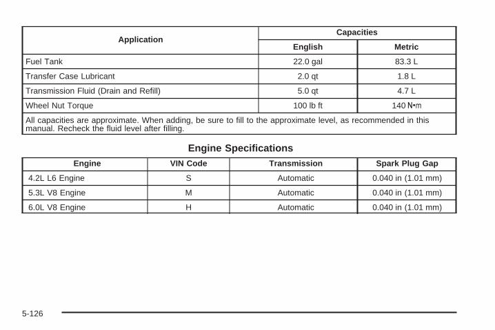
ApplicationCapacities
English Metric
Fuel Tank 22.0 gal 83.3 L
Transfer Case Lubricant 2.0 qt 1.8 L
Transmission Fluid (Drain and Refill) 5.0 qt 4.7 L
Wheel Nut Torque 100 lb ft 140 Y
All capacities are approximate. When adding, be sure to fill to the approximate level, as recommended in thismanual. Recheck the fluid level after filling.
Engine SpecificationsEngine VIN Code Transmission Spark Plug Gap
4.2L L6 Engine S Automatic 0.040 in (1.01 mm)
5.3L V8 Engine M Automatic 0.040 in (1.01 mm)
6.0L V8 Engine H Automatic 0.040 in (1.01 mm)
5-126
Maintenance Schedule ......................................6-2Introduction ...................................................6-2Maintenance Requirements ..............................6-2Your Vehicle and the Environment ....................6-2Using the Maintenance Schedule ......................6-2Scheduled Maintenance ...................................6-4Additional Required Services ............................6-6Maintenance Footnotes ...................................6-7
Owner Checks and Services ............................6-8At Each Fuel Fill ............................................6-9At Least Once a Month ...................................6-9At Least Once a Year ...................................6-10Recommended Fluids and Lubricants ...............6-12Maintenance Replacement Parts .....................6-14Engine Drive Belt Routing ..............................6-15Maintenance Record .....................................6-16
Section 6 Maintenance Schedule
6-1

Maintenance Schedule
IntroductionImportant: Keep engine oil at the proper level andchange as recommended.
Have you purchased the GM Protection Plan? The Plansupplements the vehicle warranties. See the Warrantyand Owner Assistance booklet or your dealer/retailer fordetails.
Maintenance RequirementsNotice: Maintenance intervals, checks, inspections,replacement parts, and recommended fluids andlubricants as prescribed in this manual are necessaryto keep this vehicle in good working condition.Any damage caused by failure to follow scheduledmaintenance might not be covered by the vehiclewarranty.
Your Vehicle and the EnvironmentProper vehicle maintenance not only helps to keepthe vehicle in good working condition, but also helpsthe environment. All recommended maintenance isimportant. Improper vehicle maintenance can even affectthe quality of the air we breathe. Improper fluid levels orthe wrong tire inflation can increase the level of emissionsfrom the vehicle. To help protect the environment, and tokeep the vehicle in good condition, be sure to maintainthe vehicle properly.
Using the Maintenance ScheduleWe want to help keep this vehicle in good workingcondition. But we do not know exactly how you will driveit. You might drive very short distances only a fewtimes a week. Or you might drive long distances all thetime in very hot, dusty weather. You might use thevehicle in making deliveries. Or you might driveit to work, to do errands, or in many other ways.
Because of all the different ways people use theirvehicles, maintenance needs vary. You might needmore frequent checks and replacements. So please readthe following and note how you drive. If you have anyquestions on how to keep the vehicle in good condition,see your dealer/retailer.
6-2

This schedule is for vehicles that:• carry passengers and cargo within recommended
limits on the Tire and Loading Information label.See Loading the Vehicle on page 4-33.
• are driven on reasonable road surfaces within legaldriving limits.
• are driven off-road in the recommended manner.See Off-Road Driving on page 4-14.
• use the recommended fuel. See Gasoline Octaneon page 5-6.
The services in Scheduled Maintenance on page 6-4should be performed when indicated. See AdditionalRequired Services on page 6-6 and MaintenanceFootnotes on page 6-7 for further information.
{CAUTION:
Performing maintenance work on a vehicle can bedangerous. In trying to do some jobs, you can beseriously injured. Do your own maintenance workonly if you have the required know-how and theproper tools and equipment for the job. If you haveany doubt, see your dealer/retailer to have aqualified technician do the work. See Doing YourOwn Service Work on page 5-4.
Some maintenance services can be complex.So, unless you are technically qualified and havethe necessary equipment, have your dealer/retailerdo these jobs.
When you go to your dealer/retailer for service,trained and supported service technicians willperform the work using genuine parts.
To purchase service information, see ServicePublications Ordering Information on page 7-16.
Owner Checks and Services on page 6-8 tells whatshould be checked, when to check it, and what caneasily be done to help keep the vehicle in good condition.
The proper replacement parts, fluids, and lubricants touse are listed in Recommended Fluids and Lubricantson page 6-12 and Maintenance Replacement Partson page 6-14. When the vehicle is serviced, make surethese are used. All parts should be replaced and allnecessary repairs done before you or anyone elsedrives the vehicle. We recommend the use of genuineparts from your dealer/retailer.
6-3

Scheduled MaintenanceWhen the change engine oil light or CHANGE ENGINEOIL DIC message displays, service is required for thevehicle. See Change Engine Oil Light on page 3-43 orDIC Warnings and Messages on page 3-51. Have thevehicle serviced as soon as possible within the next600 miles (1 000 km). It is possible that, if driving underthe best conditions, the engine oil life system may notindicate that vehicle service is necessary for over a year.However, the engine oil and filter must be changed atleast once a year and at this time the system must bereset. Your dealer/retailer has trained service technicianswho will perform this work using genuine parts and resetthe system.
If the engine oil life system is ever reset accidentally,service the vehicle within 3,000 miles (5 000 km) sincethe last service. Remember to reset the oil life systemwhenever the oil is changed. See Engine Oil Life Systemon page 5-22 for information on the Engine Oil LifeSystem and resetting the system.
When the change engine oil light or CHANGE ENGINEOIL DIC message appears, certain services, checks,and inspections are required. Required services aredescribed in the following for “Maintenance I” and“Maintenance II.” Generally, it is recommended that thefirst service be Maintenance I, the second service beMaintenance II, and then alternate Maintenance I andMaintenance II thereafter. However, in some cases,Maintenance II may be required more often.
Maintenance I — Use Maintenance I if the light ormessage displays within 10 months since the vehiclewas purchased or Maintenance II was performed.
Maintenance II — Use Maintenance II if the previousservice performed was Maintenance I. Always useMaintenance II whenever the light or message displays10 months or more since the last service or if thelight or message has not come on at all for one year.
6-4
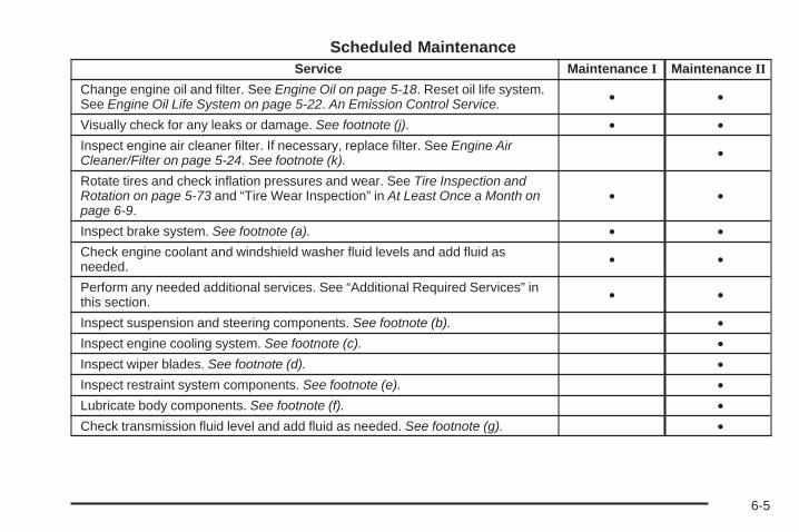
Scheduled MaintenanceService Maintenance I Maintenance II
Change engine oil and filter. See Engine Oil on page 5-18. Reset oil life system.See Engine Oil Life System on page 5-22. An Emission Control Service. • •
Visually check for any leaks or damage. See footnote (j). • •Inspect engine air cleaner filter. If necessary, replace filter. See Engine AirCleaner/Filter on page 5-24. See footnote (k). •
Rotate tires and check inflation pressures and wear. See Tire Inspection andRotation on page 5-73 and “Tire Wear Inspection” in At Least Once a Month onpage 6-9.
• •
Inspect brake system. See footnote (a). • •Check engine coolant and windshield washer fluid levels and add fluid asneeded. • •
Perform any needed additional services. See “Additional Required Services” inthis section. • •
Inspect suspension and steering components. See footnote (b). •Inspect engine cooling system. See footnote (c). •Inspect wiper blades. See footnote (d). •Inspect restraint system components. See footnote (e). •Lubricate body components. See footnote (f). •Check transmission fluid level and add fluid as needed. See footnote (g). •
6-5

Additional Required ServicesThe following services should be performed at the first maintenance service (I or II) after the indicated miles(kilometers) shown for each item.
Additional Required Services
Service and Miles (Kilometers) 25,000(40 000)
50,000(80 000)
75,000(120 000)
100,000(160 000)
125,000(200 000)
150,000(240 000)
Inspect fuel system for damage or leaks. • • • • • •Inspect exhaust system for loose ordamaged components. • • • • • •
Replace engine air cleaner filter. SeeEngine Air Cleaner/Filter on page 5-24. • • •
Change automatic transmission fluid andfilter (severe service). See footnotes (g)and (h).
• • •
Change automatic transmission fluid andfilter (normal service). See footnote (g). •
Automatic transfer case only: Changetransfer case fluid. See footnote (g). • • •
Replace spark plugs. An EmissionControl Service. •
V8 engine only: Inspect spark plug wires.An Emission Control Service. •
6-6

Additional Required Services (cont’d)
Service and Miles (Kilometers) 25,000(40 000)
50,000(80 000)
75,000(120 000)
100,000(160 000)
125,000(200 000)
150,000(240 000)
Engine cooling system service (orevery five years, whichever occurs first).An Emission Control Service.See footnote (i).
•
Inspect engine accessory drive belt.An Emission Control Service.See footnote (l).
•
Maintenance Footnotes(a) Visually inspect brake lines and hoses for properhook-up, binding, leaks, cracks, chafing, etc. Inspect discbrake pads for wear and rotors for surface condition.Inspect other brake parts, including calipers, parkingbrake, etc.
(b) Visually inspect front and rear suspension andsteering system for damaged, loose, or missing parts orsigns of wear. Inspect power steering lines and hosesfor proper hook-up, binding, leaks, cracks, chafing, etc.
(c) Visually inspect hoses and have them replaced if theyare cracked, swollen, or deteriorated. Inspect all pipes,fittings and clamps; replace with genuine parts asneeded. To help ensure proper operation, a pressure testof the cooling system and pressure cap and cleaning theoutside of the radiator and air conditioning condenser isrecommended at least once a year.
(d) Inspect wiper blades for wear, cracking, orcontamination. Clean the windshield and wiper blades, ifcontaminated. Replace wiper blades that are worn ordamaged. See Windshield Wiper Blade Replacement onpage 5-55 and Windshield, Backglass, and Wiper Bladeson page 5-114 for more information.
6-7

(e) Make sure the safety belt reminder light and safetybelt assemblies are working properly. Look for any otherloose or damaged safety belt system parts. If you seeanything that might keep a safety belt system from doingits job, have it repaired. Have any torn or frayed safetybelts replaced. Also see Checking the Restraint Systemson page 1-70.(f) Lubricate all key lock cylinders, hood latch assembly,secondary latch, pivots, spring anchor, release pawl,rear compartment hinges, outer liftgate handle pivotpoints, rear door detent link, roller mechanism, liftgatehandle pivot points, latch bolt, fuel door hinge, cargo doorhinge, locks, and folding seat hardware. More frequentlubrication may be required when exposed to a corrosiveenvironment. Applying silicone grease on weatherstripswith a clean cloth will make them last longer, seal better,and not stick or squeak.(g) Inspect hoses for cracks, chafing, leaks, kinks, andproper installation.(h) Change automatic transmission fluid and filter if thevehicle is mainly driven under one or more of theseconditions:
− In heavy city traffic where the outside temperatureregularly reaches 90°F (32°C) or higher.
− In hilly or mountainous terrain.− When doing frequent trailer towing.− Uses such as found in taxi, police, or delivery
service.
(i) Drain, flush, and refill cooling system. This service canbe complex; you should have your dealer/retailer performthis service. See Engine Coolant on page 5-29 for what touse. Inspect hoses. Clean radiator, condenser, pressurecap, and filler neck. Pressure test the cooling system andpressure cap.
(j) A fluid loss in any vehicle system could indicate aproblem. Have the system inspected and repaired andthe fluid level checked. Add fluid if needed.
(k) If driving regularly under dusty conditions, inspectthe filter at each engine oil change.
(l) Visually inspect belt for fraying, excessive cracks, orobvious damage. Replace belt if necessary.
Owner Checks and ServicesThese owner checks and services should be performedat the intervals specified to help ensure vehicle safety,dependability, and emission control performance. Yourdealer/retailer can assist with these checks and services.
Be sure any necessary repairs are completed at once.Whenever any fluids or lubricants are added to thevehicle, make sure they are the proper ones, as shownin Recommended Fluids and Lubricants on page 6-12.
6-8
At Each Fuel FillIt is important to perform these underhood checks ateach fuel fill.
Engine Oil Level Check
Notice: It is important to check the engine oilregularly and keep it at the proper level. Failure tokeep the engine oil at the proper level can causedamage to the engine not covered by the vehiclewarranty.
Check the engine oil level and add the proper oil ifnecessary. See Engine Oil on page 5-18.
Engine Coolant Level CheckCheck the engine coolant level and add DEX-COOL®
coolant mixture if necessary. See Engine Coolanton page 5-29.
Windshield Washer Fluid Level CheckCheck the windshield washer fluid level in the windshieldwasher fluid reservoir and add the proper fluid ifnecessary.
At Least Once a Month
Tire Inflation CheckInspect the vehicle’s tires and make sure they are inflatedto the correct pressures. Do not forget to check the sparetire, if the vehicle has one. See Inflation - Tire Pressureon page 5-65. If the vehicle has a spare tire, check tomake sure it is stored securely. See Changing a Flat Tireon page 5-93.
Tire Wear InspectionTire rotation may be required for high mileage highwaydrivers prior to the Engine Oil Life System servicenotification. Check the tires for wear and, if necessary,rotate the tires. See Tire Inspection and Rotation onpage 5-73.
6-9
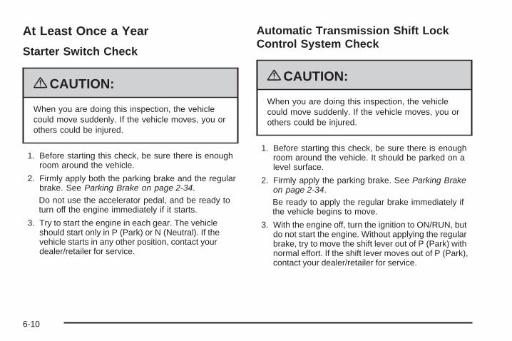
At Least Once a Year
Starter Switch Check
{CAUTION:
When you are doing this inspection, the vehiclecould move suddenly. If the vehicle moves, you orothers could be injured.
1. Before starting this check, be sure there is enoughroom around the vehicle.
2. Firmly apply both the parking brake and the regularbrake. See Parking Brake on page 2-34.Do not use the accelerator pedal, and be ready toturn off the engine immediately if it starts.
3. Try to start the engine in each gear. The vehicleshould start only in P (Park) or N (Neutral). If thevehicle starts in any other position, contact yourdealer/retailer for service.
Automatic Transmission Shift LockControl System Check
{CAUTION:
When you are doing this inspection, the vehiclecould move suddenly. If the vehicle moves, you orothers could be injured.
1. Before starting this check, be sure there is enoughroom around the vehicle. It should be parked on alevel surface.
2. Firmly apply the parking brake. See Parking Brakeon page 2-34.Be ready to apply the regular brake immediately ifthe vehicle begins to move.
3. With the engine off, turn the ignition to ON/RUN, butdo not start the engine. Without applying the regularbrake, try to move the shift lever out of P (Park) withnormal effort. If the shift lever moves out of P (Park),contact your dealer/retailer for service.
6-10
Ignition Transmission Lock CheckWhile parked, and with the parking brake set, try to turnthe ignition to LOCK/OFF in each shift lever position.
• The ignition should turn to LOCK/OFF onlywhen the shift lever is in P (Park).
• The ignition key should come out only inLOCK/OFF.
Contact your dealer/retailer if service is required.
Parking Brake and AutomaticTransmission P (Park) MechanismCheck
{CAUTION:
When you are doing this check, the vehicle couldbegin to move. You or others could be injured andproperty could be damaged. Make sure there isroom in front of the vehicle in case it begins to roll.Be ready to apply the regular brake at once shouldthe vehicle begin to move.
Park on a fairly steep hill, with the vehicle facing downhill.Keeping your foot on the regular brake, set the parkingbrake.
• To check the parking brake’s holding ability: With theengine running and the transmission in N (Neutral),slowly remove foot pressure from the regular brakepedal. Do this until the vehicle is held by the parkingbrake only.
• To check the P (Park) mechanism’s holding ability:With the engine running, shift to P (Park). Thenrelease the parking brake followed by the regularbrake.
Contact your dealer/retailer if service is required.
Underbody Flushing ServiceAt least every spring, use plain water to flush anycorrosive materials from the underbody. Take careto clean thoroughly any areas where mud and otherdebris can collect.
Tire Sealant and Compressor KitIf the vehicle has a Tire Sealant and CompressorKit, check the sealant expiration date printed onthe instruction label of the kit at least once a year.See your dealer/retailer for a replacement canister.
6-11
Recommended Fluids andLubricantsFluids and lubricants identified below by name, partnumber, or specification can be obtained from yourdealer/retailer.
Usage Fluid/Lubricant
Engine Oil(Except
6.0L V8 Engine)
Engine oil which meets GM StandardGM6094M and displays theAmerican Petroleum InstituteCertified for Gasoline Enginesstarburst symbol. To determine theproper viscosity for your vehicle’sengine, see Engine Oil on page 5-18.
Engine Oil (6.0LV8 Engine Only)
The engine requires a special engineoil meeting GM Standard GM4718M.Oils meeting this standard can beidentified as synthetic, and shouldalso be identified with the AmericanPetroleum Institute (API) Certified forGasoline Engines starburst symbol.However, not all synthetic API oilswith the starburst symbol will meetthis GM standard. Look for and useonly an oil that meets GM StandardGM4718M. For the proper viscosity,see Engine Oil on page 5-18.
Engine Coolant50/50 mixture of clean, drinkablewater and use only DEX-COOL®
Coolant. See Engine Coolant onpage 5-29.
Usage Fluid/LubricantHydraulic Brake
SystemDelco® Supreme 11 Brake Fluid orequivalent DOT-3 brake fluid.
WindshieldWasher Optikleen® Washer Solvent.
Parking BrakeCable Guides
Chassis Lubricant(GM Part No. U.S. 12377985,in Canada 88901242) or lubricantmeeting requirements of NLGI #2,Category LB or GC-LB.
Power SteeringSystem
GM Power Steering Fluid(GM Part No. U.S. 89021184,in Canada 89021186).
AutomaticTransmission
DEXRON®-VI AutomaticTransmission Fluid.
Key LockCylinders
Multi-Purpose Lubricant, Superlube(GM Part No. U.S. 12346241,in Canada 10953474).
ChassisLubrication
Chassis Lubricant(GM Part No. U.S. 12377985,in Canada 88901242) or lubricantmeeting requirements of NLGI #2,Category LB or GC-LB.
Front Axle
SAE 75W-90Synthetic Axle Lubricant(GM Part No. U.S. 89021677,in Canada 89021678) meetingGM Specification 9986115.
6-12

Usage Fluid/Lubricant
Rear Axle(Except SS
Model)
SAE 75W-90Synthetic Axle Lubricant(GM Part No. U.S. 89021677,in Canada 89021678) meetingGM Specification 9986115.
Rear Axle(SS Model)
SAE 75W-90 SyntheticAxle Lubricant(GM Part No. U.S. 89021677, inCanada 89021678) meeting GMSpecification 9986115. With acomplete drain and refill add5.5 ounces (163 ml) of Limited-SlipAxle Lubricant Additive(GM Part No. U.S. 1052358, inCanada 992694) where required.See Rear Axle on page 5-49.
Transfer CaseAUTO-TRAK II Fluid(GM Part No. U.S. 12378508,in Canada 10953626).
Rear DrivelineCenter Splineand Universal
Joints
Chassis Lubricant(GM Part No. U.S. 12377985,in Canada 88901242) or lubricantmeeting requirements of NLGI #2,Category LB or GC-LB.
ConstantVelocity
Universal Joint
Chassis Lubricant(GM Part No. U.S. 12377985,in Canada 88901242) or lubricantmeeting requirements of NLGI #2,Category LB or GC-LB.
Usage Fluid/LubricantHood LatchAssembly,Secondary
Latch, Pivots,Spring
Anchor, andRelease Pawl
Lubriplate Lubricant Aerosol(GM Part No. U.S. 12346293,in Canada 992723) or lubricantmeeting requirements of NLGI #2,Category LB or GC-LB.
Hood and DoorHinges, BodyDoor Hinge
Pins, LiftgateHinge andLinkage,
Folding Seats,and Fuel Door
Hinge
Multi-Purpose Lubricant, Superlube(GM Part No. U.S. 12346241,in Canada 10953474).
Outer TailgateHandle PivotPoints and
Hinges
Multi-Purpose Lubricant, Superlube(GM Part No. U.S. 12346241,in Canada 10953474).
WeatherstripConditioning
Weatherstrip Lubricant(GM Part No. U.S. 3634770,in Canada 10953518) orDielectric Silicone Grease(GM Part No. U.S. 12345579,in Canada 992887).
WeatherstripSqueaks
Synthetic Greasewith Teflon, Superlube(GM Part No. U.S. 12371287,in Canada 10953437).
6-13

Maintenance Replacement PartsReplacement parts identified below by name, part number, or specification can be obtained from your dealer.
Part GM Part Number ACDelco Part Number
Automatic Transmission Filter Kit 24208576 24208576
Engine Air Cleaner/Filter 15036141 A2014C
Engine Oil Filter
4.2L L6 89017342 PF61
5.3L V8; 6.0L V8 89017524 PF48
Spark Plugs
4.2 L6 12598004 41-103
5.3L V8; 6.0L V8 12609877 41-985
Wiper Blades
Front – 22 in (56 cm) 12368668 —
Rear – 16 in (41 cm) 15232655 —
6-14

Engine Drive Belt Routing
4.2L L6 Engine
5.3L V8 and 6.0L V8 Engines
6-15
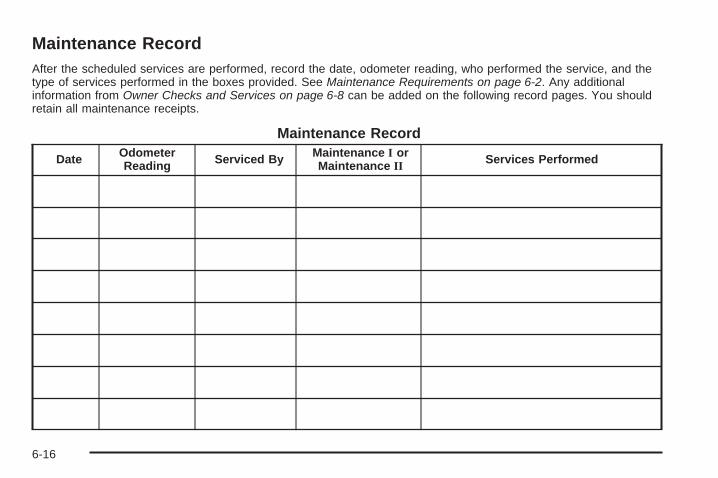
Maintenance RecordAfter the scheduled services are performed, record the date, odometer reading, who performed the service, and thetype of services performed in the boxes provided. See Maintenance Requirements on page 6-2. Any additionalinformation from Owner Checks and Services on page 6-8 can be added on the following record pages. You shouldretain all maintenance receipts.
Maintenance Record
Date OdometerReading Serviced By Maintenance I or
Maintenance II Services Performed
6-16

Maintenance Record (cont’d)
Date OdometerReading Serviced By Maintenance I or
Maintenance II Services Performed
6-17
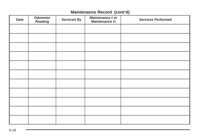
Maintenance Record (cont’d)
Date OdometerReading Serviced By Maintenance I or
Maintenance II Services Performed
6-18

Customer Assistance and Information ...............7-2Customer Satisfaction Procedure ......................7-2Online Owner Center ......................................7-5Customer Assistance for
Text Telephone (TTY) Users .........................7-6Customer Assistance Offices ............................7-6GM Mobility Reimbursement Program ................7-7Roadside Assistance Program ..........................7-7Scheduling Service Appointments ....................7-10Courtesy Transportation .................................7-11Collision Damage Repair ................................7-12
Reporting Safety Defects ................................7-15Reporting Safety Defects to the
United States Government ..........................7-15Reporting Safety Defects to the
Canadian Government ................................7-16Reporting Safety Defects to General Motors .....7-16Service Publications Ordering Information .........7-16
Vehicle Data Recording and Privacy ................7-17Event Data Recorders ...................................7-18OnStar® ......................................................7-19Navigation System ........................................7-19Radio Frequency Identification (RFID) ..............7-19
Section 7 Customer Assistance Information
7-1

Customer Assistance andInformation
Customer Satisfaction ProcedureYour satisfaction and goodwill are important to yourdealer and to Chevrolet. Normally, any concerns with thesales transaction or the operation of the vehicle will beresolved by the dealer’s sales or service departments.Sometimes, however, despite the best intentions of allconcerned, misunderstandings can occur. If your concernhas not been resolved to your satisfaction, the followingsteps should be taken:
STEP ONE: Discuss your concern with a member ofdealership management. Normally, concerns can bequickly resolved at that level. If the matter has alreadybeen reviewed with the sales, service, or parts manager,contact the owner of the dealership or the generalmanager.
STEP TWO: If after contacting a member of dealershipmanagement, it appears your concern cannot beresolved by the dealership without further help, in theU.S., call the Chevrolet Customer Assistance Centerat 1-800-222-1020. In Canada, call General Motorsof Canada Customer Communication Centre at1-800-263-3777 (English), or 1-800-263-7854 (French).
We encourage you to call the toll-free number in order togive your inquiry prompt attention. Have the followinginformation available to give the Customer AssistanceRepresentative:
• Vehicle Identification Number (VIN). This is availablefrom the vehicle registration or title, or the plate at thetop left of the instrument panel and visible throughthe windshield.
• Dealership name and location.
• Vehicle delivery date and present mileage.
When contacting Chevrolet, remember that yourconcern will likely be resolved at a dealer’s facility.That is why we suggest following Step One first.
7-2
STEP THREE — U.S. Owners: Both General Motorsand your dealer are committed to making sure you arecompletely satisfied with your new vehicle. However, ifyou continue to remain unsatisfied after following theprocedure outlined in Steps One and Two, you can filewith the Better Business Bureau (BBB) Auto LineProgram to enforce your rights.
The BBB Auto Line Program is an out of court programadministered by the Council of Better Business Bureausto settle automotive disputes regarding vehicle repairs orthe interpretation of the New Vehicle Limited Warranty.Although you may be required to resort to this informaldispute resolution program prior to filing a court action,use of the program is free of charge and your case willgenerally be heard within 40 days. If you do not agreewith the decision given in your case, you may reject it andproceed with any other venue for relief available to you.
You may contact the BBB Auto Line Program usingthe toll-free telephone number or write them at thefollowing address:
BBB Auto Line ProgramCouncil of Better Business Bureaus, Inc.4200 Wilson BoulevardSuite 800Arlington, VA 22203-1838
Telephone: 1-800-955-5100dr.bbb.org/goauto
This program is available in all 50 states and the Districtof Columbia. Eligibility is limited by vehicle age, mileage,and other factors. General Motors reserves the right tochange eligibility limitations and/or discontinue itsparticipation in this program.
7-3
STEP THREE — Canadian Owners: In the event thatyou do not feel your concerns have been addressedafter following the procedure outlined in Steps 1 and 2,General Motors of Canada Limited wants you to be awareof its participation in a no-charge Mediation/ArbitrationProgram. General Motors of Canada Limited hascommitted to binding arbitration of owner disputesinvolving factory-related vehicle service claims. Theprogram provides for the review of the facts involvedby an impartial third party arbiter, and may include aninformal hearing before the arbiter. The program isdesigned so that the entire dispute settlement process,from the time you file your complaint to the final decision,should be completed in about 70 days. We believe ourimpartial program offers advantages over courts in mostjurisdictions because it is informal, quick, and free ofcharge.
For further information concerning eligibility in theCanadian Motor Vehicle Arbitration Plan (CAMVAP),call toll-free 1-800-207-0685, or call the General MotorsCustomer Communication Centre, 1-800-263-3777(English), 1-800-263-7854 (French), or write to:
The Mediation/Arbitration Programc/o Customer Communication CentreGeneral Motors of Canada LimitedMail Code: CA1-163-0051908 Colonel Sam DriveOshawa, Ontario L1H 8P7
Your inquiry should be accompanied by the VehicleIdentification Number (VIN).
7-4
Online Owner Center
Online Owner Center (U.S.) —www.gmownercenter.com/chevroletInformation and services customized for your specificvehicle — all in one convenient place.
• Digital owner manual, warranty information,and more
• Online service and maintenance records
• Find Chevrolet dealers for service nationwide
• Exclusive privileges and offers
• Recall notices for your specific vehicle
• OnStar® and GM Cardmember Services Earningssummaries
Other Helpful Links:Chevrolet − www.chevrolet.com
Chevrolet Merchandise — www.chevymall.com
Help Center — www.chevrolet.com/helpcenter
• FAQ
• Contact Us
My GM Canada (Canada) — www.gm.caMy GM Canada is a password-protected section ofwww.gm.ca where you can save information onGM vehicles, get personalized offers, and use handytools and forms with greater ease.
Here are a few of the valuable tools and services youwill have access to:
• My Showroom: Find and save information onvehicles and current offers in your area.
• My Dealers/Retailers: Save details such as addressand phone number for each of your preferred GMdealers/retailers.
• My Driveway: Access quick links to parts andservice estimates, check trade-in values, orschedule a service appointment by adding thevehicles you own to your driveway profile.
• My Preferences: Manage your profile and use toolsand forms with greater ease.
To sign up, visit the My GM Canada section withinwww.gm.ca.
7-5
Customer Assistance for TextTelephone (TTY) UsersTo assist customers who are deaf, hard of hearing, orspeech-impaired and who use Text Telephones (TTYs),Chevrolet has TTY equipment available at its CustomerAssistance Center. Any TTY user in the U.S. cancommunicate with Chevrolet by dialing: 1-800-833-CHEV(2438). (TTY users in Canada can dial 1-800-263-3830.)
Customer Assistance OfficesChevrolet encourages customers to call the toll-freenumber for assistance. However, if a customer wishesto write or e-mail Chevrolet, the letter should beaddressed to:
United States — Customer AssistanceChevrolet Motor DivisionChevrolet Customer Assistance CenterP.O. Box 33170Detroit, MI 48232-5170
Chevrolet.com1-800-222-10201-800-833-2438 (For Text Telephone devices (TTYs))Roadside Assistance: 1-800-CHEV-USA (243-8872)
From Puerto Rico:1-800-496-9992 (English)1-800-496-9993 (Spanish)
From U.S. Virgin Islands:1-800-496-9994
Canada — Customer AssistanceGeneral Motors of Canada LimitedCustomer Communication Centre, CA1-163-0051908 Colonel Sam DriveOshawa, Ontario L1H 8P7
gmcanada.com1-800-263-3777 (English)1-800-263-7854 (French)1-800-263-3830 (For Text Telephone devices (TTYs))Roadside Assistance: 1-800-268-6800
Overseas — Customer AssistancePlease contact the local General Motors Business Unit.
7-6

Mexico, Central America and CaribbeanIslands/Countries (Except Puerto Ricoand U.S. Virgin Islands) — CustomerAssistance
General Motors de Mexico, S. de R.L. de C.V.Customer Assistance CenterPaseo de la Reforma # 2740Col. Lomas de BezaresC.P. 11910, Mexico, D.F.01-800-508-0000Long Distance: 011-52-53 29 0 800
GM Mobility ReimbursementProgram
This program, available to qualified applicants, canreimburse you up to $1,000 of the cost of eligibleaftermarket adaptive equipment required for your vehicle,such as hand controls or a wheelchair/scooter lift.
The offer is available for a very limited period of timefrom the date of vehicle purchase/lease. For moredetails, or to determine your vehicle’s eligibility, visitgmmobility.com or call the GM Mobility AssistanceCenter at 1-800-323-9935. Text telephone (TTY) users,call 1-800-833-9935.
General Motors of Canada also has a Mobility Program.Call 1-800-GM-DRIVE (463-7483) for details. TTY userscall 1-800-263-3830.
Roadside Assistance ProgramFor U.S. purchased vehicles, call 1-800-CHEV-USA(1-800-243-8872); (Text telephone (TTY):1-888-889-2438).
For Canadian purchased vehicles, call 1-800-268-6800.
Service is available 24 hours a day, 365 days a year.
7-7
Calling for AssistanceWhen calling Roadside Assistance, have the followinginformation ready:
• Your name, home address, and home telephonenumber
• Telephone number of your location
• Location of the vehicle
• Model, year, color, and license plate number of thevehicle
• Odometer reading, Vehicle IdentificationNumber (VIN), and delivery date of the vehicle
• Description of the problem
CoverageServices are provided up to 5 years/100,000 miles(160 000 km), whichever comes first.
In the U.S., anyone driving the vehicle is covered.In Canada, a person driving the vehicle withoutpermission from the owner is not covered.
Roadside Assistance is not a part of the New VehicleLimited Warranty. Chevrolet and General Motors ofCanada Limited reserve the right to make any changesor discontinue the Roadside Assistance program atany time without notification.
Chevrolet and General Motors of Canada Limitedreserve the right to limit services or payment to an owneror driver if they decide the claims are made too often,or the same type of claim is made many times.
7-8

Services Provided• Emergency Fuel Delivery: Delivery of enough fuel
for the vehicle to get to the nearest service station.
• Lock-Out Service: Service is provided to unlock thevehicle if you are locked out. A remote unlock may beavailable if you have OnStar®. For security reasons,the driver must present identification before thisservice is given.
• Emergency Tow From a Public Road or Highway:Tow to the nearest Chevrolet dealer for warrantyservice, or if the vehicle was in a crash and cannotbe driven. Assistance is also given when the vehicleis stuck in the sand, mud, or snow.
• Flat Tire Change: Service is provided to change aflat tire with the spare tire. The spare tire, if equipped,must be in good condition and properly inflated.It is the owner’s responsibility for the repair orreplacement of the tire if it is not covered by thewarranty.
• Battery Jump Start: Service is provided to jumpstart a dead battery.
• Trip Interruption Benefits and Assistance:If your trip is interrupted due to a warranty failure,incidental expenses may be reimbursed during the5 years/100,000 miles (160 000 km) Powertrainwarranty period. Items considered are hotel, meals,and rental car.
Services Not Included in RoadsideAssistance• Impound towing caused by violation of any laws.
• Legal fines.
• Mounting, dismounting or changing of snow tires,chains, or other traction devices.
• Towing or services for vehicles driven on anon-public road or highway.
7-9
Services Specific to CanadianPurchased Vehicles• Fuel delivery: Reimbursement is approximately
$5 Canadian. Diesel fuel delivery may berestricted. Propane and other fuels are not providedthrough this service.
• Lock-Out Service: Vehicle registration is required.
• Trip Routing Service: Detailed maps of NorthAmerica are provided when requested either withthe most direct route or the most scenic route. Thereis a limit of six requests per year. Additional travelinformation is also available. Allow three weeks fordelivery.
• Trip Interruption Benefits and Assistance: Mustbe over 250 kilometres from where your trip wasstarted to qualify. General Motors of Canada Limitedrequires pre-authorization, original detailed receipts,and a copy of the repair orders. Once authorizationhas been received, the Roadside Assistance advisorwill help you make arrangements and explain how toreceive payment.
• Alternative Service: If assistance cannot beprovided right away, the Roadside Assistanceadvisor may give you permission to get localemergency road service. You will receive payment,up to $100, after sending the original receipt toRoadside Assistance. Mechanical failures may becovered, however any cost for parts and labor forrepairs not covered by the warranty are the ownerresponsibility.
Scheduling Service AppointmentsWhen your vehicle requires warranty service, contactyour dealer/retailer and request an appointment.By scheduling a service appointment and advising yourservice consultant of your transportation needs, yourdealer/retailer can help minimize your inconvenience.
If your vehicle cannot be scheduled into the servicedepartment immediately, keep driving it until it can bescheduled for service, unless, of course, the problem issafety-related. If it is, please call your dealership/retailer,let them know this, and ask for instructions.
If the dealer/retailer requests you to bring the vehicle forservice, you are urged to do so as early in the workday as possible to allow for the same day repair.
7-10

Courtesy TransportationTo enhance your ownership experience, we andour participating dealers are proud to offer CourtesyTransportation, a customer support program for vehicleswith the Bumper to Bumper (Base Warranty Coverageperiod in Canada) and extended powertrain warrantyin both the U.S. and Canada.
Several courtesy transportation options are available toassist in reducing your inconvenience when warrantyrepairs are required.
Courtesy Transportation is not a part of the New VehicleLimited Warranty. A separate booklet entitled “Warrantyand Owner Assistance Information” furnished witheach new vehicle provides detailed warranty coverageinformation.
Transportation OptionsWarranty service can generally be completed while youwait. However, if you are unable to wait, GM helps tominimize your inconvenience by providing severaltransportation options. Depending on the circumstances,your dealer can offer you one of the following:
Shuttle ServiceShuttle service is the preferred means of offeringCourtesy Transportation. Dealers may provide youwith shuttle service to get you to your destination withminimal interruption of your daily schedule. This includesone-way or round trip shuttle service within reasonabletime and distance parameters of the dealer’s area.
Public Transportation or FuelReimbursementIf your vehicle requires overnight warranty repairs, andpublic transportation is used instead of the dealer’sshuttle service, the expense must be supported byoriginal receipts and can only be up to the maximumamount allowed by GM for shuttle service. In addition,for U.S. customers, should you arrange transportationthrough a friend or relative, limited reimbursement forreasonable fuel expenses may be available. Claimamounts should reflect actual costs and be supportedby original receipts. See your dealer for informationregarding the allowance amounts for reimbursementof fuel or other transportation costs.
7-11
Courtesy Rental VehicleYour dealer may arrange to provide you with a courtesyrental vehicle or reimburse you for a rental vehicle thatyou obtain if your vehicle is kept for an overnight warrantyrepair. Rental reimbursement will be limited and mustbe supported by original receipts. This requires that yousign and complete a rental agreement and meet state/provincial, local, and rental vehicle provider requirements.Requirements vary and may include minimum agerequirements, insurance coverage, credit card, etc.You are responsible for fuel usage charges and may alsobe responsible for taxes, levies, usage fees, excessivemileage, or rental usage beyond the completion of therepair.
It may not be possible to provide a like-vehicle as acourtesy rental.
Additional Program InformationAll program options, such as shuttle service, may not beavailable at every dealer. Please contact your dealerfor specific information about availability. All CourtesyTransportation arrangements will be administeredby appropriate dealer personnel.
General Motors reserves the right to unilaterally modify,change or discontinue Courtesy Transportation at anytime and to resolve all questions of claim eligibilitypursuant to the terms and conditions described hereinat its sole discretion.
Collision Damage RepairIf your vehicle is involved in a collision and it is damaged,have the damage repaired by a qualified technician usingthe proper equipment and quality replacement parts.Poorly performed collision repairs diminish your vehicle’sresale value, and safety performance can becompromised in subsequent collisions.
Collision PartsGenuine GM Collision parts are new parts made with thesame materials and construction methods as the partswith which your vehicle was originally built. Genuine GMCollision parts are your best choice to ensure that yourvehicle’s designed appearance, durability, and safety arepreserved. The use of Genuine GM parts can helpmaintain your GM New Vehicle Warranty.
Recycled original equipment parts may also be used forrepair. These parts are typically removed from vehiclesthat were total losses in prior crashes. In most cases,the parts being recycled are from undamaged sectionsof the vehicle. A recycled original equipment GMpart, may be an acceptable choice to maintain yourvehicle’s originally designed appearance and safetyperformance, however, the history of these parts is notknown. Such parts are not covered by your GM NewVehicle Limited Warranty, and any related failuresare not covered by that warranty.
7-12
Aftermarket collision parts are also available. These aremade by companies other than GM and may not havebeen tested for your vehicle. As a result, these parts mayfit poorly, exhibit premature durability/corrosion problems,and may not perform properly in subsequent collisions.Aftermarket parts are not covered by your GM NewVehicle Limited Warranty, and any vehicle failure relatedto such parts are not covered by that warranty.
Repair FacilityWe recommend that you choose a collision repairfacility that meets your needs before you ever needcollision repairs. Your dealer/retailer may have acollision repair center with GM-trained technicians andstate of the art equipment, or be able to recommenda collision repair center that has GM-trained techniciansand comparable equipment.
Insuring Your VehicleProtect your investment in your GM vehicle withcomprehensive and collision insurance coverage.There are significant differences in the quality ofcoverage afforded by various insurance policy terms.Many insurance policies provide reduced protectionto your GM vehicle by limiting compensation for damagerepairs by using aftermarket collision parts. Someinsurance companies will not specify aftermarketcollision parts. When purchasing insurance, werecommend that you assure your vehicle will berepaired with GM original equipment collision parts.If such insurance coverage is not available from yourcurrent insurance carrier, consider switching to anotherinsurance carrier.
If your vehicle is leased, the leasing company mayrequire you to have insurance that assures repairs withGenuine GM Original Equipment Manufacturer (OEM)parts or Genuine Manufacturer replacement parts. Readyour lease carefully, as you may be charged at theend of your lease for poor quality repairs.
7-13

If a Crash OccursHere is what to do if you are involved in a crash.
• Check to make sure that you are all right. If you areuninjured, make sure that no one else in yourvehicle, or the other vehicle, is injured.
• If there has been an injury, call emergency servicesfor help. Do not leave the scene of a crash until allmatters have been taken care of. Move your vehicleonly if its position puts you in danger or you areinstructed to move it by a police officer.
• Give only the necessary and requested informationto police and other parties involved in the crash.Do not discuss your personal condition, mental frameof mind, or anything unrelated to the crash. This willhelp guard against post-crash legal action.
• If you need roadside assistance, call GM RoadsideAssistance. See Roadside Assistance Program onpage 7-7 for more information.
• If your vehicle cannot be driven, know where thetowing service will be taking it. Get a card from thetow truck operator or write down the driver’s name,the service’s name, and the phone number.
• Remove any valuables from your vehicle before it istowed away. Make sure this includes your insuranceinformation and registration if you keep these itemsin your vehicle.
• Gather the important information you will need fromthe other driver. Things like name, address, phonenumber, driver’s license number, vehicle licenseplate, vehicle make, model and model year, VehicleIdentification Number (VIN), insurance company andpolicy number, and a general description of thedamage to the other vehicle.
• If possible, call your insurance company from thescene of the crash. They will walk you through theinformation they will need. If they ask for a policereport, phone or go to the police departmentheadquarters the next day and you can get a copy ofthe report for a nominal fee. In some states/provinceswith “no fault” insurance laws, a report may not benecessary. This is especially true if there are noinjuries and both vehicles are driveable.
• Choose a reputable collision repair facility for yourvehicle. Whether you select a dealer/retailer or aprivate collision repair facility to fix the damage,make sure you are comfortable with them.Remember, you will have to feel comfortablewith their work for a long time.
• Once you have an estimate, read it carefully andmake sure you understand what work will beperformed on your vehicle. If you have a question,ask for an explanation. Reputable shops welcomethis opportunity.
7-14
Managing the Vehicle Damage RepairProcessIn the event that your vehicle requires damage repairs,GM recommends that you take an active role in its repair.If you have a pre-determined repair facility of choice, takeyour vehicle there, or have it towed there. Specify to thefacility that any required replacement collision parts beoriginal equipment parts, either new Genuine GM parts orrecycled original GM parts. Remember, recycled partswill not be covered by your GM vehicle warranty.
Insurance pays the bill for the repair, but you mustlive with the repair. Depending on your policy limits,your insurance company may initially value the repairusing aftermarket parts. Discuss this with your repairprofessional, and insist on Genuine GM parts. Rememberif your vehicle is leased you may be obligated to have thevehicle repaired with Genuine GM parts, even if yourinsurance coverage does not pay the full cost.
If another party’s insurance company is paying forthe repairs, you are not obligated to accept a repairvaluation based on that insurance company’s collisionpolicy repair limits, as you have no contractual limits withthat company. In such cases, you can have control ofthe repair and parts choices as long as cost stays withinreasonable limits.
Reporting Safety Defects
Reporting Safety Defects to theUnited States GovernmentIf you believe that your vehicle has a defect whichcould cause a crash or could cause injury ordeath, you should immediately inform the NationalHighway Traffic Safety Administration (NHTSA)in addition to notifying General Motors.
If NHTSA receives similar complaints, it may openan investigation, and if it finds that a safety defectexists in a group of vehicles, it may order a recalland remedy campaign. However, NHTSA cannotbecome involved in individual problems betweenyou, your dealer/retailer, or General Motors.
To contact NHTSA, you may call the VehicleSafety Hotline toll-free at 1-888-327-4236(TTY: 1-800-424-9153); go to safercar.gov;or write to:
Administrator, NHTSA1200 New Jersey Avenue, S.E.Washington D.C., 20590
You can also obtain other information about motorvehicle safety from safercar.gov.
7-15
Reporting Safety Defects to theCanadian GovernmentIf you live in Canada, and you believe that yourvehicle has a safety defect, notify Transport Canadaimmediately, in addition to notifying General Motors ofCanada Limited. Call them at 1-800-333-0510 or write to:
Transport CanadaRoad Safety Branch2780 Sheffield RoadOttawa, Ontario K1B 3V9
Reporting Safety Defects toGeneral MotorsIn addition to notifying NHTSA (or Transport Canada) ina situation like this, please notify General Motors.
Call 1-800-222-1020, or write:
Chevrolet Motor DivisionChevrolet Customer Assistance CenterP.O. Box 33170Detroit, MI 48232-5170
In Canada, call 1-800-263-3777 (English) or1-800-263-7854 (French), or write:
General Motors of Canada LimitedCustomer Communication Centre, CA1-163-0051908 Colonel Sam DriveOshawa, Ontario L1H 8P7
Service Publications OrderingInformation
Service ManualsService Manuals have the diagnosis and repairinformation on engines, transmission, axle suspension,brakes, electrical, steering, body, etc.
Service BulletinsService Bulletins give additional technical serviceinformation needed to knowledgeably serviceGeneral Motors cars and trucks. Each bulletincontains instructions to assist in the diagnosisand service of your vehicle.
Owner InformationOwner publications are written specifically for ownersand intended to provide basic operational informationabout the vehicle. The owner manual includes theMaintenance Schedule for all models.
In-Portfolio: Includes a Portfolio, Owner Manual, andWarranty Booklet.
RETAIL SELL PRICE: $35.00 (U.S.) plus processing fee
Without Portfolio: Owner Manual only.
RETAIL SELL PRICE: $25.00 (U.S.) plus processing fee
7-16

Current and Past Model Order FormsTechnical Service Bulletins and Manuals are availablefor current and past model GM vehicles. To requestan order form, specify year and model name ofthe vehicle.
ORDER TOLL FREE: 1-800-551-4123Monday-Friday 8:00 AM - 6:00 PMEastern TimeFor Credit Card Orders Only(VISA-MasterCard-Discover), visit Helm, Inc.on the World Wide Web at: helminc.com
Or you can write to:
Helm, IncorporatedP.O. Box 07130Detroit, MI 48207
Prices are subject to change without notice and withoutincurring obligation. Allow ample time for delivery.
Note to Canadian Customers: All listed prices arequoted in U.S. funds. Canadian residents are to makechecks payable in U.S. funds.
Vehicle Data Recording andPrivacyYour GM vehicle has a number of sophisticatedcomputers that record information about the vehicle’sperformance and how it is driven. For example, yourvehicle uses computer modules to monitor and controlengine and transmission performance, to monitor theconditions for airbag deployment and deploy airbags in acrash and, if so equipped, to provide antilock braking tohelp the driver control the vehicle. These modules maystore data to help your dealer/retailer technician serviceyour vehicle. Some modules may also store data abouthow you operate the vehicle, such as rate of fuelconsumption or average speed. These modules may alsoretain the owner’s personal preferences, such as radiopre-sets, seat positions, and temperature settings.
7-17
Event Data RecordersThis vehicle has an Event Data Recorder (EDR).The main purpose of an EDR is to record, in certaincrash or near crash-like situations, such as an airbagdeployment or hitting a road obstacle, data that will assistin understanding how a vehicle’s systems performed.The EDR is designed to record data related to vehicledynamics and safety systems for a short period of time,typically 30 seconds or less. The EDR in this vehicle isdesigned to record such data as:
• How various systems in your vehicle were operating
• Whether or not the driver and passenger safety beltswere buckled/fastened
• How far, if at all, the driver was pressing theaccelerator and/or brake pedal
• How fast the vehicle was traveling
This data can help provide a better understanding of thecircumstances in which crashes and injuries occur.
Important: EDR data is recorded by your vehicle onlyif a non-trivial crash situation occurs; no data is recordedby the EDR under normal driving conditions and nopersonal data (e.g., name, gender, age, and crashlocation) is recorded. However, other parties, such as lawenforcement, could combine the EDR data with the typeof personally identifying data routinely acquired during acrash investigation.
To read data recorded by an EDR, special equipmentis required, and access to the vehicle or the EDR isneeded. In addition to the vehicle manufacturer, otherparties, such as law enforcement, that have the specialequipment, can read the information if they have accessto the vehicle or the EDR.
GM will not access this data or share it with othersexcept: with the consent of the vehicle owner or, if thevehicle is leased, with the consent of the lessee; inresponse to an official request of police or similargovernment office; as part of GM’s defense of litigationthrough the discovery process; or, as required by law.Data that GM collects or receives may also be used forGM research needs or may be made available to othersfor research purposes, where a need is shown and thedata is not tied to a specific vehicle or vehicle owner.
7-18
OnStar®
If your vehicle has OnStar and you subscribe to theOnStar services, please refer to the OnStar Terms andConditions for information on data collection and use.See also OnStar® System on page 2-45 in this manual formore information.
Navigation SystemIf your vehicle has a navigation system, use of thesystem may result in the storage of destinations,addresses, telephone numbers, and other tripinformation. Refer to the navigation system operatingmanual for information on stored data and for deletioninstructions.
Radio FrequencyIdentification (RFID)RFID technology is used in some vehicles for functionssuch as tire pressure monitoring and ignition systemsecurity, as well as in connection with conveniencessuch as key fobs for remote door locking/unlocking andstarting, and in-vehicle transmitters for garage dooropeners. RFID technology in GM vehicles does not useor record personal information or link with any otherGM system containing personal information.
7-19

✍ NOTES
7-20

AAccessories and Modifications ............................ 5-3Accessory Power Outlets ................................. 3-19Adding a Snow Plow or Similar Equipment ......... 4-39Adding Equipment to Your Airbag-Equipped
Vehicle ....................................................... 1-68Additives, Fuel ................................................. 5-7Add-On Electrical Equipment ........................... 5-118Adjustable Throttle and Brake Pedal .................. 2-24Air Cleaner/Filter, Engine ................................. 5-24Air Conditioning ...................................... 3-20, 3-22Airbag
Passenger Status Indicator ........................... 3-33Readiness Light .......................................... 3-32
Airbag System ................................................ 1-55Adding Equipment to Your Airbag-Equipped
Vehicle ................................................... 1-68How Does an Airbag Restrain? ...................... 1-61Passenger Sensing System ........................... 1-63Servicing Your Airbag-Equipped Vehicle .......... 1-68What Makes an Airbag Inflate? ...................... 1-61What Will You See After an Airbag Inflates? .... 1-62When Should an Airbag Inflate? .................... 1-60Where Are the Airbags? ............................... 1-58
All-Wheel Drive ............................................... 5-48All-Wheel-Drive (AWD) System ......................... 4-10Antenna, Fixed Mast ...................................... 3-111Antenna, XM™ Satellite Radio Antenna
System ..................................................... 3-111
Antilock Brake System (ABS) ............................. 4-5Antilock Brake, System Warning Light ................ 3-37Appearance Care
Aluminum Wheels ...................................... 5-115Care of Safety Belts ................................... 5-112Chemical Paint Spotting .............................. 5-116Cleaning Exterior Lamps/Lenses .................. 5-113Fabric/Carpet ............................................ 5-111Finish Care ............................................... 5-114Finish Damage .......................................... 5-116Instrument Panel, Vinyl, and Other Plastic
Surfaces ............................................... 5-112Interior Cleaning ........................................ 5-109Leather .................................................... 5-111Sheet Metal Damage .................................. 5-116Tires ........................................................ 5-115Underbody Maintenance ............................. 5-116Washing Your Vehicle ................................. 5-113Weatherstrips ............................................ 5-112Windshield, Backglass, and Wiper Blades ...... 5-114
Appointments, Scheduling Service ..................... 7-10Ashtray ......................................................... 3-19Audio System ................................................. 3-62
Audio Steering Wheel Controls .................... 3-109Chime Level Adjustment ............................. 3-111Fixed Mast Antenna ................................... 3-111Navigation/Radio System,
see Navigation Manual .............................. 3-85Radio Reception ........................................ 3-110Rear Seat Audio (RSA) ............................... 3-108
1
Audio System (cont.)Setting the Clock ......................................... 3-63Theft-Deterrent Feature ............................... 3-109XM™ Satellite Radio Antenna System ........... 3-111
Audio System(s) ............................................. 3-64Automatic Headlamp System ............................ 3-15Automatic Transmission
Fluid .......................................................... 5-25Operation ................................................... 2-26
BBattery .......................................................... 5-42
Electric Power Management .......................... 3-18Run-Down Protection ................................... 3-18
Bluetooth® ..................................................... 3-85Brake
Emergencies ................................................ 4-6Brake Fluid .................................................... 5-39Brakes .......................................................... 5-39
System Warning Light .................................. 3-36Braking ........................................................... 4-4Braking in Emergencies ..................................... 4-6Break-In, New Vehicle ..................................... 2-21
Bulb Replacement ........................................... 5-52Halogen Bulbs ............................................ 5-52Headlamp Aiming ........................................ 5-52License Plate Lamps .................................... 5-54Replacement Bulbs ...................................... 5-54Taillamps and Turn Signal Lamps .................. 5-53
Buying New Tires ........................................... 5-75
CCalibration ..................................................... 2-42California Fuel .................................................. 5-6California Perchlorate Materials Requirements ....... 5-4California Proposition 65 Warning ....................... 5-4Canadian Owners ................................................ iiCapacities and Specifications .......................... 5-125Carbon Monoxide ........................... 2-13, 2-38, 4-30Care of
Safety Belts .............................................. 5-112Cargo Cover .................................................. 2-56Cargo Tie Downs ............................................ 2-57CD, MP3 ....................................................... 3-80Center Console Storage Area ........................... 2-54Chains, Tire ................................................... 5-81
2
Charging System Light .................................... 3-34Check
Engine Lamp .............................................. 3-39Gages Warning Light ................................... 3-45
Check Gas Cap Light ...................................... 3-47Checking Things Under the Hood ...................... 5-10Chemical Paint Spotting ................................. 5-116Child Restraints
Child Restraint Systems ............................... 1-39Infants and Young Children ........................... 1-35Lower Anchors and Tethers for Children .......... 1-43Older Children ............................................. 1-32Securing a Child Restraint in a
Rear Outside Seat Position ........................ 1-49Securing a Child Restraint in the
Center Rear Seat Position ......................... 1-51Securing a Child Restraint in the
Right Front Seat Position .......................... 1-52Where to Put the Restraint ........................... 1-42
Chime Level Adjustment ................................. 3-111Cigarette Lighter ............................................. 3-19Cleaning
Aluminum Wheels ...................................... 5-115Exterior Lamps/Lenses ................................ 5-113Fabric/Carpet ............................................ 5-111Finish Care ............................................... 5-114Instrument Panel, Vinyl, and Other
Plastic Surfaces ..................................... 5-112Interior ..................................................... 5-109
Cleaning (cont.)Leather .................................................... 5-111Tires ........................................................ 5-115Underbody Maintenance ............................. 5-116Washing Your Vehicle ................................. 5-113Weatherstrips ............................................ 5-112Windshield, Backglass, and Wiper Blades ...... 5-114
Climate Control SystemDual .......................................................... 3-20Dual Automatic ............................................ 3-22Outlet Adjustment ........................................ 3-26Rear .......................................................... 3-27
Clock, Setting ................................................. 3-63Collision Damage Repair .................................. 7-12Compass ....................................................... 2-42Competitive Driving ......................................... 4-14Compressor Kit
Storing ....................................................... 5-92Compressor Kit, Tire Sealant ............................ 5-83Content Theft-Deterrent .................................... 2-17Control of a Vehicle .......................................... 4-3Convenience Net ............................................ 2-56Coolant
Engine ....................................................... 5-29Engine Temperature Gage ............................ 3-38
Cooling System .............................................. 5-28Cruise Control ................................................ 3-10Cruise Control Light ........................................ 3-44
3
Customer Assistance InformationCourtesy Transportation ................................ 7-11Customer Assistance for
Text Telephone (TTY) Users ........................ 7-6Customer Assistance Offices ........................... 7-6Customer Satisfaction Procedure ..................... 7-2GM Mobility Reimbursement Program ............... 7-7Reporting Safety Defects to General Motors .... 7-16Reporting Safety Defects to the
Canadian Government .............................. 7-16Reporting Safety Defects to the
United States Government ......................... 7-15Roadside Assistance Program ......................... 7-7Service Publications Ordering Information ........ 7-16
DDaytime Running Lamp ................................... 3-14Defensive Driving ............................................. 4-2Delayed Locking ............................................... 2-8Disc, MP3 ...................................................... 3-80Doing Your Own Service Work ........................... 5-4Dome Lamp Override ...................................... 3-17Dome Lamps ................................................. 3-17
DoorDelayed Locking ........................................... 2-8Locks .......................................................... 2-7Power Door Locks ......................................... 2-8Programmable Automatic Door Locks ............... 2-9Rear Door Security Locks ............................. 2-12
Driver Information Center (DIC) ......................... 3-47DIC Operation and Displays .......................... 3-48DIC Vehicle Customization ............................ 3-56DIC Warnings and Messages ........................ 3-51
DrivingAt Night ..................................................... 4-27Before a Long Trip ...................................... 4-28Defensive ..................................................... 4-2Drunken ....................................................... 4-3Highway Hypnosis ....................................... 4-28Hill and Mountain Roads .............................. 4-29In Rain and on Wet Roads ........................... 4-27Off-Road .................................................... 4-14Recovery Hooks .......................................... 4-32Rocking Your Vehicle to Get it Out ................. 4-32Winter ........................................................ 4-30
Driving for Better Fuel Economy ......................... 4-2Dual Automatic Climate Control System ............. 3-22Dual Climate Control System ............................ 3-20DVD
Rear Seat Entertainment System ................... 3-96
4

EEDR ............................................................. 7-17Electrical System
Add-On Equipment ..................................... 5-118Engine Compartment Fuse Block ................. 5-119Fuses and Circuit Breakers ......................... 5-119Headlamps ............................................... 5-118Power Windows and Other Power Options .... 5-118Rear Underseat Fuse Block ......................... 5-122Windshield Wiper Fuses ............................. 5-118
Electronic ImmobilizerPASS-Key® III+ ........................................... 2-19
Electronic Immobilizer OperationPASS-Key® III+ ........................................... 2-19
Electronically Controlled Air Suspension System ... 4-47Engine
Air Cleaner/Filter ......................................... 5-24Change Engine Oil Light ............................... 3-43Check and Service Engine Soon Lamp ........... 3-39Coolant ...................................................... 5-29Coolant Heater ............................................ 2-25Coolant Temperature Gage ........................... 3-38Drive Belt Routing ....................................... 6-15Engine Compartment Overview ...................... 5-12Exhaust ..................................................... 2-38Fan Noise .................................................. 5-36Oil ............................................................. 5-18Oil Life System ........................................... 5-22
Engine (cont.)Overheating ................................................ 5-35Reduced Power Light ................................... 3-44Starting ...................................................... 2-23
Entry Lighting ................................................. 3-17Event Data Recorders ..................................... 7-18Exit Lighting ................................................... 3-17Extender, Safety Belt ....................................... 1-32
FFilter
Engine Air Cleaner ...................................... 5-24Finish Damage ............................................. 5-116Fixed Mast Antenna ....................................... 3-111Flashers, Hazard Warning .................................. 3-6Flash-to-Pass ................................................... 3-8Flat Tire ........................................................ 5-82Flat Tire, Changing ......................................... 5-93Flat Tire, Storing ........................................... 5-106Fluid
Automatic Transmission ................................ 5-25Power Steering ........................................... 5-37Windshield Washer ...................................... 5-38
Fog LampFog ........................................................... 3-16
Four-Wheel Drive .................................... 2-30, 5-50Front Axle ...................................................... 5-51
5
Fuel ............................................................... 5-5Additives ...................................................... 5-7California Fuel .............................................. 5-6Check Gas Cap Light ................................... 3-47Driving for Better Economy ............................. 4-2Filling a Portable Fuel Container .................... 5-10Filling the Tank ............................................. 5-8Fuels in Foreign Countries .............................. 5-7Gage ......................................................... 3-46Gasoline Octane ........................................... 5-6Gasoline Specifications .................................. 5-6Low Warning Light ....................................... 3-47
FusesEngine Compartment Fuse Block ................. 5-119Fuses and Circuit Breakers ......................... 5-119Rear Underseat Fuse Block ......................... 5-122Windshield Wiper ....................................... 5-118
GGage
Check Gages Warning Light .......................... 3-45Engine Coolant Temperature ......................... 3-38Fuel .......................................................... 3-46Oil Pressure ............................................... 3-42Speedometer .............................................. 3-30Tachometer ................................................. 3-30Voltmeter Gage ........................................... 3-35
Garage Door Opener ....................................... 2-48
GasolineOctane ........................................................ 5-6Specifications ............................................... 5-6
Gate Ajar Light ............................................... 3-46Glove Box ..................................................... 2-53GM Mobility Reimbursement Program .................. 7-7
HHazard Warning Flashers ................................... 3-6Head Restraints .............................................. 1-10Headlamp
Aiming ....................................................... 5-52Headlamps .................................................... 3-13
Bulb Replacement ....................................... 5-52Daytime Running Lamp ................................ 3-14Electrical System ....................................... 5-118Flash-to-Pass ............................................... 3-8Halogen Bulbs ............................................ 5-52High/Low Beam Changer ................................ 3-8On Reminder .............................................. 3-14
Heated Seats ................................................... 1-4Heater ........................................................... 3-20
Engine Coolant ........................................... 2-25Heater ........................................................... 3-22Highbeam On Light ......................................... 3-45High-Speed Operation, Tires ............................. 5-66Highway Hypnosis ........................................... 4-28Hill and Mountain Roads .................................. 4-29
6
HoodChecking Things Under ................................ 5-10Release ..................................................... 5-11
Horn ............................................................... 3-6How to Wear Safety Belts Properly ................... 1-18
IIgnition Positions ............................................. 2-22Infants and Young Children, Restraints ............... 1-35Inflation - Tire Pressure ................................... 5-65Inflator Kit, Tire ............................................... 5-83Instrument Panel
Brightness .................................................. 3-16Cluster ....................................................... 3-29Overview ..................................................... 3-4
JJump Starting ................................................. 5-43
KKeyless Entry System ....................................... 2-4Keys ............................................................... 2-3
LLabeling, Tire Sidewall ..................................... 5-60Lamp
Malfunction Indicator .................................... 3-39Lamps
Dome ........................................................ 3-17Dome Lamp Override ................................... 3-17Reading ..................................................... 3-17
Lap-Shoulder Belt ........................................... 1-27LATCH System for Child Restraints ................... 1-43License Plate Lamps ....................................... 5-54Liftgate/Liftglass .............................................. 2-13Liftglass/Liftgate .............................................. 2-13Light
Airbag Readiness ........................................ 3-32Antilock Brake System (ABS) Warning ............ 3-37Brake System Warning ................................. 3-36Change Engine Oil ...................................... 3-43Charging System ......................................... 3-34Check Gages Warning ................................. 3-45Check Gas Cap .......................................... 3-47Cruise Control ............................................. 3-44Gate Ajar ................................................... 3-46Highbeam On ............................................. 3-45Low Fuel Warning ....................................... 3-47
7

Light (cont.)Passenger Airbag Status Indicator .................. 3-33Reduced Engine Power ................................ 3-44Safety Belt Reminders .................................. 3-31Security ..................................................... 3-44Service Four-Wheel-Drive Warning Light ......... 3-45StabiliTrak Service ....................................... 3-37StabiliTrak® Indicator .................................... 3-38Tire Pressure .............................................. 3-39
LightingEntry ......................................................... 3-17Exit ........................................................... 3-17
Lights ............................................................ 3-13Flash-to-Pass ............................................... 3-8High/Low Beam Changer ................................ 3-8On Reminder .............................................. 3-14
Loading Your Vehicle ....................................... 4-33Locking Rear Axle ........................................... 4-10Lockout Protection .......................................... 2-12Locks
Delayed Locking ........................................... 2-8Door ........................................................... 2-7Lockout Protection ....................................... 2-12Power Door .................................................. 2-8Programmable Automatic Door Locks ............... 2-9Rear Door Security Locks ............................. 2-12
Loss of Control ............................................... 4-12Low Fuel Warning Light ................................... 3-47Lower Anchors and Tethers for Children ............. 1-43
Luggage Carrier .............................................. 2-54Lumbar
Manual Controls ............................................ 1-3Power Controls ............................................. 1-4
MMaintenance Schedule
Additional Required Services ........................... 6-6At Each Fuel Fill ........................................... 6-9At Least Once a Month .................................. 6-9At Least Once a Year .................................. 6-10Introduction .................................................. 6-2Maintenance Footnotes .................................. 6-7Maintenance Record .................................... 6-16Maintenance Replacement Parts .................... 6-14Maintenance Requirements ............................. 6-2Owner Checks and Services ........................... 6-8Recommended Fluids and Lubricants ............. 6-12Scheduled Maintenance ................................. 6-4Using .......................................................... 6-2Your Vehicle and the Environment ................... 6-2
Malfunction Indicator Lamp ............................... 3-39Manual Lumbar Controls .................................... 1-3Manual Seats ................................................... 1-2Memory Seat ................................................... 1-5Message
DIC Warnings and Messages ........................ 3-51
8
MirrorsAutomatic Dimming Rearview ........................ 2-40Manual Rearview Mirror ................................ 2-40Outside Convex Mirror ................................. 2-44Outside Heated Mirrors ................................ 2-44Outside Manual Mirrors ................................ 2-43Outside Power Mirrors .................................. 2-44
MP3 ............................................................. 3-80MyGMLink.com ................................................ 7-5
NNavigation System, Privacy .............................. 7-19Navigation/Radio System,
see Navigation Manual ................................. 3-85New Vehicle Break-In ...................................... 2-21
OOdometer ...................................................... 3-30Odometer, Trip ............................................... 3-30Off-Road Driving ............................................. 4-14Off-Road Recovery .......................................... 4-12Oil
Change Engine Oil Light ............................... 3-43Engine ....................................................... 5-18Pressure Gage ............................................ 3-42
Oil, Engine Oil Life System .............................. 5-22Older Children, Restraints ................................ 1-32
Online Owner Center ........................................ 7-5OnStar, Privacy .............................................. 7-19OnStar® System, see OnStar® Manual ............... 2-45Operation, Universal Home Remote System ........ 2-49Outlet Adjustment ............................................ 3-26Outlets
Accessory Power ......................................... 3-19Outside
Convex Mirror ............................................. 2-44Heated Mirrors ............................................ 2-44Manual Mirrors ............................................ 2-43Power Mirrors ............................................. 2-44
Overhead Console .......................................... 2-53Owner Checks and Services .............................. 6-8Owners, Canadian ............................................... ii
PPaint, Damage .............................................. 5-116Park
Shifting Into ................................................ 2-35Shifting Out of ............................................ 2-37
Park Brake .................................................... 2-34Parking
Over Things That Burn ................................. 2-37Passenger Airbag Status Indicator ..................... 3-33Passenger Sensing System .............................. 1-63Passing ......................................................... 4-12PASS-Key® III+ Electronic Immobilizer ............... 2-19
9

PASS-Key® III+ Electronic ImmobilizerOperation ................................................... 2-19
Passlock® ...................................................... 2-18Perchlorate Materials Requirements, California ...... 5-4Phone
Bluetooth® .................................................. 3-85Power
Door Locks .................................................. 2-8Electrical System ....................................... 5-118Lumbar Controls ........................................... 1-4Reduced Engine Light .................................. 3-44Retained Accessory ..................................... 2-23Seat ............................................................ 1-3Steering Fluid ............................................. 5-37Windows .................................................... 2-15
Privacy .......................................................... 7-17Event Data Recorders .................................. 7-18Navigation System ....................................... 7-19OnStar ....................................................... 7-19Radio Frequency Identification ....................... 7-19
Programmable Automatic Door Locks .................. 2-9
RRadiator Pressure Cap .................................... 5-34Radio Frequency Identification (RFID), Privacy .... 7-19Radio(s) ........................................................ 3-64Radios
Navigation/Radio System, see NavigationManual ................................................... 3-85
Rear Seat Audio ........................................ 3-108Reception ................................................. 3-110Setting the Clock ......................................... 3-63Theft-Deterrent .......................................... 3-109
Reading Lamps .............................................. 3-17Rear Axle ...................................................... 5-49
Locking ...................................................... 4-10Rear Climate Control System ............................ 3-27Rear Door Security Locks ................................ 2-12Rear Floor Storage Cover ................................ 2-55Rear Seat Audio (RSA) .................................. 3-108Rear Seat Entertainment System ....................... 3-96Rear Seat Operation ....................................... 1-11
10

Rear Windshield Washer/Wiper ......................... 3-10Rearview Mirror, Automatic Dimming .................. 2-40Rearview Mirrors ............................................. 2-40Reclining Seatbacks .......................................... 1-7Recommended Fluids and Lubricants ................. 6-12Recovery Hooks ............................................. 4-32Recreational Vehicle Towing ............................. 4-40Reduced Engine Power Light ............................ 3-44Remote Keyless Entry (RKE) System .................. 2-4Remote Keyless Entry (RKE) System, Operation ... 2-5Removing the Flat Tire and Installing the
Spare Tire .................................................. 5-97Removing the Spare Tire and Tools ................... 5-94Replacement Bulbs ......................................... 5-54Replacement Parts, Maintenance ...................... 6-14Reporting Safety Defects
Canadian Government .................................. 7-16General Motors ........................................... 7-16United States Government ............................ 7-15
Restraint System CheckChecking the Restraint Systems .................... 1-70Replacing Restraint System Parts
After a Crash .......................................... 1-71Retained Accessory Power ............................... 2-23Roadside
Assistance Program ....................................... 7-7Rocking Your Vehicle to Get it Out .................... 4-32Routing, Engine Drive Belt ............................... 6-15Running the Vehicle While Parked ..................... 2-39
SSafety Belt Reminders ..................................... 3-31Safety Belts
Care of .................................................... 5-112How to Wear Safety Belts Properly ................ 1-18Lap-Shoulder Belt ........................................ 1-27Safety Belt Extender .................................... 1-32Safety Belt Use During Pregnancy ................. 1-31Safety Belts Are for Everyone ....................... 1-13
Safety Warnings and Symbols .............................. iiiScheduled Maintenance ..................................... 6-4Seats
Head Restraints .......................................... 1-10Heated Seats ............................................... 1-4Manual Lumbar ............................................. 1-3Memory ....................................................... 1-5Power Lumbar .............................................. 1-4Power Seats ................................................. 1-3Rear Seat Operation .................................... 1-11Reclining Seatbacks ...................................... 1-7
Secondary Latch System ................................ 5-103Securing a Child Restraint
Center Rear Seat Position ............................ 1-51Rear Outside Seat Position ........................... 1-49Right Front Seat Position .............................. 1-52
Security Light ................................................. 3-44
11
Service ........................................................... 5-3Accessories and Modifications ......................... 5-3Adding Equipment to the Outside of the
Vehicle ..................................................... 5-5California Perchlorate Materials Requirements .... 5-4California Proposition 65 Warning .................... 5-4Doing Your Own Work ................................... 5-4Engine Soon Lamp ...................................... 3-39Four-Wheel-Drive Warning Light ..................... 3-45Publications Ordering Information ................... 7-16
Service, Scheduling Appointments ..................... 7-10Servicing Your Airbag-Equipped Vehicle .............. 1-68Setting the Clock ............................................ 3-63Sheet Metal Damage ..................................... 5-116Shifting Into Park ............................................ 2-35Shifting Out of Park ........................................ 2-37Signals, Turn and Lane-Change .......................... 3-7Snow Plow .................................................... 4-39Spare Tire .................................................... 5-109
Installing .................................................... 5-97Removing ................................................... 5-94Storing ..................................................... 5-106
Specifications, Capacities ............................... 5-125Speedometer .................................................. 3-30StabiliTrak Service Light ................................... 3-37StabiliTrak® Indicator Light ............................... 3-38StabiliTrak® System .......................................... 4-6Starting the Engine ......................................... 2-23Steering ........................................................ 4-10
Steering Wheel Controls, Audio ....................... 3-109Steering Wheel, Tilt Wheel ................................. 3-6Storage Areas
Center Console Storage Area ........................ 2-54Convenience Net ......................................... 2-56Glove Box .................................................. 2-53Luggage Carrier .......................................... 2-54Overhead Console ....................................... 2-53Rear Floor Storage Cover ............................. 2-55
Storing the Tire Sealant and Compressor Kit ...... 5-92Stuck in Sand, Mud, Ice, or Snow ..................... 4-32Sun Visors ..................................................... 2-16Sunroof ......................................................... 2-57
TTachometer .................................................... 3-30Taillamps
Turn Signal Lamps ...................................... 5-53Theft-Deterrent, Radio .................................... 3-109Theft-Deterrent Systems ................................... 2-17
Content Theft-Deterrent ................................ 2-17PASS-Key® III+ Electronic Immobilizer ............ 2-19PASS-Key® III+ Electronic Immobilizer
Operation ................................................ 2-19Passlock® ................................................... 2-18
Tilt Wheel ........................................................ 3-6Time, Setting .................................................. 3-63
12
TirePressure Light ............................................. 3-39
Tire SealantStoring ....................................................... 5-92
Tires ............................................................. 5-58Aluminum Wheels, Cleaning ........................ 5-115Buying New Tires ........................................ 5-75Chains ....................................................... 5-81Changing a Flat Tire .................................... 5-93Cleaning ................................................... 5-115Different Size .............................................. 5-77High-Speed Operation .................................. 5-66If a Tire Goes Flat ....................................... 5-82Inflation - Tire Pressure ................................ 5-65Inspection and Rotation ................................ 5-73Installing the Spare Tire ................................ 5-97Pressure Monitor Operation ........................... 5-69Pressure Monitor System .............................. 5-67Removing the Flat Tire ................................. 5-97Removing the Spare Tire and Tools ............... 5-94Secondary Latch System ............................ 5-103Spare Tire ................................................ 5-109Storing a Flat or Spare Tire and Tools .......... 5-106Tire Sealant and Compressor Kit ................... 5-83Tire Sidewall Labeling .................................. 5-60
Tires (cont.)Tire Terminology and Definitions .................... 5-62Uniform Tire Quality Grading ......................... 5-78Wheel Alignment and Tire Balance ................. 5-80Wheel Replacement ..................................... 5-80When It Is Time for New Tires ...................... 5-74Winter Tires ................................................ 5-59
TowingRecreational Vehicle ..................................... 4-40Towing a Trailer .......................................... 4-48Your Vehicle ............................................... 4-40
TractionStabiliTrak® System ....................................... 4-6
TransmissionFluid, Automatic ........................................... 5-25
Transmission Operation, Automatic .................... 2-26Trip Odometer ................................................ 3-30Turn and Lane-Change Signals .......................... 3-7Turn Signal/Multifunction Lever ........................... 3-7
UUniform Tire Quality Grading ............................ 5-78Universal Home Remote System ....................... 2-48
Operation ................................................... 2-49
13

VVehicle
Control ........................................................ 4-3Loading ...................................................... 4-33Running While Parked .................................. 2-39Symbols ......................................................... iv
Vehicle Customization, DIC .............................. 3-56Vehicle Data Recording and Privacy .................. 7-17Vehicle Identification
Number (VIN) ............................................ 5-117Service Parts Identification Label .................. 5-117
Ventilation Adjustment ...................................... 3-26Visors ........................................................... 2-16Voltmeter Gage .............................................. 3-35
WWarning Lights, Gages, and Indicators ............... 3-28Warnings
DIC Warnings and Messages ........................ 3-51Hazard Warning Flashers ............................... 3-6Safety and Symbols ......................................... iii
WheelsAlignment and Tire Balance .......................... 5-80Different Size .............................................. 5-77Replacement ............................................... 5-80
Where to Put the Restraint ............................... 1-42Windows ....................................................... 2-14
Power ........................................................ 2-15Windshield
Backglass, and Wiper Blades, Cleaning ........ 5-114Washer ........................................................ 3-9Washer Fluid .............................................. 5-38Wiper Blade Replacement ............................. 5-55Wiper Fuses ............................................. 5-118Wipers ......................................................... 3-9
Windshield, Rear Washer/Wiper ........................ 3-10Winter Driving ................................................ 4-30Winter Tires ................................................... 5-59
XXM Radio Messages ....................................... 3-84XM™ Satellite Radio Antenna System .............. 3-111
YYour Vehicle and the Environment ....................... 6-2
14