Embed Size (px)
Citation preview

2009

Control Systems... ‘the Company’tekmar Control Systems Ltd. Canada and tekmar Control Systems, Inc. USA are well established companies in the global marketplace with experience and focus in the hydronic heating industry. Our controls are researched, developed and manufactured in North America.
Production & Distributiontekmar’s production and distribution facilities are state-of-the-art, utilizing advanced robotic manufacturing processes with computerized testing and inventory control.
AutomationOur modern ‘pick-and-place’ computerized robots allow for ‘hands-off’ production of controls for greater reliability. Every aspect of our production facility is aimed at improved efficiency, strict adherence to design specifications, and orderliness. With these ideals being met, the high quality products from tekmar can compete in a global market.
TestingEvery control and component manufactured at tekmar is subjected to calibration and operational duration testing. These procedures support the high quality standard of tekmar products. All controls are 100% quality controlled and conform to the applicable electrical codes.
Distribution & SupportOur extensive network of technical sales representatives and distributors are located close by to serve you. These qualified representatives and distributors assure prompt and professional sales and service.
Research / DevelopmentSystem performance analysis and development of new control technologies are our commitment to the HVAC industry.
Productstekmar adds comfort, energy savings and convenience to both residential and light commercial HVAC systems. The current product line includes mixing, boiler, snow melting and setpoint controls as well thermostats, sensors and timers.
© 2009 I 000

3 of 44 © 2009 I 000 - 09/09
tekmarNet®4 (4-Wire) Thermostats Pg 8type# Heat Cool Fan Application537 1 Simple, 2 button communicating thermostat538 1 Communicating thermostat with fl oor or aux. sensor540 1 1 1 Communicating thermostat with cooling/fan control541 1 Communicating thermostat with aux. sensor542 1 Programmable comm. thermostat with aux. sensor543 2 Same as above with 2 stage heat544 1 1 1 Programmable comm. thermostat with cooling/fan
& aux. sensor545 2 1 1 Same as above with 2 stage heat546 2 2 2 Programmable comm. thermostat with 2 stage
heat, 2 stage cool, 2 fan, HRV/ERV, aux. sensors
tekmarNet®4 (4-Wire) Zone & Power Managers Pg 14type# Zones Application335 6 zone valves plus zone group pump336 4 zone pumps plus zone group pump337 6 2 temperatures with zone valves, 2 zone group pumps345 1 power for tN4 devices not connected to zone manager346 3 power for tN4 devices not connected to zone manager
tekmarNet®4 (4-Wire) Zone Expansion Modules Pg 16type# Zones Application325 6 zone valves plus zone group pump326 3 zone pumps plus zone group pump
tekmarNet®4 (4-Wire) Outdoor Reset Modules Pg 11type# Boilers Water Tmp Application420 1 1 1 on/off or mod. boiler, DHW, setpoint421 1 1 1 on/off boiler, var. speed or fl oat. mix422 1 2 1 on/off or mod. boiler, DHW, setpoint, mix423 2 4 2 on/off or mod. boilers, DHW, setpoint
tekmarNet®4 (4-Wire) Mixing Expansion Modules Pg 13type# Var. Spd Float 0-10/2-10 V (dc) 0-20/4-20 mA Incl. Actuator440441444
tekmarNet®4 (4-Wire) Setpoint Controls Pg 18type# Heat Cool Application161 1 single relay operation162 1 1 second relay for pool, hot tub or DHW
tekmarNet® Accessories Pg 18type# Application009 40 VA Transformer with side mount for electrical box033 tN4 with 2 or 4 setback events / 24 hr or 7 Day479 User Switch pre-programmed with 3 scenes480 User Switch for custom tN4 scenes, setp. I/O + 3 ext demands481 User Switch for custom tN4 scenes, setp. I/O + 3 ext relays483 Gateway for providing onsite & internet system access via web browser
tekmarNet® Product IndextekmarNet®2 (2-Wire) Thermostats Pg 4type# Heat Cool Fan Application527 1 1 stage heat528 1 1 stage heat plus fl oor or outdoor sensing530 1 1 1 1 stage heat, 1 stage cool & fan
tekmarNet®2 (2-Wire) House Controls Pg 5type# Boil Mix Zones Type DHW Application400 1 4 Valve • Full system control with dual reset401 1 4 Pump • Full system control with dual reset402 1 1 4 Valve • Full system control with dual reset
tekmarNet®2 (2-Wire) Wiring Centers Pg 6type# Zones Type tN4 Exp. Application313 4 Valve • Power & communication for tN2 Thermostats314 4 Pump • Power & communication for tN2 Thermostats
tekmarNet®2 (2-Wire) Zone Managers & Modules Pg 7type# Zones Type Cool Application324 4 Valve or Pump • Power & communication for tN2 Thermostats334 4 Valve or Pump • Power for Module / tN2 Thermostat Zones
tekmarNet®4 (4-Wire) Wiring Centers Pg 17type# Zones Type tN4 Exp. Application315 6 Valve • Power & communication for tN4 Thermostats316 4 Pump • Power & communication for tN4 Thermostats
tekmar Sensors & Sensor Accessories Pg 36type# Floor Indoor Duct Outdoor Pipe Snowmelt Remote070071072073076077078079080081082083084
090 to 094
tekmar Snow Melting Controls Pg 31type# Hydronic Electric Auto Application650 pulse width modulation664 2 zone, 2 stage boiler, mixing665 pulse width modulation667 variable speed injection039 Remote Start / Stop timer for snowmelt system
tekmar Heating Controls Pg 28type# Boiler Mixing DHW Application356 variable speed mixing360 fl oating action mixing361 variable speed mixing362 fl oating action/variable speed mixing363 fl oat./var.spd. mixing, boiler & DHW374 2 fl oat./var.spd. mix., 2 stg. blr, DHW & setp.
tekmar Mixing Valves & Actuators Pg 40type# Type Application
741 Actuating Motor actuator for brass valves710-714 3-Way Brass Mix. Valve .75 to 2” pipe sizes, female NPT720-724 4-Way Brass Mix. Valve .75 to 2” pipe sizes, female NPT
tekmar RDM’s & RTU’s Pg 42type# Type Application040 RDM View & adjust settings of connected device, tN2062 RTU Temperature display & adjustment, tN2063 RTU Temperature display & adjustment, aux.sensor, tN2
tekmar Accessories Pg 41type# Type Application002 Temp. Simulator Resistance/temp. simulator for control testing003 Relay 24 V (ac) Coil, DPDT, 10 Amp004 Relay 120 V (ac) Coil, DPDT, 10 Amp005 Ohm Convertor Convert 4-20 mA signals to 0-135 Ohm007 Adaptor Plate Electrical box mounting for J enclosures
tekmar Boiler / DHW Controls Pg 23type# Stages Application256 1 1 stage boiler257 2 2 boiler stages for Dedicated DHW260 1 1 stage boiler & DHW261 2 2 stage boiler & setpoint262 2 2 stage boiler & DHW/2 stage DHW263 2/1 2 stage or one modulating boiler, DHW & setpoint265 3 3 modulating boiler & DHW/setpoint268 9 9 stage boiler & DHW/setpoint270 1 1 modulating boiler & DHW274 4 4 on/off boiler, DHW, stand-by pump, tN4 compatible275 4 4 mod. boiler, DHW, stand-by pump, tN4 compatible279 1 1 stage steam control – boiler or on/off valve + DHW
tekmar Thermostats Pg 34type# Heat Cool Application507 1 heating with air sensing508 1 heating with air, 1 auxiliary sensor input509 1 same as 508 (packaged with fl oor sensor 079)510 1 heating, programmable + 2 auxiliary sensor inputs511 1 same as 510 (packaged with fl oor sensor 079)512 2 1 2 stg heat or heat/cool, prgrm., + 2 sensor inputs
tekmar Setpoint & Pump Controls Pg 20132 2 pump sequencer for staging & standby, alarm outputs
Setpoints Mixing Application150 1 heat or cool, remote sensor152 2 heat or cool, 2 stage or 2 setpoints153 1 1 fl oating action mixing, boiler minimum155 1 temperature difference, solar, wood, geo156 1 temperature difference, solar157 1 temp. diff., solar, wood, geo + var. speed
tekmar® Product Index

© 2009 I 000 - 09/09 4 of 44
tN2 Thermostat Functions 527 528 530General Operation
Heat Stages 1 1 1Cool Stages 1Fan Stages 1Auxiliary Sensor Inputs 1 Aux Outdoor Sensor ••Aux Floor Sensor ••
HeatingFloor Warming ••Zone Synchronization •• •• ••Zone Post Purge •• •• ••Auto Heating Cycle •• •• ••
tekmarNet®2 (tN2) Thermostats tN2 Thermostats provide better control through communication. In systems with a House Control or tN4 Reset Module, tN2 Thermostats provide indoor feedback to the control. This allows the control to compensate for interior heat gains or losses as well as outdoor temperature. With tN2 Thermostats, you can use existing 2 conductor, 18 AWG wire to replace old thermostats with models that offer the energy savings, comfort and convenience your customers want. tN2 Thermostats require a connection to tN2 House Controls, Wiring Centers, Zone Managers or Expansion Modules.
tekmarNet®2 Thermostat 527 One Stage Heat ―――――――――――――――――――――――――――――――Literature — D527, Q527, U527Control — Microprocessor PID control; This is not a safety (limit) controlPackaged weight — 0.80 lb. (380 g), Enclosure J, white PVC plasticDimensions — 2-7/8” H x 2-7/8” W x 13/16” D (73 x 73 x 21 mm)Approvals — CSA C US, CSA/UL 61010-1, meets Class B: ICES and FCC Part 15Ambient conditions — Indoor use only, 36 to 122°F (2 to 50°C) RH max. 80% up to 88°F (31°C), decreasing linearly to 50% RH at 104°F (40°C) Altitude 0 - 6560 feet (2000 m), Installation Category II, Pollution Category 2Power supply — Provided by tekmarNet®2 Control
Control Description The tekmarNet®2 (tN2) Thermostat 527 provides simple, two-button heating operation and a dual temperature display. To adjust the desired temperature, simply press the up or down button.
tekmarNet®2 Thermostat 528 One Stage Heat ―――――――――――――――――――――――――――――――Literature — D527, Q528, U528Control — Microprocessor PID control; This is not a safety (limit) controlPackaged weight — 0.80 lb. (380 g), Enclosure J, white PVC plasticDimensions — 2-7/8” H x 2-7/8” W x 13/16” D (73 x 73 x 21 mm)Approvals — CSA C US, CSA/UL 61010-1, meets Class B: ICES and FCC Part 15Ambient conditions — Indoor use only, 36 to 122°F (2 to 50°C) RH max. 80% up to 88°F (31°C), decreasing linearly to 50% RH at 104°F (40°C) Altitude 0 - 6560 feet (2000 m), Installation Category II, Pollution Category 2Power supply — Provided by tekmarNet®2 ControlSensors — NTC thermistor, 10 k @ 77°F (25°C ± 0.2°C) ß = 3892 Included — None Optional — tekmar type # 070, 071, 072, 073, 078, 079, 082
Control Description The tekmarNet®2 (tN2) Thermostat 528 allows for a selection of minimum and maximum floor temperatures when connected to a floor sensor such as the 079. The 528 can provide outdoor temperature status to all tekmarNet® devices when an Outdoor Sensor 070 is connected.
tekmarNet®2 Thermostat 530 One Stage Heat, One Cool, One Fan ――――――――――――――――――――――Literature — D527, Q530, U530Control — Microprocessor PID control; This is not a safety (limit) controlPackaged weight — 0.80 lb. (380 g), Enclosure J, white PVC plasticDimensions — 2-7/8” H x 2-7/8” W x 13/16” D (73 x 73 x 21 mm)Approvals — CSA C US, CSA/UL 61010-1, meets Class B: ICES and FCC Part 15Ambient conditions — Indoor use only, 36 to 122°F (2 to 50°C) RH max. 80% up to 88°F (31°C), decreasing linearly to 50% RH at 104°F (40°C) Altitude 0 - 6560 feet (2000 m), Installation Category II, Pollution Category 2Power Supply — Provided by tekmarNet®2 ControlY Relay — 24 V (ac) 2 AG Relay — 24 V (ac) 2 A
Control Description The tekmarNet®2 (tN2) Thermostat 530 makes cooling control easier through tekmarNet® communication. Wire cooling contacts directly to the thermostat or to a connected tN2 Zone Manager or tN2 Zone Expansion Module.
OUTDOOR
F
HEAT
FLOOR
F
tN2 Thermostat Functions 527 528 530Cooling & Ventilation
Auto Heat-Cool Switchover ••Cool Group Master ••Cool Group Member •• ••Cool Min On and Off Times ••Auto/Adjustable Cooling Cycle ••Cooling Interlock ••Ventilation Fan / ERV/ HRV ••
SetbackOptimum Start •• •• ••Schedule Member •• •• ••Scenes •• •• ••Adjustable Away Temperature •• ••

5 of 44 © 2009 I 000 - 09/09
tN2 House Control 400 Boiler, DHW & Setpoint, Four Zone Valves ―――――――――――――――――――――――Literature — D400, Q400, D527, D070, SB057Packaged weight — 1.37 lbs (0.62 kgs)Enclosure — O-Enclosure, blue PC+ABS UL94-5VA plasticDimensions — 5.5” H x 5.5” W x 2.25” D (140 x 140 x 57 mm)Approvals — CSA C US, CSA 22.2 No. 24 and UL 873, meets class B: ICES & FCC Part 15Ambient conditions — Indoor use only, 32 to 104°F (0 to 40°C) RH 90% Non-condensingPower supply — 24 V (ac) ±10% 60 Hz, 100 VA max, Class 2Control load — 2 VAZone valve load — 24 V (ac) 2A, maximum combined current (zones 1 to 4): 89 VA (3.7 A)Boiler relay — 24 V (ac) 5 ABoiler system pump relay — 115 V (ac) 5 A, 1/6 hp DHW pump relay — 115 V (ac) 5 A, 1/6 hpPump power — 115 V (ac) 12 A maxSetpoint and DHW calls — Short, 0 - 32 V (ac)Boiler modulating output — 0 - 10 V (dc), 3k minimum load impedance
Control Description The House Control 400 is designed to operate as part of a complete hydronic heating system with tekmarNet®2 (tN2) Thermostats. It can provide operation of one outdoor reset water temperature in addition to Domestic Hot Water and Setpoint capabilities. It has four built in zones that can operate up to four zone valves. It is easy to add more zones, add schedules or other convenient accessories through the use of the tekmarNet®4 (tN4) expansion terminals.
tN2 House Control 401 Boiler, DHW & Setpoint, Four Zone Pumps ――――――――――――――――――――――Literature — D401, Q401, D527, D070, SB057Packaged weight — 1.37 lbs (0.62 kgs)Enclosure — O-Enclosure, blue PC+ABS UL94-5VA plasticDimensions — 5.5” H x 5.5” W x 2.25” D (140 x 140 x 57 mm)Approvals — CSA C US, CSA 22.2 No. 24 and UL 873, meets class B: ICES & FCC Part 15Ambient conditions — Indoor use only, 32 to 104°F (0 to 40°C) RH 90% Non-condensingPower supply — 24 V (ac) ±10% 60 Hz, 100 VA max, Class 2Control load — 2 VAZone pump relays — 115 V (ac) 5 A, 1/6 hpBoiler relay — 24 V (ac) 5 ADHW pump relay — 115 V (ac) 5 A, 1/6 hpPump power — 115 V (ac) 12 A maxSetpoint and DHW calls — Short, 0 - 32 V (ac)Boiler modulating output — 0 - 10 V (dc), 3k minimum load impedance
Control Description The House Control 401 is designed to operate as part of a complete hydronic heating system with tekmarNet®2 (tN2) Thermostats. It can provide operation of one outdoor reset water temperature in addition to Domestic Hot Water and Setpoint capabilities. It has four built in zones that can operate up to four zone pumps. It is easy to add more zones, add schedules or other convenient accessories through the use of the tekmarNet®4 (tN4) Expansion terminals.
Menu
House Control 401
Item
R+
Com
Boil
Out
Made in Canada
Zone 1H8006A
Zone 2 Zone 3 Zone 4
tN2 tN2 tN2 tN2 tN2 tN2 tN2 tN2
Sensors - N
o Pow
er
Call
Call
CtN
4C
Inpu
t Pow
erB
oile
rvM
od (
dc)
Boi
l Exp
.
Setpoint
DH
W
Use at least 167°F (75°C) conductors
Menu
House Control 400
Item
R+
Com
Boil
Out
VlvC VlvC VlvC
Zone 3Zone 1 Zone 2 Zone 4Made in CanadaVlvC
Zone 1H8005A
Zone 2 Zone 3 Zone 4
tN2 tN2 tN2 tN2 tN2 tN2 tN2 tN2
Sensors - N
o Pow
er
Call
Call
CtN
4C
Inpu
t Pow
erB
oile
rM
od (
dc)
Boi
l Exp
.
Setpoint
DH
W
Use at least 167°F(75°C) conductors
tN2 House Controls 400 401 402Number of Boilers 1 1 1On/Off or Modulating Boiler (0-10 V (dc)) •• •• ••Number of On-Board Zones 4 4 4Zone Valves (v) or Pumps (p) v p vNumber of Water Temperatures 1 1 2Zone Expansion Capacity 24 24 24 + 24tN4 Boil Expansion •• •• ••tN4 Mix Expansion ••
Boiler OperationBoiler Outdoor Reset •• •• ••Boiler Auto Differential •• •• ••
DHW OperationSelectable DHW Priority •• •• ••DHW through Pump •• •• ••
tekmarNet®2 (tN2) House Controls tekmarNet®2 House Controls compensate for interior heat gains and losses as well as changes to the outdoor temperature. By providing supply water temperatures that exactly match what the building needs, less heat is wasted while comfort is increased. In addition to space heating, intelligent DHW and setpoint control are provided. tN2 House Controls connect with tN2 Thermostats and tN2 Wiring Centers to provide a complete system solution. For more information, refer to the P523 brochure.
tN2 House Controls 400 401 402Setpoint Operation
Adjustable Setpoint Target •• •• ••Mixing Operation
Mixing Outdoor Reset ••Variable Speed Output ••Floating Action Output ••Analog 0-10 V (dc)* ••Boiler Return Protection ••System Maximum Supply •• •• ••
Energy Saving FeaturesWarm Weather Shut Down •• •• ••Energy Use Monitor •• •• ••Energy $aving Indicator •• •• ••DHW Disable During Away •• •• ••Boiler Post Purge •• •• ••
*When using On/Off Boiler

© 2009 I 000 - 09/09 6 of 44
tN2 Wiring Center 314 Four Zone Pumps ――――――――――――――――――――――――――――――――――Literature — D314, Q314, D527Packaged weight — 1.41 lbs (0.64 kgs)Enclosure — O-Enclosure, blue PC+ABS UL94-5VA plasticDimensions — 5.5” H x 5.5” W x 2.25” D (140 x 140 x 57 mm)Approvals — CSA C US, CSA 22.2 No. 24 and UL 873, meets class B: ICES & FCC Part 15Ambient conditions — Indoor use only, 32 to 122°F (0 to 50°C) RH 90% Non-condensingPower supply — 24 V (ac) ±10% 60 Hz, Class 2Zone pump relays — 115 V (ac) 5 A 1/6 hpPump wire wall nuts — 300 V (ac) 20 AEnd switch relay — 24 V (ac) 2 AZone power input — 115 V (ac) 12 A maximum
tN2 House Control 402 Boiler, DHW & Setpoint, Mixing, Four Zone Valves ――――――――――――――――――Literature — D402, Q402, D527, D070, SB057Packaged weight — 1.37 lbs (0.62 kgs)Enclosure — O-Enclosure, blue PC+ABS UL94-5VA plasticDimensions — 5.5” H x 5.5” W x 2.25” D (140 x 140 x 57 mm)Approvals — CSA C US, CSA 22.2 No. 24 and UL 873, meets class B: ICES & FCC Part 15Ambient conditions — Indoor use only, 32 to 104°F (0 to 40°C) RH 90% Non-condensingPower supply — 24 V (ac) ±10% 60 Hz, 100 VA max, Class 2Control load — 2 VAZone valve/fl oating actionload — 24 V (ac) 2A, maximum combined current (zones 1 to 4): 89 VA (3.7 A)Boiler relay — 24 V (ac) 5 ABoiler system pump relay — 115 V (ac) 5 A, 1/6 hp Mix system pump relay — 115 V (ac) 5 A, 1/6 hpDHW pump relay — 115 V (ac) 5 A, 1/6 hpVariable speed pump relay — 115 V (ac) 2.0 APump power — 115 V (ac) 12 A maxSetpoint and DHW calls — Short, 0 - 32 V (ac)Boil/Mix modulating output — 0 - 10 V (dc), 3k minimum load impedance
Control Description The House Control 402 is designed to operate as part of a complete hydronic heating system with tekmarNet®2 (tN2) thermostats. It can provide operation of two outdoor reset water temperatures in addition to Domestic Hot Water and Setpoint capabilities. It is easy to add more zones, add schedules or other convenient accessories through the use of the tekmarNet®4 (tN4) Expansion terminals.
tN2 Wiring Center 313 Four Zone Valves ――――――――――――――――――――――――――――――――――Literature — D313, Q313, D527Packaged weight — 1.37 lbs (0.62 kgs)Enclosure — O-Enclosure, blue PC+ABS UL94-5VA plasticDimensions — 5.5” H x 5.5” W x 2.25” D (140 x 140 x 57 mm)Approvals — CSA C US, CSA 22.2 No. 24 and UL 873, meets class B: ICES & FCC Part 15Ambient conditions — Indoor use only, 32 to 122°F (0 to 50°C) RH 90% Non-condensingPower supply — 24 V (ac) ±10% 60 Hz, 100 VA max, Class 2Zone valve load — 24 V (ac) 2 A, maximum combined current (zones 1 to 4): 4 AEnd switch relay rating — 24 V (ac) 2 A
Input Power: 24 V (ac) ±10% 60 Hz
100 VA Max, Class 2
Control Load: 10 VA
End Switch: 24 V (ac) 2 A
Zone Output: 2 A (48 VA) per zone
4 A (96 VA) max total
PowerZone 1
Zone 2
Zone 3
Zone 4
End Switch
Zone 1 Zone 2 Zone 3 Zone 4
tN2 tN2 tN2 tN2 tN2 tN2 tN2 tN2
tN2 Wiring Center 313Four Zone Valves
tN4
CX
Expansion
VlvC
Zone 1
VlvC
Zone 2
VlvC
Zone 3
VlvC
Zone 4
XC
Input Pow
er
R
For use with tN2 thermostats only
Mee
ts C
lass
B: I
CE
S &
FC
C P
art 1
5
H8003A
End S
witch
tN2
Use
at l
east
167
°F (
75°C
) co
nduc
tors
Made in Canada
tektra 1034-01
Menu
House Control 402
Item
R+
Mix
Com
Boil
Out
VlvC VlvC VlvC
Zone 3Zone 1 Zone 2 Zone 4Made in CanadaVlvC
Com
Zone 1
H80
07A
Zone 2 Zone 3 Zone 4
tN2 tN2 tN2 tN2 tN2 tN2 tN2 tN2 C
Floating Action
ClsOpn
Sensors - N
o Pow
er
Call
Call
CtN
4tN
4C
C
Inpu
t Pow
erB
oile
rM
od (
dc)
Boi
l Exp
.M
ix E
xp.
Setpoint
DH
W
Use at least 167°F(75°C) conductors
tN2 Wiring Center Functions 313 314Number of Zone Valves 4Number of Zone Pumps 4tN4 Expansion Yes Yes
PowerZone 1
Zone 2
Zone 3
Zone 4
End Switch
Zone 1 Zone 2 Zone 3 Zone 4
tN2 tN2 tN2 tN2 tN2 tN2 tN2 tN2
tN2 Wiring Center 314Four Zone Pumps
tN4
CX
Expansion
XC
Input Pow
er
R
Meets Class B: ICES & FCC Part 15
H8004A
End S
witch
Use at least 167°F (75°C) conductors
Input Power: 24 V (ac) 60 Hz
11 VA Class 2
End Switch: 24 V (ac) 2 A
Pump Relays: 115 V (ac) 5 A
Zone Power: 115 V (ac) 12 A
Made in Canada
tektra 1034-02
For use with tN2 thermostats
tN2
tekmarNet®2 (tN2) Wiring CenterstN2 Wiring Centers expand zoning capacity along with tN2 Thermostats. Their compact size allows for installation in the mechanical room or at a remote manifold location.
Control Description The tekmarNet®2 (tN2) Wiring Center 313 is designed to operate up to four zone valves in a hydronic heating system. It can be mounted near a remote zone manifold, providing a convenient location to wire both thermostats and zone valves while only requiring two wires to be run back to the mechanical room. When combined with tekmarNet®2 Thermostats, all devices communicate to provide a synchronized end switch that reduces cycling of equipment.
Control Description The tekmarNet®2 (tN2) Wiring Center 314 is designed to operate up to four zone pumps in a hydronic heating system. It provides a convenient location to wire both thermostats and zone pumps while only requiring two wires to integrate with the rest of the mechanical equipment. The 314 is for use with tekmarNet®2 Thermostats. These thermostats communicate with the tN2 Wiring Center to provide a synchronized end switch that reduces cycling of equipment.

7 of 44 © 2009 I 000 - 09/09
tN2 Zone Expansion Module 324 Four Zones, Cooling & Fan ―――――――――――――――――――――――――Literature — D324, W324, J324, D527Packaged weight — 4.86 lb. (2200 g)Dimensions — 3-5/8” H x 5-3/8” W x 9/16” D (92 x 137 x 14 mm)Approvals — CSA C US, CSA/UL 61010-1, meets Class B: ICES & FCC Part 15Ambient conditions — Indoor use only, 32 to 109°F (0 to 43°C). RH max 80% to 87°F (31°C), down to 50% at 104°F (40°C) Altitude <2000 m, Installation Category II, Pollution Category 2Power Supply — Provided by interconnected Zone ManagerZone Group Pump Relay — 115 V (ac) 5 AZone Relays — 115 V (ac) 5 ACombined Load on Zone Pwr — 12 A MaximumCool and Fan Relays — 24 V (ac) 2 A
Control Description The tN2 Zone Expansion Module 324 is designed to allow 2-wire tekmarNet®2 Thermostats to connect to a tekmarNet®4 System Control such as a 420, 421, 422, 423, 274, or 275. The 324 operates up to four zone valves or zone pumps. The 324 is to be installed in an enclosure together with a tekmar Zone Manager.
Zone Expansion Module 324
tektra 1028-01
Relay Rating: 115 V (ac) 5 A Zone Power: 115 V (ac) ±10% 60 Hz, 12 A
5 A (max)
H7016A
tN2 tN2
5150 52Zone 1Zone 1
tN2 tN2 tN2
5453 55Zone 2
tN2 tN2
5756Zone 3
tN2Zone 4
C
6261 63
tN4
64
PmptN4 Expansion
1 VA Max
Zone Group75 76
NPump
PowerZone 1
Zone 2
Zone 3
Zone 4
tN4
Zone Group Pump
Cooling
Fan
Zone GroupPump Delay
Zone GroupPump
On/Off
234
41
123
RGYRc
58 6059Zn 4 Cool Fan
C / NZone Power65 66
R / L C / NZone 1
67 68
Vlv/Pmp C / NZone 2
69 70
Vlv/Pmp C / NZone 3
71 72
Vlv/Pmp C / NZone 4
73 74
Vlv/Pmp
Cool & Fan Relay Rating:24 V (ac) 2 A
Meets Class B: CanadianICES & FCC Part 15
Supply wires75°C minimum
Made in Canada
tN2
tN2 Zone Manager 334 Four Zones, Cooling & Fan ―――――――――――――――――――――――――――――Literature — D334, W334, J334, D527Packaged weight — 4.86 lb. (2200 g)Enclosure — Blue PC+ABS 94V-0 plastic with metal top and bottom conduit connection wallsDimensions — 8-1/16” H x 11-1/8” W x 2-15/16” D (204 x 282 x 74 mm)Approvals — CSA C US, CSA/UL 61010-1, meets Class B: ICES and FCC Part 15Ambient conditions — Indoor use only, 32 to 109°F (0 to 43°C). RH max 80% to 87°F (31°C), down to 50% at 104°F (40°C) Altitude <2000 m, Installation Category II, Pollution Category 2Power Supply — 115 V (ac) +/- 10% 60 Hz 12 A (max with attached module)Transformer Power Available — 24 V (ac) 17 VA, fuse T1.25 A 250 VZone Group Pump Relay — 115 V (ac) 5 AZone Relays — 115 V (ac) 5 ACombined Load on Zone Pwr — 12 A MaximumCool and Fan Relays — 24 V (ac) 2 VA
Control Description The tN2 Zone Manager 334 is designed to allow 2-wire tekmarNet®2 Thermostats to connect to a tN4 System Control such as a 420, 421, 422, 423, 274, or 275. The 334 operates up to four zone valves or zone pumps.
Input Power16 17
NLZn Grp
18
Pump C / NZone Power19 20
R / L C / NZone 1
21 22
Vlv/Pmp C / NZone 2
23 24
Vlv/Pmp C / NZone 3
25 26
Vlv/Pmp C / NZone 4
27 28
Vlv/Pmp
Zone Manager 334
tektra 1029-01
For product instructions, see brochureInput Power: 115 V (ac) ±10% 60 Hz, 12 ARelay Rating: 115 V (ac) 5 A All Loads Using Input Power: 11.7 AZone Power: 115 V (ac) ±10% 60 Hz, 12 A
For product literature:www.tekmarcontrols.com
Power Zone 1
Zone 2
Zone 3
Zone 4
tN4
Zone Group Pump
Cooling
Fan
Meets Class B:Canadian ICESFCC Part 15
Made inCanada
Caution! Disconnect AllPower before Opening
24 V (ac) Fuse: T1.25 A 250 VOn/Off
H7017A
Zone GroupPump Delay
Zone GroupPump
GYRc
13 1514
tN2Zone 3
tN2Zone 2
tN2Zone 1
tN2 tN2tN2Pmp
4
tN4 C
1 2 3tN4 Expansion
5 VA Max
12341234
R
107 8 9
tN2Zone 4
tN2
1211Zn 4 Cool Fan
5 6Cool & Fan Relay Rating:24 V (ac) 2 A
Supply wires75°C minimum
tN2
tekmarNet®2 (tN2) Zone Managers & ModulestN2 Zone Manager & Module Functions 324 334
Power for Reset Module ••Number of Zones 4 4Water Temperatures 1 1Zone Valves •• ••Zone Pumps •• ••Zone Group Pump 1 1Zone Group Pump Delay •• ••Available Power 17 VAOn-Board Fuse ••Cooling Connection •• ••
tN2 Zone Expansion Modules allow for additional zoning when connected to a Zone or Power Manager. They can operate either pumps or valves as well as providing power and communication for tN2 Thermostats.tN2 Zone Managers provide power and communication for an Outdoor Reset Module, Zone or Mixing Expansion Module as well as connected tN2 Thermostats and Zone Pumps or Valves. They are pre-installed in an ‘L’ Enclosure. Both provide a cooling connection so that installers can choose to wire the cooling equipment in the mechanical room instead of running additional wires from the 530 thermostat.
tN2 Zone Expansion Module tN2 Zone Manager

© 2009 I 000 - 09/09 8 of 44
tekmarNet®4 (tN4) Thermostats
tN4 Thermostat Functions 537 538 540 541 542 543 544 545 546Output Relays (H=heat, C=cool, F=fan) 1H 1H 1H, 1C, 1F 1H 1H 2H 1H, 1C, 1F 2H, 1C, 1F 2H, 2C, 2FNo. of Auxiliary Sensor Inputs 1 1 2 2 2 2 3Aux Outdoor Sensor •• •• •• •• •• •• ••Aux Floor Sensor •• •• •• •• •• •• ••Aux Remote Room Sensor •• •• •• •• •• ••Aux Remote Display Sensor •• •• •• •• •• ••Aux Coil Sensor •• ••Aux Duct Sensor •• ••
HeatingFloor Warming •• •• •• •• •• •• ••Zone Synchronizaton •• •• •• •• •• •• •• •• ••Zone Post Purge •• •• •• •• •• •• •• •• ••Auto Heating Cycle •• •• •• •• •• •• •• •• ••Adjustable Heat Cycle Length •• •• •• •• •• ••Adjustable Heat Terminal •• •• •• •• •• ••2 Stage Heating •• •• ••Radiant Base Load •• ••Adjustable Warm Weather Shut Down •• •• •• •• ••
Cooling & VentilationAuto Heat-Cool Switchover •• •• •• ••Cool Group Master •• •• ••Cool Group Member •• •• •• •• •• •• ••Cool Min On and Off Times •• •• •• ••Auto / Adjustable Cooling Cycle •• •• •• ••Cooling Interlock •• •• •• ••Ventilation Fan •• •• •• ••Fan Coil Min / Max •• ••Filter •• •• ••Heat / Cool Priority •• •• ••Adjustable Cold Weather Shut Down •• •• ••
SetbackOptimum Start •• •• •• •• •• •• •• •• ••Schedule Master •• •• •• •• ••Schedule Member •• •• •• •• •• •• •• •• ••Scenes •• •• •• •• •• •• •• •• ••Away Override Time •• •• •• •• ••Away Override Temperature •• •• •• •• •• •• •• •• ••Temporary Hold •• •• •• •• •• ••Daylight Savings Time •• ••Separate Heat & Cool Schedules •• ••
MiscellaneousMonitor Outdoor Highs & Lows •• •• •• •• ••Monitor Room Highs & Lows •• •• ••Monitor Room Hot & Cold Alerts •• •• ••Monitor Relay On Times •• •• ••Test Menu •• ••Temperature Offset •• •• •• •• •• ••Exercise •• •• •• •• •• •• •• •• ••Copy Settings Feature •• •• •• •• •• ••Access Levels 5 5 5 5 5 5
Two way communication with the System Control allows tN4 Thermostats to provide increased energy savings, a reduction in boiler cycling and steadier air temperatures. Indoor feedback, zone synchronization, shared schedules and scenes make these thermostats the ideal choice for comfort and convenience. Models range from the simple, two button 537 up to the two stage heat, two stage cool and two stage fan 546. Power and communication for tN4 Thermostats can easily be provided by a tN4 Zone Manager, Zone Expansion Module or tN4 Wiring Center.

9 of 44 © 2009 I 000 - 09/09
tekmarNet®4 Thermostat 540 One Stage Heat, One Cool, One Fan ――――――――――――――――――――――Literature — D540, W540, J540, U540Control — Microprocessor PID control; This is not a safety (limit) controlPackaged weight — 0.80 lb. (380 g), Enclosure J, white PVC plasticDimensions — 2-7/8” H x 2-7/8” W x 13/16” D (73 x 73 x 21 mm)Approvals — CSA C US, CSA/UL 61010-1, meets Class B: ICES and FCC Part 15Ambient conditions — Indoor use only, 36 to 122°F (2 to 50°C), RH max. 92% to 104°F (40°C), and 50% above 104°F (40°C), Altitude <9840 feet (3000 m), Installation Category II, Pollution Degree 2Power supply — 24 V (ac) ± 10% 50/60 Hz, 1.8 VA Standby, 56 VA fully loaded, NEC / CEC Class 2W Relay — 24 V (ac) 2 AY Relay — 24 V (ac) 2 AG Relay — 24 V (ac) 2 A
Control Description The tN4 Thermostat 540 operates one stage of heating, one stage of cooling, and one fan. The fan operation includes logic to operate ventilation. The 540 can operate as a stand alone device, or communicate with a group of tekmarNet® Thermostats.
tekmarNet®4 Thermostat 538 One Stage Heat ――――――――――――――――――――――――――――――――Literature — D538, W538, J538, U538Control — Microprocessor PID control; This is not a safety (limit) controlPackaged weight — 0.80 lb. (380 g), Enclosure J, white PVC plasticDimensions — 2-7/8” H x 2-7/8” W x 13/16” D (73 x 73 x 21 mm)Approvals — CSA C US, CSA/UL 61010-1, meets Class B: ICES and FCC Part 15Ambient conditions — Indoor use only, 36 to 122°F (2 to 50°C), RH max. 92% to 104°F (40°C), and 50% above 104°F (40°C), Altitude <9840 feet (3000 m), Installation Category II, Pollution Degree 2Power supply — 24 V ±10% 50/60 Hz, 1.8 VA Standby, 56 VA fully loaded, NEC / CEC Class 2Relay — 24 V (ac) 2 ASensors — NTC thermistor, 10 k @ 77°F (25°C ± 0.2°C) ß = 3892 Included — None Optional — tekmar type # 070, 072, 073, 078, 079, 082
Control Description The tN4 Thermostat 538 allows for a selection of minimum and maximum floor temperatures when connected to a floor sensor such as the 079. The 528 can provide outdoor temperature status to all tekmarNet® devices when an Outdoor Sensor 070 is connected.
tekmarNet®4 Thermostat 537 One Stage Heat ――――――――――――――――――――――――――――――――Literature — D537, W537, J537, U537Control — Microprocessor PID control; This is not a safety (limit) controlPackaged weight — 0.80 lb. (380 g), Enclosure J, white PVC plasticDimensions — 2-7/8” H x 2-7/8” W x 13/16” D (73 x 73 x 21 mm)Approvals — CSA C US, CSA/UL 61010-1, meets Class B: ICES and FCC Part 15Ambient conditions — Indoor use only, 36 to 122°F (2 to 50°C), RH max. 92% to 104°F (40°C), and 50% above 104°F (40°C), Altitude <9840 feet (3000 m), Installation Category II, Pollution Degree 2Power supply — 24 V (ac) ±10% 50/60 Hz, 1.8 VA Standby, 56 VA fully loaded, NEC / CEC Class 2Relay — 24 V (ac) 2 A
Control Description The tN4 Thermostat 537 provides simple, two-button heating operation and a dual temperature display. To adjust the desired temperature, simply press the up or down button.
tekmarNet®4 Thermostat 541 One Stage Heat ――――――――――――――――――――――――――――――――Literature — D541, W541, J541, U541O Control — Microprocessor PI control; This is not a safety (limit) controlPackaged weight — 0.46 lb. (209 g), Enclosure J, white PVC plasticDimensions — 2-7/8” H x 2-7/8” W x 13/16” D (73 x 73 x 21 mm)Approvals — CSA C US, CSA/UL 61010-1, meets Class B: ICES and FCC Part 15Ambient conditions — Indoor use only, 32 to 122°F (0 to 50°C), RH 80% to 88°F (31°C), down to 50% from 104 to 122°F (40 to 50°C), Altitude <6560 feet (2000 m), Installation Category II, Pollution Degree 2Power supply — 24 V (ac) ± 10% 60 Hz, 1.6 VA, NEC / CEC Class 2W1 Relay — 24 V (ac) 2 ASensors — NTC thermistor, 10 k @ 77°F (25°C ± 0.2°C) ß = 3892 Included — None Optional — tekmar type # 070, 071, 072, 073, 076, 077, 078, 079, 082, 084
Control Description The tN4 Thermostat 541 provides one stage of heating. A room, floor or outdoor sensor can be connected to the 541 to provide additional capability. The 541 can operate as a stand alone device, or communicate with a group of tekmarNet® Thermostats.
tekmarNet®4 Thermostat 542 One Stage Heat ――――――――――――――――――――――――――――――――Literature — D542, W542, J542, U542Control — Microprocessor PI control; This is not a safety (limit) controlPackaged weight — 0.46 lb. (210 g), Enclosure J, white PVC plasticDimensions — 2-7/8” H x 2-7/8” W x 13/16” D (73 x 73 x 21 mm)Approvals — CSA C US, CSA/UL 61010-1, meets Class B: ICES and FCC Part 15Ambient conditions — Indoor use only, 32 to 122°F (0 to 50°C), RH 80% to 88°F (31°C), down to 50% from 104 to 122°F (40 to 50°C), Altitude <6560 feet (2000 m), Installation Category II, Pollution Degree 2Power supply — 24 V (ac) ± 10% 60 Hz, 1.6 VA, NEC / CEC Class 2W1 Relay — 24 V (ac) 2 ASensors — NTC thermistor, 10 k @ 77°F (25°C ± 0.2°C) ß = 3892 Included — None Optional — tekmar type # 070, 071, 072, 073, 076, 077, 078, 079, 082, 084
Control Description The tN4) Thermostat 542 provides one stage of heating. Two sensor inputs are available for connection to a room, floor, remote and/or outdoor sensor. The 542 can operate as a stand alone device, or communicate with a group of tekmarNet® Thermostats.
© 2009 I 000 - 09/09 10 of 44
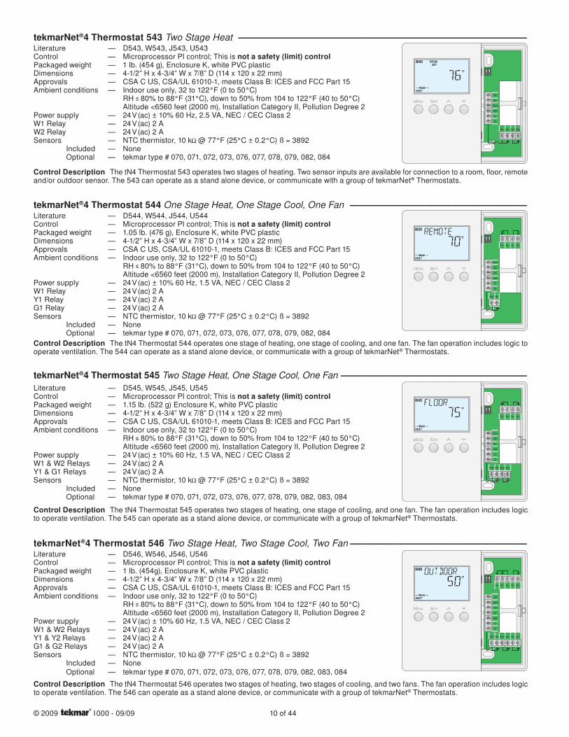
tekmarNet®4 Thermostat 543 Two Stage Heat ―――――――――――――――――――――――――――――――Literature — D543, W543, J543, U543Control — Microprocessor PI control; This is not a safety (limit) controlPackaged weight — 1 lb. (454 g), Enclosure K, white PVC plasticDimensions — 4-1/2” H x 4-3/4” W x 7/8” D (114 x 120 x 22 mm)Approvals — CSA C US, CSA/UL 61010-1, meets Class B: ICES and FCC Part 15Ambient conditions — Indoor use only, 32 to 122°F (0 to 50°C) RH 80% to 88°F (31°C), down to 50% from 104 to 122°F (40 to 50°C) Altitude <6560 feet (2000 m), Installation Category II, Pollution Degree 2Power supply — 24 V (ac) ± 10% 60 Hz, 2.5 VA, NEC / CEC Class 2W1 Relay — 24 V (ac) 2 AW2 Relay — 24 V (ac) 2 ASensors — NTC thermistor, 10 k @ 77°F (25°C ± 0.2°C) ß = 3892 Included — None Optional — tekmar type # 070, 071, 072, 073, 076, 077, 078, 079, 082, 084
Control Description The tN4 Thermostat 543 operates two stages of heating. Two sensor inputs are available for connection to a room, floor, remote and/or outdoor sensor. The 543 can operate as a stand alone device, or communicate with a group of tekmarNet® Thermostats.
tekmarNet®4 Thermostat 544 One Stage Heat, One Stage Cool, One Fan ―――――――――――――――――――Literature — D544, W544, J544, U544Control — Microprocessor PI control; This is not a safety (limit) controlPackaged weight — 1.05 lb. (476 g), Enclosure K, white PVC plasticDimensions — 4-1/2” H x 4-3/4” W x 7/8” D (114 x 120 x 22 mm)Approvals — CSA C US, CSA/UL 61010-1, meets Class B: ICES and FCC Part 15Ambient conditions — Indoor use only, 32 to 122°F (0 to 50°C) RH 80% to 88°F (31°C), down to 50% from 104 to 122°F (40 to 50°C) Altitude <6560 feet (2000 m), Installation Category II, Pollution Degree 2Power supply — 24 V (ac) ± 10% 60 Hz, 1.5 VA, NEC / CEC Class 2W1 Relay — 24 V (ac) 2 AY1 Relay — 24 V (ac) 2 AG1 Relay — 24 V (ac) 2 ASensors — NTC thermistor, 10 k @ 77°F (25°C ± 0.2°C) ß = 3892 Included — None Optional — tekmar type # 070, 071, 072, 073, 076, 077, 078, 079, 082, 084Control Description The tN4 Thermostat 544 operates one stage of heating, one stage of cooling, and one fan. The fan operation includes logic to operate ventilation. The 544 can operate as a stand alone device, or communicate with a group of tekmarNet® Thermostats.
tekmarNet®4 Thermostat 545 Two Stage Heat, One Stage Cool, One Fan ――――――――――――――――――――Literature — D545, W545, J545, U545Control — Microprocessor PI control; This is not a safety (limit) controlPackaged weight — 1.15 lb. (522 g) Enclosure K, white PVC plasticDimensions — 4-1/2” H x 4-3/4” W x 7/8” D (114 x 120 x 22 mm)Approvals — CSA C US, CSA/UL 61010-1, meets Class B: ICES and FCC Part 15Ambient conditions — Indoor use only, 32 to 122°F (0 to 50°C) RH 80% to 88°F (31°C), down to 50% from 104 to 122°F (40 to 50°C) Altitude <6560 feet (2000 m), Installation Category II, Pollution Degree 2Power supply — 24 V (ac) ± 10% 60 Hz, 1.5 VA, NEC / CEC Class 2W1 & W2 Relays — 24 V (ac) 2 AY1 & G1 Relays — 24 V (ac) 2 ASensors — NTC thermistor, 10 k @ 77°F (25°C ± 0.2°C) ß = 3892 Included — None Optional — tekmar type # 070, 071, 072, 073, 076, 077, 078, 079, 082, 083, 084
Control Description The tN4 Thermostat 545 operates two stages of heating, one stage of cooling, and one fan. The fan operation includes logic to operate ventilation. The 545 can operate as a stand alone device, or communicate with a group of tekmarNet® Thermostats.
Y1 Rc G1 G1
R
C
tN4
S1
S2
Com
W1Rh1 Rh2 W2
Y1 Rc G1 G1
R
C
tN4
S1
S2
Com
W1Rh1
tekmarNet®4 Thermostat 546 Two Stage Heat, Two Stage Cool, Two Fan ―――――――――――――――――――Literature — D546, W546, J546, U546Control — Microprocessor PI control; This is not a safety (limit) controlPackaged weight — 1 lb. (454g), Enclosure K, white PVC plasticDimensions — 4-1/2” H x 4-3/4” W x 7/8” D (114 x 120 x 22 mm)Approvals — CSA C US, CSA/UL 61010-1, meets Class B: ICES and FCC Part 15Ambient conditions — Indoor use only, 32 to 122°F (0 to 50°C) RH 80% to 88°F (31°C), down to 50% from 104 to 122°F (40 to 50°C) Altitude <6560 feet (2000 m), Installation Category II, Pollution Degree 2Power supply — 24 V (ac) ± 10% 60 Hz, 1.5 VA, NEC / CEC Class 2W1 & W2 Relays — 24 V (ac) 2 AY1 & Y2 Relays — 24 V (ac) 2 AG1 & G2 Relays — 24 V (ac) 2 ASensors — NTC thermistor, 10 k @ 77°F (25°C ± 0.2°C) ß = 3892 Included — None Optional — tekmar type # 070, 071, 072, 073, 076, 077, 078, 079, 082, 083, 084
Control Description The tN4 Thermostat 546 operates two stages of heating, two stages of cooling, and two fans. The fan operation includes logic to operate ventilation. The 546 can operate as a stand alone device, or communicate with a group of tekmarNet® Thermostats.
Y2 Y1 Rc G1 G1
W1Rh1 Rh2 W2 G2 G2
R
C
tN4
S1
S2
Com
S3
W1Rh1 Rh2 W2
R
C
tN4
Com
S1
S2

11 of 44 © 2009 I 000 - 09/09
tN4 Module Functions 420 421 422 423Number of Boilers 1 1 1 2Modulating Boiler •• •• ••On-Off Boiler •• •• •• ••Number of Water Temperatures 1 1 2* 4*Number of Mixing Temperatures 1 1/2* 3*
Boiler OperationBoiler Outdoor Reset •• •• ••Boiler Load Reset •• •• ••Boiler Auto Differential •• •• •• ••External Multiple Boiler Control •• •• ••
DHW OperationDHW Priority •• •• ••DHW through Pump •• •• ••DHW through Valve •• ••
Setpoint OperationSetpoint Priority •• •• ••
Mixing OperationMixing Outdoor Reset •• •• ••Variable Speed Output •• •• ••*Floating Action Output •• •• ••*Boiler Return Protection •• •• ••System Maximum Supply •• •• ••
General OperationIndoor Temperature Feedback •• •• •• ••Warm Weather Shut Down •• •• •• ••Exercising •• •• •• ••Access Levels •• •• •• ••Auto Test •• •• •• ••Maxheat •• •• •• ••Flushing •• •• ••
* Each mixing water temperature requires a Mixing Expansion Module 440, 441 or 444.
tekmarNet®4 (tN4) Outdoor Reset ModulestN4 Outdoor Reset Modules provide central intelligence for HVAC systems. These modules calculate the ideal supply water temperatures for every day of the year using a combination of outdoor reset and indoor temperature feedback. Through two-way communication, the Outdoor Reset Module collects information from every tekmarNet® device, utilizing it to maximize system efficiency, increase equipment lifespan & provide the highest level of comfort possible.
Select an Outdoor Reset Module to match boiler, mixing, DHW & setpoint requirements. Install the module in an enclosure with a Zone or Power Manager.
Zone or Power Manager
Outdoor Reset
Module
Boiler Reset Module 420 One tN4, Boiler, DHW & Setpoint ――――――――――――――――――――――――――Literature — D420, W420, J420, D070Control — Microprocessor PID control; This is not a safety (limit) control Packaged weight — 1.59 lb. (720 g)Dimensions — 3-5/8” H x 5-3/8” W x 9/16” D (92 x 137 x 14 mm)Approvals — CSA C US, CSA/UL 61010-1, meets Class B: ICES and FCC Part 15Ambient conditions — Indoor use only, 32 to 122°F (0 to 50°C). RH 80% to 88°F (31°C), down to 50% from 104 to 122°F (40 to 50°C) Altitude <6560 feet (2000 m), Installation Category II, Pollution Degree 2Power Supply — Provided by interconnected Zone ManagerDHW Pump Relay — 115 V (ac) 5 APrimary Pump Relay — 115 V (ac) 5 ACombined Load — 10 A Maximum (for DHW and Primary Pump)DHW Zone Valve — 24 V (ac) 8 VA MaximumModulation Output — 0-10 V (dc) Minimum 2500 Boiler Relay — 115 V (ac) 5 ADemands — 20-260 V (ac) / 0.1 VA @ 24 VSensors — NTC thermistor, 10 k @ 77°F (25°C ± 0.2°C) ß=3892 Included — Outdoor Sensor 070 and 1 Universal Sensor 071
Control Description The Boiler Reset Module 420 provides outdoor reset to a hydronic heating system in order to maximize comfort and efficiency. The 420 can operate a single on / off boiler or a single modulating boiler. The 420 can override the outdoor reset water temperature to provide Domestic Hot Water or Setpoint operations.
51 52 53 54 55 56 57 58 60 61 62 63 64
Boiler DHW Setpoint C
59
C Com Boil OutVlvDemand Demand 24 V (ac) DHW
R
65
+Mod (dc)
–
DHW Primary
10 Amax.66 67 68 69
NPump NPump
tN4
H7006B
Boil On-Off / ModOff / tekmar Stager
PoweredOutput 1 VA
DHW Valve:24 V (ac) 8 VA
Made in Canada
Meets Class B: CanadianICES & FCC Part 15
Test
Boiler Reset Module 420
Item
Menu
tektra 991-01
Demands: 20 - 260 V (ac)
Relay Rating: 115 V (ac) 5 A
/
Do not apply power
© 2009 I 000 - 09/09 12 of 44
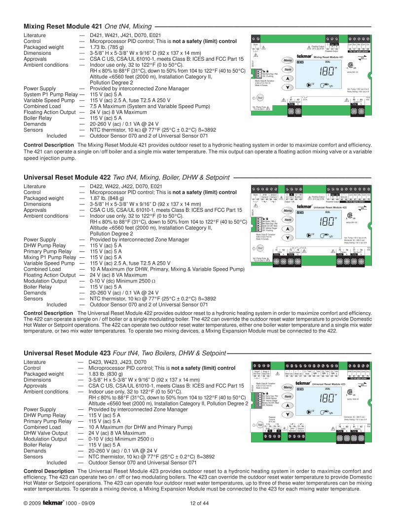
Mixing Reset Module 421 One tN4, Mixing ―――――――――――――――――――――――――――――――――Literature — D421, W421, J421, D070, E021Control — Microprocessor PID control; This is not a safety (limit) controlPackaged weight — 1.73 lb. (785 g)Dimensions — 3-5/8” H x 5-3/8” W x 9/16” D (92 x 137 x 14 mm)Approvals — CSA C US, CSA/UL 61010-1, meets Class B: ICES and FCC Part 15Ambient conditions — Indoor use only, 32 to 122°F (0 to 50°C). RH 80% to 88°F (31°C), down to 50% from 104 to 122°F (40 to 50°C) Altitude <6560 feet (2000 m), Installation Category II, Pollution Degree 2Power Supply — Provided by interconnected Zone ManagerSystem P1 Pump Relay — 115 V (ac) 5 AVariable Speed Pump — 115 V (ac) 2.5 A, fuse T2.5 A 250 VCombined Load — 7.5 A Maximum (System and Variable Speed Pump)Floating Action Output — 24 V (ac) 8 VA MaximumBoiler Relay — 115 V (ac) 5 ADemands — 20-260 V (ac) / 0.1 VA @ 24 VSensors — NTC thermistor, 10 k @ 77°F (25°C ± 0.2°C) ß=3892 Included — Outdoor Sensor 070 and 2 of Universal Sensor 071
Control Description The Mixing Reset Module 421 provides outdoor reset to a hydronic heating system in order to maximize comfort and efficiency. The 421 can operate a single on / off boiler and a single mix water temperature. The mix output can operate a floating action mixing valve or a variable speed injection pump.
Universal Reset Module 422 Two tN4, Mixing, Boiler, DHW & Setpoint ―――――――――――――――――――――Literature — D422, W422, J422, D070, E021Control — Microprocessor PID control; This is not a safety (limit) controlPackaged weight — 1.87 lb. (848 g)Dimensions — 3-5/8” H x 5-3/8” W x 9/16” D (92 x 137 x 14 mm)Approvals — CSA C US, CSA/UL 61010-1, meets Class B: ICES and FCC Part 15Ambient conditions — Indoor use only, 32 to 122°F (0 to 50°C). RH 80% to 88°F (31°C), down to 50% from 104 to 122°F (40 to 50°C) Altitude <6560 feet (2000 m), Installation Category II, Pollution Degree 2Power Supply — Provided by interconnected Zone ManagerDHW Pump Relay — 115 V (ac) 5 APrimary Pump Relay — 115 V (ac) 5 AMixing P1 Pump Relay — 115 V (ac) 5 AVariable Speed Pump — 115 V (ac) 2.5 A, fuse T2.5 A 250 VCombined Load — 10 A Maximum (for DHW, Primary, Mixing & Variable Speed Pump)Floating Action Output — 24 V (ac) 8 VA MaximumModulation Output — 0-10 V (dc) Minimum 2500 Boiler Relay — 115 V (ac) 5 ADemands — 20-260 V (ac) / 0.1 VA @ 24 VSensors — NTC thermistor, 10 k @ 77°F (25°C ± 0.2°C) ß=3892 Included — Outdoor Sensor 070 and 2 of Universal Sensor 071
Control Description The Universal Reset Module 422 provides outdoor reset to a hydronic heating system in order to maximize comfort and efficiency. The 422 can operate a single on / off boiler or a single modulating boiler. The 422 can override the outdoor reset water temperature to provide Domestic Hot Water or Setpoint operations. The 422 can operate two outdoor reset water temperatures, either one boiler water temperature and a single mix water temperature, or two mix water temperatures. To operate two mixing devices, a Mixing Expansion Module must be connected to the 422.
51 52 53 54 55 56 57 58 59 60 61 62 63 64 65
Boiler DHW Setpoint C C2 tN4 C Com Boil Mix Com Out+Opn ClsDemand Demand 24 V (ac) Boil/Mix2 R R Mod (dc)
R
66 67 68 69 70
–
Primary Mix Sys P1
10 Amax.75 76 77 78
N NDHW Variable Speed
71 72 73 74
Pump Pump NPump NPump
tN4H7008B
tN4 Boiler / Mix 2Boil Sens Sup / RetBoiler On-Off / ModOff / tekmar StagerOff / Flushing
Powered OutputOutput 1 VA
Floating Output:24 V (ac) 8 VA
Made in Canada
Meets Class B: CanadianICES & FCC Part 15
Test
Var. Pump FuseT2.5 A 250 V
Universal Reset Module 422
Item
Menu
tektra 991-03
Var. Pump: 115 V (ac) 2.5 A
Demands: 20 - 260 V (ac)
Relay Rating: 115 V (ac) 5 A
/
Do not apply power
2.5 A
51 52 55 56 57
Boiler
5453
C Com Boil MixClsOpn
58RR
59
Com Out
60
Variable Speed2.5 A
7.5 Amax61 62
NPump
tN4
Boil Sens Sup / RetOff / Flushing
Powered Output
Floating Output:24 V (ac) 8 VA
Made in Canada
Meets Class B: CanadianICES & FCC Part 15
Test
Mixing Reset Module 421
Item
Menu
tektra 991-02
Var. Pump: 115V (ac) 2.5 A
Relay Rating: 115V (ac) 5 A
/
Do not apply power
System P163 64
NPump
Var. Pump FuseT2.5 A 250 V
H7007B
Universal Reset Module 423 Four tN4, Two Boilers, DHW & Setpoint ――――――――――――――――――――――Literature — D423, W423, J423, D070Control — Microprocessor PID control; This is not a safety (limit) controlPackaged weight — 1.83 lb. (830 g)Dimensions — 3-5/8” H x 5-3/8” W x 9/16” D (92 x 137 x 14 mm)Approvals — CSA C US, CSA/UL 61010-1, meets Class B: ICES and FCC Part 15Ambient conditions — Indoor use only, 32 to 122°F (0 to 50°C). RH 80% to 88°F (31°C), down to 50% from 104 to 122°F (40 to 50°C) Altitude <6560 feet (2000 m), Installation Category II, Pollution Degree 2Power Supply — Provided by interconnected Zone ManagerDHW Pump Relay — 115 V (ac) 5 APrimary Pump Relay — 115 V (ac) 5 ACombined Load — 10 A Maximum (for DHW and Primary Pump)DHW Valve Output — 24 V (ac) 8 VA MaximumModulation Output — 0-10 V (dc) Minimum 2500 Boiler Relay — 115 V (ac) 5 ADemands — 20-260 V (ac) / 0.1 VA @ 24 VSensors — NTC thermistor, 10 k @ 77°F (25°C ± 0.2°C) ß=3892 Included — Outdoor Sensor 070 and Universal Sensor 071
Control Description The Universal Reset Module 423 provides outdoor reset to a hydronic heating system in order to maximize comfort and efficiency. The 423 can operate two on / off or two modulating boilers. The 423 can override the outdoor reset water temperature to provide Domestic Hot Water or Setpoint operations. The 423 can operate four outdoor reset water temperatures, up to three of these water temperatures can be mixing water temperatures. To operate a mixing device, a Mixing Expansion Module must be connected to the 423 for each mixing water temperature.
50 51 52 53
Stage1/ Stage 2/ Boil Enbl Setp Enbl
75 76 77 78
Demand DemandDHW Setpoint
54 55
DHW Primary
10 Amax79 80 81 82
NPump NPump
tN4Made in Canada
8 VA 1 VA
Boil Sens Sup / Ret
H7010A
Off / DHW SensorOff / tekmar StagerBoilers On-Off / ModOff / Rotation
Meets Class B: CanadianICES & FCC Part 15
PoweredOutputs24 V (ac)
Universal Reset Module 423
Item
Menu
tektra 1006-01
Demands: 20 - 260 V (ac)
Relay Rating: 115 V (ac) 5 A
71 72 73 74DHW 24 V (ac)
/
57 58 59 60 6156
C
C
tN4Mod2 (dc)Mod1 (dc)
6564
C3C1+ –
C
+ – tN4
62 63
C2 tN4 tN4
66 67
DHW ComBoiler
68 69
Boil Com
70
Out
Do not apply power
Test
1 2 3
Vlv R

13 of 44 © 2009 I 000 - 09/09
Functions 440 441 444Number of Water Temperatures 1 1 1
Mixing Operation
Variable Speed Output •• ••Floating Action Output •• ••Actuator Motor ••Analog 0-20 mA or 4-20 mA ••Analog 0-10 V (dc) or 2-10 V (dc) ••Boiler Return Protection •• •• ••System Maximum Supply •• •• ••
General Operation
Exercising •• •• ••Maxheat •• •• ••
Mixing Expansion Module 440 Variable Speed / Floating Action ――――――――――――――――――――――――Literature — D440, W440, J440, D070, E021Control — Microprocessor PID control; This is not a safety (limit) controlPackaged weight — 1.16 lb. (526 g)Dimensions — 3-5/8” H x 5-3/8” W x 9/16” D (92 x 137 x 14 mm)Approvals — CSA C US, CSA/UL 61010-1, meets Class B: ICES and FCC Part 15Ambient conditions — Indoor use only, 32 to 122°F (0 to 50°C). RH 80% to 88°F (31°C), down to 50% from 104 to 122°F (40 to 50°C) Altitude <6560 feet (2000 m), Installation Category II, Pollution Degree 2Power Supply — Provided by interconnected Zone ManagerSystem P1 Pump Relay — 115 V (ac) 5 AVariable Speed Pump — 115 V (ac) 2.5 ACombined Load — 7.5 A Maximum (System and Variable Speed Pump)Floating Action Output — 24 V (ac) 8 VA MaximumSensors — NTC thermistor, 10kΩ @ 77°F (25°C ± 0.2°C) ß=3892 Included — Universal Sensor 071
Control Description The Mixing Expansion Module 440 provides a system pump output and a single mixing output for either a variable speed injection pump or floating action mixing valve. The 440 cannot operate by itself and requires the use of a tN4 Outdoor Reset Module that is capable of operating a mixing expansion module. The 440 also requires installation in an enclosure provided by a tN4 Zone or Power Manager.
51 52 54 55
C Com MixRR
Opn
53
Cls
N NVariable Speed System
56 57 58 59
Pump Pump
tN4
Variable / Floating
Powered Output
Floating Output:24 V (ac) 8 VA
Meets Class B: CanadianICES & FCC Part 15Made in Canada
Var. Pump FuseT2.5 A 250 V
7.5 A (max)2.5 A
Mixing Expansion Module 440
tektra 1000-02
Var. Pump: 115 V (ac) 2.5 A
Relay Rating: 115 V (ac) 5 A
Power
System Pump
Mix % Out
Open
Close
No power
H7009B
tekmarNet®4 (tN4) Mixing Expansion ModulesExpand the number of mixed temperatures in a tekmarNet® system by connecting Mixing Expansion Modules to a Universal Reset Module 422 or 423.
440 444 441
Mixing Expansion Module 441 Actuating Motor ―――――――――――――――――――――――――――――――Literature — D441, W441, J441, D070Control — Microprocessor PID control; This is not a safety (limit) control Packaged weight — 1.53 lb. (694 g)Dimensions — 3-1/2” H x 3” W x 3-1/2” D (90 x 75 x 90 mm)Approvals — CSA C US, CSA/UL 61010-1, meets Class B: ICES and FCC Part 15Ambient conditions — Indoor use only, 32 to 122°F (0 to 50°C). 92% RH up to 104°F (40°C), 50% RH if > 104°F (40°C) Altitude <9840 feet (3000 m), Installation Category II, Pollution Degree 2Power Supply — 24 V (ac) 50/60 Hz, 4 VAControl Signal — tN4 BusSystem Pump — 24 V (ac), 2 AAngle of Rotation — 90° rotation, non-adjustableRunning Time — 105 seconds (60 Hz), 126 seconds (50 Hz)Maximum Torque — 6 N•m (53 in•lb)Sensors — NTC thermistor, 10kΩ @ 77°F (25°C ± 0.2°C) ß=3892 Included — 1 Universal Sensor 082Other Included — 2 of anti-rotation stops 1 of coupler with white arrow 1 of coupler with red arrow 1 of hand wheel with red stripe
Control Description The Mixing Expansion Module 441 is designed to operate any of the tekmar 3-way and 4-way brass mixing valves from type 710 through type 724. The 441 provides 6 N•m (53 in•lbs) of torque over a 90° rotation. The 441 is controlled through digital communication on tekmarNet®4 systems. The 441 requires the use of a tN4 Outdoor Reset Module that includes a mix temperature bus.
Power
tN4
SystemPump
Mixing Expansion Module 441
Made In Canada
Actuating Motor24 V (ac) 50/60 Hz 4 VA 105 sSystem Pump: 24 V (ac) 2 A
tektra 1010-01
H1212A

© 2009 I 000 - 09/09 14 of 44
Mixing Expansion Module 444 Variable Speed / Floating Action / Modulating ――――――――――――――――――Literature — D444, W444, J444, D001, D070Control — Microprocessor PID control; This is not a safety (limit) control Packaged weight — 1.14 lb. (520 g)Enclosure — D Enclosure, white PVC plasticDimensions — 4-3/4” H x 2-7/8” W x 1-7/8” D (120 x 74 x 48 mm)Approvals — CSA C US, CSA/UL 61010-1, meets Class B: ICES and FCC Part 15Ambient conditions — Indoor use only, 36 to 122°F (2 to 50°C) 92% RH up to 104°F (40°C), 50% RH if > 104°F (40°C) Altitude <9840 feet (3000 m), Installation Category II, Pollution Degree 2Power Supply — 24 V (ac) ±10% 50/60 Hz 4 VA standby, 56 VA fully loadedSystem Pump Relay (front) — 24 V (ac) 2ASystem Pump Relay (back) — 120 V (ac) 5AVariable Speed Output — 120 V (ac) 2.4 A, internal overload circuit T2.5 A 250 VFloating Output — 24 V (ac) 8 VA maximum, triac output, minimum 0.6 VAModulating Output (voltage) — 0 or 2-10 V (dc), minimum 10kΩModulating Output (current) — 0 or 4-20 mA, maximum 1kΩSensors — NTC thermistor, 10kΩ @ 77°F (25°C ± 0.2°C) ß=3892 Included — 1 Universal Sensor 082
Control Description The Mixing Expansion Module 444 provides six options for operating a variable speed injection pump, a floating action actuator, or an analog 0-10 V (dc), 2-10 V (dc), 0-20 mA, or 4-20 mA signal. The 444 also provides an output for a system pump. The 444 cannot operate alone and requires the use of a tN4 Outdoor Reset Module that is capable of operating a Mixing Expansion Module.
Power: 24 V (ac) ±10% 50/60 Hz 4 VA, 56 VA full load
Sys Pmp (Rear): 120 V (ac) 5 A 1/3 hp
Sys Pmp (Front): 24V (ac) 2 A
Var. Pmp: 120 V (ac) 2.4 A 1/6 hp
Floating Output: 24 V (ac) 8 VAmin. 0.6 VA
Mixing Expansion Module 444Variable Speed / Floating Action / Modulating
0-10 V (dc)Actuator
2-10 V (dc)Variable
H30
09A
Mix % Out
tektra 1018-01
tN4
Power
System Pump
For product instructions,see brochure.
Made in CanadaSignal wiring
must be rated atleast 300V / 90°CC
ut fo
r m
A o
utpu
t
5R
6R
41tN4
7Mod
+
8Com
9Mix
Power ClsOpnSysPmp
2C
3R
No Power
Dat
e C
ode
Meets Class B: CanadianICES, FCC Part 15
tN4 Zone Manager 335 Six Zone Valves ――――――――――――――――――――――――――――――――――Literature — D335, W335, J335Packaged weight — 5.46 lb. (2480 g)Enclosure — L enclosure, blue PC+ABS plastic with metal top and bottom conduit connection wallsDimensions — 8-1/16” H x 11-1/8” W x 2-15/16” D (204 x 282 x 74 mm)Approvals — CSA C US, CSA/UL 61010-1, meets Class B: ICES and FCC Part 15Ambient conditions — Indoor use only, 32 to 122°F (0 to 50°C). RH 80% to 88°F (31°C), down to 50% from 104 to 122°F (40 to 50°C), Altitude <6560 feet (2000 m) Installation Category II, Pollution Degree 2Power Supply — 115 V (ac) +/- 10% 60 Hz 12 ATransformer Power Available — 24 V (ac) 50 VA, fuse T2.5 A 250 VZone Group Pump A Relay — 115 V (ac) 5 ACombined Load on Input Power — 11.5 A MaximumGroup Pump A Demand — 24 V (ac) < 0.1 VA
Control Description The Zone Manager 335 is designed to simplify the wiring between tN4 thermostats and zone valves. The 335 has an internal transformer that supplies power to the tN4 thermostats and connected zone valves.
Zone Manager 335
Meets Class B:Canadian ICES &FCC Part 15
Made in Canada
Zone A1
Zone A2
Power
Zone Group Pump A
Zone A3
Zone A4
Zone A5
Zone A6
tN4
tektra 996-01
For product instructions, see brochure
Input Power: 115 V (ac) ±10% 60 Hz 12 A
Relay Rating: 115 V (ac) 5 A
All Loads Using Input Power: 11.5 ACaution! Disconnect AllPower before Opening
Limited power available, see wiring brochure
For product literature:
www.tekmarcontrols.com
1 2 3 4 5 6 7 8 9 10 11 12 13 14 15 16 20
H70
03B
32 33 34 35 36 37 38 39 40 41 42 43
17 18 19 21 22 23 24 25 26 27
24 V (ac) Fuse: T2.5 A 250 V
28 29 30 31
On/Off
Zone GroupPump A Delay
Zone GroupPump A
A1A2A3A4A5A6A1A2A3A4A5A6
tN4 C C CW WR RPmp tN4 tN4 C WRtN4 C WR RtN4 C WtN4 RC WtN4
Input Power Zone Group Zone A1 Zone A2 Zone A3 Zone A4 Zone A5 Zone A6
Zn Grp A A tNt Zone A1 tNt Zone A2 tNt Zone A3 tNt Zone A4 tNt Zone A5 tNt Zone A6
NL NPmp A C Vlv C Vlv C Vlv C Vlv C Vlv C Vlv
Supply /signal wires 90°C min.
tekmarNet®4 (tN4) Zone & Power ManagerstN4 Zone and Power Managers are pre-installed in an easy to wire ‘L’ Enclosure. With point to point wiring and built-in fuse protection, zoning a tN4 system is easy. Select a Zone or Power Manager based on the number and type of zoning devices required.
tN4 Zone & Power Manager Functions 335 336 337 345 346Power for Reset Module •• •• •• •• ••Number of Zones 6 4 3+3 1 3
Water Temperatures 1 1 2 1 3
Zone Valves •• ••Zone Pumps •• •• ••Zone Group Pump 1 1 2
Zone Group Pump Delay •• ••Power Available with expansion module without expansion module
40 VA52 VA
15 VA27 VA
42 VA54 VA
38 VA50 VA
On-Board Fuse •• •• •• •• ••

15 of 44 © 2009 I 000 - 09/09
tN4 Zone Manager 336 Four Zone Pumps ―――――――――――――――――――――――――――――――――Literature — D336, W336, J336Packaged weight — 4.86 lb. (2000 g)Enclosure — L enclosure, blue PC+ABS plastic with metal top and bottom conduit connection wallsDimensions — 8-1/16” H x 11-1/8” W x 2-15/16” D (204 x 282 x 74 mm)Approvals — CSA C US, CSA/UL 61010-1, meets Class B: ICES and FCC Part 15Ambient conditions — Indoor use only, 32 to 122°F (0 to 50°C). RH 80% to 88°F (31°C), down to 50% from 104 to 122°F (40 to 50°C), Altitude <6560 feet (2000 m) Installation Category II, Pollution Degree 2Power Supply — 115 V (ac) +/- 10% 60 Hz 12 ATransformer Power Available — 24 V (ac) 24 VA, fuse T1.25 A 250 VZone Group Pump A Relay — 115 V (ac) 5 AZone Pump Relays — 115 V (ac) 5 ACombined Load on Input Power — 11.7 A MaximumCombined Load on Zone Power — 12 A MaximumGroup A Pump Demand — 24 V (ac) < 0.1 VA
Control Description The Zone Manager 336 is designed to simplify the wiring between tN4 thermostats and zone pumps. The 336 has an internal transformer that supplies power to the tN4 Thermostats.
Zone Manager 336
Meets Class B: CanadianICES & FCC Part 15Made in CanadaSupply /signal wires 90°C min.
Zone A1
Zone A2
Power
Zone Group Pump A
Zone A3
Zone A4
tN4
tektra 997-01
Input Power: 115 V (ac) ±10% 60 Hz, 12 A
Relay Rating: 115 V (ac) 5 A
All Loads Using Input Power: 11.7 A
Zone Power: 115 V (ac) ±10% 60 Hz, 12 A
For product instructions, see brochureCaution! Disconnect AllPower before Opening
Limited power available, see wiring brochure
For product literature:
www.tekmarcontrols.com
1 2 3 4 5 6 7 8 9 10 11 12 13 14 15 16 17 18 19
24 V (ac) Fuse: T1.25 A 250 V
On/Off
tN4 C C CW WR RPmp tN4 tN4 C WRtN4 C WRtN4Zn Grp A A tNt Zone A1 tNt Zone A2 tNt Zone A3 tNt Zone A4
20 21 22 23Input Power Zone Group
NL NPmp A
30 31 32 33Zone A3 Zone A4
NPump NPump
26 27 28 29Zone A1 Zone A2
NPump NPump
24 25Zone Power
NL
Zone GroupPump A
A1A2A3A4
H7004B
tN4 Dual Zone Manager 337 Three + Three Zone Valves ―――――――――――――――――――――――――――Literature — D337, W337, J337Packaged weight — 5.47 lb. (2480 g)Enclosure — L enclosure, blue PC+ABS plastic with metal top and bottom conduit connection wallsDimensions — 8-1/16” H x 11-1/8” W x 2-15/16” D (204 x 282 x 74 mm)Approvals — CSA C US, CSA/UL 61010-1, meets Class B: ICES and FCC Part 15Ambient conditions — Indoor use only, 32 to 122°F (0 to 50°C). RH 80% to 88°F (31°C), down to 50% from 104 to 122°F (40 to 50°C), Altitude <6560 feet (2000 m) Installation Category II, Pollution Degree 2Power Supply — 115 V (ac) +/- 10% 60 Hz 15.5 A, fuse T15 A 250 VTransformer Power Available — 24 V (ac) 50 VA, fuse T2.5 A 250 VZone Group Pump A Relay — 115 V (ac) 5 AZone Group Pump B Relay — 115 V (ac) 5 ACombined Load on Input Power — 15 A MaximumGroup Pump B Demand — 24 V (ac) < 0.1 VA
Control Description The Dual Zone Manager 337 is designed to simplify the wiring between tN4 thermostats and zone valves. The 337 has an internal transformer that supplies power to the tN4 thermostats and connected zone valves. The 337 has two tN4 buses with three zones each. The two buses allow the 337 to operate zones on two different water temperatures.
Dual Zone Manager 337
Meets Class B: CanadianICES & FCC Part 15
Made inCanadaPower Fuse: T15 A 250 V
15 A
Zone A1
Zone A2
Power
Zone Group Pump A
Zone A3
Zone B1
Zone B2
Zone B3
tN4
tektra 996-02
For product instructions, see brochure
Input Power: 115 V (ac) ±10% 60 Hz, 15.5 A
Relay Rating: 115 V (ac) 5 A
All Loads Using Input Power: 15 A
Caution! Disconnect AllPower before Opening
Limited power available, see wiring brochure
For product literature:
www.tekmarcontrols.com
Zone Group Pump B
1 2 3 4 5 6 7 8 9 10 11 12 13 14 15 16 20
H70
05B32 33 34 35 36 37 38 39 40 41 42 43
17 18 19 21 22 23 24 25 26 27
24 V (ac) Fuse: T2.5 A 250 V
28 29 30 31
On/Off
Zone GroupPump A Delay
Zone GroupPump A
Zone GroupPump B Delay
Zone GroupPump B
A1A2A3B1B2B3A1A2A3B1B2B3
tN4 C C CW WR RPmp tN4 tN4 C WRtN4 C WR RtN4 C WtN4 RC WtN4
Input Power Zn Grp Zn Grp Zone A1 Zone A2 Zone A3 Zone B1 Zone B2 Zone B3
Zn Grp B B tNt Zone A1 tNt Zone A2 tNt Zone A3 tNt Zone B1 tNt Zone B2 tNt Zone B3
NL Pmp A Pmp B C Vlv C Vlv C Vlv C Vlv C Vlv C Vlv
Supply /signal wires 90°C min.
Power Manager 345 One Auxiliary Pump ――――――――――――――――――――――――――――――――――Literature — D345, W345, J345Packaged weight — 3.5 lbs (1610 g)Enclosure — L enclosure, blue PC+ABS plastic with metal top and bottom conduit connection wallsDimensions — 8-1/16” H x 11-1/8” W x 2-15/16” D (204 x 282 x 74 mm)Approvals — CSA C US, CSA/UL 61010-1, meets Class B: ICES and FCC Part 15Ambient conditions — Indoor use only, 32 to 122°F (0 to 50°C) RH 80% to 88°F (31°C), down to 50% from 104 to 122°F (40 to 50°C), Altitude <6560 feet (2000 m) Installation Category II, Pollution Degree 2Power Supply — 115 V (ac) +/- 10% 60 Hz 12 ATransformer Power Available — 24 V (ac) 56 VA, fuse T2.5 A 250 VAuxiliary Pump Input — 24 V (ac) < 0.5 VAAuxiliary Pump Relay — 115 V (ac) 5Combined Load — 11.5 A Maximum
Control Description The Power Manager 345 has an internal transformer that can be used to power a Reset Module 420, 421, 422, or 423 through a connector plug. The 345 can also provide power to devices such as thermostats, setpoint controls and mixing expansion modules via field wiring. A single tN4 bus input is available to allow Zone Managers and in some cases, Mixing Expansion Modules, to be connected.
Input Power7 8
NL
Power Manager 345
tektra 996-03
Aux Pump9 10
NPmp
For product instructions, see brochureInput Power: 115 V (ac) ±10% 60 Hz, 12 ARelay Rating: 115 V (ac) 5 AAll Loads Using Input Power: 11.5 A
For product literature:www.tekmarcontrols.com
Power
Aux Pump
Made in CanadaSupply/signal wires 90°C min.
Caution! Disconnect AllPower before Opening
24 V (ac) Fuse: T2.5 A 250 V
H7012A
C
5
Aux
1Pmp
4 6
R RtN4 C
2 31 24 V (ac)
Limited power available, see wiring brochure

© 2009 I 000 - 09/09 16 of 44
tN4 Zone Expansion Module 326 Three Zone Pumps ――――――――――――――――――――――――――――Literature — D326, W326, J326Packaged weight — 2.98 lb (1350 g)Dimensions — 3-5/8” H x 5-3/8” W x 9/16” D (92 x 137 x 14 mm)Approvals — CSA C US, CSA/UL 61010-1, meets Class B: ICES & FCC Part 15Ambient conditions — Indoor use only, 32 to 122°F (0 to 50°C), RH 80% to 88°F (31°C), down to 50% from 104 to 122°F (40 to 50°C) Altitude <6560 feet (2000 m), Installation Category II, Pollution Degree 2Power Supply — Provided by interconnected Zone ManagerZone Pump C1 Relay — 115 V (ac) 5 A 1/4 hp, pilot duty 240 VAZone Pump C2 Relay — 115 V (ac) 5 A 1/4 hp, pilot duty 240 VAZone Pump C3 Relay — 115 V (ac) 5 A 1/4 hp, pilot duty 240 VAZn Grp Pump C Relay — 115 V (ac) 5 A 1/4 hp, pilot duty 240 VACombined Relay Load — 10 A Maximum
Control Description The Zone Expansion Module 326 is designed to simplify the wiring between tN4 thermostats and zone pumps. The 326 supplies power to the tN4 thermostats and connected zone pumps.
N NZone C1 Zone C2
65 66 67 68
Pump Pump
tN4
Meets Class B: CanadianICES & FCC Part 15Made in Canada
10 A (max)
Zone Expansion Module 326
tektra 999-01
Relay Rating: 115 V (ac) 5 A
NZone C3
69 70
Pump NZone Group71 72
Pmp C
Power
Zone Group Pump C
Zone C1
Zone C2
Zone C3
51 52 53 54 55 56 57 58 59 60 61 62
C CW WR RtN4 tN4 C WRtN4tNt Zone C1 tNt Zone C2 tNt Zone C3
63 64
C tN4Zn Grp C
C1C2
On/Off
Zone GroupPump CC3
Limited power available, see wiring brochure
H7002B
tN4 Zone Expansion Module 325 Six Zone Valves ―――――――――――――――――――――――――――――Literature — D325, W325, J325Packaged weight — 1.15 lb. (521 g)Dimensions — 3-5/8” H x 5-3/8” W x 9/16” D (92 x 137 x 14 mm)Approvals — CSA C US, CSA/UL 61010-1, meets Class B: ICES & FCC Part 15Ambient conditions — Indoor use only, 32 to 122°F (0 to 50°C), RH 80% to 88°F (31°C), down to 50% from 104 to 122°F (40 to 50°C) Altitude <6560 feet (2000 m), Installation Category II, Pollution Degree 2Power Supply — Provided by interconnected Zone ManagerTransformer — 24 V (ac) 53 VA, fuse T2.5 A 250 VZn Grp Pump C Relay — 115 V (ac) 5 ACombined Relay Load — 5 A MaximumControl Description The Zone Expansion Module 325 is designed to simplify the wiring between tN4 thermostats and zone valves. The 325 has an internal transformer that supplies power to the tN4 thermostats and connected zone valves.
NZone Group89 90
Pmp C
tN4
Meets Class B:Canadian ICES &FCC Part 15
5 A (max)
Zone Expansion Module 325
tektra 998-01
Relay Rating: 115 V (ac) 5 A
24 V (ac) Fuse: T2.5 A 250 V
Power
Zone Group Pump C
H7001B
Zone C1
Zone C2
Zone C3
Zone C4
Zone C5
Zone C6
51 52 53 54 55 56 57 58 59 60 61 62
C CW WR RtN4 tN4 C WRtN4tNt Zone C1 tNt Zone C2 tNt Zone C3
63 64 65 66 67 68 69 70 71 72 73 74
C CW WR RtN4 tN4 C WRtN4tNt Zone C4 tNt Zone C5 tNt Zone C6
75 76
tN4C
Zn Grp C
C2C3
On/Off
Zone GroupPump C Delay
Zone GroupPump C
C4C5C6
C5C6C1
C1
C3C2
C4
Limited power available, see wiring brochure
77 78 79 80 81 82 83 84 85 86 87 88Zone C1 Zone C2 Zone C3 Zone C4 Zone C5 Zone C6C Vlv C Vlv C Vlv C Vlv C Vlv C Vlv Made in Canada
tN4 Zone Expansion Module Functions 325 326Number of Zones 6 3Number of Water Temperatures 1 1Zone Valves ••Zone Pumps ••Zone Group Pump 1 1Zone Group Pump Delay ••Available Power 53 VAOn-Board Fuse ••
Power Manager 346 Three Auxiliary Pumps, Four Demands ―――――――――――――――――――――――――Literature — D346, W346, J346Packaged weight — 3.5 lbs (1610 g)Enclosure — L enclosure, blue PC+ABS plastic with metal top and bottom conduit connection wallsDimensions — 8-1/16” H x 11-1/8” W x 2-15/16” D (204 x 282 x 74 mm)Approvals — CSA C US, CSA/UL 61010-1, meets Class B: ICES & FCC Part 15Ambient conditions — Indoor use only, 36 to 117°F (2 to 47°C), RH 92% to 104°F (40°C), 50% above 104°F (40°C), Altitude <6560 feet (2000 m), Installation Category II, Pollution Degree 2Power Supply — 115 V (ac) +/- 10% 60 Hz 12 ARelay Power — 115 V (ac) +/- 10% 60 Hz 10 AWire Rating — Installations up to 104°F (40°C) only require 90°C supply wiring, whereas environments of 105 to 117°F (41 to 47°C) require 105°C rated wiring.Max Low Voltage Load — 24 V (ac) 2.1 A 50 VA, Fuse: T2.5 A 250 VAuxiliary Pump Inputs — 24 V (ac), < 0.1 VAAuxiliary Pump Relays — 115 V (ac) 5 ABus Demands — 20 to 260 V (ac) 2 VA
Control Description The Power Manager 346 has an internal transformer that powers a tN4 System Control 420, 421, 422, or 423. The 346 also includes four on-off demand inputs that can be used to provide a tN4 communication message to activate the reset module. This allows the use of stand-alone thermostats with tN4 System Controls.
tektra 1019-01
1
Power Manager 346
For product literature:www.tekmarcontrols.com
Boiler Bus 0 Demand Power
Aux Pump 1
Aux Pump 2
Aux Pump 3
tN4
Bus 1 Demand
Bus 2 Demand
Bus 3 Demand
Meets Class B: CanadianICES & FCC Part 15
Caution! Disconnect AllPower before Opening
24 V (ac) Fuse: T2.5 A 250 V
H7
011
A
Relay Power27 28
NLAux Pump 229 30
NPmpAux Pump 331 32
NPmp
For product instructions, see brochureInput Power: 115 V (ac) ±10% 60 Hz, 12 AAll Loads Using Input Power: 11.5 ARelay Ratings: 115 V (ac) 5 ARelay Power: 115 V (ac) ±10% 60 Hz, 10 ADemands: 20 to 260 V (ac) 2 VA
Supply wires 90°C/105°CSee manual
Boil Bus 0
16 17Demand
Bus 3 Bus 2
18Dem DemDem
19
Bus 1
20 21Demand
227
tN4
5 6
tN4 C C
1 2Boil 0
11
tN4
9 102C C
15
tN4
13 143
ComAux
Pmp1
4
RR R R
3
Aux
Pmp2
8
Aux
Pmp3
12Limited power available, see wiring brochure
Room Occ
Room UnOcc
0Boil
1
2
3 1
3
11
9
7
5
12
10
8
6
4
2Sch
edul
eM
embe
r
Input Power23 24
NLAux Pump 125 26
NPmp
tekmarNet®4 (tN4) Zone Expansion ModulesZone Expansion Modules provide additional zoning for tekmarNet® systems. They are installed in the left hand side of a tN4 Zone or Power Manager enclosure.

17 of 44 © 2009 I 000 - 09/09
tN4 Wiring Center 315 Six Zone Valves ―――――――――――――――――――――――――――――――――――Literature — D315, Q315Packaged weight — 1.37 lbs (0.62 kgs)Enclosure — O-Enclosure, blue PC+ABS UL94-5VA plasticDimensions — 5.5” H x 5.5” W x 2.25” D (140 x 140 x 57 mm)Approvals — CSA C US, CSA 22.2 No. 24 and UL 873, meets class B: ICES & FCC Part 15Ambient conditions — Indoor use only, 32 to 122°F (0 to 50°C) RH 90% Non-condensingPower supply — 24 V (ac) ±10% 60 Hz, 98 VA max, Class 2Zone valve load — 24 V (ac) 2 A, maximum combined current (zones 1 to 4): 4 AEnd switch relay rating — 24 V (ac) 2 A
Control Description The tN4 Wiring Center 315 is designed to operate up to six zone valves in a hydronic heating system. It can be mounted near a remote zone manifold, providing a convenient location to wire both thermostats and zone valves. When combined with tekmarNet®4 Thermostats, all devices communicate to provide a synchronized end switch that reduces cycling of equipment.
Input Power: 24 V (ac) ±10% 60 Hz
98 VA Max, Class 2
Control Load: 2 VA
End Switch: 24 V (ac) 2 A
Zone Output: 2 A per zone
4 A (max) total
PowerZone 1
Zone 2
Zone 3
Zone 4
Zone 5
Zone 6
End Switch
C
Zone 2
WtN4 R C
Zone 3
WtN4 R C
Zone 4
WtN4 R
tN4 Wiring Center 315Six Zone Valves
WtN
4C
tN4
CX
Zone 1
Expansion
VlvC
Zone 1
VlvC
Zone 2
VlvC
Zone 3
VlvC
Zone 4
VlvC
Zone 5
VlvC
Zone 6
XC
Input Pow
er
RR
WtN
4C
Zon
e 5
RW
tN4
C
Zon
e 6
R
H8001
A
End S
witch
Made in Canada
tektra 1032-01
Use
at l
east
167
°F(7
5°C
) co
nduc
tors
tN4 Wiring Center Functions 315 316Number of Zone Valves 6Number of Zone Pumps 4tN4 Expansion Yes Yes
tN4 Wiring Center 316 Four Zone Pumps ――――――――――――――――――――――――――――――――――Literature — D316, Q316Packaged weight — 1.41 lbs (0.64 kgs)Enclosure — O-Enclosure, blue PC+ABS UL94-5VA plasticDimensions — 5.5” H x 5.5” W x 2.25” D (140 x 140 x 57 mm)Approvals — CSA C US, CSA 22.2 No. 24 and UL 873, meets class B: ICES & FCC Part 15Ambient conditions — Indoor use only, 32 to 122°F (0 to 50°C) RH 90% Non-condensingPower supply — 24 V (ac) ±10% 60 Hz, 100 VA max, Class 2Zone pump relays — 115 V (ac) 5 A 1/3 hpPump wire wall nuts — 300 V (ac) 20 AEnd switch relay — 24 V (ac) 2 AZone power input — 115 V (ac) 12 A maximum
Control Description The tN4 Wiring Center 316 is designed to operate up to four zone pumps in a hydronic heating system. It provides a convenient location to wire both thermostats and zone pumps. The 316 is optimized for use with tekmarNet®4 Thermostats. These thermostats communicate with the tN4 Wiring Center to provide a synchronized end switch that reduces cycling of equipment.
PowerZone 1
Zone 2
Zone 3
Zone 4
End Switch
C
Zone 2
WtN4 R C
Zone 3
WtN4 R C
Zone 4
WtN4 R
tN4 Wiring Center 316Four Zone Pumps
WtN
4C
tN4
C
Zone 1
Expansion
End S
witch
C
Input Pow
er
RR
H80
02A
XX
Input Power: 24 V (ac) ±10% 60 Hz
10 VA (100 VA max)
Class 2
End Switch: 24 V (ac) 2 A
Pump Relays: 115 V (ac) 5 A
Zone Power: 115 V (ac) 12 A
Made in Canada
tektra 1031-01
Use at least 167°F (75°C) conductors
tN4 Wiring Centers simplify wiring between tN4 Thermostats and zones. They can be installed at remote manifolds or in the mechanical room.
tekmarNet®4 (tN4) Wiring Centers

© 2009 I 000 - 09/09 18 of 44
tekmarNet®4 Setpoint Control 161 One Stage Heat ―――――――――――――――――――――――――――――Literature — D161, W161, J161, U161, D071Control — Microprocessor PID control; This is not a safety (limit) control Packaged weight — 0.46 lb. (210 g)Enclosure — J Enclosure, white PVC plasticDimensions — 2-7/8” H x 2-7/8” W x 13/16” D (73 x 73 x 21 mm)Approvals — CSA C US, CSA/UL 61010-1, meets Class B: ICES and FCC Part 15Ambient conditions — Indoor use only, 32 to 122°F (0 to 50°C), 92% RH up to 104°F (40°C), 50% RH if > 104°F (40°C) Altitude <9840 feet (3000 m), Installation Category II, Pollution Degree 2Power Supply — 24 V (ac) ± 10% 50/60 Hz, 1.7 VA, NEC / CEC Class 2Relays — 24 V (ac) 2 ASensors — NTC thermistor, 10kΩ @ 77°F (25°C ± 0.2°C) ß=3892 Included — Universal Sensor 071 Optional — tekmar type #070, 071, 072, 073, 076, 077, 078, 079, 082, 083, 084
Control Description The Setpoint Control 161 is a single stage heat setpoint control that can operate using On / Off differential or Pulse Width Modulation. The 161 includes modes for setpoint (on/off), hot tub, domestic hot water tank and radiant floor applications. tN4 network compatible or stand-alone.
tekmarNet®4 Setpoint Control 162 One Stage Heat / Cool ――――――――――――――――――――――――――Literature — D162, W162, J162, U162, D070Control — Microprocessor PID control; This is not a safety (limit) control Packaged weight — 0.46 lb. (210 g)Enclosure — J Enclosure, white PVC plasticDimensions — 2-7/8” H x 2-7/8” W x 13/16” D (73 x 73 x 21 mm)Approvals — CSA C US, CSA/UL 61010-1, meets Class B: ICES and FCC Part 15Ambient conditions — Indoor use only, 32 to 122°F (0 to 50°C), 92% RH up to 104°F (40°C), 50% RH if > 104°F (40°C) Altitude <9840 feet (3000 m), Installation Category II, Pollution Degree 2Power Supply — 24 V (ac) ± 10% 50/60 Hz, 3.2 VA, NEC / CEC Class 2Relays — 24 V (ac) 2 ASensors — NTC thermistor, 10kΩ @ 77°F (25°C ± 0.2°C) ß=3892 Included — Universal Sensor 071 Optional — tekmar type #070, 071, 072, 073, 076, 077, 078, 079, 082, 083, 084
Control Description The Setpoint Control 162 is a single stage heat or cool setpoint control that can operate using On / Off differential or Pulse Width Modulation. The 162 includes a second relay contact to operate a system pump. The 162 offers six modes of operation; setpoint (on/off), hot tub, domestic hot water tank, setpoint (pwm), radiant floor & pool. tN4 network compatible or stand-alone.
tN4 Setpoint Control Functions 161 162Setpoint Control 1 Heat 1 Heat or 1 CoolNumber of Relays 1 2Modes of Operation 4 6Programmable Schedule ••Pulse Width Modulation (PWM) ••Priority Setting •• ••
tekmarNet®4 (tN4) Setpoint Controls
tekmarNet®4 Timer 033 ――――――――――――――――――――――――――――――――――――――――――Literature — D033. W033, J033, U033Control — Microprocessor-based; This is not a safety (limit) devicePackaged weight — 0.46 lb. (210 g), Enclosure J, white PVC plasticDimensions — 2-7/8” H x 2-7/8 W x 13/16” D (73 x 73 x 21 mm)Approvals — CSA C US, CSA/UL 61010-1, meets Class B: ICES and FCC Part 15Ambient conditions — Indoor use only, 32 to 122°F (0 to 50°C), 92% RH up to 104°F (40°C), 50% RH if > 104°F (40°C) Altitude <9840 feet (3000 m), Installation Category II, Pollution Degree 2Power supply — 24 V (ac) ± 10% 50/60 Hz, 2.7 VA, NEC / CEC Class 2Relay — 24 V (ac) 2 A
Control Description The tekmarNet®4 Timer 033 can be programmed to operate up to four events each day (Wake, Unoccupied, Occupied, and Sleep). When used in a tekmarNet® system it can operate up to four separate schedules. It can also be used as a stand alone Timer by utilizing the relay contact (either normally closed or normally open).
tekmarNet® Accessories
The tN4 Setpoint Controls allow you to easily integrate setpoint loads into a tN4 system. Modes of operation for DHW, Hot Tub, Pool and Floor Heating make setup easy. Prioritize, schedule or enable each setpoint load using tekmarNet®.

19 of 44 © 2009 I 000 - 09/09
tN4 User Switch 481 Three Outputs ――――――――――――――――――――――――――――――――――――Literature — D481, W481, J481, U481 Packaged weight — 0.46 lb. (210 g)Enclosure — White PC+ABS plasticDimensions — 4.09” H x 1.7” W x 0.8” D (104 x 43 x 20 mm)Approvals — CSA C US, CSA/UL 61010-1, meets Class B: ICES and FCC Part 15Ambient conditions — Indoor use only, 32 to 122°F (0 to 50°C) 92% RH up to 104°F (40°C), 50% RH if > 104°F (40°C) Altitude <9840 feet (3000 m), Installation Category II, Pollution Degree 2Power Supply — 24 V (ac) ± 10% 50/60 Hz, 4 VARelays — 30 V (ac) 1 A
Control Description The User Switch 481 has 3 programmable buttons that allow users to easily change tN4 scenes or enable / disable tN4 setpoint devices within the system. The 481 has three output relay contacts that can connect to alarm, paging or home automation systems.
tN4 User Switch 480 Three Inputs ―――――――――――――――――――――――――――――――――――――Literature — D480, W480, J480, U480 Packaged weight — 0.46 lb. (210 g)Enclosure — White PC+ABS plasticDimensions — 4.09” H x 1.7” W x 0.8” D (104 x 43 x 20 mm)Approvals — CSA C US, CSA/UL 61010-1, meets Class B: ICES and FCC Part 15Ambient conditions — Indoor use only, 32 to 122°F (0 to 50°C) 92% RH up to 104°F (40°C), 50% RH if > 104°F (40°C) Altitude <9840 feet (3000 m), Installation Category II, Pollution Degree 2Power Supply — 24 V (ac) ± 10% 50/60 Hz, 2.2 VADemands — 24 V (ac) or Contact closure
Control Description The User Switch 480 has 3 programmable buttons that allow users to easily change tN4 scenes or enable / disable tN4 setpoint devices within the system. The 480 has three demand inputs that can provide access to tN4 scenes or tN4 setpoint devices from home automation or security systems. These inputs can also be used to provide remote access through a telephone switch.
UserButton
1
UserButton
2
UserButton
3
UserButton
1
UserButton
2
UserButton
3
tN4 User Switch 479 Pre-Programmed ―――――――――――――――――――――――――――――――――――Literature — D479, W479, J479, U479 Packaged weight — 0.46 lb. (210 g)Enclosure — White PC+ABS plasticDimensions — 4.09” H x 1.7” W x 0.8” D (104 x 43 x 20 mm)Approvals — CSA C US, CSA/UL 61010-1, meets Class B: ICES and FCC Part 15Ambient conditions — Indoor use only, 32 to 122°F (0 to 50°C) 92% RH up to 104°F (40°C), 50% RH if > 104°F (40°C) Altitude <9840 feet (3000 m), Installation Category II, Pollution Degree 2Power Supply — 24 V (ac) ± 10% 50/60 Hz, 2.2 VA
Control Description The User Switch 479 has 3 buttons that provide an easy way for end users to change tN4 scenes. They are pre-programmed to switch between the Occupied/Schedule, Unoccupied and Away scenes.
tN4 Gateway 483 USB ――――――――――――――――――――――――――――――――――――――――――Literature — D483, D483A, W483, J483, P036 (CD)Control — Microprocessor PID control; This is not a safety (limit) control)Packaged weight — 3.6 lb. (1600 g)Dimensions — 6-5/8” H x 7-9/16” W x 2-13/16” D (170 x 193 x 72 mm)Approvals — CSA C US, meets ICES & FCC regulations for EMI / RFIAmbient conditions — Indoor use only, 32 to 122°F (0 to 50°C) 9842 feet (3000 m) maximum altitudePower supply — 115 V (ac), 60 Hz, 45 mARelays — 115 V (ac), 5 A 1/3 hp, pilot duty 240 VADemands — 20 to 125 V (ac) 2 VA
Control Description The tN4 Gateway 483 allows contractors, building managers and home owners the ability to remotely access tekmarNet®4 compatible controls through a computer web browser such as Internet Explorer, Firefox®, or Safari®. Access can be either direct, through a local area network, or through the Internet.
Temperature adjustment, scheduling, and monitoring of each thermostat is made simple by allowing the installer to name each thermostat and also group thermostats into areas within the building. Users can select to have scheduled status reports and system alerts emailed automatically.
1 2
tN4 Gateway 483USB
Test
Power: 115 V ±10% 60 Hz 45 mADemand: 20 to 125 V (ac) 2 VARelays: 115 V (ac) 5 A 1/3 hp, pilot duty 240 VA
Made in Canada bytekmar Control Systems Ltd.tektra 1017-01
Caution: Not a ULapproved Alarm Panel
USB
tN4 Bus 0
tN4 Bus 1
tN4 Bus 2
tN4 Bus 3
tN4 Bus 4
Power
Alert Demand
Low Priority Alert
High Priority Alert
Dat
e C
ode
not testingtestingtesting paused
offredred
Caution: Signal wiring must be rated at least 300 V.
H20
43B
Power
L
1
N
Alert Relays Alert
173
Input
4
Low
5
High
16
Demand
8
C1
1
9
tN4
6
C0
0
7
tN4
10
C2
2
11
tN4
12
C3
3
13
tN4
14
C4
4
15
tN4
Do not apply power
USB 2.0
Alert onmake
Alert onbreak
2

© 2009 I 000 - 09/09 20 of 44
tekmar Setpoint Control Functions 150 152 153 155 156 157Setpoint Operation
Cycle Length MHeating / Cooling Interlock F/MHeating or Cooling •• ••On / Off Differential M M M M MOn / Off Differential Output •• •• •• •• ••Proportional Staging ••Pulse Width Modulation Output ••Throttling Range MTime Delay M MTwo Stage Heat or Cool, Heat & Cool ••Variable Speed Pump Operation ••Maximum Storage Setpoint •• •• ••Minimum Source Setpoint •• •• ••Solar Drainback Operation •• •• ••Solar Draindown Operation ••
Mixing OperationFloating Action Output ••Variable Speed Output / Variable Flow Rate ••
ProtectionBoiler Minimum Protection MFreeze Protection ••
DisplayPeak Temperature Display •• •• ••Temperature Display •• •• •• •• •• ••Usage Display •• •• ••Energy Calculation ••
Other
120 or 240 V (ac) Rated Relay Outputs •• •• •• •• •• 120 V (ac)
Auto Test ••CSA C US approved •• •• •• •• •• ••Error Messages •• •• •• •• •• ••Function Indicators •• •• •• •• •• ••
Setpoint & Pump Controls
Pump Sequencer 132 Stand-by / 2-Stage ――――――――――――――――――――――――――――――――――Literature — D132, A132’s, D001Control — Microprocessor PID control; This is not a safety (limit) control.Packaged weight — 2.9 lb. (1320 g), Enclosure A, blue PVC plasticDimensions — 6-5/8” H x 7-9/16” W x 2-13/16” D (170 x 193 x 72 mm)Approvals — CSA C US, meets ICES & FCC regulations for EMI/RFIAmbient conditions — Indoor use only, 32 to 120°F (0 to 50°C), < 90% RH non-condensingPower supply — 120 V ±10%, 50/60 Hz, 6 VAPump Relays — 240 V (ac) 10 A 1/2 hp, pilot duty 720 VAAlarm Relays — 240 V (ac) 10 A 1/3 hp, pilot duty 240 VADemands — 20 to 260 V (ac) 2 VASensors — NTC thermistor, 10 kΩ @ 77°F (25°C ±0.2°C) ß=3892 Optional — Outdoor Sensor 070
Control Description The Pump Sequencer 132 is designed to provide pump control for either stand-by or 2-stage operation. In stand-by mode, the 132 automatically switches over from the lead pump to the stand-by pump during a pump failure. In 2-stage mode, the 132 turns on the second stage pump to meet additional flow requirements.
Alarm Alarm
1
1 1 2 2 N L A A B B
2 3 4 5 6 7 8 9 10 11 12 13 14 15 16 17 18
Pump Sequencer 132Stand-by / 2-Stage
Do not apply power
Use supply wires suitable for 120°F (50°C) above ambient H
1197
B
off not testingred testingred testing paused
Demand Demand
Pump Power
Proof
Outdoor
Sensor
Power
WWSD
Pump Demand
2-Stage Demand
Pump 2
Flow Proof
Pump 1
Alarm B
Alarm A
Test
Made in Canada bytekmar Control Systems Ltd.
Power: 120 V ±10% 60 Hz 6 VAPump Relays: 240 V (ac) 10 A 1/2 hp, pilot duty 720 VAAlarm Relays: 240 V (ac) 10 A 1/3 hp, pilot duty 240 VADemands: 20 to 260 V (ac) 2 VA
Clear Alarm
30 second delay
Alarm per Pump
Alarm Levels
Exercising
10 second delayOff
Pump1 2
Auto
OffStand-by
2-Stage
35 Off
100
70°F
WWSD
12
48
Off
168
144
96 hours
Frequency of Rotation
158033
Signal wiringmust be ratedat least 300 V
Pump 2-Stage Flow Pump

21 of 44 © 2009 I 000 - 09/09
One Stage Setpoint Control 150 ―――――――――――――――――――――――――――――――――――――Literature — D150, A150’s, D001, D070Control — Microprocessor control; This is not a safety (limit) control.Packaged weight — 1 lb. (450 g), Enclosure C, white PVC plasticDimensions — 4-3/4” H x 2-7/8” W x 7/8” D (120 x 74 x 22 mm)Approvals — CSA C US, meets ICES & FCC regulations for EMI/RFIAmbient conditions — Indoor use only, -20 to 120°F (-30 to 50°C), < 90% RH non-condensingPower supply — 24 V (ac) ±10%, 50/60 Hz, 1.3 VA — 24 V (dc) ±10%, 0.02 ARelay — 240 V (ac) 8 A, 1/4 hp Sensors included — NTC thermistor, 10 kΩ @ 77°F (25°C ±0.2°C) ß=3892 Universal Sensor 071Optional devices — tekmar type #: 070, 071, 072, 073, 076, 077, 078, 079, 082, 083, 084Programmed settings — Ten year memory backupControl accuracy — ±0.5°F (±0.3°C) with up to 500 feet (150 m) of 18 AWG wire to sensors.Temperature display — -85 to 302°F (-65 to 150°C)Setpoint Operation — -40 to 239°F (-40 to 115°C)Differential (Bang/Bang) — 1 to 40°F (1 to 22°C)Differential (PWM) — 3 to 40°F (2 to 22°)Time Delay (Bang/Bang) — 0 to 19 min. 50 sec.Cycle Length (PWM) — 30 sec. to 19 min. 50 sec.Operating mode — Heating / CoolingTemperature display — Fahrenheit / Celsius
Control Description The One Stage Setpoint Control 150 is a microprocessor-based control with a digital display and a remote sensor. The 150 has an extremely wide setpoint range and is accurate to within ±0.5°F. Pulse width modulation control logic is provided for slow responding systems. Either heating or cooling systems can be controlled through the SPDT output relay.
PRGM
HEAT COOL
F C
Item
Two Stage Setpoint Control 152 ―――――――――――――――――――――――――――――――――――――Literature — D152, A152's, D001, D070Control — Microprocessor control; This is not a safety (limit) control.Packaged weight — 1 lb. (450 g), Enclosure C, white PVC plasticDimensions — 4-3/4” H x 2-7/8” W x 7/8” D (120 x 74 x 22 mm)Approvals — CSA C US, meets ICES & FCC regulations for EMI/RFIAmbient conditions — Indoor use only, -20 to 120°F (-30 to 50°C), < 90% RH non-condensingPower supply — 24 V (ac) ±10%, 50/60 Hz, 3VA — 24 V (dc) ±10%, 0.03 ARelays — 240 V (ac) 10 A, 1/3 hpSensors included — NTC thermistor, 10 kΩ @ 77°F (25°C ±0.2°C) ß=3892 Universal Sensor 071Optional devices — tekmar type #: 070, 071, 072, 073, 076, 077, 078, 079, 082, 083, 084Programmed settings — Ten year memory backupControl accuracy — ±0.5°F (±0.3°C) with up to 500 feet (150 m) of 18 AWG wire to sensorsTemperature display — -85 to 302°F (-65 to 150°C)Setpoint 1 & 2 — -40 to 239°F (-40 to 115°C)Differential 1 & 2 — 1 to 40°F (1 to 22°C)Time Delay 1 & 2 — 0 to 19 min. 50 sec.Operating mode 1 & 2 — Heating / CoolingTemperature display — Fahrenheit / Celsius
Control Description The Two Stage Setpoint Control 152 is a microprocessor-based control that operates as either a two stage setpoint control or as two independent setpoint controls. As a two stage setpoint control, the 152 can provide two stage heating, two stage cooling or a combined heating/cooling interlock function. When operating as two independent setpoint controls, the 152 can control any combination of heating or cooling device.
3 4 5 6 7 8 9No power
Signal wiring must be rated at least 300 V.
Two Stage SetpointControl 152
Setpoint Differential Delay
Power 24 V (ac) ±10% 2 VA 32 V (dc) ±20% 0.04 ARelays 240 V (ac) 10 A 1/3 hp pilot duty 240 VA
Item
2 S
enso
rs
On
–––
Off
PowerRelay 1 Relay 2
ComSen
S1Sen
S2Sen
F
COOL
C– R+
1 2
Meets Class B:
Canadian ICES
FCC Part 15H1095E
Made in Canada
3 4 5 6 7 8 9Signal wiring must be rated at least 300 V.
Two Stage SetpointControl 152
Setpoint Differential Delay
Item
2 S
enso
rs
On
–––
Off
PowerRelay 1 Relay 2
ComSen
S1Sen
S2SenC– R+
1 2
Meets Class B:
Canadian ICES
FCC Part 15Made in Canada
tektra 906-03
Dat
e C
ode
H1095F
No powerNo power
Power: 24 V (ac) ± 10% 50/60 Hz 3 VA
24 V (dc) ± 10% 0.03A
Relay: 240 V (ac) 10 A 1/3 hp
Mixing Setpoint Control 153 Floating Action ――――――――――――――――――――――――――――――――Literature — D153, A153's, D001, D070.Control — Microprocessor control; This is not a safety (limit) control.Packaged weight — 1 lb. (450 g), Enclosure C, white PVC plasticDimensions — 4-3/4” H x 2-7/8” W x 7/8” D (120 x 74 x 22 mm)Approvals — CSA C US, meets ICES & FCC regulations for EMI/RFIAmbient conditions — Indoor use only, -20 to 120°F (-30 to 50°C), < 90% RH non-condensingPower supply — 24 V (ac) ±10%, 50/60 Hz, 3 VA — 24 V (dc) ±10%, 0.03 ARelays — 240 V (ac) Max. 10 A, 1/3 hpSensors included — NTC thermistor, 10 kΩ @ 77°F (25°C ±0.2°C) ß=3892 Universal Sensor 071Optional devices — tekmar type #: 070, 071, 072, 073, 076, 077, 078, 079, 082, 083, 084Programmed settings — Ten year memory backupControl accuracy — ±0.5°F (±0.3°C) with up to 500 feet (150 m) of 18 AWG wire to sensors
Temperature display — -85 to 302°F (-65 to 150°C)Supply (1) Setpoint — -40 to 239°F (-40 to 115°C)Throttling Range — 16 to 66°F (9 to 37°C)Boiler Return (2) — -40 to 239°F (-40 to 115°C)Temperature display – Fahrenheit / Celsius
Control Description The Mixing Setpoint Control 153 is a microprocessor-based control with a floating action output intended to operate an actuating motor for a valve or damper. The 153 can be used for heating applications to maintain a set supply water or air temperature. An optional return sensor can be used to ensure a minimum boiler return temperature. An adjustable throttling range and setpoint temperature allows this control to be used in a wide variety of applications.
1ComMix
OpenMix
2 3 4
Mixing SetpointControl 153 Floating Action
Supply (1) Throttling Return (2)O C
Power 24 V (ac) ±10% 50/60 HZ 2 VA 32 V (dc) ±20% 0.03 ARelays 120 V (ac) 10 A 1/3 hp pilot duty 240 VA
Item
H1096D
Power5 6 7 8
SupSen
ComSen
CloseMix
RetSen
No power
F
C– R+
Made in CanadaSignal wiring must be rated at least 300 V.
Mixing SetpointControl 153 Floating Action
1
Supply (1) Throttling Return (2)
PRGM F C
Item
2 5 6 7 8
O C
3 4
C - R +
12
Power
Meets Class B:
Canadian ICES
FCC Part 15
Made in Canada
tektra 906-07
Dat
e C
ode
Open
Mix
CloseMix
PwrMix
SupSen
ComSen
RetSen
H1096F
No power
Power: 24 V ±10% 50/60 Hz 3 VA
24 V (dc) ±10% 0.03 A
Relays: 240 V (ac) 10 A 1/3 hp

22 of 44 © 2009 I 000 - 09/09
Difference Setpoint Control 155 ―――――――――――――――――――――――――――――――――――――Literature — D155, A155, D001, D070Control — Microprocessor control; This is not a safety (limit) control.Packaged weight — 1 lb. (450 g), Enclosure C, white PVC plasticDimensions — 4-3/4” H x 2-7/8” W x 7/8” D (120 x 74 x 22 mm)Approvals — CSA C US, CSA 22.2 No. 24 and UL 873, meets class B: ICES & FCC Part 15Ambient conditions — Indoor use only, -20 to 120°F (-30 to 50°C), < 90% RH non-condensingPower supply — 24 V (ac) ±10%, 50/60 Hz, 3 VA — 24 V (dc) ±10%, 0.03 ARelays — 240 V (ac) 10 A ,1/3 hpSensors included — NTC thermistor, 10 kΩ @ 77°F (25°C ±0.2°C) ß=3892 Two of Universal Sensor 071Optional devices — tekmar type #: 070, 071, 072, 073, 076, 077, 078, 079, 082, 083, 084Programmed settings — Ten year memory backupControl accuracy — ±0.5°F (±0.3°C) with up to 500 feet (150 m) of 18 AWG wire to sensors
ΔT Setpoint — 2 to 90°F (1 to 50°C)ΔT Differential — 2 to 45°F (1 to 25°C)Minimum Source — -22 to 185°F (-30 to 85°C)Min. Source Diff’l — 2 to 45°F (1 to 25°C)Maximum Storage — -4 to 248°F (-20 to 120°C)Max. Storage Diff’l — 2 to 45°F (1 to 25°C)Temperature display — Fahrenheit / Celsius
Control Description The Difference Setpoint Control 155 is a microprocessor-based difference setpoint control intended for solar, wood stove or other intermittent heat source applications. The 155 is provided with Solar Drainback and Solar Draindown Operation and a Minimum Source Setpoint temperature setting to help prevent the freezing of pipes in a solar heating system. A Maximum Storage Setpoint can be used to help prevent the storage water temperature from exceeding a maximum limit.
1C– R+
2 3 4
DT MinimumSourceStorage
MaximumΔT • hoursDiff'l
Item
H1116C
Power5 6 7 8Relay 2Relay 1
ComSen
SrcSen
9StorSen
No power
Dra
inback I D
rain
dow
n
Power 24 V ±10% 50/60 Hz 2 VA 32 V (dc) ± 20% 0.03 ARelays 240 V (ac) 10 A 1/3 hp pilot duty 240 VA
Difference SetpointControl 155
Made in Canada
PRGM
HEAT
°F1
Difference SetpointControl 155
ΔTSourceStorage Diff’l
MinimumMaximum
ΔT • hours
PRGM
HEAT
F C
Item
Power: 24 V (ac) ± 10% 50/60 Hz 3 VA
5
Relay 2Dra
inba
ck l
Dra
indo
wn
63 4
Relay 1
No Power7 8 9
Com Src Stor
12
21
C – R +Power
Meets Class B:
Canadian ICES
FCC Part 15
Made in Canada
tektra 906-08
H11161E
Dat
e C
ode
24 V (dc) ± 10% 0.03A
Relay: 240 V (ac) 10 A 1/3hp
Signal wiring
must be rated
at least 300V
No power
Difference Setpoint Control 156 On/Off ―――――――――――――――――――――――――――――――――― Literature — D156, A156, D001, D070Control — Microprocessor control; This is not a safety (limit) controlPackaged weight — 0.78 lb. (355 g) — Enclosure C, White PVC PlasticDimensions — 4-3/4” H x 2-7/8” W x 7/8” D (120 x 74 x 22 mm)Approvals — CSA C US, CSA 22.2 No. 24 and UL 873, meets class B: ICES & FCC Part 15Ambient conditions — Indoor use only, -20 to 120°F (-30 to 50°C), < 90% RH non-condensingPower supply — 24 V (ac) ±10% 50/60 Hz, 3 VA — 24 V (dc) ±10% 0.03 ARelay — 240 V (ac) 10 A 1/3 hpSensors — NTC thermistor, 10 kΩ @ 77°F (25°C ±0.2°C) ß=3892
included: — 2 of Universal Sensor 071.
Control Description The Difference Setpoint Control 156 is designed to operate an on/off pump to transfer heat from a heat source to a storage tank. The control operates based on a setpoint temperature difference (ΔT). The relay turns on when the ΔT rises above the setpoint and turns off when the ΔT falls below the setpoint less the differential. The Source Minimum and Storage Maximum settings turn off the relay when heat transfer is no longer desirable. Potential applications include using solar collectors or a wood boiler as a heat source.
Difference SetpointControl 156 On / Off
Item
Dat
e C
ode
Power: 24 V ±10% 50/60 Hz 2 VA 24 V (dc) ±10% 0.04 ARelay: 240 V (ac) 10 A 1/3 hp pilot duty 240 VA
tektra 906-12
Meets Class B:Canadian ICESFCC Part 15
ΔTSource Maximum
Minimum
Storage ΔT • hoursDiff’l
1 2 3 4C R
5Com
6Src
7Stor
No Power
Signal wiring must be
rated at least 300V
Made in Canada
Power Relay
H30
10A
Difference SetpointControl 156 On / Off
Item
Dat
e C
ode
Power: 24 V (ac) ±10% 50/60 Hz 3 VA 24 V (dc) ±10% 0.03 ARelay: 240 V (ac) 10 A 1/3 hp
tektra 906-12
Meets Class B:Canadian ICESFCC Part 15
ΔTSource Maximum
Minimum
Storage ΔT • hoursDiff’l
1 2 3 4C R
5Com
6Src
7Stor
No Power
Signal wiring must be
rated at least 300V
Made in Canada
Power Relay
H30
10B
Difference Setpoint Control 157 Variable Speed ――――――――――――――――――――――――――――――Literature — D157, A157, D001, D070Control — Microprocessor control; This is not a safety (limit) controlPackaged weight — 1.5 lb. (670 g) — Enclosure D, White PVC PlasticDimensions — 4-3/4” H x 2-7/8” W x 7/8” D (120 x 74 x 22 mm)Approvals — CSA C US, CSA 22.2 No. 24 and UL 873, meets class B: ICES & FCC Part 15Ambient conditions — Indoor use only, -20 to 120°F (-30 to 50°C), < 90% RH non-condensingPower supply — 24 V ±10%, 50/60 Hz, 3 VAVar. Pump — 120 V (ac) 2.4 A 1/6 hp, fuse T2.5 A 250 VPump 2 — 120 V (ac) 5 A 1/6 hpDemand — 24 V (ac) 2 VASensors — NTC thermistor, 10 kΩ @ 77°F (25°C ±0.2°C) ß=3892
included: — 2 of Universal Sensor 071
Control Description The Difference Setpoint Control 157 is designed to operate a variable speed pump to transfer heat from a heat source to a storage tank. Varying the speed of the pump provides fast and accurate temperature control to maintain the target temperature difference (ΔT). Additional minimum and maximum setpoints turn off the pump when heat transfer is no longer desirable. Potential applications include using solar collectors or a wood boiler as a heat source.
Difference Setpoint Control 157 Variable Speed
Item
Dat
e C
ode
Made in Canada
Dem
: E
nabl
e /
Dis
able
1Com
2Src
3Stor
4Aux
6PowerC
5Dem
7R
Do not apply power
Meets Class B:
Press & Hold:to test ,
Press & Release: Item to adjust+ + ,
Power: 24 V ±10% 50/60 Hz 3 VAVar. Pmp: 120 V (ac) 2.4 A 1/6 hpPump 2: 120 V (ac) 5 A 1/6 hp
Demand
Signal wiring must be
rated at least 300V
Canadian ICESFCC Part 15
tektra 911-06
H30
11B
VIEW ΔT
%12
F

23 of 44 © 2009 I 000 - 09/09
tekmar Boiler & DHW Control Features 256 257 260 261 262 263 265 268 270 274 275 279Boiler Operation
Number of Stages 1 2 1 2 2 2 3 9 1 4 4 1Boiler Differential A/M A/M A/M A/M A/M A/M A/M A/M A/M A/M A/MBoiler Minimum Supply M M M M M M M M M MBoiler Outdoor Temperature Reset •• •• •• •• •• •• •• •• •• •• ••Boiler Post Purge F F M M M M M M MCharacterized Heating Curve •• •• •• •• •• •• •• •• •• ••Heating Curve Shift (Indoor Feedback = A) M A/M M A/M M M M A/M A/M A/M A/MPID Staging •• •• •• •• •• •• •• ••Interstage Delay M A A A A/M A/M A/M A/MEqual Run Time Rotation •• •• •• •• •• •• •• ••Lo / Hi Fire Boiler Rotation •• ••Fire Delay M M M M M M M M MFixed Lead Boiler •• •• •• ••Fixed Last Boiler •• •• ••Warm Weather Shut Down (WWSD) •• •• •• •• •• •• •• •• •• •• ••External EMS Input Signal 0-10 V(dc) •• •• •• ••Dual System Pump Sequencer •• ••tekmarNet®4 (tN4) Compatible (Boiler Bus) •• ••Minimum On Time ••Steam Established ••Lockout Differential ••
Modulation Operation0 - 20 mA or 4 - 20 mA Outputs •• •• ••0 - 10 or 2 -10 V (dc) Outputs •• ••Minimum & Maximum Modulation Settings •• •• •• ••Parallel or Sequential Modulation •• ••
Domestic Hot Water (DHW) OperationDHW Production •• •• •• •• •• •• •• •• •• ••DHW External Demand •• •• •• •• •• •• •• ••DHW Internal Demand (Sensor) •• •• •• •• •• ••DHW Priority with Reset Override •• •• •• •• •• •• •• ••DHW with Low Temp Boiler / Zones •• •• •• •• •• •• •• ••DHW Post Purge •• •• •• •• •• •• •• ••DHW Setback •• •• •• •• •• •• •• ••
Setpoint OperationSetpoint Production •• •• •• •• •• •• ••Setpoint Priority with Reset Override •• •• •• •• •• •• ••
ProtectionPump Exercising •• •• •• •• •• •• •• •• ••Combustion Air Damper or Alert Output •• •• •• •• ••Combustion Air or Flow Proof Demand •• ••
SetbackTimer, 7 day, 24hr, 5-11 (built in) •• •• •• ••Water Temperature Setback •• •• •• •• •• •• •• •• •• •• ••Boost (Indoor Feedback = A) A A M M M M A/M A/M A/M
DisplayDigital Temperature Display •• •• •• •• •• •• •• •• •• •• •• ••Troubleshooting Error Messages •• •• •• •• •• •• •• •• •• •• •• ••I/O Function Indicators •• •• •• •• •• •• •• •• •• •• •• ••Accumulated Run Times •• •• •• •• •• •• •• •• ••
OtherRequired power; 24 or 120 V (ac) 24 24 120 120 120 120 120 120 120 120 120 120120 or 240 V (ac) Rated Relay Outputs •• •• •• •• •• •• •• •• •• •• •• ••Auto Test Function •• •• •• •• •• •• •• •• •• •• ••CSA C US Approved •• •• •• •• •• •• •• •• •• •• •• ••Plug In Terminals •• •• •• •• •• •• •• •• •• ••
A = Automatic Adjustment F = Fixed M = Manual Note: This is a partial list of features
Boiler & DHW Controls

© 2009 I 000 - 09/09 24 of 44
DHW Control 257 Two Stage ―――――――――――――――――――――――――――――――――――――――Literature — D257, A257, D001, D070Control — Microprocessor control; This is not a safety (limit) controlPackaged weight — 0.78 lb. (355 g) — Enclosure C, White PVC PlasticDimensions — 4-3/4” H x 2-7/8” W x 7/8” D (120 x 74 x 22 mm)Approvals — CSA C US, CSA 22.2 No. 24 and UL 873, meets class B: ICES & FCC Part 15Ambient conditions — Indoor use only, 32 to 122°F (0 to 50°C), < 90% RH non-condensingPower supply — 24 V (ac) ±10%, 50/60 Hz, 3 VARelay — 240 V (ac) 10 A, 1/3 hpSensors — NTC thermistor, 10 kΩ @ 77°F (25°C ±0.2°C) ß=3892
included: — 1 of Universal Sensor 082optional: — tekmar type # 078
Control Description The DHW Control 257 is used for dedicated domestic hot water systems. The control operates two on/off boilers, or one two-stage boiler to maintain the DHW Target temperature at the DHW Sensor. The control can operate in Proportional (P) mode, or Proportional, Integral, Derivative (PID) mode.
Boiler Control 256 One Stage Boiler ――――――――――――――――――――――――――――――――――――Literature — D256, A256’s, D001, D070Control — Microprocessor PID control; This is not a safety (limit) control.Packaged weight — 1.3 lb. (580 g), Enclosure C, white PVC plasticDimensions — 4-3/4” H x 2-7/8” W x 7/8” D (120 x 74 x 22 mm)Approvals — CSA C US, CSA 22.2 No. 24 and UL 873, meets class B: ICES & FCC Part 15Ambient conditions — Indoor use only, 32 to 104°F (0 to 40°C), < 90% RH non-condensingPower supply — 24 V ±10%, 50/60 Hz, 3 VA, Class 2Relay — 240 V (ac) 5 A 1/6 hpDemand — 24 V (ac) 2 VASensors included — NTC thermistor, 10 kΩ @ 77°F (25°C ±0.2°C) ß=3892 Outdoor Sensor 070 and Universal Sensor 071Optional devices — tekmar type #: 033
Control Description The Boiler Control 256 is a microprocessor-based control designed to regulate the supply water temperature from a single boiler based on the outdoor temperature. To avoid boiler short cycling and large temperature swings, the 256 is able to continuously adjust the boiler differential. The 256 includes control functions such as Warm Weather Shut Down (WWSD) and Minimum Boiler setting. The control has a liquid crystal display (LCD) that normally displays the Boiler Supply temperature, but can display other temperatures and settings.
1Boil Out Com UnO
Sw T R+ C–
2 3 4 7
Power: 24 V ±10% 50/60 Hz 3 VARelay: 240 V (ac) 5 A 1/6 hp pilot duty 240 VA
Press & Release:Item + + , to adjust menu
Press and Hold:Item, to view settings , to test
Item
Terminal Unit Boiler Demand
–– In
st /
Adv Do not apply power
H11
90A
Boiler Power
Boiler Control 256One Stage Boiler
Made in Canada Signal wiring
must be rated at least 300 V.
5 6 8 9
BOIL F
OCC
Press & Release:all 3 buttons, to adjust menu
Press & Hold:Item, to view settings , to test.
Boiler Control 256One Stage Boiler
Item
Da
te C
od
e
Power: 24 V ±10% 50/60 Hz 3 VA Class 2Relay: 240 V (ac) 5 A 1/6 hp
Meets Class B:Canadian ICESFCC Part 15
H11
90D
Terminal Unit Boiler Demand
Made in Canada
Signal wiring
must be rated
at least 300V
Inst
/ A
dv
1Boil
2Out
3Com
4UnOSw
5Boiler
6 7T
8Power
R+
9C-
Do not apply power
tektra 909-01
DHW Control 257 Two Stage
Item
Dat
e C
ode
Power: 24 V ±10% 50/60 Hz 3 VARelays: 240 V (ac) 10 A 1/3 hp
tektra 906-11
Meets Class B:Canadian ICESFCC Part 15
Stage Mode DelayTarget DHW
DifferentialDHW
1 2 3 4C R
7ComSen
8DHWSen
No PowerSignal wiring
must be rated
at least 300V
Made in Canada
Power Heat 15 6
H30
14B
Heat 2R
otat
eOn
Off
Boiler Control 260 One Stage Boiler & DHW ――――――――――――――――――――――――――――――――Literature — D260, A260’s, D001, D070Control — Microprocessor PID control; This is not a safety (limit) control.Packaged weight — 3.0 lb. (1340 g), Enclosure A, blue PVC plasticDimensions — 6-5/8” H x 7-9/16” W x 2-13/16” D (170 x 193 x 72 mm)Approvals — CSA C US, CSA 22.2 No. 24 and UL 873, meets class B: ICES & FCC Part 15Ambient conditions — Indoor use only, 32 to 113°F (0 to 45°C), < 90% RH non-condensingPower supply — 120 V (ac) ±10%, 50/60 Hz, 1300 VARelays — 240 V (ac) 10 A, 1/3 hpDemands — 20 to 260 V (ac) 2 VASensors included — NTC thermistor, 10 kΩ @ 77°F (25°C ±0.2°C) ß=3892 Outdoor Sensor 070 and Universal Sensor 082Optional devices — tekmar type #: 033, 076, 077, 084
Control Description The Boiler Control 260 is a microprocessor-based control designed to regulate the supply water temperature from a single boiler based on either outdoor air temperature or a DHW demand. The 260 can control either a DHW pump or valve and provide DHW Priority. A tekmar indoor sensor can be connected to the 260 in order to provide indoor temperature feedback from the heating system.
Boiler Control 260One Stage Boiler & DHW
Do not apply power
DHW PriorityDHW Valve
DHW Pump Off
Advanced
Installer Off
DHW during UnOcc
13Uno
Sw
14Com
15Boil
16Out
17Com
18Indr
9 10 11 12Boiler
1 2 3 4 5 7
L
6
N
Boil
P1
8
N
Power
ItemTest
Terminal UnitFire Delay DHW Demand
Boiler Demand ROOM - Set to desired room temp.
OUTDR DSGN - Set to coldest (design)
outdoor temp.
Terminal Unit Set to
High Mass Radiant ---- 1Low Mass Radiant ----- 2Fan Coil ---------------- 3Convector -------------- 4Radiator ---------------- 5Baseboard -------------- 6
Installer Instructions
Refer to brochure for more information
Made in Canada bytekmar Control Systems Ltd.
Power: 120 V ±10% 50/60 Hz 1300 VARelays: 240 V (ac) 10 A 1/3 hp, pilot duty 240 VADemand: 20 to 260 V (ac) 2 VA
Boiler
Demand
DHW
Demand
DHW
Pmp/Vlv
To increase or decrease thebuilding temperature.
• Press the Item, , buttonssimultaneously for 1 sec. toenter the ADJUST menu• Use the, , buttons to adjustthe ROOM setting
Display defaults back to VIEWmenu after 20 sec.
To increase or decrease thebuilding temperature:
Boiler Control 260One Stage Boiler & DHW
Boiler Demand
C US
Made in Canada bytekmar Control Systems Ltd.tektra 910-01
Power:Relays:Demand:
120V + 10% 50/60 Hz 1300 VA240V (ac) 10 A 1/3 hp20 to 260 V (ac) 2 VA
Signal wiring must berated at least 300V. H
1154
D
BOIL °FVIEW
Test
Display defaults back to VIEWmenu after 20 sec.
ROOM - Set to desired room temp.OUTDR DSGN - Set to coldest (design)outdoor temp.
Installer Instructions
Terminal Unit Set toHigh Mass RadiantLow Mass RadiantFan CoilConvectorRadiatorBaseboard
123456
Refer to brochure for more information
Terminal UnitFire Delay DHW Demand
Return
OffInstaller
Advanced DHW during UnOcc
DHW Pump Off
DHW PriorityDHW Valve
Item
Press the Item, , buttonssimultaneously for 1 sec. toenter the ADJUST menu Use the , buttons toadjust the ROOM setting
OCC
Meets Class B:Canadian ICESFCC Part 15
Dat
e C
ode

25 of 44 © 2009 I 000 - 09/09
Boiler Control 262 Two Stage Boiler & DHW / Two Stage DHW ――――――――――――――――――――――――Literature — D262, A262’s, D001, D070, E003, U262Control — Microprocessor PID control; This is not a safety (limit) control.Packaged weight — 4 lb. (1810 g), Enclosure A, blue PVC plasticDimensions — 6-5/8” H x 7-9/16” W x 2-13/16” D (170 x 193 x 72 mm)Approvals — CSA C US, CSA/UL 61010-1, meets Class B: ICES and FCC Part 15Ambient conditions — Indoor use only, 32 to 122°F (0 to 50°C). RH 80% to 88°F (31°C), down to 50% above 88°F (31°C) Altitude <6560 feet (2000 m), Installation Category II, Pollution Degree 2Power supply — 115 V (ac) ±10%, 60 Hz, 900 VARelays — 230 V (ac) 7.5 A 1/3 hp, pilot duty 240 VADemands — 20 to 260 V (ac) 2 VASensors included — NTC thermistor, 10 kΩ @ 77°F (25°C ±0.2°C) ß=3892 Outdoor Sensor 070 and Universal Sensor 071.Optional devices — tekmar type #: 033, 040, 063, 070, 071, 072, 073, 076, 077, 082, 084, 369
Control Description The Boiler Control 262 is a microprocessor-based boiler outdoor reset control that has two modes of operation. Mode 1 allows for the control of two separate on /off boiler stages (or one low / high fire) based on outdoor air temperature, control for indirect Domestic Hot Water (DHW) generation and a Setpoint load. Mode 2 can stage and rotate two on / off boiler stages (or one low / high fire) in order to provide heat to a DHW storage system. A tekmar Indoor Sensor, Digital RTU, or Zone Control can be connected to provide indoor temperature feedback from single or multiple zones. An optional Remote Display Module 040 and DHW indirect sensor can also be added.
Boiler Control 263 Two Stage / One Modulating, DHW & Setpoint ―――――――――――――――――――――――Literature — D263, A263’s, D001, D070Control — Microprocessor PID control; This is not a safety (limit) control.Packaged weight — 3.3 lb. (1550 g), Enclosure A, blue modifi ed PVC plasticDimensions — 6-5/8” H x 7-9/16” W x 2-13/16” D (170 x 193 x 72 mm)Approvals — CSA C US, CSA/UL 61010-1, meets Class B: ICES and FCC Part 15Ambient conditions — Indoor use only, 32 to 122°F (0 to 50°C), < 90% RH non-condensing Altitude <6560 feet (2000 m), Installation Category II, Pollution Degree 2Power supply — 115 V (ac) ±10%, 50/60 Hz, 600 VARelay capacity — 230 V (ac) 5 A, 1/3 hp, pilot duty 240 VAModulation output — 0-20 mA / 4-20 mA (up to 1000 load)Demands — 20 to 260 V (ac) 2 VASensors included — NTC thermistor, 10 kΩ @ 77°F (25°C ±0.2°C) ß=3892 Outdoor Sensor 070 and Universal Sensor 082, 500 ResistorOptional devices — tekmar type #: 033, 071, 076, 077, 078, 084
Control Description The Boiler Control 263 can control the supply water temperature from a single modulating boiler or up to 2 on / off stages based on outdoor temperature, domestic hot water requirements, or setpoint requirements. A large easy to read display provides current system temperatures and operating status. The control has an internal setback timer, which can have 2 events per day on a 24 hour, 5-1-1 day or 7 day schedule.
Boiler Control 261 Two Stage Boiler & Setpoint ―――――――――――――――――――――――――――――――Literature — D261, A261’s, D001, D070Control — Microprocessor PID control; This is not a safety (limit) control.Packaged weight — 3.0 lb. (1340 g), Enclosure A, blue PVC plasticDimensions — 6-5/8” H x 7-9/16” W x 2-13/16” D (170 x 193 x 72 mm)Approvals — CSA C US, CSA 22.2 No. 24 and UL 873, meets class B: ICES & FCC Part 15Ambient conditions — Indoor use only, 32 to 113°F (0 to 45°C), < 90% RH non-condensingPower supply — 120 V (ac) ±10%, 50/60 Hz, 1300 VARelays — 240 V (ac) 10 A, 1/3 hpDemands — 20 to 260 V (ac) 2 VASensors included — NTC thermistor, 10 kΩ @ 77°F (25°C ±0.2°C) ß=3892 Outdoor Sensor 070 and Universal Sensor 082Optional devices — tekmar type #: 033
Control Description The Boiler Control 261 is a microprocessor-based two stage boiler control designed to regulate the supply water temperature from a single two stage boiler or two single stage boilers based on either outdoor air temperature or a setpoint demand. The 261 can stage and rotate two single fire boilers or it can stage a single Lo/Hi fire boiler. The 261 also operates the system pump.
1Boiler
Demand Dem Dem Dem N L P1 1 1 2 2 tN2 Sw
2Com DHW Setp Boil tN1/ Com 10K UnO Com DHW Boil Out
3 4 5 6 7 8 9 10 11 12 13 14 15 16 17 18 2019 21 22
Boiler Control 262Two Stage Boiler & DHW / Two Stage DHW
Do not apply powerSignal wiring must be rated at least 300 V.
Power DHW
Pmp/Vlv
Stage Stage
Menu Item
Boiler Demand
DHW Demand
Setpoint Demand
WWSD
Minimum
MaximumOperating modes 1 Two Stage Boiler & DHW 2 Two Stages for DHW
Test
off not testingred testingred testing paused
For maximum heat,
press and hold Testbutton for 3 seconds
Made in Canada bytekmar Control Systems Ltd.
Power 120 V ±10% 50/60 Hz 1300 VARelays 240 V (ac) 10 A 1/3 hp, pilot duty 240 VADemands 20 to 260 V (ac) 2 VA
Reset Ratio
CharacterizedHeating Curve
Setback
None
H11
09C
1 2 3DHWDem
4ComDem
5SetpDem
PrimP1
6 7
NL
8Power
9 10 11 12
1
13
1
14 15
+
16
-
17 18 19 20 21 22 23Com Com Boil OutDHW IndrUnO
Sw
Boiler Control 263Two Stage / One Modulating Boiler, DHW & Setpoint
Relay Mod 1 mABoiler
Demand
Relay
2/P2
DHW
Pmp/Vlv
H20
38B
Menu Item
Boiler Demand
DHW Demand
Setpoint Demand
Modulation
Priority Override Test
Made in Canada bytekmar Control Systems Ltd.
Power 115 V ±10% 50/60 Hz 600 VARelays 230 V (ac) 5 A 1/3 hp, pilot duty 240 VADemands 20 to 260 V (ac) 2 VA
Signal wiring must be rated at least 300 V.
For maximum
heat, press &
hold Test for 3
seconds.
Meets Class B:
Canadian ICES
FCC Part 15
Dat
e C
ode
None
AdvancedSetback
Soft Stop
Exercise
DHW SensorRotate
Installer
Do not apply power
Boiler Control 261Two Stage Boiler & Setpoint
Do not apply power
158033
1Boiler
Demand L N NL 1 1 2 2 Sw
2Boil Uno Com Boil Out Com
3 4 5 6 7 8 9 10 11 12 13 14 15 16 17Power Stage Stage
Advanced
Installer Off
Rotate
ItemTest
Made in Canada bytekmar Control Systems Ltd.
Power: 120 V ±10% 50/60 Hz 1300 VARelays: 240 V (ac) 10 A 1/3 hp, pilot duty 240 VADemands: 20 to 260 V (ac) 2 VA
Terminal Unit SetpointFire Delay Setpoint Demand
Boiler Demand
Signal wiring must berated at least 300 V
Use supply wires suitable for 120°F (50°C) above ambient
Setpoint
Demand H11
068
ROOM - Set to desired room temp.
OUTDR DSGN - Set to coldest (design)
outdoor temp.
Terminal Unit Set to
High Mass Radiant ------- 1Low Mass Radiant ------- 2Fan Coil ------------------ 3Convector ---------------- 4Radiator ------------------ 5Baseboard --------------- 6
Setpoint - Set to desired setpoint temp.Refer to brochure for more information
Installer Instructions
To increase or decrease thebuilding temperature.
• Press the Item, , buttonssimultaneously for 1 sec. toenter the ADJUST menu• Use the, , buttons to adjustthe ROOM setting
Display defaults back to VIEWmenu after 20 sec.

© 2009 I 000 - 09/09 26 of 44
Boiler Control 268 Nine Stage Boiler & DHW / Setpoint ―――――――――――――――――――――――――――Literature — D268, A268’s, D001, D070Control — Microprocessor PID control; This is not a safety (limit) control.Packaged weight — 3.3 lb. (1500 g) — Enclosure A, blue modifi ed PVC plasticDimensions — 6-5/8” H x 7-9/16” W x 2-13/16” D (170 x 193 x 72 mm)Approvals — CSA C US, CSA 22.2 No. 24 and UL 873, meets class B: ICES & FCC Part 15Ambient conditions — Indoor use only, 32 to 122°F (0 to 50°C), < 90% RH non-condensingPower supply — 115 V (ac) ±10%, 50/60 Hz, 600 VARelay capacity — 230 V (ac) 5 A, 1/3 hpDemands — 20 to 260 V (ac) 2 VASensors included — NTC thermistor, 10 kΩ @ 77°F (25°C ±0.2°C) ß=3892 Outdoor Sensor 070 and 2 of Universal Sensor 082Optional devices — tekmar type #: 033
Control Description The Boiler Control 268 is a microprocessor-based nine stage boiler control. The 268 can provide either outdoor reset and setpoint operation or outdoor reset and DHW operation. The 268 stages and has Equal Run Time Rotation of the boilers and also operates the system pump and individual boiler pumps, One, two, three and four stage on/off boilers can be operated. The 268 also has options for fixed lead and fixed last rotation sequences. A contact is also available for either a combustion air damper or external alarm. The control can provide outdoor reset using an outdoor sensor of the control can accept a 0 - 10 V (dc) signal from an EMS / BAS to establish the required water temperature.
Boiler Control 270 One Modulating Boiler & DHW ―――――――――――――――――――――――――――――― Literature — D270, A270, D001, D070Control — Microprocessor PID control; This is not a safety (limit) control.Packaged weight — 3.3 lb. (1500 g) — Enclosure A, blue modifi ed PVC plasticDimensions — 6-5/8” H x 7-9/16” W x 2-13/16” D (170 x 193 x 72 mm)Approvals — CSA C US, CSA 22.2 No. 24 and UL 873, meets class B: ICES & FCC Part 15Ambient conditions — Indoor use only, 32 to 104°F (0 to 40°C), < 90% RH non-condensingPower supply — 115 V (ac) ±10%, 50/60 Hz, 600 VARelay capacity — 230 V (ac) 5 A, 1/3 hp, pilot duty 240 VAModulation output — 0-10 V (dc)Demands — 20 to 260 V (ac) 2 VASensors included — NTC thermistor, 10 kΩ @ 77°F (25°C ±0.2°C) ß=3892 Outdoor Sensor 070 and Universal Sensor 082Optional devices — tekmar type #: 033, 076, 077, 084
Control Description The Boiler Control 270 can control the supply water temperature from a single modulating boiler based on outdoor temperature or domestic hot water requirements. A large easy to read display provides current system temperatures and operating status.
21Com
Sup Ret Sw Dem Dem DHW N– + L P1 1 1 2 2 3 3 4 4 5 5 6 6 7 7 8 8 DHW
3Boil Boil Out UnO Boil Com Setp/ Prim
4 5 6 7 8 9 10 11 12 13 14 15 16 17 18 19 20 21 22 23 24 25 26 2827 29 30 31
Boiler Control 268Nine Stage Boiler & DHW / Setpoint
Do not apply power
Signal wiring must be rated at least 300 V.
H20
26C
AlarmC.A. /Power Relay Relay Relay Relay Relay Relay Relay Relay Relay 9/
C US
RotateAlarm
Off
Fixed Last
Off
Exercise
Adv
External Input
Stand AloneInstallerC.A.
First On / Last OffFixed Lead
First On / First Off
Menu Item
Boiler DemandDHW/Setpoint DemandWWSD
Priority OverrideExternal Input SignalOffset
Modes 1 Up to 9 On/Off Boilers
2 Up to 4 On/Off Boilers & 4 Pumps
3 Up to 4 Lo/Hi Boilers
4 Up to 3 Lo/Hi Boilers & 3 Pumps
5 Up to 3 Three Stage Boilers
6 Up to 2 Three Stage Boilers & 2 Pumps
7 Up to 2 Four Stage Boilers
8 1 Four Stage Boiler & 1 Pump
Test
off not testingred testingred testing paused
For maximumheat, press &hold Test for 3seconds.
943-01Made in Canada bytekmar Control Systems Ltd.
Power 115 V ±10% 50/60 Hz 600 VARelays 230 V (ac) 5 A 1/3 hpDemands 20 to 260 V (ac) 2 VA
Dat
e C
ode
Meets Class B:Canadian ICESFCC Part 15
1BoilDem
2ComDem
3DHWDem
PrimP1
4 5
NL
6Power
7 8 9 10 11
+ --
12 13 14 15 16 17 18Mod V(dc) Out Com IndrUnO BoilCom
Sw
Boiler Control 270One Modulating Boiler & DHW
Boiler
Pmp P2
DHW
Pmp/Vlv
H20
39A
Menu Item
Boiler DemandDHW DemandModulationDHW Priority Override
Test
off not testingred testingred testing paused
Made in Canada bytekmar Control Systems Ltd.tektra 969-03
Power 115 V ±10% 50/60 Hz 600 VARelays 230 V (ac) 5 A 1/3 hp, pilot duty 240 VADemands 20 to 260 V (ac) 2 VA
Signal wiring must be rated at least 300 V.
For maximum heat
press & hold Testbutton for 3 seconds.
Meets Class B:
Canadian ICES
FCC Part 15
Dat
e C
ode
Advanced Off
Installer Exercise
Do not apply power
Boiler Control 265 Three Modulating Boiler & DHW / Setpoint ―――――――――――――――――――――――――Literature — D265, A265's, D001, D070Control — Microprocessor PID control; This is not a safety (limit) control.Packaged weight — 3.3 lb. (1500 g) — Enclosure A, blue modifi ed PVC plasticDimensions — 6-5/8” H x 7-9/16” W x 2-13/16” D (170 x 193 x 72 mm)Approvals — CSA C US, meets ICES & FCC regulations for EMI/RFIAmbient conditions — Indoor use only, 32 to 104°F (0 to 40°C), < 90% RH non-condensingPower supply — 115 V (ac) ±10% 60 Hz 600 VARelays — 230 V (ac) 5 A 1/3 hp pilot duty 230 VA Modular Output — 0-20 mA / 4-20 mA (up to 1000Ω load)Demands — 20 to 260 V (ac) 2 VASensors included — NTC thermistor, 10 kΩ @ 77°F (25°C ±0.2°C) ß=3892 Outdoor Sensor 070 and 2 Universal Sensor 071Optional devices — tekmar type #: 033
Control Description The Boiler Control 265 is a microprocessor-based control designed to operate up to three modulating boilers. The 265 can provide either outdoor reset and setpoint operation or outdoor reset and DHW operation. The 265 provides either sequential or parallel modulation and has Equal Run Time Rotation of the boilers. The control also operates the system pump and individual boiler pumps. The 265 provides either a 0 - 20 mA or 4 - 20 mA signal to each boiler. A contact is also available for either a combustion air damper or external alarm. The control can provide outdoor reset using an outdoor sensor of the control can accept a 0 - 10 V (dc) signal from an EMS / BAS to establish the required water temperature.
1Com
–
2BoilSup
3BoilRet
4Out+
5UnOSw
6
+
7
– + – + –
8Mod2 mAMod1 mA
9 10 11 12 13PrimP1 L
14
N
15 16 17
1
18
1
19
2
20
2
21 22 23 24 25 26 27 28 29BoilDem
30ComDem
31Setp/DHW
Boiler Control 265Three Modulating Boiler & DHW / Setpoint
Do not apply power
Mod3 mA Power Boiler BoilerC.A./
Alarm
Boiler 3 /
DHW
Boiler
Pump 1
Boiler
Pump 2
Boiler
Pump 3
H20
37A
Menu Item
Boiler Demand
DHW / Setpoint Demand
WWSD
Modulation
Boiler Output (x10,000 BTU/hr)
External Input Signal
Offset / Priority Override
Test
off not testingred testingred testing paused
For maximum heat,
press & hold Test for
3 seconds.
Made in Canada bytekmar Control Systems Ltd.
Power 115 V ±10% 60 Hz 600 VARelays 230 V (ac) 5 A 1/3 hp, pilot duty 240 VADemands 20 to 260 V (ac) 2 VA
Stand Alone
AdvancedExternal Input
OffCA.
OffAlarm
Fixed LeadFirst On / Last Off
First On / First Off
Soft Stop RotateParallel
Installer
ExerciseSequential
Signal wiring must be rated at least 300 V.
Dat
e C
ode
Meets Class B:Canadian ICESFCC Part 15

27 of 44 © 2009 I 000 - 09/09
Boiler Control 274 One tN4, Four Stage Boiler & DHW / Setpoint ――――――――――――――――――――――― Literature — D274, A274, D001, D070Control — Microprocessor control; This is not a safety (limit) controlPackaged weight — 3.3 lb. (1500 g) — Enclosure A, blue modifi ed PVC plasticDimensions — 6-5/8” H x 7-9/16” W x 2-13/16” D (170 x 193 x 72 mm)Approvals — CSA C US, CSA 22.2 No. 24 and UL 873, meets class B: ICES & FCC Part 15Ambient conditions — Indoor use only, 32 to 122°F (0 to 50°C), < 90% RH non-condensingPower supply — 115 V (ac) ±10%, 50/60 Hz, 7 VA, 1150 VA maxRelays — 230 V (ac) 5 A, 1/3 hpDemands — 20 to 260 V (ac) 2 VASensors included — NTC thermistor, 10 kΩ @ 77°F (25°C ±0.2°C) ß=3892 — Outdoor Sensor 070 and 2 of Universal Sensor 082
Control Description The Boiler Control 274 operates up to four on/off boilers to provide outdoor reset operation and domestic hot water or setpoint operation with priority. When operating as a tN4 System Control, the 274 can connect with up to 24 tN4 devices on a single boiler bus. The 274 has primary pump sequencing capabilities along with a flow proof or combustion air damper proof demand.
Demands
Setback
Boiler Control 274One tN4, Four Stage Boiler & DHW / Setpoint
Menu Item
Test
Boiler Demand
DHW / Setpoint Demand
Proof Demand
EMS Input Signal
Priority Override
Power 115 V ±10% 60 Hz 7 VA, 1150 VA max.Relays 230 V (ac) 5 A 1/3 hpDemands 20 to 260 V (ac) 2 VA
Made in Canada bytekmar Control Systems Ltdtektra 1020-02
Meets Class B:Canadian ICESFCC Part 15
For maximum heat,press and hold Testbutton for 3 seconds.
not testingtestingtesting paused
offredred
Off
EMS
RotateFixed LastPump Sequencer
Exercise
Off
Dat
e C
ode
H20
50A
Signal wiring must be rated at least 300 V.
DHW
23
/Setp
Com
24
Dem
Pr.
25
Dem
2 51 3
– +
4 6BRet/ComtN4 BoilOutCom Prim
P1 L N
20Power
222187Do not apply power
18DHW
/ P2
17 19109 1211 1413 1615
Fixed LeadFirst On / Last Off
First On / First Off
Relay
1
Relay
2
Relay
3
Relay
4
C.A. /
Alert
Boiler
DemandSup DHW
Zone Load Shedding
1 Up to 4 On/Off Boilers2 Up to 2 On/Off Boilers & 2 Pumps3 Up to 2 Lo/Hi Boilers4 1 Lo/Hi Boiler & 1 Pump5 1 Three Stage Boiler & Pump6 1 Four Stage Boiler
Modes
VIEW
Boiler Control 275 One tN4, Four Modulating Boiler & DHW / Setpoint ―――――――――――――――――――――Literature — D275, A275, D001, D070Control — Microprocessor control; This is not a safety (limit) controlPackaged weight — 3.3 lb. (1500 g) — Enclosure A, blue modifi ed PVC plasticDimensions — 6-5/8” H x 7-9/16” W x 2-13/16” D (170 x 193 x 72 mm)Approvals — Certifi ed to CSA C22.2 Nº 24-93Ambient conditions — Indoor use only, 32 to 122°F (0 to 50°C), < 90% RH non-condensingPower supply — 115 V (ac) ±10%, 50/60 Hz, 7 VA, 1150 VA maxRelays — 230 V (ac) 5 A, 1/3 hpDemands — 20 to 260 V (ac) 2 VASensors included — NTC thermistor, 10 kΩ @ 77°F (25°C ±0.2°C) ß=3892 — Outdoor Sensor 070 and 2 of Universal Sensor 082
Control Description The Boiler Control 275 operates up to four modulating boilers to provide outdoor reset operation and domestic hot water or setpoint operation with priority. When operating as a tN4 System Control, the 275 can connect with up to 24 tN4 devices on a single boiler bus. The 275 has primary pump sequencing capabilities along with a flow proof or combustion air damper proof demand. The 275 can control up to four BTC I equipped boilers via direct drive.
Setback
Boiler Control 275One tN4, Four Modulating Boiler & DHW / Setpoint
Menu Item
Test
Boiler Demand
DHW / Setpoint Demand
Proof Demand
EMS Input Signal
Priority Override
Power 115 V ±10% 60 Hz 7 VA, 1150 VA max.Relays 230 V (ac) 5 A 1/3 hpDemands 20 to 260 V (ac) 2 VA
Made in Canada bytekmar Control Systems Ltdtektra 1020-01
Meets Class B:Canadian ICESFCC Part 15
For maximum heat,press and hold Testbutton for 3 seconds.
not testingtestingtesting paused
offredred
BTC I
Off
EMS
Rotate Fixed LastPump Sequencer
Exercise
Off
Demands
Dat
e C
ode
H20
48B
Signal wiring must be rated at least 300 V.
DHW
29
/Setp
Com
30
Dem
Pr.
31
Dem
2
–
5
–Mod1
1
+Mod2
3
+– +Mod3
4
+Mod4
6
+BRet/
7Com
8tN4
12Boil
9Out
10Com
11Prim
P1 L N
26Power
28271413Do not apply power
24DHW
/ P2
23 251615 1817 2019 2221
Fixed LeadFirst On / Last Off
First On / First Off
Relay
1
Relay
2
Relay
3
Relay
4
C.A. /
Alert
Boiler
DemandSup DHW
Zone Load Shedding
Steam Control 279 One Stage ―――――――――――――――――――――――――――――――――――――――Literature — D279, A279, D001, D070Control — Microprocessor control; This is not a safety (limit) controlPackaged weight — 3.3 lb. (1500 g) — Enclosure A, blue modifi ed PVC plasticDimensions — 6-5/8” H x 7-9/16” W x 2-13/16” D (170 x 193 x 72 mm)Approvals — CSA C US, meets ICES & FCC regulations for EMI/RFIAmbient conditions — Indoor use only, 32 to 122°F (0 to 50°C), < 90% RH non-condensingPower supply — 115 V (ac) ± 10%, 50/60 Hz, 3.5 VARelays — 230 V (ac) 5 A, 1/3 hp, pilot duty 240 VASensors Included — NTC thermistor, 10 kΩ @ 77°F (25°C ±0.2°C) ß=3892
— Outdoor Sensor 070 and Universal Sensor 071Optional Devices — tekmar type #: 071, 076, 077, 078, 082, 084
Control Description The tekmar Steam Control 279 can operate a single on-off steam boiler or an on-off steam valve using outdoor reset. The control determines the on time of the boiler or valve based on the measured outdoor temperature and settings entered by the installer. A large LCD displays the current status and operating temperatures. The 279 includes sensor inputs for indoor temperature feedback, a condensate return sensor, and a built-in setback timer.
DHW Tankless Coil SensorCondensate SensorAverage
Indoor S2Indoor S1
Alert 2LowHigh
Steam Control 279One Stage
Menu Item
Test
Power 115 V ±10% 50/60 Hz 3.5 VARelays 230 V (ac) 5 A 1/3 hp, pilot duty 240 VA
Made in Canada Bytekmar Control Systems Ltd.tektra 969-04
For manual operation,press and hold Testbutton for 3 seconds.
not testingtestingtesting paused
offredred
User
Installer Setback
Off
Dat
e C
ode
H20
46A2
N
3Alert 1 Boiler
4Power
L
Indr
12
S2
DHW
11
Sen
Com
10
Sen
Com
9
Sen
Indr
13
S1
6 7 85Do not apply power
1Out
Sen
16Cdn
Sen
15Com
Sen
14
STATUS
Establishing Steam
Heat Cycle
Lockout Differential
DHW Tankless Coil Heating
Meets Class B:Canadian ICESFCC Part 15
Signal wiring must be rated at least 300 V.

© 2009 I 000 - 09/09 28 of 44
tekmar Heating Control Functions 356 360 361 362 363 374Boiler Operation
Boiler Differential A/M A/M A/M A/M A/M A/MBoiler Enable •• •• •• •• ••Boiler Load Reset •• •• •• •• ••Boiler Minimum Supply M M M M M MBoiler Outdoor Reset •• ••Characterized Heating Curve •• ••Heating Curve Shift A/M A/M A/M A/M A/MReset Ratio ••Warm Weather Shut Down (WWSD) •• •• •• •• •• ••
Domestic Hot Water (DHW) OperationDHW Boiler Reset Override •• ••DHW External Demand •• ••DHW Internal Demand (Sensor) ••DHW Mixing Purge •• ••DHW Post Purge •• ••DHW Priority •• ••DHW Priority Override •• ••DHW Setback •• ••
Mixing OperationCharacterized Heating Curve •• •• •• •• •• ••Floating Action Output •• •• •• ••Heating CurveHeating Curve Shift M A/M A/M A/M A/M A/MIndoor Temperature Feedback •• •• •• ••Mixing Outdoor Reset •• •• •• •• •• ••Mixing Setpoint •• •• •• ••Modulating Output (4-20 mA)Reset Ratio •• ••Variable Speed Output •• •• •• •• ••
Setback7 Day TimerSystem / Zone OverrideOptimum Start / StopWater Temperature Boost (Indoor Feedback) •• •• •• ••Water Temperature Setback •• •• •• •• ••
DisplayTemperature Display •• •• •• •• •• ••
ProtectionBoiler Load Reduction •• •• •• •• •• ••Boiler Minimum Return •• •• •• •• •• ••System Maximum Supply •• •• •• •• •• ••Pump Exercising •• •• •• •• •• ••Integrated Exercising •• •• •• •• ••
Other120 or 240 V (ac) Rated Relay Outputs 120 •• •• •• •• ••Auto Test •• •• •• •• •• ••CSA C US approved •• •• •• •• •• ••Error Messages •• •• •• •• •• ••Function Indicators •• •• •• •• •• ••Locking Cover Option •• •• •• •• ••Plug In System •• •• •• •• ••
Heating Controls
A = Automatic Adjustment F = Fixed M = Manual

29 of 44 © 2009 I 000 - 09/09
Mixing Control 356 Variable Speed ――――――――――――――――――――――――――――――――――――Literature — D356, A356’s, D001, D070, E021Control — Microprocessor PID control; This is not a safety (limit) control.Packaged weight — 1.5 lb. (670 g), Enclosure D, white PVC plasticDimensions — 4-3/4” H x 2-7/8” W x 7/8” D (120 x 74 x 22 mm)Approvals — CSA C US, CSA 22.2 No. 24 and UL 873, meets class B: ICES & FCC Part 15Ambient conditions — Indoor use only, 32 to 104°F (0 to 40°C), < 90% RH non-condensingPower supply — 24 V (ac) ±10%, 50/60 Hz, 3 VAVar. Pump — 120 V (ac) 2.4 A 1/6 hp, fuse T2.5 A 250 VRelays — 120 V (ac) 5 A 1/6 hpMixing demand — 24 V (ac) 2 VASensors included — NTC thermistor, 10 kΩ 77°F (25°C ±0.2°C) ß=3892 Outdoor Sensor 070 and 2 of Universal Sensor 071
Control Description The Mixing Control 356 is a microprocessor-based outdoor reset control designed to operate a permanent capacitor, impedance protected or equivalent pump at varying speeds. The 356 also provides for boiler minimum protection and boiler operation.
1Com Sup Out Boil
T R+ C–
2 3 4 5 6 7 8 9Do not apply power
Made in CanadaSignal wiring
must be rated at least 300 V.
Power: 24 V ±10% 50/60 Hz 3 VAVar: Pmp: 120 V (ac) 2.4 A 1/6 hpRelay: 120 V (ac) 5 A 1/6 hp, pilot duty 240 VA
Item
Mixing Control 356Variable Speed
Terminal UnitReturn Supply
10 30 50 70 90 MixingDemand% Out
Boiler Power
M
Press and Hold:Item, to view settings , to test
Press & Release:Item + + , to adjust menu
––
In
st
/ A
dv
Mixing Control 356Variable Speed
Inst
/Adv Do not apply power
Com Sup Out BoilR+ C-T
C US
Press & ReleaseItem + + , to adjust menu
Made in CanadaSignal wiringmust be ratedat least 300 V
Press & HoldItem, to view settings
, to test
Power:Var. Pmp:Relay:
H119
3C
Terminal Unit
24 V ±10% 50/60 Hz 3 VA120 V (ac) 2.4 A 1/6 hp120 V (ac) 5 A 1/6 hp
MixingDemand
10 30 50 70 90Return Supply % Out
Mixing Control 356Variable Speed
1 2 3 4 5 6 7 8 9
VIEW
Item
MIX
Boiler Power
tektra 911-02
Meets Class B:Canadian ICESFCC Part 15
Dat
e C
ode
Mixing Control 360 Floating Action ――――――――――――――――――――――――――――――――――――Literature — D360, A360’s, D001, D070Control — Microprocessor PID control; This is not a safety (limit) control.Packaged weight — 3.1 lb. (1420 g), Enclosure A, blue PVC plasticDimensions — 6-5/8” H x 7-9/16” W x 2-13/16” D (170 x 193 x 72 mm)Approvals — CSA C US, CSA 22.2 No. 24 and UL 873, meets class B: ICES & FCC Part 15Ambient conditions — Indoor use only, 32 to 102°F (0 to 39°C), < 90% RH non-condensingPower supply — 120 V (ac) ±10%, 50/60 Hz, 1300 VAFloating Output — 24 V (ac) 0.34 A 8 VARelays — 240 V (ac) 10 A 1/3 hpDemand — 20 to 260 V (ac) 2 VASensors included — NTC thermistor, 10 kΩ @ 77°F (25°C ±0.2°C) ß=3892 Outdoor Sensor 070 and 2 of Universal Sensor 082Optional devices — tekmar type #: 033, 076, 077, 084
Control Description The Mixing Control 360 is a microprocessor-based outdoor reset control designed to operate a 24 V (ac) floating action 2, 3, or 4-way valve. The 360 also provides for boiler minimum protection, system pump operation, and boiler operation. As well, a tekmar indoor sensor can be connected to the control to provide indoor temperature feedback.
L N N Opn Cls Sw
Sys
Pmp
R R C UnO Com Boil Mix Com Out Indr
1 2 3 5 9 10 114 6 7 8 12 13 14 15 16 17 18
Mixing Control 360Floating Action
Do not apply power Signal wiring must be rated at least 300 V.
Use supply wires suitable for 120°F
(50°C) above ambient
158033
Mixing Power Boiler
Demand
Advanced
Boiler Sensor
Installer Supply
30% Enable
10% Enable
Return
Test
TerminalUnit
MotorSpeed
Open Close MixingDemand
Made in Canada bytekmar Control Systems Ltd.
Power: 120 V ±10% 50/60 Hz 1300 VAFloating Output: 24 V (ac) 0.34 A 8 VARelays: 240 V (ac) 10 A 1/3 hp, pilot duty 240 VADemand: 20 to 260 V (ac) 2 VA
H11
70C
Item
Powered Output
To increase or decrease thebuilding temperature.
• Press the Item, , buttonssimultaneously for 1 sec. toenter the ADJUST menu• Use the, , buttons to adjustthe ROOM setting
Display defaults back to VIEWmenu after 20 sec.
ROOM - Set to desired room temp.
OUTDR DSGN - Set to coldest (design)
outdoor temp.
Terminal Unit Set toHigh Mass Radiant 1Low Mass Radiant 2Fan Coil 3Convector 4Radiator 5Baseboard 6
Refer to brochure for more information
Installer Instructions
Mixing Control 361 Variable Speed ――――――――――――――――――――――――――――――――――――Literature — D361, A361’s, D001, D070, E021Control — Microprocessor PID control; This is not a safety (limit) control.Packaged weight — 3.0 lb. (1380 g), Enclosure A, blue PVC plasticDimensions — 6-5/8” H x 7-9/16” W x 2-13/16” D (170 x 193 x 72 mm)Approvals — CSA C US, CSA 22.2 No. 24 and UL 873, meets class B: ICES & FCC Part 15Ambient conditions — Indoor use only, 32 to 102°F (0 to 39°C), < 90% RH non-condensingPower supply — 120 V (ac) ±10%, 50/60 Hz, 1650 VAVariable Pump — 240 V (ac) 2.4 A (FLA) 5 A (LRA), fuse T2.5 ARelays — 240 V (ac) 10 A 1/3 hpDemand — 20 to 260 V (ac) 2 VASensors included — NTC thermistor, 10 kΩ @ 77°F (25°C ±0.2°C) ß=3892 Outdoor Sensor 070 and 2 of Universal Sensor 082Optional devices — tekmar type #: 033, 076, 077, 084
Control Description The Mixing Control 361 is a microprocessor-based outdoor reset control designed to operate a permanent capacitor, impedance protected or equivalent pump at varying speeds. The 361 also provides for boiler minimum protection, system pump operation, and boiler operation. As well, a tekmar indoor sensor can be connected to the control to provide indoor temperature feedback.
Mixing Control 361Variable Speed
Do not apply power Signal wiring must be rated at least 300 V.
Use supply wires suitable for 120°F
(50°C) above ambient
1
L N Pmp N Pmp N Sw
2Sys Var UnO Com Boil Mix Com Out Indr
3 5 74 6 8 9 10 11 12 13 14 15 16 17Mixing Power Boiler
Demand
Advanced
Installer
Boiler Sensor
Supply
30% Enable
10% Enable
Return
ItemTest
Terminal
Unit
10 30 50 70 90
% Out
Mixing
Demand
Made in Canada bytekmar Control Systems Ltd.
Power: 120 V ±10% 50/60 Hz 1650 VAVariable Pump: 240 V (ac) 2.4 A 1/6 hp, fuse T2.5 ARelays: 240 V (ac) 10 A 1/3 hp, pilot duty 240 VADemand: 20 to 260 V (ac) 2 VA
H11
888
To increase or decrease thebuilding temperature.
• Press the Item, , buttonssimultaneously for 1 sec. toenter the ADJUST menu• Use the, , buttons to adjustthe ROOM setting
Display defaults back to VIEWmenu after 20 sec.
ROOM - Set to desired room temp.
OUTDR DSGN - Set to coldest (design)
outdoor temp.
Terminal Unit Set to
High Mass Radiant ------- 1Low Mass Radiant ------- 2Fan Coil ------------------ 3Convector ---------------- 4Radiator ------------------ 5Baseboard --------------- 6
Refer to brochure for more information
Installer Instructions

© 2009 I 000 - 09/09 30 of 44
Universal Reset Control 363 Mixing, Boiler & DHW ―――――――――――――――――――――――――――――Literature — D363, A363’s, U363, D001, D070, E003, E021, Control — Microprocessor PID control; This is not a safety (limit) control.Packaged weight — 3.9 lb. (1760 g), Enclosure A, blue PVC plasticDimensions — 6-5/8” H x 7-9/16” W x 2-13/16” D (170 x 193 x 72 mm)Approvals — CSA C US, CSA/UL 61010-1, meets Class B: ICES and FCC Part 15Ambient conditions — Indoor use only, 36 to 104°F (2 to 40°C). RH 80% to 88°F (31°C), down to 50% above 88°F (31°C) Altitude <6560 feet (2000 m), Installation Category II, Pollution Degree 2Power supply — 115 V (ac) ±10%, 60 Hz, 1800 VARelays — 230 V (ac) 7.5 A 1/3 hp, pilot duty 240 VAVar. Pump — 230 V (ac) 2.4 A 1/6 hp, fuse T2.5 A 250 VDemands — 20 to 260 V (ac) 2 VASensors included — NTC thermistor, 10 kΩ 77°F (25°C ±0.2°C) ß=3892 Outdoor Sensor 070 and 2 of Universal Sensor 071Optional devices — tekmar type #: 033, 040, 062, 063, 070, 071, 072, 073, 076, 077, 084
Control Description The Universal Reset Control 363 is a microprocessor-based control capable of providing both a reset boiler supply temperature and a reset mixed supply temperature based on outdoor air temperature. For a mixing device, the 363 can use either a variable speed injection pump or a floating action mixing valve. The 363 is also capable of controlling an indirect Domestic Hot Water (DHW) storage tank and/or a setpoint load. Individual zone temperature control can be achieved by using either a conventional thermostat system, or by connecting a tekmar Zone Control(s) to the 363.
1
Dem Dem DHW
2Com Boil Setp/
3 4 5
N L P1 P2
Boil Mix
96 10 1187
Mix Var
Pwr Opn Cls/
12 13 14 15 16
2 tN2 1 Sw
Com 10K tN1/ Com 10K UnO Com Mix Boil Out
17 18 19 20 21 22 23 24 25 26
Universal Reset Control 363Mixing, Boiler & DHW
Do not apply powerSignal wiring must be rated at least 300 V.
Mix Power BoilerDHW
Demand Pmp / Vlv
Menu Item
Mix Demand
Boiler Demand
DHW Demand
Setpoint Demand
WWSD
MinimumMaximum
Test
off not testingred testingred testing paused
For maximum heat,
press and hold Testbutton for 3 seconds
Made in Canada bytekmar Control Systems Ltd.
Power 120 V ±10% 50/60 Hz 1800 VARelays 240 V (ac) 7.5 A 1/3 hp, pilot duty 240 VAVar. Pump 240 V (ac) 2.4 A 1/6 hp, fuse T2.5 A 250VDemands 20 to 260 V (ac) 2 VA
Reset Ratio
CharacterizedHeating Curve
Setback
None
H11
53C
Universal Reset Control 374 Two Mixing, Two Stage Boiler, DHW & Setpoint ――――――――――――――――――Literature — D374, A374’s, D070, D001Control — Microprocessor PID control; This is not a safety (limit) control.Packaged weight — 3.5 lb. (1600 g), Enclosure A, blue PVC plasticDimensions — 6-5/8” H x 7-9/16” W x 2-13/16” D (170 x 193 x 72 mm)Approvals — CSA C US, CSA/UL 61010-1, meets Class B: ICES and FCC Part 15Ambient conditions — Indoor use only, 32 to 122°F (0 to 50°C), < 90% RH non-condensing Altitude <6560 feet (2000 m), Installation Category II, Pollution Degree 2Power supply — 115 V (ac) ±10%, 50/60 Hz, 1750 VARelays — 230 V (ac) 5 A, 1/3 hp, pilot duty 240 VAVar. Pump — 230 V (ac) 2.4A 1/6 hp, fuse T2.5 A 250 VDemands — 20 to 260 V (ac) 2 VASensors included — NTC thermistor, 10 kΩ @ 77°F (25°C ±0.2°C) ß=3892 Outdoor Sensor 070 and 3 of Universal Sensor 082Optional devices — tekmar type #: 033
Control Description The Universal Reset Control 374 is a microprocessor-based control capable of providing a reset boiler supply temperature and two reset mixed supply temperatures based on outdoor air temperature. For mixing devices, the 374 can use either two variable speed injection pumps or two floating action mixing valves. The 374 is capable of controlling an indirect Domestic Hot Water (DHW) tank and / or a setpoint load. The control can also control up to two on / off boiler stages. Individual zone temperature control can be achieved by using a conventional thermostat system.
1Opn
Var1 Var21 Mix 2 Sw P2 L N P1 P3 N Pmp/Vlv Dem Dem Dem Dem Dem Dem Dem
2Cls1 Pwr Opn Cls2 UnO Com Boil Out Com Mix1 Mix2 Mix1 Power DHWPrim Mix2 Mix1 Com Mix2 Setp DHW Boil Com
3 4 5 6 7 8 9 10 11 12 15 16 17 18
Boil Enbl.Stage 1/
Setp Enbl.Stage 2/
19 20 21 22 23 24 25 26 27 2928 30 31
Universal Reset Control 374Two Mixing, Two Stage Boiler, DHW & Setpoint
Do not apply power
Signal wiring must be rated at least 300 V.
H20
36B13 14
Menu Item
Boiler Demand
Mix 1 Demand
Mix 2 Demand
DHW Demand
Setpoint Demand Test
off not testingred testingred testing paused
Made in Canada bytekmar Control Systems Ltd.
Power: 115 V ±10% 50/60 Hz 1750 VARelays: 230 V (ac) 5 A 1/3 hp, pilot duty 240 VAVariable Pump: 230 V (ac) 2.4 A 1/6 hp, fuse T2.5 ADemands: 20 to 260 V (ac) 2 VA
Boiler Sensor
VariableOff
SupplyInstaller
AdvancedSetback 30% Enable
10% Enable
Return
Rotate Floating
For maximum heat,
press & hold Test
button for 3 seconds.
Meets Class B:
Canadian ICES
FCC Part 15
Dat
e C
ode
Mixing Control 362 Floating Action / Variable Speed ―――――――――――――――――――――――――――――Literature — D362, A362’s, U362, D001, D070, E021Control — Microprocessor PID control; This is not a safety (limit) control.Packaged weight — 3.7 lb. (1690 g), Enclosure A, blue PVC plasticDimensions — 6-5/8” H x 7-9/16” W x 2-13/16” D (170 x 193 x 72 mm)Approvals — CSA C US, CSA/UL 61010-1, meets Class B: ICES and FCC Part 15Ambient conditions — Indoor use only, 36 to 104°F (2 to 40°C). RH 80% to 88°F (31°C), down to 50% above 88°F (31°C) Altitude <6560 feet (2000 m), Installation Category II, Pollution Degree 2Power supply — 115 V ±10%, 60 Hz, 900 VARelays — 230 V (ac) 7.5 A 1/3 hp, pilot duty 240 VAVar. Pump — 230 V (ac) 2.4 A 1/6 hp, fuse T2.5 A 250 VDemands — 20 to 260 V (ac) 2 VASensors included — NTC thermistor, 10 kΩ @ 77°F (25°C ±0.2°C) ß=3892 Outdoor Sensor 070 and 2 of Universal Sensor 071Optional devices — tekmar type #: 033, 040, 062, 063, 071, 072, 073, 076, 077, 084, 092
Control Description The Mixing Control 362 is a microprocessor-based mixing outdoor reset control that can operate either a floating action 2, 3 or 4-way mixing valve or a permanent capacitor, impedance protected or equivalent pump through the variable speed output. A tekmar Indoor or Slab Sensor, Digital RTU or Zone Control can be connected to provide indoor temperature feedback from single or multiple zones. The 362 can control the boiler to provide Boiler Load Reset and boiler protection. The 362 has two modes of operation. Mode 1 operation is for heating applications, whereas mode 2 operation is snow melting applications. If mode 2 is selected, an optional Snow Melt Kit (SMK) 092 is available.
1
N L Pmp
2Mix
3 4 5
Mix Var
Pwr Opn Cls/
6 7 8 9 10
Ret tN2 Sw
Com Mix tN1/ Com 10K UnO Com Mix Boil Out
11 12 13 14 15 16 17 18 19 20
Mixing Control 362Floating Action / Variable Speed
Do not apply powerSignal wiring must be rated at least 300 V.
Mix Power Boiler
Demand
Menu Item
Mix Demand
WWSD
Minimum
Maximum
Melting
IdlingOperating modes 1 Heating 2 Snow Melting
Test
off not testingred testingred testing paused
For maximum heat,
press and hold Testbutton for 3 seconds
Made in Canada bytekmar Control Systems Ltd.
Power 120 V ±10% 50/60 Hz 1300 VARelays 240 V (ac) 10 A 1/3 hp, pilot duty 240 VAVar Pump 240 V (ac) 2.4 A 1/6 hp, fuse T2.5 A 250VDemands 20 to 260 V (ac) 2 VA
Reset Ratio
CharacterizedHeating Curve
Setback
None
H11
76B
C US

31 of 44 © 2009 I 000 - 09/09
Snow melting can be an expensive operation; however, proper energy saving controls can help reduce the operating costs.
Safety is another consideration in snow melt system design. Most snow melt systems are designed to provide snow and ice free surfaces for the safety of pedestrian or vehicular traffic.
These systems also require a control strategy that prevents damage to the slab and equipment.
Energy Saving FunctionsAutomatic snow/ice detectionWarm Weather Cut OffCold Weather Cut OffAccurate slab temperature controlSlab Outdoor Reset
•••••
Operational FunctionsAutomatic snow/ice detection.Outdoor reset to compensate for sudden outdoor temperature changes before the slab surface freezes.Idling for faster pickup times.
Hydronic Snow Melting System Protection Func-tions
Slab thermal shock protection.Maximum Supply temperature limit for tubing protec-tion.Boiler shock protection.Prevention of boiler flue gas condensation.Viscosity compensation for faster slab pickup times.
••
•
••
•••
tekmar Snow Melting Control Functions 650 664 665 667
Snow Melting OperationCold Weather Cut Off M M M MMinimum Melting Time M M M MOn Time M A/M A/M A/MRemote Enable •• •• •• ••Slab Outdoor Reset •• •• •• ••Snow / Ice Detection •• •• ••Idling Setpoint M M M MMelting Setpoint M M M MViscosity Compensation •• ••Warm Weather Cut Off A A A AWater Detection Sensitivity A/M A/M A/MNumber of Zones 1 2 1 1Zone Priority ••
Mixing Operation
Floating Action Output ••Modulating Output (4-20 mA) ••Pulse Width Modulation •• ••Variable Speed Output •• ••
System ProtectionBoiler Minimum Return M MExercise •• •• •• ••Integrated Exercising •• •• ••Maximum System Supply M MMaximum System ΔT M M
Display
Temperature Display •• •• •• ••Usage Display •• •• ••
Other
Alarm Output tN2 tN2 tN2Auto Test •• •• ••Error Messages •• •• •• ••Function Indicators •• •• •• ••Locking Cover •• •• ••Plug In System •• •• ••
A = Automatic Adjustment F = Fixed M = Manual
Snow Melting Controls

© 2009 I 000 - 09/09 32 of 44
Snow Melting Control 650 Pulse Width Modulation ―――――――――――――――――――――――――――――Literature — D650, A650’s, D001, D070, D079Control — Microprocessor PI control; This is not a safety (limit) control.Packaged weight — 1.3 lb. (600 g), Enclosure C, white PVC plasticDimensions — 4-3/4” H x 2-7/8” W x 7/8” D (120 x 74 x 22 mm)Approvals — CSA C US, CSA 22.2 No. 24 and UL 873, meets class B: ICES & FCC Part 15Ambient conditions — Indoor use only, -20 to 120°F (-30 to 50°C), < 90% RH non-condensingPower supply — 24 V (ac) ±10%, 50/60 Hz, 3 VA — 24 V (dc) ±10%, 0.03 ARelays — 240 V (ac) 10 A, 1/3 hpSensors included — NTC thermistor, 10 kΩ @ 77°F (25°C ±0.2°C) ß=3892 Outdoor Sensor 070 and Slab Sensor 072On Time — 0:30 to 19:50 hours to ‘Infi nite’Melting — 34 to 45°F (1 to 7°C)Idling — Off, 23 to 34°F (Off, -5 to 1°C)CWCO — Off, -22 to 23°F (Off, -30 to –5°C)Temperature display — Fahrenheit / Celsius
Control Description The Snow Melting Control 650 is a microprocessor-based manual start/stop control that maintains a set temperature in a snow melting slab. The 650 uses pulse width modulation (PWM) to operate an on/off injection valve, pump, boiler or contactor for electric cables. Other 650 features include Slab Outdoor Reset, Warm Weather Cut Off, Cold Weather Cut Off, Snow Melting Setpoint and Snow Idling Setpoint. The control also has a built-in timer for timed melting events.
1 2 3 4 5 6 7 8Com
Sen
9Out
No power
C– R+
Outdoor CWCOSlab SensorTarget Slab
IdlingMelting
OnTime
Power 24 V (ac) ±10% 2 VA 32 V (dc) ±20% 0.04 ARelays 240 V (ac) 10 A 1/3 hp pilot duty 240 VA
Item Start Stop
H1113 3Made in Canada
HEAT
°F
SystemPower
Heat SenSlab
Sen
Snow Melting Control 650Pulse Width ModulationM
elt a
t pow
er u
p
On
–––
Off
Signal wiring must be rated at least 300 V.
Remote Start / Stop Module 039 ―――――――――――――――――――――――――――――――――――――Literature — D039Packaged weight — 0.22 lb. (100 g), Enclosure G, white PVC plasticDimensions (M1008) — 2-7/8” H x 2-7/8” W x 13/16” D (73 x 73 x 21 mm)Approvals — CSA C US, meets ICES & FCC regulations for EMI/RFIAmbient conditions — Indoor use only, 32 to 122°F (0 to 50°C), < 90% RH non-condensingPower supply — 362, 664, 665, 667
Snow Detector & Melting Control 664 Two Zone, Two Stage Boiler, Mixing ―――――――――――――――――――Literature — D664, A664’s, U664, D001, D070, E021 Control — Microprocessor PID control; This is not a safety (limit) control.Packaged weight — 3.5 lb. (1600 g), Enclosure A, blue PVC plasticDimensions — 6-5/8” H x 7-9/16” W x 2-13/16” D (170 x 193 x 72 mm)Approvals — CSA C US, CSA 22.2 No. 24 and UL 873, meets class B: ICES & FCC Part 15Ambient conditions — Indoor use only, 32 to 104°F (0 to 40°C), < 90% RH non-condensingPower supply — 115 V (ac) ±10%, 50/60 Hz, 600 VAFloating relays — 230 V (ac) 5 A, 1/6 hpStage/Zn/P1 Relays — 230 V (ac) 5 A, 1/3 hpVar. Pump — 230 V (ac) 2.4 A max (FLA) 5 A max (LRA), fuse T2.5 A 250VDemands — 20 to 260 V (ac) 2 VASensors included — NTC thermistor, 10 kΩ @ 77°F (25°C ±0.2°C) ß=3892 Outdoor Sensor 070 and 3 of 082Optional devices — tekmar type #: 039, 040, 072, 073, 090, 091, 094, 741
Control Description The Snow Detector & Melting Control 664 is a microprocessor-based two zone snow melting control capable of providing priority. The 664 operates either a floating action output, variable speed output or a modulating output (4-20 mA) to provide slab and boiler protection. The 664 is also capable of staging and/or rotating either a single two stage boiler or two single stage boilers. With separate melting and idling setpoints for each zone, the 664 can accommodate different slab construction types.
1
+
2
–
3Opn/4-20 mAVar
4PwrMix
5Cls
6Red
7Blk/Com
8Blu
9Yel
10Brn/
Slab1
11Slab
2
12Com
13tN2
14MixRet
15MixSup
16Com
17Boil
18Out
19Melt/IdleDemand
20 21Stage
1
22 23Stage
2
24 25Zn1
26ComZn
27Zn2
28 30SysP1
29PowerL N
Menu
Test
Snow Detector & Melting Control 664Two Zone, Two Stage Boiler, Mixing
Item
Start Stop
Idle Demand
Signal wiring must be rated at least 300
Melt Demand
not testingtestingtesting paused
For maximum heat,press and hold Testbutton for 3 seconds.
Made in Canada bytekmar Control Systems Ltd.tektra 900-01
Power 115 V ± 10% 50/60 Hz 600 VAFloating Relays 230 V (ac) 5 A 1/6 hpStage/Zn/P1 Relays 230 V (ac) 5 A 1/3 hpVar. Pump 230 V (ac) 2.4 A max (FLA) 5 A max (LRA), fuse T2.5 A 250VDemand 20 to 260 V (ac) 2 VA
offredred
Do not apply power1 kΩ max
power
%
Dat
e C
ode
H11
98D
Meets Class B:Canadian ICESFCC Part 15
Melt DemandIdle DemandWWSDMinimumMaximumWaterMelting

33 of 44 © 2009 I 000 - 09/09
Snow Detector & Melting Control 665 Pulse Width Modulation ――――――――――――――――――――――――Literature — D 665, A 665’s, U 665, D 001, D 070Control — Microprocessor PID control; This is not a safety (limit) control.Packaged weight — 3.1 lb. (1400 g), Enclosure A, blue PVC plasticDimensions — 6-5/8” H x 7-9/16” W x 2-13/16” D (170 x 193 x 72 mm)Approvals — CSA C US, CSA 22.2 No. 24 and UL 873, meets class B: ICES & FCC Part 15Ambient conditions — Indoor use only, 32 to 104°F (0 to 40°C), — < 90% RH non-condensingPower supply — 115 V (ac) ±10%, 50/60 Hz, 600 VARelay capacity — 230 V (ac) 5 A, 1/3 hpDemands — 20 to 260 V (ac) 2 VASensors included — NTC thermistor, 10 kΩ @ 77°F (25°C ±0.2°C) ß=3892 Outdoor Sensor 070Optional devices — tekmar type #: 039, 040, 072, 073, 090, 091, 094
Control Description The Snow Detector & Melting Control 665, when combined with the tekmar Snow/Ice Sensor 090, provides automatic snow/ice detection. The 665 uses pulse width modulation (PWM) to operate an on/off injection valve, pump, boiler or contactor for electric cables.
Demand P1 L NRed Blk Blu Yel Brn/
SlabOut Com tN2 Melt/Idle Sys
1 2 3 4 5 6 7 8Heat
9 10 11 12Melting Power
1413 1715 16
Snow Detector & Melting Control 665Pulse Width Modulation
Do not apply power
H20
28C
C US
Menu Item
Melt Demand
Idle Demand
WWSD
Water
Melting Test
off not testingred testingred testing paused
For maximum heat,
press and hold Testbutton for 3 seconds
Idle Demand
Melt Demand
Signal wiring must be rated at least 300 V.
900-03Made in Canada bytekmar Control Systems Ltd.
Power 115 V ± 10% 50/60 Hz 600 VARelays 230 V (ac) 5 A 1/3 hpDemand 20 to 260 V (ac) 2 VA
Meets Class B:Canadian ICESFCC Part 15
Dat
e C
ode
Snow Detector & Melting Control 667 Variable Speed Injection ――――――――――――――――――――――――Literature — D667, A667’s, U667, D001, D070, E021 Control — Microprocessor PID control; This is not a safety (limit) control.Packaged weight — 3.1 lb. (1400 g), Enclosure A, blue PVC plasticDimensions — 6-5/8” H x 7-9/16” W x 2-13/16” D (170 x 193 x 72 mm)Approvals — CSA C US, CSA 22.2 No. 24 and UL 873, meets class B: ICES & FCC Part 15Ambient conditions — Indoor use only, 32 to 104°F (0 to 40°C), < 90% RH non-condensingPower Supply — 115 V (ac) ±10%, 50/60 Hz, 600 VARelays — 230 V (ac) 5 A 1/3 hpVariable Pump — 230 V (ac) 2.4 A (FLA), 5 A (LRA), fuse T2.5 A 250 VDemand — 20 to 260 V (ac) 2 VASensors included — NTC thermistor, 10 kΩ @ 77°F (25°C ±0.2°C) ß=3892 Outdoor Sensor 070 and 3 of Universal Sensor 082Optional devices — tekmar Type #: 039, 040, 072, 073, 082, 090, 091, 094
Control Description The Snow Detector & Melting Control 667, when combined with the tekmar Snow/Ice Sensor 090, provides automatic snow/ice detection. The 667 operates a variable speed injection pump to provide several protection and control features including: Maximum System delta T, to prevent slab thermal shock, Boiler Minimum protection to prevent boiler shock or flue gas condensation.
Slab Ret SupMix Demand P1 L NVar Pwr Red Blk Blu Yel Brn/ Boil Com tN2 Mix Mix Com Out Melt/Idle Sys
1 2 3 4 5 6 7 8 9 10 11 12 13 14
Pmp 2System Boiler
15 16 17 18Melting Power
19 20 22 2521 23 24
Snow Detector & Melting Control 667Variable Speed Injection
Do not apply power
Signal wiring must be rated at least 300 V.
H20
29C
C US
Menu Item
Start Stop
Melt Demand
Idle Demand
WWSD
Minimum
Maximum
Water
Melting
Test
off not testingred testingred testing paused
For maximum heat,
press and hold Testbutton for 3 seconds
Made in Canada bytekmar Control Systems Ltd.900-04
Power 115 V ±10% 50/60 Hz 600 VARelays 230 V (ac) 5 A 1/3 hp, pilot duty 240 VAVar. Pump 230 V (ac) 2.4 A (FLA), 5A (LRA) fuse T2.5 A 250 VDemand 20 to 260 V (ac) 2 VA
Idle Demand
Melt Demand
Meets Class B:Canadian ICESFCC Part 15
Dat
e C
ode

© 2009 I 000 - 09/09 34 of 44
Thermostat 508 One Stage Heat ―――――――――――――――――――――――――――――――――――――Literature — D507, U507Control — Microprocessor PI control; This is not a safety (limit) control.Packaged weight — 0.46 lb. (210 g), Enclosure J, white PVC plasticDimensions — 2-7/8” H x 2-7/8” W x 13/16” D (73 x 73 x 21 mm)Approvals — CSA C US, meets ICES & FCC regulations for EMI/RFIAmbient conditions — Indoor use only, -22 to 131°F (-30 to 55°C), < 90% RH non-condensingPower supply — 24 V (ac) ±10% 50/60 Hz 1.5 VARelay — 24 V (ac) 2 ASensors — NTC thermistor, 10 kΩ @ 77°F (25°C ±0.2°C) ß=3892 Included — None Optional — tekmar type #: 070, 071, 072, 073, 076, 077, 078, 079, 082, 084
Control Description The 508 is a microprocessor-based thermostat intended for one stage heating applications. The 508 allows for one auxiliary sensor that can be used to measure air temperature to get an average temperature for large areas, measure slab temperature in order to limit the minimum and/or maximum floor temperature, or display the outdoor temperature.
Control Functions 507 508 509 510 511 512
Air Operation •• •• •• •• •• ••Air and Slab Operation •• •• •• •• ••Air Operation
1 Stage Heat •• •• •• •• •• ••2 Stage Heat or Heat / Cool ••Adjustable Heating Cycles •• •• •• •• •• ••Air Temperature Averaging •• •• •• •• ••Adjustable Cooling Cycles ••Cooling Minimum On Time ••Cooling Minimum Off Time ••Heat / Cool Interlock ••
Slab Operation
Slab Sensor Included •• ••Slab Minimum •• •• •• •• ••Slab Maximum •• •• •• •• ••
Setback
24 Hour / 7 Day Timer •• •• ••Early Start •• •• ••4 Temperatures per Day •• •• ••Overrides •• •• •• •• ••
Other
24 V (ac) Rated Relay Outputs •• •• •• •• •• ••CSA C US Listed •• •• •• •• •• ••Error Messages •• •• •• •• •• ••Backlite •• •• •• •• ••Auxiliary Sensor Inputs 1 1 2 2 2User / Installer Access Levels •• •• •• •• ••
Thermostat 507 One Stage Heat ――――――――――――――――――――――――――――――――――――――Literature — D507, U507Control — Microprocessor PI control; This is not a safety (limit) control.Packaged weight — 0.46 lb. (210 g), Enclosure J, white PVC plasticDimensions — 2-7/8” H x 2-7/8” W x 13/16” D (73 x 73 x 21 mm)Approvals — CSA C US, meets ICES & FCC regulations for EMI/RFIAmbient conditions — Indoor use only, -22 to 131°F (-30 to 55°C), < 90% RH non-condensingPower supply — 24 V (ac) ±10% 50/60 Hz 1 VARelay — 24 V (ac) 2 A
Control Description The 507 is a microprocessor-based thermostat intended for one stage heating applications.
Thermostats

35 of 44 © 2009 I 000 - 09/09
Programmable Thermostat 510 One Stage Heat ――――――――――――――――――――――――――――――Literature — D510, U510Control — Microprocessor PI control; This is not a safety (limit) control.Packaged weight — 0.46 lb. (210 g), Enclosure J, white PVC plasticDimensions — 2-7/8” H x 2-7/8” W x 13/16” D (73 x 73 x 21 mm)Approvals — CSA C US, meets ICES & FCC regulations for EMI/RFIAmbient conditions — Indoor use only, 32 to 122°F (0 to 50°C), < 90% RH non-condensingPower supply — 24 V (ac) ±10% 60 Hz 3 VARelays — 24 V (ac) 2 A, LatchingSensors — NTC thermistor, 10 kΩ @ 77°F (25°C ±0.2°C) ß=3892 Included — None Optional — tekmar type #: 070, 071, 072, 073, 076, 077, 078, 079, 082, 084
Control Description The 510 is a microprocessor-based thermostat intended for one stage heating applications. The 510 allows for up to two auxiliary sensors. The auxiliary sensors can be used to measure air temperature to get an average temperature for large areas, measure slab temperature in order to limit the minimum and/or maximum floor temperature, or display the outdoor temperature and/or a remote temperature.
Programmable Thermostat 511 (510 / 079) ―――――――――――――――――――――――――――――――――Literature — D510, U510, D079Control — Microprocessor PI control; This is not a safety (limit) control.Packaged weight — 0.54 lb. (245 g), Enclosure J, white PVC plasticDimensions — 2-7/8” H x 2-7/8” W x 13/16” D (73 x 73 x 21 mm)Approvals — CSA C US, meets ICES & FCC regulations for EMI/RFIAmbient conditions — Indoor use only, 32 to 122°F (0 to 50°C), < 90% RH non-condensingPower supply — 24 V (ac) ±10% 60 Hz 3 VARelays — 24 V (ac) 2 A, LatchingSensors — NTC thermistor, 10 kΩ @ 77°F (25°C ±0.2°C) ß=3892 Included — Slab Sensor 079 Optional — tekmar type #: 070, 071, 072, 073, 076, 077, 078, 079, 082, 084
Control Description The 511 package includes a Programmable Thermostat 510 and a Slab Sensor 079. The Slab Sensor 079 is commonly used with the 510 to provide floor temperature control with minimum and/or maximum settings. The second auxiliary input allows for an additional slab, indoor or outdoor sensor connection.
Thermostat 509 (508 + 079) One Stage Heat ――――――――――――――――――――――――――――――――Literature — D507, U507, D079Control — Microprocessor PI control; This is not a safety (limit) control.Packaged weight — 0.54 lb. (245 g), Enclosure J, white PVC plasticDimensions — 2-7/8” H x 2-7/8” W x 13/16” D (73 x 73 x 21 mm)Approvals — CSA C US, meets ICES & FCC regulations for EMI/RFIAmbient conditions — Indoor use only, -22 to 131°F (-30 to 55°C), < 90% RH non-condensingPower supply — 24 V (ac) ±10% 50/60 Hz 1.5 VARelay — 24 V (ac) 2 ASensors — NTC thermistor, 10 kΩ @ 77°F (25°C ±0.2°C) ß=3892 Included — Slab Sensor 079 Optional — tekmar type #: 070, 071, 072, 073, 076, 077, 078, 079, 082, 084
Control Description The 508 is a microprocessor-based thermostat intended for one stage heating applications. The 509 is a 508 with a slab sensor. The auxiliary sensor can be used to measure air temperature to get an average temperature for large areas, measure slab temperature in order to limit the minimum and/or maximum floor temperature, or display the outdoor temperature.
Programmable Thermostat 512 Two Stage Heat / Heat-Cool ―――――――――――――――――――――――――Literature — D510, U510Control — Microprocessor PI control; This is not a safety (limit) control.Packaged weight — 0.46 lb. (210 g), Enclosure J, white PVC plasticDimensions — 2-7/8” H x 2-7/8” W x 13/16” D (73 x 73 x 21 mm)Approvals — CSA C US, meets ICES & FCC regulations for EMI/RFIAmbient conditions — Indoor use only, 32 to 122°F (0 to 50°C), < 90% RH non-condensingPower supply — 24 V (ac) ±10% 60 Hz 3 VARelays — 24 V (ac) 2 A, LatchingSensors — NTC thermistor, 10 kΩ @ 77°F (25°C ±0.2°C) ß=3892 Included — None Optional — tekmar type #: 070, 071, 072, 073, 076, 077, 078, 079, 082, 084
Control Description The 512 is a microprocessor-based thermostat intended for either two stage heating or heat-cool applications. The 512 allows for up to two auxiliary sensors. The auxiliary sensors can be used to measure air temperature to get an average temperature for large areas, measure slab temperature in order to limit the minimum and/or maximum floor temperature, or display the outdoor temperature and/or a remote temperature.

© 2009 I 000 - 09/09 36 of 44
Outdoor Sensor 070 ―――――――――――――――――――――――――――――――――――――――――――Literature — D070Packaged weight — 0.35 lb. (160 g), Enclosure E, white PVC plasticDimensions — 4-1/2” H x 2-7/8” W x 1-1/2” D (73 x 114 x 38 mm)Approvals — CSA C US, UL listedOperating range — -60 to 140°F (-51 to 60°C)Sensor — NTC thermistor, 10 kΩ @ 77°F (25°C ±0.2°C), ß=3892
Description The Outdoor Sensor 070 is used to provide accurate sensing of the outdoor temperature. Reset controls use this information to provide outdoor reset operation. Many controls and thermostats can connect to the 070 to display the outdoor temperature on their LCD.
Universal Sensor 071 ――――――――――――――――――――――――――――――――――――――――――Literature — D070Packaged weight — 0.08 lb. (35 g), brass sleeve, 12” (300 mm) 20 AWG XLPE wireDimensions — 3/8” OD x 3/4” (9.5 OD x 19 mm)Approvals — CSA C US, UL listedOperating range — -60 to 255°F (-51 to 125°C)Sensor — NTC thermistor, 10 kΩ @ 77°F (25°C ±0.2°C), ß=3892
Description The Universal Sensor 071 is useful for a wide range of applications. These sensors are commonly used to monitor supply or return water temperatures by strapping the sensor on to the pipe.
Sensors 070 071 072 073 076 077 078 079 080 081 082 083 084 090 094
Specifications-60 to 140°F (-51 to 60°C) Operating Range •• •• •• •• •• •• ••-30 to 170°F (-34 to 77°C) Operating Range •• ••-60 to 220°F (-51 to 105°C) Operating Range •• •• ••-40 to 250°F (-40 to 121°C) Operating Range ••-60 to 255°F (-51 to 125°C) Operating Range •• ••NTC Thermistor, 10 kΩ @ 77°F (25°C ± 0.2°C), ß=3892 •• •• •• •• •• •• •• •• •• •• •• •• •• ••
Typical ApplicationsFloor •• •• •• ••Indoor •• •• ••Duct ••Outdoor •• ••Pipe •• •• •• ••Snowmelt •• •• •• ••Remote •• •• ••
Slab Sensor 072 ―――――――――――――――――――――――――――――――――――――――――――――Literature — D079Packaged weight — 0.37 lb. (170 g), PVC sleeve. 20’ (6 m) jacketed wireDimensions — 1/2” OD x 2” (13 OD x 51 mm) Approvals — CSA C US Operating range — -60 to 140°F (-51 to 60°C)Sensor — NTC thermistor, 10 kΩ @ 77°F (25°C ±0.2°C), ß=3892
Description The tekmar Slab Sensor 072 has a PVC plastic sleeve which is designed for use in conduits, soils or concrete. The 072 is supplied with 20 ft (6 m) of 2 conductor cable.
Sensors & Sensor Accessories

37 of 44 © 2009 I 000 - 09/09
Slab Sensor 073 ―――――――――――――――――――――――――――――――――――――――――――――Literature — D079Packaged weight — 0.7 lb. (320 g), PVC sleeve. 40’ (12 m) jacketed wireDimensions — 1/2” OD x 2” (13 OD x 51 mm) Approvals — CSA C US Operating range — -60 to 140°F (-51 to 60°C)Sensor — NTC thermistor, 10 kΩ @ 77°F (25°C ±0.2°C), ß=3892
Description The tekmar Slab Sensor 073 has a PVC plastic sleeve which is designed for use in conduits, soils or concrete. The 073 is supplied with 40 ft(12 m) of 2 conductor cable.
Indoor Sensor 076 ――――――――――――――――――――――――――――――――――――――――――――Literature — D074Packaged weight — 0.21 lb. (95 g), Enclosure G, white PVC plasticDimensions — 2-7/8” H x 2-7/8” W x 13/16” D (73 x 73 x 21 mm)Approvals — CSA C USOperating range — -60 to 140°F (-51 to 60°C)Sensor — NTC thermistor, 10 kΩ @ 77°F (25°C ±0.2°C), ß=3892
Description The Indoor Sensor 076 can provide remote temperature sensing when connected to a compatible thermostat, RTU or control.
Indoor Sensor 077 ――――――――――――――――――――――――――――――――――――――――――――Literature — D074Packaged weight — 0.16 lb. (72 g), baked enamel (white) on steelDimensions — 4-1/2” H x 2-7/8” W x 1/2” D (114 x 73 x 13 mm) 3/16” D (5 mm) when installedOperating range — Splashproof, -60 to 140°F (-51 to 60°C)Sensor — NTC thermistor, 10 kΩ @ 77°F (25°C ±0.2°C) ß=3892Sensor Leads — 12” (30 cm) 20 AWG, XLPE multi strandBacking — 1/4” expanded neoprene gasket
Included — two 6-32 x 3/4” screws two 6-32 x 1/2” white cover plate screws
Description The Indoor Sensor 077 is sized for attachment to a 2 x 4” electrical box. This sensor can be used to provide remote temperature sensing when connected to a compatible thermostat or RTU.
Universal Sensor 078 ―――――――――――――――――――――――――――――――――――――――――――Literature — D070Packaged weight — 0.44 lb. (200 g), brass sleeve, 15’ (4.6 m) 18 AWG 220°F (105°C) PVC jacketed 300 V wireDimensions — 3/8” OD x 3/4” (9.5 OD x 19 mm)Approvals — CSA C US, UL ListedOperating range — -60 to 221°F (-51 to 105°C)Sensor — NTC thermistor, 10 kΩ @ 77°F (25°C ±0.2°C), ß=3892
Description The Universal Sensor 078 is supplied with 15 ft (4.6m) of two conductor cable. The rigid cable makes this sensor useful for threading into existing conduit or other challenging locations.

© 2009 I 000 - 09/09 38 of 44
Universal Sensor Enclosure 080 ―――――――――――――――――――――――――――――――――――――
UniversalSensor 071
Retaining Clip
TemperatureWell
Enclosure080
UniversalSensor 071 Cable
Tie
Literature — D070 Packaged weight — 0.4 lb (181 g), Enclosure E, glass reinforced modifi ed PETDimensions — 4-1/2” H x 2-7/8” W x 1-1/2” D (73 x 114 x 38 mm) Approvals — CSA C US Operating range — -60 to 255°F (-51 to 125°C)Sensor required — tekmar type #: 071, 082
Description The Universal Sensor Enclosure 080 is designed for mounting a universal sensor either into a standard 3/8” I.D. well, or strapped onto the surface of a 1” to 4” diameter pipe. The end of the enclosure has a knock out to connect 1/2” conduit.
Universal Sensor 082 ――――――――――――――――――――――――――――――――――――――――――Literature — D082Packaged Weight — 0.12 lb. (55 g)Dimensions — 3/8” OD x 3/4” (9.5 OD x 20 mm)Enclosure — Brass sleeve, 8’ (2438 mm) 20 AWG zipcord, PVC insulated wireApprovals — CSA C US, UL ListedOperating Range — -60 to 221°F (-51 to 105°C)Sensor — NTC thermistor, 10 kΩ @ 77°F (25°C ± 0.2°C), ß = 3892
Description The tekmar Universal Sensor 082 has a brass sleeve for fast response and a wide operating range. These sensors are commonly used to monitor supply or return water temperatures by strapping the sensor on to the pipe. The 082 is supplied with 8 ft (2.4 m) of two conductor wire.
Three Outdoor Sensor Module 081 ――――――――――――――――――――――――――――――――――――Literature — D081Packaged weight — 0.13 lb. (60 g)Dimensions — 2-1/8”H x 9/16”W x 9/16”D (54 x 14 x 14 mm)Operating range — -60 to 140°F (-50 to 60°C)Sensor — NTC thermistor, 10 kΩ @ 77°F (25°C ± 0.2°C), ß=3892
Description The tekmar Three Outdoor Sensor Module 081 includes three 10 kΩ thermistors which provide an accurate measurement of the outdoor temperature. Each sensor has two separate terminals for wiring. The 081 is designed to be installed in a tekmar Outdoor Sensor 070 enclosure. This allows for four separate sensors to be combined into a single enclosure that is mounted on the exterior of the building.
Slab Sensor 079 ―――――――――――――――――――――――――――――――――――――――――――――Literature — D079Packaged weight — 0.08 lb. (35 g), 316 stainless steel, 10’ (3 m) 24 AWG, 300 volt PVC insulated ZipcordDimensions — 3/16” OD x 1-1/2” (5 OD x 38 mm)Approvals — CSA C US, CEOperating range — -50 to 60°CSensor — NTC thermistor, 10 kΩ @ 77°F (25°C ±0.2°C), ß=3892
Description The Slab Sensor 079 is commonly used in floor heating applications. The thin casing allows for retrofit installation between tile spaces if necessary. Refer to the D 079 brochure for more information.

39 of 44 © 2009 I 000 - 09/09
Snow Melt Kit (SMK) 092 ――――――――――――――――――――――――――――――――――――――――Literature — D039, D070, D079Packaged weight — 0.75 lb. (340 g), Enclosure G, white PVC plasticDimensions (M1008) — 2-7/8” H x 2-7/8” W x 13/16” D (73 x 73 x 21 mm)Approvals — CSA C US, meets ICES & FCC regulations for EMI/RFIAmbient conditions — Indoor use only, 32 to 122°F (0 to 50°C), < 90% RH non-condensingPower supply — tekmar control 362, 363, 664, 665 or 667Sensors included — NTC thermistor, 10 kΩ @ 77°F (25°C ±0.2°C) ß=3892 Remote Start / Stop Module 039, Universal Sensor 071 and Slab Sensor 072Run Time — 0.5 to 18 hours, Infi nite
Description The SMK is used together with either the Mixing Control 362 or the Snow Detector & Melting Control 664, 665, 667 in snow melting applications. The kit is used to remotely enable and disable the snow melting system through a single button. Snow melting run time is adjustable through a dial. A Light Emitting Diode (LED) provides a visual indication of the operation of the snow melting system.
Indoor Sensor 084 ――――――――――――――――――――――――――――――――――――――――――――Literature — D084Packaged Weight — 0.11 lbs (50g)Dimensions — 1-7/16” OD x 1-1/8” D (36 OD x 28 mm D)Enclosure — White PC-ABS plasticApprovals — CSA C US, CSA/UL 61010-1Ambient Conditions — indoor use only, -60 to 140°F (-51 to 60°C), < 90% RH non-condensingSensor — NTC thermistor, 10 kΩ @ 77°F (25°C ± 0.2°C), ß = 3892
Description The Indoor Sensor 084 mounts flush or nearly flush to the wall to give an unobtrusive look. Since the sensor material is corrosion resistant, drywall installers are able to mud over the sensor or the 084 can be painted to match the existing wall color. The 084 can be connected to a tekmar thermostat for remote temperature sensing.
Duct Sensor 083 ―――――――――――――――――――――――――――――――――――――――――――――Literature — D083Packaged Weight — 1 lb (454 g)Dimensions — 4” W x 8” H x 5” L (100 mm x 203 mm x 127 mm)Probe — 1/4” (6.33 mm) O.D., 0.020” (.5 mm) Wall, 6” (150 mm) 304 Stainless SteelEnclosure — NEMA 1 / IP30, 18 Gauge Galvanized SteelApprovals — CSA C US ListedOperating Range — -40 to 250°F (-40 to 121°C)Sensor — NTC thermistor, 10 kΩ @ 77°F (25°C ± 0.2°C), ß = 3892
Description The tekmar Duct Sensor 083 is designed to measure the average temperature of the air stream in a heating, cooling, or ventilation duct. The 083 has a 6” (150 mm) long probe connected to a 2” x 4” electrical box for easy wiring.
Snow / Ice Sensor 090 ――――――――――――――――――――――――――――――――――――――――――Literature — D090Packaged weight — 4.4 lb (2000 g), silicon brass. 65’ (20 m) jacketed cableDimensions — 1-3/4” H x 3-7/16 O.D. (45 x 87 O.D. mm) Approvals — CSA C USOperating range — -30 to 170°F (-34 to 77°C)Sensor — NTC thermistor, 10 kΩ @ 77°F (25°C ± 0.2°C), ß=3892
Snow / Ice Sensor Socket 091 ――――――――――――――――――――――――――Literature — D090Packaged weight — 1.5 lbs (675 g), silicon brassDimensions — 3-13/16” H x 3-1/2 O.D. (97 x 89 O.D. mm)Approvals — CSA C US with tekmar Snow / Ice Sensor 090
Snow / Ice Sensor 094 ――――――――――――――――――――――――――――――――――――――――――Literature — D090Packaged weight — 10.5 lbs (4762 g), brass. 208’ (64 m) jacketed cableDimensions — 1-3/4” H x 3-7/16 O.D. (45 x 87 O.D. mm) Approvals — CSA C US Operating range — -30 to 170°F (-34 to 77°C)Sensor — NTC thermistor, 10 kΩ @ 77°F (25°C ± 0.2°C), ß=3892
Description The tekmar Snow/Ice Sensor 090 or 094 and Snow/Ice Sensor Socket 091 are used with tekmar controls 665, 667, and 664 to automatically detect snow or ice on a driveway or walkway. The Snow/Ice Sensor Socket must be installed directly in the snow melt slab, halfway between the heating elements or pipes. For installation details see data brochure D 090.
090or
094
091

© 2009 I 000 - 09/09 40 of 44
3-Way Mixing Valves 710 - 714 Brass ―――――――――――――――――――――――――――――――――――
Type Pipe Size CV Value Dimension H Dimension W Packaged Weight710 3/4” 7 1-1/2” (38 mm) 3” (76 mm) 1.9 lbs (885 g)711 1” 14 1-1/2” (38 mm) 3” (76 mm) 1.6 lbs (748 g)712 1-1/4” 21 1-5/8” (41 mm) 3-1/4” (82 mm) 1.9 lbs (885 g)713 1-1/2” 32 2-3/16” (56 mm) 4-3/8” (111 mm) 6.8 lbs (3084 g)714 2” 51 2-5/16” (60 mm) 4-5/8” (119 mm) 5.7 lbs (2586 g)
5 7 9 10
31
0
W
H
Literature — D710Maximum Operating Pressure — 146 psi (10 bar)Operating Temperature Range — -20 to 248°F (-28 to 120°C)Valve Body and Vane — CW 617N - EN 12165 BrassShaft Seal — EPDM Peroxide “O” ringMain Seal — EPDM Peroxide “O” ring
Acceptable Fluid Media — Chilled and hot water with antifreeze (max. 60%), consisting of ethylene glycol, propylene glycol, methanol, ethanol, isopropanol, and anticorrosive compounds.
Not for use with fluids that contain mineral oil or chlorinated pool water.
Actuating Motor 741 ―――――――――――――――――――――――――――――――――――――――――――Literature — D741Packaged weight — 1.2 lb. (520 g)Dimensions — 3-1/2” H x 3” W x 3-1/2” D (90 x 75 x 90 mm)Approvals — CSA C USAmbient conditions — Indoor use only, 32 to 122°F (0 to 50°C). RH 90% to 88°F (31°C), down to 50% from 104 to 122°F (40 to 50°C) Altitude <9840 (3000 m), Installation Category II, Pollution Degree 2Power supply — 24 V (ac) ±10%, 60 HzControl signal — 24 V (ac), fl oating action, 1.5 VAAngle of rotation — Electrically limited to 90° shaft rotationRunning time — 105 seconds at 60 HzMaximum torque — 6 N•m (53 in•lbs)
Description The tekmar Actuating Motor 741 is designed to operate all tekmar brass mixing valves. (710 to 724)
4-Way Mixing Valves 720 - 724 Brass ―――――――――――――――――――――――――――――――――――
Type Pipe Size CV Value Dimension H Dimension W Packaged Weight720 3/4” 7 3” (76 mm) 3” (76 mm) 2.2 lbs (980 g)721 1” 14 3” (76 mm) 3” (76 mm) 1.8 lbs (800 g)722 1-1/4” 21 3-1/4” (82 mm) 3-1/4” (82 mm) 2.2 lbs (980 g)723 1-1/2” 32 4-3/8” (111 mm) 4-3/8” (111 mm) 7.3 lbs (3320 g)724 2” 51 4-5/8” (119 mm) 4-5/8” (119 mm) 5.8 lbs (2640 g)
5 7 9 10
31
0
W
H
Literature — D720Maximum Operating Pressure — 146 psi (10 bar)Operating Temperature Range — -20 to 248°F (-28 to 120°C)Valve Body and Vane — CW 617N - EN 12165 BrassShaft Seal — EPDM Peroxide “O” ringMain Seal — EPDM Peroxide “O” ring
Acceptable Fluid Media — Chilled and hot water with antifreeze (max. 60%), consisting of ethylene glycol, propylene glycol, methanol, ethanol, isopropanol, and anticorrosive compounds.
Not for use with fluids that contain mineral oil or chlorinated pool water.
Mixing Valves & Actuators
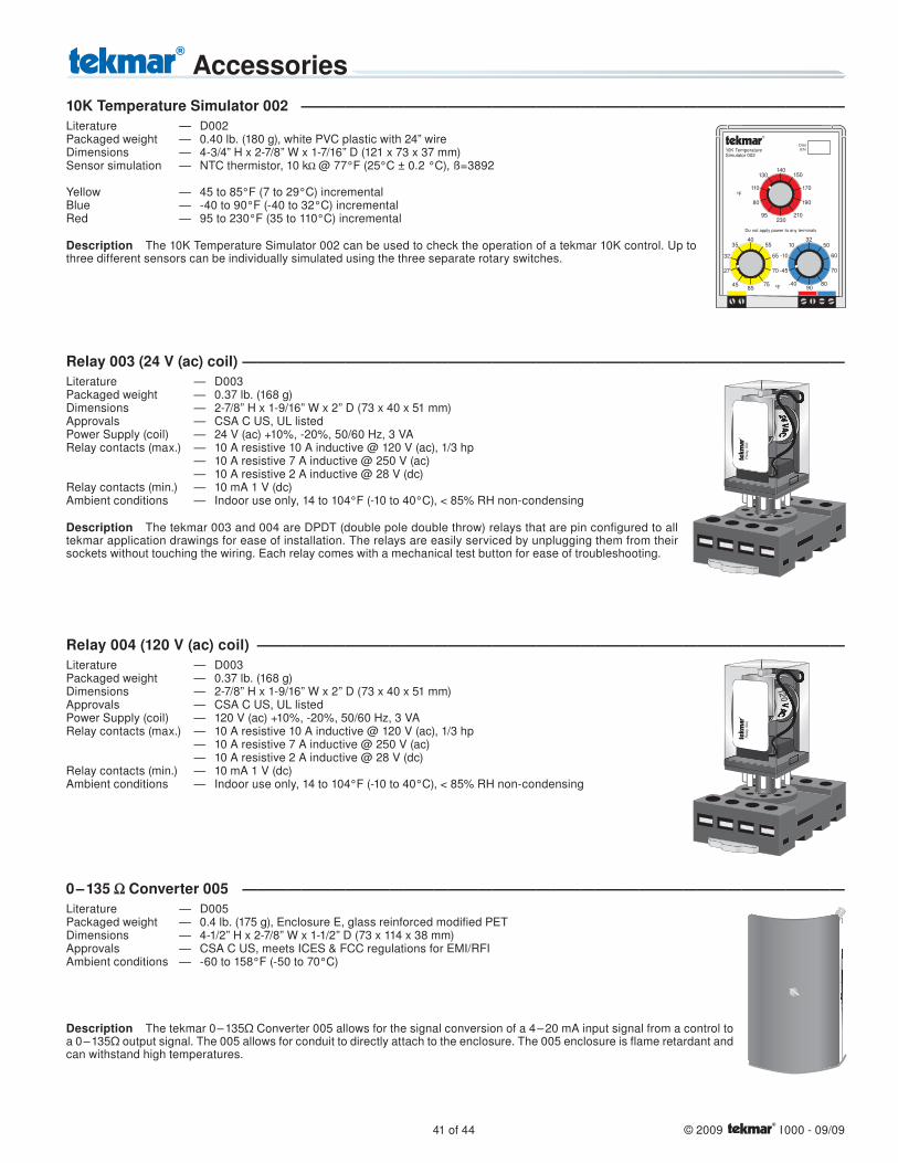
41 of 44 © 2009 I 000 - 09/09
Relay 003 (24 V (ac) coil) ―――――――――――――――――――――――――――――――――――――――――Literature — D003Packaged weight — 0.37 lb. (168 g)Dimensions — 2-7/8” H x 1-9/16” W x 2” D (73 x 40 x 51 mm)Approvals — CSA C US, UL listedPower Supply (coil) — 24 V (ac) +10%, -20%, 50/60 Hz, 3 VARelay contacts (max.) — 10 A resistive 10 A inductive @ 120 V (ac), 1/3 hp — 10 A resistive 7 A inductive @ 250 V (ac) — 10 A resistive 2 A inductive @ 28 V (dc)Relay contacts (min.) — 10 mA 1 V (dc)Ambient conditions — Indoor use only, 14 to 104°F (-10 to 40°C), < 85% RH non-condensing
Description The tekmar 003 and 004 are DPDT (double pole double throw) relays that are pin configured to all tekmar application drawings for ease of installation. The relays are easily serviced by unplugging them from their sockets without touching the wiring. Each relay comes with a mechanical test button for ease of troubleshooting.
10K Temperature Simulator 002 ―――――――――――――――――――――――――――――――――――――Literature — D002Packaged weight — 0.40 lb. (180 g), white PVC plastic with 24” wireDimensions — 4-3/4” H x 2-7/8” W x 1-7/16” D (121 x 73 x 37 mm)Sensor simulation — NTC thermistor, 10 k @ 77°F (25°C ± 0.2 °C), ß=3892
Yellow — 45 to 85°F (7 to 29°C) incrementalBlue — -40 to 90°F (-40 to 32°C) incrementalRed — 95 to 230°F (35 to 110°C) incremental
Description The 10K Temperature Simulator 002 can be used to check the operation of a tekmar 10K control. Up to three different sensors can be individually simulated using the three separate rotary switches.
10K TemperatureSimulator 002
DateS/N
140
230
150
95
80
170
190
110
210
130
32
90
50
-40
-45
60
70
-10
80
10
Do not apply power to any terminals
40
85
55
45
27
65
70
32
75
35
0 – 135 Converter 005 ―――――――――――――――――――――――――――――――――――――――――Literature — D005Packaged weight — 0.4 lb. (175 g), Enclosure E, glass reinforced modifi ed PETDimensions — 4-1/2” H x 2-7/8” W x 1-1/2” D (73 x 114 x 38 mm)Approvals — CSA C US, meets ICES & FCC regulations for EMI/RFIAmbient conditions — -60 to 158°F (-50 to 70°C)
Description The tekmar 0 – 135Ω Converter 005 allows for the signal conversion of a 4 – 20 mA input signal from a control to a 0 – 135Ω output signal. The 005 allows for conduit to directly attach to the enclosure. The 005 enclosure is flame retardant and can withstand high temperatures.
Relay 004 (120 V (ac) coil) ――――――――――――――――――――――――――――――――――――――――Literature — D003Packaged weight — 0.37 lb. (168 g)Dimensions — 2-7/8” H x 1-9/16” W x 2” D (73 x 40 x 51 mm)Approvals — CSA C US, UL listedPower Supply (coil) — 120 V (ac) +10%, -20%, 50/60 Hz, 3 VARelay contacts (max.) — 10 A resistive 10 A inductive @ 120 V (ac), 1/3 hp — 10 A resistive 7 A inductive @ 250 V (ac) — 10 A resistive 2 A inductive @ 28 V (dc)Relay contacts (min.) — 10 mA 1 V (dc)Ambient conditions — Indoor use only, 14 to 104°F (-10 to 40°C), < 85% RH non-condensing
Accessories

© 2009 I 000 - 09/09 42 of 44
Remote Display Module (RDM) 040 ――――――――――――――――――――――――――――――――――――Literature — D040Packaged weight — 0.28 lb. (127 g), Enclosure J, white PVC plastic Dimensions — 2-7/8” H x 2-7/8” W x 13/16” D (73 x 73 x 21 mm)Approvals — CSA C US, meets ICES & FCC regulations for EMI/RFIAmbient conditions — Indoor use only, 32 to 122°F (0 to 50°C), < 90% RH non-condensingPower supply — tekmar controls: 362, 363, 664, 665, 667Relay — 24 V (ac or dc) 0.5 A, pilot duty 6 VA
Description The Remote Display Module (RDM) provides the user with a remote interface to any tekmar control that is first generation tN2 capable. The 040 can be used to view and/or adjust the settings on the control that it is connected to or any (tN1) Room Temperature Unit (RTU) that may be connected to the control. The 040 includes an alert contact that closes when an error is present on a tN2 network.
Room Temperature Unit (RTU) 063 ――――――――――――――――――――――――――――――――――――Literature — D062Packaged weight — 0.22 lb. (100 g), Enclosure J, white PVC plastic Dimensions — 2-7/8” H x 2-7/8” W x 13/16” D (73 x 73 x 21 mm)Approvals — CSA C US, meets ICES & FCC regulations for EMI/RFI Ambient conditions — Indoor use only, 32 to 122°F (0 to 50°C), < 90% RH non-condensingPower supply — tekmar controls: 362, 363, 664, 665, 667Internal Sensor — NTC thermistor, 10 kΩ @ 77°F (25°C ±0.2°C), ß=3892Remote Sensors — tekmar type #: 071, 072, 073, 076, 077, 078, 079. (063 only)Setpoint range — 35 to 100°F (2 to 38°C)
Description The Room Temperature Unit 063 connect to tN1 capable controls, providing temperature display and adjustment access.
Adaptor Plate 007 Literature — D074Packaged weight — 0.13 lb. (60 g), white PVC plasticDimensions — 4-1/2” H x 2-7/8” W x 3/16” D (115 x 73 x 4.8 mm)Ambient conditions — Indoor use only, -20 to 120°F (-30 to 50°C)
Included — two #6 x 5/16” self-tapping screws — two #6-32 x 1/2” white cover plate screws
Description The Adaptor Plate 007 allows for installation of small enclosure G or J type devices onto a 2” x 4” electrical box. The adaptor plate can be mounted vertically or horizontally and is designed to allow wiring to feed through in any position. Included with the adaptor plate are surface painted screws for mounting to the electrical box, and screws to mount the device being used to the plate.
RDM’s & RTU’sThe 040, 062 and 063 are compatible with first generation tN2 products (362, 363, 664, 665, 667)They are not compatible with tN2 models released after 2008 (313, 314, 400, 401, 402, 527, 528, 530)
Remote Start/Stop Module 039 - see page 32.
Transformer 009 / 009K ―――――――――――――――――――――――――――――――――――――――――Literature — D009 Approvals — CSA standard C22.2 #66 part B & UL 5085Ambient conditions — Indoor use only, 32 to 221°F (0 to 105°C)Input power supply — 120 V (ac) ± 10% 60 HzOutput power available — 24 V (ac) ± 10% 60 Hz, 1.67A, 40 VA, Class 2Supplied fuse rating — 250 V (ac), 2.0A
Control Description The tekmar Transformer 009 is a 40 VA, 24 V (ac) transformer for use with products that require an external transformer. The Transformer Kit 009K includes a 4” x 4” electrical J-Box.

Literature... ‘the Complete Reference’tekmar provides one of the most comprehensive literature support programs in the industry. tekmar controls are delivered with all brochures necessary for understanding the control’s operation and efficient installation.
For more informationDownloadable brochures
are available at:www.tekmarcontrols.com
OR Fill out the request card and fax to:(250) 545-0650
OR
Fill out the request card and mail to:
tekmar Control Systems Ltd., Canadatekmar Control Systems, Inc., U.S.A.Head Office: 5100 Silver Star RoadVernon, B.C. Canada V1B 3K4(250) 545-7749 Fax. (250) 545-0650
Request Card❒ Contractor
❒ Wholesaler
❒ Engineer
❒ _______________
❒ Please have the Representative contact me
SetpointControls
Boiler / DHWControls
HeatingControls
Snow MeltingControls
Thermostats
ControlSchools
Name __________________________________________________________
Company _______________________________________________________
Street __________________________________________________________
City ________________________ State _______ Zip ___________________
Phone ______________________ Fax _______________________________
Please send me free tekmar Literature for:
v0050 / I000
tekmarNet®4
© 2009 I 000
Promotional BrochuresGeneral productline information
Information BrochuresChoose controls tomatch applications
Application BrochuresDesign mechanical
applications
Wiring BrochuresWiring &
installation
Data BrochuresControl settings &
sequence of operation
Job RecordRecord settings &
wiring details
User BrochuresUser level
control settings
EssaysIn-depth system data

tekmar Control Systems Ltd., Canadatekmar Control Systems, Inc., U.S.A.Head Office: 5100 Silver Star RoadVernon, B.C. Canada V1B 3K4(250) 545-7749 Fax. (250) 545-0650Web Site: www.tekmarcontrols.com
Product design, software and literature are Copyright © 2009 by:tekmar Control Systems Ltd. and tekmar Control Systems, Inc.
All specifications are subject to change without notice.Printed in Canada. I 000