Embed Size (px)
Citation preview

School of Electrical Engineering and Computer Science Kyungpook National Univ.
Tone-Mapping Functions andMultiple-Exposure Techniquesfor High Dynamic-Range Image
IEEE Transactions on Consumer Electronics,Vol. 54, No. 2, 2008
S. Cvetković, Member, IEEE, J. Klijn, P.H.N. de With, Fellow, IEEE
Presented by Jung Yul Choi

Abstract
Good tonal rendition of video– Importance to ensuring high visual comfort for user– High dynamic range (HDR) scenes
• Requirement of adaptive gradation correction– Tone-mapping function
Purpose– Construction and control of improved tone-
mapping functions• Visibility enhancement of image details in dark regions
– Improvement of SNR• Using multiple-exposure technique
2 / 27

Introduction
Limit of dynamic range– Image signal generated by image sensor
• Noise level• Saturation voltage of sensor
– 74dB dynamic range of CCD-sensor• Sufficiency for most applications
– Requirement of larger dynamic range in order to obtain images with satisfactory quality
• Very large contrast ratio such as outdoor scenes with bright sunlight
3 / 27

Reducing noise level– Double-exposure system
• Acquisition of two image– Capturing with short time interval– Taking with short and long exposure time
• Combination of two images– Good SNR in dark parts of image– Almost no saturation in bright parts of image– Creating output image having improved SNR
4 / 27

Gamma correction– Performing in digital camera system
Fig. 1. Various gamma functions, expanding the darker regions, however, at the expense of reduced amplitude range for the largest part of the input range (upper light gray area).
5 / 27
Improving HDR imaging for moving video signals– Proposing new segmented luminance tone-
mapping function based on splines• Clarification of technique applicability
– Increasing with new multiple-exposure-time sensors» Improving SNR in dark area
6 / 27

An improved tone-mapping method
Knee tone-mapping function– Splitting extended-range gamma transfer function
• Knee and regular gamma function
– Knee transfer function• Stretching black interval to enhance visibility in dark part• Optimal amount of stretching
– Scene, light and sensor dependent
7 / 27

– Start of tone mapping• Splitting luminance input range into n sections
– Use of spline function in each section
– Design of flexible circuit using quadratic splines• Basic spline function
21
22
3
( 1) 1 0,( ) (1 2 ( 1)) 0 1,
( 2) 1 2.
c y for yf y c y y for y
c y for y
+ − < ≤= − − < ≤ − < ≤
(1)
Fig. 2. Two shifted versions of the basic spline function in the middle. 8 / 27

– Calculation of overall function for one section with boundaries 0 < y ≤ 1
– c2 parameter of previous section• Using as c1 parameter of current section
21 2 2 1 1 2 3( ) ( ) 2( ) ( 2 )f y c c c c y c c c y= + + − + − +
2 21 2 3( ) ( 1) (1 2 ( 1))f y c y c y y c y= − + − − +
(2)
9 / 27

– Relationship between n section parameters c1,c2,…,cn• Relating all section parameters ci to one control parameter gk
( ) ( , | 1... )( , | ( ), 1... )
knee knee i
knee k i i k
f y f y c i nf y g c h g i n
= == = = (3)
Fig. 3. (left): Tone-mapping functions: a) Gamma; b) Knee; c) Gamma and Knee together; d) smart extended range Gamma; e) linear transfer function. Figure 3 (right): Example set of knee transfer functions for several values of gk, ranging from 0 to 1.
10 / 27

Control algorithm to determine the optimal knee tone-mapping function– Preferred control strategy
• Relating image median value to mean video level– Achieving by controlling parameter gk of fknee function
Fig. 4. Dynamic control of knee function to optimize the displayed image.
11 / 27

– Realization of such a control• Modifying gk to achieving Med=a*Avg, with a<1
– Determination of coefficient a» Input image and user preferences
– Introduction of new parameter gg
• Controlling extent of gamma function• Depending on user setting and system itself
wherey and fgamma(y) are input and output signals,off is offset, andC represents normalization constant.
( ) ( ) gggammaf y C y off= ⋅ +
[0.2,...,1.0],gg ∈
(4)
12 / 27

– Calculating Med value from image histogram• Considering pixels of detailed regions in image• Occurrence of expansion of dynamic range
– Only visually interesting details in darker image parts
– Guideline of measurement• Where the majority of pixels are• How many low-brightness pixels are left after fknee(y)• How many high-brightness pixels are compressed
13 / 27

Multiple-exposure technique
Improvement of SNR performance– Acquisition of Image
• Taking with at least two exposure time setting– Long and short exposure time
– Simplest way to derive combination of two image• Bringing to same base by weighing images
– Retaining luminance relations occurring in real scene
14 / 27

– Long exposure equals four times short exposure
Fig. 5. Example of dual exposure action where long exposure equals 4 times short exposure.
Luminance range
15 / 27
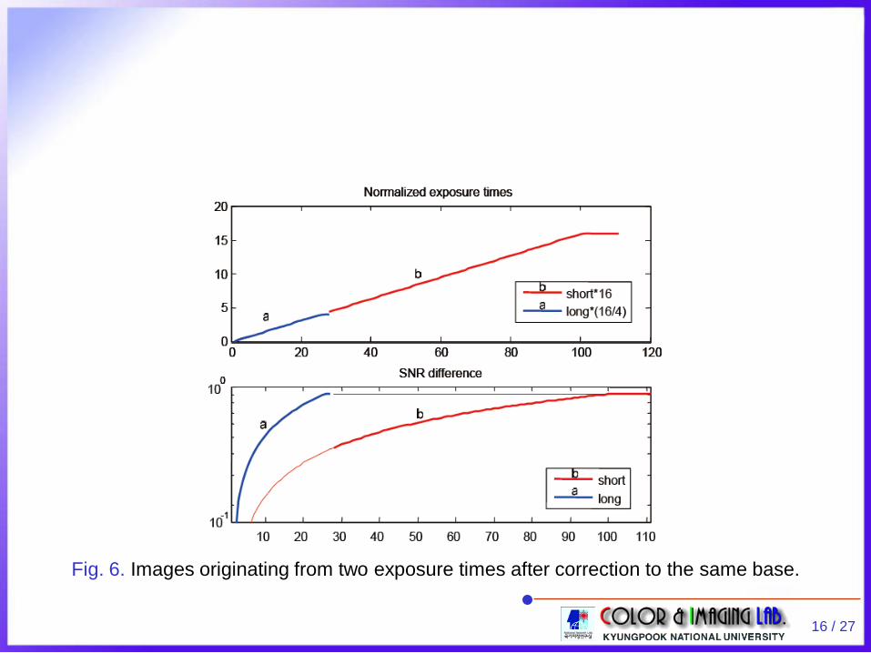
Fig. 6. Images originating from two exposure times after correction to the same base.
16 / 27

– Additional Important consideration • Detailed combining into one image
Fig. 7. Merging long- and short- exposure images into one image: left) soft switching (mixing); right) hard switching.
in max1 2
2 4Yth thth +
= =
17 / 27

Combining long and short exposed images– Relation between light level and output signal
Fig. 8. Basic principle of combining long and short exposed images.
After combining
18 / 27

– Combination of two images • Relation between L (signal of long exposure) and S
where T is threshold,Out represents combined output signal,Ldiv = L/R with R=TL/TS ,TL is long exposure time, andTS is short exposure time.
if ( )else ,
divS T Out LOut S
< == (5)
19 / 27

– Non-linearity of CCD output• Non-continuous of transfer at threshold T when using
exactly R to calculate Ldiv
– Reason of creating color errors
Fig. 9. Matching problems at the cross-over point.20 / 27

Sensor non-linearity correction– Minimum automatic gain control (AGC) setting
• Finding linear region of opto-electronic conversion function (OECF) of sensor response
• Disadvantage– Severely reducing applicable dynamic range of sensor
– Making gradual transition instead of switching• Serious drawbacks
– Increasing noise in S– Need of large mixing range to really annihilate distortion
21 / 27

– Proposal of novel correction function• Appling to Ldiv prior to switching
– Exactly compensating non-linear CCD output and matching transfer of S
• For example
where u is unit-step function, andk1, k2, and p are correction function factors.
– Computation of factors» Measurement of signals S and Ldiv (or L)
2 21 2 ( )( )y x k x k u x p x p= + ⋅ + ⋅ − − (6)
22 / 27

– Non-linearity correction workflow
Fig. 10. Correction of the non-linearity of OECF and image combination.
23 / 27

Experimental results
Testing HDR expansion scheme– Comparing it to other approaches
Fig. 11. Results: (a) standard camera image, (b) smart extended range Gamma, (c) method from the [4], (d) our method (a=0.5).
24 / 27
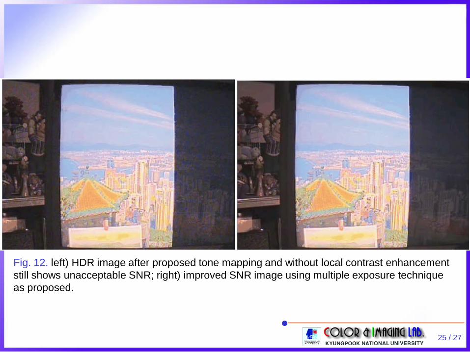
Fig. 12. left) HDR image after proposed tone mapping and without local contrast enhancement still shows unacceptable SNR; right) improved SNR image using multiple exposure technique as proposed.
25 / 27

Fig. 13. From top to bottom: a) Original HDR image; b) HDR image after proposed tone mapping and Local contrast enhancement shows unacceptable SNR; c) Improved SNR image using multiple exposure technique as proposed.
26 / 27

Conclusion
New technique for expansion of HDR images– Using spline functions with one parameter– Control algorithm for spline function– Combination with multiple-exposure time technique
• Improvement of SNR needed for dark areas
Complete presented solution– Attraction both consumer cameras (camcorders,
etc.) and professional equipment
27 / 27