Embed Size (px)
Citation preview
Part No. 84383
200pH/CR pH, ORP,
Conductivity & Resistivity Instrument
Instruction Manual
SAFETY INFORMATION
INSTALLATION: This instrument must be installed by trained instrumentation personnel in accordance with relevant local codes and instructions in this manual. Observe all instrument specifications and ratings.
SHOCK HAZARD: Make sure power to all wires is turned off before proceeding with installation or service of this instrument. High voltage may be present on the input power and relay wiring.
RELAY CONTROL ACTION: 200pH/CR relays will always de-energize on loss of power, equivalent to normal state, regardless of relay state setting for powered operation. Configure any control system using these relays with fail-safe logic accordingly.
PROCESS UPSETS: Because process and safety conditions may depend on consistent operation of this instrument, provide appropriate means to maintain operation during sensor cleaning, replacement or sensor or instrument calibration.
This manual includes specific safety information with the following designations and formats:
WARNING: OF POTENTIAL FOR PERSONAL INJURY.
CAUTION: of possible instrument damage or malfunction.
NOTE: of important operating information.

TABLE OF CONTENTS
CHAPTER 1: GETTING STARTED .............................................................1 Introduction............................................................................................................................... 1 Features ................................................................................................................................... 1 Overview of Operation............................................................................................................ 2 Installation & Setup Procedure .............................................................................................. 2
CHAPTER 2: INSTALLING THE 200PH/CR ...............................................3 Unpacking ................................................................................................................................ 3 Installation................................................................................................................................. 3 Electrical Connections............................................................................................................ 3
CHAPTER 3: USING THE 200PH/CR ..........................................................7 Applying Power to the 200pH/CR......................................................................................... 7 The Display.............................................................................................................................. 7 The Keypad.............................................................................................................................. 8 Using the Menus...................................................................................................................... 9 Installing a Sensor .................................................................................................................10 Measurement Designations.................................................................................................10 Displaying Measurements....................................................................................................10 Alarm Indications...................................................................................................................12
CHAPTER 4: MAKING MEASUREMENTS.............................................. 13 Measurement Process .........................................................................................................13 Measurement Types .............................................................................................................13 Selecting a Measurement Type...........................................................................................15 Cell Constants .......................................................................................................................15 Conductivity Temperature Compensation..........................................................................16 pH/ORP Temperature Compensation................................................................................17 AC Power Frequency ...........................................................................................................18
CHAPTER 5: USING SETPOINTS............................................................ 19 Overview.................................................................................................................................19 Setpoint Signal......................................................................................................................19 Setpoint Value .......................................................................................................................19 Setpoint State ........................................................................................................................19 Assigned Relay .....................................................................................................................19 Programming a Setpoint ......................................................................................................20 USP Setpoint.........................................................................................................................21
CHAPTER 6: USING RELAYS................................................................... 22 Description.............................................................................................................................22 Electrical Connections..........................................................................................................22 Delay Time.............................................................................................................................22 Hysteresis ..............................................................................................................................22 Relay State.............................................................................................................................22 Programming a Relay...........................................................................................................22
CHAPTER 7: USING ANALOG OUTPUTS............................................... 24 Description.............................................................................................................................24 Electrical Connections..........................................................................................................24 Programming the Analog Outputs .......................................................................................24 Analog Output Calibration....................................................................................................25
CHAPTER 8: METER CALIBRATION ...................................................... 27 Overview.................................................................................................................................27 Calibration Verification.........................................................................................................27 Calibration Procedure ..........................................................................................................28
CHAPTER 9: SENSOR CALIBRATION.................................................... 31 Conductivity/Resistivity Cell Constants...............................................................................31 Conductivity/Resistivity Sensor Calibration........................................................................31 pH/ORP Sensor Calibration.................................................................................................33 pH Sensor Diagnostics ........................................................................................................35
CHAPTER 10: SECURITY/LOCKOUT ..................................................... 36 Security Features..................................................................................................................36 Changing the Password.......................................................................................................36 Enabling the Lockout ............................................................................................................36 Accessing a Locked Menu...................................................................................................37
CHAPTER 11: OTHER FUNCTIONS ........................................................ 38 Averaging...............................................................................................................................38 System Reset ........................................................................................................................38 Setting the Temperature Source .........................................................................................39 Sending Data to a Printer or Computer..............................................................................39
CHAPTER 12: TROUBLESHOOTING ...................................................... 41 Off-Line Self-Diagnostics .....................................................................................................41 On-Line Diagnostics ............................................................................................................41 Troubleshooting.....................................................................................................................42 Recovery Procedure.............................................................................................................42
CHAPTER 13: SERVICE ............................................................................ 43 Fuse Replacement................................................................................................................43 Reducing 200pH/CR Patch Cord Length ...........................................................................43 Recommended Spare Parts List.........................................................................................44 Accessories...........................................................................................................................44
CHAPTER 14: TECHNICAL ILLUSTRATIONS ....................................... 45 Menu Trees............................................................................................................................46 Overall Dimensions...............................................................................................................49 Panel Cutout ..........................................................................................................................50 Exploded Assembly ..............................................................................................................50 Pipe Mounting........................................................................................................................51 Sealed Rear Assembly.........................................................................................................51 Printed Circuit Board Layout................................................................................................52 Rear Panel Wiring and Patch Cords...................................................................................53 Calibrators .............................................................................................................................54 Meter Calibration Connections............................................................................................54
SPECIFICATIONS ....................................................................................... 55
WARRANTY.................................................................................................. 57

Chapter 1 Getting Started 1
CHAPTER 1: GETTING STARTED
INTRODUCTION
The 200pH/CR is an analytical and process control instrument for measuring solution properties. It can process two signals from each of two sensors for pH, ORP, two- and four-electrode conductivity or resistivity in most combinations. A 16-character liquid crystal display conveys measuring data and setup information. The display is backlit for viewing in all lighting conditions. The menu structure allows the operator to modify all operational parameters by using keys on the front panel. A menu-lockout feature, with password protection, is available to prevent the unauthorized use of the meter. The 200pH/CR can have up to four relays for process control.
NOTE: The 200pH/CR design allows two channels of pH, ORP and/or conductivity measurement in most applications identified in the compatibility table below. Two incompatible sensors may be used only if plastic tanks, piping, etc. isolate them electrically from each other. Where an incompatible sensor pair is required in the same process, use two separate instruments.
For pH and ORP, large differences in potential between two sensor locations may cause interference. Factors that could increase solution potential differences are long distances between sensors in a plastic piped systems or electrical currents running through piping as in electroplating, electro-deionization, etc. Where these or similar conditions exist, test the application and use two separate 200pH/CR instruments if needed.
The 200pH/CR instrument is equipped with a communication interface that can be configured as either an RS422 or an RS232. This interface provides real-time data output and complete instrument configuration capabilities for central monitoring via personal computer or Programmable Logic Controller (PLC). An external isolator for the digital communications signal is required if measurements other than conductivity with 0.1/cm cell constants are being made. For coverage of communications, see Manual 84364.
FEATURES
Display: 1 line x 16 character backlit LCD.
Measurements: pH, ORP, resistivity, conductivity, °C, °F, total dissolved solids, %rejection, difference, ratio, %HCl, %NaOH, %H2SO4.
Measurement Channels: 2.
Signal Inputs per channel: 2 (total of 4 signals for measurement).
Measurement Cycle Time: 1 second (4 measurements processed per second).
Programmable: all setup information is stored in a non-volatile memory.
Setpoints (alarms): 4 independent alarms programmable as high, low or USP limits.
Relays: up to 4 with programmable delay time and hysteresis.
Outputs: 2 analog outputs (0/4-20mA).
Communications: RS232/RS422 interface, bi-directional; external isolator recommended with measurements other than conductivity with 0.1/cm cell constants.
Security: keypad lockout with password.
Calibration: complete instrument, output, and sensor calibration. Calibration can be NIST traceable.
Watchdog Timer: with a power supply monitor, to prevent unexpected instrument lockup.
Built-In Diagnostics: several self tests can be initiated at any time.
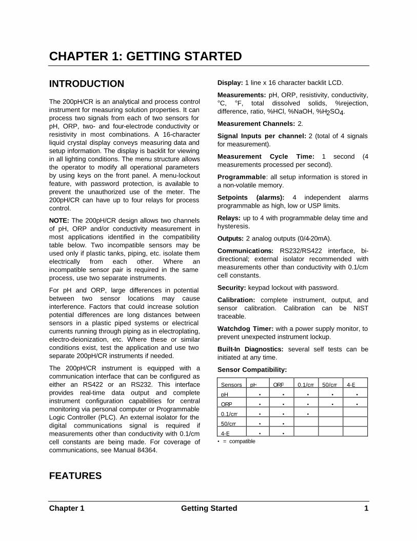
Sensor Compatibility:
Sensors pH ORP 0.1/cm 50/cm 4-E
pH • • • • •
ORP • • • • •
0.1/cm • • •
50/cm • •
4-E • • • = compatible
2 Getting Started Chapter 1
OVERVIEW OF OPERATION
When power is applied to the 200pH/CR, the initialization process begins. The instrument will perform a number of self tests. Any problems detected during these tests will be reported by a displayed message.
Next, all setup parameters (setpoints, states, relay conditions, etc.) are restored from a non-volatile memory.
The meter will then begin the measurement process. A complete measurement cycle is performed once per second and consists of the following:
1. Measure four signals and compute four measurements.
2. Check setpoints against the measurements.
3. Control the relays.
4. Update analog output signals.
5. Transmit measurement data over the communication port.
6. Display data (if not displaying a menu).
At any time during this process the menus can be accessed by pressing one of the menu keys. The display of a menu will not affect the measurement process.
INSTALLATION & SETUP PROCEDURE
The following guideline shows the steps necessary to install a 200pH/CR meter and begin operation.
1. Follow the meter installation procedure for physically mounting the meter, as outlined in Chapter 2. The meter may be mounted in a panel, on a pipe, or on a wall.
Optional: the rear cover is required for wall and pipe mounting. Drill holes as needed for conduit or cable grips, install the cover and wire the meter before wall or pipe mounting.
2. Make all necessary electrical connections to the meter after panel mounting. The wiring procedure is outlined in Chapter 2.
3. Required wiring: input power and sensor cables.
4. Optional wiring: relays, analog outputs, and serial port.
5. Set appropriate input line frequency to reduce measurement noise. See AC POWER FREQUENCY in Chapter 4.
6. Instrument calibration is performed at the factory to specifications. Re-calibration is not necessary. If QA/QC practice requires it, meter calibration may be verified as outlined in Chapter 8.
7. Connect sensors to the patch cords.
CAUTION: Be certain that patch cord is wired specifically for the type of sensor to be connected or damage could result.
8. Select the desired measurements for each sensor as shown in SELECTING A MEASUREMENT TYPE in Chapter 4.
9. Enter sensor constants from the label of each cell as outlined in ENTERING/EDITING CELL CONSTANTS in Chapter 9. DO NOT PERFORM A SENSOR CALIBRATION except for pH.
10. Optional: program the analog outputs as shown in Chapter 7. DO NOT PERFORM AN OUTPUT CALIBRATION.
11. Optional: program the setpoints as shown in Chapter 5.
12. Optional: program the relays as shown in Chapter 6.
13. Optional: program other features such as averaging method, special temperature compensation, security/password, etc, as needed.
Chapter 2 Installation 3
CHAPTER 2: INSTALLING THE 200pH/CR
UNPACKING
Each 200pH/CR is packed in an individual biodegradable carton. Retain the packaging in the event that the instrument must be returned to Thornton for service or calibration.
This carton should contain:
1 - 200pH/CR Instrument
1 - Set of panel mounting hardware with gasket
1 - 84383 Instruction Manual
1 - 84384 Startup Instruction Sheet
1 - Certificate of Calibration
INSTALLATION
The 200pH/CR can be mounted in a panel, on a pipe or attached to a wall.
Panel Mounting Cutout and Installation
The panel cutout should measure 7.56 inches wide by 3.780 inches high (192 mm X 96 mm). Drill four holes for the #10 mounting screws. See Figure 14.3 for panel cutout size and mounting screw hole spacing. When mounting multiple instruments on the same panel, note the front flange dimensions in Figure 14.2 in order to allow enough space between instruments.
Panel cutouts should be clean and free of burrs and sharp edges. The proper dimensions allow an instrument to slide freely into the cutout.
Install the panel gasket (supplied with instrument) on the instrument mounting flange. Slide the instrument into the cutout and secure it with the mounting screws.
CAUTION: Do not over tighten the screws as this may crack the case.
If the rear cover is used in a panel mounted installation, the 200pH/CR unit must be installed in the panel opening before the rear cover is installed.
Wall Mounting
The 200pH/CR can be easily mounted to a wall when the rear cover is installed. The flanges on the ends of the cover contain holes for screws to fasten the assembly to the wall. A layout for drilling mounting holes is included in the wall mount kit.
Pipe Mounting
The 200pH/CR can be mounted to a pipe with the pipe mounting accessory kit. The assembly is shown in Figure 14.5.
ELECTRICAL CONNECTIONS
All electrical connections are made at pluggable terminal blocks at the rear of the 200pH/CR case.
WARNING: MAKE SURE POWER TO ALL WIRES IS TURNED OFF BEFORE PRO-CEEDING WITH THE INSTALLATION. HIGH VOLTAGE MAY BE PRESENT ON THE INPUT POWER WIRES AND RELAY WIRES.
CAUTION: A good power earth ground connection is required for safety and for proper operation of the instrument. To prevent electrostatic discharge (ESD) from damaging the instrument during installation, the installer must also be electrically grounded i.e., wear a conductive wrist strap connected to earth ground.
Do not run power and relay wiring in the same conduit or parallel with sensor and output signal wiring to prevent interference.
Input Power and Relay Connections
Terminal block TB1 contains connections for the input line power and relay contacts. Depending upon the model number, the 200pH/CR will have either 2 or 4 relays. Table 2.1 shows the wiring sequence.
All relays have “dry contacts”; they are potential-free and require external power to be wired in series with the load and instrument terminals.
4 Installation Chapter 2
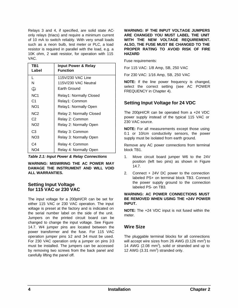
Relays 3 and 4, if specified, are solid state AC-only relays (triacs) and require a minimum current of 10 mA to switch reliably. With very small loads such as a neon bulb, test meter or PLC, a load resistor is required in parallel with the load, e.g. a 10K ohm, 2 watt resistor, for operation with 115 VAC.
TB1 Label
Input Power & Relay Function
L 115V/230 VAC Line N 115V/230 VAC Neutral
Earth Ground NC1 Relay1: Normally Closed C1 Relay1: Common NO1 Relay1: Normally Open NC2 Relay 2: Normally Closed C2 Relay 2: Common NO2 Relay 2: Normally Open C3 Relay 3: Common NO3 Relay 3: Normally Open C4 Relay 4: Common NO4 Relay 4: Normally Open
Table 2.1: Input Power & Relay Connections
WARNING: MISWIRING THE AC POWER MAY DAMAGE THE INSTRUMENT AND WILL VOID ALL WARRANTIES.
Setting Input Voltage for 115 VAC or 230 VAC
The input voltage for a 200pH/CR can be set for either 115 VAC or 230 VAC operation. The input voltage is preset at the factory and is indicated on the serial number label on the side of the unit. Jumpers on the printed circuit board can be changed to change the input voltage. See Figure 14.7. W4 jumper pins are located between the power transformer and the fuse. For 115 VAC operation jumper pins 1-2 and 3-4 must be used. For 230 VAC operation only a jumper on pins 2-3 must be installed. The jumpers can be accessed by removing two screws from the back panel and carefully lifting the panel off.
WARNING: IF THE INPUT VOLTAGE JUMPERS ARE CHANGED YOU MUST LABEL THE UNIT WITH THE NEW VOLTAGE REQUIREMENT. ALSO, THE FUSE MUST BE CHANGED TO THE PROPER RATING TO AVOID RISK OF FIRE HAZARD
Fuse requirements:
For 115 VAC: 1/8 Amp, SB, 250 VAC
For 230 VAC: 1/16 Amp, SB, 250 VAC
NOTE: If the line power frequency is changed, select the correct setting (see AC POWER FREQUENCY in Chapter 4).
Setting Input Voltage for 24 VDC
The 200pH/CR can be operated from a +24 VDC power supply instead of the typical 115 VAC or 230 VAC source.
NOTE: For all measurements except those using 0.1 or 10/cm conductivity sensors, the power supply must be isolated from earth ground.
Remove any AC power connections from terminal block TB1.
1. Move circuit board jumper W6 to the 24V position (left two pins) as shown in Figure 14.7.
2. Connect + 24V DC power to the connection labeled PS+ on terminal block TB3. Connect the power supply ground to the connection labeled PS- on TB3.
WARNING: AC POWER CONNECTIONS MUST BE REMOVED WHEN USING THE +24V POWER INPUT.
NOTE: The +24 VDC input is not fused within the meter.
Wire Size
The pluggable terminal blocks for all connections will accept wire sizes from 26 AWG (0.126 mm2) to 14 AWG (2.08 mm2), solid or stranded and up to 12 AWG (3.31 mm2) stranded only.
Chapter 2 Installation 5
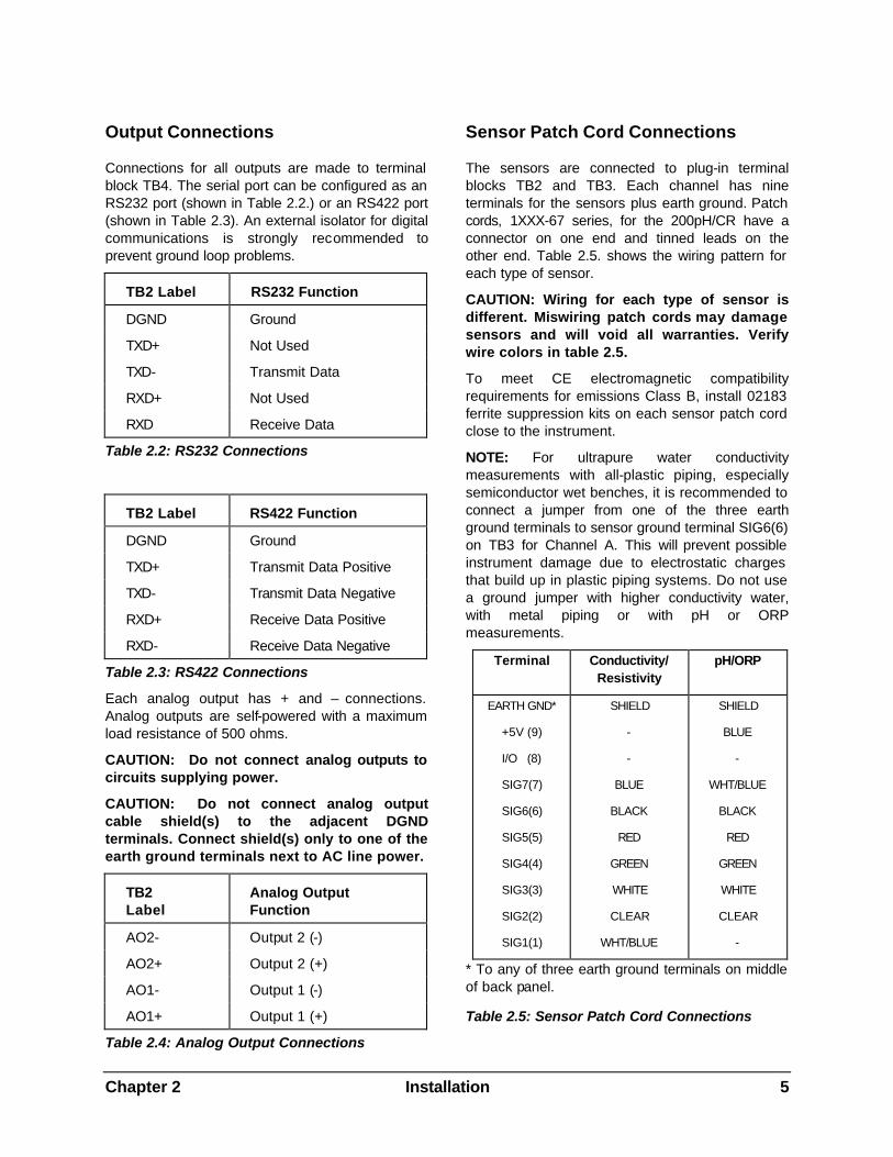
Output Connections
Connections for all outputs are made to terminal block TB4. The serial port can be configured as an RS232 port (shown in Table 2.2.) or an RS422 port (shown in Table 2.3). An external isolator for digital communications is strongly recommended to prevent ground loop problems.
TB2 Label RS232 Function
DGND Ground
TXD+ Not Used
TXD- Transmit Data
RXD+ Not Used
RXD Receive Data
Table 2.2: RS232 Connections
TB2 Label RS422 Function
DGND Ground
TXD+ Transmit Data Positive
TXD- Transmit Data Negative
RXD+ Receive Data Positive
RXD- Receive Data Negative
Table 2.3: RS422 Connections
Each analog output has + and – connections. Analog outputs are self-powered with a maximum load resistance of 500 ohms.
CAUTION: Do not connect analog outputs to circuits supplying power.
CAUTION: Do not connect analog output cable shield(s) to the adjacent DGND terminals. Connect shield(s) only to one of the earth ground terminals next to AC line power.
TB2 Label
Analog Output Function
AO2- Output 2 (-)
AO2+ Output 2 (+)
AO1- Output 1 (-)
AO1+ Output 1 (+)
Table 2.4: Analog Output Connections
Sensor Patch Cord Connections
The sensors are connected to plug-in terminal blocks TB2 and TB3. Each channel has nine terminals for the sensors plus earth ground. Patch cords, 1XXX-67 series, for the 200pH/CR have a connector on one end and tinned leads on the other end. Table 2.5. shows the wiring pattern for each type of sensor.
CAUTION: Wiring for each type of sensor is different. Miswiring patch cords may damage sensors and will void all warranties. Verify wire colors in table 2.5.
To meet CE electromagnetic compatibility requirements for emissions Class B, install 02183 ferrite suppression kits on each sensor patch cord close to the instrument.
NOTE: For ultrapure water conductivity measurements with all-plastic piping, especially semiconductor wet benches, it is recommended to connect a jumper from one of the three earth ground terminals to sensor ground terminal SIG6(6) on TB3 for Channel A. This will prevent possible instrument damage due to electrostatic charges that build up in plastic piping systems. Do not use a ground jumper with higher conductivity water, with metal piping or with pH or ORP measurements.
Terminal Conductivity/ Resistivity
pH/ORP
EARTH GND*
+5V (9)
I/O (8)
SIG7(7)
SIG6(6)
SIG5(5)
SIG4(4)
SIG3(3)
SIG2(2)
SIG1(1)
SHIELD
-
-
BLUE
BLACK
RED
GREEN
WHITE
CLEAR
WHT/BLUE
SHIELD
BLUE
-
WHT/BLUE
BLACK
RED
GREEN
WHITE
CLEAR
-
* To any of three earth ground terminals on middle of back panel.
Table 2.5: Sensor Patch Cord Connections
6 Installation Chapter 2
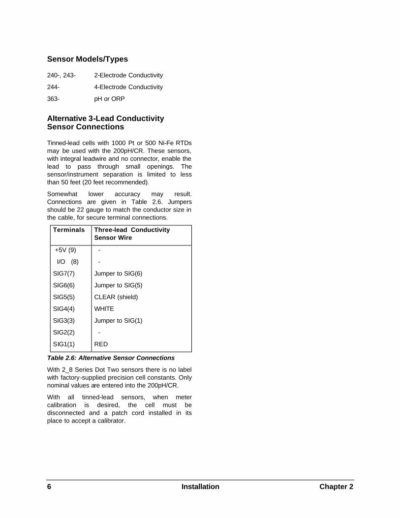
Sensor Models/Types
240-, 243- 2-Electrode Conductivity
244- 4-Electrode Conductivity
363- pH or ORP
Alternative 3-Lead Conductivity Sensor Connections
Tinned-lead cells with 1000 Pt or 500 Ni-Fe RTDs may be used with the 200pH/CR. These sensors, with integral leadwire and no connector, enable the lead to pass through small openings. The sensor/instrument separation is limited to less than 50 feet (20 feet recommended).
Somewhat lower accuracy may result. Connections are given in Table 2.6. Jumpers should be 22 gauge to match the conductor size in the cable, for secure terminal connections.
Terminals Three-lead Conductivity Sensor Wire
+5V (9)
I/O (8)
SIG7(7)
SIG6(6)
SIG5(5)
SIG4(4)
SIG3(3)
SIG2(2)
SIG1(1)
-
-
Jumper to SIG(6)
Jumper to SIG(5)
CLEAR (shield)
WHITE
Jumper to SIG(1)
-
RED
Table 2.6: Alternative Sensor Connections
With 2_8 Series Dot Two sensors there is no label with factory-supplied precision cell constants. Only nominal values are entered into the 200pH/CR.
With all tinned-lead sensors, when meter calibration is desired, the cell must be disconnected and a patch cord installed in its place to accept a calibrator.
Chapter 3 Using the 200pH/CR 7
CHAPTER 3: USING THE 200pH/CR
APPLYING POWER TO THE 200PH/CR
After applying power to the meter, the display will show an introduction message for three seconds and then begin making measurements. This message shows the model number and the software version number as follows:
65XX Ver X.X
While the message is being displayed the instrument is performing self diagnostics. Various circuits are tested during this process and any failure will be noted with a message. The diagnostics can be repeated at any time via the menus.
The default measurement display is the primary readings from the sensors on channel A and B as shown below:
A1.76µS B2.11µS
All 200pH/CR meters are calibrated from the factory and normally require no further calibration. If QA/QC practice requires it, the instrument be calibrated after installation. See Chapter 8 for more information on meter calibration.
THE DISPLAY
The 200pH/CR uses a 1 line by 16 character alphanumeric display to convey all measurement and setup information. This instrument will display one or two measurements, each with channel indication and unit of measure. A typical display of measurement data is:
A7.76pH B2.10µS
This display indicates that channel A is measuring 7.76pH and channel B is measuring 2.10µS/cm. The display of the other measurements can be achieved by pressing the UP or DOWN keys.
In the menus, an underline cursor and flashing (bold) characters will indicate a field that can be changed. A typical menu appears as follows:
SP1=17.00 M High
This menu indicates that setpoint #1 is programmed at a value of 17.00 M (million) and is set as a high limit. The cursor is under the digit “7” indicating that the UP and DOWN keys can be used to change it. The RIGHT and LEFT keys will move the cursor to the next or previous field.
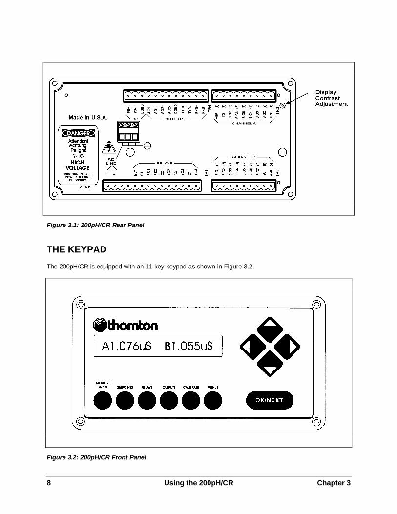
Display Contrast Adjustment
The contrast quality of the display can change with ambient temperature. The display contrast is adjusted from the factory for operation at standard room temperature (25°C). If the meter is operated at an ambient temperature that is much different then it may be necessary to make an adjustment. A potentiometer is accessible from the back side of the instrument to change the contrast. Use a small slotted screwdriver to gently turn the potentiometer. A counter-clockwise turn will increase the contrast and a clock-wise turn will decrease the contrast. The rear panel is shown in Figure 3.1.
8 Using the 200pH/CR Chapter 3
Figure 3.1: 200pH/CR Rear Panel
THE KEYPAD
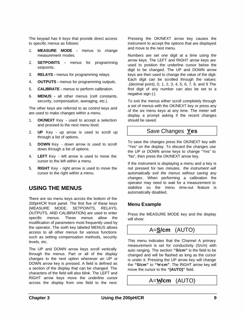
The 200pH/CR is equipped with an 11-key keypad as shown in Figure 3.2.
Figure 3.2: 200pH/CR Front Panel
Chapter 3 Using the 200pH/CR 9
The keypad has 6 keys that provide direct access to specific menus as follows:
1. MEASURE MODE - menus to change measurement modes.
2. SETPOINTS - menus for programming setpoints.
3. RELAYS - menus for programming relays.
4. OUTPUTS - menus for programming outputs.
5. CALIBRATE - menus to perform calibration.
6. MENUS - all other menus (cell constants, security, compensation, averaging, etc.).
The other keys are referred to as control keys and are used to make changes within a menu.
1. OK/NEXT Key - used to accept a selection and proceed to the next menu level.
2. UP Key - up arrow is used to scroll up through a list of options.
3. DOWN Key - down arrow is used to scroll down through a list of options.
4. LEFT Key - left arrow is used to move the cursor to the left within a menu.
5. RIGHT Key - right arrow is used to move the cursor to the right within a menu.
USING THE MENUS
There are six menu keys across the bottom of the 200pH/CR front panel. The first five of these keys (MEASURE MODE, SETPOINTS, RELAYS, OUTPUTS, AND CALIBRATION) are used to enter specific menus. These menus allow the modification of parameters most frequently used by the operator. The sixth key labeled MENUS allows access to all other menus for various functions such as setting compensation methods, security levels, etc.
The UP and DOWN arrow keys scroll vertically through the menus. Part or all of the display changes to the next option whenever an UP or DOWN arrow key is pressed. A field is defined as a section of the display that can be changed. The characters of the field will also blink. The LEFT and RIGHT arrow keys move the underline cursor across the display from one field to the next.
Pressing the OK/NEXT arrow key causes the instrument to accept the options that are displayed and move to the next menu.
Numbers are set one digit at a time using the arrow keys. The LEFT and RIGHT arrow keys are used to position the underline cursor below the digit to be changed. The UP and DOWN arrow keys are then used to change the value of the digit. Each digit can be scrolled through the values: .(decimal point), 0, 1, 2, 3, 4, 5, 6, 7, 8, and 9 The first digit of any number can also be set to a negative sign (-).
To exit the menus either scroll completely through a set of menus with the OK/NEXT key or press any of the six menu keys at any time. The meter will display a prompt asking if the recent changes should be saved.
Save Changes Yes
To save the changes press the OK/NEXT key with “Yes” on the display. To discard the changes use the UP or DOWN arrow keys to change “Yes” to “No”, then press the OK/NEXT arrow key.
If the instrument is displaying a menu and a key is not pressed for two minutes, the instrument will automatically exit the menus without saving any changes. When performing a calibration the operator may need to wait for a measurement to stabilize so the menu time-out feature is automatically disabled.
Menu Example
Press the MEASURE MODE key and the display will show:
A=S/cm (AUTO)
This menu indicates that the Channel A primary measurement is set for conductivity (S/cm) with auto ranging. The section “S/cm” is the field to be changed and will be flashed as long as the cursor is under it. Pressing the UP arrow key will change the “S/cm” to “Ω -cm”. The RIGHT arrow key will move the cursor to the “(AUTO)” field.
A=Ω/cm (AUTO)
10 Using the 200pH/CR Chapter 3
The OK/NEXT key is used to accept the entry and move to the next menu. When the last menu level is reached the following message is displayed:
Save Changes Yes
Pressing the OK/NEXT key will save the changes and exit the menus. The UP and DOWN arrow keys can be used to change the “Yes” to “No”. Pressing the OK/NEXT key with “No” will discard the changes and exit the menus.
INSTALLING A SENSOR
Each probe is equipped with a cell and temperature sensor. Each of these elements have calibration constants (or cell constants) that must be programmed into the meter for proper operation. These factors are printed on the sensor as well as a Certificate of Calibration supplied with each conductivity sensor. The label may look like this:
RES M=1.0034 TEMP M=1.0015
RES M is the conductivity cell constant, and TEMP M is the temperature sensor constant. pH sensors will have pH M (multiplier), pH A (adder) and TEMP M (multiplier) constants. See ENTERING/EDITING CELL CONSTANTS in Chapter 9 for information on entering cell constants.
MEASUREMENT DESIGNATIONS
The 200pH/CR instrument will measure four fundamental signals during each measurement cycle. These measurements are the conductivity or pH and temperature of the probe on channel A and the conductivity or pH and temperature of the probe on channel B.
The 200pH/CR can process and display four calculated measurements. They are referred to as A primary, A secondary, B primary and B secondary. These measurements are designated by a single letter as follows:
A = channel A primary measurement
a = channel A secondary measurement
B = channel B primary measurement
b = channel B secondary measurement
Upper case letters are used to indicate the primary measurements and lower case letters are used to indicate the secondary measurements.
Each of the four calculated measurements can be one of the following:
1. pH
2. ORP
3. Resistivity
4. Conductivity
5. Total Dissolved Solids (TDS)
6. Degrees C
7. Degrees F
8. % Rejection
9. Difference (A-B or B-A)
10. Ratio (A/B or B/A)
11. %HCl
12. %NaOH
13. %H2S04
DISPLAYING MEASUREMENTS
Changing the Display of Measurements
The 200pH/CR display can show either one or two measurements at a time. The display of measurements can be changed by using the UP or DOWN arrow keys. Pressing one of these keys will cause the meter to change the display mode (show an alternative set of data).
The display modes for two measurements per line are:
Mode #1: A primary and B primary (three significant digits displayed for each parameter):
A1.76µS B2.11µS
Mode #2: A secondary and B secondary (three significant digits displayed for each parameter).
Chapter 3 Using the 200pH/CR 11
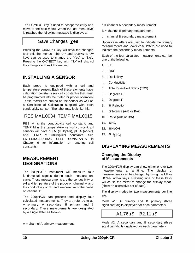
a25.2°C b25.1°C
Mode # 3: A Primary and A Secondary (four significant digits displayed for each parameter):
A1.764µS 25.10°C
Mode #4: B primary and B Secondary (four significant digits displayed for each parameter):
B2.109µS 25.12°C
Note that when two measurements from the same channel are displayed, the secondary measurement indicator ( a or b) is not displayed. This allows for greater precision in the display of the primary measurement.
The default display setting (after a system reset) is mode #1 (A Primary & B Primary).
The display modes for one measurement per line are:
Mode #1: A Primary:
A 1.765µS/cm C
Mode #2: A Secondary:
a 25.25 deg C
Mode #3: B Primary:
B 2.109µS/cm C
Mode # 4: B Secondary:
b 25.12 deg C
Setting the Number of Measurements per Display Line
The 200pH/CR can be set to display either one or two measurements per line.
To change this feature:
Press the MENUS key and the following menu will appear:
Menus use arrows
Press the UP arrow key until “Display Menus” is displayed.
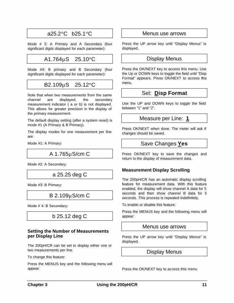
Display Menus
Press the OK/NEXT key to access this menu. Use the Up or DOWN keys to toggle the field until “Disp Format” appears. Press OK/NEXT to access this menu.
Set: Disp Format
Use the UP and DOWN keys to toggle the field between “1” and “2”.
Measure per Line: 1
Press OK/NEXT when done. The meter will ask if changes should be saved.
Save Changes Yes
Press OK/NEXT key to save the changes and return to the display of measurement data.
Measurement Display Scrolling
The 200pH/CR has an automatic display scrolling feature for measurement data. With this feature enabled, the display will show channel A data for 5 seconds and then show channel B data for 5 seconds. This process is repeated indefinitely.
To enable or disable this feature:
Press the MENUS key and the following menu will appear:
Menus use arrows
Press the UP arrow key until “Display Menus” is displayed.
Display Menus
Press the OK/NEXT key to access this menu
12 Using the 200pH/CR Chapter 3
Set: Auto Scroll
Use the Up or Down arrow keys to toggle the field until “Auto Scroll” appears. Press OK/NEXT to access this menu.
Auto Scroll=off
Use the UP or DOWN arrow keys to toggle the field from “Off” to “On”. Press the OK/NEXT key when done. The meter will ask if changes should be saved.
Save Changes Yes
Press the OK/NEXT key to save the changes and return to the display of measurement data.
ALARM INDICATIONS
A setpoint can be programmed as a high limit, a low limit or a USP limit. When a measurement is higher than a high (or USP) point or lower than a low point then the setpoint is in alarm state. This condition is indicated by flashing the corresponding measurement value in the normal operating display. See Chapter 5: Using Setpoints.
Chapter 4 Making Measurements 13
CHAPTER 4: MAKING MEASUREMENTS
MEASUREMENT PROCESS
The 200pH/CR will process two measurements from each of the two channels. The measurements of each channel are referred to as the primary and the secondary measurement. The instrument will process a total of four different measurements per cycle.
Measurements are designated as follows:
A = channel A primary measurement
a = channel A secondary measurement
B = channel B primary measurement
b = channel B secondary measurement
Note that upper case letters are used to indicate the primary measurements and lower case letters are used to indicate the secondary measurements.
MEASUREMENT TYPES
Each of the four measurements (channel A primary, etc.) can be programmed as one of the following:
1. pH
2. ORP
3. Resistivity
4. Conductivity
5. Total Dissolved Solids (TDS)
6. Degrees C
7. Degrees F
8. % Rejection
9. Difference (A-B or B-A)
10. Ratio (A/B or B/A)
11. %HCl - Hydrochloric Acid
12. %NaOH - Sodium Chloride
13. %H2S04 - Sulphuric Acid
pH and ORP
pH is displayed with fixed range. ORP is displayed in fixed range millivolts (mV).
Resistivity
Resistivity is expressed in ohms-centimeter (Ω-cm). This measurement can be displayed with a prefix in front of the units. The prefixes are k (kilo or 1,000) and M (Mega or 1,000,000).
The display can be set for a fixed range such as Ω-cm, KΩ-cm (1,000Ω-cm), and M (Mega or 1,000,000). The 200pH/CR can also be set for auto ranging where the range will be automatically adjusted for the most appropriate display. The range is set via the measure mode menus.
1,000,000 Ω-cm = 1,000KΩ-cm = 1MΩ-cm
Conductivity
Conductivity is expressed in siemens per centimeter (S/cm) and is the reciprocal of resistivity. This measurement can be displayed with a prefix in front of the units. The prefixes are m (milli or 1/1,000) and µ (micro or 1/1,000,000). The 200pH/CR can also be set for auto ranging where the range will be automatically adjusted for the most appropriate display. The range is set via the measure mode menus.
1 S/cm = 1,000 mS/cm = 1,000,000 µS/cm
Total Dissolved Solids
Total Dissolved Solids (TDS) is another way to measure and display conductivity/resistivity data. TDS is the equivalent of Sodium Chloride (NaCl) required to produce the measured conductivity--approximately 0.46 ppm TDS per µS/cm. If some other conversion is desired, it is necessary to adjust the cell constant to give direct readout. For example, if a conversion of 0.6 ppm TDS per µS/cm is desired, the cell multiplier to be entered into the 200pH/CR is 0.6/0.46 x Multiplier on sensor label. See Chapter 9, Entering/Editing Sensor Constants.
TDS is measured in parts per billion (ppb), parts per million (ppm), or parts per thousand (ppk). A
14 Making Measurements Chapter 4
TDS reading of 10 ppm is equivalent to 10 milligrams per liter. Because of space limitations, the following abbreviations are used to display TDS units:
PB = parts per billion
PM = parts per million
PK = parts per thousand
The 200pH/CR automatically converts to TDS based on
Temperature
Temperature can be measured in degrees Celsius (°C) or degrees Fahrenheit (°F). The 200pH/CR normally works with a 1000 ohm DIN platinum RTD sensor which is built into most Thornton conductivity sensors. Alternatively, the 200pH/CR can automatically recognize and measure with a 500 ohm Ni-Fe RTD temperature sensor. When configured for a 50/cm constant cell only, the 200pH/CR automatically changes its characteristic to measure from the 262 ohm @ 25°C thermistor supplied in those sensors.
% Rejection
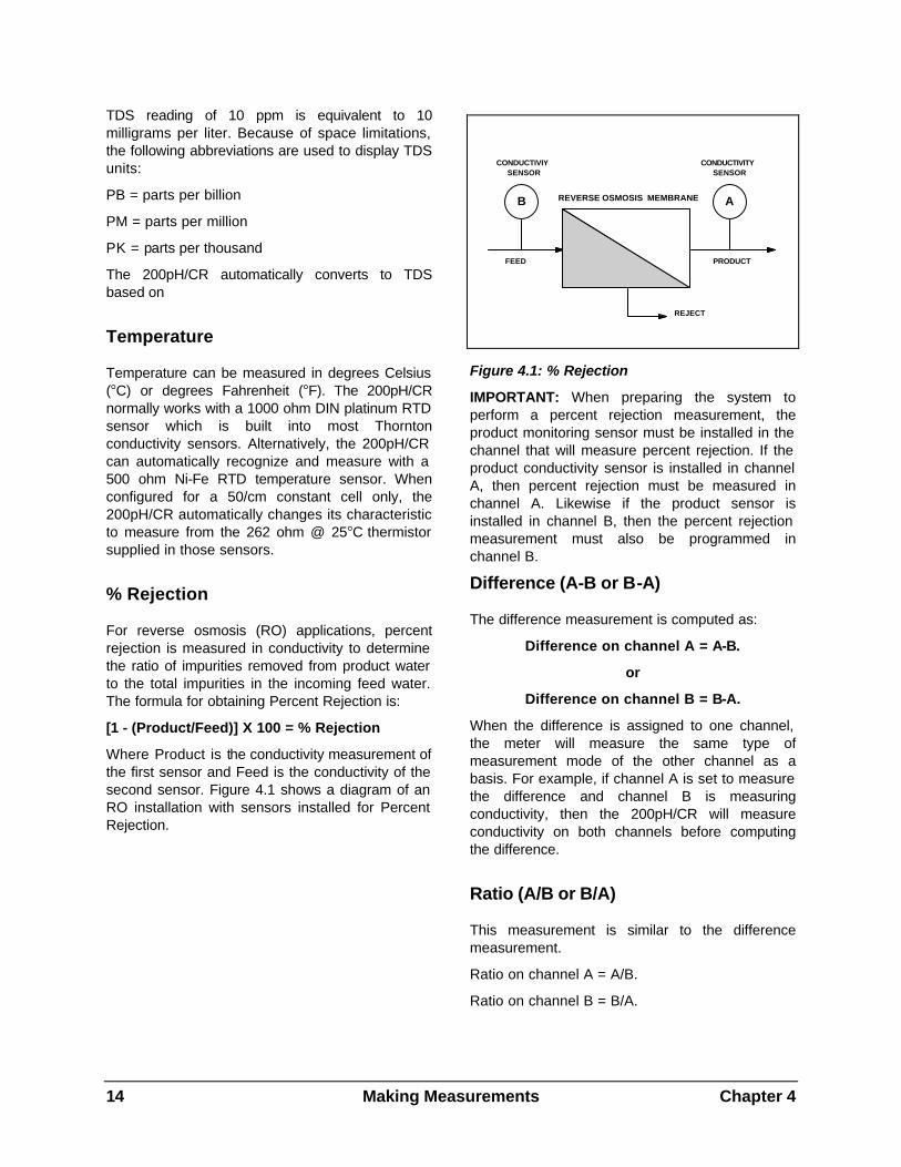
For reverse osmosis (RO) applications, percent rejection is measured in conductivity to determine the ratio of impurities removed from product water to the total impurities in the incoming feed water. The formula for obtaining Percent Rejection is:
[1 - (Product/Feed)] X 100 = % Rejection
Where Product is the conductivity measurement of the first sensor and Feed is the conductivity of the second sensor. Figure 4.1 shows a diagram of an RO installation with sensors installed for Percent Rejection.
REVERSE OSMOSIS MEMBRANE
FEED PRODUCT
REJECT
CONDUCTIVIYSENSOR
CONDUCTIVITYSENSOR
AB
Figure 4.1: % Rejection
IMPORTANT: When preparing the system to perform a percent rejection measurement, the product monitoring sensor must be installed in the channel that will measure percent rejection. If the product conductivity sensor is installed in channel A, then percent rejection must be measured in channel A. Likewise if the product sensor is installed in channel B, then the percent rejection measurement must also be programmed in channel B.
Difference (A-B or B-A)
The difference measurement is computed as:
Difference on channel A = A-B.
or
Difference on channel B = B-A.
When the difference is assigned to one channel, the meter will measure the same type of measurement mode of the other channel as a basis. For example, if channel A is set to measure the difference and channel B is measuring conductivity, then the 200pH/CR will measure conductivity on both channels before computing the difference.
Ratio (A/B or B/A)
This measurement is similar to the difference measurement.
Ratio on channel A = A/B.
Ratio on channel B = B/A.
Chapter 4 Making Measurements 15
Concentrations (%HCl, %NaOH, %H2SO4)
All concentrations are displayed as percent by weight. Setting a measurement for concentration automatically activates specialized temperature compensation for that particular material. The compensation setting is ignored for that channel.
SELECTING A MEASUREMENT TYPE
To set or change a measurement type for each of the four measurements:
Press the MEASURE MODE key and the display will show the measurement type assigned to channel A primary. The display may appear as:
A = Ω-cm (AUTO)
This menu indicates that channel A primary measurement is set for resistivity (Ω-cm) with auto ranging. The section “Ω -cm” is the first field to be changed and will be flashed as long as the cursor is under it. Pressing the UP arrow key will change the “Ω -cm” to “S/cm”.
A = S/cm (AUTO)
Use the UP and DOWN arrow keys to select the desired measurement type.
For conductivity, both temperature compensated and uncompensated measurement are available. Uncompensated readings are needed to meet pharmaceutical USP 23 requirements. Select units of “S/cm” for compensated measurement or “s/cm U” for uncompensated measurement. Using both primary and secondary parameters, both compensated and uncompensated measurements are available simultaneously. In normal operation, uncompensated measure-ments are identified by a flashing cursor under the units, for example, “µs”. Normal compensated readings are identified by “µS”.
The field on the right half side of the display is the range field. Some measurements can be set for a fixed range, others can be set only for auto ranging. For example, conductivity can be set for
micro, milli, units, or auto ranging. To change the field, use the RIGHT arrow key to move the cursor under “(Auto)”. Use the UP and DOWN arrow keys to select the desired range.
The OK/NEXT key is used to accept the entry for channel A primary and move to the next menu for setting channel “a” secondary. Press the OK/NEXT key a third and fourth time to set the measurement types for channel B primary and channel “b” secondary, respectively.
When the last menu level is reached (after setting channel “b” secondary), the following message is displayed:
Save Changes Yes
Pressing the OK/NEXT key will save the changes and exit the menus. The UP and DOWN arrow keys can be used to change the “Yes” to “No”. Pressing the OK/NEXT key with “No” will discard the changes and exit the menus.
CELL CONSTANTS
The calibration of each measurement is defined by a set of constants known as cell constants. There are two cell constants for each measurement: a Multiplier Factor and an Adder Factor. They are used to derive an accurate measurement from the sensor’s output signal. As an example, the output of a conductivity sensor can be represented by the following equation:
R =x/M + A
Where:
R = resistivity value
x = output from cell
M = multiplier factor
A = adder factor
Example: for a typical conductivity sensor the multiplier (M) is 0.1 and the adder (A) is 0. If the sensor output is 120,000 ohms, then the actual resistivity of the solution measured is 1.2 Mohm-cm and is calculated as follows:
R = x/M + A
R = 120,000/0.1 + 0
R = 1,200,000
16 Making Measurements Chapter 4
R = 1.2 Mohm-cm
NOTE: The adder is zero for conductivity, resistivity and ORP sensors.
The cell constants can be modified via the menus. For more information see ENTERING/EDITING CELL CONSTANTS in Chapter 9.
CONDUCTIVITY TEMPERATURE COMPENSATION
Conductivity, resistivity and TDS measurements can be compensated for temperature. Compensation will adjust the measurement to give an equivalent reading of the solution at 25°C. For example, the resistivity of ultrapure water at 25°C is18.18 MΩ-cm. The resistivity of ultrapure water at 30°C is 14.08 MΩ-cm. By compensating the resistivity reading, the value of pure water will continue to read 18.18 MΩ-cm.
The 200pH/CR can use one of nine different compensation methods: standard, linear, cation, alcohol, Light 84, 50% glycol, 100% glycol or none. Channels A and B can be programmed with different compensation methods.
For pharmaceutical USP <645> conductivity measurements where uncompensated measure-ment is required, select None for compensation. For simultaneous uncompensated and compensated measurements, see SELECTING A MEASUREMENT TYPE earlier in this chapter.
Standard Compensation
The standard compensation method includes compensation for non-linear high purity effects as well as conventional neutral salt impurities and conforms to ASTM standards D1125 and D5391.
Linear Compensation
The raw resistance measurement is compensated by multiplication with a factor expressed as a “% per °C” (deviation from 25°C). The range is 0 - 99%/°C with a default value of 2%/°C.
Cation Compensation
Power industry applications for cation conductivity measurements with acidic samples are accurately compensated with this setting. It takes into account the effects of temperature on the dissociation of pure water with the presence of very dilute acids. See ASTM Standard D6504 for recommendations on this measurement.
Semiconductor acid etch rinse operations are also more accurately monitored using this setting.
Ammonia / ETA Compensation
Power industry applications for specific or direct conductivity on samples with ammonia or ETA (ethanolamine) are accurately compensated with this setting. It takes into account the effects of temperature on the dissociation of pure water with these very dilute bases.
Alcohol Compensation
This compensation provides for the temperature characteristic of a 75% solution of isopropyl alcohol in pure water used for some rinsing operations in semiconductor manufacture. Compensated measurements using this solution may go well above 18 Mohm-cm.
Light 84 Compensation
This compensation matches the earlier high purity water research results of Dr. T.S. Light published in 1984. It is provided only for use by institutions that have standardized on that work. For all other pure water and general purpose applications, Standard Compensation (using the 1994 high purity water research of Thornton & Light) is recommended.
Glycol Compensation
This compensation matches the characteristics of 50% and 100% ethylene glycol in deionized water cooling/antifreeze solutions.
Chapter 4 Making Measurements 17
Setting conductivity compensation
Enabling the compensating feature is done via the menus as follows:
Press the MENUS key and the following menu will appear:
Menus use arrows
Press the UP arrow key until “Compensation” menu is displayed.
Compensation
Press the OK/NEXT key to access this menu.
A: Comp = Standard
The cursor will be initially placed under channel. Use the UP and Down arrow keys to change the channel if desired. Use the RIGHT arrow key to move the cursor to the method field. Use the UP and DOWN arrow keys to scroll through the list of available methods: “Standard”, “Linear”, “Cation”, “Alcohol”, "Light84" or “None”. Selecting “None” disables the compensation feature. Press the OK/NEXT key to accept the selection. If “Linear” is selected then another menu will be displayed where the linear value can be entered. This menu will appear as (the actual value may be different):
A: Comp = 2.000%/°C
Adjust the numerical field as desired using the arrow keys and press the OK/NEXT key when done. After setting the compensation state for channel A, repeat for channel B. Press OK/NEXT key when done. The meter will ask if changes should be saved.
Save Changes Yes
Press OK/NEXT key to save changes and return to the display of measurement data.
Compensation Indication
When displaying measurements, the 200pH/CR will indicate that a measurement is NOT
compensated by displaying a flashing underline cursor at the units character. The following display shows that channel A is compensated and channel B is not compensated (the character “µ” has a blinking underline cursor).
A1.76µS B2.11µS
pH TEMPERATURE COMPENSATION
The 200pH/CR Instrument provides two types of pH temperature compensation, described in following sections. If a temperature sensor is not included in a particular pH probe, a manual temperature setting or the temperature from the other channel sensor may be used instead. See Chapter 11.
With ORP measurement, temperature is not measured or compensated.
Conventional pH Electrode Temperature Compensation
Electrode Temperature Compensation (Nernst Response) is provided in most pH instruments. All pH electrodes produce a millivolt signal with gain proportional to the absolute temperature. Electrode temperature compensation normalizes that variable millivolt output to give pH values. The default and normal operating setting of the instrument has this compensation active. Some specialized measurements may need to disable it by accessing the "Compensation" setting via the MENUS key. Compensation for each channel may be individually turned on or off.
pH Solution Temperature Compensation
Solution Temperature Compensation allows settings for compensation of the variable ionization of pure waters. The change is so small in more conductive waters that it is usually ignored, but for high purity water, it is significant. It is used in addition to the conventional (Nernst) compensation, described above, which is normally active. Solution temperature compensation is used primarily with power plant and other pure water samples less than 30 µS/cm conductivity. It
18 Making Measurements Chapter 4
references the pH of pure water to 25°C. All other applications should leave the solution temperature coefficient (STC) set to its default value of zero.
For pure makeup water or boiling water reactor samples, the STC should be set to 0.016 pH/°C. For ammonia, phosphate and/or amine-treated samples the STC should be set to 0.033 pH/°C. The appropriate setting for other pure water compositions may be determined by developing temperature vs. pH data for the particular sample with the STC set to zero. The negative slope of this data becomes the STC value.
Because Solution Temperature Compensation is unique to the process sample and is different for buffer solutions, it is not active during calibration. The 200pH/CR ignores the STC during calibration. For this reason, the reading in a buffer solution after calibration may not be the exact value entered. To read and verify the exact buffer value, temporarily set the STC to zero.
The Solution Temperature Coefficient setting is accessed via the MENUS key / Spec pH Function / STC=0.000 pH/C for each channel.
pH Isopotential Point
The isopotential Point, IP, is left at the default setting of 7.0 for all Thornton and other conventional pH sensors. Special purpose pH electrodes with zero potential at values other than 7 pH will have this identified in their instruction manuals. A different IP setting will allow proper temperature compensation of these special electrodes. The IP setting is accessed via MENUS key / Spec pH Function / IP=7.000 pH for each channel.
AC POWER FREQUENCY
The 200pH/CR meter was designed to reduce fluctuations in measurements by eliminating noise pickup from the AC power line. The meter can be set to filter either 50Hz or 60Hz power from the measurements. Factory settings are 60 Hz for 115 VAC models and 50 Hz for 230 VAC models.
Setting 50/60 Hz Operation
To set the appropriate filter, press the MENUS key and the following menu will appear:
Menus use arrows
Press the DOWN arrow key until the “Set Frequency” menu is displayed.
Set Frequency
Press the OK/NEXT key to access this menu.
Frequency = 60
Use the UP or DOWN arrow keys to set the desired frequency. Press the OK/NEXT key when done. The meter will ask if changes should be saved.
Save Changes Yes
Press the OK/NEXT key to save the changes and return to the display of measurement.
Chapter 5 Using Setpoints 19
CHAPTER 5: USING SETPOINTS
OVERVIEW
A setpoint is a limit or alarm point applied to a measurement. A setpoint can be programmed as a high limit, a low limit or a USP limit. (A USP setpoint is a high alarm used for pharmaceutical water monitoring, described later in this chapter.) When the measurement value is higher than a high setpoint, or lower than a low setpoint, a setpoint error condition exists. The meter will indicate this condition by blinking the measurement on the display. The 200pH/CR can also be programmed to control a relay upon this error condition. Refer to Chapter 6 for more information on relays.
Four setpoints are available and can be assigned to any of the four measurements (A, a, B and b). More than one setpoint can be assigned to the same measurement and more than one setpoint can activate the same relay.
The following parameters can be programmed for setpoint operation:
1. The assigned signal: which signal (A, a, B, or b) is monitored by the setpoint.
2. The setpoint value: the measurement value that triggers the setpoint error condition, with prefix.
3. The setpoint type: High, Low, Off or USP.
4. The assigned relay: which relay will be controlled when a setpoint error occurs (this is optional).
5. Operation on overrange: Whether or not the setpoint will be active when the measurement is outside its range — yes or no.
SETPOINT SIGNAL
The setpoint signal is the measurement that will be monitored by the setpoint. The signal can be any of the measurements:
1. A - Channel A primary
2. a - Channel a secondary
3. B - Channel B primary
4. b - Channel b secondary
SETPOINT VALUE
The setpoint value is the limit that will trigger a setpoint error condition. This number is entered as a four digit number with a prefix. The prefixes are:
“µ” (micro) = multiply value by 0.000001 (10-6).
“m” (milli) = multiply value by 0.001 (10-3).
“-” (blank) = multiply value by 1
“K” (kilo) = multiply value by 1,000 (103).
“M” (Mega) = multiply value by 1,000,000 (106).
For example, a setpoint value of 18.18M is equivalent to 18,180,000.
When programming the setpoint values with TDS units, the following prefixes should be used (parts per million is the basis):
m = parts per billion
_ = parts per million
K = parts per thousand
SETPOINT TYPE
The setpoint type can be “High”, “Low”, "USP" or “Off”. A setpoint error condition occurs when the measurement is above the high or USP limit or below the low limit.
ASSIGNED RELAY
The assigned relay will change state according to the setpoint condition. When a setpoint error condition exists, the assigned relay will change state. If the relay is normally closed, then it will be opened.
Default settings after a system reset: Setpoints are disabled, no signals assigned, no relays assigned and values are zero.
PROGRAMMING A SETPOINT
20 Using Setpoints Chapter 5
Press the SETPOINTS key to access the first setpoint menu. This menu is used to assign a measurement to each of the four setpoints.
SP1 on signal: A
The cursor is under the setpoint number field. Use the UP and DOWN arrow keys to select the desired setpoint number (1 to 4). Use the RIGHT arrow key to move the cursor to the signal field. Then use the UP and DOWN arrow keys to select the desired signal. The signal can be set to “-” which indicates that the setpoint is not assigned (disabled).
To change the assigned signal of another setpoint, move the cursor back to the setpoint number. Change the setpoint number, then move the cursor back to the assigned signal field.
SP1=.0000 _ off
Press the OK/NEXT key when done to proceed to the next menu.
The cursor is initially under the setpoint number field. Select the desired number then move the cursor to the numerical field. Set the desired value and prefix.
Examples of numerical entries:
Desired Value
Menu Entry
10.34 10.34_
1,456 1.456K
18,180,000 18.18M
567,456 567.5K
0.003 .0030_ or 3.000m
.000000055 .0550µ
Move the cursor over to the setpoint type field. To turn the setpoint on, select High, Low or USP. Press the OK/NEXT key when done to proceed to the next menu.
The next menu is used to assign a relay to the setpoint. This is optional. The menu will appear as:
SP1 use Relay#_
After selecting the desired setpoint number, move the cursor to the relay field. The choices are: 1 - 4 and “_”. The “_” indicates that there are not any relays assigned to the setpoint.
NOTE: Some models of the 200pH/CR are equipped with only 2 relays and will allow settings of only #1 or #2.
Press the OK/NEXT key when done to proceed to the next menu.
SP1 over-range Yes
This menu selects whether the setpoints will be active when the measurement is out of range, which could be due to process upset, loss of fluid at the sensor, disconnected sensor leads, etc. Use the arrow keys to select Yes or No for each setpoint.
Press the OK/NEXT key when done. The meter will ask if changes should be saved.
Save Changes Yes
Press the OK/NEXT key to save the changes and return to the display of measurement data.
Example: Set Up a Setpoint
Program setpoint #2 with the following conditions:
1. Assigned to channel A secondary signal (“a”).
2. A value of 18,200,000 (18.2 M Ω-cm)
3. Set as a high limit
4. Use relay #2
5. Disabled when out of range
Chapter 5 Using Setpoints 21
Press the SETPOINTS key
Use the arrow keys to select setpoint #2 and signal “a”. The display will appear as follows:
SP2 on signal: a
Press the OK/NEXT key:
Use the arrow keys to set the value at 18.20M and the state to high. The display will appear as follows:
SP2=18.20 M High
Press the OK/NEXT key:
Use the arrow keys to set the relay number to 2. The display will appear as follows:
SP2 use Relay #2
Press the OK/NEXT key:
Use the arrow keys to set the over-range to No, resulting in the following display:
SP2 over-range No
Press the OK/NEXT key. The meter will ask if changes should be saved.
Save Changes Yes
Press the OK/NEXT key to save the changes and return to the display of measurement data.
USP SETPOINT
The USP type setpoint is a high alarm used for pharmaceutical water monitoring with non-temperature compensated conductivity measurements. USP (United States Pharmacopoeia) section <645> requires that non-temperature compensated conductivity of pharmaceutical waters must be below a limit from its table based on the temperature of the sample. In other words, USP requirements are to temperature compensate the limit rather than the measurement.
The 200pH/CR instrument has the USP 23 table in memory and automatically determines the conductivity limit based on the measured temperature.
The USP setpoint value set in the 200pH/CR is the percentage safety margin below the USP limits to activate the setpoint. For example, the USP table conductivity limit at 15°C is 1.0 µS/cm. If the setpoint value is set at 40% then the setpoint will activate whenever the conductivity goes above 0.6 µS/cm at 15°C.
USP <645> Stage 1 Conductivity Limits as a Function of Temperature
Temperature (°C)
Conductivity Limit (µS/cm)
0 0.6 5 0.8 10 0.9 15 1.0 20 1.1 25 1.3 30 1.4 35 1.5 40 1.7 45 1.8 50 1.9 55 2.1 60 2.2 65 2.4 70 2.5 75 2.7 80 2.7 85 2.7 90 2.7 95 2.9
100 3.1
To configure a USP setpoint, use the previous procedure but select USP instead of High or Low. When selected, the display appears as:
SP1=0.000 % USP
Using the arrow keys, enter the percent safety margin below the USP conductivity limit desired.
22 Using Relays Chapter 6
CHAPTER 6: USING RELAYS
DESCRIPTION
The 200pH/CR is equipped with up to four relays. Each relay can be programmed to activate when a setpoint is exceeded (defined as a setpoint error condition). The programmable parameters for a relay are:
1. Delay Time: up to 999 seconds
2. Hysteresis Value: up to 99%
3. State: normal or inverted
ELECTRICAL CONNECTIONS
For units equipped with two relays, each one has a common connection, a normally open connection and a normally closed connection. Units with 3rd and 4th solid state relays have only a common connection and a normally open connection as shown in Table 2.1.
DELAY TIME
Delay time is the length of time that the setpoint must be exceeded continuously (in a setpoint error condition) before activating the relay. When the setpoint error condition occurs, the delay timer is started. If during the delay time the setpoint error condition no longer exists, the delay timer is reset and the relay will not be activated. The maximum delay time is 999 seconds (16 minutes and 39 seconds).
HYSTERESIS
The hysteresis value is entered as a percentage of the setpoint value. For a high setpoint, the measurement must fall more than this percentage point below the setpoint value before the relay is deactivated. With a low setpoint, the measurement must rise at least this percentage above the setpoint value before the relay is deactivated.
For example: a high setpoint is set at 100 and the measurement is currently above this value so the setpoint error condition exists. If the hysteresis
value is 10% then the measurement must fall below 90 before the relay is deactivated.
RELAY STATE
The relay can be programmed for normal or inverted operation. When the relay is in the inverted state, the relay operation is reversed. When there is no setpoint error condition the relay is activated. The normally open contacts are closed.
WARNING: RELAYS WILL ALWAYS DE-ENERGIZE ON LOSS OF POWER, EQUIVALENT TO NORMAL STATE, REGARDLESS OF RELAY STATE SETTING. HOWEVER, THE SETTING IS RETAINED ON RESTORATION OF POWER.
Default settings after the system reset:
1. Relay is disabled.
2. Delay is 0 seconds.
3. Hysteresis is 0%.
4. Relay state is normal.
PROGRAMMING A RELAY
To enable or modify a relay:
Press the RELAYS key. The first relay menu is used to set the delay time.
R1 Delay= 000 sec
In this menu, the cursor is initially under the relay number. Use the UP and DOWN arrow keys to select the desired relay number (1 to 4). Use the RIGHT arrow key to move the cursor to the delay time field. Then use the UP and DOWN arrow keys to set the delay time (000 to 999 seconds).
To change the delay time of another relay, move the cursor back to the relay number. Change the relay number, then move the cursor back to the relay time field.
Press the OK/NEXT key when done to proceed to the next menu.
Chapter 6 Using Relays 23
R1 Hyster = 00%
Select the desired relay number and enter the hysteresis value (00 to 99%).
Press the OK/NEXT key when done to proceed to the next menu.
R1 State = Normal
Select the desired relay number, then use the DOWN arrow key to select either Normal or Invert. Press the OK/NEXT key when done. The meter will ask if changes should be saved.
Save Changes Yes
Press the OK/NEXT key to save the changes and return to the display of measurement data.
Example: Setup a Relay
Program relay #2 with the following conditions:
1. Delay of 60 seconds.
2. A hysteresis of 10%.
3. Inverted state.
Press the RELAYS key.
Use the arrow keys to select relay #2 and set a delay time of “060”. The display will appear as follows:
R2 Delay = 060 sec
Press the OK/NEXT key.
Use the arrow keys to set the hysteresis value to “10%”. The display will appear as follows:
Press the OK/NEXT key.
R2 Hyster = 10%
Use the arrow keys to set the state to inverted. The display will appear as follows:
R2 State = Invert
Press the OK/NEXT key. The meter will now ask if changes should be saved.
Save Changes Yes
Press the OK/NEXT key to save the changes and return to the display of measurement data.
24 Using Analog Outputs Chapter 7
CHAPTER 7: USING ANALOG OUTPUTS
DESCRIPTION
An analog output is an isolated current signal that is proportional to any measurement. The two 200pH/CR analog outputs have a minimum value of 4mA and a maximum value of 20mA (the signal can be re-calibrated to 0-20mA when needed, see ANALOG OUTPUT CALIBRATION later in this chapter). Each output can be scaled to a range of a measurement signal.
To use analog outputs, the following parameters must be programmed:
1. Assigned Signal - The analog output will be proportional to the value of the assigned signal. Any of the four measurements (A, a B, b) can be assigned to the output.
2. Minimum Value - This is the measurement reading that will correspond to an output of 4mA.
3. Maximum Value - This is the measurement reading that will correspond to an output of 20mA.
The analog outputs can be programmed for their minimum and maximum values. This programming process is independent from any measurement. See PROGRAMMING THE ANALOG OUTPUTS later in the chapter for details.
ELECTRICAL CONNECTIONS
Connections to the analog output signals are made at terminal block TB2. Each analog output channel has a signal line (labeled AO1+ or AO2+) and a return line (labeled AO1- or AO2-). Table 2.4 shows the electrical connections.
The minimum can be re-calibrated down very close to zero mA when needed. See ANALOG OUTPUT CALIBRATION later in this chapter.
The analog outputs are isolated from line power, sensors and earth ground. Each analog output channel can drive a resistive load up to 500 ohms.
PROGRAMMING THE ANALOG OUTPUTS
To set up an analog output channel, press the OUTPUTS key:
Output: Analog
Press the OK/NEXT key to access this menu. The next menu is used to assign a measurement signal to the output. The choices are: A, a, B, b, and _. The selection of “_” is used to disable the output by not assigning a signal to the output. The output will remain at 4mA when it is disabled. The menu may appear as:
Aout1 signal = A
In this menu the cursor is initially under the output number. Use the UP or DOWN keys to select the desired output number ( 1 or 2). Press the RIGHT arrow key to move the cursor under the assigned field.
Aout1 signal = A
Use the UP or DOWN arrow keys to change the assigned measurement. Press the OK/NEXT key to accept it and proceed to the next menu.
Aout1 Min=0.000_
This menu is used to set the measurement value that will correspond to a 4mA output. Set the desired value. The last position in this menu is the prefix which can be one of the following:
“µ” (micro) = multiply value by 0.000001 (10-6).
“m” (milli) = multiply value by 0.001 (10-3).
“_” (blank) = multiply value by 1.
“K” (kilo) = multiply value by 1,000 (103)
“M” (Mega = multiply value by 1,000,000 (106)
Chapter 7 Using Analog Outputs 25
When programming the analog output scaling limits with TDS units, the following prefixes should be used (parts per million is the basis):
m parts per billion
_ parts per million
K parts per thousand
After setting the desired value, press the OK/NEXT key to accept minimum value and proceed to the next menu.
Aout1 Max=1.000_
This menu is used to set the measurement value that will correspond to an output of 20mA. Repeat the process as described above. Press the OK/NEXT key to accept the maximum value and proceed to the next menu.
1:If err set Max
Using an arrow key, select max or min as the fail safe mode for the output signal on overange or failure conditions. The output will go to 20mA if set for max; to 4mA (or 0mA if re-calibrated) if set for min. The meter will ask if changes should be saved.
Save Changes Yes
Press the OK/NEXT key to save the changes and return to the display of measurement data.
Example: Setup an Analog Output
Set analog output #2 with the following parameters:
1. Assigned to channel B primary measurement
2. Minimum value of 1.000 M ohms
3. Maximum value of 20.00 M ohms
Press the OUTPUTS key. The display will show:
Output: Analog
Press the OK/NEXT key.
Use the arrow keys to select analog output #2 and assign measurement B to this output. The display will appear as follows:
Aout2 signal = B
Press the OK/NEXT key.
Use the arrow keys to set the minimum value to 1.000 M ohms. The display will appear as follows:
Aout2 Min=1.000M
Press the OK/NEXT key.
Use the arrow keys to set the maximum value to 20.00 M ohms. The display will appear as follows:
Aout2 Max=20.00M
Press the OK/NEXT key.
Save Changes Yes
Press the OK/NEXT key to save changes and return the display of measurement data
ANALOG OUTPUT CALIBRATION
The analog output signals have been factory calibrated to specifications and normally do not require any further adjustment. To match other equipment, they may be re-calibrated in a two step process where 4mA and 20mA levels are adjusted. A current meter is connected in series with the output. The arrow keys are then used to adjust the current output for the appropriate level (4mA, then 20mA).
The 4mA end of the signal can be calibrated down to zero mA, where needed. With a 500 ohm resistor across the output terminals, a 0-10 VDC signal may also be obtained.
For NIST traceability, the outputs can be calibrated with any NIST-calibrated current meter.
Procedure: Connect the meter in series with the output signal.
Press the CAL key and the display will show:
Calibrate Sensor
26 Using Analog Outputs Chapter 8
Use the UP and DOWN keys to change the display until the “Analog” option is displayed:
Calibrate Analog
Press the OK/NEXT key to proceed to the next menu.
Cal Analog Ch 1
Use the UP and DOWN keys to select the desired output channel number (1 or 2). Press the OK/NEXT key to proceed to the next menu.
1:Adj 4mA=10641
Use the UP and DOWN keys to adjust the output current for a 4mA level (as measured by the current meter). The number displayed is an arbitrary value proportional to the analog output signal, near 10,000 for 4 mA, near 0.000 for 0 mA and near 55,000 for 20 mA. Adjusting a more significant digit of this number will change the output signal level faster. Adjust a less significant digit for closer resolution.
Press the OK/NEXT key when done adjusting the 4mA or 0mA output. The next menu is for adjusting the 20mA output.
1:Adj 20mA=54091
Adjust the 20mA level in a similar manner. Press the OK/NEXT key when done adjusting the 20mA. The meter will ask if changes should be saved.
Save Changes Yes
Press the OK/NEXT key to save the changes and return to the display measurement data.
Chapter 8 Meter Calibration 27
CHAPTER 8: METER CALIBRATION
OVERVIEW
The 200pH/CR meter is factory calibrated within specifications. It is not necessary to perform meter re-calibration unless extreme conditions cause out of specification operation shown by Verification (see CALIBRATION VERIFICATION section). Periodic verification/re-calibration may also be necessary to meet Q.A. requirements. ALWAYS perform a verification before considering a meter calibration. If within specification there is no need to perform a meter calibration.
CAUTION: Do not perform a meter calibration unless a Thornton calibrator or precision decade box is connected. Factory calibration cannot be restored in the field.
The 200pH/CR meter is re-calibrated for conductivity/resistivity by installing a known resistance value in place of the cell and using the calibration menus to complete the process. The meter is designed for calibration at six points for conductivity/resistivity and two points of temperature (on each channel) as shown in Table 8.1. The second column of the table indicates the calibrators that are applicable for a region of measurement. Note that a single conductivity/resistivity calibration covers both Channels A and B at one time but separate temperature calibrations are required on each channel.
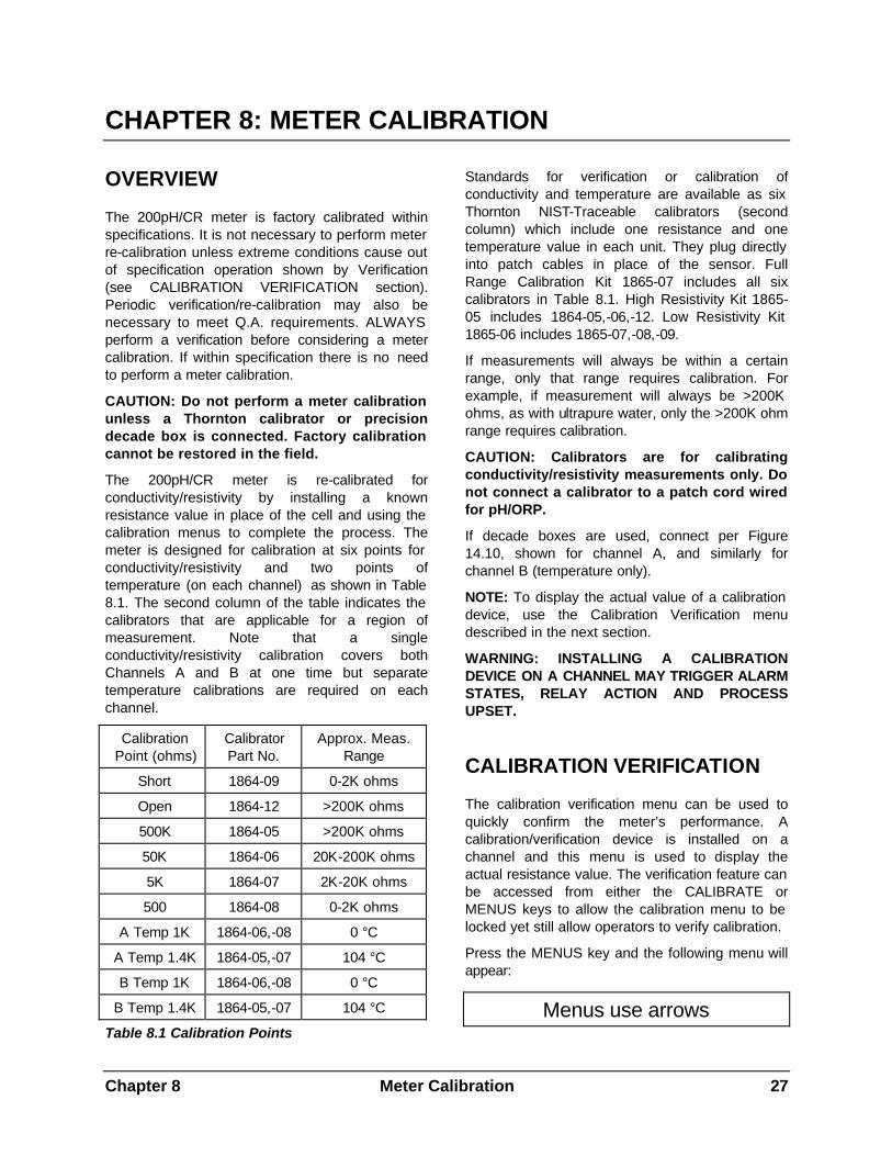
Calibration Point (ohms)
Calibrator Part No.
Approx. Meas. Range
Short 1864-09 0-2K ohms
Open 1864-12 >200K ohms
500K 1864-05 >200K ohms
50K 1864-06 20K-200K ohms
5K 1864-07 2K-20K ohms
500 1864-08 0-2K ohms
A Temp 1K 1864-06,-08 0 °C
A Temp 1.4K 1864-05,-07 104 °C
B Temp 1K 1864-06,-08 0 °C
B Temp 1.4K 1864-05,-07 104 °C
Table 8.1 Calibration Points
Standards for verification or calibration of conductivity and temperature are available as six Thornton NIST-Traceable calibrators (second column) which include one resistance and one temperature value in each unit. They plug directly into patch cables in place of the sensor. Full Range Calibration Kit 1865-07 includes all six calibrators in Table 8.1. High Resistivity Kit 1865-05 includes 1864-05,-06,-12. Low Resistivity Kit 1865-06 includes 1865-07,-08,-09.
If measurements will always be within a certain range, only that range requires calibration. For example, if measurement will always be >200K ohms, as with ultrapure water, only the >200K ohm range requires calibration.
CAUTION: Calibrators are for calibrating conductivity/resistivity measurements only. Do not connect a calibrator to a patch cord wired for pH/ORP.
If decade boxes are used, connect per Figure 14.10, shown for channel A, and similarly for channel B (temperature only).
NOTE: To display the actual value of a calibration device, use the Calibration Verification menu described in the next section.
WARNING: INSTALLING A CALIBRATION DEVICE ON A CHANNEL MAY TRIGGER ALARM STATES, RELAY ACTION AND PROCESS UPSET.
CALIBRATION VERIFICATION
The calibration verification menu can be used to quickly confirm the meter’s performance. A calibration/verification device is installed on a channel and this menu is used to display the actual resistance value. The verification feature can be accessed from either the CALIBRATE or MENUS keys to allow the calibration menu to be locked yet still allow operators to verify calibration.
Press the MENUS key and the following menu will appear:
Menus use arrows
28 Meter Calibration Chapter 8
Press the DOWN arrow key until the “Verify Calibrate” menu is displayed.
Calibrate Verify
Press the OK/NEXT key to access this menu.
Verify Cal: Ch A
Use the UP arrow key to select the desired channel. Press the OK/NEXT key when set. The meter will now display the actual values of the calibrator. A typical display may appear as:
A10.04MΩ 1.003KΩ
The first number is the measured value of the conductivity/resistivity input and the second number is the measured value of the temperature input. Compare these numbers with the values printed on the label of the verifier/calibrator as well as on the Certificate of Accuracy supplied with it. Values should be within ±0.5%. Press any key to end this menu. Other calibration/verification values may be checked in the same manner. If within specification, do not perform a calibration.
CALIBRATION PROCEDURE
The resistance calibration sequence should use the "short" and/or "open" calibrators first, whenever they are used. Other calibrators may be used in any order.
Step 1: Select the Meter Calibration
Press the CALIBRATE key and the display will show:
Calibrate Sensor
Use the UP and DOWN keys to change the display until it reads:
Calibrate Meter
Press the OK/NEXT key to proceed to the next menu.
Step 2: Select the channel
Cal Meter Ch A
Use the UP and DOWN keys to select channel B if desired (for temperature). Press the OK/NEXT key to proceed to the next menu.
Step 3: Select the signal to calibrate:
Cal A #1: R 500K
Use the UP and DOWN keys to select the point to be calibrated. The choices are: “R500K", "R50K", "R5K", "R500", “Temp”, "Volts", "Short", or “Open”. Press the OK/NEXT key when ready to proceed to the next menu.
For the following example "Temp" is selected for calibration.
Cal A #1: Temp
Step 4: Enter the calibrator value:
A Temp =1.0000K
This menu is used to enter the value of the calibrator (printed on the label as well as the Certificate of Accuracy supplied with the calibrator). The display will show a nominal value but the actual value of the calibrator must be entered. Use the UP and DOWN keys to change the digit. Use the RIGHT and LEFT arrow keys to move the cursor to the next digit. The last character on the display is the units prefix, which appears after the value on the calibrator.
For Reference:
The available prefixes are “µ” = micro, “m” = milli, “k” = kilo, “M” = mega and “_” = one. The numerical entry is multiplied by the value of the prefix as follows:
“µ” (micro) = multiply value by 0.000001 (10-6).
“m” (milli) = multiply value by 0.001 (10-3).
“_” (blank) = multiply value by 1.
“K” (kilo) = multiply value by 1,000 (103)
“M” (Mega = multiply value by 1,000,000 (106)
Chapter 8 Meter Calibration 29
When the value of the calibrator is entered, press the OK/NEXT key when ready to proceed to the next menu.
Step 5: Install the calibrator on the selected channel:
A= 1.0003KT Ω OK?
The instrument will display the value of the calibrator as measured by the meter. it is important to wait for this displayed measurement to stabilize. The reading may fluctuate slightly but the changes should be no more than +1 digit (least significant). For example, in the display above the reading may fluctuate from 1.0002K to 1.0004KΩ. It is recommended that you wait at least 30 seconds to be certain that the measurement has settled.
To discontinue the calibration, press any of the menu keys. To proceed with the calibration process (after the readings have stabilized), press the OK/NEXT key.
Step 6: Perform the calibration:
The calibration process may take a few seconds to complete. When the instrument is done, the following message will be displayed.
Done, press OK
Step 7: Proceed to the 2nd calibration point:
Press the OK/NEXT key to complete the calibration of the first point. The meter will display the following menu:
Do point #2 No
Press the OK/NEXT key to save the new calibration factor and return to the measurement mode. Otherwise, use the UP and DOWN arrow keys to change the “No” to “Yes” and press the OK/NEXT key to perform calibration for a 2nd point. The meter will display the following menu, requesting the value of the 2nd calibration point:
Step 8: Enter the calibrator value (point #2)
A Temp = 1.4000K
Enter the exact value of the 2nd calibrator and press the OK/NEXT key when ready to proceed.
Step 9: Install the second calibrator:
As with the 1st calibration point, the meter will now display the measured value of the calibrator as follows:
A=1.4011KTΩ OK?
When the reading has stabilized, press the OK/NEXT key.
Step 10: Perform the calibration (point #2):
The calibration process may take a few seconds to complete. When the instrument is done, the following message will be displayed:
Done, press OK
Press the OK/NEXT key. The meter will ask if the changes should be saved.
Save Changes Yes
Press the OK/NEXT key to save the changes and return to the display of measurement data.
The calibration process is complete for the temperature circuit of one channel. Repeat this process for the other channel temperature, if used, and for the conductivity/resistivity points.
Reminder: due to entered cell constants and temperature compensation, the meter will only read the exact connected calibrator value in the “Verify” mode.
Special Temperature Calibration
NOTE: If using 2_8 series Dot Two cells with Ni-Fe 500 ohm RTD, substitute a decade box with 500 ohms for 0°C and 735 ohms for 100°C in place of the calibrators in the previous procedure.
30 Meter Calibration Chapter 8
Voltage Calibration for pH and ORP
It is generally not necessary to calibrate the voltage range which is used for pH measurement. pH sensor calibration is performed frequently in NIST traceable pH buffer solutions and will override any voltage calibration. (The pH scale is defined by response in NIST standard reference materials.)
The voltage input is used with ORP sensors. To calibrate the voltage range, use a stable voltage source and precision voltmeter and connect as given in Figure 14.10. Follow the procedure above, selecting "Volts" as the signal to be calibrated. A two-point calibration should be done near -400 and +400 mV. A 200pH/CR meter voltage calibration cannot be done at zero millivolts.
Chapter 9 Sensor Calibration 31
CHAPTER 9: SENSOR CALIBRATION
CONDUCTIVITY/RESISTIVITY CELL CONSTANTS
Best performance is normally obtained by entering the factory-documented cell constants in the Entering/Editing Cell Constants sections below. Cell constants are provided on the label of the sensors and on their certificates of calibration.
However, if the sensor’s performance is not acceptable then it can be calibrated. It is important to ensure that the meter is properly calibrated and that a very accurate standard solution is available before performing a sensor calibration described at the end of this chapter.
Entering/Editing Conductivity/ Resistivity Cell Constants
Upon the installation of a conductivity cell, the cell constants must be entered into the meter. Channel A has two cell constant types: one for the resistivity/conductivity sensor and one for the temperature sensor. These constants are referred to as “A Cell” and “A Temp”, respectively. Each of these types has a Multiplier and an Adder cell constant. Channel B has similar constants (“B Cell” and “B Temp”). Only the Multiplier factor is used for conductivity/resistivity and temperature. The Adder factors are left at zero.
The procedure to enter and edit constants is as follows:
Press the MENUS key and the following menu will appear:
Menus use arrows
Press the UP arrow key until “Edit Sensor Cal” menu is displayed.
Edit Sensor Cal
Press the OK/NEXT key to access this menu
A Cell M=.10000_
The cursor is initially under the channel/type field. Use the UP arrow key to select the desired channel/type (either “A Cell”, “A Temp”, “B Cell”, “B Temp”).
The next field selects either the Multiplier, M, or the Adder, A, factor.
A Cell M=.10000_
Use the RIGHT arrow key to move the cursor to the number field. Use the arrow keys to enter the cell constants from the sensor label. The last position in the menu is a unit prefix which should be left at “_” (blank or units); although µ (micro), m (milli), K (Kilo) and M (mega) are also available.
After setting the desired value, the RIGHT arrow key can be used to move the cursor back to the channel/type field (1st field) so that the other constants can be entered and edited. The changes are recorded when you proceed to a different constant.
Pressing the OK/NEXT key will accept all set values. The meter will ask if changes should be saved.
Save Changes Yes
Press the OK/NEXT key to save the changes and return the display to measurement mode.
CONDUCTIVITY/RESISTIVITY SENSOR CALIBRATION
Conductivity sensors can be calibrated with either a one-point or two-point calibration process. With a two-point process, the sensor must be put in two different solutions (or temperature values). Under most circumstances only a 1 point calibration process is recommended.
The solution must be known with very high accuracy (either resistivity, conductivity, °C or °F) before the sensor can be calibrated. Calibration is accomplished by entering the known solution value into the meter and instructing the meter to perform a calibration.
32 Sensor Calibration Chapter 9
When a one-point calibration is performed, the meter will compute a new sensor Multiplier factor. With a two-point calibration, the meter will compute new Multiplier and Adder factors.
Conductivity/resistivity sensor calibration cannot be done if the measurement is set for untemperature compensated conductivity (see SELECTING A MEASUREMENT TYPE in Chapter 4). If necessary, temporarily set the instrument for compensated measurement for the calibration. (Calibration can be done, if desired, with Compensation set to “None”, accessed by the MENUS key)
NOTE: The 240-501 cell with 50/cm cell constant uses a 262.4 ohm @ 25°C thermistor. With this sensor, use the factory temperature multiplier constant provided on the cell leadwire label. No further temperature calibration is possible. (Conductivity calibration may be performed in the normal manner.)
Conductivity/ Resistivity Calibration Procedure
Press the CALIBRATE key and the display will show:
Calibrate Sensor
Press the OK/NEXT key to proceed to the next menu.
Cal Sensor Ch A
Use the UP arrow key to select the desired channel. Press the OK/NEXT key when set.
Cal Ch A #1: Res
Use the UP arrow key to select the measurement to be calibrated. The choices are: Res, Con, pH, Volts, °C and °F. Press the OK/NEXT key when set.
The next menu will allow the known value of the signal (or solution) to be entered.
A Res = 18.180 M
Enter the known value. Be certain to set the proper units prefix. In this example, the prefix is “M” for Megohms. Press the OK/NEXT key when done.
The meter will now display the reading of the signal to be calibrated. For example, a typical display for calibrating resistivity may appear as:
A= 18.15MΩ OK?
When the reading has stabilized, press the OK/NEXT key to perform the calibration. The calibration process may take a few seconds to complete. When the instrument is done, the following message will be displayed:
Done, press OK
Press the OK/NEXT key. The meter will display the menu for performing the second calibration point.
Do point #2 No
If doing a two-point calibration, then use the UP key to change the “No” to “Yes”. Press the OK/NEXT key to perform the 2nd calibration point or to exit the menus.
NOTE: Performing a sensor calibration will modify the cell constants shown in the "Edit Sensor Cal" menu such that they will not match the constants written on the cell label.
Chapter 9 Sensor Calibration 33
PH/ORP SENSOR CALIBRATION
Overview
Periodic sensor calibration is necessary because pH sensors have some variation in output which can change over time, especially under harsh or contaminating process conditions. The frequency of calibration must be determined by experience with a particular application. For example, begin with daily calibration, then extend to weekly, then to monthly, bi-monthly, etc. as allowed by the drift experienced and process accuracy requirements. Such a sequence is also appropriate since new sensors will show some initial drift as they acclimate to the process. The accuracy of calibration is determined by the accuracy and traceability of the standard buffer solutions used.
At initial sensor installation, acceptable performance can usually be obtained by entering the factory-documented sensor constants from the sensor label as described. This allows startup without standard buffer solutions. However, if accuracy must be optimized and for subsequent calibration, the regular procedures must be followed.
Calibration is accomplished by entering the known value into the instrument and instructing it to perform the calibration. When a one-point calibration is performed, the instrument computes a new Adder (standardize offset or zero) constant. With a two-point calibration, the instrument computes new Adder and Multiplier (slope or span) constants. It should be noted that a non-functional sensor can always be calibrated at one point. Response to a changing process or a second calibration point are needed to ensure the sensor is functioning.
For ORP measurement, no sensor calibration is recommended although it is possible. It is recommended that the instrument read in absolute millivolts established by factory meter calibration. The Adder constant is left at 0 and the Multiplier at 1.0. Standard ORP solutions are available for checking operation of sensors, however, their tolerance under process conditions is generally too wide to be useful for calibration.
Two methods are used for pH sensor calibration: buffer and grab sample. In some situations, it is
most convenient to do a grab sample calibration on a routine basis. A two-point buffer calibration may be performed at less frequent intervals to provide full adjustment to sensor response.
Buffer calibration requires removal of the sensor from the process and immersing it in standard buffer solution. It may be done at one or two points and gives the most direct traceability to the standard(s). The sensor should be rinsed well with deionized or distilled water before immersing in each standard.
With the sensor removed from the process during buffer calibration, analog outputs and alarm relays are uncontrolled. Provide external means to disable any alarm or control action that could disrupt the process.
Grab sample calibration allows the sensor to remain in the process but is limited to a one-point procedure. A sample is removed and measured by a portable pH system that has been previously calibrated in standard buffer solutions. The process pH must be stable enough that there is high confidence that a sample will be representative of the on-line value. For pure water samples (<20 µS/cm conductivity), the "grab sample" should be a flowing side stream not exposed to air before measurement, to minimize carbon dioxide contamination.
The steps for grab sample calibration are as follows:
1. Record the displayed pH at the time the grab sample is taken.
2. Measure the grab sample pH.
3. Calculate the difference of the grab sample pH minus the recorded process pH, retaining the sign (positive or negative).
4. Add the difference value to the current displayed process pH and immediately enter the result as the calibration standard value in the procedure.
Example:
1. The 200pH/CR instrument reads 6.50 pH when the grab sample is taken.
2. The grab sample measures 6.20 pH on the portable system.
3. The difference is - 0.30 pH.
34 Sensor Calibration Chapter 9
4. The current 200pH/CR instrument reading is 7.00 pH so 6.70 pH is the value entered for one-point calibration.
pH Calibration Procedure
Press the CALIBRATE key and the display will show:
Calibrate Sensor
Press the OK/NEXT key to proceed to the next menu.
Cal Sensor Ch A
Use the UP arrow key to select the desired channel. Press the OK/NEXT key when set.
Cal Ch A #1: pH
Use the UP arrow key to select the measurement to be calibrated. The choices are: pH, Volts, Res, Con, °C and °F. Press the OK/NEXT key when set.
The next menu will allow the known value of the signal (or solution) to be entered.
A pH = 4.000 _
Using the arrow keys, change the display to the solution value. For buffer solutions, enter the exact pH value corresponding to its temperature.
Press the OK/NEXT key. The meter will now display the uncalibrated reading to check for stability only. The actual value of the calibration will appear only after completion of the procedure. For example, a typical display may appear as:
A= 3.925 OK?
When the reading has stabilized, press the OK/NEXT key to perform the calibration. The calibration process may take a number of seconds to complete. When the instrument is done, the following message will be displayed:
Done, press OK
Press the OK/NEXT key. The meter will display the menu for performing the second calibration point.
Do point #2 No
If doing a two-point calibration, use the UP key to change the “No” to “Yes”. Press the OK/NEXT key to perform the 2nd point of calibration similar to the first. For a single point calibration, press OK/NEXT with “No” in the display above to exit the menus.
NOTE: Performing a sensor calibration will modify the cell constants shown in the "Edit Sensor Cal" menu such that they will not match the constants written on the sensor label.
Entering/Editing pH Calibration Constants
Upon the installation of a pH sensor, its calibration constants are entered into the 200pH/CR, especially when buffer solutions are not available. Channel A has two constant types: one for the pH sensor and one for the temperature sensor. These constants are referred to as “A Cell” and “A Temp”, respectively. Each of these types has a Multiplier and Adder cell constant. Channel B has similar constants (“B Cell” and “B Temp”). Only the Multiplier factor is used for temperature. Its Adder factor is left at zero.
The procedure to enter and edit the constants is as follows:
Press the MENUS key and the following menu will appear:
Menus use arrows
Press the UP arrow key until “Edit Sensor Cal ” menu is displayed.
Edit Sensor Cal
Press the OK/NEXT key to access this menu
A Cell M=1.0000_
The cursor is initially under the channel/type field. Use the UP arrow key to select the desired channel/type (either “A Cell”, “A Temp”, “B Cell”, “B Temp”).
Chapter 9 Sensor Calibration 35
The next field selects either the multiplier, M, or the adder, A, factor.
A Cell M=.10000_
Use the RIGHT arrow key to move the cursor to the number field. Use the arrow keys to modify the number desired. The last position in the menu is a unit prefix which should be left at “_” (blank); although µ (micro), m (milli), K (Kilo) and M (mega) are also available.
After setting the desired value, the RIGHT arrow key can be used to move the cursor back to the channel/type field (1st field) so that the other constants can be entered and edited. The changes are recorded when you proceed to a different constant.
Pressing the OK/NEXT key will accept all set values. The meter will ask if changes should be saved.
Save Changes Yes
Press the OK/NEXT key to save the changes and return the display of measurement data.
PH SENSOR DIAGNOSTICS
The Adder and Multiplier constants described above can provide valuable preventive maintenance information about the sensors.
The Adder factor (zero, asymmetry or standardize offset) is an indication of how far the sensor has drifted from the nominal zero starting point, in pH units. It is recalculated after ever calibration. Drift in this value is usually due to aging or contamination of the reference electrode portion of the sensor.
An offset of more than ±2.5 pH units or a more rapid change in this value is an indication that the sensor should be replaced soon. The Adder factor "A" can be viewed at any time in the Edit Sensor Cal menu. However, the value must not be changed in this menu or the sensor will have to be recalibrated.
Because the 200pH/CR meter is auto-ranging, when the Adder Factor is very small, it may be displayed in milli-pH units with an "m" prefix following the numeric value. In this case the value is very near the nominal zero offset.
The Multiplier (slope or span) is an indication of the sensitivity of the sensor to changes in pH. It has a nominal value near 1 and is recalculated after every 2-point calibration. Reduction in this value is usually due to aging, coating or hot caustic attack of the glass measuring membrane of the sensor.
A sensor with Multiplier value less than 0.80 should be replaced soon. The Multiplier "M" can be viewed at any time in the Edit Sensor Cal menu. The value must not be changed on this menu (except at startup) or the sensor will have to be re-calibrated.
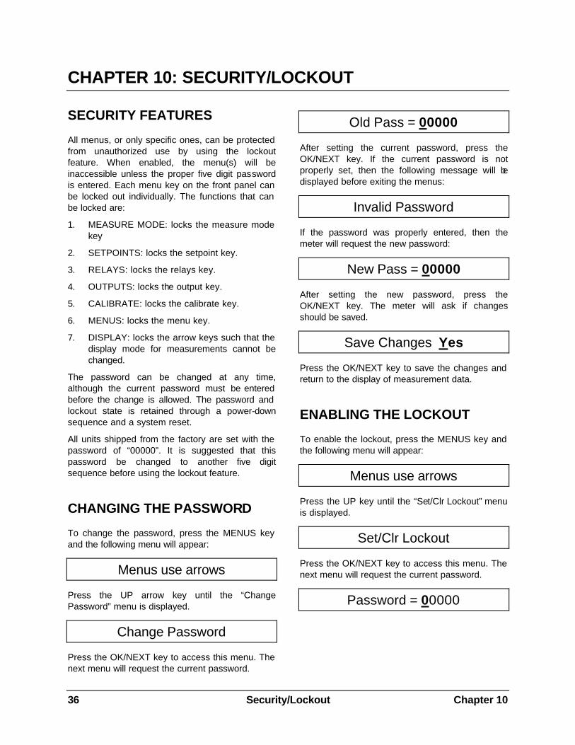
36 Security/Lockout Chapter 10
CHAPTER 10: SECURITY/LOCKOUT
SECURITY FEATURES
All menus, or only specific ones, can be protected from unauthorized use by using the lockout feature. When enabled, the menu(s) will be inaccessible unless the proper five digit password is entered. Each menu key on the front panel can be locked out individually. The functions that can be locked are:
1. MEASURE MODE: locks the measure mode key
2. SETPOINTS: locks the setpoint key.
3. RELAYS: locks the relays key.
4. OUTPUTS: locks the output key.
5. CALIBRATE: locks the calibrate key.
6. MENUS: locks the menu key.
7. DISPLAY: locks the arrow keys such that the display mode for measurements cannot be changed.
The password can be changed at any time, although the current password must be entered before the change is allowed. The password and lockout state is retained through a power-down sequence and a system reset.
All units shipped from the factory are set with the password of “00000”. It is suggested that this password be changed to another five digit sequence before using the lockout feature.
CHANGING THE PASSWORD
To change the password, press the MENUS key and the following menu will appear:
Menus use arrows
Press the UP arrow key until the “Change Password” menu is displayed.
Change Password
Press the OK/NEXT key to access this menu. The next menu will request the current password.
Old Pass = 00000
After setting the current password, press the OK/NEXT key. If the current password is not properly set, then the following message will be displayed before exiting the menus:
Invalid Password
If the password was properly entered, then the meter will request the new password:
New Pass = 00000
After setting the new password, press the OK/NEXT key. The meter will ask if changes should be saved.
Save Changes Yes
Press the OK/NEXT key to save the changes and return to the display of measurement data.
ENABLING THE LOCKOUT
To enable the lockout, press the MENUS key and the following menu will appear:
Menus use arrows
Press the UP key until the “Set/Clr Lockout” menu is displayed.
Set/Clr Lockout
Press the OK/NEXT key to access this menu. The next menu will request the current password.
Password = 00000
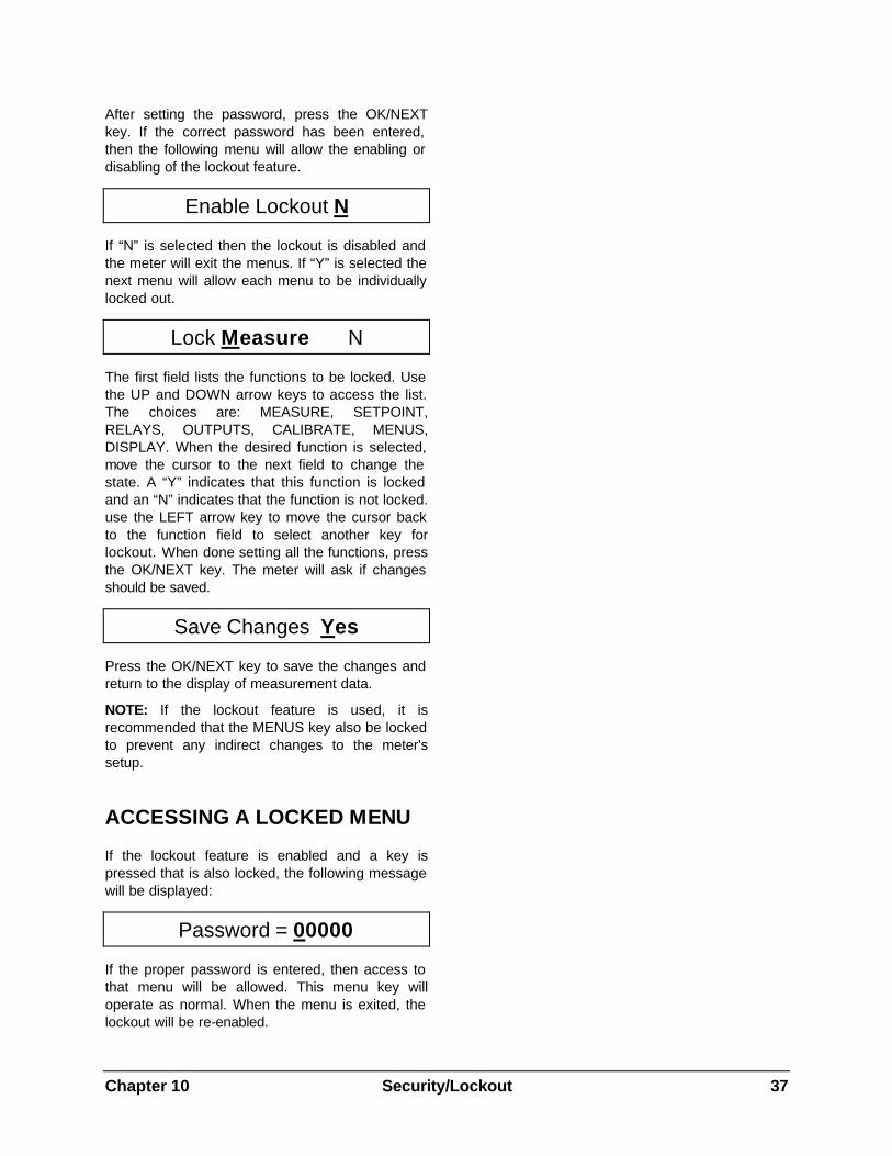
Chapter 10 Security/Lockout 37
After setting the password, press the OK/NEXT key. If the correct password has been entered, then the following menu will allow the enabling or disabling of the lockout feature.
Enable Lockout N
If “N” is selected then the lockout is disabled and the meter will exit the menus. If “Y” is selected the next menu will allow each menu to be individually locked out.
Lock Measure N
The first field lists the functions to be locked. Use the UP and DOWN arrow keys to access the list. The choices are: MEASURE, SETPOINT, RELAYS, OUTPUTS, CALIBRATE, MENUS, DISPLAY. When the desired function is selected, move the cursor to the next field to change the state. A “Y” indicates that this function is locked and an “N” indicates that the function is not locked. use the LEFT arrow key to move the cursor back to the function field to select another key for lockout. When done setting all the functions, press the OK/NEXT key. The meter will ask if changes should be saved.
Save Changes Yes
Press the OK/NEXT key to save the changes and return to the display of measurement data.
NOTE: If the lockout feature is used, it is recommended that the MENUS key also be locked to prevent any indirect changes to the meter's setup.
ACCESSING A LOCKED MENU
If the lockout feature is enabled and a key is pressed that is also locked, the following message will be displayed:
Password = 00000
If the proper password is entered, then access to that menu will be allowed. This menu key will operate as normal. When the menu is exited, the lockout will be re-enabled.
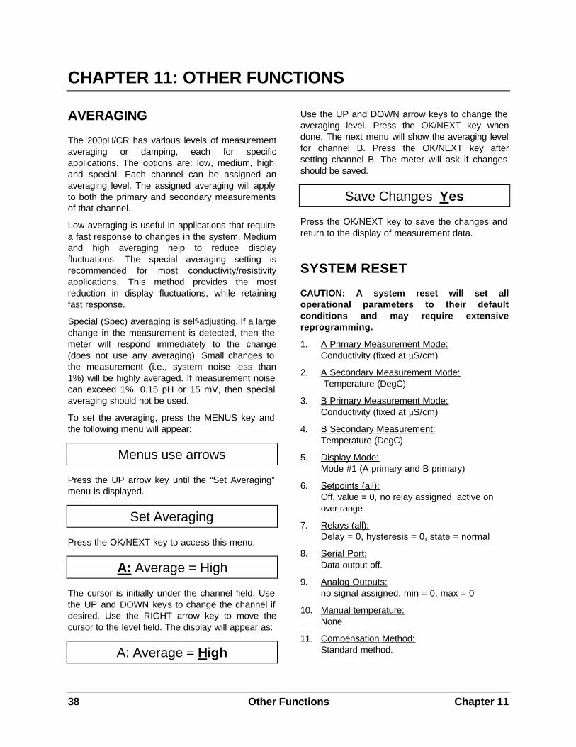
38 Other Functions Chapter 11
CHAPTER 11: OTHER FUNCTIONS
AVERAGING
The 200pH/CR has various levels of measurement averaging or damping, each for specific applications. The options are: low, medium, high and special. Each channel can be assigned an averaging level. The assigned averaging will apply to both the primary and secondary measurements of that channel.
Low averaging is useful in applications that require a fast response to changes in the system. Medium and high averaging help to reduce display fluctuations. The special averaging setting is recommended for most conductivity/resistivity applications. This method provides the most reduction in display fluctuations, while retaining fast response.
Special (Spec) averaging is self-adjusting. If a large change in the measurement is detected, then the meter will respond immediately to the change (does not use any averaging). Small changes to the measurement (i.e., system noise less than 1%) will be highly averaged. If measurement noise can exceed 1%, 0.15 pH or 15 mV, then special averaging should not be used.
To set the averaging, press the MENUS key and the following menu will appear:
Menus use arrows
Press the UP arrow key until the “Set Averaging” menu is displayed.
Set Averaging
Press the OK/NEXT key to access this menu.
A: Average = High
The cursor is initially under the channel field. Use the UP and DOWN keys to change the channel if desired. Use the RIGHT arrow key to move the cursor to the level field. The display will appear as:
A: Average = High
Use the UP and DOWN arrow keys to change the averaging level. Press the OK/NEXT key when done. The next menu will show the averaging level for channel B. Press the OK/NEXT key after setting channel B. The meter will ask if changes should be saved.
Save Changes Yes
Press the OK/NEXT key to save the changes and return to the display of measurement data.
SYSTEM RESET
CAUTION: A system reset will set all operational parameters to their default conditions and may require extensive reprogramming.
1. A Primary Measurement Mode: Conductivity (fixed at µS/cm)
2. A Secondary Measurement Mode: Temperature (DegC)
3. B Primary Measurement Mode: Conductivity (fixed at µS/cm)
4. B Secondary Measurement: Temperature (DegC)
5. Display Mode: Mode #1 (A primary and B primary)
6. Setpoints (all): Off, value = 0, no relay assigned, active on over-range
7. Relays (all): Delay = 0, hysteresis = 0, state = normal
8. Serial Port: Data output off.
9. Analog Outputs: no signal assigned, min = 0, max = 0
10. Manual temperature: None
11. Compensation Method: Standard method.
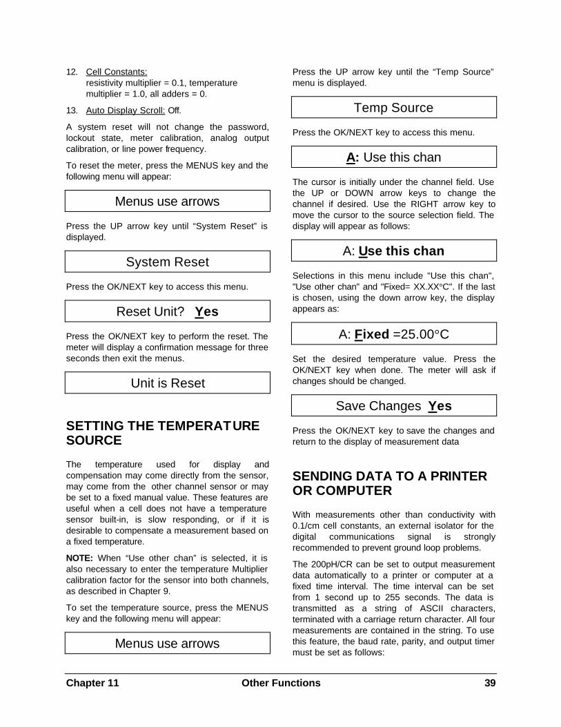
Chapter 11 Other Functions 39
12. Cell Constants: resistivity multiplier = 0.1, temperature multiplier = 1.0, all adders = 0.
13. Auto Display Scroll: Off.
A system reset will not change the password, lockout state, meter calibration, analog output calibration, or line power frequency.
To reset the meter, press the MENUS key and the following menu will appear:
Menus use arrows
Press the UP arrow key until “System Reset” is displayed.
System Reset
Press the OK/NEXT key to access this menu.
Reset Unit? Yes
Press the OK/NEXT key to perform the reset. The meter will display a confirmation message for three seconds then exit the menus.
Unit is Reset
SETTING THE TEMPERATURE SOURCE
The temperature used for display and compensation may come directly from the sensor, may come from the other channel sensor or may be set to a fixed manual value. These features are useful when a cell does not have a temperature sensor built-in, is slow responding, or if it is desirable to compensate a measurement based on a fixed temperature.
NOTE: When “Use other chan” is selected, it is also necessary to enter the temperature Multiplier calibration factor for the sensor into both channels, as described in Chapter 9.
To set the temperature source, press the MENUS key and the following menu will appear:
Menus use arrows
Press the UP arrow key until the “Temp Source” menu is displayed.
Temp Source
Press the OK/NEXT key to access this menu.
A: Use this chan
The cursor is initially under the channel field. Use the UP or DOWN arrow keys to change the channel if desired. Use the RIGHT arrow key to move the cursor to the source selection field. The display will appear as follows:
A: Use this chan
Selections in this menu include "Use this chan", "Use other chan" and "Fixed= XX.XX°C". If the last is chosen, using the down arrow key, the display appears as:
A: Fixed =25.00°C
Set the desired temperature value. Press the OK/NEXT key when done. The meter will ask if changes should be changed.
Save Changes Yes
Press the OK/NEXT key to save the changes and return to the display of measurement data
SENDING DATA TO A PRINTER OR COMPUTER
With measurements other than conductivity with 0.1/cm cell constants, an external isolator for the digital communications signal is strongly recommended to prevent ground loop problems.
The 200pH/CR can be set to output measurement data automatically to a printer or computer at a fixed time interval. The time interval can be set from 1 second up to 255 seconds. The data is transmitted as a string of ASCII characters, terminated with a carriage return character. All four measurements are contained in the string. To use this feature, the baud rate, parity, and output timer must be set as follows:
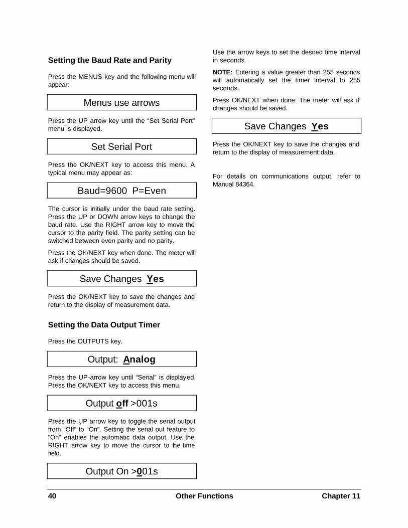
40 Other Functions Chapter 11
Setting the Baud Rate and Parity
Press the MENUS key and the following menu will appear:
Menus use arrows
Press the UP arrow key until the “Set Serial Port” menu is displayed.
Set Serial Port
Press the OK/NEXT key to access this menu. A typical menu may appear as:
Baud=9600 P=Even
The cursor is initially under the baud rate setting. Press the UP or DOWN arrow keys to change the baud rate. Use the RIGHT arrow key to move the cursor to the parity field. The parity setting can be switched between even parity and no parity.
Press the OK/NEXT key when done. The meter will ask if changes should be saved.
Save Changes Yes
Press the OK/NEXT key to save the changes and return to the display of measurement data.
Setting the Data Output Timer
Press the OUTPUTS key.
Output: Analog
Press the UP-arrow key until “Serial” is displayed. Press the OK/NEXT key to access this menu.
Output off >001s
Press the UP arrow key to toggle the serial output from “Off” to “On”. Setting the serial out feature to “On” enables the automatic data output. Use the RIGHT arrow key to move the cursor to the time field.
Output On >001s
Use the arrow keys to set the desired time interval in seconds.
NOTE: Entering a value greater than 255 seconds will automatically set the timer interval to 255 seconds.
Press OK/NEXT when done. The meter will ask if changes should be saved.
Save Changes Yes
Press the OK/NEXT key to save the changes and return to the display of measurement data.
For details on communications output, refer to Manual 84364.
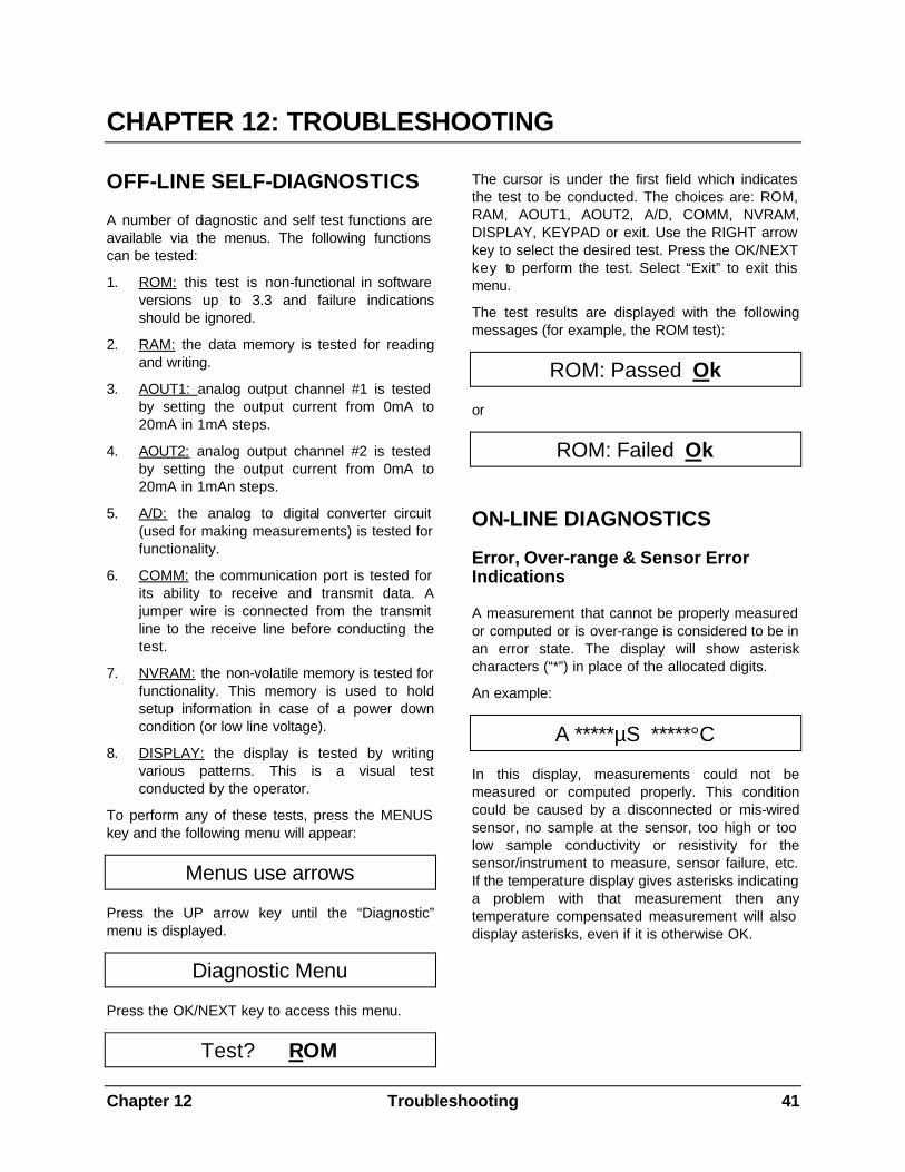
Chapter 12 Troubleshooting 41
CHAPTER 12: TROUBLESHOOTING
OFF-LINE SELF-DIAGNOSTICS
A number of diagnostic and self test functions are available via the menus. The following functions can be tested:
1. ROM: this test is non-functional in software versions up to 3.3 and failure indications should be ignored.
2. RAM: the data memory is tested for reading and writing.
3. AOUT1: analog output channel #1 is tested by setting the output current from 0mA to 20mA in 1mA steps.
4. AOUT2: analog output channel #2 is tested by setting the output current from 0mA to 20mA in 1mAn steps.
5. A/D: the analog to digital converter circuit (used for making measurements) is tested for functionality.
6. COMM: the communication port is tested for its ability to receive and transmit data. A jumper wire is connected from the transmit line to the receive line before conducting the test.
7. NVRAM: the non-volatile memory is tested for functionality. This memory is used to hold setup information in case of a power down condition (or low line voltage).
8. DISPLAY: the display is tested by writing various patterns. This is a visual test conducted by the operator.
To perform any of these tests, press the MENUS key and the following menu will appear:
Menus use arrows
Press the UP arrow key until the “Diagnostic” menu is displayed.
Diagnostic Menu
Press the OK/NEXT key to access this menu.
Test? ROM
The cursor is under the first field which indicates the test to be conducted. The choices are: ROM, RAM, AOUT1, AOUT2, A/D, COMM, NVRAM, DISPLAY, KEYPAD or exit. Use the RIGHT arrow key to select the desired test. Press the OK/NEXT key to perform the test. Select “Exit” to exit this menu.
The test results are displayed with the following messages (for example, the ROM test):
ROM: Passed Ok
or
ROM: Failed Ok
ON-LINE DIAGNOSTICS
Error, Over-range & Sensor Error Indications
A measurement that cannot be properly measured or computed or is over-range is considered to be in an error state. The display will show asterisk characters (“*”) in place of the allocated digits.
An example:
A *****µS *****°C
In this display, measurements could not be measured or computed properly. This condition could be caused by a disconnected or mis-wired sensor, no sample at the sensor, too high or too low sample conductivity or resistivity for the sensor/instrument to measure, sensor failure, etc. If the temperature display gives asterisks indicating a problem with that measurement then any temperature compensated measurement will also display asterisks, even if it is otherwise OK.
42 Troubleshooting Chapter 12
“Check Setup” Message
The 200pH/CR constantly checks the condition of the setup data (setpoints, compensation methods, etc.). If the meter detects an unauthorized change in this data (i.e., corrupted data) then a message will be displayed every few seconds as follows:
Check Setup
This message can be cleared by entering and exiting any menu.
TROUBLESHOOTING
Problem Possible Cause
1. Display is blank • no power to unit • blown fuse • loose display cable • display contrast potentiometer needs adjustment • display cable improperly connected • circuit board failure
2. Wrong readings • sensor improperly installed • incorrect measurement prefix entered • incorrect cell constant entered • meter improperly calibrated • temperature compensation is incorrectly set or disabled • sensor patch cord is defective • defective sensor • circuit board failure
3. Keypad not functioning • keypad cable connector loose or broken • defective keypad
4. Negative readings in %rejection •% rejection is calculated on the wrong channel
5. Readings fluctuate too much • wrong line power frequency selected • cells and/or cables installed too close to equipment that gen- erates high levels of electrical noise
6. Data not sent out to serial port • serial port wiring is wrong • wrong baud rate and/or parity • automatic data output not enabled • data output timer set too high
RECOVERY PROCEDURE
If the meter is unable to make valid measurements, then the following procedure may help to resolve the problem.
1. Check sensor patch cord wiring. Look for loose wires at the terminal block or incorrect wiring.
2. Perform a system reset as outlined in SYSTEM RESET in Chapter 11.
3. Re-enter the cell constants as shown in ENTER/EDITING CELL CONSTANTS in Chapter 9. Set the desired measurement mode and prefix as shown in SELECTING A MEASUREMENT TYPE in Chapter 4.
4. Re-calibrate the meter as outlined in Chapter 8.
5. Check that the proper compensation method is selected.
Chapter 13 Service 43
CHAPTER 13: SERVICE
FUSE REPLACEMENT
The 200pH/CR is protected from accidental voltage overloading, short circuits, and related damage by a 1/8 amp time-delayed fuse (for 115 VAC units only). The 230 VAC unit uses a 1/16 amp time-delayed fuse. The fuse is located on the printed circuit board (PCB) inside of the case.
WARNING: FOR CONTINUED PROTECTION AGAINST RISK OF FIRE, REPLACE ONLY WITH FUSE OF THE SPECIFIED TYPE AND CURRENT RATING.
To replace the fuse:
1. Disconnect all power to the 200pH/CR unit before proceeding.
2. Remove the two screws from the center of the rear panel.
3. Slowly pull the rear panel assembly out of the unit, no more than 1”.
4. Disconnect the two ribbon cables connecting the case to the PCB.
5. The fuse is located near the transformer. Remove the old fuse and replace it with one with the same rating as indicated above.
6. Position the PCB near the case and connect the two cables to the PCB. Make sure each cable is properly seated and oriented.
7. Gently push the rear panel assembly back into the case. Make sure the four mounted posts align with the holes in the assembly.
8. When the assembly is properly seated, re-install the two mounting screws.
9. Reconnect power to the meter.
REDUCING 200PH/CR PATCH CORD LENGTH
200pH/CR patch cords are available in a variety of standard lengths. Occasionally it is necessary to reduce standard cord lengths to accommodate system design. The following procedure outlines how to terminate the end of the cable to assure accurate system operation. The 200pH/CR patch cords include two (2) drain (bare) wires. It is essential that these wires never make contact with each other. Place insulating tubing over these wires.
CAUTION: If the wires are touching, it will cause the readings to be inaccurate. Be sure that the wires never make contact with each other.
Tools required:
Cable cutters, wire strippers, insulating tubing, soldering iron & solder, wire markers (optional).
Procedure:
1. Measure the cable from the end connector to the desired length and cut.
2. Strip outer jacket and shield 4 inches from the end.
3. Cut at the jacket the orange, yellow and all white wires that are outside the inner shield. DO NOT CUT the drain (bare) or the wires enclosed inside the inner shield.
4. Strip the inner shield all the way to the jacket.
5. Strip all leads 1/4 inch and tin the inner shield.
6. Slide clear insulating tubing over the inner drain (bare) wire. Tuck the insulating tubing under the jacket. THIS WIRE MUST NEVER TOUCH THE OUTER SHIELD OR OUTER DRAIN WIRE.
7. Place wire markers on leads if desired.
8. Wire the cable to the 200pH/CR as indicated. See Figure 14.8 and Table 2.5.
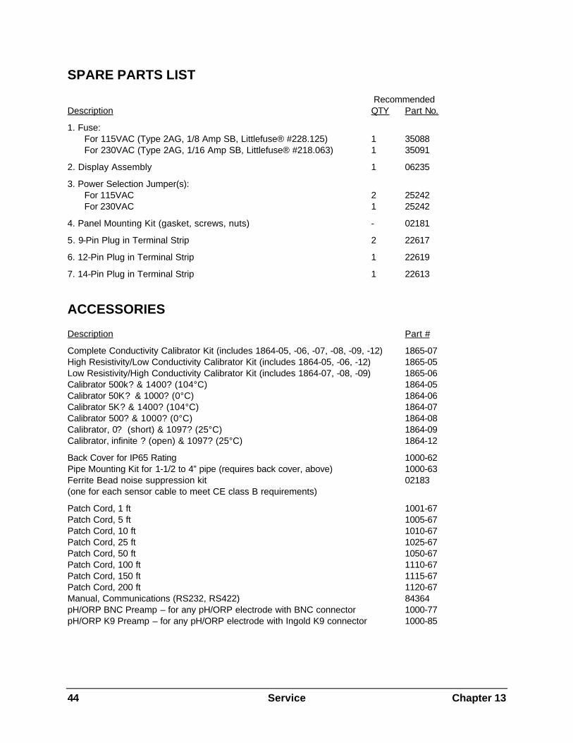
44 Service Chapter 13
SPARE PARTS LIST
Recommended Description QTY Part No.
1. Fuse: For 115VAC (Type 2AG, 1/8 Amp SB, Littlefuse® #228.125) 1 35088 For 230VAC (Type 2AG, 1/16 Amp SB, Littlefuse® #218.063) 1 35091
2. Display Assembly 1 06235
3. Power Selection Jumper(s): For 115VAC 2 25242 For 230VAC 1 25242
4. Panel Mounting Kit (gasket, screws, nuts) - 02181
5. 9-Pin Plug in Terminal Strip 2 22617
6. 12-Pin Plug in Terminal Strip 1 22619
7. 14-Pin Plug in Terminal Strip 1 22613
ACCESSORIES
Description Part #
Complete Conductivity Calibrator Kit (includes 1864-05, -06, -07, -08, -09, -12) 1865-07 High Resistivity/Low Conductivity Calibrator Kit (includes 1864-05, -06, -12) 1865-05 Low Resistivity/High Conductivity Calibrator Kit (includes 1864-07, -08, -09) 1865-06 Calibrator 500k? & 1400? (104°C) 1864-05 Calibrator 50K? & 1000? (0°C) 1864-06 Calibrator 5K? & 1400? (104°C) 1864-07 Calibrator 500? & 1000? (0°C) 1864-08 Calibrator, 0? (short) & 1097? (25°C) 1864-09 Calibrator, infinite ? (open) & 1097? (25°C) 1864-12
Back Cover for IP65 Rating 1000-62 Pipe Mounting Kit for 1-1/2 to 4” pipe (requires back cover, above) 1000-63 Ferrite Bead noise suppression kit 02183 (one for each sensor cable to meet CE class B requirements)
Patch Cord, 1 ft 1001-67 Patch Cord, 5 ft 1005-67 Patch Cord, 10 ft 1010-67 Patch Cord, 25 ft 1025-67 Patch Cord, 50 ft 1050-67 Patch Cord, 100 ft 1110-67 Patch Cord, 150 ft 1115-67 Patch Cord, 200 ft 1120-67 Manual, Communications (RS232, RS422) 84364 pH/ORP BNC Preamp – for any pH/ORP electrode with BNC connector 1000-77 pH/ORP K9 Preamp – for any pH/ORP electrode with Ingold K9 connector 1000-85
Chapter 14 Technical Illustrations 45
CHAPTER 14: TECHNICAL ILLUSTRATIONS
MENU TREES
OVERALL DIMENSIONS
PANEL CUTOUT
EXPLODED ASSEMBLY
PIPE MOUNTING
SEALED IP65 REAR ASSEMBLY
PRINTED CIRCUIT BOARD LAYOUT
REAR PANEL WIRING & PATCH CORDS
CALIBRATORS
METER CALIBRATION USING DECADE BOX AND VOLTAGE SOURCE
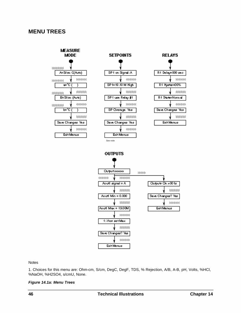
46 Technical Illustrations Chapter 14
MENU TREES
Notes
1. Choices for this menu are: Ohm-cm, S/cm, DegC, DegF, TDS, % Rejection, A/B, A-B, pH, Volts, %HCl, %NaOH, %H2SO4, s/cmU, None.
Figure 14.1a: Menu Trees
See note
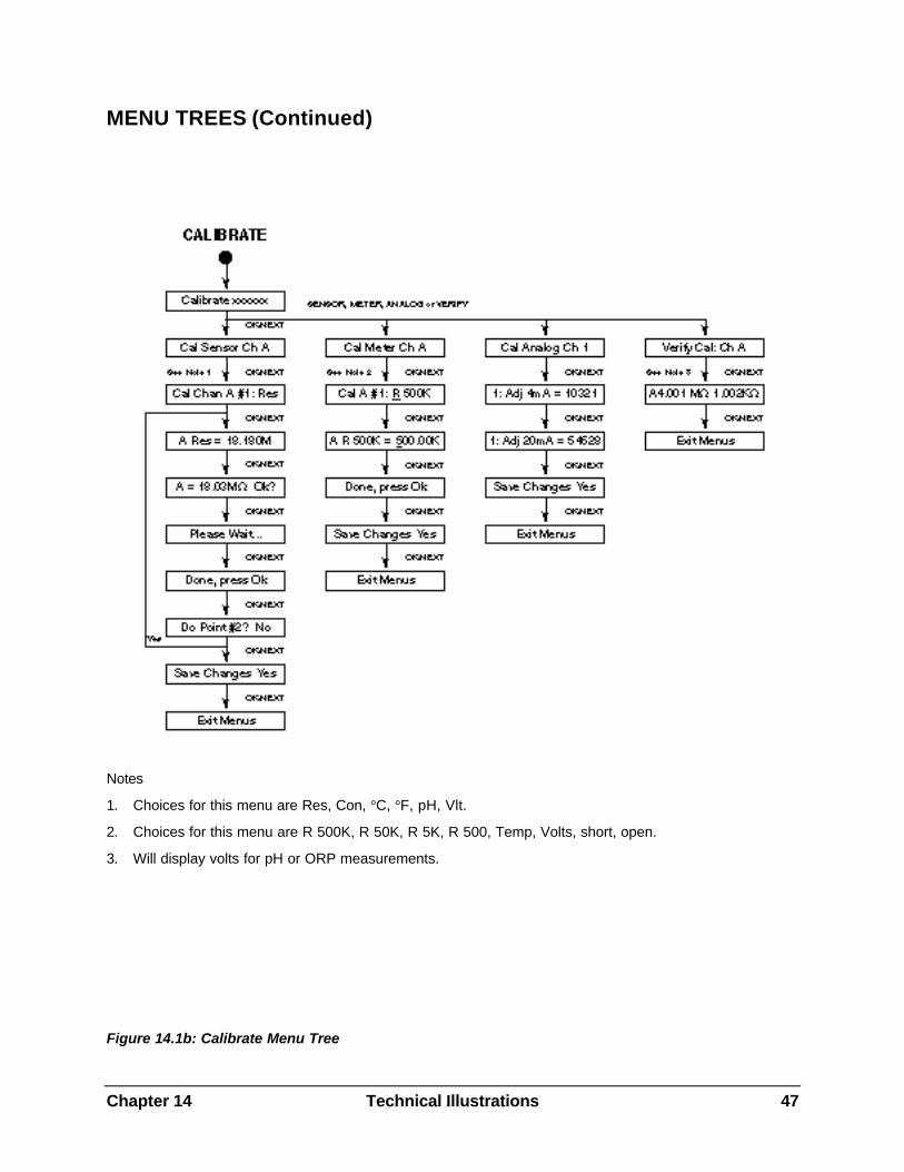
Chapter 14 Technical Illustrations 47
MENU TREES (Continued)
Notes
1. Choices for this menu are Res, Con, °C, °F, pH, Vlt.
2. Choices for this menu are R 500K, R 50K, R 5K, R 500, Temp, Volts, short, open.
3. Will display volts for pH or ORP measurements.
Figure 14.1b: Calibrate Menu Tree
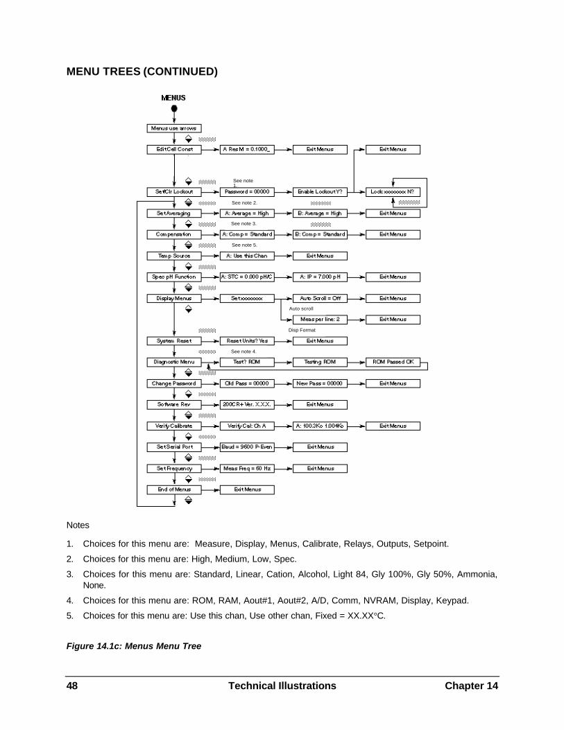
48 Technical Illustrations Chapter 14
MENU TREES (CONTINUED)
Notes
1. Choices for this menu are: Measure, Display, Menus, Calibrate, Relays, Outputs, Setpoint.
2. Choices for this menu are: High, Medium, Low, Spec.
3. Choices for this menu are: Standard, Linear, Cation, Alcohol, Light 84, Gly 100%, Gly 50%, Ammonia, None.
4. Choices for this menu are: ROM, RAM, Aout#1, Aout#2, A/D, Comm, NVRAM, Display, Keypad.
5. Choices for this menu are: Use this chan, Use other chan, Fixed = XX.XX°C.
Figure 14.1c: Menus Menu Tree
See note 1.
See note 2.
See note 3.
See note 5.
See note 4.
Auto scroll
Disp Format
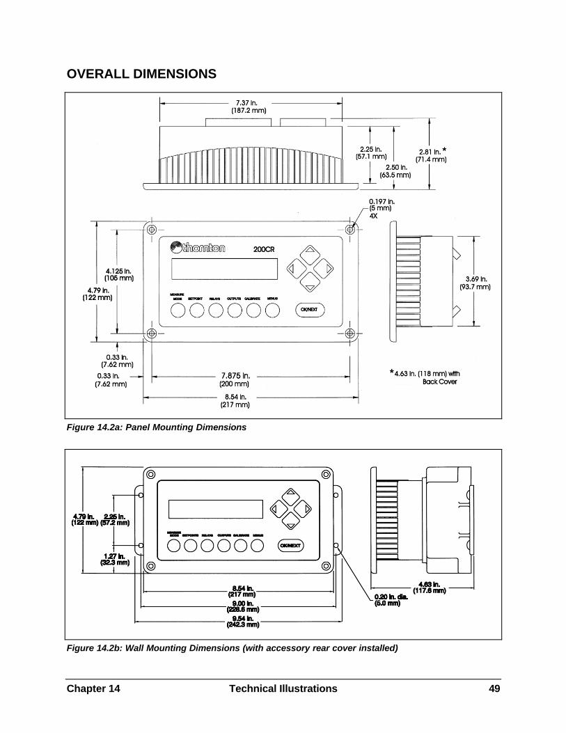
Chapter 14 Technical Illustrations 49
OVERALL DIMENSIONS
Figure 14.2a: Panel Mounting Dimensions
Figure 14.2b: Wall Mounting Dimensions (with accessory rear cover installed)
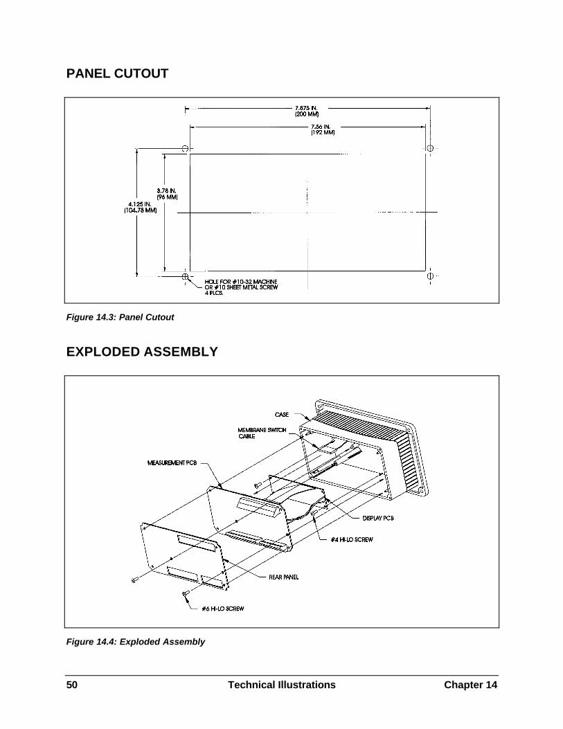
50 Technical Illustrations Chapter 14
PANEL CUTOUT
Figure 14.3: Panel Cutout
EXPLODED ASSEMBLY
Figure 14.4: Exploded Assembly
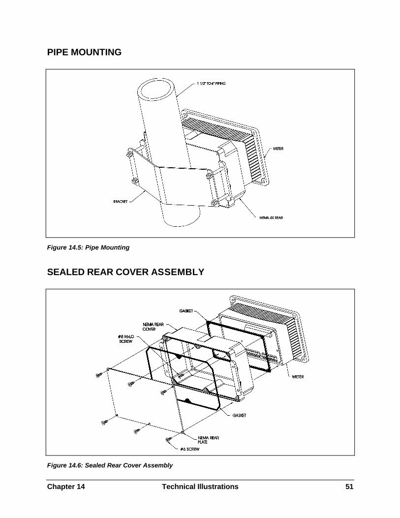
Chapter 14 Technical Illustrations 51
PIPE MOUNTING
Figure 14.5: Pipe Mounting
SEALED REAR COVER ASSEMBLY
Figure 14.6: Sealed Rear Cover Assembly
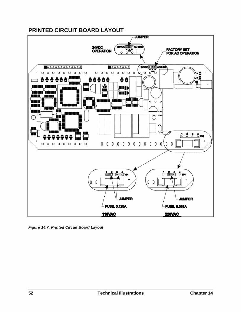
52 Technical Illustrations Chapter 14
PRINTED CIRCUIT BOARD LAYOUT
Figure 14.7: Printed Circuit Board Layout
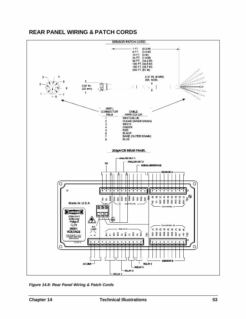
Chapter 14 Technical Illustrations 53
REAR PANEL WIRING & PATCH CORDS
Figure 14.8: Rear Panel Wiring & Patch Cords
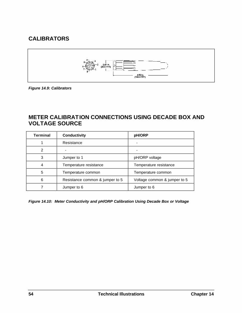
54 Technical Illustrations Chapter 14
CALIBRATORS
Figure 14.9: Calibrators
METER CALIBRATION CONNECTIONS USING DECADE BOX AND VOLTAGE SOURCE
Terminal Conductivity pH/ORP
1 Resistance -
2 - -
3 Jumper to 1 pH/ORP voltage
4 Temperature resistance Temperature resistance
5 Temperature common Temperature common
6 Resistance common & jumper to 5 Voltage common & jumper to 5
7 Jumper to 6 Jumper to 6
Figure 14.10: Meter Conductivity and pH/ORP Calibration Using Decade Box or Voltage
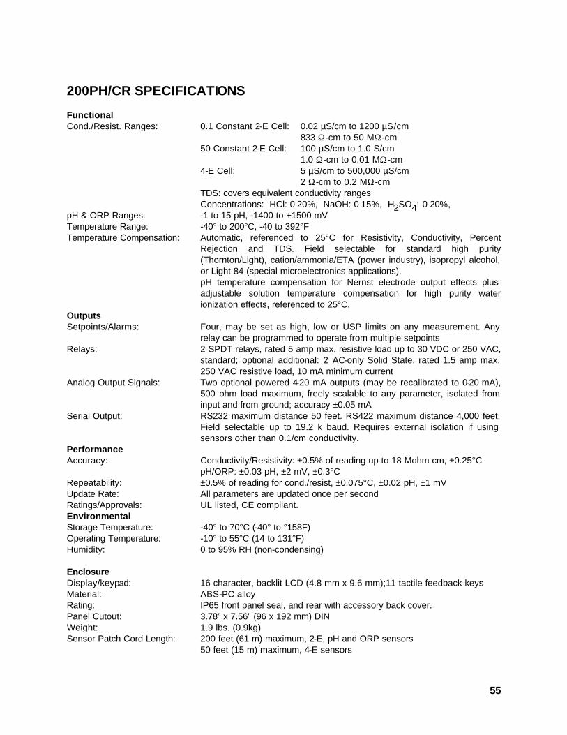
55
200PH/CR SPECIFICATIONS
Functional Cond./Resist. Ranges: 0.1 Constant 2-E Cell: 0.02 µS/cm to 1200 µS/cm 833 Ω-cm to 50 MΩ-cm 50 Constant 2-E Cell: 100 µS/cm to 1.0 S/cm 1.0 Ω-cm to 0.01 MΩ-cm 4-E Cell: 5 µS/cm to 500,000 µS/cm 2 Ω-cm to 0.2 MΩ-cm TDS: covers equivalent conductivity ranges Concentrations: HCl: 0-20%, NaOH: 0-15%, H2SO4: 0-20%, pH & ORP Ranges: -1 to 15 pH, -1400 to +1500 mV Temperature Range: -40° to 200°C, -40 to 392°F Temperature Compensation: Automatic, referenced to 25°C for Resistivity, Conductivity, Percent
Rejection and TDS. Field selectable for standard high purity (Thornton/Light), cation/ammonia/ETA (power industry), isopropyl alcohol, or Light 84 (special microelectronics applications).
pH temperature compensation for Nernst electrode output effects plus adjustable solution temperature compensation for high purity water ionization effects, referenced to 25°C.
Outputs Setpoints/Alarms: Four, may be set as high, low or USP limits on any measurement. Any
relay can be programmed to operate from multiple setpoints Relays: 2 SPDT relays, rated 5 amp max. resistive load up to 30 VDC or 250 VAC,
standard; optional additional: 2 AC-only Solid State, rated 1.5 amp max, 250 VAC resistive load, 10 mA minimum current
Analog Output Signals: Two optional powered 4-20 mA outputs (may be recalibrated to 0-20 mA), 500 ohm load maximum, freely scalable to any parameter, isolated from input and from ground; accuracy ±0.05 mA
Serial Output: RS232 maximum distance 50 feet. RS422 maximum distance 4,000 feet. Field selectable up to 19.2 k baud. Requires external isolation if using sensors other than 0.1/cm conductivity.
Performance Accuracy: Conductivity/Resistivity: ±0.5% of reading up to 18 Mohm-cm, ±0.25°C pH/ORP: ±0.03 pH, ±2 mV, ±0.3°C Repeatability: ±0.5% of reading for cond./resist, ±0.075°C, ±0.02 pH, ±1 mV Update Rate: All parameters are updated once per second Ratings/Approvals: UL listed, CE compliant. Environmental Storage Temperature: -40° to 70°C (-40° to °158F) Operating Temperature: -10° to 55°C (14 to 131°F) Humidity: 0 to 95% RH (non-condensing) Enclosure Display/keypad: 16 character, backlit LCD (4.8 mm x 9.6 mm);11 tactile feedback keys Material: ABS-PC alloy Rating: IP65 front panel seal, and rear with accessory back cover. Panel Cutout: 3.78” x 7.56” (96 x 192 mm) DIN Weight: 1.9 lbs. (0.9kg) Sensor Patch Cord Length: 200 feet (61 m) maximum, 2-E, pH and ORP sensors 50 feet (15 m) maximum, 4-E sensors
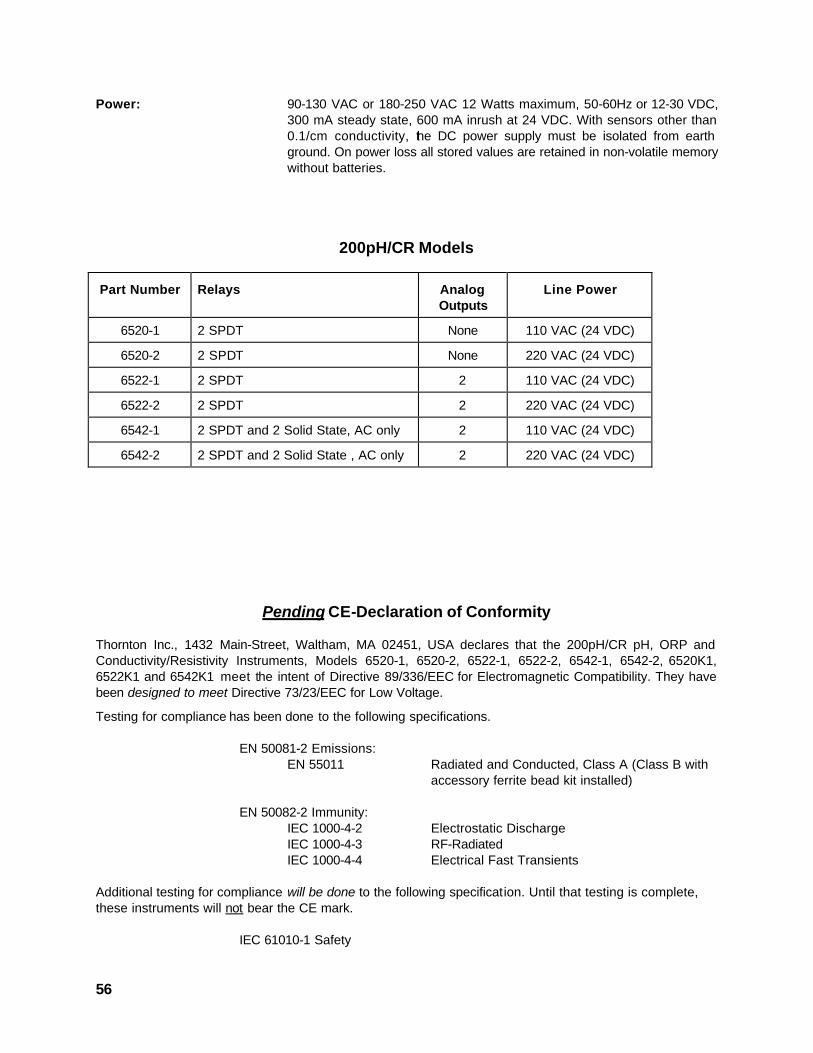
56
Power: 90-130 VAC or 180-250 VAC 12 Watts maximum, 50-60Hz or 12-30 VDC, 300 mA steady state, 600 mA inrush at 24 VDC. With sensors other than 0.1/cm conductivity, the DC power supply must be isolated from earth ground. On power loss all stored values are retained in non-volatile memory without batteries.
200pH/CR Models
Part Number Relays Analog Outputs
Line Power
6520-1 2 SPDT None 110 VAC (24 VDC)
6520-2 2 SPDT None 220 VAC (24 VDC)
6522-1 2 SPDT 2 110 VAC (24 VDC)
6522-2 2 SPDT 2 220 VAC (24 VDC)
6542-1 2 SPDT and 2 Solid State, AC only 2 110 VAC (24 VDC)
6542-2 2 SPDT and 2 Solid State , AC only 2 220 VAC (24 VDC)
Pending CE-Declaration of Conformity
Thornton Inc., 1432 Main-Street, Waltham, MA 02451, USA declares that the 200pH/CR pH, ORP and Conductivity/Resistivity Instruments, Models 6520-1, 6520-2, 6522-1, 6522-2, 6542-1, 6542-2, 6520K1, 6522K1 and 6542K1 meet the intent of Directive 89/336/EEC for Electromagnetic Compatibility. They have been designed to meet Directive 73/23/EEC for Low Voltage.
Testing for compliance has been done to the following specifications. EN 50081-2 Emissions:
EN 55011 Radiated and Conducted, Class A (Class B with accessory ferrite bead kit installed)
EN 50082-2 Immunity: IEC 1000-4-2 Electrostatic Discharge IEC 1000-4-3 RF-Radiated IEC 1000-4-4 Electrical Fast Transients Additional testing for compliance will be done to the following specification. Until that testing is complete, these instruments will not bear the CE mark. IEC 61010-1 Safety
57
UL Listing
Thornton Inc., 1432 Main Street, Waltham, MA 02451, USA has obtained Underwriters Laboratories’ Listing for 200pH/CR pH, ORP and Conductivity/Resistivity Instruments. They bear the UL Listed mark signifying that the products have been evaluated to the applicable UL standards for electrical process control equipment, UL3121-1.
WARRANTY
Thornton Inc. warrants products it manufactures against defects in materials or workmanship for one year from start-up or 18 months from the date of shipment from Thornton, whichever is sooner. Warranties do not apply to limited life components such as batteries. Some non-Thornton manufactured resale items may have shorter warranties than one year. Thornton honors only the warranty period of the original manufacturer. Catalog descriptions, although accurate, should not be taken as a guarantee or warranty. Thornton’s obligation under the warranty shall be to repair at its facility or replace any products which Thornton finds to be defective. Items returned for warranty must be properly packaged, shipped prepaid and insured, and must be accompanied by the Return Authorization Number described below.
Returned Goods: Please contact us for a Return Authorization Number before any item is returned. Items returned for credit or exchange must be in salable condition. Items returned after 30 days from date of invoice, will be subject to a 10% rehandling charge.
Note: Substitution or modification of cables voids all warranties.
THE ABOVE WARRANTY IS THE ONLY WARRANTY MADE BY THORNTON INC. AND IS IN LIEU OF ALL OTHER WARRANTIES, EXPRESS OR IMPLIED, INCLUDING, WITHOUT LIMITATION, IMPLIED WARRANTIES OF MERCHANTABILITY AND FITNESS FOR A PARTICULAR PURPOSE.

Thornton Inc. 1432 Main Street Waltham, MA 02451-1623 (781) 839-6400
Smartline: 800-642-4418 Faxline: 781-890-5507
Email: [email protected]
Part No. 84383 Rev. B 12/00


![Sizes Payload Compensation path XY up to 20 kg - Comoso · Compensation path XY ... Material CR CR CR CR NBR CR CR CR CR CR CR NBR NBR NBR NBR NBR ... Bending [Nm/rad] 474 552 1025](https://img.pdfslide.net/doc/110x75/5af1b3557f8b9ac57a903b0d/sizes-payload-compensation-path-xy-up-to-20-kg-path-xy-material-cr-cr-cr-cr.jpg)