Embed Size (px)
Citation preview

201-MHz NCRF Cavity 201-MHz NCRF Cavity ProgramProgram
Derun LiDerun LiCenter for Beam PhysicsCenter for Beam Physics
Lawrence Berkeley National LaboratoryLawrence Berkeley National Laboratory
MUTAC Review at FermilabMUTAC Review at FermilabMarch 16, 2006March 16, 2006
CollaboratorsCollaboratorsM. Dickson, R. MacGill, J. Staples, S. Virostek, M. Zisman
Lawrence Berkeley National LaboratoryA. Bross, A. Moretti, B. Norris, Z. QianFermi National Accelerator Laboratory
J. NoremArgonne National LaboratoryR. Rimmer, L. Phillips, G. WuJefferson National Laboratory
Y. TorunIllinois Institute of Technology
D. SummersUniversity of Mississippi
W. Lau, S. YangOxford University, UK

OutlineOutline• Introduction• 201 MHz Cavity Progress
– Cavity design and fabrication• Cleaning, vacuum and assembly • Shipping
– Installation at MTA, FNAL• Installation: vacuum, RF couplers and probes, power
transmission lines, baking system, …• Low power microwave measurements
– Progress on curved Be windows • 21-cm (radius) curved Be windows for 201 MHz cavity• Asymmetric heating of the curved windows• Transient studies: pulse heating and to steady state
– Preliminary tests of the cavity
• Summary

IntroductionIntroduction
– High gradient RF cavities to compensate for lost longitudinal energy– Strong magnetic field to confine muon beams– Lose energy in LH absorbersGoal:– Development of NC 201-MHz cavity that can operate at ~ 16 MV/m under a few Tesla solenoidal B fields
Ionization Cooling LH Absorbers
RF Cavities
dxdE
dxdE
dxdE
Designing, engineering, fabricating, conditioning and operating a cavity at 16 MV/m with B is a challenging
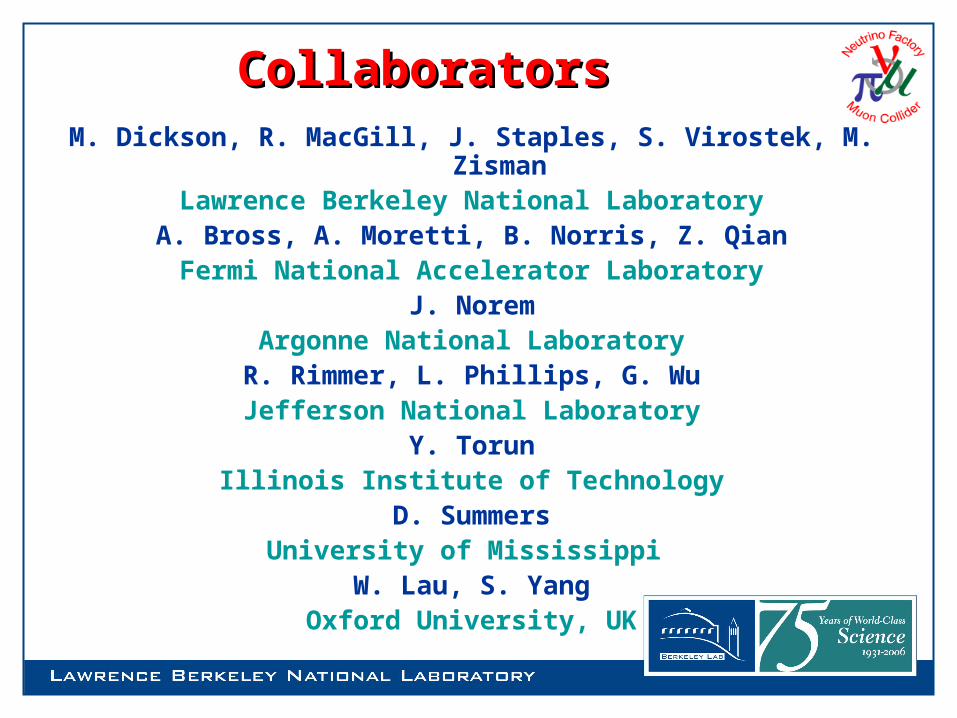
Introduction (Cont’d)Introduction (Cont’d)NCRF R&D ProgramsNCRF R&D ProgramsDevelop highest possible NCRF accelerating structure to meet the Develop highest possible NCRF accelerating structure to meet the
requirements for NF or MCrequirements for NF or MC • Prototype of 201 MHz cavity
– Completed cavity design and fabrication– Cavity installation at MTA in Sept. 2005
• Assembly and vacuum • RF power plumbing
– RF conditioning started in late Feb. 2006• Experimental studies at 805 MHz with and without external
magnetic fields up to 5-Tesla (2.5 Tesla for MICE)– Completed 5-cell cavity with open iris test at Lab G – Designed, fabricated and tested pillbox-like cavity with demountable
windows at Lab G and moved and resumed recently at MTA, FNAL– Tests with two curved Be windows
• Reached 32 MV/m easily without external magnetic field• More tests are in progress with magnetic fields versus achievable gradient
– Button test

Cavity Status at Last MUTACCavity Status at Last MUTACWhere we were at last MUTAC in Berkeley (Apr-2005)
Welding of cooling tube to cavity Extruding of four ports and vacuum leak tight Placed purchase order of curved Be windows
Work needs to be done at the time: Cavity interior buffing Chemical cleaning and high pressure water rinse of the cavity interior Surface cleaning + electro-polishing (EP) High power RF conditioning of RF couplers with windows Low power microwave measurements of the cavity with windows:
Frequency Quality factor Q Couplings
RF coupler measurement and tuning Packing and shipping to MTA, FNAL
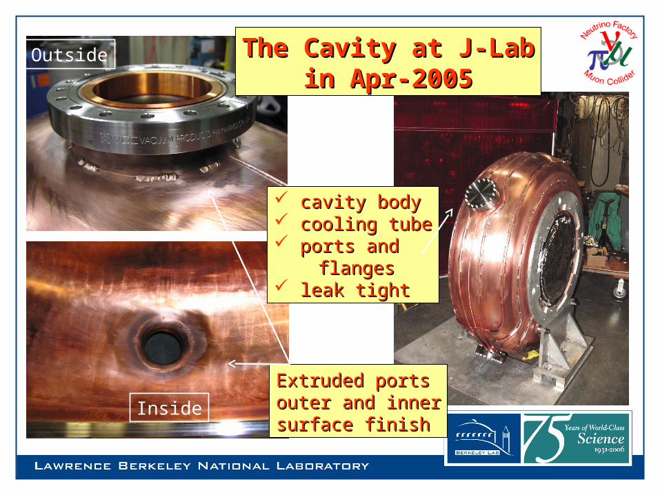
Extruded portsExtruded portsouter and innerouter and innersurface finishsurface finish
Outside
Inside
cavity bodycavity body cooling tubecooling tube ports and ports and flangesflanges leak tightleak tight
The Cavity at J-LabThe Cavity at J-Labin Apr-2005in Apr-2005
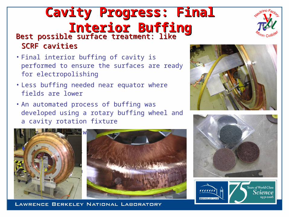
Best possible surface treatment: like SCRF Best possible surface treatment: like SCRF cavitiescavities
• Final interior buffing of cavity is performed to ensure the surfaces are ready for electropolishing
• Less buffing needed near equator where fields are lower
• An automated process of buffing was developed using a rotary buffing wheel and a cavity rotation fixture
• Some local hand work required to clean up some areas
• A series of pads with graduated coarseness was used
• Goal was scratch depth shallow enough for EP removal
Cavity Progress: Final Interior BuffingCavity Progress: Final Interior Buffing
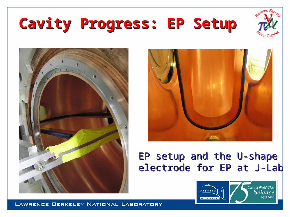
Cavity Progress: EP SetupCavity Progress: EP Setup
EP setup and the U-shape EP setup and the U-shape electrode for EP at J-Labelectrode for EP at J-Lab
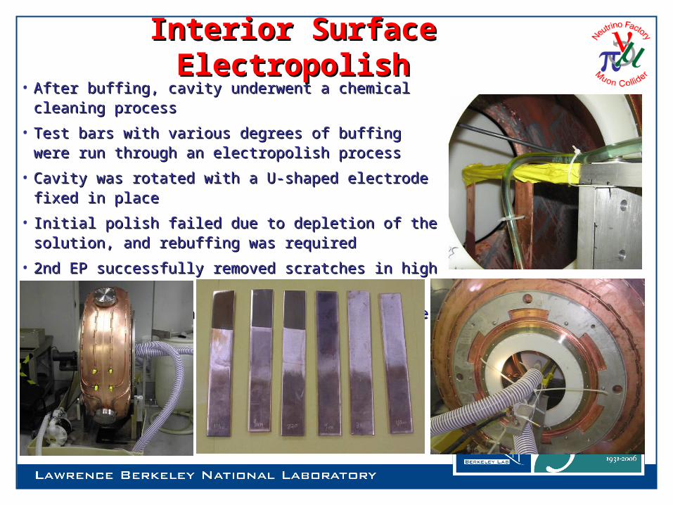
• After buffing, cavity underwent a chemical cleaning After buffing, cavity underwent a chemical cleaning processprocess
• Test bars with various degrees of buffing were run Test bars with various degrees of buffing were run through an electropolish processthrough an electropolish process
• Cavity was rotated with a U-shaped electrode fixed in Cavity was rotated with a U-shaped electrode fixed in placeplace
• Initial polish failed due to depletion of the solution, Initial polish failed due to depletion of the solution, and rebuffing was required and rebuffing was required
• 2nd EP successfully removed scratches in high field 2nd EP successfully removed scratches in high field regionsregions
• Final process is a high pressure water rinse of cavity Final process is a high pressure water rinse of cavity surfacesurface
Interior Surface ElectropolishInterior Surface Electropolish

• Coupling loops were fabricated using standard copper Coupling loops were fabricated using standard copper co-axco-ax
• Most coupler parts were joined by torch brazing – Most coupler parts were joined by torch brazing – vacuum leaks were found in two of the outer vacuum leaks were found in two of the outer conductor jointsconductor joints
• Coupling loop contains an integrated cooling tubeCoupling loop contains an integrated cooling tube
• The coupler was designed to mate with an SNS style The coupler was designed to mate with an SNS style RF window manufactured by ToshibaRF window manufactured by Toshiba
• High power conditioning performed at SNS (ORNL)High power conditioning performed at SNS (ORNL)
Cavity RF Couplers and AssemblyCavity RF Couplers and Assembly
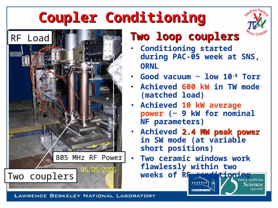
Coupler ConditioningCoupler ConditioningTwo loop couplersTwo loop couplers• Conditioning started during
PAC-05 week at SNS, ORNL • Good vacuum ~ low 10-8 Torr• Achieved 600 kW in TW mode
(matched load)• Achieved 10 kW average power
(~ 9 kW for nominal NF parameters)
• Achieved 2.4 MW peak power2.4 MW peak power in SW mode (at variable short positions)
• Two ceramic windows work flawlessly within two weeks of RF conditioning
805 MHz RF Power
Two couplers
RF Load
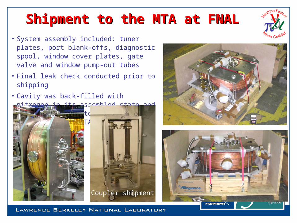
Shipment to the MTA at FNALShipment to the MTA at FNAL• System assembly included: tuner plates,
port blank-offs, diagnostic spool, window cover plates, gate valve and window pump-out tubes
• Final leak check conducted prior to shipping
• Cavity was back-filled with nitrogen in its assembled state and packaged in a custom made crate for shipping to the MTA
Coupler shipment

Final Assembly & Measurement at MTAFinal Assembly & Measurement at MTA
• Cavity assembly was mounted on the support and couplers were installed in a portable clean room
• Dummy copper windows (flat) are used initially
• Couplers were set and frequency was measured
• Bakeout system hardware was installed
• System is leak tight
View port with RF probes
RF loop couplers
End plate withdiagnostic ports

Low Power Measurements at MTALow Power Measurements at MTAf = 199.578 MHz
Q0 = 49,000 ~ 51,000 (better than 90% of the design value)
Two couplers balanced coupling adjustments
S11 Measurement

Tuner MeasurementsTuner Measurements• Mechanical tuning plates at four
locations
• Dial indicators to measure displacement between Al plates
• Tuning measurement in air
– Equivalent to MICE cavity under vacuum
• Adjusted up to 2-mm with 8 steps of 0.25-mm each
• Measured tuner sensitivity – ~ 78 kHz/mm
• Calculated tuner sensitivity– 115 kHz/mm– Disagreements are due to
deflection of the Al platesDial indicators

Curved Be WindowsCurved Be Windows• Two windows available now (LBNL)
– 42-cm in diameter and 0.38-mm in thickness– Good braze (between the two annular copper frames and the
thin beryllium foil) – Achieved the designed window profile – Thin Ti-N coatings on both sides
• Ready for HP tests
42-cm
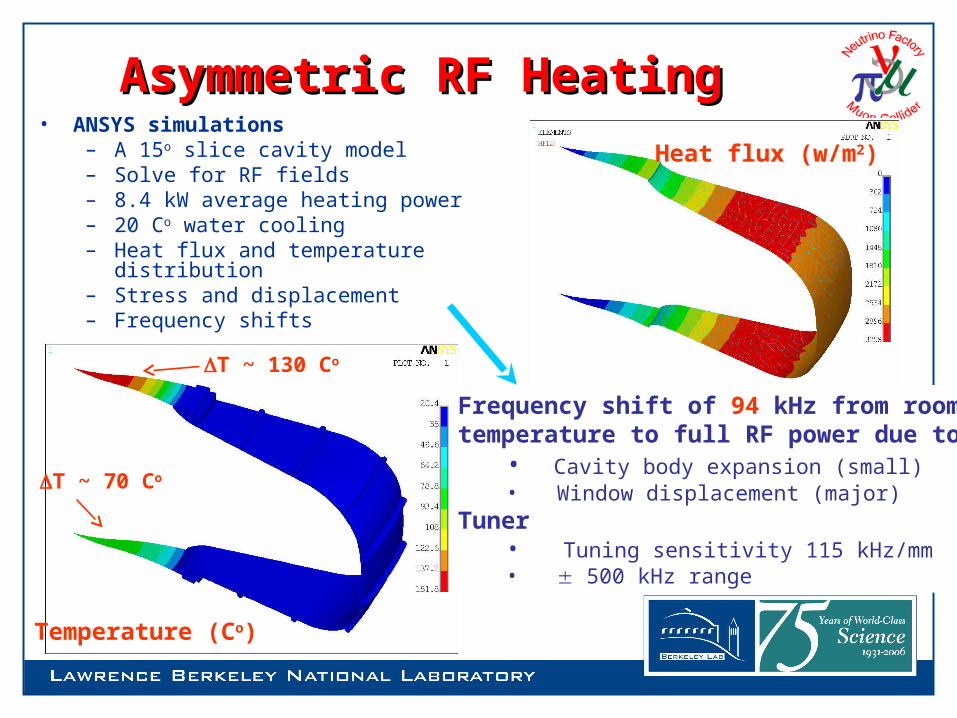
Asymmetric RF HeatingAsymmetric RF Heating• ANSYS simulations
– A 15o slice cavity model– Solve for RF fields– 8.4 kW average heating power– 20 Co water cooling– Heat flux and temperature distribution– Stress and displacement– Frequency shifts
Heat flux (w/m2)
Temperature (Co)
T ~ 130 Co
T ~ 70 Co
Frequency shift of 94 kHz from roomtemperature to full RF power due to
• Cavity body expansion (small)• Window displacement (major)
Tuner• Tuning sensitivity 115 kHz/mm• 500 kHz range
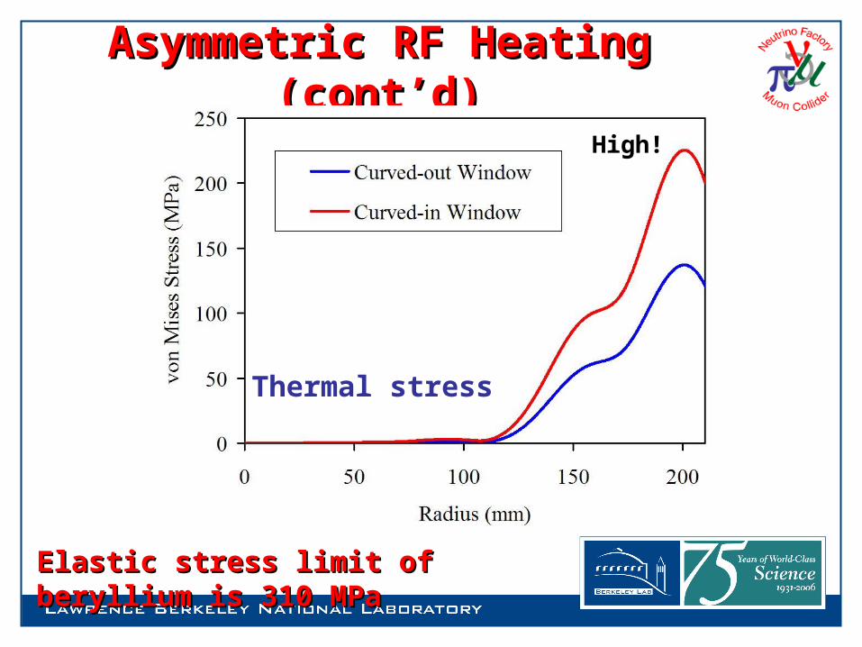
Asymmetric RF Heating (cont’d)Asymmetric RF Heating (cont’d)
Thermal stress
Elastic stress limit of beryllium is 310 MPaElastic stress limit of beryllium is 310 MPa
High!
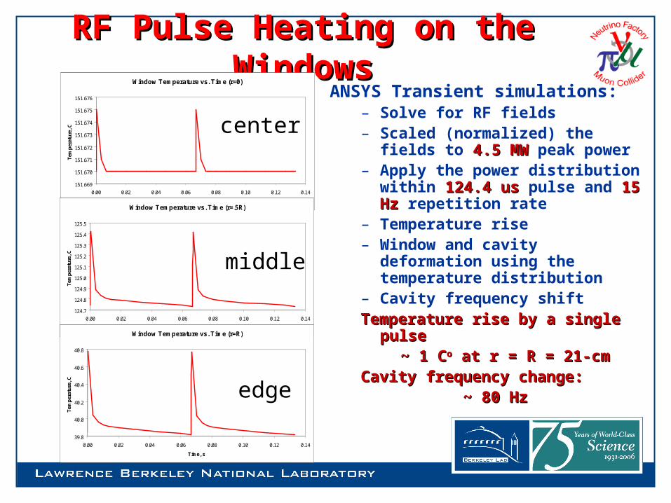
RF Pulse Heating on the WindowsRF Pulse Heating on the WindowsANSYS Transient simulations:
– Solve for RF fields – Scaled (normalized) the fields
to 4.5 MW4.5 MW peak power– Apply the power distribution
within 124.4 us124.4 us pulse and 15 Hz15 Hz repetition rate
– Temperature rise– Window and cavity deformation
using the temperature distribution
– Cavity frequency shiftTemperature rise by a single pulseTemperature rise by a single pulse
~ 1 C~ 1 Coo at r = R = 21-cm at r = R = 21-cmCavity frequency change:Cavity frequency change: ~ 80 Hz~ 80 Hz
Window Temperature vs. Time (r=0)
151.669
151.670
151.671
151.672
151.673
151.674
151.675
151.676
0.00 0.02 0.04 0.06 0.08 0.10 0.12 0.14
Time, s
Tem
per
atu
re, C
Window Temperature vs. Time (r=.5R)
124.7
124.8
124.9
125.0
125.1
125.2
125.3
125.4
125.5
0.00 0.02 0.04 0.06 0.08 0.10 0.12 0.14
Time, s
Tem
per
atu
re, C
Window Temperature vs. Time (r=R)
39.8
40.0
40.2
40.4
40.6
40.8
0.00 0.02 0.04 0.06 0.08 0.10 0.12 0.14
Time, s
Tem
per
atu
re, C
center
middle
edge
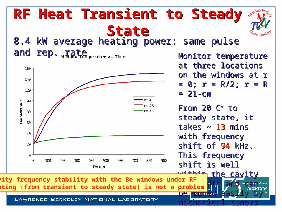
RF Heat Transient to Steady StateRF Heat Transient to Steady State
Window Temperature vs. Time
0
20
40
60
80
100
120
140
160
0 100 200 300 400 500 600 700 800 900
Time, s
Tem
per
atu
re, C
r = 0
r = .5R
r = R
8.4 kW average heating power: same pulse and rep. rate8.4 kW average heating power: same pulse and rep. rate
Monitor temperature at Monitor temperature at three locations on the three locations on the windows at r = 0; r = R/2; windows at r = 0; r = R/2; r = R = 21-cmr = R = 21-cm
From 20 CFrom 20 Coo to steady to steady state, it takes ~ state, it takes ~ 1313 mins mins with frequency shift of with frequency shift of 9494 kHz. This frequency shift kHz. This frequency shift is well within the cavity is well within the cavity bandwidth and can be bandwidth and can be tuned easily by tuned easily by mechanical tunersmechanical tuners
Cavity frequency stability with the Be windows under RF heating (from transient to steady state) is not a problem

Preliminary Test: Setup at MTA Preliminary Test: Setup at MTA
Loop power coupler Loop power coupler
Portable clean room Movable cavity support
The cavity
201 MHz coaxial RF power line
RF probes
Vacuum pump
Radiation monitor

Cavity Design ParametersCavity Design Parameters• The cavity design parameters
– Frequency: 201.25 MHz– β = 0.87– Shunt impedance (VT2/P): ~ 22 MΩ/m
– Quality factor (Q0): ~ 53,500
– Be window radius and thickness: 21-cm and 0.38-mm
• Nominal parameters for cooling channels in a muon
collider or a neutrino factory – ~ 16 MV/m peak accelerating field
– Peak input RF power ~ 4.6 MW per cavity (85% of Q0, 3 filling time)
– Average power dissipation per cavity ~ 8.4 kW– Average power dissipation per Be window
~ 100 watts

Preliminary TestPreliminary Test
Conditioning started in late Feb. 2006 with– Flat copper windows (plates) with Ti-N coatings– RF diagnostics: field, power & radiation measurements – Good vacuum ~ high 10-9 Torr
Without external magnetic field, the cavity was conditioned very quietly and quickly to reach
~ 16 MV/m successfully
Gradient is limited by RF power of 4.2 MW due to the modulator.
2 [M
V/m
]/d
ivis
ion
0.1 ms/division

SummarySummary• The cavity reached design gradient of 16 MV/m
successfully with almost no hard MPs:– Careful handling of the cavity– Good and clean surface finish
• EP and high pressure water rinsing
– Ti-N coatings of the windows
• Test plan being actively developed to include test studies with– Thin and curved Be windows– RF heating on the windows: transient and steady state– External magnetic fields and achievable gradients versus the
magnetic fields– Numerical and experimental studies of MP for the 201 MHz
cavity


![INDEX [ncrb.org]ncrb.org/Portals/5/ncrf/forms/2015 NCRF Private Passenger Auto Rate... · INDEX Page(s) Section A - Summary of Revision ... 33 Reinsurance - nonproportional assumed](https://img.pdfslide.net/doc/110x75/5bfc16c509d3f264188ba139/index-ncrborgncrborgportals5ncrfforms2015-ncrf-private-passenger-auto-rate.jpg)