Embed Size (px)
Citation preview


Revised 02//11/2010
I. INTRODUCTION
A. PURPOSE The intent of these guidelines is to establish SHA’s policy on the proper use and application of longitudinal rumble strips (shoulder and centerline), transverse rumble strips, and rumble stripes on Maryland’s highway system. These guidelines consolidate MSHA’s Draft Directive and Guidance on the Use of Longitudinal Rumble Strips (date Revised May 14, 2002), Use of Temporary Transverse Rumble Strips in Work Zones (SHAs Work Zone Safety Toolbox) and new information into a single document.
B. TARGET USERS State Highway Administration (SHA) staff/engineers, consultants, and local government agencies.
II. DEFINITIONS Rumble Strips: Rumble Strips are raised or grooved patterns on the roadway or shoulder that provide audible and vibratory warnings to drivers that their vehicles are leaving the driving lane or are approaching an unusual or unexpected traffic or road condition. Shoulder Rumble Strips: Shoulder rumble strips are located along the shoulder to alert road users that they are leaving the travel lanes. Centerline Rumble Strips: Centerline rumble strips are rumble strips with centerline pavement markings applied over top of the rumble strips. They warn drivers whose vehicles are crossing centerlines to avoid potential crashes with opposing traffic or run off the road to the left crashes. Transverse Rumble Strips: Transverse rumble strips extend across the travel lane to alert drivers to unusual traffic conditions. Applied Rumble Strips: Rumble strips that are created by placing pavement marking tape or other product on the roadway surface. Milled or Ground Rumble Strips: Rumble strips that are created by milling or grinding depressions into the pavement surface (either Hot Mix Asphalt or Portland Cement Concrete). Rumble Stripes: Rumble Stripes are created by placing edgeline pavement markings over top of shoulder rumble strips.
Guidelines for Application of Rumble Strips and Rumble Stripes
Revised 02/11/2010
3
III. POTENTIAL APPLICATIONS
This document provides guidance on where and how to install rumble strips and rumble stripes. Except in unusual circumstances as determined by engineering judgment, these devices should be installed in accordance with this guidance. In addition to the guidelines described herein, implementation of rumble strips should conform to the applicable guidelines in the MdMUTCD section 6F.84.
A. SHOULDER RUMBLE STRIPS Shoulder rumble strips may be used along roadways with shoulders to warn motorists that they are leaving the travel lanes. 1. Expressways and Controlled-Access Highways
Shoulder rumble strips should be installed along the inside and outside shoulders of expressways and controlled access highways, with the following exceptions:
• An expressway or controlled-access highway having a posted speed limit of 40
mph or less. • An expressway or controlled-access highway where an engineering study finds
that the installation of shoulder rumble strips is not feasible (e.g., because of shoulder width or condition), the potential safety benefits of rumble strips likely cannot be realized, or that other considerations outweigh the potential safety benefits of rumble strips
• The shoulder is designated for use by buses or for other travel • As otherwise precluded in these guidelines
Shoulder rumble strips may be installed along the beltways and expressways/controlled-access highways inside the beltways with written concurrence of the District Engineer.
2. Other Highways
Shoulder rumble strips should be installed along the inside and outside of other divided highways, and along the outside shoulder of undivided highways where the posted speed limit is 40 mph or greater, except as otherwise precluded in these guidelines. Unless an extraordinary circumstance exists, shoulder rumble strips should not be installed along highways where the posted speed limit is less than 40 mph.
3. Roadways Where Bicycles are Permitted
Along expressways where bicycles are expressly permitted to travel and along other highways where shoulder rumble strips are desirable, the accommodation of bicyclists must be considered. The following apply to these highways:
Guidelines for Application of Rumble Strips and Rumble Stripes
Revised 02/11/2010
4
Shoulder Widths • Where the paved outside shoulder is five feet or greater in width, rumble strips are
to be installed in accordance with the typicals shown in Section IV.A. of this document.
• Where the outside shoulder is less than five feet in width:
- The installation of rumble strips is to be coordinated with the Bicycle Coordinator within the Office of Planning and Preliminary Engineering, who will provide the needed coordination with the Bicycle and Pedestrian Advisory Committee.
- Consideration should be given to the need for and benefit of installing minimum width rumble strips (lateral length), minimum depth rumble strips, and/or placed closer to the edge of the roadway.
- Consideration should be given to the need for and benefit of installing rumble stripes.
• Roadway corridors with segments that have deficient shoulder widths should not
preclude the use of shoulder rumble strips for the entire corridor. Deficient shoulders are defined as shoulders where the lateral distance from the outside edge of the rumble strip to the outside edge of the shoulder is less than 4 feet or to the face of traffic barrier is less than 5 feet. In these segments rumble strips should not be installed for the length that the deficient shoulder exists. In determining the minimum clear width, consideration should be given to decreasing the width of the rumble strips and/or placing them closer to the roadway edge, and the use of rumble stripes.
• Shoulder widths should be based on actual field measurements and not on reliance
of widths shown on plans, as-builts, or inventories. Gaps
• No gaps for bicyclists are to be provided along highways where the posted speed limit is 55 mph or greater.
• Although safety is maximized by continuous rumble strips, for highways where the posted speed limit is less than 55 mph, gaps for bicyclists shall be installed.
• Gaps should be installed with a 60-foot pattern (12-foot gap following a 48-foot length of rumble strips). This pattern can be adjusted to accommodate specific milling equipment or for other sound reasons; however, the gap should not be less than 8 feet nor greater than 12 feet and gaps should not be spaced less than 36 feet or more than 60 feet apart.
Additional Guidance and Consideration
• Noise from rumble strip hits should be considered when determining whether to install rumble strips and rumble stripes near residential areas or other sensitive
Guidelines for Application of Rumble Strips and Rumble Stripes
Revised 02/11/2010
5
receptors. This should be a secondary consideration to safety. (The National Cooperative Highway Research Program (NCHRP) has hired Midwest Research Institute to conduct a study entitled “Guidance for the Design and Application of Shoulder and Centerline Rumble Strips.” Several unresolved issues with installing either centerline or shoulder rumble strips will be addressed including “noise produced by rumble strips on adjacent residents.” The study began in July 2005 and was completed in June 2007. A survey was conducted of state transportation agencies to rank concerns regarding installation of rumble strips. Although the exact scope of the study has not been determined, based on conversations with the lead investigator at Midwest Research Institute, noise produced by rumble strips ranked highly and will likely be investigated in detail.)
• Rumble strips and rumble stripes should not be installed where the surface
condition is inadequate for their installation or, except for unusual circumstances, where resurfacing or other work that would substantially decrease the effectiveness of the strips is anticipated within the next two years.
• Rumble stripes may be installed in lieu of shoulder rumble strips with the
concurrence of the Director, Office of Traffic and Safety, the District Engineer, and the Director, Office of Maintenance. See Section III.E. for further discussion of Rumble Stripes.
• More experienced bicyclists have expressed desire to ride between the edgeline
and the rumble strip to avoid debris that commonly collects along the shoulders to the right of the rumble strip. Keeping the shoulders reasonably free from debris through periodic brooming and by the prompt removal of disabled vehicles (within the limits of Maryland law) will promote proper shoulder usage by bicyclists (i.e. riding to the right of the rumble strip).
B. CENTERLINE RUMBLE STRIPS
Centerline rumble strips may be installed along an undivided highway with a 40 mph or greater posted speed limit and 10 foot or greater lane widths in a generally rural area where an engineering study has determined that their installation will improve safety. Other less invasive measures should be tried before rumble strip installation is recommended. Factors that may indicate a need for centerline rumble strips include:
• A high rate or number of head-on or run off the road to the left crashes • A high number or rate of crashes involving fatigued drivers • High volumes that increase the probability of head-on or run off the road to the
left crashes Centerline rumble strips should NOT be installed:
• In the area of intersections with public roads. Centerline rumble strips should be stopped 25 to 50 feet (25 feet for lower speed roadways and up to 50 feet for
Guidelines for Application of Rumble Strips and Rumble Stripes
Revised 02/11/2010
6
higher speed roadways) in advance of the point of curvature of intersections or at the beginning of the taper for the left-turn lane.
• In areas with a high density of access points or in areas with short distances between access points
Installation of centerline rumble strips requires the written concurrence of the District Engineer. Additional Guidance and Consideration
• Centerline rumble strips may be installed in passing zones; however, the noise impacts to residential areas nearby should be considered.
C. TRANSVERSE RUMBLE STRIPS
Transverse rumble strips may be used to attract the driver’s attention to unexpected conditions or to bring the driver’s attention to other warning devices. Transverse rumble strips may be considered for the following conditions: 1. Approaches to Intersections (Signalized, Stop Controlled, Roundabouts)
Transverse rumble strips should be considered on the approaches to intersections where there is a demonstrated safety problem (e.g. high crash rate), adequate trial of other warning devices has failed to reduce the crash frequency, and any of the following conditions exist:
• Inadequate stopping sight distance or signal/sign visibility • Intersection is at an unexpected location • Intersection is located where motorists have not been required to stop for a long
period of time or distance 2. Approaches to Horizontal Curves
Transverse rumble strips should be considered on the approaches to horizontal curves where there is a demonstrated safety problem (e.g. high crash rate), adequate trial of other warning devices has failed to reduce the crash frequency, and any of the following conditions exist:
• A significant speed reduction from the posted speed limit is required to safely traverse the curve
• Curve is located at an unexpected location 3. Approaches to Reduced Speed Zones
Transverse rumble strips should be considered on the approaches to reduced speed zones where an engineering study finds that excessive speeding is a problem in a reduced speed zone and adequate trial of other regulatory devices has failed to reduce the occurrence of speeding. Factors that may indicate a need include:
• Posted speed reduction of 20 mph or greater

Guidelines for Application of Rumble Strips and Rumble Stripes
Revised 02/11/2010
7
• Entrance to a town, business district, or location where significant pedestrian activity is anticipated
• The character of the roadway changes, such as at the end of a freeway 4. Approaches to Toll Plazas
Transverse rumble strips should be considered on the approaches to Toll Plazas where motorists are required to stop or slow to pay a toll.
5. Approaches to Work Zones
Transverse rumble strips may be used in work zones in advance of detours, flaggers, lane splits, crossovers, lane transitions, exit only lanes, lane closures, temporary traffic signals, and locations with major reductions in speed limits. Transverse rumble strips are not generally used for short-term maintenance related construction. When installed on a temporary basis, rumble strips should be sufficiently durable to cover the period of need. When temporary rumble strips are no longer needed, they should be removed from the pavement and the pavement should be cleaned and restored to normal conditions.
Additional Guidance and Consideration
• Other less invasive measures should be tried before transverse rumble strips are recommended.
• Transverse rumble strips should be used with care at locations with high bicycle
and motorcycle traffic.
• Transverse rumble strips should not be placed on roadways used by bicyclists unless a minimum clear path of 4 feet is provided at each edge of the roadway or each paved shoulder as described in AASHTO’s “Guide to the Development of Bicycle Facilities.”
• Transverse rumble strips may be supplemented with additional pavement marking
warning messages such as “STOP AHEAD” or “SIGNAL AHEAD” where the purpose of the rumble strips may not be clear.
• The use of transverse rumble strips near residential areas or other sensitive noise
receptors should be carefully evaluated.
• Transverse rumble strips should not be placed on sharp horizontal or vertical curves.
• The use of transverse rumble strips in shoulders to deter motorists from traveling in the shoulder for long distances where there is specific justification for their installation requires the written concurrence of the Director, Office of Traffic and Safety and the Director, Office of Maintenance. Transverse rumble strips should not be installed in shoulders where bicycle activity is anticipated.
Guidelines for Application of Rumble Strips and Rumble Stripes
Revised 02/11/2010
8
D. RUMBLE STRIPS BETWEEN LANES With specific justification and the concurrence of the Director, Office of Traffic and Safety and the Director, Office of Maintenance, rumble strips may be installed between adjacent lanes moving in the same direction at the following locations:
• Where there is a need to further discourage prohibited lane changing • Between the through lanes and collector/distributor lanes where there is no
physical barrier
E. RUMBLE STRIPES For expressways and controlled-access highways that do not have shoulders or shoulders wide enough for shoulder rumble strips, rumble stripes may be installed. For all other highways that do not have shoulders or shoulders wide enough for both shoulder rumble strips and bicycle use (48” min.), rumble stripes may be installed. Rumble stripes may be installed along a highway with a 40 mph or greater posted speed limit and 11 foot or greater lane widths in a generally rural area where an engineering study has determined that their installation will improve safety. Other less invasive measures should be tried before rumble stripe installation is recommended. Factors that may indicate a need for rumble stripes include:
• A high rate or number of run off the road crashes • A high number or rate of crashes involving fatigued drivers • High volumes that increase the probability of run off the road crashes
Rumble stripes should NOT be installed:
• In the area of intersections with public roads. Rumble stripes should be stopped 25 to 50 feet (25 feet for lower speed roadways and up to 50 feet for higher speed roadways) in advance of the point of curvature of intersections or at the beginning of the taper for the turn lanes.
• In areas with a high density of access points or in areas with short distances between access points
Installation of rumble stripes requires the written concurrence of the Director, Office of Traffic and Safety, the District Engineer, and the Director, Office of Maintenance.
Guidelines for Application of Rumble Strips and Rumble Stripes
Revised 02/11/2010
9
IV. DESIGN GUIDELINES The following guidelines apply to the design and installation of all rumble strips and rumble stripes:
• Milled or ground rumble strips and rumble stripes are not to be installed on Portland Cement Concrete bridge decks or on Portland Cement Concrete bridge approach slabs.
• Milled or ground rumble strips and rumble stripes can be used on new or existing
pavement. To retrofit rumble strips and rumble stripes on existing pavement, the pavement should be in sufficiently good condition to effectively accept the milling process without raveling or deteriorating. Otherwise the pavement should be upgraded prior to milling any desired rumble strips and rumble stripes.
• To the extent practicable, rumble strips and rumble stripes should avoid in-surface
vehicle detectors and their leads, other highway wiring, raised pavement markers (RPMs), other traffic control devices, and other highway appurtances.
A. SHOULDER RUMBLE STRIPS
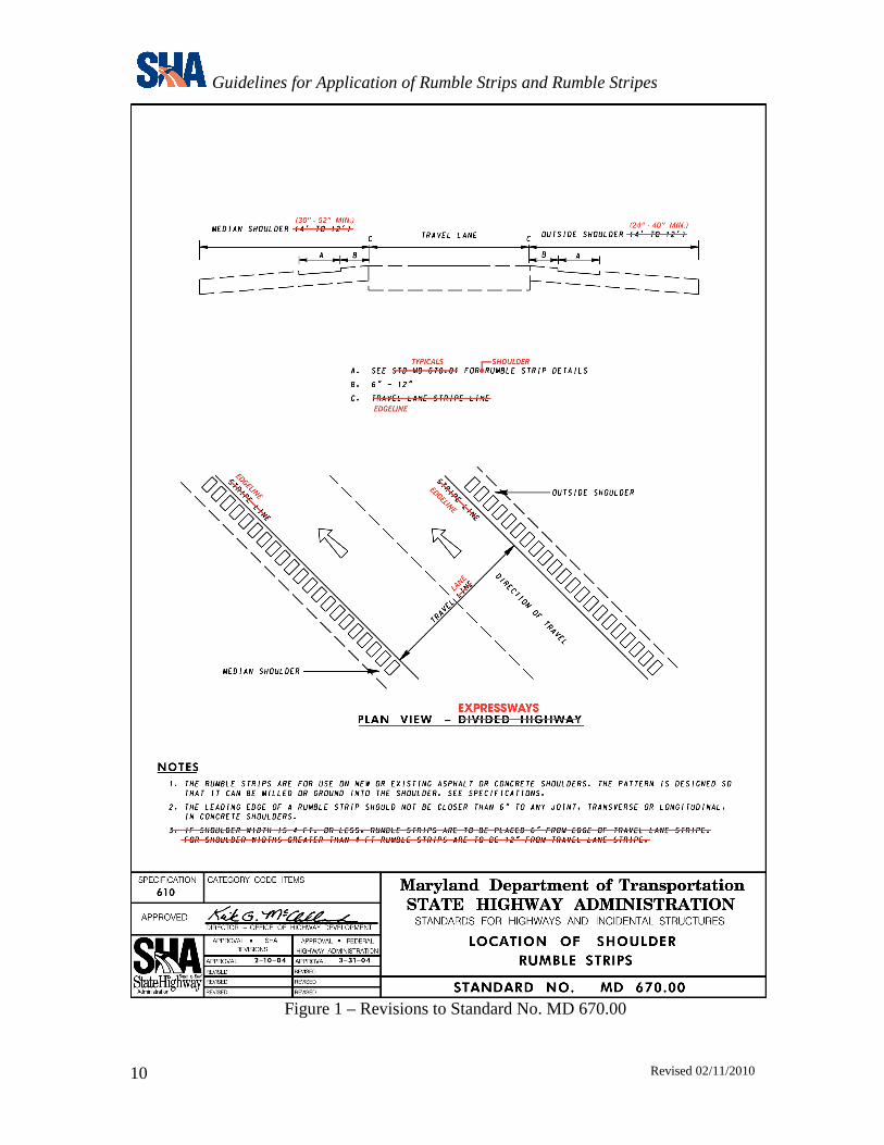
Shoulder rumble strips are to be milled or ground into the pavement surface. With the concurrence of the Director, Office of Traffic and Safety and the Director, Office of Maintenance, applied shoulder rumble strips may be used on an experimental basis. Shoulder rumble strips and rumble stripes are to be installed in accordance with the details and typicals shown in the following figures.
• Figure 1 – Revise Standard No. MD 670.00
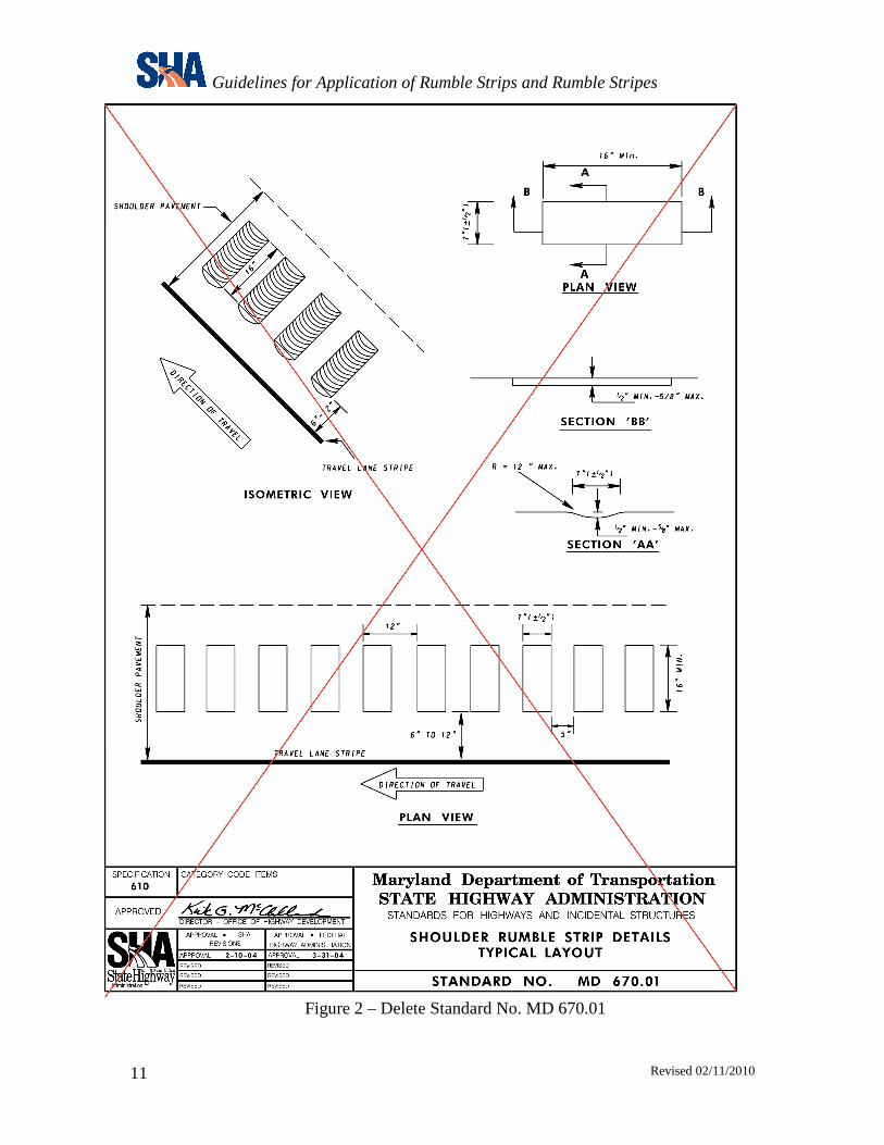
• Figure 2 – Delete Standard No. MD 670.01, and replace with Typical No. 1
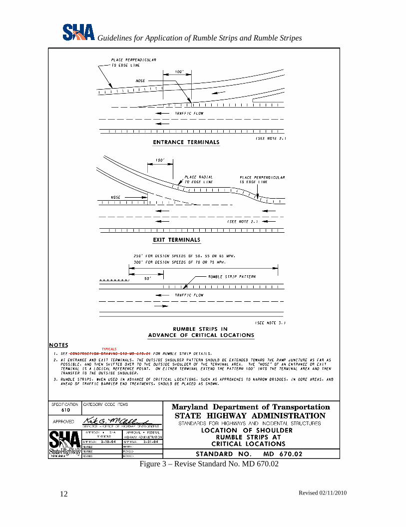
• Figure 3 – Revise Standard No. MD 670.02
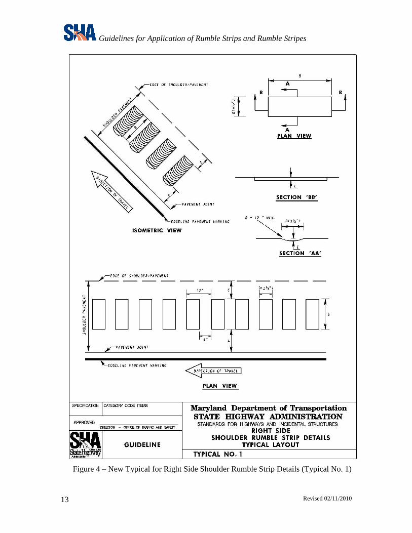
• Figure 4 – New Typical for Right Side Shoulder Rumble Strip Details (Typical No. 1)
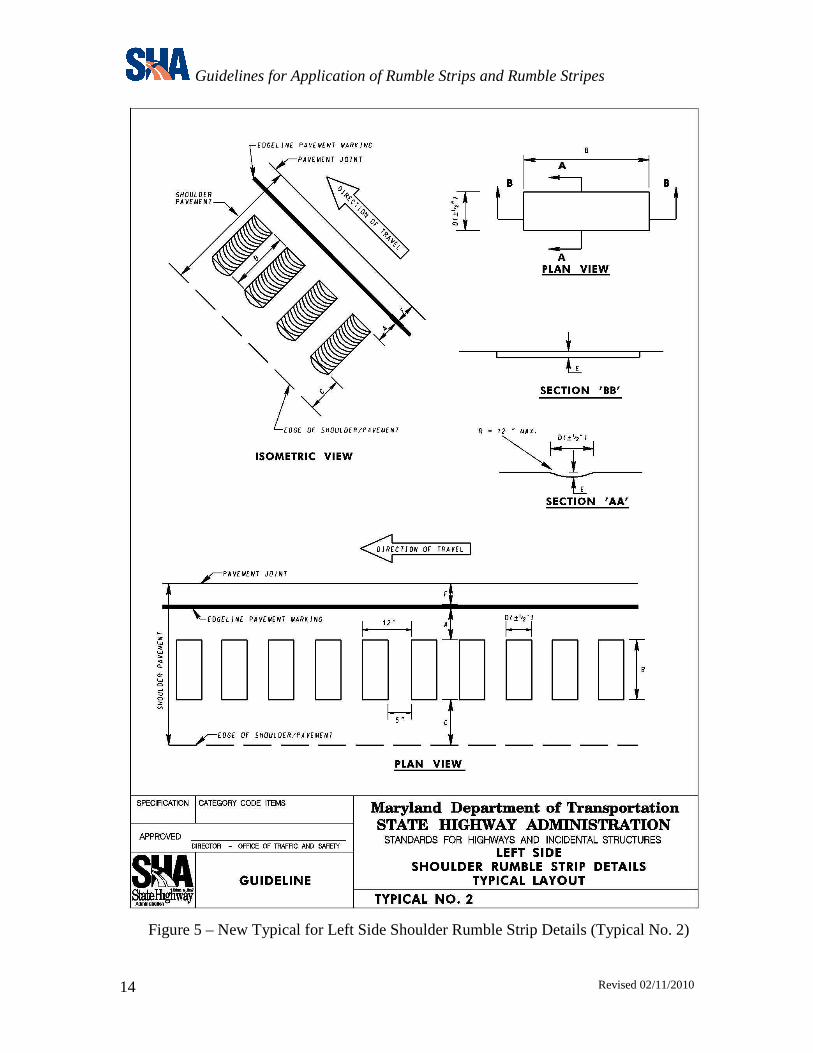
• Figure 5 – New Typical for Left Side Shoulder Rumble Strip Details (Typical No. 2)
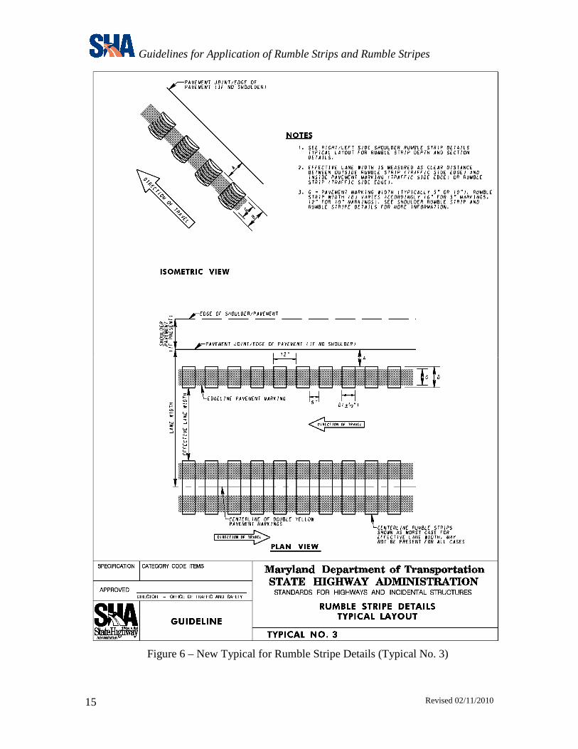
• Figure 6 – New Typical for Rumble Stripe Details (Typical No. 3)
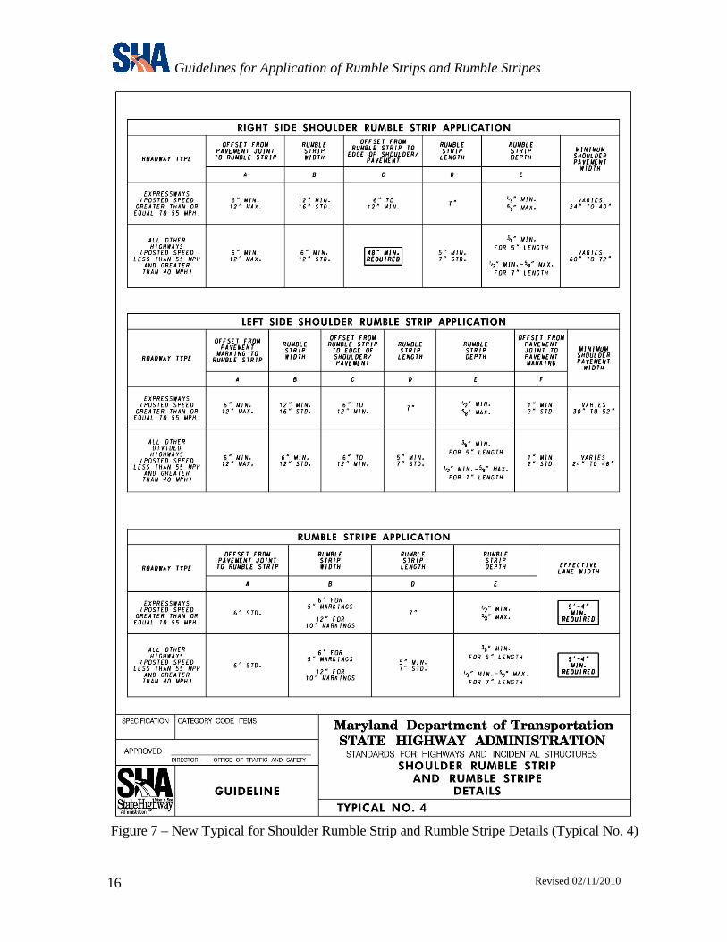
• Figure 7 – New Typical for Shoulder Rumble Strip and Rumble Stripe Details (Typical No. 4)
Guidelines for Application of Rumble Strips and Rumble Stripes
Revised 02/11/2010
10
Figure 1 – Revisions to Standard No. MD 670.00
Guidelines for Application of Rumble Strips and Rumble Stripes
Revised 02/11/2010
11
Figure 2 – Delete Standard No. MD 670.01
Guidelines for Application of Rumble Strips and Rumble Stripes
Revised 02/11/2010
12
Figure 3 – Revise Standard No. MD 670.02
Guidelines for Application of Rumble Strips and Rumble Stripes
Revised 02/11/2010
13
Figure 4 – New Typical for Right Side Shoulder Rumble Strip Details (Typical No. 1)
Guidelines for Application of Rumble Strips and Rumble Stripes
Revised 02/11/2010
14
Figure 5 – New Typical for Left Side Shoulder Rumble Strip Details (Typical No. 2)
Guidelines for Application of Rumble Strips and Rumble Stripes
Revised 02/11/2010
15
Figure 6 – New Typical for Rumble Stripe Details (Typical No. 3)
Guidelines for Application of Rumble Strips and Rumble Stripes
Revised 02/11/2010
16
Figure 7 – New Typical for Shoulder Rumble Strip and Rumble Stripe Details (Typical No. 4)
Guidelines for Application of Rumble Strips and Rumble Stripes
Revised 02/11/2010
17
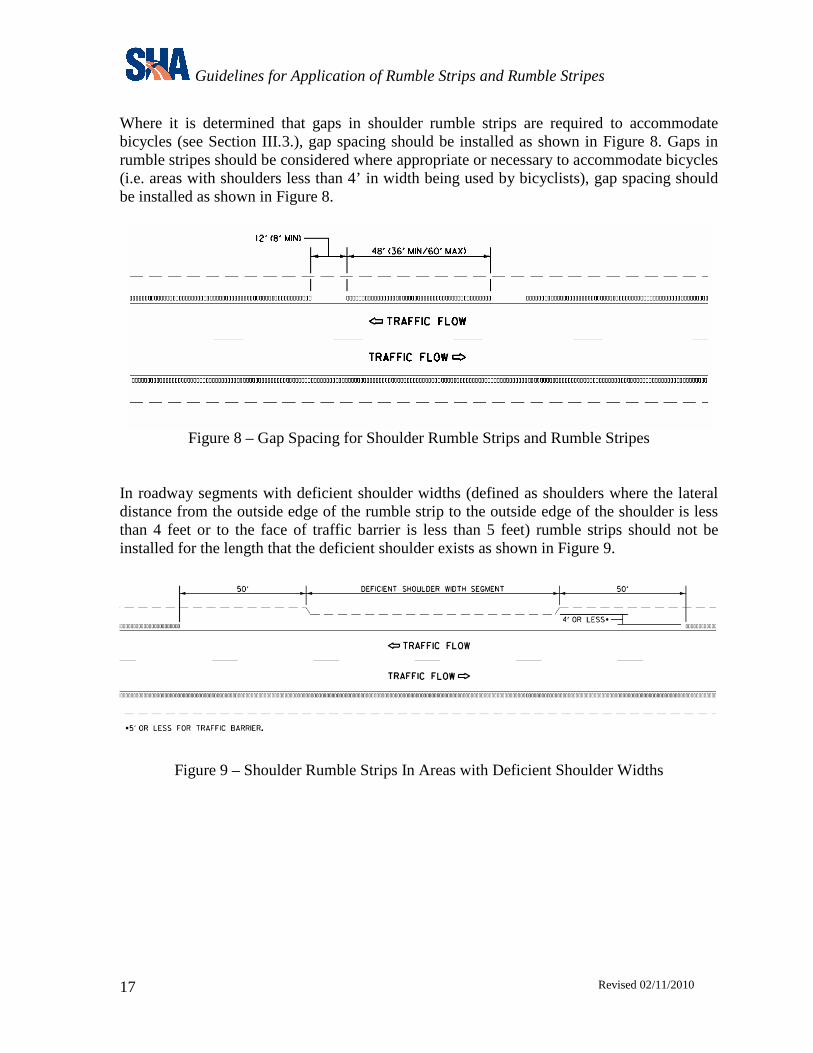
Where it is determined that gaps in shoulder rumble strips are required to accommodate bicycles (see Section III.3.), gap spacing should be installed as shown in Figure 8. Gaps in rumble stripes should be considered where appropriate or necessary to accommodate bicycles (i.e. areas with shoulders less than 4’ in width being used by bicyclists), gap spacing should be installed as shown in Figure 8.
Figure 8 – Gap Spacing for Shoulder Rumble Strips and Rumble Stripes
In roadway segments with deficient shoulder widths (defined as shoulders where the lateral distance from the outside edge of the rumble strip to the outside edge of the shoulder is less than 4 feet or to the face of traffic barrier is less than 5 feet) rumble strips should not be installed for the length that the deficient shoulder exists as shown in Figure 9.
Figure 9 – Shoulder Rumble Strips In Areas with Deficient Shoulder Widths
Guidelines for Application of Rumble Strips and Rumble Stripes
Revised 02/11/2010
18
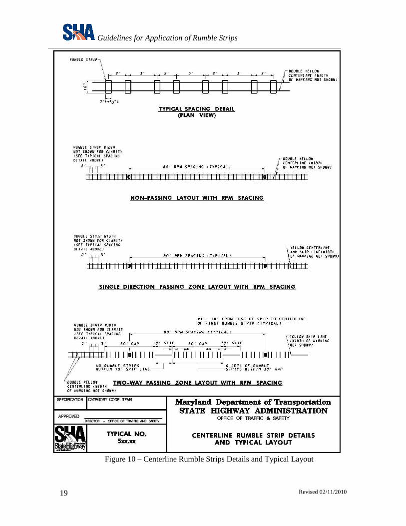
B. CENTERLINE RUMBLE STRIPS Centerline rumble strips are to be milled or ground into the pavement surface with pavement marking material applied over top. With the concurrence of the Director, Office of Traffic and Safety and the Director, Office of Maintenance, applied centerline rumble strips may be used on an experimental basis. Installation of centerline rumble strips should be coordinated with permanent pavement marking and RPM placement. Permanent pavement markings and RPMs should be installed after installation of the rumble strips is complete. Liquid applied pavement marking materials such as, thermoplastic or paint shall be used for centerline markings in conjunction with centerline rumble strips. Centerline rumble strips should be spaced along the centerline of a roadway as shown in Figure 10. Installation of raised pavement markers (RPMs) with centerline rumble strips as shown in Figure 10 is optional. Centerline rumble strips should be stopped 25 to 50 feet (25 feet for lower speed roadways and up to 50 feet for higher speed roadways) in advance of the point of curvature of intersections or at the beginning of the taper for the left-turn lane.
Guidelines for Application of Rumble Strips
Revised 02/11/2010
19
Figure 10 – Centerline Rumble Strips Details and Typical Layout
Guidelines for Application of Rumble Strips
Revised 02/11/2010
20
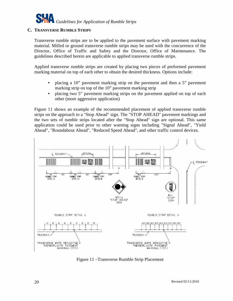
C. TRANSVERSE RUMBLE STRIPS Transverse rumble strips are to be applied to the pavement surface with pavement marking material. Milled or ground transverse rumble strips may be used with the concurrence of the Director, Office of Traffic and Safety and the Director, Office of Maintenance. The guidelines described herein are applicable to applied transverse rumble strips. Applied transverse rumble strips are created by placing two pieces of preformed pavement marking material on top of each other to obtain the desired thickness. Options include:
• placing a 10” pavement marking strip on the pavement and then a 5” pavement marking strip on top of the 10” pavement marking strip
• placing two 5” pavement marking strips on the pavement applied on top of each other (more aggressive application)
Figure 11 shows an example of the recommended placement of applied transverse rumble strips on the approach to a "Stop Ahead" sign. The "STOP AHEAD" pavement markings and the two sets of rumble strips located after the "Stop Ahead" sign are optional. This same application could be used prior to other warning signs including "Signal Ahead", "Yield Ahead", "Roundabout Ahead", "Reduced Speed Ahead", and other traffic control devices.
Figure 11 –Transverse Rumble Strip Placement
Guidelines for Application of Rumble Strips
Revised 02/11/2010
21
D. RUMBLE STRIPS BETWEEN LANES
The specific design (width, spacing, lateral placement, etc.) of rumble strips to be installed between lanes should be selected based on the identified problems and specific traffic, roadway, and area conditions; and approved by the Director, Office of Traffic and Safety.
E. RUMBLE STRIPES Rumble stripes are to be milled or ground into the pavement surface with pavement marking material applied over top. Installation of rumble stripes should be coordinated with permanent pavement marking and RPM placement. Permanent pavement markings and RPMs shall be installed after installation of the rumble strips is complete. Typically thermoplastic or paint materials shall be used for rumble stripe markings. Preformed tape materials shall not be used for rumble stripe application. Rumble stripes should be installed as shown in Figures 6 & 7. Rumble stripes should be stopped 25 to 50 feet (25 feet for lower speed roadways and up to 50 feet for higher speed roadways) in advance of the point of curvature of intersections or at the beginning of the taper for the left-turn lane. One of the key considerations for the installation of rumble stripes is maintaining a minimum effective lane width. Effective lane width is defined as the clear distance between a pavement marking or centerline rumble strip on the left side of the travel lane and the rumble strip associated with the rumble stripe on the right side of the travel lane. The minimum effective lane width that should be maintained is 9’- 4”. This is calculated assuming a minimum travel lane width (measured from the roadway centerline to the pavement joint/edge) of 11’ and subtracting 8” for half the width of centerline rumble strips, 6” for the minimum offset for rumble strips from the pavement joint/edge, and 6” for the rumble strip/stripe width. Another consideration for the installation of rumble stripes is maintaining the existing shoulder width for bicycle use, regardless of whether the width meets 48” minimum required by current standards. The intent is not to remove the current usable bicycle area in order to install rumble stripes. For roadways with no shoulders consideration should be given to bicycle accommodations with rumble stripes. See Section III.A.3. for further guidance.

Guidelines for Application of Rumble Strips
Revised 02/11/2010
22
SPECIAL PROVISIONS

Guidelines for Application of Rumble Strips
Revised 02/11/2010
23
SPECIAL PROVISIONS CONTRACT NO. XXX 610 – RUMBLE STRIPS
1 of 1 CATEGORY 600
SHOULDERS
SECTION 610 — SHOULDER RUMBLE STRIPS 610.01 DESCRIPTION. This work shall consist of grinding depressions into existing Hot Mix Asphalt and Portland Cement Concrete to form shoulder rumble strips at the locations specified in the Contract Documents or as directed by the Engineer. 610.02 MATERIALS. Not applicable. 610.03 CONSTRUCTION. General. The rumble strip placement shall conform to the Contract Documents. The rumble strips shall be ground into Hot Mix Asphalt (HMA) at a minimum rate of 4000 per hour, and into Portland Cement Concrete at a minimum rate of 1000 per hour. Equipment. The equipment shall have rotary type cutting heads with a maximum outside diameter of 24 in. and a length of 16 in. The cutting heads shall have the cutting tips arranged in a pattern providing a relatively smooth cut (approximately 1/16 in. between peaks and valleys). The cutting heads shall be mounted on their own suspension, independent of the power unit, to allow the tool to self-align with the slope of the shoulder and any irregularities in the shoulder surface. The cutting tool shall be equipped with guides to provide consistent alignment of each cut in relation to the roadway and to provide uniformity throughout the project. Alignment of the edge of the pattern will be randomly checked by the Engineer. Control Strip. The Contractor shall grind a 100 ft minimum control strip to demonstrate to the Engineer that the speed of operation, dimensions, and texture are acceptable. Clean up. The pavement shall be cleaned by sweeping or vacuuming the work area before the roadway is reopened to traffic. Waste material resulting from the operation shall be removed from the site, and disposed of in a manner approved by the Engineer. The material shall not be swept to the side of the road. 610.04 MEASUREMENT AND PAYMENT. Shoulder Rumble Strips in Hot Mix Asphalt and Portland Cement Concrete will be measured and paid for at the Contract unit price per linear foot as measured along the shoulder or center line of the roadway, within the limits of work. Payment will be full compensation for all installation of rumble strips, cleaning and disposal of waste material, control strips, and for all material, labor, equipment, tools, and incidentals necessary to complete the work.
Guidelines for Application of Rumble Strips
Revised 02/11/2010
24
SPECIAL PROVISIONS CONTRACT NO. XXX 5xx – CENTERLINE RUMBLE STRIPS
1 of 1 CATEGORY 500
PAVING
SECTION 5xx — CENTERLINE AND BETWEEN LANE RUMBLE STRIPS 5xx.01 DESCRIPTION. This work shall consist of grinding depressions into existing Hot Mix Asphalt and Portland Cement Concrete roadways to form centerline and/or between lane rumble strips at the locations specified in the Contract Documents or as directed by the Engineer. 5xx.02 MATERIALS. Not applicable. 5xx.03 CONSTRUCTION. General. The rumble strip placement shall conform to the Contract Documents. The centerline rumble strips shall be ground into Hot Mix Asphalt (HMA) at a minimum rate of 4000 per hour, and into Portland Cement Concrete at a minimum rate of 1000 per hour. Pavement marking material shall conform to the applicable specifications in the Contract Documents for the material specified. Equipment. The equipment shall have rotary type cutting heads with a maximum outside diameter of 24 in. and a length of 16 in. The cutting heads shall have the cutting tips arranged in a pattern providing a relatively smooth cut (approximately 1/16 in. between peaks and valleys). The cutting heads shall be mounted on their own suspension, independent of the power unit, to allow the tool to self-align with the slope of the roadway and any irregularities in the roadway surface. The cutting tool shall be equipped with guides to provide consistent alignment of each cut in relation to the roadway and to provide uniformity throughout the project. Alignment of the edge of the pattern will be randomly checked by the Engineer. Control Strip. The Contractor shall grind a 100 ft minimum control strip to demonstrate to the Engineer that the speed of operation, dimensions, and texture are acceptable. Clean up. The pavement shall be cleaned by sweeping or vacuuming the work area before the roadway is reopened to traffic. Waste material resulting from the operation shall be removed from the site, and disposed of in a manner approved by the Engineer. The material shall not be swept to the side of the road. 5xx.04 MEASUREMENT AND PAYMENT. Centerline and Between Lane Rumble Strips in Hot Mix Asphalt and Portland Cement Concrete will be measured and paid for at the Contract unit price per linear foot as measured along the center line of the roadway, within the limits of work. Payment will be full compensation for all installation of rumble strips, cleaning and disposal of waste material, control strips, and for all material, labor, equipment, tools, and incidentals necessary to complete the work. Pavement marking materials and RPMs will be measured and paid for separately under the respective items as specified in the Contract Documents.
Guidelines for Application of Rumble Strips
Revised 02/11/2010
25
SPECIAL PROVISIONS CONTRACT NO. XXX 5yy – APPLIED TRANSVERSE RUMBLE STRIPS
1 of 1 CATEGORY 500
PAVING
SECTION 5yy — APPLIED TRANSVERSE RUMBLE STRIPS 5yy.01 DESCRIPTION. This work shall consist of furnishing and installing heat applied preformed thermoplastic pavement marking lines for use as transverse rumble strips as specified in the Contract Documents or as directed by the Engineer. 5yy.02 MATERIALS. Preformed Thermoplastic is a durable pavement marking material. All Preformed Thermoplastic Pavement Marking material shall be selected from the Qualified Products List. Heat Applied Permanent Preformed Thermoplastic Pavement Marking Material 951.06 5yy.03 CONSTRUCTION. Refer to 556 5yy.04 MEASUREMENT AND PAYMENT. Applied Transverse Rumble Strips will be measured along the length installed multiplied by the number of layers, per each rumble strip within a set of rumble strips. Applied Transverse Rumble Strips will be paid for at the Contract unit price per linear foot for the color and width specified under the appropriate Preformed Thermoplastic Pavement Marking line items. The payment will be full compensation for all pavement preparation, furnishing and placing of markings, testing, and for all material, labor, equipment, tools, and incidentals necessary to complete the work.

Guidelines for Application of Rumble Strips
Revised 02/11/2010
26
SPECIAL PROVISIONS CONTRACT NO. XXX 5zz – RUMBLE STRIPES
1 of 1 CATEGORY 500
PAVING
SECTION 5zz —RUMBLE STRIPES 5zz.01 DESCRIPTION. This work shall consist of grinding depressions into existing Hot Mix Asphalt and Portland Cement Concrete roadways to form rumble strips for the application of edgeline pavement marking materials over top of the rumble strip. The finished product is referred to as rumble stripes at the locations specified in the Contract Documents or as directed by the Engineer. 5zz.02 MATERIALS. Not applicable. 5zz.03 CONSTRUCTION. General. The rumble stripe placement shall conform to the Contract Documents. The centerline rumble strips shall be ground into Hot Mix Asphalt (HMA) at a minimum rate of 4000 per hour, and into Portland Cement Concrete at a minimum rate of 1000 per hour. The edgeline pavement marking material shall conform to the applicable specifications in the Contract Documents for the material specified. Equipment. The equipment shall have rotary type cutting heads with a maximum outside diameter of 24 in. and a length of 16 in. The cutting heads shall have the cutting tips arranged in a pattern providing a relatively smooth cut (approximately 1/16 in. between peaks and valleys). The cutting heads shall be mounted on their own suspension, independent of the power unit, to allow the tool to self-align with the slope of the roadway and any irregularities in the roadway surface. The cutting tool shall be equipped with guides to provide consistent alignment of each cut in relation to the roadway and to provide uniformity throughout the project. Alignment of the edge of the pattern will be randomly checked by the Engineer. Control Strip. The Contractor shall grind a 100 ft minimum control strip to demonstrate to the Engineer that the speed of operation, dimensions, and texture are acceptable. Clean up. The pavement shall be cleaned by sweeping or vacuuming the work area before the roadway is reopened to traffic. Waste material resulting from the operation shall be removed from the site, and disposed of in a manner approved by the Engineer. The material shall not be swept to the side of the road. 5zz.04 MEASUREMENT AND PAYMENT. Rumble Stripes in Hot Mix Asphalt and Portland Cement Concrete will be measured and paid for at the Contract unit price per linear foot as measured along the shoulder or center line of the roadway, within the limits of work. Payment will be full compensation for all installation of rumble strips, cleaning and disposal of waste material, control strips, and for all material, labor, equipment, tools, and incidentals necessary to complete the work. Pavement marking materials will be measured and paid for separately under the respective item as specified in the Contract Documents.