Embed Size (px)
Citation preview
U.S. Department of Energy 2010 Annual Inspection – Piqua, OH, Decommissioned Reactor Site June 2010 Page 1
2010 Annual Inspection and Radiological Survey Results for the Piqua, Ohio,
Decommissioned Reactor Site
Summary The former Piqua Nuclear Power Facility (PNPF), a decommissioned nuclear power demonstration facility, was inspected on April 8, 2010 (PL–1). The site, located on the east bank of the Great Miami River in Piqua, Ohio, is in good physical condition. There is no requirement for a follow-up inspection. The PNPF consists of a reactor containment building and an associated auxiliary building that are both used by Piqua Power Systems (PPS) as storage space, shops, and offices. The city will lease the property until radioactive decay allows the facility to be released for unrestricted use. At that time, ownership reverts to the city. Deterioration in the interior of the containment building, (noted in previous inspections, e.g. peeling lead-based paint, plaster falling off the walls in some areas, worn pipe insulation) appears to be about the same. The cathodic protection system and the high water alarm system continue to be routinely inspected and maintained by PPS. Both were operating satisfactorily. An annual radiological survey was performed in conjunction with the annual inspection. This year samples were collected at 106 locations. Survey results revealed no removable contamination at any of the 106 sample points. Only one direct reading exceeded the minimum detectable activity (MDA): the floor drain at the 56-foot level (2,400 dpm/100 cm2). Beta activity has been detected in the past at the floor drain. The reading is well below the action level of 5,000 dpm/100 cm2. 1.0 Introduction This report presents the findings of the annual U.S. Department of Energy (DOE) inspection of the Piqua Nuclear Power Facility (PNPF) in Piqua, Ohio. This facility is assigned to the DOE Office of Legacy Management (LM) for long-term custody and care. M. Miller (Chief Inspector), K. Broberg, (Assistant Inspector), R. Mowen, (Radiological Technician), all of S.M. Stoller Corporation, the contractor for the DOE Office of Legacy Management conducted the inspection on April 8, 2010. Mr. Wheelock, the Power Systems Director of the Piqua Power Systems (PPS), was contacted and met with inspectors at the start of the inspection. A copy of this report will be forwarded to Mr. Wheelock. The purpose of the inspection was to confirm the integrity of the visible features at the facility and to verify that no radiological or non-radiological hazards are present.

U.S. Department of Energy 2010 Annual Inspection – Piqua, OH, Decommissioned Reactor Site June 2010 Page 2
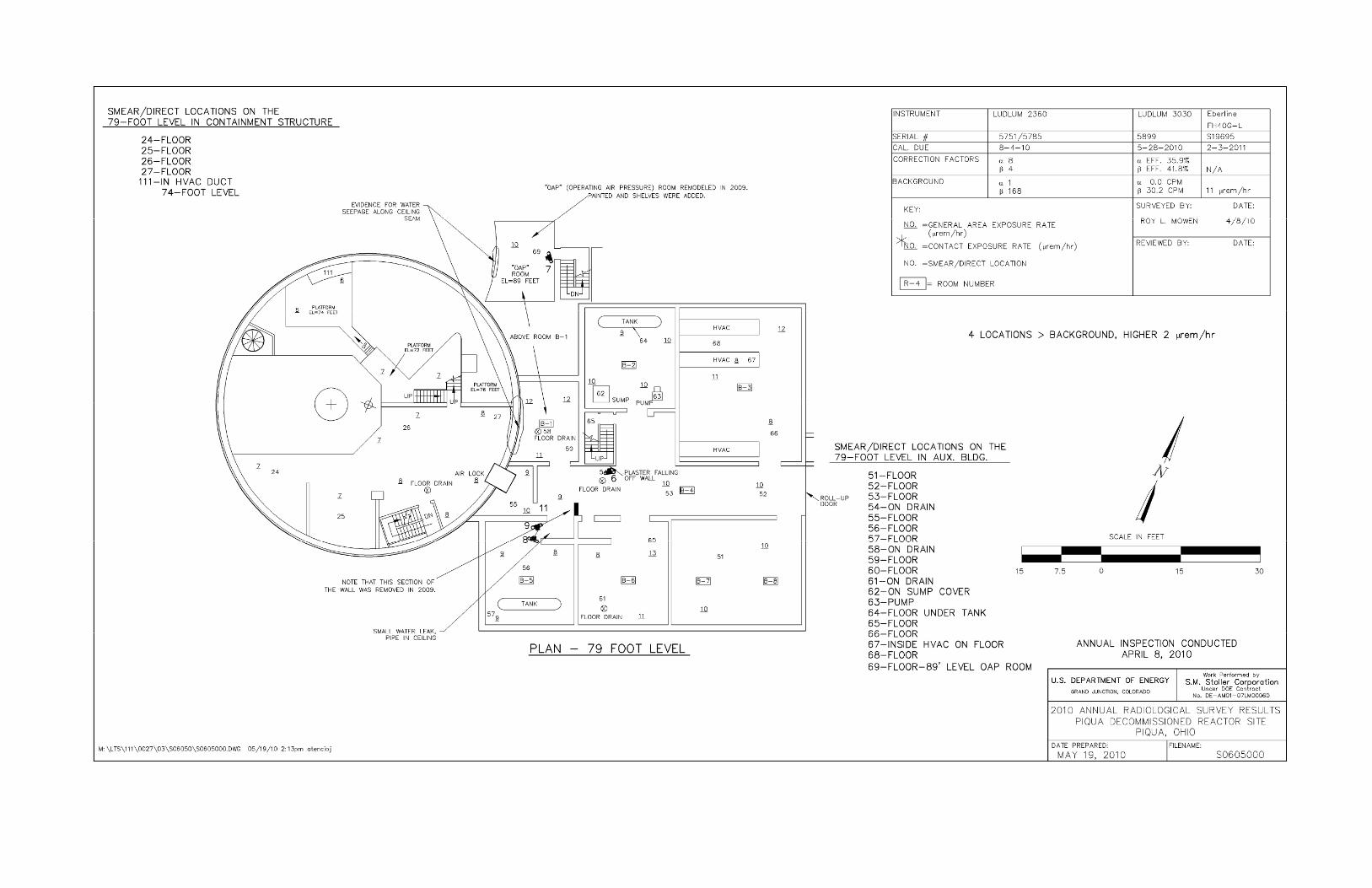
2.0 Inspection Results Features discussed in this report are shown on the attached drawings. Photographs to support specific observations are identified in the text and on the drawings by photograph location (PL) numbers. Exterior The Containment Building exterior was refurbished around 1995. The exterior of the reactor containment building was in good shape (PL–2 and PL–3). Surrounding Area No changes in the area immediately surrounding the Piqua facility were observed. Interior Inspectors examined the facility interior looking for evidence of structural deterioration and entombment degradation. Interior concerns noted in previous inspections remain unchanged (i.e., peeling lead-based paint, falling plaster, and deteriorating pipe insulation). 56-foot level: The 56-foot level is the lowest level of the facility. PPS uses this level to store cable spools. The condition of peeling paint on the interior walls remains unchanged from the 2009 inspection. Peeling paint (that is falling onto the floors) was analyzed in 2006 and found to contain 0.35 percent lead. The paint will probably continue to peel and fall to the floor. Inspectors are not exposed to unacceptable risk when performing routine inspection activities. PPS is aware of the presence of lead-based paint. A spiral staircase is present in the containment structure. Plaster is falling off the walls at the base of the spiral staircase at the 56-foot level. Plaster is damaged just outside the entrance to the spiral staircase at the 56-foot level (PL–4). Cable spools have rolled into the walls, damaging the plaster. This damage has been noted in previous inspection reports. 79-foot level: Conditions concerning broken plaster, peeling paint, and water damage noted in previous inspections appeared to be about the same. The area of broken wall plaster in Room B–4 remained unchanged from last year (PL–6). Evidence for water seeping along the ceiling seam of the Operating Air Pressure (OAP) room was observed (peeling paint and rust stains) (PL–7). This room is located directly above Room B1. Evidence for water seeping from the ceiling seam of Room B–1 was noted during the 2009 inspection. The southwest wall of both rooms is the curved wall of the containment structure. Both rooms show evidence for water seeping along the same wall of the containment building. The condition was noted on the 79-foot level site inspection map. PPS personnel were informed of the condition following the inspection. Water was observed to be slowly dripping down the outside surface of a pipe that extends out of the ceiling of Room B–5 (PL–8). Water stains on the floor of Room B–5 and along the sides of boxes stored in Room B–5 were also observed (PL–9). PPS personnel were informed of the condition following the inspection.

U.S. Department of Energy 2010 Annual Inspection – Piqua, OH, Decommissioned Reactor Site June 2010 Page 3
100-foot level: Water was observed on the floor of Room 125 (PL–10). This room is an outside room off the loading dock. It is no longer used by PPS and is kept locked. Water staining is present along the wall in the back corner of the room (PL–11) as well as around a vent in the ceiling of the room (PL–12). Water was ponded on the corner of the roof above this room; all around the ceiling vent (PL–13). Damage to the outside corner of the room was also observed (PL–14). This damage may be contributing to the water seen inside the room. It is recommended that the outside corner of the room be repaired to minimize further deterioration that might be caused by water/ice interactions. It is further recommended that the reason why water is ponding and not properly draining from the corner of the roof above Room 125 be determined and corrected. The concrete around the base of the outside wall of the containment structure is cracking in several places (PL–15, PL–16, and PL–17). The cracks are allowing water to enter, freeze and expand, and further damage the concrete. It is recommended that the cracks be repaired and any damaged concrete areas be patched while the damage is still minor to avoid larger problems and repair costs in the future. PPS personnel were informed of the finding following the inspection. 2.1 Cathodic Protection System A cathodic protection system is installed on the Containment Building to protect the steel shell. Corrosion of the pressure vessel could allow water to enter and spread radioactive contamination beyond the entombment. The system consists of 10 carbon (graphite) electrodes, buried radially approximately 10 feet to 20 feet from the building foundation, and a rectifier unit that provides DC current. The rectifier unit is mounted in the break room south of and outside the airlock on the 100-foot level. Each carbon electrode is 3 inches in diameter and 60 inches long. The electrodes are connected to the rectifier unit by a header cable; splices are protected in flush-mounted boxes. A structure contact point for monitoring potential can be found on the shell associated with each electrode; some of the contact points also have cables remaining from an abandoned zinc anode protection system. The system also includes reference electrodes and test holes. Maintenance of the cathodic protection system is specifically addressed in Contract AT(11–1)–1798, dated May 10, 1968, between the U.S. Atomic Energy Commission and the City of Piqua. The City agrees to maintain the system in an operational condition as long as required to preserve the integrity of the entombment until radiological decay renders the contents safe, estimated to be approximately 100 years. Maintenance requirements are not specified but include monthly inspections of the rectifier unit, recording the current and voltage output, and periodic (estimated to be every five years) inspections of the entire system by a qualified service provider. Operating and maintenance costs are borne by the City. The cathodic protection system is being checked monthly and the entire system was last checked by a qualified service provider in 2005. 2.2 High Water Alarm System An alarm system is installed in the sump on the 56-foot level to detect high water levels before they rise to the bottom of the pressure vessel. This system is designed to prevent immersion and accelerated corrosion of the pressure vessel. The alarm triggers when the sump fills to near

U.S. Department of Energy 2010 Annual Inspection – Piqua, OH, Decommissioned Reactor Site June 2010 Page 4
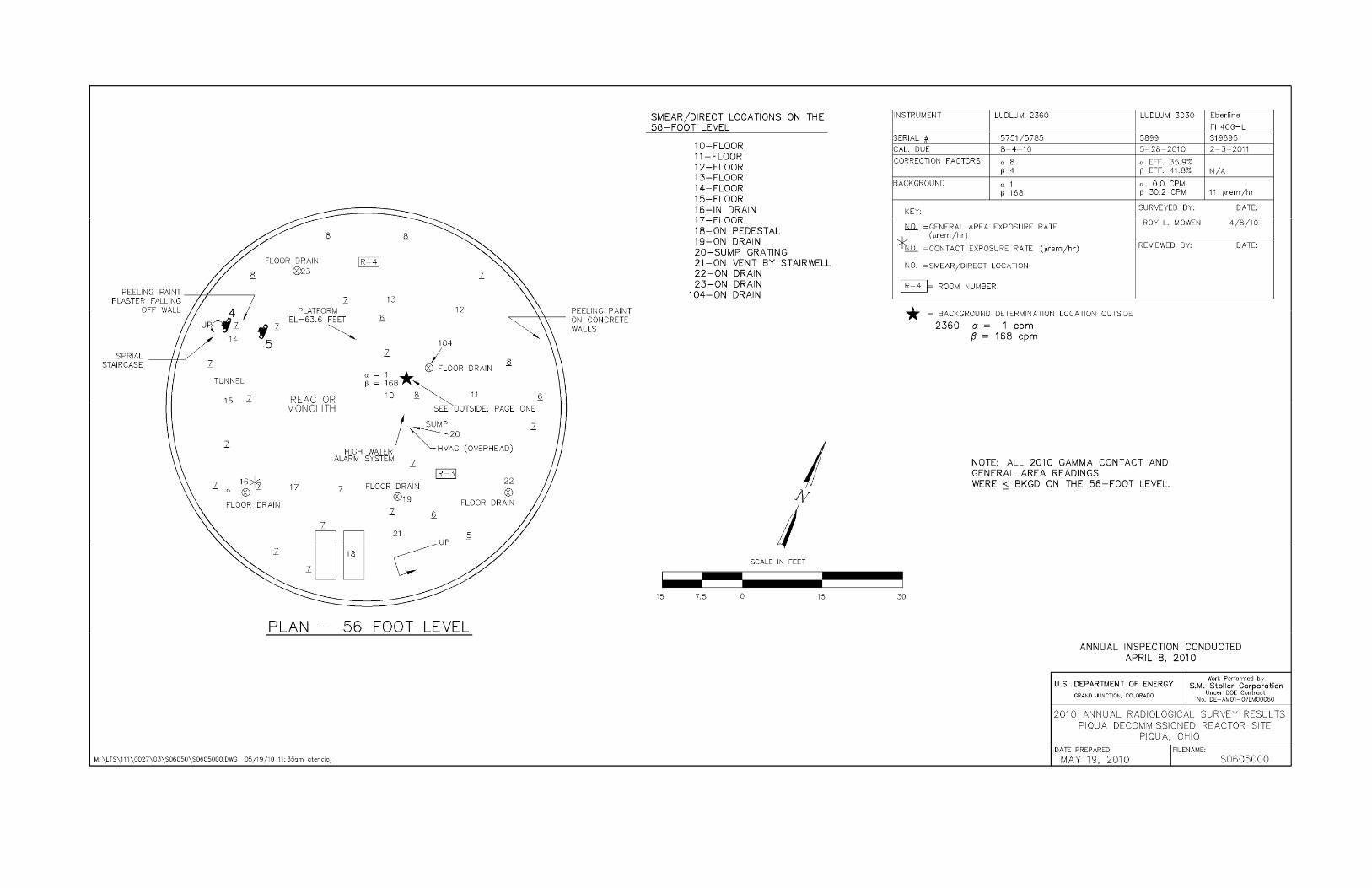
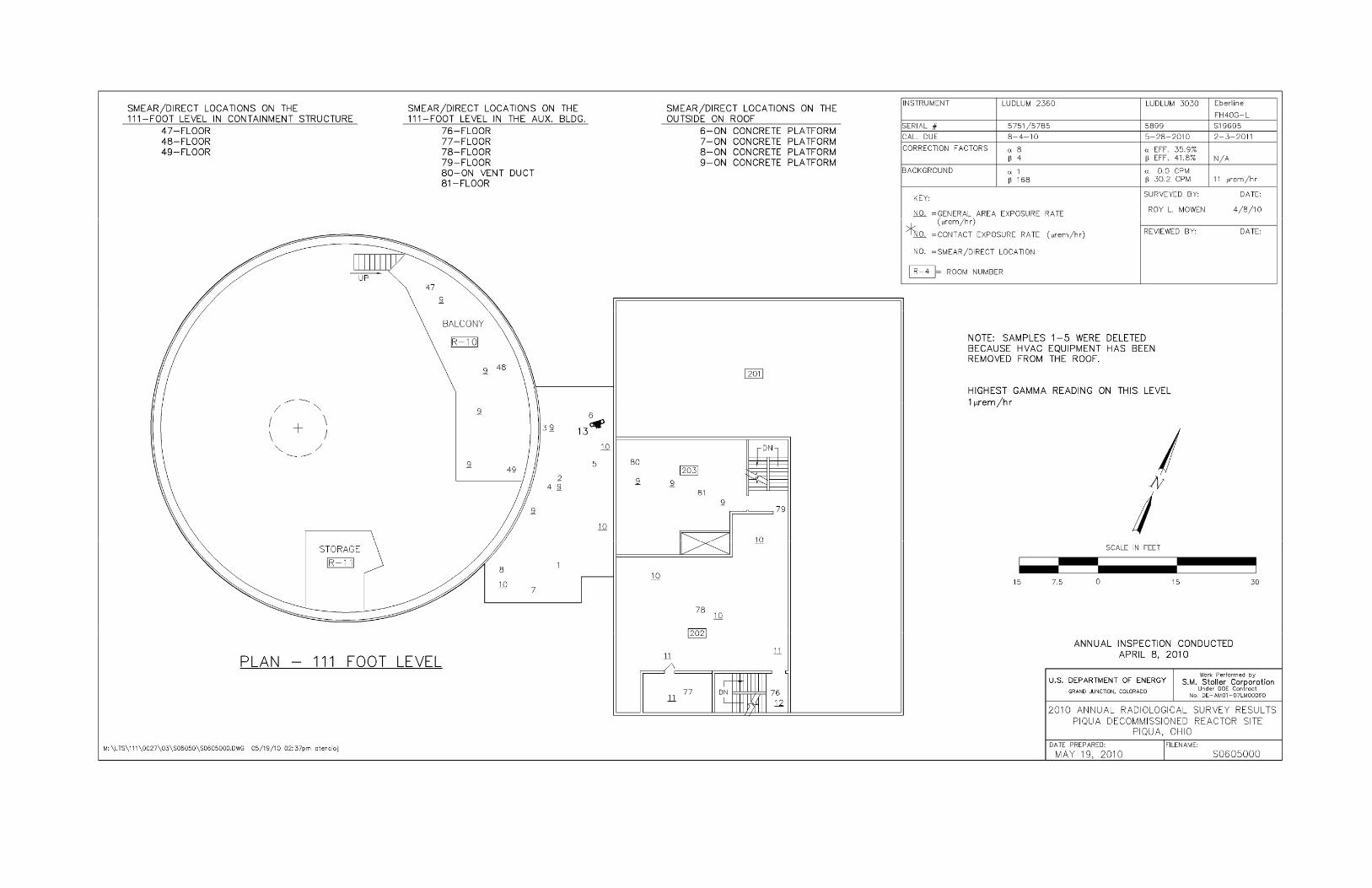
overflow, alerting personnel to both high water and possible sump pump failure. The alarm registers in the auxiliary building on the Supervisory Control and Data Acquisition system, which is monitored 24 hours a day by an operator. The alarm system is included in the monthly building inspection. The reactor sump alarm test log indicates that the alarm is being tested monthly. Water was present in the base of the sump during the inspection. 2.3 Radiological Survey S.M. Stoller staff performed the annual radiological survey on the interior of the reactor containment building, auxiliary building, and exterior areas. A total of 106 sample locations were investigated for both removable and surface contamination using direct measurements and smears for the detection of alpha and beta-gamma activity. Gamma exposure rates also were measured. Prior to 2008, 111 sample locations were surveyed. Locations 1–5 were removed from the survey in 2008 because the HVAC equipment being sampled was removed. PPS did some minor modifications to Rooms R–6 and R–7 in 2009, including the elimination of a connecting air duct between the two rooms. Smear sample #46 was collected from this air duct prior to 2009. Survey location #46 is now located on the floor of Room R–7 in front of the former air duct. PPS prefers to keep the door to Room 125 on the 100-foot level locked. Inspectors need to get the door unlocked to get radiation sample 109 and gamma readings from inside the room. Table 1 presents information on the instrumentation used to perform the survey. General area gamma exposure rates measured throughout the facility ranged from 5 to 13 μrem/hr.
Table 1. Instrumentation for Radiological Survey
Type of Measurement Radiation Detector Meter Background Correction
Factor
Minimum Detectable
Activity Surface Activity Alpha Ludlum 43–89
#5785 Ludlum 2360 #5751
1 cpm/100 cm² 8 alpha 31 dpm/ 100 cm²
Surface Activity Beta Ludlum 43–89 #5785
Ludlum 2360 #5751
168 cpm/100 cm²
4 beta 192 dpm/ 100 cm²
Exposure Rate Gamma N/A Eberline FH40 GL #S19695
11 μrem/hr N/A 1 μrem/hr
Removable Activity
Alpha N/A Ludlum 3030/ #5903
0.0 cpm Efficiency 35.9%
7.0 dpm/ 100 cm²
Removable Activity
Beta N/A Ludlum 3030/ #5903
30.2 cpm Efficiency 41.8%
86.0 dpm/ 100 cm²
Key: cpm = counts per minute; dpm = disintegrations per minute; cm2 = square centimeters; μrem/hr = microrem per hour
Table 2 presents direct surface and removable activity results. Direct surface measurement results indicate the floor drain at the lowest level of the containment building exhibited a direct beta activity of 2,400 disintegrations per minute per 100 square centimeters (dpm/100 cm2). The

U.S. Department of Energy 2010 Annual Inspection – Piqua, OH, Decommissioned Reactor Site June 2010 Page 5
smear from this location indicated that no removable activity is present. This result is consistent with previous surveys. All other direct measurements were below the MDA. No removable contamination was found at any of the 106 sampling points. Attached are the survey maps that indicate the location of each direct measurement and smear sample. The maps also indicate the results of the gamma exposure rate survey conducted at PNPF.
Table 2. Results of the 2010 Radiological Survey at the Piqua, Ohio, Decommissioned Reactor Site
Location/ Building Elevationa Direct/
Smear #
Direct Reading Activity
dpm/100 cm2
Alpha / Beta
Removable Activity
dpm/100 cm2
Alpha/Beta
Remarks
Outside 111 ft. 1 NA NA NA NA HVAC Equip. Removed Outside 111 ft. 2 NA NA NA NA HVAC Equip. Removed Outside 111 ft. 3 NA NA NA NA HVAC Equip. Removed Outside 111 ft. 4 NA NA NA NA HVAC Equip. Removed Outside 111 ft. 5 NA NA NA NA HVAC Equip. Removed Outside 111 ft. 6 <MDA <MDA <MDA <MDA On concrete platform Outside 111 ft. 7 <MDA <MDA <MDA <MDA On concrete platform Outside 111 ft. 8 <MDA <MDA <MDA <MDA On concrete platform Outside 100 ft. 9 <MDA <MDA <MDA <MDA On concrete platform
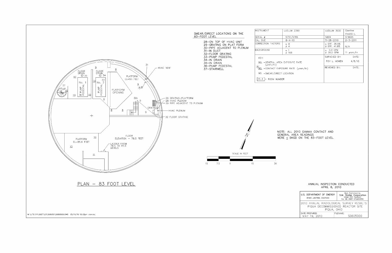
Containment 56 ft. 10 <MDA <MDA <MDA <MDA Floor Containment 56 ft. 11 <MDA <MDA <MDA <MDA Floor Containment 56 ft. 12 <MDA <MDA <MDA <MDA Floor Containment 56 ft. 13 <MDA <MDA <MDA <MDA Floor Containment 56 ft. 14 <MDA <MDA <MDA <MDA Floor Containment 56 ft. 15 <MDA <MDA <MDA <MDA Floor Containment 56 ft. 16 <MDA 2,400 <MDA <MDA In drain Containment 56 ft. 17 <MDA <MDA <MDA <MDA Floor Containment 56 ft. 18 <MDA <MDA <MDA <MDA On pedestal Containment 56 ft. 19 <MDA <MDA <MDA <MDA On drain Containment 56 ft. 20 <MDA <MDA <MDA <MDA On sump grating Containment 56 ft. 21 <MDA <MDA <MDA <MDA On vent by stairwell Containment 56 ft. 22 <MDA <MDA <MDA <MDA On drain Containment 56 ft. 23 <MDA <MDA <MDA <MDA On drain Containment 79 ft. 24 <MDA <MDA <MDA <MDA Floor Containment 79 ft. 25 <MDA <MDA <MDA <MDA Floor Containment 79 ft. 26 <MDA <MDA <MDA <MDA Floor Containment 79 ft. 27 <MDA <MDA <MDA <MDA Floor Containment 83 ft. 28 <MDA <MDA <MDA <MDA On top of HVAC duct Containment 83 ft. 29 <MDA <MDA <MDA <MDA Grating on platform Containment 83 ft. 30 <MDA <MDA <MDA <MDA Pipe adjacent to plenum Containment 83 ft. 31 <MDA <MDA <MDA <MDA In duct Containment 83 ft. 32 <MDA <MDA <MDA <MDA Floor grating Containment 83 ft. 33 <MDA <MDA <MDA <MDA Pump pedestal Containment 83 ft. 34 <MDA <MDA <MDA <MDA In drain Containment 83 ft. 35 <MDA <MDA <MDA <MDA In drain Containment 83 ft. 36 <MDA <MDA <MDA <MDA Pump pedestal Containment 83 ft. 37 <MDA <MDA <MDA <MDA Stairwell Containment 100 ft. 38 <MDA <MDA <MDA <MDA Floor Containment 100 ft. 39 <MDA <MDA <MDA <MDA Floor Containment 100 ft. 40 <MDA <MDA <MDA <MDA Floor Containment 100 ft. 41 <MDA <MDA <MDA <MDA Floor Containment 100 ft. 42 <MDA <MDA <MDA <MDA Floor Containment 100 ft. 43 <MDA <MDA <MDA <MDA Floor Containment 100 ft. 44 <MDA <MDA <MDA <MDA Floor Containment 100 ft. 45 <MDA <MDA <MDA <MDA On drain Containment 100 ft. 46 <MDA <MDA <MDA <MDA On floor of Room R–7

U.S. Department of Energy 2010 Annual Inspection – Piqua, OH, Decommissioned Reactor Site June 2010 Page 6
Location/ Building Elevationa Direct/
Smear #
Direct Reading Activity
dpm/100 cm2
Alpha / Beta
Removable Activity
dpm/100 cm2
Alpha/Beta
Remarks
Containment 111 ft. 47 <MDA <MDA <MDA <MDA Floor Containment 111 ft. 48 <MDA <MDA <MDA <MDA Floor Containment 111 ft. 49 <MDA <MDA <MDA <MDA Floor Containment 100 ft. 50 <MDA <MDA <MDA <MDA Airlock floor Aux. Bldg. 79 ft. 51 <MDA <MDA <MDA <MDA Floor Aux. Bldg. 79 ft. 52 <MDA <MDA <MDA <MDA Floor Aux. Bldg. 79 ft. 53 <MDA <MDA <MDA <MDA Floor Aux. Bldg. 79 ft. 54 <MDA <MDA <MDA <MDA On drain Aux. Bldg. 79 ft. 55 <MDA <MDA <MDA <MDA Floor Aux. Bldg. 79 ft. 56 <MDA <MDA <MDA <MDA Floor Aux. Bldg. 79 ft. 57 <MDA <MDA <MDA <MDA Floor Aux. Bldg. 79 ft. 58 <MDA <MDA <MDA <MDA On drain Aux. Bldg. 79 ft. 59 <MDA <MDA <MDA <MDA Floor Aux. Bldg. 79 ft. 60 <MDA <MDA <MDA <MDA Floor Aux. Bldg. 79 ft. 61 <MDA <MDA <MDA <MDA On drain Aux. Bldg. 79 ft. 62 <MDA <MDA <MDA <MDA On sump cover Aux. Bldg. 79 ft. 63 <MDA <MDA <MDA <MDA Pump Aux. Bldg. 79 ft. 64 <MDA <MDA <MDA <MDA Floor under tank Aux. Bldg. 79 ft. 65 <MDA <MDA <MDA <MDA Floor Aux. Bldg. 79 ft. 66 <MDA <MDA <MDA <MDA Floor Aux. Bldg. 79 ft. 67 <MDA <MDA <MDA <MDA Inside HVAC on floor Aux. Bldg. 79 ft. 68 <MDA <MDA <MDA <MDA Floor Aux. Bldg. 89 ft. 69 <MDA <MDA <MDA <MDA Floor Aux. Bldg. 121 ft. 70 <MDA <MDA <MDA <MDA Floor Aux. Bldg. 121 ft. 71 <MDA <MDA <MDA <MDA Floor Aux. Bldg. 121 ft. 72 <MDA <MDA <MDA <MDA Floor Aux. Bldg. 121 ft. 73 <MDA <MDA <MDA <MDA Floor Aux. Bldg. 121 ft. 74 <MDA <MDA <MDA <MDA Floor Aux. Bldg. 121 ft. 75 <MDA <MDA <MDA <MDA Floor Aux. Bldg. 111 ft. 76 <MDA <MDA <MDA <MDA Floor Aux. Bldg. 111 ft. 77 <MDA <MDA <MDA <MDA Floor Aux. Bldg. 111 ft. 78 <MDA <MDA <MDA <MDA Floor Aux. Bldg. 111 ft. 79 <MDA <MDA <MDA <MDA Floor Aux. Bldg. 111 ft. 80 <MDA <MDA <MDA <MDA On vent duct Aux. Bldg. 111 ft. 81 <MDA <MDA <MDA <MDA Floor Aux. Bldg. 100 ft. 82 <MDA <MDA <MDA <MDA Floor Aux. Bldg. 100 ft. 83 <MDA <MDA <MDA <MDA Floor Aux. Bldg. 100 ft. 84 <MDA <MDA <MDA <MDA Floor Aux. Bldg. 100 ft. 85 <MDA <MDA <MDA <MDA Floor Aux. Bldg. 100 ft. 86 <MDA <MDA <MDA <MDA On floor drain Aux. Bldg. 100 ft. 87 <MDA <MDA <MDA <MDA Floor Aux. Bldg. 100 ft. 88 <MDA <MDA <MDA <MDA On floor drain Aux. Bldg. 100 ft. 89 <MDA <MDA <MDA <MDA Floor Aux. Bldg. 100 ft. 90 <MDA <MDA <MDA <MDA Floor Aux. Bldg. 100 ft. 91 <MDA <MDA <MDA <MDA Floor Aux. Bldg. 100 ft. 92 <MDA <MDA <MDA <MDA Floor Aux. Bldg. 100 ft. 93 <MDA <MDA <MDA <MDA Floor Aux. Bldg. 100 ft. 94 <MDA <MDA <MDA <MDA Floor Aux. Bldg. 100 ft. 95 <MDA <MDA <MDA <MDA Floor Aux. Bldg. 100 ft. 96 <MDA <MDA <MDA <MDA Floor Aux. Bldg. 100 ft. 97 <MDA <MDA <MDA <MDA Floor Aux. Bldg. 100 ft. 98 <MDA <MDA <MDA <MDA Floor Aux. Bldg. 100 ft. 99 <MDA <MDA <MDA <MDA Floor Aux. Bldg. 100 ft. 100 <MDA <MDA <MDA <MDA Floor Aux. Bldg. 100 ft. 101 <MDA <MDA <MDA <MDA Floor Aux. Bldg. 100 ft. 102 <MDA <MDA <MDA <MDA Floor Aux. Bldg. 100 ft. 103 <MDA <MDA <MDA <MDA Floor
U.S. Department of Energy 2010 Annual Inspection – Piqua, OH, Decommissioned Reactor Site June 2010 Page 7
Location/ Building Elevationa Direct/
Smear #
Direct Reading Activity
dpm/100 cm2
Alpha / Beta
Removable Activity
dpm/100 cm2
Alpha/Beta
Remarks
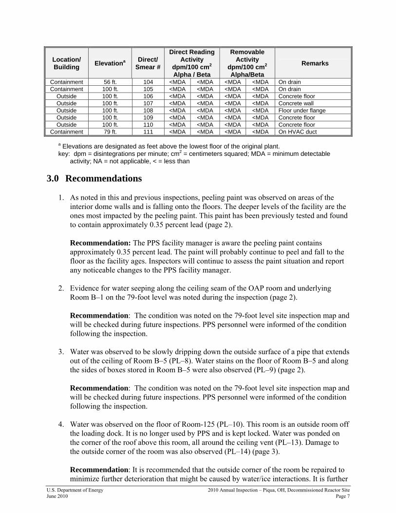
Containment 56 ft. 104 <MDA <MDA <MDA <MDA On drain Containment 100 ft. 105 <MDA <MDA <MDA <MDA On drain
Outside 100 ft. 106 <MDA <MDA <MDA <MDA Concrete floor Outside 100 ft. 107 <MDA <MDA <MDA <MDA Concrete wall Outside 100 ft. 108 <MDA <MDA <MDA <MDA Floor under flange Outside 100 ft. 109 <MDA <MDA <MDA <MDA Concrete floor Outside 100 ft. 110 <MDA <MDA <MDA <MDA Concrete floor
Containment 79 ft. 111 <MDA <MDA <MDA <MDA On HVAC duct
a Elevations are designated as feet above the lowest floor of the original plant. key: dpm = disintegrations per minute; cm2 = centimeters squared; MDA = minimum detectable
activity; NA = not applicable, < = less than 3.0 Recommendations
1. As noted in this and previous inspections, peeling paint was observed on areas of the interior dome walls and is falling onto the floors. The deeper levels of the facility are the ones most impacted by the peeling paint. This paint has been previously tested and found to contain approximately 0.35 percent lead (page 2).
Recommendation: The PPS facility manager is aware the peeling paint contains approximately 0.35 percent lead. The paint will probably continue to peel and fall to the floor as the facility ages. Inspectors will continue to assess the paint situation and report any noticeable changes to the PPS facility manager.
2. Evidence for water seeping along the ceiling seam of the OAP room and underlying
Room B–1 on the 79-foot level was noted during the inspection (page 2).
Recommendation: The condition was noted on the 79-foot level site inspection map and will be checked during future inspections. PPS personnel were informed of the condition following the inspection.
3. Water was observed to be slowly dripping down the outside surface of a pipe that extends
out of the ceiling of Room B–5 (PL–8). Water stains on the floor of Room B–5 and along the sides of boxes stored in Room B–5 were also observed (PL–9) (page 2).
Recommendation: The condition was noted on the 79-foot level site inspection map and will be checked during future inspections. PPS personnel were informed of the condition following the inspection.
4. Water was observed on the floor of Room-125 (PL–10). This room is an outside room off
the loading dock. It is no longer used by PPS and is kept locked. Water was ponded on the corner of the roof above this room, all around the ceiling vent (PL–13). Damage to the outside corner of the room was also observed (PL–14) (page 3).
Recommendation: It is recommended that the outside corner of the room be repaired to minimize further deterioration that might be caused by water/ice interactions. It is further
U.S. Department of Energy 2010 Annual Inspection – Piqua, OH, Decommissioned Reactor Site June 2010 Page 8
recommended that the reason why water is ponding and not properly draining from the corner of the roof above Room-125 be determined and corrected. PPS personnel were informed of the condition following the inspection.
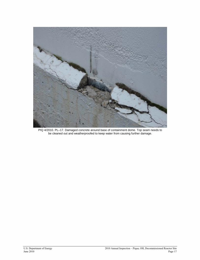
5. The concrete around the base of the outside wall of the containment structure is cracking
in several places (PL–15, PL–16, and PL–17). The cracks are allowing water to enter, freeze and expand, and further damage the concrete (page 3).
Recommendation: It is recommended that the cracks be repaired and any damaged concrete areas be patched while the damage is still minor to avoid larger problems and repair costs in the future. PPS personnel were informed of the condition following the inspection.
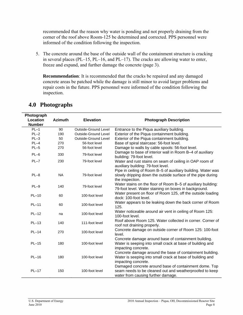
4.0 Photographs
Photograph Location Number
Azimuth
Elevation
Photograph Description
PL–1 90 Outside-Ground Level Entrance to the Piqua auxiliary building. PL–2 190 Outside-Ground Level Exterior of the Piqua containment building. PL–3 50 Outside-Ground Level Exterior of the Piqua containment building. PL–4 270 56-foot level Base of spiral staircase: 56-foot level. PL–5 270 56-foot level Damage to walls by cable spools: 56-foot level.
PL–6 330 79-foot level Damage to base of interior wall in Room B–4 of auxiliary building: 79-foot level.
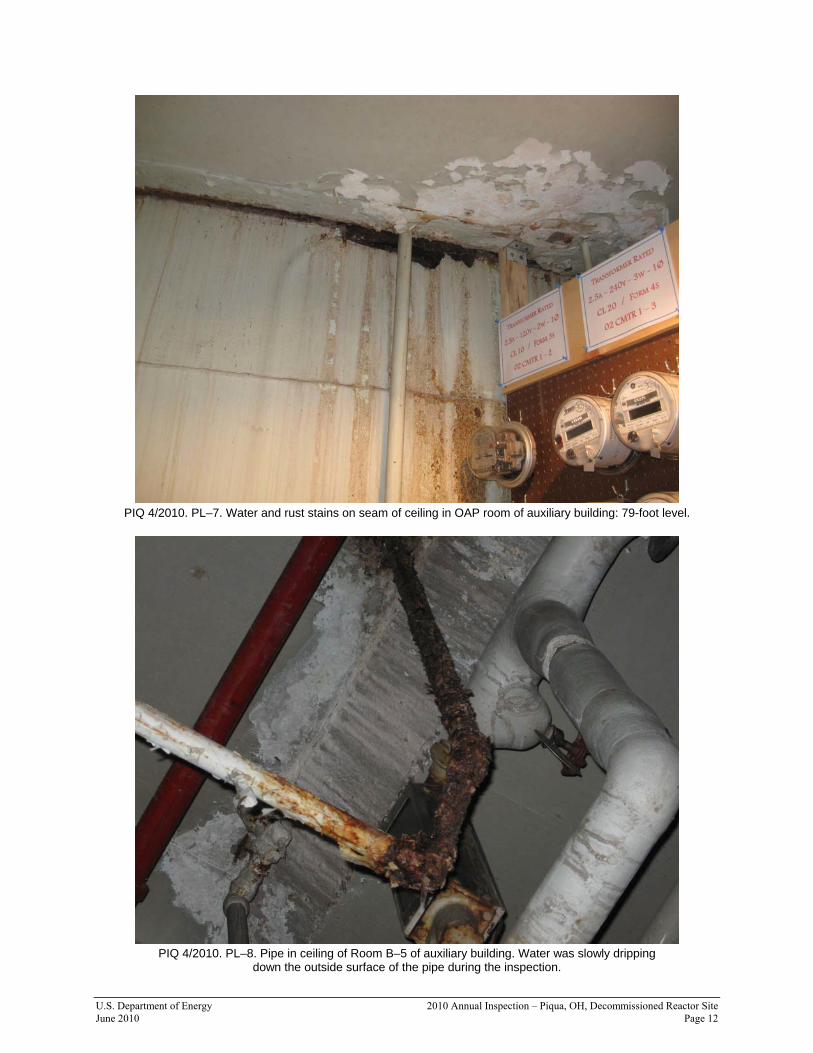
PL–7 230 79-foot level Water and rust stains on seam of ceiling in OAP room of auxiliary building: 79-foot level.
PL–8 NA 79-foot level Pipe in ceiling of Room B–5 of auxiliary building. Water was slowly dripping down the outside surface of the pipe during the inspection.
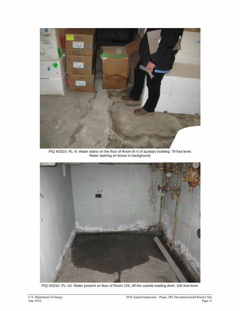
PL–9 140 79-foot level Water stains on the floor of Room B–5 of auxiliary building: 79-foot level. Water staining on boxes in background.
PL–10 60 100-foot level Water present on floor of Room 125, off the outside loading dock: 100-foot level.
PL–11 60 100-foot level Water appears to be leaking down the back corner of Room 125.
PL–12 na 100-foot level Water noticeable around air vent in ceiling of Room 125: 100-foot level.
PL–13 140 111-foot level Roof above Room 125. Water collected in corner. Corner of roof not draining properly.
PL–14 270 100-foot level Concrete damage on outside corner of Room 125: 100-foot level.
PL–15 180 100-foot level Concrete damage around base of containment building. Water is seeping into small crack at base of building and impacting concrete.
PL–16 180 100-foot level Concrete damage around the base of containment building. Water is seeping into small crack at base of building and impacting concrete.
PL–17 150 100-foot level Damaged concrete around base of containment dome. Top seam needs to be cleaned out and weatherproofed to keep water from causing further damage.

U.S. Department of Energy 2010 Annual Inspection – Piqua, OH, Decommissioned Reactor Site June 2010 Page 9
PIQ 4/2010. PL–1. Entrance to the Piqua auxiliary building.
PIQ 4/2010. PL–2. Exterior of the Piqua containment building.

U.S. Department of Energy 2010 Annual Inspection – Piqua, OH, Decommissioned Reactor Site June 2010 Page 10
PIQ 4/2010. PL–3. Exterior of the Piqua containment building.
PIQ 4/2010. PL–4. Base of spiral staircase: 56-foot level.
U.S. Department of Energy 2010 Annual Inspection – Piqua, OH, Decommissioned Reactor Site June 2010 Page 11
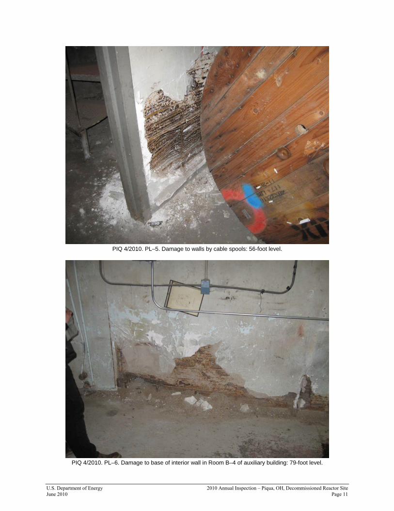
PIQ 4/2010. PL–5. Damage to walls by cable spools: 56-foot level.
PIQ 4/2010. PL–6. Damage to base of interior wall in Room B–4 of auxiliary building: 79-foot level.
U.S. Department of Energy 2010 Annual Inspection – Piqua, OH, Decommissioned Reactor Site June 2010 Page 12
PIQ 4/2010. PL–7. Water and rust stains on seam of ceiling in OAP room of auxiliary building: 79-foot level.
PIQ 4/2010. PL–8. Pipe in ceiling of Room B–5 of auxiliary building. Water was slowly dripping
down the outside surface of the pipe during the inspection.
U.S. Department of Energy 2010 Annual Inspection – Piqua, OH, Decommissioned Reactor Site June 2010 Page 13
PIQ 4/2010. PL–9. Water stains on the floor of Room B–5 of auxiliary building: 79-foot level.
Water staining on boxes in background.
PIQ 4/2010. PL–10. Water present on floor of Room 125, off the outside loading dock: 100-foot level.

U.S. Department of Energy 2010 Annual Inspection – Piqua, OH, Decommissioned Reactor Site June 2010 Page 14
PIQ 4/2010. PL–11. Water appears to be leaking down the back corner of Room 125.
PIQ 4/2010. PL–12. Water noticeable around air vent in ceiling of Room 125: 100-foot level.

U.S. Department of Energy 2010 Annual Inspection – Piqua, OH, Decommissioned Reactor Site June 2010 Page 15
PIQ 4/2010. PL–13. Roof above Room 125. Water collected in corner. Corner of roof not draining properly.
PIQ 4/2010. PL–14. Concrete damage on outside corner of Room 125: 100-foot level.

U.S. Department of Energy 2010 Annual Inspection – Piqua, OH, Decommissioned Reactor Site June 2010 Page 16
PIQ 4/2010. PL–15. Concrete damage around base of containment building. Water is
seeping into small crack at base of building and impacting concrete.
PIQ 4/2010. PL–16. Concrete damage around the base of containment building. Water is
seeping into small crack at base of building and impacting concrete.
U.S. Department of Energy 2010 Annual Inspection – Piqua, OH, Decommissioned Reactor Site June 2010 Page 17
PIQ 4/2010. PL–17. Damaged concrete around base of containment dome. Top seam needs to
be cleaned out and weatherproofed to keep water from causing further damage.