Embed Size (px)
Citation preview
USER GUIDE
2O1O Patriot

IMPORTANT: This User Guide is intended to familiarize you with the important features of your vehicle. The DVD enclosed contains your Owner’s Manual, Navigation Radio or Multimedia Radio Manual, Warranty Booklets, Tire Warranty and 24-Hour Towing Assistance (new vehicles purchased in the U.S.) or Roadside Assistance (new vehicles purchased in Canada) in electronic format. We hope you find it useful. If you are the first registered owner of your vehicle, you may obtain a printed copy of the Owner’s Manual, Navigation Radio or Multimedia Radio Manual or Warranty Booklet by calling 1-800-992-1997 (U.S.) or 1-800-387-1143 (Canada) or by contacting your dealer. Replacement manuals may be purchased by visiting www.techauthority.com. Jeep® is a registered trademark of Chrysler Group LLC. Copyright © 2009 Chrysler Group LLC.
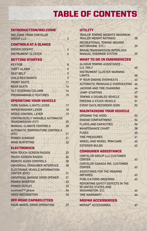
INTRODUCTION/WELCOME
WELCOME FROM CHRYSLERGROUP LLC . . . . . . . . . . . . . . . . . 2
CONTROLS AT A GLANCE
DRIVER COCKPIT . . . . . . . . . . . . . . 4INSTRUMENT CLUSTER . . . . . . . . . . 6
GETTING STARTED
KEY FOB . . . . . . . . . . . . . . . . . . 8THEFT ALARM . . . . . . . . . . . . . . . 9SEAT BELT . . . . . . . . . . . . . . . . . 9CHILD RESTRAINTS . . . . . . . . . . . . 9FRONT SEATS . . . . . . . . . . . . . . . 11REAR SEATS . . . . . . . . . . . . . . . . 14TILT STEERING COLUMN . . . . . . . . . 14PROGRAMMABLE FEATURES . . . . . . . 15
OPERATING YOUR VEHICLETURN SIGNAL/LIGHTS LEVER . . . . . . . 17WIPER/WASHER LEVER . . . . . . . . . . 18SPEED CONTROL LEVER . . . . . . . . . 19CONTINUOUSLY VARIABLE AUTOMATICTRANSMISSION (CVT) . . . . . . . . . . . 20MANUAL CLIMATE CONTROLS . . . . . . 20AUTOMATIC TEMPERATURE CONTROLS(ATC) . . . . . . . . . . . . . . . . . . . . 21POWER SUNROOF . . . . . . . . . . . . . 21WIND BUFFETING . . . . . . . . . . . . . 22
ELECTRONICSNON-TOUCH-SCREEN RADIOS . . . . . . 23TOUCH-SCREEN RADIOS . . . . . . . . . 26REMOTE AUDIO CONTROLS . . . . . . . . 30UNIVERSAL CONSUMER INTERFACE . . . 30ELECTRONIC VEHICLE INFORMATIONCENTER (EVIC) . . . . . . . . . . . . . . . 31UNIVERSAL GARAGE DOOR OPENER . . . 31POWER INVERTER . . . . . . . . . . . . . 33POWER OUTLET . . . . . . . . . . . . . . 33uconnect™ phone . . . . . . . . . . . . . 34VOICE RECOGNITION . . . . . . . . . . . . 36
OFF-ROAD CAPABILITIESFOUR-WHEEL DRIVE OPERATION . . . . . 37
UTILITYTRAILER TOWING WEIGHTS (MAXIMUMTRAILER WEIGHT RATINGS) . . . . . . . . 38RECREATIONAL TOWING (BEHINDMOTORHOME, ETC.) . . . . . . . . . . . . 39BRAKE/TRANSMISSION INTERLOCKMANUAL OVERRIDE SYSTEM . . . . . . . 39
WHAT TO DO IN EMERGENCIES24 HOUR TOWING ASSISTANCE -U.S. ONLY . . . . . . . . . . . . . . . . . . 40INSTRUMENT CLUSTER WARNINGLIGHTS . . . . . . . . . . . . . . . . . . . 40IF YOUR ENGINE OVERHEATS . . . . . . . 43AUTOMATIC TRANSAXLE OVERHEATING . 44JACKING AND TIRE CHANGING . . . . . . 44JUMP-STARTING . . . . . . . . . . . . . . 47TOWING A DISABLED VEHICLE . . . . . . 50FREEING A STUCK VEHICLE . . . . . . . . 51EVENT DATA RECORDER (EDR) . . . . . . 52
MAINTAINING YOUR VEHICLEOPENING THE HOOD . . . . . . . . . . . . 53ENGINE COMPARTMENT . . . . . . . . . 54FLUIDS AND CAPACITIES . . . . . . . . . 56MAINTENANCE CHART . . . . . . . . . . 58FUSES . . . . . . . . . . . . . . . . . . . 60TIRE PRESSURES . . . . . . . . . . . . . 61WHEEL AND WHEEL TRIM CARE . . . . . 62EXTERIOR BULBS . . . . . . . . . . . . . 62
CONSUMER ASSISTANCECHRYSLER GROUP LLC CUSTOMERCENTER . . . . . . . . . . . . . . . . . . . 63CHRYSLER CANADA INC. CUSTOMERCENTER . . . . . . . . . . . . . . . . . . . 63ASSISTANCE FOR THE HEARINGIMPAIRED . . . . . . . . . . . . . . . . . . 63PUBLICATIONS ORDERING . . . . . . . . 63REPORTING SAFETY DEFECTS IN THE50 UNITED STATES ANDWASHINGTON, D.C. . . . . . . . . . . . . 64TIRE WARRANTY . . . . . . . . . . . . . . 64
MOPAR ACCESSORIESMOPAR® ACCESSORIES . . . . . . . . . . 67
TABLE OF CONTENTS
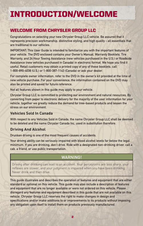
WELCOME FROM CHRYSLER GROUP LLCCongratulations on selecting your new Chrysler Group LLC vehicle. Be assured that itrepresents precision workmanship, distinctive styling, and high quality - all essentials thatare traditional to our vehicles.
IMPORTANT: This User Guide is intended to familiarize you with the important features ofyour vehicle. The DVD enclosed contains your Owner’s Manual, Warranty Booklets, TireWarranty, and 24 Hour Towing Assistance (new vehicles purchased in the U.S.) or RoadsideAssistance (new vehicles purchased in Canada) in electronic format. We hope you find ituseful. Retail customers may obtain a printed copy of any of these booklets, call1-800-890-4038 (U.S.) or 1-800-387-1143 (Canada) or ask your dealer.
For complete owner information, refer to the DVD in the owner’s kit provided at the time ofnew vehicle purchase. For your convenience, the information contained on the DVD mayalso be printed and saved for future reference.
Not all features shown in this guide may apply to your vehicle.
Chrysler Group LLC is committed to protecting our environment and natural resources. Byconverting from paper to electronic delivery for the majority of the user information for yourvehicle, together we greatly reduce the demand for tree-based products and lessen thestress on our environment.
Vehicles Sold In CanadaWith respect to any Vehicles Sold in Canada, the name Chrysler Group LLC shall be deemedto be deleted and the name Chrysler Canada Inc. used in substitution therefore.
Driving And AlcoholDrunken driving is one of the most frequent causes of accidents.
Your driving ability can be seriously impaired with blood alcohol levels far below the legalminimum. If you are drinking, don’t drive. Ride with a designated non-drinking driver, call acab, a friend, or use public transportation.
WARNING!
Driving after drinking can lead to an accident. Your perceptions are less sharp, yourreflexes are slower, and your judgment is impaired when you have been drinking.Never drink and then drive.
This guide illustrates and describes the operation of features and equipment that are eitherstandard or optional on this vehicle. This guide may also include a description of featuresand equipment that are no longer available or were not ordered on this vehicle. Pleasedisregard any features and equipment described in this guide that are not available on thisvehicle. Chrysler Group LLC reserves the right to make changes in design andspecifications and/or make additions to or improvements to its products without imposingany obligation upon itself to install them on products previously manufactured.
INTRODUCTION/WELCOME
2
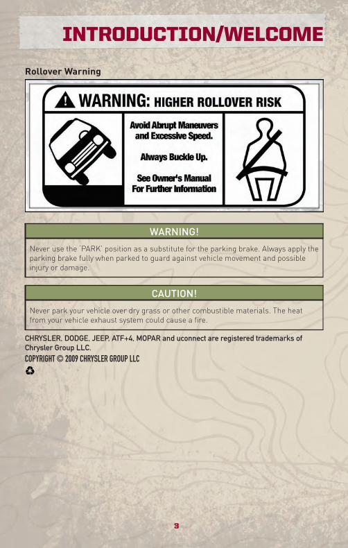
Rollover Warning
WARNING!
Never use the ‘PARK’ position as a substitute for the parking brake. Always apply theparking brake fully when parked to guard against vehicle movement and possibleinjury or damage.
CAUTION!
Never park your vehicle over dry grass or other combustible materials. The heatfrom your vehicle exhaust system could cause a fire.
CHRYSLER, DODGE, JEEP, ATF+4, MOPAR and uconnect are registered trademarks ofChrysler Group LLC.COPYRIGHT © 2009 CHRYSLER GROUP LLC
3
INTRODUCTION/WELCOME
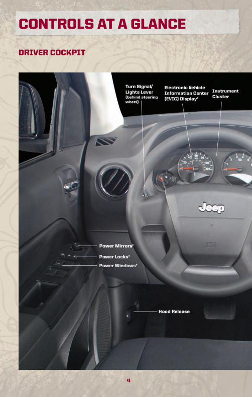
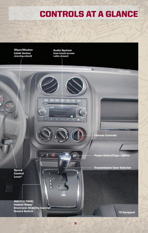
DRIVER COCKPIT
4
CONTROLS AT A GLANCE
5
CONTROLS AT A GLANCE
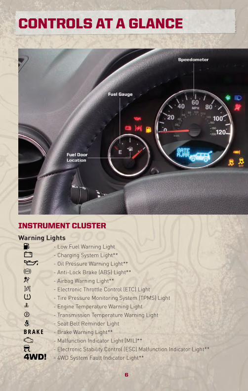
INSTRUMENT CLUSTER
Warning Lights- Low Fuel Warning Light
- Charging System Light**
- Oil Pressure Warning Light**
- Anti-Lock Brake (ABS) Light**
- Airbag Warning Light**
- Electronic Throttle Control (ETC) Light
- Tire Pressure Monitoring System (TPMS) Light
- Engine Temperature Warning Light
- Transmission Temperature Warning Light
- Seat Belt Reminder Light
BRAKE - Brake Warning Light**
- Malfunction Indicator Light (MIL)**
- Electronic Stability Control (ESC) Malfunction Indicator Light**
- 4WD System Fault Indicator Light**
6
CONTROLS AT A GLANCE
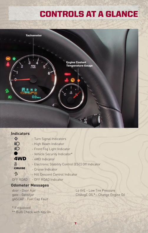
Indicators- Turn Signal Indicators
- High Beam Indicator
- Front Fog Light Indicator
- Vehicle Security Indicator*
- 4WD Indicator
- Electronic Stability Control (ESC) Off Indicator
- Cruise Indicator
- Hill Descent Control Indicator
OFF ROAD - OFF ROAD Indicator
Odometer Messagesdoor - Door Ajar Lo tIrE - Low Tire Pressuregate - GateAjar CHAngE OIL* - Change Engine OilgASCAP - Fuel Cap Fault
* If equipped** Bulb Check with Key On
7
CONTROLS AT A GLANCE
KEY FOB
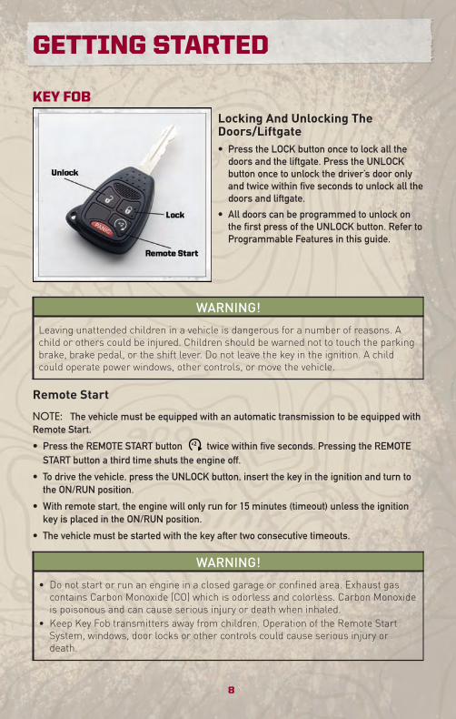
Locking And Unlocking TheDoors/Liftgate• Press the LOCK button once to lock all the
doors and the liftgate. Press the UNLOCKbutton once to unlock the driver’s door onlyand twice within five seconds to unlock all thedoors and liftgate.
• All doors can be programmed to unlock onthe first press of the UNLOCK button. Refer toProgrammable Features in this guide.
WARNING!
Leaving unattended children in a vehicle is dangerous for a number of reasons. Achild or others could be injured. Children should be warned not to touch the parkingbrake, brake pedal, or the shift lever. Do not leave the key in the ignition. A childcould operate power windows, other controls, or move the vehicle.
Remote Start
NOTE: The vehicle must be equipped with an automatic transmission to be equipped withRemote Start.
• Press the REMOTE START button x2 twice within five seconds. Pressing the REMOTESTART button a third time shuts the engine off.
• To drive the vehicle, press the UNLOCK button, insert the key in the ignition and turn tothe ON/RUN position.
• With remote start, the engine will only run for 15 minutes (timeout) unless the ignitionkey is placed in the ON/RUN position.
• The vehicle must be started with the key after two consecutive timeouts.
WARNING!
• Do not start or run an engine in a closed garage or confined area. Exhaust gascontains Carbon Monoxide (CO) which is odorless and colorless. Carbon Monoxideis poisonous and can cause serious injury or death when inhaled.
• Keep Key Fob transmitters away from children. Operation of the Remote StartSystem, windows, door locks or other controls could cause serious injury ordeath.
GETTING STARTED
8
Panic Alarm• Press the PANIC button once to turn the panic alarm on.
• Wait approximately three seconds and press the button a second time to turn the panicalarm off.
THEFT ALARM
To Arm• Press the Key Fob LOCK button or the power door lock switch while the door is open.
To Disarm• Press the Key Fob UNLOCK button or turn the ignition to the ON position.
SEAT BELT• Be sure everyone in your vehicle is in a seat using a seat belt properly.
WARNING!
In a collision, you and your passengers can suffer much greater injuries if you arenot properly buckled up. You can strike the interior of your vehicle or otherpassengers, or you can be thrown out of the vehicle. Always be sure you and othersin your vehicle are buckled up properly.
CHILD RESTRAINTS• Every state in the United States and all Canadian provinces require that small children
ride in proper restraint systems. This is the law, and you can be prosecuted for ignoring it.
WARNING!
In a collision, an unrestrained child, even a tiny baby, can become a projectile insidethe vehicle. The force required to hold even an infant on your lap could become sogreat that you could not hold the child, no matter how strong you are. The child andothers could be badly injured. Any child riding in your vehicle should be in a properrestraint for the child’s size.
Installing The LATCH-Compatible Child Restraint System• Your vehicle's second row passenger seats are equipped with the child restraint
anchorage system called LATCH, which stands for Lower Anchors and Tether forCHildren. LATCH child restraint anchorage systems are installed at all three rear seatingpositions.
• All three rear seating positions can accommodate LATCH-compatible child seats havingflexible, webbing-mounted lower attachments.
9
GETTING STARTED
• Child seats with fixed lower attachments must be installed in the outboard positions only.
• NEVER install LATCH-compatible child seats such that two seats share a common loweranchorage.
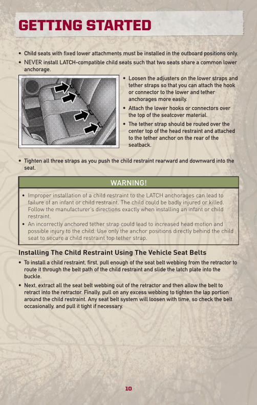
• Loosen the adjusters on the lower straps andtether straps so that you can attach the hookor connector to the lower and tetheranchorages more easily.
• Attach the lower hooks or connectors overthe top of the seatcover material.
• The tether strap should be routed over thecenter top of the head restraint and attachedto the tether anchor on the rear of theseatback.
• Tighten all three straps as you push the child restraint rearward and downward into theseat.
WARNING!
• Improper installation of a child restraint to the LATCH anchorages can lead tofailure of an infant or child restraint. The child could be badly injured or killed.Follow the manufacturer’s directions exactly when installing an infant or childrestraint.
• An incorrectly anchored tether strap could lead to increased head motion andpossible injury to the child. Use only the anchor positions directly behind the childseat to secure a child restraint top tether strap.
Installing The Child Restraint Using The Vehicle Seat Belts• To install a child restraint, first, pull enough of the seat belt webbing from the retractor to
route it through the belt path of the child restraint and slide the latch plate into thebuckle.
• Next, extract all the seat belt webbing out of the retractor and then allow the belt toretract into the retractor. Finally, pull on any excess webbing to tighten the lap portionaround the child restraint. Any seat belt system will loosen with time, so check the beltoccasionally, and pull it tight if necessary.
GETTING STARTED
10
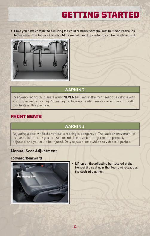
• Once you have completed securing the child restraint with the seat belt, secure the toptether strap. The tether strap should be routed over the center top of the head restraint.
WARNING!
Rearward-facing child seats must NEVER be used in the front seat of a vehicle witha front passenger airbag. An airbag deployment could cause severe injury or deathto infants in this position.
FRONT SEATS
WARNING!
Adjusting a seat while the vehicle is moving is dangerous. The sudden movement ofthe seat could cause you to lose control. The seat belt might not be properlyadjusted, and you could be injured. Only adjust a seat while the vehicle is parked.
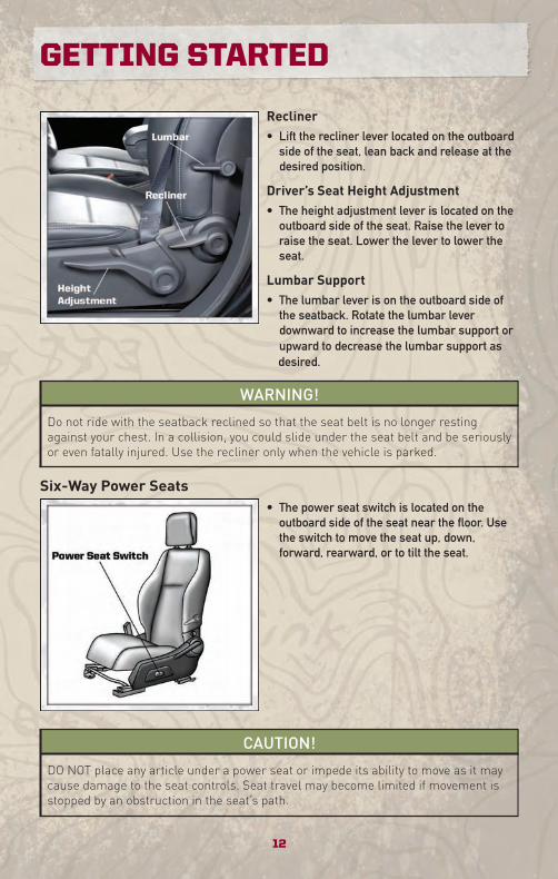
Manual Seat Adjustment
Forward/Rearward• Lift up on the adjusting bar located at the
front of the seat near the floor and release atthe desired position.
11
GETTING STARTED
Recliner• Lift the recliner lever located on the outboard
side of the seat, lean back and release at thedesired position.
Driver’s Seat Height Adjustment• The height adjustment lever is located on the
outboard side of the seat. Raise the lever toraise the seat. Lower the lever to lower theseat.
Lumbar Support• The lumbar lever is on the outboard side of
the seatback. Rotate the lumbar leverdownward to increase the lumbar support orupward to decrease the lumbar support asdesired.
WARNING!
Do not ride with the seatback reclined so that the seat belt is no longer restingagainst your chest. In a collision, you could slide under the seat belt and be seriouslyor even fatally injured. Use the recliner only when the vehicle is parked.
Six-Way Power Seats• The power seat switch is located on the
outboard side of the seat near the floor. Usethe switch to move the seat up, down,forward, rearward, or to tilt the seat.
CAUTION!
DO NOT place any article under a power seat or impede its ability to move as it maycause damage to the seat controls. Seat travel may become limited if movement isstopped by an obstruction in the seat’s path.
GETTING STARTED
12
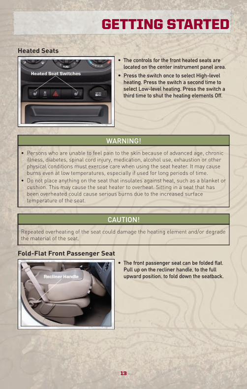
Heated Seats• The controls for the front heated seats are
located on the center instrument panel area.
• Press the switch once to select High-levelheating. Press the switch a second time toselect Low-level heating. Press the switch athird time to shut the heating elements Off.
WARNING!
• Persons who are unable to feel pain to the skin because of advanced age, chronicillness, diabetes, spinal cord injury, medication, alcohol use, exhaustion or otherphysical conditions must exercise care when using the seat heater. It may causeburns even at low temperatures, especially if used for long periods of time.
• Do not place anything on the seat that insulates against heat, such as a blanket orcushion. This may cause the seat heater to overheat. Sitting in a seat that hasbeen overheated could cause serious burns due to the increased surfacetemperature of the seat.
CAUTION!
Repeated overheating of the seat could damage the heating element and/or degradethe material of the seat.
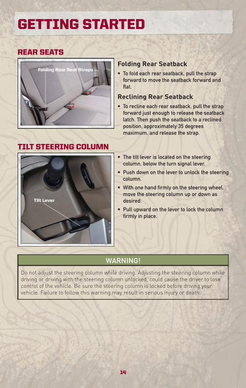
Fold-Flat Front Passenger Seat• The front passenger seat can be folded flat.
Pull up on the recliner handle, to the fullupward position, to fold down the seatback.
13
GETTING STARTED
REAR SEATS
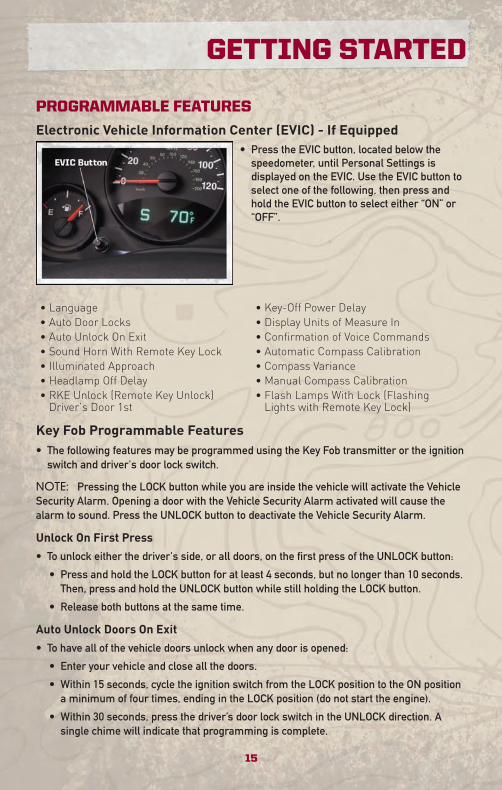
Folding Rear Seatback• To fold each rear seatback, pull the strap
forward to move the seatback forward andflat.
Reclining Rear Seatback• To recline each rear seatback, pull the strap
forward just enough to release the seatbacklatch. Then push the seatback to a reclinedposition, approximately 35 degreesmaximum, and release the strap.
TILT STEERING COLUMN• The tilt lever is located on the steering
column, below the turn signal lever.
• Push down on the lever to unlock the steeringcolumn.
• With one hand firmly on the steering wheel,move the steering column up or down asdesired.
• Pull upward on the lever to lock the columnfirmly in place.
WARNING!
Do not adjust the steering column while driving. Adjusting the steering column whiledriving or driving with the steering column unlocked, could cause the driver to losecontrol of the vehicle. Be sure the steering column is locked before driving yourvehicle. Failure to follow this warning may result in serious injury or death.
GETTING STARTED
14
PROGRAMMABLE FEATURES
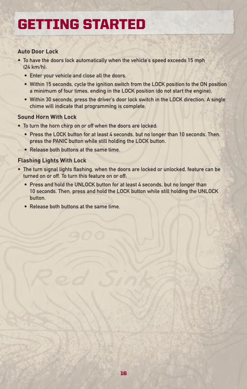
Electronic Vehicle Information Center (EVIC) - If Equipped• Press the EVIC button, located below the
speedometer, until Personal Settings isdisplayed on the EVIC. Use the EVIC button toselect one of the following, then press andhold the EVIC button to select either “ON” or“OFF”.
• Language • Key-Off Power Delay• Auto Door Locks • Display Units of Measure In• Auto Unlock On Exit • Confirmation of Voice Commands• Sound Horn With Remote Key Lock • Automatic Compass Calibration• Illuminated Approach • Compass Variance• Headlamp Off Delay • Manual Compass Calibration• RKE Unlock (Remote Key Unlock)Driver’s Door 1st
• Flash Lamps With Lock (FlashingLights with Remote Key Lock)
Key Fob Programmable Features• The following features may be programmed using the Key Fob transmitter or the ignition
switch and driver's door lock switch.
NOTE: Pressing the LOCK button while you are inside the vehicle will activate the VehicleSecurity Alarm. Opening a door with the Vehicle Security Alarm activated will cause thealarm to sound. Press the UNLOCK button to deactivate the Vehicle Security Alarm.
Unlock On First Press
• To unlock either the driver's side, or all doors, on the first press of the UNLOCK button:
• Press and hold the LOCK button for at least 4 seconds, but no longer than 10 seconds.Then, press and hold the UNLOCK button while still holding the LOCK button.
• Release both buttons at the same time.
Auto Unlock Doors On Exit
• To have all of the vehicle doors unlock when any door is opened:
• Enter your vehicle and close all the doors.
• Within 15 seconds, cycle the ignition switch from the LOCK position to the ON positiona minimum of four times, ending in the LOCK position (do not start the engine).
• Within 30 seconds, press the driver’s door lock switch in the UNLOCK direction. Asingle chime will indicate that programming is complete.
15
GETTING STARTED
Auto Door Lock• To have the doors lock automatically when the vehicle’s speed exceeds 15 mph
(24 km/h):
• Enter your vehicle and close all the doors.
• Within 15 seconds, cycle the ignition switch from the LOCK position to the ON positiona minimum of four times, ending in the LOCK position (do not start the engine).
• Within 30 seconds, press the driver’s door lock switch in the LOCK direction. A singlechime will indicate that programming is complete.
Sound Horn With Lock• To turn the horn chirp on or off when the doors are locked:
• Press the LOCK button for at least 4 seconds, but no longer than 10 seconds. Then,press the PANIC button while still holding the LOCK button.
• Release both buttons at the same time.
Flashing Lights With Lock• The turn signal lights flashing, when the doors are locked or unlocked, feature can be
turned on or off. To turn this feature on or off:
• Press and hold the UNLOCK button for at least 4 seconds, but no longer than10 seconds. Then, press and hold the LOCK button while still holding the UNLOCKbutton.
• Release both buttons at the same time.
GETTING STARTED
16
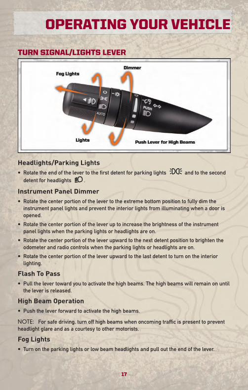
TURN SIGNAL/LIGHTS LEVER
Headlights/Parking Lights• Rotate the end of the lever to the first detent for parking lights and to the second
detent for headlights .
Instrument Panel Dimmer• Rotate the center portion of the lever to the extreme bottom position to fully dim the
instrument panel lights and prevent the interior lights from illuminating when a door isopened.
• Rotate the center portion of the lever up to increase the brightness of the instrumentpanel lights when the parking lights or headlights are on.
• Rotate the center portion of the lever upward to the next detent position to brighten theodometer and radio controls when the parking lights or headlights are on.
• Rotate the center portion of the lever upward to the last detent to turn on the interiorlighting.
Flash To Pass• Pull the lever toward you to activate the high beams. The high beams will remain on until
the lever is released.
High Beam Operation• Push the lever forward to activate the high beams.
NOTE: For safe driving, turn off high beams when oncoming traffic is present to preventheadlight glare and as a courtesy to other motorists.
Fog Lights• Turn on the parking lights or low beam headlights and pull out the end of the lever.
17
OPERATING YOUR VEHICLE
Turn Signals/Lane Change Assist• Tap the lever up or down once and the turn signal (right or left) will flash three times and
automatically turn off.
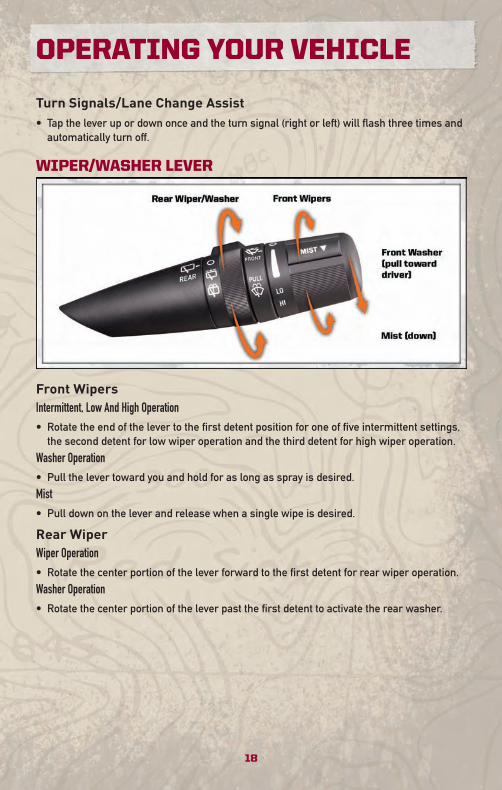
WIPER/WASHER LEVER
Front WipersIntermittent, Low And High Operation• Rotate the end of the lever to the first detent position for one of five intermittent settings,
the second detent for low wiper operation and the third detent for high wiper operation.
Washer Operation• Pull the lever toward you and hold for as long as spray is desired.
Mist• Pull down on the lever and release when a single wipe is desired.
Rear WiperWiper Operation• Rotate the center portion of the lever forward to the first detent for rear wiper operation.
Washer Operation• Rotate the center portion of the lever past the first detent to activate the rear washer.
OPERATING YOUR VEHICLE
18
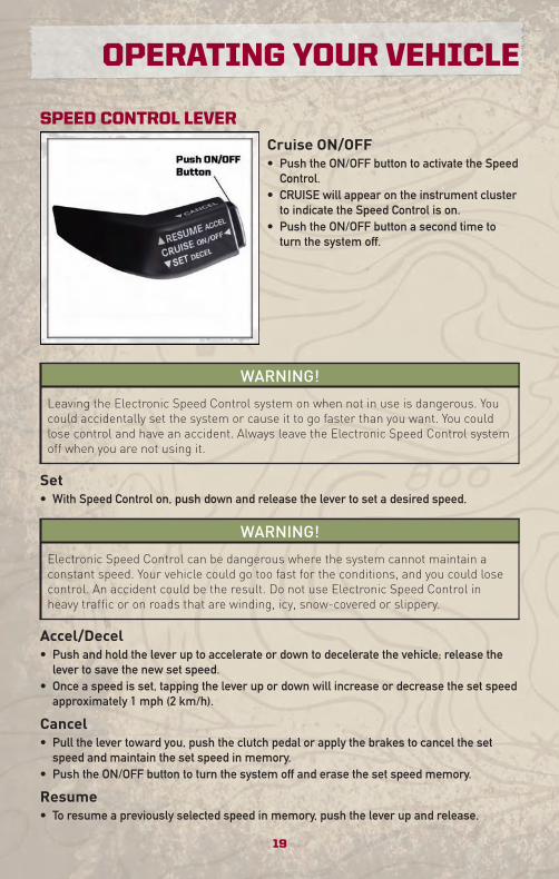
SPEED CONTROL LEVER
Cruise ON/OFF• Push the ON/OFF button to activate the Speed
Control.• CRUISE will appear on the instrument cluster
to indicate the Speed Control is on.• Push the ON/OFF button a second time to
turn the system off.
WARNING!
Leaving the Electronic Speed Control system on when not in use is dangerous. Youcould accidentally set the system or cause it to go faster than you want. You couldlose control and have an accident. Always leave the Electronic Speed Control systemoff when you are not using it.
Set• With Speed Control on, push down and release the lever to set a desired speed.
WARNING!
Electronic Speed Control can be dangerous where the system cannot maintain aconstant speed. Your vehicle could go too fast for the conditions, and you could losecontrol. An accident could be the result. Do not use Electronic Speed Control inheavy traffic or on roads that are winding, icy, snow-covered or slippery.
Accel/Decel• Push and hold the lever up to accelerate or down to decelerate the vehicle; release the
lever to save the new set speed.• Once a speed is set, tapping the lever up or down will increase or decrease the set speed
approximately 1 mph (2 km/h).
Cancel• Pull the lever toward you, push the clutch pedal or apply the brakes to cancel the set
speed and maintain the set speed in memory.• Push the ON/OFF button to turn the system off and erase the set speed memory.
Resume• To resume a previously selected speed in memory, push the lever up and release.
19
OPERATING YOUR VEHICLE
CONTINUOUSLY VARIABLE AUTOMATIC TRANSMISSION(CVT)• While conventional automatic transmissions typically have 4, 5 or 6 speeds, the
Continuously Variable Transmission (CVT) has an infinite number of speeds. This allowsit to adjust to exactly the right ratio to optimize performance and fuel economy.
• Under hard acceleration, you may hear more engine noise than with a conventionaltransmission. The CVT may also occasionally feel like it is “shifting.” Thesecharacteristics are perfectly normal and contribute to the CVT's efficiency.
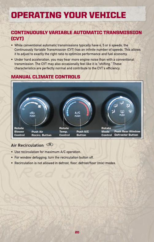
MANUAL CLIMATE CONTROLS
Air Recirculation
• Use recirculation for maximum A/C operation.
• For window defogging, turn the recirculation button off.
• Recirculation is not allowed in defrost, floor, defrost/floor (mix) modes.
OPERATING YOUR VEHICLE
20
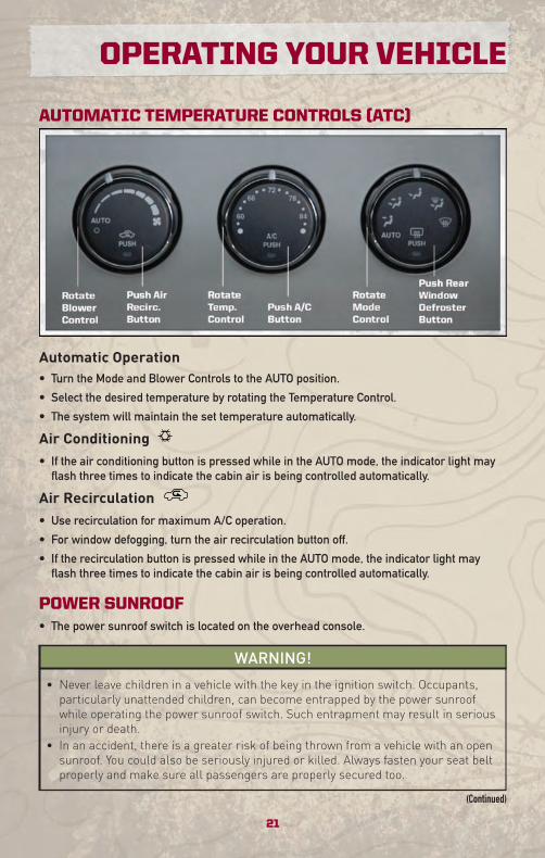
AUTOMATIC TEMPERATURE CONTROLS (ATC)
Automatic Operation• Turn the Mode and Blower Controls to the AUTO position.
• Select the desired temperature by rotating the Temperature Control.
• The system will maintain the set temperature automatically.
Air Conditioning• If the air conditioning button is pressed while in the AUTO mode, the indicator light may
flash three times to indicate the cabin air is being controlled automatically.
Air Recirculation• Use recirculation for maximum A/C operation.
• For window defogging, turn the air recirculation button off.
• If the recirculation button is pressed while in the AUTO mode, the indicator light mayflash three times to indicate the cabin air is being controlled automatically.
POWER SUNROOF• The power sunroof switch is located on the overhead console.
WARNING!
• Never leave children in a vehicle with the key in the ignition switch. Occupants,particularly unattended children, can become entrapped by the power sunroofwhile operating the power sunroof switch. Such entrapment may result in seriousinjury or death.
• In an accident, there is a greater risk of being thrown from a vehicle with an opensunroof. You could also be seriously injured or killed. Always fasten your seat beltproperly and make sure all passengers are properly secured too.
(Continued)
21
OPERATING YOUR VEHICLE
WARNING! (Continued)
• Do not allow small children to operate the sunroof. Never allow your fingers, otherbody parts, or any object to project through the sunroof opening. Injury may result.
Opening SunroofExpress• Press the switch rearward and release. The sunroof will fully open and stop
automatically.
Closing SunroofExpress• Press the switch forward and release. The sunroof will close automatically from any
position.
Manual Open/Close• Press and hold the switch rearward to open or forward to close the sunroof. Any release
of the switch will stop the movement, and the sunroof will remain in a partially open orclosed position until the switch is pressed again.
Venting Sunroof• Press and release the "VENT" button, and the sunroof will open to the vent position. This
is called “Express Vent” and will occur regardless of sunroof position. During ExpressVent operation, any movement of the switch will stop the sunroof.
Pinch Protection Feature• This feature will detect an obstruction in the opening of the sunroof during Express Close
operation. If an obstruction in the path of the sunroof is detected, the sunroof willautomatically return to the open position.
NOTE: Pinch protection is disabled while the switch is pressed and held during manualopening and closing of the sunroof.
WIND BUFFETING• Wind buffeting can be described as a helicopter-type percussion sound. If buffeting
occurs with the rear windows open, adjust the front and rear windows together.
• If buffeting occurs with the sunroof open, adjust the sunroof opening, or adjust anywindow. This will minimize buffeting.
OPERATING YOUR VEHICLE
22
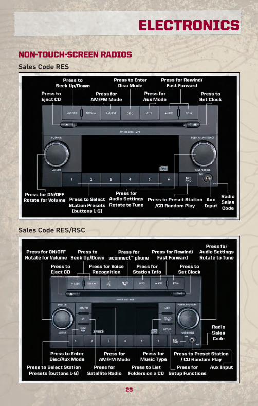
NON-TOUCH-SCREEN RADIOS
Sales Code RES
Sales Code RES/RSC
23
ELECTRONICS
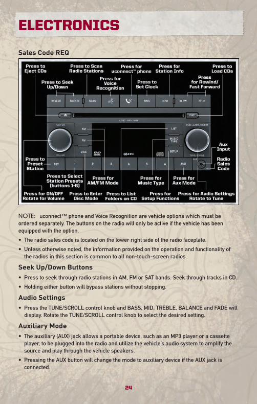
Sales Code REQ
NOTE: uconnect™ phone and Voice Recognition are vehicle options which must beordered separately. The buttons on the radio will only be active if the vehicle has beenequipped with the option.
• The radio sales code is located on the lower right side of the radio faceplate.
• Unless otherwise noted, the information provided on the operation and functionality ofthe radios in this section is common to all non-touch-screen radios.
Seek Up/Down Buttons• Press to seek through radio stations in AM, FM or SAT bands. Seek through tracks in CD.
• Holding either button will bypass stations without stopping.
Audio Settings• Press the TUNE/SCROLL control knob and BASS, MID, TREBLE, BALANCE and FADE will
display. Rotate the TUNE/SCROLL control knob to select the desired setting.
Auxiliary Mode• The auxiliary (AUX) jack allows a portable device, such as an MP3 player or a cassette
player, to be plugged into the radio and utilize the vehicle’s audio system to amplify thesource and play through the vehicle speakers.
• Pressing the AUX button will change the mode to auxiliary device if the AUX jack isconnected.
ELECTRONICS
24
• The control of the external device cannot be provided by the radio; use the device controlsinstead.
Clock Setting• Press and hold the TIME button until the hours blink; turn the TUNE/SCROLL control
knob to set the hours.
• Press the TUNE/SCROLL control knob until the minutes begin to blink; turn theTUNE/SCROLL control knob to set the minutes.
• Press the TUNE/SCROLL control knob to save the time change.
• To exit, press any button/knob or wait five seconds.
Station Presets• Press the SET/RND button once and SET 1 will show in the display. Then select the button
(1–6).
• A second station may be added to each push button. Press the SET/RND button twice andSET 2 will show in the display, then select button (1–6).
How To Load Multiple CDs/DVDs
REQ Radio Only
• Press the LOAD button and then press the button with the corresponding number (1–6)where the CD is being loaded. The radio will display PLEASE WAIT and prompt when toINSERT DISC.
• After the radio displays INSERT DISC, insert the CD into the player. The radio display willshow LOADING DISC when the disc is loading and “READING DISC” when the radio isreading the disc.
• Press the eject button and then the corresponding number (1–6) to eject the desired disc.
25
ELECTRONICS
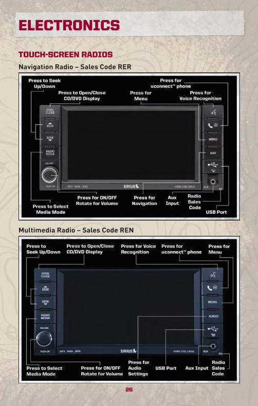
TOUCH-SCREEN RADIOS
Navigation Radio – Sales Code RER
Multimedia Radio – Sales Code REN
ELECTRONICS
26
NOTE: uconnect™ phone and Voice Recognition are vehicle options which must beordered separately. The buttons on the radio will only be active if the vehicle has beenequipped with the option.
• The radio sales code is located on the lower right side of the radio faceplate.
• Unless otherwise noted, the information provided on the operation and functionality ofthe radios in this section is common to all touch-screen radios.
Seek Up/Down• Press to seek through radio stations in AM, FM, or SAT bands. Seek through tracks in CD
or iPod® modes or through songs in the HDD playlist.
Radio Mode• Press the RADIO/MEDIA hard-key to display the different radio modes, then press the
desired soft-key to select AM, FM, SAT, HDD, Disk or AUX modes.
Auxiliary Mode• The auxiliary (AUX) jack allows a portable device, such as an MP3 player or a cassette
player, to be plugged into the radio and utilize the vehicle’s audio system to amplify thesource and play through the vehicle speakers.
• The display will switch automatically to the AUX mode when a 3.5 mm stereo mini-jackcable has been connected.
• To change radio modes while the cable is connected to the unit, press the RADIO/MEDIAhard-key until the AUX tab is displayed on the top of the screen. Touch the AUX tab toreturn to the AUX mode.
• The control of the external device cannot be provided by the radio; use the device controlsinstead.
Clock Setting• Turn the radio on, then touch the screen where the time is displayed.
• Touch the USER CLOCK soft-key (Navigation radio only).
• To adjust the hours, touch either the HOUR FORWARD or HOUR BACKWARD soft-key.
• To adjust the minutes, touch either the MINUTE FORWARD or MINUTE BACKWARDsoft-key.
• To save the new time setting, touch the screen where the word “Save” is displayed.
Store Radio Presets• Press the RADIO/MEDIA hard-key repeatedly until AM FM SAT is displayed in the upper
left corner of the screen.
• Select the radio band by touching either the AM, FM, or SAT soft-key.
• Find the station to store by either pressing the SEEK UP/DOWN hard-key, or touching theSCAN soft-key, DIRECT TUNE soft-key or the left and right arrows.
• Once the station is found, touch and hold one of the PRESET soft-keys in the list to theright, until you hear a confirmation beep.
27
ELECTRONICS
Hard Disc Drive Operation
Copy Complete Audio Disc To Hard-Drive
• Press the OPEN/CLOSE hard-key and insert a disc, then press the MENU hard-key.
• Touch the MY FILES soft-key, then select MY MUSIC.
• Touch the IMPORT MUSIC soft-key, then touch the FROM DISC soft-key in the next screento start the process.
Copying From USB
• Insert a USB device, then select MY MUSIC.
• Touch the IMPORT MUSIC FILES soft-key, then touch the FROM USB soft-key in the nextscreen.
• Select the folders or titles you would like to copy, then touch the DONE soft-key to startthe copy process.
Copy Pictures To The Hard-Drive
• Insert either a CD or a USB device containing your pictures.
• Touch the MY FILES soft-key, then go to the MANAGE MY FILES screen.
• Touch the MY PICTURES soft-key to get an overview of the currently stored images.
• Touch one of the ADD PICTURES soft-keys, then select the type of media inserted.
• Use the PAGE soft-keys to page through a list of pictures and press the picture you wouldlike to import.
• Confirm your selection by touching the YES soft-key. The imported picture is nowavailable in the MANAGE MY PICTURES screen.
• In order to display the imported picture in the radio screen, touch the desired picturesoft-key.
• Select this picture by pressing the PICTURE VIEW soft-key. A check mark indicates thecurrently used picture.
Cleaning Your Touch-Screen Radio• Do not spray any liquid or caustic chemicals directly on the screen. Use a clean and dry
micro fiber lens cleaning cloth in order to clean the touch-screen.
• If necessary, use a lint-free cloth dampened with a cleaning solution such as isopropylalcohol or an isopropyl alcohol and water solution ratio of 50:50. Be sure to follow thesolvent manufacturer's precautions and directions.
Navigation
Navigation Radio – RER Only
• Navigation radios require digital data from a navigation database. The data in thenavigation database is licensed from Navigation Technologies®. Not all roads aredigitized.
ELECTRONICS
28
• For software updates, visit http://www.chrysler.com/en/owners/mygig/ website, visithttp://www.navteq.com website, or contact your authorized dealer for the latest availablesoftware.
NOTE: Many features of this radio are speed dependent. For your own safety, it is notpossible to use the touch-screen keyboard to enter a name (e.g., street name) while thevehicle is in motion. Pull over at a safe location to complete your task.• The Navigation system receives GPS signals from satellites to display the position of your
vehicle.
New Destination• Press the NAV hard-key to access the Navigation Main Menu.• Touch the NEW DESTINATION soft-key to program a destination, then select the
destination soft-key of your choice.
Program/Storing Home Address• Press the NAV hard-key to access the Navigation Main Menu.• Touch the GUIDE ME HOME soft-key, then touch the STREET ADDRESS soft-key.• Touch the STATE soft-key, then enter your state name into the speller; select your state
from the list and press the CHANGE soft-key.• Touch the INPUT STREET NAME soft-key and enter your street name into the speller.• Touch the CONTINUE soft-key and enter your address into the speller; then touch the
CONTINUE soft-key again.• Touch the city name and touch the SAVE soft-key to complete programming.
Change Stored Home Address• Press the MENU hard-key, then touch the MY FILES soft-key.• Touch the MY ADDRESS BOOK soft-key, then touch the HOME soft-key.• In the Home Address Information screen, touch the EDIT CONTACT soft-key, then touch
the CHANGE ADDRESS soft-key in the next screen.• Touch the INPUT STREET NAME soft-key and enter your street name into the speller.• Touch the CONTINUE soft-key and enter your address into the speller; touch the
CONTINUE soft-key again.• Touch the city name and touch the SAVE soft-key to complete programming.
Guide Me Home• Press the NAV hard-key to access the Navigation Main Menu.• Touch the GUIDE ME HOME soft-key to route you back to your home destination from
your current location. Touch the GO soft-key to start your trip.
Map• Press the NAV hard-key to access the Navigation Main Menu.• Touch the MAP soft-key to display a map of your current position.
29
ELECTRONICS
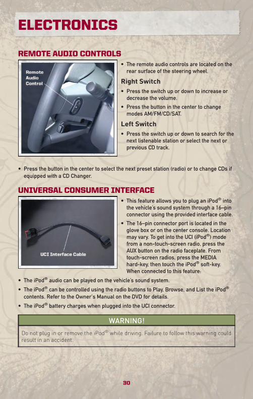
REMOTE AUDIO CONTROLS• The remote audio controls are located on the
rear surface of the steering wheel.
Right Switch• Press the switch up or down to increase or
decrease the volume.
• Press the button in the center to changemodes AM/FM/CD/SAT.
Left Switch• Press the switch up or down to search for the
next listenable station or select the next orprevious CD track.
• Press the button in the center to select the next preset station (radio) or to change CDs ifequipped with a CD Changer.
UNIVERSAL CONSUMER INTERFACE• This feature allows you to plug an iPod® into
the vehicle’s sound system through a 16–pinconnector using the provided interface cable.
• The 16–pin connector port is located in theglove box or on the center console. Locationmay vary. To get into the UCI (iPod®) modefrom a non-touch-screen radio, press theAUX button on the radio faceplate. Fromtouch-screen radios, press the MEDIAhard-key, then touch the iPod® soft-key.When connected to this feature:
• The iPod® audio can be played on the vehicle’s sound system.
• The iPod® can be controlled using the radio buttons to Play, Browse, and List the iPod®
contents. Refer to the Owner's Manual on the DVD for details.
• The iPod® battery charges when plugged into the UCI connector.
WARNING!
Do not plug in or remove the iPod® while driving. Failure to follow this warning couldresult in an accident.
ELECTRONICS
30
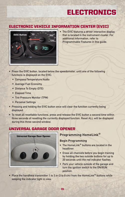
ELECTRONIC VEHICLE INFORMATION CENTER (EVIC)• The EVIC features a driver interactive display
that is located in the instrument cluster. Foradditional information, refer toProgrammable Features in this guide.
• Press the EVIC button, located below the speedometer, until one of the followingfunctions is displayed on the EVIC:
• Compass/Temperature/Audio
• Average Fuel Economy
• Distance To Empty (DTE)
• Elapsed Time
• Tire Pressure Monitor (TPM)
• Personal Settings
• Pressing and holding the EVIC button once will clear the function currently beingdisplayed.
• To reset all resettable functions, press and release the EVIC button a second time withinthree seconds of resetting the currently displayed function. Reset ALL will be displayedduring this three-second window.
UNIVERSAL GARAGE DOOR OPENER
Programming HomeLink®
Begin Programming• The HomeLink® buttons are located in the
headliner.
• Erase all channels before you begin trainingby holding the two outside buttons for up to20 seconds until the red indicator flashes.
• Park your vehicle outside of the garage andturn the ignition switch to the ON/RUNposition.
• Place the handheld transmitter 1 to 3 in (3 to 8 cm) from the HomeLink® buttons whilekeeping the indicator light in view.
31
ELECTRONICS
• Simultaneously, press and hold both the chosen HomeLink® button and the handheldtransmitter button until the HomeLink® indicator flash rate changes from a slow to arapidly blinking light, then release both the HomeLink® and the handheld transmitterbuttons. This may take up to 30 seconds, or longer in rare cases.
• Press and hold the just-trained HomeLink® button; if the indicator light stays onconstantly, programming is complete and the garage door should open.
WARNING!
• Your motorized door or gate will open and close while you are training theuniversal transceiver. Do not train the transceiver if people or pets are in the pathof the door or gate. Only use this transceiver with a garage door opener that has a“stop and reverse” feature as required by Federal safety standards. This includesmost garage door opener models manufactured after 1982. Do not use a garagedoor opener without these safety features. Call toll-free 1–800–355–3515 or, onthe Internet, at www.HomeLink.com for safety information or assistance.
• Vehicle exhaust contains Carbon Monoxide (CO), a dangerous gas. Do not run yourvehicle in the garage while training the transceiver. Exhaust gas can cause seriousinjury or death.
NOTE: If you are having difficulty training your HomeLink® and your garage door openerwas manufactured after 1995, you may have a rolling code. Follow the steps below forProgramming A Rolling Code System.
Programming A Rolling Code System
• At the garage door opener motor (in the garage), locate the “learn” or “training” button.This can usually be found where the hanging antenna wire is attached to the garage dooropener motor (it is not the button normally used to open and close the door).
• Firmly press and release the “learn” or “training” button then, within 30 seconds, returnto the vehicle and press the programmed HomeLink® button twice (holding the button fortwo seconds each time). If the device is plugged in and activates, programming iscomplete.
• If the device does not activate, press the button a third time (for two seconds) to completethe training.
Using HomeLink®
• To operate, simply press and release the programmed HomeLink® button and thetrained device will operate.
• Refer to your Owner’s Manual on the DVD for further details. If you have any problemsprogramming HomeLink®, or require assistance, please call toll-free 1–800–355–3515 or,on the Internet, at www.HomeLink.com.
ELECTRONICS
32
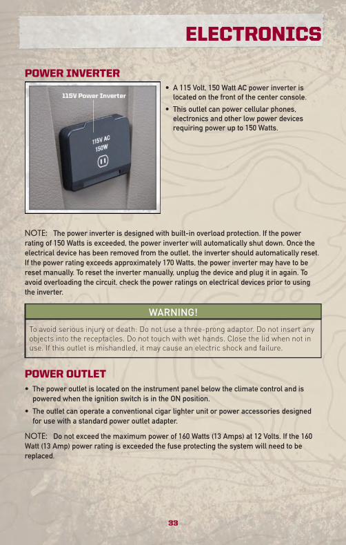
POWER INVERTER• A 115 Volt, 150 Watt AC power inverter is
located on the front of the center console.
• This outlet can power cellular phones,electronics and other low power devicesrequiring power up to 150 Watts.
NOTE: The power inverter is designed with built-in overload protection. If the powerrating of 150 Watts is exceeded, the power inverter will automatically shut down. Once theelectrical device has been removed from the outlet, the inverter should automatically reset.If the power rating exceeds approximately 170 Watts, the power inverter may have to bereset manually. To reset the inverter manually, unplug the device and plug it in again. Toavoid overloading the circuit, check the power ratings on electrical devices prior to usingthe inverter.
WARNING!
To avoid serious injury or death: Do not use a three-prong adaptor. Do not insert anyobjects into the receptacles. Do not touch with wet hands. Close the lid when not inuse. If this outlet is mishandled, it may cause an electric shock and failure.
POWER OUTLET• The power outlet is located on the instrument panel below the climate control and is
powered when the ignition switch is in the ON position.
• The outlet can operate a conventional cigar lighter unit or power accessories designedfor use with a standard power outlet adapter.
NOTE: Do not exceed the maximum power of 160 Watts (13 Amps) at 12 Volts. If the 160Watt (13 Amp) power rating is exceeded the fuse protecting the system will need to bereplaced.
33
ELECTRONICS
uconnect™ phone• The uconnect™ phone is a voice-activated, hands-free, in-vehicle communications
system.
• The uconnect™ phone allows you to dial a phone number with your cellular phone usingsimple voice commands.
• Please refer to uconnect™ phone in the uconnect™ User's Manual on the DVD forfurther details.
WARNING!
• Any voice commanded system should be used only in safe driving conditionsfollowing local laws and phone use. All attention should be kept on the roadwayahead. Failure to do so may result in an accident causing serious injury or death.
• Your phone must be turned on and paired to the uconnect™ phone to allow use ofthis vehicle feature in emergency situations, when the cellular phone has networkcoverage and stays paired to the uconnect™ phone.
NOTE: The uconnect™ phone requires a cellular phone equipped with the Bluetooth®
Hands-Free Profile, Version 0.96 or higher. For uconnect™ customer support, call1–877–855–8400.
Phone Pairing
NOTE: Pairing is a one-time initial setup before using the phone. You will also need tofollow the Bluetooth® instructions in your cell phone user guide to complete the phonepairing setup.
• Press the Phone button to begin.
• Wait for the “ready” prompt and beep.
• (After the BEEP), say “uconnect setup”.
• (After the BEEP), say “phone pairing”.
• (After the BEEP), say “pair a phone”.
• Follow the audible prompts.
• You will be asked to create a four-digit PIN which you will later need to enter into yourphone (typically...settings, bluetooth®, device, list, new).
• You will then be prompted to give the phone pairing a name (each phone paired shouldhave a unique name).
• Next you will be asked to give this new pairing a priority of 1 thru 7 (up to seven phonesmay be paired).
Making A Phone Call• Press the Phone button .
• (After the BEEP), say “dial” (or “call” to a name).
• (After the BEEP), say number (or name).
ELECTRONICS
34
Phonebook (uconnect™ local) Edit• Press the Phone button .
• (After the BEEP), say “phonebook”.
• (After the BEEP), say “new entry” or “list names” or “delete”.
• Follow the prompts.
Receiving A Call – Accept (And End)• When an incoming call rings/is announced on uconnect™, press the Phone button .
• To end a call, press the Phone button .
Mute (Or Unmute) Microphone During Call• During a call, press the Voice button .
• (After the BEEP), say “mute on” (or “mute off”).
Transfer Ongoing Call Between Handset And Vehicle• During a call, press the Voice button .
• (After the BEEP), say “transfer call”.
Changing The Volume• Start a dialogue by pressing the Phone button , then adjust the volume during a
normal call.
• Use the radio ON/OFF VOLUME rotary knob to adjust the volume to a comfortable levelwhile the uconnect™ system is speaking. Please note the volume setting for uconnect™is different than the audio system.
NOTE: To access the tutorial, press the uconnect™ hard-key. After the BEEP, say“tutorial”. Press any hard-key or touch the display to cancel the tutorial.
35
ELECTRONICS
VOICE RECOGNITION• The Voice Recognition (VR) system allows you to control your AM, FM radio, satellite
radio, disc player, and a memo recorder. When you press the VR button , you willhear a beep. The beep is your signal to give a command. If you do not say a commandwithin a few seconds, the system will present you with a list of options. If you ever wishto interrupt the system while it lists options, press the VR button , listen for the BEEP,and say your command.
• Please refer to uconnect™ tunes in the uconnect™ User's Manual on the DVD for furtherdetails.
Changing The Volume• Start a dialogue by pressing the VR button , then say a command (e.g., “tutorial”).
• Use the radio ON/OFF VOLUME rotary knob to adjust the volume to a comfortable levelwhile the Voice Recognition system is speaking. Please note the volume setting for VoiceRecognition is different than the audio system.
WARNING!
Any voice commanded system should be used only in safe driving conditions and allattention should be kept on the roadway ahead. Failure to do so may result in anaccident causing serious injury or death.
NOTE: To access the tutorial, press the VR button . After the BEEP, say “tutorial”.Press any hard-key or touch the display to cancel the tutorial.
ELECTRONICS
36
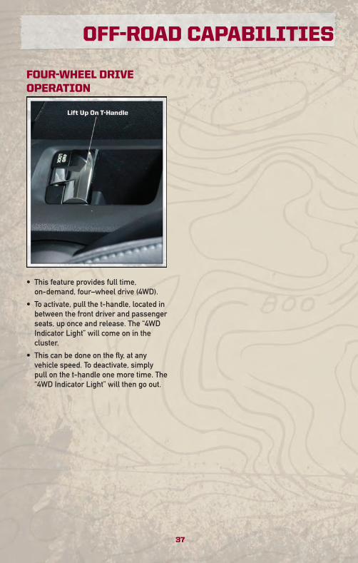
FOUR-WHEEL DRIVEOPERATION
• This feature provides full time,on-demand, four–wheel drive (4WD).
• To activate, pull the t-handle, located inbetween the front driver and passengerseats, up once and release. The “4WDIndicator Light” will come on in thecluster.
• This can be done on the fly, at anyvehicle speed. To deactivate, simplypull on the t-handle one more time. The“4WD Indicator Light” will then go out.
37
OFF-ROAD CAPABILITIES
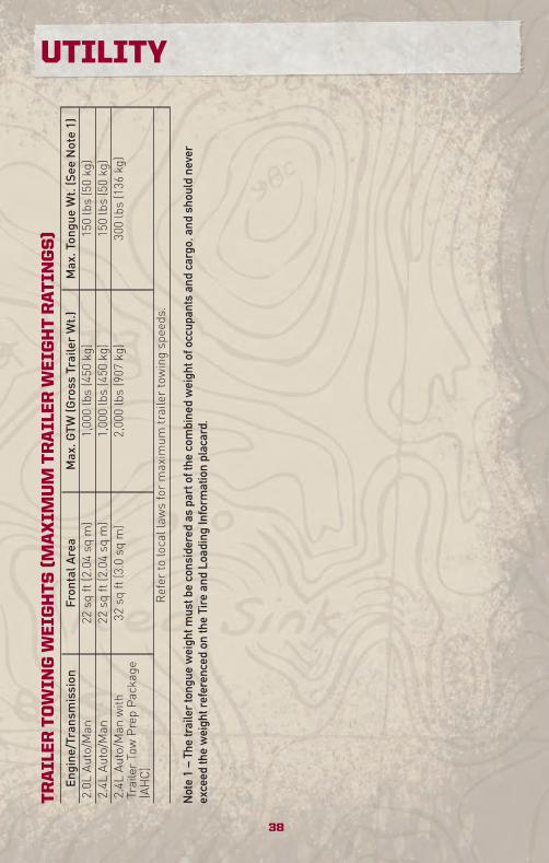
TR
AIL
ER
TO
WIN
GW
EIG
HT
S(M
AX
IMU
MT
RA
ILE
RW
EIG
HT
RA
TIN
GS
)En
gine/Transmission
FrontalA
rea
Max.G
TW(Gross
TrailerWt.)
Max.TongueWt.(See
Note1)
2.0L
Auto/M
an22
sqft(2.04sq
m)
1,000lbs(450
kg)
150lbs(50kg)
2.4L
Auto/M
an22
sqft(2.04sq
m)
1,000lbs(450
kg)
150lbs(50kg)
2.4L
Auto/M
anwith
TrailerTowPrepPackage
(AHC)
32sq
ft(3.0sq
m)
2,000lbs(907
kg)
300lbs(136
kg)
Refer
tolocallaw
sformaximum
trailertowingspeeds.
Not
e1
–Th
etr
aile
rto
ngue
wei
ghtm
ustb
eco
nsid
ered
aspa
rtof
the
com
bine
dw
eigh
tofo
ccup
ants
and
carg
o,an
dsh
ould
neve
rex
ceed
the
wei
ghtr
efer
ence
don
the
Tire
and
Load
ing
Info
rmat
ion
plac
ard.
38
UTILITY
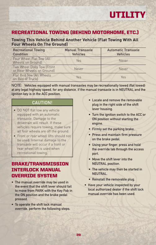
RECREATIONAL TOWING (BEHIND MOTORHOME, ETC.)
Towing This Vehicle Behind Another Vehicle (Flat Towing With AllFour Wheels On The Ground)Recreational TowingCondition
Manual TransaxleVehicles
Automatic TransaxleVehicles
Four Wheel Flat Tow (AllWheels on Ground) Yes Never
Two Wheel Dolly Tow (Frontor Rear Wheels on Ground) Never Never
Flat Bed Tow (All Wheelson Bed of Truck) Yes Yes
NOTE: Vehicles equipped with manual transaxles may be recreationally towed (flat towed)at any legal highway speed, for any distance, if the manual transaxle is in NEUTRAL and theignition key is in the ACC position.
CAUTION!
• DO NOT flat tow any vehicleequipped with an automatictransaxle. Damage to thedrivetrain will result. If thesevehicles require towing, make sureall four wheels are off the ground.
• Front or rear wheel lifts should notbe used. Internal damage to thetransaxle will occur if a front orrear wheel lift is used whenrecreational towing.
BRAKE/TRANSMISSIONINTERLOCK MANUALOVERRIDE SYSTEM• The manual override may be used in
the event that the shift lever should failto move from PARK with the Key Fob inthe ON position and the brake pedalpressed.
• To operate the shift lock manualoverride, perform the following steps:
• Locate and remove the removableplug in the right side of the shiftlever housing.
• Turn the ignition switch to the ACC orON position without starting theengine.
• Firmly set the parking brake.
• Press and maintain firm pressureon the brake pedal.
• Using your finger, press and holdthe override tab through the accessport.
• Move the shift lever into theNEUTRAL position.
• The vehicle may then be started inNEUTRAL.
• Reinstall the removable plug.
• Have your vehicle inspected by yourlocal authorized dealer if the shift lockmanual override has been used.
39
UTILITY
24 HOUR TOWING ASSISTANCE - U.S. ONLY• Dial toll-free 1-800-521-2779.
• Provide your name, vehicle identification number and license plate number.
• Provide your location, including telephone number, from which you are calling.
• Briefly describe the nature of the problem and answer a few simple questions.
• You will be given the name of the service provider and an estimated time of arrival. If youfeel you are in an “unsafe situation”, please let us know. With your consent, we willcontact local police or safety authorities.
INSTRUMENT CLUSTER WARNING LIGHTS
- Electronic Stability Control (ESC) Malfunction Indicator Light
• If the “ESC Malfunction Indicator Light” comes on continuously with the engine running, amalfunction has been detected in the ESC system. If this light remains on after severalignition cycles, and the vehicle has been driven several miles (kilometers) at speedsgreater than 30 mph (48 km/h), we recommend you drive to the nearest service center assoon as possible to have the problem diagnosed and corrected.
• The “ESC Malfunction Indicator Light” starts to flash as soon as the tires lose traction andthe ESC system becomes active. If the light begins to flash during acceleration, ease upon the accelerator and apply as little throttle as possible. Be sure to adapt your speedand driving to the prevailing road conditions. The light also flashes when TCS is active. Toimprove the vehicle's traction when starting off in deep snow, sand or gravel, it may bedesirable to switch the ESC system to Partial Off mode by momentarily pressing the ESCOff switch.
- Tire Pressure Monitoring System (TPMS) Light• A Tire Pressure Monitoring Light and a “low tire” message will display in your instrument
cluster along with an audible chime if one or more of your vehicle’s four road tires aresignificantly under-inflated.
• Check the inflation pressure of each tire and inflate to the recommended pressure foryour vehicle. The tire pressures recommended for your vehicle are found on the “Tire andLoading Information” label located on the driver’s side door opening. The TPMS lightshould not be used as a tire pressure gauge when adjusting your tire pressure.
• It is recommended that you check the tire pressure in the morning when tires are cool;inflate each tire to the recommended pressure for your vehicle. The light will turn offafter your vehicle’s tire pressures are properly inflated and the pressure has beenrecognized. The vehicle may need to be driven for up to 20 minutes above 15 mph(25 km/h) before the light will turn off.
• Temperature changes can affect tire pressure, causing the TPMS light to turn on. Tirepressures will also increase as the vehicle is driven – this is normal and you should notadjust for this increased pressure.
• Driving on under-inflated tires reduces your vehicle’s fuel efficiency and tire tread life. If aspare tire is in use on the vehicle, the TPMS light may turn on.
WHAT TO DO IN EMERGENCIES
40
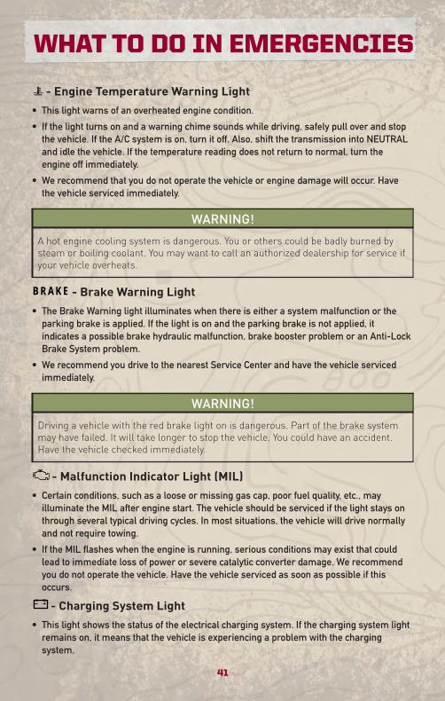
- Engine Temperature Warning Light
• This light warns of an overheated engine condition.
• If the light turns on and a warning chime sounds while driving, safely pull over and stopthe vehicle. If the A/C system is on, turn it off. Also, shift the transmission into NEUTRALand idle the vehicle. If the temperature reading does not return to normal, turn theengine off immediately.
• We recommend that you do not operate the vehicle or engine damage will occur. Havethe vehicle serviced immediately.
WARNING!
A hot engine cooling system is dangerous. You or others could be badly burned bysteam or boiling coolant. You may want to call an authorized dealership for service ifyour vehicle overheats.
BRAKE - Brake Warning Light
• The Brake Warning light illuminates when there is either a system malfunction or theparking brake is applied. If the light is on and the parking brake is not applied, itindicates a possible brake hydraulic malfunction, brake booster problem or an Anti-LockBrake System problem.
• We recommend you drive to the nearest Service Center and have the vehicle servicedimmediately.
WARNING!
Driving a vehicle with the red brake light on is dangerous. Part of the brake systemmay have failed. It will take longer to stop the vehicle. You could have an accident.Have the vehicle checked immediately.
- Malfunction Indicator Light (MIL)
• Certain conditions, such as a loose or missing gas cap, poor fuel quality, etc., mayilluminate the MIL after engine start. The vehicle should be serviced if the light stays onthrough several typical driving cycles. In most situations, the vehicle will drive normallyand not require towing.
• If the MIL flashes when the engine is running, serious conditions may exist that couldlead to immediate loss of power or severe catalytic converter damage. We recommendyou do not operate the vehicle. Have the vehicle serviced as soon as possible if thisoccurs.
- Charging System Light
• This light shows the status of the electrical charging system. If the charging system lightremains on, it means that the vehicle is experiencing a problem with the chargingsystem.
41
WHAT TO DO IN EMERGENCIES
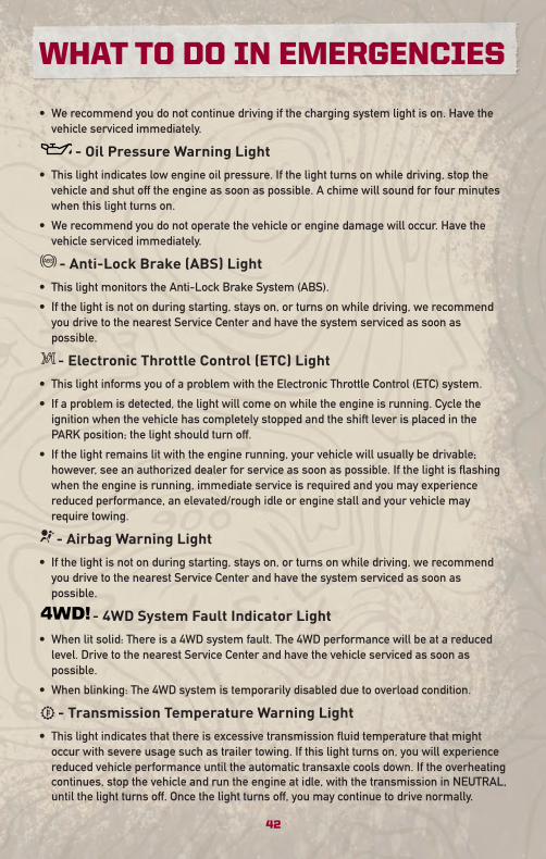
• We recommend you do not continue driving if the charging system light is on. Have thevehicle serviced immediately.
- Oil Pressure Warning Light
• This light indicates low engine oil pressure. If the light turns on while driving, stop thevehicle and shut off the engine as soon as possible. A chime will sound for four minuteswhen this light turns on.
• We recommend you do not operate the vehicle or engine damage will occur. Have thevehicle serviced immediately.
- Anti-Lock Brake (ABS) Light
• This light monitors the Anti-Lock Brake System (ABS).
• If the light is not on during starting, stays on, or turns on while driving, we recommendyou drive to the nearest Service Center and have the system serviced as soon aspossible.
- Electronic Throttle Control (ETC) Light
• This light informs you of a problem with the Electronic Throttle Control (ETC) system.
• If a problem is detected, the light will come on while the engine is running. Cycle theignition when the vehicle has completely stopped and the shift lever is placed in thePARK position; the light should turn off.
• If the light remains lit with the engine running, your vehicle will usually be drivable;however, see an authorized dealer for service as soon as possible. If the light is flashingwhen the engine is running, immediate service is required and you may experiencereduced performance, an elevated/rough idle or engine stall and your vehicle mayrequire towing.
- Airbag Warning Light
• If the light is not on during starting, stays on, or turns on while driving, we recommendyou drive to the nearest Service Center and have the system serviced as soon aspossible.
- 4WD System Fault Indicator Light
• When lit solid: There is a 4WD system fault. The 4WD performance will be at a reducedlevel. Drive to the nearest Service Center and have the vehicle serviced as soon aspossible.
• When blinking: The 4WD system is temporarily disabled due to overload condition.
- Transmission Temperature Warning Light
• This light indicates that there is excessive transmission fluid temperature that mightoccur with severe usage such as trailer towing. If this light turns on, you will experiencereduced vehicle performance until the automatic transaxle cools down. If the overheatingcontinues, stop the vehicle and run the engine at idle, with the transmission in NEUTRAL,until the light turns off. Once the light turns off, you may continue to drive normally.
WHAT TO DO IN EMERGENCIES
42
Fuel Cap/Loose Gas Cap Message• If a “gas cap” message (shown as gASCAP) appears, tighten the gas cap until a “clicking”
sound is heard.
• Press the odometer reset button, located below the tachometer, to turn the message off.
• If the message continues to appear for more than three days after tightening the gas cap,see your authorized dealer.
Oil Change IndicatorMessage• If an “oil change” message (shown as CHAngE OIL) appears and a single chime sounds,
it is time for your next required oil change.
Resetting The Light After Servicing• Turn the ignition switch to the ON/RUN position (do not start engine).
• Fully depress the accelerator pedal three times within 10 seconds.
• Turn the ignition switch to the OFF/LOCK position.
IF YOUR ENGINE OVERHEATS• In any of the following situations, you can reduce the potential for overheating by taking
the appropriate action.
• On the highways — slow down.
• In city traffic — while stopped, shift transmission into NEUTRAL, but do not increaseengine idle speed.
NOTE: There are steps that you can take to slow down an impending overheat condition:• If your air conditioner (A/C) is on, turn it off. The A/C system adds heat to the engine
cooling system and turning the A/C off can help remove this heat.• You can also turn the Temperature Control to maximum heat, the Mode Control to floor
and the Fan Control to high. This allows the heater core to act as a supplement to theradiator and aids in removing heat from the engine cooling system.
• If the temperature reading does not return to normal, turn the engine off immediately.• We recommend that you do not operate the vehicle or engine damage will occur. Have
the vehicle serviced immediately.
CAUTION!
Driving with a hot cooling system could damage your vehicle. If the temperaturegauge reads HOT (H), pull over and stop the vehicle. Idle the vehicle with the airconditioner turned off until the pointer drops back into the normal range. If thepointer remains on HOT (H), and you hear continuous chimes, turn the engine offimmediately and call for service.
43
WHAT TO DO IN EMERGENCIES
WARNING!
You or others can be badly burned by hot engine coolant (antifreeze) or steam fromyour radiator. If you see or hear steam coming from under the hood, do not open thehood until the radiator has had time to cool. Never try to open a cooling systempressure cap when the radiator or coolant bottle is hot.
AUTOMATIC TRANSAXLE OVERHEATING• During sustained high speed driving or trailer towing up long grades on hot days, the
automatic transaxle oil may become too hot.
• When the transmission overheat warning light turns on, you will experience reducedperformance until the automatic transaxle cools down. Once the transaxle has cooleddown and the light turns off, you may continue to drive normally. If the high speed ismaintained, the overheating will continue to occur.
• If the overheating continues, it may become necessary to stop the vehicle and run theengine at idle with the transaxle in NEUTRAL until the light turns off.
JACKING AND TIRE CHANGING
WARNING!
• Do not attempt to change a tire on the side of the vehicle close to moving traffic.Pull far enough off the road to avoid the danger of being hit when operating thejack or changing the wheel.
• Getting under a jacked-up vehicle is dangerous. The vehicle could slip off the jackand fall on you. You could be crushed. Never get any part of your body under avehicle that is on a jack. If you need to get under a raised vehicle, take it to aservice center where it can be raised on a lift.
• The jack is designed to use as a tool for changing tires only. The jack should notbe used to lift the vehicle for service purposes. The vehicle should be jacked on afirm, level surface only. Avoid ice or slippery areas.
WARNING!
• The compact spare tire is for emergency use only. Installation of this compactspare tire affects vehicle handling.
• Do not drive more than 50 mph (80 km/h) with a compact spare tire.• Keep the compact spare tire inflated to the cold tire inflation pressure, listed oneither your tire placard or limited use spare tire and wheel assembly.
• Replace (or repair) the original tire at the first opportunity and reinstall it on yourvehicle. Failure to do so could result in loss of vehicle control.
(Continued)
WHAT TO DO IN EMERGENCIES
44
WARNING! (Continued)
• A loose tire or jack, thrown forward in a collision or hard stop, could endanger theoccupants of the vehicle. Always stow the jack parts and spare tire in the placesprovided.
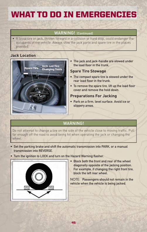
Jack Location• The jack and jack-handle are stowed under
the load floor in the trunk.
Spare Tire Stowage• The compact spare tire is stowed under the
rear load floor in the trunk.
• To remove the spare tire, lift up the load floorcover and remove the hold down.
Preparations For Jacking• Park on a firm, level surface. Avoid ice or
slippery areas.
WARNING!
Do not attempt to change a tire on the side of the vehicle close to moving traffic. Pullfar enough off the road to avoid being hit when operating the jack or changing thewheel.
• Set the parking brake and shift the automatic transmission into PARK, or a manualtransmission into REVERSE.
• Turn the ignition to LOCK and turn on the Hazard Warning flasher.
• Block both the front and rear of the wheeldiagonally opposite of the jacking position.For example, if changing the right front tire,block the left rear wheel.
NOTE: Passengers should not remain in thevehicle when the vehicle is being jacked.
45
WHAT TO DO IN EMERGENCIES
Jacking And Tire Changing Instructions
WARNING!
Carefully follow these tire changing procedures to help prevent personal injury ordamage to your vehicle: Always park on a firm, level surface as far from the edge ofthe roadway as possible before raising the vehicle.
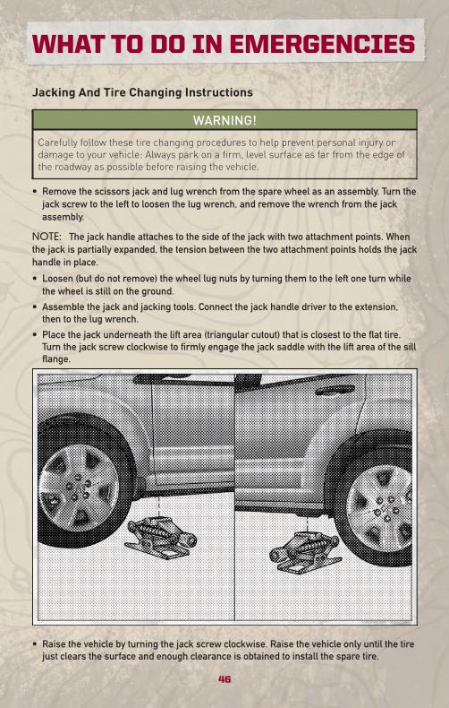
• Remove the scissors jack and lug wrench from the spare wheel as an assembly. Turn thejack screw to the left to loosen the lug wrench, and remove the wrench from the jackassembly.
NOTE: The jack handle attaches to the side of the jack with two attachment points. Whenthe jack is partially expanded, the tension between the two attachment points holds the jackhandle in place.
• Loosen (but do not remove) the wheel lug nuts by turning them to the left one turn whilethe wheel is still on the ground.
• Assemble the jack and jacking tools. Connect the jack handle driver to the extension,then to the lug wrench.
• Place the jack underneath the lift area (triangular cutout) that is closest to the flat tire.Turn the jack screw clockwise to firmly engage the jack saddle with the lift area of the sillflange.
• Raise the vehicle by turning the jack screw clockwise. Raise the vehicle only until the tirejust clears the surface and enough clearance is obtained to install the spare tire.
WHAT TO DO IN EMERGENCIES
46
WARNING!
Raising the vehicle higher than necessary can make the vehicle less stable andcause an accident. It could slip off the jack and hurt someone near it. Raise thevehicle only enough to remove the tire.
• Remove the lug nuts, wheel cover (if equipped) and wheel.
• Position the spare wheel/tire on the vehicle and install the lug nuts with the cone-shapedend toward the wheel. Do NOT attempt to install a center cap or wheel cover on thecompact spare. Lightly tighten the lug nuts clockwise. To avoid the risk of forcing thevehicle off the jack, do not tighten the nuts fully until the vehicle has been lowered.
• Lower the vehicle by turning the jack screw to the left, and remove the jack and wheelblocks.
• Finish tightening the lug nuts. Push down on the wrench while tightening for increasedleverage. Alternate nuts until each one has been tightened twice. The correct wheel nuttightness is 100 ft lbs (135 N•m). If in doubt about the correct tightness, have themchecked with a torque wrench by your authorized dealer or at a service station.
WARNING!
A loose tire or jack, thrown forward in a collision or hard stop, could endanger theoccupants of the vehicle. Always stow the jack parts and the spare tire in the placesprovided.
• Secure the tire, jack, and tools in their proper locations.
JUMP-STARTING
WARNING!
Any procedure other than the following could result in:• Personal injury caused by electrolyte squirting out the battery vent,• Personal injury or property damage due to battery explosion,• Damage to the charging system of the booster vehicle or of the immobilizedvehicle.
WARNING!
• Take care to avoid the radiator cooling fan whenever the hood is raised. It can startanytime the ignition switch is ON. You can be hurt by the fan.
(Continued)
47
WHAT TO DO IN EMERGENCIES
WARNING! (Continued)
• Battery fluid is a corrosive acid solution; do not allow battery fluid to contact eyes,skin or clothing. Do not lean over a battery when attaching clamps or allow theclamps to touch each other. If acid splashes in your eyes or on skin, flush thecontaminated area immediately with large quantities of water.
• A battery generates hydrogen gas which is flammable and explosive. Keep flamesor sparks away from the battery vent holes. Don’t lean over the battery whenattaching clamps or allow the clamps to touch each other.
• If the vehicle has a discharged battery, booster cables may be used to obtain astart from another vehicle. This type of start can be dangerous if done improperly,so follow this procedure carefully.
• Do not use a booster battery or any other booster source with an output thatexceeds 12-volts (i.e., do not use a 24-volt power source).
NOTE: Disconnecting the battery with the ignition in the ON position will cause vehicleswith an automatic transaxle (CVT2) to go into “default mode” and turn on the MalfunctionIndicator Light (MIL). See your authorized dealer to correct this condition.
• Remove all metal jewelry, such as watch bands or bracelets, which might make anunintended electrical contact.
WARNING!
Do not permit vehicles to touch each other as this could establish a groundconnection and personal injury could result.
• Park the booster vehicle within cable reach but without letting the vehicles touch. Set theparking brake on both vehicles, shift the automatic transmission into PARK, or themanual transmission into NEUTRAL, and turn the ignition to LOCK.
• Turn off the heater, radio, and all unnecessary electrical loads.
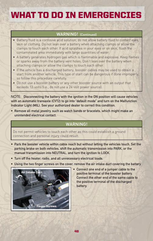
• Using the two finger screws on the cover, remove the air intake duct covering the battery.
• Connect one end of a jumper cable to thepositive terminal of the booster battery.Connect the other end of the same cable tothe positive terminal of the dischargedbattery.
WHAT TO DO IN EMERGENCIES
48
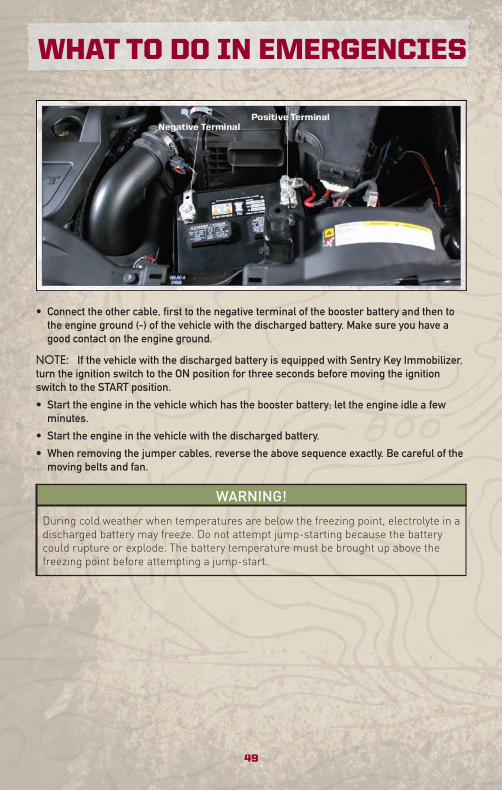
• Connect the other cable, first to the negative terminal of the booster battery and then tothe engine ground (-) of the vehicle with the discharged battery. Make sure you have agood contact on the engine ground.
NOTE: If the vehicle with the discharged battery is equipped with Sentry Key Immobilizer,turn the ignition switch to the ON position for three seconds before moving the ignitionswitch to the START position.
• Start the engine in the vehicle which has the booster battery; let the engine idle a fewminutes.
• Start the engine in the vehicle with the discharged battery.
• When removing the jumper cables, reverse the above sequence exactly. Be careful of themoving belts and fan.
WARNING!
During cold weather when temperatures are below the freezing point, electrolyte in adischarged battery may freeze. Do not attempt jump-starting because the batterycould rupture or explode. The battery temperature must be brought up above thefreezing point before attempting a jump-start.
49
WHAT TO DO IN EMERGENCIES
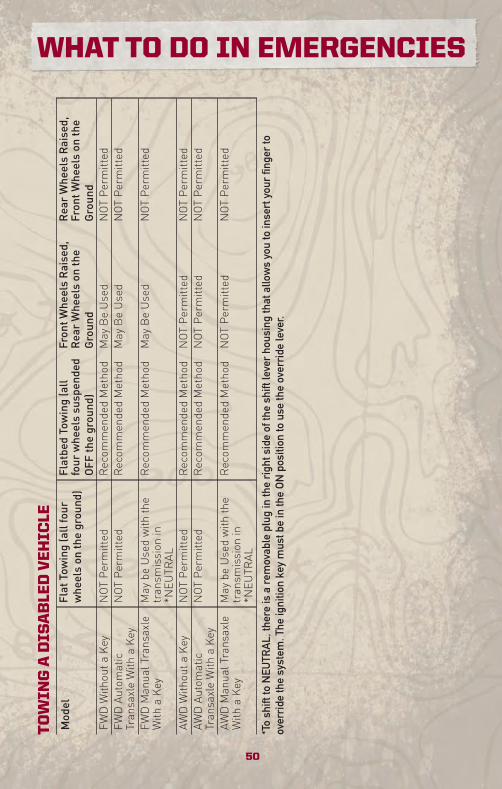
TO
WIN
GA
DIS
AB
LED
VE
HIC
LEModel
FlatTowing(allfour
wheelson
theground)
FlatbedTowing(all
four
wheelssuspended
OFF
theground)
FrontW
heelsRaised,
RearWheelson
the
Ground
RearWheelsRaised,
FrontW
heelson
the
Ground
FWDWithouta
Key
NOTPermitted
Recom
mendedMethod
May
BeUsed
NOTPermitted
FWDAu
tomatic
TransaxleWith
aKey
NOTPermitted
Recom
mendedMethod
May
BeUsed
NOTPermitted
FWDManualTransaxle
With
aKey
May
beUsedwith
the
transm
ission
in*N
EUTR
AL
Recom
mendedMethod
May
BeUsed
NOTPermitted
AWDWithouta
Key
NOTPermitted
Recom
mendedMethod
NOTPermitted
NOTPermitted
AWDAu
tomatic
TransaxleWith
aKey
NOTPermitted
Recom
mendedMethod
NOTPermitted
NOTPermitted
AWDManualTransaxle
With
aKey
May
beUsedwith
the
transm
ission
in*N
EUTR
AL
Recom
mendedMethod
NOTPermitted
NOTPermitted
*To
shift
toN
EUTR
AL,
ther
eis
are
mov
able
plug
inth
eri
ghts
ide
ofth
esh
iftle
ver
hous
ing
that
allo
ws
you
toin
sert
your
finge
rto
over
ride
the
syst
em.T
heig
nitio
nke
ym
ustb
ein
the
ON
posi
tion
tous
eth
eov
erri
dele
ver.
50
WHAT TO DO IN EMERGENCIES
FREEING A STUCK VEHICLE• If your vehicle becomes stuck in mud, sand or snow, it can often be moved by a rocking
motion. Turn your steering wheel right and left to clear the area around the front wheels.Then move the shift lever back and forth between REVERSE and DRIVE. Using minimalaccelerator pedal pressure to maintain the rocking motion, without spinning the wheels,is most effective.
NOTE: To improve the vehicle's traction when starting off in deep snow, sand or gravel, itmay be desirable to switch the Electronic Stability Control (ESC) to “Partial Off” mode bymomentarily pressing the ESC Off switch. For further information on ESC, refer to theOwner's Manual on the DVD.
WARNING!
Fast spinning tires can be dangerous. Forces generated by excessive wheel speedsmay cause tire damage or failure. A tire could explode and injure someone. Do notspin your vehicle’s wheels faster than 30 mph (48 km/h) when you are stuck. Do notlet anyone near a spinning wheel, no matter what the speed.
CAUTION!
• When “rocking” a stuck vehicle by moving between 1st and REVERSE, do not spinthe wheels faster than 15 mph (24 km/h), or drivetrain damage may result.
• Revving the engine or spinning the wheels too fast may lead to transmissionoverheating and failure. It can also damage the tires. Do not spin the wheelsabove 30 mph (48 km/h) while in gear (no transmission shifting occurring).
51
WHAT TO DO IN EMERGENCIES
EVENT DATA RECORDER (EDR)• This vehicle is equipped with an Event Data Recorder (EDR). The main purpose of an EDR
is to record, in certain crash or near crash-like situations, such as an air bag deploymentor hitting a road obstacle, data that will assist in understanding how a vehicle's systemsperformed. The EDR is designed to record data related to vehicle dynamics and safetysystems for a short period of time, typically 30 seconds or less. The EDR in this vehicle isdesigned to record such data as:
• How various systems in your vehicle were operating;
• Whether or not the driver and passenger safety belts were buckled/fastened;
• How far (if at all) the driver was depressing the accelerator and/or brake pedal; and,
• How fast the vehicle was traveling.
• This data can help provide a better understanding of the circumstances in which a crashand injuries occur. NOTE: EDR data is recorded by your vehicle only if a non-trivial crashsituation occurs; no data is recorded by the EDR under normal driving conditions and nopersonal data (e.g., name, gender, age, and crash location) is recorded. However, otherparties, such as law enforcement, could combine the EDR data with the type ofpersonally identifying data routinely acquired during a crash investigation.
• To read data recorded by an EDR, special equipment is required, and access to thevehicle or the EDR is needed. In addition to the vehicle manufacturer, other parties, suchas law enforcement, that have the special equipment, can read the information if theyhave access to the vehicle or the EDR.
WHAT TO DO IN EMERGENCIES
52
OPENING THE HOOD• Pull the release lever located below the instrument panel and in front of the driver’s door.
• Raise the hood and locate the safety latch, in the middle of the hood opening.
• Move the safety latch while lifting the hood at the same time.
• Insert the support rod into the slot on the hood.
• To close the hood, remove the support rod and place it in the retaining clip, then lowerthe hood slowly.
WARNING!
Be sure the hood is fully latched before driving your vehicle. If the hood is not fullylatched, it could open when the vehicle is in motion and block your vision. Failure tofollow this warning could result in serious injury or death.
53
MAINTAINING YOUR VEHICLE

EN
GIN
EC
OM
PA
RT
ME
NT
2.0L
Engine
54
MAINTAINING YOUR VEHICLE
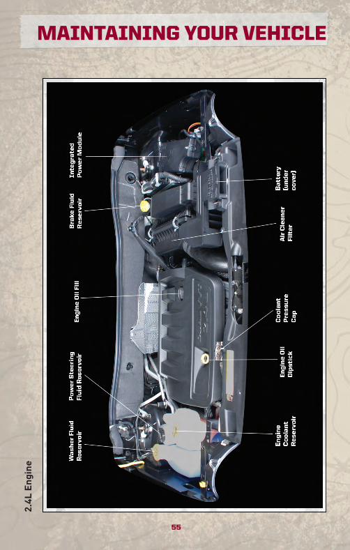
2.4L
Engine
55
MAINTAINING YOUR VEHICLE
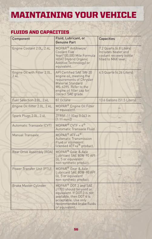
FLUIDS AND CAPACITIESComponent Fluid, Lubricant, or
Genuine PartCapacities
Engine Coolant 2.0L, 2.4L MOPAR® Antifreeze/Coolant FiveYear/100,000 Mile FormulaHOAT (Hybrid OrganicAdditive Technology) orequivalent.
7.2 Quarts (6.8 Liters)Includes heater andcoolant recovery bottlefilled to MAX level.
Engine Oil with Filter 2.0L,2.4L
API Certified SAE 5W-20engine oil, meeting therequirements of ChryslerMaterial StandardMS-6395. Refer to theengine oil filler cap forcorrect SAE grade.
4.5 Quarts (4.26 Liters)
Fuel Selection 2.0L, 2.4L 87 Octane 13.6 Gallons (51.5 Liters)
Engine Oil Filter 2.0L, 2.4L MOPAR® Engine Oil Filteror equivalent. —
Spark Plugs 2.0L, 2.4L ZFR5F-11 (Gap 0.043 in[1.11 mm]) —
Automatic Transaxle (CVT) MOPAR® CVTF + 4®Automatic Transaxle Fluid. —
Manual Transaxle MOPAR® ATF+4®Automatic TransmissionFluid or equivalentlicensed ATF+4® product.
—
Rear Drive Assembly (RDA) MOPAR® Gear & AxleLubricant SAE 80W-90 APIGL 5 or equivalentnon-synthetic product.
—
Power Transfer Unit (PTU) MOPAR® Gear & AxleLubricant SAE 80W-90 APIGL 5 or equivalentnon-synthetic product.
—
Brake Master Cylinder MOPAR® DOT 3 and SAEJ1703 should be used orequivalent. If DOT 3 is notavailable, then DOT 4 isacceptable. Use onlyrecommended brake fluidsor equivalent.
—
MAINTAINING YOUR VEHICLE
56
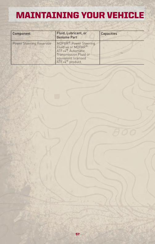
Component Fluid, Lubricant, orGenuine Part
Capacities
Power Steering Reservoir MOPAR® Power SteeringFluid +4 or MOPAR®ATF+4® AutomaticTransmission Fluid orequivalent licensedATF+4® product.
—
57
MAINTAINING YOUR VEHICLE
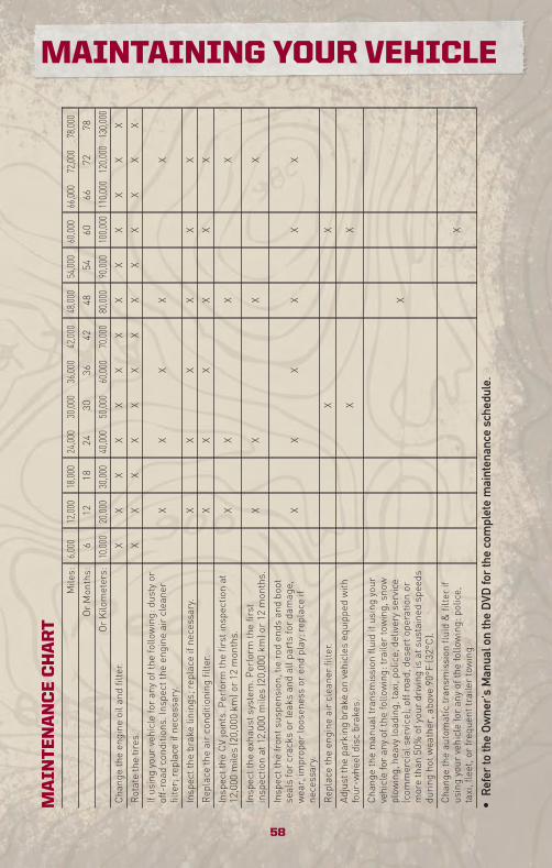
MA
INT
EN
AN
CE
CH
AR
TMiles:
6,000
12,000
18,000
24,000
30,000
36,000
42,000
48,000
54,000
60,000
66,000
72,000
78,000
OrMonths:
612
1824
3036
4248
5460
6672
78
OrKilometers:
10,000
20,000
30,000
40,000
50,000
60,000
70,000
80,000
90,000
100,000
110,000
120,000
130,000
Changetheengine
oiland
filter.
XX
XX
XX
XX
XX
XX
X
Rotatethetires.
XX
XX
XX
XX
XX
XX
X
Ifusingyour
vehicleforanyofthefollowing:dustyor
off-road
conditions.Inspectthe
engine
aircleaner
filter;replaceifnecessary.
XX
XX
X
Inspectthe
brakelinings;replace
ifnecessary.
XX
XX
XX
Replace
theairconditioningfilter.
XX
XX
XX
Inspectthe
CVjoints.Perform
thefirstinspectionat
12,000
miles(20,000km
)or12
months.
XX
XX
Inspectthe
exhaustsystem.Perform
thefirst
inspectionat12,000
miles(20,000km
)or12
months.
XX
XX
Inspectthe
frontsuspension,tie
rodends
andboot
sealsforcracks
orleaksandallpartsfordamage,
wear,improper
loosenessor
endplay;replace
ifnecessary.
XX
XX
XX
Replace
theengine
aircleanerfilter.
XX
Adjusttheparkingbrakeon
vehicles
equipped
with
four-wheeldisc
brakes.
XX
Changethemanualtransmission
fluidifusingyour
vehicleforanyofthefollowing:trailertowing,snow
plow
ing,heavyloading,taxi,police,deliveryservice
(com
mercialservice),offroad,desertoperationor
morethan
50%ofyour
drivingisatsustainedspeeds
during
hotw
eather,above
90°F
(32°C).
X
Changetheautomatictransm
ission
fluid&filterif
usingyour
vehicleforanyofthefollowing:police,
taxi,fleet,orfrequenttrailertowing.
X
•R
efer
toth
eO
wne
r's
Man
ualo
nth
eD
VDfo
rth
eco
mpl
ete
mai
nten
ance
sche
dule
.
58
MAINTAINING YOUR VEHICLE
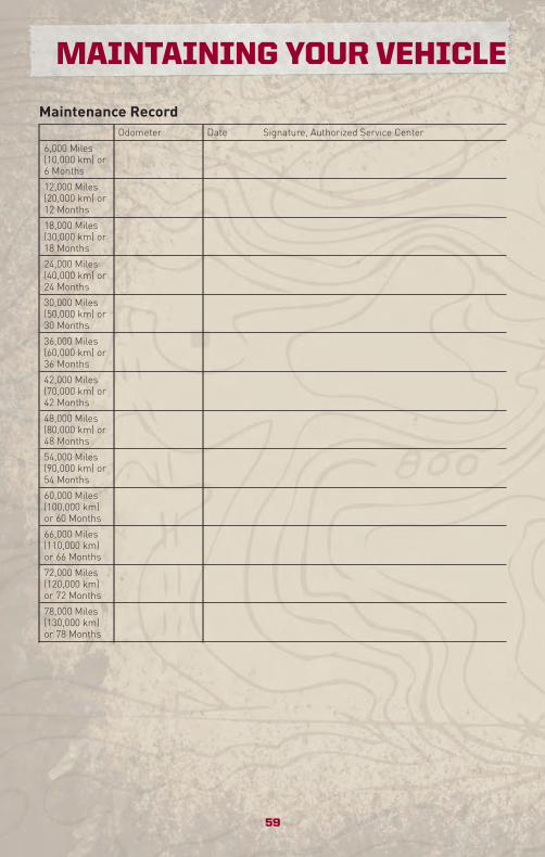
Maintenance RecordOdometer Date Signature, Authorized Service Center
6,000 Miles(10,000 km) or6 Months
12,000 Miles(20,000 km) or12 Months
18,000 Miles(30,000 km) or18 Months
24,000 Miles(40,000 km) or24 Months
30,000 Miles(50,000 km) or30 Months
36,000 Miles(60,000 km) or36 Months
42,000 Miles(70,000 km) or42 Months
48,000 Miles(80,000 km) or48 Months
54,000 Miles(90,000 km) or54 Months
60,000 Miles(100,000 km)or 60 Months
66,000 Miles(110,000 km)or 66 Months
72,000 Miles(120,000 km)or 72 Months
78,000 Miles(130,000 km)or 78 Months
59
MAINTAINING YOUR VEHICLE
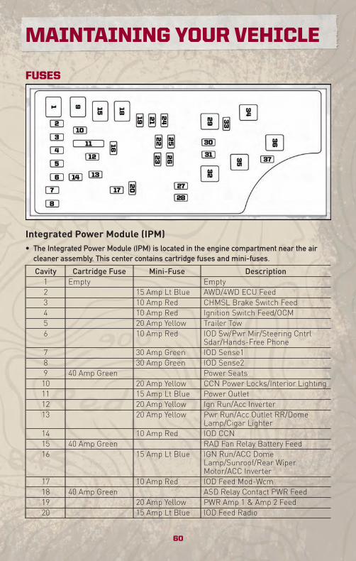
FUSES
Integrated Power Module (IPM)• The Integrated Power Module (IPM) is located in the engine compartment near the air
cleaner assembly. This center contains cartridge fuses and mini-fuses.
Cavity Cartridge Fuse Mini-Fuse Description1 Empty Empty2 15 Amp Lt Blue AWD/4WD ECU Feed3 10 Amp Red CHMSL Brake Switch Feed4 10 Amp Red Ignition Switch Feed/OCM5 20 Amp Yellow Trailer Tow6 10 Amp Red IOD Sw/Pwr Mir/Steering Cntrl
Sdar/Hands-Free Phone7 30 Amp Green IOD Sense18 30 Amp Green IOD Sense29 40 Amp Green Power Seats10 20 Amp Yellow CCN Power Locks/Interior Lighting11 15 Amp Lt Blue Power Outlet12 20 Amp Yellow Ign Run/Acc Inverter13 20 Amp Yellow Pwr Run/Acc Outlet RR/Dome
Lamp/Cigar Lighter14 10 Amp Red IOD CCN15 40 Amp Green RAD Fan Relay Battery Feed16 15 Amp Lt Blue IGN Run/ACC Dome
Lamp/Sunroof/Rear WiperMotor/ACC Inverter
17 10 Amp Red IOD Feed Mod-Wcm18 40 Amp Green ASD Relay Contact PWR Feed19 20 Amp Yellow PWR Amp 1 & Amp 2 Feed20 15 Amp Lt Blue IOD Feed Radio
MAINTAINING YOUR VEHICLE
60
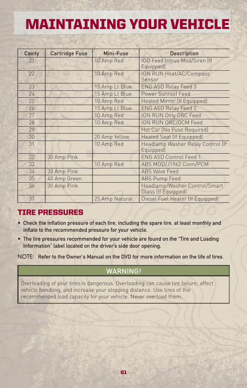
Cavity Cartridge Fuse Mini-Fuse Description21 10 Amp Red IOD Feed Intrus Mod/Siren (If
Equipped)22 10 Amp Red IGN RUN Heat/AC/Compass
Sensor23 15 Amp Lt Blue ENG ASD Relay Feed 324 15 Amp Lt Blue Power Sunroof Feed25 10 Amp Red Heated Mirror (If Equipped)26 15 Amp Lt Blue ENG ASD Relay Feed 227 10 Amp Red IGN RUN Only ORC Feed28 10 Amp Red IGN RUN ORC/OCM Feed29 Hot Car (No Fuse Required)30 20 Amp Yellow Heated Seat (If Equipped)31 10 Amp Red Headlamp Washer Relay Control (If
Equipped)32 30 Amp Pink ENG ASD Control Feed 133 10 Amp Red ABS MOD/J1962 Conn/PCM34 30 Amp Pink ABS Valve Feed35 40 Amp Green ABS Pump Feed36 30 Amp Pink Headlamp/Washer Control/Smart
Glass (If Equipped)37 25 Amp Natural Diesel Fuel Heater (If Equipped)
TIRE PRESSURES• Check the inflation pressure of each tire, including the spare tire, at least monthly and
inflate to the recommended pressure for your vehicle.
• The tire pressures recommended for your vehicle are found on the “Tire and LoadingInformation” label located on the driver’s side door opening.
NOTE: Refer to the Owner's Manual on the DVD for more information on the life of tires.
WARNING!
Overloading of your tires is dangerous. Overloading can cause tire failure, affectvehicle handling, and increase your stopping distance. Use tires of therecommended load capacity for your vehicle. Never overload them.
61
MAINTAINING YOUR VEHICLE
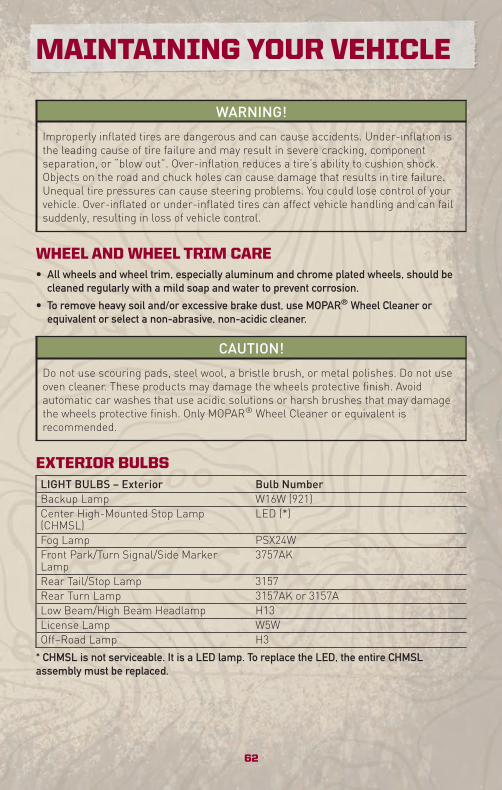
WARNING!
Improperly inflated tires are dangerous and can cause accidents. Under-inflation isthe leading cause of tire failure and may result in severe cracking, componentseparation, or “blow out”. Over-inflation reduces a tire’s ability to cushion shock.Objects on the road and chuck holes can cause damage that results in tire failure.Unequal tire pressures can cause steering problems. You could lose control of yourvehicle. Over-inflated or under-inflated tires can affect vehicle handling and can failsuddenly, resulting in loss of vehicle control.
WHEEL AND WHEEL TRIM CARE• All wheels and wheel trim, especially aluminum and chrome plated wheels, should be
cleaned regularly with a mild soap and water to prevent corrosion.
• To remove heavy soil and/or excessive brake dust, use MOPAR® Wheel Cleaner orequivalent or select a non-abrasive, non-acidic cleaner.
CAUTION!
Do not use scouring pads, steel wool, a bristle brush, or metal polishes. Do not useoven cleaner. These products may damage the wheels protective finish. Avoidautomatic car washes that use acidic solutions or harsh brushes that may damagethe wheels protective finish. Only MOPAR® Wheel Cleaner or equivalent isrecommended.
EXTERIOR BULBSLIGHT BULBS – Exterior Bulb NumberBackup Lamp W16W (921)Center High-Mounted Stop Lamp(CHMSL)
LED (*)
Fog Lamp PSX24WFront Park/Turn Signal/Side MarkerLamp
3757AK
Rear Tail/Stop Lamp 3157Rear Turn Lamp 3157AK or 3157ALow Beam/High Beam Headlamp H13License Lamp W5WOff–Road Lamp H3
* CHMSL is not serviceable. It is a LED lamp. To replace the LED, the entire CHMSLassembly must be replaced.
MAINTAINING YOUR VEHICLE
62
CHRYSLER GROUP LLCCUSTOMER CENTERP.O. Box 21–8004
Auburn Hills, MI 48321–8004
Phone: 1–800–992–1997
CHRYSLER CANADA INC.CUSTOMER CENTERP.O. Box 1621
Windsor, Ontario N9A 4H6
Phone: 1–800–465–2001
ASSISTANCE FOR THEHEARING IMPAIRED• To assist customers who have hearing
difficulties, the manufacturer hasinstalled special TDD(Telecommunication Devices for theDeaf) equipment at its customer center.Any hearing or speech impairedcustomer, who has access to a TDD ora conventional teletypewriter (TTY) inthe United States, can communicatewith the manufacturer by dialing1–800–380–CHRY. Canadian residentswith hearing difficulties that requireassistance can use the special needsrelay service offered by Bell Canada.For TTY teletypewriter users, dial 711and for Voice callers, dial1–800–855–0511 to connect with a BellRelay Service operator.
WARNING!
Engine exhaust, some of itsconstituents, and certain vehiclecomponents contain, or emit,chemicals known to the State ofCalifornia to cause cancer and birthdefects, or other reproductive harm.In addition, certain fluids containedin vehicles and certain products ofcomponent wear contain, or emit,chemicals known to the State ofCalifornia to cause cancer and birthdefects, or other reproductive harm.
PUBLICATIONSORDERING• If you are the first registered retail
owner of your vehicle, you may obtain afree printed copy of the Owner'sManual, Warranty Booklet or RadioManuals on your DVD by calling1–800–992–1997 (U.S.) or1–800–387–1143 (Canada) or bycontacting your dealer.
• Replacement User Guides or DVDs or,if you prefer, a printed copy of theOwner's Manual, Warranty Booklet orRadio Manuals may be purchased byvisiting www.techauthority.com or bycalling 1–800–890–4038 (U.S.) or1–800–387–1143 (Canada). Visa, MasterCard, American Express and Discoverorders are accepted. If you prefermailing your order, please call theabove numbers for an order form.
NOTE: A street address is requiredwhen ordering manuals (no P.O. Boxes).
63
CONSUMER ASSISTANCE
REPORTING SAFETYDEFECTS IN THE 50UNITED STATES ANDWASHINGTON, D.C.• If you believe that your vehicle has a
defect that could cause a crash orcause injury or death, you shouldimmediately inform the NationalHighway Traffic Safety Administration(NHTSA) in addition to notifying themanufacturer.
• If NHTSA receives similar complaints,it may open an investigation, and if itfinds that a safety defect exists in agroup of vehicles, it may order a recalland remedy campaign. However,NHTSA cannot become involved inindividual problems between you, yourauthorized dealer, and themanufacturer.
• To contact NHTSA, you may either callthe Auto Safety Hotline toll free at1–888–327–4236 (TTY: 1–800–424–9153), or go to http://www.safercar.gov;or write to: Administrator, NHTSA, 1200New Jersey Avenue, SE., WestBuilding, Washington, D.C. 20590. Youcan also obtain other information aboutmotor vehicle safety fromhttp://www.safercar.gov.
In Canada• If you believe that your vehicle has a
safety defect, you should contact theCustomer Service Departmentimmediately. Canadian customers whowish to report a safety defect to theCanadian government should write to:Transport Canada, Motor Vehicle DefectInvestigations and Recalls,2780 Sheffield Road, Ottawa,Ontario K1B 3V9.
TIRE WARRANTY
Tire Limited Warranty AndAdjustment Policy• When a tire is removed from service
due to a covered warranty conditionunder a tire manufacturer’s “LimitedWarranty Program”, you may beeligible for a free tire replacement or acomparable new tire on a “proratedbasis”.
• Certain conditions, such as irregularwear or tire damage due to roadhazards, collision, improper inflation,intentional alteration, and misuse, areexcluded from the Limited WarrantyProgram. The Limited WarrantyProgram expires when your tires eitherwear to a specified tread depth, and/orafter a period of time from the date ofpurchase, as stated in the TireWarranty on the DVD.
NOTE: Refer to the Tire Warranty onthe DVD for specific informationrelating to the manufacturer's limitedwarranty for the tires installed onyour vehicle. If you have anyquestions regarding the limited tirewarranty coverage, contact yourlocal authorized dealer or your localauthorized tire dealer.
CONSUMER ASSISTANCE
64
Disclaimer:
• THE TIRE MANUFACTURER’S LIMITEDWARRANTY PROGRAM, THE DETAILSOF WHICH CAN BE FOUND, ON THEOWNERS MANUAL DVD, THE TIREMANUFACTURER’S WEBSITE OR ATANY AUTHORIZED SERVICE CENTERARE IN LIEU OF ALL OTHER REMEDIESOR WARRANTIES, EXPRESS ORIMPLIED, ARISING BY LAW OROTHERWISE, INCLUDING FITNESS FORA PARTICULAR PURPOSE ORMERCHANTABILITY. THE TIREMANUFACTURER EXPRESSLYDISCLAIMS LIABILITY FOR INDIRECT,SPECIAL, INCIDENTAL ORCONSEQUENTIAL DAMAGES, LOSTPROFIT, LOSS OF BUSINESS, LOSS OFGOODWILL, LOSS OF REPUTATION,PUNITIVE OR ANY OTHER DAMAGE,COST OR LOSS OF ANY KIND. SOMESTATES AND PROVINCES DO NOTALLOW THE EXCLUSION ORLIMITATION OF INCIDENTAL ORCONSEQUENTIAL DAMAGES, SO THEABOVE LIMITATION OR EXCLUSIONMAY NOT APPLY TO YOU.
WARNING!
NOTE: Refer to the Owner’s Manualon the DVD for complete warninginformation that could preventaccidents, injuries and even deaths.
WARNING!
Death, serious injury and/or propertydamage may result from:• Tire failure due to impact damageand/or improper maintenance.
(Continued)
WARNING! (Continued)
• Tires should be inspectedregularly by a qualified technicianfor signs of damage, such aspunctures, impacts,under-inflation or overloading.
• Progressive air loss may resultfrom punctures, cuts, curbing,impacts or partial bead unseating.
Some fitment causes for air loss are:• Incomplete bead seating.• Bead tearing caused by a machinetool due to insufficient lubricationor improper adjustment.
• Leaking valve core or rubber valvecomponents (these should bereplaced when problems aredetected and whenever tires arereplaced).
• Tire failure due to improperrepairs.
• See Rubber Manufacturer’sAssociation (RMA) establishedrepair procedures at www.rma.orgfor information on proper repairprocedures. Never perform atemporary repair or use an innertube as a substitute for a properrepair. Only qualified personsshould repair tires.
• Explosion of tire/rim assembly dueto improper mounting.
• Only specially trained personsshould mount tires.
• Failure to mount tires on approvedrims.
• Failure to deflate single or dualassemblies completely beforedemounting.
65
CONSUMER ASSISTANCE
Using Lift Kits• Use of lift kits with some vehicle/tire
combinations can cause instability orloss of control. When changing tiresizes, always consult an installer foroptimum rim width and carefully checkvehicle/tire clearances.
Check Your Tires For Damage• Frequent (at least monthly) inspection
of your tires for signs of damage,uneven tread wear and their generalcondition is important for safety.Impacts, penetrations, cracks, knots,bulges or air loss always require tireremoval and expert inspection.
Tire Service Life• The service life of a tire is dependent
upon varying factors including, but notlimited to, your driving style, tirepressure and distance driven.
WARNING!
Tires and the spare tire should bereplaced after six years, regardlessof the remaining tread. Failure tofollow this warning can result insudden tire failure. You could losecontrol and have an accidentresulting in serious injury or death.
• Keep dismounted tires in a cool, dryplace with as little exposure to the lightas possible.
• Protect tires from contact with oil,grease, and gasoline.
NOTE: All tire warranties are made bythe tire manufacturer. Tires are notcovered under your Chrysler New VehicleLimited Warranty.
CONSUMER ASSISTANCE
66
MOPAR® ACCESSORIES• The following highlights just some of the authentic Jeep Accessories by MOPAR® that
have been engineered to customize your Jeep Patriot.
• To see the full line of accessories, stop by your Jeep dealer or visit MOPAR.com.
EXTERIOR:• Driving Lights • Sunroof Air Deflector • Front Air Deflector• Hitch Receiver • Front End and Hood
Cover• Molded Splash Guards
• Fog Lights • Side Window AirDeflectors
• Off Road Lights
INTERIOR:• Premium Carpet FloorMats
• Door Sill Guards • Bright Pedal Kit
• Slush Mats • Ambient Light Kit • Heated Seats
ELECTRONICS:• Portable NavigationSystems
• uconnect™ web (WiFi) • uconnect™ phone
• iPod® Adapter • uconnect™ tunes (RENRadio)
• DVD Rear Seat Video™
• Kicker® Sound System • uconnect™ gps (RERRadio)
• Remote Start
CARRIERS:• Hitch-mount BikeCarrier
• Roof Mount Bike Carrier • Roof Box Cargo Carrier
• Roof Mount Ski andSnowboard Carrier
• Roof Mount Water SportsCarrier
• Roof Mount CanoeCarrier
• iPod® is a registered trademark of Apple, Inc.
• Kicker® is a registered trademark of Stillwater Designs and Audio, Inc.
67
MOPAR ACCESSORIES

NOTES
68

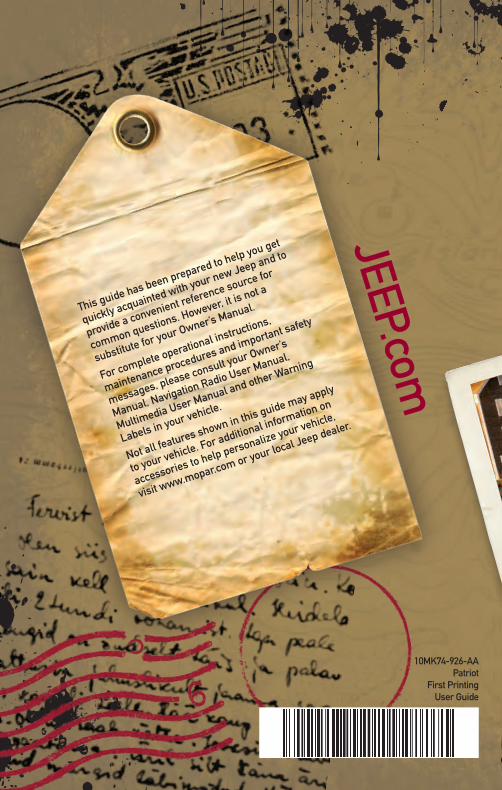
This guide has been prepared to help you get
quickly acquainted with your new Jeep and to
provide a convenient reference source for
common questions. However, it is not a
substitute for your Owner’s Manual.
For complete operational instructions,
maintenance procedures and important safety
messages, please consult your Owner’s
Manual, Navigation Radio User Manual,
Multimedia User Manual and other Warning
Labels in your vehicle.
Not all features shown in this guide may apply
to your vehicle. For additional information on
accessories to help personalize your vehicle,
visit www.mopar.com or your local Jeep dealer.
JEEP.com
10MK74-926-AAPatriot
First PrintingUser Guide