Embed Size (px)
Citation preview
BODY / STEERING / SUSPENSION
5.1
CHAPTER 5
BODY / STEERING / SUSPENSION
5
TORQUE SPECIFICATIONS. . . . . . . . . . . . . . . . . . . . . . . . . . . . . . . . . . . . . . . . . . . . . . . 5.2SPECIAL TOOLS . . . . . . . . . . . . . . . . . . . . . . . . . . . . . . . . . . . . . . . . . . . . . . . . . . . . . . . 5.2CHASSIS / MAIN FRAME . . . . . . . . . . . . . . . . . . . . . . . . . . . . . . . . . . . . . . . . . . . . . . . . . 5.3CAB FRAME / SEAT BACK / HEADREST / PVT AIR INTAKE BAFFLE BOX . . . . . . . . . 5.6BODY EXPLODED VIEWS . . . . . . . . . . . . . . . . . . . . . . . . . . . . . . . . . . . . . . . . . . . . . . . . 5.8
DASH INSTRUMENTS / CONTROLS . . . . . . . . . . . . . . . . . . . . . . . . . . . . . . . . . . . . . . . 5.8HOOD / DASH / FRONT FENDERS / FRONT FASCIA . . . . . . . . . . . . . . . . . . . . . . . . . . 5.92011 FLOOR / REAR FENDERS (XP / HD / 6X6) . . . . . . . . . . . . . . . . . . . . . . . . . . . . . 5.102012 FLOOR / REAR FENDERS (XP / HD / 6X6) . . . . . . . . . . . . . . . . . . . . . . . . . . . . . 5.112011 FLOOR / REAR FENDERS (CREW). . . . . . . . . . . . . . . . . . . . . . . . . . . . . . . . . . . 5.122012 FLOOR / REAR FENDERS (CREW). . . . . . . . . . . . . . . . . . . . . . . . . . . . . . . . . . . 5.13SEAT MOUNTING / SEAT BELTS (XP / HD / 6X6) . . . . . . . . . . . . . . . . . . . . . . . . . . . . 5.14SEAT MOUNTING / SEAT BELTS (CREW). . . . . . . . . . . . . . . . . . . . . . . . . . . . . . . . . . 5.15
REAR CARGO BOX . . . . . . . . . . . . . . . . . . . . . . . . . . . . . . . . . . . . . . . . . . . . . . . . . . . . 5.16CARGO BOX - PANELS. . . . . . . . . . . . . . . . . . . . . . . . . . . . . . . . . . . . . . . . . . . . . . . . . 5.16CARGO BOX - TAILGATE / BOX SUPPORT. . . . . . . . . . . . . . . . . . . . . . . . . . . . . . . . . 5.17BOX REMOVAL . . . . . . . . . . . . . . . . . . . . . . . . . . . . . . . . . . . . . . . . . . . . . . . . . . . . . . . 5.18BOX INSTALLATION . . . . . . . . . . . . . . . . . . . . . . . . . . . . . . . . . . . . . . . . . . . . . . . . . . . 5.19
REAR STORAGE BOX (6X6) . . . . . . . . . . . . . . . . . . . . . . . . . . . . . . . . . . . . . . . . . . . . . 5.20BODY COMPONENT REMOVAL . . . . . . . . . . . . . . . . . . . . . . . . . . . . . . . . . . . . . . . . . . 5.21
LOWER SEAT BASE / WHEEL WELL PANELS / FRONT BUMPER / FASCIA . . . . . . 5.21FRONT FENDERS / HOOD / DASH / GLOVE BOX / STORAGE PANEL . . . . . . . . . . . 5.22REAR FENDERS / FLOOR (XP / HD / 6X6). . . . . . . . . . . . . . . . . . . . . . . . . . . . . . . . . . 5.23MID / REAR FENDERS / FLOOR (CREW) . . . . . . . . . . . . . . . . . . . . . . . . . . . . . . . . . . 5.24
STEERING ASSEMBLY . . . . . . . . . . . . . . . . . . . . . . . . . . . . . . . . . . . . . . . . . . . . . . . . . 5.25STEERING WHEEL / SHAFT REMOVAL (NON-EPS MODELS) . . . . . . . . . . . . . . . . . 5.26STEERING SHAFT BEARING REPLACEMENT . . . . . . . . . . . . . . . . . . . . . . . . . . . . . . 5.27
POWER STEERING ASSEMBLY (EPS) . . . . . . . . . . . . . . . . . . . . . . . . . . . . . . . . . . . . . 5.28STEERING WHEEL REMOVAL (EPS MODELS) . . . . . . . . . . . . . . . . . . . . . . . . . . . . . 5.29POWER STEERING UNIT REMOVAL. . . . . . . . . . . . . . . . . . . . . . . . . . . . . . . . . . . . . . 5.29POWER STEERING UNIT INSTALLATION. . . . . . . . . . . . . . . . . . . . . . . . . . . . . . . . . . 5.31
FRONT A-ARMS . . . . . . . . . . . . . . . . . . . . . . . . . . . . . . . . . . . . . . . . . . . . . . . . . . . . . . . 5.32BALL JOINT SERVICE . . . . . . . . . . . . . . . . . . . . . . . . . . . . . . . . . . . . . . . . . . . . . . . . . . 5.34MID / REAR A-ARMS . . . . . . . . . . . . . . . . . . . . . . . . . . . . . . . . . . . . . . . . . . . . . . . . . . . 5.36REAR STABILIZER BAR / LINKAGE . . . . . . . . . . . . . . . . . . . . . . . . . . . . . . . . . . . . . . . 5.39DECAL REPLACEMENT. . . . . . . . . . . . . . . . . . . . . . . . . . . . . . . . . . . . . . . . . . . . . . . . . 5.40SHOCKS / SPRINGS. . . . . . . . . . . . . . . . . . . . . . . . . . . . . . . . . . . . . . . . . . . . . . . . . . . . 5.41
EXPLODED VIEW (STANDARD) / (WALKER EVANS™) . . . . . . . . . . . . . . . . . . . . . . . 5.41SHOCK REMOVAL / INSTALLATION / REPLACEMENT . . . . . . . . . . . . . . . . . . . . . . . 5.41
SELF-LEVELING SUSPENSION (HD) . . . . . . . . . . . . . . . . . . . . . . . . . . . . . . . . . . . . . . 5.42NIVOMAT® SHOCK OPERATION / DISPOSAL / REPLACEMENT . . . . . . . . . . . . . . . 5.42
WALKER EVANS™ SHOCK EXPLODED VIEW . . . . . . . . . . . . . . . . . . . . . . . . . . . . . . 5.43WALKER EVANS™ SHOCK SERVICE . . . . . . . . . . . . . . . . . . . . . . . . . . . . . . . . . . . . . 5.44
RECOMMENDED SERVICE INTERVALS . . . . . . . . . . . . . . . . . . . . . . . . . . . . . . . . . . . 5.44FRONT / REAR SHOCK SERVICE INFORMATION . . . . . . . . . . . . . . . . . . . . . . . . . . . 5.44WALKER EVANS™ SHOCK REBUILD INFORMATION . . . . . . . . . . . . . . . . . . . . . . . . 5.45SPECIAL TOOLS . . . . . . . . . . . . . . . . . . . . . . . . . . . . . . . . . . . . . . . . . . . . . . . . . . . . . . 5.45VALVE SHIM ARRANGEMENT . . . . . . . . . . . . . . . . . . . . . . . . . . . . . . . . . . . . . . . . . . . 5.45PISTON ORIENTATION. . . . . . . . . . . . . . . . . . . . . . . . . . . . . . . . . . . . . . . . . . . . . . . . . 5.45WALKER EVANS™ SHOCK DISASSEMBLY . . . . . . . . . . . . . . . . . . . . . . . . . . . . . . . . 5.46WALKER EVANS™ SHOCK ASSEMBLY . . . . . . . . . . . . . . . . . . . . . . . . . . . . . . . . . . . 5.48
9923499 - 2011 / 2012 RANGER 800 Service Manual© Copyright 2011 Polaris Sales Inc.
BODY / STEERING / SUSPENSION
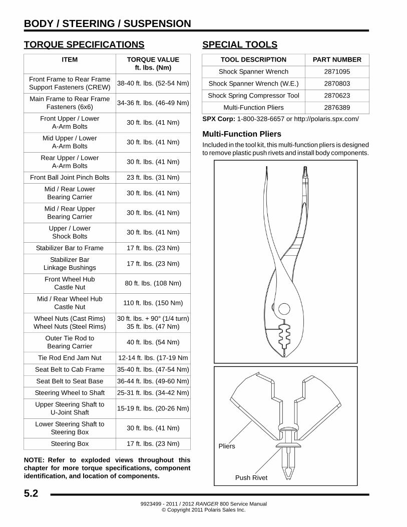
TORQUE SPECIFICATIONS
NOTE: Refer to exploded views throughout this chapter for more torque specifications, component identification, and location of components.
SPECIAL TOOLS
SPX Corp: 1-800-328-6657 or http://polaris.spx.com/
Multi-Function PliersIncluded in the tool kit, this multi-function pliers is designed to remove plastic push rivets and install body components.
ITEM TORQUE VALUEft. lbs. (Nm)
Front Frame to Rear Frame Support Fasteners (CREW)
38-40 ft. lbs. (52-54 Nm)
Main Frame to Rear Frame Fasteners (6x6)
34-36 ft. lbs. (46-49 Nm)
Front Upper / LowerA-Arm Bolts
30 ft. lbs. (41 Nm)
Mid Upper / LowerA-Arm Bolts
30 ft. lbs. (41 Nm)
Rear Upper / LowerA-Arm Bolts
30 ft. lbs. (41 Nm)
Front Ball Joint Pinch Bolts 23 ft. lbs. (31 Nm)
Mid / Rear LowerBearing Carrier
30 ft. lbs. (41 Nm)
Mid / Rear UpperBearing Carrier
30 ft. lbs. (41 Nm)
Upper / LowerShock Bolts
30 ft. lbs. (41 Nm)
Stabilizer Bar to Frame 17 ft. lbs. (23 Nm)
Stabilizer BarLinkage Bushings
17 ft. lbs. (23 Nm)
Front Wheel HubCastle Nut
80 ft. lbs. (108 Nm)
Mid / Rear Wheel HubCastle Nut
110 ft. lbs. (150 Nm)
Wheel Nuts (Cast Rims)Wheel Nuts (Steel Rims)
30 ft. lbs. + 90° (1/4 turn)35 ft. lbs. (47 Nm)
Outer Tie Rod toBearing Carrier
40 ft. lbs. (54 Nm)
Tie Rod End Jam Nut 12-14 ft. lbs. (17-19 Nm
Seat Belt to Cab Frame 35-40 ft. lbs. (47-54 Nm)
Seat Belt to Seat Base 36-44 ft. lbs. (49-60 Nm)
Steering Wheel to Shaft 25-31 ft. lbs. (34-42 Nm)
Upper Steering Shaft to U-Joint Shaft
15-19 ft. lbs. (20-26 Nm)
Lower Steering Shaft to Steering Box
30 ft. lbs. (41 Nm)
Steering Box 17 ft. lbs. (23 Nm)
TOOL DESCRIPTION PART NUMBER
Shock Spanner Wrench 2871095
Shock Spanner Wrench (W.E.) 2870803
Shock Spring Compressor Tool 2870623
Multi-Function Pliers 2876389
Pliers
Push Rivet
5.29923499 - 2011 / 2012 RANGER 800 Service Manual
© Copyright 2011 Polaris Sales Inc.
BODY / STEERING / SUSPENSION
5
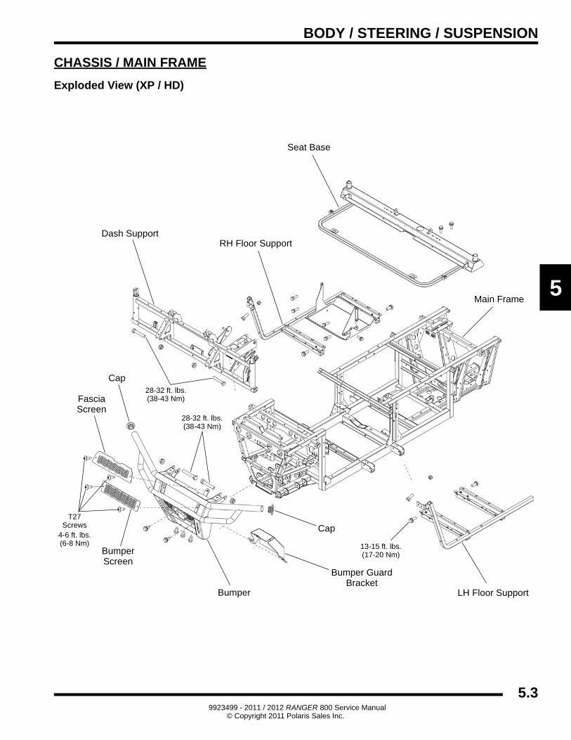
CHASSIS / MAIN FRAME
Exploded View (XP / HD)
Seat Base
Dash Support
Bumper LH Floor Support
RH Floor Support
Main Frame
Cap
Cap
FasciaScreen
BumperScreen
Bumper GuardBracket
T27Screws
28-32 ft. lbs.(38-43 Nm)
28-32 ft. lbs.(38-43 Nm)
4-6 ft. lbs.(6-8 Nm) 13-15 ft. lbs.
(17-20 Nm)
5.39923499 - 2011 / 2012 RANGER 800 Service Manual
© Copyright 2011 Polaris Sales Inc.
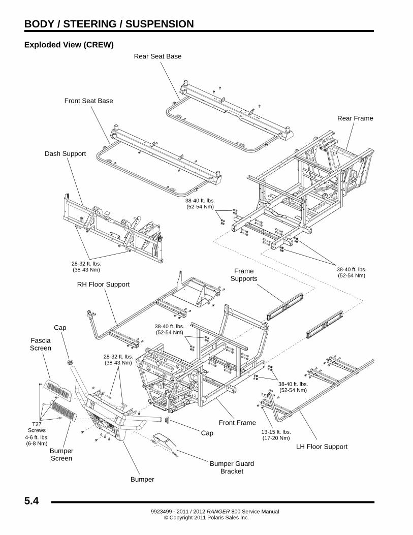
BODY / STEERING / SUSPENSION
Exploded View (CREW)Rear Seat Base
Dash Support
Bumper
LH Floor Support
RH Floor Support
Rear Frame
Cap
Cap
FasciaScreen
BumperScreen
Bumper GuardBracket
T27Screws
28-32 ft. lbs.(38-43 Nm)
28-32 ft. lbs.(38-43 Nm)
4-6 ft. lbs.(6-8 Nm)
13-15 ft. lbs.(17-20 Nm)
Front Seat Base
38-40 ft. lbs.(52-54 Nm)
38-40 ft. lbs.(52-54 Nm)
Frame
38-40 ft. lbs.(52-54 Nm)
38-40 ft. lbs.(52-54 Nm)
Supports
Front Frame
5.49923499 - 2011 / 2012 RANGER 800 Service Manual
© Copyright 2011 Polaris Sales Inc.
BODY / STEERING / SUSPENSION
5
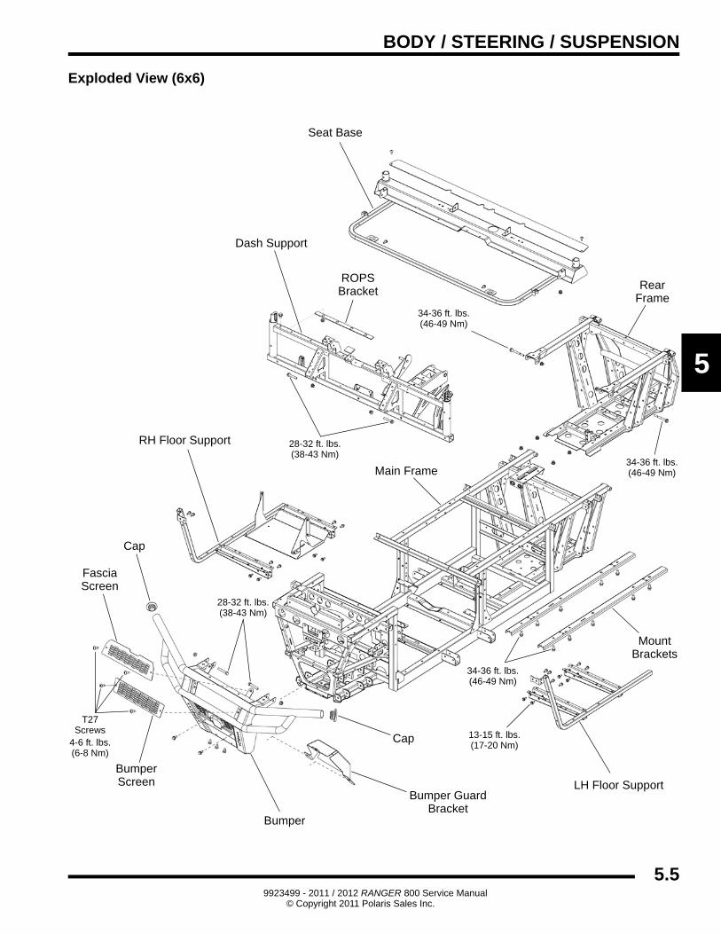
Exploded View (6x6)
Seat Base
Dash Support
Bumper
LH Floor Support
RH Floor Support
Main Frame
Cap
Cap
FasciaScreen
BumperScreen
Bumper GuardBracket
T27Screws
28-32 ft. lbs.(38-43 Nm)
28-32 ft. lbs.(38-43 Nm)
4-6 ft. lbs.(6-8 Nm)
13-15 ft. lbs.(17-20 Nm)
RearFrame
34-36 ft. lbs.(46-49 Nm)
34-36 ft. lbs.(46-49 Nm)
MountBrackets
34-36 ft. lbs.(46-49 Nm)
ROPSBracket
5.59923499 - 2011 / 2012 RANGER 800 Service Manual
© Copyright 2011 Polaris Sales Inc.
BODY / STEERING / SUSPENSION
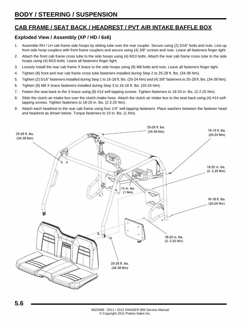
CAB FRAME / SEAT BACK / HEADREST / PVT AIR INTAKE BAFFLE BOX
Exploded View / Assembly (XP / HD / 6x6)
1. Assemble RH / LH cab frame side hoops by sliding tube over the rear coupler. Secure using (2) 5/16” bolts and nuts. Line up front side hoop couplers with front frame couplers and secure using (4) 3/8” screws and nuts. Leave all fasteners finger tight.
2. Attach the front cab frame cross tube to the side hoops using (4) M10 bolts. Attach the rear cab frame cross tube to the side hoops using (4) M10 bolts. Leave all fasteners finger tight.
3. Loosely install the rear cab frame X brace to the side hoops using (8) M8 bolts and nuts. Leave all fasteners finger tight.
4. Tighten (8) front and rear cab frame cross tube fasteners installed during Step 2 to 25-28 ft. lbs. (34-38 Nm).
5. Tighten (2) 5/16” fasteners installed during Step 1 to 16-18 ft. lbs. (20-24 Nm) and (4) 3/8” fasteners to 25-28 ft. lbs. (34-38 Nm).
6. Tighten (8) M8 X brace fasteners installed during Step 3 to 16-18 ft. lbs. (20-24 Nm).
7. Fasten the seat back to the X brace using (8) #14 self-tapping screws. Tighten fasteners to 18-20 in. lbs. (2-2.25 Nm).
8. Slide the clutch air intake box over the clutch intake hose. Attach the clutch air intake box to the seat back using (4) #14 self-tapping screws. Tighten fasteners to 18-20 in. lbs. (2-2.25 Nm).
9. Attach each headrest to the rear cab frame using four 1/4” self-tapping fasteners. Place washers between the fastener head and headrest as shown below. Torque fasteners to 10 in. lbs. (1 Nm).
5.69923499 - 2011 / 2012 RANGER 800 Service Manual
© Copyright 2011 Polaris Sales Inc.
BODY / STEERING / SUSPENSION
5
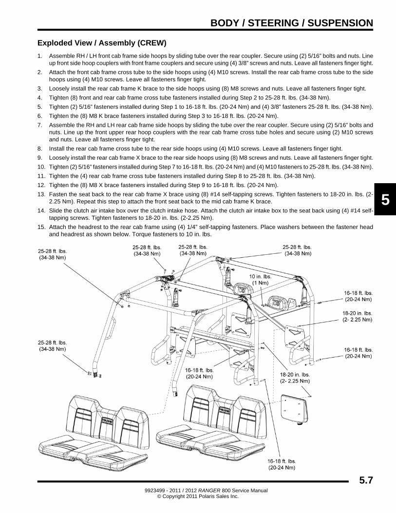
Exploded View / Assembly (CREW)
1. Assemble RH / LH front cab frame side hoops by sliding tube over the rear coupler. Secure using (2) 5/16” bolts and nuts. Line up front side hoop couplers with front frame couplers and secure using (4) 3/8” screws and nuts. Leave all fasteners finger tight.
2. Attach the front cab frame cross tube to the side hoops using (4) M10 screws. Install the rear cab frame cross tube to the side hoops using (4) M10 screws. Leave all fasteners finger tight.
3. Loosely install the rear cab frame K brace to the side hoops using (8) M8 screws and nuts. Leave all fasteners finger tight.
4. Tighten (8) front and rear cab frame cross tube fasteners installed during Step 2 to 25-28 ft. lbs. (34-38 Nm).
5. Tighten (2) 5/16” fasteners installed during Step 1 to 16-18 ft. lbs. (20-24 Nm) and (4) 3/8” fasteners 25-28 ft. lbs. (34-38 Nm).
6. Tighten the (8) M8 K brace fasteners installed during Step 3 to 16-18 ft. lbs. (20-24 Nm).
7. Assemble the RH and LH rear cab frame side hoops by sliding the tube over the rear coupler. Secure using (2) 5/16” bolts and nuts. Line up the front upper rear hoop couplers with the rear cab frame cross tube holes and secure using (2) M10 screws and nuts. Leave all fasteners finger tight.
8. Install the rear cab frame cross tube to the rear side hoops using (4) M10 screws. Leave all fasteners finger tight.
9. Loosely install the rear cab frame X brace to the rear side hoops using (8) M8 screws and nuts. Leave all fasteners finger tight.
10. Tighten (2) 5/16” fasteners installed during Step 7 to 16-18 ft. lbs. (20-24 Nm) and (4) M10 fasteners to 25-28 ft. lbs. (34-38 Nm).
11. Tighten the (4) rear cab frame cross tube fasteners installed during Step 8 to 25-28 ft. lbs. (34-38 Nm).
12. Tighten the (8) M8 X brace fasteners installed during Step 9 to 16-18 ft. lbs. (20-24 Nm).
13. Fasten the seat back to the rear cab frame X brace using (8) #14 self-tapping screws. Tighten fasteners to 18-20 in. lbs. (2-2.25 Nm). Repeat this step to attach the front seat back to the mid cab frame K brace.
14. Slide the clutch air intake box over the clutch intake hose. Attach the clutch air intake box to the seat back using (4) #14 self-tapping screws. Tighten fasteners to 18-20 in. lbs. (2-2.25 Nm).
15. Attach the headrest to the rear cab frame using (4) 1/4” self-tapping fasteners. Place washers between the fastener head and headrest as shown below. Torque fasteners to 10 in. lbs.
5.79923499 - 2011 / 2012 RANGER 800 Service Manual
© Copyright 2011 Polaris Sales Inc.
BODY / STEERING / SUSPENSION
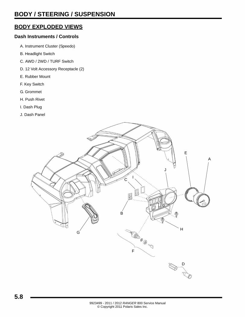
BODY EXPLODED VIEWS
Dash Instruments / Controls
C
D
E
G
A. Instrument Cluster (Speedo)
B. Headlight Switch
C. AWD / 2WD / TURF Switch
D. 12 Volt Accessory Receptacle (2)
E. Rubber Mount
F. Key Switch
G. Grommet
H. Push Rivet
I. Dash Plug
J. Dash Panel
J
F
H
I
A
B
5.89923499 - 2011 / 2012 RANGER 800 Service Manual
© Copyright 2011 Polaris Sales Inc.
BODY / STEERING / SUSPENSION
5
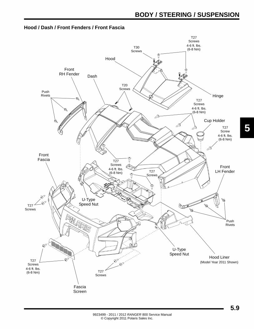
Hood / Dash / Front Fenders / Front Fascia
Dash
Hood
Cup Holder
Hood Liner
Hinge
U-TypeSpeed Nut
FrontFascia
FasciaScreen
FrontRH Fender
FrontLH Fender
T27Screw
4-6 ft. lbs.(6-8 Nm)
T27Screws
4-6 ft. lbs.(6-8 Nm)
T27Screws
4-6 ft. lbs.(6-8 Nm)
T20Screws
PushRivets
T27Screws
4-6 ft. lbs.(6-8 Nm) T27
Screws
PushRivets
U-TypeSpeed Nut
T27Screws
4-6 ft. lbs.(6-8 Nm)
T27Screws
T27Screws
T30Screws
(Model Year 2011 Shown)
5.99923499 - 2011 / 2012 RANGER 800 Service Manual
© Copyright 2011 Polaris Sales Inc.
BODY / STEERING / SUSPENSION
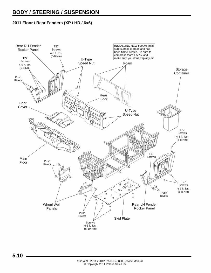
2011 Floor / Rear Fenders (XP / HD / 6x6)
Skid Plate
FloorCover
MainFloor
RearFloor
Foam
Wheel WellPanels
Rear RH FenderRocker Panel
Rear LH FenderRocker Panel
StorageContainer
U-TypeSpeed Nut
T27Screws
4-6 ft. lbs.(6-8 Nm)
PushRivets
PushRivets
PushRivets
PushRivets
T27Screws
4-6 ft. lbs.(6-8 Nm)
T27Screws
4-6 ft. lbs.(6-8 Nm)
T27Screws
4-6 ft. lbs.(6-8 Nm)
Screws6-8 ft. lbs.(8-10 Nm)
U-TypeSpeed Nut
T27Screws
INSTALLING NEW FOAM: Makesure surface is clean and hasbeen flame treated. Be sure tocompress foam > 50%, andmake sure you don’t trap any air.
5.109923499 - 2011 / 2012 RANGER 800 Service Manual
© Copyright 2011 Polaris Sales Inc.
BODY / STEERING / SUSPENSION
5
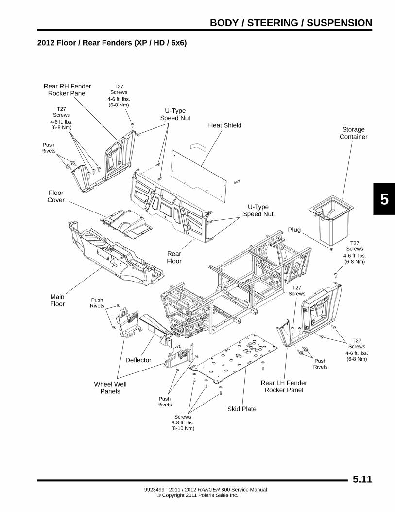
2012 Floor / Rear Fenders (XP / HD / 6x6)
Skid Plate
FloorCover
MainFloor
RearFloor
Heat Shield
Wheel WellPanels
Rear RH FenderRocker Panel
Rear LH FenderRocker Panel
StorageContainer
U-TypeSpeed Nut
T27Screws
4-6 ft. lbs.(6-8 Nm)
PushRivets
PushRivets
PushRivets
PushRivets
T27Screws
4-6 ft. lbs.(6-8 Nm)
T27Screws
4-6 ft. lbs.(6-8 Nm)
T27Screws
4-6 ft. lbs.(6-8 Nm)
Screws6-8 ft. lbs.(8-10 Nm)
U-TypeSpeed Nut
T27Screws
Deflector
Plug
5.119923499 - 2011 / 2012 RANGER 800 Service Manual
© Copyright 2011 Polaris Sales Inc.
BODY / STEERING / SUSPENSION
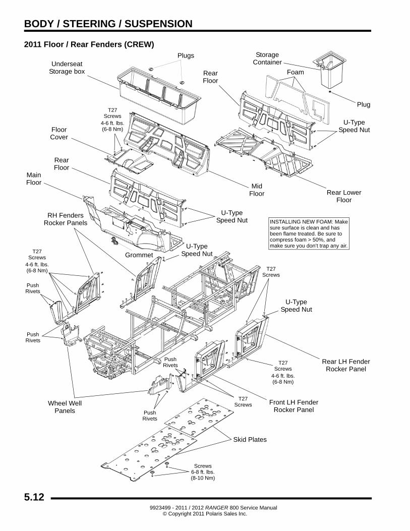
2011 Floor / Rear Fenders (CREW)
Skid Plates
FloorCover
MainFloor
Foam
Wheel WellPanels
RearFloor
Rear LH FenderRocker Panel
StorageContainer
U-TypeSpeed NutT27
Screws4-6 ft. lbs.(6-8 Nm)
PushRivets
PushRivets
PushRivets
T27Screws
4-6 ft. lbs.(6-8 Nm)
T27Screws
4-6 ft. lbs.(6-8 Nm)
Screws6-8 ft. lbs.(8-10 Nm)
U-TypeSpeed Nut
T27Screws
PushRivets
UnderseatStorage box
Rear LowerFloor
Plug
U-TypeSpeed Nut
Plugs
RearFloor
Front LH FenderRocker Panel
T27Screws
RH FendersRocker Panels
MidFloor
U-TypeSpeed Nut
Grommet
INSTALLING NEW FOAM: Makesure surface is clean and hasbeen flame treated. Be sure tocompress foam > 50%, andmake sure you don’t trap any air.
5.129923499 - 2011 / 2012 RANGER 800 Service Manual
© Copyright 2011 Polaris Sales Inc.
BODY / STEERING / SUSPENSION
5
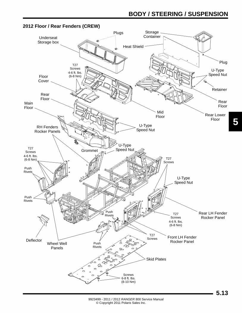
2012 Floor / Rear Fenders (CREW)
Skid Plates
FloorCover
MainFloor
Wheel WellPanels
RearFloor
Rear LH FenderRocker Panel
StorageContainer
U-TypeSpeed NutT27
Screws4-6 ft. lbs.(6-8 Nm)
PushRivets
PushRivets
PushRivets
T27Screws
4-6 ft. lbs.(6-8 Nm)
T27Screws
4-6 ft. lbs.(6-8 Nm)
Screws6-8 ft. lbs.(8-10 Nm)
U-TypeSpeed Nut
T27Screws
PushRivets
UnderseatStorage box
Rear LowerFloor
Plug
U-TypeSpeed Nut
Plugs
RearFloor
Front LH FenderRocker Panel
T27Screws
RH FendersRocker Panels
MidFloor
U-TypeSpeed Nut
Grommet
Heat Shield
Deflector
Retainer
5.139923499 - 2011 / 2012 RANGER 800 Service Manual
© Copyright 2011 Polaris Sales Inc.
BODY / STEERING / SUSPENSION
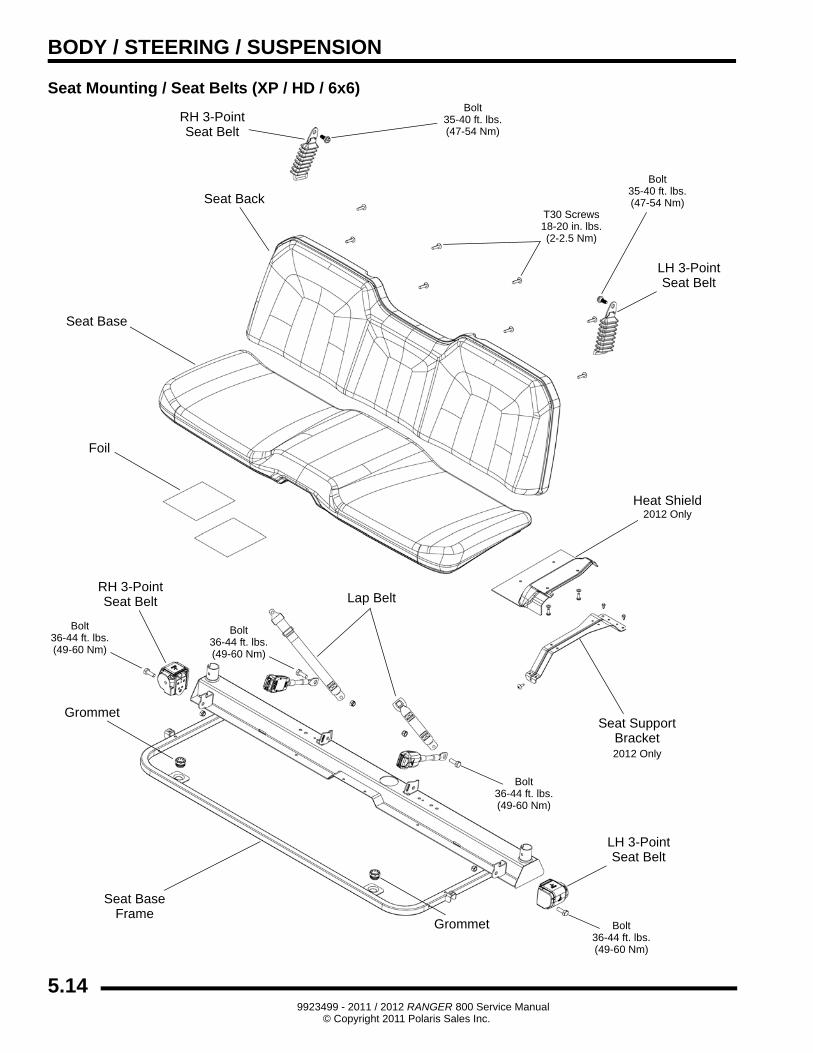
Seat Mounting / Seat Belts (XP / HD / 6x6)
Seat Base
Seat Back
Bolt
Foil
Seat BaseFrame
Grommet
Lap Belt
(49-60 Nm)36-44 ft. lbs.
T30 Screws
(2-2.5 Nm)18-20 in. lbs.
Grommet
LH 3-PointSeat Belt
LH 3-PointSeat Belt
RH 3-PointSeat Belt
RH 3-PointSeat Belt
Bolt
(47-54 Nm)35-40 ft. lbs.
Bolt
(47-54 Nm)35-40 ft. lbs.
Bolt
(49-60 Nm)36-44 ft. lbs.
Bolt
(49-60 Nm)36-44 ft. lbs.
Bolt
(49-60 Nm)36-44 ft. lbs.
Heat Shield
Seat SupportBracket
2012 Only
2012 Only
5.149923499 - 2011 / 2012 RANGER 800 Service Manual
© Copyright 2011 Polaris Sales Inc.
BODY / STEERING / SUSPENSION
5
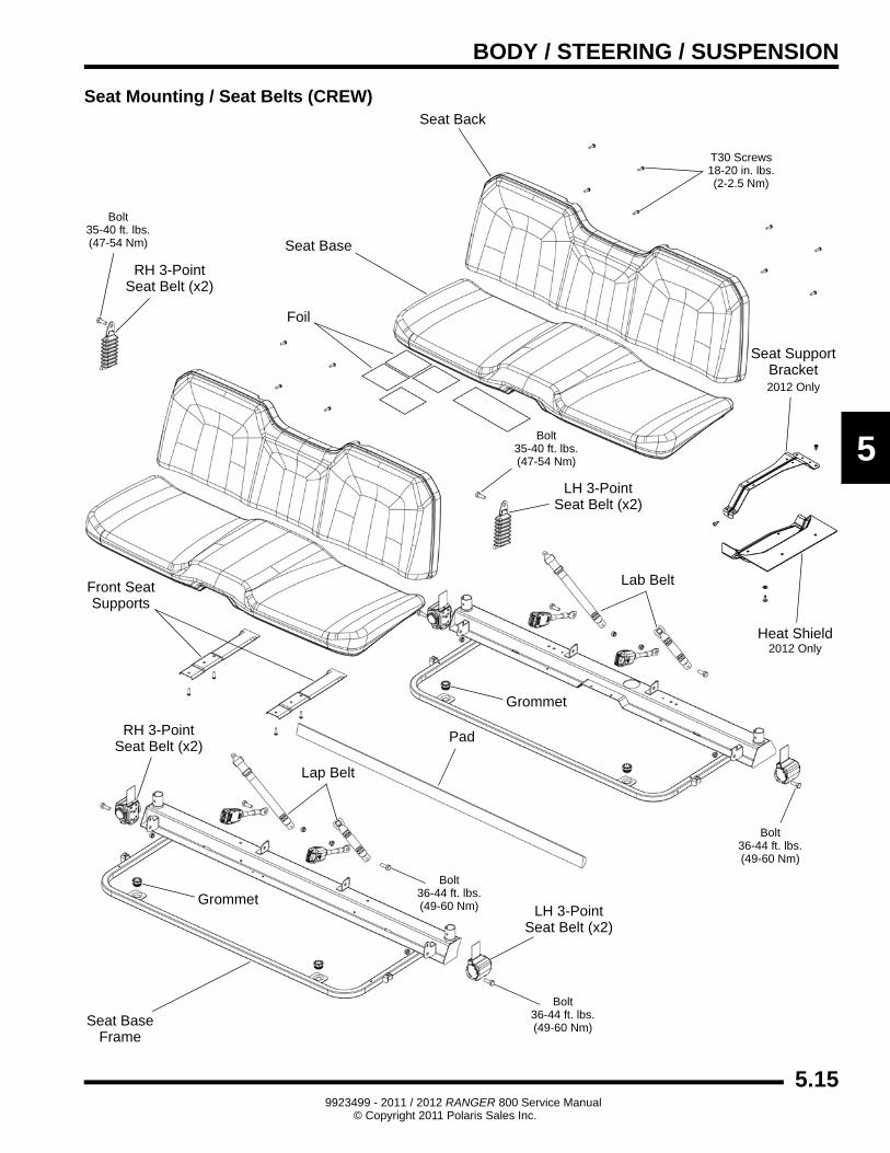
Seat Mounting / Seat Belts (CREW)
Seat Base
Seat Back
Foil
Seat BaseFrame
Lap Belt
T30 Screws
(2-2.5 Nm)18-20 in. lbs.
Grommet
LH 3-PointSeat Belt (x2)
LH 3-PointSeat Belt (x2)
RH 3-PointSeat Belt (x2)
RH 3-PointSeat Belt (x2)
Bolt
(47-54 Nm)35-40 ft. lbs.
Bolt
(49-60 Nm)36-44 ft. lbs.
Bolt
(49-60 Nm)36-44 ft. lbs.
Heat Shield
Seat SupportBracket
2012 Only
2012 Only
Bolt
(47-54 Nm)35-40 ft. lbs.
Grommet
Lab BeltFront SeatSupports
Pad
Bolt
(49-60 Nm)36-44 ft. lbs.
5.159923499 - 2011 / 2012 RANGER 800 Service Manual
© Copyright 2011 Polaris Sales Inc.
BODY / STEERING / SUSPENSION
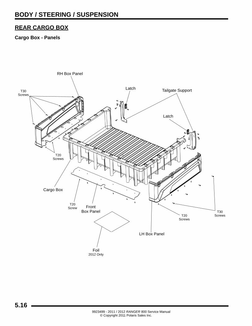
REAR CARGO BOX
Cargo Box - Panels
Tailgate Support
RH Box Panel
LH Box Panel
FrontBox Panel
Latch
Latch
Cargo Box
T30Screws
T20Screws
T20Screws
T20Screw
T30Screws
Foil2012 Only
5.169923499 - 2011 / 2012 RANGER 800 Service Manual
© Copyright 2011 Polaris Sales Inc.
BODY / STEERING / SUSPENSION
5
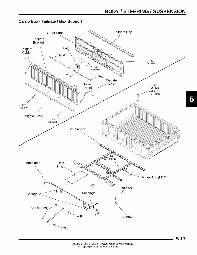
Cargo Box - Tailgate / Box Support
TailgateBracket
Tailgate Cap
LatchTailgateCable
Tailgate Tube
Inner
Rod
Outer Panel
Box Support
Box Latch
Shock Pins
Heat
Clip
Hinge Bolt (M10)
Shield
TailgateCable
Rod
Panel
Springs
Clip
Bushings
Screw
Bumper
T27Screws
4-6 ft. lbs.(6-8 Nm)
T20Screws
T30Screws
T30Screws
T27Screw
Nut(M10)
5.179923499 - 2011 / 2012 RANGER 800 Service Manual
© Copyright 2011 Polaris Sales Inc.
BODY / STEERING / SUSPENSION
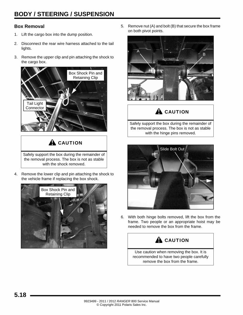
Box Removal
1. Lift the cargo box into the dump position.
2. Disconnect the rear wire harness attached to the tail lights.
3. Remove the upper clip and pin attaching the shock to the cargo box.
4. Remove the lower clip and pin attaching the shock to the vehicle frame if replacing the box shock.
5. Remove nut (A) and bolt (B) that secure the box frame on both pivot points.
6. With both hinge bolts removed, lift the box from the frame. Two people or an appropriate hoist may be needed to remove the box from the frame.
CAUTION
Safely support the box during the remainder of the removal process. The box is not as stable
with the shock removed.
Tail LightConnector
Box Shock Pin andRetaining Clip
Box Shock Pin andRetaining Clip
CAUTION
Safely support the box during the remainder of the removal process. The box is not as stable
with the hinge pins removed.
CAUTION
Use caution when removing the box. It is recommended to have two people carefully
remove the box from the frame.
AB
Slide Bolt Out
5.189923499 - 2011 / 2012 RANGER 800 Service Manual
© Copyright 2011 Polaris Sales Inc.
BODY / STEERING / SUSPENSION
5
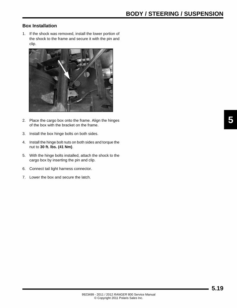
Box Installation
1. If the shock was removed, install the lower portion of the shock to the frame and secure it with the pin and clip.
2. Place the cargo box onto the frame. Align the hinges of the box with the bracket on the frame.
3. Install the box hinge bolts on both sides.
4. Install the hinge bolt nuts on both sides and torque the nut to 30 ft. lbs. (41 Nm).
5. With the hinge bolts installed, attach the shock to the cargo box by inserting the pin and clip.
6. Connect tail light harness connector.
7. Lower the box and secure the latch.
LowerShock Pin
5.199923499 - 2011 / 2012 RANGER 800 Service Manual
© Copyright 2011 Polaris Sales Inc.
BODY / STEERING / SUSPENSION
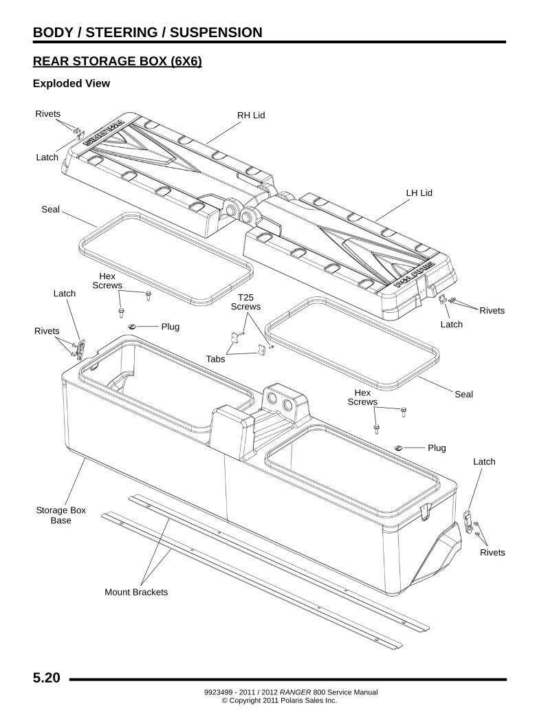
REAR STORAGE BOX (6X6)
Exploded View
RH Lid
Mount Brackets
Seal
Storage BoxBase
Latch
Plug
T25Screws
Plug
LH Lid
Tabs
Seal
Latch
Latch
Latch
HexScrews
HexScrews
Rivets
Rivets
Rivets
Rivets
5.209923499 - 2011 / 2012 RANGER 800 Service Manual
© Copyright 2011 Polaris Sales Inc.
BODY / STEERING / SUSPENSION
5
BODY COMPONENT REMOVAL
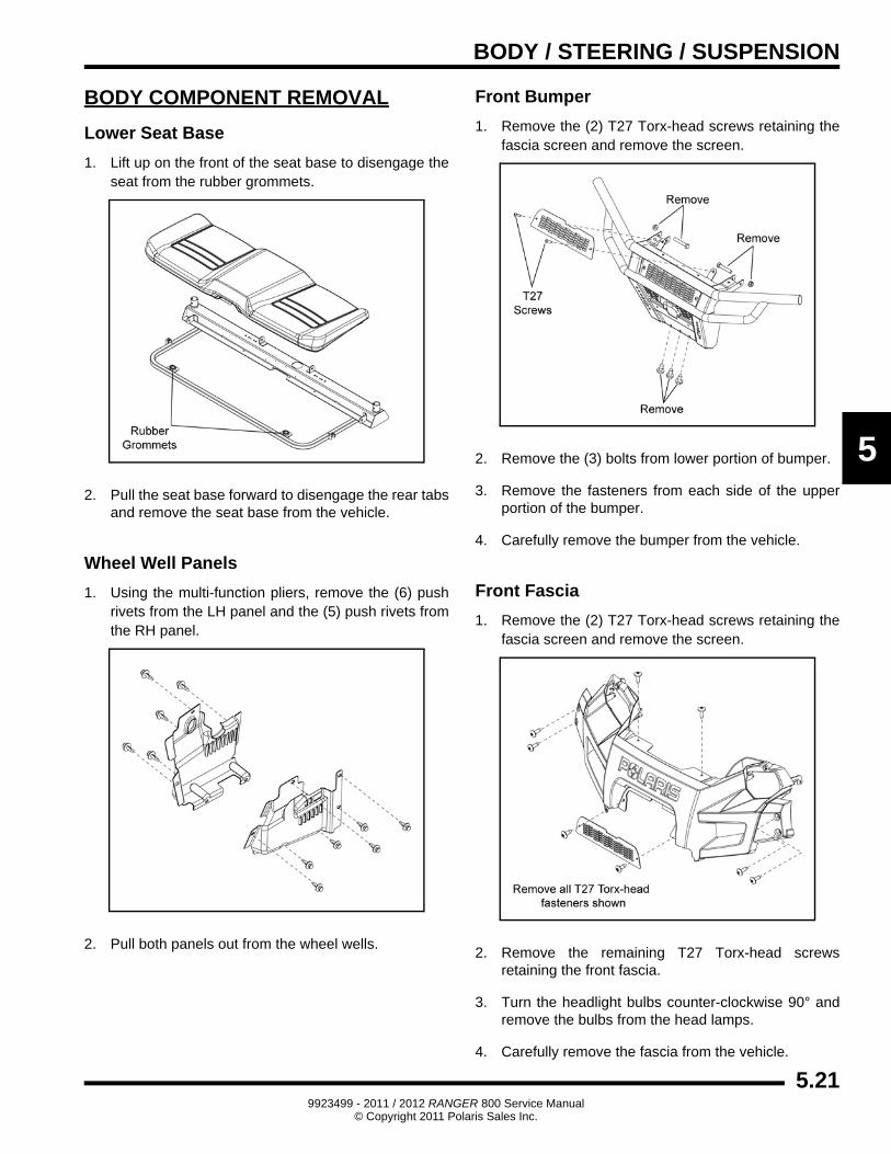
Lower Seat Base
1. Lift up on the front of the seat base to disengage the seat from the rubber grommets.
2. Pull the seat base forward to disengage the rear tabs and remove the seat base from the vehicle.
Wheel Well Panels
1. Using the multi-function pliers, remove the (6) push rivets from the LH panel and the (5) push rivets from the RH panel.
2. Pull both panels out from the wheel wells.
Front Bumper
1. Remove the (2) T27 Torx-head screws retaining the fascia screen and remove the screen.
2. Remove the (3) bolts from lower portion of bumper.
3. Remove the fasteners from each side of the upper portion of the bumper.
4. Carefully remove the bumper from the vehicle.
Front Fascia
1. Remove the (2) T27 Torx-head screws retaining the fascia screen and remove the screen.
2. Remove the remaining T27 Torx-head screws retaining the front fascia.
3. Turn the headlight bulbs counter-clockwise 90° and remove the bulbs from the head lamps.
4. Carefully remove the fascia from the vehicle.
5.219923499 - 2011 / 2012 RANGER 800 Service Manual
© Copyright 2011 Polaris Sales Inc.
BODY / STEERING / SUSPENSION
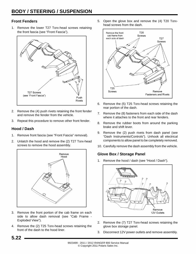
Front Fenders
1. Remove the lower T27 Torx-head screws retaining the front fascia (see “Front Fascia”).
2. Remove the (4) push rivets retaining the front fender and remove the fender from the vehicle.
3. Repeat this procedure to remove other front fender.
Hood / Dash
1. Remove front fascia (see “Front Fascia” removal).
2. Unlatch the hood and remove the (2) T27 Torx-head screws to remove the hood assembly.
3. Remove the front portion of the cab frame on each side to allow dash removal (see “Cab Frame - Exploded View”).
4. Remove the (2) T25 Torx-head screws retaining the front of the dash to the hood liner.
5. Open the glove box and remove the (4) T20 Torx-head screws from the dash.
6. Remove the (5) T25 Torx-head screws retaining the rear portion of the dash.
7. Remove the (8) fasteners from each side of the dash where it attaches to the front and rear fenders.
8. Remove the rubber boots from around the parking brake and shift lever.
9. Remove the (2) push rivets from dash panel (see “Dash Instruments/Controls”). Unhook all electrical components to allow panel to be completely removed.
10. Carefully remove the dash assembly from the vehicle.
Glove Box / Storage Panel
1. Remove the hood / dash (see “Hood / Dash”).
2. Remove the (7) T27 Torx-head screws retaining the glove box storage panel.
3. Disconnect 12V power outlets and remove assembly.
5.229923499 - 2011 / 2012 RANGER 800 Service Manual
© Copyright 2011 Polaris Sales Inc.
BODY / STEERING / SUSPENSION
5
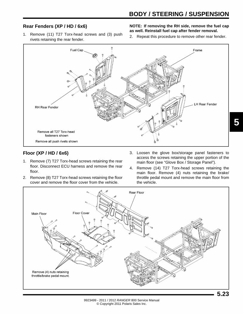
Rear Fenders (XP / HD / 6x6)
1. Remove (11) T27 Torx-head screws and (3) push rivets retaining the rear fender.
NOTE: If removing the RH side, remove the fuel cap as well. Reinstall fuel cap after fender removal.
2. Repeat this procedure to remove other rear fender.
Floor (XP / HD / 6x6)
1. Remove (7) T27 Torx-head screws retaining the rear floor. Disconnect ECU harness and remove the rear floor.
2. Remove (8) T27 Torx-head screws retaining the floor cover and remove the floor cover from the vehicle.
3. Loosen the glove box/storage panel fasteners to access the screws retaining the upper portion of the main floor (see “Glove Box / Storage Panel”).
4. Remove (14) T27 Torx-head screws retaining the main floor. Remove (4) nuts retaining the brake/throttle pedal mount and remove the main floor from the vehicle.
5.239923499 - 2011 / 2012 RANGER 800 Service Manual
© Copyright 2011 Polaris Sales Inc.
BODY / STEERING / SUSPENSION
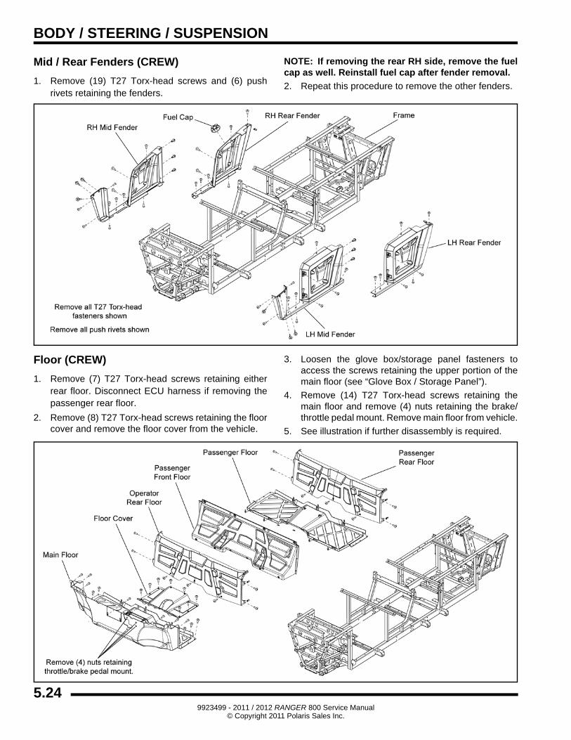
Mid / Rear Fenders (CREW)
1. Remove (19) T27 Torx-head screws and (6) push rivets retaining the fenders.
NOTE: If removing the rear RH side, remove the fuel cap as well. Reinstall fuel cap after fender removal.
2. Repeat this procedure to remove the other fenders.
Floor (CREW)
1. Remove (7) T27 Torx-head screws retaining either rear floor. Disconnect ECU harness if removing the passenger rear floor.
2. Remove (8) T27 Torx-head screws retaining the floor cover and remove the floor cover from the vehicle.
3. Loosen the glove box/storage panel fasteners to access the screws retaining the upper portion of the main floor (see “Glove Box / Storage Panel”).
4. Remove (14) T27 Torx-head screws retaining the main floor and remove (4) nuts retaining the brake/throttle pedal mount. Remove main floor from vehicle.
5. See illustration if further disassembly is required.
5.249923499 - 2011 / 2012 RANGER 800 Service Manual
© Copyright 2011 Polaris Sales Inc.
BODY / STEERING / SUSPENSION
5
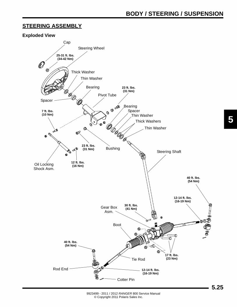
STEERING ASSEMBLY
Exploded View
Boot
Rod End
Steering Wheel
Cap
Pivot Tube
Steering Shaft
Cotter Pin
Gear Box
Oil LockingShock Asm.
Asm.
17 ft. lbs.(23 Nm)
40 ft. lbs.(54 Nm)
12-14 ft. lbs.(16-19 Nm)
30 ft. lbs.(41 Nm)
25-31 ft. lbs.(34-42 Nm)
23 ft. lbs.(31 Nm)
23 ft. lbs.(31 Nm)
7 ft. lbs.(10 Nm)
12 ft. lbs.(16 Nm)
Tie Rod
12-14 ft. lbs.(16-19 Nm)
40 ft. lbs.(54 Nm)
Thick Washer
Thin Washer
Spacer
Bearing
BearingSpacer
Thin Washer
Thick Washers
Thin Washer
Bushing
5.259923499 - 2011 / 2012 RANGER 800 Service Manual
© Copyright 2011 Polaris Sales Inc.
BODY / STEERING / SUSPENSION
Steering Wheel Removal (Non-EPS Models)
1. Remove the steering wheel cap.
2. Loosen the nut and back it half way off the steering shaft.
3. With a glove on your hand, place it under the steering wheel. Lift upward on the inner portion of the steering wheel while using a hammer to strike the steering shaft nut.
IMPORTANT: If the steering wheel will not pop loose, proceed to “Steering Shaft Removal”.
4. Once the steering wheel pops loose, completely remove the nut and lift the steering wheel off the shaft.
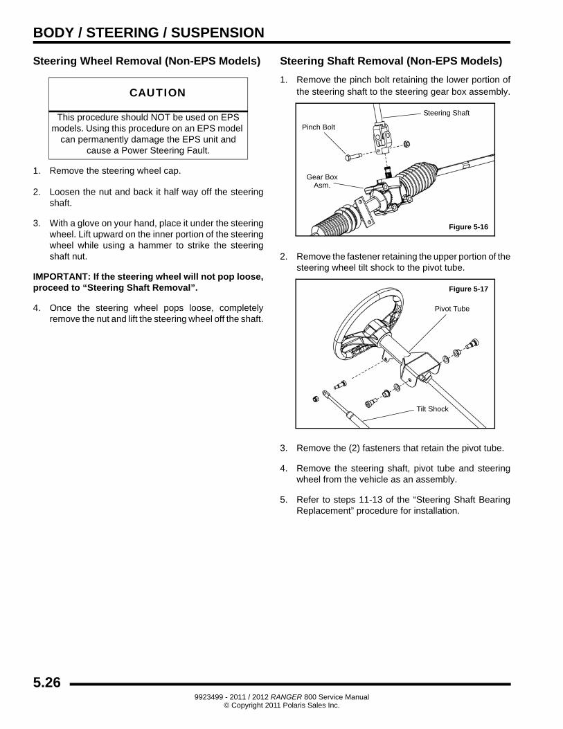
Steering Shaft Removal (Non-EPS Models)
1. Remove the pinch bolt retaining the lower portion of the steering shaft to the steering gear box assembly.
2. Remove the fastener retaining the upper portion of the steering wheel tilt shock to the pivot tube.
3. Remove the (2) fasteners that retain the pivot tube.
4. Remove the steering shaft, pivot tube and steering wheel from the vehicle as an assembly.
5. Refer to steps 11-13 of the “Steering Shaft Bearing Replacement” procedure for installation.
CAUTION
This procedure should NOT be used on EPS models. Using this procedure on an EPS model
can permanently damage the EPS unit and cause a Power Steering Fault.
Figure 5-16
Pinch Bolt
Gear BoxAsm.
Steering Shaft
Figure 5-17
Pivot Tube
Tilt Shock
5.269923499 - 2011 / 2012 RANGER 800 Service Manual
© Copyright 2011 Polaris Sales Inc.
BODY / STEERING / SUSPENSION
5
Steering Shaft Bearing Replacement
IMPORTANT: Replacement pivot tube assembly comes with new upper and lower bearings installed. Use this procedure if replacing just the bearings only.
1. Perform the “Steering Shaft Removal” procedure.
2. Remove the steering wheel cap and retaining nut.
3. Press steering shaft out of the steering wheel and pivot tube.
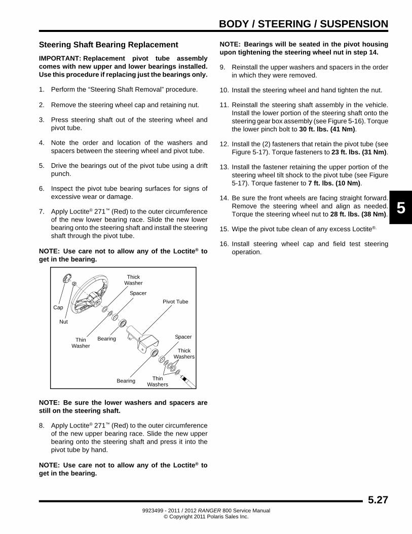
4. Note the order and location of the washers and spacers between the steering wheel and pivot tube.
5. Drive the bearings out of the pivot tube using a drift punch.
6. Inspect the pivot tube bearing surfaces for signs of excessive wear or damage.
7. Apply Loctite® 271™ (Red) to the outer circumference of the new lower bearing race. Slide the new lower bearing onto the steering shaft and install the steering shaft through the pivot tube.
NOTE: Use care not to allow any of the Loctite® to get in the bearing.
NOTE: Be sure the lower washers and spacers are still on the steering shaft.
8. Apply Loctite® 271™ (Red) to the outer circumference of the new upper bearing race. Slide the new upper bearing onto the steering shaft and press it into the pivot tube by hand.
NOTE: Use care not to allow any of the Loctite® to get in the bearing.
NOTE: Bearings will be seated in the pivot housing upon tightening the steering wheel nut in step 14.
9. Reinstall the upper washers and spacers in the order in which they were removed.
10. Install the steering wheel and hand tighten the nut.
11. Reinstall the steering shaft assembly in the vehicle. Install the lower portion of the steering shaft onto the steering gear box assembly (see Figure 5-16). Torque the lower pinch bolt to 30 ft. lbs. (41 Nm).
12. Install the (2) fasteners that retain the pivot tube (see Figure 5-17). Torque fasteners to 23 ft. lbs. (31 Nm).
13. Install the fastener retaining the upper portion of the steering wheel tilt shock to the pivot tube (see Figure 5-17). Torque fastener to 7 ft. lbs. (10 Nm).
14. Be sure the front wheels are facing straight forward. Remove the steering wheel and align as needed. Torque the steering wheel nut to 28 ft. lbs. (38 Nm).
15. Wipe the pivot tube clean of any excess Loctite®.
16. Install steering wheel cap and field test steering operation.
Spacer
ThinWasher
ThickWasher
Bearing
Cap
Nut
Pivot Tube
Bearing
Spacer
ThinWashers
ThickWashers
5.279923499 - 2011 / 2012 RANGER 800 Service Manual
© Copyright 2011 Polaris Sales Inc.
BODY / STEERING / SUSPENSION
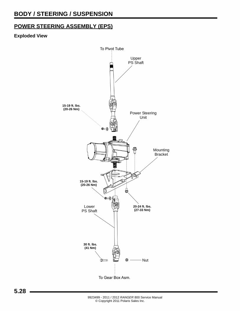
POWER STEERING ASSEMBLY (EPS)
Exploded View
Power SteeringUnit
Nut
30 ft. lbs.(41 Nm)
UpperPS Shaft
LowerPS Shaft
15-19 ft. lbs.(20-26 Nm)
15-19 ft. lbs.(20-26 Nm)
MountingBracket
20-24 ft. lbs.(27-33 Nm)
5.289923499 - 2011 / 2012 RANGER 800 Service Manual
© Copyright 2011 Polaris Sales Inc.
BODY / STEERING / SUSPENSION
5
Steering Wheel Removal (EPS Models)
1. Remove the upper steering shaft, pivot tube and steering wheel as an assembly before attempting to remove the steering wheel. Refer to “Power Steering Unit Removal (EPS Models)”.
2. Remove the steering wheel cap.
3. Loosen the nut and back it half way off the steering shaft.
4. Place the assembly in a vise.
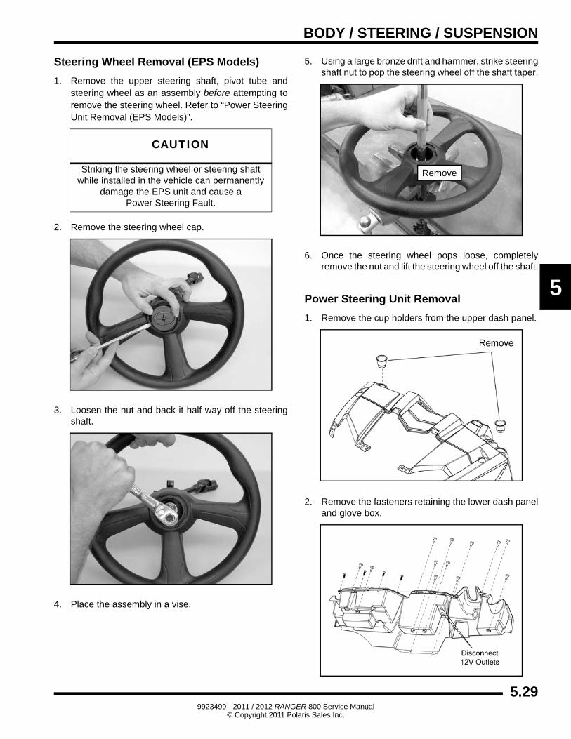
5. Using a large bronze drift and hammer, strike steering shaft nut to pop the steering wheel off the shaft taper.
6. Once the steering wheel pops loose, completely remove the nut and lift the steering wheel off the shaft.
Power Steering Unit Removal
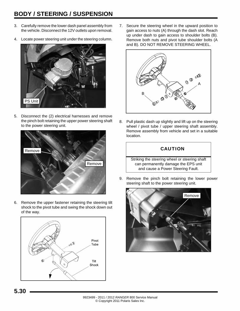
1. Remove the cup holders from the upper dash panel.
2. Remove the fasteners retaining the lower dash panel and glove box.
CAUTION
Striking the steering wheel or steering shaftwhile installed in the vehicle can permanently
damage the EPS unit and cause aPower Steering Fault.
Remove
5.299923499 - 2011 / 2012 RANGER 800 Service Manual
© Copyright 2011 Polaris Sales Inc.
BODY / STEERING / SUSPENSION
3. Carefully remove the lower dash panel assembly from the vehicle. Disconnect the 12V outlets upon removal.
4. Locate power steering unit under the steering column.
5. Disconnect the (2) electrical harnesses and remove the pinch bolt retaining the upper power steering shaft to the power steering unit.
6. Remove the upper fastener retaining the steering tilt shock to the pivot tube and swing the shock down out of the way.
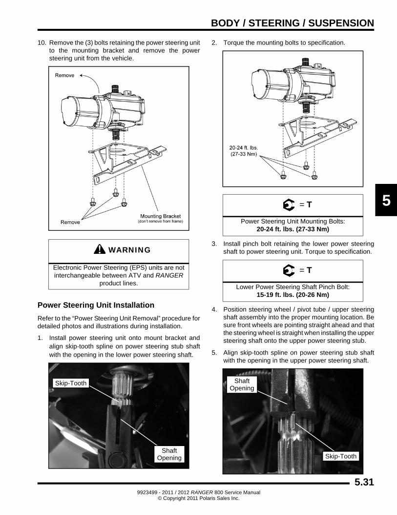
7. Secure the steering wheel in the upward position to gain access to nuts (A) through the dash slot. Reach up under dash to gain access to shoulder bolts (B). Remove both nuts and pivot tube shoulder bolts (A and B). DO NOT REMOVE STEERING WHEEL.
8. Pull plastic dash up slightly and lift up on the steering wheel / pivot tube / upper steering shaft assembly. Remove assembly from vehicle and set in a suitable location.
9. Remove the pinch bolt retaining the lower power steering shaft to the power steering unit.
PS Unit
Remove
Remove
CAUTION
Striking the steering wheel or steering shaftcan permanently damage the EPS unit
and cause a Power Steering Fault.
A
B
Remove
5.309923499 - 2011 / 2012 RANGER 800 Service Manual
© Copyright 2011 Polaris Sales Inc.
BODY / STEERING / SUSPENSION
5
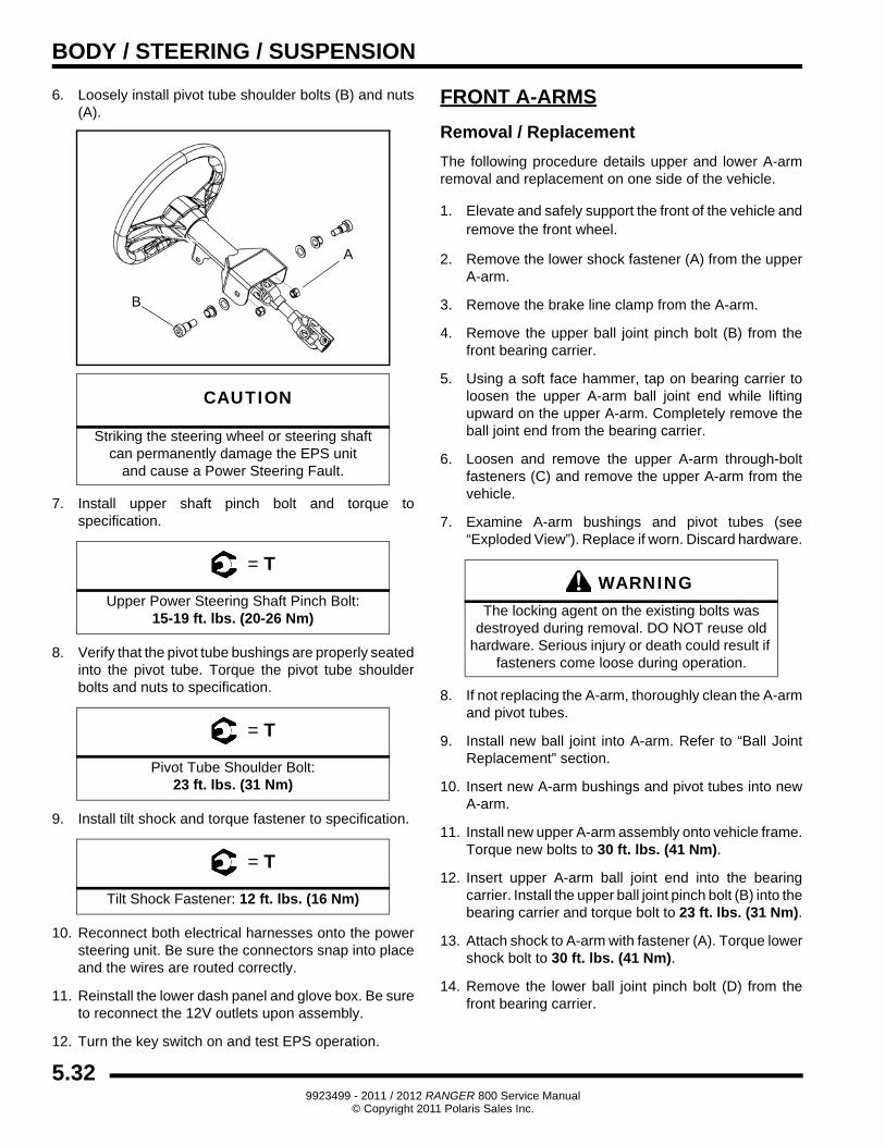
10. Remove the (3) bolts retaining the power steering unit to the mounting bracket and remove the power steering unit from the vehicle.
Power Steering Unit Installation
Refer to the “Power Steering Unit Removal” procedure for detailed photos and illustrations during installation.
1. Install power steering unit onto mount bracket and align skip-tooth spline on power steering stub shaft with the opening in the lower power steering shaft.
2. Torque the mounting bolts to specification.
3. Install pinch bolt retaining the lower power steering shaft to power steering unit. Torque to specification.
4. Position steering wheel / pivot tube / upper steering shaft assembly into the proper mounting location. Be sure front wheels are pointing straight ahead and that the steering wheel is straight when installing the upper steering shaft onto the upper power steering stub.
5. Align skip-tooth spline on power steering stub shaft with the opening in the upper power steering shaft.
WARNING
Electronic Power Steering (EPS) units are not interchangeable between ATV and RANGER
product lines.
Skip-Tooth
ShaftOpening
= T
Power Steering Unit Mounting Bolts:20-24 ft. lbs. (27-33 Nm)
= T
Lower Power Steering Shaft Pinch Bolt:15-19 ft. lbs. (20-26 Nm)
Skip-Tooth
ShaftOpening
5.319923499 - 2011 / 2012 RANGER 800 Service Manual
© Copyright 2011 Polaris Sales Inc.
BODY / STEERING / SUSPENSION
6. Loosely install pivot tube shoulder bolts (B) and nuts (A).
7. Install upper shaft pinch bolt and torque to specification.
8. Verify that the pivot tube bushings are properly seated into the pivot tube. Torque the pivot tube shoulder bolts and nuts to specification.
9. Install tilt shock and torque fastener to specification.
10. Reconnect both electrical harnesses onto the power steering unit. Be sure the connectors snap into place and the wires are routed correctly.
11. Reinstall the lower dash panel and glove box. Be sure to reconnect the 12V outlets upon assembly.
12. Turn the key switch on and test EPS operation.
FRONT A-ARMS
Removal / Replacement
The following procedure details upper and lower A-arm removal and replacement on one side of the vehicle.
1. Elevate and safely support the front of the vehicle and remove the front wheel.
2. Remove the lower shock fastener (A) from the upper A-arm.
3. Remove the brake line clamp from the A-arm.
4. Remove the upper ball joint pinch bolt (B) from the front bearing carrier.
5. Using a soft face hammer, tap on bearing carrier to loosen the upper A-arm ball joint end while lifting upward on the upper A-arm. Completely remove the ball joint end from the bearing carrier.
6. Loosen and remove the upper A-arm through-bolt fasteners (C) and remove the upper A-arm from the vehicle.
7. Examine A-arm bushings and pivot tubes (see “Exploded View”). Replace if worn. Discard hardware.
8. If not replacing the A-arm, thoroughly clean the A-arm and pivot tubes.
9. Install new ball joint into A-arm. Refer to “Ball Joint Replacement” section.
10. Insert new A-arm bushings and pivot tubes into new A-arm.
11. Install new upper A-arm assembly onto vehicle frame. Torque new bolts to 30 ft. lbs. (41 Nm).
12. Insert upper A-arm ball joint end into the bearing carrier. Install the upper ball joint pinch bolt (B) into the bearing carrier and torque bolt to 23 ft. lbs. (31 Nm).
13. Attach shock to A-arm with fastener (A). Torque lower shock bolt to 30 ft. lbs. (41 Nm).
14. Remove the lower ball joint pinch bolt (D) from the front bearing carrier.
CAUTION
Striking the steering wheel or steering shaftcan permanently damage the EPS unit
and cause a Power Steering Fault.
= T
Upper Power Steering Shaft Pinch Bolt:15-19 ft. lbs. (20-26 Nm)
= T
Pivot Tube Shoulder Bolt:23 ft. lbs. (31 Nm)
= T
Tilt Shock Fastener: 12 ft. lbs. (16 Nm)
A
B
WARNINGThe locking agent on the existing bolts was
destroyed during removal. DO NOT reuse old hardware. Serious injury or death could result if
fasteners come loose during operation.
5.329923499 - 2011 / 2012 RANGER 800 Service Manual
© Copyright 2011 Polaris Sales Inc.
BODY / STEERING / SUSPENSION
5
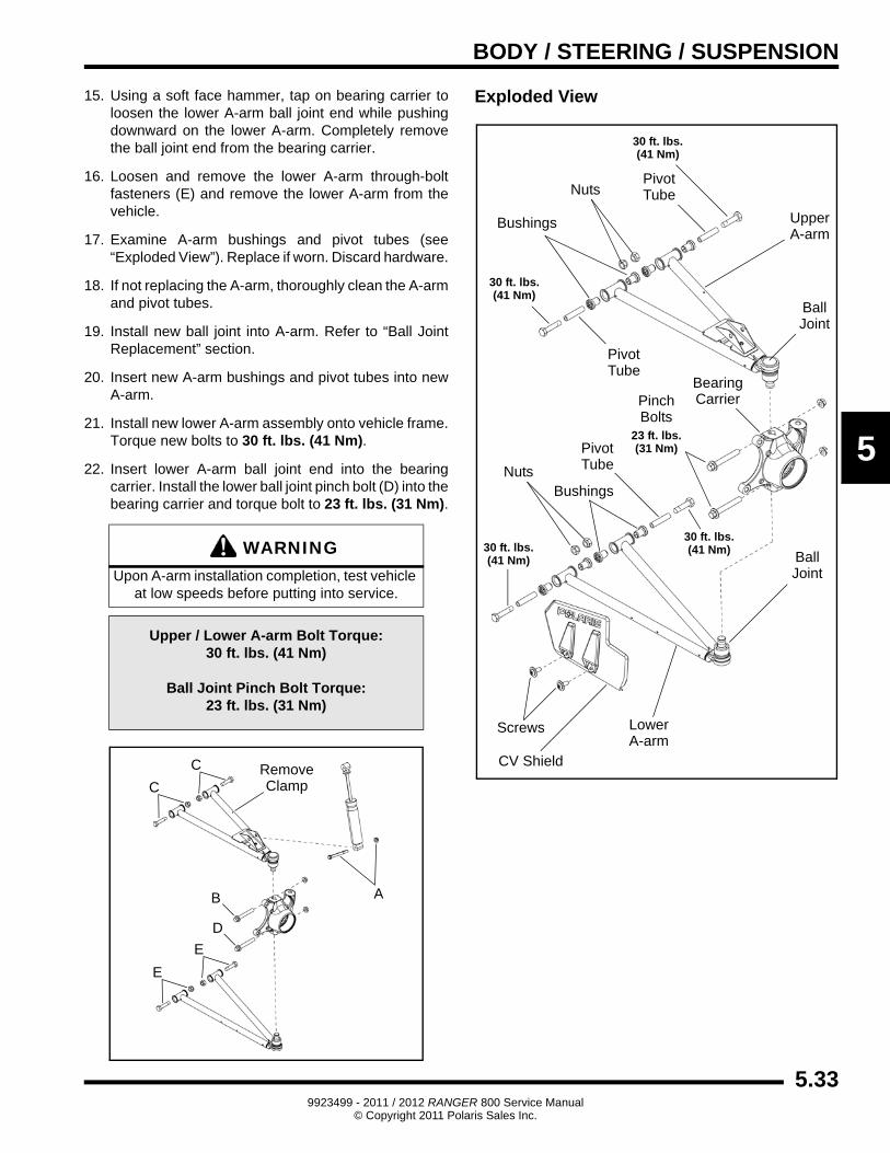
15. Using a soft face hammer, tap on bearing carrier to loosen the lower A-arm ball joint end while pushing downward on the lower A-arm. Completely remove the ball joint end from the bearing carrier.
16. Loosen and remove the lower A-arm through-bolt fasteners (E) and remove the lower A-arm from the vehicle.
17. Examine A-arm bushings and pivot tubes (see “Exploded View”). Replace if worn. Discard hardware.
18. If not replacing the A-arm, thoroughly clean the A-arm and pivot tubes.
19. Install new ball joint into A-arm. Refer to “Ball Joint Replacement” section.
20. Insert new A-arm bushings and pivot tubes into new A-arm.
21. Install new lower A-arm assembly onto vehicle frame. Torque new bolts to 30 ft. lbs. (41 Nm).
22. Insert lower A-arm ball joint end into the bearing carrier. Install the lower ball joint pinch bolt (D) into the bearing carrier and torque bolt to 23 ft. lbs. (31 Nm).
Exploded View
WARNINGUpon A-arm installation completion, test vehicle
at low speeds before putting into service.
Upper / Lower A-arm Bolt Torque:30 ft. lbs. (41 Nm)
Ball Joint Pinch Bolt Torque:23 ft. lbs. (31 Nm)
A
D
C
C
B
E
E
RemoveClamp
UpperA-arm
LowerA-arm
Screws
Ball
PinchBearing
CV Shield
Bushings
30 ft. lbs.(41 Nm)
Pivot
Ball
CarrierBolts
23 ft. lbs.(31 Nm)
30 ft. lbs.(41 Nm)
Joint
Tube
30 ft. lbs.(41 Nm)
PivotTube
Nuts
Joint
Bushings
PivotTubeNuts
30 ft. lbs.(41 Nm)
5.339923499 - 2011 / 2012 RANGER 800 Service Manual
© Copyright 2011 Polaris Sales Inc.
BODY / STEERING / SUSPENSION
BALL JOINT SERVICE
Removal
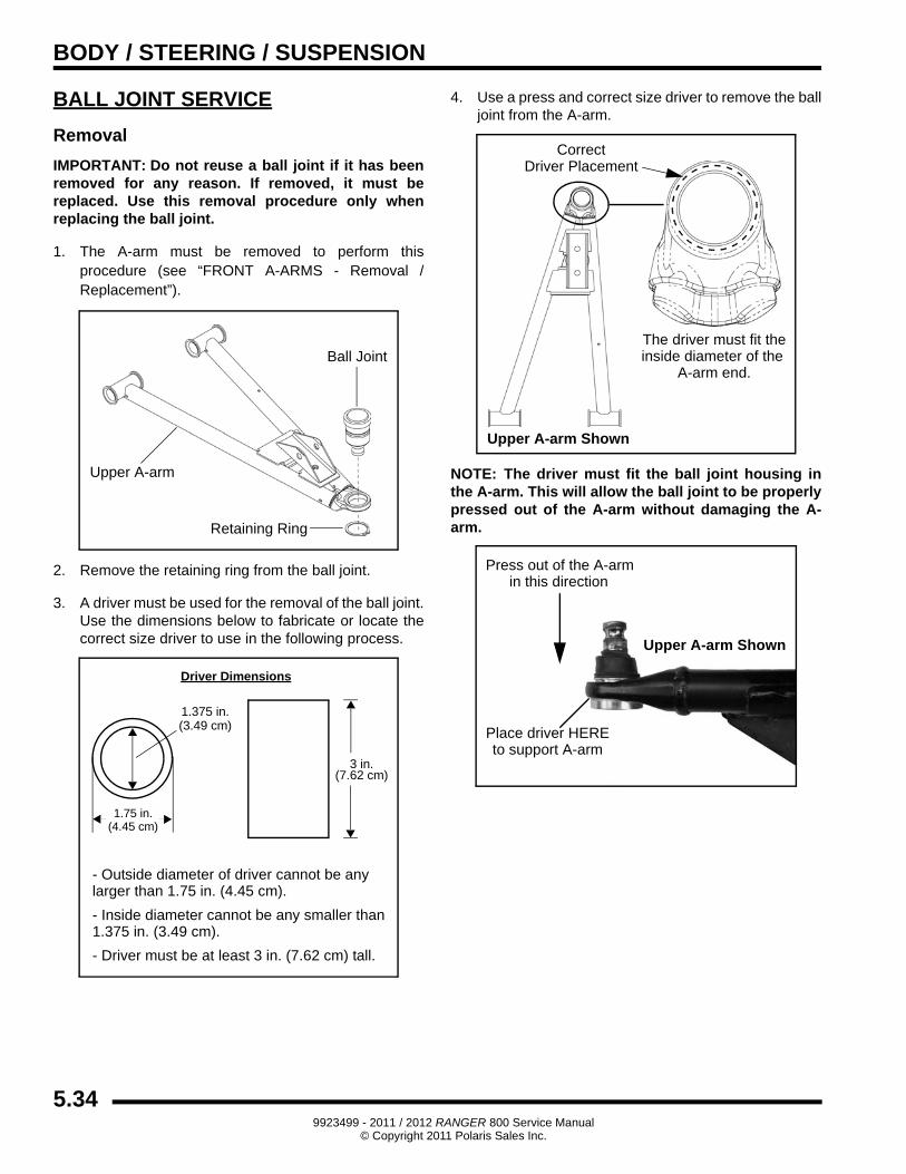
IMPORTANT: Do not reuse a ball joint if it has been removed for any reason. If removed, it must be replaced. Use this removal procedure only when replacing the ball joint.
1. The A-arm must be removed to perform this procedure (see “FRONT A-ARMS - Removal / Replacement”).
2. Remove the retaining ring from the ball joint.
3. A driver must be used for the removal of the ball joint. Use the dimensions below to fabricate or locate the correct size driver to use in the following process.
4. Use a press and correct size driver to remove the ball joint from the A-arm.
NOTE: The driver must fit the ball joint housing in the A-arm. This will allow the ball joint to be properly pressed out of the A-arm without damaging the A-arm.
Ball Joint
Upper A-arm
Retaining Ring
1.75 in.
1.375 in.(3.49 cm)
3 in.(7.62 cm)
Driver Dimensions
- Outside diameter of driver cannot be anylarger than 1.75 in. (4.45 cm).
- Inside diameter cannot be any smaller than1.375 in. (3.49 cm).
- Driver must be at least 3 in. (7.62 cm) tall.
(4.45 cm)
CorrectDriver Placement
The driver must fit theinside diameter of the
Upper A-arm Shown
A-arm end.
Press out of the A-armin this direction
Upper A-arm Shown
Place driver HEREto support A-arm
5.349923499 - 2011 / 2012 RANGER 800 Service Manual
© Copyright 2011 Polaris Sales Inc.
BODY / STEERING / SUSPENSION
5
Installation
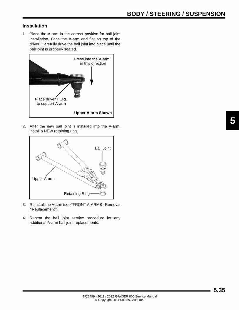
1. Place the A-arm in the correct position for ball joint installation. Face the A-arm end flat on top of the driver. Carefully drive the ball joint into place until the ball joint is properly seated.
2. After the new ball joint is installed into the A-arm, install a NEW retaining ring.
3. Reinstall the A-arm (see “FRONT A-ARMS - Removal / Replacement”).
4. Repeat the ball joint service procedure for any additional A-arm ball joint replacements.
Press into the A-armin this direction
Upper A-arm Shown
Place driver HEREto support A-arm
Ball Joint
Upper A-arm
Retaining Ring
5.359923499 - 2011 / 2012 RANGER 800 Service Manual
© Copyright 2011 Polaris Sales Inc.
BODY / STEERING / SUSPENSION
MID / REAR A-ARMS
Removal / Replacement
The following procedure details upper and lower A-arm removal and replacement on one side of the vehicle. Repeat the following steps to remove the A-arm(s) from the opposite side.
NOTE: Use the exploded view in this section as a reference during the procedure.
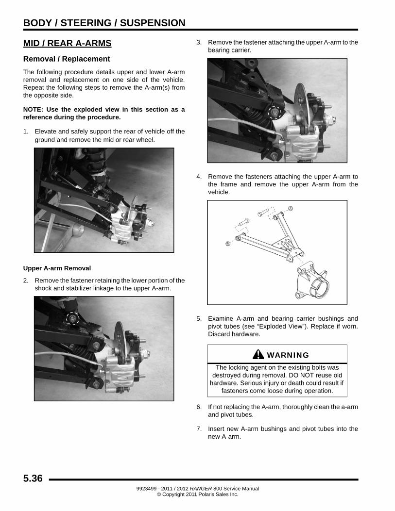
1. Elevate and safely support the rear of vehicle off the ground and remove the mid or rear wheel.
Upper A-arm Removal
2. Remove the fastener retaining the lower portion of the shock and stabilizer linkage to the upper A-arm.
3. Remove the fastener attaching the upper A-arm to the bearing carrier.
4. Remove the fasteners attaching the upper A-arm to the frame and remove the upper A-arm from the vehicle.
5. Examine A-arm and bearing carrier bushings and pivot tubes (see “Exploded View”). Replace if worn. Discard hardware.
6. If not replacing the A-arm, thoroughly clean the a-arm and pivot tubes.
7. Insert new A-arm bushings and pivot tubes into the new A-arm.
WARNINGThe locking agent on the existing bolts was
destroyed during removal. DO NOT reuse old hardware. Serious injury or death could result if
fasteners come loose during operation.
5.369923499 - 2011 / 2012 RANGER 800 Service Manual
© Copyright 2011 Polaris Sales Inc.
BODY / STEERING / SUSPENSION
5
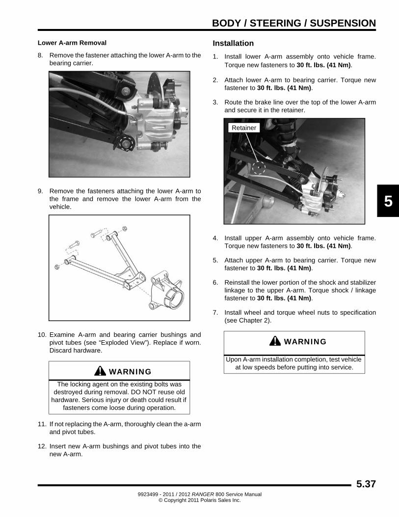
Lower A-arm Removal
8. Remove the fastener attaching the lower A-arm to the bearing carrier.
9. Remove the fasteners attaching the lower A-arm to the frame and remove the lower A-arm from the vehicle.
10. Examine A-arm and bearing carrier bushings and pivot tubes (see “Exploded View”). Replace if worn. Discard hardware.
11. If not replacing the A-arm, thoroughly clean the a-arm and pivot tubes.
12. Insert new A-arm bushings and pivot tubes into the new A-arm.
Installation
1. Install lower A-arm assembly onto vehicle frame. Torque new fasteners to 30 ft. lbs. (41 Nm).
2. Attach lower A-arm to bearing carrier. Torque new fastener to 30 ft. lbs. (41 Nm).
3. Route the brake line over the top of the lower A-arm and secure it in the retainer.
4. Install upper A-arm assembly onto vehicle frame. Torque new fasteners to 30 ft. lbs. (41 Nm).
5. Attach upper A-arm to bearing carrier. Torque new fastener to 30 ft. lbs. (41 Nm).
6. Reinstall the lower portion of the shock and stabilizer linkage to the upper A-arm. Torque shock / linkage fastener to 30 ft. lbs. (41 Nm).
7. Install wheel and torque wheel nuts to specification (see Chapter 2).
WARNINGThe locking agent on the existing bolts was
destroyed during removal. DO NOT reuse old hardware. Serious injury or death could result if
fasteners come loose during operation.
WARNING
Upon A-arm installation completion, test vehicle at low speeds before putting into service.
Retainer
5.379923499 - 2011 / 2012 RANGER 800 Service Manual
© Copyright 2011 Polaris Sales Inc.
BODY / STEERING / SUSPENSION
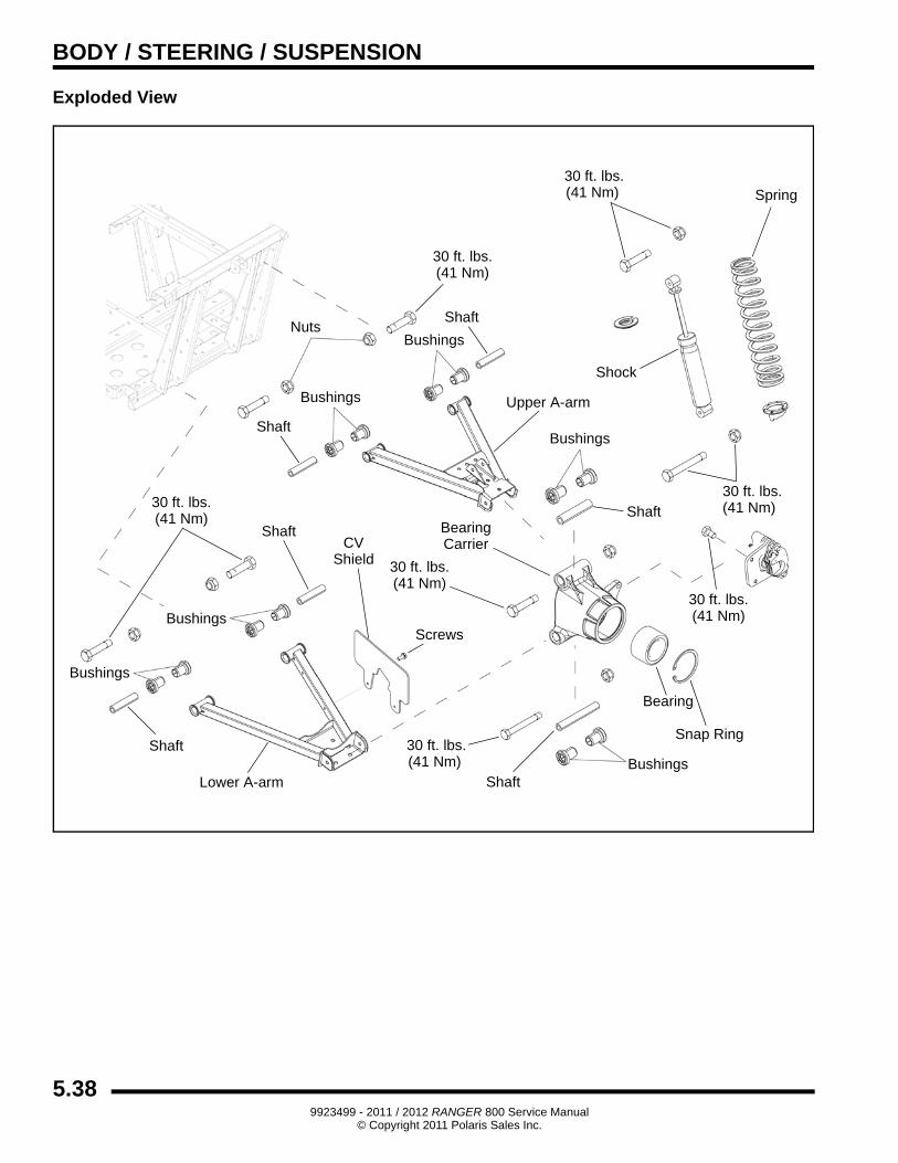
Exploded View
Screws
BearingCV Carrier
Shield
Shaft
Upper A-arm
Bushings
Spring
Snap Ring
Bushings
Lower A-arm
30 ft. lbs.
Shaft
Nuts
30 ft. lbs.(41 Nm)
30 ft. lbs.(41 Nm)
Shock
30 ft. lbs.(41 Nm)
30 ft. lbs.(41 Nm)
Bearing
Bushings
Shaft
Shaft
Bushings
30 ft. lbs.(41 Nm)
Shaft
(41 Nm)
Bushings
30 ft. lbs.(41 Nm)
Bushings
Shaft
5.389923499 - 2011 / 2012 RANGER 800 Service Manual
© Copyright 2011 Polaris Sales Inc.
BODY / STEERING / SUSPENSION
5
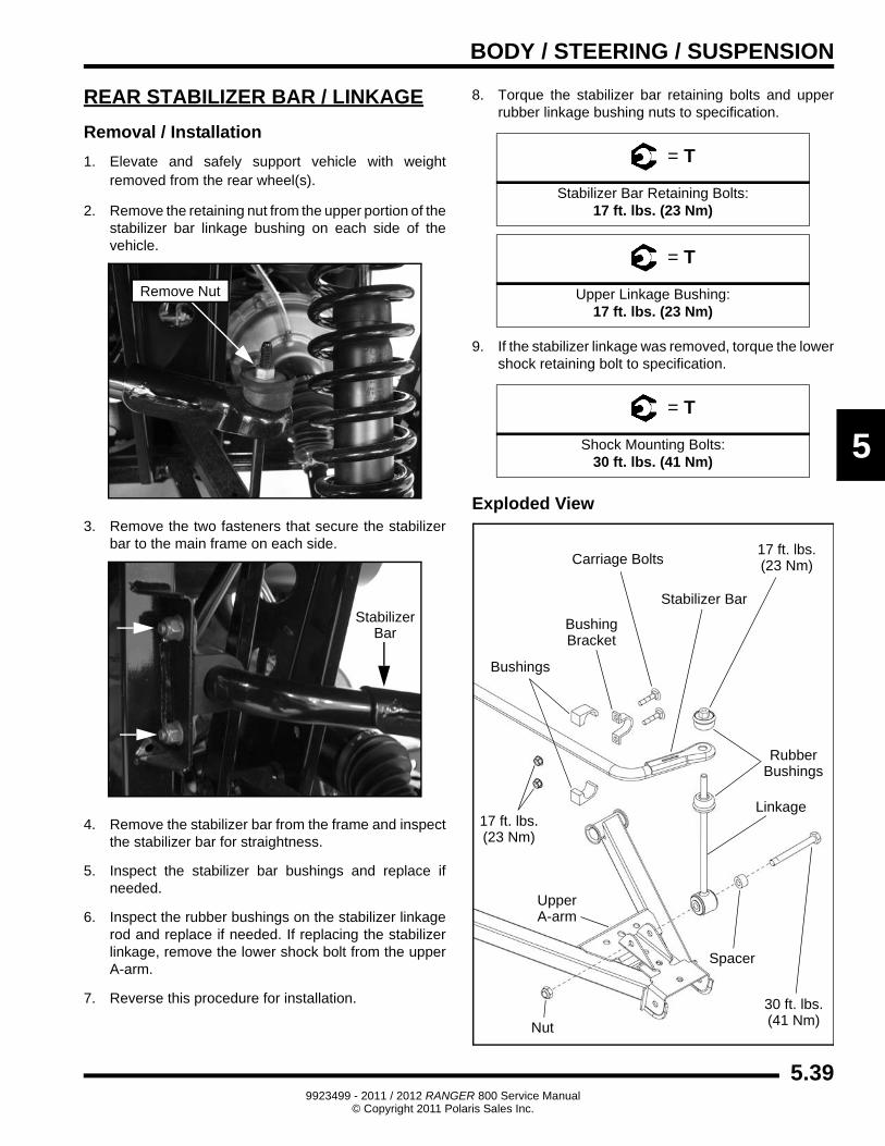
REAR STABILIZER BAR / LINKAGE
Removal / Installation
1. Elevate and safely support vehicle with weight removed from the rear wheel(s).
2. Remove the retaining nut from the upper portion of the stabilizer bar linkage bushing on each side of the vehicle.
3. Remove the two fasteners that secure the stabilizer bar to the main frame on each side.
4. Remove the stabilizer bar from the frame and inspect the stabilizer bar for straightness.
5. Inspect the stabilizer bar bushings and replace if needed.
6. Inspect the rubber bushings on the stabilizer linkage rod and replace if needed. If replacing the stabilizer linkage, remove the lower shock bolt from the upper A-arm.
7. Reverse this procedure for installation.
8. Torque the stabilizer bar retaining bolts and upper rubber linkage bushing nuts to specification.
9. If the stabilizer linkage was removed, torque the lower shock retaining bolt to specification.
Exploded View
Remove Nut
StabilizerBar
= T
Stabilizer Bar Retaining Bolts:17 ft. lbs. (23 Nm)
= T
Upper Linkage Bushing:17 ft. lbs. (23 Nm)
= T
Shock Mounting Bolts:30 ft. lbs. (41 Nm)
Bushings
Stabilizer Bar
BushingBracket
RubberBushings
UpperA-arm
17 ft. lbs.(23 Nm)
17 ft. lbs.(23 Nm)
Linkage
30 ft. lbs.(41 Nm)
Spacer
Nut
Carriage Bolts
5.399923499 - 2011 / 2012 RANGER 800 Service Manual
© Copyright 2011 Polaris Sales Inc.
BODY / STEERING / SUSPENSION
DECAL REPLACEMENT
The side panels, front and rear fender cabs are plastic polyethylene material. Therefore, they must be “flame treated” prior to installing a decal to ensure good adhesion. A bonus of the flame treating procedure is it can be used to reduce or eliminate the whitish stress marks that are sometimes left after a fender or cab is bent, flexed, or damaged.
To flame treat the decal area:
1. Pass the flame of a propane torch back and forth quickly over the area where the decal is to be applied until the surface appears slightly glossy. This should occur after just a few seconds of flame treating. Do not hold the torch too close to the surface (2-3 inches from the flame tip is recommended). Keep the torch moving to prevent damage.
2. Apply the decal on one edge first. Slowly lay down remainder of the decal while rubbing lightly over the decal surface to eliminate any air bubbles during the application.
WARNING
The following procedure involves the use of an open flame. Perform this procedure in a well ventilated area, away from gasoline or other flammable materials. Be sure the area to be flame treated is clean and free of gasoline
or flammable residue.
WARNING
Do not flame treat components that are installed on the vehicle. Remove the component from the
vehicle before flame treating.
CAUTION
Do not flame treat painted plastic components. Painted plastic surfaces should only be wiped
clean prior to decal adhesion.
5.409923499 - 2011 / 2012 RANGER 800 Service Manual
© Copyright 2011 Polaris Sales Inc.
BODY / STEERING / SUSPENSION
5
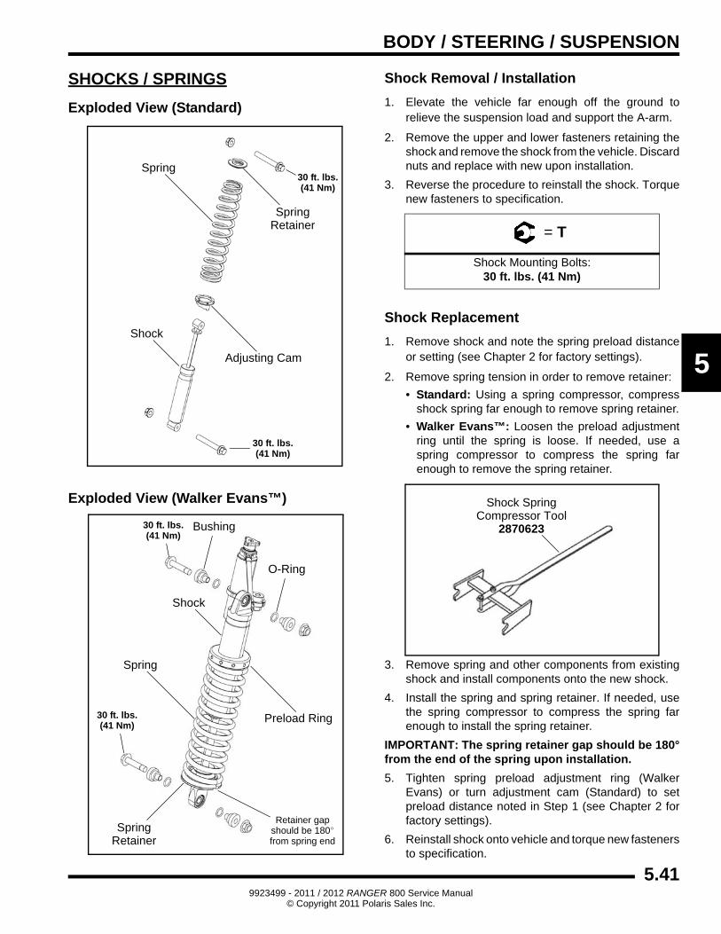
SHOCKS / SPRINGS
Exploded View (Standard)
Exploded View (Walker Evans™)
Shock Removal / Installation
1. Elevate the vehicle far enough off the ground to relieve the suspension load and support the A-arm.
2. Remove the upper and lower fasteners retaining the shock and remove the shock from the vehicle. Discard nuts and replace with new upon installation.
3. Reverse the procedure to reinstall the shock. Torque new fasteners to specification.
Shock Replacement
1. Remove shock and note the spring preload distance or setting (see Chapter 2 for factory settings).
2. Remove spring tension in order to remove retainer:
• Standard: Using a spring compressor, compress shock spring far enough to remove spring retainer.
• Walker Evans™: Loosen the preload adjustment ring until the spring is loose. If needed, use a spring compressor to compress the spring far enough to remove the spring retainer.
3. Remove spring and other components from existing shock and install components onto the new shock.
4. Install the spring and spring retainer. If needed, use the spring compressor to compress the spring far enough to install the spring retainer.
IMPORTANT: The spring retainer gap should be 180° from the end of the spring upon installation.
5. Tighten spring preload adjustment ring (Walker Evans) or turn adjustment cam (Standard) to set preload distance noted in Step 1 (see Chapter 2 for factory settings).
6. Reinstall shock onto vehicle and torque new fasteners to specification.
Spring
Spring
Adjusting Cam
Shock
30 ft. lbs.(41 Nm)
Retainer
30 ft. lbs.(41 Nm)
Spring
Spring
Preload Ring
Shock
Retainer
30 ft. lbs.(41 Nm)
30 ft. lbs.(41 Nm)
Bushing
Retainer gapshould be 180°from spring end
O-Ring
= T
Shock Mounting Bolts:30 ft. lbs. (41 Nm)
Shock SpringCompressor Tool
2870623
5.419923499 - 2011 / 2012 RANGER 800 Service Manual
© Copyright 2011 Polaris Sales Inc.
BODY / STEERING / SUSPENSION
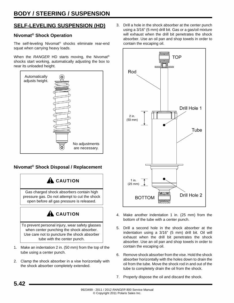
SELF-LEVELING SUSPENSION (HD)
Nivomat® Shock Operation
The self-leveling Nivomat® shocks eliminate rear-end squat when carrying heavy loads.
When the RANGER HD starts moving, the Nivomat®
shocks start working, automatically adjusting the box to near its unloaded height.
Nivomat® Shock Disposal / Replacement
1. Make an indentation 2 in. (50 mm) from the top of the tube using a center punch.
2. Clamp the shock absorber in a vise horizontally with the shock absorber completely extended.
3. Drill a hole in the shock absorber at the center punch using a 3/16” (5 mm) drill bit. Gas or a gas/oil mixture will exhaust when the drill bit penetrates the shock absorber. Use an oil pan and shop towels in order to contain the escaping oil.
4. Make another indentation 1 in. (25 mm) from the bottom of the tube with a center punch.
5. Drill a second hole in the shock absorber at the indentation using a 3/16” (5 mm) drill bit. Oil will exhaust when the drill bit penetrates the shock absorber. Use an oil pan and shop towels in order to contain the escaping oil.
6. Remove shock absorber from the vise. Hold the shock absorber horizontally with the holes down to drain the oil from the tube. Move the shock rod in and out of the tube to completely drain the oil from the shock.
7. Properly dispose the oil and discard the shock.
CAUTION
Gas charged shock absorbers contain high pressure gas. Do not attempt to cut the shock
open before all gas pressure is released.
CAUTION
To prevent personal injury, wear safety glasses when center punching the shock absorber.
Use care not to puncture the shock absorber tube with the center punch.
No adjustmentsare necessary.
Automaticallyadjusts height.
5.429923499 - 2011 / 2012 RANGER 800 Service Manual
© Copyright 2011 Polaris Sales Inc.
BODY / STEERING / SUSPENSION
5
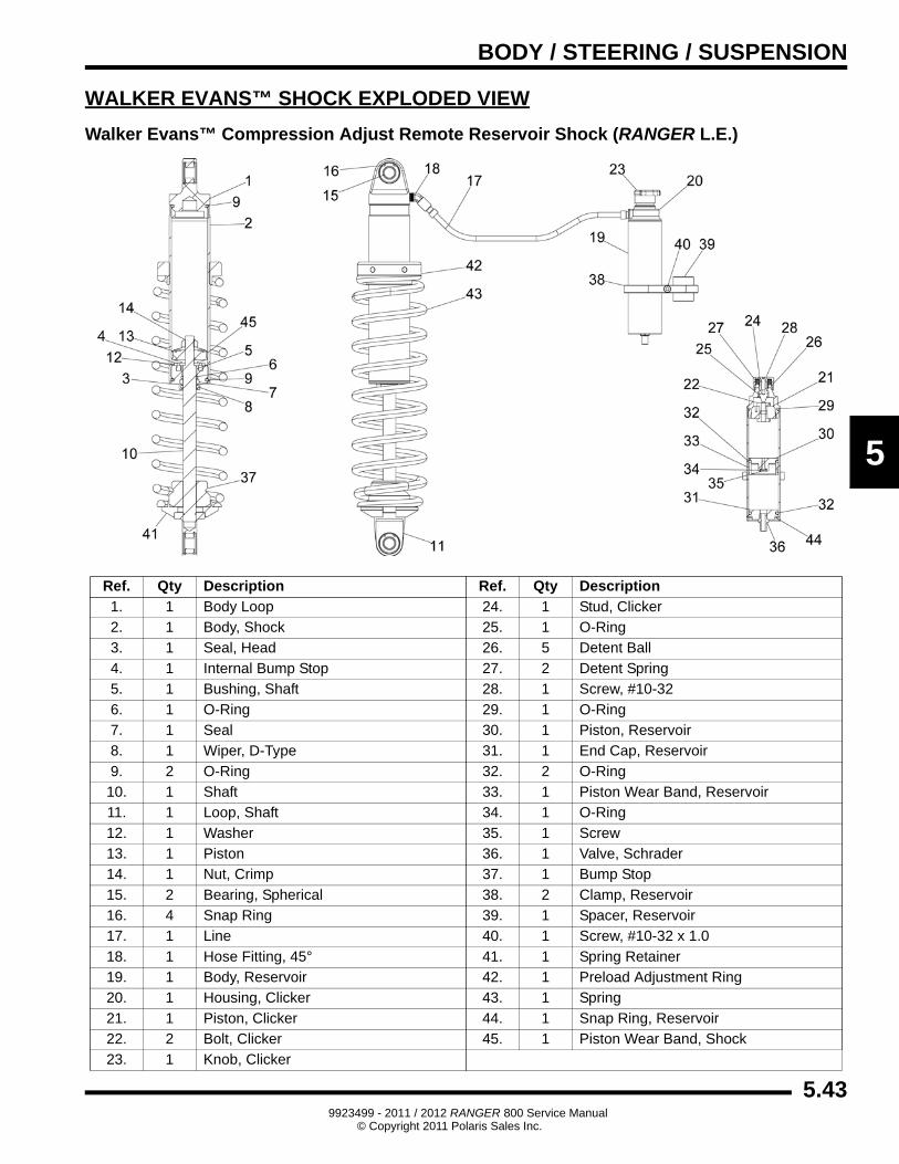
WALKER EVANS™ SHOCK EXPLODED VIEW
Walker Evans™ Compression Adjust Remote Reservoir Shock (RANGER L.E.)
Ref. Qty Description Ref. Qty Description
1. 1 Body Loop 24. 1 Stud, Clicker
2. 1 Body, Shock 25. 1 O-Ring
3. 1 Seal, Head 26. 5 Detent Ball
4. 1 Internal Bump Stop 27. 2 Detent Spring
5. 1 Bushing, Shaft 28. 1 Screw, #10-32
6. 1 O-Ring 29. 1 O-Ring
7. 1 Seal 30. 1 Piston, Reservoir
8. 1 Wiper, D-Type 31. 1 End Cap, Reservoir
9. 2 O-Ring 32. 2 O-Ring
10. 1 Shaft 33. 1 Piston Wear Band, Reservoir
11. 1 Loop, Shaft 34. 1 O-Ring
12. 1 Washer 35. 1 Screw
13. 1 Piston 36. 1 Valve, Schrader
14. 1 Nut, Crimp 37. 1 Bump Stop
15. 2 Bearing, Spherical 38. 2 Clamp, Reservoir
16. 4 Snap Ring 39. 1 Spacer, Reservoir
17. 1 Line 40. 1 Screw, #10-32 x 1.0
18. 1 Hose Fitting, 45° 41. 1 Spring Retainer
19. 1 Body, Reservoir 42. 1 Preload Adjustment Ring
20. 1 Housing, Clicker 43. 1 Spring
21. 1 Piston, Clicker 44. 1 Snap Ring, Reservoir
22. 2 Bolt, Clicker 45. 1 Piston Wear Band, Shock
23. 1 Knob, Clicker
5.439923499 - 2011 / 2012 RANGER 800 Service Manual
© Copyright 2011 Polaris Sales Inc.
BODY / STEERING / SUSPENSION
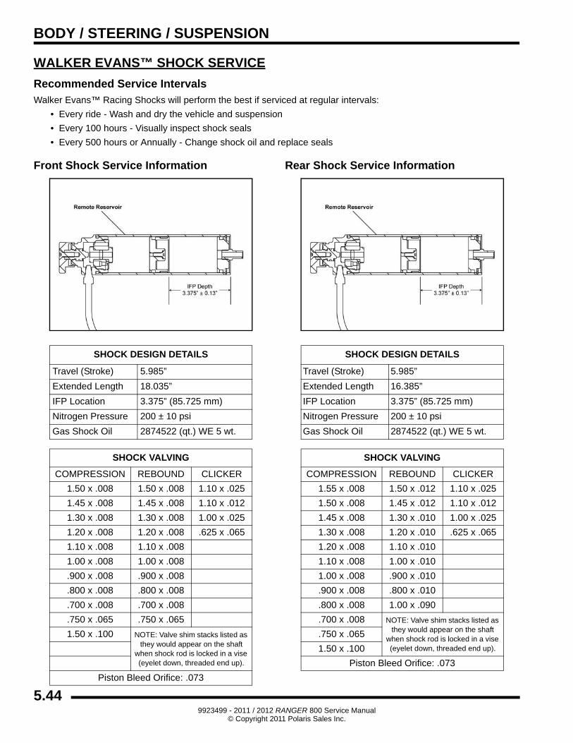
WALKER EVANS™ SHOCK SERVICE
Recommended Service IntervalsWalker Evans™ Racing Shocks will perform the best if serviced at regular intervals:
• Every ride - Wash and dry the vehicle and suspension
• Every 100 hours - Visually inspect shock seals
• Every 500 hours or Annually - Change shock oil and replace seals
Front Shock Service Information Rear Shock Service Information
SHOCK DESIGN DETAILS
Travel (Stroke) 5.985”
Extended Length 18.035”
IFP Location 3.375” (85.725 mm)
Nitrogen Pressure 200 ± 10 psi
Gas Shock Oil 2874522 (qt.) WE 5 wt.
SHOCK VALVING
COMPRESSION REBOUND CLICKER
1.50 x .008 1.50 x .008 1.10 x .025
1.45 x .008 1.45 x .008 1.10 x .012
1.30 x .008 1.30 x .008 1.00 x .025
1.20 x .008 1.20 x .008 .625 x .065
1.10 x .008 1.10 x .008
1.00 x .008 1.00 x .008
.900 x .008 .900 x .008
.800 x .008 .800 x .008
.700 x .008 .700 x .008
.750 x .065 .750 x .065
1.50 x .100 NOTE: Valve shim stacks listed as they would appear on the shaft
when shock rod is locked in a vise (eyelet down, threaded end up).
Piston Bleed Orifice: .073
SHOCK DESIGN DETAILS
Travel (Stroke) 5.985”
Extended Length 16.385”
IFP Location 3.375” (85.725 mm)
Nitrogen Pressure 200 ± 10 psi
Gas Shock Oil 2874522 (qt.) WE 5 wt.
SHOCK VALVING
COMPRESSION REBOUND CLICKER
1.55 x .008 1.50 x .012 1.10 x .025
1.50 x .008 1.45 x .012 1.10 x .012
1.45 x .008 1.30 x .010 1.00 x .025
1.30 x .008 1.20 x .010 .625 x .065
1.20 x .008 1.10 x .010
1.10 x .008 1.00 x .010
1.00 x .008 .900 x .010
.900 x .008 .800 x .010
.800 x .008 1.00 x .090
.700 x .008 NOTE: Valve shim stacks listed as they would appear on the shaft
when shock rod is locked in a vise (eyelet down, threaded end up).
.750 x .065
1.50 x .100
Piston Bleed Orifice: .073
5.449923499 - 2011 / 2012 RANGER 800 Service Manual
© Copyright 2011 Polaris Sales Inc.
BODY / STEERING / SUSPENSION
5
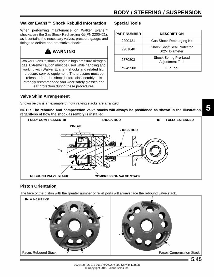
Walker Evans™ Shock Rebuild Information
When performing maintenance on Walker Evans™ shocks, use the Gas Shock Recharging Kit (PN 2200421), as it contains the necessary valves, pressure gauge, and fittings to deflate and pressurize shocks.
Special Tools
Valve Shim Arrangement
Shown below is an example of how valving stacks are arranged.
NOTE: The rebound and compression valve stacks will always be positioned as shown in the illustration, regardless of how the shock assembly is installed.
Piston Orientation
The face of the piston with the greater number of relief ports will always face the rebound valve stack.
WARNING
Walker Evans™ shocks contain high pressure nitrogen gas. Extreme caution must be used while handling and working with Walker Evans™ shocks and related high
pressure service equipment. The pressure must be released from the shock before disassembly. It is
strongly recommended you wear safety glasses and ear protection during these procedures.
PART NUMBER DESCRIPTION
2200421 Gas Shock Recharging Kit
2201640Shock Shaft Seal Protector
.625" Diameter
2870803Shock Spring Pre-Load
Adjustment Tool
PS-45908 IFP Tool
PISTON
COMPRESSION VALVE STACKREBOUND VALVE STACK
SHOCK ROD
FULLY EXTENDEDFULLY COMPRESSED SHOCK ROD
= Relief Port
Faces Rebound Stack Faces Compression Stack
5.459923499 - 2011 / 2012 RANGER 800 Service Manual
© Copyright 2011 Polaris Sales Inc.
BODY / STEERING / SUSPENSION
Walker Evans™ Shock Disassembly
IMPORTANT: To prevent damage or marks to the shock, the use of soft jaws on a vise is recommended.
1. Clean and carefully remove shock from the vehicle.
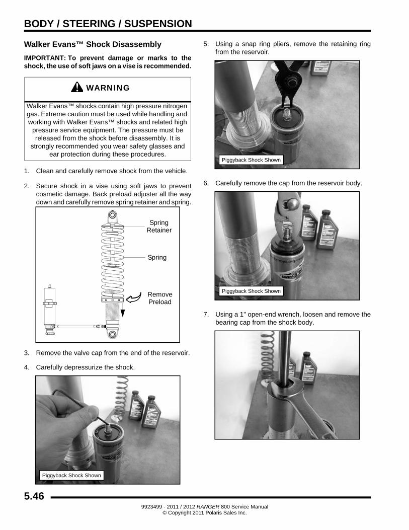
2. Secure shock in a vise using soft jaws to prevent cosmetic damage. Back preload adjuster all the way down and carefully remove spring retainer and spring.
3. Remove the valve cap from the end of the reservoir.
4. Carefully depressurize the shock.
5. Using a snap ring pliers, remove the retaining ring from the reservoir.
6. Carefully remove the cap from the reservoir body.
7. Using a 1" open-end wrench, loosen and remove the bearing cap from the shock body.
WARNING
Walker Evans™ shocks contain high pressure nitrogen gas. Extreme caution must be used while handling and working with Walker Evans™ shocks and related high
pressure service equipment. The pressure must be released from the shock before disassembly. It is
strongly recommended you wear safety glasses and ear protection during these procedures.
RemovePreload
SpringRetainer
Spring
Piggyback Shock Shown
Piggyback Shock Shown
Piggyback Shock Shown
5.469923499 - 2011 / 2012 RANGER 800 Service Manual
© Copyright 2011 Polaris Sales Inc.
BODY / STEERING / SUSPENSION
5
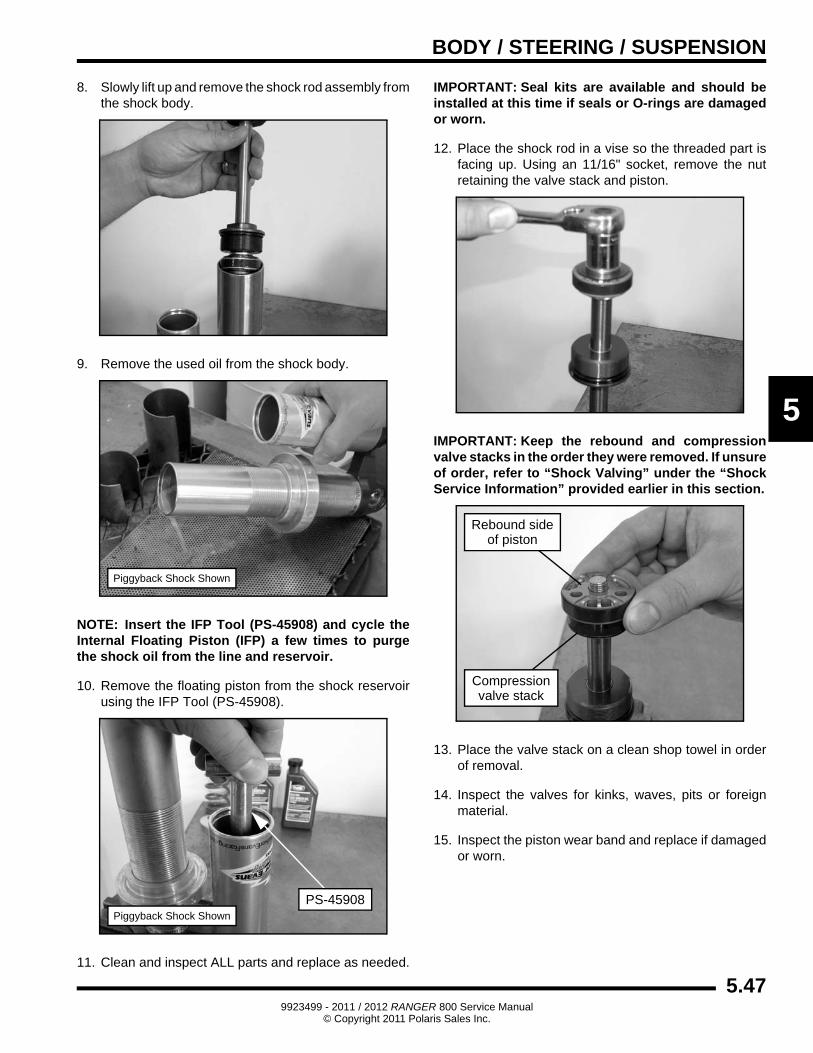
8. Slowly lift up and remove the shock rod assembly from the shock body.
9. Remove the used oil from the shock body.
NOTE: Insert the IFP Tool (PS-45908) and cycle the Internal Floating Piston (IFP) a few times to purge the shock oil from the line and reservoir.
10. Remove the floating piston from the shock reservoir using the IFP Tool (PS-45908).
11. Clean and inspect ALL parts and replace as needed.
IMPORTANT: Seal kits are available and should be installed at this time if seals or O-rings are damaged or worn.
12. Place the shock rod in a vise so the threaded part is facing up. Using an 11/16" socket, remove the nut retaining the valve stack and piston.
IMPORTANT: Keep the rebound and compression valve stacks in the order they were removed. If unsure of order, refer to “Shock Valving” under the “Shock Service Information” provided earlier in this section.
13. Place the valve stack on a clean shop towel in order of removal.
14. Inspect the valves for kinks, waves, pits or foreign material.
15. Inspect the piston wear band and replace if damaged or worn.
Piggyback Shock Shown
PS-45908Piggyback Shock Shown
Rebound sideof piston
Compressionvalve stack
5.479923499 - 2011 / 2012 RANGER 800 Service Manual
© Copyright 2011 Polaris Sales Inc.
BODY / STEERING / SUSPENSION
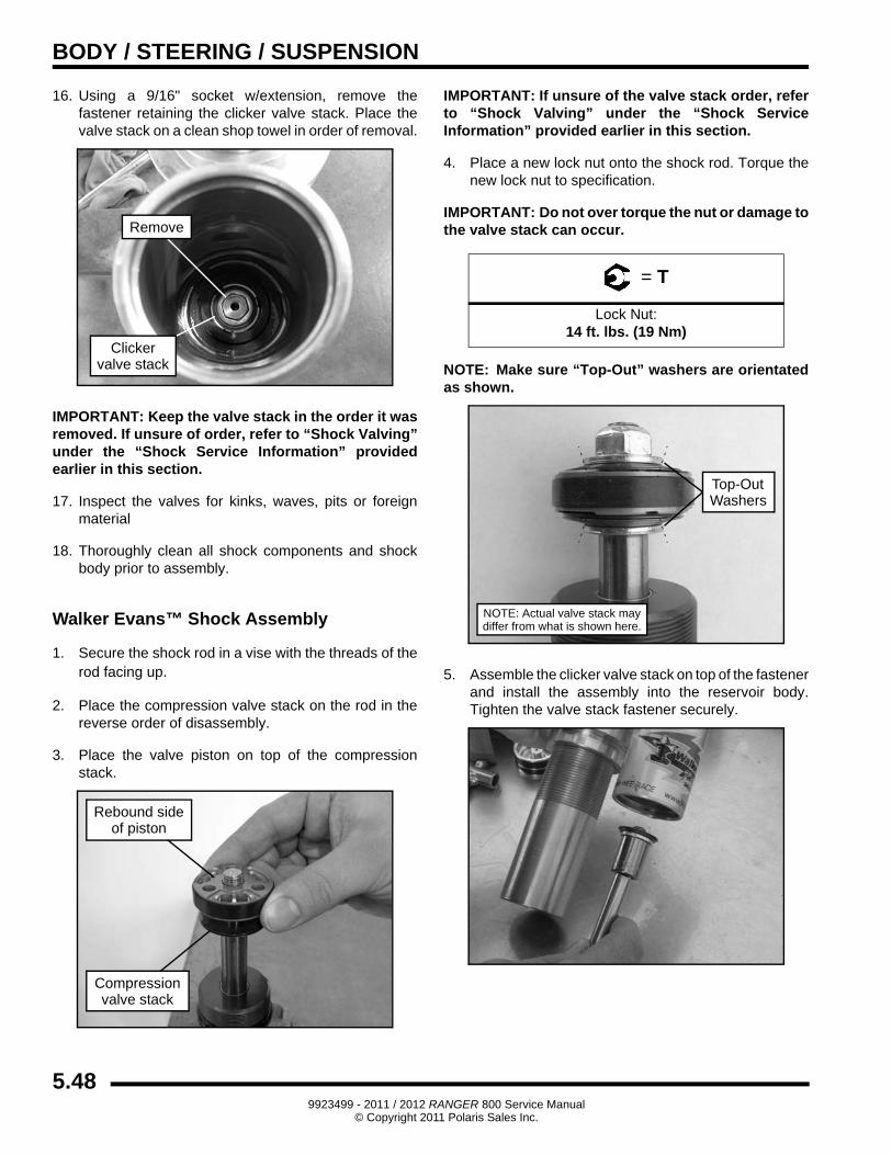
16. Using a 9/16" socket w/extension, remove the fastener retaining the clicker valve stack. Place the valve stack on a clean shop towel in order of removal.
IMPORTANT: Keep the valve stack in the order it was removed. If unsure of order, refer to “Shock Valving” under the “Shock Service Information” provided earlier in this section.
17. Inspect the valves for kinks, waves, pits or foreign material
18. Thoroughly clean all shock components and shock body prior to assembly.
Walker Evans™ Shock Assembly
1. Secure the shock rod in a vise with the threads of the rod facing up.
2. Place the compression valve stack on the rod in the reverse order of disassembly.
3. Place the valve piston on top of the compression stack.
IMPORTANT: If unsure of the valve stack order, refer to “Shock Valving” under the “Shock Service Information” provided earlier in this section.
4. Place a new lock nut onto the shock rod. Torque the new lock nut to specification.
IMPORTANT: Do not over torque the nut or damage to the valve stack can occur.
NOTE: Make sure “Top-Out” washers are orientated as shown.
5. Assemble the clicker valve stack on top of the fastener and install the assembly into the reservoir body. Tighten the valve stack fastener securely.
Remove
Clickervalve stack
Rebound sideof piston
Compressionvalve stack
= T
Lock Nut:14 ft. lbs. (19 Nm)
NOTE: Actual valve stack may
Top-OutWashers
differ from what is shown here.
5.489923499 - 2011 / 2012 RANGER 800 Service Manual
© Copyright 2011 Polaris Sales Inc.
BODY / STEERING / SUSPENSION
5
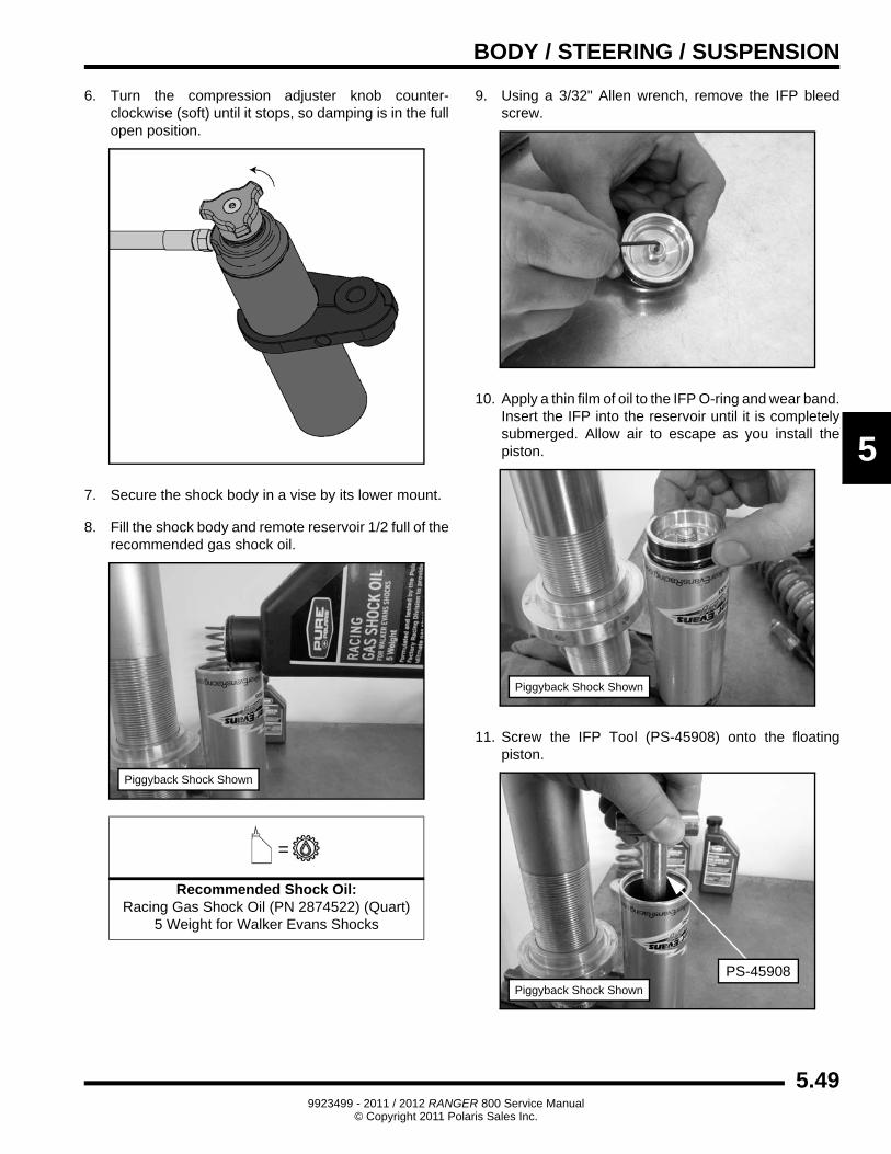
6. Turn the compression adjuster knob counter-clockwise (soft) until it stops, so damping is in the full open position.
7. Secure the shock body in a vise by its lower mount.
8. Fill the shock body and remote reservoir 1/2 full of the recommended gas shock oil.
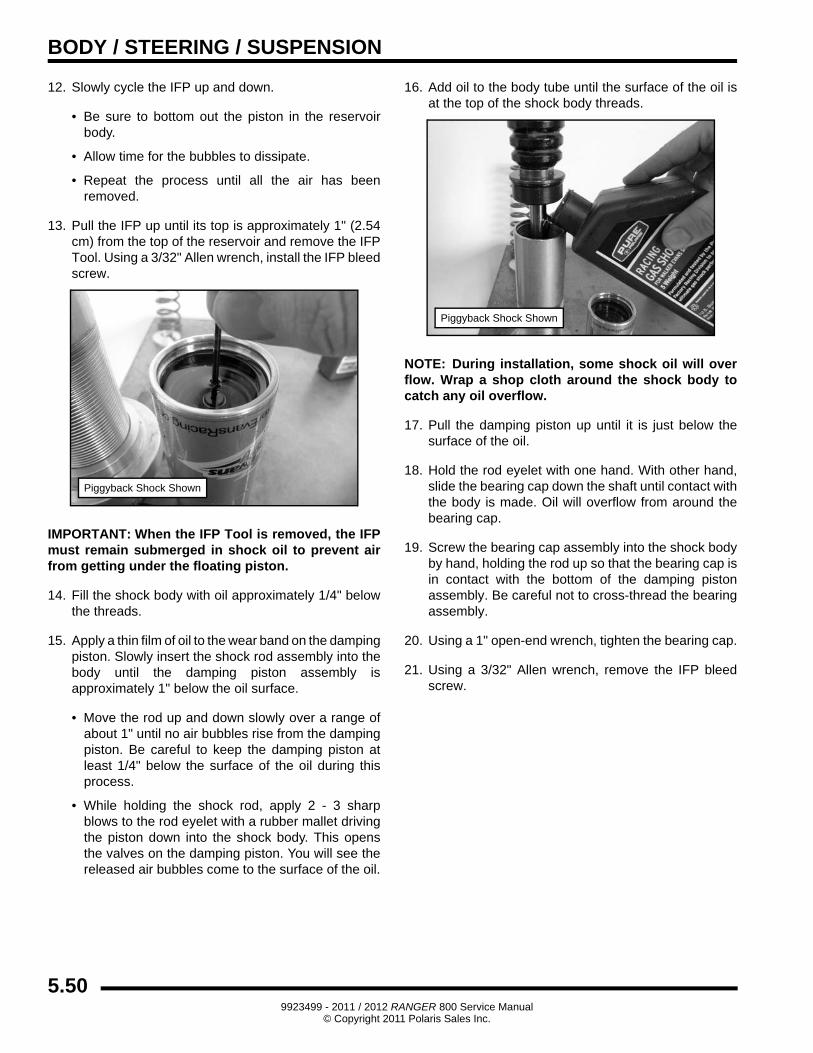
9. Using a 3/32" Allen wrench, remove the IFP bleed screw.
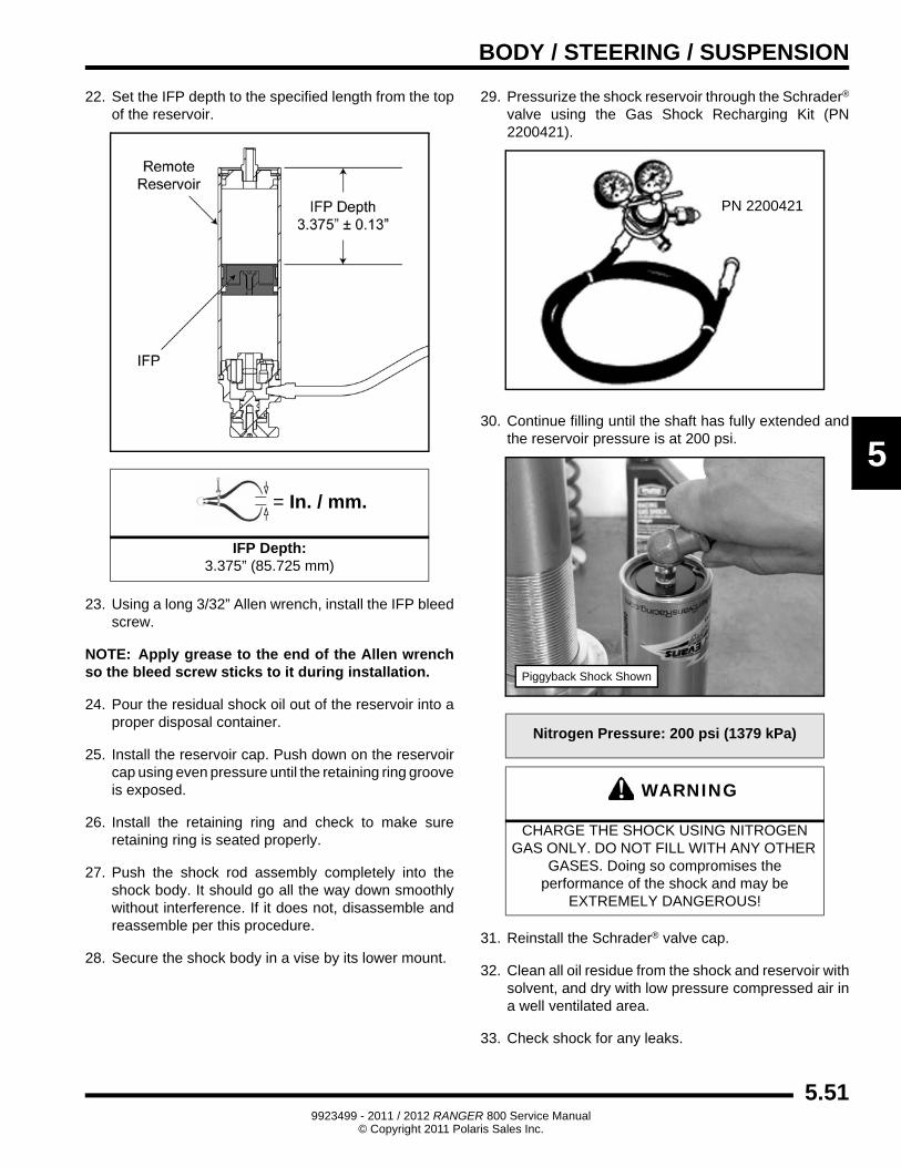
10. Apply a thin film of oil to the IFP O-ring and wear band. Insert the IFP into the reservoir until it is completely submerged. Allow air to escape as you install the piston.
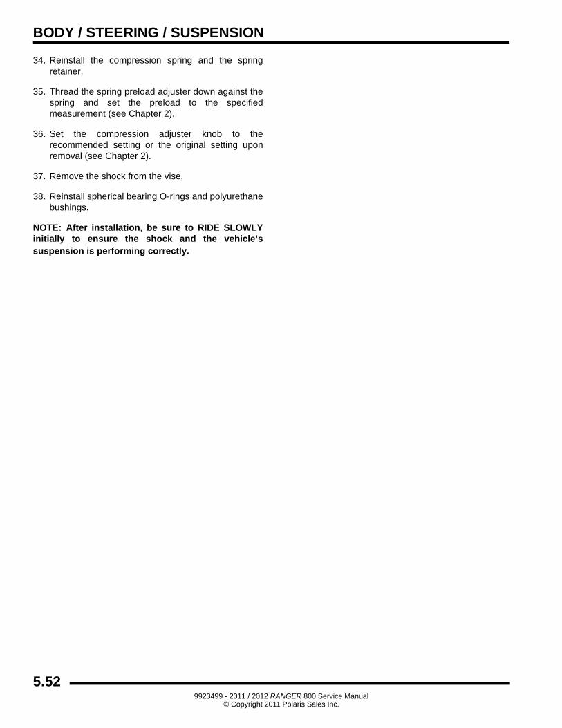
11. Screw the IFP Tool (PS-45908) onto the floating piston.
=
Recommended Shock Oil:Racing Gas Shock Oil (PN 2874522) (Quart)
5 Weight for Walker Evans Shocks
Piggyback Shock Shown
Piggyback Shock Shown
PS-45908Piggyback Shock Shown
5.499923499 - 2011 / 2012 RANGER 800 Service Manual
© Copyright 2011 Polaris Sales Inc.
BODY / STEERING / SUSPENSION
12. Slowly cycle the IFP up and down.
• Be sure to bottom out the piston in the reservoir body.
• Allow time for the bubbles to dissipate.
• Repeat the process until all the air has been removed.
13. Pull the IFP up until its top is approximately 1" (2.54 cm) from the top of the reservoir and remove the IFP Tool. Using a 3/32" Allen wrench, install the IFP bleed screw.
IMPORTANT: When the IFP Tool is removed, the IFP must remain submerged in shock oil to prevent air from getting under the floating piston.
14. Fill the shock body with oil approximately 1/4" below the threads.
15. Apply a thin film of oil to the wear band on the damping piston. Slowly insert the shock rod assembly into the body until the damping piston assembly is approximately 1" below the oil surface.
• Move the rod up and down slowly over a range of about 1" until no air bubbles rise from the damping piston. Be careful to keep the damping piston at least 1/4" below the surface of the oil during this process.
• While holding the shock rod, apply 2 - 3 sharp blows to the rod eyelet with a rubber mallet driving the piston down into the shock body. This opens the valves on the damping piston. You will see the released air bubbles come to the surface of the oil.
16. Add oil to the body tube until the surface of the oil is at the top of the shock body threads.
NOTE: During installation, some shock oil will over flow. Wrap a shop cloth around the shock body to catch any oil overflow.
17. Pull the damping piston up until it is just below the surface of the oil.
18. Hold the rod eyelet with one hand. With other hand, slide the bearing cap down the shaft until contact with the body is made. Oil will overflow from around the bearing cap.
19. Screw the bearing cap assembly into the shock body by hand, holding the rod up so that the bearing cap is in contact with the bottom of the damping piston assembly. Be careful not to cross-thread the bearing assembly.
20. Using a 1" open-end wrench, tighten the bearing cap.
21. Using a 3/32" Allen wrench, remove the IFP bleed screw.
Piggyback Shock Shown
Piggyback Shock Shown
5.509923499 - 2011 / 2012 RANGER 800 Service Manual
© Copyright 2011 Polaris Sales Inc.
BODY / STEERING / SUSPENSION
5
22. Set the IFP depth to the specified length from the top of the reservoir.
23. Using a long 3/32” Allen wrench, install the IFP bleed screw.
NOTE: Apply grease to the end of the Allen wrench so the bleed screw sticks to it during installation.
24. Pour the residual shock oil out of the reservoir into a proper disposal container.
25. Install the reservoir cap. Push down on the reservoir cap using even pressure until the retaining ring groove is exposed.
26. Install the retaining ring and check to make sure retaining ring is seated properly.
27. Push the shock rod assembly completely into the shock body. It should go all the way down smoothly without interference. If it does not, disassemble and reassemble per this procedure.
28. Secure the shock body in a vise by its lower mount.
29. Pressurize the shock reservoir through the Schrader®
valve using the Gas Shock Recharging Kit (PN 2200421).
30. Continue filling until the shaft has fully extended and the reservoir pressure is at 200 psi.
31. Reinstall the Schrader® valve cap.
32. Clean all oil residue from the shock and reservoir with solvent, and dry with low pressure compressed air in a well ventilated area.
33. Check shock for any leaks.
= In. / mm.
IFP Depth:3.375” (85.725 mm)
Nitrogen Pressure: 200 psi (1379 kPa)
WARNING
CHARGE THE SHOCK USING NITROGEN GAS ONLY. DO NOT FILL WITH ANY OTHER
GASES. Doing so compromises the performance of the shock and may be
EXTREMELY DANGEROUS!
PN 2200421
Piggyback Shock Shown
5.519923499 - 2011 / 2012 RANGER 800 Service Manual
© Copyright 2011 Polaris Sales Inc.
BODY / STEERING / SUSPENSION
34. Reinstall the compression spring and the spring retainer.
35. Thread the spring preload adjuster down against the spring and set the preload to the specified measurement (see Chapter 2).
36. Set the compression adjuster knob to the recommended setting or the original setting upon removal (see Chapter 2).
37. Remove the shock from the vise.
38. Reinstall spherical bearing O-rings and polyurethane bushings.
NOTE: After installation, be sure to RIDE SLOWLY initially to ensure the shock and the vehicle’s suspension is performing correctly.
5.529923499 - 2011 / 2012 RANGER 800 Service Manual
© Copyright 2011 Polaris Sales Inc.