Embed Size (px)
Citation preview
1/17
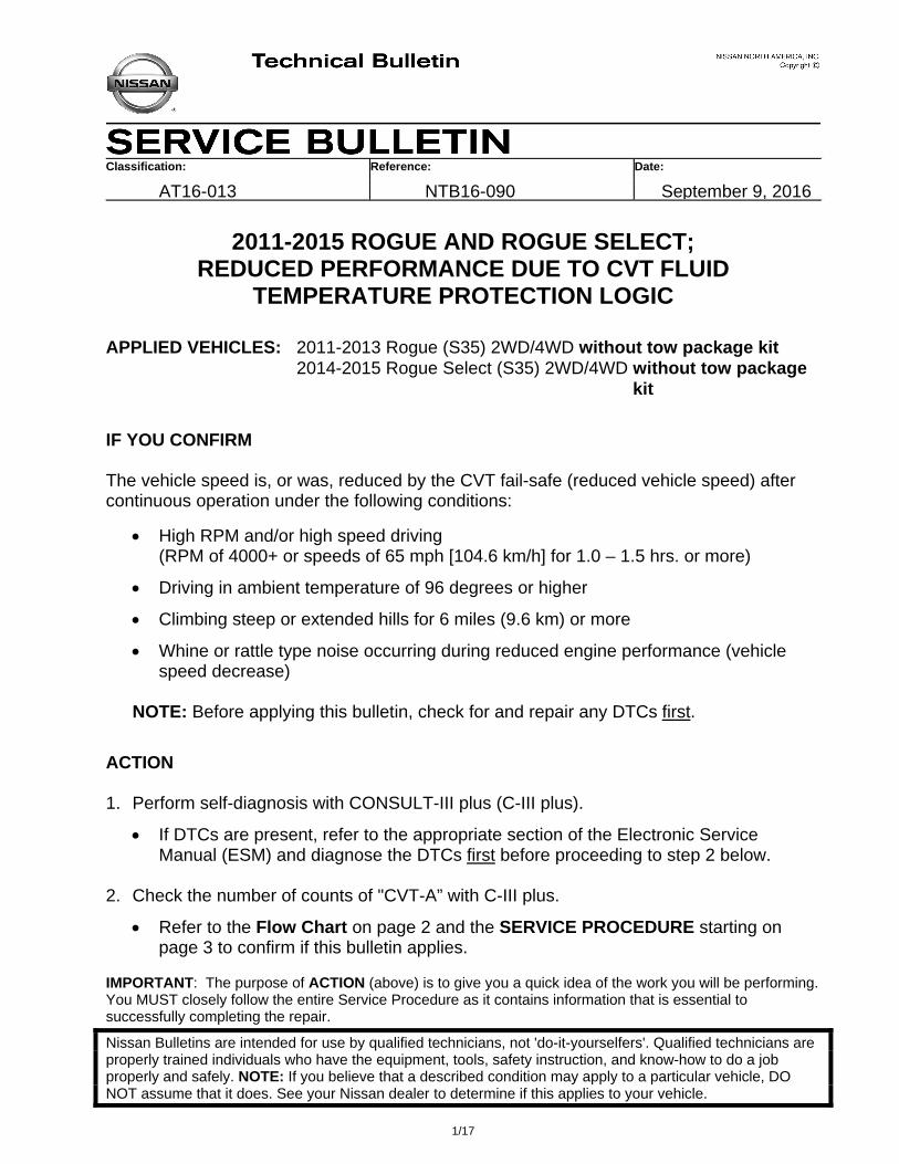
Classification: Reference: Date:
AT16-013 NTB16-090 September 9, 2016
2011-2015 ROGUE AND ROGUE SELECT; REDUCED PERFORMANCE DUE TO CVT FLUID
TEMPERATURE PROTECTION LOGIC
APPLIED VEHICLES: 2011-2013 Rogue (S35) 2WD/4WD without tow package kit 2014-2015 Rogue Select (S35) 2WD/4WD without tow package kit
IF YOU CONFIRM The vehicle speed is, or was, reduced by the CVT fail-safe (reduced vehicle speed) after continuous operation under the following conditions:
High RPM and/or high speed driving (RPM of 4000+ or speeds of 65 mph [104.6 km/h] for 1.0 – 1.5 hrs. or more)
Driving in ambient temperature of 96 degrees or higher
Climbing steep or extended hills for 6 miles (9.6 km) or more
Whine or rattle type noise occurring during reduced engine performance (vehicle speed decrease)
NOTE: Before applying this bulletin, check for and repair any DTCs first.
ACTION 1. Perform self-diagnosis with CONSULT-III plus (C-III plus).
If DTCs are present, refer to the appropriate section of the Electronic Service Manual (ESM) and diagnose the DTCs first before proceeding to step 2 below.
2. Check the number of counts of "CVT-A” with C-III plus.
Refer to the Flow Chart on page 2 and the SERVICE PROCEDURE starting on page 3 to confirm if this bulletin applies.
IMPORTANT: The purpose of ACTION (above) is to give you a quick idea of the work you will be performing. You MUST closely follow the entire Service Procedure as it contains information that is essential to successfully completing the repair.
Nissan Bulletins are intended for use by qualified technicians, not 'do-it-yourselfers'. Qualified technicians are properly trained individuals who have the equipment, tools, safety instruction, and know-how to do a job properly and safely. NOTE: If you believe that a described condition may apply to a particular vehicle, DO NOT assume that it does. See your Nissan dealer to determine if this applies to your vehicle.
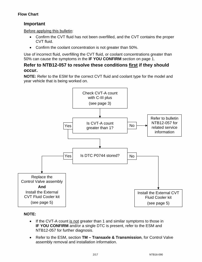
Flow Chart
Important
Before applying this bulletin:
Confirm the CVT fluid has not been overfilled, and the CVT contains the proper CVT fluid.
Confirm the coolant concentration is not greater than 50%.
Use of incorrect fluid, overfilling the CVT fluid, or coolant concentrations greater than 50% can cause the symptoms in the IF YOU CONFIRM section on page 1.
Refer to NTB12-057 to resolve these conditions first if they should occur.
NOTE: Refer to the ESM for the correct CVT fluid and coolant type for the model and year vehicle that is being worked on.
Yes
Is DTC P0744 stored?
Refer to bulletin NTB12-057 for related service
information
Replace the Control Valve assembly
And
Install the External CVT Fluid Cooler kit
(see page 5)
Is CVT-A count greater than 1?
No
NoYes
Install the External CVT Fluid Cooler kit
(see page 5)
Check CVT-A count with C-III plus
(see page 3)
NOTE:
If the CVT-A count is not greater than 1 and similar symptoms to those in IF YOU CONFIRM and/or a single DTC is present, refer to the ESM and NTB12-057 for further diagnosis.
Refer to the ESM, section TM – Transaxle & Transmission, for Control Valve assembly removal and installation information.
2/17 NTB16-090
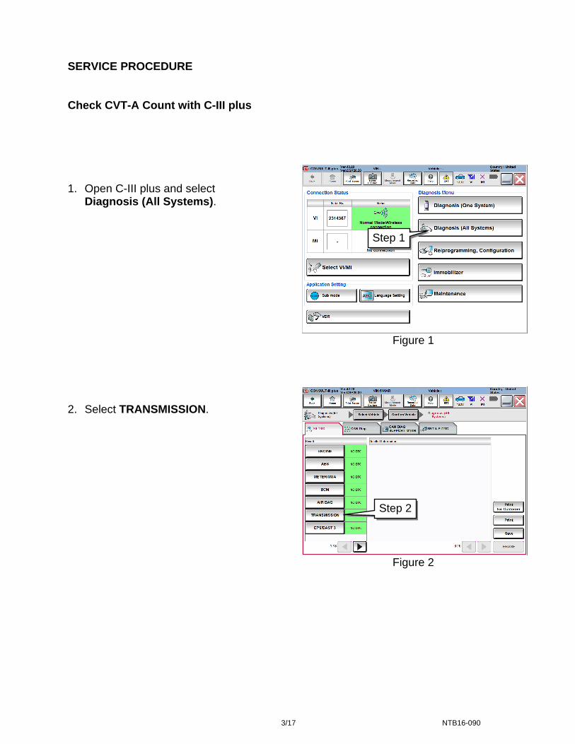
SERVICE PROCEDURE Check CVT-A Count with C-III plus
1. Open C-III plus and select
Diagnosis (All Systems). 2. Select TRANSMISSION.
Step 1
Figure 1
Step 2
Figure 2
3/17 NTB16-090
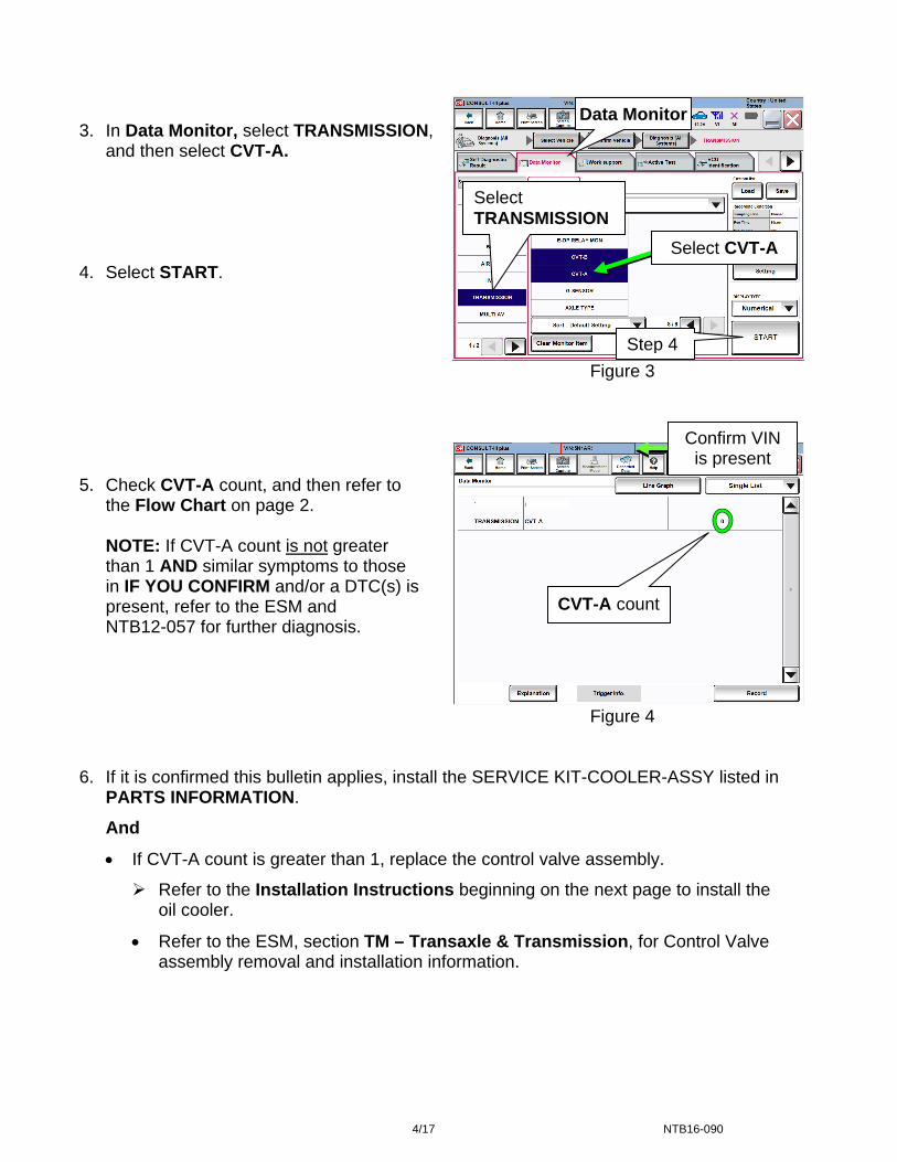
Figure 3
Figure 4
3. In Data Monitor, select TRANSMISSION,
and then select CVT-A. 4. Select START.
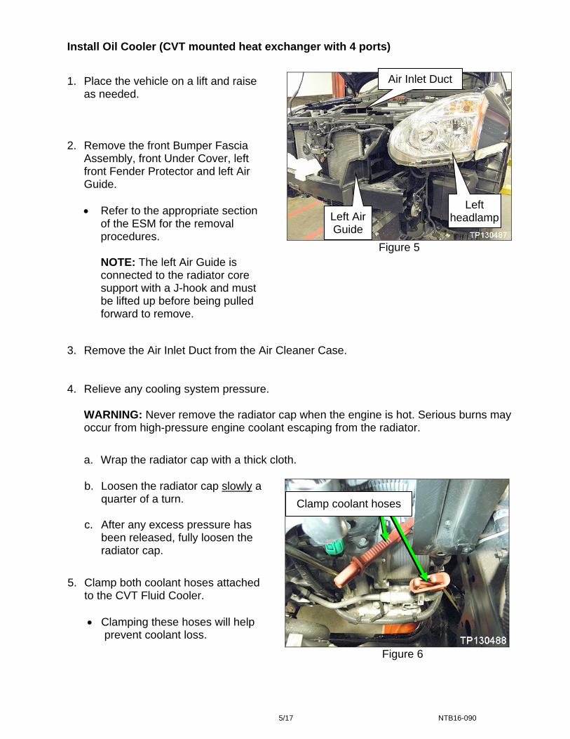
5. Check CVT-A count, and then refer to the Flow Chart on page 2.
NOTE: If CVT-A count is not greater than 1 AND similar symptoms to those in IF YOU CONFIRM and/or a DTC(s) is present, refer to the ESM and NTB12-057 for further diagnosis.
Select CVT-A
CVT-A count
Step 4
Select TRANSMISSION
Confirm VIN is present
Data Monitor
6. If it is confirmed this bulletin applies, install the SERVICE KIT-COOLER-ASSY listed in
PARTS INFORMATION.
And
If CVT-A count is greater than 1, replace the control valve assembly.
Refer to the Installation Instructions beginning on the next page to install the oil cooler.
Refer to the ESM, section TM – Transaxle & Transmission, for Control Valve assembly removal and installation information.
4/17 NTB16-090
Install Oil Cooler (CVT mounted heat exchanger with 4 ports)
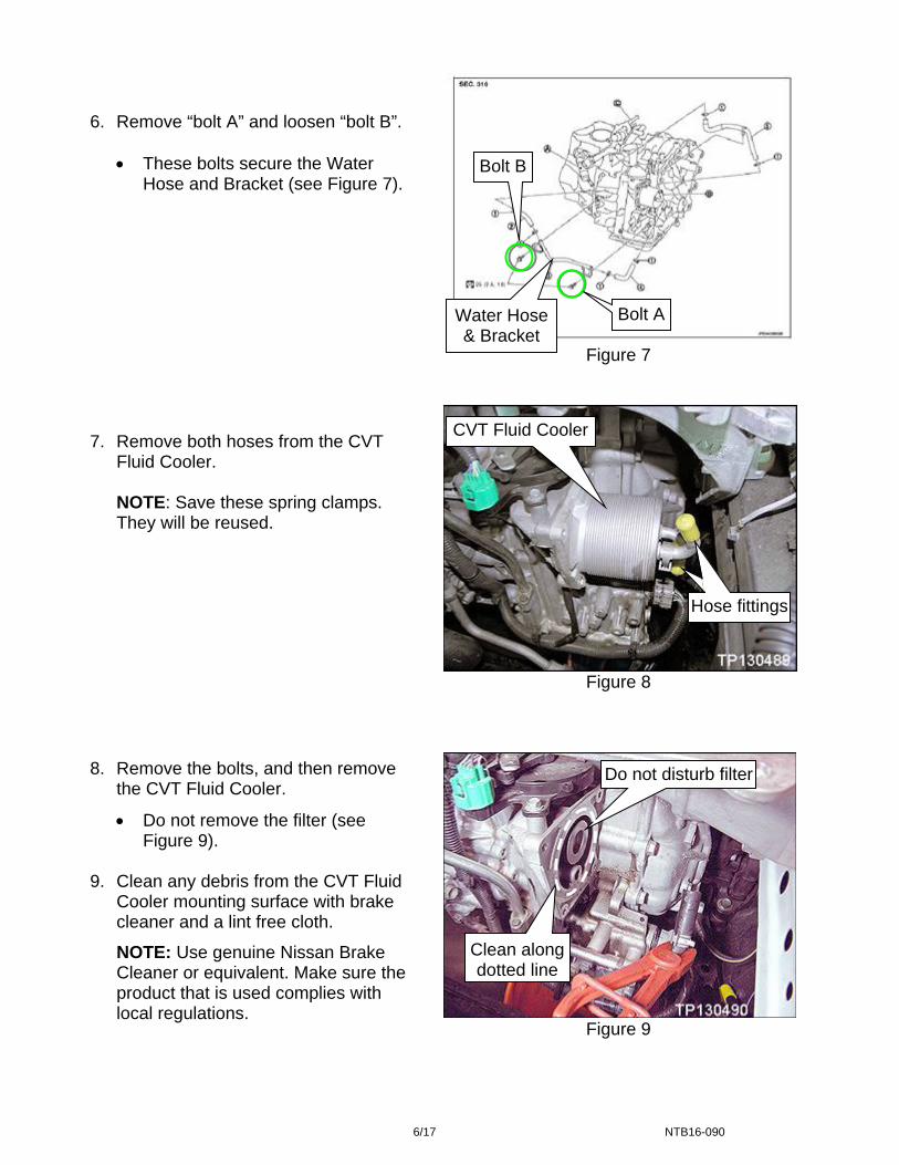
Air Inlet Duct 1. Place the vehicle on a lift and raise as needed.
2. Remove the front Bumper Fascia
Assembly, front Under Cover, left front Fender Protector and left Air Guide.
Refer to the appropriate section of the ESM for the removal procedures.
NOTE: The left Air Guide is connected to the radiator core support with a J-hook and must be lifted up before being pulled forward to remove.
Left headlampLeft Air
Guide
Figure 5
3. Remove the Air Inlet Duct from the Air Cleaner Case. 4. Relieve any cooling system pressure.
WARNING: Never remove the radiator cap when the engine is hot. Serious burns may occur from high-pressure engine coolant escaping from the radiator.
a. Wrap the radiator cap with a thick cloth.
b. Loosen the radiator cap slowly a quarter of a turn.
c. After any excess pressure has
been released, fully loosen the radiator cap.
5. Clamp both coolant hoses attached to the CVT Fluid Cooler.
Clamping these hoses will help
prevent coolant loss.
Clamp coolant hoses
Figure 6
5/17 NTB16-090
These bolts secure the Water Hose and Bracket (see Figure 7).
6. Remove “bolt A” and loosen “bolt B”.
Figure 7
Bolt B
CVT Fluid Cooler
Bolt A Water Hose & Bracket
Figure 8
8. Remove the bolts, and then remove the CVT Fluid Cooler.
Do not remove the filter (see Figure 9).
9. Clean any debris from the CVT Fluid
Cooler mounting surface with brake cleaner and a lint free cloth.
NOTE: Use genuine Nissan Brake Cleaner or equivalent. Make sure the product that is used complies with local regulations.
7. Remove both hoses from the CVT
Fluid Cooler.
NOTE: Save these spring clamps. They will be reused.
Clean along dotted line
Do not disturb filter
Hose ti
Hose fittings
Figure 9
6/17 NTB16-090
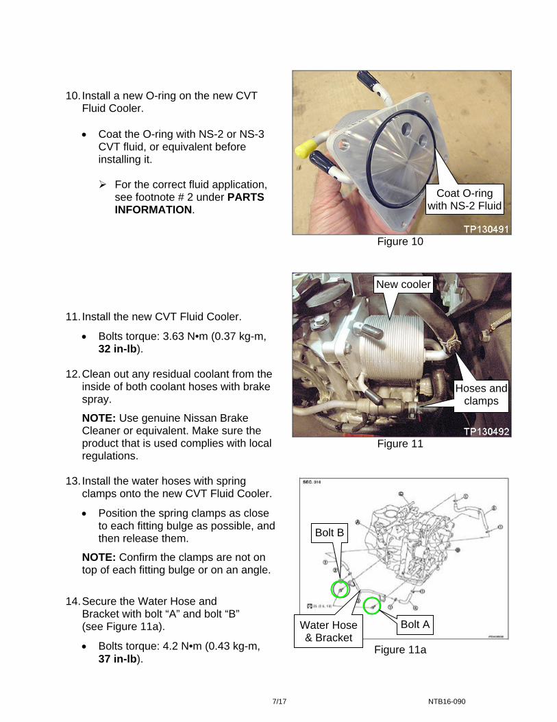
Figure 10
Figure 11
10. Install a new O-ring on the new CVT
Fluid Cooler.
Coat the O-ring with NS-2 or NS-3 CVT fluid, or equivalent before installing it.
For the correct fluid application,
see footnote # 2 under PARTS INFORMATION.
11. Install the new CVT Fluid Cooler.
Bolts torque: 3.63 N•m (0.37 kg-m, 32 in-lb).
12. Clean out any residual coolant from the
inside of both coolant hoses with brake spray.
NOTE: Use genuine Nissan Brake Cleaner or equivalent. Make sure the product that is used complies with local regulations.
13. Install the water hoses with spring clamps onto the new CVT Fluid Cooler.
Position the spring clamps as close to each fitting bulge as possible, and then release them.
NOTE: Confirm the clamps are not on top of each fitting bulge or on an angle.
14. Secure the Water Hose and Bracket with bolt “A” and bolt “B” (see Figure 11a).
Bolts torque: 4.2 N•m (0.43 kg-m, 37 in-lb).
Coat O-ring with NS-2 Fluid
New cooler
Figure 11a
Hoses and clamps
Hoses and clamps
Bolt A Water Hose & Bracket
Bolt B
7/17 NTB16-090
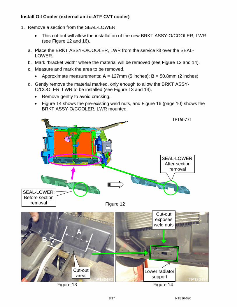
Install Oil Cooler (external air-to-ATF CVT cooler) 1. Remove a section from the SEAL-LOWER.
This cut-out will allow the installation of the new BRKT ASSY-O/COOLER, LWR (see Figure 12 and 16).
a. Place the BRKT ASSY-O/COOLER, LWR from the service kit over the SEAL-LOWER.
b. Mark “bracket width” where the material will be removed (see Figure 12 and 14).
c. Measure and mark the area to be removed.
Approximate measurements: A = 127mm (5 inches); B = 50.8mm (2 inches)
d. Gently remove the material marked, only enough to allow the BRKT ASSY-O/COOLER, LWR to be installed (see Figure 13 and 14).
Remove gently to avoid cracking.
Figure 14 shows the pre-existing weld nuts, and Figure 16 (page 10) shows the BRKT ASSY-O/COOLER, LWR mounted.
Figure 12
Cut-out area
Cut-out exposes weld nuts
SEAL-LOWER: Before section
removal
SEAL-LOWER: After section
removal
Lower radiator support
A B
Figure 13 Figure 14
8/17 NTB16-090
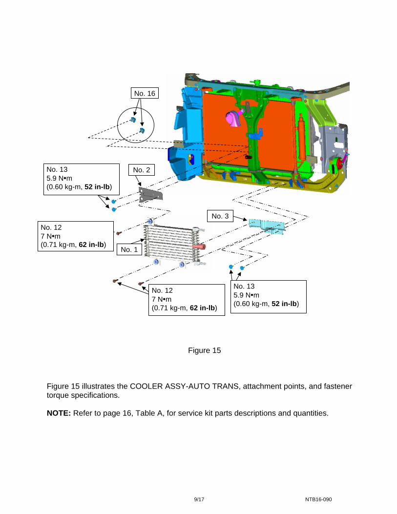
No. 1
No. 2 No. 13 5.9 N•m (0.60 kg-m, 52 in-lb)
No. 13 5.9 N•m (0.60 kg-m, 52 in-lb)
No. 12 7 N•m (0.71 kg-m, 62 in-lb)
No. 12 7 N•m
No. 16
No. 3
(0.71 kg-m, 62 in-lb)
Figure 15 Figure 15 illustrates the COOLER ASSY-AUTO TRANS, attachment points, and fastener torque specifications. NOTE: Refer to page 16, Table A, for service kit parts descriptions and quantities.
9/17 NTB16-090
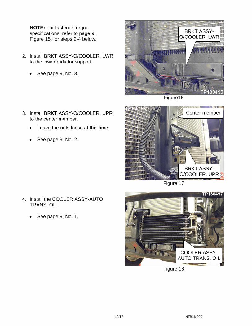
NOTE: For fastener torque specifications, refer to page 9, Figure 15, for steps 2-4 below.
2. Install BRKT ASSY-O/COOLER, LWR
to the lower radiator support.
See page 9, No. 3. 3. Install BRKT ASSY-O/COOLER, UPR
to the center member.
Leave the nuts loose at this time.
See page 9, No. 2.
4. Install the COOLER ASSY-AUTO TRANS, OIL.
See page 9, No. 1.
Figure16
Figure 17
BRKT ASSY-O/COOLER, LWR
BRKT ASSY-O/COOLER, UPR
COOLER ASSY-AUTO TRANS, OIL
Center member
Figure 18
10/17 NTB16-090
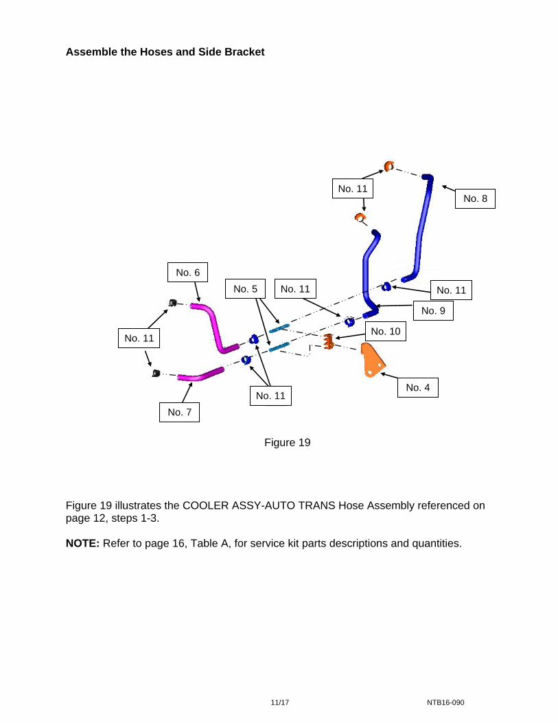
Assemble the Hoses and Side Bracket
NO.8
NO.9
NO.15
NO.11 NO.1
No. 11 No. 8
NO.6
1
NO.4
NO.5
NO.7
NO.10
NO.11
No. 6
No. 5 No. 11 No. 11
No. 9
No. 10 No. 11
No. 4 NO.11
No. 11
No. 7
Figure 19 Figure 19 illustrates the COOLER ASSY-AUTO TRANS Hose Assembly referenced on page 12, steps 1-3. NOTE: Refer to page 16, Table A, for service kit parts descriptions and quantities.
11/17 NTB16-090
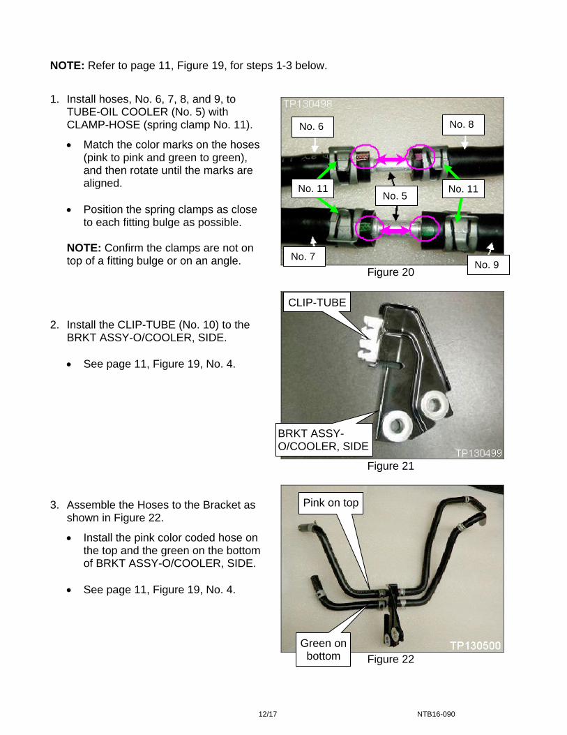
NOTE: Refer to page 11, Figure 19, for steps 1-3 below.
1. Install hoses, No. 6, 7, 8, and 9, to
TUBE-OIL COOLER (No. 5) with CLAMP-HOSE (spring clamp No. 11).
Match the color marks on the hoses (pink to pink and green to green), and then rotate until the marks are aligned.
Position the spring clamps as close
to each fitting bulge as possible.
NOTE: Confirm the clamps are not on top of a fitting bulge or on an angle.
2. Install the CLIP-TUBE (No. 10) to the
BRKT ASSY-O/COOLER, SIDE.
See page 11, Figure 19, No. 4. 3. Assemble the Hoses to the Bracket as
shown in Figure 22.
Install the pink color coded hose on the top and the green on the bottom of BRKT ASSY-O/COOLER, SIDE.
See page 11, Figure 19, No. 4.
No. 8 No. 6
No. 5 No. 11 No. 11
No. 7 No. 9
Figure 20
CLIP-TUBE
BRKT ASSY-O/COOLER, SIDE
Figure 21
Pink on top
Figure 22
Green on bottom
12/17 NTB16-090
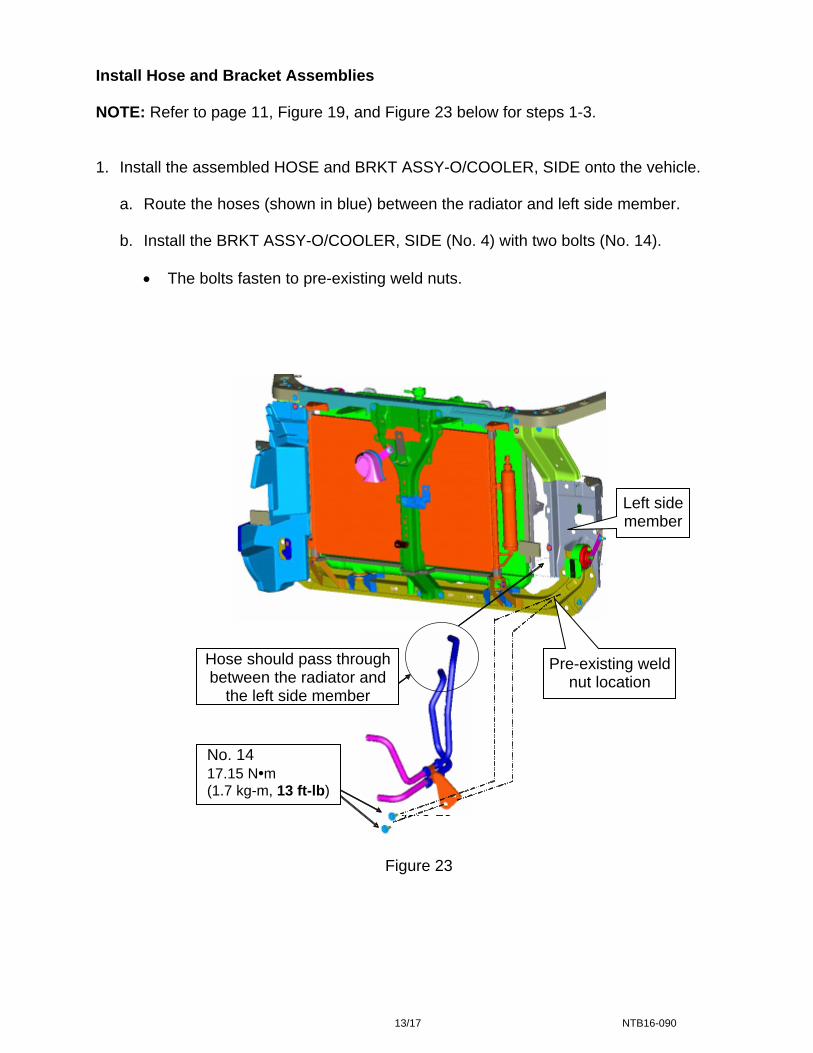
Install Hose and Bracket Assemblies NOTE: Refer to page 11, Figure 19, and Figure 23 below for steps 1-3. 1. Install the assembled HOSE and BRKT ASSY-O/COOLER, SIDE onto the vehicle.
a. Route the hoses (shown in blue) between the radiator and left side member.
b. Install the BRKT ASSY-O/COOLER, SIDE (No. 4) with two bolts (No. 14). The bolts fasten to pre-existing weld nuts.
Figure 19
Left side member
Pre-existing weld nut location
Hose should pass through between the radiator and
the left side member
No. 14 17.15 N•m (1.7 kg-m, 13 ft-lb)
Figure 23
13/17 NTB16-090
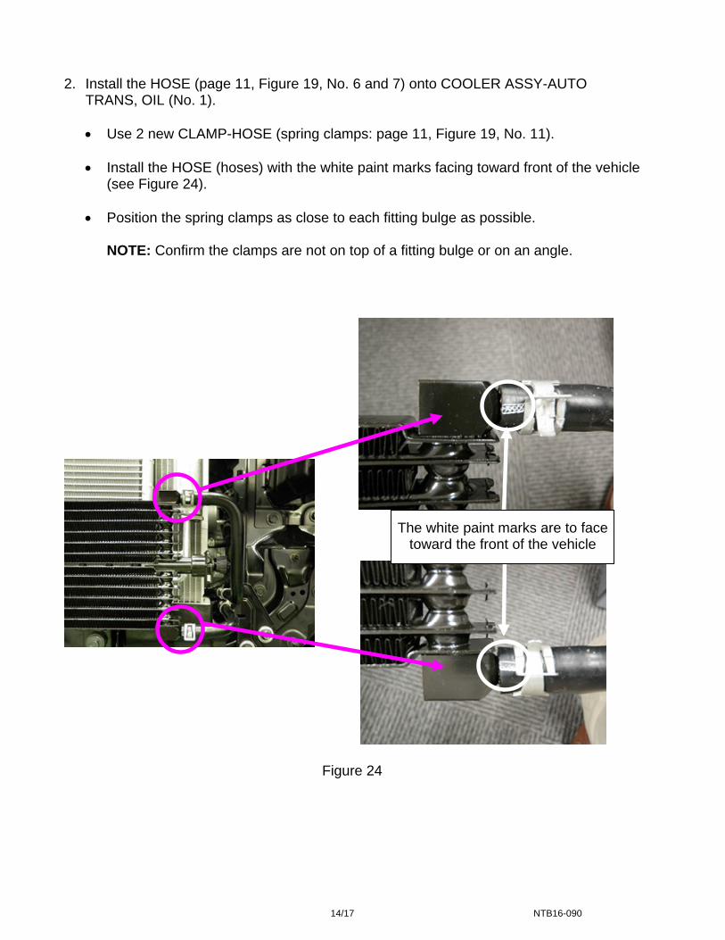
2. Install the HOSE (page 11, Figure 19, No. 6 and 7) onto COOLER ASSY-AUTO
TRANS, OIL (No. 1).
Use 2 new CLAMP-HOSE (spring clamps: page 11, Figure 19, No. 11).
Install the HOSE (hoses) with the white paint marks facing toward front of the vehicle (see Figure 24).
Position the spring clamps as close to each fitting bulge as possible.
NOTE: Confirm the clamps are not on top of a fitting bulge or on an angle.
White Paint mark shoud betorward vehicle front side
The white paint marks are to face toward the front of the vehicle
Figure 24
14/17 NTB16-090
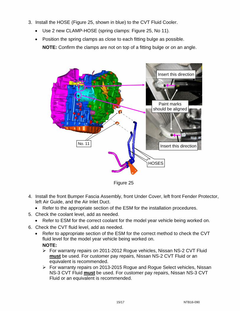
3. Install the HOSE (Figure 25, shown in blue) to the CVT Fluid Cooler.
Use 2 new CLAMP-HOSE (spring clamps: Figure 25, No 11).
Position the spring clamps as close to each fitting bulge as possible.
NOTE: Confirm the clamps are not on top of a fitting bulge or on an angle.
NO.15
Paint mark should be matched
Insert this direction
Insert this direction
Insert this direction
Paint marks
should be aligned
HOSE
Insert this direction
HOSES
No. 11
Figure 25
4. Install the front Bumper Fascia Assembly, front Under Cover, left front Fender Protector, left Air Guide, and the Air Inlet Duct.
Refer to the appropriate section of the ESM for the installation procedures.
5. Check the coolant level, add as needed.
Refer to ESM for the correct coolant for the model year vehicle being worked on.
6. Check the CVT fluid level, add as needed.
Refer to appropriate section of the ESM for the correct method to check the CVT fluid level for the model year vehicle being worked on.
NOTE: For warranty repairs on 2011-2012 Rogue vehicles, Nissan NS-2 CVT Fluid
must be used. For customer pay repairs, Nissan NS-2 CVT Fluid or an equivalent is recommended.
For warranty repairs on 2013-2015 Rogue and Rogue Select vehicles, Nissan NS-3 CVT Fluid must be used. For customer pay repairs, Nissan NS-3 CVT Fluid or an equivalent is recommended.
15/17 NTB16-090
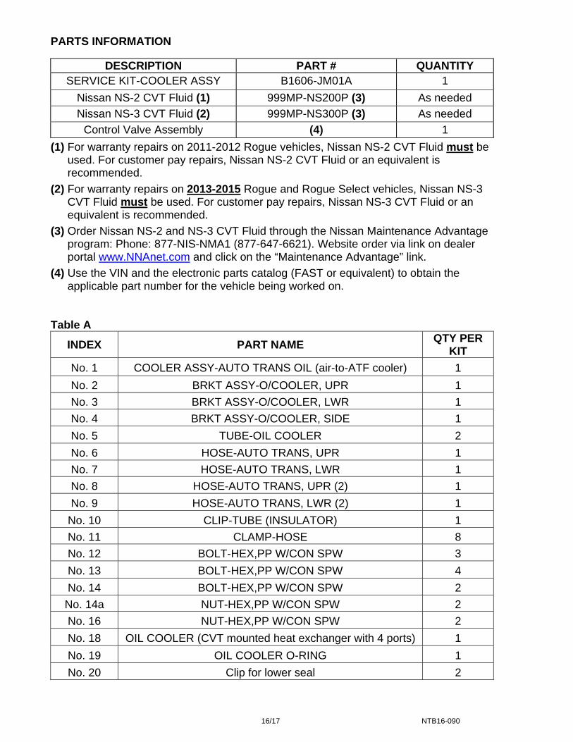
PARTS INFORMATION
DESCRIPTION PART # QUANTITY SERVICE KIT-COOLER ASSY B1606-JM01A 1
Nissan NS-2 CVT Fluid (1) 999MP-NS200P (3) As needed
Nissan NS-3 CVT Fluid (2) 999MP-NS300P (3) As needed
Control Valve Assembly (4) 1
(1) For warranty repairs on 2011-2012 Rogue vehicles, Nissan NS-2 CVT Fluid must be used. For customer pay repairs, Nissan NS-2 CVT Fluid or an equivalent is recommended.
(2) For warranty repairs on 2013-2015 Rogue and Rogue Select vehicles, Nissan NS-3 CVT Fluid must be used. For customer pay repairs, Nissan NS-3 CVT Fluid or an equivalent is recommended.
(3) Order Nissan NS-2 and NS-3 CVT Fluid through the Nissan Maintenance Advantage program: Phone: 877-NIS-NMA1 (877-647-6621). Website order via link on dealer portal www.NNAnet.com and click on the “Maintenance Advantage” link.
(4) Use the VIN and the electronic parts catalog (FAST or equivalent) to obtain the applicable part number for the vehicle being worked on.
Table A
INDEX PART NAME QTY PER
KIT
No. 1 COOLER ASSY-AUTO TRANS OIL (air-to-ATF cooler) 1
No. 2 BRKT ASSY-O/COOLER, UPR 1
No. 3 BRKT ASSY-O/COOLER, LWR 1
No. 4 BRKT ASSY-O/COOLER, SIDE 1
No. 5 TUBE-OIL COOLER 2
No. 6 HOSE-AUTO TRANS, UPR 1
No. 7 HOSE-AUTO TRANS, LWR 1
No. 8 HOSE-AUTO TRANS, UPR (2) 1
No. 9 HOSE-AUTO TRANS, LWR (2) 1
No. 10 CLIP-TUBE (INSULATOR) 1
No. 11 CLAMP-HOSE 8
No. 12 BOLT-HEX,PP W/CON SPW 3
No. 13 BOLT-HEX,PP W/CON SPW 4
No. 14 BOLT-HEX,PP W/CON SPW 2
No. 14a NUT-HEX,PP W/CON SPW 2
No. 16 NUT-HEX,PP W/CON SPW 2
No. 18 OIL COOLER (CVT mounted heat exchanger with 4 ports) 1
No. 19 OIL COOLER O-RING 1
No. 20 Clip for lower seal 2
16/17 NTB16-090
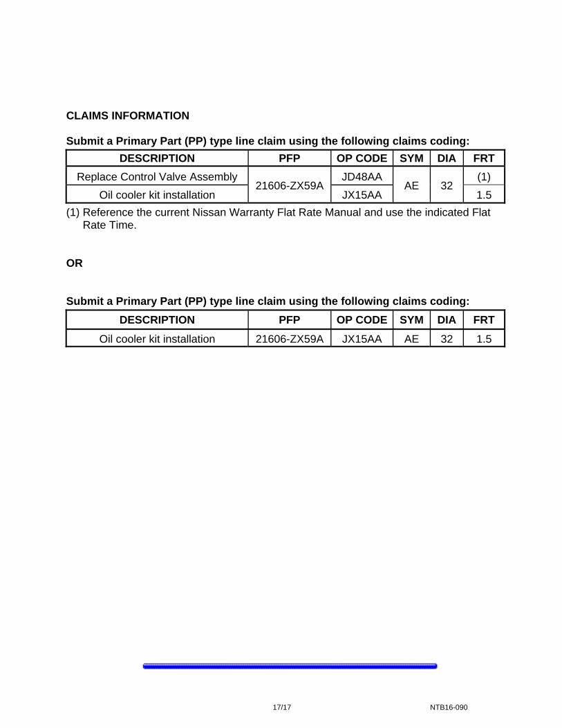
CLAIMS INFORMATION Submit a Primary Part (PP) type line claim using the following claims coding:
DESCRIPTION PFP OP CODE SYM DIA FRT
Replace Control Valve Assembly 21606-ZX59A
JD48AA AE 32
(1)
Oil cooler kit installation JX15AA 1.5
(1) Reference the current Nissan Warranty Flat Rate Manual and use the indicated Flat Rate Time.
OR Submit a Primary Part (PP) type line claim using the following claims coding:
DESCRIPTION PFP OP CODE SYM DIA FRT
Oil cooler kit installation 21606-ZX59A JX15AA AE 32 1.5
17/17 NTB16-090