Embed Size (px)
Citation preview

1/40
Classification: Reference: Date:
AT15-003f NTB15-037f August 10, 2018
VERSA SEDAN, VERSA NOTE, AND SENTRA; CVT VALVE BODY REPLACEMENT WITH CONFIRMED DTC
APPLIED VEHICLES: 2012 – 2017 Versa Sedan (N17) 2014 – 2017 Versa Note (E12) 2013 – 2017 Sentra (B17)
APPLIED TRANSMISSION: CVT (RE0F11A)
NOTE: Does not apply to 2017 Sentra equipped with MR16DDT turbo engine.
IF YOU CONFIRM
If one or more of the DTCs listed in the DTC Chart on page 2 are present in the Transmission Control Module (TCM).
And
No other DTCs are present other than what are listed in the DTC Chart.
ACTION
1. Go to Repair Overview on page 3 to determine which repairs to perform to the applied vehicle being worked on.
IMPORTANT: The purpose of “ACTION” (above) is to give you a quick idea of the work you will be performing. You MUST closely follow the entire Service Procedure as it contains information that is essential to successfully completing the repair.
Nissan Bulletins are intended for use by qualified technicians, not 'do-it-yourselfers'. Qualified technicians are properly trained individuals who have the equipment, tools, safety instruction, and know-how to do a job properly and safely. NOTE: If you believe that a described condition may apply to a particular vehicle, DO NOT assume that it does. See your Nissan dealer to determine if this applies to your vehicle.
This bulletin has been amended. A TCM P/N was added to 2015 Sentra in Table A. No other changes were made. Discard all previous versions of this bulletin.

2/40 NTB15-037f
DTC Chart
DTC CODE DTC/CIRCUIT DIAGNOSIS
P0711 TRANSMISSION FLUID TEMPERATURE SENSOR A
P0712 TRANSMISSION FLUID TEMPERATURE SENSOR A
P0713 TRANSMISSION FLUID TEMPERATURE SENSOR A
P0740 TORQUE CONVERTER
P0743 TORQUE CONVERTER
P0846 TRANSMISSION FLUID PRESSURE SEN/SW B
P0847 TRANSMISSION FLUID PRESSURE SEN/SW B
P0848 TRANSMISSION FLUID PRESSURE SEN/SW B
P0962 PRESSURE CONTROL SOLENOID A
P0963 PRESSURE CONTROL SOLENOID A
P0998 SHIFT SOLENOID F
P0999 SHIFT SOLENOID F
P0966 PRESSURE CONTROL SOLENOID B
P0967 PRESSURE CONTROL SOLENOID B
P099B SHIFT SOLENOID G
P099C SHIFT SOLENOID G

3/40 NTB15-037f
Repair Overview
Applied Vehicle has one or more DTCs in
the DTC Chart
All Applied Vehicles: Replace the control valve
assembly (valve body)
2012 Versa Sedan
2013-2017 Sentra 2014-2017 Versa NOTE 2013-2017 Versa Sedan
Reprogram the TCM
Erase Memory Data Conform CVTF Deteriortn Auxiliary gearbox clutch
point learning
Repairs in addition to valve body replacement:
END

4/40 NTB15-037f
SERVICE PROCEDURE
OIL PAN, CONTROL VALVE (Valve Body)
Exploded View
JSDIA6707GB
1. Transaxle assembly 2. O-ring 3. Control valve 4. Manual plate 5. Washer 6. O-ring
7. Strainer 8. Oil pan gasket 9. Magnet
10. Oil pan 11. Drain plug gasket 12. Drain plug 13. Overflow tube
: Apply petroleum jelly
: Always replace after every disassembly.
: Apply CVT fluid
: Nꞏm (kg-m, ft-lb)
: Nꞏm (kg-m, in-lb.) Valve Body: Removal and Installation
REMOVAL 1. Disconnect battery negative terminal.
2. Remove engine under cover.

5/40 NTB15-037f
3. Disconnect the CVT unit harness connector. 4. Remove the drain plug and overflow tube, and then drain the CVT fluid.
CAUTION: Use caution when looking into the drain hole as there is the risk of fluid entering the eye.
5. Remove the drain plug gasket from the drain plug. 6. Remove the oil pan mounting bolts ( ), and then remove
the oil pan and oil pan gasket.
: Vehicle front
7. Remove the magnets from the oil pan.
Clean magnets.
Clean CVT oil pan.
Reinstall magnets to the oil pan.
8. Remove the strainer bolts , and then remove the strainer from the control valve.
Discard the strainer. A new one will be used during assembly.
9. Remove the nut and washer , and then remove
manual plate . CAUTION: To remove nut, fix manual plate with flat-blade screwdriver (B).
10. Press the CVT unit harness connector into the transaxle case. CAUTION: Never damage the CVT unit harness connector. NOTE: Clean around the CVT unit harness connector to prevent foreign materials from entering into the transaxle case.
11. Remove the control valve bolts , and then remove the
control valve from the transaxle case. CAUTION: • Never drop the control valve and manual valve.

6/40 NTB15-037f
INSTALLATION 1. Install the control valve, and then tighten control valve bolts
to the specified torque. CAUTION: • Never pinch the harness between the control valve and the transaxle case. • Never drop the control valve and manual valve.
2. Install the manual plate and washer , and then tighten
nut to the specified torque. CAUTION: To tighten nut, fix manual plate with flat-blade screwdriver.
Reassembly Torque: 22.1 N•m (2.3 kg-m, 16 ft-lb)
3. Install the new strainer , and then tighten the strainer
bolts to the specified torque. 4. Install oil pan (with oil pan gasket) to transaxle case and
temporarily tighten oil pan bolts ( ).
CAUTION: Never reuse oil pan gasket.
: Vehicle front
5. Tighten the oil pan bolts to specification in the order shown.
: Vehicle front
6. Tighten the overflow tube to the specified torque. CAUTION: If it is not tightened to the specified torque, the tube may be damaged.
7. Connect the CVT unit harness connector. 8. Connect battery negative terminal. 9. Fill with CVT fluid from overflow tube to the specified level.
Refer to ESM for further information. 10. Install the drain plug and drain plug gasket to oil pan.
CAUTION: Never reuse drain plug gasket.
11. Reinstall engine under cover.
7/40 NTB15-037f
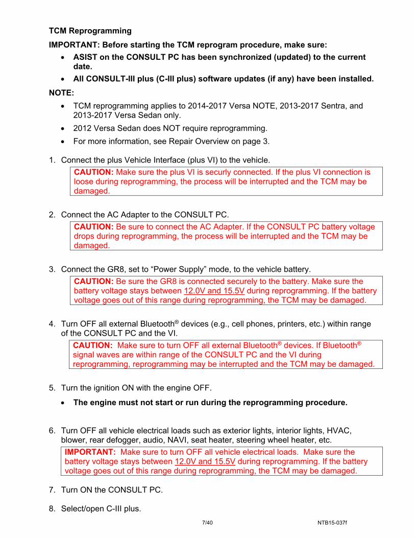
TCM Reprogramming
IMPORTANT: Before starting the TCM reprogram procedure, make sure:
ASIST on the CONSULT PC has been synchronized (updated) to the current date.
All CONSULT-III plus (C-III plus) software updates (if any) have been installed.
NOTE:
TCM reprogramming applies to 2014-2017 Versa NOTE, 2013-2017 Sentra, and 2013-2017 Versa Sedan only.
2012 Versa Sedan does NOT require reprogramming.
For more information, see Repair Overview on page 3. 1. Connect the plus Vehicle Interface (plus VI) to the vehicle.
CAUTION: Make sure the plus VI is securly connected. If the plus VI connection is loose during reprogramming, the process will be interrupted and the TCM may be damaged.
2. Connect the AC Adapter to the CONSULT PC.
CAUTION: Be sure to connect the AC Adapter. If the CONSULT PC battery voltage drops during reprogramming, the process will be interrupted and the TCM may be damaged.
3. Connect the GR8, set to “Power Supply” mode, to the vehicle battery.
CAUTION: Be sure the GR8 is connected securely to the battery. Make sure the battery voltage stays between 12.0V and 15.5V during reprogramming. If the battery voltage goes out of this range during reprogramming, the TCM may be damaged.
4. Turn OFF all external Bluetooth® devices (e.g., cell phones, printers, etc.) within range of the CONSULT PC and the VI.
CAUTION: Make sure to turn OFF all external Bluetooth® devices. If Bluetooth® signal waves are within range of the CONSULT PC and the VI during reprogramming, reprogramming may be interrupted and the TCM may be damaged.
5. Turn the ignition ON with the engine OFF.
The engine must not start or run during the reprogramming procedure.
6. Turn OFF all vehicle electrical loads such as exterior lights, interior lights, HVAC, blower, rear defogger, audio, NAVI, seat heater, steering wheel heater, etc.
IMPORTANT: Make sure to turn OFF all vehicle electrical loads. Make sure the battery voltage stays between 12.0V and 15.5V during reprogramming. If the battery voltage goes out of this range during reprogramming, the TCM may be damaged.
7. Turn ON the CONSULT PC. 8. Select/open C-III plus.

8/40 NTB15-037f
9. Wait for the plus VI to be recognized.
Serial number will display when the plus VI is recognized.
Figure 1
10. Select Re/programming, Configuration.
Figure 2
Step 9: plus VI is
recognized
Step 10

9/40 NTB15-037f
11. Use arrows (if needed) to view and read all precautions.
12. Check the box confirming the precautions have been read.
13. Select Next.
Figure 3
14. If the screen in Figure 4 displays, select Automatic Selection(VIN).
If the screen in Figure 4 does not display, skip to step 15.
Figure 4
Step 13
Step 12
Step 11
Example
Step 14

10/40 NTB15-037f
15. Make sure VIN or Chassis # matches the vehicle’s VIN.
16. If the correct VIN is displayed, select Confirm.
Figure 5 17. Select Confirm.
Figure 6
Step 15: Verify here
Step 17
Step 16
11/40 NTB15-037f
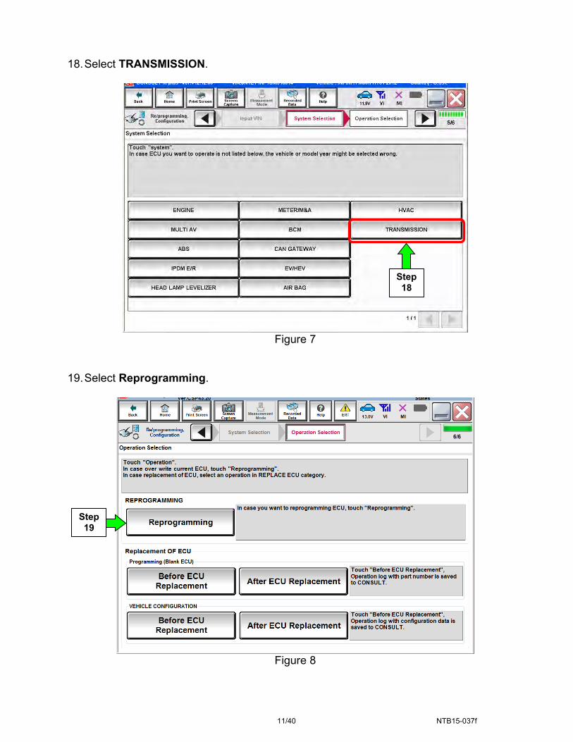
18. Select TRANSMISSION.
Figure 7
19. Select Reprogramming.
Figure 8
Step 19
Step 18

12/40 NTB15-037f
20. Follow the on-screen instructions; maintain the following conditions:
a. Ignition ON, with the engine OFF. b. Press the Brake. c. Press accelerator between ¼ and ½. d. Put shift selector in R.
21. Select Start.
Figure 9
22. When COMPLETED is displayed, select Next.
Figure 10
Step 21
Step 22

13/40 NTB15-037f
23. Operate the ignition per the on screen instructions.
Figure 11
24. When OK is displayed, select Next.
Figure 12
Progress display
Timer
Ignition status
Step 24

14/40 NTB15-037f
25. Move the shift selector to P, then select Next.
Figure 13
26. Operate the shift selector per the on-screen instructions.
a. Move the shift selector; P>R>N>D>P b. Confirm the center display meter indicates the correct selector position.
27. Select Next.
Figure 14
Step 25
Step 27
Step 26

15/40 NTB15-037f
Figure 15
30. Comparison results:
If there is a match, continue with the reprogramming procedure.
If there is not a match, reprogramming is not needed. Skip to ERASE MEMORY DATA on page 29.
Table A
MODEL MODEL YEAR CURRENT TCM PART NUMBER: 31036 -
Sentra
2013 3SG0A, 3SG0B, 3SG0C, 3SG9B, 3SG9C, 3SR0A, 3SR0B, 3SR0C, 3SR9B, 3SR9C
2014 9AM2A, 9AM2B, 9AM2C, 9AM9B, 9AM9D, 9AM9E
2015 4AT0A, 4AT0B, 4AT0C, 4AT0D, 4AT9A, 4AT9D, 4AT8E, 4AT9E
2016 4AF6A, 4AF6B, 4AF9D
2017 4FY0A, 4FY0B, 4FY0C
Versa Sedan
2013 9KB1B, 9KB1C, 9KB1D, 9KB9E, 9KJ9E
2014 3BE0A, 3BE0B, 3BE9A, 3BE9C
2015 9KE0A, 9KE0B, 9KE0C, 9KE9C, 9KE9E
2016 9KN0A, 9KN0B, 9KN0C, 9KN8D, 9KN8E
2017 9KN2A, 9KN2B, 9KN2C
Versa NOTE
2014 3VB2A, 3VB2B, 3VB2C, 3VB8C, 3VB9D
2015 3VB6A, 3VB9A, 3VB9B, 3VB9C, 3VB9E, 3WC9D
2016 3VB4A, 3VB4B, 3VB4C, 3VB4D, 3VB7A, 3WC9E
2017 9ME0A, 9ME0B, 9ME0C 31. Select Save.
Step 28
28. Find the TCM Part Number
(see Figure 15) and write it on the repair order.
NOTE: This is the current Part Number (P/N).
29. Compare the P/N you wrote down to the numbers in the Current TCM Part Number column in Table A below.
Step 31
16/40 NTB15-037f
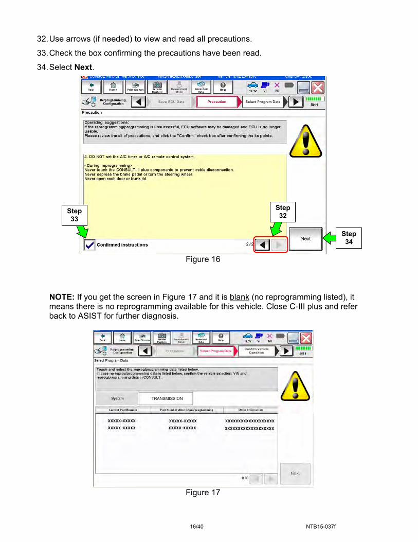
32. Use arrows (if needed) to view and read all precautions.
33. Check the box confirming the precautions have been read.
34. Select Next.
Figure 16
NOTE: If you get the screen in Figure 17 and it is blank (no reprogramming listed), it means there is no reprogramming available for this vehicle. Close C-III plus and refer back to ASIST for further diagnosis.
Figure 17
Step 34
Step 33
Step 32
TRANSMISSION

17/40 NTB15-037f
35. Read the Current Part Number and Part Number After Reprogramming. They
should be different.
36. Select Next.
Figure 17a
Step 35
These numbers should be different
Step 36

18/40 NTB15-037f
37. Make sure OK is highlighted green (battery voltage must be between 12.0 and 15.5 Volts).
38. Select Next.
IMPORTANT: Battery voltage must stay between 12.0 and 15.5 Volts during reprogramming or TCM reprogramming may be interrupted and TCM may be damaged.
Figure 18
39. Make sure OK is highlighted green for all Judgements then select Start.
Figure 19
Monitor battery voltage here
Step 38
Step 37
Step 39
Monitor battery voltage here
EXAMPLE

19/40 NTB15-037f
40. Select USA/CANADA Dealers.
41. Select OK.
Figure 20
NOTE:
The above screen may not display if the CONSULT PC has remained ON since the last reprogramming.
If the CONSULT PC is not connected to the Internet, the screen in Figure 21 will display.
Figure 21
Step 41
Step40

20/40 NTB15-037f
42. Enter Username and Password.
Before reprogramming will start, you will be required to enter your User Name and Password.
The CONSULT PC must be connected to the Internet (Wi-Fi or cable).
If you do not know your User Name and Password, contact your Service Manager.
43. Select Submit.
There will be a short pause while the username and password are authenticated.
Once authentication completes, TCM reprogramming will automatically begin
and the screen in Figure 23 on the next page will be displayed.
Figure 22
Step 42
Step 43

21/40 NTB15-037f
44. Wait for both progress bars to complete.
Figure 23
45. When the screen in Figure 24 displays, the reprogramming is complete.
NOTE: If the screen in Figure 24 does not display (which indicates reprogramming did not complete), refer to the information on the next page.
46. Disconnect the battery charger (GR8) from the vehicle.
47. Select Next.
Figure 24
NOTE: Additional steps/operations are required before C-III plus will provide the final reprogramming confirmation report. Continue with the reprogramming procedure on page 23.
Step 47
Step 44

22/40 NTB15-037f
If reprogramming does not complete and the “!?” symbol displays as shown in Figure 25:
Figure 25
If reprogramming does not complete and the “X” symbol displays as shown in Figure 26:
Figure 26
Check battery voltage (12.0 – 15.5V).
Ignition ON, engine OFF.
External Bluetooth® devices are OFF.
All electrical loads are OFF.
Select Retry and follow the on screen instructions.
NOTE: Retry may not go through on first attempt and can be selected more than once.
Do not disconnect the plus VI or shut down C-III plus if reprogramming does not complete.
Check battery voltage (12.0 – 15.5V).
CONSULT A/C adapter is plugged in.
Ignition ON, engine OFF.
Transmission in Park.
All C-III plus / plus VI cables are securely connected.
All C-III plus updates are installed.
Select Home, and then restart the reprogram procedure from the beginning.

23/40 NTB15-037f
48. Confirm the Transmission Fluid temperature judgment is OK, then select Next.
If the judgment is NG, drive the vehicle to warm the transmission until the judgment changes to OK.
Figure 27
Step 48

24/40 NTB15-037f
Figure 28
Figure 29
Step 50
Step 52
49. Follow the on-screen instructions; maintain the following conditions:
a. Parking brake set.
b. Ignition ON, with the engine OFF.
c. Press the Brake.
d. Press accelerator between ¼ and ½.
e. Put shift selector in R.
50. Select Erase DTC.
51. Follow the on-screen
instructions; maintain the following conditions:
a. Parking brake set.
b. Ignition ON, with the engine OFF.
c. Fully depress the accelerator.
d. Put shift selector in R.
52. Select Start.

25/40 NTB15-037f
53. When COMPLETED is displayed, select Next.
Figure 30
54. Operate the ignition per the on-screen instructions.
Figure 31
Progress display
Timer
Ignition status
Step 53

26/40 NTB15-037f
55. When OK is displayed, select Next.
Figure 32
56. Operate the shift selector per the on-screen instructions.
a. Move the shift selector to P; then move P>R>N>D>P b. Confirm the center display meter indicates the correct selector position.
57. Select Next.
Figure 33
Step 55
Step 57
Step 56
27/40 NTB15-037f
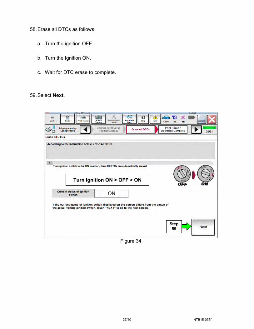
58. Erase all DTCs as follows:
a. Turn the ignition OFF.
b. Turn the Ignition ON.
c. Wait for DTC erase to complete.
59. Select Next.
Figure 34
ON
Turn ignition ON > OFF > ON
Step 59

28/40 NTB15-037f
60. Verify the before and after part numbers are different.
61. Print a copy of this screen (Figure 35) and attach it to the repair order.
62. Select Confirm.
Figure 35
NOTE: If you cannot print the above screen:
a. Select Screen Capture. b. Name the file. c. Save the file in My Documents.
A copy of the screen is now saved in the CONSULT PC. It can be retrieved and printed at a later time.
Step 62
Step 60
Step 61

29/40 NTB15-037f
ERASE MEMORY DATA
NOTE: This procedure is for all Applied Vehicles.
63. Navigate C-III plus to the screen shown in Figure 36.
Diagnosis (All Systems) > TRANSMISSION > Work support
64. Select ERASE MEMORY DATA.
65. Select Start.
Figure 36
Step 64 Step
65
30/40 NTB15-037f
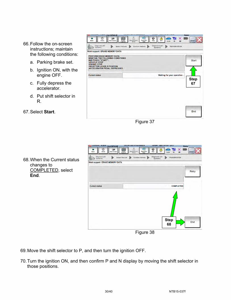
Figure 37
Figure 38
69. Move the shift selector to P, and then turn the ignition OFF. 70. Turn the ignition ON, and then confirm P and N display by moving the shift selector in
those positions.
Step 67
66. Follow the on-screen
instructions; maintain the following conditions:
a. Parking brake set.
b. Ignition ON, with the engine OFF.
c. Fully depress the accelerator.
d. Put shift selector in R.
67. Select Start.
68. When the Current status
changes to COMPLETED, select End.
Step 68

31/40 NTB15-037f
CONFORM CVTF DETERIORTN
NOTE: This procedure is for all Applied Vehicles.
71. Navigate C-III plus to the screen shown in Figure 39.
Diagnosis (All Systems) > TRANSMISSION > Work support
72. Select CONFORM CVTF DETERIORTN.
73. Select Start.
Figure 39
74. Select Start.
Figure 40
Step 73
Step 74
Step 72

32/40 NTB15-037f
75. Select Clear.
Figure 41
76. Select Yes.
Figure 42
Step 75
Step 76

33/40 NTB15-037f
77. When CVFT DETERIORATION DATE changes to “0”, select End.
Figure 43
78. Start the engine. 79. Set the parking brake. 80. Turn OFF the A/C. 81. Bring the engine to normal operating temperature range. 82. Confirm the CVT fluid temperature is over 122°F (50°C).
0
Step 77

34/40 NTB15-037f
Auxiliary gearbox clutch point learning
NOTE: This procedure is for all Applied Vehicles. 83. Navigate C-III plus to the screen shown in Figure 44.
Diagnosis (All Systems) > TRANSMISSION > Work support 84. Select Auxiliary gearbox clutch point learning.
Or
If this feature is not available in the vehicle that is being repaired, skip to Manual Auxiliary gearbox clutch point learning on page 38.
85. Select Start.
Figure 44
Step 84
Step 85

35/40 NTB15-037f
86. Follow the on-screen instructions in Figure 45, and then select Start.
Figure 45
87. With the brake pedal still applied, shift the CVT selector lever into the D position.
Figure 46 (below) will be displayed after shifting into D position.
NOTE: The Current status will show EXECUTING (Figure 46), but until the vehicle is shifted into the D position, Auxiliary gearbox clutch point learning will not begin.
Figure 46
Step 87
Step 86

36/40 NTB15-037f
88. Continue to depress the brake pedal until the Current status shows “Completed” as shown in Figure 48 at the bottom of this page.
NOTE: This may take several minutes to complete.
Figure 47
89. When Completed is displayed, select End.
Figure 48
90. Shift the vehicle into “P”, turn ignition OFF and release the brake pedal. 91. Perform Auxiliary Gearbox Clutch Point Learning (steps 83 to 89) one additional time
(a total of two times).
Step 89

37/40 NTB15-037f
Erase DTCs
NOTE: This procedure is for all Applied Vehicles.
92. Use C-III plus to erase any transmission DTCs that may have stored. 93. Turn OFF C-III plus.
94. Disconnect C-III plus and the plus VI from the vehicle.
95. Verify the CVT operates normally and no abnormal noises are heard during a test drive.

38/40 NTB15-037f
MANUAL AUXILIARY GEARBOX CLUTCH POINT LEARNING
CAUTION: If clutch touch point learning is not performed, you may feel shift shock when the auxiliary transmission shifts.
NOTE: This manual procedure is only needed if the auto procedure is not available in C-III plus.
a. Start the engine and warm up the CVT fluid to 50°C (122°F).
NOTE: Confirm the CVT fluid temperature by “FLUID TEMP” in “Data Monitor”.
b. Turn the air conditioner OFF.
c. Shift the CVT selector lever to the P position, turn the ignition OFF and then wait for 5 seconds.
d. Start the engine and allow it to idle for 5 seconds.
e. Turn the ignition OFF and then wait for 30 seconds.
f. Perform Step “e” to Step “f” two more times (Total: Three times).
g. Start the engine.
h. Allow engine to idle for 30 seconds.
i. Shift the CVT selector lever to D position.
j. Accelerate the vehicle from 0 km/h (0 MPH) to 65 km/h (40 MPH) at low throttle (0.5/8 – 1/8).
k. Decelerate the vehicle to 30 km/h (18 MPH) or less without using brakes.
l. Stop the vehicle and shift the selector lever to P position.
m. Turn the ignition OFF and wait for 5 seconds or more.
n. Restart the engine.
o. Perform Step “j” to Step “o” four times (Total: Five times).
p. Shift the selector lever to D position.
q. Accelerate the vehicle from 0 km/h (0 MPH) to 45 km/h (28 MPH) at low throttle (0.5/8 – 1/8).
r. Stop the vehicle and shift the selector lever to P position.
s. Turn the ignition OFF for 5 seconds or more and then restart the engine.
t. Perform Steps “q” to Step “t” four times (Total: Five times).
u. Drive the vehicle and check that no shock occurs while shifting gears.

39/40 NTB15-037f
PARTS INFORMATION
All Vehicles
DESCRIPTION PART # QUANTITY
GASKET (CVT drain plug) 11026-JA00A 1NS-3 CVT Fluid
999MP-NS300P (1) as needed (All vehicles listed below except 2012 MY Versa Sedan)
NS-2 CVT Fluid (2012 MY Versa Sedan only) 999MP-NS200P (1) as needed
(1) NS-2 and NS-3 CVT Fluids can be ordered through the Nissan Maintenance Advantage program: Phone: 877-NIS-NMA1 (877-647-6621). Website order via link on dealer portal www.NNAnet.com and click on the “Maintenance Advantage” link.
Versa Sedan MY 2013-2017 and Versa NOTE MY 2014-2017 DESCRIPTION PART # QUANTITY
KIT-CONTROL VALVE 3170E-X428B 1
Kit Includes
VALVE ASSY - CONTROL - - 1
GASKET - OIL PAN - - 1
STRAINER ASSY-OIL - - 1
Versa Sedan MY 2012
DESCRIPTION PART # QUANTITY VALVE ASSY - CONTROL 31705-3JX8A 1
STRAINER ASSY-OIL 31728-3JX0B 1 GASKET - OIL PAN 31397-3JX0A 1
Sentra MY 2013-2017 DESCRIPTION PART # QUANTITY
KIT-CONTROL VALVE 3170E-X428C 1Kit Includes
VALVE ASSY - CONTROL - - 1GASKET - OIL PAN - - 1
STRAINER ASSY-OIL - - 1

40/40 NTB15-037f
CLAIMS INFORMATION
Submit a Primary Part (PP) type line claim using the following claims coding:
OPERATION PFP OP CODE SYM DIAG FRT
Replace Control Valve (1) JD48AA HC 32 (2)
(1) Refer to the Electronic Parts Catalog (FAST) and use the applicable Control Valve Assembly Part Number (31705-*****) as the Primary Failed Part.
(2) Reference the current Nissan Warranty Flat Rate Manual and use the indicated flat rate time.
And if needed on the same line
OPERATION OP CODE FRT
Reprogram TCM JE99AA (1)
(1) Reference the current Nissan Warranty Flat Rate Manual and use the indicated flat rate time.