Embed Size (px)
Citation preview


3
CONTENTS
LOW-COST LONG-HAUL PTP MICROWAVE RADIO MIC-RL400P .............................4
COST-EFFECTIVE MICROWAVE BACKHAUL RADIO MIC-RLP ..............................6
HYBRID TDM/IP MICROWAVE RADIO MIC-RLPM .........................................8
COST-EFFECTIVE FLEXIBLE PTP MICROWAVE RADIO MIC-RL5VRM ......................10
FULL OUTDOOR ETHERNET RADIO MIC-RLPE ..........................................12
HIGH-SPEED FLEXIBLE PTP MICROWAVE RADIO MIC-RLP+ ............................14
WIRELRSS BROADBAND SYSTEM WIMIC-6000 ........................................18
COGNITIVE BROADBAND SYSTEM MIC-RL500CR .......................................22NEW!
4
TELE
COM
MU
NIC
ATIO
N E
QU
IPM
ENT
LOW
-CO
ST L
ON
G-H
AU
L P
TP M
ICR
OW
AVE
RA
DIO
MIC
-RL4
00P
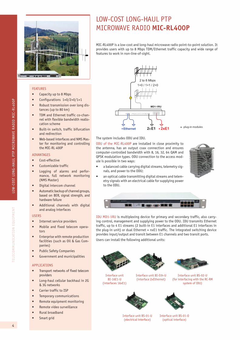
LOW-COST LONG-HAUL PTPMICROWAVE RADIO MIC-RL400P
MIC-RL400P is a low-cost and long-haul microwave radio point-to-point solution. It provides users with up to 8 Mbps TDM/Ethernet traffic capacity and wide range of features to work in non-line-of-sight.
MD1-1RU
2 to 8 Mbps1+0 / 1+1 / 2+0
2хE1 � 2xE1
..
�Ethernet ��plug-in modules
The system includes ODU and IDU.
ODU of the MIC-RL400P are installed in close proximity to the antenna, has an output coax connection and ensures computer-controlled bandwidth with 8, 16, 32, 64 QAM and QPSK modulation types. ODU connection to the access mod-ule is possible in two ways:
�� a balanced cable carrying digital streams, telemetry sig-nals, and power to the ODU;
�� an optical cable transmitting digital streams and telem-etry signals with an electrical cable for supplying power to the ODU.
Interface unit BI-16E1-U
(interfaces 16xE1)
Interface unit BI-Eth-U(interface 2xEthernet)
Interface unit BS-02-U(for interfacing with the RC-RM
system of IDU)
Interface unit BS-01-U(electrical interface)
Interface unit BS-01-O(optical interface)
IDU MD1-1RU is multiplexing device for primary and secondary traffic, also carry-ing control, management and supplying power to the ODU. IDU transmits Ethernet traffic, up to 4 E1 streams (2 built-in E1 interfaces and additional E1 interfaces in the plug-in unit) or dual Ethernet + nxE1 traffic. The integrated switching device provides input/output and transit between E1 channels and two transit ports.
Users can install the following additional units:
FEATURES
�� Capacity up to 8 Mbps
�� Configurations 1+0/2+0/1+1
�� Robust transmission over long dis-tances (up to 80 km)
�� TDM and Ethernet traffic co-chan-nel with flexible bandwidth reallo-cation scheme
�� Built-in switch, traffic bifurcation and redirection
�� Web-based interfaces and NMS Mas-ter for monitoring and controlling the MIC-RL 400P
ADVANTAGES
�� Cost-effective
�� Customizable traffic
�� Logging of alarms and perfor-mance, full network monitoring (NMS Master)
�� Digital intercom channel
�� Automatic backup of channel groups, based on BER, signal strength, and hardware failure
�� Additional channels with digital and analog interfaces
APPLICATIONS
�� Transport networks of fixed telecom providers
�� Long-haul cellular backhaul in 2G & 3G networks
�� Carrier traffic to ISP
�� Temporary communications
�� Remote equipment monitoring
�� Remote video surveillance
�� Rural broadband
�� Smart grid
USERS
�� Internet service providers
�� Mobile and fixed telecom opera-tors
�� Enterprise with remote production facilities (such as Oil & Gas Com-panies)
�� Public Safety Companies
�� Government and municipalities
5
TELE
COM
MU
NIC
ATIO
N E
QU
IPM
ENT
LOW
-CO
ST L
ON
G-H
AU
L P
TP M
ICR
OW
AVE
RA
DIO
MIC
-RL4
00P
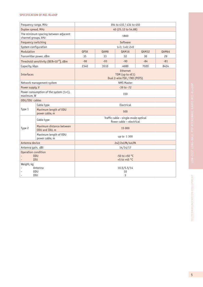
SPECIFICATION OF MIC-RL400P
Frequency range, MHz 394 to 410 / 434 to 450
Duplex spread, MHz 40 (25.12 to 54.88)
The minimum spacing between adjacent channel groups, kHz
1860
Frequency switching Software
System configuration 1+1; 1+0; 2+0
Modulation QPSK QAM8 QAM16 QAM32 QAM64
Transmitter power, dBm 35 33 32 30 29
Threshold sensitivity (BER=10-6), dBm -96 -93 -90 -84 -81
Capacity, kbps 2340 3510 4680 7020 8424
InterfacesEthernet
TDM (up to 4E1)Dual 2-wire FSX / FXO (POTS)
Network management system NMS Master
Power supply, V -39 to -72
Power consumption of the system (1+1), maximum, W
150
ODU/IDU cables
Type 1Cable type Electrical
Maximum length of ODU power cable, m
500
Type 2
Cable typeTraffic cable - single-mode optical
Power cable – electrical
Maximum distance between ODU and IDU, m
15 000
Maximum length of ODU power cable, m
up to 1 300
Antenna device 2xZ/2xLPA/4xLPA
Antenna gain, dBi 14/14/17
Operation condition - ODU- IDU
-50 to +50 °C+5 to +45 °C
Weight, kg- Antenna- ODU- IDU
10.5/5.5/14103
6
TELE
COM
MU
NIC
ATIO
N E
QU
IPM
ENT
COST
-EFF
ECTI
VE M
ICR
OW
AVE
BA
CKH
AU
L R
AD
IO M
IC-R
LP
COST-EFFECTIVE MICROWAVEBACKHAUL RADIO MIC-RLP
FEATURES
�� Hybrid TDM and Ethernet traffic co-channel with flexible bandwidth reallocation scheme
�� Configurations 1+0/2+0/1+1
�� Built-in switch, traffic bifurcation and redirection
�� Valid payload up to 18 E1@28MHz with QPSK modulation
�� Web-based interfaces and MMS Master for monitoring and control-ling the MIC-RLP
ADVANTAGES
�� Automatic backup of channel groups, based on BER, signal strength, and hardware failure
�� Additional channels with digital and analog interfaces (plug-in module MD-E1)
�� Digital intercom channel
�� Logging of alarms and perfor-mance, full network monitoring (NMS Master)
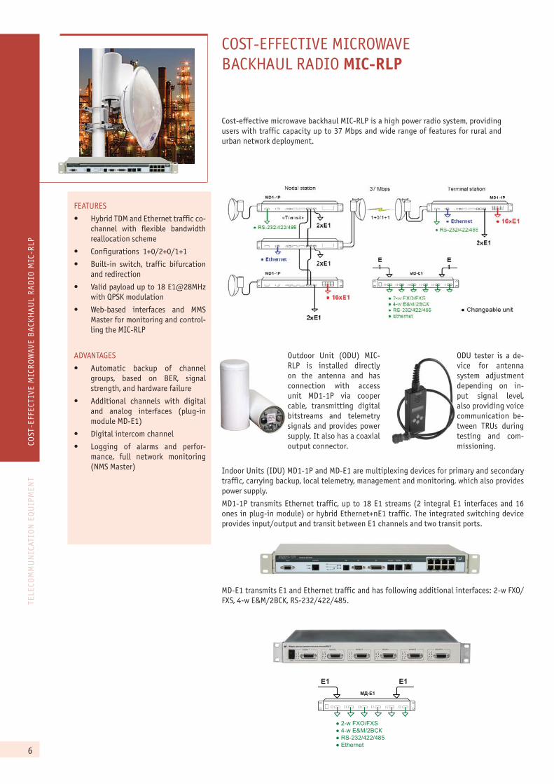
Cost-effective microwave backhaul MIC-RLP is a high power radio system, providing users with traffic capacity up to 37 Mbps and wide range of features for rural and urban network deployment.
���6�
�� ��
- �; <=>�<=8- 9; �?@��� �- 78����9���9!:- ��������
Outdoor Unit (ODU) MIC-RLP is installed directly on the antenna and has connection with access unit MD1-1P via cooper cable, transmitting digital bitstreams and telemetry signals and provides power supply. It also has a coaxial output connector.
ODU tester is a de-vice for antenna system adjustment depending on in-put signal level, also providing voice communication be-tween TRUs during testing and com-missioning.
Indoor Units (IDU) MD1-1P and MD-E1 are multiplexing devices for primary and secondary traffic, carrying backup, local telemetry, management and monitoring, which also provides power supply.
MD1-1P transmits Ethernet traffic, up to 18 E1 streams (2 integral E1 interfaces and 16 ones in plug-in module) or hybrid Ethernet+nE1 traffic. The integrated switching device provides input/output and transit between E1 channels and two transit ports.
MD-E1 transmits E1 and Ethernet traffic and has following additional interfaces: 2-w FXO/FXS, 4-w E&M/2BCK, RS-232/422/485.
7
TELE
COM
MU
NIC
ATIO
N E
QU
IPM
ENT
COST
-EFF
ECTI
VE M
ICR
OW
AVE
BA
CKH
AU
L R
AD
IO M
IC-R
LP
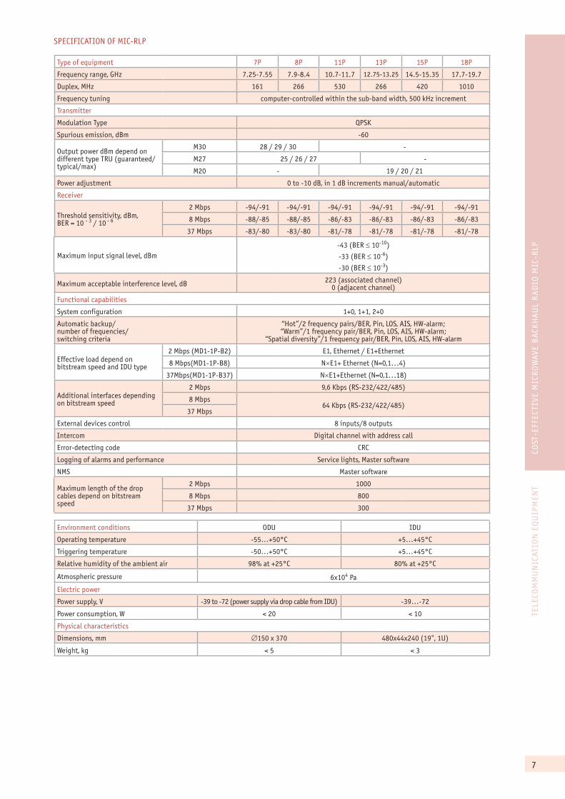
SPECIFICATION OF MIC-RLP
Type of equipment 7P 8P 11P 13P 15P 18P
Frequency range, GHz 7.25-7.55 7.9-8.4 10.7-11.7 12.75-13.25 14.5-15.35 17.7-19.7
Duplex, MHz 161 266 530 266 420 1010
Frequency tuning computer-controlled within the sub-band width, 500 kHz increment
Transmitter
Modulation Type QPSK
Spurious emission, dBm -60
Output power dBm depend on different type TRU (guaranteed/typical/max)
Ì30 28 / 29 / 30 -
Ì27 25 / 26 / 27 -
Ì20 - 19 / 20 / 21
Power adjustment 0 to -10 dB, in 1 dB increments manual/automatic
Receiver
Threshold sensitivity, dBm, BER = 10 - 3 / 10 - 6
2 Mbps -94/-91 -94/-91 -94/-91 -94/-91 -94/-91 -94/-91
8 Mbps -88/-85 -88/-85 -86/-83 -86/-83 -86/-83 -86/-83
37 Mbps -83/-80 -83/-80 -81/-78 -81/-78 -81/-78 -81/-78
Maximum input signal level, dBm-43 (BER � 10-10)
-33 (BER � 10-6)
-30 (BER � 10-3)
Maximum acceptable interference level, dB 223 (associated channel)0 (adjacent channel)
Functional capabilities
System configuration 1+0, 1+1, 2+0
Automatic backup/number of frequencies/switching criteria
“Hot”/2 frequency pairs/BER, Pin, LOS, AIS, HW-alarm;“Warm”/1 frequency pair/BER, Pin, LOS, AIS, HW-alarm;
“Spatial diversity”/1 frequency pair/BER, Pin, LOS, AIS, HW-alarm
Effective load depend on bitstream speed and IDU type
2 Mbps (MD1-1P-B2) E1, Ethernet / E1+Ethernet
8 Mbps(MD1-1P-B8) N�E1+ Ethernet (N=0,1...4)
37Mbps(MD1-1P-B37) N�E1+Ethernet (N=0,1...18)
Additional interfaces depending on bitstream speed
2 Mbps 9,6 Kbps (RS-232/422/485)
8 Mbps64 Kbps (RS-232/422/485)
37 Mbps
External devices control 8 inputs/8 outputs
Intercom Digital channel with address call
Error-detecting code CRC
Logging of alarms and performance Service lights, Master software
NMS Master software
Maximum length of the drop cables depend on bitstream speed
2 Mbps 1000
8 Mbps 800
37 Mbps 300
Environment conditions ODU IDU
Operating temperature -55…+50°Ñ +5…+45°Ñ
Triggering temperature -50…+50°Ñ +5…+45°Ñ
Relative humidity of the ambient air 98% at +25°Ñ 80% at +25°Ñ
Atmospheric pressure 6õ104 Pa
Electric power
Power supply, V -39 to -72 (power supply via drop cable from IDU) -39…-72
Power consumption, W < 20 < 10
Physical characteristics
Dimensions, mm �150 õ 370 480õ44õ240 (19", 1U)
Weight, kg < 5 < 3

8
TELE
COM
MU
NIC
ATIO
N E
QU
IPM
ENT
HYB
RID
TD
M/I
P M
ICR
OW
AVE
RA
DIO
MIC
-RLP
M
HYBRID TDM/IP MICROWAVE RADIO MIC-RLPM
MIC-RLPM – is effective wireless solution for hybrid TDM/IP traffic transmission for cellular and fixed providers, corporate and government customers. This provides up to 150 Mbps (in 2+0 mode) traffic capacity in frequency range from 5 to 15 GHz.
Transmit-receive units (TRU) MIC-RLPM are installed directly on the antenna and has digital multimedia modem providing computer-controlled bandwidth and 16QAM/QPSK modulation types. It has a coaxial output connector in the 7 to 18 GHz range and a waveguide flange in the 23 to 40 GHz range. The TRU transmits the digital bitstreams and telemetry signals to IDU via single optical cable. It also has single electrical cable, which provides power supply, and an output coax connection.
IDU MD1-1RU is multiplexing device for primary and secondary traffic, also carrying backup, local telemetry, management and monitoring. It provides power supply, transmitting Ethernet traffic, up to 18 E1 streams (2 integral E1 interfaces and 16 ones in plug-in module) or hybrid Ethernet+nE1 traffic transmitting. The integrated switching device provides input/output and transit between E1 channels and two transit ports.
Users can install the following additional units:
FEATURES
�� Flexible capacity 5 to 78 Mbps @28 MHz
�� Configurations 1+0/2+0/1+1;
�� TDM and Ethernet traffic co-chan-nel with flexible changing of ca-pacity
�� Built-in switch
�� Web-based interfaces and MMS Master for monitoring and control-ling the MIC-RLPM
ADVANTAGES
�� Cost-effective
�� Automatic backup of channel groups
�� Additional channels with digital and analog interfaces (plug-in module MD-E1)
�� Digital intercom channel
�� Logging of alarms and perfor-mance, full network management and monitoring (NMS Master)
Interface unit BI-16E1-U
(interfaces 16xE1)
Interface unit BI-Eth-U(interface 2xEthernet)
Interface unit BS-02-U(for interfacing with the RC-RM
system of IDU)
Interface unit BS-01-O(optical interface)
2�E1
2�E1
2�E1
2�E1
«Transit»
78.6 Mbps
1+0/1+1
Nodal station Terminal station
- Changeable unit
��Ethernet
MD1-1�
MD-�1
E1
E1
MD1-1�
MD1-1�
- RS-232/422/485
��Ethernet
- 2-w FXO/FXS- 4-w E&M/2� �- RS-232/422/485- Ethernet
- RS-232/422/485
��16xE1
��16xE1
9
TELE
COM
MU
NIC
ATIO
N E
QU
IPM
ENT
HYB
RID
TD
M/I
P M
ICR
OW
AVE
RA
DIO
MIC
-RLP
M
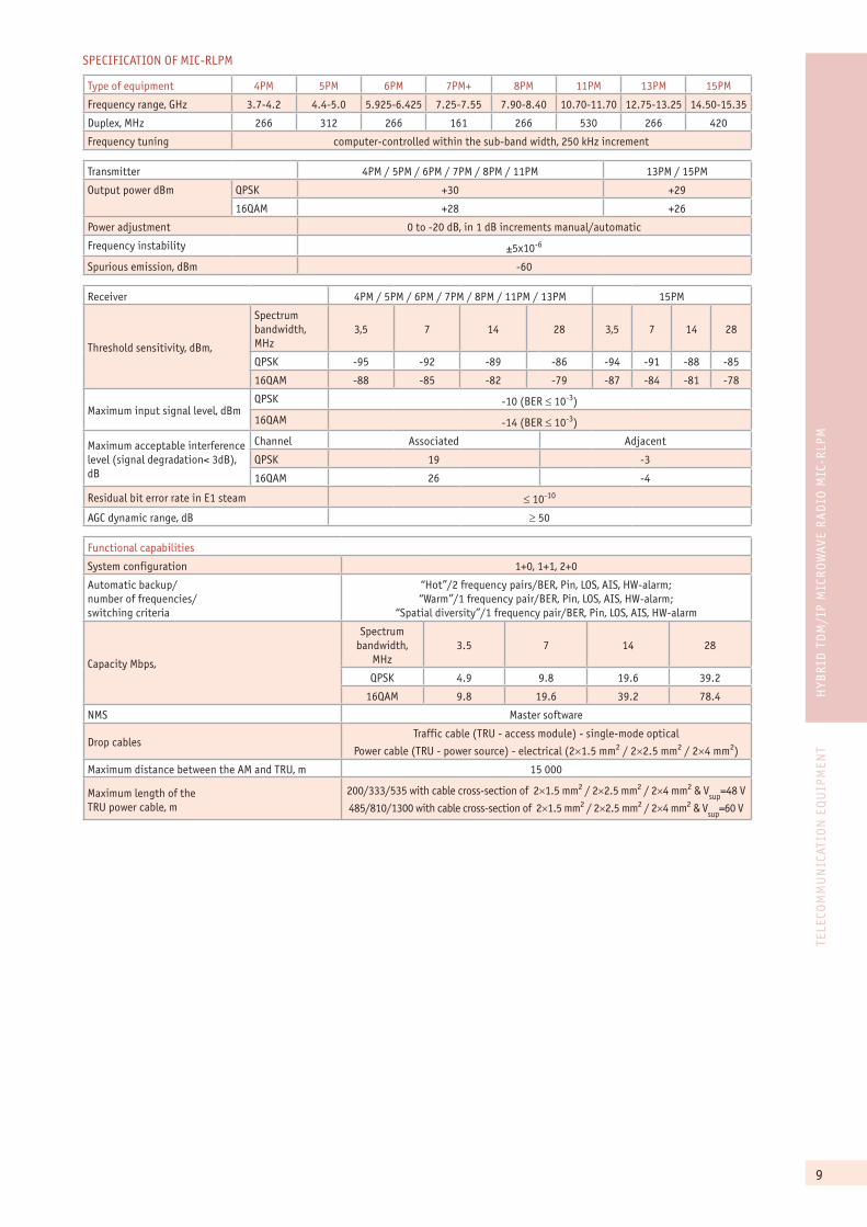
SPECIFICATION OF MIC-RLPM
Type of equipment 4ÐÌ 5ÐÌ 6ÐÌ 7ÐÌ+ 8ÐÌ 11ÐÌ 13ÐÌ 15ÐÌ
Frequency range, GHz 3.7-4.2 4.4-5.0 5.925-6.425 7.25-7.55 7.90-8.40 10.70-11.70 12.75-13.25 14.50-15.35
Duplex, MHz 266 312 266 161 266 530 266 420
Frequency tuning computer-controlled within the sub-band width, 250 kHz increment
Transmitter 4ÐÌ / 5ÐÌ / 6ÐÌ / 7ÐÌ / 8ÐÌ / 11ÐÌ 13ÐÌ / 15ÐÌ
Output power dBm QPSK +30 +29
16QAM +28 +26
Power adjustment 0 to -20 dB, in 1 dB increments manual/automatic
Frequency instability ±5õ10-6
Spurious emission, dBm -60
Receiver 4ÐÌ / 5ÐÌ / 6ÐÌ / 7ÐÌ / 8ÐÌ / 11ÐÌ / 13ÐÌ 15ÐÌ
Threshold sensitivity, dBm,
Spectrum bandwidth, MHz
3,5 7 14 28 3,5 7 14 28
QPSK -95 -92 -89 -86 -94 -91 -88 -85
16QAM -88 -85 -82 -79 -87 -84 -81 -78
Maximum input signal level, dBmQPSK -10 (BER � 10-3)
16QAM -14 (BER � 10-3)
Maximum acceptable interference level (signal degradation< 3dB), dB
Channel Associated Adjacent
QPSK 19 -3
16QAM 26 -4
Residual bit error rate in E1 steam � 10-10
AGC dynamic range, dB � 50
Functional capabilities
System configuration 1+0, 1+1, 2+0
Automatic backup/number of frequencies/switching criteria
“Hot”/2 frequency pairs/BER, Pin, LOS, AIS, HW-alarm;“Warm”/1 frequency pair/BER, Pin, LOS, AIS, HW-alarm;
“Spatial diversity”/1 frequency pair/BER, Pin, LOS, AIS, HW-alarm
Capacity Mbps,
Spectrum bandwidth,
MHz3.5 7 14 28
QPSK 4.9 9.8 19.6 39.2
16QAM 9.8 19.6 39.2 78.4
NMS Master software
Drop cablesTraffic cable (TRU - access module) - single-mode optical
Power cable (TRU - power source) - electrical (2�1.5 mm2 / 2�2.5 mm2 / 2�4 mm2)
Maximum distance between the AM and TRU, m 15 000
Maximum length of theTRU power cable, m
200/333/535 with cable cross-section of 2�1.5 mm2 / 2�2.5 mm2 / 2�4 mm2 & Vsup
=48 V
485/810/1300 with cable cross-section of 2�1.5 mm2 / 2�2.5 mm2 / 2�4 mm2 & Vsup
=60 V

10
TELE
COM
MU
NIC
ATIO
N E
QU
IPM
ENT
COST
-EFF
ECTI
VE F
LEXI
BLE
PTP
MIC
RO
WAV
E R
AD
IO M
IC-R
L5VR
M
COST-EFFECTIVE FLEXIBLEPTP MICROWAVE RADIO MIC-RL5VRM
MIC-RL5VRM is point-to-point microwave backhaul system operating in frequency bands from 4.4 to 5.0 GHz. It is ideal solution for C4I - command, control, commu-nications, computers, and military intelligence. The system provides software-based variable traffic capacity from 2.45 to 78.4 Mbps.
System supports configurations 1+0/2+0/1+1 with different types of equipment res-ervation. MIC-RL 5VRM enables E1 and Ethernet stream transmission also providing its reallocation with 2.048Mbps increment (E1).
MIC-RL5VRM equipment is available in different versions with different configura-tions of the system and antenna sizes. The system includes outdoor (ODU) and in-door (IDU) units. ODU consists of antenna (reflector or planar) and transmit-receive module (TRM) and is guarded by a weatherproof case. Both antennas may be provid-ed with pan and tilt devices, supporting manual (for reflector antenna) or automatic (for planar antenna) remote alignment.
MIC-RL5VRM is administrated by a network management system (NMS) - Master 3 installed on laptop or PC with OS Windows. The NMS Master 3 provides continuous network monitoring, performance control and data collection, external systems man-agement. The software provides users with the opportunity to organize more than one control center.
MIC-RL5VRM can be used as a node and as terminal equipment. As a node station delivers multi-directional operating by integration multiple indoor units into one system with several TRM’s.
KEY FEATURES
�� Operating in the NATO frequency Band IV (4.4-5.0 GHz)
�� High transmission capacity up to 78.4 Mbps
�� 1+0/2+0/1+1 configurations
�� Built-in automatic power control
ADVANTAGES
�� Equipment can be installed on fixed or mobile platforms
�� Full network monitoring (NMS Master)
�� High system gain
�� Remote control facility
�� Low wind load in systems with planar antenna
11
TELE
COM
MU
NIC
ATIO
N E
QU
IPM
ENT
COST
-EFF
ECTI
VE F
LEXI
BLE
PTP
MIC
RO
WAV
E R
AD
IO M
IC-R
L5VR
M
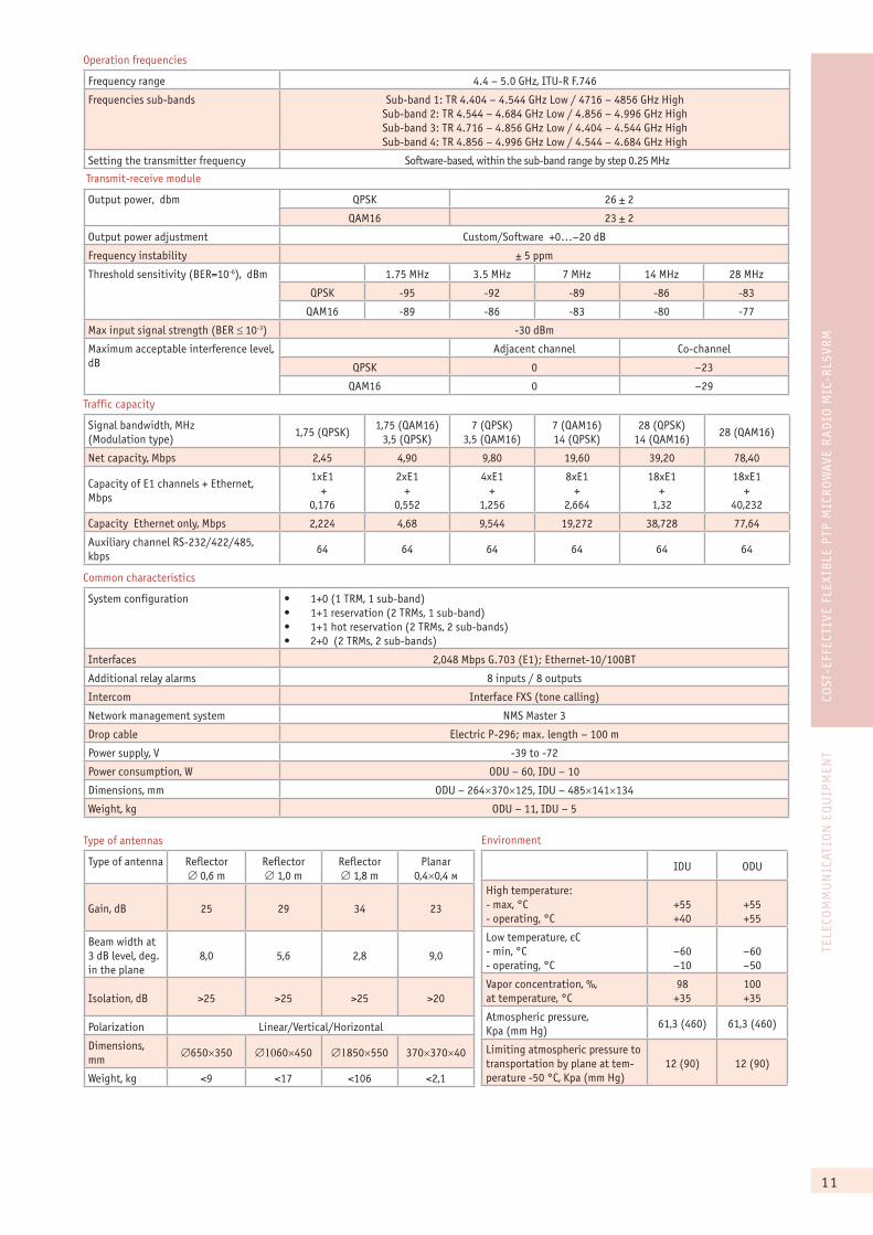
Traffic capacity
Signal bandwidth, MHz (Modulation type)
1,75 (QPSK)1,75 (QAM16)
3,5 (QPSK)7 (QPSK)
3,5 (QAM16)7 (QAM16)14 (QPSK)
28 (QPSK)14 (QAM16)
28 (QAM16)
Net capacity, Mbps 2,45 4,90 9,80 19,60 39,20 78,40
Capacity of Å1 channels + Ethernet, Mbps
1xE1 +
0,176
2xE1+
0,552
4xE1+
1,256
8xE1+
2,664
18xE1+
1,32
18xE1+
40,232
Capacity Ethernet only, Mbps 2,224 4,68 9,544 19,272 38,728 77,64
Auxiliary channel RS-232/422/485, kbps
64 64 64 64 64 64
Common characteristics
System configuration �� 1+0 (1 TRM, 1 sub-band)�� 1+1 reservation (2 TRMs, 1 sub-band)�� 1+1 hot reservation (2 TRMs, 2 sub-bands)�� 2+0 (2 TRMs, 2 sub-bands)
Interfaces 2,048 Mbps G.703 (Å1); Ethernet-10/100BT
Additional relay alarms 8 inputs / 8 outputs
Intercom Interface FXS (tone calling)
Network management system NMS Master 3
Drop cable Electric P-296; max. length – 100 m
Power supply, V -39 to -72
Power consumption, W ODU – 60, IDU – 10
Dimensions, mm ODU – 264�370�125, IDU – 485�141�134
Weight, kg ODU – 11, IDU – 5
Type of antennas
Type of antenna Reflector � 0,6 m
Reflector � 1,0 m
Reflector � 1,8 m
Planar 0,4�0,4 ì
Gain, dB 25 29 34 23
Beam width at 3 dB level, deg. in the plane
8,0 5,6 2,8 9,0
Isolation, dB >25 >25 >25 >20
Polarization Linear/Vertical/Horizontal
Dimensions, mm
�650�350 ���60�450 ��850�550 370�370�40
Weight, kg <9 <17 <106 <2,1
Environment
IDU ODU
High temperature:- max, °C- operating, °C
+55+40
+55+55
Low temperature, ºC- min, °C- operating, °C
–60–10
–60–50
Vapor concentration, %,at temperature, °Ñ
98+35
100+35
Atmospheric pressure, Kpa (mm Hg)
61,3 (460) 61,3 (460)
Limiting atmospheric pressure to transportation by plane at tem-perature -50 °C, Kpa (mm Hg)
12 (90) 12 (90)
Transmit-receive module
Output power, dbm QPSK 26 ± 2
QAM16 23 ± 2
Output power adjustment Custom/Software +0…–20 dB
Frequency instability ± 5 ppm
Threshold sensitivity (BER=10-6), dBm 1.75 MHz 3.5 MHz 7 MHz 14 MHz 28 MHz
QPSK -95 -92 -89 -86 -83
QAM16 -89 -86 -83 -80 -77
Max input signal strength (BER � 10-3) -30 dBm
Maximum acceptable interference level, dB
Adjacent channel Co-channel
QPSK 0 –23
QAM16 0 –29
Operation frequencies
Frequency range 4.4 – 5.0 GHz, ITU-R F.746
Frequencies sub-bands Sub-band 1: TR 4.404 – 4.544 GHz Low / 4716 – 4856 GHz HighSub-band 2: TR 4.544 – 4.684 GHz Low / 4.856 – 4.996 GHz HighSub-band 3: TR 4.716 – 4.856 GHz Low / 4.404 – 4.544 GHz HighSub-band 4: TR 4.856 – 4.996 GHz Low / 4.544 – 4.684 GHz High
Setting the transmitter frequency Software-based, within the sub-band range by step 0.25 MHz
12
TELE
COM
MU
NIC
ATIO
N E
QU
IPM
ENT
FULL
OU
TDO
OR
ETH
ERN
ET R
AD
IO M
IC-R
LPE
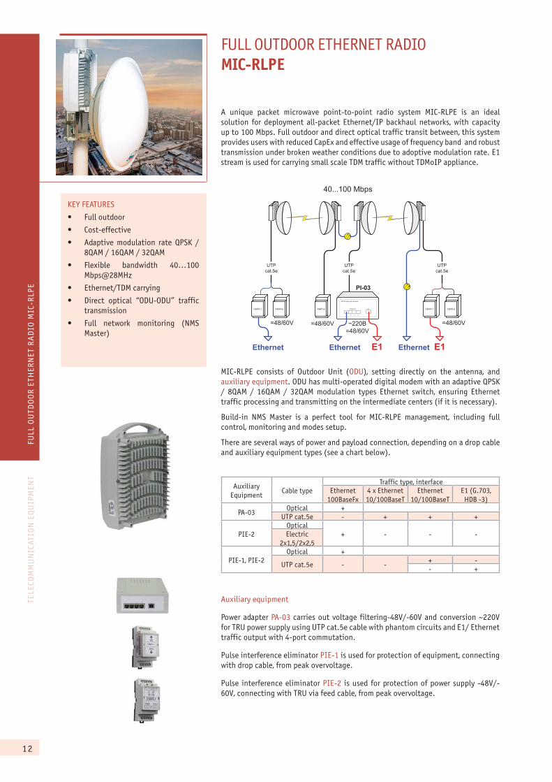
FULL OUTDOOR ETHERNET RADIOMIC-RLPE
A unique packet microwave point-to-point radio system MIC-RLPE is an ideal solution for deployment all-packet Ethernet/IP backhaul networks, with capacity up to 100 Mbps. Full outdoor and direct optical traffic transit between, this system provides users with reduced CapEx and effective usage of frequency band and robust transmission under broken weather conditions due to adoptive modulation rate. E1 stream is used for carrying small scale TDM traffic without TDMoIP appliance.
Auxiliary Equipment
Cable typeTraffic type, interface
Ethernet 100BaseFx
4 õ Ethernet 10/100BaseT
Ethernet 10/100BaseT
E1 (G.703, HDB -3)
PA-03Optical +
UTP cat.5e - + + +
PIE-2Optical
+ - - -Electric2õ1,5/2õ2,5
PIE-1, PIE-2Optical +
UTP cat.5e - -+ -- +
PI-03
40...100 Mbps
Ethernet E1
D�-03 DE�F�+� F�����(
21 3 4
E1Ethernet
~220�=48/60V
=48/60V =48/60V
E1
����-1 ����-2
Ethernet
����-2
=48/60V
����-1 ����-2
Ethernet
UTPcat.5e
UTPcat.5e
UTPcat.5e
MIC-RLPE consists of Outdoor Unit (ODU), setting directly on the antenna, and auxiliary equipment. ODU has multi-operated digital modem with an adaptive QPSK / 8QAM / 16QAM / 32QAM modulation types Ethernet switch, ensuring Ethernet traffic processing and transmitting on the intermediate centers (if it is necessary).
Build-in NMS Master is a perfect tool for MIC-RLPE management, including full control, monitoring and modes setup.
There are several ways of power and payload connection, depending on a drop cable and auxiliary equipment types (see a chart below).
Auxiliary equipment
Power adapter PA-03 carries out voltage filtering-48V/-60V and conversion ~220V for TRU power supply using UTP cat.5e cable with phantom circuits and E1/ Ethernet traffic output with 4-port commutation.
Pulse interference eliminator PIE-1 is used for protection of equipment, connecting with drop cable, from peak overvoltage.
Pulse interference eliminator PIE-2 is used for protection of power supply -48V/-60V, connecting with TRU via feed cable, from peak overvoltage.
KEY FEATURES
�� Full outdoor
�� Cost-effective
�� Adaptive modulation rate QPSK / 8QAM / 16QAM / 32QAM
�� Flexible bandwidth 40…100 Mbps@28MHz
�� Ethernet/TDM carrying
�� Direct optical “ODU-ODU” traffic transmission
�� Full network monitoring (NMS Master)
13
TELE
COM
MU
NIC
ATIO
N E
QU
IPM
ENT
FULL
OU
TDO
OR
ETH
ERN
ET R
AD
IO M
IC-R
LPE
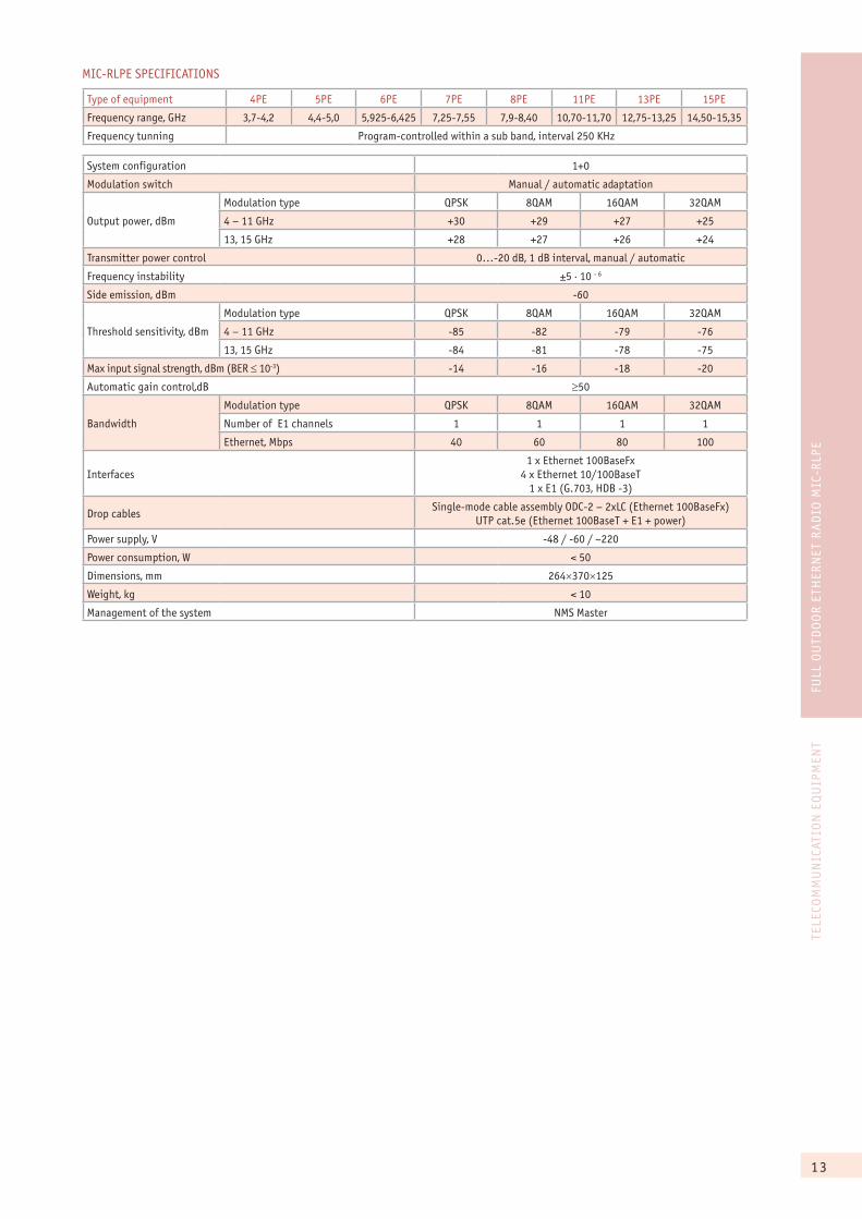
MIC-RLÐÅ SPECIFICATIONS
Type of equipment 4ÐÅ 5ÐÅ 6ÐÅ 7ÐÅ 8ÐÅ 11ÐÅ 13ÐÅ 15ÐÅ
Frequency range, GHz 3,7-4,2 4,4-5,0 5,925-6,425 7,25-7,55 7,9-8,40 10,70-11,70 12,75-13,25 14,50-15,35
Frequency tunning Program-controlled within a sub band, interval 250 KHz
System configuration 1+0
Modulation switch Manual / automatic adaptation
Output power, dBm
Modulation type QPSK 8QAM 16QAM 32QAM
4 – 11 GHz +30 +29 +27 +25
13, 15 GHz +28 +27 +26 +24
Transmitter power control 0…-20 dB, 1 dB interval, manual / automatic
Frequency instability ��������- 6
Side emission, dBm -60
Threshold sensitivity, dBm
Modulation type QPSK 8QAM 16QAM 32QAM
4 – 11 GHz -85 -82 -79 -76
13, 15 GHz -84 -81 -78 -75
Max input signal strength, dBm (BER � 10-3) -14 -16 -18 -20
Automatic gain control,dB �50
Bandwidth
Modulation type QPSK 8QAM 16QAM 32QAM
Number of Å1 channels 1 1 1 1
Ethernet, Mbps 40 60 80 100
Interfaces1 õ Ethernet 100BaseFx
4 õ Ethernet 10/100BaseT1 õ Å1 (G.703, HDB -3)
Drop cablesSingle-mode cable assembly ODC-2 – 2xLC (Ethernet 100BaseFx)
UTP cat.5e (Ethernet 100BaseT + E1 + power)
Power supply, V -48 / -60 / ~220
Power consumption, W < 50
Dimensions, mm 264�370�125
Weight, kg < 10
Management of the system NMS Master
14
TELE
COM
MU
NIC
ATIO
N E
QU
IPM
ENT
HIG
H-S
PEE
D F
LEXI
BLE
PTP
MIC
RO
WAV
E R
AD
IO M
IC-R
LP+
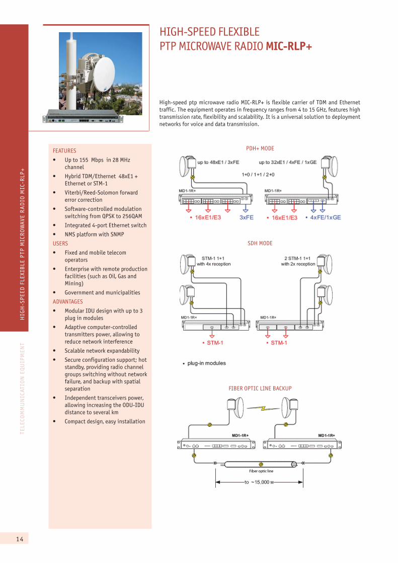
HIGH-SPEED FLEXIBLE PTP MICROWAVE RADIO MIC-RLP+
FEATURES
�� Up to 155 Mbps in 28 MHz channel
�� Hybrid TDM/Ethernet 48xE1 + Ethernet or STM-1
�� Viterbi/Reed-Solomon forward error correction
�� Software-controlled modulation switching from QPSK to 256QAM
�� Integrated 4-port Ethernet switch
�� NMS platform with SNMP
USERS
�� Fixed and mobile telecom operators
�� Enterprise with remote production facilities (such as Oil, Gas and Mining)
�� Government and municipalities
ADVANTAGES
�� Modular IDU design with up to 3 plug in modules
�� Adaptive computer-controlled transmitters power, allowing to reduce network interference
�� Scalable network expandability
�� Secure configuration support; hot standby, providing radio channel groups switching without network failure, and backup with spatial separation
�� Independent transceivers power, allowing increasing the ODU-IDU distance to several km
�� Compact design, easy installation
High-speed ptp microwave radio MIC-RLP+ is flexible carrier of TDM and Ethernet traffic. The equipment operates in frequency ranges from 4 to 15 GHz, features high transmission rate, flexibility and scalability. It is a universal solution to deployment networks for voice and data transmission.
PDH+ MODE
SDH MODE
FIBER OPTIC LINE BACKUP
15
TELE
COM
MU
NIC
ATIO
N E
QU
IPM
ENT
HIG
H-S
PEE
D F
LEXI
BLE
PTP
MIC
RO
WAV
E R
AD
IO M
IC-R
LP+
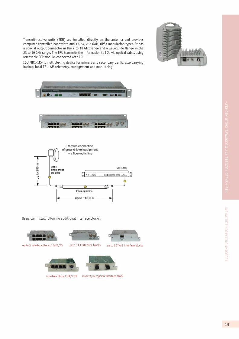
Transmit-receive units (TRU) are installed directly on the antenna and provides computer-controlled bandwidth and 16, 64, 256 QAM, QPSK modulation types. It has a coaxial output connector in the 7 to 18 GHz range and a waveguide flange in the 23 to 40 GHz range. The TRU transmits the information to IDU via optical cable, using removable SFP module, connected with IDU.
IDU MD1-1R+ is multiplexing device for primary and secondary traffic, also carrying backup, local TRU-AM telemetry, management and monitoring.
Users can install following additional interface blocks:
16
TELE
COM
MU
NIC
ATIO
N E
QU
IPM
ENT
HIG
H-S
PEE
D F
LEXI
BLE
PTP
MIC
RO
WAV
E R
AD
IO M
IC-R
LP+
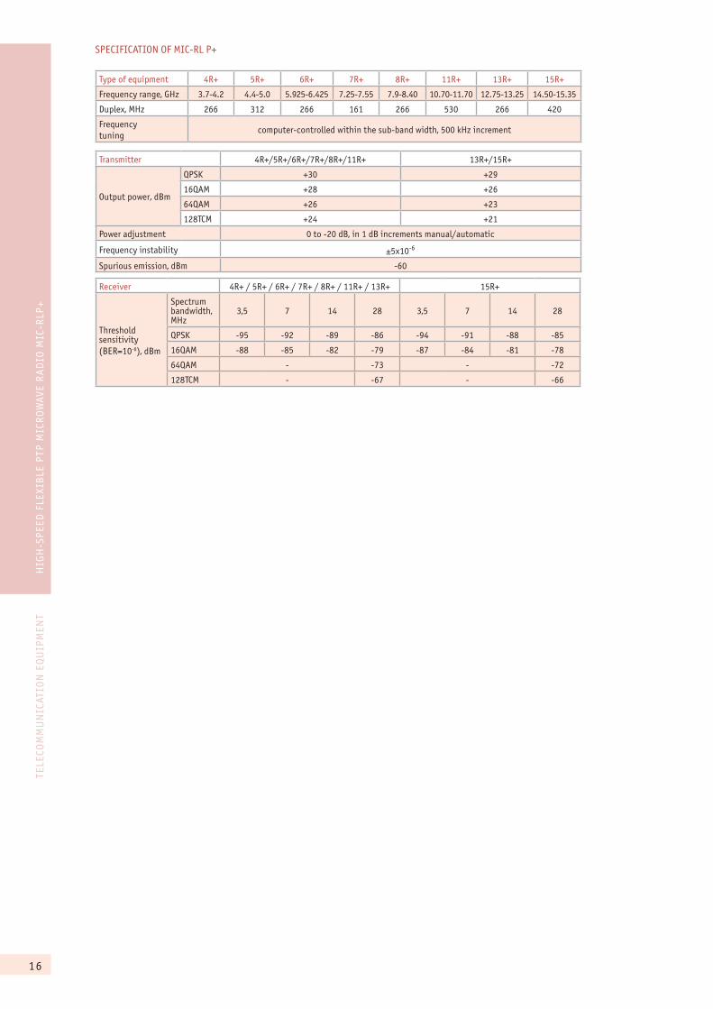
SPECIFICATION OF MIC-RL P+
Type of equipment 4R+ 5R+ 6R+ 7R+ 8R+ 11R+ 13R+ 15R+
Frequency range, GHz 3.7-4.2 4.4-5.0 5.925-6.425 7.25-7.55 7.9-8.40 10.70-11.70 12.75-13.25 14.50-15.35
Duplex, MHz 266 312 266 161 266 530 266 420
Frequency tuning
computer-controlled within the sub-band width, 500 kHz increment
Transmitter 4R+/5R+/6R+/7R+/8R+/11R+ 13R+/15R+
Output power, dBm
QPSK +30 +29
16QAM +28 +26
64QAM +26 +23
128TCM +24 +21
Power adjustment 0 to -20 dB, in 1 dB increments manual/automatic
Frequency instability ±5õ10-6
Spurious emission, dBm -60
Receiver 4R+ / 5R+ / 6R+ / 7R+ / 8R+ / 11R+ / 13R+ 15R+
Threshold sensitivity (BER=10-6), dBm
Spectrum bandwidth, MHz
3,5 7 14 28 3,5 7 14 28
QPSK -95 -92 -89 -86 -94 -91 -88 -85
16QAM -88 -85 -82 -79 -87 -84 -81 -78
64QAM - -73 - -72
128TCM - -67 - -66
17
TELE
COM
MU
NIC
ATIO
N E
QU
IPM
ENT
HIG
H-S
PEE
D F
LEXI
BLE
PTP
MIC
RO
WAV
E R
AD
IO M
IC-R
LP+
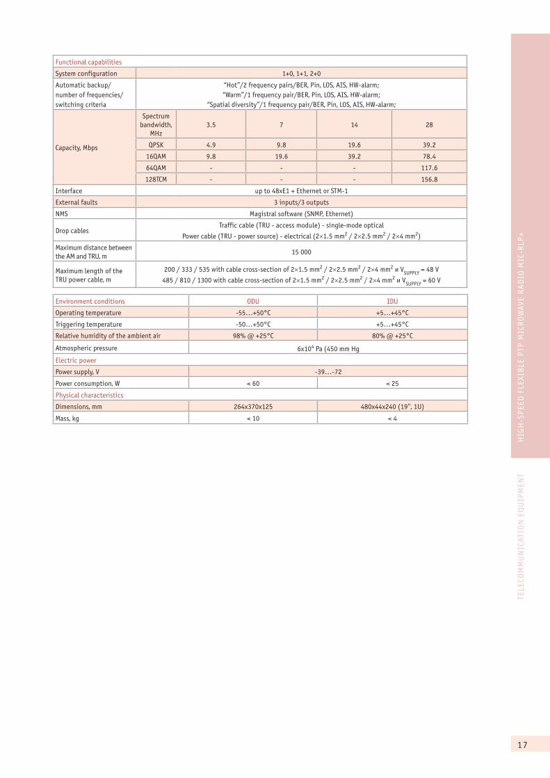
Functional capabilities
System configuration 1+0, 1+1, 2+0
Automatic backup/number of frequencies/switching criteria
“Hot”/2 frequency pairs/BER, Pin, LOS, AIS, HW-alarm;“Warm”/1 frequency pair/BER, Pin, LOS, AIS, HW-alarm;
“Spatial diversity”/1 frequency pair/BER, Pin, LOS, AIS, HW-alarm;
Capacity, Mbps
Spectrum bandwidth,
MHz3.5 7 14 28
QPSK 4.9 9.8 19.6 39.2
16QAM 9.8 19.6 39.2 78.4
64QAM - - - 117.6
128TCM - - - 156.8
Interface up to 48xE1 + Ethernet or STM-1
External faults 3 inputs/3 outputs
NMS Magistral software (SNMP, Ethernet)
Drop cablesTraffic cable (TRU - access module) - single-mode optical
Power cable (TRU - power source) - electrical (2�1.5 mm2 / 2�2.5 mm2 / 2�4 mm2)
Maximum distance between the AM and TRU, m
15 000
Maximum length of theTRU power cable, m
200 / 333 / 535 with cable cross-section of 2�1.5 mm2 / 2�2.5 mm2 / 2�4 mm2 è VSUPPLY
= 48 V
485 / 810 / 1300 with cable cross-section of 2�1.5 mm2 / 2�2.5 mm2 / 2�4 mm2 è VSUPPLY
= 60 V
Environment conditions ODU IDU
Operating temperature -55…+50°Ñ +5…+45°Ñ
Triggering temperature -50…+50°Ñ +5…+45°Ñ
Relative humidity of the ambient air 98% @ +25°Ñ 80% @ +25°Ñ
Atmospheric pressure 6õ104 Pa (450 mm Hg
Electric power
Power supply, V -39…-72
Power consumption, W < 60 < 25
Physical characteristics
Dimensions, mm 264õ370õ125 480õ44õ240 (19", 1U)
Mass, kg < 10 < 4
18
TELE
COM
MU
NIC
ATIO
N E
QU
IPM
ENT
WIR
ELR
SS B
ROA
DB
AND
SYS
TEM
WIM
IC-6
000
ÀP-02
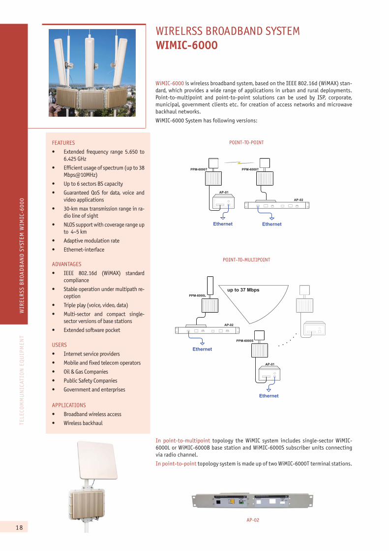
WIRELRSS BROADBAND SYSTEMWIMIC-6000
FEATURES
�� Extended frequency range 5.650 to 6.425 GHz
�� Efficient usage of spectrum (up to 38 Mbps@10MHz)
�� Up to 6 sectors BS capacity
�� Guaranteed QoS for data, voice and video applications
�� 30-km max transmission range in ra-dio line of sight
�� NLOS support with coverage range up to 4~5 km
�� Adaptive modulation rate
�� Ethernet-interface
ADVANTAGES
�� IEEE 802.16d (WiMAX) standard compliance
�� Stable operation under multipath re-ception
�� Triple play (voice, video, data)
�� Multi-sector and compact single-sector versions of base stations
�� Extended software pocket
USERS
�� Internet service providers
�� Mobile and fixed telecom operators
�� Oil & Gas Companies
�� Public Safety Companies
�� Government and enterprises
APPLICATIONS
�� Broadband wireless access
�� Wireless backhaul
WiMIC-6000 is wireless broadband system, based on the IEEE 802.16d (WiMAX) stan-dard, which provides a wide range of applications in urban and rural deployments. Point-to-multipoint and point-to-point solutions can be used by ISP, corporate, municipal, government clients etc. for creation of access networks and microwave backhaul networks.
WiMIC-6000 System has following versions:
Ethernet
�P-01
PPM-6000T PPM-6000T
�P-02
Ethernet
Ethernet
�P-01
up to 37 MbpsPPM-6000L
PPM-6000S
PPM-6000T
AP-02
Ethernet
POINT-TO-MULTIPOINT
POINT-TO-POINT
In point-to-multipoint topology the WiMIC system includes single-sector WiMIC-6000L or WiMIC-6000B base station and WiMIC-6000S subscriber units connecting via radio channel.
In point-to-point topology system is made up of two WiMIC-6000T terminal stations.
19
TELE
COM
MU
NIC
ATIO
N E
QU
IPM
ENT
WIR
ELR
SS B
ROA
DB
AND
SYS
TEM
WIM
IC-6
000
ÀP-01
WiMIC-6000B supports adaptively switching modulation and automatically driven bandwidth. Base station can include up to 6 sectors, providing aggregate through-put up to 222 Mbps.
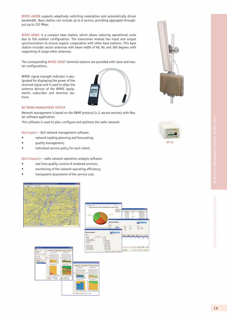
WiMIC-6000L is a compact base station, which allows reducing operational costs due to full outdoor configuration. The transceiver module has input and output synchronization to ensure organic cooperation with other base stations. This base station includes sector antennas with beam width of 60, 90, and 360 degrees with supporting of usage other antennas.
The corresponding WiMIC-6000T terminal stations are provided with slave and mas-ter configurations.
WiMIC signal strength indicator is des-ignated for displaying the power of the received signal and is used to align the antenna devices of the WiMIC equip-ment’s subscriber and terminal sta-tions.
NETWORK MANAGEMENT SYSTEM
Network management is based on the SNMP protocol (v.3, secure version) with Mas-ter software application.
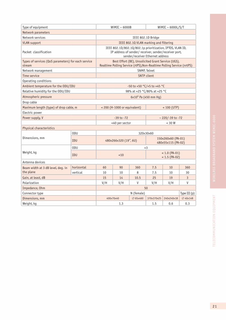
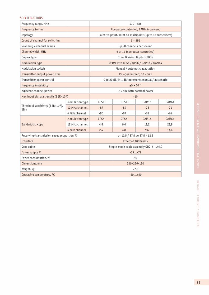
This software is used to plan, configure and optimize the radio network:
QoS-expert – QoS network management software:
�� �� ���� ��������������� ��������
�� ���������������
�� ����������������� ������ ����������!
QoS-Inspector - radio network operation analysis software:
�� ����������������� �� �� ��������������
�� � �� ���� ������� ��� ���������������
�� ����������������� ������������ ��!
20
TELE
COM
MU
NIC
ATIO
N E
QU
IPM
ENT
WIR
ELR
SS B
ROA
DB
AND
SYS
TEM
WIM
IC-6
000
SPECIFICATIONS
Type of equipment WiMIC – 6000B WiMIC – 6000L/S/T
Key features
Frequency range , MHz 5650~6425
Multiplexing user data technology (from BS to SU) TDM
Type of access to the transmission medium (from SU to BS) TDMA
Duplex type FDD or TDD
Modulation type adaptive from BPSK to 64QAM
Transmission technology OFDM-256
Spectral efficiency bps/Hz 5 (max)
Capacity, Mbps 37.67
Anti-jamming codification cascade type: Reed-Solomon/Vitrebi
Transmitter
Power, dBm up to +23
Output power adjustment software-based software-based (adaptive)
Dynamic range of output power adjustment, dB 10 30
Setting the transmitter frequency software-based, within the sub-band range
Transmission frequency instability ±5x10⁻⁶
Signal bandwidth, MHz 1.75/3.5/7/10
Capacity
(10 MHz band, BER=10-6), Mbps
BPSK (1/2) 4.19
QPSK (1/2) 8.37
QPSK (3/4) 12.56
16QAM (1/2) 16.64
16QAM (3/4) 25.11
64 QAM (2/3) 33.48
64QAM (3/4) 37.67
Receiver
Signal band, MHz 1.75/3.5/7/10
Threshold sensitivity
(10 MHz band, BER=10-6), dBm
BPSK -88
QPSK -84
16QAM -78
64QAM -70
Receiver dynamic range, not less than, dB 50
Max. input signal at the operating frequency, without dete-rioration of communication quality/ breakdown, dBm
25/0
21
TELE
COM
MU
NIC
ATIO
N E
QU
IPM
ENT
WIR
ELR
SS B
ROA
DB
AND
SYS
TEM
WIM
IC-6
000
Type of equipment WiMIC – 6000B WiMIC – 6000L/S/T
Network parameters
Network services IEEE 802.1D Bridge
VLAN support IEEE 802.1Q VLAN marking and filtering
Packet classificationIEEE 802.1D/802.1Q/802.1p prioritization, IPTOS, VLAN ID,
IP address of sender/ receiver, sender/receiver port, sender/receiver Ethernet address
Types of services (QoS parameters) for each service stream
Best Effort (BE), Unsolicited Grant Service (UGS), Realtime Polling Service (rtPS),Non-Realtime Polling Service (nrtPS)
Network management SNMP, Telnet
Time service SNTP client
Operating conditions
Ambient temperature for the ODU/IDU -50 to +50 °C/+5 to +45 °C
Relative humidity for the ODU/IDU 98% at +25 °C/80% at +25 °C
Atmospheric pressure 6x10⁴ Pa (450 mm Hg)
Drop cable
Maximum length (type) of drop cable, m < 200 (H-1000 or equivalent) < 100 (UTP)
Electric power
Power supply, V -39 to -72 ~ 220/-39 to -72
<40 per sector < 30 W
Physical characteristics
Dimensions, mmODU 320x30x60
IDU 480x266x320 (19”, 6U)150x260x60 (PA-01)480x55x115 (PA-02)
Weight, kgODU <3
IDU <10< 1.0 (PA-01)< 1.5 (PA-02)
Antenna devices
Beam width at 3 dB level, deg. in the plane
horizontal 60 90 360 7.5 10 360
vertical 10 10 8 7.5 10 30
Gain, at least, dB 15 14 10.5 25 19 3
Polarization V/H V/H V V/H V/H V
Impedance, Ohm 50
Connector type N (female) Type III (p)
Dimensions, mm 400x70x40 � 65x460 370x370x25 240x240x18 � 40x148
Weight, kg 1.3 1.5 0.6 0.3

22
TELE
COM
MU
NIC
ATIO
N E
QU
IPM
ENT
COG
NIT
IVE
BR
OAD
BAN
D S
YSTE
M M
IC-R
L500
CR
COGNITIVE BROADBAND SYSTEMMIC-RL500CR
Today when great amount of TV spectrum become open we have a unique opportunity of data transmission using 470 to 686 MHz bands. More than 100 MHz of spectrum divided into narrow bandwidths between TV channels, called White Spaces, open great prospect for rural and urban wireless broadband network deployment. Cognitive radio – a TV band device is breakthrough in sphere of such services as rural video transmission, Internet access and remote telemetry information collection
MIC-RL500CR is a cognitive radio system operating in TV spectrum of 470-686 MHz with point-to-point and point-to-multipoint topologies. It can automatically choose unused channels by access of white space database as well as on-line analysis of current interference situation.
FEATURES:High capacity64QAM modulation and operation in the 12 MHz band (due to adjacent channel teaming) provide capacity up to 29Mbps.
Robust transmission over long distancesDue to operation in 470-686 MHz band, high power output (up to 30 dBm), adaptive modulation rate from BPSK to QAM64 and OFDM-technology MIC-RL500CR guarantees steady long-range operation in nLOS/NLOS cases.
Flexible topology of network deploymentMIC-RL500CR allows working with point-to-point and point-to-multipoint topologies (up to 16 subscribers), transmitting about 88% of channel traffic in any direction - uplink or downlink.
Noise avoidanceImplementation of automatic power control and error-control coding make MIC-RL500CR to switch on another free channel in case of considerable noise level.
Self-contained operationMIC-RL500CR automatically finds white spaces, which cuts alignment time and guarantees steady operation when there is no contact with databases of available white spaces.
Ease of managementInternational network control protocol SNMP with Web-interface and NMS Master from MICRAN make available wide range features for management statistics analysis and system performance control.
Reducing of CAPEX and OPEXMIC-RL500CR is full outdoor station, using antennas with low wind profile, which requires small site preparation and allows reducing capital and operational costs.
point to point
NEW!
point to multipoint
=48/60� Ethernet
Up to 29 Mbps
=48/60� Ethernet
Up to 29 Mbps
up to 16subscribers
=48/60� Ethernet
APPLICATIONS:
�� Rural broadband access
�� Industrial-engineering com-munication for enterprises with remote production facilities
�� Video surveillance for vast areas
�� Temporary communications for public safety companies
Double Z antennawith TRU
Double LPA with TRU
TRU
23
TELE
COM
MU
NIC
ATIO
N E
QU
IPM
ENT
COG
NIT
IVE
BR
OAD
BAN
D S
YSTE
M M
IC-R
L500
CR
SPECIFICATIONS
Frequency range, MHz 470 - 686
Frequency tuning Computer-controlled, 1 MHz increment
Topology Point-to-point, point-to-multipoint (up to 16 subscribers)
Count of channel for switching 1 – 255
Scanning / channel search up 20 channels per second
Channel width, MHz 6 or 12 (computer-controlled)
Duplex type Time Division Duplex (TDD)
Modulation type OFDM with BPSK / QPSK / QAM16 / QAM64
Modulation switch Manual / automatic adaptation
Transmitter output power, dBm 22 –guaranteed; 30 - max
Transmitter power control 0 to 20 dB, in 1 dB increments manual / automatic
Frequency instability ������� - 6
Adjacent channel power -55 dBc with nominal power
Max input signal strength (BER=10-6) -10
Threshold sensitivity (BER=10-6), dBm
Modulation type BPSK QPSK QAM16 QAM64
12 MHz channel -87 -84 -78 -71
6 MHz channel -90 -87 -81 -74
Bandwidth, Mbps
Modulation type BPSK QPSK QAM16 QAM64
12 MHz channel 4,8 9,6 19,2 28,8
6 MHz channel 2,4 4,8 9,6 14,4
Receiving/transmission speed proportion, % îò 12,5 / 87,5 äî 87,5 / 12,5
Interface Ethernet 100BaseFx
Drop cable Single-mode cable assembly ODC-2 – 2xLC
Power supply, V -39…-72
Power consumption, W 50
Dimensions, mm 245x296x120
Weight, kg <7,5
Operating temperature, °C -50…+50