Embed Size (px)
Citation preview
NEED HELP? CALL US TOLL FREE AT 1-877-274-9362 1 TGC INSTALL INSTRUCTIONS
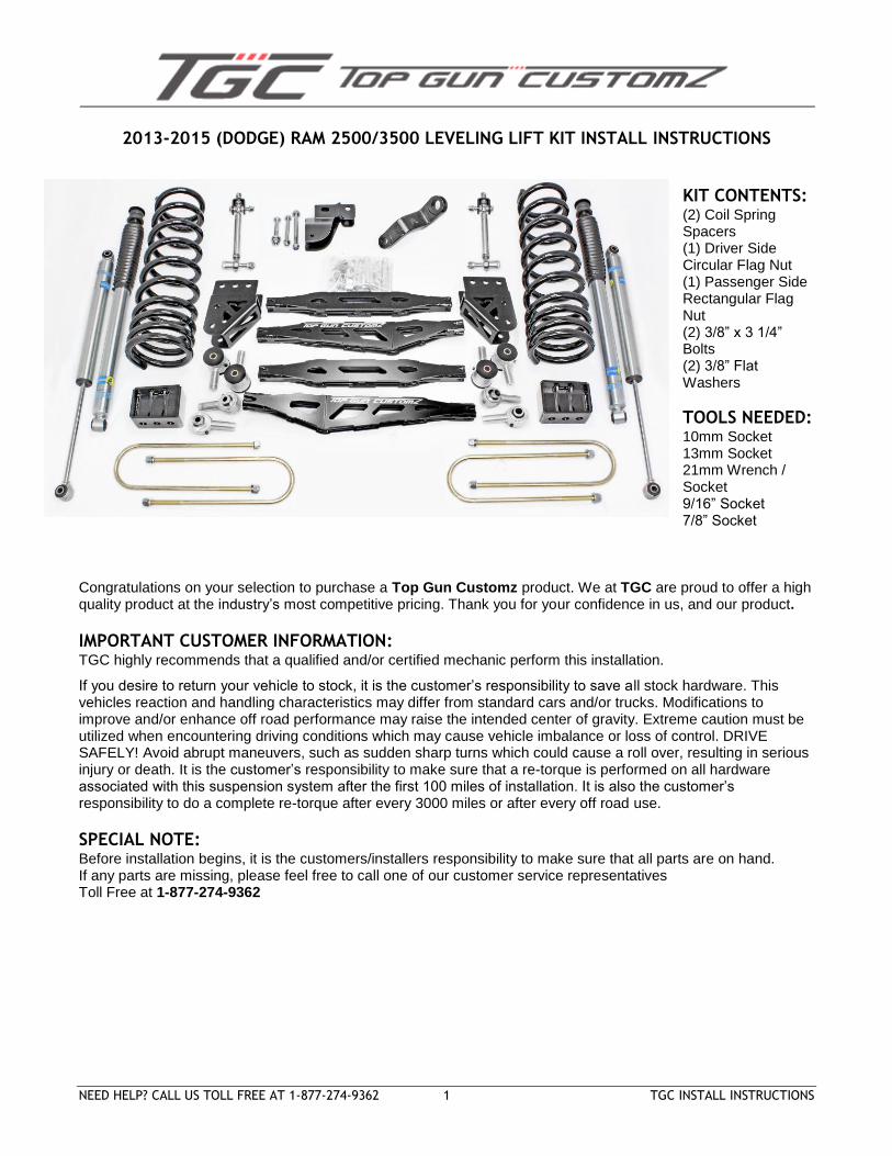
2013-2015 (DODGE) RAM 2500/3500 LEVELING LIFT KIT INSTALL INSTRUCTIONS
KIT CONTENTS: (2) Coil Spring Spacers (1) Driver Side Circular Flag Nut (1) Passenger Side Rectangular Flag Nut (2) 3/8” x 3 1/4” Bolts (2) 3/8” Flat Washers
TOOLS NEEDED:
10mm Socket 13mm Socket 21mm Wrench / Socket 9/16” Socket 7/8” Socket
Congratulations on your selection to purchase a Top Gun Customz product. We at TGC are proud to offer a high quality product at the industry’s most competitive pricing. Thank you for your confidence in us, and our product.
IMPORTANT CUSTOMER INFORMATION: TGC highly recommends that a qualified and/or certified mechanic perform this installation.
If you desire to return your vehicle to stock, it is the customer’s responsibility to save all stock hardware. This vehicles reaction and handling characteristics may differ from standard cars and/or trucks. Modifications to improve and/or enhance off road performance may raise the intended center of gravity. Extreme caution must be utilized when encountering driving conditions which may cause vehicle imbalance or loss of control. DRIVE SAFELY! Avoid abrupt maneuvers, such as sudden sharp turns which could cause a roll over, resulting in serious injury or death. It is the customer’s responsibility to make sure that a re-torque is performed on all hardware associated with this suspension system after the first 100 miles of installation. It is also the customer’s responsibility to do a complete re-torque after every 3000 miles or after every off road use.
SPECIAL NOTE:
Before installation begins, it is the customers/installers responsibility to make sure that all parts are on hand. If any parts are missing, please feel free to call one of our customer service representatives Toll Free at 1-877-274-9362
NEED HELP? CALL US TOLL FREE AT 1-877-274-9362 2 TGC INSTALL INSTRUCTIONS
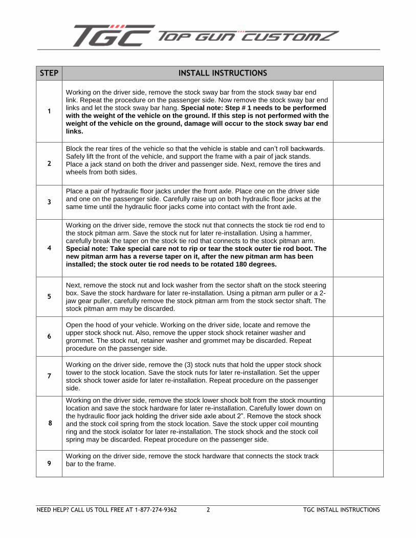
STEP INSTALL INSTRUCTIONS
1
Working on the driver side, remove the stock sway bar from the stock sway bar end link. Repeat the procedure on the passenger side. Now remove the stock sway bar end links and let the stock sway bar hang. Special note: Step # 1 needs to be performed with the weight of the vehicle on the ground. If this step is not performed with the weight of the vehicle on the ground, damage will occur to the stock sway bar end links.
2
Block the rear tires of the vehicle so that the vehicle is stable and can’t roll backwards. Safely lift the front of the vehicle, and support the frame with a pair of jack stands. Place a jack stand on both the driver and passenger side. Next, remove the tires and wheels from both sides.
3
Place a pair of hydraulic floor jacks under the front axle. Place one on the driver side and one on the passenger side. Carefully raise up on both hydraulic floor jacks at the same time until the hydraulic floor jacks come into contact with the front axle.
4
Working on the driver side, remove the stock nut that connects the stock tie rod end to the stock pitman arm. Save the stock nut for later re-installation. Using a hammer, carefully break the taper on the stock tie rod that connects to the stock pitman arm. Special note: Take special care not to rip or tear the stock outer tie rod boot. The new pitman arm has a reverse taper on it, after the new pitman arm has been installed; the stock outer tie rod needs to be rotated 180 degrees.
5
Next, remove the stock nut and lock washer from the sector shaft on the stock steering box. Save the stock hardware for later re-installation. Using a pitman arm puller or a 2-jaw gear puller, carefully remove the stock pitman arm from the stock sector shaft. The stock pitman arm may be discarded.
6
Open the hood of your vehicle. Working on the driver side, locate and remove the upper stock shock nut. Also, remove the upper stock shock retainer washer and grommet. The stock nut, retainer washer and grommet may be discarded. Repeat procedure on the passenger side.
7
Working on the driver side, remove the (3) stock nuts that hold the upper stock shock tower to the stock location. Save the stock nuts for later re-installation. Set the upper stock shock tower aside for later re-installation. Repeat procedure on the passenger side.
8
Working on the driver side, remove the stock lower shock bolt from the stock mounting location and save the stock hardware for later re-installation. Carefully lower down on the hydraulic floor jack holding the driver side axle about 2”. Remove the stock shock and the stock coil spring from the stock location. Save the stock upper coil mounting ring and the stock isolator for later re-installation. The stock shock and the stock coil spring may be discarded. Repeat procedure on the passenger side.
9 Working on the driver side, remove the stock hardware that connects the stock track bar to the frame.
NEED HELP? CALL US TOLL FREE AT 1-877-274-9362 3 TGC INSTALL INSTRUCTIONS
STEP INSTALL INSTRUCTIONS
10
Working on the driver side, remove the stock brake line bracket that connects the stock brake line between the stock upper and lower control arm mounts on the axle. Repeat procedure on the passenger side.
11 Working on the driver side, remove the stock lower control arm from the stock frame rail and axle location. Save the stock hardware for later re-installation. Remove the stock lower control arm and discard. Repeat procedure on the passenger side.
12
Working on the driver side, remove the stock upper control arm from the stock frame mount and axle location. The stock hardware may be discarded. Remove the stock upper control arm and discard. Repeat procedure on the passenger side. Special note: Due to clearance issues with the stock exhaust, the passenger side upper control arm frame mounting hardware will need to be cut off. Carefully cut the stock bolt and discard the stock hardware. New hardware is provided for the new upper control arms. Carefully pushing the stock exhaust over to the driver side will help make clearance to perform this step on the passenger side.
13 Using a cut off wheel, torch or plasma cutter remove the factory upper and lower control arm mounts from the frame. The remaining metal can be ground down smooth with the frame with a grinder. Repeat procedure on the passenger side.
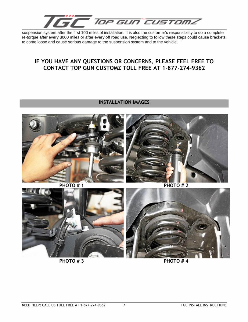
PHOTO # 1
14
Hold one of the new control arm mounts up to the frame just in front of the crossmember. There is an oval hole on the new control arm mounting bracket. Locate the same oval hole on the bottom side of the frame. Match these up to one another and that is where the mount will need to be placed. Make note of where to drill the mounting holes in the frame for the new mounts.
PHOTO # 2 , 3
15 Using drill bits or a uni-bit, drill the outer three holes to 7/8 of an inch. Drill the inside three holes to 5/8 of an inch. Repeat procedure on the passenger side.
PHOTO # 4
16
Using three metal 7/8” x 2.5” sleeves, insert them into the three 7/8” holes in the frame. With the three sleeves in position inside the frame, slide the new control arm bracket over the frame and insert three 5/8” bolts into the frame. Make sure a washer is installed on each bolt. Repeat procedure on the passenger side.
17
Set the new upper control arms at 28 ½” in length from center of mounting hole to center of mounting hole. The upper arms are the straight arms (not with the bend). Install the new arms with the rubber bushing end facing the new frame mount. MAKE SURE that the factory brake line is sitting on top of the upper control arm and not under it when installed. Refer to Photo # 4 for finished product.
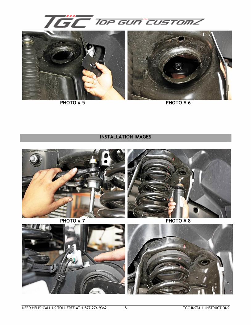
PHOTO # 5
18
Set the new lower control arms at 29 7/8” in length from center of mounting hole to center of mounting hole. The lower arms have the bend in them for tire clearance. Install the new arms with the rubber bushing end facing the new frame mount which will put the bend closer to the axle mount than to the frame mount. Refer to Photo # 4 for finished product.
PHOTO # 5
19
Locate the new front coil springs. Also, locate the stock upper coil mounting rings and the stock isolator. Carefully lower down on both hydraulic floor jacks enough so that the new coil springs can be installed. Working on the driver side, install the new coil into the stock lower and upper pocket. Make sure to install the stock isolator and the stock upper coil mounting ring. Raise up on the hydraulic floor jack until the new coil springs seat properly into the stock location. Repeat procedure on the passenger side.
NEED HELP? CALL US TOLL FREE AT 1-877-274-9362 4 TGC INSTALL INSTRUCTIONS
STEP INSTALL INSTRUCTIONS
20
Locate the new front shocks. The front shocks are shorter than the rear. If your new front shocks have a stem mount at the top then skip to step 21. Locate the stem to eye conversion bracket. Install the stem to eye conversion bracket inside the upper front shock tripod mount. The bottom of the shock requires a 9/16” sleeve and the top of the shock requires a ½” sleeve pressed into the rubber shock bushings.
PHOTO
# 6
21
Locate the stock lower shock hardware. Working on the driver side, secure the lower portion of the new shock into the stock lower location using the stock hardware. Make sure to use thread locker or lock tite and torque to 85 ft lbs. Repeat procedure on the passenger side.
22
Locate the stock upper shock tower (with the new stem to eye bracket now installed, if your shocks need it) and the stock hardware. Working on the driver side, install the stock upper shock tower into the stock location and secure using the ½” bolt provided in the stem to eye conversion kit. If you have a stem mounted shock then secure it with the provided hardware from your new shocks. Torque to 38 ft lbs. Special note: Make sure that the new shock that were installed in step # 21 fits properly into the upper shock tower and into the new stem to eye conversion bracket. Repeat procedure on the passenger side.
23
Locate the new track bar relocation bracket. Our bracket has a 5/8” hole for the track bar. Some earlier models use a smaller diameter track bar bolt. If your track bar bolt is smaller than 5/8”, we recommend you drill out the frame side of your track bar to 5/8” so there is no play in the track bar when it is mounted. Install the new track bar bracket up inside the factory track bar mounting location. Install the provided 5/8” x 3” Bolt through the hole where the factory track bar bolt used to be (may require drilling your factory track bar hole to 5/8” depending on year model). You will see a hole at the top of the new track bar bracket (up inside). Locate the ½” x 4 ½” bolt and install it up through the hole and into the factory hole in the crossmember. You will see another hole in the provided track bar bracket that is another optional mounting point to help secure the bracket. A hole must be drilled in the factory track bar mount to utilize this hole as another mounting point.
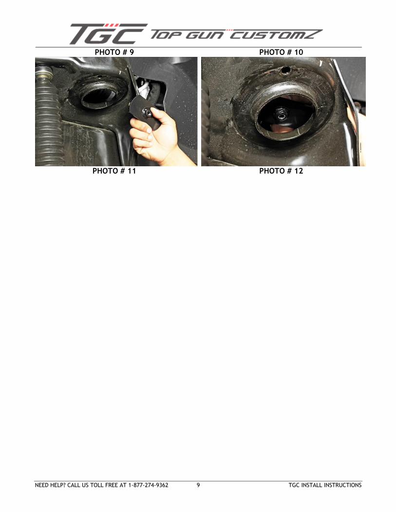
PHOTO # 7, 8
24 Bolt the new heavy duty sway bar end links into the factory lower mount. Do not install the top most “U shape” bracketry yet. We will install that later once the vehicle is on the ground.
PHOTO # 9,10
25 Locate the stock track bar bolt at the axle end. Also, locate the stock retaining nut. Re-install. Do not install the track bar into the new mount at this point.
26
Locate the new pitman arm and the stock pitman arm hardware. Install the new pitman arm into the stock location on the stock sector shaft and secure using the stock hardware. Make sure to use thread locker or lock tite. Torque the stock nut on the sector shaft to 225 ft lbs.
27
Locate the stock outer tie rod hardware. Special note: The new pitman arm has a reverse taper on it, if you have not already rotated the stock outer tie rod 180 degrees rotate the stock outer tie rod at this point. Secure the stock outer tie rod to the previously installed new pitman arm using the stock hardware. Make sure to use thread locker or lock tite. Torque to 85 ft lbs.
NEED HELP? CALL US TOLL FREE AT 1-877-274-9362 5 TGC INSTALL INSTRUCTIONS
STEP INSTALL INSTRUCTIONS
28 Remove the factory metal brake line bracket from the brake line. It is easiest to pry the bracket open to remove the brake line from the bracket. A new brake line bracket will be installed shortly.
29 Install the wheels/tires. Carefully remove both hydraulic floor jacks from under the front differential. Lower the vehicle to the ground.
30
Now that the front of the vehicle is back on the ground, install the new “U” shaped bracket onto the end of the sway bar with the bracket angled away from the coil spring. (Refer to image #10) Install the provided new sway bar end links into their new location and secure both upper and lower mounts with the provided ½” hardware.
PHOTO # 10
31 Install the brake line bracket as shown with the hardware provided. MAKE SURE there is enough slack in the brake line to turn the vehicle left and right.
PHOTO
# 11
32
Install the stock track bar into the newly installed track bar relocation bracket and secure using the new 14 mm x 80 mm bolt, flat washers and stock retaining nut. To make this job easier, have someone inside the vehicle turn the wheel left or right to line the bar up with the bracket, without starting the vehicle. Make sure to use thread locker or lock tite. Torque to 110 ft lbs.
Rear End Installations
33
To begin installation, block the front tires of the vehicle so that the vehicle is stable and can’t roll forward. Safely lift the rear of the vehicle and support the frame with a pair of jack stands. Place a jack stand on both the driver and passenger side. Next remove the wheels and tires from both sides.
34 Position a pair of hydraulic floor jacks under the rear axle. Place one jack stand on the driver side and one on the passenger side. Raise up on both hydraulic floor jacks at the same time until they make contact with the rear axle.
35 Working on the driver side, remove the stock shock from the stock location. Repeat procedure on the passenger side.
36 Working on the driver side, remove the (2) stock rear u-bolts. The stock rear u-bolts and hardware may be discarded. Set the stock upper u-bolt plate aside for later re-installation. Repeat procedure on passenger side.
37 Carefully lower down on both hydraulic floor jacks at the same time until the stock springs separate from the stock rear axle. Lower down approximately 4”. Special note: Make sure not to over extend any brake lines or hoses when lowering axle.
38
Locate (2) new 4” lifted rear blocks. Working on the driver side, install (1) new 4” lifted block between the stock rear axle and the stock spring assembly. Special note: The new 4” lifted block has a taper to it; the small end of the block needs to be installed towards the front of the vehicle. Repeat procedure on passenger side.
PHOTO # 12
39 Raise up on both hydraulic floor jacks at the same time until the driver and passenger side stock spring assembly seats flush with newly installed 4” block.
40 Install the new U-bolts with hardware and torque to 120 ft lbs
41 Install the rear wheels and tires and then remove all jack stands and floor jacks.
NEED HELP? CALL US TOLL FREE AT 1-877-274-9362 6 TGC INSTALL INSTRUCTIONS
STEP INSTALL INSTRUCTIONS
42 Install rear shocks making sure the upper and lower shock mount has a 9/16” sleeve inside the rubber bushing(s).
STEP POST INSTALL INSTRUCTIONS
1 Re torque all fasteners after 100 miles. Visually inspect components and re torque fasteners during routine vehicle service.
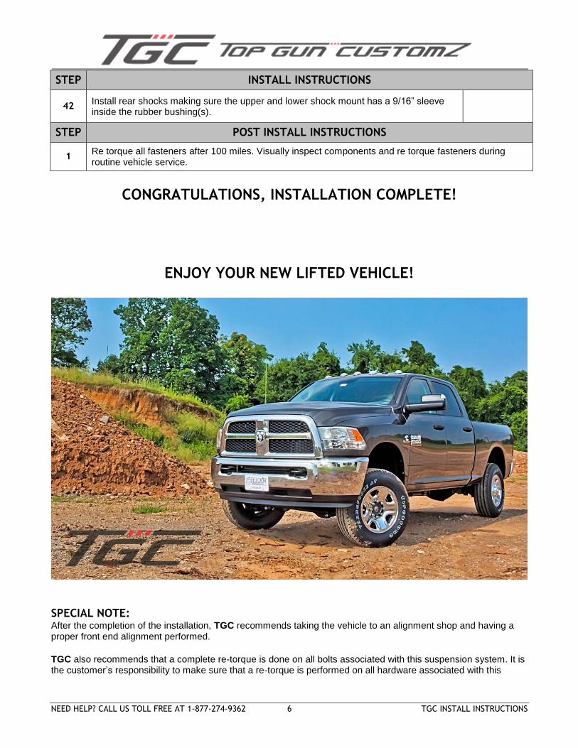
CONGRATULATIONS, INSTALLATION COMPLETE!
ENJOY YOUR NEW LIFTED VEHICLE!
SPECIAL NOTE: After the completion of the installation, TGC recommends taking the vehicle to an alignment shop and having a proper front end alignment performed.
TGC also recommends that a complete re-torque is done on all bolts associated with this suspension system. It is the customer’s responsibility to make sure that a re-torque is performed on all hardware associated with this
NEED HELP? CALL US TOLL FREE AT 1-877-274-9362 7 TGC INSTALL INSTRUCTIONS
suspension system after the first 100 miles of installation. It is also the customer’s responsibility to do a complete re-torque after every 3000 miles or after every off road use. Neglecting to follow these steps could cause brackets to come loose and cause serious damage to the suspension system and to the vehicle.
IF YOU HAVE ANY QUESTIONS OR CONCERNS, PLEASE FEEL FREE TO CONTACT TOP GUN CUSTOMZ TOLL FREE AT 1-877-274-9362
INSTALLATION IMAGES
PHOTO # 1 PHOTO # 2
PHOTO # 3 PHOTO # 4
NEED HELP? CALL US TOLL FREE AT 1-877-274-9362 8 TGC INSTALL INSTRUCTIONS
PHOTO # 5 PHOTO # 6
INSTALLATION IMAGES
PHOTO # 7 PHOTO # 8
NEED HELP? CALL US TOLL FREE AT 1-877-274-9362 9 TGC INSTALL INSTRUCTIONS
PHOTO # 9 PHOTO # 10
PHOTO # 11 PHOTO # 12