Embed Size (px)
Citation preview

ChargerOWNER’S MANUAL
SUPPLEMENT
2013
20
12
Pacif
ica
POL ICE
VEHICLES SOLD IN CANADA
With respect to any Vehicles Sold in Canada, the nameChrysler Group LLC shall be deemed to be deleted and thename Chrysler Canada Inc. used in substitution therefore.
DRIVING AND ALCOHOL
Drunken driving is one of the most frequent causes ofaccidents.Your driving ability can be seriously impaired with bloodalcohol levels far below the legal minimum. If you aredrinking, don’t drive. Ride with a designated non-drinkingdriver, call a cab, a friend, or use public transportation.
WARNING!
Driving after drinking can lead to an accident. Yourperceptions are less sharp, your reflexes are slower,and your judgment is impaired when you have beendrinking. Never drink and then drive.
This manual illustrates and describes the operation offeatures and equipment that are either standard or optionalon this vehicle. This manual may also include a descriptionof features and equipment that are no longer available orwere not ordered on this vehicle. Please disregard anyfeatures and equipment described in this manual that arenot on this vehicle.
Chrysler Group LLC reserves the right to make changes indesign and specifications, and/or make additions to orimprovements to its products without imposing any obliga-tion upon itself to install them on products previouslymanufactured.
Copyright © 2012 Chrysler Group LLC

TABLE OF CONTENTSSECTION PAGE
1 INTRODUCTION . . . . . . . . . . . . . . . . . . . . . . . . . . . . . . . . . . . . . . . . . . . . . . . . . . . . . . . . . . . . . 3
2 THINGS TO KNOW BEFORE STARTING YOUR VEHICLE . . . . . . . . . . . . . . . . . . . . . . . . . . . . . 5
3 UNDERSTANDING THE FEATURES OF YOUR VEHICLE . . . . . . . . . . . . . . . . . . . . . . . . . . . . . 19
4 UNDERSTANDING YOUR INSTRUMENT PANEL . . . . . . . . . . . . . . . . . . . . . . . . . . . . . . . . . . . 29
5 STARTING AND OPERATING . . . . . . . . . . . . . . . . . . . . . . . . . . . . . . . . . . . . . . . . . . . . . . . . . . 33
6 WHAT TO DO IN EMERGENCIES . . . . . . . . . . . . . . . . . . . . . . . . . . . . . . . . . . . . . . . . . . . . . . . 39
7 MAINTAINING YOUR VEHICLE . . . . . . . . . . . . . . . . . . . . . . . . . . . . . . . . . . . . . . . . . . . . . . . . 49
8 MAINTENANCE SCHEDULE . . . . . . . . . . . . . . . . . . . . . . . . . . . . . . . . . . . . . . . . . . . . . . . . . . . 53
9 INDEX . . . . . . . . . . . . . . . . . . . . . . . . . . . . . . . . . . . . . . . . . . . . . . . . . . . . . . . . . . . . . . . . . . . . 57
1
2
3
4
5
6
7
8
9


INTRODUCTION
CONTENTS� INTRODUCTION . . . . . . . . . . . . . . . . . . . . . . . .4
1

INTRODUCTION
This booklet is a supplement to the Owner’s Manualprepared with the assistance of service and engineeringspecialists, and is intended to aid the operators of policeor fleet vehicles (used in severe duty, high-mileage op-erations) in understanding the operation and requiredmaintenance procedures for such vehicles. It coversmaintenance procedures for vehicles equipped withheavy-duty packages. However, other vehicles operatedunder the conditions listed below are also considered“severe service” vehicles, and should be serviced andmaintained as prescribed in this booklet. This supple-ment applies to rear-wheel drive passenger cars only. Youare urged to read this publication and the Owner’sManual carefully.
Refer to the Police Upfitter’s Guide provided with yourvehicle, prior to the addition of any aftermarket equip-ment.
Following the instructions and recommendations pro-vided herein, will help assure safe and reliable operationof your vehicle. After you have read the booklet, it shouldbe stored in the vehicle for convenient reference andremain with the vehicle when sold.
4 INTRODUCTION
THINGS TO KNOW BEFORE STARTING YOUR VEHICLE
CONTENTS� MODIFIED REAR DOOR – LOCKS, LEVERS, AND
WINDOW SWITCHES — IF EQUIPPED . . . . . . . .6
� OCCUPANT RESTRAINTS . . . . . . . . . . . . . . . . .7
▫ Air Bag Deployment Zones . . . . . . . . . . . . . . . .8
2
MODIFIED REAR DOOR – LOCKS, LEVERS, ANDWINDOW SWITCHES — IF EQUIPPED
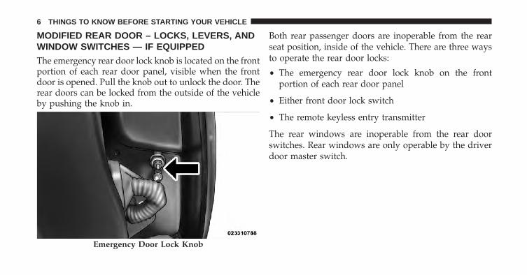
The emergency rear door lock knob is located on the frontportion of each rear door panel, visible when the frontdoor is opened. Pull the knob out to unlock the door. Therear doors can be locked from the outside of the vehicleby pushing the knob in.
Both rear passenger doors are inoperable from the rearseat position, inside of the vehicle. There are three waysto operate the rear door locks:
• The emergency rear door lock knob on the frontportion of each rear door panel
• Either front door lock switch
• The remote keyless entry transmitter
The rear windows are inoperable from the rear doorswitches. Rear windows are only operable by the driverdoor master switch.
Emergency Door Lock Knob
6 THINGS TO KNOW BEFORE STARTING YOUR VEHICLE
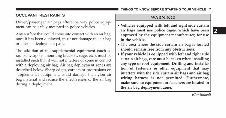
OCCUPANT RESTRAINTS
Driver/passenger air bags affect the way police equip-ment can be safely mounted in police vehicles.
Any surface that could come into contact with an air bag,once it has been deployed, must not damage the air bagor alter its deployment path.
The addition of the supplemental equipment (such asradios, weapons, mounting brackets, cage, etc.), must beinstalled such that it will not interfere or come in contactwith a deploying air bag. Air bag deployment zones aredescribed below. Sharp edges, corners or protrusions onsupplemental equipment, could damage the nylon airbag material and reduce the effectiveness of the air bagduring a deployment.
WARNING!
• Vehicles equipped with left and right side curtainair bags must use police cages, which have beenapproved by the equipment manufacturer, for usein the vehicle.
• The area where the side curtain air bag is locatedshould remain free from any obstructions.
• If your vehicle is equipped with left and right sidecurtain air bags, care must be taken when installingany type of roof equipment. Drilling and installa-tion of fasteners or other equipment that mayinterfere with the side curtain air bags and air bagwiring harness is not permitted. Furthermore,make sure no equipment or fasteners are located inthe air bag deployment zone.
(Continued)
2
THINGS TO KNOW BEFORE STARTING YOUR VEHICLE 7

WARNING! (Continued)• Do not place objects or mount equipment in front
of the air bag module cover, or in front of the seatareas that may come in contact with a deploying airbag.
• Dash, tunnel or console mounted equipmentshould not be placed outside of the specified zone.
• Failure to follow these instructions could result inpersonal injury.
Air Bag Deployment Zones
There are four zones to be aware of:
1. Driver Air Bag Deployment Zone (Figure 1), andDriver Air Bag/Steering Wheel Specifications (Figure2)
2. Passenger Air Bag Deployment Zone (Figure 3) and(Figure 4)
3. Supplemental Side Air Bag Inflatable Curtain (SABIC)Deployment Zone (Figure 5)
4. Supplemental Seat-Mounted Side Air Bag (SAB) De-ployment Zone (Figure 6)
8 THINGS TO KNOW BEFORE STARTING YOUR VEHICLE

Figure 1 - Driver Air Bag Deployment Zone, depicts thefollowing.
1. Vertical Plane Passing Through Center of SteeringWheel
2. 18.5 inches (47 cm)
3. Vertical Plane Passing Through Maximum RearwardPoint that the Driver Air Bag Cushion Reaches
4. Steering Wheel
5. Driver Air Bag Retainer/Housing
6. Driver Air Bag Cushion
Figure 1
2
THINGS TO KNOW BEFORE STARTING YOUR VEHICLE 9

DRIVER AIR BAG/STEERING COLUMN SPECIFI-CATIONS
DRIVER AIR BAG CUSHION POSITIONDAB Diameter When De-
ployed (Full)26.5 inches (67 cm)
DAB Depth When De-ployed (Full)
15 inches (38 cm)
Maximum Rearward Dis-placement During De-
ployment (Fill)
18.5 inches (47 cm)
STEERING COLUMN TILT POSITION RANGE+/– 2.7 Degrees from Steering Column Tilt Pivot
Point21.0 Degrees from Vertical is the Nominal Position
10 THINGS TO KNOW BEFORE STARTING YOUR VEHICLE
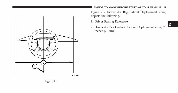
Figure 2 - Driver Air Bag Lateral Deployment Zone,depicts the following.
1. Driver Seating Reference
2. Driver Air Bag Cushion Lateral Deployment Zone, 28inches (71 cm).
Figure 2
2
THINGS TO KNOW BEFORE STARTING YOUR VEHICLE 11
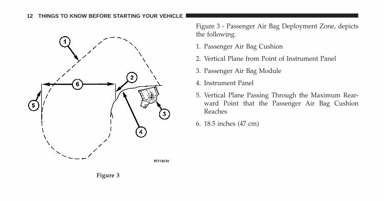
Figure 3 - Passenger Air Bag Deployment Zone, depictsthe following.
1. Passenger Air Bag Cushion
2. Vertical Plane from Point of Instrument Panel
3. Passenger Air Bag Module
4. Instrument Panel
5. Vertical Plane Passing Through the Maximum Rear-ward Point that the Passenger Air Bag CushionReaches
6. 18.5 inches (47 cm)
Figure 3
12 THINGS TO KNOW BEFORE STARTING YOUR VEHICLE

Figure 4 - Passenger Air Bag Lateral Deployment Zone,depicts the following.
1. 2.75 inches (7 cm)
2. Passenger Air Bag Cushion Deployment Zone
3. 20 inches (52 cm)
4. Reference Point
Figure 4
2
THINGS TO KNOW BEFORE STARTING YOUR VEHICLE 13

Figure 5
14 THINGS TO KNOW BEFORE STARTING YOUR VEHICLE

Figure 5 - Supplemental Side Air Bag Inflatable CurtainAir Bag Deployment Zone, depicts the following.
1. Cross-Sectional Area Side View
2. 8.7 inches (22 cm)
3. 3.5 inches (9 cm)
4. 17.7 inches (45 cm)
5. 40.7 inches (103.5 cm)
6. 19.8 inches (50.5 cm)
7. 3.5 inches (9 cm)
8. 14.5 inches (37 cm)
9. 16 inches (40.5 cm)
10. B-Pillar Trim
11. Side-Curtain Air Bag Inflator Module
12. 3.5 inches (9 cm)
2
THINGS TO KNOW BEFORE STARTING YOUR VEHICLE 15

Figure 6
16 THINGS TO KNOW BEFORE STARTING YOUR VEHICLE
Figure 6 - Supplemental Seat Mounted Side Air BagDeployment Zone, depicts the following.
1. Front Driver’s Seat
2. 17.7 in (45 cm)
3. 7.87 in (20 cm)
4. 7.87 in (20 cm)
5. Seat-Mounted Air Bag
2
THINGS TO KNOW BEFORE STARTING YOUR VEHICLE 17

UNDERSTANDING THE FEATURES OF YOUR VEHICLE
CONTENTS� LIGHTS . . . . . . . . . . . . . . . . . . . . . . . . . . . . . .20
▫ Stealth Mode . . . . . . . . . . . . . . . . . . . . . . . . .20
▫ Spot Lights — If Equipped. . . . . . . . . . . . . . . .21
▫ Dome Light — If Equipped . . . . . . . . . . . . . . .21
� ADJUSTABLE PEDALS — IF EQUIPPED . . . . . .22
� ELECTRICAL POWER OUTLETS . . . . . . . . . . . .24
▫ Front Power Outlet . . . . . . . . . . . . . . . . . . . . .24
▫ Additional Power Leads . . . . . . . . . . . . . . . . .25
� CONSOLE FEATURES . . . . . . . . . . . . . . . . . . . .27
▫ Equipment Mounting Bracket — If Equipped. . .27
3
LIGHTS
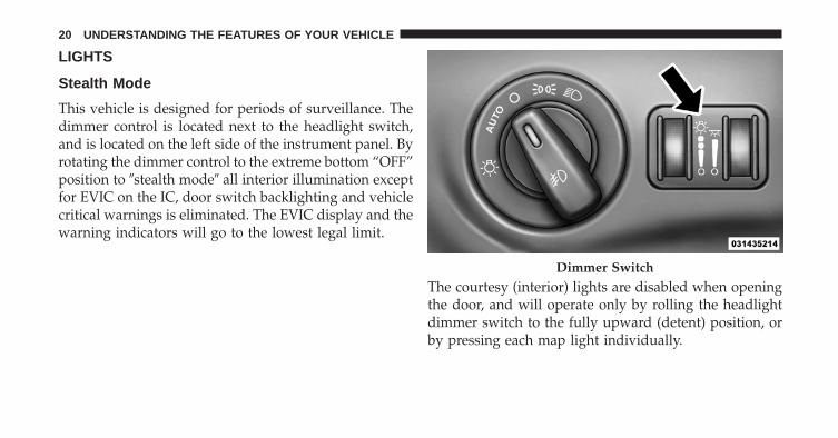
Stealth Mode
This vehicle is designed for periods of surveillance. Thedimmer control is located next to the headlight switch,and is located on the left side of the instrument panel. Byrotating the dimmer control to the extreme bottom “OFF”position to �stealth mode� all interior illumination exceptfor EVIC on the IC, door switch backlighting and vehiclecritical warnings is eliminated. The EVIC display and thewarning indicators will go to the lowest legal limit.
The courtesy (interior) lights are disabled when openingthe door, and will operate only by rolling the headlightdimmer switch to the fully upward (detent) position, orby pressing each map light individually.
Dimmer Switch
20 UNDERSTANDING THE FEATURES OF YOUR VEHICLE
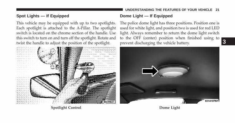
Spot Lights — If Equipped
This vehicle may be equipped with up to two spotlights.Each spotlight is attached to the A-Pillar. The spotlightswitch is located on the chrome section of the handle. Usethis switch to turn on and turn off the spotlight. Rotate andtwist the handle to adjust the position of the spotlight.
Dome Light — If Equipped
The police dome light has three positions. Position one isused for white light, and position two is used for red LEDlight. Always remember to return the dome light switchto the OFF (center) position when finished using toprevent discharging the vehicle battery.
Spotlight Control Dome Light
3
UNDERSTANDING THE FEATURES OF YOUR VEHICLE 21

ADJUSTABLE PEDALS — IF EQUIPPED
The adjustable pedals system is designed to allow agreater range of driver comfort for steering wheel tilt andseat position. This feature allows the brake and accelera-tor pedals to move toward or away from the driver toprovide improved position with the steering wheel.
The switch is located on the front side of the driver’s seatcushion side shield.
Adjustable Pedal Switch
22 UNDERSTANDING THE FEATURES OF YOUR VEHICLE
Press the switch forward to move the pedals forward(toward the front of the vehicle).
Press the switch rearward to move the pedals rearward(toward the driver).
• The pedals can be adjusted with the ignition OFF.
• The pedals can be adjusted while driving.
• The pedals cannot be adjusted when the vehicle is inREVERSE or when the Electronic Speed Control Sys-tem is on. The following messages will be displayed onvehicles equipped with the Electronic Vehicle Informa-tion System (EVIC) if the pedals are attempted to beadjusted when the system is locked out (“AdjustablePedal Disabled — Cruise Control Engaged” or “Ad-justable Pedal Disabled — Vehicle In Reverse”.
CAUTION!
Do not place any article under the adjustable pedalsor impede its ability to move as it may cause damageto the pedal controls. Pedal travel may become lim-ited if movement is stopped by an obstruction in theadjustable pedal’s path.
WARNING!
Do not adjust the pedals while the vehicle is moving.You could lose control and have an accident. Alwaysadjust the pedals while the vehicle is parked.
3
UNDERSTANDING THE FEATURES OF YOUR VEHICLE 23

ELECTRICAL POWER OUTLETS
Front Power Outlet
The front 12 Volt electrical power outlet is located on thecenter console, and is protected by a fuse. This poweroutlet is powered directly from the battery (power avail-able at all times). Items plugged into this power outletmay discharge the battery and/or prevent the enginefrom starting.
This outlet will also operate a conventional cigar lighterunit.
Front Power Outlet
24 UNDERSTANDING THE FEATURES OF YOUR VEHICLE

NOTE: Fuse 18, in the rear Power Distribution Center,not only protects the front power outlet, it also deter-mines whether the battery or the ignition switch willpower this outlet. One side of the three-terminal connec-tor that holds Fuse 18 receives battery power, and theother side receives ignition power. To change the powersource, install the fuse in either the upper or the lowerposition of the three-terminal Fuse 18 connector.
Additional Power Leads
There are additional 12 Volt electrical power leads under-neath an access cover, located directly under the centerconsole front power outlet. These power leads are pro-tected by fuses located on the passenger side below theglove compartment. Refer to the Police Upfitter’s Guideprovided with your vehicle, for more details. Carefullypry off the access cover to access the power leads.
WARNING!
To avoid serious injury or death:• Do not use a three-prong adaptor.• Do not insert any objects into the receptacles.
(Continued)
Access Cover
3
UNDERSTANDING THE FEATURES OF YOUR VEHICLE 25

WARNING! (Continued)• Do not touch with wet hands.• Close the lid when not in use.• If this outlet is mishandled, it may cause an electric
shock and failure.
CAUTION!
• Many accessories that can be plugged in drawpower from the vehicle’s battery even when not inuse (i.e., cellular phones, etc.). Eventually, ifplugged in long enough, the vehicle’s battery willdischarge sufficiently to degrade battery life and/orprevent the engine from starting.
(Continued)
CAUTION! (Continued)• Accessories that draw higher power (i.e., coolers,
vacuum cleaners, lights, etc.) will degrade the bat-tery even more quickly. Only use these intermit-tently and with greater caution.
• After the use of high power draw accessories orlong periods of the vehicle not being started (withaccessories still plugged in), the vehicle must bedriven a sufficient length of time to allow thealternator to recharge the vehicle’s battery.
• Power outlets are designed for accessory plugsonly. Do not hang any type of accessory or acces-sory bracket from the plug. Improper use of thepower outlet can cause damage.
26 UNDERSTANDING THE FEATURES OF YOUR VEHICLE

CONSOLE FEATURES
Equipment Mounting Bracket — If Equipped
The equipment mounting bracket is located between thedriver’s and front passenger’s seat. Refer to the PoliceUpfitter’s Guide (www.fleet.chrysler.com) for details.
Equipment Mounting Bracket
3
UNDERSTANDING THE FEATURES OF YOUR VEHICLE 27


UNDERSTANDING YOUR INSTRUMENT PANEL
CONTENTS� ELECTRONIC VEHICLE INFORMATION CENTER
(EVIC) . . . . . . . . . . . . . . . . . . . . . . . . . . . . . . .30
▫ Hour Meter . . . . . . . . . . . . . . . . . . . . . . . . . .32 4

ELECTRONIC VEHICLE INFORMATION CENTER(EVIC)
The Electronic Vehicle Information Center (EVIC) fea-tures a driver-interactive display that is located in theinstrument cluster.
This system allows the driver to select a variety of usefulinformation by pressing the switches mounted on thesteering wheel. The EVIC consists of the following:
• System status
• Vehicle information warning message displays
• Personal Settings (Customer-Programmable Features)
• Outside temperature display
• Trip computer functions
• Audio mode display
The system allows the driver to select information bypressing the following buttons mounted on the steeringwheel.
Electronic Vehicle Information Center (EVIC)
30 UNDERSTANDING YOUR INSTRUMENT PANEL

UP Button
Press and release the UP button to scroll up-ward through the main menus (Fuel Economy,Vehicle Info, Tire PSI, Cruise, Messages, Units,System Setup) and sub menus.
DOWN Button
Press and release the DOWN button to scrolldownward through the main menus and submenus.
SELECT Button
Press and release the SELECT button for accessto main menus, sub menus or to select apersonal setting in the setup menu. Press andhold the SELECT button for two seconds toreset features.
BACK Button
Press the BACK button to scroll back to aprevious menu or sub menu.
EVIC Steering Wheel Buttons
4
UNDERSTANDING YOUR INSTRUMENT PANEL 31

Hour Meter
1. With the engine running, press the UP or DOWNbuttons to scroll through the screens until you reachthe Vehicle Info screen.
2. Press the SELECT button.
3. Press the DOWN button until you reach the EngineHour screen.
32 UNDERSTANDING YOUR INSTRUMENT PANEL
STARTING AND OPERATING
CONTENTS� AUTOMATIC TRANSMISSION . . . . . . . . . . . . .34
▫ Shift Lever . . . . . . . . . . . . . . . . . . . . . . . . . . .34
� AUTOSTICK� . . . . . . . . . . . . . . . . . . . . . . . . . .34
▫ AutoStick� Operation . . . . . . . . . . . . . . . . . . .35
� VEHICLE LOADING . . . . . . . . . . . . . . . . . . . . .36
5

AUTOMATIC TRANSMISSION
Shift Lever
The shift lever is located on the steering column. Refer tothe Owner’s Manual for specific details about shifting.
AUTOSTICK�
AutoStick� is a driver-interactive transmission featureproviding manual shift control, giving you more controlof the vehicle. AutoStick� allows you to maximize enginebraking, eliminate undesirable upshifts and downshifts,and improve overall vehicle performance. This systemcan also provide you with more control during passing,city driving, cold slippery conditions, mountain driving,trailer towing, and many other situations.
Shift Lever
34 STARTING AND OPERATING

AutoStick� Operation
To activate AutoStick� mode, press and release theAUTOSTICK ON/OFF switch (on the end of the shiftlever) at any time while in the DRIVE position. A number
(indicating the current transmission gear) will be illumi-nated in the transmission gear display (located in theinstrument cluster) while AutoStick� mode is active.
In AutoStick� mode, pressing the AUTOSTICK up (+) ordown (-) switch allows you to select a higher or lowergear. Pressing the bottom of the switch (-) triggers adownshift (unless it would cause engine overspeeding),and pressing the top of the switch (+) triggers an upshift(unless it would cause engine lugging). The transmissionwill remain in the current gear until an upshift ordownshift is chosen. The transmission will automaticallydownshift as the vehicle slows to a stop (to preventengine lugging) and will display the current gear. Press-ing the top of the switch (+) when at a stop will allowstarting in second gear. After a stop, the driver shouldmanually upshift (+) the transmission as the vehicle isaccelerated.
AutoStick� Switch
5
STARTING AND OPERATING 35

Fully pressing the accelerator pedal while in AutoStick�mode will downshift the transmission as needed formaximum acceleration.
To exit the AutoStick� mode, perform either of thefollowing:
• Press and release the AUTOSTICK ON/OFF switch.The transmission will now operate automatically;shifting between the five available gears. You can shiftin or out of AutoStick� mode at any time withouttaking your foot off the accelerator pedal.
• Bring the vehicle to a complete stop, and place the shiftlever in the PARK or NEUTRAL position.
VEHICLE LOADING
The load carrying capacity of your vehicle is shown onthe “Vehicle Certification Label.” This label is attached tothe rear of the driver’s door. Do not exceed the GrossVehicle Weight Rating (GVWR) or Gross Axle WeightRating (GAWR) specified on the label.
While the weights and capacities shown in these tables isintended as supplemental loading information for pas-senger and luggage, the “Vehicle Certification Label”contains the most current load capacities and therefore, ifdifferent, will supersede the data in these tables. Refer tothe Owner’s Manual for more information.
Gross Vehicle Weight Rating (GVWR)
Charger Police Vehicles 5,500 lbs (2 495 kg)
36 STARTING AND OPERATING
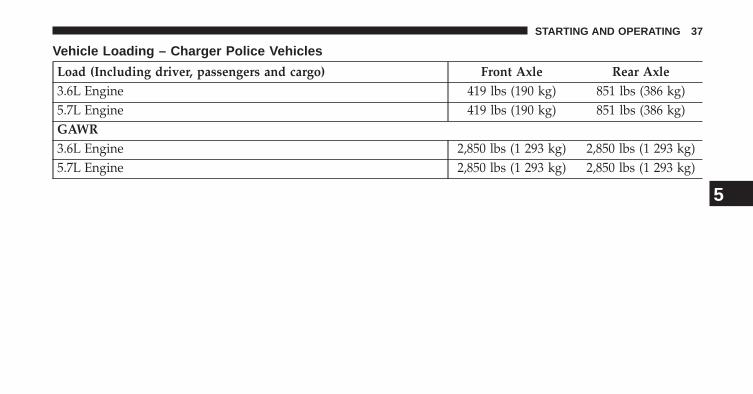
Vehicle Loading – Charger Police Vehicles
Load (Including driver, passengers and cargo) Front Axle Rear Axle3.6L Engine 419 lbs (190 kg) 851 lbs (386 kg)5.7L Engine 419 lbs (190 kg) 851 lbs (386 kg)GAWR3.6L Engine 2,850 lbs (1 293 kg) 2,850 lbs (1 293 kg)5.7L Engine 2,850 lbs (1 293 kg) 2,850 lbs (1 293 kg)
5
STARTING AND OPERATING 37

WHAT TO DO IN EMERGENCIES
CONTENTS� JACKING AND TIRE CHANGING . . . . . . . . . . .40
▫ Jack Location/Spare Tire Stowage . . . . . . . . . .41
▫ Preparations For Jacking . . . . . . . . . . . . . . . . .42
▫ Jacking And Changing A Tire . . . . . . . . . . . . .43
▫ Road Tire Installation. . . . . . . . . . . . . . . . . . . .47
▫ Center Cap Installation — If Equipped . . . . . . .47
6

JACKING AND TIRE CHANGING
WARNING!
• Do not attempt to change a tire on the side of thevehicle close to moving traffic. Pull far enough offthe road to avoid the danger of being hit whenoperating the jack or changing the wheel.
• Being under a jacked-up vehicle is dangerous. Thevehicle could slip off the jack and fall on you. Youcould be crushed. Never put any part of your bodyunder a vehicle that is on a jack.
(Continued)
WARNING! (Continued)• Never start or run the engine while the vehicle is
on a jack. If you need to get under a raised vehicle,take it to a service center where it can be raised ona lift.
• The jack is designed to be used as a tool forchanging tires only. The jack should not be used tolift the vehicle for service purposes. The vehicleshould be jacked on a firm level surface only.Avoid ice or slippery areas.
40 WHAT TO DO IN EMERGENCIES
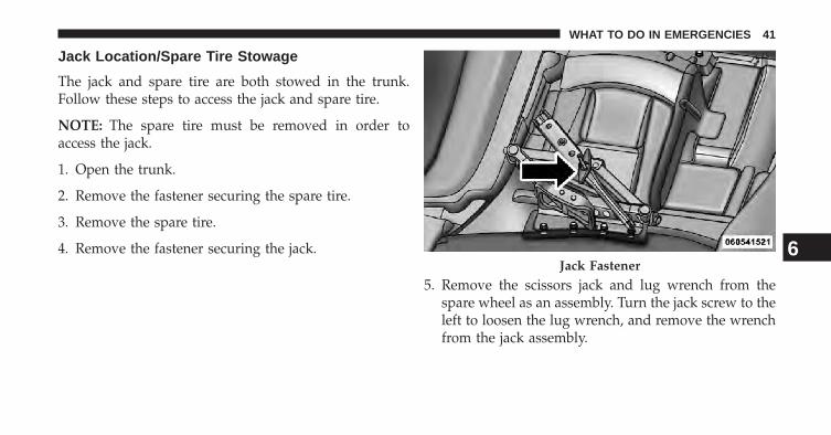
Jack Location/Spare Tire Stowage
The jack and spare tire are both stowed in the trunk.Follow these steps to access the jack and spare tire.
NOTE: The spare tire must be removed in order toaccess the jack.
1. Open the trunk.
2. Remove the fastener securing the spare tire.
3. Remove the spare tire.
4. Remove the fastener securing the jack.
5. Remove the scissors jack and lug wrench from thespare wheel as an assembly. Turn the jack screw to theleft to loosen the lug wrench, and remove the wrenchfrom the jack assembly.
Jack Fastener6
WHAT TO DO IN EMERGENCIES 41

WARNING!
• A loose tire or jack thrown forward in a collision orhard stop could endanger the occupants of thevehicle.
• Always stow the jack parts and the spare tire in theplaces provided. Have the deflated (flat) tire re-paired or replaced immediately.
Preparations For Jacking
1. Park the vehicle on a firm, level surface as far from theedge of the roadway as possible. Avoid icy or slipperyareas.
WARNING!
Do not attempt to change a tire on the side of thevehicle close to moving traffic, pull far enough off
(Continued)
WARNING! (Continued)the road to avoid the danger of being hit whenoperating the jack or changing the wheel.
2. Turn on the hazard warning flasher.
3. Set the parking brake.
4. Place the shift lever into PARK.
5. Turn OFF the ignition.
6. Block the front and rear of the wheel diagonallyopposite of the jacking position. For example, if chang-ing the right front tire, block the left rear wheel.
NOTE: Passengers should not remain in the vehiclewhen the vehicle is being jacked.
42 WHAT TO DO IN EMERGENCIES
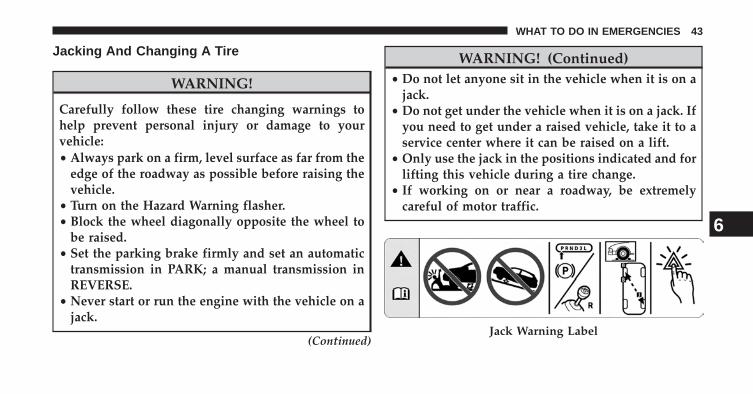
Jacking And Changing A Tire
WARNING!
Carefully follow these tire changing warnings tohelp prevent personal injury or damage to yourvehicle:• Always park on a firm, level surface as far from the
edge of the roadway as possible before raising thevehicle.
• Turn on the Hazard Warning flasher.• Block the wheel diagonally opposite the wheel to
be raised.• Set the parking brake firmly and set an automatic
transmission in PARK; a manual transmission inREVERSE.
• Never start or run the engine with the vehicle on ajack.
(Continued)
WARNING! (Continued)• Do not let anyone sit in the vehicle when it is on a
jack.• Do not get under the vehicle when it is on a jack. If
you need to get under a raised vehicle, take it to aservice center where it can be raised on a lift.
• Only use the jack in the positions indicated and forlifting this vehicle during a tire change.
• If working on or near a roadway, be extremelycareful of motor traffic.
Jack Warning Label
6
WHAT TO DO IN EMERGENCIES 43

CAUTION!
Do not attempt to raise the vehicle by jacking onlocations other than those indicated in the JackingInstructions for this vehicle.
1. Remove the spare tire, jack, and lug wrench.
2. Before raising the vehicle, use the lug wrench toloosen, but not remove, the lug nuts on the wheel withthe flat tire. Turn the lug nuts counterclockwise oneturn while the wheel is still on the ground.
3. Place the jack underneath the lift area that is closest tothe flat tire. Turn the jack screw clockwise to firmlyengage the jack saddle with the lift area of the sillflange.
Front Jacking Location
44 WHAT TO DO IN EMERGENCIES

4. Raise the vehicle just enough to remove the flat tireand install the spare tire.
WARNING!
Raising the vehicle higher than necessary can makethe vehicle less stable. It could slip off the jack andhurt someone near it. Raise the vehicle only enoughto remove the tire.
5. Remove the lug nuts and tire.
6. Mount the spare tire.
CAUTION!
Be sure to mount the spare tire with the valve stemfacing outward. The vehicle could be damaged if thespare tire is mounted incorrectly.
NOTE:
• For vehicles so equipped, do not attempt to install acenter cap or wheel cover on the compact spare.
Rear Jacking Location6
WHAT TO DO IN EMERGENCIES 45
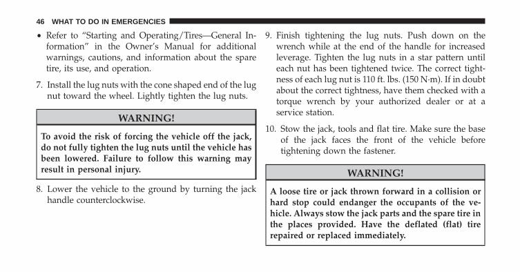
• Refer to “Starting and Operating/Tires—General In-formation” in the Owner’s Manual for additionalwarnings, cautions, and information about the sparetire, its use, and operation.
7. Install the lug nuts with the cone shaped end of the lugnut toward the wheel. Lightly tighten the lug nuts.
WARNING!
To avoid the risk of forcing the vehicle off the jack,do not fully tighten the lug nuts until the vehicle hasbeen lowered. Failure to follow this warning mayresult in personal injury.
8. Lower the vehicle to the ground by turning the jackhandle counterclockwise.
9. Finish tightening the lug nuts. Push down on thewrench while at the end of the handle for increasedleverage. Tighten the lug nuts in a star pattern untileach nut has been tightened twice. The correct tight-ness of each lug nut is 110 ft. lbs. (150 N·m). If in doubtabout the correct tightness, have them checked with atorque wrench by your authorized dealer or at aservice station.
10. Stow the jack, tools and flat tire. Make sure the baseof the jack faces the front of the vehicle beforetightening down the fastener.
WARNING!
A loose tire or jack thrown forward in a collision orhard stop could endanger the occupants of the ve-hicle. Always stow the jack parts and the spare tire inthe places provided. Have the deflated (flat) tirerepaired or replaced immediately.
46 WHAT TO DO IN EMERGENCIES

Road Tire Installation
1. Mount the road tire on the axle.
2. Install the remaining lug nuts with the cone shapedend of the nut toward the wheel. Lightly tighten thelug nuts.
WARNING!
To avoid the risk of forcing the vehicle off the jack,do not tighten the wheel nuts fully until the vehiclehas been lowered. Failure to follow this warning mayresult in personal injury.
3. Lower the vehicle to the ground by turning the jackhandle counterclockwise.
4. Finish tightening the lug nuts. Push down on thewrench while at the end of the handle for increasedleverage. Tighten the lug nuts in a star pattern until
each nut has been tightened twice. The correct tight-ness of each lug nut is 110 ft. lbs. (150 N·m). If in doubtabout the correct tightness, have them checked with atorque wrench by your authorized dealer or servicestation.
5. After 25 miles (40 km) check the lug nut torque with atorque wrench to ensure that all lug nuts are properlyseated against the wheel.
Center Cap Installation — If Equipped
1. Mount the road tire on the axle. For vehicles equippedwith center caps, proceed to Step 4.
2. Install two lug nuts on the mounting studs, which areon each side of the stud that is in alignment with thevalve stem. Install the lug nuts with the cone shapedend of the nut toward the wheel. Lightly tighten the
6
WHAT TO DO IN EMERGENCIES 47

lug nuts. To avoid the risk of forcing the vehicle off thejack, do not tighten the lug nuts fully until the vehicleis lowered to the ground.
3. Install the remaining lug nuts with the cone shapedend of the nut toward the wheel. Lightly tighten thelug nuts. To avoid the risk of forcing the vehicle off thejack, do not tighten the lug nuts fully until the vehicleis lowered to the ground.
4. Lower the vehicle to the ground by turning the jackhandle counterclockwise.
5. Finish tightening the lug nuts. Push down on thewrench while tightening for increased leverage. Alter-nate lug nuts until each nut has been tightened twice.The correct tightness of each lug nut is 110 ft. lbs. (150N·m). If in doubt about the correct tightness, havethem checked with a torque wrench by your autho-rized dealer or at a service station.
6. For vehicles equipped with center caps, install thecenter cap by hand. Do not use a hammer or excessiveforce to install the center cap.
7. Stow the jack, tools, and spare tire. Make sure the baseof the jack faces the front of the vehicle before tight-ening down the fastener.
WARNING!
A loose tire or jack thrown forward in a collision orhard stop could endanger the occupants of the ve-hicle. Always stow the jack parts and the spare tire inthe places provided.
48 WHAT TO DO IN EMERGENCIES

MAINTAINING YOUR VEHICLE
CONTENTS� MAINTENANCE PROCEDURES . . . . . . . . . . . .50
▫ Brake System Maintenance . . . . . . . . . . . . . . .50
7

MAINTENANCE PROCEDURES
Police and fleet vehicles are equipped with heavy-dutyparts that are designed specifically for the varying de-mands and unique requirements under which they areoperated. This booklet illustrates and describes the op-eration of unique features and equipment that are eitherstandard or optional on this vehicle. A description offeatures and equipment no longer available, or notordered on this vehicle, may also be included. Pleasedisregard any features and equipment described in thismanual that is not on this vehicle.
Failure to maintain your vehicle properly may reducevehicle performance and operational capabilities, ad-versely affect the safety of you and your passengers, aswell as restrict your warranty coverage. Refer to the“Maintenance Schedule” in the Owner’s Manual for theproper maintenance intervals.
The manufacturer reserves the right to make changes indesign and specifications, and/or make additions to orimprovements to its products, without imposing anyobligation upon itself to install them on products previ-ously manufactured.
Brake System Maintenance
CAUTION!
• Perform this procedure in a controlled environ-ment, as high speeds and moderate rates of decel-eration are necessary in order to complete thisprocedure. Failure to follow this warning can resultin an collision with serious or fatal injuries.
(Continued)
50 MAINTAINING YOUR VEHICLE

CAUTION! (Continued)• In a collision, you and your passengers can suffer
much greater injuries if you are not properly buck-led up. You can strike the interior of your vehicle orother passengers, or you can be thrown out of thevehicle. Always be sure you and others in yourvehicle are buckled up properly.
All new brake systems have a burnishing (break-in)period. This burnishing (break-in) period will vary ac-cording to individual driving habits and driving condi-tions (e.g., rush hour, city, highway, etc). Smoke and odorassociated with brake burnishing is normal. Therefore,we recommend using the following burnish procedure toburnish the heavy-duty brake system on your vehicle.
In a controlled environment, accelerate the vehicle to aspeed of 60 mph (97 km/h), maintain this speed for a fewseconds, and then apply the brakes for a moderatedeceleration, slowing the vehicle to a speed of 10 to5 mph (16 to 8 km/h). Repeat this sequence 40 times.However, allow 30 seconds between braking maneuversto cool the brakes. After completing this procedure, allowthe brakes to cool completely before driving the vehicleagain.
7
MAINTAINING YOUR VEHICLE 51


MAINTENANCE SCHEDULE
CONTENTS� MAINTENANCE SCHEDULE . . . . . . . . . . . . . .54
▫ Required Maintenance Intervals . . . . . . . . . . . .54
8
MAINTENANCE
SCHEDULES
MAINTENANCE SCHEDULE
The Scheduled Maintenance services listed in thismanual must be done at the times or mileages specifiedto protect your vehicle warranty and ensure the bestvehicle performance and reliability. More frequent main-tenance may be needed for vehicles in severe operatingconditions, such as dusty areas and very short tripdriving. Inspection and service should also be doneanytime a malfunction is suspected.
Required Maintenance Intervals
Refer to the Maintenance Schedules on the followingpages for the required maintenance intervals.
8
MAINTENANCE
SCHEDULES
54 MAINTENANCE SCHEDULE

Mileage or time passed (which-ever comes first)
20,0
00
30,0
00
40,0
00
50,0
00
60,0
00
70,0
00
80,0
00
90,0
00
100,
000
110,
000
120,
000
130,
000
140,
000
150,
000
Or Years: 2 3 4 5 6 7 8 9 10 11 12 13 14 15Or Kilometers:
32,0
00
48,0
00
64,0
00
80,0
00
96,0
00
112,
000
128,
000
144,
000
160,
000
176,
000
192,
000
208,
000
224,
000
240,
000
Additional MaintenanceReplace spark plugs (5.7L engine).** X
** The spark plug change interval is mileage based only,yearly intervals do not apply.
8
MAINTENANCE
SCHEDULES
MAINTENANCE SCHEDULE 55


INDEX
9

Adjustable Pedals . . . . . . . . . . . . . . . . . . . . . . . . . .22Automatic Transmission . . . . . . . . . . . . . . . . . . . . .34
Autostick . . . . . . . . . . . . . . . . . . . . . . . . . . . . .34
Door Locks . . . . . . . . . . . . . . . . . . . . . . . . . . . . . . .6
Electrical Power Outlets . . . . . . . . . . . . . . . . . . . . .24Electronic Vehicle Information Center (EVIC) . . . . . .30Emergency, In Case of
Jacking . . . . . . . . . . . . . . . . . . . . . . . . . . . . . . .40
Introduction . . . . . . . . . . . . . . . . . . . . . . . . . . . . . .4
Jacking Instructions . . . . . . . . . . . . . . . . . . . . . . . .40
Lights . . . . . . . . . . . . . . . . . . . . . . . . . . . . . . . . . .20Dome . . . . . . . . . . . . . . . . . . . . . . . . . . . . . . . .21
Maintenance Procedures . . . . . . . . . . . . . . . . . . . . .50
Maintenance Schedule. . . . . . . . . . . . . . . . . . . . . . .54
Occupant Restraints . . . . . . . . . . . . . . . . . . . . . . . . .7Outlet
Power . . . . . . . . . . . . . . . . . . . . . . . . . . . . . . .24
Schedule, Maintenance . . . . . . . . . . . . . . . . . . . . . .54
Vehicle Loading . . . . . . . . . . . . . . . . . . . . . . . . . . .36
58 MAINTENANCE SCHEDULE

INSTALLATION OF RADIO TRANSMITTING
EQUIPMENT
Special design considerations are incorporated into thisvehicle’s electronic system to provide immunity to radiofrequency signals. Mobile two-way radios and telephoneequipment must be installed properly by trained personnel.The following must be observed during installation.
The positive power connection should be made directly tothe battery and fused as close to the battery as possible.The negative power connection should be made to bodysheet metal adjacent to the negative battery connection.This connection should not be fused.
Antennas for two-way radios should be mounted on the roofor the rear area of the vehicle. Care should be used inmounting antennas with magnet bases. Magnets may affectthe accuracy or operation of the compass on vehicles soequipped.
The antenna cable should be as short as practical androuted away from the vehicle wiring when possible. Useonly fully shielded coaxial cable.
Carefully match the antenna and cable to the radio toensure a low Standing Wave Ratio (SWR).
Mobile radio equipment with output power greater thannormal may require special precautions.
All installations should be checked for possible interfer-ence between the communications equipment and thevehicle’s electronic systems.

Challenger


![[D2 CAMPUS] Dodge the Dodge - GoN](https://img.pdfslide.net/doc/110x75/58700cdc1a28ab427f8b766f/d2-campus-dodge-the-dodge-gon.jpg)