Embed Size (px)
Citation preview

22001133 TTiittllee 2244
NNoonnrreessiiddeennttiiaall AACCMM RReeffeerreennccee MMaannuuaall
Notes to Reviewers:
This draft of the Nonresidential ACM starts with the July PAC workshop. Tracked changes are relative toearlier versions of the 2013 ACM, which include both COMNET and 2008 NACM rules.
Grey Shaded This is material from the California NACM that has not yet been integrated into thedocument.
NOTES RED NOTES ARE USED TO IDENTIFY MATERIAL OR MARK PLACES WHERE MATERIAL HAS
BEEN MOVED TO AN APPENDIX BUT NOT SIGNIFICANTLY CHANGED.
Magenta Highlight Text indicates documentation requirement, to be moved to separate section per CECrequirements.
Questions? Comments? Contact John Arent at [email protected].
Table of Contents1. Overview 1-1
1.1 Purpose 1-11.2 Modeling Assumptions 1-11.3 Scope 1-11.4 Organization 1-11.5 California ACM 1-21.6 Compliance 1-3
1.6.1 Type of Project Submittal ......................................................................................................... 1-31.6.2 Scope of Compliance Calculations ........................................................................................... 1-31.6.3 Climate Zones ......................................................................................................................... 1-51.6.4 Time Dependent Valuation....................................................................................................... 1-5
1.7 Approval Process 1-51.7.1 Application Checklist ................................................................................................................ 1-51.7.2 Types of Approval .................................................................................................................... 1-61.7.3 Challenges .............................................................................................................................. 1-71.7.4 Decertification of Compliance Software Programs .................................................................... 1-7
1.8 Vendor Requirements 1-91.8.1 Availability to Commission........................................................................................................ 1-91.8.2 Enforcement Agency Support................................................................................................... 1-91.8.3 User Support ........................................................................................................................... 1-91.8.4 Compliance Software Vendor Demonstration ........................................................................... 1-9
2. General Modeling Procedures 2-12.1 General Requirements for Data from the User 2-1
2.1.1 General.................................................................................................................................... 2-12.1.2 Building Envelope Descriptions ................................................................................................ 2-12.1.3 Space Use Classification ......................................................................................................... 2-12.1.4 Treatment of Descriptors Not Fully Addressed By This Document ............................................ 2-1
2.2 Thermal Zones, HVAC Zones and Space Functions 2-22.2.1 Definitions................................................................................................................................ 2-2
2.3 Software Modeling Requirements for Zones 2-32.3.1 Required Zone Modeling Capabilities ....................................................................................... 2-32.3.2 Modeling Requirements for Unconditioned Spaces .................................................................. 2-42.3.3 Space Use Classification Considerations ................................................................................. 2-4
2.4 Unmet Load Hours 2-42.5 Calculation Procedures 2-62.6 HVAC Capacity Requirements and Sizing 2-8
2.6.1 Specifying HVAC Capacities for the Proposed Design.............................................................. 2-82.6.2 Sizing Equipment in the Standard Design................................................................................. 2-8
2.7 Ventilation Requirements 2-9
3. Software Requirements 3-13.1 General Requirements 3-1
3.1.1 Scope ...................................................................................................................................... 3-13.1.2 Calculation Methods ................................................................................................................ 3-13.1.3 Climate Data............................................................................................................................ 3-23.1.5 Time Dependent Valued (TDV) Energy .................................................................................... 3-23.1.6 Thermal Mass.......................................................................................................................... 3-23.1.7 Modeling Space Temperature .................................................................................................. 3-23.1.8 Heat Transfer between Thermal zones..................................................................................... 3-33.1.9 Control and Operating Schedules ............................................................................................ 3-33.1.10 Loads Calculation .................................................................................................................... 3-33.1.11 Systems Simulation ................................................................................................................. 3-43.1.12 Managing User Input................................................................................................................ 3-6
3.2 Special Documentation and Reporting Requirements 3-83.2.1 Building Envelope .................................................................................................................... 3-83.2.2 Interior Lighting ........................................................................................................................ 3-83.2.3 Exterior Lighting....................................................................................................................... 3-93.2.4 Infiltration Data ........................................................................................................................ 3-93.2.5 HVAC Exceptional Conditions .................................................................................................. 3-9
3.3 ASHRAE Standard 140-2007 Tests 3-113.4 Reference Method Tests 3-11
3.4.1 Compliance Margin Tests ...................................................................................................... 3-113.4.2 Ruleset Implementation Tests ................................................................................................ 3-28
3.5 California Calculation Procedures 3-35
4. Content and Format of Standard Reports 4-14.1 Overview 4-1
4.1.1 Content.................................................................................................................................... 4-14.1.2 Format..................................................................................................................................... 4-1
4.2 Electronic Format: XML 4-14.3 Hard Copy Format: PDF 4-1
5. Building Descriptors Reference 5-15.1 Overview 5-1
5.1.1 Definition of Building Descriptors.............................................................................................. 5-15.1.2 HVAC System Map .................................................................................................................. 5-25.1.3 Organization of Information ...................................................................................................... 5-4
5.2 Project Data 5-45.2.1 General Information ................................................................................................................. 5-45.2.2 Building Model Classification.................................................................................................... 5-65.2.3 Geographic and Climate Data .................................................................................................. 5-75.2.4 Site Characteristics ................................................................................................................ 5-105.2.5 Calendar................................................................................................................................ 5-10
5.3 Thermal Zones 5-115.3.1 General Information ............................................................................................................... 5-115.3.2 Interior Lighting ...................................................................................................................... 5-125.3.3 Receptacle Loads .................................................................................................................. 5-135.3.4 Occupants ............................................................................................................................. 5-135.3.5 Infiltration............................................................................................................................... 5-135.3.6 Natural Ventilation ................................................................................................................. 5-155.3.7 Thermal Mass........................................................................................................................ 5-16
5.4 Space Uses 5-17General Information ...................................................................................................................... 5-17
5.4.1 .................................................................................................................................................... 5-175.4.2 Occupants ............................................................................................................................. 5-185.4.3 Interior Lighting ...................................................................................................................... 5-195.4.4 Daylighting Control................................................................................................................. 5-255.4.5 Receptacle Loads .................................................................................................................. 5-325.4.6 Commercial Refrigeration Equipment ..................................................................................... 5-335.4.7 Elevators, Escalators and Moving Walkways.......................................................................... 5-385.4.8 Process, Gas ......................................................................................................................... 5-40
5.5 Building Envelope Data 5-435.5.1 Materials................................................................................................................................ 5-435.5.2 Construction Assemblies........................................................................................................ 5-455.5.3 Roofs..................................................................................................................................... 5-475.5.4 Exterior Walls ........................................................................................................................ 5-495.5.5 Exterior Floors ....................................................................................................................... 5-505.5.6 Doors..................................................................................................................................... 5-525.5.7 Fenestration........................................................................................................................... 5-535.5.8 Below Grade Walls ................................................................................................................ 5-61

5.5.9 Slab Floors in Contact with Ground ........................................................................................ 5-625.5.10 Heat Transfer between Thermal zones................................................................................... 5-64
5.6 HVAC Zone Level Systems 5-655.6.1 Space Temperature Control ................................................................................................... 5-655.6.2 Terminal Device Data ............................................................................................................ 5-665.6.3 Terminal Heating ................................................................................................................... 5-675.6.4 Baseboard Heat..................................................................................................................... 5-695.6.5 Zone Level Air Flow ............................................................................................................... 5-69
5.7 HVAC Secondary Systems 5-765.7.1 Basic System Information ...................................................................................................... 5-805.7.2 System Controls .................................................................................................................... 5-825.7.3 Fan Systems.......................................................................................................................... 5-885.7.4 Outdoor Air Controls and Economizers ................................................................................ 5-1015.7.5 Cooling Systems.................................................................................................................. 5-1045.7.6 Heating Systems.................................................................................................................. 5-1285.7.7 Humidity Controls and Devices ............................................................................................ 5-138
5.8 HVAC Primary Systems 5-1425.8.1 Boilers ................................................................................................................................. 5-1425.8.2 Chillers ................................................................................................................................ 5-1465.8.3 Cooling Towers.................................................................................................................... 5-1565.8.4 Water-side Economizers ...................................................................................................... 5-1625.8.5 Pumps ................................................................................................................................. 5-1645.8.6 Thermal Storage .................................................................................................................. 5-1685.8.7 Heat Recovery Equipment ................................................................................................... 5-1725.8.8 Plant Management............................................................................................................... 5-172
5.9 Miscellaneous Energy Uses 5-1745.9.1 Water Heating...................................................................................................................... 5-1745.9.2 Exterior Lighting................................................................................................................... 5-1835.9.3 Swimming Pools .................................................................................................................. 5-1845.9.4 Other Electricity Use ............................................................................................................ 5-1845.9.5 Other Gas Use..................................................................................................................... 5-184
5.10 On-Site Power Generation 5-1855.11 Common Data Structures 5-185
5.11.1 Schedule ............................................................................................................................. 5-1855.11.2 Holidays............................................................................................................................... 5-1865.11.3 Surface Geometry................................................................................................................ 5-1865.11.4 Opening Geometry............................................................................................................... 5-1865.11.5 Opening Shade.................................................................................................................... 5-1865.11.6 Construction Assembly ........................................................................................................ 5-1865.11.7 Fenestration Construction .................................................................................................... 5-1865.11.8 Material................................................................................................................................ 5-1865.11.9 Slab Construction ................................................................................................................ 5-1875.11.10 Exterior Surface Properties............................................................................................... 5-1875.11.11 Occupant Heat Rate......................................................................................................... 5-1875.11.12 Furniture and Contents..................................................................................................... 5-1875.11.13 Reference Position in a Space.......................................................................................... 5-1875.11.14 Two Dimensional Curve.................................................................................................... 5-1875.11.15 Three Dimensional Curve ................................................................................................. 5-1875.11.16 Temperature Reset Schedule ........................................................................................... 5-188
Table of Figures and Tables
Figure 1 – Hierarchy of Space Functions, HVAC Zones and Thermal Zones ................................................. 2-3

Figure 2 – Calculation Process for Title 24 Compliance and Reach ............................................................... 2-7Figure 3 – Information Flow .......................................................................................................................... 5-1Figure 4 – Example Stepped Daylight Control ............................................................................................. 5-30Figure 5 – Example Dimming Daylight Control ............................................................................................ 5-31Figure 6 – Dual Maximum Control Sequence .............................................................................................. 5-70Figure 7 – SAT Cooling Setpoint Reset based on Outdoor Air Temperature (OAT)...................................... 5-85Figure 8 – Example of SAT heating setpoint reset based on outdoor air temperature (OAT). ....................... 5-87Table 1: Compliance Options ........................................................................................................................ 1-4Table 2 – Input Types and Restrictions ......................................................................................................... 3-6Table 3-Climate Zones Tested .................................................................................................................... 3-13Table 4 – Baseline Runs for Test Cases ..................................................................................................... 3-24Table 5 – HVAC System Map ....................................................................................................................... 5-2Table 6 – HVAC System Descriptions ........................................................................................................... 5-2Table 7- Lighting Specification .................................................................................................................... 5-20Table 8 – Light Heat Gain Parameters for Typical Operating Conditions...................................................... 5-24Table 9 – USDOE Requirements for Refrigerated Casework (kWh/d).......................................................... 5-34Table 10 – Default Power for Walk-In Refrigerators and Freezers (W/ft²)..................................................... 5-35Table 11 – Unit Energy Consumption Data for Elevators, Escalators and Moving Walkways ....................... 5-39Table 12 – Standard Design Building Below-Grade Wall Construction Assemblies ...................................... 5-62Table 14 – Baseline Building Terminal Heat Type ....................................................................................... 5-68Table 16 – System #3 and System #4 Descriptions..................................................................................... 5-77Table 17 – System #5 Description............................................................................................................... 5-78Table 18 – System #6 Description............................................................................................................... 5-78Table 19 – System #7,8 Description............................................................................................................ 5-79Table 20 – System #9 Description............................................................................................................... 5-79Table 21 – System #10 Description............................................................................................................. 5-79Table 22 – System #11 Description............................................................................................................. 5-80Table 23 – Baseline Building System Type ................................................................................................. 5-81Table 24 – Building Descriptor Applicability for Fan Systems....................................................................... 5-88Table 25 – Baseline Building Fan Control Method ....................................................................................... 5-90Table 26 – Minimum Nominal Efficiency for Electric Motors (%) .................................................................. 5-92Table 27 – Fan Curve Default Values.......................................................................................................... 5-93Table 28 – Cooling Source for Baseline Building System .......................................................................... 5-104Table 29 –Cooling Capacity Curve Coefficients......................................................................................... 5-107Table 30 – Default Coil Bypass Factors .................................................................................................... 5-107Table 31 – Coil Bypass Factor Airflow Adjustment Factor.......................................................................... 5-109Table 32 – Coil Bypass Factor Temperature Adjustment Factor ................................................................ 5-109Table 33 – Coil Bypass Factor Part Load Adjustment Factor ..................................................................... 5-109Table 34 – Cooling System Coefficients for EIR-FT................................................................................... 5-111Table 35 – Cooling System Coefficients for EIR-FPLR .............................................................................. 5-114Table 36 – Cooling System Coefficients for Part-Load Factor (PLF) Correlation (EnergyPlus) ................... 5-114Table 37 – Duct Leakage Factors ............................................................................................................. 5-118Table 38 – Baseline Building Condenser Type .......................................................................................... 5-121Table 39 – Part Load Curve Coefficients – Evaporative Cooler Effectiveness ............................................ 5-123Table 40 – Heating Source for Baseline Building....................................................................................... 5-128Table 41 – Furnace Efficiency Curve Coefficients ..................................................................................... 5-131Table 42 – Heat Pump Capacity Adjustment Curves (CAP-FT) ................................................................. 5-133Table 43 – Heat Pump Heating Efficiency Adjustment Curves................................................................... 5-135Table 44 – Liquid Desiccant Unit Performance Curves.............................................................................. 5-141Table 45 – Default Minimum Unloading Ratios.......................................................................................... 5-145Table 46 – Type and Number of Chillers ................................................................................................... 5-147Table 47 – Default Minimum Unloading Ratios.......................................................................................... 5-148Table 48 – Default Capacity Coefficients – Electric Air-Cooled Chillers...................................................... 5-150Table 49 – Default Capacity Coefficients – Electric Water-Cooled Chillers................................................. 5-150Table 50 – Default Capacity Coefficients – Fuel- & Steam-Source Water-Cooled Chillers.......................... 5-150Table 51 – Default Efficiency EIR-FT Coefficients – Air-Cooled Chillers .................................................... 5-152

Table 52 – Default Efficiency EIR-FT Coefficients – Water-Cooled Chillers ............................................... 5-152Table 53 – Default Efficiency EIR-FPLR Coefficients – Air-Cooled Chillers................................................ 5-152Table 54 – Default Efficiency EIR-FPLR Coefficients – Water-Cooled Chillers........................................... 5-152Table 55 – Default FIR-FPLR coefficients – Fuel- & Steam-Source Water-Cooled Absorption Chillers....... 5-154Table 56 – Default FIR-FPLR coefficients – Engine Driven Chillers ........................................................... 5-154Table 57 – Default FIR-FT coefficients – Fuel- & Steam-Source Water-Cooled Absorption Chillers ........... 5-154Table 58 – Default FIR-FT coefficients – Engine Driven Chillers................................................................ 5-154Table 59 – Default Capacity Coefficients – Cooling Towers....................................................................... 5-159Table 60 – Default Efficiency TWR-FAN-FPLR Coefficients – VSD on Cooling Tower Fan ........................ 5-161Table 61 – Default Part-Load CIRC-PUMP-FPLR Coefficients – VSD on Circulation Pump ....................... 5-168

Overview - Page 1-1
2013 NACM Manual October 2012
1. Overview
1.1 Purpose
This document is the California Nonresidential ACM Reference Manual. It explains the requirements forapproval of nonresidential compliance and Compliance Software in California. Approved software is usedfor two purposes: to demonstrate minimum Compliance with the California energy efficiency standardsand to achieve beyond-code energy performance needed to qualify for Reach standards. The proceduresand processes described in this manual are designed to provide consistency and accuracy whilepreserving the integrity of the process of Compliance and Reach. This manual addresses software fornonresidential buildings, hotels & motels, and high-rise residential buildings as outlined in Title 24, Part 6,Subchapter 5, § 140.1. A separate ACM Reference Manual applies to low-rise residential buildings. Theapproval process for nonresidential software programs is specified in Title 24, Part 1, § 10-101 through §10-110 of the California Code of Regulations.
1.2 Modeling Assumptions
When calculating annual energy use, it is necessary to make assumptions about how the proposedbuilding is operated. Operating assumptions include thermostat settings, number of occupants, receptacleloads, process loads, hot water loads as well as schedules of operation for HVAC systems, lightingsystems and other systems. Sometimes these data are known with some certainty and other times (forinstance for speculative buildings), it is necessary to make estimates. Some of these inputs areprescribed (they are fixed for both the proposed design and for the baseline building and can’t bechanged), while others are defaults for California Compliance and for California Reach.
1.3 Scope
This manual is intended to be used for nonresidential buildings that are seeking a building permit for newconstruction or are seeking recognition under California’s Reach program.
The long-term goal of this manual is to define modeling rules and procedures for all conceivable designfeatures that may be incorporated in buildings. The authors recognize, however, that this goal cannot befully achieved due to limitations in the development energy simulation algorithms, and due to the naturallag time between the introduction of an advanced energy efficiency measure or device and thedevelopment of algorithms to simulate its performance.
The goal of the manual is to provide methods that are as consistent and accurate as possible. This goalcan best be achieved if the manual is a ‘living document,’ changing and growing as increasing amounts ofinformation and better modeling methods become available.
1.4 Organization
This document is organized in five chapters and several appendices, as described below:
Chapter Description

Overview - Page 1-2
2013 NACM Manual October 2012
1. Overview The purpose, organization, content, and intent of themanual (this chapter).
2. General Modeling Procedures An overview of the modeling process, outlining themodeling rules and assumptions that areimplemented in the same way for both the standarddesign and the proposed design, and procedures fordetermining system types and equipment sizes.
3. Software Requirements Requirements for the simulation engines andsoftware shells that are used to make calculations,and special reporting requirements for non-standardbuilding features.
4. Content and Format of Standard Reports The content and organization of the standard reportsthat need to be produced by qualifying software.
5. Building Descriptors Reference The acceptable range of inputs for the proposeddesign and a specification for the standard design.
In addition, a number of appendices are provided that contain reference material that support definition ofthe standard design. The numbering for these appendices generally aligns with the section numbers inthe main manual that reference the appendices.
1.5 California ACM
The reference procedures and method described in this manual establish the basis of comparison for allsoftware. The approval process ensures that a minimum level of energy efficiency is achieved regardlessof the software used. This is accomplished
by having candidate software pass a series of Reference Method comparison tests,
by specifying input which may be varied in the compliance process for credit and which inputs arefixed or restricted,
by defining standard reports output requirements, and
by software vendor-certification to the requirements in this manual.
The Nonresidential ACM Reference Manual is an approved document, separate from the formallyadopted ACM regulations. This gives the Commission the flexibility to incorporate new modelingprocedures or features, or fix any errata, within the code cycle. The document is said to be in continuousmaintenance. Software may be certified with the capability of modeling specific building systems orfeatures.
The Commission's purpose in approving additional capabilities is to accommodate new technologieswhich have only begun to penetrate the market and new modeling algorithms. Newly added capabilitieswhich evaluate measures already in relatively common use shall have their standard design for themeasure based on the common construction practice (or the typical base situation) for that measure sincecommon practice is the inherent basis of the standards for all measures not explicitly regulated. Forexample, the Commission has no interest in an optional capability that evaluates the energy impacts ofdirt on windows unless a new technology produces substantial changes in this aspect of a buildingrelative to buildings without this technology. The burden of proof that an additional capability should beapproved lies with the applicant.
Companion documents which are helpful to prepare software for certification include the latest editions ofthe following Commission publications:

Overview - Page 1-2
Overview California ACM
Energy Efficiency Standards
Appliance Efficiency Regulations
Nonresidential Compliance Manual
Nonresidential Alternative Calculation Method (ACM) Manual
Reference Nonresidential Appendices
Reference Joint Appendices
In this manual the term "Standards" means the Building Energy Efficiency Standards, Title 24, Part 6 ofthe California Code of Regulations. The term "compliance" means that a building design in an applicationfor a building permit complies with the "Standards" and meets the requirements described for buildingdesigns therein.
There are a few special terms that are used in this Manual. The Commission approves the use ofsoftware for compliance. Commission approval means that the Commission accepts the applicant'scertification that software meets the requirements of this Manual. The proponent of candidate software isreferred to as a vendor. The vendor shall follow the procedure described in this document to publiclycertify to the Commission that the software meets the criteria in this document for:
Accuracy and reliability when compared to the Reference Method; and
Suitability in terms of the accurate calculation of the correct energy budget, the printing ofstandardized forms, and the documentation on how the program demonstrates compliance.
In addition to explicit and technical criteria, Commission approval will also depend upon the Commission'sevaluation of:
Enforceability in terms of reasonably simple, reliable, and rapid methods of verifying compliance andapplication of energy efficiency features modeled by the software and the inputs used to characterizethose features by the software users.
Dependability of the installation and energy savings of features modeled by the software. TheCommission will evaluate the probability of the measure actually being installed and remainingfunctional. The Commission shall also determine that the energy impacts of the features that thesoftware is capable of modeling will be reasonably accurately reflected in real building applications ofthose features. In particular, it is important that the software does not encourage the replacement ofactual energy savings with theoretical energy savings due to tradeoffs allowed by the software.
For the vendor, the process of receiving approval of software includes preparing an application, workingwith the Commission staff to answer questions from either Commission staff or the public, and providingany necessary additional information regarding the application. The application includes the four basicelements outlined below. The Commission staff evaluates the software based on the completeness ofthe application and its overall responsiveness to staff and public comment.
The four basic requirements for approval include:
1. Required capabilities:
Software shall have all the required input capabilities explained in Chapter 2.
Software may be meet software requirements and documentation requirements described in Chapter3.
2. Accuracy of simulation:
The software shall demonstrate acceptable levels of accuracy by performing and passing the requiredcertification tests discussed in Chapter 6.
The software vendor performs the certification tests in Chapter 6. The vendor conducts the specifiedtests, evaluates the results and certifies in writing that the software passes the tests. The

Overview - Page 1-3
Overview Compliance
Commission will perform spot checks and may require additional tests to verify that the proposedsoftware is appropriate for compliance purposes.
When energy analysis techniques are compared, two potential sources of discrepancies are thedifferences in user interpretation when entering the building specifications, and the differences in thesoftware's algorithms (mathematical models) for estimating energy use. The approval tests minimizedifferences in interpretation by providing explicit detailed descriptions of the test buildings that mustbe analyzed. For differences in the software's algorithms, the Commission allows algorithms thatyield equivalent results.
3.. Program support:
The vendor shall provide ongoing user and enforcement agency support as described in theNonresidential ACM Approval Manual.
The Commission may hold one or more workshops with public review and vendor participation to allow forpublic review of the vendor's application. Such workshops may identify problems or discrepancies thatmay necessitate revisions to the application.
Commission approval of software programs is intended to provide flexibility in complying with theStandards. However, in achieving this flexibility, the software shall not degrade the standards or evadethe intent of the Standards to achieve a particular level of energy efficiency. The vendor has the burdenof proof to demonstrate the accuracy and reliability of the software relative to the reference method and todemonstrate the conformance of the software to the requirements of this manual.
1.6 Compliance
1.6.1 Type of Project Submittal
Software shall require the user to identify the type of project; either Compliance or Reach. The softwareshall require the user to choose one of the following options:
New Building or Addition Alone. Software may do this by treating an addition alone as a new building,but an addition modeled in this way shall be reported on all output forms as an Addition (modeledalone).
Addition Plus Alteration of Existing Building. (if software is approved for this optional capability)
Alteration of Existing Building (if software is approved for this optional capability)
1.6.2 Scope of Compliance Calculations
For each building or separately permitted space, software shall also require the user to identify the scopeof the compliance submittal from the following list:
Envelope only
Mechanical only
Envelope and Lighting
Envelope and Mechanical
Lighting and Mechanical
Envelope, Lighting and Mechanical
Each of these situations requires specific assumptions, input procedures and reporting requirements.Modeling assumptions are documented in Chapter 5. Reporting requirements are documented in Chapter

Overview - Page 1-4
Overview Compliance
4. Software shall only produce compliance reports specific to the scope of the submittal determined forthe run. For example, an Envelope Only scope run is only allowed to produce ENV forms and PERFforms that are designated Envelope Only.
The information about installed service water heating system(s) is included in the mechanical compliancesubmittal forms. Software shall calculate the energy use for both the proposed system(s) and thereference system(s) [TDV energy budget] and provide the results on the PERF forms. The energy budgetis calculated in accordance with Section 5.9 (Service Water Heating--Required capabilities) of thismanual. If the energy used by the proposed water heating system(s) is less than the energy budget, thecredit may be traded off for other building features. Alternatively, for high-rise residential buildings, usersmay show service water heating compliance by meeting the prescriptive requirements of § 150.1(f)(8).When the compliance for the service water heating is shown prescriptively, tradeoff between the servicewater heating and other building components is not allowed.
When a building has a mixed scope of compliance, such as a speculative building where all the envelopeis being permitted but the core includes lighting as well as portions of the envelope, two (or more)compliance runs shall be performed and forms from different runs shall be submitted for the appropriatespaces. The scope of submittal for the building core compliance run will be Envelope & Lighting and thescope of submittal for the compliance run for the remainder of the building will be Envelope Only.
The following modeling rules apply for when the scope of the compliance calculations do not include oneof the following: the building envelope, the lighting system or the mechanical system.
Table 1: Compliance Options
Cases Modeling Rules for Proposed Design Modeling Rules for Standard Design(All):
No EnvelopeCompliance
Mechanical Only
Lighting andMechanical
The envelope shall be modeledaccording to the as-built drawings andspecifications of the building or as itoccurs in the previously-approvedcompliance documentation of thebuilding. All envelope features andinputs required for software by thismanual shall be entered.
The envelope shall be identical to theproposed design.
Note: A partial permit application involving no envelope compliance creates anexceptional condition. This requires either a copy of the previous envelopecompliance approval or an equivalent demonstration by the applicant (to thesatisfaction of the local enforcement agency) that the building is conditioned and anoccupancy permit has previously been issued by the local enforcement agency. Theexceptional condition list shall indicate the presence of an existing or previously-approved envelope documentation and a form shall be produced to document theexisting envelope. Software shall not produce envelope (ENV) compliance formswhen the user selects this option.
No MechanicalCompliance
Envelope Only
Envelope and Lighting
Software shall model the baselinebuilding HVAC system according to therules in Chapter 5.
The mechanical systems shall beidentical to the proposed design.
No LightingCompliance
Envelope Only
Mechanical Only
Previously-approved lighting plans withapproved lighting compliance forms maybe entered. The exceptional conditionslist on the PERF-1 form shall indicatethat previously-approved lighting plans
The baseline building lighting systemshall be identical to the proposed design.

Overview - Page 1-5
Overview Approval Process
Envelope andMechanical
and compliance forms shall beresubmitted with the application.
In the absence of approved lighting plansand lighting compliance forms, thesoftware shall model the baselinebuilding lighting system.
The baseline building lighting systemshall be identical to the proposed design.
1.6.3 Climate Zones
The program shall account for variations in energy use due to the effects of the sixteen (16) Californiaclimate zones and local weather data. Climate information for compliance simulations shall use one ofsixteen (16) data sets described in Reference Joint Appendix JA2.
1.6.4 Time Dependent Valuation
The candidate software shall calculate the hourly energy use for both the standard design and theproposed design by applying a TDV factor for each hour of the reference year. TDV factors have beenestablished by the CEC for residential and nonresidential occupancies, for each of the climate zones, andfor each fuel (electricity, natural gas, and propane). The procedures for Time Dependent Valuation ofenergy are documented in Reference Appendix JA3.
1.7 Approval Process
1.7.1 Application Checklist
The following items shall be included in an application package submitted to the Commission for softwareapproval:
Compliance Software Vendor Certification Statement. A copy of the statement contained in AppendixA, signed by the software vendor, certifying that the software meets all Commission requirements,including accuracy and reliability when used to demonstrate compliance with the energy standards.
Computer Runs. Copies of the computer runs specified in Chapter 3 of this manual on machinereadable form as specified in Chapter 3 to enable verification of the runs.
Help System and/or User's Manual. The vendor shall submit a complete copy of the help systemand/or software user's manual, including material on the use of the software for compliance purposes.
Copy of the Compliance Software and Weather Data. A machine readable copy of the software forrandom verification of compliance analyses. The vendor shall provide weather data for all 16 climatezones.
TDV Factor Documentation. The software shall be able to apply the TDV multipliers described inReference Appendix JA3.
Application Fee. The vendor shall provide an application fee of $2,000.00 (two thousand dollars) asauthorized by § 25402.1(b) of the Public Resources Code, made out to the "State of California" tocover costs of evaluating the application and to defray reproduction costs.
A cover letter acknowledging the shipment of the completed application package should be sent to:
Executive DirectorCalifornia Energy Commission

Overview - Page 1-6
Overview Approval Process
1516 Ninth Street, MS-39Sacramento, CA 95814-5512
Two copies of the full application package should be sent to:
Compliance Software Nonresidential CertificationCalifornia Energy Commission1516 Ninth Street, MS-26Sacramento, CA 95814-5512
Following submittal of the application package, the Commission may request additional informationpursuant to Title 24, Part 1, § 10-110. This additional information is often necessary due to complexity ofsoftware. Failure to provide such information in a timely manner may be considered cause for rejection ordisapproval of the application. A resubmittal of a rejected or disapproved application will be considered anew application, including a new application fee.
1.7.2 Types of Approval
This Manual addresses two types of software approval: full program approval (including amendments toprograms that require approval), and approval of new program features and updates.
If software vendors make a change to their programs as described below, the Commission shall againapprove the program. Additionally, any software change that affects the energy use calculations forcompliance, the modeling capabilities for compliance, the format and/or content of compliance forms, orany other change which would affect Compliance or Reach requires another approval.
Changes that do not affect Compliance or Reach, such as changes to the user interface, may follow asimplified or streamlined procedure for approval. To comply with this simpler process, the softwarevendor shall certify to the Commission that the new program features do not affect the results of anycalculations performed by the program, shall notify the Commission of all changes and shall provide theCommission with one updated copy of the program and Help System/User's Manual. Examples of suchchanges include fixing logical errors in computer program code that do not affect the numerical results(bug fixes) and new interfaces.
1.7.2.1 Full Approval & Re-Approval of Compliance Software
The Commission requires program approval when candidate software has never been previouslyapproved by the Commission, when the software vendor makes changes to the program algorithms, orwhen any other change occurs that in any way affects the compliance results. The Commission may alsorequire that all currently approved software be approved again whenever substantial revisions are madeto the Standards or to the Commission's approval process.
The Commission may change the approval process and require that all software be approved again forseveral reasons including:
If the standards undergo a major revision that alters the basic compliance process, then softwarewould have to be updated and re-approved for the new process.
If new analytic capabilities come into widespread use, then the Commission may declare them to berequired software capabilities, and may require all software vendors to update their programs andsubmit them for re-approval.
When re-approval is necessary, the Commission will notify all software vendors of the timetable forrenewal. A new version of this manual will be published and the Commission will provide instructions forre-approval.
Re-approval shall be accompanied by a cover letter explaining the type of amendment(s) requested andcopies of other documents as necessary. The timetable for re-approval of amendments is the same asfor full program approval.

Overview - Page 1-7
Overview Approval Process
1.7.2.2 Approval of New Features & Updates
Certain types of changes may be made to previously approved nonresidential software through astreamlined procedure, including implementing a computer program on a new machine and changingexecutable program code that does not affect the results.
Modifications to previously approved software including new features and program updates are subject tothe following procedure:
The software vendor shall prepare an addendum to the Compliance Supplement or software user'smanual, when new features or updates affect the outcome or energy efficiency measure choices,describing the change to the software. If the change is a new modeling capability, the addendumshall include instructions for using the new modeling capability for compliance.
The software vendor shall notify the Commission by letter of the change that has been made to thesoftware. The letter shall describe in detail the nature of the change and why it is being made. Thenotification letter shall be included in the revised Compliance Supplement or software user's manual.
The software vendor shall provide the Commission with an updated copy of the software and includeany new forms created by the software (or modifications in the standard reports).
The Commission will respond within 45 days. The Commission may approve the change, requestadditional information, refuse to approve the change, or require that the software vendor make specificchanges to either the Compliance Supplement addendum or the software program itself.
With Commission approval, the vendor may issue new copies of the software with the ComplianceSupplement addendum and notify software users and building officials.
1.7.3 Challenges
Building officials, program users, program vendors, Commission staff or other interested parties maychallenge any nonresidential software approval. If any interested party believes that a complianceprogram, an algorithm or method of calculation used in a compliance program, a particular capability orother aspect of a program provides inaccurate results or results which do not conform to the criteriadescribed in his manual, the party may initiate the challenge of the program.
1.7.4 Decertification of Compliance Software Programs
The Commission may decertify (rescind approval of) an alternative calculation method through thefollowing means:
All software programs are decertified when the Standards undergo substantial changes which occurabout every three years.
Any software can be decertified by a letter from the software vendor requesting that a particularversion (or versions) of the software be decertified. The decertification request shall briefly describethe nature of the program errors or "bugs" which justify the need for decertification.
Any "initiating party" may commence a procedure to decertify an software according to the stepsoutlined below. The intent is to include a means whereby unfavorable software tests, seriousprogram errors, flawed numeric results, improper forms and/or incorrect program documentation notdiscovered in the certification process can be verified, and use of the particular software versiondiscontinued. In this process, there is ample opportunity for the Commission, the software vendorand all interested parties to evaluate any alleged problems with the software program.
NOTE 1: The primary rationale for a challenge is unfavorable software tests, which means that for someparticular building design with its set of energy efficiency measures, the software fails to meet the criteriaused for testing software programs described in Chapter 3.

Overview - Page 1-8
Overview Approval Process
NOTE 2: Flawed numeric results where the software meets the test criteria in Chapter 3, in particularwhen software fails to properly create the baseline building.
Following is a description of the process for challenging software or initiating a decertification procedure:
1. Any party may initiate a review of software's approval by sending a written communication to theCommission's Executive Director. (The Commission may be the initiating party for this type of reviewby noticing the availability of the same information listed here.)
The initiating party shall:
State the name of the software and the program version number(s) which contain the allegederrors;
Identify concisely the nature of the alleged errors in the software which require review;
Explain why the alleged errors are serious enough in their effect on analyzing buildings forcompliance to justify a decertification procedure; and,
Include appropriate data on any media compatible with Windows XP or above and/or informationsufficient to evaluate the alleged errors.
2. The Executive Director shall make a copy or copies of the initial written communication available tothe software vendor and interested parties within 30 days.
3. Within 75 days of receipt of the written communication, the Executive Director may request anyadditional information needed to evaluate the alleged software errors from the party who initiated thedecertification review process. If the additional information is incomplete, this procedure will bedelayed until the initiating party submits complete information.
4. Within 75 days of receipt of the initial written communication, the Executive Director may convene aworkshop to gather additional information from the initiating party, the software vendor and interestedparties. All parties will have 15 days after the workshop to submit additional information regarding thealleged program errors.
5. Within 90 days after the Executive Director receives the application or within 30 days after receipt ofcomplete additional information requested of the initiating party, whichever is later, the ExecutiveDirector shall either:
Determine that the software need not be decertified; or,
Submit to the Commission a written recommendation that the software be decertified.
6. The initial written communication, all other relevant written materials, and the Executive Director'srecommendation shall be placed on the calendar and considered at the next business meeting aftersubmission of the recommendation. The matter may be removed from the consent calendar at therequest of one of the Commissioners.
7. If the Commission approves the software decertification, it shall take effect 60 days later. During thefirst 30 days of the 60-day period, the Executive Director shall send out a Notice to Building Officialsand Interested Parties announcing the decertification.
All initiating parties have the burden of proof to establish that the review of alleged software errors shouldbe granted. The decertification process may be terminated at any time by mutual written consent of theinitiating party and the Executive Director.
As a practical matter, the software vendor may use the 180- to 210-day period outlined here to update thesoftware program, get it re-approved by the Commission, and release a revised version that does nothave the problems initially brought to the attention of the Commission. Sometimes the software vendormay wish to be the initiating party to ensure that a faulty program version is taken off the market

Overview - Page 1-9
Overview Vendor Requirements
1.8 Vendor Requirements
Each vendor shall meet all of the following requirements as part of the software approval process and aspart of an ongoing commitment to users of their particular program.
1.8.1 Availability to Commission
All software vendors are required to submit at least one fully working program version of the software tothe California Energy Commission. An updated copy or access to the approved version of the softwareshall be kept by the Commission to maintain approval for compliance use of the software.
The Commission agrees not to duplicate the software except for the purpose of analyzing it, for verifyingbuilding compliance with the compliance software, or to verify that only approved versions of the softwareare used for compliance.
1.8.2 Enforcement Agency Support
Software vendors shall provide a copy of the software User’s Manual / Help System to all enforcementagencies who request one in writing.
1.8.3 User Support
Software vendors shall offer support to their users with regard to the use of the software for Complianceor Reach purposes. Vendors may charge a fee for user support.
1.8.4 Compliance Software Vendor Demonstration
The Commission may request software vendors to offer a live demonstration of their software'scapabilities. One or more demonstration may be requested before approval is granted.

General Modeling Procedures - Page 2-1
General Modeling Procedures General Requirements for Data from the User
2. General Modeling Procedures
2.1 General Requirements for Data from the User
2.1.1 General
This document lists the building descriptors that are used in the compliance simulation. Users mustprovide valid data for all descriptors that that do not have defaults specified and that apply to parts of thebuilding that must be modeled.
2.1.2 Building Envelope Descriptions
The user shall provide accurate descriptions for all building envelope assemblies including exterior walls,windows, doors, roofs, exterior floors, slab-on-grade floors, below grade walls and below grade floors.The user shall provide data for all of the required descriptors listed in section 5.5 that correspond withthese assemblies. However, the following exceptions apply:
Exterior surfaces whose azimuth orientation and tilt differ by no more than 45 and are otherwise thesame may be described as a single surface or described using multipliers. This specification wouldpermit a circular form to be described as an octagon.
2.1.3 Space Use Classification
The user must designate space use classifications that best match the uses for which the building orindividual spaces within the building are being designed. Space use classifications determine the defaultor prescribed occupant density, occupant activity level, receptacle power, service water heating, lightingload, area-based minimum outdoor ventilation air, daylighting setpoints, and operating schedules used inthe analysis. Process loads and refrigeration loads are also provided for applicable space types.
The user must specify the space use classifications using either the complete building or area categorymethods but may not combine the two types of categories within a single analysis. The building areamethod assigns assumptions based on average values that occur within typical buildings of thedesignated type. The complete building method is recommended for use when detailed space planninginformation is unavailable. More than one building area category may be used in a building if it is a mixed-use facility.
The area category method uses the area category categories in the standard design, which weredeveloped for lighting requirements. The area category method requires area category entry of floor areaand space use designations. The area category method can be used whenever design information isavailable with the necessary detail.
The user may override the default assumptions for some building descriptors dependent on the spaceuse classification with supporting documentation. Details are provided in section 5.4 of this manual.
2.1.4 Treatment of Descriptors Not Fully Addressed By This Document
The goal for this document is to provide input and rating rules covering a full range of energy-relatedfeatures encountered in commercial buildings. However, this goal is unlikely to ever be achieved due tothe large number of features that must be covered and the continuous evolution of building materials and
General Modeling Procedures - Page 2-2
General Modeling Procedures Thermal Zones, HVAC Zones and Space Functions
technologies. For compliance and for Reach code, building features or systems not covered in thismanual must apply for approval via the Exceptional Calculation method to the Commission. However, thismanual may be amended with provisions to model additional features or HVAC systems during the codecycle. When this occurs, it is the responsibility of the software vendor to pass the necessary acceptancetests and apply for approval for the new building feature(s).
2.2 Thermal Zones, HVAC Zones and Space Functions
2.2.1 Definitions
A thermal zone is a space or collection of spaces within a building having sufficiently similar spaceconditioning requirements so that those conditions could be maintained with a single thermal controllingdevice. A thermal zone is a thermal and not a geometric concept: spaces need not be contiguous to becombined within a single thermal zone. However, daylighting requirements may prevent combining non-contiguous spaces into a single thermal zone.
An HVAC zone is a physical space within the building that has its own thermostat and zonal system formaintaining thermal comfort. HVAC zones are identified on the HVAC plans. HVAC zones should not besplit between thermal zones, but a thermal zone may include more than one HVAC zone.
A space function is a sub-component of a thermal zone that has specific standard design lightingrequirements and for which there are associated defaults for outside air ventilation, occupancy,receptacle loads, and hot water consumption. An HVAC zone may contain more than one space function.Appendix 5.4A has a list of the space functions that may be used with the software. Daylighted areasshould generally be defined as separate space functions, even if they have the same classification fromAppendix 5.4A, so that lighting reductions due to daylighting can be determined at the appropriateresolution.
Figure 1 shows the hierarchy of space functions, HVAC zones and thermal zones.

General Modeling Procedures - Page 2-3
General Modeling Procedures Software Modeling Requirements for Zones
Figure 1 – Hierarchy of Space Functions, HVAC Zones and Thermal Zones
2.3 Software Modeling Requirements for Zones
2.3.1 Required Zone Modeling Capabilities
For California compliance, software shall accept input for and be capable of modeling a minimum of fifty(50) thermal zones, each with its own control. Software shall also be capable of reporting the number ofcontrol points at the building level. When the number of control points is not greater than twenty (20) thecompliance software shall have one HVAC zone per control point. Compliance software may use zonemultipliers for identical zones. When the number of zones exceeds twenty (20), then (and only then)thermal zones may be combined subject to a variety of rules and restrictions.
SpaceFunction
SpaceFunction
SpaceFunction
SpaceFunction
HVAC Zone
SpaceFunction
SpaceFunction
SpaceFunction
SpaceFunction
HVAC Zone
Thermal Zone

General Modeling Procedures - Page 2-4
General Modeling Procedures Unmet Load Hours
2.3.2 Modeling Requirements for Unconditioned Spaces
Unconditioned space is enclosed space that is neither directly nor indirectly conditioned. Examplesinclude stairways, warehouses, unoccupied adjacent tenant spaces, attached sunspaces, attics and crawlspaces.
Unconditioned spaces shall be modeled if they are part of the permitted space. All applicable envelopeinformation shall be specified in a similar manner to conditioned space.
If unconditioned space is not a part of the permitted space, the space may be either explicitly modeled orits impact on the permitted space may be approximated by modeling the space as outdoor space andturning off solar gains to the demising wall that separates the permitted space from the adjacentunconditioned space. For unconditioned spaces that are explicitly modeled, all internal gains andoperational loads (occupants, water heating, receptacle, lighting and process loads) shall be modeled asspecified in Appendix 5.4A.
Return air plenums are considered indirectly conditioned spaces and shall be modeled as part of theadjacent conditioned space with equipment, lighting and occupant loads at zero.
Indirectly conditioned spaces can either be occupied or unoccupied. For spaces that are unoccupied,such as plenums, attics or crawlspaces, lighting, receptacle and occupant loads shall be zero. For spacesthat can be occupied, such as stairwells or storage rooms, modeling assumptions shall be taken fromAppendix 5.4A.
2.3.3 Space Use Classification Considerations
Thermal zones shall contain no more than ten different space use classifications, provided the spaceshave similar space conditioning requirements. If the building area method is used, each thermal zonemust be assigned to one and only one building area category. For space classifications that are combinedin a single thermal zone, the spaces must meet all of the following conditions:
Use the same HVAC operation schedule. Spaces that have a difference in full-load equivalentoperating hours (FLEOH) of 40 or more shall not be combined.
Use the same space temperature schedule.
Have similar internal load power densities. Combined lighting, receptacle, and process equipmentpower densities that differ by no more than 2.0 W/ft² or a factor of two shall be considered similar.
Have similar occupant densities. Occupant densities (i.e., densities represented in floor area peroccupant [under peak design conditions]) that differ by no more than a factor of three shall beconsidered similar.
A separate category shall exist for each change in efficiency standard level in the ApplianceEfficiency Regulations and in §110.2.
2.4 Unmet Load Hours
This manual uses the term “Unmet Load Hours” (UMLH) as a criterion for sizing equipment, for qualifyingnatural ventilation systems, and for other purposes. The concept of unmet load hours applies to individualthermal zones but is summed for hours whenever any thermal zone in the building has unmet loads. Fora thermal zone, it represents the number of hours during a year when the HVAC system serving thethermal zone is unable to maintain the set point temperatures for heating and/or cooling. During periodsof unmet loads, the space temperature drifts above the cooling setpoint or below the heating setpoint. Athermal zone is considered to have an unmet load hour if the space is outside the throttling range forheating or cooling. The throttling range is defined in Chapter 5 as the space temperature differencebetween no cooling and full cooling or between no heating and full heating. The throttling range is fixedat 2°F for simulating both the standard design and proposed design.

General Modeling Procedures - Page 2-5
General Modeling Procedures Unmet Load Hours
An unmet load hour occurs only during periods when the HVAC system is scheduled to operate. Onehour with unmet loads in one or more thermal zones counts as a single unmet load hour for the building.If unmet load hours for more than one thermal zone coincide (occur at the same hour), they count as onlyone unmet load hour for the building. Therefore, the unmet load hours for the building will never be lessthan the worst thermal zone.
Unmet load hours can occur because fans, air flows, coils, furnaces, air conditioners or other equipmentis undersized. Unmet load hours can also occur due to user errors including mismatches between thethermostat setpoint schedules and HVAC operating schedules or from other input errors, for instance,high internal gains or occupant loads. The term, as used in this manual, only addresses equipment that isundersized. It is the responsibility of the user to address other causes of unmet load hours in theproposed design.

General Modeling Procedures - Page 2-6
General Modeling Procedures Calculation Procedures
2.5 Calculation Procedures
The general calculation procedure is illustrated in Figure 2. The proposed design TDV energy use iscompared to the standard design.
Compare StandardDesign and ProposedDesign for Compliance
and Reach
Increase StandardDesign EquipmentSizes and Re-Run
Create StandardDesign
Calculate StandardDesign TDV
Create ProposedDesign
Use same DesignDay Data as
proposed + oversizeHeating (25%),Cooling (15%)
Use local weatherDD and size with as-
designed loadassumptions
Use CEC weatherfile and prescribedloads for simulation
Increase ProposedEquipment Sizes
and Re-Run
Calculate UMLH forproposed
Calculate UMLH forstandard design
START
Use CEC weatherfile and prescribedloads for simulation
Calculate ProposedDesign TDV
UMLHproposed >
300?
UMLHstandard >
300?
Yes Yes
NoNo

General Modeling Procedures - Page 2-7
General Modeling Procedures Calculation Procedures
Figure 2 – Calculation Process for Title 24 Compliance and Reach
1. The process begins with a detailed description of the proposed design. Information is provided inenough detail to enable an estimate of annual energy use for a typical weather year. Thisinformation includes the building envelope, the lighting systems, the HVAC systems, the waterheating systems and other important energy-using systems. This collection of information isreferred to in this manual as building descriptors. Details on the building descriptors are providedin Chapter 5.
2. Before the calculations are performed, some of the building descriptors are modified for theproposed design to incorporate prescribed modeling assumptions. Prescribed modelingassumptions include occupant density, equipment power density, ventilation rates and waterheating loads.
3. The next step is to make a simulation of the proposed design to determine how well the heatingand cooling loads are being satisfied. The indicator is unmet load hours, the number of occupiedhours during the year when the space temperature in one or more zones is below the heating setpoint temperature or greater than the cooling set point temperature. A large number of hoursindicates that the equipment is undersized.
4. Test the number of unmet load hours and proceed only if the hours are less than or equal to 300for the year of the proposed design simulation.
5. If the unmet load hours are greater than 300 for the year, then the proposed building simulationmodel is adjusted by the user to reduce the unmet load hours to less than or equal to 300. If theproblem is heating, then the size of the boiler or furnace may need to be increased. If the problemis cooling, then the size of the coils or chillers may need to be increased. It is up to the designerto adjust equipment sizes as necessary; in some cases adjusting the zone airflows may solve theunmet load issue.
6. If the unmet load hours are less than or equal to 300, then the final simulation is performed. If nochanges are made in the model, this may be the same simulation in step 3. These calculationsproduce the results that are compared to the standard design, which is calculated in steps 7through 16.
7. Create the standard design following the rules in this manual. The standard design has the samefloor area, number of floors and spatial configuration as the proposed design; however, systemsand components are modified to be in minimum compliance with the standard design. The HVACsystems for the standard design are established according to rules in this manual and depend onthe primary building activity (residential or non-residential), the floor area, and the number ofstories. See Section 5.1.
8. Sizing calculations are performed for the standard design and heating equipment is oversized by25% and cooling equipment by 15%.
9. The standard design is simulated to determine the number of unmet load hours. This process isthe same as performed for the proposed design in step 3.
10. The number of unmet load hours for the standard design is then tested to see if they are greaterthan 300. This is not likely to occur since the heating and cooling equipment is oversized by 15%for cooling and 25% for heating in step 8.
11. If the unmet load hours are greater than 300, then equipment capacity in the standard design isincreased so that the unmet hours are less than or equal to 300. See the discussion below onhow equipment sizes are increased.
12. Once the tests on unmet load hours are satisfied, then the energy consumption of the standarddesign is calculated. If the tests on unmet hours are satisfied the first time through, this step is thesame as step 9.
13. Finally, the proposed design TDV energy use and standard design TDV energy use arecompared for compliance or Reach.

General Modeling Procedures - Page 2-8
General Modeling Procedures HVAC Capacity Requirements and Sizing
2.6 HVAC Capacity Requirements and Sizing
To ensure that the simulated space-conditioning loads are adequately met, adequate capacity must beavailable in each of the components of the HVAC system; e.g., supply-air flow rates, cooling coils,chillers, and cooling towers. If any component of the system is incapable of adequate performance, thesimulation may understate the required energy inputs for space conditioning and report unmet load hours.Adequate capacities are required in the simulations of both the proposed design and standard design.The subsections below describe the procedures that shall be followed to ensure that both versions of thedesign are simulated with adequate space-conditioning capacities.
2.6.1 Specifying HVAC Capacities for the Proposed Design
As shown in
Figure 2, the proposed design shall have no more than 300 unmet load hours. If this requirement isviolated, the software shall require the user to make changes to the proposed design building descriptionto bring the unmet load hours equal to or below 300. This process is not automated by the software.There are two tests that must be met:
Space loads must be satisfied: Space temperatures in all zones must be maintained within one half ofthe throttling range (1°F with a 2°F throttling range) of the scheduled heating or cooling thermostatsetpoints. This criterion may be exceeded for no more than 300 hours for a typical year.
System loads must be satisfied: Plant equipment must have adequate capacity to satisfy the HVACsystem loads. This criterion may be exceeded for no more than 300 hours for a typical year.
If either the space or system loads do not meet the above criteria, the equipment in the proposed designshall be resized by the user such that the criteria are met. If the space conditioning criteria are not metbecause the HVAC equipment in the proposed design lacks the capability to provide either heating orcooling, equipment capable of providing the needed space conditioning must be modified by the user.The type of equipment added or modified will depend on the type of HVAC system in the proposed designand the judgment of the energy analyst.
Equipment sizes for the proposed design shall be entered into the model by the energy analyst and shallagree with the equipment sizes specified in the construction documents. When the simulations of theseactual systems indicate that specified space conditions are not being adequately maintained in one ormore thermal zone(s), the user shall be prompted to make changes to equipment sizes or zones asnecessary. This occurs when the unmet load hours exceed 300 for the year. The use of equipment sizesthat do not match the actual equipment sizes as indicated on construction documents triggers anExceptional Condition that is noted on the compliance forms.
2.6.2 Sizing Equipment in the Standard Design
Equipment in the standard design is automatically oversized by the program (25% for heating and 15%for cooling). If the automatic oversizing percentage is not sufficient to meet demands, then Unmet loadhours are evaluated at the building level by looking at the unmet load hours for each of the thermal zonesbeing modeled. One hour with unmet loads in one or more thermal zones counts as a single unmet loadhour for the building. Therefore, the unmet load hours for the building will never be less than the worstthermal zone.
If the number of total unmet load hours for cooling and/or heating exceeds 300, then equipmentcapacities of cooling and/or heating equipment must be increased by the software incrementally.
1. The first step is to determine whether heating or cooling unmet load hours are the biggerproblem. If heating unmet load hours are the bigger problem, upsize the heating equipmentcapacity. If cooling UMLH is the problem, upsize the cooling equipment capacity.

General Modeling Procedures - Page 2-9
General Modeling Procedures Ventilation Requirements
2. If the cooling is undersized, the equipment is resized by first increasing the design airflow of allzones with significant unmet load hours (greater than 150 for an individual zone) by 10%,increasing the design airflow of all zones with some unmet load hours (between 50 and 150) by5%. Then the equipment capacity for the system(s) serving the affected zones is increased tohandle the increased zone loads. For central plant the chiller(s) are towers are resizedproportionally to handle the increased system loads.
If heating is undersized, the same procedure is followed, with zones resized first, then heatingsecondary equipment and then boilers as necessary.
The capacity of the boiler or furnace shall be increased in 2% increments and the simulation re-run untilthe loads are met. For heat pumps the capacity of the coil is increased so that the additional load is notmet by auxiliary heat.
2.7 Ventilation Requirements
Design decisions regarding outside air ventilation shall be based on Section 120.1 of the Standards. Iflocal codes do not apply, minimum values from Appendix 5.4A shall be used. Chapter 5.6 of the ACM hasadditional information on the ventilation requirements used in the building descriptors for the proposedand standard design. While no compliance credit can be claimed for reducing ventilation rates in theproposed design below the required levels, the user can specify higher ventilation rates in the proposeddesign.

Software Requirements - Page 3-1
Software Requirements General Requirements
3. Software RequirementsThis chapter contains the software requirements for candidate Title 24 software that must be verified byacceptance testing. The tests fall into the following categories:
Tests to verify that the software is evaluating thermal loads and the response of the HVAC systems tothese loads in a manner that is acceptable. These tests reference ASHRAE Standard 140-2007,Standard Method of Test for Evaluation of Building Energy Analysis Computer Programs.
Tests that verify that compliance software is capable of modeling envelope, lighting, HVAC and waterheating efficiency features and provides precise estimates of energy tradeoffs and reasonablyaccurate predictions of building energy consumption.
Tests to verify that the baseline building is created correctly, e.g. that the baseline HVAC system isproperly specified, that other components of the baseline are correctly defined and that rules that fixand restrict inputs (such as schedules and plug loads) are properly applied.
3.1 General Requirements
3.1.1 Scope
The Compliance Software must satisfy the requirements contained in this section.
The Compliance Software shall be capable of modeling at least 50 thermal zones.
The Compliance Software shall be capable of modeling at least 15 separate HVAC systems.
3.1.2 Calculation Methods
The Compliance Software shall calculate the annual consumption of all end uses in buildings, includingfuel and electricity for:
HVAC (heating, cooling, fans, and ventilation);
Lighting (both interior and exterior);
Receptacles and miscellaneous electric;
Service water heating;
Process energy uses;
Commercial refrigeration systems; and
All other energy end uses that typically pass through the building meter.
The Compliance Software shall perform a simulation on an hourly time interval (at a minimum) over a oneyear period (8760 hours) with the ability to model changes in weather parameters, schedules, and otherparameters for each hour of the year. This is achieved by specifying a 24-hour schedule for each day ofthe week plus holidays.

Software Requirements - Page 3-2
Software Requirements General Requirements
3.1.2.1 Calculating Design Loads
The software shall be capable of performing design load calculations for determining required HVACequipment capacities and air and water flow rates using accepted industry calculation methods for thestandard design.
3.1.2.2 Checking Simulation Output for Unmet Loads
The software shall be capable of checking the output of the energy analysis module for the proposeddesign to ensure that space conditions are maintained within the tolerances specified (maximum of 300unmet load hours per year).
3.1.2.3 Adjusting Capacities
For the baseline building, the software shall be capable of modifying capacities, temperatures or flowrates for baseline building HVAC system components causing excessive unmet loads hours according tothe procedures in Chapter 2.
3.1.2.4 Error Handling
The software shall identify error conditions when unmet loads exceed 300 hours, prevent completion ofthe compliance analysis, and provide information to the user describing the error that has occurred andwhat steps the user should take to remedy the situation.
3.1.3 Climate Data
The Compliance Software shall perform simulations using the official California Energy Commissionweather files and design conditions documented in Joint Appendix 2.
The Compliance Software shall calculate solar radiation on exterior surfaces on an hourly basis from thevalues of direct normal irradiance and diffuse horizontal irradiance contained in the climate data, takingground reflectance into account.
3.1.5 Time Dependent Valued (TDV) Energy
The Compliance Software shall be capable of applying the Energy Commission TDV multipliers for eachhour of the simulation. See California Joint Appendix 3.
3.1.6 Thermal Mass
The calculation procedures used in the Compliance Software shall account for the effect of thermal masson: loads due to occupants, lights, solar radiation, and transmission through building envelope; amount ofheating and cooling required to maintain the specified space temperature schedules; and variation inspace temperature.
3.1.7 Modeling Space Temperature
The Compliance Software shall incorporate a dynamic simulation of space temperature which accountsfor:
Dynamics in change in heating and cooling setpoint temperatures;

Software Requirements - Page 3-3
Software Requirements General Requirements
Deadband between heating and cooling thermostat settings;
Temperature drift in transition to setback or setup thermostat schedules;
Temperature drift in periods when heating or cooling capability are scheduled off;
Temperature drift when heating or cooling capability of the system is limited by heating or coolingcapacity, air flow rate, or scheduled supply air temperature; and
Indirectly conditioned thermal zones, where the temperature is determined by internal loads, heattransfer through building envelope, and heat transfer between thermal zones.
3.1.8 Heat Transfer between Thermal zones
The Compliance Software shall be capable of modeling heat transfer between a thermal zone andadjacent thermal zones.
The Compliance Software shall account for the effect of this heat transfer on the space temperature,space conditioning loads, and resulting energy use in the thermal zone and in the adjacent thermalzones.
3.1.9 Control and Operating Schedules
The Compliance Software shall be capable of modeling control and operating schedules which can varyby:
The hour of the day;
The day of the week; and
Holidays treated as a special day of the week.
The Compliance Software shall be capable of explicitly modeling all of the schedules specified inAppendix 5.4B of this manual.
3.1.10 Loads Calculation
The loads calculations described in this section relate to the simulation engine and not to the procedureused the design engineer to size and select equipment.
3.1.10.1 Internal Loads
The Compliance Software shall be capable of calculating the hourly cooling loads due to occupants,lights, receptacles, and process loads.
The calculation of internal loads shall account for the dynamic effects of thermal mass.
The Compliance Software shall be capable of simulating schedules for internal loads in the form given inAppendix 5.4B.
The simulation of cooling load due to lights shall account for:
The effect of the proportion radiant and convective heat, which depends on the type of light, on thedynamic response characteristic; and
A portion of heat from lights going directly to return air, the amount depending on the type andlocation of fixture.

Software Requirements - Page 3-4
Software Requirements General Requirements
3.1.10.2 Building Envelope Loads
The Compliance Software shall calculate heat transfer through walls, roofs and floors for each thermalzone, accounting for the dynamic response due to thermal characteristics of the particular construction asdefined in the Building Descriptors in Chapter 5.
The calculation of heat transfer through walls and roofs shall account for the effect of solar radiationabsorbed on the exterior surface, which depends on orientation and absorptance of the surface.
The Compliance Software shall calculate heat transfer through windows and skylights, accounting forboth temperature difference and transmission of solar radiation through the glazing.
Calculation of cooling load due to transmission of solar radiation through windows and skylights shallaccount for:
The angular incidence of the direct beam sunlight and the angular and spectral dependence of thesolar properties.
The variation of thermal properties of the fenestration system with ambient temperature.
Orientation (azimuth and tilt of surface).
The effect of shading from overhangs side fins, louvers or neighboring buildings or terrain.
3.1.10.3 Infiltration
The Compliance Software shall be capable of simulating infiltration that varies by the time of day and dayof the week. Schedules are provided in Appendix 5.4B.
3.1.10.4 Natural Ventilation
The Compliance Software shall be capable of simulating natural ventilation.
3.1.11 Systems Simulation
3.1.11.1 General
The Compliance Software shall be capable of modeling:
The baseline building systems defined in Chapter 5,
The lighting, water heating, HVAC and miscellaneous equipment detailed in Chapter 5
All compulsory and required features as detailed in Chapter 5
The capability to model multiple zone systems shall allow at least 15 thermal zones to be served by onemultiple zone system.
The Compliance Software shall be capable of modeling plenum air return.
3.1.11.2 HVAC Zone Level Systems
The Compliance Software shall be capable of simulating the effect on space temperature and energy useof:
Limited capacity of terminal heating devices;
Limited capacity of terminal cooling devices; and
Limited rate of air flow to thermal zones.

Software Requirements - Page 3-5
Software Requirements General Requirements
3.1.11.3 HVAC Secondary Systems and Equipment
The Compliance Software shall be capable of simulating the effect on energy use and space temperaturein thermal zones served by the HVAC system of:
Limited heating capacity of an HVAC system; and
Limited cooling capacity of an HVAC system.
The simulation of HVAC systems shall account for:
Temperature rise of supply air due to heat from supply fan, depending on the location of the fan;
Temperature rise of return air due to heat from return fan;
Temperature rise of return air due to heat from lights to return air stream; and
Fan power as a function of supply air flow in variable air volume systems.
3.1.11.4 HVAC Primary Systems and Equipment
The Compliance Software shall be capable of simulating the effect on energy use of limited heating orcooling capacity of the central plant system.
If the Compliance Software is not capable of simulating the effect of limited heating or cooling capacity ofthe central plant system on space temperature in thermal zones dependent on the central plant systemfor heating and cooling, then it shall issue a warning message when loads on the central plant system arenot met.
3.1.11.5 Equipment Performance Curves
The Compliance Software shall be capable of modeling the part load efficiency and variation in capacityof equipment as follows:
Furnaces as a function of part load;
Boilers as a function of part load, supply hot water temperature, and return hot water temperature;
Water-cooled compressors including heat pumps and chillers as a function of part load, evaporatorfluid, or air temperature and condensing fluid temperature;
Air-cooled compressors including heat pumps, direct expansion cooling and chillers as a function ofpart load, ambient dry-bulb temperature, and wet-bulb temperature returning to the cooling coil;
Evaporative cooling systems as a function of ambient wet-bulb temperature; and
Cooling towers as a function of range and ambient wet-bulb temperature.
3.1.11.6 Economizer Control
The Compliance Software shall be capable of modeling integrated air- and water-side economizers.
3.1.11.7 Air Side Heat-Recovery
The Compliance Software shall be capable of modeling heat recovery between the exhaust air streamand the outside air stream. The software shall account for auxiliary energy uses associated with heatrecovery systems, including pumping energy, frost control, and system control.
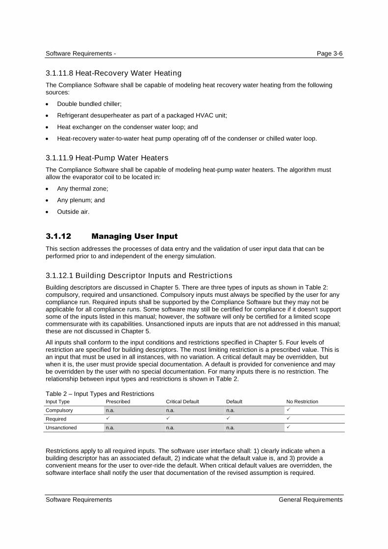
Software Requirements - Page 3-6
Software Requirements General Requirements
3.1.11.8 Heat-Recovery Water Heating
The Compliance Software shall be capable of modeling heat recovery water heating from the followingsources:
Double bundled chiller;
Refrigerant desuperheater as part of a packaged HVAC unit;
Heat exchanger on the condenser water loop; and
Heat-recovery water-to-water heat pump operating off of the condenser or chilled water loop.
3.1.11.9 Heat-Pump Water Heaters
The Compliance Software shall be capable of modeling heat-pump water heaters. The algorithm mustallow the evaporator coil to be located in:
Any thermal zone;
Any plenum; and
Outside air.
3.1.12 Managing User Input
This section addresses the processes of data entry and the validation of user input data that can beperformed prior to and independent of the energy simulation.
3.1.12.1 Building Descriptor Inputs and Restrictions
Building descriptors are discussed in Chapter 5. There are three types of inputs as shown in Table 2:compulsory, required and unsanctioned. Compulsory inputs must always be specified by the user for anycompliance run. Required inputs shall be supported by the Compliance Software but they may not beapplicable for all compliance runs. Some software may still be certified for compliance if it doesn’t supportsome of the inputs listed in this manual; however, the software will only be certified for a limited scopecommensurate with its capabilities. Unsanctioned inputs are inputs that are not addressed in this manual;these are not discussed in Chapter 5.
All inputs shall conform to the input conditions and restrictions specified in Chapter 5. Four levels ofrestriction are specified for building descriptors. The most limiting restriction is a prescribed value. This isan input that must be used in all instances, with no variation. A critical default may be overridden, butwhen it is, the user must provide special documentation. A default is provided for convenience and maybe overridden by the user with no special documentation. For many inputs there is no restriction. Therelationship between input types and restrictions is shown in Table 2.
Table 2 – Input Types and RestrictionsInput Type Prescribed Critical Default Default No Restriction
Compulsory n.a. n.a. n.a.
Required
Unsanctioned n.a. n.a. n.a.
Restrictions apply to all required inputs. The software user interface shall: 1) clearly indicate when abuilding descriptor has an associated default, 2) indicate what the default value is, and 3) provide aconvenient means for the user to over-ride the default. When critical default values are overridden, thesoftware interface shall notify the user that documentation of the revised assumption is required.

Software Requirements - Page 3-7
Software Requirements General Requirements
No restrictions are specified for unsanctioned inputs. The use of unsanctioned inputs may require anExceptional Calculation Procedure application be submitted for the building system or features.
Compliance Software may not provide default assumptions other than those specified in Chapter 5.However, the software may assist the user in describing the proposed design by displaying typical valuesfor building descriptors, provided deliberate action by the user is necessary before a displayed value isused.
3.1.12.2 Data Validation
Compulsory Input Checks
The software shall check to ensure that valid entries have been made for all compulsory buildingdescriptors before the user is permitted to proceed with the next step in the compliance process.Appendix 5.0 and Chapter 5 specify the compulsory building descriptors. Examples of compulsory inputsare climate zone, floor area, and area category classification.
Handling of Missing Inputs
If a required input is missing or invalid, the software shall: 1) notify the user that the input is missing orinvalid, 2) identify the input field(s) with missing or invalid data, and 3) prevent the user from moving tothe next step of the compliance process. The software may provide additional information designed tohelp the user correct the deficiency.
Validity Checks
The software shall check all user inputs to ensure that the following conditions are met:
Simulation Tool Limits Inputs do not exceed the minimums or maximums for the parameterspermitted by the simulation engine.
Compliance Rule Limits Inputs do not exceed minimums or maximums for the descriptors specified inChapter 5 of this document.
Simulation Tool Discrete Options Inputs correspond with valid discrete or list options for parametersavailable in the simulation engine.
Compliance Rule Discrete Options Inputs correspond with valid discrete options provided for inChapter 5.
Handling Invalid Input
When invalid data is entered, the software shall: 1) notify the user of the invalid input, 2) identify thenonconforming input field, and 3) prevent execution of the next step of the compliance run; i.e.,generating the input description for the proposed design. The software may provide additional informationdesigned to help the user correct the deficiency.
Consistency Checks
The consistency checks described above are intended to identify errors and oversights in user input andthereby help ensure that the building description is complete and interpretable by the energy analysisprogram. Examples of consistency checks include that window should not exceed the areas of wall inwhich they are contained and that the necessary plant equipment has actually been connected to thesecondary HVAC systems. The software may include additional consistency checks as needed.
Handling Inconsistent Input
If the proposed design fails a consistency check, the software shall: 1) notify the user that aninconsistency exists, 2) identify the specific consistency check that has been failed, 3) identify theinconsistent input fields, if feasible, and 4) prevent execution of the next step of the compliance process;

Software Requirements - Page 3-8
Software Requirements Special Documentation and Reporting Requirements
i.e., generating the input description for the proposed design. The software may provide additionalinformation designed to help the user correct the deficiency.
3.2 Special Documentation and Reporting Requirements
(THIS INFORMATION COULD PROBABLY BE SUMMARIZED IN A TABLE – ALL BUILDING DESCRIPTORS OF TYPE
“CRITICAL DEFAULT” REQUIRE DOCUMENTATION IF THE DEFAULT VALUE IS OVERRIDDEN. THE REPORTING
REQUIREMENTS SHOWN HERE HAVE NOT BEEN FINALIZED, BUT ARE REPRESENTATIVE OF THE TYPE OF
EXCEPTIONAL FEATURES THAT REQUIRE DOCUMENTATION.)
3.2.1 Building Envelope
3.2.1.1 Roof Radiative Properties
The user shall enter three-year aged roof reflectance and emittance for roofs that have been certified bythe Cool Roof Rating Council.
3.2.1.2 Ground Reflectance
When specific design features are incorporated to increase or reduce reflectance for the purpose ofenhancing daylighting, there can be variation between the proposed design and the standard design,when appropriately documented. In cases where the default value is overridden, the user is required tosubmit documentation identifying the test procedure that was used to establish the non-default values.
3.2.1.3 Exterior Wall Surface Properties
The default value for emittance is 0.90. The default value for reflectance is 0.30. There is no default forroughness. The default values may be overridden only in cases when the lower reflectance can bedocumented by manufacturers’ literature or tests.
3.2.2 Interior Lighting
3.2.2.1 Regulated Interior Lighting Power
Complete lighting plans and space plans are required for the tailored method. Prescriptive complianceforms for the tailored method shall be developed and these shall be verified by the plans examiner.
With the tailored lighting method, the software shall make an entry in the special features section on theCalifornia compliance forms that the tailored lighting method has been used to determine the lightingpower for this space and that all necessary prescriptive tailored lighting forms and worksheetsdocumenting the lighting and its justification shall be provided as part of the compliance documentationand be approved independently.
3.2.2.2 Indoor Lighting Power (see 5.4.4)
Compliance software shall print all applicable lighting forms and report the lighting energy use and thelighting level (Watts/ft
2) for the entire project. Compliance software shall report “No Lighting Installed” for
nonresidential spaces with no installed lighting. Compliance software shall report “Default ResidentialLighting” for residential units of high rise residential buildings and hotel/motel guest rooms.

Software Requirements - Page 3-9
Software Requirements Special Documentation and Reporting Requirements
If the modeled Lighting Power Density (LPD) is different than the actual LPD calculated from the fixtureschedule for the building, Compliance software shall model the larger of the two values for sizing themechanical systems and for the compliance run. Compliance software shall report the larger value onPERF-1. Lighting levels schedules shall be adjusted by any lighting Control Credit Watts, if input by theuser.
Lighting power is not modeled in unconditioned spaces that are modeled, but lighting in those spaces isrequired to meet the prescriptive requirements for regulated unconditioned spaces such as commercialand industrial storage spaces and parking garages. When these types of spaces are entered thecompliance software must report in the Special Features section that these spaces must comply with theprescriptive requirements for such spaces.
3.2.2.3 Design Illumination Setpoint
Spaces that have low design illuminance levels, below the ranges specified in Appendix 5.4A, shallprovide documentation that show the design illuminance to be used as the daylight illumination setpoint.
3.2.2.4 Primary and Secondary Daylighted Area
The default primary daylight area for sidelighting is a band near the window with a depth equal to thedistance from the floor to the top of the window. The default secondary daylight area for sidelighting is aband beyond the primary daylighted area that extends a distance double the distance from the floor to thetop of the window. Other daylight areas may be defined with appropriate documentation.
3.2.2.5 Light Heat Gain Distribution
Values within the ranges of Table 8 may be used when following the rules in the 2009 ASHRAE HOF.Other values may be used when manufacturers’ literature and/or testing data is available, and adequatedocumentation is provided to the California Energy Commission.
3.2.3 Exterior Lighting
If the lighted façade area exceeds exterior wall area or if door linear footage exceeds 25% of buildingperimeter, the software shall produce a warning.
3.2.4 Infiltration Data
When credit is taken for reductions in infiltration (see above), test results or research reports shall beprovided that document and support the inputs used for the baseline building and the proposed design.
3.2.5 HVAC Exceptional Conditions
3.2.5.1 Equipment Sizing
When the any proposed equipment size for secondary equipment or central plant equipment does notmatch the equipment size listed on construction documents, an exceptional condition shall be reported oncompliance forms.

Software Requirements - Page 3-10
Software Requirements Special Documentation and Reporting Requirements
3.2.5.2 Custom Occupant, Fan, Heating or Cooling Schedules
Custom hourly schedules may be used with appropriate documentation from project schedules. Thedefault schedules from Appendix 5.4B apply unless they are overridden. The user must ensure that theHVAC schedule operating hours serve all of the occupied spaces, and spaces should not be combinedwhen their weekly occupancy varies by more than 40 full load equivalent operating hours (FLEOH).
3.2.5.3 Equipment Performance Curves
(Is documentation required if non-default HVAC equipment performance curves are used? For example,COOL-CAP-FT, COOL-EIR-FT, etc.)
(Note documentation required if credits for fault detection and diagnostics and/or airflow testing aretaken.)
For equipment with a capacity less than or equal to 135,000 Btu/h, but larger than 65,000 Btu/h, the usermay not enter data on the temperature dependent equipment performance. However, the compliancesoftware vendor may work with manufacturers to collect such data and build this data into the compliancesoftware. The user may either select equipment for which the compliance software vendor has collectedor use the defaults.
3.2.5.4 Natural Ventilation
The air flow rate for the proposed design shall be determined using sound engineering methods andsupporting documentation shall be provided.
3.2.5.5 Condenser Flow Type
The default is fixed condenser flow for water-cooled condensers. If the variable-flow is selected, thesoftware must indicate that supporting documentation is required on the output forms.
3.2.5.6 Evaporative Cooling Performance Curves
User may input curves or use default curves. If defaults are overridden, the software must indicate thatsupporting documentation is required on the output forms.
3.2.5.7 Condenser Heat Recovery Effectiveness
As designed. The software must indicate that supporting documentation is required on the output forms ifheat recovery is specified.
3.2.5.8 Boiler Heat Loss
Default is 2% for electric boilers and heat-exchangers and 0% for fuel-fired boilers. If the user overridesthe default, supporting documentation is required.
3.2.5.9 Boiler Minimum Unloading Ratio
If the user does not use the default value the software must indicate that supporting documentation isrequired on the output forms.
3.2.5.10 Chiller Minimum Unloading Ratio
. If the user does not employ the default values, supporting documentation is required.
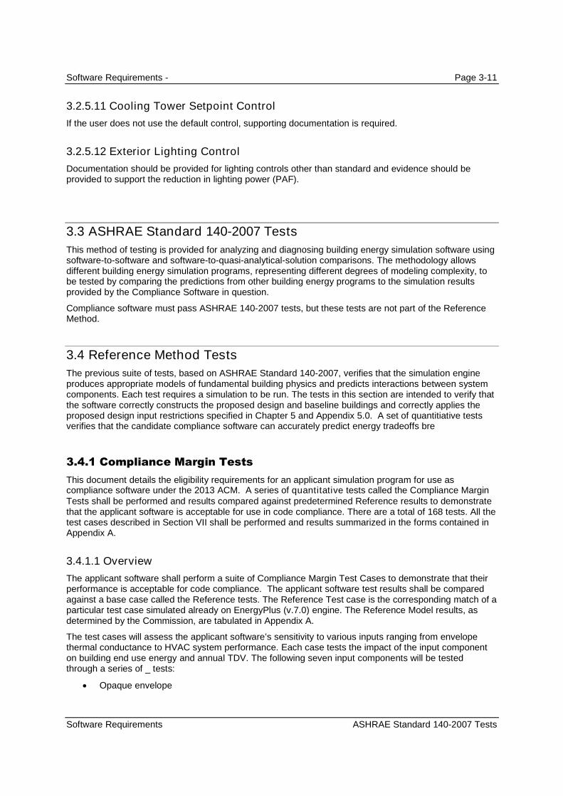
Software Requirements - Page 3-11
Software Requirements ASHRAE Standard 140-2007 Tests
3.2.5.11 Cooling Tower Setpoint Control
If the user does not use the default control, supporting documentation is required.
3.2.5.12 Exterior Lighting Control
Documentation should be provided for lighting controls other than standard and evidence should beprovided to support the reduction in lighting power (PAF).
3.3 ASHRAE Standard 140-2007 Tests
This method of testing is provided for analyzing and diagnosing building energy simulation software usingsoftware-to-software and software-to-quasi-analytical-solution comparisons. The methodology allowsdifferent building energy simulation programs, representing different degrees of modeling complexity, tobe tested by comparing the predictions from other building energy programs to the simulation resultsprovided by the Compliance Software in question.
Compliance software must pass ASHRAE 140-2007 tests, but these tests are not part of the ReferenceMethod.
3.4 Reference Method Tests
The previous suite of tests, based on ASHRAE Standard 140-2007, verifies that the simulation engineproduces appropriate models of fundamental building physics and predicts interactions between systemcomponents. Each test requires a simulation to be run. The tests in this section are intended to verify thatthe software correctly constructs the proposed design and baseline buildings and correctly applies theproposed design input restrictions specified in Chapter 5 and Appendix 5.0. A set of quantitiative testsverifies that the candidate compliance software can accurately predict energy tradeoffs bre
3.4.1 Compliance Margin Tests
This document details the eligibility requirements for an applicant simulation program for use ascompliance software under the 2013 ACM. A series of quantitative tests called the Compliance MarginTests shall be performed and results compared against predetermined Reference results to demonstratethat the applicant software is acceptable for use in code compliance. There are a total of 168 tests. All thetest cases described in Section VII shall be performed and results summarized in the forms contained inAppendix A.
3.4.1.1 Overview
The applicant software shall perform a suite of Compliance Margin Test Cases to demonstrate that theirperformance is acceptable for code compliance. The applicant software test results shall be comparedagainst a base case called the Reference tests. The Reference Test case is the corresponding match of aparticular test case simulated already on EnergyPlus (v.7.0) engine. The Reference Model results, asdetermined by the Commission, are tabulated in Appendix A.
The test cases will assess the applicant software’s sensitivity to various inputs ranging from envelopethermal conductance to HVAC system performance. Each case tests the impact of the input componenton building end use energy and annual TDV. The following seven input components will be testedthrough a series of _ tests:
Opaque envelope

Software Requirements - Page 3-12
Software Requirements Reference Method Tests
Glazing
Lighting
Daylighting
Receptacle loads
HVAC System Parameters
3.4.1.2 Reference Model
The Reference Method tests are performed on seven Prototype Models which are a subset of the DOEPrototype Building Models developed by PNNL for analysis of ASHRAE Standard 90.1. The ReferenceModels are EnergyPlus model input files of the DOE prototype models, modified to comply with therequirements of Title-24 2013. The Reference Models will be the reference baseline runs for the testcases. The applicant software shall replicate the seven building models using the same inputs as theReference Models. The models so replicated will be the applicant baseline models for the test cases.
A summary of the Reference Models is provided in Appendix A. Detailed EnergyPlus input files of theReference models are available from the California Energy Commission’s Building Energy EfficiencySoftware Consortium webpage http://www.energydataweb.com/consortium/PACdocsNR.aspx.
Reference Models used for the test cases are:
Small Office Building:
This is a single story building of area 5500 square feet with punchedwindows distributed evenly across all facades. There are five thermalzones in this building served by packaged air conditioning units. Forfurther details refer Appendix A.
Medium Office Building:
This Reference model is a three storied rectangular building with anoverall area of 53600 square feet. It has a window to wall ratio of 33%with fenestration distributed evenly across all four facades. The zones areserved by DX cooling and Gas furnace heating with electric reheat. Forfurther details refer Appendix A.
Large Office Building:
The large office building has twelve floors and a basement floor with glasswindows with a window to wall ratio of 40% on the above-grade walls. Thetotal area of the building is 498,600 square feet. The HVAC system typeused is centrifugal chillers and gas boiler. For further details referAppendix A.
Stand-Alone Retail:
The stand-alone retail is a single story rectangular building measuring178 ft by 139 ft. The total area is 24695 square feet. Windows arelocated only on the street facing façade and occupy 25.4% of thatfacade. The building is divided into five thermal zones which are servedby various system types as described in Appendix A.
Primary School:
The primary school building is a single story building with a total floorarea of 73, 960 square feet. It has a window to wall ratio of 35% withribbon windows across all facades. Thermal zoning is as per exposure
fig 1- Small Office
fig.2- Medium Office
fig.3- Large Office
fig.4- Stand-Alone Retail
fig.5- Primary School
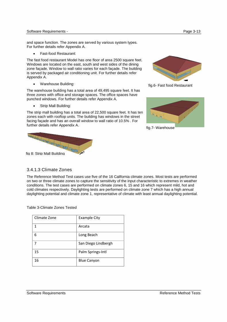
Software Requirements - Page 3-13
Software Requirements Reference Method Tests
and space function. The zones are served by various system types.For further details refer Appendix A.
Fast-food Restaurant:
The fast food restaurant Model has one floor of area 2500 square feet.Windows are located on the east, south and west sides of the diningzone façade. Window to wall ratio varies for each façade. The buildingis served by packaged air conditioning unit. For further details referAppendix A.
Warehouse Building:
The warehouse building has a total area of 49,495 square feet. It hasthree zones with office and storage spaces. The office spaces havepunched windows. For further details refer Appendix A.
Strip Mall Building:
The strip mall building has a total area of 22,500 square feet. It has tenzones each with rooftop units. The building has windows in the streetfacing façade and has an overall window to wall ratio of 10.5% . Forfurther details refer Appendix A.
3.4.1.3 Climate Zones
The Reference Method Test cases use five of the 16 California climate zones. Most tests are performedon two or three climate zones to capture the sensitivity of the input characteristic to extremes in weatherconditions. The test cases are performed on climate zones 6, 15 and 16 which represent mild, hot andcold climates respectively. Daylighting tests are performed on climate zone 7 which has a high annualdaylighting potential and climate zone 1, representative of climate with least annual daylighting potential.
Table 3-Climate Zones Tested
Climate Zone Example City
1 Arcata
6 Long Beach
7 San Diego Lindbergh
15 Palm Springs-Intl
16 Blue Canyon
fig.6- Fast food Restaurant
fig.7- Warehouse
fig 8: Strip Mall Building

Software Requirements - Page 3-14
Software Requirements Reference Method Tests
3.4.1.4 Labeling Computer Runs
Each test case used for the compliance test is labeled uniquely to make it easier to keep track of the runsand to facilitate analysis. The following scheme is used:
Envelope Test/Medium Office -CZ-15, Roof Insulation
Input Characteristic
Climate Zone
Prototype Model Type
Test Component
3.4.1.5 Test Criteria
Applicant software vendors shall perform a series of computer runs. Each of these runs shall be asystematic variation of the applicant base case model as described in Section VII. The applicant test caseresults will be compared to the reference results to verify that applicant software meets the requirementsof the ACM. Simulation results for each test case will be compiled in forms provided in Appendix A.Compiled results will include annual site energy consumption for each end-use, overall site energyconsumption, total unmet load hours and annual TDV and % variation of annual TDV and total end usesite energy.
The annual TDV % variation shall be calculated using the formula:
TDV%= (TDVb – TDVn)/TDVb
Where, TDV% is the TDV % variation,
TDVn is the annual TDV for test case number n and
TDVb is the annual TDV for the base case run.
In order to be accepted, the applicant software should fulfill the passing criteria as determined by theCommission:
For each test case,
When Reference Model TDV%r ≤ 1%, Allowed Maximum Applicant Model TDV%a =1%
When Reference Model TDV% r > 1%, Allowed Applicant Model TDV%a shall be within ± 10% of ReferenceModel TDV%r
Where, the subscript “a” represents the applicant results and “r” represents the reference results.
If any of the tests fail to meet these criteria, the applicant software will not be accepted for complianceuse.
3.4.1.6 Compliance Margin Test Cases
Test cases assess the energy impact of one or more of the building or system input characteristics on thebaseline model. Each test suite consists of a series of unique test cases aimed to test the impact of aspecific characteristic on building energy performance. Simulations are grouped according to test criteriaand sub-grouped based on the reference model type to allow for direct comparison of results. For eachtest case, the applicant software will modify the applicant baseline model with specific inputs as describedin the Test Case description section.

Software Requirements - Page 3-15
Software Requirements Reference Method Tests
The test cases are simulated on multiple California weather files to evaluate the sensitivity of the buildingor system input to extremes in climate. Results of the test case runs and the TDV percent variation overthe baseline run shall be compiled and compared against the reference results.
Each test case described in this section shall be compared against a baseline run. The baseline runs foreach of the test cases are provided in Table 4 – Baseline Runs for Test Cases. A summary of thebaseline reference Models is provided in Appendix A. Detailed EnergyPlus input files of the Referencebaseline and test case models are available from the California Energy Commission’s, Building EnergyEfficiency Software Consortium webpage http://www.energydataweb.com/consortium/PACdocsNR.aspx.
Test cases:
Envelope Test
1. Envelope Test/Medium Office-CZ-15, Roof Insulation- This case tests the impact of modifyingRoof assembly overall U value in climate zone 15. Roof assembly U value is increased 20% morethan the baseline case.
2. Envelope Test/Medium Office-CZ-15, Wall Insulation- This case tests the impact of modifyingWall assembly overall U value in climate zone 15. Wall assembly U value is modeled 20% morethan the baseline case.
3. Envelope Test/Medium Office-CZ-15, Floor Slab Insulation- This case tests the impact of aslab on grade floor with vertical perimeter insulation in climate zone 15. The baseline case hasfloor slab with no insulation.
4. Envelope Test/Medium Office-CZ-15, Infiltration- This case tests the impact of increasing theenvelope infiltration by 5% compared to baseline case in climate zone 15.
5. Envelope Test/Medium Office-CZ-16, Roof Insulation- This case tests the impact of modifyingRoof assembly overall U value in climate zone 16. Roof assembly U value is increased 20% morethan the baseline case.
6. Envelope Test/Medium Office-CZ-16, Wall Insulation- This case tests the impact of modifyingWall assembly overall U value in climate zone 15. Wall assembly U value is modeled 20% morethan the baseline case.
7. Envelope Test/Medium Office-CZ-16, Floor Slab Insulation- This case tests the impact of aslab on grade floor with vertical perimeter insulation in climate zone 15. The baseline case hasfloor slab with no insulation.
8. Envelope Test/Medium Office-CZ-16, Infiltration- This case tests the impact of increasing theenvelope infiltration by 5% compared to baseline case in climate zone 16.
9. Envelope Test/Medium Office-CZ-6, Roof Insulation- This case tests the impact of modifyingRoof assembly overall U value in climate zone 6. Roof assembly U value is increased 20% morethan the baseline case.
10. Envelope Test/Medium Office-CZ-6, Wall Insulation- This case tests the impact of modifyingWall assembly overall U value in climate zone 6. Wall assembly U value is modeled 20% morethan the baseline case.
11. Envelope Test/Medium Office-CZ-6, Floor Slab Insulation- This case tests the impact of a slabon grade floor with vertical perimeter insulation in climate zone 6. The baseline case has floorslab with no insulation.
12. Envelope Test/Medium Office-CZ-6, Infiltration- This case tests the impact of increasing theenvelope infiltration by 5% compared to baseline case in climate zone 6.
13. Envelope Test/Small Office-CZ-15, Low Sloped Roof, Solar Reflectance- This case tests theimpact of modifying the reflectivity of the roof in climate zone -15. Here, aged solar reflectance ofthe roofing product is increased by 20% compared to a low sloped base case roof.

Software Requirements - Page 3-16
Software Requirements Reference Method Tests
14. Envelope Test/Small Office-CZ-16, Low Sloped Roof, Solar Reflectance- This case tests theimpact of modifying the reflectivity of the roof in climate zone -16. Here, aged solar reflectance ofthe roofing product is increased by 20% compared to a low sloped base case roof.
15. Envelope Test/Small Office-CZ-6, Low Sloped Roof, Solar Reflectance- This case tests theimpact of modifying the reflectivity of the roof in climate zone -6. Here, aged solar reflectance ofthe roofing product is increased by 20% compared to a low sloped base case roof.
16. Envelope Test/Small Office-CZ-15, Steep Sloped Roof, Solar Reflectance- This case teststhe impact of modifying the reflectivity of the roof in climate zone -15. Here, aged solarreflectance of the roofing product is increased by 20% compared to a steep sloped base caseroof.
17. Envelope Test/Small Office-CZ-16, Steep Sloped Roof, Solar Reflectance- This case teststhe impact of modifying the reflectivity of the roof in climate zone -16. Here, aged solarreflectance of the roofing product is increased by 20% compared to a steep sloped base caseroof.
18. Envelope Test/Small Office-CZ-6, Steep Sloped Roof, Solar Reflectance- This case tests theimpact of modifying the reflectivity of the roof in climate zone -6. Here, aged solar reflectance ofthe roofing product is increased by 20% compared to a low sloped base case roof.
19. Envelope Test/Primary School-CZ-15-Heavy Construction- In this case, the impact ofenvelope mass on energy consumption in climate zone 15 is tested. The test case is modeledwith a Solid concrete wall and compared against the light weight construction baseline.
20. Envelope Test/Primary School-CZ-16-Heavy Construction- In this case, the impact ofenvelope mass on energy consumption in climate zone 16 is tested. The test case is modeledwith a Solid concrete wall and compared against the light weight construction baseline.
21. Envelope Test/Primary School-CZ-6-Heavy Construction- In this case, the impact of envelopemass on energy consumption in climate zone 6 is tested. The test case is modeled with a Solidconcrete wall and compared against the light weight construction baseline.
Envelope Glazing Test
22. Envelope Glazing Test/Medium Office-CZ-15, Window U value- This case tests the impact ofreducing the window U value by 20% compared to baseline window U value on climate zone 15.The intent is to test the sensitivity of the software to modifications in heat transmitted into thespace through fenestration.
23. Envelope Glazing Test/Medium Office-CZ-15, Window SHGC value- This case tests theimpact of reducing the window SHGC value by 20% compared to baseline SHGC on climate zone15. The intent is to test the sensitivity of the software to modifications in heat transmitted into thespace through fenestration.
24. Envelope Glazing Test/Medium Office-CZ-15, Window U & SHGC value- This case tests theimpact of reducing the window U and SHGC values by 20% compared to baseline on climatezone 15. The intent is to test the sensitivity of the software to modifications in heat transmittedinto the space through fenestration.
25. Envelope Glazing Test/Medium Office-CZ-16, Window U value- This case tests the impact ofreducing the window U value by 20% compared to baseline window U value on climate zone 16.The intent is to test the sensitivity of the software to modifications in heat transmitted into thespace through fenestration.
26. Envelope Glazing Test/Medium Office-CZ-16, Window SHGC value- This case tests theimpact of reducing the window SHGC value by 20% compared to baseline SHGC on climate zone16. The intent is to test the sensitivity of the software to modifications in heat transmitted into thespace through fenestration.
Software Requirements - Page 3-17
Software Requirements Reference Method Tests
27. Envelope Glazing Test/Medium Office-CZ-16, Window U & SHGC value- This case tests theimpact of reducing the window U and SHGC values by 20% compared to baseline on climatezone 16. The intent is to test the sensitivity of the software to modifications in heat transmittedinto the space through fenestration.
28. Envelope Glazing Test/Medium Office-CZ-6, Window U value- This case tests the impact ofreducing the window U value by 20% compared to baseline window U value on climate zone 6.The intent is to test the sensitivity of the software to modifications in heat transmitted into thespace through fenestration.
29. Envelope Glazing Test/Medium Office-CZ-6, Window SHGC value- This case tests the impactof reducing the window U value by 20% compared to baseline window U value on climate zone 6.The intent is to test the sensitivity of the software to modifications in heat transmitted into thespace through fenestration.
30. Envelope Glazing Test/Medium Office-CZ-6, Window U & SHGC value- This case tests theimpact of reducing the window U and SHGC values by 20% compared to baseline on climatezone 6. The intent is to test the sensitivity of the software to modifications in heat transmitted intothe space through fenestration.
31. Envelope Glazing Test/Large Office-CZ-7, WWR of 20%- In this case, the impact of reducingthe window to wall ratio is tested. The test case is compared against the baseline which has aWWR of 40%. This case is tested for climate zone 7.
32. Envelope Glazing Test/Large Office-CZ-7, WWR of 60%- In this case, the impact of increasingthe window to wall ratio is tested. The test case is compared against the baseline which has aWWR of 40%. This case is tested for climate zone 7.
33. Envelope Glazing Test/Large Office-CZ-7, WWR of 60% with overhang on South Façade- Inthis case, the impact of shading the south facing windows by a two feet deep overhang is tested.This case is tested for climate zone 7.
34. Envelope Glazing Test/Large Office-CZ-1, WWR of 20%- In this case, the impact of reducingthe window to wall ratio is tested. The test case is compared against the baseline which has aWWR of 40%. This case is tested for climate zone 1.
35. Envelope Glazing Test/Large Office-CZ-1, WWR of 60%- In this case, the impact of increasingthe window to wall ratio is tested. The test case is compared against the baseline which has aWWR of 40%. This case is tested for climate zone 1.
Lighting Test
36. Lighting Test/Medium Office-CZ-15, low lighting power density- This case tests the impact ofreducing the lighting power density of interior lights by 20% compared to baseline. This case istested on climate zone 15.
37. Lighting Test/Medium Office-CZ-15, high lighting power density- This case tests the impactof increasing the lighting power density of interior lights by 20% compared to baseline. This caseis tested on climate zone 15.
38. Lighting Test/Medium Office-CZ-16, low lighting power density- This case tests the impact ofreducing the lighting power density of interior lights by 20% compared to baseline. This case istested on climate zone 16.
39. Lighting Test/Medium Office-CZ-16, high lighting power density- This case tests the impactof increasing the lighting power density of interior lights by 20% compared to baseline. This caseis tested on climate zone 16.
40. Lighting Test/Medium Office-CZ-6, low lighting power density- This case tests the impact ofreducing the lighting power density of interior lights by 20% compared to baseline. This case istested on climate zone 6.

Software Requirements - Page 3-18
Software Requirements Reference Method Tests
41. Lighting Test/Medium Office-CZ-6, high lighting power density- This case tests the impact ofincreasing the lighting power density of interior lights by 20% compared to baseline. This case istested on climate zone 6.
Daylighting Test
42. Daylighting Test/Large Office-CZ-7, Daylight sensors with Continuous Dimming- This casetests the impact of daylighting. Daylight sensors with continuous dimming is modeled in a largeoffice building type with a WWR of 40% and results compared against Large office Prototypemodel , both modeled for climate zone 7.
43. Daylighting Test/Large Office-CZ-7, Daylight sensors with Continuous Dimming andwindows with high VT- This case tests the impact of daylighting. Daylight sensors withcontinuous dimming are modeled in a large office building type with a WWR of 40%. The visibletransmittance of windows is increased to improve the daylighting potential. This case is tested onlarge office Prototype model, both modeled for climate zone 7.
44. Daylighting Test/Large Office-CZ-7, Daylight sensors with Stepped Dimming- This casetests the impact of daylighting. Daylight sensors with stepped dimming is modeled in a largeoffice building type with a WWR of 40% and results compared against Large office Prototypemodel, both modeled for climate zone 7.
45. Daylighting Test/Large Office-CZ-7, Daylight sensors with Stepped Dimming and windowswith high VT- This case tests the impact of daylighting. Daylight sensors with stepped dimmingare modeled in a large office building type with a WWR of 40%. The visible transmittance ofwindows is increased to improve the daylighting potential. This case is tested on large officePrototype model, both modeled for climate zone 7.
46. Daylighting Test/Large Office-CZ-7,WWR of 20%, Daylight sensors with ContinuousDimming- This case tests the impact of daylighting. Daylight sensors with continuous dimming ismodeled in a large office building type with a WWR of 20% and results compared against Largeoffice Prototype model , both modeled for climate zone 7.
47. Daylighting Test/Large Office-CZ-7, WWR of 20%, Daylight sensors with ContinuousDimming and windows with high VT--This case tests the impact of daylighting. Daylightsensors with continuous dimming are modeled in a large office building type with a WWR of 20%.The visible transmittance of windows is increased to improve the daylighting potential. This caseis tested on large office Prototype model in climate zone 7.
48. Daylighting Test/Large Office-CZ-7, WWR of 20%, Daylight sensors with Stepped Dimming-This case tests the impact of daylighting. Daylight sensors with stepped dimming is modeled in alarge office building type with a WWR of 20% and results compared against Large officePrototype model in climate zone 7.
49. Daylighting Test/Large Office-CZ-7, WWR of 20%, Daylight sensors with Stepped Dimmingand windows with high VT- This case tests the impact of daylighting. Daylight sensors withstepped dimming are modeled in a large office building type with a WWR of 20%. The visibletransmittance of windows is increased to improve the daylighting potential. This case is tested onlarge office Prototype model in climate zone 7.
50. Daylighting Test/Large Office-CZ-7,WWR of 60%, Daylight sensors with ContinuousDimming- This case tests the impact of daylighting. Daylight sensors with continuous dimming ismodeled in a large office building type with a WWR of 60% and results compared against Largeoffice Prototype model in climate zone 7.
51. Daylighting Test/Large Office-CZ-7, WWR of 60%, Daylight sensors with ContinuousDimming and windows with high VT- This case tests the impact of daylighting. Daylightsensors with continuous dimming are modeled in a large office building type with a WWR of 60%.The visible transmittance of windows is increased to improve the daylighting potential. This caseis tested on large office Prototype model in climate zone 7.

Software Requirements - Page 3-19
Software Requirements Reference Method Tests
52. Daylighting Test/Large Office-CZ-7, WWR of 60%, Daylight sensors with Stepped Dimming-This case tests the impact of daylighting. Daylight sensors with stepped dimming is modeled in alarge office building type with a WWR of 60% and results compared against Large officePrototype model in climate zone 7.
53. Daylighting Test/Large Office-CZ-7, WWR of 60%, Daylight sensors with Stepped Dimmingand windows with high VT- This case tests the impact of daylighting. Daylight sensors withstepped dimming are modeled in a large office building type with a WWR of 60%. The visibletransmittance of windows is increased to improve the daylighting potential. This case is tested onlarge office Prototype model in climate zone 7.
54. Daylighting Test/Large Office-CZ-1, Daylight sensors with Continuous Dimming- This casetests the impact of daylighting. Daylight sensors with continuous dimming is modeled in a largeoffice building type with a WWR of 40% and results compared against Large office Prototypemodel , both modeled for climate zone 1.
55. Daylighting Test/Large Office-CZ-1, Daylight sensors with Continuous Dimming andwindows with high VT- This case tests the impact of daylighting. Daylight sensors withcontinuous dimming are modeled in a large office building type with a WWR of 40%. The visibletransmittance of windows is increased to improve the daylighting potential. This case is tested onlarge office Prototype model, both modeled for climate zone 1.
56. Daylighting Test/Large Office-CZ-1, Daylight sensors with Stepped Dimming- This casetests the impact of daylighting. Daylight sensors with stepped dimming is modeled in a largeoffice building type with a WWR of 40% and results compared against Large office Prototypemodel , both modeled for climate zone 1.
57. Daylighting Test/Large Office-CZ-1, Daylight sensors with Stepped Dimming and windowswith high VT- This case tests the impact of daylighting. Daylight sensors with stepped dimmingare modeled in a large office building type with a WWR of 40%. The visible transmittance ofwindows is increased to improve the daylighting potential. This case is tested on large officePrototype model, both modeled for climate zone 1.
58. Daylighting Test/Large Office-CZ-1,WWR of 20%, Daylight sensors with ContinuousDimming- This case tests the impact of daylighting. Daylight sensors with continuous dimming ismodeled in a large office building type with a WWR of 20% and results compared against Largeoffice Prototype model , both modeled for climate zone 1.
59. Daylighting Test/Large Office-CZ-1, WWR of 20%, Daylight sensors with ContinuousDimming and windows with high VT--This case tests the impact of daylighting. Daylightsensors with continuous dimming are modeled in a large office building type with a WWR of 20%.The visible transmittance of windows is increased to improve the daylighting potential. This caseis tested on large office Prototype model in climate zone 1.
60. Daylighting Test/Large Office-CZ-1, WWR of 20%, Daylight sensors with Stepped Dimming-This case tests the impact of daylighting. Daylight sensors with stepped dimming is modeled in alarge office building type with a WWR of 20% and results compared against Large officePrototype model in climate zone 1.
61. Daylighting Test/Large Office-CZ-1, WWR of 20%, Daylight sensors with Stepped Dimmingand windows with high VT- This case tests the impact of daylighting. Daylight sensors withstepped dimming are modeled in a large office building type with a WWR of 20%. The visibletransmittance of windows is increased to improve the daylighting potential. This case is tested onlarge office Prototype model in climate zone 1.
62. Daylighting Test/Large Office-CZ-1 ,WWR of 60%, Daylight sensors with ContinuousDimming- This case tests the impact of daylighting. Daylight sensors with continuous dimming ismodeled in a large office building type with a WWR of 60% and results compared against Largeoffice Prototype model in climate zone 1.

Software Requirements - Page 3-20
Software Requirements Reference Method Tests
63. Daylighting Test/Large Office-CZ-1, WWR of 60%, Daylight sensors with ContinuousDimming and windows with high VT- This case tests the impact of daylighting. Daylightsensors with continuous dimming are modeled in a large office building type with a WWR of 60%.The visible transmittance of windows is increased to improve the daylighting potential. This caseis tested on large office Prototype model in climate zone 1.
64. Daylighting Test/Large Office-CZ-1, WWR of 60%, Daylight sensors with Stepped Dimming-This case tests the impact of daylighting. Daylight sensors with stepped dimming is modeled in alarge office building type with a WWR of 60% and results compared against Large officePrototype model in climate zone 1.
65. Daylighting Test/Large Office-CZ-1, WWR of 60%, Daylight sensors with Stepped Dimmingand windows with high VT- This case tests the impact of daylighting. Daylight sensors withstepped dimming are modeled in a large office building type with a WWR of 60%. The visibletransmittance of windows is increased to improve the daylighting potential. This case is tested onlarge office Prototype model in climate zone 1.
66. Daylighting Test/Stand Alone Retail-CZ-7, with skylights with high VT- In this case theimpact of daylighting with skylights is tested. Daylight potential is improved by increasing thevisible transmittance of the skylight glass. Standalone retail building in climate zone 7 is tested inthis case.
67. Daylighting Test/Stand Alone Retail-CZ-7, with SRR of 5%- In this case the impact ofdaylighting with skylights is tested. Daylight potential is improved by increasing the SRR to 5%compared to baseline SRR of 1.3%. Standalone retail building in climate zone 7 is tested in thiscase.
68. Daylighting Test/Stand Alone Retail-CZ-7, with SRR of 5% and skylights with high VT - Inthis case the impact of daylighting with skylights is tested. Daylight potential is improved byincreasing the SRR to 5% compared to baseline SRR of 1.3%, and visible transmittance ofskylight glass. Standalone retail building in climate zone 7 is tested in this case.
69. Daylighting Test/Stand Alone Retail-CZ-1, with skylights with high VT-- In this case theimpact of daylighting with skylights is tested. Daylight potential is improved by increasing thevisible transmittance of the skylight glass. Standalone retail building in climate zone 1 is tested inthis case.
70. Daylighting Test/Stand Alone Retail-CZ-1, with SRR of 5%-%- In this case the impact ofdaylighting with skylights is tested. Daylight potential is improved by increasing the SRR to 5%compared to baseline SRR of 1.3%. Standalone retail building in climate zone 1 is tested in thiscase.
71. Daylighting Test/Stand Alone Retail-CZ-1, with SRR of 5% and skylights with high VT - Inthis case the impact of daylighting with skylights is tested. Daylight potential is improved byincreasing the SRR to 5% compared to baseline SRR of 1.3%, and visible transmittance ofskylight glass. Standalone retail building in climate zone 1 is tested in this case.
Equipment Test
72. Equipment Test/Medium Office-CZ-15, with low Equipment Power Density- This case teststhe impact of reducing the equipment power density by 20% compared to baseline. This case istested on climate zone 15.
73. Equipment Test/Medium Office-CZ-15, with high Equipment Power Density- This case teststhe impact of increasing the equipment power density by 20% compared to baseline. This case istested on climate zone 15.
74. Equipment Test/Medium Office-CZ-16, with low Equipment Power Density- This case teststhe impact of reducing the equipment power density by 20% compared to baseline. This case istested on climate zone 16.

Software Requirements - Page 3-21
Software Requirements Reference Method Tests
75. Equipment Test/Medium Office-CZ-16, with high Equipment Power Density- This case teststhe impact of increasing the equipment power density by 20% compared to baseline. This case istested on climate zone 16.
76. Equipment Test/Medium Office-CZ-6, with low Equipment Power Density- This case teststhe impact of reducing the equipment power density by 20% compared to baseline. This case istested on climate zone 6.
77. Equipment Test/Medium Office-CZ-6, with high Equipment Power Density- This case teststhe impact of increasing the equipment power density by 20% compared to baseline. This case istested on climate zone 6.
78. Equipment Test/Fast food Restaurant-CZ-6, with high Process Load- This case tests theimpact of increasing the electric process load by 5% compared to baseline. This case is tested onclimate zone 6.
The System test suit comprises of test cases for 12 different HVAC system types like:
o Packaged Terminal Air Conditioner
o Packaged Terminal Heat Pump
o Packaged Single Zone System
o Packaged VAV System
o Single duct built-up VAV system
o Fan coil units
o Water loop heat pump
o Evaporative cooling system
o Natural ventilation
o Hydronic radiant system
o Under-floor air distribution system
o Variable refrigerant flow (VRF) system
HVAC Test Cases
79. HVAC Test /PTAC, Stripmall-CZ-6, Low Efficiency- This case tests the impact of modifying aset of parameters with efficiencies and requirements lower than the 2008 Title 24 baseline.
80. HVAC Test /PTAC, Stripmall-CZ-6, High Efficiency- This case tests the impact of modifying aset of parameters with efficiencies and requirements higher than the 2008 Title 24 baseline.
81. HVAC Test /PTAC, Stripmall-CZ-15, Low Efficiency- This case tests the impact of modifying aset of parameters with efficiencies and requirements lower than the 2008 Title 24 baseline.
82. HVAC Test /PTAC, Stripmall-CZ-15, High Efficiency- This case tests the impact of modifying aset of parameters with efficiencies and requirements higher than the 2008 Title 24 baseline.
83. HVAC Test /PTAC, Stripmall-CZ-16, Low Efficiency- This case tests the impact of modifying aset of parameters with efficiencies and requirements lower than the 2008 Title 24 baseline.
84. HVAC Test /PTAC, Stripmall-CZ-16, High Efficiency- This case tests the impact of modifying aset of parameters with efficiencies and requirements higher than the 2008 Title 24 baseline.
85. HVAC Test /PTHP, Stripmall-CZ-6, Low Efficiency- This case tests the impact of modifying aset of parameters with efficiencies and requirements lower than the 2008 Title 24 baseline.
86. HVAC Test /PTHP, Stripmall-CZ-6, High Efficiency- This case tests the impact of modifying aset of parameters with efficiencies and requirements higher than the 2008 Title 24 baseline.

Software Requirements - Page 3-22
Software Requirements Reference Method Tests
87. HVAC Test /PTHP, Stripmall-CZ-15, Low Efficiency- This case tests the impact of modifying aset of parameters with efficiencies and requirements lower than the 2008 Title 24 baseline.
88. HVAC Test /PTHP, Stripmall-CZ-15, High Efficiency- This case tests the impact of modifying aset of parameters with efficiencies and requirements higher than the 2008 Title 24 baseline.
89. HVAC Test /PTHP, Stripmall-CZ-16, Low Efficiency- This case tests the impact of modifying aset of parameters with efficiencies and requirements lower than the 2008 Title 24 baseline.
90. HVAC Test /PTHP, Stripmall-CZ-16, High Efficiency- This case tests the impact of modifying aset of parameters with efficiencies and requirements higher than the 2008 Title 24 baseline.
91. HVAC Test/ PSZ, Stripmall-CZ-6, Low Efficiency- This case tests the impact of modifying a setof parameters with efficiencies and requirements lower than the 2008 Title 24 baseline.
92. HVAC Test/ PSZ, Stripmall-CZ-6, High Efficiency- This case tests the impact of modifying a setof parameters with efficiencies and requirements higher than the 2008 Title 24 baseline.
93. HVAC Test/ PSZ, Stripmall-CZ-15, Low Efficiency- This case tests the impact of modifying aset of parameters with efficiencies and requirements lower than the 2008 Title 24 baseline.
94. HVAC Test/ PSZ, Stripmall-CZ-15, High Efficiency- This case tests the impact of modifying aset of parameters with efficiencies and requirements higher than the 2008 Title 24 baseline.
95. HVAC Test/ PSZ, Stripmall-CZ-16, Low Efficiency- This case tests the impact of modifying aset of parameters with efficiencies and requirements lower than the 2008 Title 24 baseline.
96. HVAC Test/ PSZ, Stripmall-CZ-16, High Efficiency- This case tests the impact of modifying aset of parameters with efficiencies and requirements higher than the 2008 Title 24 baseline.
97. HVAC Test/PVAV, Medium Office-CZ-6, Low Efficiency- This case tests the impact ofmodifying a set of parameters with efficiencies and requirements lower than the 2008 Title 24baseline.
98. HVAC Test/PVAV, Medium Office-CZ-6, High Efficiency- This case tests the impact ofmodifying a set of parameters with efficiencies and requirements higher than the 2008 Title 24baseline.
99. HVAC Test/PVAV, Medium Office-CZ-15, Low Efficiency- This case tests the impact ofmodifying a set of parameters with efficiencies and requirements lower than the 2008 Title 24baseline.
100. HVAC Test/PVAV, Medium Office-CZ-15, High Efficiency- This case tests the impactof modifying a set of parameters with efficiencies and requirements higher than the 2008 Title 24baseline.
101. HVAC Test/PVAV, Medium Office-CZ-16, Low Efficiency- This case tests the impact ofmodifying a set of parameters with efficiencies and requirements lower than the 2008 Title 24baseline.
102. HVAC Test/PVAV, Medium Office-CZ-16, High Efficiency- This case tests the impactof modifying a set of parameters with efficiencies and requirements higher than the 2008 Title 24baseline.
103. HVAC Test /VAV, Large Office-CZ-6, Low Efficiency- This case tests the impact ofmodifying a set of parameters with efficiencies and requirements lower than the 2008 Title 24baseline.
104. HVAC Test /VAV, Large Office-CZ-6, High Efficiency- This case tests the impact ofmodifying a set of parameters with efficiencies and requirements higher than the 2008 Title 24baseline.

Software Requirements - Page 3-23
Software Requirements Reference Method Tests
105. HVAC Test /VAV, Large Office-CZ-15, Low Efficiency- This case tests the impact ofmodifying a set of parameters with efficiencies and requirements lower than the 2008 Title 24baseline.
106. HVAC Test /VAV, Large Office-CZ-15, High Efficiency- This case tests the impact ofmodifying a set of parameters with efficiencies and requirements higher than the 2008 Title 24baseline.
107. HVAC Test /VAV, Large Office-CZ-16, Low Efficiency- This case tests the impact ofmodifying a set of parameters with efficiencies and requirements lower than the 2008 Title 24baseline.
108. HVAC Test /VAV, Large Office-CZ-16, High Efficiency- This case tests the impact ofmodifying a set of parameters with efficiencies and requirements higher than the 2008 Title 24baseline.
109. HVAC Test/FanCoil, Stripmall-CZ-6, Low Efficiency- This case tests the impact ofmodifying a set of parameters with efficiencies and requirements lower than the 2008 Title 24baseline.
110. HVAC Test/FanCoil, Stripmall-CZ-6, High Efficiency- This case tests the impact ofmodifying a set of parameters with efficiencies and requirements higher than the 2008 Title 24baseline.
111. HVAC Test/FanCoil, Stripmall-CZ-15, Low Efficiency- This case tests the impact ofmodifying a set of parameters with efficiencies and requirements lower than the 2008 Title 24baseline.
112. HVAC Test/FanCoil, Stripmall-CZ-15, High Efficiency- This case tests the impact ofmodifying a set of parameters with efficiencies and requirements higher than the 2008 Title 24baseline.
113. HVAC Test/FanCoil, Stripmall-CZ-16, Low Efficiency- This case tests the impact ofmodifying a set of parameters with efficiencies and requirements lower than the 2008 Title 24baseline.
114. HVAC Test/FanCoil, Stripmall-CZ-16, High Efficiency- This case tests the impact ofmodifying a set of parameters with efficiencies and requirements higher than the 2008 Title 24baseline.
115. HVAC Test/VRF , Stripmall-CZ-6, Low Efficiency- This case tests the impact ofmodifying a set of parameters with efficiencies and requirements lower than the 2008 Title 24baseline.
116. HVAC Test/VRF, Stripmall-CZ-6, High Efficiency- This case tests the impact ofmodifying a set of parameters with efficiencies and requirements higher than the 2008 Title 24baseline.
117. HVAC Test/VRF , Stripmall-CZ-15, Low Efficiency- This case tests the impact ofmodifying a set of parameters with efficiencies and requirements lower than the 2008 Title 24baseline.
118. HVAC Test/VRF, Stripmall-CZ-15, High Efficiency- This case tests the impact ofmodifying a set of parameters with efficiencies and requirements higher than the 2008 Title 24baseline.
119. HVAC Test/VRF , Stripmall-CZ-16, Low Efficiency- This case tests the impact ofmodifying a set of parameters with efficiencies and requirements lower than the 2008 Title 24baseline.
120. HVAC Test/VRF, Stripmall-CZ-16, High Efficiency- This case tests the impact ofmodifying a set of parameters with efficiencies and requirements higher than the 2008 Title 24baseline.

Software Requirements - Page 3-24
Software Requirements Reference Method Tests
Table 4 – Baseline Runs for Test Cases
TestCaseNo.
Test Case Baseline Model
1 Envelope Test Medium OfficeCZ-15 Roof Insulation
Medium Office CZ-15 Baseline
2 Envelope Test Medium OfficeCZ-15 Wall Insulation
3Envelope Test Medium OfficeCZ-15 Floor SlabInsulation
4 Envelope Test Medium OfficeCZ-15 Infiltration
5 Envelope Test Medium OfficeCZ-16 Roof Insulation
Medium Office CZ-16 Baseline
6 Envelope Test Medium OfficeCZ-16 Wall Insulation
7Envelope Test Medium OfficeCZ-16 Floor SlabInsulation
8 Envelope Test Medium OfficeCZ-16 Infiltration
9 Envelope Test Medium OfficeCZ-6 Roof Insulation
Medium Office CZ-6 Baseline10 Envelope Test Medium OfficeCZ-6 Wall Insulation
11 Envelope Test Medium OfficeCZ-6 Floor Slab Insulation
12 Envelope Test Medium OfficeCZ-6 Infiltration
13Envelope Test Small OfficeCZ-15 SolarReflectance-LowSlope
Small Office CZ-15 SolarReflectance-LowSlope Baseline
14Envelope Test Small OfficeCZ-16 SolarReflectance-LowSlope
Small Office CZ-16 SolarReflectance-LowSlope Baseline
15Envelope Test Small OfficeCZ-6 SolarReflectance-LowSlope
Small Office CZ-6 SolarReflectance-LowSlope Baseline
16Envelope Test Small OfficeCZ-15 SolarReflectance-Steep Slope
Small Office CZ-15 SolarReflectance-SteepSlope Baseline
17Envelope Test Small OfficeCZ-16 SolarReflectance-Steep Slope
Small Office CZ-16 SolarReflectance-SteepSlope Baseline
18Envelope Test Small OfficeCZ-6 SolarReflectance-Steep Slope
Small Office CZ-6 SolarReflectance-SteepSlope Baseline
19 Envelope Test Primary SchoolCZ-15 Heavy Envelope Test Primary SchoolCZ-15 Light
20 Envelope Test Primary SchoolCZ-16 Heavy Envelope Test Primary SchoolCZ-16 Light
21 Envelope Test Primary SchoolCZ-6 Heavy Envelope Test Primary SchoolCZ-6 Light
22 Envelope Glazing Test Medium OfficeCZ-15 Window U
Medium Office CZ-15 Baseline23
Envelope Glazing Test Medium OfficeCZ-15 WindowSHGC
24Envelope Glazing Test Medium OfficeCZ-15 WindowU&SHGC
25 Envelope Glazing Test Medium OfficeCZ-16 Window U
Medium Office CZ-16 Baseline26
Envelope Glazing Test Medium OfficeCZ-16 WindowSHGC
27Envelope Glazing Test Medium OfficeCZ-16 WindowU&SHGC

Software Requirements - Page 3-25
Software Requirements Reference Method Tests
28 Envelope Glazing Test Medium OfficeCZ-6 Window U
Medium Office CZ-6 Baseline29
Envelope Glazing Test Medium OfficeCZ-6 WindowSHGC
30Envelope Glazing Test Medium OfficeCZ-6 WindowU&SHGC
31 Envelope Glazing Test Large OfficeCZ-7 WWR 20%
Large Office CZ-7 Baseline
32 Envelope Glazing Test Large OfficeCZ-7 WWR 60%
33Envelope Glazing Test Large OfficeCZ-7 WWR 60%with South overhang
34 Envelope Glazing Test Large OfficeCZ-1 WWR 20%
35 Envelope Glazing Test Large OfficeCZ-1 WWR 60%
36 Lighting Tests Medium OfficeCZ-15 low LPDMedium Office CZ-15 Baseline
37 Lighting Tests Medium OfficeCZ-15 high LPD
38 Lighting Tests Medium OfficeCZ-16 low LPDMedium Office CZ-16 Baseline
39 Lighting Tests Medium OfficeCZ-16 high LPD
40 Lighting Tests Medium OfficeCZ-6 low LPDMedium Office CZ-6 Baseline
41 Lighting Tests Medium OfficeCZ-6 high LPD
42Daylighting Tests Large OfficeCZ-7 ContinuousDimming
Large Office CZ-7 Baseline43
Daylighting Tests Large OfficeCZ-7 ContinuousDimming and high VT
44 Daylighting Tests Large OfficeCZ-7 Stepped Dimming
45Daylighting Tests Large OfficeCZ-7 Stepped Dimmingand high VT
46Daylighting Tests Large OfficeCZ-7 WWR-20%,Continuous Dimming
Large Office CZ-7 WWR 20% Baseline
47Daylighting Tests Large OfficeCZ-7 WWR-20%,Continuous Dimming and high VT
48Daylighting Tests Large OfficeCZ-7 WWR-20%,SteppedDimming
49Daylighting Tests Large OfficeCZ-7 WWR-20%,SteppedDimming and high VT
50Daylighting Tests Large OfficeCZ-7WWR-60%,Continuous Dimming
Large Office CZ-7 WWR 60% Baseline
51Daylighting Tests Large OfficeCZ-7 WWR-60%,Continuous Dimming and high VT
52Daylighting Tests Large OfficeCZ-7 WWR-60%,SteppedDimming
53Daylighting Tests Large OfficeCZ-7 WWR-60%,SteppedDimming and high VT
54Daylighting Tests Large OfficeCZ-1 ContinuousDimming
Large Office CZ-1 Baseline

Software Requirements - Page 3-26
Software Requirements Reference Method Tests
55Daylighting Tests Large OfficeCZ-1 ContinuousDimming and high VT
56 Daylighting Tests Large OfficeCZ-1 Stepped Dimming
57Daylighting Tests Large OfficeCZ-1 Stepped Dimmingand high VT
58Daylighting Tests Large OfficeCZ-1 WWR-20%,Continuous Dimming
Large Office CZ-1 WWR-20% Baseline
59Daylighting Tests Large OfficeCZ-1 WWR-20%,Continuous Dimming and high VT
60Daylighting Tests Large OfficeCZ-1 WWR-20%,SteppedDimming
61Daylighting Tests Large OfficeCZ-1 WWR-20%,SteppedDimming and high VT
62Daylighting Tests Large OfficeCZ-1WWR-60%,Continuous Dimming
Large Office CZ-1 WWR-60% Baseline
63Daylighting Tests Large OfficeCZ-1 WWR-60%,Continuous Dimming and high VT
64Daylighting Tests Large OfficeCZ-1 WWR-60%,SteppedDimming
65Daylighting Tests Large OfficeCZ-1 WWR-60%,SteppedDimming and high VT
66 Daylighting Tests Stand Alone Retail CZ-7 Skylight VT
Stand Alone Retail CZ-7 Baseline67 Daylighting Tests Stand Alone Retail CZ-7 SRR-5%
68Daylighting Tests Stand Alone Retail CZ-7 SRR-5% andhigh VT
69 Daylighting Tests Stand Alone Retail CZ-1 Skylight VT
Stand Alone Retail CZ-1 Baseline70 Daylighting Tests Stand Alone Retail CZ-1 SRR-5%
71Daylighting Tests Stand Alone Retail CZ-1 SRR-5% andhigh VT
72 Equipment test Medium OfficeCZ-15 low EPDMedium Office CZ-15 Baseline
73 Equipment test Medium OfficeCZ-15 high EPD
74 Equipment test Medium OfficeCZ-16 low EPDMedium Office CZ-16 Baseline
75 Equipment test Medium OfficeCZ-16 high EPD
76 Equipment test Medium OfficeCZ-6 low EPDMedium Office CZ-6 Baseline
77 Equipment test Medium OfficeCZ-6 high EPD
78Equipment test Fast food RestaurantCZ-6 high Processload
Fast food Restaurant CZ-6 Baseline
79 PTAC Test Strip Mall CZ-6 Low Eff PTAC Strip Mall CZ-6 Baseline
80 PTAC Test Strip Mall CZ-6 High Eff
81 PTAC Test Strip Mall CZ-15 Low Eff PTAC Strip Mall CZ-15 Baseline

Software Requirements - Page 3-27
Software Requirements Reference Method Tests
82 PTAC Test Strip Mall CZ-15 High Eff
83 PTAC Test Strip Mall CZ-16 Low Eff PTAC Strip Mall CZ-16 Baseline
84 PTAC Test Strip Mall CZ-16 High Eff
85 PTHP Test Strip Mall CZ-6 Low Eff PTHP Strip Mall CZ-6 Baseline
86 PTHP Test Strip Mall CZ-6 High Eff
87 PTHP Test Strip Mall CZ-15 Low Eff PTHP Strip Mall CZ-15 Baseline
88 PTHP Test Strip Mall CZ-15 High Eff
89 PTHP Test Strip Mall CZ-16 Low Eff PTHP Strip Mall CZ-16 Baseline
90 PTHP Test Strip Mall CZ-16 High Eff
91 PSZ Test Strip Mall CZ-6 Low Eff PSZ Strip Mall CZ-6 Baseline
92 PSZ Test Strip Mall CZ-6 High Eff
93 PSZ Test Strip Mall CZ-15 Low Eff PSZ Strip Mall CZ-15 Baseline
94 PSZ Test Strip Mall CZ-15 High Eff
95 PSZ Test Strip Mall CZ-16 Low Eff PSZ Strip Mall CZ-16 Baseline
96 PSZ Test Strip Mall CZ-16 High Eff
97 PVAV Test Medium Office CZ-6 Low Eff PVAV Medium Office CZ-6 Baseline
98 PVAV Test Medium Office CZ-6 High Eff
99 PVAV Test Medium Office CZ-15 Low Eff PVAV Medium Office CZ-15 Baseline
100 PVAV Test Medium Office CZ-15 High Eff
101 PVAV Test Medium Office CZ-16 Low Eff PVAV Medium Office CZ-16 Baseline
102 PVAV Test Medium Office CZ-16 High Eff
103 VAV Test Large Office CZ-6 Low Eff VAV Large Office CZ-6 Baseline
104 VAV Test Large Office CZ-6 Low Eff
105 VAV Test Large Office CZ-15 Low Eff VAV Large Office CZ-15 Baseline
106 VAV Test LargeOffice CZ-15 Low Eff
107 VAV Test LargeOffice CZ-16 Low Eff VAV Large Office CZ-16 Baseline
108 VAV Test LargeOffice CZ-16 Low Eff
109 FanCoil Test Strip Mall CZ-6 Low Eff FanCoil Strip Mall CZ-6 Baseline
110 FanCoil Test Strip Mall CZ-6 High Eff
111 FanCoil Test Strip Mall CZ-15 Low Eff FanCoil Strip Mall CZ-15 Baseline
112 FanCoil Test Strip Mall CZ-15 High Eff
113 FanCoil Test Strip Mall CZ-16 Low Eff FanCoil Strip Mall CZ-16 Baseline
114 FanCoil Test Strip Mall CZ-16 High Eff
115 VRF Test Strip Mall CZ-6 Low Eff PSZ Strip Mall CZ-6 Baseline
116 VRF Test Strip Mall CZ-6 High Eff
117 VRF Test Strip Mall CZ-15 Low Eff PSZ Strip Mall CZ-15 Baseline
118 VRF Test Strip Mall CZ-15 High Eff
119 VRF Test Strip Mall CZ-16 Low Eff PSZ Strip Mall CZ-16 Baseline

Software Requirements - Page 3-28
Software Requirements Reference Method Tests
120 VRF Test Strip Mall CZ-16 High Eff
3.4.1.7 Results Documentation
The applicant shall perform simulations for all tests specified in Section VII and report results in the formsprovided in Appendix A.
3.4.2 Ruleset Implementation Tests
The Compliance Margin Tests in the Reference Method suite of tests verifies that the simulation engineproduces results that are within an acceptable range. The tests in this section are intended to verify thatthe software correctly constructs the baseline model and applies rules of the 2013 Nonresidential ACMappropriately to the proposed and baseline models. Evaluation of the modeling assumptions and baselinebuilding tests is qualitative.
3.4.2.1 Overview
The test runs described in this section represent the Title-24 2013 Non-Residential ACM code compliancecalculation and use the following Prototype Models- Small Office Building, Medium Office Building, LargeOffice Building, Warehouse Building and Small Hotel. For further details on the Prototype Models, refer toSection III of the Software Compliance Specification document. Each of the baseline test cases shall becreated by modifying the Prototype Model as described in Section IV of this document. The modifiedPrototype Model shall form the proposed case for each test run. The baseline model shall be generatedby compliance software as per the rules in the 2013 Nonresidential ACM. The baseline and proposedmodel files for each of test cases shall then be evaluated to verify that:
The baseline building envelope constructions are correctly substituted for exterior opaque surfacesand fenestrations.
Fenestration area in the baseline building is reduced in accordance with the 2013 NonresidentialACM Manual, when the proposed design fenestration area is greater than 40% of the exterior wall.
Skylight area in the baseline building is adjusted in accordance with the 2013 Nonresidential ACMManual, when applicable.
Default schedules of operation are applied for both the baseline building and the proposed design.
The proposed and baseline cases use the same defaults or tailored inputs for internal loads asrequired by the 2013 Nonresidential ACM Manual.
The baseline building lighting system is correctly specified and that exterior lighting is modeled.
Receptacle loads, process loads is modeled according to the rules in the 2013 Nonresidential ACMManual.
The baseline building use the correct system types as prescribed in Table_ of the 2013Nonresidential ACM Manual.
An economizer (of the right type) is included in the baseline building if required.
The primary and secondary baseline building systems are properly specified and sized.
Fan brake horsepower is correctly specified for the baseline building.
Prescribed modeling assumptions are applied for both the baseline building and the proposed design.

Software Requirements - Page 3-29
Software Requirements Reference Method Tests
Overhangs are modeled in the proposed design for Run 7 but not the baseline building.
Unconditioned spaces are modeled.
Other baseline building specifications and/or modeling assumptions are correctly applied.
As the software developer verifies the above and other conditions, the input and output files should beannotated with comments or other methods to demonstrate that the modeling rules specified in the 2013Nonresidential ACM Manual are correctly applied. Software developers should use the output formatspreadsheets, included in Appendix B, to report the results of these tests. These annotated files shallthen be submitted to the Commission for further evaluation. Any errors discovered shall be corrected bymaking modifications to the software; the runs shall be repeated; and the new results shall be annotatedfor submittal to the Commission.
3.4.2.2 Labeling of Baseline Tests
The Baseline Tests are labeled using the format:
Baseline Fenestration Test/Medium Office -CZ-15, Exterior Envelope Run 01
Run name number
Climate Zone
Prototype Model Type
Test Type
3.4.2.3 Rule set Implementation Tests
The following tests shall be performed to verify that the compliance software correctly creates thebaseline model and applies modeling rules as per the requirements of the Nonresidential ACM 2013. Theproposed model shall be created by modifying the appropriate Prototype Model type. The Baseline Modelfor each test case shall be generated automatically by the complaince software.
The intent of each test run, characteristics of the proposed model and inputs to be verified in the baselinemodel are described below.
1. Baseline Exterior Envelope Test/Small Office-CZ-6, Run01– This test will verify that the applicant
software models the wall, floor and roof construction correctly in the baseline model and the
envelope and fenestration performance requirements for the baseline are modelled as per the
requirements of NACM 2013.
The proposed model is a small office building in climate zone 6 with the following envelopecharacteristics- Low sloped concrete roof with assembly U value of 0.065, Aged Solar Reflectance of 0.75
and Thermal emittance of 0.78.
Wood-framed wall with assembly U value of 0.090
Mass floor with asssembly U value of 0.15.
Fixed window with U factor of 0.25, RSHGC of 0.20 and V.T of 0.45.
The following inputs in the baseline model file shall be verified and reported in the output formprovided in Appendix B-
Baseline roof, wall and floor construction assembly type
Baseline roof, wall and floor overall U-value
Baseline roof, wall and floor construction assembly layer inputs
Baseline roof aged solar reflectance and thermal emittance.
Window U value, SHGC and V.T

Software Requirements - Page 3-30
Software Requirements Reference Method Tests
2. Baseline Exterior Envelope Test/Small Office-CZ-15, Run02 – This test will verify that the
applicant software models the wall, floor, roof construction and fenestrations correctly and the
envelope performance requirements for the baseline are modelled as per the NACM 2013.
The proposed model is a small office building in climate zone 15 with the following envelopecharacteristics- Steep sloped metal building roof with assembly U value of 0.055, Aged Solar Reflectance of
0.60 and Thermal emittance of 0.70.
Metal- framed wall with assembly U value of 0.056
Slab on grade floor with florr F factor of 0.70.
Horizontal overhang of 2 feet on south facing windows and vertical fins of 2 feet on right and
left of west facing windows.
The following inputs in the baseline model file shall be verified and reported in the output form- Baseline roof, wall and floor construction assembly type
Baseline roof, wall and floor construction assembly layer inputs
Baseline roof, wall overall U-value
Baseline floor slab F-factor.
Baseline roof aged solar reflectance and thermal emittance.
Window overhangs for south and west windows.
3. Baseline Exterior Envelope Test/Small Hotel-CZ-15, Run03 – This test will verify that the
applicant software models the wall, floor and roof construction correctly in the baseline model
and the envelope and fenestration performance requirements for the baseline are modelled as
per the requirements of NACM 2013.
The proposed model is a small hotel building in climate zone 15 with the following characteristics- Low sloped Metal building Roof with assembly U value of 0.055, Aged Solar Reflectance of
0.60 and Thermal emittance of 0.70
Metal- framed wall with assembly U value of 0.8
Mass Floor with asssembly U value of 0.052.
Fixed windows in the first floor with U factor of 0.25, RSHGC of 0.20 and V.T of 0.47.
Opearble windows in guest room windows with U factor of 0.42, RSHGC of 0.18 and V.T of
0.35.
The following inputs in the baseline model file shall be verified and reported in the output form- Baseline roof, wall and floor construction assembly type
Baseline roof, wall and floor construction assembly layer inputs
Baseline roof, wall and floor U-value
Baseline roof aged solar reflectance and thermal emittance.
Window U value, SHGC and V.T
4. Baseline Fenestration Test/Large Office-CZ-6, WWR Run04 - Run 04 tests whether the applicant
software determines the window area of the baseline model as per the rules in NACM 2013.
The proposed model is the Large office building in climate zone six with an overall window to wallratio (WWR) of 60% made of a continuous band of glass distributed evenly across all facades.For this run, the building is rotated 15 degrees to the east in azimuth.
The following inputs in the baseline model file shall be verified and reported in the output form- Baseline WWR
5. Baseline Fenestration Test/Large Office-CZ-6, WWR Run05 - Run 05 tests whether the applicant
software determines the window area of the baseline model as per the rules in NACM 2013.
The proposed model is the Large office building in climate zone six with overall building WWR-30% and 45% WWR in the western façade.
The following inputs in the baseline model file shall be verified and reported in the output form-

Software Requirements - Page 3-31
Software Requirements Reference Method Tests
Baseline WWR
6. Baseline Fenestration Test/Large Office-CZ-6, WWR Run06 - Run 06 tests whether the applicant
software determines the window area of the baseline model as per the rules in NACM 2013.
The proposed model is the Large office building in climate zone six with overall building WWR-46% and 50% WWR in the west, 40% in South, 45% in East and 50% in the North façade.
The following inputs in the baseline model file shall be verified and reported in the output form- Baseline WWR
7. Baseline Skylight Test/Warehouse-CZ-6, Run07 – This tests verifies whether the applicant
software models the baseline skylight as per the performance requirements for skylights in NACM
2013.
The proposed model is a Warehouse building in climate zone six with the followingcharacteristics-
Curb mounted glass Skylight with U value 0.55 ,SHGC 0.20 and V.T 0.40.
The following inputs in the baseline model file shall be verified and reported in the output form- Skylight U value, SHGC and VT.
8. Baseline Skylight Test/Warehouse-CZ-6, SRR Run08 – This test checks whether the applicant
software determines the skylight area of the baseline model correctly. The proposed model is a
Warehouse building in climate zone 6 with an overall Skylight to roof ratio (SRR) of 7%.
The following inputs in the baseline model file shall be verified and reported in the output form- Baseline SRR.
9. Baseline Skylight Test/Warehouse-CZ-6, SRR Run09- This test checks whether the applicant
software determines the skylight area of the baseline model correctly. The proposed model is a
Warehouse building in climate zone 6. The SRR of the proposed building is 15% and more than
75% of the building area gets daylighting from skylights or sidelights .
The following baseline inputs shall be verified: Baseline SRR, baseline total daylit area as a fraction of gross building area.
10. Baseline Skylight Test/Warehouse-CZ-6, SRR Run10- This test checks whether the applicant
software determines the skylight area of the baseline model correctly. The proposed model is a
Warehouse building in climate zone 6. The SRR of the proposed building is 5% and 55% of the
building area gets daylighting from skylights or sidelights .
The following baseline inputs shall be verified: Baseline SRR, baseline total daylit area as a fraction of gross building area.
11. Baseline Occupancy Test/Medium Office-CZ-6, Whole Building Method Run11- This test verifies
whether the applicant software inserts the correct baseline inputs for schedules, occupant
density, equipment power density, lighting power density, hot water load and ventilation rates
using the whole building method and in accordance with NACM 2013. The proposed model is an
office occupancy with:
Occupant Density- 100 ft2/person
Equipment Power Density- 1.34 W/ft2
Lighting Power Density- 1.2 W/ft2
Hot Water Load- 106 Btu/person
Ventilation Rate- 0.15 cfm/ft2
The baseline model inputs shall be verified for- Schedules (verified shall include occupancy schedule, lighting schedule, receptacle
schedule, hot water schedule, infiltration schedule and elevator schedule)
Occupant Density
Equipment Power Density
Lighting Power Density
Hot Water Load

Software Requirements - Page 3-32
Software Requirements Reference Method Tests
Ventilation Rate
12. Baseline Occupancy Test/Large Office- CZ-6, Space by Space Method Run12- This test verifies
whether the applicant software inserts the correct baseline inputs for schedules, occupant
density, equipment power density, lighting power density, hot water load and ventilation rates in
accordance with NACM 2013. This run tests the capability of the applicant software to model
baseline inputs for multiple space types using the Space by Space method. The proposed model
is the Large office building in climate zone six with the following characteristics-
First Floor- Retail space occupancy- Occupant Density 30 ft2/person, EPD-1W/ft2, LPD-
1W/ft2, Ventilation rate- 0.25 cfm/ft
2, Hot Water Load- 120 Btuh/person.
Second Floor- Medical occupancy- Occupant Density 100 ft2/person, EPD-1.5 W/ft2,
LPD-1W/ft2, Ventilation rate- 0.15 cfm/ft
2, Hot Water Load- 160 Btuh/person.
Third to 12th Floor North, South, West and East zones -Offices occupancy- Occupant
Density 150 ft2/person, EPD-1.5 W/ft2, LPD-0.75 W/ft
2, Ventilation rate- 0.15 cfm/ft
2, Hot
Water Load- 120 Btuh/person.
Third and Fifth Floor Core zones- Lobby occupancy- Occupant Density 100 ft2/person,
EPD-0.5 W/ft2, LPD-1.5 W/ft
2, Ventilation rate- 0.15 cfm/ft
2.
Fourth, Seventh, 10th
and 12th
Floor Core Zones- Conference occupancy- Occupant
Density 100 ft2/person, EPD-1.0 W/ft2, LPD-1.2 W/ft
2, Ventilation rate- 0.15 cfm/ft
2, Hot
Water Load- 60 Btuh/person.
Sixth, Eighth Floor Core Zone- Restroom occupancy- Occupant Density 100 ft2/person,
EPD-0.2 W/ft2, LPD-0.5 W/ft
2, Ventilation rate- 0.15 cfm/ft
2.
Ninth and 11th
Floor Core Zones- Corridor occupancy- Occupant Density 100 ft2/person,
EPD-0.2 W/ft2, LPD-0.5 W/ft
2, Ventilation rate- 0.15 cfm/ft
2.
13. Baseline Tailored Lighting Method/Medium Office-CZ-6, Run13- This test verifies if the applicant
software applies the trade-off requirements of the Tailored Lighting Method appropriately.
Proposed Model is a medium office building in climate Zone 6 with the following chracteristics-
Perimeter zones on all floors are modelled as main entry spaces using the Tailored
Lighting Method. The space has a general lighting of 0.5 W/ft2.
Core zones on all floors are modelled as waiting spaces using the Tailored Lighting
Method. The space has a general lighting of 0.75 W/ft2 and decorative lighting of 0.2
W/ft2.
14. Baseline Tailored Lighting Method/Medium Office-CZ-6, Run14- This test verifies if the applicant
software applies the trade-off requirements of the Tailored Lighting Method appropriately.
Proposed Model is a medium office building in climate Zone 6 with the following chracteristics-
Perimeter zones on all floors are modelled as main entry spaces using the Tailored
Lighting Method. The space has a general lighting of 0.8 W/ft2 and task lighting of 0.1
W/ft2.
Core zones on all floors are modelled as waiting spaces using the Tailored Lighting
Method. The space has a general lighting of 0.6 W/ft2 and decorative lighting of 0.2
W/ft2.
15. Baseline Tailored Lighting Method/Medium Office-CZ-6, Run15- This test verifies if the applicant
software applies the trade-off requirements of the Tailored Lighting Method appropriately.
Proposed Model is a medium office building in climate Zone 6 with the following chracteristics-
Perimeter zones on all floors are modelled as main entry spaces using the Tailored
Lighting Method. The space has a general lighting of 1.1 W/ft2 and task lighting of 0.2
W/ft2.
Core zones on all floors are modelled as waiting spaces using the Tailored Lighting
Method. The space has a general lighting of 0.5 W/ft2.

Software Requirements - Page 3-33
Software Requirements Reference Method Tests
16. Baseline Lighting Control Test/Small Office-CZ-6, PAF Run16- This test verifies if the applicant
software models lighting power density and schedules for eligible Califonia Power adjustment
factors as required by the NACM2013. The proposed model is a small office building (area=5500
sq ft) with demand responsive lighting controls.The model files shall be examined to verify
whether adjustment factors are applied as per the requirements in NACM 2013.
17. Baseline Lighting Control Test/Warehouse-CZ-6, Daylightcontrol Run17- This test verifies the
ability of the applicant software to model daylighting controls as per the requirements of the 2013
ACM. The proposed model is a warehouse building in CZ-6 with the following characteristics-
The building has three spaces – Office, Fine Storage and Bulk Storage. The office space
gets daylighting from four windows. Fine Storage gets daylighting from skylights and bulk
storage gets both sidelighting from windows and skylighting.
Daylighting controls are installed in primary and skylit daylit areas in all spaces and in the
secondary daylit area of the Bulk Storage.
The installed general lighting power controlled by daylight controls is X Watts.
The illuminance setpoint at Reference positions are-
The baseline model inputs shall be verified for- Daylight control type
Reference position and illuminance setpoint .
18. Baseline Ext. Light, SHW Test/Large Office-CZ-6, Run18- This test verifies if the NACM rules for
exterior lighting is applied accurately for Exterior lighting power, exterior lighting control and
schedules. This test also verifies if the Service hot Water systems are modelled correctly. The
proposed building is a large office building in climate zone 6, with the following characteristics-
a. Hot water load of 106 Btuh/person.
b. Thermal efficiency of 0.78
c. An exterior hardscape comprising of –
i. Driveway of dimensions 20x30 feet with lighting load of 1115 Watts
ii. Parking lot of dimensions 180x56 feet with lighting load of 6566 Watts
iii. 2 sidewalks of dimensions 6x30 feet with total lighting load of 977 Watts
iv. A building entrance door light of 90 Watts.
v. 50 square feet of hardscape ornamental light of 2 Watts.
vi. Lighting load of 6566 Watts on the building façade.
vii. Signage of 40 square feet with lighting load of 80 Watts.
19. Baseline HVAC Test/Small Office-CZ-6, System Type Run19- This test checks if the applicant
software models the baseline HVAC system in accordance with the requirements of NACM 2013.
The proposed model is a small office building in climate zone 6 with the following characteristics-
DX cooling
Cooling COP-3.84
Gas Furnace Heating
Thermal Efficiency – 80%
Constant Volume Fan
The following baseline model inputs shall be verified- HVAC System Type
Heating and Cooling Type
Heating and Cooling Efficiency
System Sizing
Maximum and minimum supply air temperature
Fan Control Method
Cooling and heating efficiency curve

Software Requirements - Page 3-34
Software Requirements Reference Method Tests
Cooling, Heating and Fan Schedule
20. Baseline HVAC Test/Medium Office-CZ-6, System Type Run20- This test checks if the applicant
software models the baseline HVAC system in accordance with the requirements of NACM 2013.
The proposed model is a medium office building in climate zone 6 with the following
characteristics-
Core, Mid and Top Bottom Zones (Cooling load= 110,000 Btuh)-Electric Heat pump and
constant volume fan.
All Perimeter zones- DX Cooling and Hot water Boiler with reheat and variable volume
fan.
Cooling Efficiency-
Heating Efficiency –
The following baseline model inputs shall be verified- HVAC System Type
Heating and Cooling Type
Heating and Cooling Efficiency
System Sizing
Maximum and minimum supply air temperature
Sat Reset Control
Economizer Type and limits
Fan Power
Fan Control Method
Cooling and heating capacity adjustment curve
Cooling and heating efficiency curve
Cooling, Heating and Fan Schedule
Terminal heat type and capacity.
Boiler type and Number of boilers
Boiler Heat loss, boiler minimum unloading ratio
Boiler Performance Curve
Hot water supply and return temperature
Boiler pump type
Pump motor power and efficiency.
Pump part load curve.
21. Baseline HVAC Test/Large Office-CZ-6, System Type Run 21- This test checks if the applicant
software models the baseline HVAC system in accordance with the requirements of NACM 2013.
The proposed model is a Large office building in climate zone 6 with the following characteristics-
Basement Zone is a computer room with cooling only variable air volume system.
All other zones have a Built-up VAV system.
Cooling Efficiency-
Heating Efficiency –
The following baseline model inputs shall be verified- HVAC System Type
Heating and Cooling Type
Heating and Cooling Efficiency
System Sizing
Maximum and minimum supply air temperature
Sat Reset Control
Economizer Type and limits

Software Requirements - Page 3-35
Software Requirements California Calculation Procedures
Fan Power
Fan Control Method
Cooling, Heating and Fan Schedule
Terminal heat type and capacity.
Boiler type and Number of boilers
Boiler Heat loss, boiler minimum unloading ratio
Boiler Performance Curve
Hot water supply and return temperature
Boiler pump type
Pump motor power and efficiency.
Pump part load curve.
Chiller Type and Number of chillers
Chiller fuel, capacity and efficiency
Chiller Minimum Unloading ratio
Chiller cooling capacity and adjustment curves
Chilled water supply and return air temperature
Condenser Type
Cooling Tower Fan control type and horse power
Cooling Tower Set Point Control
Pump Control Type, Motor Power, Efficiency and design flow rate
22. Baseline HVAC Test/Warehouse-CZ-6, System Type Run22- This test checks if the applicant
software models the baseline HVAC system in accordance with the requirements of NACM 2013.
The proposed model is a Warehouse building in climate zone 6 with the following characteristics-
Zones are served by a gas furnace heat only system.
Heating Efficiency –
The following baseline model inputs shall be verified- HVAC System Type
Heating and Cooling Type
Heating and Cooling Efficiency
System Sizing
Maximum and minimum supply air temperature
Sat Reset Control
Economizer Type and limits
Fan Power
Fan Control Method
Cooling, Heating and Fan Schedule
3.4.2.4 Results Comparison
The applicant shall perform all tests specified in Section IV and report the outputs in the forms providedin Appendix B.
3.5 California Calculation Procedures
California recognizes that there are multiple options for calculating energy impacts of certain buildingfeatures, including:

Software Requirements - Page 3-36
Software Requirements California Calculation Procedures
Duct efficiency
Water heating for multi-family
Heat transfer from slab-on-grade
Daylighting
The approach taken for these building features is to specify the required inputs to the compliancesoftware, but allow the software to use its own algorithms or external procedures as appropriate. Thesebuilding features will be accompanied by a compliance test to verify that the software produces results inreasonable agreement with the Reference Method.
DETAILS TBD.

Content and Format of Standard Reports - Page 4-1
Content and Format of Standard Reports Overview
4. Content and Format of Standard ReportsNOTE! THIS CHAPTER WILL NEED REVISION FOR TITLE 24. THE CONTENT OF THE REPORTS MAY CHANGE BASED
ON THE NEEDS FOR COMPLIANCE ENFORCEMENT.
4.1 Overview
THE NUMBER, STRUCTURE AND CONTENT OF THE REPORTS WILL BE DETERMINED.
This chapter provides a summary of the requisite content and format of the Title 24 standard reports.These reports standardize the way energy modeling output data is delivered to the California EnergyCommission, either in electronic or printed format. Electronically formatted output reports may beuploaded to the CEC registry according to procedures TBD.
4.1.1 Content
CONTENT TBD.
4.1.2 Format
FORMAT TBD.
4.2 Electronic Format: XML
A POSSIBLE OPTION IS FOR THE COMPLIANCE SOFTWARE TO GENERATE REPORTS IN AN ELECTRONIC
FORMAT, SO THAT THEY MAY BE READILY UPLOADED TO THE COMMISSION OR OTHER APPROPRIATE AHJ.THIS FEATURE HAS NOT YET BEEN INCLUDED IN THE SCOPE OF THE COMPLIANCE REPORTS. THE DETAILS
OF THE COMPLIANCE FORMS AND REPORTS NEED TO BE SPECIFIED.
4.3 Hard Copy Format: PDF
The compliance software will produce required compliance reports for new construction or alterationsprojects. The following section provides examples of the automatically generated standard reports. Theseexamples are representative of a typical report output; however, they are not exhaustive.
CONTENTS TBD

Building Descriptors Reference - Page 5-1
Building Descriptors Reference Overview
5. Building Descriptors Reference
5.1 Overview
This chapter specifies for each building descriptor the rules that apply to the proposed design and to thestandard design.
5.1.1 Definition of Building Descriptors
Building descriptors provide information about the proposed design and the standard design. In thischapter, the building descriptors are discussed in the generic terms of engineering drawings andspecifications. By using generic building descriptors, this manual avoids bias toward one particular energysimulation engine. The building descriptors in this chapter are compatible with commonly used simulationsoftware.
Each energy simulation program has its own way of accepting building information. EnergyPlus, forinstance, uses a comma delimited data file called an IDF file. DOE-2 uses BDL (building designlanguage) to accept information. It is the responsibility of the compliance software to translate the genericterms used in this chapter into the “native language” of the simulation program. Figure 3 illustrates theflow of information.
Modeling rules andprocedures manualis written at this level
These native filesare in “simulatorlanguage”
Energy Simulation EngineWeather files,materials library,etc.
Output Reports
BuildingSummary
EnergyMeasures
EnergyResults
Represen-tations
User Interface
Figure 3 – Information Flow

Building Descriptors Reference - Page 5-2
Building Descriptors Reference Overview
5.1.2 HVAC System Map
The HVAC system in the standard design depends on the primary building activity, the size of the buildingand the energy source used for heating in the proposed design. Details about these systems are providedin subsequent sections.
Many of the building descriptors have a one-to-one relationship between the proposed design and thestandard design, for example, every wall in the proposed design has a corresponding wall in the standarddesign. However, for HVAC systems, this one-to-one relationship generally does not hold. The HVACsystem serving the proposed design and the standard design may be completely different, each withdifferent components, etc.
HVAC system in the standard design shall be selected from Table 1 – HVAC System Map, and be basedon building type, number of floors, conditioned floor area, and heating source. Additionally, the selectedsystem shall conform to the descriptions in Table 2 – HVAC System Descriptions.
For systems 1, 3, 7, 10 and 11 each thermal zone shall be modeled with its own HVAC system. Forsystems 5, 6, and 9, each floor shall be modeled with a separate HVAC system. Floors with identicalthermal zones can be grouped for modeling purposes. The standard design heating source is natural gaswhere gas is available at the site. Where gas is not available the heating source is propane.
Table 5 – HVAC System Map
Building Type Standard Design System
Residential System 1 – PTAC
High-rise Residential and Hotel Guestrooms System 2 – Four-pipe fan coil (FPFC)
Nonresidential and 3 Floors or Less than <25,000 ft2 System 3 – PSZ AC
Nonresidential and 4 or 5 Floors and <25,000 ft2 or
5 Floors or Less and 25,000 ft2 to 150,000 ft2
System 5 – PVAV with Reheat**
Nonresidential and More than 5 Floors or >150,000 ft2 System 6 – VAV with reheat**
Nonresidential and 3 Floors or Less and less than25,000 ft2 and zone cooling load >= 110,000 Btu/h*
System 7 – Single Zone VAV
Heated Only Storage System 9 – Heating and Ventilation
Total computer room design cooling load is over3,000,000 Btu/h or the non-computer loads are servedby System Types 5 or 6 (Packaged VAV or Built-upVAV)
System 10 – CRAH Units
Computer rooms that do not meet the conditions forSystem 10, CRAH
System 11 – CRAC Units
* The single zone VAV system 7 applies to thermal zones with design cooling loads greater than 110,000 Btu/h (andin 1/1/2014, 75,000 Btu/h, and 1/1/2016, 65,000 Btu/h). Thermal zones with smaller design cooling loads shall usethe package single zone system 3.
** For laboratory spaces in a building having a total laboratory exhaust rate greater than 5000 cfm, use a singlesystem of type 5 or 6 with a design supply air to room air temperature difference of 17F.
Note: A “Floor” is considered a “Habitable Story”, defined in the Standards as a story that is at least 50 percent abovegrade.
Table 6 – HVAC System Descriptions
System No. System Type Fan Control Cooling Type Heating Type

Building Descriptors Reference - Page 5-3
Building Descriptors Reference Overview
1 – PTAC Package terminal airconditioner
Constant volume DX Hot water fossil fuel boiler
2 – FPFC Four-pipe fan coil Constant volume Chilled Water Hot water fossil fuel boiler
3 – PSZ AC Package single zone Constant volume DX Fossil fuel furnace
5 – PVAV reheat Package VAV reheat Variable volume DX Hot water fossil fuel boiler
6 – VAV reheat VAV reheat Variable volume Chilled water Hot water fossil fuel boiler
7 – SZVAV Single Zone VAV Two-Speed* DX Fossil fuel furnace
9 – Heatingventilation
Heating only Constant volume None Gas furnace
10 – CRAH Units CR Air Handler Variable volume Chilled water N/A
11 – CRAC Units CR Air Conditioner Variable volume DX N/A
* The supply fan controls shall modulate down to a minimum of 2/3 of the full fan speed or lower at low coolingdemand, with a maximum part-load fan power of 40% at 2/3 fan speed.
There are several important exceptions to the HVAC mapping rules that apply to spaces with unusualinternal heat gains, different schedules, special pressurization requirements, or unique outside air needs.These exceptions will typically apply to laboratories, data centers, and many spaces in healthcarefacilities. See Chapter 5 for the special requirements for these building types. The exceptions aredescribed below:
Separate occupancies in mixed use buildings are served by separate standard design systems.Examples include residential spaces located over retail and other similar conditions. See Chapter 2,Space Use Classification Considerations, for a detailed description of when spaces with differentoccupancies may be served by a single system. However, when the equivalent weekly full-load hoursbetween occupancies in mixed use buildings varies by more than 40 hours; occupancies shall beserved by separate HVAC systems.
A separate standard design system shall serve laboratories or a group of laboratories with an exhaustsystem designed for 5,000 cfm or more of air movement. The standard design system serving thelaboratory spaces shall be system 5 (PVAV with hot water reheat) or 6 (VAV with hot water reheat).The PVAV or VAV system must be capable of reducing the exhaust and makeup air volume to 50%of design values during unoccupied periods. This exception essentially requires VAV for both thesupply fan and the exhaust system.
Spaces that do not trigger the laboratory exception above may still have a separate standard designsystem. System 3 (PSZ-AC) shall serve spaces in the standard design (depending on the heatingsource for the building) when one of the following conditions apply:
Spaces on a floor have significantly different schedules or internal heat loads. Heat gaindifferences of more than 10 Btu/h-ft
2or operation schedule differences of more than 40
hours/week trigger this exception.
Spaces on a floor have "special pressurization relationships, cross-contamination requirements,or code-required minimum circulation rates". Many laboratory spaces with fume hoods wouldlikely trigger this exception.
These special systems serve just the spaces that trigger the exceptions. The rest of the building/floor isserved by the standard design HVAC system as indicated in Table 1.

Building Descriptors Reference - Page 5-4
Building Descriptors Reference Project Data
5.1.3 Organization of Information
Building descriptors are grouped under objects or building components. A wall or exterior surface (anobject) would have multiple building descriptors dealing with its geometry, thermal performance, etc. Eachbuilding descriptor contains the following pieces of information.
Building Descriptor Title
Information on when the building descriptor applies to the proposed design
A definition for the building descriptor
The units that are used to prescribe the building descriptor. A “List” indicates that afixed set of choices applies and the user shall only be allowed to enter one of thevalues in the list.
Any restrictions on information that may be entered for the proposed design
This defines the value for the “Standard Design” or baseline building is applied for thisbuilding descriptor. A value of “Same as proposed” indicates that the buildingdescriptor is neutral; that is, the value is set to match the proposed design value. Inmany cases, the value may be fixed, or may be determined from a table lookup. Insome cases the input may not be applicable: for example, heat recovery effectivenessis not applicable because the standard design (baseline building) does not have heatrecovery.
5.2 Project Data
5.2.1 General Information
Project Name
All projects
Name used for the project, if one is applicable
Up to 50 alphanumeric characters
Input is optional for the proposed design.
Not applicable
Project Address
All projects
Street address, city, state, and zip code
Up to 50 alphanumeric characters on each of two lines
Input is mandatory for the proposed design.
Not applicable
Applicability
Definition
Units
Input Restrictions
Standard Design
Applicability
Definition
Units
Input Restrictions
Standard Design
Applicability
Definition
Units
Input Restrictions
Standard Design
Building Descriptors Reference - Page 5-5
Building Descriptors Reference Project Data
Project Owner
All projects
Owner(s) of the project or individual or organization for whom the building permit issought. Information should include name, title, organization, email, and phone number.
Up to 50 alphanumeric characters
Input is optional for the proposed design.
Not applicable
Architect
All projects
Architect responsible for the building design. Information should include name, title,organization, email, and phone number.
Up to 50 alphanumeric characters
Input is mandatory for the proposed design.
Not applicable
HVAC Engineer
All projects
HVAC Engineer responsible for the building design. Information should include name,title, organization, email, and phone number.
Up to 50 alphanumeric characters
Input is mandatory for the proposed design. Information should include name, title,organization, email, and phone number.
Not applicable
Lighting Engineer/Designer
All projects
Lighting Engineer/Designer responsible for the building design. Information shouldinclude name, title, organization, email, and phone number.
Up to 50 alphanumeric characters
Input is mandatory for the proposed design.
Not applicable
Energy Modeler
All projects
Individual responsible for performing the compliance analysis. Information shouldinclude name, title, organization, email, and phone number.
Up to 50 alphanumeric characters
Input is mandatory for the proposed design.
Not applicable
Applicability
Definition
Units
Input Restrictions
Standard Design
Applicability
Definition
Units
Input Restrictions
Standard Design
Applicability
Definition
Units
Input Restrictions
Standard Design
Applicability
Definition
Units
Input Restrictions
Standard Design
Applicability
Definition
Units
Input Restrictions
Standard Design

Building Descriptors Reference - Page 5-6
Building Descriptors Reference Project Data
Date
All projects
Date of completion of the compliance analysis or the date of its most-recent revision
Date format
Input is mandatory for the proposed design.
Not applicable
5.2.2 Building Model Classification
The structure of this manual supports multiple purposes and multiple baselines. For example, a baselineused for Title 24 compliance might be separate from a baseline used for green building ratings orASHRAE 90.1 energy cost budget method. A building descriptor “Purpose” could be used to identifydifferent baselines, but is not within the current scope of this manual.
Space Classification Type
All projects
One of two available classification methods for identifying the function of the buildingor the functions of spaces within the building, which in turn determine energy-relatedrequirements for the standard design. Appendix 5.4A lists the building classificationsthat are available under the complete building method and area category method.
The Complete Building method uses the same space definitions for all spaces within abuilding, and the building type must match one of the types in the list in the Appendix.
The Area Category method uses a separate space classification for each space in thebuilding according to its function.
List: Complete Building, Area Category
For multi-use buildings, the building may be divided and a different buildingclassification may be assigned to each part. Either the complete building method orthe area category method must be used, but the two classification methods may notbe mixed within a single compliance run.
Same as proposed
Building Classification
When the complete building method is used instead of the area category method ofclassifying activity in the building
The building type or principal activity. One of two available classification methods foridentifying the function of the building or the functions of spaces within the building,which in turn determine energy-related requirements for the standard design.Appendix 5.4A lists the building classifications that are available under the completebuilding method.
List: Choose a building activity from Appendix 5.4A
For multi-use buildings, the building may be divided and a different buildingclassification may be assigned to each part. Either the complete building method orthe area category method must be used, but the two classification methods may notbe mixed within a single compliance run.
Applicability
Definition
Units
Input Restrictions
Standard Design
Applicability
Definition
Units
Input Restrictions
Standard Design
Applicability
Definition
Units
Input Restrictions

Building Descriptors Reference - Page 5-7
Building Descriptors Reference Project Data
Same as proposed
5.2.3 Geographic and Climate Data
The following data needs to be specified or derived in some manner. Software developers may use anyacceptable method to determine the data. For California, city, state and county are required to determineclimate data from the available data in Reference Appendix JA2
Zip Code
All projects
California postal designation
List
None
Not applicable
Latitude
All projects
The latitude of the project site
Degrees (°)
None
Latitude of representative city from Reference Appendix JA2
Longitude
All projects
The longitude of the project site
Degrees (°)
None
Longitude of representative city from Reference Appendix JA2
Elevation
All projects
The height of the building site above sea level
Feet (ft)
None
Elevation of representative city from Reference Appendix JA2
California Climate Zone
All projects
One of the 16 California climate zones
Standard Design
Applicability
Definition
Units
Input Restrictions
Standard Design
Applicability
Definition
Units
Input Restrictions
Standard Design
Applicability
Definition
Units
Input Restrictions
Standard Design
Applicability
Definition
Units
Input Restrictions
Standard Design
Applicability
Definition
Units

Building Descriptors Reference - Page 5-8
Building Descriptors Reference Project Data
List
None
Same as proposed
Daylight Savings Time Observed
All projects
An indication that daylight savings time is observed. The schedules of operation areshifted by an hour twice a year and this affects solar gains, temperature and otherfactors.
Boolean (True/False)
True
True
County
All projects
The county where the project is located
List
None
County of representative city from Reference Appendix JA2
City
All projects
The city where the project is located
List
None
Representative city from Reference Appendix JA2
Design Day Data
All projects
A data structure indicating design day information used for the sizing of the proposedsystem. Note that this information may not necessarily match the information used inthe annual compliance simulation.
Data Structure: contains the following:
Design DB (0.5%), Mean Coincident Wet-Bulb, Daily Range, Day of Year
Must match climate data in Reference Appendix JA2
Not applicable
Weather File
All projects
The hourly (i.e., 8,760 hour per year) weather data to be used in performing the
Input Restrictions
Standard Design
Applicability
Definition
Units
Input Restrictions
Standard Design
Applicability
Definition
Units
Input Restrictions
Standard Design
Applicability
Definition
Units
Input Restrictions
Standard Design
Applicability
Definition
Units
Input Restrictions
Standard Design
Applicability
Definition
Building Descriptors Reference - Page 5-9
Building Descriptors Reference Project Data
building energy simulations. Weather data must include outside dry-bulb temperature,outside wet-bulb temperature, atmospheric pressure, wind speed, wind direction, cloudamount, cloud type (or total horizontal solar and total direct normal solar), clearnessnumber, ground temperature, humidity ratio, density of air, and specific enthalpy.
Data file
The weather file selected shall be in the same climate zone as the proposed design. Ifmultiple weather files exist for one climate zone then the weather file closest indistance to the proposed design and in the same climate zone shall be used.
Weather data shall be the same for both the proposed design and standard design.
Ground Reflectance
All projects
Ground reflectance affects daylighting calculations and solar gain. The reflectance canbe specified as a constant for the entire period of the energy simulation or it may bescheduled, which might be appropriate to account for snow cover in the winter.
Data structure: schedule, fraction
None
Ground reflectance shall be the same for both the proposed design and the standarddesign when it is specified to capture snow cover.
Local Terrain
All projects
An indication of how the local terrain shields the building from the prevailing wind.Estimates of this effect are provided in the ASHRAE Handbook of Fundamentals.
List: the list shall contain only the following choices:
Description Exponent () Boundary layerthickness, m)
Flat, open country 0.14 270
Rough, wooded country,Suburbs
0.22 370
Towns and cities 0.33 460
Ocean 0.10 210
Urban, industrial, forest 0.22 370
The exponent and boundary layer are used in the following equation to adjust the localwind speed:
where
z = altitude, height above ground (m)
Units
Input Restrictions
Standard Design
Applicability
Definition
Units
Input Restrictions
Standard Design
Applicability
Definition
Units

Building Descriptors Reference - Page 5-10
Building Descriptors Reference Project Data
Vz = wind speed at altitude z (m/s)
α = wind speed profile exponent at the site
δ = wind speed profile boundary layer thickness at the site (m)
zmet = height above ground of the wind speed sensor at the meteorological station (m)
Vmet = wind speed measured at the meteorological station (m/s)
αmet = wind speed profile exponent at the meteorological station
δmet = wind speed profile boundary layer thickness at the meteorological station. (m)
The wind speed profile coefficients α, δ, αmet, and δmet, are variables that depend onthe roughness characteristics of the surrounding terrain. Typical values for α and δ are shown in the table above:
Weather data should be representative of the long term conditions at the site
The standard design terrain should be equal to the proposed design
5.2.4 Site Characteristics
Shading of Building Site
All projects
Shading of building fenestration, roofs, or walls by other structures, surroundingterrain, vegetation, and the building itself
Data structure
The default and fixed value is for the site to be unshaded. External shading from otherbuildings or other objects is not modeled for Title 24 compliance in the ACM.
The proposed design and standard design are modeled with identical assumptionsregarding shading of the building site.
5.2.5 Calendar
Year for Analysis
All projects
The calendar year to be used for the annual energy simulations. This input determinesthe correspondence between days of the week and the days on which weather eventson the weather tape occur and has no other impact.
List: choose a year (other than a leap year).
Use year 1991.
Same calendar year as the proposed design
Schedule of Holidays
All projects
Input Restrictions
Standard Design
Applicability
Definition
Units
Input Restrictions
Standard Design
Applicability
Definition
Units
Input Restrictions
Standard Design
Applicability
Building Descriptors Reference - Page 5-11
Building Descriptors Reference Thermal Zones
A list of dates on which holidays are observed and on which holiday schedules areused in the simulations
Data structure
The following ten holidays represent the prescribed set. When a holiday falls on aSaturday, the holiday is observed on the Friday proceeding the Saturday. If the holidayfalls on a Sunday, the holiday is observed on the following Monday.
New Year’s Day January 1Martin Luther King Day Third Monday in JanuaryPresidents Day Third Monday in FebruaryMemorial Day Last Monday in MayIndependence Day July 4Labor Day First Monday in SeptemberColumbus Day Second Monday in OctoberVeterans Day November 11Thanksgiving Day Fourth Thursday in NovemberChristmas Day December 25
The standard design shall observe the same holidays specified for the proposeddesign.
5.3 Thermal Zones
A thermal zone is a space or collection of spaces having similar space-conditioning requirements, thesame heating and cooling setpoint, and is the basic thermal unit (or zone) used in modeling the building.A thermal zone will include one or more spaces. A thermal zone can include more than one HVAC zone,but HVAC zones may not split between thermal zones.
5.3.1 General Information
Thermal Zone Name
All projects
A unique identifier for the thermal zone made up of 50 or fewer alphanumericcharacters.
Text
None
Not applicable
Thermal Zone Description
All projects
A brief description of the thermal zone that identifies the spaces that make up thethermal zone or other descriptive information. The description should tie the thermalzone to the building plans.
Text
Definition
Units
Input Restrictions
Standard Design
Applicability
Definition
Units
Input Restrictions
Standard Design
Applicability
Definition
Units
Input Restrictions

Building Descriptors Reference - Page 5-12
Building Descriptors Reference Thermal Zones
None
Not applicable
Thermal Zone Type
All projects
Designation of the thermal zone as directly conditioned space, indirectly conditionedspace (i.e., conditioned only by passive heating or cooling from an adjacent thermalzone), or plenum (i.e., unoccupied but partially conditioned as a consequence of itsrole as a path for returning air).
List: directly conditioned, indirectly conditioned, unconditioned or plenum
The default thermal zone type is “directly conditioned.”
The descriptor is identical for the proposed design and standard design.
System Name
All projects
The name of the HVAC system that serves this thermal zone. The purpose of thisbuilding descriptor is to link the thermal zone to a system (child points to parent).Software can make this link in other ways.
Text, unique
None
The standard design may have a different system mapping if the standard design hasa different HVAC type than the proposed design.
Floor Area
All projects
The gross floor area of a thermal zone; including walls and minor spaces formechanical or electrical services such as chases that are not assigned to otherthermal zones. Larger mechanical spaces and electrical rooms should not becombined.
Square feet (ft²)
The floor area of the thermal zone is derived from the floor area of the individualspaces that make up the thermal zone.
Same as proposed design
5.3.2 Interior Lighting
Inputs for interior lighting are specified at the space level (see specification below). In those instanceswhen thermal zones contain just one space, the inputs here will be identical to the inputs for the singlespace that is contained within the thermal zone.
For those instances when a thermal zone contains more than one space, the software shall either modelthe lighting separate for each space and sum energy consumption and heat gain for each time step of theanalysis or it must incorporate some procedure to sum inputs or calculate weighted averages such that
Standard Design
Applicability
Definition
Units
Input Restrictions
Standard Design
Applicability
Definition
Units
Input Restrictions
Standard Design
Applicability
Definition
Units
Input Restrictions
Standard Design

Building Descriptors Reference - Page 5-13
Building Descriptors Reference Thermal Zones
the lighting power used at the thermal zone level is equal to the combination of lighting power for each ofthe spaces contained in the thermal zone.
In some cases, combining lighting power at the space level into lighting power for the thermal zone maybe challenging and would have to be done at the level of each time step in the simulation. These casesinclude:
A thermal zone that contains some spaces that have daylighting and others that do not.
A thermal zone that contains spaces with different schedules of operation.
A thermal zone that contains some spaces that have a schedule adjusted in some way for lightingcontrols and other spaces that do not.
Combinations of the above.
5.3.3 Receptacle Loads
Inputs for receptacle and process loads are specified at the space level (see specification below). Inthose instances when thermal zones contain just one space, the inputs here will be identical to the inputsfor the single space that is contained within the thermal zone.
For those instances when a thermal zone contains more than one space, the software shall either modelthe receptacle and process loads separate for each space and sum energy consumption and heat gainfor each time step of the analysis or it must incorporate some procedure to sum inputs or calculateweighted averages such that the receptacle and process loads used at the thermal zone level are equalto the combination of receptacle and process loads for each of the spaces contained in the thermal zone.
When the spaces contained in a thermal zone have different schedules, combining receptacle andprocess loads from the space level may be challenging and would have to be done at the level of eachtime step in the simulation. See discussion above on lighting.
5.3.4 Occupants
Inputs for occupant loads are specified at the space level (see specification below). In those instanceswhen thermal zones contain just one space, the inputs here will be identical to the inputs for the singlespace that is contained within the thermal zone.
For those instances when a thermal zone contains more than one space, the software shall either modelthe occupant loads separate for each space and the heat gain for each time step of the analysis or it mustincorporate some procedure to sum inputs or calculate weighted averages such that the occupant loadsused at the thermal zone level are equal to the combination of occupant loads for each of the spacescontained in the thermal zone.
When the spaces contained in a thermal zone have different occupant schedules, rolling up occupantloads from the space level may be challenging and would have to be done at the level of each time stepin the simulation. Spaces with differences in full-load equivalent operating hours of more than 40 hoursper week shall not be combined in a single zone. See discussion above on lighting.
5.3.5 Infiltration
Infiltration Method
All projects
Energy simulation programs have a variety of methods for modeling uncontrolled airleakage or infiltration. Some procedures use the effective leakage area which is
Applicability
Definition

Building Descriptors Reference - Page 5-14
Building Descriptors Reference Thermal Zones
generally applicable for small residential scale buildings. The component leakagemethod requires the user to specify the average leakage through the building envelopeper unit area (ft²). Other methods require the specification of a maximum rate, which ismodified by a schedule.
List: effective leakage area, component leakage, air changes per hour, or othermethod supported by the energy analysis software.
For California Compliance and Reach, the component leakage area is prescribed; afixed infiltration rate shall be specified and calculated as a leakage per area of exteriorenvelope, including the gross area of exterior walls, roofs, and exposed floors, butexcluding slabs on grade and interior partitions.
The infiltration method used for the standard design shall be the same as theproposed design.
Infiltration Data
All projects
Information needed to characterize the infiltration rate in buildings. The requiredinformation will depend on the infiltration method selected above. For the effectiveleakage area method, typical inputs are leakage per exterior wall area in ft² or othersuitable units and information to indicate the height of the building and how shieldedthe site is from wind pressures. Only zones with exterior wall area are assumed to besubject to infiltration.
A data structure is required to define the effective leakage area model,
For the California Compliance and Reach, infiltration shall be calculated each hourusing Equation 1:
2wsDwsCttBAFIonInfiltrati odbzonescheduledesign (1)
where:Infiltration = zone infiltration airflow (m³/s-m²)Idesign = design zone infiltration airflow (m³/s-m²)Fschedule = fractional adjustment from a user input schedule (unitless)tzone = zone air temperature (°C)todb = outdoor dry bulb temperature (°C)ws = the windspeed (m/s)A = overall coefficient (unitless)B = temperature coefficient (1/°C)C = windspeed coefficient (s/m)D = windspeed squared coefficient (s²/m²)
For the proposed design, Idesign shall have a default of 0.0448 cfm/ft2
(0.000228 m³/s-m²) times the gross wall area exposed to ambient outdoor air. A, B and D shall bezero. C shall be 0.10016 hr/mile (0.224 s/m).
The infiltration data for the standard design shall be the same as the proposed designunless the proposed design employs specific measures that go beyond the mandatorymeasures..
Infiltration Schedule
Units
Input Restrictions
Standard Design
Applicability
Definition
Units
Input Restrictions
Standard Design
Applicability

Building Descriptors Reference - Page 5-15
Building Descriptors Reference Thermal Zones
When an infiltration method is used that requires the specification of a schedule
With the ACH method and other methods (see above), it may be necessary to specifya schedule that modifies the infiltration rate for each hour or time step of thesimulation. Typically the schedule is either on or off, but can also be fractional.
Data structure: schedule, fractional
For the purpose of California Compliance and Reach, the infiltration schedule shall beprescribed based on the HVAC System operating schedules from Appendix 5.4B. Theinfiltration schedule shall be set equal to 1 when the HVAC system is off, and 0.25when the HVAC system is on. This is based on the assumption that when the HVACsystem is on it brings the pressure of the interior space above the pressure of theexterior, and decreasing the infiltration of outside air. When the HVAC system is off,interior pressure drops below exterior pressure and infiltration increases.
The infiltration schedule for the standard design shall be the same as the proposeddesign.
5.3.6 Natural Ventilation
Natural ventilation may be modeled for a thermal zone in the proposed design when the followingconditions are met:
The thermal zone does not have an air conditioning system.
The temperature of the thermal zone does not exceed the cooling setpoint temperature for more than300 hours for the year of the simulation with just the natural ventilation system operating.
Under these circumstances, the thermal zone in the proposed design is modeled with no air conditioningwhen the natural ventilation system maintains temperature. For periods when the space temperature isgreater than the cooling setpoint, an air conditioner like the one for the standard design is assumed tooperate to maintain temperature. The fans in this simulated system cycle with loads. The correspondingthermal zone in the standard design is modeled with air conditioning and the fans operate continuously.
For California Compliance, natural ventilation shall not be modeled. Thermal zones in the proposeddesign that have no cooling system are modeled with the same standard design cooling system.
Natural Ventilation Method
All thermal zones with natural ventilation
The method used to model natural ventilation. The choices will depend to some extenton the capabilities of the energy simulation program. One procedure that could beused with most energy simulation programs would be to approximate the effect ofnatural ventilation by scheduling a high rate of infiltration when conditions are right.The schedule would typically be developed through computational fluid dynamicsoftware or with other software that is capable of estimating the cooling benefit ofnatural ventilation and relating it to climate so that the schedule can be developed.
List: choices depend on the capabilities of the energy simulation program.
None
The standard design is not modeled with natural ventilation.
Air Flow Rate
All projects with natural ventilation that use a method that require the specification ofan air flow rate
Definition
Units
Input Restrictions
Standard Design
Applicability
Definition
Units
Input Restrictions
Standard Design
Applicability

Building Descriptors Reference - Page 5-16
Building Descriptors Reference Thermal Zones
The rate of air flow through the thermal zone when the natural ventilation system isoperating
Air changes per hour or cfm
The air flow rate for the proposed design shall be determined using sound engineeringmethods and supporting documentation shall be provided.
The standard design is not modeled with natural ventilation.
Natural Ventilation Schedule
All projects with natural ventilation that use a method that requires a schedule
A schedule that modifies the airflow rate through the thermal zone dictates whenwindows can be opened to provide natural ventilation.
Data structure: schedule, fractional
The schedule for the proposed design shall be determined using sound engineeringmethods and keyed to outdoor temperature and perhaps other conditions on theweather file used for the simulation.
The standard design is not modeled with natural ventilation.
5.3.7 Thermal Mass
This set of building descriptors characterize the thermal mass that is not explicitly captured by thedefinition of exterior surfaces and interior partitions.
Thermal Response Characteristics
All projects
This building descriptor only addresses the building contents. The thermal massassociated with floors, interior walls, and other building envelope components isderived from the thermal properties and materials that make up these components.However, if interior partitions are not explicitly entered (see below) their effect may becaptured with this input.
The thermal capacitance of the building contents are typically specified in terms of thecomposite weight of the building contents in lb/ft² or absolute lb. In this instance, thesoftware assumes an average specific heat for the contents. This input can also bespecified as the mass of the contents multiplied times the specific heat of the contents.The latter method would be a summation, since each item may have a differentspecific heat.
lb/ft² or lb
As designed
The interior thermal mass in the standard design shall be the same as the proposeddesign.
Furniture and Contents
All projects
A specification of the mass and heat capacity of furniture and other elements in theinterior of the building. This includes information about the coverage and weight offurniture in the space as well as how much of the floor is covered by furniture. The
Definition
Units
Input Restrictions
Standard Design
Applicability
Definition
Units
Input Restrictions
Standard Design
Applicability
Definition
Units
Input Restrictions
Standard Design
Applicability
Definition

Building Descriptors Reference - Page 5-17
Building Descriptors Reference Space Uses
latter affects how much of the solar gains that enters the space is directed to the floorwith delayed heat gain and how much becomes a more instantaneous load.
Data structure
As designed
The interior thermal mass and modeling assumptions in the standard design shall bethe same as the proposed design.
5.4 Space Uses
Each thermal zone discussed above may be subdivided into HVAC zones and the HVAC zones may befurther subdivided into space uses. This section presents the building descriptors that relate to the spaceuses. Space uses and the defaults associated with them are listed in Appendix 5.4A. Every thermal zoneshall have at least one space, as defined in this section. Daylit spaces should generally be separatelydefined.
5.4.1 General Information
Space Type
All projects
For identifying space type, either the complete building method or area categorymethod may be used.
If lighting compliance is not performed, use either approach, but actual LPDs cannotbe entered for the spaces – the LPDs of the building match the standard design.
The allowed building types in complete building category or space types in areacategory is available from Nonresidential Appendix 5.4A. The building or space typedetermines the following baseline inputs:
Number of occupants (occupant density)
Equipment Power Density
Lighting Power Density
Hot Water Load
Ventilation Rate
Schedules (from Appendix 5.4B)
List
Only selections shown in the Appendix 5.4A may be used.
For unconditioned spaces, the user must enter “Unconditioned” as the occupancy andventilation, internal loads and uses are set to zero. Compliance software shall requirethe user to identify if lighting compliance is performed (lighting plans are included orhave already been submitted).
Same as proposed.
Same as proposed
Units
Input Restrictions
Standard Design
Applicability
Definition
Units
Input Restrictions
Standard Design
Standard Design,Existing Buildings

Building Descriptors Reference - Page 5-18
Building Descriptors Reference Space Uses
Floor Area
All projects that use the area category classification method (see above)
The floor area of the space. The area of the spaces that make up a thermal zone shallsum to the floor area of the thermal zone.
Square feet (ft²)
Area shall be measured to the outside of exterior walls and to the center line ofpartitions.
Area shall be identical to the proposed design.
Same as proposed
5.4.2 Occupants
For space level information on occupancy, lighting and plug load schedules, as well as occupant density,allowed lighting power density, Appendix 5.4A provides a table of allowed space types.
Number of Occupants
All projects
The number of persons in a space. The number of persons is modified by an hourlyschedule (see below), which approaches but does not exceed 1.0. Therefore, thenumber of persons specified by the building descriptor is similar to design conditionsas opposed to average occupancy.
The number of persons may be specified in an absolute number, ft²/person, orpersons/1000 ft².
The number of occupants is prescribed for Compliance and Reach, and the values aregiven by Space Type in Appendix 5.4A,.
The number of occupants must be identical for both the proposed and baseline designcases.
The number of occupants must be identical for both the proposed and baseline designcases.
Occupant Heat Rate
All projects
The sensible and latent heat produced by each occupant in an hour. This depends onthe activity level of the occupants and other factors. Heat produced by occupants mustbe removed by the air conditioning system as well as the outside air ventilation rateand can have a significant impact on energy consumption.
Btu/h specified separately for sensible and latent gains
The occupant heat rate is prescribed for California Compliance and Reach.
The occupant heat rate for the baseline building shall be the same as the proposeddesign.
Applicability:
Definition:
Units
Input Restrictions:
Standard Design
Standard Design,Existing Buildings
Applicability
Definition
Units
Input Restrictions
Standard Design
Standard Design,Existing Buildings
Applicability
Definition
Units
Input Restrictions
Standard Design

Building Descriptors Reference - Page 5-19
Building Descriptors Reference Space Uses
Same as proposed
Occupancy Schedule
All projects
The occupancy schedule modifies the number of occupants to account for expectedoperational patterns in the building. The schedule adjusts the heat contribution fromoccupants to the space on an hourly basis to reflect time-dependent usage patterns.The occupancy schedule can also affect other factors such as outside air ventilation,depending on the control mechanisms specified.
Data structure: schedule, fractional.
The occupant schedule is a default for California Compliance and Reach. ForCalifornia Compliance and Reach, an appropriate schedule from Appendix 5.4B shallbe used as a default. If values other than those shown in Appendix 5.4A are used, thiswill be reported as a condition requiring an Exceptional Condition Review by a thirdparty reviewer.
Occupancy schedules are identical for proposed and baseline building designs.
Same as proposed
5.4.3 Interior Lighting
The building descriptors in this section are provided for each lighting system. Typically a space will haveonly one lighting system, but in some cases, it could have two or more. Examples include a general andtask lighting system in offices or hotel multi-purpose rooms that have lighting systems for differentfunctions. It may also be desirable to define different lighting systems for spaces that are daylit and thosethat are not.
Lighting Classification Method
Each space in the building
Indoor lighting power can be specified using the complete building method, areacategory method or the tailored method.
Complete building method can be used for building types listed in Appendix 5.4A.Parking garage portion of the building shall be considered as a separate space. Thismethod cannot be combined with other lighting classification methods described in thissection.
Area category method can be used for all areas of the building with space types listedin Appendix 5.4A. This method can be used by itself or with the tailored lightingmethod.
Tailored lighting method can be used for spaces with primary function listed in Table140.6D of the Standards and §140.6(c)3H. The tailored lighting method is intended toaccommodate special lighting applications. The tailored lighting method can be usedby itself for all areas of the building or with the area category method. For a given areaonly one classification type can be used.
List
Only Complete Building, Area Category or Tailored Lighting are allowed.
Standard Design,Existing Buildings
Applicability
Definition
Units
Input Restrictions
Standard Design
Standard Design,Existing Buildings
Applicability
Definition
Units
Input Restrictions

Building Descriptors Reference - Page 5-20
Building Descriptors Reference Space Uses
Same as proposed.
Same as proposed.
Table 7- Lighting Specification
Options:LightingClassification Method
Complete BuildingMethod
Area Category Method Tailored LightingMethod
Allowed combinationswith other lightingclassification methods
None May be combined withTailored method
May be combined withArea Category Method
Allowed Regulatedlighting power types
General Lighting Power General Lighting Power
Custom Lighting Power
General Lighting Power
Custom Lighting Power
Allowed Trade-offs None General lightingbetween spaces usingarea category method
General lightingbetween spaces usingarea category andtailored method.
General lightingbetween spaces usingtailored method
General lightingbetween spaces usingtailored and areacategory method
Exception: With the Area Category method, custom lighting power can be used only if the tailored lightingmethod is not used in any area of the building.
Regulated Interior Lighting Power
All projects when lighting compliance is performed
Total connected lighting power for all regulated interior lighting power. This includesthe loads for lamps and ballasts. The total regulated interior lighting power is the sumof general lighting power and applicable custom lighting power. Calculation of lightingpower for conditioned spaces is done separately from unconditioned spaces.
Watts
Derived – not a user input. The proposed value is the sum of the proposed GeneralLighting Power and the proposed Custom Lighting Power.
When lighting compliance is not performed, the lighting power may not be entered andis set equal to the lighting level of the baseline building, which is set to the levels forthe selected occupancy from Appendix 5.4A.
For spaces without special task lighting, wall display lighting or similar requirements,this input will be the same as the general lighting power. See the general lightingpower building descriptor for details.
With the area category and tailored method regulated interior lighting power for eachspace will be the sum of general lighting power and allowed custom lighting power.
For alterations where less than 40 luminaires have been modified the standard designis the existing lighting condition before the alteration. If 40 or more luminaires havebeen modified, the prescriptive requirements for new construction apply.
General Lighting Power
All spaces or projects
Standard Design
Standard Design,Existing Buildings
Applicability
Definition
Units
Input Restrictions
Standard Design
Applicability
Definition

Building Descriptors Reference - Page 5-21
Building Descriptors Reference Space Uses
General lighting power is the power used by installed electric lighting that provides auniform level of illumination throughout an area, exclusive of any provision for specialvisual tasks or decorative effect, exclusive of daylighting, and also known as ambientlighting.
Watts
As designed. For spaces without special task lighting, wall display lighting or similarrequirements, this input will be the same as the regulated lighting power.
Trade-offs in general lighting power is allowed between spaces all using the areacategory method, between spaces all using the tailored lighting method and betweenspaces that use area category and tailored methods. See Table Lighting SpecificationOptions.
With the complete building classification method, general lighting power is the productof the lighting power density for the building classification from Appendix 5.4A and theconditioned floor area of the space.
With the area category method, general lighting power is the product of the lightingpower densities for the space type from Appendix 5.4A and the floor areas for thecorresponding spaces.
With the tailored lighting method, general lighting power is the product of the lightingpower density for the primary function type in Table 140.6-D of the Standards and floorarea of the space. The lighting power density is given as a function of room cavity ratio(RCR) and interior illumination level in Table 140.6-G. No interpolation is allowed forthis table.
The general lighting power in the tailored method is calculated by the following steps:
Step 1. Determine illumination level from Table 140.6-D by matching the PrimaryFunction Area in Table 140.6-D with the space type in Appendix 5.4A.
Step 2. Calculate the room cavity ratio (RCR) by using the applicable equation inTable 140.6-F.
Rectangular Rooms: RCR = 5 x H x (L+W) / (L x W)
Irregular Rooms: RCR = 2.5 x H x P / A
Where: L =Length of room; W = Width of room; H =Vertical distance from the work plane to thecenterline of the lighting fixture; P = Perimeter of room, and A = Area of room
Step 3. Determine the general lighting in the space(s) using the tailored method by alook-up in Table 140.6-G, where the general lighting LPD is a function of illuminancelevel and RCR. No interpolation is allowed for this table. A space between twoilluminance levels (for example, 150 lux) uses the applicable LPD from the next lowerilluminance level (100 lux).
For alterations where less than 40 luminaires have been modified, the baseline is theexisting lighting condition before the alteration. If 40 or more luminaires have beenmodified, the general lighting power for the baseline is defined for each space type inAppendix 5.4B.
Custom Lighting Power
All spaces or projects that use the area category or tailored lighting method
Custom lighting power covers lighting sources that are not included as general lighting.These include task lighting, display lighting and other specialized lighting designated inthe footnotes to Table 140.6-C and lighting systems in Table 140.6-D of the Standards
Units
Input Restrictions
Standard Design
Standard Design,Existing Buildings
Applicability
Definition
Building Descriptors Reference - Page 5-22
Building Descriptors Reference Space Uses
This lighting must be entered separately from the general lighting because it is notsubject to tradeoffs.
Software shall allow the user to input a custom lighting input for the allowed lightingsystem. Custom lighting power cannot be used with the complete building method. Ifarea category method is used, custom lighting power cannot be used if the tailoredmethod is used for any area of the building. See Table Lighting Specification Optionsfor details.
Watts
As designed.
Same as proposed, but subject to the maximum limits specified in the footnotes toTable 140.6-C and Table 140.6-D of the Standards. For spaces using the tailoredmethod, the maximum allowed custom power is defined by the following procedure:
Step 1. Find the Primary Function Area that matches the space type from Appendix Ain Table 140.6-D.
Step 2. Multiply the proposed wall display length times the applicable power in Column3 of Table 140.6-D.
Step 3. Multiply the applicable value in column 4 of Table 140.6-D times the floor areaof the space.
Step 4. Multiply the applicable value in column 5 of Table 140.6-D times the floor areaof the space.
Step 5. Add the lighting power (Watts) from steps 2, 3 and 4.
Step 6. If the proposed custom lighting power is greater than the custom lighting powerlimit, then the standard design custom lighting power is set to the custom lightingpower limit. Otherwise, if the proposed Custom Lighting Power is less than the customlighting power limit, then the standard design Custom Lighting Power equals theproposed design custom lighting power.
For alterations where less than 40 luminaires have been modified, the baseline is theexisting lighting condition before the alteration. If 40 or more luminaires have beenmodified, the custom lighting power for the baseline is the same as proposed, butsubject to the limits specified in the footnotes to Table 140.6-C of the Standards.
Non-Regulated Interior Lighting Power
All projects
For California, §140.6(a)3 of the energy efficiency standards identifies non-regulated(exempted) lighting.
W/ft² or Watts
As designed. The non-regulated lighting power should be cross-referenced to the typeof exception and to the construction documents. The default for non-regulated lightingpower is zero.
The non-regulated interior lighting in the baseline building shall be the same as theproposed design.
Same as proposed
Units
Input Restrictions
Standard Design
Standard Design,Existing Buildings
Applicability
Definition
Units
Input Restrictions
Standard Design
Standard Design,Existing Buildings

Building Descriptors Reference - Page 5-23
Building Descriptors Reference Space Uses
Lighting Schedules
All projects
Schedule of operation for interior lighting power used to adjust the energy use oflighting systems on an hourly basis to reflect time-dependent patterns of lightingusage. Different schedules may be defined for different lighting circuits, depending onthe capabilities of the software.
Data structure: schedule, fractional
The lighting schedule is prescribed for California Compliance and California Reach. Anappropriate schedule from Appendix 5.4B shall be used.
The baseline building shall use the same lighting schedules as the proposed design.
Same as proposed
Tailored Lighting Illumination Height
Spaces that have special tailored lighting power allowances
The illumination height is the vertical distance from the workplane to the luminaire.This is used in the calculation of the Room Cavity Ratio.
ft
As designed
Same as proposed. The baseline general lighting power for the space that uses thetailored lighting method is calculated by one of the following equations:
WL
WLHRCR
)(5for rectangular rooms
A
PHRCR
5.2for irregular-shaped rooms
Where the illumination height defined for this input is H, the room length is L, width isW, perimeter is P and room area is A.
The allowed general lighting power for the tailored method is a function of the roomcavity ratio and the space illumination level (in lux), and specified in Table 140.6-G ofthe Standards.
Same as for new construction
Light Heat Gain Distribution
All projects
The distribution of the heat generated by the lighting system that is directed to thespace, the plenum, the HVAC return air, or to other locations. This input is a functionof the luminaire type and location. Luminaires recessed into a return air plenumcontribute more of their heat to the plenum or the return air stream if the plenum is
Applicability
Definition
Units
Input Restrictions
Standard Design
Standard Design,Existing Buildings
Applicability
Definition
Units
Input Restrictions
Standard Design
Standard Design,Existing Buildings
Applicability
Definition

Building Descriptors Reference - Page 5-24
Building Descriptors Reference Space Uses
used for return air; while pendant mounted fixtures hanging in the space contributemore of their heat to the space. Common luminaire type/space configurations arelisted in Table 3, Chapter 18, 2009 ASHRAE Handbook of Fundamentals, summarizedin Table 8 below. Typically the data will be linked to list of common luminaireconfigurations similar to Table 8 so that the user chooses a luminaire type categoryand heat gain is automatically distributed to the appropriate locations.
List (of luminaire types) or data structure consisting of a series of decimal fractions thatassign heat gain to various locations.
Default values listed in Table 8 shall be used as a default when the luminairecategories apply. Values within the ranges of Table 8 may be used when following therules in the 2009 HOF. Other values may be used when manufacturers’ literatureand/or testing data is available, and adequate documentation is provided to theCEC.
Where lighting fixtures having different heat venting characteristics are used within asingle space, the wattage weighted average heat-to-return-air fraction shall be used.
The baseline building shall use the above referenced defaults.
Same as for new construction
Table 8 – Light Heat Gain Parameters for Typical Operating ConditionsSource: 3, Table 3, Chapter 18, 2009 ASHRAE Handbook – Fundamentals
(ENTER ASHRAE TABLE HERE WITH ATTRIBUTION)
Power Adjustment Factors (PAF)
All projects
Automatic controls that are not already required by the baseline standard and whichreduce lighting power more or less uniformly over the day can be modeled as poweradjustment factors. Power adjustment factors represent the percent reduction inlighting power that will approximate the effect of the control. Models account for suchcontrols by multiplying the controlled watts by by (1 – PAF).
Eligible California power adjustment factors are defined in Table 140.6-A. Reduction inlighting power using the PAF method can be used only for non-residential controlledgeneral lights. Only one PAF can be used for a qualifying lighting system unlessadditions are allowed in Table 140.6.A of the standards. Controls for which PAFs areeligible are listed in Table 140.6-A of the California energy efficiency standards andinclude:
Occupancy Sensing Controls for qualifying enclosed spaces and open offices
Demand Control – Demand responsive lighting control that reduces lighting powerconsumption in response to a demand response signal for qualifying building types.
Manual and multiscene programmable dimming for qualifying area types.
Manual Dimming plus multi-level occupancy sensor for qualifying area types.
List: eligible control types (see above) linked to PAFs
PAF shall be fixed for a given control and area type
PAF is zero
PAF is zero
Units
Input Restrictions
Standard Design
Standard Design,Existing Buildings
Applicability
Definition
Units
Input Restrictions
Standard DesignStandard Design,Existing Buildings
Building Descriptors Reference - Page 5-25
Building Descriptors Reference Space Uses
5.4.4 Daylighting Control
This group of building descriptors is applicable for spaces that have daylighting controls or daylightingcontrol requirements. Spaces that have daylighting should be defined separately from spaces that do not.
California prescribes a modified version of the split flux daylighting methods to be used for Complianceand Reach. This is an internal daylighting method because the calculations are automatically performedby the simulation engine. For top-lighted or sidelit daylighted areas, California Compliance prescribes aninternal daylighting model consistent with the split flux algorithms used in many simulation programs. Withthis method the simulation model has the capability to model the daylighting contribution for each hour ofthe simulation and make an adjustment to the lighting power for each hour, taking into account factorssuch as daylighting availability, geometry of the space, daylighting aperture, control type and the lightingsystem. The assumption is that the geometry of the space, the reflectance of surfaces, the size andconfiguration of the daylight apertures, and the light transmission of the glazing are taken from otherbuilding descriptors.
Daylight Control Requirements
All spaces with daylighting controls
The conditions that determine if daylighting has to be modeled in a space
List
Primary Only, Primary and Secondary
As designed
If the calculated general lighting power in the Secondary Daylight Zone is greater than120 Watts, then the Standard design has Primary and Secondary daylight controls.Otherwise the daylight control is Primary Only.
Standard Design,Existing Buildings When alterations include skylight replacement or addition and recirculation of
existing general lighting system, the standard design will be same as newconstruction.
Skylit, Primary and Secondary Daylighted Area
All daylighted spaces
The floor area that is daylighted. The skylit area is the portion of the floor area thatgets daylighting from a skylight. Two types of sidellit daylighted areas are recognized.The primary daylighted area is the portion that is closest to the daylighting source andreceives the most illumination. The secondary daylighted area is an area farther fromthe daylighting source, but still receives useful daylight.
The primary daylight area for sidelighting is a band near the window with a depth equalto the distance from the floor to the top of the window and width equal to window widthplus 0.5 times window head height wide on each side of the window opening. Thesecondary daylight area for sidelighting is a band beyond the primary daylighted areathat extends a distance double the distance from the floor to the top of the window andwidth equal to window width plus 0.5 times window head height wide on each side ofthe window opening. Area beyond a permanent obstruction taller than 6 feet shouldnot be included in the primary and secondary daylight area calculation.
The skylit area is a band around the skylight well that has a depth equal to the 70% ofthe ceiling height from the edge of the skylight well. The geometry of the skylit daylitarea will be the same as the geometry of the skylight. Area beyond a permanent
Applicability
Definition
Units
Input Restrictions
Standard Design
Applicability
Definition

Building Descriptors Reference - Page 5-26
Building Descriptors Reference Space Uses
obstruction taller than 50% of the height of the skylight from the floor should not beincluded in the skylit area calculation.
Double counting due to overlaps is not permitted. If there is an overlap between
Secondary and Primary or Skylit areas, the effective daylit area used for determining
Reference position shall be the area minus the overlap.
ft²
The daylit areas in a space is derived using other modeling inputs like dimensions ofthe fenestration and ceiling height of the space.
The daylit areas in the baseline building is derived from other modeling inputs likedimensions of the fenestration and ceiling height of the space. Daylit area calculationin the standard design is done after Window to wall ratio and Skylight to roof ratio rulesin Section 5.5.7 of this manual are applied.
Standard Design, Same as new construction, when skylights are added or replaced and general lightingaltered.
Existing Buildings
Installed General Lighting Power in the Primary and Skylit Daylit Zone
Daylighted spaces
The installed lighting power of general lighting in the primary and skylit daylit zone.The primary and skylit daylit zone shall be defined on the plans and be consistent withthe definition of the primary and skylit daylit zone in the Standards. Note that aseparate building descriptor, Fraction of Controlled Lighting, defines the fraction of thelighting power in the daylit zone that is controlled by daylighting.
Watts
As designed.
The Installed lighting power for the standard design is the product of the primary daylitarea and the lighting power density (LPD) for general lighting in the space.
Standard Design, Same as new construction when skylights are added, replaced and general lights are altered.Existing Buildings
Installed General Lighting Power in the Secondary Daylit Zone
Daylighted spaces
The installed lighting power of general lighting in the secondary daylit zone. Thesecondary daylit zone shall be defined on the plans and be consistent with thedefinition of the secondary daylit zone in the Standards. Note that a separate buildingdescriptor, Fraction of Controlled Lighting, defines the fraction of the lighting power inthe daylit zone that is controlled by daylighting.
Watts
As designed.
The Installed lighting power for the standard design is the product of the secondarydaylit area and the lighting power density (LPD) for general lighting in the space.
Standard Design, Same as new construction when skylights are added, replaced and general lights are altered.Existing Buildings
Units
Input Restrictions
Standard Design
Applicability
Definition
Units
Input Restrictions
Standard Design
Applicability
Definition
Units
Input Restrictions
Standard Design

Building Descriptors Reference - Page 5-27
Building Descriptors Reference Space Uses
Reference Position for Illuminance Calculations
Daylighted spaces
The position of the daylight reference point within the daylighted space. Lightingcontrols are simulated so that the illuminance at the reference position is always equalto or above the illuminance setpoint. Thus for step switching controls, the combineddaylight illuminance plus uncontrolled electric light illuminance at the referenceposition must be greater than the setpoint illuminance before the controlled stage oflighting can be tuned off. Similarly, dimming controls will be dimmed so that thecombination of the daylight illuminance plus the controlled lighting illuminance is equalto the setpoint illuminance.
Reference point for primary and secondary daylit areas is located at the farthest end ofthe daylit area at the center of the window. For skylit area, the reference point islocated at the center of the edge of the skylit area. Up to two reference positions canbe defined in a space.
Data structure
The following steps shall be followed for determining the reference positions.1. Determine all non-overlapping daylit areas in a space. Double counting due to overlaps
is not permitted. If there is an overlap between Secondary and Primary or Skylit areas,
the effective daylit area used for determining Reference position shall be the area minus
the overlap.
2. Locate Reference position 1 in daylit space in following order of priority-
a. Skylit area
b. Primary daylit area in the South
c. Primary daylit area in the West
d. Primary daylit area in the East
e. Primary daylit area in the North
3. Determine if the space has Secondary Daylit area and automatic controls are installed
in the Secondary daylit area. If no, locate Reference position 2 in the next primary daylit
space type in the order of priority described in the step 2. If yes, locate Reference point 2
in secondary daylit space in following order of priority:
a. Secondary daylit area in the South
b. Secondary daylit area in the West
c. Secondary daylit area in the East
d. Secondary daylit area in the North
For non-cardinal direction facing areas, the following orientation logic can be used:
a. Windows facing between 315 degrees and 45 degrees -North
b. Windows facing between 135 degrees and 45 degrees- East
c. Windows facing between 135 degrees and 225 degrees – South
d. Windows facing between 315 degrees and 225 degrees – West.
The following steps shall be followed for determining the reference positions.1. Determine all non-overlapping daylit areas in a space. Double counting due to overlaps
is not permitted. If there is an overlap between Secondary and Primary or Skylit areas,
the effective daylit area used for determining Reference position shall be the area minus
the overlap.
2. Locate Reference position 1 in daylit space in following order of priority-
a. Skylit area
b. Primary daylit area in the South
Applicability
Definition
Units
Input Restrictions
Standard Design
Building Descriptors Reference - Page 5-28
Building Descriptors Reference Space Uses
c. Primary daylit area in the West
d. Primary daylit area in the East
e. Primary daylit area in the North
3. Determine if the space has Secondary Daylit area. If no, locate Reference position 2 in
the next primary daylit space type in the order of priority described in the step 2. If yes,
locate Reference point 2 in secondary daylit space in following order of priority:
a. Secondary daylit area in the South
b. Secondary daylit area in the West
c. Secondary daylit area in the East
d. Secondary daylit area in the North
For non-cardinal direction facing areas, the following orientation logic can be used:
a. Windows facing between 315 degrees and 45 degrees -North
b. Windows facing between 135 degrees and 45 degrees- East
c. Windows facing between 135 degrees and 225 degrees – South
d. Windows facing between 315 degrees and 225 degrees – West.
Standard Design, Same as new construction, when skylights are added or replaced and generallighting altered
Existing Buildings
Daylight Illuminance Setpoint
Daylit spaces
The design illuminance for the daylit space for purposes of daylighting control.
lux
As designed
The standard design illuminance setpoint is defined for each space type in Appendix5.4A (in lux). The baseline daylight illuminance setpoint is the same as proposeddesign, unless a range is specified for the space type in Appendix 5.4A.
Where a range is defined in the Appendix, the standard design setpoint is:
1. If the proposed design illuminance setpoint is higher than the high point ofthe range in Appendix 5.4A, then the standard design setpoint is the highpoint of the range.
2. If the proposed design illuminance setpoint is within the range of illuminancesetpoints specified in Appendix 5.4A, then the standard design setpoint is thesame as the proposed.
3. If the proposed design illuminance setpoint is below the range of setpointsspecified in Appendix 5.4A for the given space type, then the standarddesign setpoint shall be same as proposed. In this case an ExceptionalCondition may be reported on the compliance documentation.
Same as for new construction, when skylights are added, replaced and general lightingaltered.
Illumination Adjustment Factor
All daylighted spaces
Applicability
Definition
Units
Input Restrictions
Standard Design
Standard Design,Existing Buildings
Applicability
Definition

Building Descriptors Reference - Page 5-29
Building Descriptors Reference Space Uses
Recent studies have shown that the split flux interreflection component model used inmany simulation programs overestimates the energy savings due to daylighting,particularly deep in the space. A set of two adjustment factors is provided, one for theprimary daylit zone and one for the secondary daylit zone.
For simulation purposes, the input daylight illuminance setpoint will be modified by theIlluminance Adjustment factor as follows:
LIGHT-SET-PTadj = LIGHT-SET-PT x Adjustment Factor
unitless
As per prescribed values for space type in Appendix 5.4A
Spaces with no furniture ;
Fixed at the following values:
Primary Daylit Zone:1.5
Secondary Daylit Zone:2.0
Spaces with furniture ;
Primary Daylit Zone: 1.0
Secondary Daylit Zone: 4.0
The baseline building adjustment factors shall match the proposed.
Same as for new construction, when skylights are added, replaced and general lightaltered.
Fraction of Controlled Lighting
Daylighted spaces
The fraction of the general lighting power in the daylighted space that is controlled bydaylighting controls.
Numeric: fraction
As designed for secondary daylit areas. If the proposed design has no daylightcontrols in the secondary daylit area the value is set to 0 for the general lights in thesecondary daylit area. Primary and skylit daylit area fraction of controlled generallighting shall be 1.
Daylighting controls are required for skylighted and primary and secondary daylightareas. The fraction of controlled general lighting shall be 1.
Standard Design, Same as new construction when skylights are added, replaced and general lights arealtered.
Existing Buildings
Daylighting Control Type
Daylighted spaces.
The type of control that is used to control the electric lighting in response to daylightavailable at the reference point. The options are:
.
Units
Input Restrictions
Standard Design
Standard Design,Existing andAltered
Applicability
Definition
Units
Input Restrictions
Standard Design
Applicability
Definition

Building Descriptors Reference - Page 5-30
Building Descriptors Reference Space Uses
Step Dimming controls have discrete steps of light output but typically theintermediate steps of light output are associated with higher levels of fraction ofrated power. When the lights are fully off or fully on, the fraction of rated powermatches the fraction of light output. Stepped Controls vary the electric input powerand lighting output power in discrete equally spaced steps. See Figure 4 –Example Stepped Daylight Control.
Continuous Dimming controls have a fraction to rated power to fraction of ratedoutput that is a linear interpolation of the minimum power fraction at the minimumdiming light fraction to rated power (power fraction = 1.0) at full light output. SeeFigure 5.
Continuous Dimming + Off controls are the same as continuous dimming controlsexcept that these controls can turn all the way off when none of the controlled lightoutput is needed. See Figure 5.
0
0.2
0.4
0.6
0.8
1
1.2
0 10 20 30 40 50 60 70 80 90 100
uncontrolled fc (setpoint = 75 fc)
Fra
cti
on
of
rate
dp
ow
er
3 step + off
3 step dimming + off
Figure 4 – Example Stepped Daylight Control
0
0.2
0.4
0.6
0.8
1
1.2
0 10 20 30 40 50 60 70 80 90 100
uncontrolled fc (setpoint = 75 fc)
Fra
cti
on
of
rate
dp
ow
er
continuous
continuous + off

Building Descriptors Reference - Page 5-31
Building Descriptors Reference Space Uses
Figure 5 – Example Dimming Daylight Control
List (see above)
As designed.
Continuous
Standard Design, Same as for new construction, when skylights are added, replaced and general lighting altered.Existing Buildings
Minimum Dimming Power Fraction
Daylit spaces
The minimum power fraction when controlled lighting is fully dimmed. Minimum powerfraction = (Minimum power) / (Full rated power). See Figure 5.
Numeric: fraction
As designed
Baseline building uses continuous dimming control with a minimum dimming powerfraction of :
LED: 0.1
Linear Fluorescent: 0.2
CFL: 0.3
Metal Halide: TBD
Where the Controlled Luminaire Type, input by the user, determines the MinimumDimming Power Fraction
.Same as for new construction, when skylights are added, replaced and general lighting altered
Existing Buildings
Minimum Dimming Light Fraction
Daylighted and dimming controls
Minimum light output of controlled lighting when fully dimmed. Minimum light fraction =(Minimum light output) / (Rated light output). See Figure 5.
Numeric: fraction
As designed
Baseline building uses continuous dimming control with a minimum dimming lightfraction of :
LED: TBD
Linear Fluorescent: TBD
CFL: TBD
Metal Halide: TBD
Where the Controlled Luminaire Type, input by the user, determines the MinimumDimming Power Fraction
Units
Input Restrictions
Standard Design
Applicability
Definition
Units
Input Restrictions
Standard Design
Standard Design
Applicability
Definition
Units
Input Restrictions
Standard Design

Building Descriptors Reference - Page 5-32
Building Descriptors Reference Space Uses
Standard Design, Same as for new construction, when skylights are added, replaced and general lighting alteredExisting Buildings
Number of Control Steps
Daylighted spaces that use stepped controls
Number of control steps. For step dimming, identifies number of steps that requirefraction of rated light output and rated power fraction.
Numeric: integer
Integer 1 or 4 for primary and skylit daylit areas, as designed for secondary daylitareas .
Not applicable.
Standard Design, Same as for new construction, when skylights are added, replaced and general lighting alteredExisting Buildings
Controlled Luminaire Type
Daylit spaces
The predominant luminaire type in the daylit control zone. This is defined as the typeof luminaire that has the most installed wattage in the daylit control zone. This inputdefines which dimming curve to use (from a lookup table)
List (TBD)
Metal halide
Compact fluorescent
Linear fluorescent
LED
As designed
Same as proposed
5.4.5 Receptacle Loads
Receptacle loads contribute to heat gains in spaces and directly use energy.
Receptacle Power
All building projects
Receptacle power is power for typical general service loads in the building. Receptaclepower includes equipment loads normally served through electrical receptacles, suchas office equipment and printers, but does not include either task lighting or equipmentused for HVAC purposes. Receptacle power values are slightly higher than the largesthourly receptacle load that is actually modeled because the receptacle power valuesare modified by the receptacle schedule, which approaches but does not exceed 1.0.
Receptacle power is considered an unregulated load; no credit has been offered in thepast for savings; identical conditions have been required for both the baseline building
Applicability
Definition
Units
Input Restrictions
Standard Design
Applicability
Definition
Units
Input Restrictions
Standard Design
Applicability
Definition

Building Descriptors Reference - Page 5-33
Building Descriptors Reference Space Uses
and the proposed design. Offering credit for receptacle loads is very difficult due totheir temporal nature and because information is not always available on whatequipment will go in the building. Tenants also have the ability to plug and unplugdevices at their leisure or switch them out for different equipment, adding to thedifficulty of assigning credit for promised energy efficiency.
Total power (W) or the space or power density (W/ft²)
The receptacle power in the baseline building shall be the same as the proposeddesign.
For California Compliance and California Reach, values from Appendix 5.4A shall beused as a default value. If values other than those shown in Appendix 5.4A are used,this will be reported as a condition requiring an Exceptional Condition Review by a thirdparty reviewer
Same as Proposed
Same as for new construction
Receptacle Schedule
All projects
Schedule for receptacle power loads used to adjust the intensity on an hourly basis toreflect time-dependent patterns of usage.
Data structure: schedule, fraction
For compliance and Reach, the schedule is prescribed in appendix 5.4A. If valuesother than those shown in Appendix 5.4A are used, this will be reported as a conditionrequiring an Exceptional Condition Review by a third party reviewer.
Schedules for the baseline building shall be identical to the proposed design.
Same as for new construction
5.4.6 Commercial Refrigeration Equipment
Commercial refrigeration equipment includes the following:
Walk-in refrigerators
Walk-in freezers
Refrigerated casework
Walk-in refrigerators and freezers typically have remote condensers. Some refrigerated casework hasremote condensers, while some have a self-contained condenser built into the unit. Refrigeratedcasework with built-in condensers rejects heat directly to the space while remote condensers reject heatin the remote location, typically on the roof or behind the building.
Refrigerated casework can be further classified by the purpose, the type of doors and, when there are nodoors, the configuration: horizontal, vertical or semi-vertical. USDOE has developed standards forrefrigerated casework. Table 9 shows these classifications along with the standard level of performance,
Units
Input Restrictions
Standard Design
Standard Design,Existing Buildings
Applicability
Definition
Units
Input Restrictions
Standard Design
Standard Design,Existing Buildings

Building Descriptors Reference - Page 5-34
Building Descriptors Reference Space Uses
expressed in kWh/d, which depends on the class of equipment, the total display area, and the volume ofthe casework.
Table 9 – USDOE Requirements for Refrigerated Casework (kWh/d)
Walk-in refrigerators and freezers are not covered by the USDOE standards and test procedures. Title-24default values for these are given in Table 10. These values are expressed in W/ft² of refrigerator orfreezer area. This power is assumed to occur continuously. Some walk-ins have glass display doors onone side so that products can be loaded from the back. Glass display doors increase the powerrequirements of walk-ins. Additional power is added when glass display doors are present. The totalpower for walk-in refrigerators and freezers is given in Equation (1).
(1)
FrzFrzFrzFrzReReRefRef PDAPDA DNDNP ffinWalk
Where
PWalk-in is the estimated power density for the walk-in refrigerator or freezer in (W)
Axxx the area of the walk-in refrigerator or freezer (ft²)
Nxxx the number of glass display doors (unitless)
PDxxx the power density of the walk-in refrigerator or freezer taken from Table 10 (W/ft²)
Dxxx the power associated with a glass display door for a walk-in refrigerator or freezer (W/door)
xxx subscript indicating a walk-in freezer or refrigerator (Ref or Frz)

Building Descriptors Reference - Page 5-35
Building Descriptors Reference Space Uses
Table 10 – Default Power for Walk-In Refrigerators and Freezers (W/ft²)Source: These values are determined using the procedures of the Heatcraft Engineering Manual, Commercial Refrigeration Coolingand Freezing Load Calculations and Reference Guide, August 2006. The EER is assumed to be 12.39 for refrigerators and 6.33 forFreezers. The specific efficiency is assumed to be 70 for refrigerators and 50 for freezers. Operating temperature is assumed to be35 F for refrigerators and -10 F for freezers.
Floor Area Refrigerator Freezer
100 ft² or less 8.0 16.0
101 ft² to 250 ft² 6.0 12.0
251 ft² to 450 ft² 5.0 9.5
451 ft² to 650 ft² 4.5 8.0
651 ft² to 800 ft² 4.0 7.0
801 ft² to 1,000 ft² 3.5 6.5
More than 1,000 ft² 3.0 6.0
Additional Power for each Glass Display Door 105 325
Note:
Refrigeration Modeling Method
All buildings that have commercial refrigeration for cold storage or display
The method used to estimate refrigeration energy and to model the thermal interactionwith the space where casework is located. Two methods are included in this manual:
Title 24 defaults. With this method, the power density values provided inAppendix 5.4A
1are used; schedules are assumed to be continuous operation.
USDOE performance ratings. With this method, the energy modeler takesinventory of the refrigerated casework in the rated building and sums the ratedenergy use (typically in kWh/day). Walk-in refrigerators and freezers shall use thedefaults from Equation (1) and the values from Table 10. All refrigerationequipment is then assumed to operate continuously.
The remaining building descriptors in this section apply to buildings that use either theTitle-24 defaults or the USDOE performance ratings.
List (see above)
For California Compliance, the Title 24 defaults shall be used. Otherwise, there are noinput restrictions.
Same as proposed
1 See Table C-43, p. 146 of NREL/TP-550-41956, Methodology for Modeling Building Energy Performance across theCommercial Sector, Technical Report, Appendix C, March 2008. The values in this report were taken from Table 8-3 of theCalifornia Commercial End-Use Survey, Consultants Report, March 2006, CEC-400-2006-005
Applicability
Definition
Units
Input Restrictions
Standard Design
Building Descriptors Reference - Page 5-36
Building Descriptors Reference Space Uses
Same as for new construction
Refrigeration Power
All buildings or spaces that have commercial refrigeration for cold storage or display.
Commercial refrigeration power is the average power for all commercial refrigerationequipment, assuming constant year-round operation. Equipment includes walk-inrefrigerators and freezers, open refrigerated casework, and closed refrigeratedcasework. It does not include residential type refrigerators used in kitchenettes orrefrigerated vending machines. These are covered under receptacle power.
W/ft2
With the Title 24 defaults method, the values in Appendix 5.4A are prescribed. Thesevalues are multiplied times the floor area of the rated building to estimate therefrigeration power. With the USDOE performance ratings method, refrigeration poweris estimated by summing the kWh/day for all the refrigeration equipment in the spaceand dividing by 24 hours. The refrigeration power for walk-in refrigerators and freezersis added to this value.
Refrigeration power is the same as the proposed design when the Title 24 defaults areused. When the USDOE performance ratings method is used, refrigeration power forcasework shall be determined from Table 9; the power for walk-in refrigerators andfreezers shall be the same as the proposed design.
Same as for new construction
Remote Condenser Fraction
All buildings that have commercial refrigeration for cold storage or display and use theTitle 24 defaults or USDOE performance ratings methods
The fraction of condenser heat that is rejected to the outdoors. For self-containedrefrigeration casework, this value will be zero. For remote condenser systems, thisvalue is 1.0. For combination systems, the value should be weighted accordingrefrigeration capacity.
For refrigeration with self-contained condensers and compressors, the heat that isremoved from the space is equal to the heat that is rejected to the space, since theevaporator and condenser are both located in the same space. There may be somelatent cooling associated with operation of the equipment, but this may be ignored withthe Title 24 defaults or USDOE performance ratings methods. The operation of self-contained refrigeration units may be approximated by adding a continuously operatingelectric load to the space that is equal to the energy consumption of the refrigerationunits. Self-contained refrigeration units add heat to the space that must be removed bythe HVAC system.
When the condenser is remotely located, heat is removed from the space but rejectedoutdoors. In this case, the refrigeration equipment functions in a manner similar to acontinuously running split system air conditioner. Some heat is added to the space forthe evaporator fan, the anti-fog heaters and other auxiliary energy uses, butrefrigeration systems with remote condensers remove more heat from the spacewhere they are located than they add. The HVAC system must compensate for thisimbalance.
Standard Design,Existing Buildings
Applicability
Definition
Units
Input Restrictions
Standard Design
Standard Design,Existing Buildings
Applicability
Definition

Building Descriptors Reference - Page 5-37
Building Descriptors Reference Space Uses
For remotely located condensers using the Title 24 defaults or USDOE performanceratings methods, the heat that is removed from the space is determined as follows:
(2)
413.3)(1 COPkWFkWFQ
Where
Q The rate of heat removal from the space due to the continuousoperation of the refrigeration system (kBtu/h). A negative numbermeans that heat is being removed from the space; a positivenumber means that heat is being added.
kW The power of the refrigeration system determined by using theTitle 24 defaults or the USDOE performance ratings method(kW)
F The remote condenser fraction (see building descriptor below)(unitless)
COP The coefficient of performance of the refrigeration system(unitless)
The simple approach outlined above assumes that there is no latent coolingassociated with the refrigeration system. The heat addition or removal resulting fromthe above equation can be modeled in a number of ways, to accommodate the varietyof calculation engines available. It can be scheduled if the engine can accommodate aheat removal schedule. It can be modeled as a separate, constantly running airconditioner, if the engine can accommodate two cooling systems serving the samethermal zone. Other modeling techniques are acceptable as long as they arethermodynamically equivalent.
Fraction
None
Same as the proposed design
Same as for new construction
Refrigeration COP
All buildings that have commercial refrigeration for cold storage or display and use theTitle 24 defaults or USDOE performance ratings methods
Units
Input Restrictions
Standard Design
Standard Design,Existing Buildings
Applicability
Definition

Building Descriptors Reference - Page 5-38
Building Descriptors Reference Space Uses
The coefficient of performance of the refrigeration system. This is used only todetermine the heat removed or added to the space, not to determine the refrigerationpower or energy.
Fraction
This value is prescribed to be 3.6 for refrigerators and 1.8 for freezers.2
Same as the proposed design
Same as for new construction
Refrigeration Schedule
All buildings that have commercial refrigeration for cold storage or display
The schedule of operation for commercial refrigeration equipment. This is used toconvert refrigeration power to energy use.
Data structure: schedule, fractional
Continuous operation is prescribed.
Same as the proposed design
Same as for new construction
5.4.7 Elevators, Escalators and Moving Walkways
Elevators, escalators and moving walkways account for 3% to 5% of electric energy use in buildings.3
Buildings up to about five to seven stories typically use hydraulic elevators because of their lower initialcost. Mid-rise buildings commonly use traction elevators with geared motors, while high-rise buildingstypically use gearless systems where the motor directly drives the sheave. The energy using componentsinclude the motors and controls as well as the lighting and ventilation systems for the cabs.
Elevators are custom designed for each building. In this respect they are less like products than they areengineered systems, e.g. they are more akin to chilled water plants where the engineer chooses a chiller,a tower, pumping and other components which are field engineered into a system. The main designcriteria are safety and service. Some manufacturers have focused on energy efficiency of late and
2 These values are consistent with the assumptions for the default values for walk-ins, which assume an EER of 12.39 forrefrigerators and 6.33 for freezers.
3 Sachs, Harvey M., Opportunities for Elevator Energy Efficiency Improvements, American Council for an Energy EfficiencyEconomy, April 2005
Units
Input Restrictions
Standard Design
Standard Design,Existing Buildings
Applicability
Definition
Units
Input Restrictions
Standard Design
Standard Design,Existing Buildings
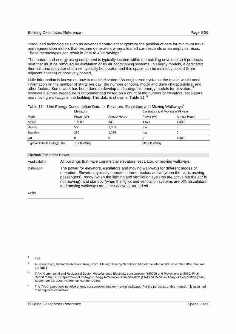
Building Descriptors Reference - Page 5-39
Building Descriptors Reference Space Uses
introduced technologies such as advanced controls that optimize the position of cars for minimum traveland regeneration motors that become generators when a loaded car descends or an empty car rises.These technologies can result in 35% to 40% savings.
4
The motors and energy using equipment is typically located within the building envelope so it producesheat that must be removed by ventilation or by air conditioning systems. In energy models, a dedicatedthermal zone (elevator shaft) will typically be created and this space can be indirectly cooled (fromadjacent spaces) or positively cooled.
Little information is known on how to model elevators. As engineered systems, the model would needinformation on the number of starts per day, the number of floors, motor and drive characteristics, andother factors. Some work has been done to develop and categorize energy models for elevators;
5
however a simple procedure is recommended based on a count of the number of elevators, escalatorsand moving walkways in the building. This data is shown in Table 11.
6
Table 11 – Unit Energy Consumption Data for Elevators, Escalators and Moving Walkways7
Mode
Elevators Escalators and Moving Walkways
Power (W) Annual Hours Power (W) Annual Hours
Active 10,000 300 4,671 4,380
Ready 500 7,365 n.a. 0
Standby 250 1,095 n.a. 0
Off 0 0 0 4,380
Typical Annual Energy Use 7,000 kWh/y 20,500 kWh/y
Elevator/Escalator Power
All buildings that have commercial elevators, escalator, or moving walkways
The power for elevators, escalators and moving walkways for different modes ofoperation. Elevators typically operate in three modes: active (when the car is movingpassengers), ready (when the lighting and ventilation systems are active but the car isnot moving), and standby (when the lights and ventilation systems are off). Escalatorsand moving walkways are either active or turned off.
4 Ibid.
5Al-Sharif, Lutfi, Richard Peters and Rory Smith, Elevator Energy Simulation Model, Elevator World, November 2005, VolumeLII, No11
6 TIAX, Commercial and Residential Sector Miscellaneous Electricity consumption: Y20005 and Projections to 2030, FinalReport to the U.S. Department of Energy's Energy Information Administration (EIA) and Decision Analysis Corporation (DAC),September 22, 2006, Reference Number D0366.
7 The TIAX report does not give energy consumption data for moving walkways. For the purposes of this manual, it is assumedto be equal to escalators.
Applicability
Definition
Units

Building Descriptors Reference - Page 5-40
Building Descriptors Reference Space Uses
W/unit
The power values from Table 11 for different modes of operation are prescribed for theproposed design.
Same as the proposed design
Not applicable
Elevator/Escalator Schedule
All buildings that have commercial elevators, escalator, or moving walkways
The schedule of operation for elevators, escalators, and moving walkways. This isused to convert elevator/escalator power to energy use.
Data structure: schedule, state
The operating schedule is prescribed for California Compliance and Reach. ForCalifornia Compliance, an appropriate schedule from Appendix 5.4B shall be used. Ifvalues other than those shown in Appendix 5.4B are used, this will be reported as acondition requiring an Exceptional Condition Review by a third party reviewer
Same as the proposed design
Not applicable
5.4.8 Process, Gas
Commercial gas equipment includes the following:
Ovens
Fryers
Grills
Other equipment
The majority of gas equipment is located in the space and may contribute both sensible and latent heat.Gas equipment is typically modeled by specifying the rate of peak gas consumption and modifying thiswith a fractional schedule. Energy consumption data for gas equipment is only beginning to emerge.
Because of these limits, the procedure for commercial gas is limited. The procedure consists ofprescribed power and energy values for use with both the proposed design and the baseline building. Nocredit for commercial gas energy efficiency features is offered.
The prescribed values are provided in Appendix 5.4A. Schedules are defaulted to be continuousoperation.
Gas Equipment Power
All buildings that have commercial gas equipment
Commercial gas power is the average power for all commercial gas equipment,assuming constant year-round operation.
Input Restrictions
Standard Design
Standard Design,Existing Buildings
Applicability
Definition
Units
Input RestrictionsStandard Design
Standard Design
Standard Design,Existing Buildings
Applicability
Definition

Building Descriptors Reference - Page 5-41
Building Descriptors Reference Space Uses
Btu/h-ft²
The values in Appendix 5.4A are prescribed.
Same as the proposed design
Not applicable
Gas Equipment Schedule
All buildings that have commercial gas equipment
The schedule of operation for commercial gas equipment. This is used to convert gaspower to energy use.
Data structure: schedule, fractional
Continuous operation is prescribed.
Same as the proposed design
Not applicable
Gas Equipment Location
All buildings that have commercial gas equipment
The assumed location of the gas equipment for modeling purposes. Choices are in thespace or external.
List (see above)
As designed.
Same as the proposed design
Not applicable
Radiation Factor
Gas appliances located in the space
The fraction of heat gain to appliance energy use
Fraction
Default value is 0.15. Other values can be used when a detailed inventory ofequipment is known. The override value shall be based on data in Table 5C, Chapter18, ASHRAE HOF, 2009, or similar tested information from the manufacturer.
Same as the proposed design
Not applicable
Usage Factor
Gas appliances located in the space
A duty cycle or usage factor to appliance energy use
Units
Input Restrictions
Standard Design
Standard Design,Existing Buildings
Applicability
Definition
Units
Input Restrictions
Standard Design
Standard Design,Existing Buildings
Applicability
Definition
Units
Input Restrictions
Standard Design
Standard Design,Existing Buildings
Applicability
Definition
Units
Input Restrictions
Standard Design
Standard Design,Existing Buildings
Applicability
Definition

Building Descriptors Reference - Page 5-42
Building Descriptors Reference Space Uses
The radiation factor and usage factor are used together to determine the sensible heatgain to the space:
Qsens = Qinput x FU x FR
Where Qinput is the heat input of the equipment in Btu/h or Btu/h-ft2,
FU is the usage factor and
FR is the radiation factor
Fraction
Default value is 0.70. Other values can be used when a detailed inventory ofequipment is known. The override value shall be based on data in Table 5C, Chapter18, ASHRAE HOF, 2009, or similar tested information from the manufacturer.
Same as the proposed design
Not applicable
Process Loads
Spaces with process loads
Process load is the internal energy of a building resulting from an activity or treatmentnot related to the space conditioning, lighting, service water heating, or ventilating of abuilding as it relates to human occupancy. Process load may include sensible and/orlatent components
Data centers loads including transformers, UPS, PDU, server fans and power suppliesare considered receptacle loads, not process loads, and the equipment schedules aregiven in Appendix 5.4B.
Compliance software shall model and simulate process loads only if the amount of theprocess energy and the location and type of process equipment are specified in theconstruction documents. This information shall correspond to specific specialequipment shown on the building plans and detailed in the specifications. Thecompliance software Compliance Documentation shall inform the user that thecompliance software will output process loads including the types of processequipment and locations on the compliance forms.
Data structure: sensible (Btu/h), latent (Btu/h)
Compliance software shall receive input for Sensible and/or Latent Process Load foreach zone in the proposed design. The process load input shall include the amount ofthe process load (Btu/h-ft2) and the HVAC zone where the process equipment islocated. The modeled information shall be consistent with the plans and specificationsof the building.
The standard design shall use the same process loads for each zone as the proposeddesign.
Same as for new construction
Process Load Schedule
All buildings that have commercial gas equipment
The schedule of operation process load. This is used to convert gas power to energy
Units
Input Restrictions
Standard Design
Standard Design,Existing Buildings
Applicability
Definition
Units
Input Restrictions
Standard Design
Standard Design,Existing Buildings
Applicability
Definition

Building Descriptors Reference - Page 5-43
Building Descriptors Reference Building Envelope Data
use.
Data structure: schedule, fractional
As designed.
Same as the proposed design
Not applicable
Process Load Location
All buildings that have commercial gas equipment
The assumed location of process load for modeling purposes. Choices are in thespace or external.
List (see above)
As designed.
Same as the proposed design
Not applicable
5.5 Building Envelope Data
5.5.1 Materials
Energy simulation programs commonly define construction assemblies by listing a sequence of materiallayers that make up the construction assembly. Typical construction assemblies and their respectivematerial layers are defined in Reference Appendix JA4. Additionally, the properties of the each materiallayer can be found in ACM Appendix 5.5A.
Material Name
When construction assemblies reference materials that are not standard
The name of a construction material used in the exterior envelope of the building
Text: unique
Material name is a required input for materials not available from the standard list inACM Appendix 5.5A. The user may not modify entries for predefined materials.
Not applicable
Density
All non-standard materials
The density (or mass per unit of volume) of the construction material as documented inan ASHRAE handbook, a comparably reliable reference, or manufacturers’ literature.
lb/ft3
Units
Input Restrictions
Standard Design
Standard Design,Existing Buildings
Applicability
Definition
Units
Input Restrictions
Standard Design
Standard Design,Existing Buildings
Applicability
Definition
Units
Input Restrictions
Standard Design
Applicability
Definition
Units
Input Restrictions

Building Descriptors Reference - Page 5-44
Building Descriptors Reference Building Envelope Data
Density is a required input when non-standard materials are specified.
Not applicable
Specific Heat
All non-standard materials
The specific heat capacity of a material is numerically equal to the quantity of heat thatmust be supplied to a unit mass of the material to increase its temperature by 1 °F
Btu/lb·°F
Specific heat is a required input when non-standard materials are specified. Thespecific heat capacity of the construction material as documented in an ASHRAEhandbook, a comparably reliable reference, or manufacturers’ literature.
Not applicable
Thermal Conductivity
All non-standard materials
The thermal conductivity of a material of unit thickness is numerically equal to thequantity of heat that will flow through a unit area of the material when the temperaturedifference through the material is 1 °F.
Btu/h·ft·°F
Thermal conductivity is a required input for non-standard materials.
Not applicable
Thickness
All non-standard materials
The thickness of a material
ft or in.
Thickness is a required input for non-standard materials. The user shall document thedata source for thermal conductivity used for additional materials under the materialname descriptor.
Not applicable
Reflectance
All opaque exterior surfaces exposed to ambient conditions; this is fixed for exteriorwalls at 0.3 and is the as-designed value entered for roofs, with some restrictions.
The solar reflectance of a material. For roofing materials, the 3-year aged reflectancevalue from CRRC testing should be used if available.
Unitless fraction between 0 and 1
For new construction, if asphalt shingles or composition shingles are not rated by theCool Roof Rating Council (CRRC), the default aged solar reflectance and emittancemust be equal to or more efficient than the mandatory requirements in Section 110.8
Standard Design
Applicability
Definition
Units
Input Restrictions
Standard Design
Applicability
Definition
Units
Input Restrictions
Standard Design
Applicability
Definition
Units
Input Restrictions
Standard Design
Applicability
Definition
Units
Input Restrictions

Building Descriptors Reference - Page 5-45
Building Descriptors Reference Building Envelope Data
of the Standards. The default value may be overridden when roof materials are usedthat have been tested by the (CRRC) and are called for in the constructiondocuments. In cases where the default value is overridden, the user is required tosubmit documentation identifying the test procedure that was used to establish thenon-default values. If the aged reflectance is not known, the aged reflectance may becalculated from the initial reflectance by the following equation:
ƿaged = 0.2 + β · (ƿinit – 0.2)
Where,
ƿaged = the calculated aged reflectance
β = 0.65 for field-applied coatings, 0.7 for all other roof surfaces
ƿnit = the initial reflectance
For new construction, the standard design reflectance shall meet the requirementsstated in Section 140.3 of the Standards. Thermal emittance shall be 0.85.
For alterations to more than 50% of the roof area or roof areas above 2,000 ft2
thestandard design shall be modeled as the more efficient of either the existing conditionsor the values required for cool roofs under Section 141.0 of the Standards. Theroughness shall be set to the same value as the proposed design.
SPECIAL NOTE: A SIMPLIFIED VERSION OF THE COMPLIANCE SOFTWARE WILL BE
DEVELOPED TO BE USED FOR ENVELOPE TRADEOFFS, AND FOR ROOF ALTERATIONS IN
PARTICULAR. THIS OPTION WILL CONSTRAIN ALMOST ALL INPUTS NOT RELATED TO ROOF
PERFORMANCE AND WILL PROVIDE A WAY TO DETERMINE INSULATION TRADEOFFS
ALLOWED WITH ROOF REFLECTANCE.
5.5.2 Construction Assemblies
For California Compliance and Reach, construction assemblies for the proposed design shall be createdby selecting from a library of building construction layers in ACM Appendix 5.5A. Choices from ReferenceAppendix JA4 are specified for the standard design building in ACM Appendix 5.5C. When a choice ismade, all properties of the proposed design construction assembly are set, except as specified in thismanual. The materials and layers that make up the construction assemblies are documented in the notessection of each table in Reference Appendix JA4. The choice from Reference Appendix JA4 alsodetermines the construction of the standard design, according to the mappings shown in ACM Appendix5.5C.
Geometry
The geometry of roofs, walls, floors, doors and fenestration should match the construction documents oras-built drawings as accurately as possible. Unusual curved surfaces such as a dome or semi ciricularwall may be approximated by a series of constructions.
Mass Walls
For mass walls, the user first chooses the mass layer from either Tables 4.3.5 or 4.3.6 of ReferenceAppendix JA4. After that, the user may select an insulating layer from Table 4.3.7 for outside and/orinside the mass wall. Up to three choices may be selected from Reference Appendix JA4.
Standard Design

Building Descriptors Reference - Page 5-46
Building Descriptors Reference Building Envelope Data
Ballasted Roofs, Vegetated Roofs, Concrete Pavers, and Other Mass Roofs
An additional layer may be added to the construction assembly specified in Reference Appendix JA4when thermal mass is used above the roof membrane. This exception is intended to allow ballasted roofs,concrete pavers and other massive elements to be explicitly modeled. To qualify, the weight of the stoneballast, the concrete pavers or other elements must exceed 15 lb/ft². The thickness, heat capacity,conductance and density of the additional mass layer shall be based on the measured physical propertiesof the material. If the surface properties of the additional mass material have been verified through theCool Roof Rating Council (CRRC), the CRRC reported properties may be used for the proposed design;otherwise, the mass layer shall be modeled with an aged reflectance of 0.10 and an emittance of 0.85.
Assembly Name
All projects
The name of a construction assembly that describes a roof, wall, or floor assembly.The name generally needs to be unique so it can be referenced precisely by surfaces.
Text: unique
Construction name is a required input. The name should reference the table number,row and column in Reference Appendix JA4.
Not applicable
Specification Method
All projects
The method of describing a construction assembly. The more simple method is todescribe the U-factor of the construction assembly which can account for thermalbridging and other factors. However with this method, the time delay of heat transferthrough the construction assembly is not accounted for. Generally, with the U-factormethod, heat transfer is assumed to occur instantly. The more complex method is todescribe the construction assembly as a series of layers, each layer representing amaterial. With this method, heat transfer is delayed in accord with the thermal massand other properties of the assembly.
List: layers
The layers method shall be used for all constructions except for metal building orsimilar constructions with negligible thermal mass.
For each construction, the proposed design specification method shall be used.
Layers
All construction assemblies that use the layers method of specification
A structured list of material names that describe a construction assembly, beginningwith the exterior finish and progressing through the assembly to the interior finish.Material names must be from ACM Appendix 5.5A.
List: layers of construction assembly
The user is required to describe all layers in the actual assembly and model theproposed design based the layer descriptions.
See building descriptors for Roofs, Exterior Walls, Exterior Floors, Doors, Fenestrationand Below Grade Walls.
Applicability
Definition
Units
Input Restrictions
Standard Design
Applicability
Definition
Units
Input Restrictions
Standard Design
Applicability
Definition
Units
Input Restrictions
Standard Design

Building Descriptors Reference - Page 5-47
Building Descriptors Reference Building Envelope Data
5.5.3 Roofs
Roof Name
All roof surfaces
A unique name or code that identifies the roof and ties it to the construction documentssubmitted for energy code review. It is not mandatory to name roofs.
Text: unique
None
None
Roof Type
All roof surfaces
A roof classification defined in the Standards. The prescriptive U-factor requirementsfor roofs depend on the roof type and the climate. For California, the roof classificationis determined from the proposed design construction choice from Reference AppendixJA4.
This descriptor can be derived from other building descriptors and it may not benecessary for the software user to specify it directly.
List: metal building, wood framed or other
As designed
The roof classification shall be metal building.
Roof Geometry
All roofs, required input
Roof geometry defines the position, orientation, azimuth, tilt, and dimensions of theroof surface. The details of how the coordinate system is implemented may varybetween software programs. The data structure for surfaces is described in thereference section of this chapter.
Data structure: surface
There are no restrictions other than that the surfaces defined must agree with thebuilding being modeled, as represented on the construction drawings or as-builtdrawings.
Roof geometry will be identical in the proposed and standard design building designs.
For alterations, roof geometry will be fixed, based on one of the building prototypes(office, retail, etc.)
Roof Construction
All roofs, required input
A specification containing a series of layers that result in a construction assembly forthe proposed design. The first layer in the series represents the outside (or exterior)layer and the last layer represents the inside (or interior) layer. See the buildingdescriptors above for roof construction type.
List: layers
Applicability
Definition
Units
Input Restrictions
Standard Design
Applicability
Definition
Units
Input Restrictions
Standard Design
Applicability
Definition
Units
Input Restrictions
Standard Design
Applicability
Definition
Units

Building Descriptors Reference - Page 5-48
Building Descriptors Reference Building Envelope Data
The construction assembly, defined by a series of layers, must be equal to or moreefficient than the mandatory U-factor requirements of Section 120.7 of the Standardsfor new construction, and Section 141.0 of the Standards for alterations. Each layerspecified must be listed in the materials database in the ACM Appendix 5.5A.Appropriate R-values for insulation can be calculated using the formula below.
Rinsulation = (1/U-factor) – Rlayer(1) – Rlayer(2) – Rlayer(3) – Rlayer(n)
Rinsulation = Rins.continuous + Rins.framing
For new construction, the standard design roof type is metal framed. The U-factorrequired for roof construction is defined in Table 140.3-B, C or D of the Standards.Programs that model a U-factor shall use an outside air film resistance and an insideair film resistance of R-0.17 and R-0.62, respectively.
For metal building roofs, the standard design construction shall include the followinglayers:
Outside Air Film R - 0.17
Roof Gravel or Slag (1.0 in.) R - 0.10
Insulation Entirely Above Deck Rinsulation
Plywood (1/2 in.) R - 0.63
Metal Deck R - 0.00
Metal Framing R - 0.00
Air Layer (4 in. or more) R - 0.92
Acoustic Tile (3/4 in.) R - 1.89
Inside Air Film R - 0.62
The R-value of Insulation Entirely Above Deck shall be set to achieve the following U-factors:
Nonresidential Buildings
Climate Zones 2, 3, 4, 9-16: U=0.039
Climate Zones 1, 5: U=0.049
Climate Zones 7, 8: U=0.067
Climate Zones 6: U=0.075
High-Rise Residential Buildings and Hotel Guestrooms
Climate Zones 2,4,8-16: U=0.028
Climate Zone 1: U=0.034
Climate Zone 3, 5-7: U=0.039
For alterations, any approved roof type may be used. The U-factor in the standarddesign shall be modeled as the more efficient of either the existing conditions or thevalues stated in Section 141.0 of the Standards. Where applicable, selection shall bebased on building type, assembly, and climate zone. A construction of layers shall bedefined to yield an equivalent U-factor.
For roof construction, the alteration standard design assembly shall include theappropriate existing layers.
Input Restrictions
Standard Design

Building Descriptors Reference - Page 5-49
Building Descriptors Reference Building Envelope Data
5.5.4 Exterior Walls
Wall Name
All walls, optional input
A unique name or code that relates the exterior wall to the design documents. This isan optional input since there are other acceptable ways to key surfaces to theconstruction documents.
Text: unique
None
None
Wall Type
All wall surfaces, optional
One of four categories of above-grade wall assemblies used to determine minimuminsulation requirements for walls. The four wall type categories are as follows:
a) Mass walls,
b) Metal building walls,
c) Metal framing walls, and
c) Wood framing and other walls.
These wall types are defined in Reference Appendix JA4.
List: mass walls, metal building walls, metal framing walls, and wood framing and otherwalls
This input is optional for the purposes covered by this manual. This input can often bederived from other inputs and may not need to be explicitly specified.
All walls in the standard design building are modeled as “metal framed.”
Wall Geometry
All walls, required input
Wall geometry defines the position, orientation, azimuth, and tilt of the wall surface.The details of how the coordinate system is implemented may vary between simulationengines. The data structure for surfaces is described in the reference section of thischapter.
Data structure: surface
As designed
Wall geometry in the standard design building is identical to the proposed design.
Wall Construction
All walls that use the Layers method
A specification containing a series of layers that result in a construction assembly forthe proposed design. The first layer in the series represents the outside (or exterior)
Applicability
Definition
Units
Input Restrictions
Standard Design
Applicability
Definition
Units
Input Restrictions
Standard Design
Applicability
Definition
Units
Input Restrictions
Standard Design
Applicability
Definition
Building Descriptors Reference - Page 5-50
Building Descriptors Reference Building Envelope Data
layer and the last layer represents the inside (or interior) layer. See the buildingdescriptors above for wall construction type.
List: Layers
The construction assembly, defined by a series of layers, must be equal to or moreefficient than the mandatory U-factor requirements of Section 120.7 of the Standardsfor new construction, and Section 141.0 of the Standards for alterations. Each layerspecified must be listed in the materials database in the ACM Appendix 5.5A.Appropriate R-values for insulation can be calculated using the formula below.
Rinsulation = (1/U-factor) – Rlayer(1) – Rlayer(2) – Rlayer(3) – Rlayer(n)
Rinsulation = Rins.continuous + Rins.framing
For new construction, the standard design wall type is metal-framed with continuousinsulation as described in Table 4.3.3 of Reference Appendix JA4. The U-factorrequired for wall construction of the standard design building is defined in Table 140.3-B, C or D of the Standards. Programs that model a U-factor shall use an outside airfilm resistance and an inside air film resistance of R-0.17 and R-0.62, respectively.
For metal framed walls, the standard design construction shall include the followinglayers:
Outside Air Film R - 0.17
Stucco, 7/8” R - 0.18
Building Paper R - 0.06
Insulation Continuous Rinsulation
Metal Framing, no Insulation R - 0.00
Air Layer (4 in. or more) R - 0.92
Gypsum board (5/8 in.) R - 0.56
Inside Air Film R - 0.62
For alterations, any approved wall type may be used. The U-factor in the standarddesign shall be modeled as the more efficient of either the existing conditions or thevalues stated in Section 141.0 of the Standards. Where applicable, selection shall bebased on building type, assembly, and climate zone. A construction of layers shall bedefined to yield an equivalent U-factor.
For wall construction, the alteration standard design assembly shall include theappropriate existing layers.
5.5.5 Exterior Floors
Floor Name
All floor surfaces
A unique name or code that relates the exposed floor to the design documents.Exposed floors include floors exposed to the outdoors and floors over unconditionedspaces, but do not include slab-on-grade floors, below grade floors, or interior floors.
Text: unique
None
Units
Input Restrictions
Standard Design
Applicability
Definition
Units
Input Restrictions
Building Descriptors Reference - Page 5-51
Building Descriptors Reference Building Envelope Data
None
Floor Type
All exterior floor surfaces, optional
One of three categories of exposed floor assemblies used to determine minimumprescriptive insulation requirements. The three floor type categories are:
a) Mass floor,
b) Steel framed floor, and
c) Wood framed and other floors.
Explanations of these three exterior floor types are contained in Reference AppendixJA4. This building descriptor is not used for the purposes of this manual, since thetype for the standard design building is fixed at “steel joist”. This building descriptorcan often be derived from other information in the model and may not be `required asan explicit input.
List: mass floor, metal joist floor, and wood and other floors
This building descriptor input is optional for the purposes of this manual.
The standard design building floors shall be of type “steel joist.”
Floor Geometry
All exterior floors, required input
Floor geometry defines the position, orientation, azimuth, and tilt of the floor surface.The details of how the coordinate system is implemented may vary between softwareprograms. The data structure for surfaces is described in the reference section of thischapter.
Data structure: surface
As designed
Standard design building floor geometry is identical to the proposed design.
Floor Construction
All floors, required input
A specification containing a series of layers that result in a construction assembly forthe proposed design. The first layer in the series represents the outside (or exterior)layer and the last layer represents the inside (or interior) layer. See the buildingdescriptors above for floor construction type.
List: Layers
The construction assembly, defined by a series of layers, must be equal to or moreefficient than the mandatory U-factor requirements of Section 120.7 of the Standardsfor new construction, and Section 141.0 of the Standards for alterations. Each layerspecified must be listed in the materials database in the ACM Appendix 5.5A.Appropriate R-values for insulation can be calculated using the formula below.
Rinsulation = (1/U-factor) – Rlayer(1) – Rlayer(2) – Rlayer(3) – Rlayer(n)
Rinsulation = Rins.continuous + Rins.framing
For new construction, the floor type for the standard design building is steel framed.
Standard Design
Applicability
Definition
Units
Input Restrictions
Standard Design
Applicability
Definition
Units
Input Restrictions
Standard Design
Applicability
Definition
Units
Input Restrictions
Standard Design

Building Descriptors Reference - Page 5-52
Building Descriptors Reference Building Envelope Data
The U-factor required for floor construction is defined in Table 140.3-B, C or D of theStandards. Programs that model a U-factor shall use an outside air film resistanceand an inside air film resistance of R-0.17 and R-0.62, respectively.
For steel framed floors, the standard design construction shall include the followinglayers:
Outside Air Film R - 0.17
Exterior Finish (metal or none) R - 0.00
Insulation / Continuous Rinsulation
Steel joists R – 0.00
Air Layer (4 in. or more) R - 0.92
Wood sheathing (5/8 in.) R - 0.78
Carpet with Fibrous Pad R - 2.08
Inside Air Film (down) R - 0.92
For alterations, any approved floor type may be used. The U-factor in the standarddesign shall be modeled as the more efficient of either the existing conditions or thevalues stated in Section 141.0 of the Standards. Where applicable, selection shall bebased on building type, assembly, and climate zone. A construction of layers shall bedefined to yield an equivalent U-factor.
For floor construction, the alteration standard design assembly shall include theappropriate existing layers.
5.5.6 Doors
Door Name
All exterior doors, optional input
A unique name or code that relates the door to the design documents submitted.Doors that are more than 50% glass are treated as windows and must be determinedand entered by using the Fenestration building descriptors.
Text: unique
None
None
Door Type
All exterior doors, required input
One of two door classifications of either: swinging or non-swinging. Non-swinging aregenerally roll-up doors. The prescriptive U-factor requirements depend on door typeand climate. This building descriptor may be derived from other building descriptors,in which case a specific input is not necessary.
List: swinging or non-swinging
The door type shall be consistent with the type of door represented on the construction
Applicability
Definition
Units
Input Restrictions
Standard Design
Applicability
Definition
Units
Input Restrictions
Building Descriptors Reference - Page 5-53
Building Descriptors Reference Building Envelope Data
documents or as-built drawings.
The standard design building door type shall be the same as the proposed design.
Door Geometry
All exterior doors
Door geometry defines the position and dimensions of the door surface relative to itsparent wall surface. The azimuth and tilt (if any) of the door is inherited from the parentsurface. The position of the door within the parent surface is specified through X,Ycoordinates. The size is specified as a height and width (all doors are generallyassumed to be rectangular in shape). The details of how the geometry of doors isspecified may vary for each energy simulation program.
Data structure: opening
As designed
Door geometry in the standard design building is identical to the proposed design.
Door Construction
All exterior doors
The thermal transmittance of the door, including the frame.
Btu/h·ft2·°F
The construction assembly must be equal to or more efficient than the mandatory U-factor requirements of Section 110.6 of the Standards for new construction. Foralterations there are no restrictions.
For new construction, the U-factor required for door construction is defined in Table140.3-B, C or D of the Standards.
For alterations, the U-factor in the standard design shall be modeled as the moreefficient of either the existing conditions or the values stated in Table 140.3-B, C or Dof the Standards. Where applicable, selection shall be based on building type,assembly, and climate zone.
5.5.7 Fenestration
Note that fenestration includes windows, doors that have more than 50% glazed area, and skylights. Askylight is fenestration that has a tilt of less than 60° from horizontal.
Fenestration Name
All fenestration, optional input
A unique name or code that relates the fenestration to the design documents and aparent surface.
Text: unique
No restrictions
Not applicable
Fenestration Type (Vertical Fenestration)
Standard Design
Applicability
Definition
Units
Input Restrictions
Standard Design
Applicability
Definition
Units
Input Restrictions
Standard Design
Applicability
Definition
Units
Input Restrictions
Standard Design
Applicability

Building Descriptors Reference - Page 5-54
Building Descriptors Reference Building Envelope Data
All vertical fenestration
This is a classification of vertical fenestration that determines the thermal performanceand solar performance requirement for vertical fenestration.
List: Fixed, Operable, Curtain Wall, or Glazed Doors
No restrictions, other than that the vertical fenestration type must agree with the typespecified on the construction documents or the as-built drawings.
Same as the proposed design
Fenestration Type (Skylights)
All skylights
This is a classification of skylights that determines the thermal performance and solarperformance requirement for vertical fenestration.
List: Glass, curb-mounted, Glass, deck-mounted, or Plastic
No restrictions, other than the skylight types specified must agree with the constructiondocuments or the as-built drawings.
Same as the proposed design
Default Fenestration Type
All fenestration that uses default thermal performance factors
This is a classification of fenestration that determines the thermal performance forfenestration using defaults from Standards Section 110.6
List: Fixed, Operable, Greenhouse/garden, doors, or Skylight
As designed
Not applicable
Default Glazing Type
All fenestration that uses default thermal performance factors
This is a classification of fenestration that determines the thermal performance forfenestration using defaults from Standards Section 110.6
List: Single Pane, Double Pane, Glass Block
As designed
Not applicable
Fenestration Geometry
All fenestration
Fenestration geometry defines the position and dimensions of the fenestration surfacewithin its parent surface and the identification of the parent surface. The orientationand tilt is inherited from the parent surface. The details of how the coordinate systemis implemented may vary between Compliance Software programs.
Display Perimeter. Display perimeter is the length of an exterior wall in a B-2occupancy that immediately abuts a public sidewalk, measured at the sidewalk levelfor each story that abuts a public sidewalk. The compliance software shall allow the
Definition
Units:
Input Restrictions
Standard Design
Applicability
Definition
Units:
Input Restrictions
Standard Design
Applicability
Definition
Units:
Input Restrictions
Standard Design
Applicability
Definition
Units:
Input Restrictions
Standard Design
Applicability
Definition

Building Descriptors Reference - Page 5-55
Building Descriptors Reference Building Envelope Data
user to specify a value for the length of display perimeter, in feet, for each floor or storyof the building. The user entry for Display Perimeter shall have a default value of zero.Note: Any non-zero input for Display Perimeter is an exceptional condition that shall bereported on the PERF-1 exceptional condition list and shall be reported on the ENVforms. The value for Display Perimeter is used as an alternate means of establishingMaximum Wall Fenestration Area in the standard design (§140.3 of the Standards).
Floor Number. The compliance software shall also allow the user to specify theDisplay Perimeter associated with each floor (story) of the building.
Data structure: opening
Geometry is defined relative to the parent surface and can include setbacks.
Inputs include:
Geometry of opening (window or skylight), parent surface, display perimeter (optional),percent of roof area exempt from skylight requirements §140.3 of the Standards.
As designed.
Specification of the fenestration position within its parent surface is required for thefollowing conditions:
1) Exterior shading is modeled from buildings, vegetation, other objects; or
2) If daylighting is modeled within the adjacent space.
The standard design calculates the window wall ratio (WWR) for each orientation andthe overall window wall ratio for the building. The window wall ratio is the totalfenestration area (including framing) divided by the gross exterior wall area.
The geometry of the fenestration in the standard design shall be identical to theproposed design with the following exceptions:
Exception 1. Either the whole building window wall ratio or west window wall ratioexceeds 40%.
Exception 2. If display perimeter is entered, the fenestration area exceeds six timesthe display perimeter.
Exception 1. The fenestration is adjusted based on the following conditions:
Case 1. WWRo > 0.40, WWRw <=0.40
In this case, the fenestration area of all windows is reduced by multiplying thefenestration area by the ratio 0.40/WWRo. The dimensions of each window is reducedby multiplying the proposed window dimension by (0.40/WWRo)1/2, so that the samewindow aspect ratio is maintained.
Case 2: WWRo < 0.40. WWRw > 0.40
In this case, the fenestration area of all windows on the west orientation isreduced by multiplying the fenestration area by the ratio 0.40/WWRo. The dimensionsof each window is reduced by multiplying the proposed window dimension by(0.40/WWRo)
1/2, so that the same window aspect ratio is maintained.
Case 3: WWRo > 0.40. WWRw > 0.40
If both the west window wall ratio and the overall window wall ratio exceed theprescriptive limit of 0.40, the fenestration areas must be reduced by:
1) Adjust the West window area multiplying the west window area by the ratio0.4/WWRw.
Units
Input Restrictions
Standard Design

Building Descriptors Reference - Page 5-56
Building Descriptors Reference Building Envelope Data
2) Calculate the WWR of the north, east and south facades:
WWRnes = Window Area nes / Gross Wall Area nes
3) Adjust the window area of the windows on the north, east and south facadesby the following ratio:
WindowAreaN,std = WindowAreaN,prop x 0.4 / WWRnes
WindowAreaE,std = WindowAreaE,prop x 0.4 / WWRnes
WindowAreaS,std = WindowAreaS,prop x 0.4 / WWRnes
4) Adjust each window geometry for the west façade by multiplying eachdimension by (0.4/WWRw)
1/2
5) Adjust each window geometry for the north, east and south façade bymultiplying each dimension by (0.4/WWRnes)
1/2
Exception 2. If the display perimeter is entered and the window area exceeds theprescriptive limit, the window area for the standard design is calculated by multiplyingthe proposed window area by the following ratio:
WindowAreastd = 6 x DisplayPerimeter
The geometry of each window is modified by the following:
WindowHeightstd = WindowHeightprop x (WindowAreastd/WindowAreaprop)1/2
WindowWidthstd = WindowWidthprop x (WindowAreastd/WindowAreaprop)1/2
The following rules apply for calculating geometry of skylights:
The ratio of the total skylight area of the building to the total roof area, also called the Skylight toRoof ratio (SRR) ≤ 0.05, except for Atrium spaces with a ceiling height over 55 feet where SRR ≤ 0.10.
Depending on the following condition, adjustments to the SRR as described below shall be made.
i. For spaces other than auditoriums, churches, movie theaters, museums andrefrigerated warehouses- Builiding Floor area x 0.75 = Total primary daylit area+Total skylit daylit area. See 5.4.4 for detail description on Primary Daylit area andSkylit Daylit area.
ii. If the above condition is met and SRR ≤ 0.05, no adjustments are needed.
iii. If the condition is met and SRR > 0.05, skylight dimensions = Existing Dimensionx [1- √ (0.05/SRR of Proposed Building)]
iv. If the condition is not met triggering the need for additional skylights, the baselinecase shall be modeled with new skylights irrespective of the skylight location ofthe proposed case. The new skylights shall be distributed uniformly such thatthere is no overlapping of primary daylit areas from skylights or sidelights. Thedimension of the new skylights shall be the same as the proposed design ifcalculated new SRR ≤ 0.05. If SRR > 0.05, skylight dimensions = Existing Dimension x [1- √ (0.05/SRR of Proposed Building)].
Note that the adjustments to SRR is done after adjustments to WWR, if any is completed.
Skylight Requirement Exception Fraction
All buildings with interior ceiling heights greater than 15 feet
This is the fraction of floor area that is exempt from the minimum skylight area
Applicability
Definition

Building Descriptors Reference - Page 5-57
Building Descriptors Reference Building Envelope Data
requirement for spaces with high ceilings.
Identifying areas subject to §140.3 of the Standards
When a proposed space has ceiling heights greater than 15 feet, with exterior surfaceshaving a tilt angle less than 60 degrees (roofs) and no more than 3 stories abovegrade, the user shall enter the fraction of the modeled space that is exempt fromrequirements of §140.3 of the Standards. If the proposed design has skylights, theuser shall also indicate the area of the proposed design daylight area under skylightsin this space. When the user enters a value greater than 0 %for the fraction of thespace area exempt to §140.3 of the Standards, the compliance software shall requirethat the user indicate at least one of the following exceptions:
1. Designed general lighting is less than 0.5 W/ft2
2. Existing walls on plans result in enclosed spaces less than 5,000 ft2
3. Future walls or ceilings on plans result in enclosed spaces less than 5,000 ft2
orceiling heights less than 15 feet.
4. Plans or documents show that space is an auditorium, religious building ofworship, movie theater, museum, or refrigerated warehouses.
Data Structure:
(a) Unitless fraction between 0 and 1
List: Four exceptions listed above (specified if fraction > 0)
No restrictions, other than that the vertical fenestration type must agree with the typespecified on the construction documents or the as-built drawings.
Same as the proposed design
Fenestration Construction
All fenestration
A collection of values that together describe the performance of a fenestration system.The values that are used to specify the criteria are U-factor, SHGC and VT. U-factorand SHGC inputs are whole-window values.
Data structure: shall include at a minimum the following properties as specified byNFRC ratings:
U-factor: whole window U-factor
SHGC: whole window solar heat gain coefficient
VT: visible transmittance
For new construction, performance information for fenestration shall be developedfrom NFRC test procedures or shall be equal to or more efficient than therequirements of Section110.6 of the Standards, and the default values in Tables110.6-A and B of the Standards. Center-of-glass performance values for windowscomplying with the exception (maximum of 1,000 ft2) Values entered shall beconsistent with the specifications and the construction documents.
For buildings with fenestration area that meets requirements for use of center-of-glassU-factor and SHGC, the window overall U-factor, SHGC and VT shall be determinedby the following equations from the Reference Appendix NA6:
Units:
Input Restrictions
Standard Design
Applicability
Definition
Units
Input Restrictions
Building Descriptors Reference - Page 5-58
Building Descriptors Reference Building Envelope Data
UT = C1 + (C2 · Uc)
SHGCT = 0.08 + (0.86 · SHGCc)
VTT = VTF · VTC
Where,
UT = U-factor Is the Total Performance of the fenestration including glass and frame
C1 = Coefficient selected from Table NA6-5 in Reference Appendix NA6
C2 = Coefficient selected from Table NA6-5 in Reference Appendix NA6
UC = Center of glass U-factor calculated in accordance with NFRC 100 Section 4.5.3.1
SHGCT = SHGC Is
SHGCC = Center of glass SHGC calculated in accordance with NFRC 200 Section4.5.1.1
VTT = Is the Total Performance of the fenestration including glass and frame
VTF = 0.53 for projecting windows, such as casement and awning windows
VTF = 0.67 for operable or sliding windows
VTF = 0.77 for fixed or non-operable windows
VTF = 0.88 for curtain wall/storefront, Site-built and manufactured non-curb mountedskylights
VTF = 1.0 for Curb Mounted manufactured Skylights
VTC = Center of glass VT is calculated in accordance with NFRC 200 Section 4.5.1.1or NFRC 202 for Translucent Products or NFRC 203 for Tubular Daylighting Devicesand Hybrid Tubular Daylighting Devices or ASTM E972
For skylights, the default values shall be the alternate default U-factor and SHGCusing default calculations specified above and in Reference Appendix NA6 or the U-factor and SHGC listed in Table 110.6-A and Table 110.6-B in the Standards.
For alterations, the U-factor, SHGC and VT must be equal to or more efficient than themandatory requirements of Section 141.0 of the Standards.
For new construction, the requirements for vertical fenestration U factor, Solar HeatGain Coefficient, and Visible light transmission by window type and framing type arespecified in Table 140.3-B, C or D of the Standards.
For alterations, the U-factor, SHGC and VT in the standard design shall be modeledas the more efficient of either the existing conditions, or the values stated in Table141.0-A of the Standards when the existing window area is unchanged, or Table140.3-B, C or D of the Standards for all other cases.
External Shading Devices
All fenestration
Devices or building features that are documented in the construction documents andshade the glazing, such as overhangs, fins, shading screens, and setbacks ofwindows from the exterior face of the wall. Objects that shade the building but are not
Standard Design
Applicability
Definition
Building Descriptors Reference - Page 5-59
Building Descriptors Reference Building Envelope Data
part of the building and parts of the building that cause the building to shade itself arealso modeled, but are not a part of this building descriptor. See Shading of the BuildingSite. The Title 24 compliance software shall be capable of modeling vertical fins andoverhangs. Recessed windows may also be modeled with side fins and overhangs.
Data structure: opening shade
No restrictions other than that the inputs must match the construction documents
The standard design building is modeled without external shading devices.
Internal Shading Devices
All fenestration
Curtains, blinds, louvers, or other devices that are applied on the room side of theglazing material. Glazing systems that use blinds between the glazing layers are alsoconsidered internal shading devices. Glass coatings, components or treatments of theglazing materials are addressed through the Fenestration Construction buildingdescriptor.
Data structure: Indicates the type of control, or blind schedule if applicable
Interior shades shall only be modeled when automatic controls are present.
The standard design building shall be modeled with the same internal shadingdevices and shading schedule as the proposed design.
SHGC Dim Fraction
Fenestration with switchable glazing
For switchable glazing, this is the fraction of the solar heat gain coefficient whendarkened to the solar heat gain coefficient during normal operation. This can beapplied when the solar heat gain exceeds a specified threshold, or controlled by anelectrical signal.
Unitless
Between 0 and 1
Not applicable
VT Dim Fraction
Fenestration with switchable glazing
For switchable glazing, this is the fraction of the visible transmittance when darkenedto the visible transmittance during normal operation. This can be applied when thesolar heat gain exceeds a specified threshold, or controlled by an electrical signal.
Unitless
Between 0 and 1
Not applicable
Switchable Solar Heat Gain Threshold
Fenestration with automatically controlled switchable glazing.
Units
Input Restrictions
Standard Design
Applicability
Definition
Units
Input Restrictions
Standard Design
Applicability
Definition
Units
Input Restrictions
Standard Design
Applicability
Definition
Units
Input Restrictions
Standard Design
Applicability

Building Descriptors Reference - Page 5-60
Building Descriptors Reference Building Envelope Data
For switchable glazing, this is the solar heat gain threshold above which the dynamicglazing is active (darkened). When the solar heat gain drops below this threshold, theglazing is switched back to being inactive (clearest setting). Indoor and outdoor airtemperatures are the setpoints required for controlling the Switchable Solar Heat GainThreshold. A flag may be used to indicate that this control is not used.
Incident solar threshold (Btu/h-ft2)
As designed.
Not applicable
Switchable Space Temperature Threshold
Fenestration with automatically controlled switchable glazing.
For switchable glazing, this is the space temperature above which the dynamic glazingis active (darkened). When the solar heat gain drops below this threshold, the glazingis switched back to being inactive (clearest setting). Indoor and outdoor airtemperatures are the setpoints required for controlling the Switchable Solar Heat GainThreshold. This may be used in combination with the solar heat gain and illuminancethresholds for control. A flag may be used to indicate that this control is not used.
°F
The space heating and cooling setpoints are prescribed from Appendix 5.4B. A flagmay be used to indicate that this control is not used.
Not applicable
Switchable Illuminance Threshold
Fenestration with automatically controlled switchable glazing.
For switchable glazing, this is the illuminance threshold above which the dynamicglazing is regulated between active (darkened) and inactive (clearest setting). With asingle illuminance setpoint the switchable glazing will adjust between the clearest anddarkest setting to allow the desired illuminance level. A flag may be used to indicatethat this control is not used.
Lux
As designed
During occupied hours, the recommendation for the illuminance threshold setpoint is tomatch a point within the recommended illumination levels, based on space type, fromAppendix 5.4A. Values below this recommended range may require specialdocumentation.
During unoccupied hours, the recommendation is to have the Switchable Solar HeatGain Threshold descriptor in control of the switchable glass.
Not Applicable
Definition
Units
Input Restrictions
Standard Design
Applicability
Definition
Units
Input Restrictions
Standard Design
Applicability
Definition
Units
Input Restrictions
Standard Design

Building Descriptors Reference - Page 5-61
Building Descriptors Reference Building Envelope Data
Switchable Glazing Schedule
Fenestration with switchable glazing controlled by an electrical signal
For switchable glazing, this is an hourly schedule for the when the switchable glazingis darkened, when controlled by an electrical signal.
Boolean: 1 if switchable glazing is active (darkened); 0 if not active
0 or 1 for schedule values
Not applicable
5.5.8 Below Grade Walls
Below Grade Wall Name
All projects, optional input
A unique name that keys the below grade wall to the construction documents
Text: unique
None
Not applicable
Below Grade Wall Geometry
All projects
A geometric construct that describes the dimensions and placement of walls locatedbelow grade. Below grade walls have soil or crushed rock on one side and interiorspace on the other side. Some simulation models take the depth below grade intoaccount when estimating heat transfer, so the geometry may include height and width.
Data structure: below grade wall geometry
As designed
The geometry of below grade walls in the standard design building is identical to thebelow grade walls in the proposed design.
Below Grade Wall Construction
All projects, required input
A specification containing a series of layers that result in a construction assembly forthe proposed design. The first layer in the series represents the outside (or exterior)layer and the last layer represents the inside (or interior) layer. See the buildingdescriptors above for below grade wall construction type.
Data structure: construction assembly
The construction can be described as a C-factor which is similar to a U-factor, exceptthat the outside air film is excluded, or the construction can be represented as a seriesof layers, like exterior constructions.
For new construction, there are no restrictions other than that the inputs shall be inagreement with the construction documents. Values for the C-factor shall be takenfrom Table 4.3.5, 4.3.6 or 4.3.7 of Reference Appendix JA4.
Applicability
Definition
Units
Input Restrictions
Standard Design
Applicability
Definition
Units:
Input Restrictions
Standard Design
Applicability
Definition
Units
Input Restrictions
Standard Design
Applicability
Definition
Units
Input Restrictions
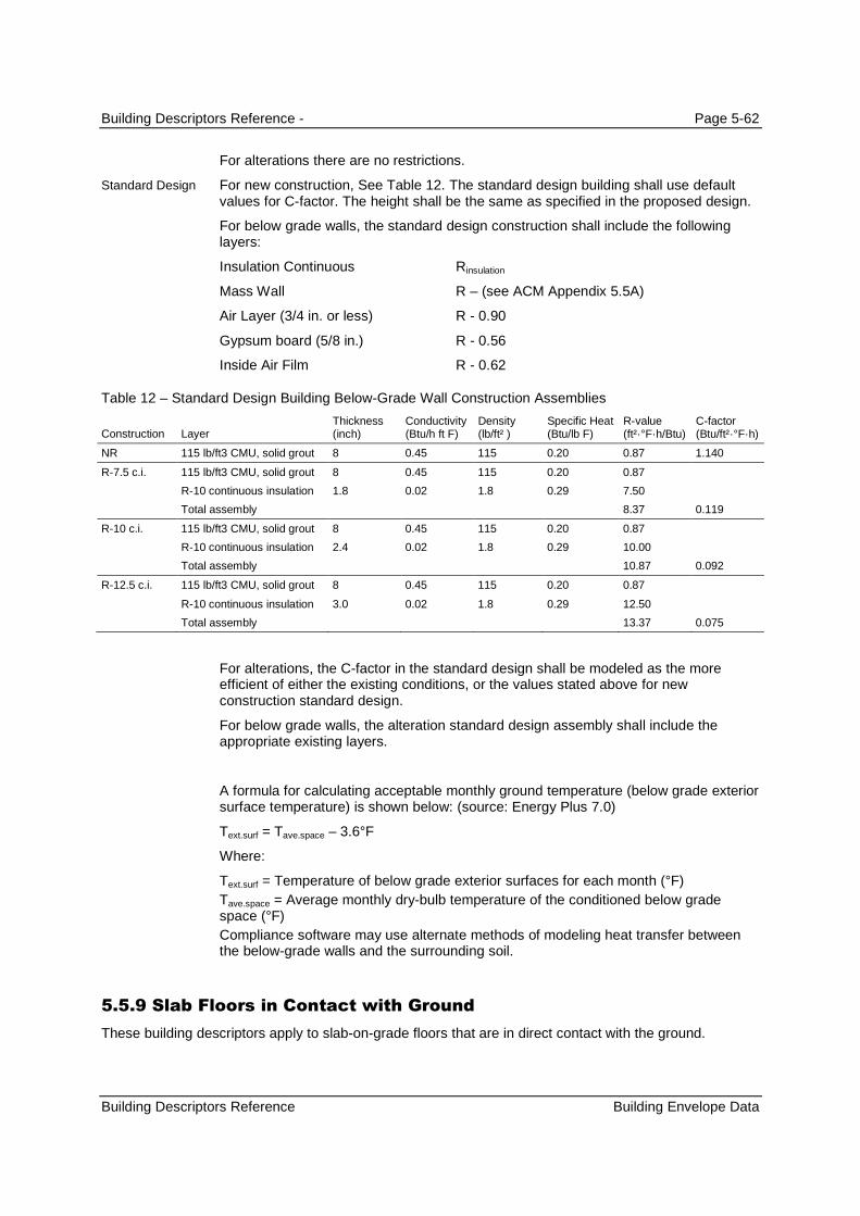
Building Descriptors Reference - Page 5-62
Building Descriptors Reference Building Envelope Data
For alterations there are no restrictions.
For new construction, See Table 12. The standard design building shall use defaultvalues for C-factor. The height shall be the same as specified in the proposed design.
For below grade walls, the standard design construction shall include the followinglayers:
Insulation Continuous Rinsulation
Mass Wall R – (see ACM Appendix 5.5A)
Air Layer (3/4 in. or less) R - 0.90
Gypsum board (5/8 in.) R - 0.56
Inside Air Film R - 0.62
Table 12 – Standard Design Building Below-Grade Wall Construction Assemblies
Construction LayerThickness(inch)
Conductivity(Btu/h ft F)
Density(lb/ft² )
Specific Heat(Btu/lb F)
R-value(ft²·°F·h/Btu)
C-factor(Btu/ft²·°F·h)
NR 115 lb/ft3 CMU, solid grout 8 0.45 115 0.20 0.87 1.140
R-7.5 c.i. 115 lb/ft3 CMU, solid grout 8 0.45 115 0.20 0.87
R-10 continuous insulation 1.8 0.02 1.8 0.29 7.50
Total assembly 8.37 0.119
R-10 c.i. 115 lb/ft3 CMU, solid grout 8 0.45 115 0.20 0.87
R-10 continuous insulation 2.4 0.02 1.8 0.29 10.00
Total assembly 10.87 0.092
R-12.5 c.i. 115 lb/ft3 CMU, solid grout 8 0.45 115 0.20 0.87
R-10 continuous insulation 3.0 0.02 1.8 0.29 12.50
Total assembly 13.37 0.075
For alterations, the C-factor in the standard design shall be modeled as the moreefficient of either the existing conditions, or the values stated above for newconstruction standard design.
For below grade walls, the alteration standard design assembly shall include theappropriate existing layers.
A formula for calculating acceptable monthly ground temperature (below grade exteriorsurface temperature) is shown below: (source: Energy Plus 7.0)
Text.surf = Tave.space – 3.6°F
Where:
Text.surf = Temperature of below grade exterior surfaces for each month (°F)
Tave.space = Average monthly dry-bulb temperature of the conditioned below gradespace (°F)
Compliance software may use alternate methods of modeling heat transfer betweenthe below-grade walls and the surrounding soil.
5.5.9 Slab Floors in Contact with Ground
These building descriptors apply to slab-on-grade floors that are in direct contact with the ground.
Standard Design
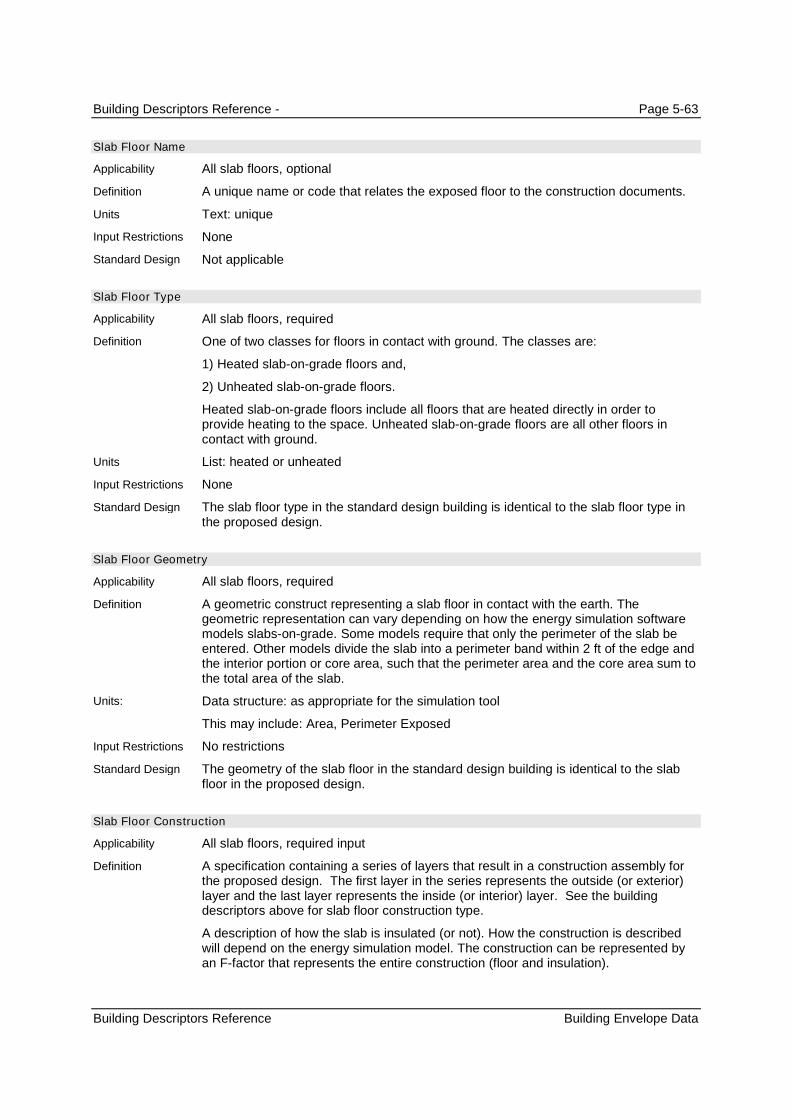
Building Descriptors Reference - Page 5-63
Building Descriptors Reference Building Envelope Data
Slab Floor Name
All slab floors, optional
A unique name or code that relates the exposed floor to the construction documents.
Text: unique
None
Not applicable
Slab Floor Type
All slab floors, required
One of two classes for floors in contact with ground. The classes are:
1) Heated slab-on-grade floors and,
2) Unheated slab-on-grade floors.
Heated slab-on-grade floors include all floors that are heated directly in order toprovide heating to the space. Unheated slab-on-grade floors are all other floors incontact with ground.
List: heated or unheated
None
The slab floor type in the standard design building is identical to the slab floor type inthe proposed design.
Slab Floor Geometry
All slab floors, required
A geometric construct representing a slab floor in contact with the earth. Thegeometric representation can vary depending on how the energy simulation softwaremodels slabs-on-grade. Some models require that only the perimeter of the slab beentered. Other models divide the slab into a perimeter band within 2 ft of the edge andthe interior portion or core area, such that the perimeter area and the core area sum tothe total area of the slab.
Data structure: as appropriate for the simulation tool
This may include: Area, Perimeter Exposed
No restrictions
The geometry of the slab floor in the standard design building is identical to the slabfloor in the proposed design.
Slab Floor Construction
All slab floors, required input
A specification containing a series of layers that result in a construction assembly forthe proposed design. The first layer in the series represents the outside (or exterior)layer and the last layer represents the inside (or interior) layer. See the buildingdescriptors above for slab floor construction type.
A description of how the slab is insulated (or not). How the construction is describedwill depend on the energy simulation model. The construction can be represented byan F-factor that represents the entire construction (floor and insulation).
Applicability
Definition
Units
Input Restrictions
Standard Design
Applicability
Definition
Units
Input Restrictions
Standard Design
Applicability
Definition
Units:
Input Restrictions
Standard Design
Applicability
Definition

Building Descriptors Reference - Page 5-64
Building Descriptors Reference Building Envelope Data
Simple models may include just an F-factor, representing an instantaneous heatloss/gain to outside air. The F-factor could be related to the configuration of insulationin the proposed design. Other slab loss models may require that the surface area ofthe slab floor be divided between the perimeter and the interior. The insulationconditions then define heat transfer between both outside air and ground temperature.
The insulation condition for slabs includes the R-value of the insulation and thedistance it extends into the earth at the slab edge and how far it extends underneaththe slab.
List
F-factor from Reference Appendix JA4; this is one selection from list 1 and oneselection from list 2. Note that some combinations from list 1 and list3 are not allowed– see Reference Appendix JA4 Table 4.4.8 and Table 4.4.7 for details.
List 1: None, 12 in horizontal, 24 in horizontal, 36 in horizontal, 48 in horizontal, 12 invertical, 24 in vertical, 36 in vertical, 48 in vertical, Fully insulated slab
List 2: R-0, R-5, R-7.5, R-10, R-15, R-20, R-25, R-30, R-35, R-40, R-45, R-50, R-55
For new construction, F-factors shall be taken from Table 4.4.8 of Reference AppendixJA4 for heated slab floors and Table 4.4.7 for unheated slab floors. For all methods,inputs shall be consistent with the construction documents. For heated slab floors, theF-factor shall be determined by the mandatory R-value and installation requirements inSection 110.8 of the Standards, and then that information is used in Table 4.4.8 ofReference Appendix JA4 to determine the required F-factor. For alterations the samerequirements apply.
Slab loss shall be modeled with the simple method (F-factor).
For new construction, the configuration of insulation and the F-factors for the standarddesign building heated slab floors are shown in Table 4.4.8 in Reference AppendixJA4. The F-factor for the standard design shall be the following:
Climate Zones 1-15: 48 in vertical, R-5 insulation
Climate Zone 16: 48 in vertical, R-10 insulation
For unheated slab floors the standard design Slab Floor Construction shall be None.
For alterations, the F-factor in the standard design shall be modeled as the moreefficient of either the existing conditions, or the values stated above for newconstruction standard design.
5.5.10 Heat Transfer between Thermal zones
Partition Name
All partitions, optional
A unique name or code that relates the partition to the construction documents.
Text: unique
The text should provide a key to the construction documents.
Not applicable
Partition Geometry
All partitions
Units
Input Restrictions
Standard Design
Applicability
Definition
Units
Input Restrictions
Standard Design
Applicability
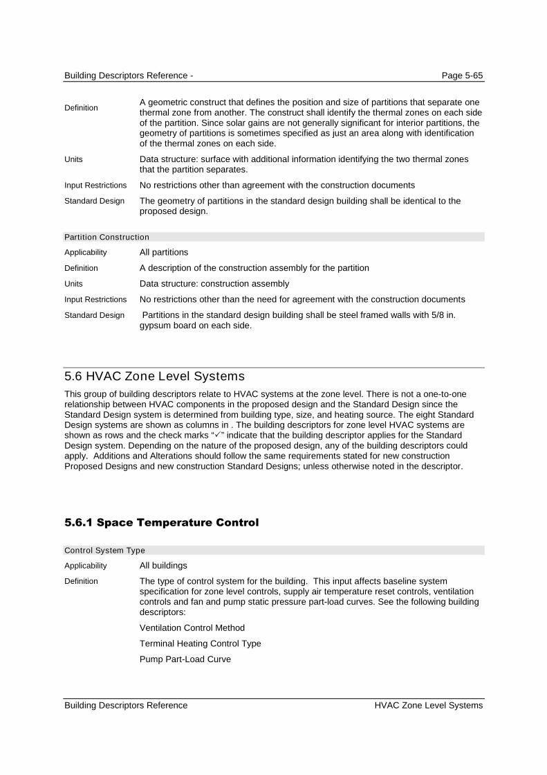
Building Descriptors Reference - Page 5-65
Building Descriptors Reference HVAC Zone Level Systems
A geometric construct that defines the position and size of partitions that separate onethermal zone from another. The construct shall identify the thermal zones on each sideof the partition. Since solar gains are not generally significant for interior partitions, thegeometry of partitions is sometimes specified as just an area along with identificationof the thermal zones on each side.
Data structure: surface with additional information identifying the two thermal zonesthat the partition separates.
No restrictions other than agreement with the construction documents
The geometry of partitions in the standard design building shall be identical to theproposed design.
Partition Construction
All partitions
A description of the construction assembly for the partition
Data structure: construction assembly
No restrictions other than the need for agreement with the construction documents
Partitions in the standard design building shall be steel framed walls with 5/8 in.gypsum board on each side.
5.6 HVAC Zone Level Systems
This group of building descriptors relate to HVAC systems at the zone level. There is not a one-to-onerelationship between HVAC components in the proposed design and the Standard Design since theStandard Design system is determined from building type, size, and heating source. The eight StandardDesign systems are shown as columns in . The building descriptors for zone level HVAC systems areshown as rows and the check marks “” indicate that the building descriptor applies for the StandardDesign system. Depending on the nature of the proposed design, any of the building descriptors couldapply. Additions and Alterations should follow the same requirements stated for new constructionProposed Designs and new construction Standard Designs; unless otherwise noted in the descriptor.
5.6.1 Space Temperature Control
Control System Type
All buildings
The type of control system for the building. This input affects baseline systemspecification for zone level controls, supply air temperature reset controls, ventilationcontrols and fan and pump static pressure part-load curves. See the following buildingdescriptors:
Ventilation Control Method
Terminal Heating Control Type
Pump Part-Load Curve
Definition
Units
Input Restrictions
Standard Design
Applicability
Definition
Units
Input Restrictions
Standard Design
Applicability
Definition

Building Descriptors Reference - Page 5-66
Building Descriptors Reference HVAC Zone Level Systems
Fan Part-load Curve
None
List: can be one of the following inputs
DDC Control to the Zone Level – direct digital control systems with control to the zonelevel
Other – other control systems, including pneumatic and DDC systems without controlto the zone level
DDC Control to the Zone Level
Space Thermostat Throttling Range
All HVAC zones
The number of degrees that the room temperature must change to cause the HVACsystem to go from no heating or cooling (i.e., space temperatures floating) to fullheating or cooling.
Degrees Fahrenheit (°F)
The prescribed value is 2°F. No input is needed and the prescribed value may not beoverridden.
Same as the proposed design
Space Temperature Schedule
All HVAC zones
An hourly space thermostat schedule
Data structure: temperature schedule
The schedules specified in Appendix 5.4A and detailed in Appendix 5.4B shall be usedas a default. When the default temperature schedule is overridden, the user mustprovide justification for use of nonstandard space temperature schedule assumptions.
Schedules in the Standard Design shall be identical to the proposed design.
5.6.2 Terminal Device Data
Terminal Type
All HVAC zones
A terminal unit includes any device serving a zone (or group of zones collected in athermal zone) that has the ability to reheat or recool in response to the zonethermostat. This includes:
None (the case for single zone units)
VAV box
Series Fan-Powered VAV box
Parallel Fan-Powered VAV box
Induction-type VAV box
Units
Input Restrictions
Standard Design
Applicability
Definition
Units
Input Restrictions
Standard Design
Applicability
Definition
Units
Input Restrictions
Standard Design
Applicability
Definition
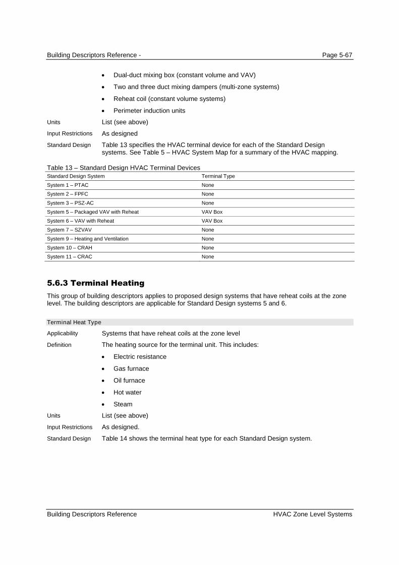
Building Descriptors Reference - Page 5-67
Building Descriptors Reference HVAC Zone Level Systems
Dual-duct mixing box (constant volume and VAV)
Two and three duct mixing dampers (multi-zone systems)
Reheat coil (constant volume systems)
Perimeter induction units
List (see above)
As designed
Table 13 specifies the HVAC terminal device for each of the Standard Designsystems. See Table 5 – HVAC System Map for a summary of the HVAC mapping.
Table 13 – Standard Design HVAC Terminal DevicesStandard Design System Terminal Type
System 1 – PTAC None
System 2 – FPFC None
System 3 – PSZ-AC None
System 5 – Packaged VAV with Reheat VAV Box
System 6 – VAV with Reheat VAV Box
System 7 – SZVAV None
System 9 – Heating and Ventilation None
System 10 – CRAH None
System 11 – CRAC None
5.6.3 Terminal Heating
This group of building descriptors applies to proposed design systems that have reheat coils at the zonelevel. The building descriptors are applicable for Standard Design systems 5 and 6.
Terminal Heat Type
Systems that have reheat coils at the zone level
The heating source for the terminal unit. This includes:
Electric resistance
Gas furnace
Oil furnace
Hot water
Steam
List (see above)
As designed.
Table 14 shows the terminal heat type for each Standard Design system.
Units
Input Restrictions
Standard Design
Applicability
Definition
Units
Input Restrictions
Standard Design

Building Descriptors Reference - Page 5-68
Building Descriptors Reference HVAC Zone Level Systems
Table 14 – Baseline Building Terminal Heat TypeBaseline building System Terminal Heat Type
System 1 – PTAC None
System 2 – PTHP None
System 3 – PSZ-AC None
System 4 – PSZ-HP None
System 5 – Packaged VAV with Reheat Hot Water
System 6– VAV with Reheat Hot Water
System 7 – SZVAV None
System 8 – SZVAV HP None
System 9 – Heating and Ventilation None
System 10 – CRAH Unit None
System 11 – CRAC Unit None
Terminal Heat Capacity
Systems that have reheat coils at the zone level
The heating capacity of the terminal heating source
Btu/h
As designed. However, if the unmet load hours exceed 300, the energy analyst anddesign team may have to increase the size of the equipment so that the unmet loadhours are less than 300. See Figure 7.
The software shall automatically size the terminal heating capacity to be 25% greaterthan the design loads. See Figure 7.
Reheat Delta T
Systems that have reheat coils at the zone level
This is an alternate method to enter the terminal heat capacity. It can be calculated asfollows:
(3)
Treheat = Treheat - Tcool_supply
Treheat = Qcoil / (1.1*CFM)
where
Treheat heat rise across the terminal unit heating coil (°F)
Treheat heating air temperature at design (°F)
Tcool_supply supply air temperature at the heating coil (°F)
Qcoil heating coil load (Btu/h)
CFM airflow (cfm)
Degrees Fahrenheit (°F)
As designed, but may need to be increased if unmet load hours are greater than 300.
Method not used for standard design. (The temperature difference shall be no more
Applicability
Definition
Units
Input Restrictions
Standard Design
Applicability
Definition
Units
Input Restrictions
Standard Design

Building Descriptors Reference - Page 5-69
Building Descriptors Reference HVAC Zone Level Systems
than 40F.) See Heat Capacity above.
5.6.4 Baseboard Heat
Baseboard Capacity
All HVAC zones
The total heating capacity of the baseboard unit(s)
Btu/h
As designed
Not applicable to the standard design
Baseboard Heat Control
All HVAC zones
Defines the control scheme of base board heating as either:
Controlled by a space thermostat
List (see above)
Controlled by space thermostat is the only type allowed if baseboard heating is used.
Not applicable for the standard design
5.6.5 Zone Level Air Flow
5.6.5.1 VAV Air Flow
This group of building descriptors applies to proposed design systems that vary the volume of air at thezone level. The building descriptors are applicable for standard design systems 5 and 6.
Design Airflow
Systems that vary the volume of air at the zone level
The air delivery rate at design conditions
cfm
As designed. If the unmet load hours in the proposed design are greater than 300, thebuilding descriptor may need to be modified to meet the criterion.
For systems 5 and 6, the software shall automatically size the system airflow to meetthe standard design loads based on a supply-air-to-room-air temperature difference of20°F, the required ventilation air from Table 120.1-A of the Standard, or makeup air;whichever is greater.
For kitchen MAU systems, the design airflow is the greater of the airflow required tomeet the design cooling loads and the total exhaust CFM.
Terminal Minimum Stop
Systems that vary the volume of air at the zone level
Applicability
Definition
Units
Input Restrictions
Standard Design
Applicability
Definition
Units
Input Restrictions
Standard Design
Applicability
Definition
Units
Input Restrictions
Standard Design
Applicability

Building Descriptors Reference - Page 5-70
Building Descriptors Reference HVAC Zone Level Systems
The minimum airflow that will be delivered by a terminal unit before reheating occurs
Unitless fraction of airflow (cfm) or specific airflow (cfm/ft²)
This input must be greater than or equal to the outside air ventilation rate.
For systems 5 and 6 set the minimum airflow to be the greater 20% of the peak supplyair volume to the zone or the outside air ventilation rate from Table 120.1-A, Section120.1(e) of the Standards.
For laboratories, the minimum airflow fraction shall be fixed at 1 (100% outside air).
Terminal Heating Control Type
VAV boxes with reheat
The control strategy for the heating mode.
Single Maximum
Dual Maximum: raises the SAT as the first stage of heating, and increases the airflowto the zone as the second stage of heating.
1. The first stage of heating consists of modulating the zone supply air temperaturesetpoint up to a maximum setpoint no larger than 95ºF while the airflow is maintainedat the dead band flow rate.
2. The second stage of heating consists of modulating the airflow rate from the deadband flow rate up to the heating maximum flow rate (50% of design flow rate).
Figure 6 – Dual Maximum Control Sequence
List:
Single Maximum
Dual Maximum
Fixed at Single Maximum if Control System Type is not DDC Control to the Zone Level
Dual Maximum
Definition
Units
Input Restrictions
Standard Design
Applicability
Definition
Units
Input Restrictions
Standard Design

Building Descriptors Reference - Page 5-71
Building Descriptors Reference HVAC Zone Level Systems
5.6.5.2 Fan Powered Boxes
Fan Powered Box Type
HVAC zones that have fan powered boxes
Defines the type of fan-powered induction box. This is either:
Series; or
Parallel
List (see above)
As designed
Not applicable
Fan Power
HVAC zones that have fan powered boxes
The rated power input of the fan in a fan-powered box.
W or W/cfm
As designed
Not applicable
Fan Powered Box Induced Air Zone
HVAC zones that have fan powered boxes
Zone from which a series or parallel fan-powered box draws its air
List (of zones)
As designed
Not applicable
Parallel PIU Induction Ratio
HVAC zones that have fan powered boxes
The ratio of induction-side airflow of a fan-powered box at design heating conditions tothe primary airflow
Ratio
As designed
Not applicable
Parallel Fan Box Thermostat Setpoint
HVAC zones that have parallel fan powered boxes
The temperature difference above the heating setpoint at which the parallel fan isturned on
Degrees Fahrenheit (°F)
Applicability
Definition
Units
Input Restrictions
Standard Design
Applicability
Definition
Units
Input Restrictions
Standard Design
Applicability
Definition
Units
Input Restrictions
Standard Design
Applicability
Definition
Units
Input Restrictions
Standard Design
Applicability
Definition
Units

Building Descriptors Reference - Page 5-72
Building Descriptors Reference HVAC Zone Level Systems
2°F above the heating setpoint schedule
Not applicable
5.6.5.3 Zone Exhaust
This group of building descriptors describes the rate of exhaust and the schedule or control for thisexhaust. An exhaust system can serve one thermal zone or multiple thermal zones. Energy is summedfor the exhaust system level, not the thermal zone level.
This section also contains unique inputs for kitchen exhaust systems that must meet requirements ofsection 140.9 of the Standards.
Kitchen Exhaust Hood Length
Exhaust fans in spaces of type Kitchen
The exhaust hood length
ft
As designed
Same as the proposed design
Kitchen Exhaust Hood Style
Exhaust fans in spaces of type Kitchen
The hood style as defined in Table 140.9-A of the Standards
List: Wall-mounted canopy, Single Island, Double Island, Eyebrow,Backshelf/Passover
As designed
Same as the proposed design
Kitchen Exhaust Hood Cooking Duty
Exhaust fans in spaces of type Kitchen
The hood cooking duty as defined in Table140.9-A of the Standards
List: Light Duty, Medium Duty, Heavy Duty, Extra Heavy Duty
As designed
Same as the proposed design
Exhaust Fan Name
All HVAC zones
A reference to an exhaust fan system that serves the thermal zone
Text or other unique reference to an exhaust fan system defined in the secondarysystems section.
As designed
Input Restrictions
Standard Design
Applicability
Definition
Units
Input Restrictions
Standard Design
Applicability
Definition
Units
Input Restrictions
Standard Design
Applicability
Definition
Units
Input Restrictions
Standard Design
Applicability
Definition
Units
Input Restrictions
Standard Design
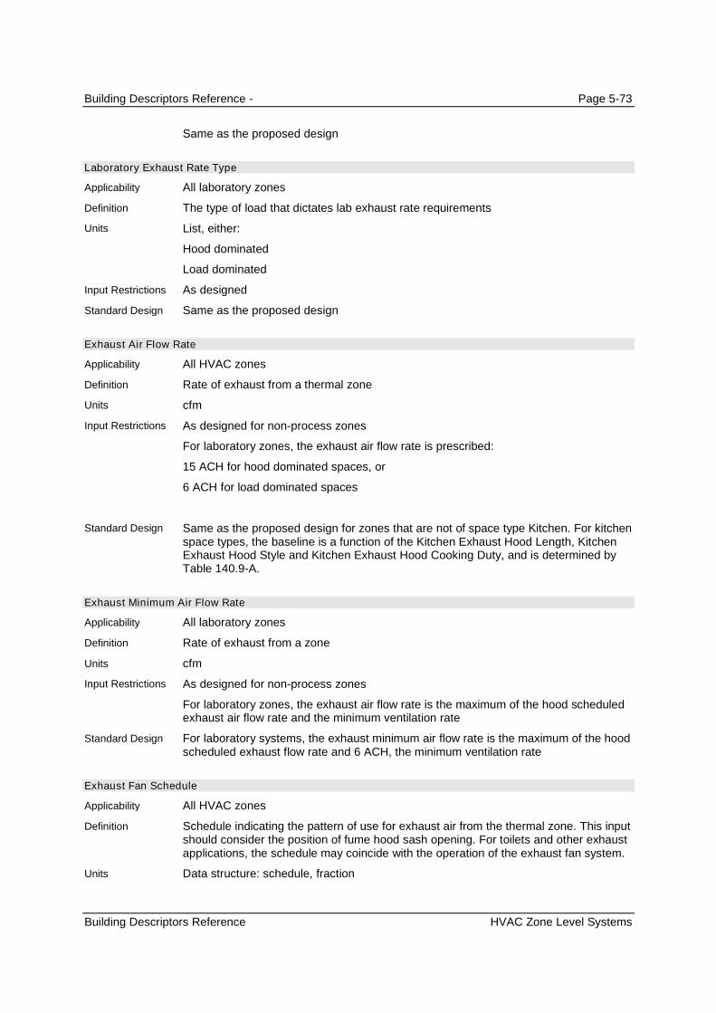
Building Descriptors Reference - Page 5-73
Building Descriptors Reference HVAC Zone Level Systems
Same as the proposed design
Laboratory Exhaust Rate Type
All laboratory zones
The type of load that dictates lab exhaust rate requirements
List, either:
Hood dominated
Load dominated
As designed
Same as the proposed design
Exhaust Air Flow Rate
All HVAC zones
Rate of exhaust from a thermal zone
cfm
As designed for non-process zones
For laboratory zones, the exhaust air flow rate is prescribed:
15 ACH for hood dominated spaces, or
6 ACH for load dominated spaces
Same as the proposed design for zones that are not of space type Kitchen. For kitchenspace types, the baseline is a function of the Kitchen Exhaust Hood Length, KitchenExhaust Hood Style and Kitchen Exhaust Hood Cooking Duty, and is determined byTable 140.9-A.
Exhaust Minimum Air Flow Rate
All laboratory zones
Rate of exhaust from a zone
cfm
As designed for non-process zones
For laboratory zones, the exhaust air flow rate is the maximum of the hood scheduledexhaust air flow rate and the minimum ventilation rate
For laboratory systems, the exhaust minimum air flow rate is the maximum of the hoodscheduled exhaust flow rate and 6 ACH, the minimum ventilation rate
Exhaust Fan Schedule
All HVAC zones
Schedule indicating the pattern of use for exhaust air from the thermal zone. This inputshould consider the position of fume hood sash opening. For toilets and other exhaustapplications, the schedule may coincide with the operation of the exhaust fan system.
Data structure: schedule, fraction
Applicability
Definition
Units
Input Restrictions
Standard Design
Applicability
Definition
Units
Input Restrictions
Standard Design
Applicability
Definition
Units
Input Restrictions
Standard Design
Applicability
Definition
Units
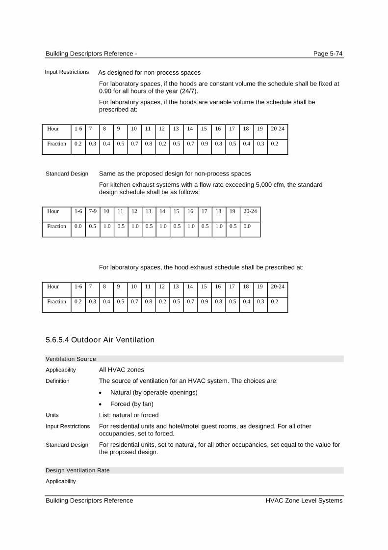
Building Descriptors Reference - Page 5-74
Building Descriptors Reference HVAC Zone Level Systems
As designed for non-process spaces
For laboratory spaces, if the hoods are constant volume the schedule shall be fixed at0.90 for all hours of the year (24/7).
For laboratory spaces, if the hoods are variable volume the schedule shall beprescribed at:
Hour 1-6 7 8 9 10 11 12 13 14 15 16 17 18 19 20-24
Fraction 0.2 0.3 0.4 0.5 0.7 0.8 0.2 0.5 0.7 0.9 0.8 0.5 0.4 0.3 0.2
Same as the proposed design for non-process spaces
For kitchen exhaust systems with a flow rate exceeding 5,000 cfm, the standarddesign schedule shall be as follows:
Hour 1-6 7-9 10 11 12 13 14 15 16 17 18 19 20-24
Fraction 0.0 0.5 1.0 0.5 1.0 0.5 1.0 0.5 1.0 0.5 1.0 0.5 0.0
For laboratory spaces, the hood exhaust schedule shall be prescribed at:
Hour 1-6 7 8 9 10 11 12 13 14 15 16 17 18 19 20-24
Fraction 0.2 0.3 0.4 0.5 0.7 0.8 0.2 0.5 0.7 0.9 0.8 0.5 0.4 0.3 0.2
5.6.5.4 Outdoor Air Ventilation
Ventilation Source
All HVAC zones
The source of ventilation for an HVAC system. The choices are:
Natural (by operable openings)
Forced (by fan)
List: natural or forced
For residential units and hotel/motel guest rooms, as designed. For all otheroccupancies, set to forced.
For residential units, set to natural, for all other occupancies, set equal to the value forthe proposed design.
Design Ventilation Rate
Input Restrictions
Standard Design
Applicability
Definition
Units
Input Restrictions
Standard Design
Applicability

Building Descriptors Reference - Page 5-75
Building Descriptors Reference HVAC Zone Level Systems
All HVAC zones
The quantity of ventilation air that is provided to the space for the specified thermalzone at maximum occupancy
cfm or cfm/occupant
As designed, but not lower than code minimum (default value).
For both compliance and reach, the default value shall be the larger of 15 cfm timesthe design occupancy from Appendix 5.4A or the conditioned floor area times theapplicable ventilation rate from Appendix 5.4A or Table 120.1-A of the Standards. .
The standard design outside air ventilation rate shall be the larger of 15 cfm times thedesign occupancy from Appendix 5.4A, or the conditioned floor area of the spacetimes the applicable ventilation rate in Appendix 5.4A or Table 120.1-A of theStandards.
Minimum Ventilation Rate
All HVAC zones
The minimum quantity of ventilation air that must be provided to the space when it isoccupied
cfm or cfm/ft²
As designed, but not lower than code minimum (default value). The default value shallbe the larger of 15 cfm times the design occupancy from Appendix 5.4A or theconditioned floor area times the applicable ventilation rate from Appendix 5.4A orTable 120.1-A of the Standards.
For spaces with demand control ventilation or occupancy sensors, the minimumventilation rate is specified by the greater of the rate in Table 120.1-A or 15 cfm timesthe scheduled occupancy for that hour;
For systems serving laboratories, the airflow minimum for each lab space shall matchthose mandated by the Authority Having Jurisdiction.
For systems serving kitchens, the minimum outside air ventilation rate is the exhaustair ventilation rate minus available transfer air (available transfer shall be calculatedfrom the building minimum outside airflow less any exhaust airflows other than kitchenexhausts) and minus 0.05 cfm/ft
2for exfiltration
for all other spaces, the minimum ventilation rate is the same as the design ventilationrate in the standard design.
Ventilation Control Method
All HVAC zones
The method used to determine outside air ventilation needed for each hour in thesimulation. This information is reported to the system serving the zone. The method ofcontrolling outside air at the system level in response to this information is discussedunder secondary systems. Options at the zone level are:
Occupant sensors: When the space is occupied, the outside air requirement isequal to the design ventilation rate; otherwise, the outside air requirement is theminimum ventilation rate.
Definition
Units
Input Restrictions
Standard Design
Applicability
Definition
Units
Input Restrictions
Standard Design
Applicability
Definition

Building Descriptors Reference - Page 5-76
Building Descriptors Reference HVAC Secondary Systems
CO2 sensors in the space: The outside air is varied to maintain a maximum CO2
concentration in the space. This shall be approximated by multiplying theventilation rate per occupant times the number of occupants for that hour. (Whenturnstile counts are used to automatically adjust ventilation levels based onoccupancy, this method may also be used.)
Fixed ventilation rate. Outside air is delivered to the zone at a constant rate and isequal to the design ventilation rate (see above).
List (see above)
As designed
For Title 24 compliance, if the design occupancy is greater than 25 persons per 1,000ft² , the proposed design has DDC to the zone level or a single zone system with anycontrols and an outside air economizer, set control method to CO2 sensors in thespace, otherwise set to fixed ventilation rate.
5.7 HVAC Secondary Systems
This group of building descriptors relate to the secondary HVAC systems. There is not a one-to-onerelationship between secondary HVAC system components in the proposed design and the baselinebuilding since the baseline building system is determined from building type, size and heating source. Theeight baseline building systems are shown as columns in . The building descriptors are shown as rowsand the check marks “” indicate that the building descriptor applies for the baseline building system.Depending on the nature of the proposed design, any of the building descriptors could apply.
The HVAC baseline systems are described in the summary tables below for reference. The details ofindividual building descriptor definitions can be found in subsequent sections 5.7 and 5.8.
Units
Input Restrictions
Standard Design
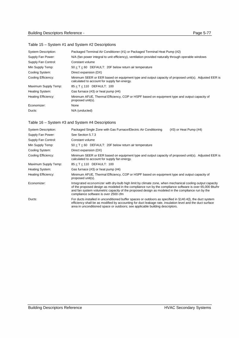
Building Descriptors Reference - Page 5-77
Building Descriptors Reference HVAC Secondary Systems
Table 15 – System #1 and System #2 Descriptions
System Description: Packaged Terminal Air Conditioner (#1) or Packaged Terminal Heat Pump (#2)
Supply Fan Power: N/A (fan power integral to unit efficiency), ventilation provided naturally through operable windows
Supply Fan Control: Constant volume
Min Supply Temp: 50 < T < 60 DEFAULT: 20F below return air temperature
Cooling System: Direct expansion (DX)
Cooling Efficiency: Minimum SEER or EER based on equipment type and output capacity of proposed unit(s). Adjusted EER iscalculated to account for supply fan energy.
Maximum Supply Temp: 85 < T < 110 DEFAULT: 100
Heating System: Gas furnace (#3) or heat pump (#4)
Heating Efficiency: Minimum AFUE, Thermal Efficiency, COP or HSPF based on equipment type and output capacity ofproposed unit(s).
Economizer: None
Ducts: N/A (unducted)
Table 16 – System #3 and System #4 Descriptions
System Description: Packaged Single Zone with Gas Furnace/Electric Air Conditioning (#3) or Heat Pump (#4)
Supply Fan Power: See Section 5.7.3
Supply Fan Control: Constant volume
Min Supply Temp: 50 < T < 60 DEFAULT: 20F below return air temperature
Cooling System: Direct expansion (DX)
Cooling Efficiency: Minimum SEER or EER based on equipment type and output capacity of proposed unit(s). Adjusted EER iscalculated to account for supply fan energy.
Maximum Supply Temp: 85 < T < 110 DEFAULT: 100
Heating System: Gas furnace (#3) or heat pump (#4)
Heating Efficiency: Minimum AFUE, Thermal Efficiency, COP or HSPF based on equipment type and output capacity ofproposed unit(s).
Economizer: Integrated economizer with dry-bulb high limit by climate zone, when mechanical cooling output capacityof the proposed design as modeled in the compliance run by the compliance software is over 65,000 Btu/hrand fan system volumetric capacity of the proposed design as modeled in the compliance run by thecompliance software is over 2500 cfm
Ducts: For ducts installed in unconditioned buffer spaces or outdoors as specified in §140.4(l), the duct systemefficiency shall be as modified by accounting for duct leakage rate, insulation level and the duct surfacearea in unconditioned space or outdoors; see applicable building descriptors.

Building Descriptors Reference - Page 5-78
Building Descriptors Reference HVAC Secondary Systems
Table 17 – System #5 Description
System Description: Packaged VAV with Boiler and Reheat
Supply Fan Power: See Section 5.7.3
Supply Fan Control: Individual VAV supply fan with less than 10 hp:
VAV - forward curved fan with discharge damper
Individual VAV supply fan greater than or equal to 10 hp:
VAV - variable speed drive
Return Fan Control: Same as supply fan
Minimum Supply Temp: 50 < T < 60 DEFAULT: 20F below return air temperature
Cooling System: Direct expansion (DX)
Cooling Efficiency: Minimum efficiency based on average proposed output capacity of equipment unit(s)
Maximum Supply Temp: 90 < T < 110 DEFAULT: 105
Heating System: Gas boiler
Hot Water Pumping System Variable flow (2-way valves) riding the pump curve
Heating Efficiency: Minimum efficiency based on average proposed output capacity of equipment unit(s)
Economizer: Integrated dry bulb economizer, when mechanical cooling output capacity of the proposed design asmodeled in the compliance run by the compliance software is over 75,000 Btu/hr and fan system volumetriccapacity of the proposed design as modeled in the compliance run by the compliance software is over 2500cfm
Table 18 – System #6 Description
System Description: Chilled Water VAV With Reheat
Supply Fan Power: See Section 5.7.3
Supply Fan Control: Individual VAV supply fan with less than 10 hp::
VAV - forward curved fan with discharge damper
Individual VAV supply fan with greater than or equal to 10 hp:
VAV - variable speed drive
Return Fan Control: Same as supply fan
Minimum Supply Temp: 50 < T < 60 DEFAULT: 20F below return air temperature
Cooling System: Chilled water
Chilled Water PumpingSystem
Variable flow (2-way valves) with a VSD on the pump if three or more fan coils or air handlers. Constantvolume flow with water temperature reset control if less than three fan coils or air handlers. Reset supplypressure by demand if proposed system has DDC controls.
Cooling Efficiency: Minimum efficiency based on average proposed output capacity of equipment unit(s)
Maximum Supply Temp: 90 < T < 110 DEFAULT: 105
Heating System: Gas boiler
Hot Water PumpingSystem
Variable flow (2-way valves) riding the pump curve if three or more fan coils or air handlers. Constantvolume flow with water temperature reset control if less than three fan coils or air handlers. Reset supplypressure by demand if proposed system has DDC controls.
Heating Efficiency: Minimum efficiency based on average proposed output capacity of equipment unit(s)
Economizer: Integrated dry bulb economizer, when mechanical cooling output capacity of the proposed design asmodeled in the compliance run by the compliance software is over 75,000 Btu/hr and fan systemvolumetric capacity of the proposed design as modeled in the compliance run by the compliance softwareis over 2500 cfm

Building Descriptors Reference - Page 5-79
Building Descriptors Reference HVAC Secondary Systems
Table 19 – System #7,8 Description
System Description: Single-zone VAV System
Supply Fan Power: See Section 5.7.3
Supply Fan Control Two-speed, with fan power at low stage at 40 percent or lower power at 66% flow
Minimum Supply Temp: 50 < T < 60 DEFAULT: 20F below return air temperature
Supply Temp Control: Supply temperature setpoint reset up 5°F on low cooling stage.
Supply air temperature setpoint shall be linearly reset from minimum at 50% cooling load and above tomaximum at 0% cooling load. Fan volume shall be linearly reset from 100% air flow at 100% cooling load tominimum air flow at 50% cooling load and below. Minimum fan volume setpoint shall be 50%. (this iseffectively an “airflow first” sequence”)
Cooling System: Direct expansion
Cooling Efficiency: Minimum efficiency based on the proposed output capacity of specific equipment unit(s)
Cooling Stages: Two, with 50% total capacity at low cooling stage
Maximum Supply Temp: 90 < T < 110 DEFAULT: 100
Heating System: Gas furnace or heat pump (system 8)
Hot Water Pumping System Variable flow (2-way valves) riding the pump curve if three or more fan coils. Constant volume flow withwater temperature reset control if less than three fan coils. Reset supply pressure by demand if proposedsystem has DDC controls.
Heating Efficiency: Minimum efficiency based on the proposed output capacity of specific equipment unit(s)
Economizer: Integrated dry bulb economizer with dry-bulb high limit based on climate zone
Table 20 – System #9 Description
System Description: Heating and ventilation only system
Supply Fan Power: See fan power details; 0.8 W/cfm baseline
Supply Fan Control Constant Volume
Minimum Supply Temp: N/A
Cooling System: None
Cooling Efficiency: N/A
Maximum Supply Temp: 90 < T < 110 DEFAULT: 100
Heating System: Gas furnace
Hot Water Pumping System N/A
Heating Efficiency: Minimum efficiency based on the proposed output capacity of specific equipment unit(s)
Economizer: TBD
Table 21 – System #10 Description
System Description: Computer room air handler (CRAH)
Supply Fan Power: See fan power details; 0.49 W/cfm baseline
Supply Fan Control variable speed drive. Fan power ratio at part load = speed ratio ^3 (e.g. 12.5% of design power at 50%speed).
Minimum Supply Temp: 60F
Cooling System: Chilled water
Cooling Efficiency: Same as System #6 (Built-up VAV)
Maximum Supply Temp: 80
Heating System: None
Economizer: TBD
Supply Temp Control: Supply air temperature setpoint shall be linearly reset from minimum at 50% cooling load and above tomaximum at 0% cooling load. Fan volume shall be linearly reset from 100% air flow at 100% cooling load tominimum air flow at 50% cooling load and below. Minimum fan volume setpoint shall be 50%. (this iseffectively an “airflow first” sequence”)

Building Descriptors Reference - Page 5-80
Building Descriptors Reference HVAC Secondary Systems
Table 22 – System #11 Description
System Description: Computer room air conditioner (CRAC)
Supply Fan Power: 0.49 W/cfm at design flow (see equipment sizing) where economizer is required, 0.39 W/cfm whereeconomizer is not required.
Supply Fan Control Constant speed if total cooling capacity for the room < = 5 tons, otherwise: variable speed drive. Fanpower ratio at part load = speed ratio ^3 (e.g. 12.5% of design power at 50% speed).
Return Fan Control: No return fans
Minimum Supply Temp: 60F
Cooling System: Air-cooled DX
Cooling Capacity: Equipment sizing CFM and cooling capacity sized at 120% of the calculated room load. One fan system perroom.
Cooling Efficiency: Minimum packaged air conditioner efficiency based on calculated total cooling capacity for each room● If cooling capacity > 20 tons then use 10 ton min efficiency ● If cooling capacity <20 tons then use capacity/2 min efficiency
Maximum Supply Temp: 80
Heating System: None
Economizer: No economizer if total cooling capacity for the room < 5 tons and building does not have anyeconomizers, otherwise: Integrated differential dry bulb economizer
Supply Temp Control: VAV: Supply air temperature setpoint shall be linearly reset from minimum at 50% cooling load andabove to maximum at 0% cooling load. Fan volume shall be linearly reset from 100% air flow at 100%cooling load to minimum air flow at 50% cooling load and below. Minimum fan volume setpoint shall be50%. (this is effectively an “airflow first” sequence”)CV: supply air temperature setpoint modulates to meet the load.
5.7.1 Basic System Information
HVAC System Name
All system types
A unique descriptor for each HVAC System
Text, unique
When applicable, this input should match the tags that are used on the plans.
None
System Type
All system types
A unique descriptor which identifies the following attributes of an HVAC System:
Number of air decks (one to three);
Constant or variable air flow;
Type of terminal device; and
Fan configuration for multiple deck systems.
List from the choices below
List
Applicability
Units
Input Restrictions
Standard Design
Applicability
Definition
Units
Input Restrictions
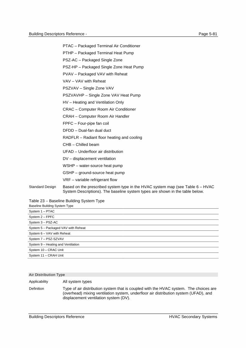
Building Descriptors Reference - Page 5-81
Building Descriptors Reference HVAC Secondary Systems
PTAC – Packaged Terminal Air Conditioner
PTHP – Packaged Terminal Heat Pump
PSZ-AC – Packaged Single Zone
PSZ-HP – Packaged Single Zone Heat Pump
PVAV – Packaged VAV with Reheat
VAV – VAV with Reheat
PSZVAV – Single Zone VAV
PSZVAVHP – Single Zone VAV Heat Pump
HV – Heating and Ventilation Only
CRAC – Computer Room Air Conditioner
CRAH – Computer Room Air Handler
FPFC – Four-pipe fan coil
DFDD – Dual-fan dual duct
RADFLR – Radiant floor heating and cooling
CHB – Chilled beam
UFAD – Underfloor air distribution
DV – displacement ventilation
WSHP – water-source heat pump
GSHP – ground-source heat pump
VRF – variable refrigerant flow
Based on the prescribed system type in the HVAC system map (see Table 6 – HVACSystem Descriptions). The baseline system types are shown in the table below.
Table 23 – Baseline Building System TypeBaseline Building System Type
System 1 – PTAC
System 2 – FPFC
System 3 – PSZ-AC
System 5 – Packaged VAV with Reheat
System 6 – VAV with Reheat
System 7 – PSZ-SZVAV
System 9 – Heating and Ventilation
System 10 – CRAC Unit
System 11 – CRAH Unit
Air Distribution Type
All system types
Type of air distribution system that is coupled with the HVAC system. The choices are(overhead) mixing ventilation system, underfloor air distribution system (UFAD), anddisplacement ventilation system (DV).
Standard Design
Applicability
Definition

Building Descriptors Reference - Page 5-82
Building Descriptors Reference HVAC Secondary Systems
List: Mixing, UFAD, DV
As designed
Mixing
Thermal zone List
All system types
Comprehensive list of all thermal zones served by a given HVAC system.
None
Same as the proposed design
As designed
Total Cooling Capacity
All system types
The installed cooling capacity of the project. This includes all:
Chillers;
Built-up DX; and,
Packaged cooling units.
Cooling tons (12,000 Btu/h per ton)
As designed. This could be calculated by the program from the proposed designbuilding description or a separate load calculation may be used. Unmet load hours forthe simulation shall not exceed 300 annually. Weather conditions used in sizing runsshall be based on 0.5% dry-bulb and 1% wet-bulb cooling design temperatures.
Autosize. The cooling capacity shall be oversized by 15%. If the number of unmet loadhours exceeds 300, increase the cooling capacity according to the procedures inChapter 2.
5.7.2 System Controls
5.7.2.1 Schedules
Cooling Schedule
All cooling systems
A schedule that represents the availability of cooling
Data structure: schedule, on/off
For California Compliance and Reach calculations, the fan schedules from Appendix5.4B shall be used as a default for cooling availability. When schedules other than thedefault values are used, supporting documentation shall be required. The coolingavailability schedule shall be consistent with the supply fan schedule and thermostatschedules to reduce the likelihood of unmet load hours.
Same as the proposed design
Units
Input Restrictions
Standard Design
Applicability
Definition
Units
Standard Design
Input Restrictions
Applicability
Definition
Units
Input Restrictions
Standard Design
Applicability
Definition
Units
Input Restrictions
Standard Design

Building Descriptors Reference - Page 5-83
Building Descriptors Reference HVAC Secondary Systems
Heating Schedule
All systems
A schedule that represents the availability of heating
Data structure: schedule, on/off
For California Compliance and Reach calculations, the schedules from Appendix 5.4Bshall be used as a default. When schedules other than the default values are used,supporting documentation shall be required. The heating availability schedule shall beconsistent with the supply fan schedule.
Same as the proposed design
Air-Handler Schedule
All systems that do not cycle with loads
A schedule that indicates when the air handler operates continuously
Data structure: schedule, on/off
For the purpose of Compliance and Reach calculations, the fan schedule is defaultedto the applicable schedule from Appendix 5.4B. One of the schedules from Appendix5.4B, shall be used as a default. When schedules other than the default values areused, supporting documentation shall be required.
When a fan system serves several occupancies, the fan schedule must remain ON toserve the operating hours of each occupancy.
Same as the proposed design
Air Handler Fan Cycling
All fan systems
This building descriptor indicates whether the system supply fan operates continuouslyor cycles with building loads. The fan systems in most commercial buildings operatecontinuously.
List: Continuous or Cycles with loads
Continuous fan operation during occupied periods is a prescribed input
For natural ventilation systems, an air conditioner is modeled in the proposed designeven though one is not specified for the proposed design. In this case, the air handlercontrol is Cycles with loads. .
Same as proposed design
Optimal Start Control
Systems with the control capability for flexible scheduling of system start time basedon building loads.
Optimal start control adjusts the start time of the HVAC unit such that the space isbrought to setpoint just prior to occupancy. This control strategy modifies the heating,cooling, and fan schedules.
Boolean (Yes/No)
No (not allowed)
applicable
Applicability
Definition
Units
Input Restrictions
Standard Design
Applicability
Definition
Units
Input Restrictions
Standard Design
Applicability
Definition
Units
Input Restrictions
Standard Design
Applicability
Definition
Units
Input Restrictions
Standard Design

Building Descriptors Reference - Page 5-84
Building Descriptors Reference HVAC Secondary Systems
Night-Cycle HVAC Fan Control
All systems
The control of an HVAC system that is triggered by the heating or cooling temperaturesetpoint for thermal zones during periods when the heating, cooling and fan systemsare scheduled to be off. For this control, the space is controlled to the setback or setuptemperature only; this control is not equivalent to a night purge control. The choicesare:
Cycle on call from any zone
Cycle on call from the primary control zone
Stay off
Cycle zone fans only (for systems with fan-powered boxes) Restart fans belowgiven ambient temperature.
None
As designed. Outside air dampers are set to closed during night-cycle control.
Same as proposed
5.7.2.2 Cooling Control
Cooling Supply Air Temperature
Applicable to all systems
The supply air temperature setpoint at design cooling conditions
Degrees Fahrenheit (°F)
As designed
15F below the space temperature setpoint for interior zones; for all other zones,
20°F below the space temperature setpoint
Cooling Supply Air Temperature Control
Any cooling system
The method of controlling the supply air temperature. Choices are:
Fixed (constant)
Reset by warmest zone
Reset by outside air dry-bulb temperature
Scheduled setpoint
Staged setpoint (for Single Zone VAV and DX with multiple stages)
List (see above)
For baseline building systems 1 through 4 and 11, the SAT control is fixed. Forsystems 5 through 8 and 10, the SAT control shall be reset by warmest zone. Forsystem 9 (heating and ventilation) this input is not applicable.
Applicability
Definition
Units
Input Restrictions
Standard Design
Applicability
Definition
Units
Input Restrictions
Standard Design
Applicability
Definition
Units
Input Restrictions
Standard Design

Building Descriptors Reference - Page 5-85
Building Descriptors Reference HVAC Secondary Systems
Cooling Reset Schedule by OSA
When the proposed design resets SAT by outside air dry-bulb temperature
A linear reset schedule that represents the SAT setpoint as a function of outdoor airdry-bulb temperature. This schedule is defined by the following data points (see Figure7):
The coldest cooling supply air temperature
The corresponding (hot) outdoor air dry-bulb setpoint
The warmest cooling supply air temperature
The corresponding (cool) outdoor air dry-bulb setpoint
55
56
57
58
59
60
61
62
63
64
65
0 20 40 60 80 100 120
OAT
SA
TS
etp
oin
t
Figure 7 – SAT Cooling Setpoint Reset based on Outdoor Air Temperature (OAT)
Data structure (two matched pairs of SAT and OAT, see above)
As Designed.
For California Compliance and Reach, the schedule defaults to:
Supply Air High = Supply Air Low + 5
Supply Low = (greater of SAT and 50F)
Outside High = 80°F
Outside Low = 60°F
Applicable for baseline building systems 5 and 6. For these systems, the minimumSAT shall be equal to the design conditions SAT when OAT is equal to or greater than80 F. The maximum SAT shall be 5 F greater than the minimum when the OAT is 60 For less.
Applicability
Definition
Units
Input Restrictions
Standard Design
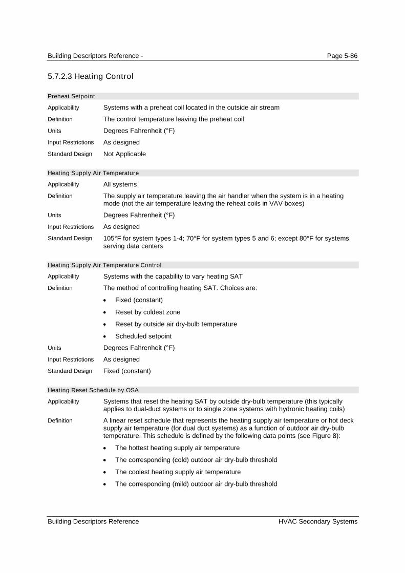
Building Descriptors Reference - Page 5-86
Building Descriptors Reference HVAC Secondary Systems
5.7.2.3 Heating Control
Preheat Setpoint
Systems with a preheat coil located in the outside air stream
The control temperature leaving the preheat coil
Degrees Fahrenheit (°F)
As designed
Not Applicable
Heating Supply Air Temperature
All systems
The supply air temperature leaving the air handler when the system is in a heatingmode (not the air temperature leaving the reheat coils in VAV boxes)
Degrees Fahrenheit (°F)
As designed
105°F for system types 1-4; 70°F for system types 5 and 6; except 80°F for systemsserving data centers
Heating Supply Air Temperature Control
Systems with the capability to vary heating SAT
The method of controlling heating SAT. Choices are:
Fixed (constant)
Reset by coldest zone
Reset by outside air dry-bulb temperature
Scheduled setpoint
Degrees Fahrenheit (°F)
As designed
Fixed (constant)
Heating Reset Schedule by OSA
Systems that reset the heating SAT by outside dry-bulb temperature (this typicallyapplies to dual-duct systems or to single zone systems with hydronic heating coils)
A linear reset schedule that represents the heating supply air temperature or hot decksupply air temperature (for dual duct systems) as a function of outdoor air dry-bulbtemperature. This schedule is defined by the following data points (see Figure 8):
The hottest heating supply air temperature
The corresponding (cold) outdoor air dry-bulb threshold
The coolest heating supply air temperature
The corresponding (mild) outdoor air dry-bulb threshold
Applicability
Definition
Units
Input Restrictions
Standard Design
Applicability
Definition
Units
Input Restrictions
Standard Design
Applicability
Definition
Units
Input Restrictions
Standard Design
Applicability
Definition

Building Descriptors Reference - Page 5-87
Building Descriptors Reference HVAC Secondary Systems
60
70
80
90
100
110
120
0 10 20 30 40 50 60 70 80 90
OAT
SA
TS
etp
oin
t
Figure 8 – Example of SAT heating setpoint reset based on outdoor air temperature (OAT).
Data structure (°F)
As designed
Not applicable
5.7.2.4 Night Purge
Night purge controls are not allowed for Title 24 compliance or reach.
Night Purge Availability Schedule
Systems that operate the fans for nighttime purge of heat gains
A schedule which represents the availability of night purge controls.
Data structure: schedule, on/off
Not applicable
Not applicable
Night Purge Control
Systems that operate the fans for nighttime purge of heat gains
The control strategy for operation of nighttime purge. The control strategy may takeaccount of indoor temperature, season, indoor temperature and other factors.
Data structure
Not applicable (Night Purge Control is not allowed in the model)
Not applicable
Units
Input Restrictions
Standard Design
Applicability
Definition
Units
Input Restrictions
Standard Design
Applicability
Definition
Units
Input Restrictions
Standard Design

Building Descriptors Reference - Page 5-88
Building Descriptors Reference HVAC Secondary Systems
Night Purge Fan Ratio
Systems that operate the fans for nighttime purge of heat gains
The ratio of fan speed for a night purge cycle.
Ratio
Not applicable
Not applicable
5.7.3 Fan Systems
5.7.3.1 Baseline Building Fan System Summary
The baseline building fan system is summarized in this section. See Table 5 – HVAC System Map for theHVAC baseline building system mapping.
Total baseline building fan system power for the baseline building fan systems is given in the followingsection. This brake horsepower includes the supply fan, the return fan, and exhaust fans. Exhaust fansinclude kitchen hoods, toilets, fume hoods, and other miscellaneous fans that operate at designconditions.
When the proposed design has exhaust fans (toilets or kitchens), or fume hood exhaust systems, thebaseline building has the same systems.
Table 24 – Building Descriptor Applicability for Fan Systems
Inputs Supply Fan Return/Relief Fan Exhaust Fans (Hoods)
Modeling Method Same as supply
Air Rated Capacity
Plenum Zone X X
Return Air Path X X
Fan Control Method Same as supply
Brake Horsepower
Static Pressure
Fan Efficiency
Motor Efficiency
Fan Position X X
Motor Position X
Part-Load Power Curve
Fan KW
5.7.3.2 Supply Fans
Fan System Modeling Method
All fan systems
Software commonly models fans in three ways. The simple method is for the user to
Applicability
Definition
Units
Input Restrictions
Standard Design
Applicability
Definition
Building Descriptors Reference - Page 5-89
Building Descriptors Reference HVAC Secondary Systems
enter the electric power per unit of flow (W/cfm). This method is commonly used forunitary equipment and other small fan systems. A more detailed method is to modelthe fan as a system whereby the static pressure, fan efficiency, part-load curve, andmotor efficiency are specified at design conditions. A third method is to specify brakehorsepower at design conditions instead of fan efficiency and static pressure. This is avariation of the second method whereby brake horsepower is specified in lieu of staticpressure and fan efficiency. The latter two methods are commonly used for VAV andother larger fan systems.
List: power-per-unit-flow, static pressure or brake horsepower
As designed. The power-per-unit-flow method shall be used when no fan performancedata is available for the proposed design cooling system, e.g. only EER or SEER areavailable.
The baseline building shall use the static pressure method.
Supply Fan Design Air Rated Capacity
All fan systems
The design air flow rate of the supply fan(s) at design conditions. This buildingdescriptor sets the 100% point for the fan part-load curve.
cfm
As designed. This input should be at least as great as the sum of the design air flowspecified for each of the thermal zones that are served by the fan system. For multipledeck systems, a separate entry should be made for each deck.
The program shall automatically size the air flow at each thermal zone to meet theloads. The design air flow rate calculation shall be based on a 20°F temperaturedifferential between the supply air and the return air for exterior zones and a 15°Ftemperature differential for interior zones. The design supply air flow rate is the largerof the flow rate required to meet space conditioning requirements and the requiredventilation flow rate. (The ventilation requirements may dictate supply air flow raterequirements for laboratory spaces and other spaces with special processrequirements.) The supply fan design air flow rate shall be the sum of the calculateddesign air flow for the thermal zones served by the fan system.
Fan Control Method
All fan systems
A description of how the supply (and return/relief) fan(s) are controlled. The optionsinclude:
Constant volume
Variable-flow, inlet or discharge dampers
Variable-flow, inlet guide vanes
Variable-flow, variable speed drive (VSD)
Variable-flow, variable pitch blades
Variable-flow, other
Two-speed
Constant volume, cycling (fan cycles with heating and cooling)
Units
Input Restrictions
Standard Design
Applicability
Definition
Units
Input Restrictions
Standard Design
Applicability
Definition
Units

Building Descriptors Reference - Page 5-90
Building Descriptors Reference HVAC Secondary Systems
List (see above)
As designed
Applicable to variable air volume systems
Based on the prescribed system type. Refer to the HVAC System Map in Error!Reference source not found..
Table 25 – Baseline Building Fan Control MethodBaseline building System Fan Control Method
System 1 – PTAC Constant volume (Two-speed for systems greater than 72kBtu/h baseline cooling capacity)
System 2 – PTHP Constant volume (Two-speed for systems greater than 72 kBtu/hbaseline cooling capacity,)
System 3 – PSZ-AC Constant volume (Two-speed for systems greater than 72 kBtu/hbaseline cooling capacity,)
System 4 – PSZ-HP Constant volume(Two-speed for systems greater than 72 kBtu/hbaseline cooling capacity)
System 5 – Packaged VAV with Reheat Variable-flow, variable speed drive (VSD)
System 6 – VAV with Reheat Variable-flow, variable speed drive (VSD)
System 7 – PSZ, Single Zone VAV Variable-flow, two-speed drive (VSD)
System 8 – PSZ, Single Zone VAV, HP Variable-flow, two-speed drive (VSD)
System 9 – Heating and Ventilation Constant volume
System 10 – CRAH Units Variable-flow, variable speed drive (VSD)*
System 11 – CRAC Units Variable-flow, variable speed drive (VSD)*
* For CRAH Units, fan volume shall be linearly reset from 100% air flow at 100% cooling load tominimum airflow at 50% cooling load and below.
Supply Fan Brake Horsepower
All fan systems, except those specified using the power-per-unit-flow method
The design shaft brake horsepower of the supply fan(s). This input does not need tobe supplied if the Supply Fan kW is supplied.
Horsepower (hp)
As designed. If this building descriptor is specified for the proposed design, then theStatic Pressure and Fan Efficiency are not.
Series-powered fans that operate at design conditions should be included in theproposed fan brake horsepower calculations. Fans for parallel fan-powered boxes arenot included.
Not applicable
Supply Fan Static Pressure
All fan systems, except those specified using the power-per-unit-flow method
The design static pressure for the supply fan. This is important for both fan electricenergy usage and duct heat gain calculations.
Inches of water column (in. H20)
Input Restrictions
Standard Design
Applicability
Definition
Units
Input Restrictions
Standard Design
Applicability
Definition
Units
Input Restrictions
Building Descriptors Reference - Page 5-91
Building Descriptors Reference HVAC Secondary Systems
As designed. The design static pressure for the supply fan does not need to bespecified if the supply fan brake horsepower (bhp) is specified.
Not applicable. When Static Pressure and Fan Efficiency are entered for the proposeddesign, the baseline building shall use Brake Horsepower.
The standard design is defined by the following table:
Airflow Single Zone, 6stories or less
Single Zone, 6stories or less
Multiple Zone, lessthan 6 stories
Multiple Zone,greater than 6stories
<2000 cfm 2.5” 3.0” 3.0” 3.5”
2000 cfm – 10,000cfm
3.0” 3.5” 3.5” 4.0”
>10,000 cfm 3.5” 4.0” 4.0” 4.5”
An additional pressure drop allowance is available for special filtration requirementsonly for specific processes such as clean rooms. See Process and Filtration PressureDrop for details.
Supply Fan Efficiency
All fan systems, except those specified using the power-per-unit-flow method
The efficiency of the fan at design conditions; this is the static efficiency and does notinclude motor losses.
Unitless
As designed. The supply fan efficiency does not need to be specified if the supply fanbrake horsepower (bhp) is specified.
The baseline Supply Fan Efficiency shall be 50% if the design supply air flow is lessthan 2000 cfm, 60% if the design supply air flow is between 2000 cfm and 10,000 cfm,or 62% if the design supply airflow is greater than 10,000 cfm.
Supply Motor Efficiency
All supply fans, except those specified using the power-per-unit-flow method
The full-load efficiency of the motor serving the supply fan
Unitless
As designed. Not applicable when the power-per-unit-flow method is used.
The motor efficiency is determined from Table 26 for the next motor size greater thanthe bhp.
Standard Design
Applicability
Definition
Units
Input Restrictions
Standard Design
Applicability
Definition
Units
Input Restrictions
Standard Design

Building Descriptors Reference - Page 5-92
Building Descriptors Reference HVAC Secondary Systems
Table 26 – Minimum Nominal Efficiency for Electric Motors (%)
Motor HorsePower
1 85.5
1.5 86.5
2 86.5
3 89.5
5 89.5
7.5 91.7
10 91.7
15 92.4
20 93.0
25 93.6
30 93.6
40 94.1
50 94.5
60 95.0
75 95.4
100 95.4
125 95.4
150 95.8
200 96.2
250 96.2
300 96.2
350 96.2
400 96.2
450 96.2
500 96.2
Fan Position
All supply fans
The position of the supply fan relative to the cooling coil. The configuration is eitherdraw through (fan is downstream of the coil) or blow through (fan is upstream of thecoil).
List (see above)
As designed.
Draw through
Motor Position
All supply fans
The position of the supply fan motor relative to the cooling air stream. The choices are:in the air stream or out of the air stream.
List (see above)
Applicability
Definition
Units
Input Restrictions
Standard Design
Applicability
Definition
Units

Building Descriptors Reference - Page 5-93
Building Descriptors Reference HVAC Secondary Systems
As designed.
In the air stream
Fan Part-Flow Power Curve
All variable flow fan systems
A part-load power curve which represents the percentage full-load power draw of thesupply fan as a function of the percentage full-load air flow. The curve is typicallyrepresented as a quadratic equation with an absolute minimum power draw specified.
Unitless ratio
As designed. The user shall not be able to select VSD with Static Pressure Reset if thebuilding does not have DDC controls to the zone level. The default fan curve shall beselected from Equation (4) and Table 27 for the type of fan specified in the proposeddesign.
(4)
PowerMinPLR
FanRatiodFanRatiocFanRatiobaPLR
ofGreater
32
where
PLR Ratio of fan power at part load conditions to full load fan power
PowerMin Minimum fan power
FanRatio Ratio of cfm at part-load to full-load cfm
a, b, c and d Constants from Table 27 below
Table 27 – Fan Curve Default ValuesFan Type - Control Type A B c d %PowerMin
AF or BI riding the curvea 0.1631 1.5901 -0.8817 0.1281 70%
AF or BI with inlet vanesa 0.9977 -0.659 0.9547 -0.2936 50%
FC riding the curvea 0.1224 0.612 0.5983 -0.3334 30%
FC with inlet vanesa 0.3038 -0.7608 2.2729 -0.8169 30%
Vane-axial with variable pitch bladesa 0.1639 -0.4016 1.9909 -0.7541 20%
Any fan with VSD ()b 0.0013 0.1470 0.9506 -0.0998 20%
VSD with static pressure resetc -0.0031 0.0991 1.0268 -0.1128 20%
Data Sources:a. ECB Compliance Supplement, public review draft, Version 1.2, March 1996, but adjusted to be relatively consistent withthe curve specified in the PRM.b. The fan curve for VSD is specified in Table G3.1.3.15c. Advanced VAV System Design Guide, California Energy Commission, CEC Publication 500,-03-082 A-11, April 2005, butadjusted to be relatively consistent with the curve specified in the PRM..
Not applicable for baseline building systems 1-4. The curve VSD with static pressurereset fans shall be used for baseline building systems 5, 6, 10 and 11 . For systems7,8 and 9 the baseline is not applicable.
Supply Fan Power Index
Fan systems that use the power-per-unit-flow method
Input Restrictions
Standard Design
Applicability
Definition
Units
Input Restrictions
Standard Design
Applicability

Building Descriptors Reference - Page 5-94
Building Descriptors Reference HVAC Secondary Systems
The supply fan power per unit of flow.
kW/cfm
As designed or specified in the manufacturers’ literature. For units with rated totalcooling capacities less than 120,000 Btu/h, the user may default to a value calculatedas follows:
(5)
000,30365.0 rated
kw
QFan
where
Fankw The supply fan power (kW)
Qrated The rated total cooling capacity (Btu/h)
Not applicable
Process and Filtration Pressure Drop
Any system with special requirements for filtration or other process requirements
Additional system pressure drop related to application-specific filtration requirementsor other process requirements. Special documentation requirements may apply.
List
Default is 0. Special documentation is required to claim any credit for filtration or otherprocess requirements. Filtration shall be associated with process requirements (suchas clean room or hospital areas).
0 (not applicable)
5.7.3.3 Return/Relief Fans
The baseline building has a return fan when the baseline building system is type 3 through 8 and theproposed design has a return fan.
Plenum Zone
Any system with return ducts or return air plenum
A reference to the thermal zone that serves as return plenum or where the return ductsare located
Text, unique
As designed
Applicable when the baseline building has a return fan. Same as the proposed designwhen the proposed design has a plenum, otherwise, the return air ducts are assumedto be located in the space.
Return Air Path
Any system with return ducts or return air plenum
Definition
Units
Input Restrictions
Standard Design
Applicability
Definition
Units
Input Restrictions
Standard Design
Applicability
Definition
Units
Input Restrictions
Standard Design
Applicability
Definition

Building Descriptors Reference - Page 5-95
Building Descriptors Reference HVAC Secondary Systems
Describes the return path for air. This can be one of the following: ducted return;plenum return; or direct-to-unit.
List (see above)
As designed
Applicable when the baseline building has a return fan. For baseline building systems1 and 2, the return air path shall be direct-to-unit. For baseline building systems 3through 11 and when the proposed design is direct-to-unit, the baseline building shallbe ducted return, otherwise the baseline building return air path shall be same asproposed design.
Return/Relief Air Rated Capacity
All systems with a return or relief fan
The design air flow fan capacity of the return or relief fan(s). This sets the 100% fanflow point for the part-load curve (see below).
cfm
As designed
Applicable when the baseline building has a return fan. The return fan air RatedCapacity shall be equal to the baseline building supply fan capacity less exhaust airflow.
Return/Relief Fan Brake Horsepower
Any system with return or relief fans that uses the brake horsepower method
The design shaft brake horsepower of the return/relief fan(s)
Brake horsepower (bhp)
As designed
The bhp of the return fan shall be the system fan power index (W/cfm) multiplied bythe supply airflow, the motor efficiency from ACM Table N2-20, and the return fanratio. In other words, brake horsepower is allocated in proportion to the proposeddesign.
Return/Relief Design Static Pressure
Any system with return or relief fans that uses the static pressure method
The design static pressure for return fan system. This is important for both fan electricenergy usage and duct heat gain calculations.
Inches of water column (in. H20 gauge)
As designed. The design static pressure for the return fan does not need to bespecified if the return fan brake horsepower (bhp) is specified.
For fans with design airflow less than 10,000 cfm, the static pressure is 0.75”.
For fans with design airflow rate 10,000 cfm or greater, the static pressure is 1.0”
Return/Relief Fan Efficiency
Any system with return or relief fans that uses the static pressure method
Units
Input Restrictions
Standard Design
Applicability
Definition
Units
Input Restrictions
Standard Design
Applicability
Definition
Units
Input Restrictions
Standard Design
Applicability
Definition
Units
Input Restrictions
Standard Design
Applicability
Building Descriptors Reference - Page 5-96
Building Descriptors Reference HVAC Secondary Systems
The efficiency of the fan at design conditions; this is the static efficiency and does notinclude the efficiency loss of the motor.
Unitless
As designed. The return/relief fan efficiency does not need to be specified if the returnfan brake horsepower (bhp) is specified.
Not applicable. When Static Pressure and Fan Efficiency are entered for the proposeddesign, the baseline building shall use Brake Horsepower.
For design airflow less than 10,000 cfm, 40%. For design airflow 10,000 cfm orgreater, 50%.
Return/Relief Motor Efficiency
All return fans, except those specified using the power-per-unit-flow method
The full-load efficiency of the motor serving the supply fan
Unitless
As designed. Not applicable when the power-per-unit-flow method is used.
From ACM Table 26
Motor Position
All return fans
The position of the supply fan motor relative to the cooling air stream. The choices are:in the air stream or out of the air stream.
List (see above)
As designed.
In the air stream
Fan Part-Flow Power Curve
All return fans for variable flow fan systems.
A part-load power curve which represents the percentage full-load power draw of thesupply fan as a function of the percentage full-load air flow.
Unitless ratio
As designed. The default fan curve shall be selected from Equation (4) and Table 27for the type of fan specified in the proposed design.
Not applicable for baseline building systems 1-4. The curve for VSD fans shall be usedfor baseline building systems 5-6, and 10 or 11 that have a return/relief fan. This is notapplicable for baseline building systems 7, 8, 9.
Return/Relief Fan Power Index
Any system with a return fan
The supply fan power per unit of flow
kW/cfm
As specified in the manufacturers’ literature
Definition
Units
Input Restrictions
Standard Design
Applicability
Definition
Units
Input Restrictions
Standard Design
Applicability
Definition
Units
Input Restrictions
Standard Design
Applicability
Definition
Units
Input Restrictions
Standard Design
Applicability
Definition
Units
Input Restrictions
Standard Design

Building Descriptors Reference - Page 5-97
Building Descriptors Reference HVAC Secondary Systems
Not applicable
5.7.3.4 Exhaust Fan Systems
Exhaust fans include toilet exhaust and kitchen exhaust. Fume hoods in laboratories and other spacesare not included. Some systems typically operate at constant flow, while flow varies for other systemsdepending on, for instance, the position of the sash for fume hoods. Exhaust fan flow is specified andscheduled for each thermal zone. An exhaust fan system may serve multiple thermal zones. The baselinebuilding has exhaust fans when the proposed design has exhaust fans. The exhaust air flow is the samefor the baseline building and the proposed design.
Note: exhaust fans serving laboratories shall be modeled as a plug load in an unconditioned space equalto the scheduled motor horsepower of the exhaust fans.
Exhaust Fan Name
All exhaust systems serving multiple thermal zones
A unique descriptor for each exhaust fan. This should be keyed to the constructiondocuments, if possible, to facilitate plan checking. Exhaust rates and schedules at thethermal zone level refer to this name.
Text, unique
Where applicable, this should match the tags that are used on the plans.
The baseline building will have an exhaust system that corresponds to the proposeddesign. The name can be identical to that used for the proposed design or some otherappropriate name may be used.
Exhaust Fan System Modeling Method
All exhaust fan systems
Software commonly models fans in three ways. See definition for supply systemmodeling method.
List: power-per-unit-flow, static pressure or brake horsepower
As designed
The baseline building shall use the static pressure method.
Exhaust Fan Rated Capacity
All exhaust systems
The rated design air flow rate of the exhaust fan system. This building descriptordefines the 100% flow case for the part-flow curve. Actual air flow is the sum of theflow specified for each thermal zone, as modified by the schedule for each thermalzone.
cfm
As designed
Same as proposed design
Fan Control Method
All exhaust fan systems
Applicability
Definition
Units
Input Restrictions
Standard Design
Applicability
Definition
Units
Input Restrictions
Standard Design
Applicability
Definition
Units
Input Restrictions
Standard Design
Applicability
Definition

Building Descriptors Reference - Page 5-98
Building Descriptors Reference HVAC Secondary Systems
A description of how the exhaust fan(s) are controlled. The options include:
Constant volume
Two-speed
Variable-flow, inlet or discharge dampers
Variable-flow, inlet guide vanes
Variable-flow, variable speed drive (VSD)
Variable-flow, variable pitch blades
List (see above)
As designed, however, when exhaust fan flow at the thermal zone level is variedthrough a schedule, one of the variable-flow options shall be specified.
The baseline building exhaust fan control shall generally be the same as the proposeddesign.
Exhaust Fan Schedule
All exhaust fan systems
A schedule that indicates when the exhaust fan system is available for operation.Exhaust fan flow is specified at the thermal zone level.
Data structure: schedule, on/off
As designed.
Same as the proposed design for exhaust fans not serving Kitchen spaces.
For exhaust fans serving kitchen spaces, the fan control method is constant volume forfans with flow rate 5,000 cfm and below, and variable flow, variable speed drive forfans with flow rate greater than 5,000 cfm.
Exhaust Fan Brake Horsepower
All exhaust fan systems
The design shaft brake horsepower of the exhaust fan(s).
Brake horsepower (bhp)
As designed
Not applicable
Exhaust Fan Design Static Pressure
Any system with return or relief fans that uses the static pressure method
The design static pressure for exhaust fan system. This is important for both fanelectric energy usage and duct heat gain calculations.
Inches of water column (in. H20)
As designed for exhaust fans not serving kitchens. The design static pressure for theexhaust fan does not need to be specified if the exhaust fan brake horsepower (bhp) isspecified.
Units
Input Restrictions
Standard Design
Applicability
Definition
Units
Input Restrictions
Standard Design
Applicability
Definition
Units
Input Restrictions
Standard Design
Applicability
Definition
Units
Input Restrictions

Building Descriptors Reference - Page 5-99
Building Descriptors Reference HVAC Secondary Systems
For kitchen exhaust fans, the static pressure is fixed at 2.5” w.c.
For kitchen exhaust fans, the static pressure is fixed at 2.5” w.c.
For all other exhaust fans, For toilet exhaust fans: 0.75” if less than 1000 cfm, 1.25” if1000 cfm or greater.
For lab exhaust, 4” if 6 stories or less, or 4.5” if greater than 6 stories.
Exhaust Fan Efficiency
Any exhaust fan system that uses the static pressure method
The efficiency of the exhaust fan at rated capacity; this is the static efficiency and doesnot include losses through the motor.
Unitless
For kitchen exhaust fans, the fan efficiency is prescribed at 50%.
For all other exhaust fans, as designed. The exhaust fan efficiency does not need tobe specified if the return fan brake horsepower (bhp) is specified.
For kitchen exhaust fans, the fan efficiency is 50%.
For toilet exhaust, 45% if the design airflow is less than 1000 cfm, and 55% if 1000cfm or greater.
For lab exhaust, 62%.
Exhaust Fan Motor Efficiency
All exhaust fan systems
The full-load efficiency of the motor serving the exhaust fan
Unitless
As designed
From Table 27
Fan Part-Flow Power Curve
All variable flow exhaust fan systems
A part-load power curve which represents the ratio full-load power draw of the exhaustfan as a function of the ratio full-load air flow.
Unitless ratio
As designed. The default fan curve shall be selected from Equation (4) and Table 27for the type of fan specified in the proposed design.
The baseline building fan curve shall be selected from Equation (4) and Table 27 forthe type of fan specified in the proposed design.
Exhaust Fan Power Index
All exhaust systems
The fan power of the exhaust fan per unit of flow. This building descriptor is applicableonly with the power-per-unit-flow method.
Standard Design
Applicability
Definition
Units
Input Restrictions
Standard Design
Applicability
Definition
Units
Input Restrictions
Standard Design
Applicability
Definition
Units
Input Restrictions
Standard Design
Applicability
Definition
Units
Building Descriptors Reference - Page 5-100
Building Descriptors Reference HVAC Secondary Systems
kW/cfm
As designed.
Not applicable
5.7.3.5 Garage Exhaust Fan Systems
Garage exhaust fan systems shall be modeled and included as part of regulated building energy use.Garage exhaust fans do not serve conditioned space and are not included as part of the fan power indexfor the building. These fans shall be modeled as constant volume fans, with the fan power determined bywhether or not the fan has CO controls.
Garage Exhaust Fan Name
All garage exhaust systems
A unique descriptor for each garage exhaust fan or fan system. Fans with equivalentefficiency and motor efficiencies may be combined and modeled as one fan.
Text, unique
Where applicable, this should match the tags that are used on the plans.
The baseline building will have an exhaust system that corresponds to the proposeddesign. The name can be identical to that used for the proposed design or some otherappropriate name may be used.
Garage Exhaust Fan System Modeling Method
All exhaust fan systems
Software commonly models fans in three ways. See definition for supply systemmodeling method.
List: power-per-unit-flow, static pressure or brake horsepower
Power-per-unit-flow (fixed value)
The baseline building shall use the power-per-unit-flow method.
Garage Exhaust Fan Rated Capacity
All exhaust systems
The rated design air flow rate of the garage exhaust fan system.
cfm
As designed
Same as proposed design
Garage Exhaust Fan Control Method
All exhaust fan systems
The control method for the garage exhaust fan. This input determines the fan powerfor the exhaust fan; no other fan inputs are required.
List: Constant Volume, CO Control
For systems with fan capacity below 10,000 cfm, either Constant Volume or COControl
Input Restrictions
Standard Design
Applicability
Definition
Units
Input Restrictions
Standard Design
Applicability
Definition
Units
Input Restrictions
Standard Design
Applicability
Definition
Units
Input Restrictions
Standard Design
Applicability
Definition
Units
Input Restrictions

Building Descriptors Reference - Page 5-101
Building Descriptors Reference HVAC Secondary Systems
For systems with fan capacity above 10,000 cfm, either Constant Volume or COControl
If Constant Volume is selected, proposed fan power is 0.35 W/cfm
If CO Control is selected, proposed fan power is 0.044 W/cfm
The bhp exhaust fan bhp for the baseline building is calculated from the garagesystem fan power index (FPI) and the exhaust fan ratio through the following formula:
FPI = bhp x 746 / m
For garage fans with a supply air flowrate below 10,000 cfm, the baseline fan power is0.35 W/cfm.
For garage fans with a design supply air flowrate of 10,000 cfm and above, thebaseline fan power is 0.044 W/cfm.
5.7.4 Outdoor Air Controls and Economizers
5.7.4.1 Outside Air Controls
Maximum Outside Air Ratio
All systems with modulating outside air dampers
The descriptor is used to limit the maximum amount of outside air that a system canprovide as a percentage of the design supply air. It is used where the installation has arestricted intake capacity.
Ratio
One of the following choices:
All other systems: as designed
1.0 for all systems above 54,000 Btu/h cooling capacity and for systems servinglaboratory spaces or occupancies; 0.9 for other systems
Design Outside Air Flow
All systems with outside air dampers
The rate of outside air that needs to be delivered by the system at design conditions.This input may be derived from the sum of the design outside air flow for each of thezones served by the system.
cfm
As designed, but no lower than the ventilation rate of the standard design.
Minimum ventilation requirements specified by Standard 120(b)2 as the greater of 15cfm/person and the minimum ventilation rates specified in Appendix 5.4
For systems serving laboratory spaces, the system shall be 100% outside air, withventilation rates determined by the Authority Having Jurisdiction.
See ventilation control method at the zone level.
Outdoor Air Control Method
All HVAC systems that deliver outside air to zones
Standard Design
Applicability
Definition
Units
Input Restrictions
Standard Design
Applicability
Definition
Units
Input Restrictions
Standard Design
Applicability
Building Descriptors Reference - Page 5-102
Building Descriptors Reference HVAC Secondary Systems
The method of determining the amount of outside air that needs to be delivered by thesystem. Each of the zones served by the system report their outside air requirementson an hourly basis. The options for determining the outside air at the zone level arediscussed above. This control method addresses how the system responds to thisinformation on an hourly basis. Options include:
Average Flow. The outside air delivered by the system is the sum of the outside airrequirement for each zone, without taking into account the position of the VAVdamper in each zone. The assumption is that there is mixing between zonesthrough the return air fan.
Critical Zone. The critical zone is the zone with the highest ratio of outside air tosupply air. The assumption is that there is no mixing between zones. This methodwill provide greater outside air than the average flow method because when thecritical zone sets the outside air fraction at the system, the other zones are gettinggreater outside air than required.
The quantity of outside air can be controlled in a number of ways, but a commonmethod is to install a flow station at the outside air supply which modulates the positionof the outside air and return dampers to maintain the desired outside air flow. With theaverage flow, a CO2 sensor in the return air duct is another way to control the positionof the outside air and return dampers.
List (see above)
As designed
Same as proposed design
5.7.4.2 Air Side Economizers
Economizer Control Type
All systems with an air-side economizer
An air-side economizer increases outside air ventilation during periods whenrefrigeration loads can be reduced from increased outside air flow. The control typesinclude:
No economizer
Fixed dry-bulb. The system shifts to 100% outside air and shuts off the coolingwhen the temperature of the outside air is equal to or lower than the supply airtemperature.
Differential dry-bulb. The system shifts to 100% outside air when the temperatureof the outside air is lower than the return air temperature but continues to operatethe cooling system until the outside air temperature reaches the supply airtemperature.
Fixed enthalpy and fixed dry-bulb. The system shifts to 100% outside air and shutsoff the cooling when the enthalpy of the outside air is equal to or lower than thesupply air enthalpy or the outside air temperature drops below a fixed dry-bulblimit.
Differential enthalpy. The system shifts to 100% outside air when the enthalpy ofthe outside air is lower than the return air enthalpy but continues to operate thecooling system until the outside air enthalpy reaches the supply air enthalpy.
List (see above)
Definition
Units
Input Restrictions
Standard Design
Applicability
Definition
Units
Input Restrictions

Building Descriptors Reference - Page 5-103
Building Descriptors Reference HVAC Secondary Systems
As designed
The control should be no economizer when the baseline cooling capacity < 54,000Btu/h. Otherwise the baseline building shall assume an integrated differential dry-bulbeconomizer.
An exception is that economizers shall NOT be modeled for systems serving high-riseresidential or hotel/motel guestroom occupancies.
Economizer Integration Level
Airside economizers
This input specifies whether or not the economizer is integrated with mechanicalcooling. It is up to the modeling software to translate this into software-specific inputsto model this feature. The input could take the following values:
Non-integrated. The system runs the economizer as the first stage of cooling.When the economizer is unable to meet the load, the economizer returns theoutside air damper to the minimum position and the compressor turns on as thesecond stage of cooling.
Integrated. The system can operate with the economizer fully open to outside airand mechanical cooling active (compressor running) simultaneously, even on thelowest cooling stage.
Degrees Fahrenheit (°F)
List: Non-integrated, Integrated
Integrated for systems above capacity 65,000 Btu/h at ARI conditions
Economizer High Temperature Lockout
Systems with fixed dry-bulb economizer
It is the outside air setpoint temperature above which the economizer will return tominimum position.
Degrees Fahrenheit (°F)
As designed
For California Compliance, the baseline building shall assume an integrated fixed dry-bulb economizer with the following limits:
Climate Zone 7: dry-bulb high limit of 69°F
Climate Zones 6, 8, 9: dry-bulb high limit of 71°F
Climate Zones 2, 4, 10: dry-bulb high limit of 73°F
Climate Zones 1, 3,5,11-16: dry-bulb high limit of 75°F
Economizer Low Temperature Lockout
Systems with air-side economizers
A feature that permits the lockout of economizer operation (return to minimum outsideair position) when the outside air temperature is below the lockout setpoint.
Degrees Fahrenheit (°F)
As designed
Standard Design
Applicability
Definition
Units
Input Restrictions
Standard Design
Applicability
Definition
Units
Input Restrictions
Standard Design
Applicability
Definition
Units
Input Restrictions
Standard Design

Building Descriptors Reference - Page 5-104
Building Descriptors Reference HVAC Secondary Systems
Not used
Economizer High Enthalpy Lockout
Systems with fixed enthalpy or differential enthalpy economizers
The outside air enthalpy above which the economizer will return to minimum position
Btu/lb
As designed. The default is 28 Btu/lb.(High altitude locations may require differentsetpoints.) The compliance software shall apply a fixed offset and add 2 Btu/lb to theuser-entered value.
No lockout limit
5.7.5 Cooling Systems
5.7.5.1 General
This group of building descriptors applies to all cooling systems.
Cooling Source
All systems
The source of cooling for the system. The choices are:
Chilled water
Direct expansion (DX)
Other
List (see above)
As designed
The baseline building cooling source is shown in Table 28. See Table 5 – HVACSystem Map for HVAC system mapping.
Table 28 – Cooling Source for Baseline Building SystemBaseline building System Cooling Source
System 1 – PTAC Direct expansion (DX)
System 2 – FPFC Chilled water
System 3 – PSZ-AC Direct expansion (DX)
System 5 – Packaged VAV with Reheat Direct expansion (DX)
System 6 – VAV with Reheat Chilled water
System 7 – PSZ, Single Zone VAV Direct expansion (DX)
System 9 – Heating and Ventilation None
System 10 – CRAH Unit for Data Centers Chilled water
System 11 – CRAC Unit for Data Centers Direct expansion (DX)
Total Cooling Capacity
All cooling systems
The total cooling capacity (both sensible and latent) of a cooling coil or packaged DX
Applicability
Definition
Units
Input Restrictions
Standard Design
Applicability
Definition
Units
Input Restrictions
Standard Design
Applicability
Definition

Building Descriptors Reference - Page 5-105
Building Descriptors Reference HVAC Secondary Systems
system at ARI conditions. The building descriptors defined in this chapter assume thatthe fan is modeled separately, including any heat it adds to the air stream. The coolingcapacity specified by this building descriptor should not consider the heat of the fan.
kBtu/h
As designed. For packaged equipment that has the fan motor in the air stream suchthat it adds heat to the cooled air, the software shall adjust the total cooling capacity asfollows:
(6)
545.2,, supplyratedtadjt BHPQQ
where
Qt,adj The adjusted total cooling capacity of a packaged unit (kBtu/h)
Qt,rated The ARI rated total cooling capacity of a packaged unit (kBtu/h)from manufacturers’ literature
BHPsupply The supply fan brake horsepower (bhp).
If the number of unmet load hours in the proposed design exceeds 300, the softwareshall warn the user to resize the equipment.
The total cooling capacity of the systems in the baseline building is oversized by 15%..Sizing calculations shall be based on 0.5% design dry-bulb and mean coincident wet-bulb.
Sensible Cooling Capacity
All cooling systems
The sensible cooling capacity of the coil or packaged equipment at ARI conditions.The building descriptors defined in this chapter assume that the fan is modeledseparately, including any heat it adds to the air stream. The cooling capacity specifiedby this building descriptor should not consider the heat of the fan.
Note that the sensible heat ratio (SHR) used by some energy simulation tools can becalculated from the sensible cooling capacity and total cooling capacity:
SHR = Sensible Cooling Capacity / Total Cooling Capacity
kBtu/h
As designed. For packaged equipment that has the fan motor located in the air streamsuch that it adds heat to the cooled air, the software shall adjust the sensible coolingcapacity as follows:
(7)
545.2,, supplyratedsadjs BHPQQ
where
Qs,adj The adjusted sensible cooling capacity of a packaged unit(kBtu/h)
Qs,rated The ARI rated sensible cooling capacity of a packaged unit(kBtu/h)
BHPsupply The supply fan brake horsepower (bhp).
If the number of unmet load hours in the proposed design exceeds 300, the softwareshall warn the user to resize the equipment.
Units
Input Restrictions
Standard Design
Applicability
Definition
Units
Input Restrictions

Building Descriptors Reference - Page 5-106
Building Descriptors Reference HVAC Secondary Systems
The sensible cooling capacity of the systems serving baseline building is oversized by15%. Sizing calculations shall be based on 0.5% design dry-bulb and mean coincidentwet-bulb.
Cooling Capacity Adjustment Curves
All cooling systems
A curve that represents the available total cooling capacity as a function of cooling coiland/or condenser conditions. The common form of these curves is given as follows:
(8)
adjtavailablet QFTCAPQ ,, _
For air cooled direct expansion
(9)
odbwbodbodbwbwb ttftetdtctbaFTCAP 22
_
For water cooled direct expansion
(10)
wtwbwtwtwbwb ttftetdtctbaFTCAP 22
_
For chilled water coils
(11)
dbwbdbdbwbwb ttftetdtctbaFTCAP 22
_
where
Qt,available Available cooling capacity at specified evaporator and/orcondenser conditions (MBH)
Qt,adj Adjusted capacity at ARI conditions (Btu/h) (see Equation (6)
CAP_FT A multiplier to adjust Qt,adj
twb The entering coil wet-bulb temperature (°F)
tdb The entering coil dry-bulb temperature (°F)
twt The water supply temperature (°F)
todb The outside-air dry-bulb temperature (°F)
Note: if an air-cooled unit employs an evaporative condenser, todb is the effective dry-bulb temperature of the air leaving the evaporative cooling unit.
Software may represent the relationship between cooling capacity and temperature inways other than the equations given above.
Standard Design
Applicability
Definition

Building Descriptors Reference - Page 5-107
Building Descriptors Reference HVAC Secondary Systems
Table 29 –Cooling Capacity Curve Coefficients
Coefficient
Air Cooled Direct Expansion Water Cooled Direct Expansion Chilled Water Coils
Air-Source(PTAC)
Air-Source(Other DX)
Water-Source(Heat Pump)
Water-Source(Other DX) Fan-Coil
Other ChilledWater
a 1.1839345 0.8740302 -0.2780377 0.9452633 0.5038866 2.5882585
b -0.0081087 -0.0011416 0.0248307 -0.0094199 -0.0869176 -0.2305879
c 0.0002110 0.0001711 -0.0000095 0.0002270 0.0016847 0.0038359
d -0.0061435 -0.0029570 -0.0032731 0.0004805 0.0336304 0.1025812
e 0.0000016 0.0000102 0.0000070 -0.0000045 0.0002478 0.0005984
f -0.0000030 -0.0000592 -0.0000272 -0.0000599 -0.0010297 -0.0028721
Note: These curves are the DOE-2.1E defaults, except for Water-Source (Other DX), which is taken from the “ECB ComplianceSupplement, public review draft prepared by the SSPC 90.1 ECB Panel, Version 1.2, March 1996.
Data structure
As designed. The equations and coefficients given above are the default.
Use the default curves or equivalent data for other models.
Coil Bypass Factor
All DX cooling systems (optional input)
The ratio of air that bypasses the cooling coil at design conditions to the total systemairflow.
Ratio
Prescribed values as shown in Table 30.Table 30 – Default Coil Bypass Factors
o System Type o Default BypassFactor
o PackagedTerminal Air-conditioners andHeat Pumps
o 0.241
o Other PackagedEquipment
o 0.190
o Multi-ZoneSystems
o 0.078
o All Other o 0.037
Defaults
Coil Bypass Factor Adjustment Curve
All DX cooling systems (optional input)
Adjustments for the amount of coil bypass due to the following factors:
Coil airflow rate as a percentage of rated system airflow
Entering air wet-bulb temperature
Entering air dry-bulb temperature
Part load ratio
Data structure
Where applicable, prescribed (fixed) simulation engine defaults based on HVAC
Units
Input Restrictions
Standard Design
Applicability
Definition
Units
Input Restrictions
Standard Design
Applicability
Definition
Units
Input Restrictions
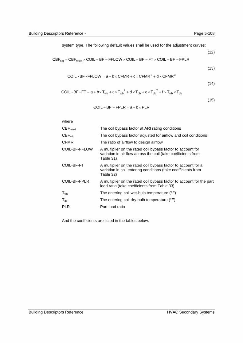
Building Descriptors Reference - Page 5-108
Building Descriptors Reference HVAC Secondary Systems
system type. The following default values shall be used for the adjustment curves:
(12)
FPLRBFCOILFTBFCOILFFLOWBFCOILCBFCBF ratedadj
(13)
32FFLOW-BF-COIL CFMRdCFMRcCFMRba
(14)
dbwbdbdbwbwb TTfTeTdTcTba 22
FT-BF-COIL
(15)
PLRbaFPLRBFCOIL
where
CBFrated The coil bypass factor at ARI rating conditions
CBFadj The coil bypass factor adjusted for airflow and coil conditions
CFMR The ratio of airflow to design airflow
COIL-BF-FFLOW A multiplier on the rated coil bypass factor to account forvariation in air flow across the coil (take coefficients fromTable 31)
COIL-BF-FT A multiplier on the rated coil bypass factor to account for avariation in coil entering conditions (take coefficients fromTable 32)
COIL-BF-FPLR A multiplier on the rated coil bypass factor to account for the partload ratio (take coefficients from Table 33)
Twb The entering coil wet-bulb temperature (°F)
Tdb The entering coil dry-bulb temperature (°F)
PLR Part load ratio
And the coefficients are listed in the tables below.

Building Descriptors Reference - Page 5-109
Building Descriptors Reference HVAC Secondary Systems
Table 31 – Coil Bypass Factor Airflow Adjustment FactorCoefficient COIL-BF-FFLOW (PTAC) COIL-BF-FFLOW (HP) COIL-BF-FFLOW (PSZ/other)
a -2.277 -0.8281602 -0.2542341
b 5.21140 14.3179150 1.2182558
c -1.93440 -21.8894405 0.0359784
d 9.3996897
Table 32 – Coil Bypass Factor Temperature Adjustment FactorCoefficient COIL-BF-FT (PTAC) COIL-BF-FT (HP) COIL-BF-FT (PSZ, other)
a -1.5713691 -29.9391098 1.0660053
b 0.0469633 0.8753455 -0.0005170
c 0.0003125 -0.0057055 0.0000567
d -0.0065347 0.1614450 -0.0129181
e 0.0001105 0.0002907 -0.0000017
f -0.0003719 -0.0031523 0.0001503
Table 33 – Coil Bypass Factor Part Load Adjustment FactorCoefficient COIL-BF-FPLR (All Systems)
a 0.00
b 1.00
Use defaults as described above.
5.7.5.2 Direct Expansion
Direct Expansion Cooling Efficiency
Packaged DX equipment
The cooling efficiency of a direct expansion (DX) cooling system at ARI ratedconditions as a ratio of output over input in Btu/h per W, excluding fan energy. Theabbreviation used for this full-load efficiency is EER.
For all unitary and applied equipment where the fan energy is part of the equipmentefficiency rating, the EER shall be adjusted as follows:
(16)
7457.0
545.2
,
,
supplyratedt
supplyratedtadj
BHPEER
Q
BHPQEER
where
EERadj The adjusted Energy Efficiency Ratio for simulation purposes
EER The rated Energy Efficiency Ratio
Qt,rated The ARI rated total cooling capacity of a packaged unit (kBtu/h)
BHPsupply The supply fan brake horsepower (bhp) shall be taken frommanufacturers’ literature when available, otherwise use Equation(5).
Standard Design
Applicability
Definition

Building Descriptors Reference - Page 5-110
Building Descriptors Reference HVAC Secondary Systems
Btu/h-W
As designed. When possible, specify the SEER and EER for packaged equipment withcooling capacity less than 65,000 Btu/h from manufacturer’s literature. For equipmentwith capacity above 65,000 Btu/h, specify EER.
When EER is not available for packaged equipment with SEER ratings (ARI coolingcapacity of 65,000 Btu/h or smaller), it shall be calculated as follows:
(17)
EER = 10 – (11.5 – SEER) x 0.83 when SEER<=11.5
= 10 when SEER>=11.5
Evaporative cooling systems that pass the requirements of the Western CoolingChallenge may be modeled with an EER as if the equipment were packaged unitaryequipment. The EER used is provided from the testing results, and may exceed 30 forsome systems.
Use the minimum cooling efficiency (EER) from tables in Tables 110.2-A, 110.2-B and110.2-E in Section 110.2 of the Standard.
Seasonal Energy Efficiency Ratio
Packaged DX equipment with ARI cooling capacity of 65,000 Btu/h or smaller
The seasonal cooling efficiency of a direct expansion (DX) cooling system at ARI ratedconditions as a ratio of output over input in Btu/h per W, excluding fan energy. Thesoftware must accommodate user input in terms of either the Energy Efficiency Ratio(EER) or the Seasonal Energy Efficiency Ratio (SEER). For equipment with SEERratings, EER shall be taken from manufacturers’ data when it is available.
Btu/h-W
As designed. This input is required for small DX systems. The Direct ExpansionCooling Efficiency input is optional for these systems.
Use the minimum SEER from the 2009 Appliance Efficiency Standards.
Direct Expansion Cooling Efficiency Temperature Adjustment Curve
Packaged DX equipment
A curve that varies the cooling efficiency of a direct expansion (DX) coil as a functionof evaporator conditions, condenser conditions, and for small packaged equipment,part-load ratio.
(18)
For air-cooled DX systems:
odbwbodbodbwbwb ttftetdtctbaFTEIR 22
_
(19)
For water-cooled DX systems:
wtwbwtwtwbwb ttftetdtctbaFTEIR 22
_
Units
Input Restrictions
Standard Design
Applicability
Definition
Units
Input Restrictions
Standard Design
Applicability
Definition

Building Descriptors Reference - Page 5-111
Building Descriptors Reference HVAC Secondary Systems
(20)
FTCAPFTEIRFPLREIRPP ratedoperating ___
where
PLR Part load ratio based on available capacity (not rated capacity)
EIR-FT A multiplier on the EIR to account for the wet-bulb temperatureentering the coil and the outdoor dry-bulb temperature
Qoperating Present load on heat pump (Btu/h)
Qavailable Heat pump available capacity at present evaporator andcondenser conditions (in Btu/h).
twb The entering coil wet-bulb temperature (°F)
twt The water supply temperature (°F)
todb The outside-air dry-bulb temperature (°F)
Prated Rated power draw at ARI conditions (kW)
Poperating Power draw at specified operating conditions (kW)
Note: if an air-cooled unit employs an evaporative condenser, todb is the effective dry-bulb temperature of the air leaving the evaporative cooling unit.
Table 34 – Cooling System Coefficients for EIR-FTCoefficient Water-Source
(Heat Pump)Water-Source(Other)
Air-Source (PTAC) Air-Source (PSZwith Cool Cap<=65,000 Btu/h)
Air-Source (Other)
a 2.0280385 -1.8394760 -0.6550461 n/a (see StandardDesign)
-1.0639310
b -0.0423091 0.0751363 0.0388910 n/a 0.0306584
c 0.0003054 -0.0005686 -0.0001925 n/a -0.0001269
d 0.0149672 0.0047090 0.0013046 n/a 0.0154213
e 0.0000244 0.0000901 0.0001352 n/a 0.0000497
f -0.0001640 -0.0001218 -0.0002247 n/a -0.0002096
Data structure
For equipment larger than 135,000 Btu/h, the user may enter data on equipmentperformance as described below. In this case, the ACM compliance software shall usethe algorithms described below to determine the temperature dependent performancecurves for the proposed design equipment. If the user chooses not to enter data ontemperature dependent performance, then the defaults shall be used.
For equipment with a capacity less than or equal to 135,000 Btu/h, but larger than65,000 Btu/h, the user may not enter data on the temperature dependent equipmentperformance. However, the ACM compliance software vendor may work withmanufacturers to collect such data and build this data into the ACM compliancesoftware. The user may either select equipment for which the ACM compliancesoftware vendor has collected or use the defaults.
NOTE: SECTION 2.5.2.6 OF THE NACM HAS SPECIFIC PROCEDURES FOR ENTERING IN USER
DATA (FOR INSTANCE, THE NORMALIZED EIR MUST BE MODIFIED BY A FFDD AND FAIR
ADJUSTMENT FACTORS BASED ON THE PRESENCE OF FDD AND AIRFLOW TESTING.)
Units
Input Restrictions

Building Descriptors Reference - Page 5-112
Building Descriptors Reference HVAC Secondary Systems
For all systems except packaged DX units with cooling capacity <= 65,000 Btu/h, usedefault curves from Table 55. For packaged DX units with cooling capacity less thanor equal to 65,000 Btu/h that have SEER ratings, the user inputs EER and SEER, andthe software generates the equipment performance curve based on the algorithmbelow.
NOTE: TITLE 24-2008 HAS A PROCEDURE FOR DEVELOPING A CURVE-FIT FOR THE EIR-FTBASED ON USER INPUTS OF SEER AND EER. THIS CURVE INCORPORATES BOTH
TEMPERATURE EFFECTS AND PART-LOAD EFFECTS. SOFTWARE MUST BE ABLE TO GENERATE
A BI-QUADRATIC CURVE FROM INPUT DATA TO USE THIS APPROACH. SEE 2.5.2.7 – THIS ONLY
APPLIES TO EQUIPMENT WITH SEER RATINGS.
This curve explains how the efficiency of the cooling equipment varies with the ODB and the EWB. Thiscurve is derived from entered or default values of SEER and EER, using the procedures below.
The curve is defined as a bi-quadratic with the following coefficients.
COOL-EIR- FT = CURVE-FITTYPE = BI-QUADRATICDATA = (67, 95, 1.0, $ARI Test Conditions
57, 82, NEIR57,82
57, 95, NEIR57,95,57,110,NEIR57,110,67, 82, NEIR67, 82,67,110, NEIR67,110,77, 82, NEIR77, 82,77, 95, NEIR77,95,77,110, NEIR77, 110)
OUTPUT-MIN = NEIR67, 82
NEIRWBT,ODB represents the normalized energy input ratio (EIR) for various entering wet-bulb (EWB) andoutside dry-bulb (ODB) temperatures. The value represents the EIR at the specified EWB and ODBconditions to the EIR at standard ARI conditions of 67° ºF wet-bulb and 95° ºF dry-bulb. The COOL-EIR-FT curve is normalized at ARI conditions of 67° ºF entering wet-bulb and 95° ºF outside dry-bulb soNEIR67,95 is one or unity, by definition. For other EWB and ODB conditions, values of NEIR are calculatedwith Equation N2-21.
Equation N2-2195,67
ODB,EWBODB,EWB
EIR
EIRNEIR
The energy input ratio (EIR) is the unitless ratio of energy input to cooling capacity. EIR includes thecompressor and condenser fan, but not the supply fan. If the energy efficiency ratio EERnf (EERexcluding the fan energy) is known for a given set of EWB and ODB conditions, the EIR for these sameconditions is given by Equation N2-22 below. The units of EER are (Btu/h)/W.
Equation N2-22ODB,EWB
ODB,EWBEERnf
413.3EIR
If the EER (including fan energy) is known for a given set of EWB and ODB conditions, then the EERnf(no fan) can be calculated from Equation N2-23 below.
Equation N2-23
AIRFDDODBEWB
ODBEWB
ODBEWBODBEWB
FFEER
EER
EEREERnf
3
,
2
,
,,
000251.0
0115.0
0452.1
Standard Design

Building Descriptors Reference - Page 5-113
Building Descriptors Reference HVAC Secondary Systems
Equation N2-24
AIRFDD3
ODB,EWB
2ODB,EWB
ODB,EWBODB,EWB
FF)EER000251.0
EER0115.0
EER0452.1(EERnf
The EER for different EWB and ODB conditions. These are given by the following equations.
Equation N2-25 SEEREER 82,67
Equation N2-26
11.5]SEERfor[default10
11.5]SEERfor[default83.0)SEER5.11(10
available][whenDataersManufacturFromEER 95,67
Equation N2-27 8.1EEREER 95,67110,67
Equation N2-28 ODB,67ODB,57 EER877.0EER
Equation N2-29 ODB,67ODB,77 EER11.1EER
FTXV Refrigerant charge factor, default = 0.9. For systems with a verified TXV or verified refrigerantcharge, the factor shall be 0.96.
FAIR Airflow adjustment factor. Default cooling air flow shall be assumed in calculations for anysystem in which the air flow has not been tested, certified and verified. For ACM compliancesoftware energy calculations the Fair multiplier shall be set to 0.925 for systems with defaultcooling air flow. For systems with air flow verified, Fair shall be 1.00.
EERnf Energy Efficiency Ratio at ARI conditions without distribution fanconsumption, but adjusted for refrigerant charge and airflow.
Direct Expansion Part-Load Efficiency Adjustment Curve
Packaged systems with direct expansion (DX) cooling
A normalized performance adjustment curve to the rated efficiency (Energy InputRatio) that describes how the efficiency varies at part-load conditions. At a value of 1(full load), the normalized efficiency is 1 (same as part-load conditions).
The default curves are given as follows as adjustments to the energy input ratio (EIR)8:
8 The EIR is the ratio of energy used by the system to cooling capacity in the same units. It is the reciprocal of the coefficient ofperformance (COP). EnergyPlus uses a part-load factor correlation for PLF as a function of PLR. The EnergyPlus PLF isrelated to the DOE-2 EIR(PLR) by the following: EIR-FPLR = PLR / PLF.
Applicability
Definition

Building Descriptors Reference - Page 5-114
Building Descriptors Reference HVAC Secondary Systems
(30)
wtodbwbavailable
operating
ttQ
QPLR
/,
(31)
32_ PLRdPLRcPLRbaFPLREIR
32_ PLRdPLRcPLRbaFPLRPLF
This curve may take the form of a part-load factor (PLF) or EIR-FLPR, which is thefraction of time the unit must run to meet the part-load for that hour. For example, at40% of full load, the equipment might need to run 50% of the hour (for cycling losses).
Note that for small packaged equipment with SEER ratings (<65,000 Btu/h), the part-load efficiency curve is set to no degradation, since the part-load degradation is built-into the Direct Expansion Cooling Efficiency Temperature Adjustment Curve.
Default curves are provided for the different major classes of equipment.
Coefficients (three for a quadratic, or up to four for a cubic)
The coefficients should sum to 1 (within a small tolerance). This corresponds to acurve output of 1 for an input of 1.
The baseline part-load efficiency adjustment curves are shown in the tables below.
Table 35 – Cooling System Coefficients for EIR-FPLRCoefficient Water-Source
(Heat Pump)Water-Source(Other)
Air-Source (PTAC) Air-Source (PSZwith Cap<65,000Btu/h)
Air-Source (Other)
a 0.1250000 0.2012301 0.1250000 0 0.2012301
b 0.8750000 -0.0312175 0.8750000 1 -0.0312175
c 0.0000000 1.9504979 0.0000000 0 1.9504979
d 0.0000000 -1.1205105 0.0000000 0 -1.1205105
Table 36 – Cooling System Coefficients for Part-Load Factor (PLF) Correlation (EnergyPlus)Coefficient Water-Source
(Heat Pump)Water-Source(Other)
Air-Source (PTAC) Air-Source (PSZwith Cap<65,000Btu/h)
Air-Source (Other)
a 0.85 0 0.85 1 0
b 0.15 5.1091 0.15 0 5.1091
c 0 -8.5515 0 0 -8.5515
d 0 4.4744 0 0 4.4744
Refrigerant Charge Factor
Packaged systems
An adjustment factor to the cooling efficiency and for heat pumps, heating efficiency,curves for packaged equipment. The refrigerant charge factor is a divisor in the term
Units
Input Restrictions
Standard Design
Applicability
Definition

Building Descriptors Reference - Page 5-115
Building Descriptors Reference HVAC Secondary Systems
for cooling efficiency (energy input ratio) or multiplier in the adjustment of energyefficiency ratio that assumes slightly degraded performance if refrigerant charge is notverified through acceptance test procedures in the Nonresidential Appendix of theStandards.
Ratio
Refrigerant charge factor, default = 0.9. For systems with a verified TXV or verifiedrefrigerant charge, the factor shall be 0.96. For evaporative cooling systems that meetthe Western Cooling Challenge requirements, the refrigerant charge factor shall be0.96.
The default shall be 0.96 for all systems with ARI cooling capacity of 54,000 Btu/h orgreater.
Airflow Adjustment Factor
Packaged systems
An adjustment factor to the cooling efficiency and for heat pumps, heating efficiency,curves for packaged equipment. The airflow adjustment factor is a divisor in the termfor cooling efficiency (energy input ratio) or multiplier in the term for energy efficiencyratio that assumes slightly degraded performance if airflow is not verified throughacceptance test procedures in the Nonresidential Appendix of the Standards.
Ratio
For ACM compliance software energy calculations the airflow adjustment factor (Fair)multiplier shall be set to 0.925 for systems with default cooling air flow. For systemswith air flow verified meeting the requirements of Reference Appendix NA9, Fair shallbe 1.00.
For evaporative cooling systems that meet the Western Cooling Challengerequirements, the airflow adjustment factor shall be 1.00.
The default shall be 1.00 for all systems with ARI cooling capacity of 54,000 Btu/h orgreater.
NOTE: THE FOLLOWING BUILDING DESCRIPTORS APPLY TO THE SINGLE-ZONE VAV SYSTEM, WHICH IS THE
BASELINE FOR APPLICABLE BUILDINGS WITH ZONE COOLING LOADS OF 110,000 BTU/H OR GREATER, AND
THE REQUIREMENT SCOPE EXPANDS TO UNITS WITH CAPACITY OF 75,000 BTU/H OR GREATER IN 2014 AND
65,000 BTU/H OR GREATER IN 2016.
.
Units
Input Restrictions
Standard Design
Applicability
Definition
Units
Input Restrictions
Standard Design

Building Descriptors Reference - Page 5-116
Building Descriptors Reference HVAC Secondary Systems
Number of Cooling Stages
Single Zone VAV Systems and DX systems with multiple stages
This applies to the baseline HVAC system Single Zone VAV. This system is apackaged unit with multiple compressors and a two-speed or variable-speed fan.Systems with unequally sized compressors may have additional cooling stages.
None (Integer)
As Designed
The default shall be 2 for the Single Zone VAV baseline.
Total Cooling Capacity by Stage
Single Zone VAV Systems and DX systems with multiple stages
This provides the total cooling capacity of each cooling stage, at ARI rated conditions.The capacity is expressed as an array, with each entry a fraction of the total ratedcooling capacity for the unit. For example, if the stage cooling capacity is 4 tons(48,000 Btu/h) and the total cooling capacity is 8 tons (96,000 Btu/h), the capacity isexpressed as “0.50” for that stage.
Array of fractions
As Designed
The default shall be (0.50, 1) for the Single Zone VAV baseline.
Sensible Cooling Capacity by Stage
Single Zone VAV Systems and DX systems with multiple stages
This provides the sensible cooling capacity of each cooling stage, at ARI ratedconditions. The capacity is expressed as an array, with each entry a fraction of thetotal rated cooling capacity for the unit. For example, if the stage sensible coolingcapacity is 3 tons (36,000 Btu/h) and the total cooling capacity is 9 tons (108,000Btu/h), the capacity is expressed as “0.33” for that stage.
Array of fractions
As Designed
The default shall be (0.50, 1) for the Single Zone VAV baseline.
Supply Air Temperature Reset by Stage
Single Zone VAV Systems and DX systems with multiple stages
This provides the cooling supply air temperature setpoint deviation from the coolingdesign supply air temperature, specified in the building descriptor Cooling Supply AirTemperature.
The temperature reset is expressed as an array, with each entry a deviation from thedesign supply air temperature. For example, an entry of “5” for a stage would indicatea 5°F reset (for example, 60°F from 55°F).
Array of temperature differences, in degrees F
As Designed
The default shall be (5,0) for the Single Zone VAV baseline.
Applicability
Definition
Units
Input Restrictions
Standard Design
Applicability
Definition
Units
Input Restrictions
Standard Design
Applicability
Definition
Units
Input Restrictions
Standard Design
Applicability
Definition
Units
Input Restrictions
Standard Design

Building Descriptors Reference - Page 5-117
Building Descriptors Reference HVAC Secondary Systems
Number of Heating Stages
Single Zone VAV Systems and DX systems with multiple stages
The number of heating stages provided by the system. Multiple stages could beprovided via a heat pump or via a multiple-stage gas furnace.
Integer
As Designed
The default shall be 2 for the Single Zone VAV baseline.
Heating Capacity by Stage
Single Zone VAV Systems and DX systems with multiple stages
This provides the total heating capacity of each heating stage, at ARI rated conditions.The capacity is expressed as an array, with each entry a fraction of the total ratedcooling capacity for the unit. For example, if the stage heating capacity is 48,000Btu/h and the heating capacity is 96,000 Btu/h, the capacity is expressed as “0.50” forthat stage.
Array of fractions
As Designed
The default shall be (0.50, 1) for the Single Zone VAV baseline.
Heating Supply Air Temperature by Stage
Single Zone VAV Systems and DX systems with multiple stages
This provides the heating supply air temperature setpoint deviation from the designheating supply air temperature, specified in the building descriptor Cooling Supply AirTemperature.
The temperature reset is expressed as an array, with each entry a deviation from thedesign supply air temperature. For example, an entry of “10” for a stage wouldindicate a 10°F reset (for example, 95°F from 105°F).
Array of temperature differences, in degrees F
As Designed
The default shall be -10F for the first cooling stage and 0 for the second (high) coolingstage.
Supply Fan Low Speed Ratio
Single Zone VAV Systems and DX systems with multiple stages and two-speed fans
This specifies the low fan speed setting on a Single Zone VAV system or DX systemwith multiple cooling stages.
None (fraction)
As Designed
The default shall be 0.66 for the Single Zone VAV baseline.
Supply Fan Low Power Ratio
Applicability
Definition
Units
Input Restrictions
Standard Design
Applicability
Definition
Units
Input Restrictions
Standard Design
Applicability
Definition
Units
Input Restrictions
Standard Design
Applicability
Definition
Units
Input Restrictions
Standard Design
Applicability

Building Descriptors Reference - Page 5-118
Building Descriptors Reference HVAC Secondary Systems
Single Zone VAV Systems and DX systems with multiple stages and two-speed fans
This specifies the fraction of full load fan power corresponding to low fan speedoperation on a Single Zone VAV system or DX system with multiple cooling stages.
None (fraction)
As Designed
The default shall be 0.40 for the Single Zone VAV baseline.
NOTE: THE FOLLOWING FOUR BUILDING DESCRIPTORS REPLACE THE PROCEDURE FROM THE 2008NONRESIDENTIAL ACM APPENDIX D FOR DISTRIBUTION LOSSES FOR DUCTWORK IN UNCONDITIONED
SPACES.
Duct Leakage Rate
Packaged single-zone systems serving spaces less than 5,000 ft2 with ducts inunconditioned spaces
The duct air leakage rate from the supply and return duct of a packaged single zonesystem with ducts in unconditioned spaces.
Ratio
The input may contain one of the following three values:
Table 37 – Duct Leakage Factorsas = ar =
Untested duct systems 0.82
Sealed and tested duct systems in existing buildings,System tested after HVAC equipment and/or ductinstallation
0.915
Sealed and tested new duct systems.System tested after HVAC system installation
0.96
The baseline value shall be 0.96, except: for systems that serve residentialoccupancies including hotel/motel guest rooms, the baseline value shall be the sameas proposed.
Duct Surface Area
Packaged single-zone systems serving non-residential spaces less than 5,000 ft2 withducts in unconditioned spaces
The duct surface area used for duct heat transfer calculations.
ft2
Any positive number
For systems serving nonresidential occupancies, the default duct surface area shallbe:
The default duct surface area for supply and return shall be calculated as follows:
For supplies:
Definition
Units
Input Restrictions
Standard Design
Applicability
Definition
Units
Input Restrictions
Standard Design
Applicability
Definition
Units
Input Restrictions
Standard Design
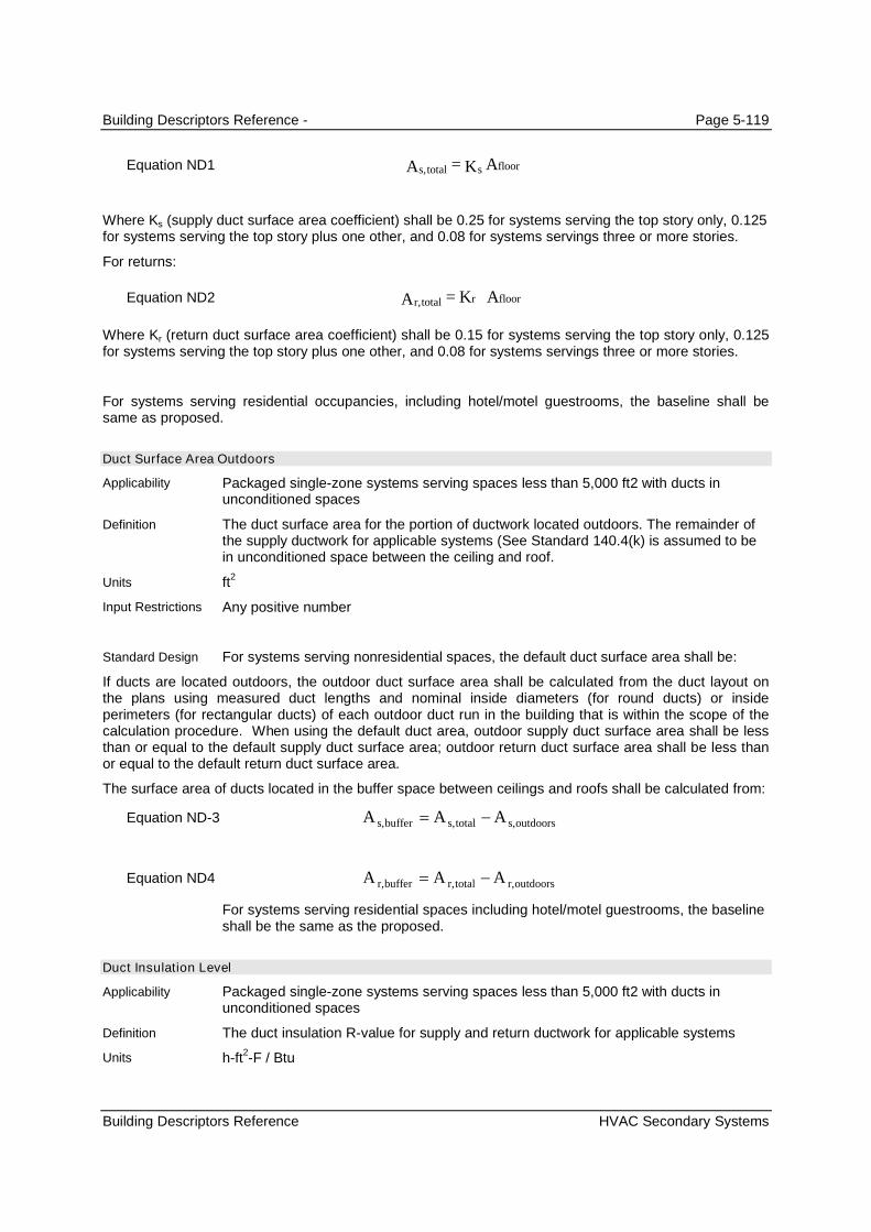
Building Descriptors Reference - Page 5-119
Building Descriptors Reference HVAC Secondary Systems
Equation ND1 floorstotals, AK=A
Where Ks (supply duct surface area coefficient) shall be 0.25 for systems serving the top story only, 0.125for systems serving the top story plus one other, and 0.08 for systems servings three or more stories.
For returns:
Equation ND2 AK=A floorrtotalr,
Where Kr (return duct surface area coefficient) shall be 0.15 for systems serving the top story only, 0.125for systems serving the top story plus one other, and 0.08 for systems servings three or more stories.
For systems serving residential occupancies, including hotel/motel guestrooms, the baseline shall besame as proposed.
Duct Surface Area Outdoors
Packaged single-zone systems serving spaces less than 5,000 ft2 with ducts inunconditioned spaces
The duct surface area for the portion of ductwork located outdoors. The remainder ofthe supply ductwork for applicable systems (See Standard 140.4(k) is assumed to bein unconditioned space between the ceiling and roof.
ft2
Any positive number
For systems serving nonresidential spaces, the default duct surface area shall be:
If ducts are located outdoors, the outdoor duct surface area shall be calculated from the duct layout onthe plans using measured duct lengths and nominal inside diameters (for round ducts) or insideperimeters (for rectangular ducts) of each outdoor duct run in the building that is within the scope of thecalculation procedure. When using the default duct area, outdoor supply duct surface area shall be lessthan or equal to the default supply duct surface area; outdoor return duct surface area shall be less thanor equal to the default return duct surface area.
The surface area of ducts located in the buffer space between ceilings and roofs shall be calculated from:
Equation ND-3 outdoorss,totals,buffers, AAA
Equation ND4 outdoorsr,totalr,bufferr, AAA
For systems serving residential spaces including hotel/motel guestrooms, the baselineshall be the same as the proposed.
Duct Insulation Level
Packaged single-zone systems serving spaces less than 5,000 ft2 with ducts inunconditioned spaces
The duct insulation R-value for supply and return ductwork for applicable systems
h-ft2-F / Btu
Applicability
Definition
Units
Input Restrictions
Standard Design
Applicability
Definition
Units

Building Descriptors Reference - Page 5-120
Building Descriptors Reference HVAC Secondary Systems
Any positive number
Nonresidential buildings: R-8 is the baseline insulation level for ductwork in both newconstruction and alterations of existing buildings
Residential Buildings (including hotel/motel guestrooms): same as proposed
Minimum Unloading Ratio
Packaged systems which use hot-gas bypass during low load conditions
The upper end of the hot-gas bypass operating range. This is the percentage of peakcooling capacity below which hot-gas bypass will operate.
The actual unloading ratio shall be set to 50% of the user-entered minimum unloadingratio, with hot-gas-bypass operating below this level.
Ratio
As designed. The user must enter this descriptor for each DX cooling system. If hot-gas bypass is not employed, a value of 0 may be entered. A maximum of 0.35 isallowed for units with a peak cooling capacity greater than or equal to 65 kBtu/h andless than 240 kBtu/h (20 tons), and a maximum value of 0.25 is allowed for units with apeak cooling capacity greater than 240 kBtu/h.
Not applicable
Minimum HGB Ratio
Packaged systems which use hot-gas bypass during low load conditions
The lower end of the hot-gas bypass operating range. The percentage of peak coolingcapacity below which hot-gas bypass will no longer operate (i.e. the compressor willcycle).
Ratio
0
0
Condenser Type
All direct expansion systems including heat pumps
The type of condenser for a direct expansion (DX) cooling system. The choices are:
Air-Cooled
Water-Cooled
Air-Cooled with Evaporative Pre-cooler
List (see above)
As designed
Based on the prescribed system type. Refer to the HVAC System Map in Error!Reference source not found..
Input Restrictions
Standard Design
Applicability
Definition
Units
Input Restrictions
Standard Design
Applicability
Definition
Units
Input Restrictions
Standard Design
Applicability:
Definition
Units
Input Restrictions
Standard Design

Building Descriptors Reference - Page 5-121
Building Descriptors Reference HVAC Secondary Systems
Table 38 – Baseline Building Condenser TypeBaseline building System Condenser Type
System 1 – PTAC Air-cooled
System 2 – FPFC Water-cooled
System 3 – PSZ-AC Air-cooled
System 5 – Packaged VAV with Reheat Air-cooled
System 6 – VAV with Reheat Water-Cooled
System 7 – Single Zone VAV N/A
System 9 – Heating and Ventilation N/A
System 10 – CRAH Unit Water-Cooled
System 11 – CRAC Unit N/A
Condenser Flow Type
All direct expansion systems including heat pumps
Describes water flow control for a water-cooled condenser. The choices are:
Fixed Flow
Two-position
Variable Flow
List (see above)
Default to fixed flow. If the variable-flow is selected, the software must indicate thatsupporting documentation is required on the output forms.
Always fixed flow
5.7.5.3 Evaporative Cooler
This is equipment that pre-cools the outside air that is brought into the building. It may be used with anytype of cooling system that brings in outside air. This equipment is not applicable for the baseline building.
Evaporative Cooling Type
Systems with evaporative pre-cooling
The type of evaporative pre-cooler, including:
None
Non-Integrated Indirect
Non-Integrated Direct/Indirect
Integrated Indirect
Integrated Direct/Indirect
Western Cooling Challenge (high efficiency)
An integrated pre-cooler can operate together with the compression or CHW cooling.A non-integrated pre-cooler will shut down the evaporative cooling whenever it isunable to provide 100% of the cooling required.
In all cases, the evaporative pre-cooler must be modeled with 100% of the outside airrouted through the pre-cooler.
Applicability:
Definition
Units
Input Restrictions
Standard Design
Applicability
Definition
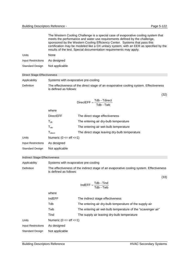
Building Descriptors Reference - Page 5-122
Building Descriptors Reference HVAC Secondary Systems
The Western Cooling Challenge is a special case of evaporative cooling system thatmeets the performance and water use requirements defined by the challenge,sponsored by the Western Cooling Efficiency Center. Systems that pass thiscertification may be modeled like a DX unitary system, with an EER as specified by theresults of the test. Special documentation requirements may apply.
None
As designed
Not applicable
Direct Stage Effectiveness
Systems with evaporative pre-cooling
The effectiveness of the direct stage of an evaporative cooling system. Effectivenessis defined as follows:
(32)
TwbTdb
TdirectTdbDirectEFF
where
DirectEFF The direct stage effectiveness
Tdb The entering air dry-bulb temperature
Twb The entering air wet-bulb temperature
Tdirect The direct stage leaving dry-bulb temperature
Numeric (0 <= eff <=1)
As designed
Not applicable
Indirect Stage Effectiveness
Systems with evaporative pre-cooling
The effectiveness of the indirect stage of an evaporative cooling system. Effectivenessis defined as follows:
(33)
TwbTdb
TindTdbIndEFF
where
IndEFF The indirect stage effectiveness
Tdb The entering air dry-bulb temperature of the supply air
Twb The entering air wet-bulb temperature of the “scavenger air”
Tind The supply air leaving dry-bulb temperature
Numeric (0 <= eff <=1)
As designed
Not applicable
Units
Input Restrictions
Standard Design
Applicability
Definition
Units
Input Restrictions
Standard Design
Applicability
Definition
Units
Input Restrictions
Standard Design

Building Descriptors Reference - Page 5-123
Building Descriptors Reference HVAC Secondary Systems
Evaporative Cooling Performance Curves
Systems with evaporative cooling
A curve that varies the evaporative cooling effectiveness as a function of primary airstream airflow. The default curves are given as follows:
(34)
2_ PLRcPLRbaFFLOWEFF
CFM
CFMPLR
design
operating
where
PLR Part load ratio of airflow based on design airflow
EFF-FFLOW A multiplier on the evaporative cooler effectiveness to accountfor variations in part load
CFMoperating Operating primary air stream airflow (cfm)
CFMdesign Design primary air stream airflow (cfm)
Table 39 – Part Load Curve Coefficients – Evaporative Cooler EffectivenessCoefficient Direct Indirect
a 1.1833000 1.0970000
b -0.2575300 -0.1650600
c 0.0742450 0.0680690
Data structure
User may input curves or use default curves. If defaults are overridden, the softwaremust indicate that supporting documentation is required on the output forms.
Not used.
Auxiliary Evaporative Cooling Power
Systems with evaporative cooling
The auxiliary energy of the indirect evaporative cooler fan, and the pumps for bothdirect and indirect stages
- Watts
As designed
Not applicable
Evaporative Cooling Scavenger Air Source
Systems with evaporative cooling
The source of scavenger air for an indirect section of an evaporative cooler. Optionsinclude:
Return Air
Outside Air
Applicability
Definition
Units
Input Restrictions
Standard Design
Applicability
Definition
Units
Input Restrictions
Standard Design
Applicability
Definition

Building Descriptors Reference - Page 5-124
Building Descriptors Reference HVAC Secondary Systems
List (see above)
As designed
Not applicable
5.7.5.4 Evaporative Condenser
Evaporative Condenser Power
Direct expansion systems with an evaporatively cooled condenser
The power of the evaporative precooling unit. This includes any pump(s) and/or fansthat are part of the precooling unit.
Watts
As designed
Not applicable
Evaporative Condenser Effectiveness
Direct expansion systems with an evaporatively cooled condenser
The effectiveness of the evaporative precooling unit for a condenser. Effectiveness isdefined as follows:
(35)
TwbTdb
TdirectTdbDirectEFF
where
DirectEFF The direct stage effectiveness
Tdb The outside air dry-bulb temperature
Twb The outside air wet-bulb temperature
Tdirect The direct stage leaving dry-bulb temperature (at the condenserinlet)
Ratio
As designed
Not applicable
Evaporative Condenser Operation Range
Direct expansion systems with an evaporatively cooled condenser.
The temperature range within which the evaporative condenser operates. Two valuesare provided:
Tmaximum The threshold outside air dry-bulb temperature below whichevaporative condenser operates.
Tminimum The threshold outside air dry-bulb temperature above whichevaporative condenser operates.
Degrees Fahrenheit (°F)
Units
Input Restrictions
Standard Design
Applicability
Definition
Units
Input Restrictions
Standard Design
Applicability
Definition
Units
Input Restrictions
Standard Design
Applicability
Definition
Units
Input Restrictions

Building Descriptors Reference - Page 5-125
Building Descriptors Reference HVAC Secondary Systems
As designed
Not applicable
5.7.5.5 Radiant Cooling
This section describes a floor-based radiant cooling system and the inputs required for Title 24compliance evaluation.
Hydronic Tubing Length
Floor-based radiant cooling systems
The length of the hydronic tubing in the slab
ft
As designed
Not applicable
Hydronic Tubing Inside Diameter
Floor-based radiant cooling systems
The inside diameter of the hydronic tubing in the slab
ft
As designed, between a minimum of ½” and a maximum of ¾”
Not applicable
Temperature Control Type
Floor-based radiant cooling systems
The temperature used for control (operative temperature, mean air temperature, meanradiant temperature, ODB, OWB
None
Fixed at Mean Air Temperature for compliance calculations
Not applicable
Rated Flow Rate
Floor-based radiant cooling systems
The temperature used for control (operative temperature, mean air temperature, meanradiant temperature, ODB, OWB
None
Fixed at Mean Air Temperature for compliance calculations
Not applicable
Cooling Control Temperature
Variable Flow Systems
The temperature used for control (operative temperature, mean air temperature, mean
Standard Design
Applicability
Definition
Units
Input Restrictions
Standard Design
Applicability
Definition
Units
Input Restrictions
Standard Design
Applicability
Definition
Units
Input Restrictions
Standard Design
Applicability
Definition
Units
Input Restrictions
Standard Design
Applicability
Definition

Building Descriptors Reference - Page 5-126
Building Descriptors Reference HVAC Secondary Systems
radiant temperature, ODB, OWB
None
Fixed at Mean Air Temperature for compliance calculations
Not applicable
Condensation Control Type
Floor-based radiant cooling systems
The temperature used for control (operative temperature, mean air temperature, meanradiant temperature, ODB, OWB
None
Fixed at Mean Air Temperature for compliance calculations
Not applicable
Condensation Control Dewpoint Offset
Floor-based radiant cooling systems
The temperature difference above dewpoint that is the minimum cold water supplytemperature
None
Fixed at 2°F above dewpoint
Not applicable
Rated Pump Power Consumption
Floor-based radiant cooling systems
The rated pump power at design conditions
Watts
As Designed
Not applicable
Motor Efficiency
Floor-based radiant cooling systems
The pump motor efficiency
Decimal fraction
As Designed
Default motor efficiency from Table N2-20 (Table numbering may change) based onmotor nameplate hp
Fraction of Motor Heat to Fluid
Floor-based radiant cooling systems
Fraction of the heat from the motor inefficiencies that enters the fluid stream
Units
Input Restrictions
Standard Design
Applicability
Definition
Units
Input Restrictions
Standard Design
Applicability
Definition
Units
Input Restrictions
Standard Design
Applicability
Definition
Units
Input Restrictions
Standard Design
Applicability
Definition
Units
Input Restrictions
Standard Design
Applicability
Definition

Building Descriptors Reference - Page 5-127
Building Descriptors Reference HVAC Secondary Systems
none
As designed. Default is 0.
Not applicable
Cooling High Water Temperature
Floor-based radiant cooling systems
The high temperature used for control. If the water temperature is above the hightemperature, the control temperature is set to the low control temperature.
Deg F
As Designed
Not applicable
Cooling Low Water Temperature
Floor-based radiant cooling systems
The temperature used for control of the water temperature. If the water temperature ofthe radiant cooling is below this temperature, cooling is disabled.
Deg F
Fixed at 55°F
Not applicable
Condensation Control Type
Floor-based radiant cooling systems
The simulation program may have a means of detecting when condensation is likely tooccur on floor surfaces in the space. When this occurs, the simulation can shut off thesystem to prevent condensation from occurring.
List: None, Simple, Variable
As designed
Not applicable
5.7.5.6 Chilled Beams
Reserved. Building descriptors will be added to define how chilled beams can be modeled for theproposed design. Chilled beams are not applicable to the standard design system.
5.7.5.7 Ground-Source Heat Pumps
Reserved. Building descriptors will be added to define how ground-source heat pumps can be modeledfor the proposed design. Chilled beams are not applicable to the standard design system.
5.7.5.8 Variable Refrigerant Flow
Reserved. Building descriptors will be added to define how VRF systems can be modeled for theproposed design. Chilled beams are not applicable to the standard design system.
Units
Input Restrictions
Standard Design
Applicability
Definition
Units
Input Restrictions
Standard Design
Applicability
Definition
Units
Input Restrictions
Standard Design
Applicability
Definition
Units
Input Restrictions
Standard Design

Building Descriptors Reference - Page 5-128
Building Descriptors Reference HVAC Secondary Systems
5.7.5.9 Underfloor Air Distribution
Reserved. Building descriptors will be added to define how UFAD systems can be modeled for theproposed design. Chilled beams are not applicable to the standard design system.
5.7.6 Heating Systems
5.7.6.1 General
Heating Source
All systems that provide heating
The source of heating for the heating and preheat coils. The choices are:
Hot water
Steam
Electric resistance
Electric heat pump
Gas furnace
Gas heat pump (optional feature)
Oil furnace
Heat recovery (for preheat coils in proposed designs)
List (see above)
As designed
Based on the prescribed system type. Refer to the HVAC System Map in Table5Error! Reference source not found..
Table 40 – Heating Source for Baseline BuildingBaseline Building System Heating Source
System 1 – PTAC Gas Furnace
System 2 – FPFC Hot water
System 3 – PSZ-AC Gas or Oil Furnace
System 5 – Packaged VAV with Reheat Hot water
System 6 – VAV with Reheat Hot water
System 7 – Single Zone VAV Gas or Oil Furnace
System 9 – Heating and Ventilation Gas or Oil Furnace
System 10 – CRAH Unit, Data Center None
System 11 – CRAC Unit, Data Center None
5.7.6.2 Preheat Coil
If the proposed design has a preheat coil and it can be modeled in the baseline building system, then thebaseline building also has a preheat coil sized to meet the preheat coil temperature specified for theproposed design.
Applicability
Definition
Units
Input Restrictions
Standard Design

Building Descriptors Reference - Page 5-129
Building Descriptors Reference HVAC Secondary Systems
Preheat Coil Capacity
Systems with a preheat coil located in the outside air stream
The heating capacity of a preheating coil at design conditions.
Btu/h
As designed
The baseline building has a pre-heat coil when the proposed design has one. Autosizeto maintain the preheat coil temperature of the proposed design.
Preheat Coil Efficiency
Systems with a preheat coil with gas heating
The heating efficiency of a preheating coil at design conditions.
Percentage
As designed. Default is 80%.
The baseline building has a pre-heat coil when the proposed design has one. Autosizeto maintain the preheat coil temperature of the proposed design.
5.7.6.3 Hydronic/Steam Heating Coils
Systems with boilers have heating coils, including baseline building systems 1, 5 and 6 and 10.
Heating Coil Capacity
All systems with a heating coil
The heating capacity of a heating coil at ARI conditions
Btu/h
As designed. Adjust the capacity if the number of unmet load hours exceeds 300.
Autosize with a heating oversizing factor of 25%. If the number of unmet load hours forthe baseline exceeds, reduce the heating coil capacity as indicated in Section 2.6.2.
5.7.6.4 Furnace
Furnace Capacity
Systems with a furnace
The full load heating capacity of the unit
Btu/h
As designed. Adjust the capacity if the number of unmet load hours exceeds 300.
Autosize with an oversizing factor of 25% (let the software determine heating capacitybased on the building loads). If the number of unmet load hours for the baseline exceeds 300, reduce thefurnace capacity as indicated in Figure 2 and 2.6.2
Furnace Fuel Heating Efficiency
Applicability
Definition
Units
Input Restrictions
Standard Design
Applicability
Definition
Units
Input Restrictions
Standard Design
Applicability
Definition
Units
Input Restrictions
Standard Design
Applicability
Definition
Units
Input Restrictions
Standard Design
Applicability

Building Descriptors Reference - Page 5-130
Building Descriptors Reference HVAC Secondary Systems
Systems with a furnace
The full load thermal efficiency of either a gas or oil furnace at design conditions. Thesoftware must accommodate input in either Thermal Efficiency (Et) or Annual FuelUtilization Efficiency (AFUE). Where AFUE is provided, Et shall be calculated asfollows:
(36)
098185.0011116.0
83.5AFUESystems,Split)3
5787.0002907.0
83.5AFUESystems,Split)2
4033.0005163.0
EquipmentPackageSingleAll1)
AFUEE
AFUEE
AFUEE
t
t
t
where
AFUE The annual fuel utilization efficiency (%)
Et The thermal efficiency (fraction)
Fraction
As designed
The baseline efficiency requirement is located in Table E-3 of the 2009 ApplianceEfficiency Standards. Use the heating input of the proposed design system todetermine the size category.
Furnace Fuel Heating Part Load Efficiency Curve
Systems with furnaces
An adjustment factor that represents the percentage of full load fuel consumption as afunction of the percentage full load capacity. This curve shall take the form of aquadratic equation as follows:
(37)
FHeatPLCFuelFuel ratedpartload
(38)
2
rated
partload
rated
partload
Q
Qc
Q
QbaFHeatPLC
where
FHeatPLC The Fuel Heating Part Load Efficiency Curve
Fuelpartload The fuel consumption at part load conditions (Btu/h)
Fuelrated The fuel consumption at full load (Btu/h)
Qpartload The capacity at part load conditions (Btu/h)
Qrated The capacity at rated conditions (Btu/h)
Definition
Units
Input Restrictions
Standard Design
Applicability
Definition

Building Descriptors Reference - Page 5-131
Building Descriptors Reference HVAC Secondary Systems
Table 41 – Furnace Efficiency Curve CoefficientsCoefficient Furnace
a 0.0186100
b 1.0942090
c -0.1128190
Data structure
Fixed
Fixed
Furnace Fuel Heating Pilot
Systems that use a furnace for heating
The fuel input for a pilot light on a furnace
Btu/h
As designed
Zero (pilotless ignition)
Furnace Fuel Heating Fan/Auxiliary
Systems that use a furnace for heating
The fan energy in forced draft furnaces and the auxiliary (pumps and outdoor fan)energy in fuel-fired heat pumps
Kilowatts (kW)
As designed
Not applicable
5.7.6.5 Electric Heat Pump
Electric Heat Pump Heating Capacity
All heat pumps
The full load heating capacity of the unit, excluding supplemental heating capacity atARI rated conditions
Btu/h
As designed
Autosize and use an oversizing factor of 25% (let the software determine heatingcapacity based on the building loads). The autosized equipment may need to bedownsized to ensure that the number of unmet load hours do not exceed 300.
Electric Heat Pump Supplemental Heating Source
All heat pumps
The auxiliary heating source for a heat pump heating system. The common controlsequence is to lock out the heat pump compressor when the supplemental heat is
Units
Input Restrictions
Standard Design
Applicability
Definition
Units
Input Restrictions
Standard Design
Applicability
Definition
Units
Input Restrictions
Standard Design
Applicability
Definition
Units
Input Restrictions
Standard Design
Applicability
Definition

Building Descriptors Reference - Page 5-132
Building Descriptors Reference HVAC Secondary Systems
activated. Other building descriptors may be needed if this is not the case. Choices forsupplemental heat include:
Electric resistance
Gas furnace
Oil furnace
Hot water
Other
List (see above)
As designed
Electric resistance
Electric Heat Pump Heating Efficiency
All heat pumps
The heating efficiency of a heat pump at ARI rated conditions as a dimensionless ratioof output over input. The software must accommodate user input in terms of either theCoefficient of Performance (COP) or the Heating Season Performance Factor (HSPF).Where HSPF is provided, COP shall be calculated as follows:
(39)
2606.04813.0
SystemsSplitAll2)
9667.02778.0
EquipmentPackageSingleAll1)
HSPFCOP
HSPFCOP
For all unitary and applied equipment where the fan energy is part of the equipmentefficiency rating, the COP shall be adjusted as follows to remove the fan energy:
(40)
7457.0413.3
7457.0413.3
supplyrated
supplyrated
adj
BHPCOP
HCAP
BHPHCAP
COP
where
COPadj The adjusted coefficient of performance for simulation purposes
COP The ARI rated coefficient of performance
HCAPrated The ARI rated heating capacity of a packaged unit (kBtu/h)
BHPsupply The supply fan brake horsepower (bhp).
Refer to building descriptor Supply Fan BHP.
Unitless
As designed
Units
Input Restrictions
Standard Design
Applicability
Definition
Units
Input Restrictions
Standard Design

Building Descriptors Reference - Page 5-133
Building Descriptors Reference HVAC Secondary Systems
The minimum requirement is defined in Table 110.2-B of the Standards. Use theheating capacity of the proposed design to determine the size category.
Electric Heat Pump Heating Capacity Adjustment Curve(s)
All heat pumps
A curve or group of curves that represent the available heat-pump heating capacity asa function of evaporator and condenser conditions. The default curves are given asfollows:
(41)
ratedavailable QFTCAPQ _
(42)
For air-cooled heat pumps:
32_ odbodbodb tdtctbaFTCAP
(43)
For water-cooled heat pumps:
wtdb tdtbaFTCAP _
where
Qavailable Available heating capacity at present evaporator and condenserconditions (kBtu/h)
tdb The entering coil dry-bulb temperature (°F)
twt The water supply temperature (°F)
todb The outside-air dry-bulb temperature (°F)
Qrated Rated capacity at ARI conditions (in kBtu/h)
Table 42 – Heat Pump Capacity Adjustment Curves (CAP-FT)Coefficient Water-Source Air-Source
a 0.4886534 0.2536714
b -0.0067774 0.0104351
c N/A 0.0001861
d 0.0140823 -0.0000015
Data structure
User may input curves or use default curves. If defaults are overridden, supportingdocumentation shall be provided.
(SEE 2.5.2.7 OF THE 2008 NACM)
For air-cooled heat pumps, the user may enter the heating capacity at two differentoutdoor dry-bulb temperatures: 17°F and 47°F. The compliance software shall be ableto generate a curve-fit of the following data points for normalized capacity as a functionof outside air dry-bulb temperature:
DATA = (67,1.337)= (57,1.175)= (47,1.000)= (17,CAP17/CAP47)
Applicability
Definition
Units
Input Restrictions

Building Descriptors Reference - Page 5-134
Building Descriptors Reference HVAC Secondary Systems
= (7,0.702CAP17/CAP47)= (-13, 0.153)
Use default curves.
Electric Heat Pump Heating Efficiency Adjustment Curve(s)
All heat pumps
A curve or group of curves that varies the heat-pump heating efficiency as a functionof evaporator conditions, condenser conditions and part-load ratio. The default curvesare given as follows:
(44)
wtodbdbavailable
operating
ttQ
QPLR
/,
(45)
32_ PLRdPLRcPLRbaFPLREIR
Air Source Heat Pumps:
(46)
32
_
db
odb
db
odb
db
odb
t
td
t
tc
t
tbaFTEIR
Water Source Heat Pumps:
(47)
dbwt tdtbaFTEIR _
(48)
FTCAPFTEIRFPLREIRPP ratedoperating ___
where
PLR Part load ratio based on available capacity (not rated capacity)
EIR-FPLR A multiplier on the EIR of the heat pump as a function of partload ratio
EIR-FT A multiplier on the EIR of the heat pump as a function of the wet-bulb temperature entering the coil and the outdoor dry-bulbtemperature
Qoperating Present load on heat pump (Btu/h)
Qavailable Heat pump available capacity at present evaporator andcondenser conditions (Btu/h) .
tdb The entering coil dry-bulb temperature (°F)
twt The water supply temperature (°F)
todb The outside air dry-bulb temperature (°F)
Prated Rated power draw at ARI conditions (kW)
Poperating Power draw at specified operating conditions (kW)
Standard Design
Applicability
Definition

Building Descriptors Reference - Page 5-135
Building Descriptors Reference HVAC Secondary Systems
Table 43 – Heat Pump Heating Efficiency Adjustment CurvesCoefficient Air-and Water-Source
EIR-FPLRWater-SourceEIR-FT
Air-SourceEIR-FT
a 0.0856522 1.3876102 2.4600298
b 0.9388137 0.0060479 -0.0622539
c -0.1834361 N/A 0.0008800
d 0.1589702 -0.0115852 -0.0000046
None
User may input curves or use default curves. If defaults are overridden, documentationshall be provided.
The Compliance software shall be capable of generating a curve given user inputs ofCOP at 17°F and 47°F as follows:
DATA = (67,0.856)= (57,0.919)= (47,1.000)= (17,COP47/COP17)= (7,1.266COP47/COP17)= (-13, 3.428)
Use default curves
Electric Heat Pump Supplemental Heating Capacity
All heat pumps
The design heating capacity of a heat pump supplemental heating coil at ARIconditions
Btu/h
As designed
Autosize
Electric Supplemental Heating Control Temp
All heat pumps
The outside dry-bulb temperature below which the heat pump supplemental heating isallowed to operate
Degrees Fahrenheit (°F)
As designed. Default to 40°F
40°F
Heat Pump Compressor Minimum Operating Temp
All heat pumps
The outside dry-bulb temperature below which the heat pump compressor is disabled
Degrees Fahrenheit (°F)
As designed. Default to 17°F
17°F
Units
Input Restrictions
Standard Design
Applicability
Definition
Units
Input Restrictions
Standard Design
Applicability
Definition
Units
Input Restrictions
Standard Design
Applicability
Definition
Units
Input Restrictions
Standard Design

Building Descriptors Reference - Page 5-136
Building Descriptors Reference HVAC Secondary Systems
Coil Defrost
Air-cooled electric heat pump
The defrost control mechanism for an air-cooled heat pump. The choices are:
Hot-gas defrost, on-demand
Hot-gas defrost, timed 3.5 minute cycle
Electric resistance defrost, on-demand
Electric resistance defrost, timed 3.5 minute cycle
Defrost shall be enabled whenever the outside air dry-bulb temperature drops below40°F.
List (see above)
Default to use hot-gas defrost, timed 3.5 minute cycle. User may select any of theabove.
The baseline building uses the default. NOTE: THIS IS NOT DEFINED IN THE T24-2008NACM.
Coil Defrost kW
Heat pumps with electric resistance defrost
The capacity of the electric resistance defrost heater
Kilowatts (kW)
As designed. This descriptor defaults to 0 if nothing is entered.
Not applicable. Baseline building systems 2 and 4 use hot-gas, timed 3.5 minute cycle.
Crank Case Heater kW
All heat pumps
The capacity of the electric resistance heater in the crank case of a direct expansion(DX) compressor. The crank case heater operates only when the compressor is off.
Kilowatts (kW)
As designed. This descriptor defaults to 0.1 if nothing is entered.
Zero (0)
Crank Case Heater Shutoff Temperature
All heat pumps
The outdoor air dry-bulb temperature above which the crank case heater is notpermitted to operate.
Degrees Fahrenheit (°F)
As designed. This descriptor defaults to 50°F.
50°F
Applicability
Definition
Units
Input Restrictions
Standard Design
Applicability
Definition
Units
Input Restrictions
Standard Design
Applicability
Definition
Units
Input Restrictions
Standard Design
Applicability
Definition
Units
Input Restrictions
Standard Design
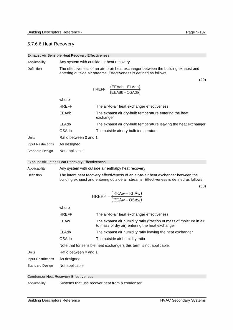
Building Descriptors Reference - Page 5-137
Building Descriptors Reference HVAC Secondary Systems
5.7.6.6 Heat Recovery
Exhaust Air Sensible Heat Recovery Effectiveness
Any system with outside air heat recovery
The effectiveness of an air-to-air heat exchanger between the building exhaust andentering outside air streams. Effectiveness is defined as follows:
(49)
OSAdbEEAdb
ELAdbEEAdbHREFF
where
HREFF The air-to-air heat exchanger effectiveness
EEAdb The exhaust air dry-bulb temperature entering the heatexchanger
ELAdb The exhaust air dry-bulb temperature leaving the heat exchanger
OSAdb The outside air dry-bulb temperature
Ratio between 0 and 1
As designed
Not applicable
Exhaust Air Latent Heat Recovery Effectiveness
Any system with outside air enthalpy heat recovery
The latent heat recovery effectiveness of an air-to-air heat exchanger between thebuilding exhaust and entering outside air streams. Effectiveness is defined as follows:
(50)
OSAwEEAw
ELAwEEAwHREFF
where
HREFF The air-to-air heat exchanger effectiveness
EEAw The exhaust air humidity ratio (fraction of mass of moisture in airto mass of dry air) entering the heat exchanger
ELAdb The exhaust air humidity ratio leaving the heat exchanger
OSAdb The outside air humidity ratio
Note that for sensible heat exchangers this term is not applicable.
Ratio between 0 and 1
As designed
Not applicable
Condenser Heat Recovery Effectiveness
Systems that use recover heat from a condenser
Applicability
Definition
Units
Input Restrictions
Standard Design
Applicability
Definition
Units
Input Restrictions
Standard Design
Applicability
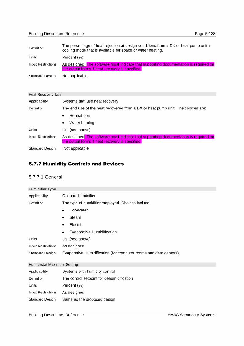
Building Descriptors Reference - Page 5-138
Building Descriptors Reference HVAC Secondary Systems
The percentage of heat rejection at design conditions from a DX or heat pump unit incooling mode that is available for space or water heating.
Percent (%)
As designed. The software must indicate that supporting documentation is required onthe output forms if heat recovery is specified.
Not applicable
Heat Recovery Use
Systems that use heat recovery
The end use of the heat recovered from a DX or heat pump unit. The choices are:
Reheat coils
Water heating
List (see above)
As designed. The software must indicate that supporting documentation is required onthe output forms if heat recovery is specified.
Not applicable
5.7.7 Humidity Controls and Devices
5.7.7.1 General
Humidifier Type
Optional humidifier
The type of humidifier employed. Choices include:
Hot-Water
Steam
Electric
Evaporative Humidification
List (see above)
As designed
Evaporative Humidification (for computer rooms and data centers)
Humidistat Maximum Setting
Systems with humidity control
The control setpoint for dehumidification
Percent (%)
As designed
Same as the proposed design
Definition
Units
Input Restrictions
Standard Design
Applicability
Definition
Units
Input Restrictions
Standard Design
Applicability
Definition
Units
Input Restrictions
Standard Design
Applicability
Definition
Units
Input Restrictions
Standard Design

Building Descriptors Reference - Page 5-139
Building Descriptors Reference HVAC Secondary Systems
Humidistat Minimum Setting
Systems with humidity control
The control setpoint for humidification
Percent (%)
As designed
Same as proposed design
5.7.7.2 Desiccant
Desiccant Type
Systems with desiccant dehumidification
Describes the configuration of desiccant cooling equipment
The following configurations for desiccant systems are allowed:
LIQ-VENT-AIR1 – a liquid desiccant dehumidifying unit
LIQ-VENT-AIR2 – a liquid desiccant dehumidifying unit combined with a gas-firedabsorption chiller
SOL-VENT-AIR1 – a solid desiccant dehumidifying unit
NO-DESICCANT – the default, which indicates that no desiccant system ispresent
List (see above)
As designed
Not applicable
Desiccant Control Mode
Systems with desiccant dehumidification
The method of controlling the operation of the desiccant unit. For liquid-based systemsthis can be either:
Dry-bulb – the desiccant unit is turned on whenever the outside air dry-bulbexceeds a set limit.
Evaporative cooling– cycles the desiccant unit on when an evaporative cooler ison to maintain a dewpoint setpoint.
Dewpoint – cycles the desiccant unit on and off to maintain the dewpointtemperature of the supply air.
For solid-based systems the following configurations are possible:
Dehumidification only – the desiccant unit cycles on and off to maintain indoorhumidity levels
Sensible heat exchanger plus regeneration – the desiccant unit includes asensible heat exchanger to precool the hot, dry air leaving the desiccant unit. Theair leaving the exhaust side of the heat exchanger is directed to the desiccant unit
Sensible heat exchanger – the desiccant unit includes a heat exchanger, but theair leaving the exhaust side of the heat exchanger is exhausted to the outdoors
Applicability
Definition
Units
Input Restrictions
Standard Design
Applicability
Definition
Units
Input Restrictions
Standard Design
Applicability
Definition
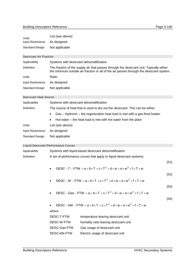
Building Descriptors Reference - Page 5-140
Building Descriptors Reference HVAC Secondary Systems
List (see above)
As designed
Not applicable
Desiccant Air Fraction
Systems with desiccant dehumidification
The fraction of the supply air that passes through the desiccant unit. Typically eitherthe minimum outside air fraction or all of the air passes through the desiccant system.
Ratio
As designed
Not applicable
Desiccant Heat Source
Systems with desiccant dehumidification
The source of heat that is used to dry out the desiccant. This can be either:
Gas – Hydronic – the regeneration heat load is met with a gas-fired heater
Hot water – the heat load is met with hot water from the plant
List (see above)
As designed
Not applicable
Liquid Desiccant Performance Curves
Systems with liquid-based desiccant dehumidification
A set of performance curves that apply to liquid desiccant systems.
(51)
wTfwewdTcTbaFTWTDESC 22
(52)
wTfwewdTcTbaFTWWDESC 22
(53)
wTfwewdTcTbaFTWGasDESC 22
(54)
wTfwewdTcTbaFTWkWDESC 22
where
DESC-T-FTW temperature leaving desiccant unit
DESC-W-FTW humidity ratio leaving desiccant unit
DESC-Gas-FTW Gas usage of desiccant unit
DESC-kW-FTW Electric usage of desiccant unit
Units
Input Restrictions
Standard Design
Applicability
Definition
Units
Input Restrictions
Standard Design
Applicability
Definition
Units
Input Restrictions
Standard Design
Applicability
Definition

Building Descriptors Reference - Page 5-141
Building Descriptors Reference HVAC Secondary Systems
T entering air temperature
w entering humidity ratio
Table 44 – Liquid Desiccant Unit Performance CurvesCoefficient DESC-T-FTW DESC-W-FTW DESC-Gas-FTW DESC-kW-FTW
a 11.5334997 11.8993998 58745.8007813 3.5179000
b 0.6586730 -0.2695580 -1134.4899902 -0.0059317
c -0.0010280 0.0044549 -3.6676099 0.0000000
d 0.2950410 0.0830525 3874.5900879 0.0040401
e -0.0001700 0.0006974 -1.6962700 0.0000000
f -0.0008724 0.0015879 -13.0732002 0.0000000
Data structure
As designed, default to values in Table 44
Not applicable
Desiccant Dewpoint Temperature Setpoint
Systems with desiccant dehumidification
The setpoint dewpoint temperature of the air leaving the desiccant system
Degrees Fahrenheit (°F)
As designed. Defaults to 50°F.
Not applicable
Desiccant Heat Exchanger Effectiveness
Systems with desiccant dehumidification
The effectiveness of a sensible heat exchanger used with a desiccant system
Ratio
As designed
Not applicable
Desiccant Heat Exchanger Pressure Drop
Systems with desiccant dehumidification
The pressure drop across a sensible heat exchanger used with a desiccant system
in. H2O
As designed. Defaults to 1.0 in. H2O
Not applicable
Units
Input Restrictions
Standard Design
Applicability
Definition
Units
Input Restrictions
Standard Design
Applicability
Definition
Units
Input Restrictions
Standard Design
Applicability
Definition
Units
Input Restrictions
Standard Design

Building Descriptors Reference - Page 5-142
Building Descriptors Reference HVAC Primary Systems
5.8 HVAC Primary Systems
5.8.1 Boilers
Boiler Name
All boilers
A unique descriptor for each boiler, heat pump, central heating heat-exchanger or heatrecovery device.
None
User entry. Where applicable, this should match the tags that are used on the plans forthe proposed design.
Boilers are only designated in the baseline model if the Baseline System is of type 1(PTAC), type 5 (Packages VAV with Reheat) or type 6 (VAV with Reheat).
Boiler Fuel
All boilers
The fuel source for the central heating equipment. The choices are:
Gas
Oil
Electricity
List (see above)
As designed
Same fuel as the proposed design
Boiler Type
All boilers
The boiler type. Choices include:
Steam Boiler
Hot Water Boiler
Heat-Pump Water Heater
List (see above)
As designed
The boiler type will be a hot water boiler for baseline systems 1, 5 and 7 All othersystem types do not have a boiler.
Boiler Draft Type
All boilers
Applicability
Definition
Units
Input Restrictions
Standard Design
Applicability
Definition
Units
Input Restrictions
Standard Design
Applicability
Definition
Units
Input Restrictions
Standard Design
Applicability
Definition

Building Descriptors Reference - Page 5-143
Building Descriptors Reference HVAC Primary Systems
How combustion airflow is drawn through the boiler. Choices are:
Natural (sometimes called atmospheric)
Mechanical
Natural draft boilers use natural convection to draw air for combustion through theboiler. Natural draft boilers are subject to outside air conditions and the temperature ofthe flue gases.
Mechanical draft boilers enhance the air flow in one of three ways: 1) Induced draft,which uses ambient air, a steam jet, or a fan to induce a negative pressure which pullsflow through the exhaust stack; 2) Forced draft, which uses a fan and ductwork tocreate a positive pressure that forces air into the furnace, and 3) Balanced draft, whichuses both induced draft and forced draft methods to bring air through the furnace,usually keeping the pressure slightly below atmospheric.
List (see above)
As designed.
Mechanical (forced).
Number of Identical Boiler Units
All boilers
The number of identical units for staging
Numeric: integer
As designed. Default is 1.
The baseline building shall have one boiler for a when the baseline plant serves aconditioned floor area of 15,000 ft
2or less, and have two equally size boilers for plants
serving more than 15,000 ft2.
Boiler Heat Loss
All boilers
The boiler or heat-exchanger heat loss expressed as a percentage of full load outputcapacity. This loss only occurs when the boiler is firing.
Percent (%)
Default is 2% for electric boilers and heat-exchangers and 0% for fuel-fired boilers. Ifthe user overrides the default, supporting documentation is required.
Prescribed at 2% for electric boilers and heat-exchangers. Prescribed at 0% for fuel-fired boilers, since this loss is already incorporated into the overall thermal efficiency,combustion efficiency or AFUE of the boiler. (THIS IS NOT EXPLICITLY MENTIONED IN THE
2008 T24 ACM.)
Boiler Design Capacity
All boilers
The heating capacity at design conditions
Btu/h
Unmet load hours shall not exceed 300. If they do, the proposed boiler capacity shallbe increased incrementally until the unmet loads are reduced to 300 or less.
Units
Input Restrictions
Standard Design
Applicability
Definition
Units
Input Restrictions
Standard Design
Applicability
Definition
Units
Input Restrictions
Standard Design
Applicability
Definition
Units
Input Restrictions

Building Descriptors Reference - Page 5-144
Building Descriptors Reference HVAC Primary Systems
The boiler is sized to be 25% larger than the peak loads of the baseline building.Baseline boilers shall be sized using weather files containing 99.6% heating designtemperatures and 0.5% dry-bulb and 1% wet-bulb cooling design temperatures.
Boiler Efficiency Type
All boilers
The full load efficiency of a boiler is expressed as one of the following:
Annual Fuel Utilization Efficiency (AFUE) is a measure of the boiler’s efficiencyover a predefined heating season.
Thermal Efficiency (Et) is the ratio of the heat transferred to the water divided bythe heat input of the fuel.
Combustion Efficiency (Ec) is the measure of how much energy is extracted fromthe fuel and is the ratio of heat transferred to the combustion air divided by theheat input of the fuel.
List (see above)
Annual Fuel Utilization Efficiency (AFUE), for all gas and oil-fired boilers with less than300,000 Btu/h capacity.
Thermal Efficiency (Et), for all gas and oil-fired boilers with capacities between 225,000and 2,500,000 Btu/h.
Combustion Efficiency (Ec), for all gas and oil-fired boilers with capacities above2,500,000 Btu/h.
Same as proposed design
Boiler Efficiency
All boilers
The full load efficiency of a boiler at rated conditions (see efficiency type above)expressed as a dimensionless ratio of output over input. The software mustaccommodate input in either Thermal Efficiency (Et) or Annual Fuel UtilizationEfficiency (AFUE). Where AFUE is provided, Et shall be calculated as follows:
(55)
%5.10875.0
%100AFUE80%)2
%5.721.0
80%<AFUE75%1)
AFUEE
AFUEE
t
t
All electric boilers will have an efficiency of 100%.
For applicable software, heat input ratio shall be defined as the inverse of thermalefficiency.
Ratio
As designed
Boilers for the baseline design are assumed to have the minimum efficiency as listedin Table E-4 of the 2009 CEC Appliance Efficiency Standards.
Standard Design
Applicability
Definition
Units
Input Restrictions
Standard Design
Applicability
Definition
Units
Input Restrictions
Standard Design
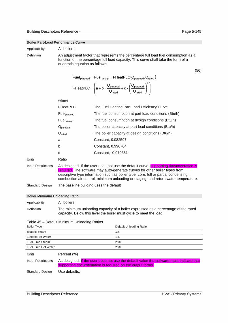
Building Descriptors Reference - Page 5-145
Building Descriptors Reference HVAC Primary Systems
Boiler Part-Load Performance Curve
All boilers
An adjustment factor that represents the percentage full load fuel consumption as afunction of the percentage full load capacity. This curve shall take the form of aquadratic equation as follows:
(56)
2
,
rated
partload
rated
partload
ratedpartloaddesignpartload
Q
Qc
Q
QbaFHeatPLC
QQFHeatPLCFuelFuel
where
FHeatPLC The Fuel Heating Part Load Efficiency Curve
Fuelpartload The fuel consumption at part load conditions (Btu/h)
Fuel design The fuel consumption at design conditions (Btu/h)
Qpartload The boiler capacity at part load conditions (Btu/h)
Qrated The boiler capacity at design conditions (Btu/h)
a Constant, 0.082597
b Constant, 0.996764
c Constant, -0.079361
Ratio
As designed. If the user does not use the default curve, supporting documentation isrequired. The software may auto-generate curves for other boiler types fromdescriptive type information such as boiler type, core, full or partial condensing,combustion air control, minimum unloading or staging, and return water temperature.
The baseline building uses the default
Boiler Minimum Unloading Ratio
All boilers
The minimum unloading capacity of a boiler expressed as a percentage of the ratedcapacity. Below this level the boiler must cycle to meet the load.
Table 45 – Default Minimum Unloading RatiosBoiler Type Default Unloading Ratio
Electric Steam 1%
Electric Hot Water 1%
Fuel-Fired Steam 25%
Fuel-Fired Hot Water 25%
Percent (%)
As designed. If the user does not use the default value the software must indicate thatsupporting documentation is required on the output forms.
Use defaults.
Applicability
Definition
Units
Input Restrictions
Standard Design
Applicability
Definition
Units
Input Restrictions
Standard Design

Building Descriptors Reference - Page 5-146
Building Descriptors Reference HVAC Primary Systems
Hot Water Supply Temperature
All boilers
The temperature of the water produced by the boiler and supplied to the hot water loop
Degrees Fahrenheit (°F)
As designed
Use 180°F for baseline boiler
Hot Water Return Temperature
All boilers
The temperature of the water returning to the boiler from the hot water loop
Degrees Fahrenheit (°F)
As designed
Use 130°F for baseline boiler design.
Hot Water Supply Temperature Reset
All boilers
Variation of the hot water supply temperature with outdoor air temperature.
Degrees Fahrenheit (°F)
As designed
Not applicable
5.8.2 Chillers
Chiller Name
All chillers
A unique descriptor for each chiller
Text, unique
User entry. Where applicable, this should match the tags that are used on the plans.
Chillers are only designated when the baseline system is of type 5 (VAV with reheat)
Chiller Type
All chillers
The type of chiller, either a vapor-compression chiller or an absorption chiller.
Vapor compression chillers operate on the reverse-Rankine cycle, using mechanicalenergy to compress the refrigerant, and include:
Positive displacement – includes reciprocating (piston-style), scroll and screwcompressors
Centrifugal – uses rotating impeller blades to compress the air and impart velocity
Applicability
Definition
Units
Input Restrictions
Standard Design
Applicability
Definition
Units
Input Restrictions
Standard Design
Applicability
Definition
Units
Input Restrictions
Standard Design
Applicability
Definition
Units
Input Restrictions
Standard Design
Applicability
Definition

Building Descriptors Reference - Page 5-147
Building Descriptors Reference HVAC Primary Systems
Single Effect Absorption – use a single generator & condenser
Double Effect Absorption – use two generators/concentrators and condensers,one at a lower temperature and the other at a higher temperature. It is moreefficient than the single effect, but it must use a higher temperature heat source.
Double Effect Absorption, Indirect-Fired
Gas Engine Driven Chiller
List (see above)
As designed
The baseline building chiller is based on the design capacity of the proposed design asfollows:
Table 46 – Type and Number of Chillers
Building Peak Cooling Load Number and Type of Chiller(s)
<= 300 tons 1 water-cooled screw chiller
>300 tons, < 600 tons 2 water-cooled screw chillers, sized equally
>= 600 tons A minimum of two (2) water-cooled centrifugal chillers, sized tokeep the unit size below 800 tons
Number of Identical Chiller Units
All chillers
The number of identical units for staging.
None
As designed. Default is 1.
From Table 46 above, there is one chiller if the baseline system cooling load is 300tons or less and two equally sized chillers for baseline system loads between 300 and600 tons. For loads above 600 tons, two or more chillers of equal size are used, withno chiller larger than 800 tons.
Chiller Fuel
All chillers
The fuel source for the chiller. The choices are:
Electricity (for all vapor-compression chillers)
Gas (Absorption units only, designated as direct-fired units)
Oil (Absorption units only, designated as direct-fired units)
Hot Water (Absorption units only, designated as indirect-fired units)
Steam (Absorption units only, designated as indirect-fired units)
List (see above)
As designed.
Electricity
Units
Input Restrictions
Standard Design
Applicability
Definition
Units
Input Restrictions
Standard Design
Applicability
Definition
Units
Input Restrictions
Standard Design

Building Descriptors Reference - Page 5-148
Building Descriptors Reference HVAC Primary Systems
Chiller Rated Capacity
All chillers
The cooling capacity of a piece of heating equipment at rated conditions.
Btu/h or tons
As designed. If unmet load hours are greater than 300, the chiller may have to bemade larger.
Determine loads for baseline building and oversize by 15%.
Chiller Rated Efficiency
All chillers
The Efficiency of the chiller (Coefficient of Performance (COP) for air-cooled chillersand kW/ton for water-cooled, positive displacement chillers) at ARI 550/590 rated full-load conditions.
Ratio (kW/ton or COP)
As designed. Must meet the minimum requirements of Table 110.2-D.
Use the minimum efficiency requirements from Tables 110.2-D Path B.
Integrated Part-Load Value
All chillers
The part-load efficiency of a chiller developed from a weighted average of four ratingconditions, according to ARI Standard 550..
Ratio (kW/ton)
As designed. Must meet the minimum requirements of Table 110.2-D.
Not used. The proposed design input for IPLV, along with the Chiller Rated Efficiency,determines whether the chiller performance curves will use Path A or Path B.
Chiller Minimum Unloading Ratio
All chillers
The minimum unloading capacity of a chiller expressed as a fraction of the ratedcapacity. Below this level the chiller must cycle to meet the load.
Table 47 – Default Minimum Unloading RatiosChiller Type Default Unloading Ratio
Reciprocating 25%
Screw 15%
Centrifugal 10%
Scroll 25%
Single Effect Absorption 10%
Double Effect Absorption 10%
Percent (%)
As designed. If the user does not employ the default values, supporting documentationis required.
Use defaults listed above.
Applicability
Definition
Units
Input Restrictions
Standard Design
Applicability
Definition
Units
Input Restrictions
Standard Design
Applicability
Definition
Units
Input Restrictions
Standard Design
Applicability
Definition
Units
Input Restrictions
Standard Design

Building Descriptors Reference - Page 5-149
Building Descriptors Reference HVAC Primary Systems
Chiller Cooling Capacity Adjustment Curve
All chillers
A curve or group of curves or other functions that represent the available total coolingcapacity as a function of evaporator and condenser conditions and perhaps otheroperating conditions. The default curves are given as follows:
(57)
ratedavailable QFTCAPQ _
For air-cooled chillers:
(58)
odbchwsodbodbchwschws ttftetdtctbaFTCAP 22
_
For water-cooled chillers:
(59)
cwschwscwscwschwschws ttftetdtctbaFTCAP 22
_
where
Qavailable Available cooling capacity at present evaporator and condenserconditions (MBH)
tchws The chilled water supply temperature (°F)
tcws The condenser water supply temperature (°F)
todb The outside air dry-bulb temperature (°F)
Qrated Rated capacity at ARI conditions (MBH)
Note: If an air-cooled unit employs an evaporative condenser, todb is the effective dry-bulb temperature of the air leaving the evaporative cooling unit.
Separate curves are provided for Path A and Path B chillers in Appendix 5.7.
Applicability
Definition

Building Descriptors Reference - Page 5-150
Building Descriptors Reference HVAC Primary Systems
Table 48 – Default Capacity Coefficients – Electric Air-Cooled ChillersCoefficient Scroll Recip Screw Centrifugal
a 0.40070684 0.57617295 -0.09464899 N/A
b 0.01861548 0.02063133 0.03834070 N/A
c 0.00007199 0.00007769 -0.00009205 N/A
d 0.00177296 -0.00351183 0.00378007 N/A
e -0.00002014 0.00000312 -0.00001375 N/A
f -0.00008273 -0.00007865 -0.00015464 N/A
Table 49 – Default Capacity Coefficients – Electric Water-Cooled ChillersCoefficient Scroll Recip Screw Centrifugal
a 0.36131454 0.58531422 0.33269598 -0.29861976
b 0.01855477 0.01539593 0.00729116 0.02996076
c 0.00003011 0.00007296 -0.00049938 -0.00080125
d 0.00093592 -0.00212462 0.01598983 0.01736268
e -0.00001518 -0.00000715 -0.00028254 -0.00032606
f -0.00005481 -0.00004597 0.00052346 0.00063139
Table 50 – Default Capacity Coefficients – Fuel- & Steam-Source Water-Cooled ChillersCoefficient Single Stage Absorption Double Stage Absorption Direct-Fired Absorption Engine Driven Chiller
A 0.723412 -0.816039 1.000000 0.573597
B 0.079006 -0.038707 0.000000 0.0186802
C -0.000897 0.000450 0.000000 0.000000
D -0.025285 0.071491 0.000000 -0.00465325
E -0.000048 -0.000636 0.000000 0.000000
F 0.000276 0.000312 0.000000 0.000000
Data structure
Default curves are provided in Appendix 5.7. If the default curves are overridden,supporting documentation is required.
Use default curve for Path A and Path B chiller as applicable.
Electric Chiller Cooling Efficiency Adjustment Curves
All chillers
A curve or group of curves that varies the cooling efficiency of an electric chiller as afunction of evaporator conditions, condenser conditions and part-load ratio. Note thatfor variable-speed chillers, the part-load cooling efficiency curve is a function of bothpart-load ratio and leaving condenser water temperature. The default curves are givenas follows:
Units
Input Restrictions
Standard Design
Applicability
Definition

Building Descriptors Reference - Page 5-151
Building Descriptors Reference HVAC Primary Systems
(60)
FTCAPFTEIRFPLREIRPP
ttftetdtctbaFTEIR
ttftetdtctbaFTEIR
PLRtjtPLRith
PLRgtPLRftetdPLRcPLRbaFPLREIR
PLRcPLRbaFPLREIR
ttQ
QPLR
ratedoperating
cwschwscwscwschwschws
odbchwsodbodbchwschws
cwscwscws
cwscwscws
odbcwschwsavailable
operating
___
_cooled-water
_cooled-air
_speed-variable
_
,
22
22
223
322
2
/
where
PLR Part load ratio based on available capacity (not rated capacity)
Qoperating Present load on chiller (Btu/h)
Qavailable Chiller available capacity at present evaporator and condenserconditions (Btu/h)
tchws The chilled water supply temperature (°F)
tcws The condenser water supply temperature (°F)
todb The outside air dry-bulb temperature (°F)
Prated Rated power draw at ARI conditions (kW)
Poperating Power draw at specified operating conditions (kW)
Note: If an air-cooled chiller employs an evaporative condenser, todb is the effectivedry-bulb temperature of the air leaving the evaporative cooling unit.
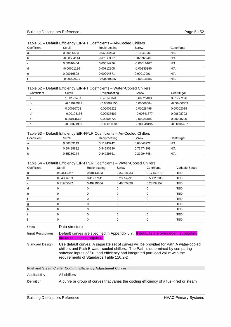
Building Descriptors Reference - Page 5-152
Building Descriptors Reference HVAC Primary Systems
Table 51 – Default Efficiency EIR-FT Coefficients – Air-Cooled ChillersCoefficient Scroll Reciprocating Screw Centrifugal
a 0.99006553 0.66534403 0.13545636 N/A
b -0.00584144 -0.01383821 0.02292946 N/A
c 0.00016454 0.00014736 -0.00016107 N/A
d -0.00661136 0.00712808 -0.00235396 N/A
e 0.00016808 0.00004571 0.00012991 N/A
f -0.00022501 -0.00010326 -0.00018685 N/A
Table 52 – Default Efficiency EIR-FT Coefficients – Water-Cooled ChillersCoefficient Scroll Reciprocating Screw Centrifugal
a 1.00121431 0.46140041 0.66625403 0.51777196
b -0.01026981 -0.00882156 0.00068584 -0.00400363
c 0.00016703 0.00008223 0.00028498 0.00002028
d -0.00128136 0.00926607 -0.00341677 0.00698793
e 0.00014613 0.00005722 0.00025484 0.00008290
f -0.00021959 -0.00011594 -0.00048195 -0.00015467
Table 53 – Default Efficiency EIR-FPLR Coefficients – Air-Cooled ChillersCoefficient Scroll Reciprocating Screw Centrifugal
a 0.06369119 0.11443742 0.03648722 N/A
b 0.58488832 0.54593340 0.73474298 N/A
c 0.35280274 0.34229861 0.21994748 N/A
Table 54 – Default Efficiency EIR-FPLR Coefficients – Water-Cooled ChillersCoefficient Scroll Reciprocating Screw Centrifugal Variable-Speed
a 0.04411957 0.08144133 0.33018833 0.17149273 TBD
b 0.64036703 0.41927141 0.23554291 0.58820208 TBD
c 0.31955532 0.49939604 0.46070828 0.23737257 TBD
d 0 0 0 0 TBD
e 0 0 0 0 TBD
f 0 0 0 0 TBD
g 0 0 0 0 TBD
h 0 0 0 0 TBD
i 0 0 0 0 TBD
j 0 0 0 0 TBD
Data structure
Default curves are specified in Appendix 5.7. If defaults are overridden, supportingdocumentation is required.
Use default curves. A separate set of curves will be provided for Path A water-cooledchillers and Path B water-cooled chillers. The Path is determined by comparingsoftware inputs of full-load efficiency and integrated part-load value with therequirements of Standards Table 110.2-D.
Fuel and Steam Chiller Cooling Efficiency Adjustment Curves
All chillers
A curve or group of curves that varies the cooling efficiency of a fuel-fired or steam
Units
Input Restrictions
Standard Design
Applicability
Definition

Building Descriptors Reference - Page 5-153
Building Descriptors Reference HVAC Primary Systems
chiller as a function of evaporator conditions, condenser conditions, and part-loadratio. The default curves are given as follows:
Default Curves for Steam-Driven Single and Double Effect Absorption Chillers
(61)
FTCAPFTFIRFPLRFIRFuelFuel
ttftetdtctbaFTFIR
PLRcPLRbaFPLRFIR
ttQ
QPLR
ratedpartload
cwschwscwscwschwschws
odbcwschwsavailable
operating
___
_
_
,
22
2
/
Default Curves for Direct-Fired Double Effect Absorption Chillers
(62)
FTCAPFTFIRFTFIRFPLRFIRFuelFuel
tftedFTFIR
tctbaFTFIR
PLRcPLRbaFPLRFIR
ttQ
QPLR
ratedpartload
cwscws
chwschws
odbcwschwsavailable
operating
_2_1__
2_
1_
_
,
2
2
2
/
The default curves for engine driven chillers are the same format as those for theSteam-Driven Single and Double Effect Absorption Chillers but there are three sets ofcurves for different ranges of operation based on the engine speed.
where
PLR Part load ratio based on available capacity (not rated capacity)
FIR-FPLR A multiplier on the fuel input ratio (FIR) to account for part loadconditions
FIR-FT A multiplier on the fuel input ratio (FIR) to account for the chillerwater supply temperature and the condenser water temperature
FIR-FT1 A multiplier on the fuel input ratio (FIR) to account for chilledwater supply temperature
FIR-FT2 A multiplier on the fuel input ratio (FIR) to account for condenserwater supply temperature
CAP-FT A multiplier on the capacity of the chiller (see Equation (58))
Qoperating Present load on chiller (in Btu/h)
Qavailable Chiller available capacity at present evaporator and condenserconditions (in Btu/h)
tchws The chilled water supply temperature (in °F)
tcws The condenser water supply temperature (in °F)
todb The outside air dry-bulb temperature (°F)
Fuelrated Rated fuel consumption at ARI conditions (in Btu/h)
Fuelpartload Fuel consumption at specified operating conditions (in Btu/h)

Building Descriptors Reference - Page 5-154
Building Descriptors Reference HVAC Primary Systems
Table 55 – Default FIR-FPLR coefficients – Fuel- & Steam-Source Water-Cooled Absorption ChillersCoefficient Single Stage Absorption Double Stage Absorption Direct-Fired Absorption
a 0.098585 0.013994 0.13551150
b 0.583850 1.240449 0.61798084
c 0.560658 -0.914883 0.24651277
d -0.243093 0.660441 0.00000000
Table 56 – Default FIR-FPLR coefficients – Engine Driven ChillersCoefficient %SpeedMin. %Speed>Min.
%Speed<60%
%Speed>60%
a 0.3802 1.14336 1.38861
b 2.3609 0.022889 -0.388614
c 0.0000 0.0000 0.0000
d 0.0000 0.0000 0.0000
Table 57 – Default FIR-FT coefficients – Fuel- & Steam-Source Water-Cooled Absorption ChillersCoefficient Single Stage Absorption Double Stage Absorption Direct-Fired Absorption
a 0.652273 1.658750 4.42871284
b 0.000000 0.000000 -0.13298607
c 0.000000 0.000000 0.00125331
d -0.000545 -0.290000 0.86173749
e 0.000055 0.000250 -0.00708917
f 0.000000 0.000000 0.0010251
Table 58 – Default FIR-FT coefficients – Engine Driven ChillersCoefficient %SpeedMin. %Speed>Min.
%Speed<60%
%Speed>60%
A 1.0881500 1.2362400 1.2362400
B 0.0141064 0.0168923 0.0168923
C 0.0000000 0.0000000 0.0000000
D -0.00833912 -0.0115235 -0.0115235
E 0.0000000 0.0000000 0.0000000
F 0.0000000 0.0000000 0.0000000
Data structure
User may input curves or use default curves. If defaults are overridden, supportingdocumentation is required.
Use default curves.
Chilled Water Supply Temperature
All chillers
The chilled water supply temperature of the chiller at design conditions
Degrees Fahrenheit (°F)
As designed
Units
Input Restrictions
Standard Design
Applicability
Definition
Units
Input Restrictions
Standard Design

Building Descriptors Reference - Page 5-155
Building Descriptors Reference HVAC Primary Systems
The baseline chilled water supply temperature is set to 44°F.
Chilled Water Return Temperature
All chillers
The chilled water return temperature setpoint
Degrees Fahrenheit (°F)
As designed
The baseline chilled water return temperature is set to 64°F.
Chilled Water Supply Temperature Reset
All chillers
The reset schedule for the chilled water supply temperature. The chilled water setpointmay be reset based on demand or outdoor air temperature.
Degrees Fahrenheit (°F)
As designed..
Demand-based reset, up to 10°F from design chilled water supply temperature
Condenser Type
All chillers
The type of condenser for a chiller. The choices are:
Air-Cooled
Water-Cooled
Evaporatively-Cooled
Air-cooled chillers use air to cool the condenser coils. Water-cooled chillers use coldwater to cool the condenser and additionally need either a cooling tower or a localsource of cold water. Evaporatively-cooled chillers are similar to air-cooled chillers,except they use a water mist to cool the condenser coil which makes them moreefficient.
List (see above)
As designed
The baseline chiller is always assumed to have a water-cooled condenser, althoughthe chiller type will change depending on the design capacity.
Air-Cooled Condenser Power
All chillers with air-cooled condensers where fan energy is not part of the COP.
The energy usage of the condenser fan(s) at design conditions on an air-cooled chiller.This unit should only be used for chillers composed of separate evaporator andcondenser sections where the fan energy is not part of the chiller COP.
Kilowatts (kW)
As designed. The user must enter data for remote air-cooled condensing units.
Not applicable, since all baseline chillers have water-cooled condensers.
Applicability
Definition
Units
Input Restrictions
Standard Design
Applicability
Definition
Units
Input Restrictions
Standard Design
Applicability
Definition
Units
Input Restrictions
Standard Design
Applicability
Definition
Units
Input Restrictions
Standard Design

Building Descriptors Reference - Page 5-156
Building Descriptors Reference HVAC Primary Systems
5.8.3 Cooling Towers
Baseline Building Summary. Baseline building system 6 has one or more cooling towers. One tower isassumed to be matched to each baseline building chiller. Each baseline building chiller has its owncondenser water pump that operates when the chiller is brought into service. The range between thecondenser water return (CWR) and condenser water supply (CWS) is 12 F. The baseline buildingpumping energy is assumed to be 12 W/gpm. The baseline building cooling tower is assumed to have avariable-speed fan that is controlled to provide a CWS equal to the design dry-bulb temperature whenweather permits. The tower fan modulates to maintain a CWS of the design wet-bulb temperature at lowwet-bulb conditions. Under cooling conditions closer to design conditions, the CWS floats up to amaximum of 85 F (the design condition).
Cooling Tower Name
All cooling towers
A unique descriptor for each cooling tower
Text, unique
User entry. Where applicable, this should match the tags that are used on the plans.
Descriptive name that keys the baseline building plant
Cooling Tower Type
All cooling towers
The type of cooling tower employed. The choices are:
Open tower, centrifugal fan
Open tower, axial fan
Closed tower, centrifugal fan
Closed tower, axial fan
Open cooling towers collect the cooled water from the tower and pump it directly backto the cooling system. Closed towers circulate the evaporated water over a heatexchanger to indirectly cool the system fluid.
List (see above)
As designed
The baseline cooling tower is an open tower axial fan device
Cooling Tower Capacity
All cooling towers
The tower thermal capacity per cell adjusted to CTI (Cooling Technology Institute)rated conditions of 95 F condenser water return, 85 F condenser water supply, and 78F wet-bulb with a 3 gpm/nominal ton water flow. The default cooling tower curvesbelow are at unity at these conditions.
Btu/h
As designed
The baseline building chiller is autosized and increased by 15%. The tower is sized tosupply 85 F condenser water at design conditions for the oversized chiller.
Applicability
Definition
Units
Input Restrictions
Standard Design
Applicability
Definition
Units
Input Restrictions
Standard Design
Applicability
Definition
Units
Input Restrictions
Standard Design

Building Descriptors Reference - Page 5-157
Building Descriptors Reference HVAC Primary Systems
Cooling Tower Number of Cells
All cooling towers
The number of cells in the cooling tower. Each cell will be modeled as equal size. Cellsare subdivisions in cooling towers into individual cells, each with their own fan andwater flow, and allow the cooling system to respond more efficiently to lower loadconditions.
Numeric: integer
As designed
Same as the proposed design.
Cooling Tower Total Fan Horse Power
All cooling towers
The sum of the nameplate rated horsepower (hp) of all fan motors on the coolingtower. Pony motors should not be included.
Gpm/hp or unitless if energy input ratio (EIR) is specified (If the nominal tons but notthe condenser water flow is specified, the condenser design water flow shall be 3.0gpm per nominal cooling ton.)
As designed, but the cooling towers shall meet minimum performance requirements inTable 110.2-G.
The cooling tower fan horsepower is 60 gpm/hp.
.
Cooling Tower Design Wet-Bulb
All cooling towers
The design wet-bulb temperature that was used for selection and sizing of the coolingtower.
Degrees Fahrenheit (°F)
As designed, based on the design conditions from Reference Appendix JA2 for the citymost closely corresponding to local conditions.
Same as proposed design
Cooling Tower Design Entering Water Temperature
All cooling towers
The design condenser water supply temperature (leaving tower) that was used forselection and sizing of the cooling tower.
Degrees Fahrenheit (°F)
As designed. Default to 85°F.
85°F or 10°F above the design wet-bulb temperature, whichever is lower
Cooling Tower Design Return Water Temperature
All cooling towers
The design condenser water return temperature (entering tower) that was used for
Applicability
Definition
Units
Input Restrictions
Standard Design
Applicability
Definition
Units
Input Restrictions
Standard Design
Applicability
Definition
Units
Input Restrictions
Standard Design
Applicability
Definition
Units
Input Restrictions
Standard Design
Applicability
Definition
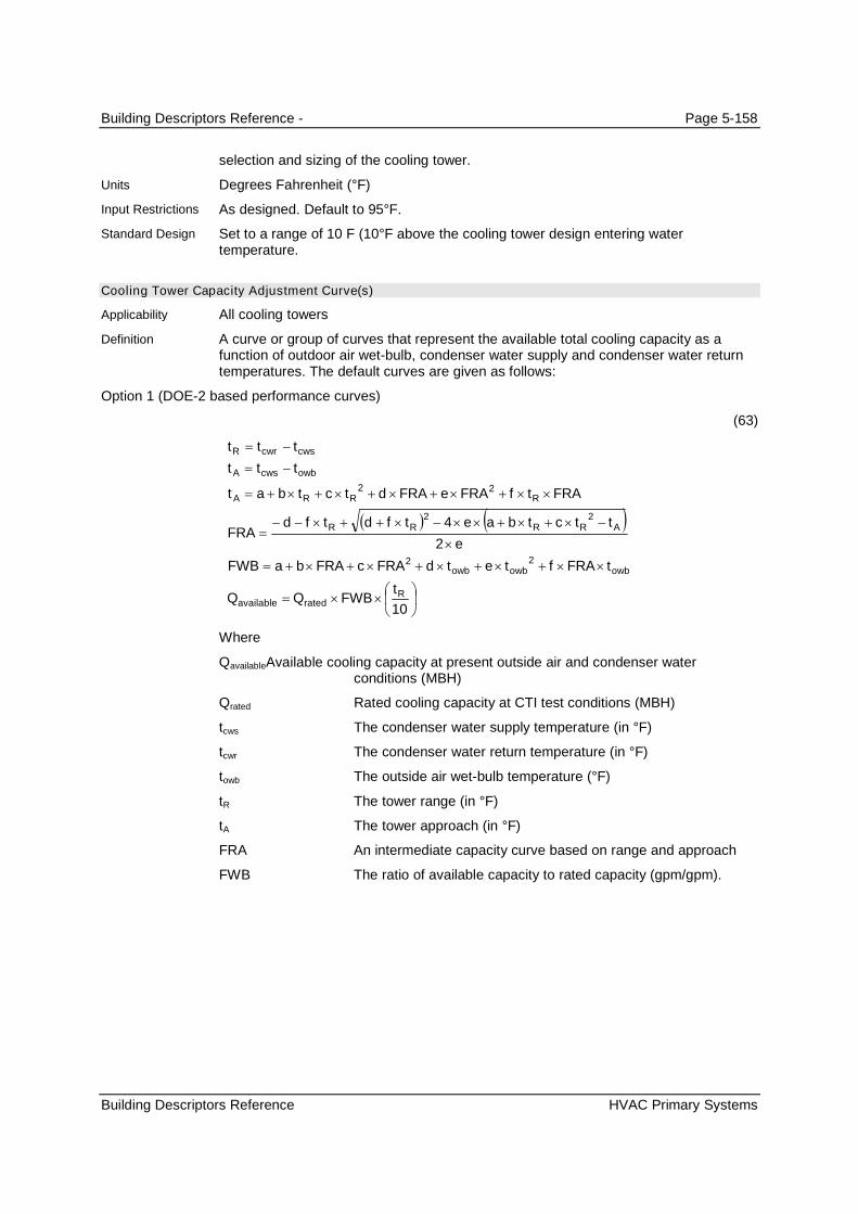
Building Descriptors Reference - Page 5-158
Building Descriptors Reference HVAC Primary Systems
selection and sizing of the cooling tower.
Degrees Fahrenheit (°F)
As designed. Default to 95°F.
Set to a range of 10 F (10°F above the cooling tower design entering watertemperature.
Cooling Tower Capacity Adjustment Curve(s)
All cooling towers
A curve or group of curves that represent the available total cooling capacity as afunction of outdoor air wet-bulb, condenser water supply and condenser water returntemperatures. The default curves are given as follows:
Option 1 (DOE-2 based performance curves)
(63)
10
2
4
22
22
22
Rratedavailable
owbowbowb
ARRRR
RRRA
owbcwsA
cwscwrR
tFWBQQ
tFRAftetdFRAcFRAbaFWB
e
ttctbaetfdtfdFRA
FRAtfFRAeFRAdtctbat
ttt
ttt
Where
QavailableAvailable cooling capacity at present outside air and condenser waterconditions (MBH)
Qrated Rated cooling capacity at CTI test conditions (MBH)
tcws The condenser water supply temperature (in °F)
tcwr The condenser water return temperature (in °F)
towb The outside air wet-bulb temperature (°F)
tR The tower range (in °F)
tA The tower approach (in °F)
FRA An intermediate capacity curve based on range and approach
FWB The ratio of available capacity to rated capacity (gpm/gpm).
Units
Input Restrictions
Standard Design
Applicability
Definition
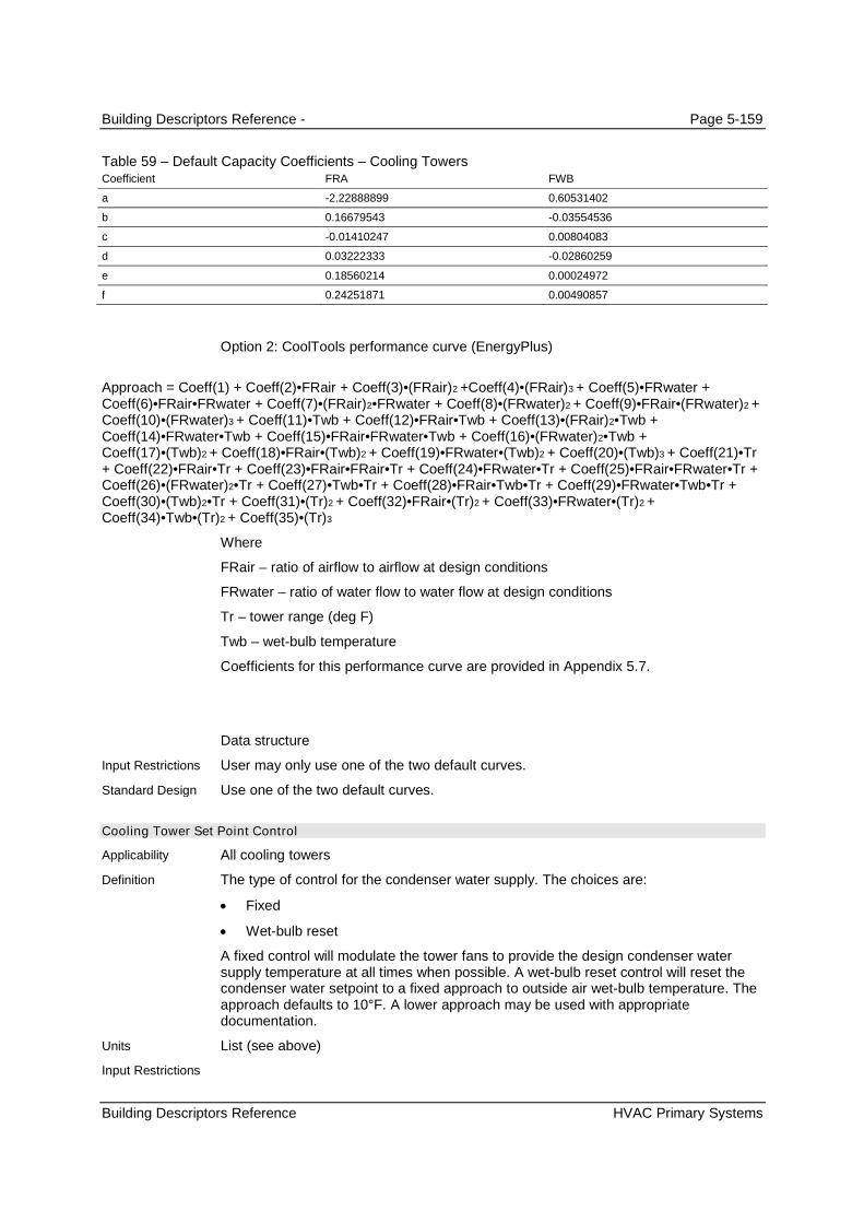
Building Descriptors Reference - Page 5-159
Building Descriptors Reference HVAC Primary Systems
Table 59 – Default Capacity Coefficients – Cooling TowersCoefficient FRA FWB
a -2.22888899 0.60531402
b 0.16679543 -0.03554536
c -0.01410247 0.00804083
d 0.03222333 -0.02860259
e 0.18560214 0.00024972
f 0.24251871 0.00490857
Option 2: CoolTools performance curve (EnergyPlus)
Approach = Coeff(1) + Coeff(2)•FRair + Coeff(3)•(FRair)2 +Coeff(4)•(FRair)3 + Coeff(5)•FRwater +Coeff(6)•FRair•FRwater + Coeff(7)•(FRair)2•FRwater + Coeff(8)•(FRwater)2 + Coeff(9)•FRair•(FRwater)2 +Coeff(10)•(FRwater)3 + Coeff(11)•Twb + Coeff(12)•FRair•Twb + Coeff(13)•(FRair)2•Twb +Coeff(14)•FRwater•Twb + Coeff(15)•FRair•FRwater•Twb + Coeff(16)•(FRwater)2•Twb +Coeff(17)•(Twb)2 + Coeff(18)•FRair•(Twb)2 + Coeff(19)•FRwater•(Twb)2 + Coeff(20)•(Twb)3 + Coeff(21)•Tr+ Coeff(22)•FRair•Tr + Coeff(23)•FRair•FRair•Tr + Coeff(24)•FRwater•Tr + Coeff(25)•FRair•FRwater•Tr +Coeff(26)•(FRwater)2•Tr + Coeff(27)•Twb•Tr + Coeff(28)•FRair•Twb•Tr + Coeff(29)•FRwater•Twb•Tr +Coeff(30)•(Twb)2•Tr + Coeff(31)•(Tr)2 + Coeff(32)•FRair•(Tr)2 + Coeff(33)•FRwater•(Tr)2 +Coeff(34)•Twb•(Tr)2 + Coeff(35)•(Tr)3
Where
FRair – ratio of airflow to airflow at design conditions
FRwater – ratio of water flow to water flow at design conditions
Tr – tower range (deg F)
Twb – wet-bulb temperature
Coefficients for this performance curve are provided in Appendix 5.7.
Data structure
User may only use one of the two default curves.
Use one of the two default curves.
Cooling Tower Set Point Control
All cooling towers
The type of control for the condenser water supply. The choices are:
Fixed
Wet-bulb reset
A fixed control will modulate the tower fans to provide the design condenser watersupply temperature at all times when possible. A wet-bulb reset control will reset thecondenser water setpoint to a fixed approach to outside air wet-bulb temperature. Theapproach defaults to 10°F. A lower approach may be used with appropriatedocumentation.
List (see above)
Input Restrictions
Standard Design
Applicability
Definition
Units
Input Restrictions
Building Descriptors Reference - Page 5-160
Building Descriptors Reference HVAC Primary Systems
As designed. If the user does not use the default control, supporting documentation isrequired.
Fixed at the design wet-bulb temperature, as specified in Reference Appendix JA2
Cooling Tower Capacity Control
All cooling towers
Describes the modulation control employed in the cooling tower. Choices include:
Fluid Bypass provides a parallel path to divert some of the condenser wateraround the cooling tower at part-load conditions
Fan Cycling is a simple method of capacity control where the tower fan is cycledon and off. This is and is often used on multiple-cell installations.
Two-Speed Fan/Pony Motor. From an energy perspective, these are the same. Alower horsepower pony motor is an alternative to a two-speed motor; the ponymotor runs at part-load conditions (instead of the full sized motor) and saves fanenergy when the tower load is reduced. Additional building descriptors aretriggered when this method of capacity control is selected.
Variable Speed Fan. A variable frequency drive is installed for the tower fan sothat the speed can be modulated.
List (see above)
As designed.
Variable-speed fan for all motors of 7.5 hp or larger, unless one of the followingexceptions applies:
EXCEPTION 1: heat rejection devices included as an integral part of equipment listedin Table 110.2-A through 110.2-E
Cooling Tower Low-Speed Airflow Ratio
All cooling towers with two-speed or pony motors
The percentage full load airflow that the tower has at low speed or with the pony motoroperating. This is equivalent to the percentage full load capacity when operating at lowspeed.
Ratio
As designed.
0.50
Cooling Tower Low-Speed kW Ratio
All cooling towers
The percentage full load power that the tower fans draw at low speed or with the ponymotor operating
Ratio
Calculated, using the as-designed flow ratio and the cooling tower power adjustmentcurve below..
0.25
Standard Design
Applicability
Definition
Units
Input Restrictions
Standard Design
Applicability
Definition
Units
Input Restrictions
Standard Design
Applicability
Definition
Units
Input Restrictions
Standard Design

Building Descriptors Reference - Page 5-161
Building Descriptors Reference HVAC Primary Systems
Cooling Tower Power Adjustment Curve
All cooling towers with VSD control
A curve that varies the cooling tower fan energy usage as a function of part-load ratiofor cooling towers with variable speed fan control. The default curve is given asfollows:
(64)
FPLRFANTWRPP
PLRdPLRcPLRbaFPLRFANTWR
tttQ
QPLR
ratedoperating
OWBARavailable
operating
__
__
,,32
where
PLR Part load ratio based on available capacity (not rated capacity)
Qoperating Present load on tower (in Btu/h)
Qavailable Tower available capacity at present range, approach, andoutside wet-bulb conditions (in Btu/h).
towb The outside air wet-bulb temperature (°F)
tR The tower range (°F)
tA The tower approach (°F)
Prated Rated power draw at CTI conditions (kW)
Poperating Power draw at specified operating conditions (kW)
Table 60 – Default Efficiency TWR-FAN-FPLR Coefficients – VSD on Cooling Tower FanCoefficient TWR-FAN-FPLR
a 0.33162901
b -0.88567609
c 0.60556507
d 0.9484823
Data structure
User may input curves or use default curves. If defaults are overridden, supportingdocumentation is required.
Use default curves from DOE 2, given above.
Cooling Tower Minimum Speed
All cooling towers with a VSD control
The minimum fan speed setting of a VSD controlling a cooling tower fan expressed asa ratio of full load speed.
Ratio
As designed. The default is 0.40.
Not applicable
Applicability
Definition
Units
Input Restrictions
Standard Design
Applicability
Definition
Units
Input Restrictions
Standard Design

Building Descriptors Reference - Page 5-162
Building Descriptors Reference HVAC Primary Systems
5.8.4 Water-side Economizers
Baseline Building Summary. None of the baseline building systems use a water-side economizer.
Water-Side Economizer Name
All water-side economizers
The name of a water-side economizer for a cooling system
Text, unique
Descriptive reference to the construction documents. The default is no water-sideeconomizer.
No water economizer
Water Economizer Type
All water-side economizers
The type of water-side economizer. Choices include:
None
Heat exchanger in parallel with chillers. This would be used with an open coolingtower is often referred to as a non-integrated economizer, because the chillers arelocked out when the plant is in economizer mode.
Heat exchanger in series with chillers. This would be used with an open coolingtower and is often referred to as an integrated, because the chillers can operatesimultaneously with water economizer operation.
Direct water economizer. This would be used with a closed cooling tower. In thiscase, a heat exchanger is not needed. This type works only as a non-integratedeconomizer. (also known as strainer-cycle)
Thermo-cycle (also known as refrigerant migration). With thermo-cycle, bypassvalves allow for the flow to vapor refrigerant to the condenser and allow gravityflow of liquid refrigerant to the evaporator without use of the compressor. Onlysome chillers have this capability and capacity may be limited under this mode.There is no additional piping; the cooler water from the tower is brought directly tothe chiller(s) and the chiller(s) respond by shutting down the compressor andrelying on thermal forces to drive the refrigerant. This method is also known as“thermosiphon” since thermal gradients passively move refrigerant between theevaporator and condenser.
List (see above)
As designed
No water economizer
Water-Side Economizer HX Effectiveness
Water-side economizers with an open cooling tower
The effectiveness of a water-side heat exchanger at design conditions. This is definedas:
Applicability
Definition
Units
Input Restrictions
Standard Design
Applicability
Definition
Units
Input Restrictions
Standard Design
Applicability
Definition

Building Descriptors Reference - Page 5-163
Building Descriptors Reference HVAC Primary Systems
(65)
ewea
laeaeff
tt
ttWSE
where
WSEeff The effectiveness of the water-side economizer coil
tea The entering coil air dry-bulb temperature (°F)
tla The leaving coil air dry-bulb temperature (°F)
tea The entering coil water temperature (°F)
Ratio
As designed. The default is 60%.
No water economizer
Water-Side Economizer Maximum Tdb
All water-side economizers
The control temperature (outside air dry-bulb temperature) above which the water-sideeconomizer is disabled.
Degrees Fahrenheit (°F)
As designed. Defaults to 65°F.
No water economizer
Water-Side Economizer Maximum CWS
All water-side economizers
The control temperature (condenser water supply temperature) above which thewater-side economizer is disabled.
Degrees Fahrenheit (°F)As designed. Defaults to 50°F.
No water economizer
Water-Side Economizer CWS Setpoint
All water-side economizers
The design condenser water supply temperature for the cooling tower in economizermode.
Degrees Fahrenheit (°F)
As designed. Defaults to 45°F or 40°F for “Thermo Cycle.” If a strainer cycle isspecified, changeover temperature from economizer to mechanical cooling shall be setat 50°F.
No water economizer
Water-Side Economizer Availability Schedule
All water-side economizers
Units
Input Restrictions
Standard Design
Applicability
Definition
Units
Input Restrictions
Standard Design
Applicability
Definition
Units
Input Restrictions
Standard Design
Applicability
Definition
Units
Input Restrictions
Standard Design
Applicability
Definition

Building Descriptors Reference - Page 5-164
Building Descriptors Reference HVAC Primary Systems
A schedule which represents the availability of the water-side economizer
Data structure: schedule, on/off
As designed
No water economizer
Water-Side Economizer Auxiliary kW
Water-side economizers with an open tower
The electrical input (pumps and auxiliaries) for a dedicated pump for the chilled waterside of the heat exchanger. This power is in excess of the condenser water pumps andcooling tower fans for the system during water-side economizer operation.
KW or kW/ton
As designed
No water economizer
5.8.5 Pumps
Baseline Building Summary. Hot water pumping in the baseline building (systems 1, 5, and 6) shall bemodeled as a variable flow primary only system. Two-way valves are assumed at the heating coils with amodulating bypass valve at the end of the loop. The bypass valve shall open as necessary to maintainminimum flow through the boiler when the system is activated. This will establish the minimum flowthrough the system.
Chilled water pumping in the baseline building (system 6) is a primary system. Each chiller has its ownprimary and condenser water pumps that operate when the chiller is activated. The chilled water pumpshall be variable speed and the condenser water pump shall be fixed speed.
General Notes. The building descriptors in this section are repeated for each pumping system. See thePump Service building descriptor for a list of common pump services.
Pump Name
All pumps
A unique descriptor for each pump
Text, unique
User entry. Where applicable, this should match the tags that are used on the plans.
Same as the proposed design. If there is no equivalent in the proposed design, assigna sequential tag to each piece of equipment. The sequential tags should indicate thepump service as part of the descriptor (e.g. CW for condenser water, CHW for chilledwater, or HHW for heating hot water).
Pump Service
All pumps
The service for each pump. Choices include:
Chilled water
Chilled water (primary)
Chilled water (secondary)
Units
Input Restrictions
Standard Design
Applicability
Definition
Units
Input Restrictions
Standard Design
Applicability
Definition
Units
Input Restrictions
Standard Design
Applicability
Definition

Building Descriptors Reference - Page 5-165
Building Descriptors Reference HVAC Primary Systems
Heating water
Heating water (primary)
Heating water (secondary)
Service hot water
Condenser water
Loop water (for hydronic heat pumps)
List (see above)
As designed
As needed by the baseline building system
Number of Pumps
All pumps
The number of identical pumps in service in a particular loop, e.g. the heating hotwater loop, chilled water loop, or condenser water loop
Numeric: integer
As designed
There will be one heating hot water pump for each boiler, one chilled water pump, andone condenser water pump for each chiller.
Water Loop Design
All pumps
The heating and cooling delivery systems can consist of a simple primary loop system,or more complicated primary/secondary loops or primary/secondary/tertiary loops.
List (see above)
As designed
Assume primary loops only for heating hot water. For chilled water loops, a primaryloop design is assumed s.
Pump Motor Modeling Method
All pumps
Software commonly models fans in one of two ways: The simple method is for the userto enter the electric power per unit of flow (W/gpm). This method is commonly used forsmaller systems. A more detailed method requires a specification of the pump head,design flow, impeller and motor efficiency.
List: Power-Per-Unit-Flow or Detailed
Either method may be used, as appropriate.
Detailed
Pump Motor Power-Per-Unit-Flow
All proposed design pumps that use the Power-Per-Unit-Flow method.
The electric power of the pump divided by the flow at design conditions.
Units
Input Restrictions
Standard Design
Applicability
Definition
Units
Input Restrictions
Standard Design
Applicability
Definition
Units
Input Restrictions
Standard Design
Applicability
Definition
Units
Input Restrictions
Standard Design
Applicability
Definition

Building Descriptors Reference - Page 5-166
Building Descriptors Reference HVAC Primary Systems
W/gpm
As designed
Not applicable
Pump Design Head
All baseline building pumps and proposed design pumps that use the Power-Per-Unit-Flow method.
The head of the pump at design flow conditions.
ft of water
As designed
For chilled water pumps, 40 ft plus an additional allowance of 0.03 ft/ton
For condenser water pumps, 54 ft
Impeller Efficiency
All pumps in proposed design that use the detailed modeling method
The full load efficiency of the impeller
Ratio
As designed
70%
Motor Efficiency
All pumps in proposed design that use the detailed modeling method
The full load efficiency of the pump motor
Ratio
As designed
Minimum requirement from Table 26 of the Nonresidential ACM Manual.
Pump Minimum Speed
All two-speed or variable-speed pumps
The minimum pump speed for a two-speed for variable-speed pump. For two-speedpumps this is typically 0.67 or 0.5. Note that the pump minimum speed is notnecessarily the same as the minimum flow ratio, since the system head may change.
Ratio
As designed
The chilled water pumps for baseline buildingsystem 5 has variable speed drive Inthese cases the Pump Minimum Speed shall be 0.10.
Pump Minimum Flow Ratio
Primary Chilled water pumps
Units
Input Restrictions
Standard Design
Applicability
Definition
Units
Input Restrictions
Standard Design
Applicability
Definition
Units
Input Restrictions
Standard Design
Applicability
Definition
Units
Input Restrictions
Standard Design
Applicability
Definition
Units
Input Restrictions
Standard Design
Applicability
Definition

Building Descriptors Reference - Page 5-167
Building Descriptors Reference HVAC Primary Systems
The minimum fraction of design flow that passes through the chiller. minimum pumpspeed for a two-speed for variable-speed pump. Note that the pump minimum speedis not necessarily the same as the minimum flow ratio, since the system head maychange.
Ratio
As designed
0.3
Pump Design Flow (GPM)
All pumps
The flow rate of the pump at design conditions. This is derived from the load, and thedesign supply and return temperatures.
gpm or gpm/ton for condenser and primary chilled water pumps
Not a user input
The temperature change on the evaporator side of the chillers is 20 F (64 F less 44 F)and this equates to a flow of 1.2 gpm/ton. The temperature change on the condenserside of the chillers is 12 F, which equates to a flow of 2.0 gpm/ cooling ton. For hotwater pumps servicing boilers, the flow rate in gpm shall be the boiler capacity in Btu/h/ 15,000, which corresponds to a loop temperature drop of 30°F.
Pump Control Type
All pumps
The type of control for the pump. Choices are:
Fixed speed, fixed flow
Fixed speed, variable flow (the default, with flow control via a valve)
Two-speed
Variable speed, variable flow
None
As designed. The default is “Fixed Speed, Variable Flow” which models the action of aconstant speed pump riding the curve against 2-way control valves.
The hot water and condenser water loops shall be primary loops only. The hot waterpump shall be modeled as a fixed speed, variable flow pump (riding the pump curve).
The chilled water pumps shall be modeled as variable-speed, variable flow, and thecondenser water pumps shall be modeled as fixed speed. The hot water pumps shallbe modeled as fixed-speed, variable flow, riding the curve.
Pump Operation
All pumps
The type of pump operation can be either On-Demand, Standby or Scheduled. On-Demand operation means the pumps are only pumping when their associatedequipment is cycling, so chiller and condenser pumps are on when the chiller is on andthe heating hot water pump operates when its associated boiler is cycling. Standbyoperation allows hot or chilled water to circulate through the primary loop of aprimary/secondary loop system or through a reduced portion of a primary-only system,
Units
Input Restrictions
Standard Design
Applicability
Definition
Units
Input Restrictions
Standard Design
Applicability
Definition
Units
Input Restrictions
Standard Design
Applicability
Definition

Building Descriptors Reference - Page 5-168
Building Descriptors Reference HVAC Primary Systems
assuming the system has appropriate 3-way valves. Scheduled operation means thatthe pumps and their associated equipment are turned completely off according tooccupancy schedules, time of year, or outside conditions. Under scheduled operation,when the systems are on they are assumed to be in On-Demand mode.
List (see above)
As designed
The baseline system pumps are assumed to operate in On-Demand mode. The chilledwater and condenser pumps are tied to the chiller operation, cycling on and off withthe chiller, and the heating hot water pumps are tied to the boiler operation.
Pump Part Load Curve
All pumps
A part-load power curve for the pump
(66)
32 PLRdPLRcPLRbaFPLRPUMPCIRC
(67)
FPLRPUMPCIRCPP designpump
where
PLR Part load ratio (the ratio of operating flow rate in gpm to designflow rate in gpm)
Ppump Pump power draw at part-load conditions (W)
Pdesign Pump power draw at design conditions (W)
Table 61 – Default Part-Load CIRC-PUMP-FPLR Coefficients – VSD on Circulation PumpCoefficient CIRC-PUMP-FPLR
a 0.0015303
b 0.0052081
c 1.1086242
d -0.1163556
Data structure
As designed. Default is curve above.
Use the defaults described above.
5.8.6 Thermal Storage
There are multiple ways to model thermal storage in the proposed design. The baseline building does nothave thermal storage. Stratified storage tanks with a chilled water storage medium are not supported bythe ACM.
Units
Input Restrictions
Standard Design
Applicability
Definition
Units
Input Restrictions
Standard Design

Building Descriptors Reference - Page 5-169
Building Descriptors Reference HVAC Primary Systems
Storage Type
All thermal storage systems
A type of thermal energy storage (TES) that indicates the storage medium.
List
Ice, Chilled Water
No thermal storage systems
Configuration
All thermal storage systems
Indication of how the TES is configured and operated in relation to the chilled watercooling
List
Series, Chiller Upstream
Series, Chiller Downstream
Parallel
No thermal storage systems
Ice Storage Type
All thermal storage systems with Storage Type=Ice
Indication of the storage type for ice storage
List
IceOnCoilExternal
IceOnCoilInternal
No thermal storage systems
Storage Capacity
All thermal storage systems using ice storage
Nominal Storage Capacity of the tank
GJ
None
No thermal storage systems
Tank Volume
All thermal storage systems using ice storage
Nominal Storage Capacity of the tank
m3
None
No thermal storage systems
Applicability
Definition
Units
Input Restrictions
Standard Design
Applicability
Definition
Units
Input Restrictions
Standard Design
Applicability
Definition
Units
Input Restrictions
Standard Design
Applicability
Definition
Units
Input Restrictions
Standard Design
Applicability
Definition
Units
Input Restrictions
Standard Design

Building Descriptors Reference - Page 5-170
Building Descriptors Reference HVAC Primary Systems
CHW Setpoint Schedule
All thermal storage systems using ice storage
Nominal Storage Capacity of the tank
Series, deg F
None
No thermal storage systems
Deadband Temperature Difference
All thermal storage systems using chilled water
The deadband temperature difference between enabling and disabling use of the TESsystem for cooling
Degrees F
None
No thermal storage systems
Minimum Temperature Limit
All thermal storage systems using chilled water
The minimum allowed temperature of the tank, below which charging of the tankcannot occur
Deg F
None
No thermal storage systems
Storage Tank Location Indicator
All thermal storage systems using ice storage
Nominal Storage Capacity of the tank
List
Schedule, Zone, or Exterior.
If Schedule, the ambient temperature schedule must be specified. If Zone, the Zonename must be specified.
No thermal storage systems
Storage Tank Heat Gain Coefficient
All thermal storage systems using chilled water
The heat transfer coefficient between the tank and the ambient surroundings
W/K
None
No thermal storage systems
Applicability
Definition
Units
Input Restrictions
Standard Design
Applicability
Definition
Units
Input Restrictions
Standard Design
Applicability
Definition
Units
Input Restrictions
Standard Design
Applicability
Definition
Units
Input Restrictions
Standard Design
Applicability
Definition
Units
Input Restrictions
Standard Design

Building Descriptors Reference - Page 5-171
Building Descriptors Reference HVAC Primary Systems
Use Side Heat Transfer Effectiveness
All thermal storage systems using chilled water
The heat transfer effectiveness between the use side water and the tank water
none
Between 0 and 1
No thermal storage systems
Use Side Design Flow Rate
All thermal storage systems using chilled water
Design flow rate through the use side of the storage tank
gpm
None
No thermal storage systems
Source Side Heat Transfer Effectiveness
All thermal storage systems using chilled water
The heat transfer effectiveness between the source side water and the tank water
none
Between 0 and 1
No thermal storage systems
Source Side Design Flow Rate
All thermal storage systems using chilled water
Design flow rate through the source side of the storage tank
gpm
None
No thermal storage systems
Tank Recovery Time
All thermal storage systems using ice storage
This is the time in hours for the tank to cool from 14.4°C to 9°C. This input is only usedif the source side design flow rate is not specified.
hours
None
No thermal storage systems
Applicability
Definition
Units
Input Restrictions
Standard Design
Applicability
Definition
Units
Input Restrictions
Standard Design
Applicability
Definition
Units
Input Restrictions
Standard Design
Applicability
Definition
Units
Input Restrictions
Standard Design
Applicability
Definition
Units
Input Restrictions
Standard Design
Building Descriptors Reference - Page 5-172
Building Descriptors Reference HVAC Primary Systems
5.8.7 Heat Recovery Equipment
Heat Recovery Name
All heat recovery systems
A name assigned to a heat recovery system. This would provide a link to theconstruction documents.
Text, unique
As designed
No heat recovery systems
Heat Recovery Device Type
All heat recovery systems
The type of heat recovery equipment. Choices include:
Double-Bundled Chiller
Generator
Engine-Driven Chiller
Air Conditioning Unit
Refrigerated Casework
List (see above)
As designed
Heat recovery systems are not included in the baseline system.
Heat Recovery Loads
All heat recovery systems
The loads met by the heat recovery system. Choices include:
Service water heating
Space heating
Process heating
More than one load may be selected.
List (see above)
As designed
Not required in the baseline system.
5.8.8 Plant Management
Plant management is a method of sequencing equipment. Separate plant management schemes may beentered for chilled water systems, hot water systems, etc. The following building descriptors are specified
Applicability
Definition
Units
Input Restrictions
Standard Design
Applicability
Definition
Units
Input Restrictions
Standard Design
Applicability
Definition
Units
Input Restrictions
Standard Design

Building Descriptors Reference - Page 5-173
Building Descriptors Reference HVAC Primary Systems
for each load range, e.g. when the cooling load is below 300 tons, between 300 tons and 800 tons, andgreater than 800 tons.
Equipment Type Managed
All plant systems
The type of equipment under a plant management control scheme. Choices include:
Chilled water cooling
Hot water space heating
Condenser water heat rejection
Service water heating
Electrical generation
None
As designed
Same as the proposed design
Equipment Schedule
All plant equipment
A schedule which identifies when the equipment is in service.
Data structure
As designed
Where multiple equipment is used, they shall be staged in operation.
Equipment Operation
All plant equipment
Equipment operation can be either On-Demand or Always-On. On-Demand operationmeans the equipment cycles on when it is scheduled to be in service and when it isneeded to meet building loads, otherwise it is off. Always-On means that equipmentruns continuously when it scheduled to be in service.
None
As designed; the default is On-Demand.
Assume On-Demand operation
Equipment Staging Sequence
All plant equipment
The staging sequence for plant equipment (chillers and boilers) indicates how multipleequipment will be staged on and off when a single piece of equipment is unable tomeet the load.
Structure – this should include (a) the percent of capacity above which additionalequipment is staged on; (b) the percent of capacity below which one plant equipmentis staged off
As designed.
Applicability
Definition
Units
Input Restrictions
Standard Design
Applicability
Definition
Units
Input Restrictions
Standard Design
Applicability
Definition
Units
Input Restrictions
Standard Design
Applicability
Definition
Units
Input Restrictions
Building Descriptors Reference - Page 5-174
Building Descriptors Reference Miscellaneous Energy Uses
Compliance software shall bring up each boiler to 90 percent capacity prior to thestaging of the next boiler.
Compliance software shall bring up each chiller to 90 percent capacity prior to thestaging of the next chiller.
5.9 Miscellaneous Energy Uses
Miscellaneous energy uses are defined as those that may be treated separately since they have little orno interaction with the conditioned thermal zones or the HVAC systems that serve them.
5.9.1 Water Heating
Water heating systems shall always be modeled for both the proposed design and baseline building whenthe proposed building is expected to have a water heating load, even if no water heating is shown on theplans or specifications for the proposed design. In such instances, an electric resistance system shall bemodeled for both the proposed design and baseline building, meeting the efficiency requirements of thebaseline standard.
When the construction documents show a water heating system, the layout and configuration of thebaseline building system shall be the same as the proposed design, e.g. the baseline building shall havethe same number of water heaters and the same distribution system.
5.9.1.1 System Loads and Configuration
Water Heating System Name
All water heating systems
A unique descriptor for each water heating system. A system consists of one or morewater heaters, a distribution system, an estimate of hot water use, and a schedule forthat use. Nonresidential buildings will typically have multiple systems, perhaps aseparate electric water heater for each office break room, etc. Other building typessuch as hotels and hospitals may have a single system serving the entire building.
Text, unique
Where applicable, this should match the tags that are used on the plans such that aplan reviewer can make a connection.
The naming convention for the baseline building system shall be similar to theproposed design.
Water Heating Peak Use
All water heating systems, required
An indication of the peak hot water usage (e.g. service to sinks, showers, and kitchenappliances, etc.). When specified per occupant, this value is multiplied by designoccupancy density values and modified by service water heating schedules to obtainhourly load values which are used in the simulation.
Peak consumption is commonly specified as gallons per hour per occupant, dwellingunit, hotel room, patient room, or floor area. If consumption is specified in gallons per
Standard Design
Applicability
Definition
Units
Input Restrictions
Standard Design
Applicability
Definition

Building Descriptors Reference - Page 5-175
Building Descriptors Reference Miscellaneous Energy Uses
hour, then additional inputs would be needed such as supply temperature, cold waterinlet temperature, etc.
It is also common to specify peak use as a thermal load in Btu/h. In the latter case,there is an implied assumption for the cold water inlet temperature, supplytemperature, distribution losses, and other factors. The thermal load does not includeconversion efficiencies of water heating equipment.
Btu/h or gallons/h
Prescribed values from Appendix 5.4A.
Hot water consumption or load in the baseline building shall be the same as theproposed design, except in cases where a specific measure is specified for theproposed design that will reduce water consumption. Examples of such measuresinclude: low-flow terminal devices or controls, alternative sanitizing technologies, orheat recovery laundry or showers drains.
Water Heating Schedule
All water heating systems, required
A fractional schedule reflecting the time pattern of water heating use. This inputmodifies the water heating peak use, described above.
Data structure: schedule, fractional
The schedules from Appendix 5.4A shall be used.
Hot water schedules for the baseline building shall be the same as the proposeddesign, except in cases where a specific measure is specified for the proposed designthat will reduce water consumption and the impact of the measure can be bestapproximated through an adjustment to the schedule. In general, such measureswould be addressed through an adjustment to the water heating, peak use (seeabove).
Water Heating System Configuration
All water heating systems, required
The configuration and layout of the water heating system, including the number ofwater heaters; the size, location, length and insulation of distribution pipes;recirculation systems and pumps; and any other details about the system that wouldaffect the energy model.
Data structure
None
The baseline building shall have the same configuration and layout as the proposeddesign.
5.9.1.2 Water Heaters
This section describes the building descriptors for water heaters. Typically, a building will have multiplewater heating systems and each system can have multiple water heaters, so these building descriptorsmay need to be specified more than once.
Water Heater Name
All water heaters
Units
Input Restrictions
Standard Design
Applicability
Definition
Units
Input Restrictions
Standard Design
Applicability
Definition
Units
Input Restrictions
Standard Design
Applicability

Building Descriptors Reference - Page 5-176
Building Descriptors Reference Miscellaneous Energy Uses
A unique descriptor for each water heater in the system. Some systems will havemultiple pieces of equipment, for instance a series of water heaters plumbed in parallelor a boiler with a separate storage tank.
Text, unique
Where applicable, this should match the tags that are used on the plans such that aplan reviewer can make a connection.
The naming convention for the baseline building system shall be similar to theproposed design.
Water Heater Type and Size
All water heaters
This building descriptor includes information needed to determine the criteria frombaseline standards. The choices are listed below.
Electric water heaters (storage and instantaneous)
o Small (≤ 12 kW)
o Large (> 12 kW)
o Heat pump
Gas storage water heaters
o Small (≤ 75,000 Btu/h)
o Large (> 75,000 Btu/h)
Gas instantaneous water heaters
o Small (> 50,000 and < 200,000 Btu/h)
o Large (≥ 200,000 Btu/h), <10 gal
o Large (≥ 200,000 Btu/h), >= 10 gal
Oil storage water heaters
o Small (≤ 105,000 Btu/h)
o Large (> 105,000 Btu/h)
Oil instantaneous water heaters
o Small (≤ 210,000 Btu/h)
o Large (> 210,000 Btu/h), <10 gal
o Large (> 210,000 Btu/h), >= 10 gal
Gas hot water supply boiler
Oil hot water supply boiler
List (see above)
The water heater type shall agree with equipment specified in the constructiondocuments.
Water heaters in the baseline system shall be the same as those in the proposeddesign, except when the proposed design has a heat pump water heater, in whichcase the baseline building system shall have an electric storage water heater.
Definition
Units
Input Restrictions
Standard Design
Applicability
Definition
Units
Input Restrictions
Standard Design
Building Descriptors Reference - Page 5-177
Building Descriptors Reference Miscellaneous Energy Uses
Rated Capacity
All water heatersThe heating capacity of a water heater at the rated conditions specified in DOE 10 CFRPart 430 or ANSI Z21.10.
Thousands of British Thermal Units per hour (MBH)
As designed. If the loads are not met, autosize.
Autosize
Storage Volume
Gas-fired water heaters
The storage volume of a gas-fired water heater. This is used in the Standby losscalculations and baseline calculations of Energy Factor.
gallons
As designed. If the loads are not met, autosize.
Autosize
Energy Factor
Equipment covered by NAECA, which includes small storage and instantaneous waterheaters
The energy factor (EF) is the ratio of the energy delivered by the water heater dividedby the energy used, in the same units. EF is calculated according to the DOE 10 CFRPart 430 test procedure, which specifies a 24-hour pattern of draws, a storagetemperature, inlet water temperature, and other test conditions. These conditionsresult in the energy delivered for the test period. Energy inputs are measured for thesame test period and the EF ratio is calculated.
Unitless ratio
Building descriptors for the proposed design should be consistent with equipmentspecified on the construction documents or observed in the candidate building.
The EF for the baseline building system shall be determined from the CEC ApplianceEfficiency Regulations. The following baseline EF applies for water heaters:
Gas-fired storage type water heaters: 0.67 – 0.0019 x V
Oil-fired water heaters: 0.59 – 0.0019 x V
Electric storage water heaters: 0.97 – 0.00132 x V
Gas-fired instantaneous: 0.62 – 0.0019 x V
Electric instantaneous: 0.93 – 0.00132 x V
Heat pump water heaters: 0.97 – 0.00132 x V
Where V is the rated volume in gallons.
Thermal Efficiency
Oil and gas fired water heaters not covered by NAECA
The full load efficiency of a water heater at rated conditions expressed as adimensionless ratio of output over input. This is also referred to as recovery efficiency.
Applicability
Definition
Units
Input Restrictions
Standard Design
Applicability
Definition
Units
Input Restrictions
Standard Design
Applicability
Definition
Units
Input Restrictions
Standard Design
Applicability
Definition

Building Descriptors Reference - Page 5-178
Building Descriptors Reference Miscellaneous Energy Uses
Unitless ratio
Building descriptors for the proposed design should be consistent with equipmentspecified on the construction documents or observed in the candidate building.
For NAECA covered water heaters that have specified an Energy Factor but not arecovery efficiency, the default recovery efficiency is as follows:
Gas Water Heaters: th = 0.78
Electric Water Heaters: th = 0.97
Baseline efficiency is set from the Appliance Efficiency Regulations
Tank Standby Loss
Water heaters not covered by NAECA
The tank standby loss for storage tanks, which includes the effect of recoveryefficiency.
Btu/h for the entire tank
Standby loss is calculated by the following:
STBY = 453.75 S VOL
where
S = The standby loss fraction listed in the Commission’s Appliance Database of CertifiedWater Heaters,
VOL = The actual storage capacity of the water heater as listed in the Commission’sAppliance Database of Certified Water Heaters
Tank Off-Cycle Loss Coefficient
Water heaters
The tank standby loss coefficient (UA) for the water heater. For small water heatercovered by NAECA, the loss coefficient is a derived parameter, a function of theEnergy Factor and recovery efficiency
Btu/h-deg F
For NAECA covered water heaters, the loss coefficient is calculated by the following:
)1
41094
24(5.67
/1/1
PonRE
REEFUA
where
EF = The energy factor of the rated water heater (Unitless)
RE = The recovery efficiency of the rated water heater. If this data is not available thedefault shall be 0.78 for gas water heaters and 0.93 for electric water heaters.
Pon = The input power to the water heater, in Btu/h
The baseline loss coefficient for NAECA water heaters shall be:
Units
Input Restrictions
Standard Design
Applicability
Definition
Units
Input Restrictions
Standard Design
Applicability
Definition
Units
Input Restrictions
Standard Design

Building Descriptors Reference - Page 5-179
Building Descriptors Reference Miscellaneous Energy Uses
10 Btu/h for gas-fired water heaters
Off Cycle Parasitic Losses
Water heater
The rate of parasitic losses, such as a pilot light or controls, when the water heater isnot heating.
Watts
As designed
0
Off Cycle Fuel Type
Water heater
The type of fuel that serves energy using parasitic equipment, such as a pilot light orcontrols, when the water heater is not heating.
List: Electricity, Gas, Oil, Propane
As designed
Not applicable
On Cycle Parasitic Losses
Water heater
The rate of parasitic losses, such as a pilot light or controls, when the water heater isnot heating. This may be different than off cycle losses if the flue energy is considered.
Watts
As designed
0
On Cycle Fuel Type
Water heater
The type of fuel that serves energy using parasitic equipment, such as a pilot light orcontrols, when the water heater is not heating.
List: Electricity, Gas, Oil, Propane
As designed
Electricity
Water Heater Ambient Location
Water heater
The location of the water heater for determining losses and energy interaction with thesurroundings
List: Schedule, Zone, Outdoors
As designed
Applicability
Definition
Units
Input Restrictions
Standard Design
Applicability
Definition
Units
Input Restrictions
Standard Design
Applicability
Definition
Units
Input Restrictions
Standard Design
Applicability
Definition
Units
Input Restrictions
Standard Design
Applicability
Definition
Units
Input Restrictions
Standard Design

Building Descriptors Reference - Page 5-180
Building Descriptors Reference Miscellaneous Energy Uses
Zone
Tank Standby Loss Fraction
Title 24 Standards
The tank standby loss fraction for storage tanks.
Unitless
Prescribed to the value listed in the Commission’s Appliance Database of CertifiedWater Heaters
TBD
THE PART-LOAD CURVE PROCEDURE IN TITLE 24 CAN BE AN ALTERNATE METHOD OF SPECIFYING THE EFFECTS
OF STANDBY AND PARASITIC LOSSES ON PERFORMANCE. THE PRIMARY METHOD IS TO SPECIFY A LOSS
COEFFICIENT FOR THE STORAGE TANK.
Fuel Water Heater Part Load Efficiency Curve
Water Heating equipment for which a loss coefficient is not specified (alternatemethod)
A set of factors that adjust the full-load thermal efficiency for part load conditions. Thefactor is set as a curve.
Percent (%)
The following default curve shall be used unless detailed information is provided tojustify alternative values. The default curve shall take the form of a quadratic equationas follows:
(68)
2
rated
partload
rated
partload
designpartload
Q
Qc
Q
QbaFHeatPLC
FHeatPLCFuelFuel
where
FHeatPLC The fuel heating part load efficiency curve
Fuelpartload The fuel consumption at part load conditions (Btu/h)
Fuel design The fuel consumption at design conditions (Btu/h)
Qpartload The water heater capacity at part load conditions (Btu/h)
Qrated The water heater capacity at design conditions (Btu/h)
a Constant, 0.021826
b Constant, 0.977630
c Constant, 0.000543
For Title 24, the coefficients shall be determined by the following :
(SEE NACM 2.6.1.1)
a = STBY / INPUT
Applicability
Definition
Units
Input Restrictions
Standard Design
Applicability
Definition
Units
Input Restrictions
Building Descriptors Reference - Page 5-181
Building Descriptors Reference Miscellaneous Energy Uses
b = INPUT
INPUT
STBYa
SRL
STBYREINPUTb
*)(
* or Thermal Efficiency (TE)
PLRn = Part-load ratio for the nth hour and shall always be less than 1. PLR n iscalculated from the following equation:
*REINPUT
FSRL=PLR
whpl(n)n
* or Thermal Efficiency (TE)
INPUT = The input capacity of the water heater expressed in Btu/hr.
STBY = Hourly standby loss expressed in Btu/hr. For large storage gas water heaters STBY islisted in the CEC’s appliance database. The value includes pilot energy and standby losses. For all othersystems refer to equation N2-62.
For Boilers, Instantaneous gas or other storage type water heaters, not in the scope of CoveredConsumer Products as defined in the Title 10 or the Code of Federal Regulations, Part 430;
STBY = 453.75 S VOL
where
S = The standby loss fraction listed in the Commission’s Appliance Database of CertifiedWater Heaters,
VOL = The actual storage capacity of the water heater as listed in the Commission’sAppliance Database of Certified Water Heaters,
Required inputs and standard and proposed design assumptions depend on the typeof water heater and whether or not it is a DOE covered consumer product.
Not applicable
Water Heating Schedule
All buildings
An hourly normalized load schedule that defines how the water heating load varies foreach hour of the year.
Structure (set of 8760 normalized values between 0 and 1)
Prescribed to values in Appendix 5.5
Same as proposed design
5.9.1.3 Recirculation Systems
This section describes the building descriptors for hot water recirculation systems. The baseline buildinghas a recirculation system when the proposed design does. This is one aspect of the water heatingsystem configuration (see above).
Standard Design
Applicability
Definition
Units
Input Restrictions
Standard Design
Building Descriptors Reference - Page 5-182
Building Descriptors Reference Miscellaneous Energy Uses
Recirculating systems shall follow the rules set forth in Appendix E of the 2013 Residential ACM Manual.
5.9.1.4 Water Heating Auxiliaries
External Storage Tank Insulation
All water heating systems that have an external storage tank
Some water heating systems have a storage tank that is separate from the waterheater(s) that provides additional storage capacity. This building descriptor addressesthe heat loss related to the external tank, which is an additional load that must besatisfied by the water heater(s).
R-value (h-ft2-F/Btu)
As specified in manufacturer data and documented on the construction documents
Heat loss associated with the storage tank in the baseline building shall meet therequirements for an unfired storage tank in the baseline standards which is aninsulation R-value of 12.5. The surface area and location of the storage tank shall bethe same as the proposed design.
External Storage Tank Area
All water heating systems that have an external storage tank
Some water heating systems have a storage tank that is separate from the waterheater(s) that provides additional storage capacity. This documents the entire exteriorsurface area of the tank.
ft2
As specified in manufacturer specifications
Not applicable
External Storage Tank Location
All water heating systems that have an external storage tank
Location of the storage tank, used to determine the heat loss rate and energyexchange with the surroundings
List: Schedule, Zone, Outdoors
As designed
Not applicable
Heat Recovery
Water heating systems that are coupled to heat recovery equipment
Building equipment such as air conditioners, chillers, gas fired generators, etc.produce thermal energy that may be recovered and used to heat water. The heatproducing characteristics are generally defined for the equipment that is producing theheat, not the equipment that is receiving the heat (water heaters in this case). Thebuilding descriptors will vary depending on the equipment. The models for heatproducing equipment need to produce output on an hourly basis so that the schedule
Applicability
Definition
Units
Input Restrictions
Standard Design
Applicability
Definition
Units
Input Restrictions
Standard Design
Applicability
Definition
Units
Input Restrictions
Standard Design
Applicability
Definition
Building Descriptors Reference - Page 5-183
Building Descriptors Reference Miscellaneous Energy Uses
of heat production and heating needs can be aligned and evaluated in the waterheating model.
Data structure: depends on the equipment producing the heat
There are no restrictions, other than agreement with the construction documents.
Not applicable
Solar Thermal
Water heating systems with a solar thermal system
A solar thermal water heating system consists of one or more collectors. Water ispassed through these collectors and is heated under the right conditions. There aretwo general types of solar water heaters: integrated collector storage (ICS) systemsand active systems. Active systems include pumps to circulate the water, storagetanks, piping, and controls. ICS systems generally have no pumps and piping isminimal.
Solar systems may be tested and rated as a complete system or the collectors may beseparately tested and rated. SRCC OG-300 is the test procedure for whole systemsand SRCC OG-100 is the test procedure for collectors. The building descriptors usedto define the solar thermal system may vary with each software application and withthe details of system design.
The solar fraction shall be estimated by the f-chart procedure for solar water heatingsystems.
Unitless fraction
The solar fraction provided by the solar DHW system shall be between 0 and 1.
The baseline building has no solar auxiliary system.
Combined Space Heating and Water Heating
Projects that use a boiler to provide both space heat and water heating
A system that provides both space heating and water heating from the sameequipment, generally the space heating boiler. Such systems are restricted by thebaseline standards, but may be modeled in the candidate building. The restrictions aredue to the misalignment of the space heating load and the water heating load. The firstis highly intermittent and weather dependent, while the latter is more constant and notgenerally related to the weather.
Data structure
The proposed design may have a combined space and water heating system.
The baseline building shall be modeled with separate space heating and water heatingsystems, meeting the prescriptive requirements for each. The water heating systemshall use the same fuel as the combined boiler.
5.9.2 Exterior Lighting
RESERVED FOR FUTURE USE
Units
Input Restrictions
Standard Design
Applicability
Definition
Units
Input Restrictions
Standard Design
Applicability
Definition
Units
Input Restrictions
Standard Design
Building Descriptors Reference - Page 5-184
Building Descriptors Reference Miscellaneous Energy Uses
5.9.3 Swimming Pools
Swimming pools must meet applicable mandatory requirements and are not required to be modeled forCalifornia Title 24 compliance or Reach.
5.9.4 Other Electricity Use
This set of building descriptors should be used to include any miscellaneous electricity use that would addto the electric load of the building and would be on the building meter. These energy uses are assumed tobe outside the building envelope and do not contribute heat gain to any thermal zone.
Miscellaneous Electric Power
All buildings with miscellaneous electric equipment located on the building site
The power for miscellaneous equipment.
Watts (W)
As designed.
Same as the proposed design
Miscellaneous Electric Schedule
All buildings with miscellaneous electric equipment located on the building site
The schedule of operation for miscellaneous electric equipment. This is used toconvert electric power to energy use.
Data structure: schedule, fractional
The schedule specified for the building should match the operation patterns of thesystem.
Same as the proposed design
5.9.5 Other Gas Use
This set of building descriptors should be used to include any miscellaneous gas use that would add tothe load of the building and would be on the building meter. These energy uses are assumed to beoutside the building envelope and do not contribute heat gain to any thermal zone.
Other Gas Power
All buildings that have commercial gas equipment
Gas power is the peak power which is modified by the schedule (see below).
Btu/h-ft²
As designed
Same as the proposed design
Other Gas Schedule
All buildings that have commercial gas equipment
The schedule of operation for commercial gas equipment. This is used to convert gas
Applicability
Definition
Units
Input Restrictions
Standard Design
Applicability
Definition
Units
Input Restrictions
Standard Design
Applicability
Definition
Units
Input Restrictions
Standard Design
Applicability
Definition

Building Descriptors Reference - Page 5-185
Building Descriptors Reference On-Site Power Generation
power to energy use.
Data structure: schedule, fractional
Continuous operation is prescribed.
Same as the proposed design
5.10 On-Site Power Generation
Building projects may incorporate other on-site electricity generation equipment, such as cogenerationplants or fuel cells that make electricity and produce heat. Projects may also include wind turbines. Thesesystems may be modeled in various ways and the building descriptors described below should beconsidered an example of one set. In all cases, the baseline building will be modeled without on-sitegeneration equipment. If there is no thermal link between the power generation equipment and buildingequipment (such as heat recovery from CHP), on-site power generation can be modeled in a separateprocess; otherwise, it needs to be linked to the building simulation.
RESERVED FOR FUTURE USE – onsite power generation systems are not currently modeled for Title24 compliance or reach. Qualifying solar water heating systems are specified by a solar fraction, andreferenced in Section 5.9.
5.11 Common Data Structures
This section describes common data structures referenced in this chapter. The data structures presentedhere define objects and example parameters needed to define them. The parameters described are themost common for energy simulation engines. However, other parameters or data constructs areacceptable; however, the fields used by the simulation program must be mapped to the fields used by thebuilding descriptor..
5.11.1 Schedule
This data structure provides information on how equipment, people, lights, or other items are operated onan hourly basis. The ultimate construct of a schedule is an hourly time series for the simulation period,typically 8,760 hours (365 days, 24 hours/day). However, software has often built up the hourly schedulefrom 24-hour schedules for different day types: weekdays, Saturdays, Sundays, holidays, etc.
There are several types of schedules:
Temperature schedules specify a temperature to be maintained in a space, a temperature to bedelivered from an air handler, or the leaving temperature from a chiller or other equipment.
Fraction schedules specify the fraction of lights that are on, the fraction of people that are in thespace, the fraction of maximum infiltration, or other factors.
On/off schedules specify when equipment is operating or when infiltration is occurring.
Time period schedules define periods of time for equipment sequencing, utility tariffs, etc. A timeperiod schedule typically breaks the year in to two or more seasons. For each season, day types areidentified such as weekday, Saturday, Sunday and holidays. Each day type in each season is thendivided into time periods.
Units
Input Restrictions
Standard Design

Building Descriptors Reference - Page 5-186
Building Descriptors Reference Common Data Structures
5.11.2 Holidays
A series of dates defining holidays for the simulation period. Dates identified are operated for theschedule specified for holidays.
5.11.3 Surface Geometry
This data structure represents the location, size, and position of a surface. Surfaces include roofs, walls,floors, and partitions. Surfaces are typically planar and can be represented in various manners, includingthe following:
Rectangular surfaces may be represented by a height and width along with the X, Y, and Z of surfaceorigin and the tilt and azimuth
Surfaces may also be represented by a series of vertices (X, Y, and Z coordinates defining theperimeter of a surface). More complex polygons may be represented in this manner.
5.11.4 Opening Geometry
This data structure represents the location and size of an opening within a surface. The most commonmethod of specifying the geometry of an opening is to identify the parent surface, the height and width ofthe opening, and the horizontal and vertical offset (X and Y coordinates relative to the origin of the parentsurface). An opening can also include a recess into the parent surface, which provides shading. However,other geometric constructs are acceptable.
5.11.5 Opening Shade
This data structure describes the dimensions and position of external shading devices such asoverhangs, side fins, or louvers that shade the opening. Overhangs are specified in terms of theprojection distance, height above the opening, and extension distance on each side of the opening.
5.11.6 Construction Assembly
This data structure describes the layers that make up the construction of a wall, roof, floor, or partition.Typically, a construction consists of a sequence of materials, described from the outside surface to theinside surface.
5.11.7 Fenestration Construction
This data structure describes the frame, glass, and other features of a window or skylight. Informationmay be defined in multiple ways, but the criteria themselves are published as a combination of U-factor,solar heat gain coefficient (SHGC), and visible light transmission (VT). Some simulation programs usemore detailed methods of describing the performance of fenestration that take into account the angle ofincidence of sun striking the fenestration and other factors, such as the properties of each pane and thefill. The compliance software only uses whole window performance properties (U-factor, SHGC, VT).
5.11.8 Material
This data structure describes a material that is used to build up a construction assembly. Typical materialproperties include specific heat, density, conductivity, and thickness. Materials can also be described in
Building Descriptors Reference - Page 5-187
Building Descriptors Reference Common Data Structures
terms of their thermal resistance. The latter approach is sometimes used to approximate constructionlayers that are not homogeneous, such as framing members in combination with cavity insulation.
5.11.9 Slab Construction
This data structure describes the composition of a slab-on-grade. The compliance model has buildingdescriptors for the perimeter length and the F-factor, which represents the heat loss per lineal foot.
5.11.10 Exterior Surface Properties
This data structure describes the characteristics of exterior surfaces. Exterior surface properties mayinclude emissivity, reflectivity, and roughness. The first two govern radiation exchange from the surface,while the latter governs the magnitude of the exterior air film resistance.
5.11.11 Occupant Heat Rate
This data structure represents the rate of heat and moisture generated by building occupants. This istypically specified in terms of a sensible heat rate and a latent heat rate. Both are specified in Btu/h.
5.11.12 Furniture and Contents
This data structure represents the thermal mass effect of furniture and other building contents. This isexpressed in terms of lb/ft² for the space in question.
5.11.13 Reference Position in a Space
This data structure locates a reference point in a space, typically for the purposes of daylighting control.The typical construct for the reference point is a set of coordinates (X, Y, and Z) relative to the spacecoordinate system.
5.11.14 Two Dimensional Curve
This data structure explains one parameter in terms of another. An example is a curve that modifies theefficiency of an air conditioner relative to the fraction of time that the equipment operates within the periodof an hour, for example. The relationship can be expressed in terms of the X and Y coordinates of pointson the curve or it can be expressed as an equation.
5.11.15 Three Dimensional Curve
This data structure explains one parameter in terms of two others. An example is a curve that modifiesthe efficiency of an air conditioner relative to the outside air dry-bulb temperature and the wet-bulbtemperature of air returning to the coil. The relationship is a three-dimensional surface and can beexpressed in terms of the X and Y coordinates of points on the curve or it can be expressed as anequation.

Building Descriptors Reference - Page 5-188
Building Descriptors Reference Common Data Structures
5.11.16 Temperature Reset Schedule
This data structure describes the relationship between one temperature and another. For example, theindependent variable might be outside air temperature and the dependent variable is supply airtemperature. In this case, a common schedule would be to set the supply air temperature at 55°F whenthe outside air temperature is 80°F or warmer and at 62°F when the outside air temperature is 58°F orcooler with the supply air temperature scaling between 55°F and 62°F when the outside air temperature isbetween 80°F and 58°F.