Embed Size (px)
Citation preview
6-123 www.powercommander.com 2014-2016 Yamaha FZ-09 / MT-09 / FJ-09 - Ignition Module - 1
PARTS LIST
1 Ignition Module1 Installation Guide2 Velcro strips1 Alcohol swab1 CAN link cable1 USB cable
I ns ta l l a t i on I ns t ruc t i ons
PLEASE READ ALL DIRECTIONS BEFORE STARTING INSTALLATION
2191 Mendenhall Drive North Las Vegas, NV 89081 (800) 992-4993 www.powercommander.com
THE VEHICLE’S IGNITION MUST BE TURNED OFF DURING THIS INSTALLATION!
BEFORE THIS MODULE CAN BE USED THEPOWER COMMANDER 5 MAY NEED TO BE UPDATED.
(SEE INCLUDED INSTRUCTIONS.)
2014-2016 Yamaha FZ-09 / MT-092015-2016 Yamaha FJ-09
6-123 www.powercommander.com 2014-2016 Yamaha FZ-09 / MT-09 / FJ-09 - Ignition Module - 2
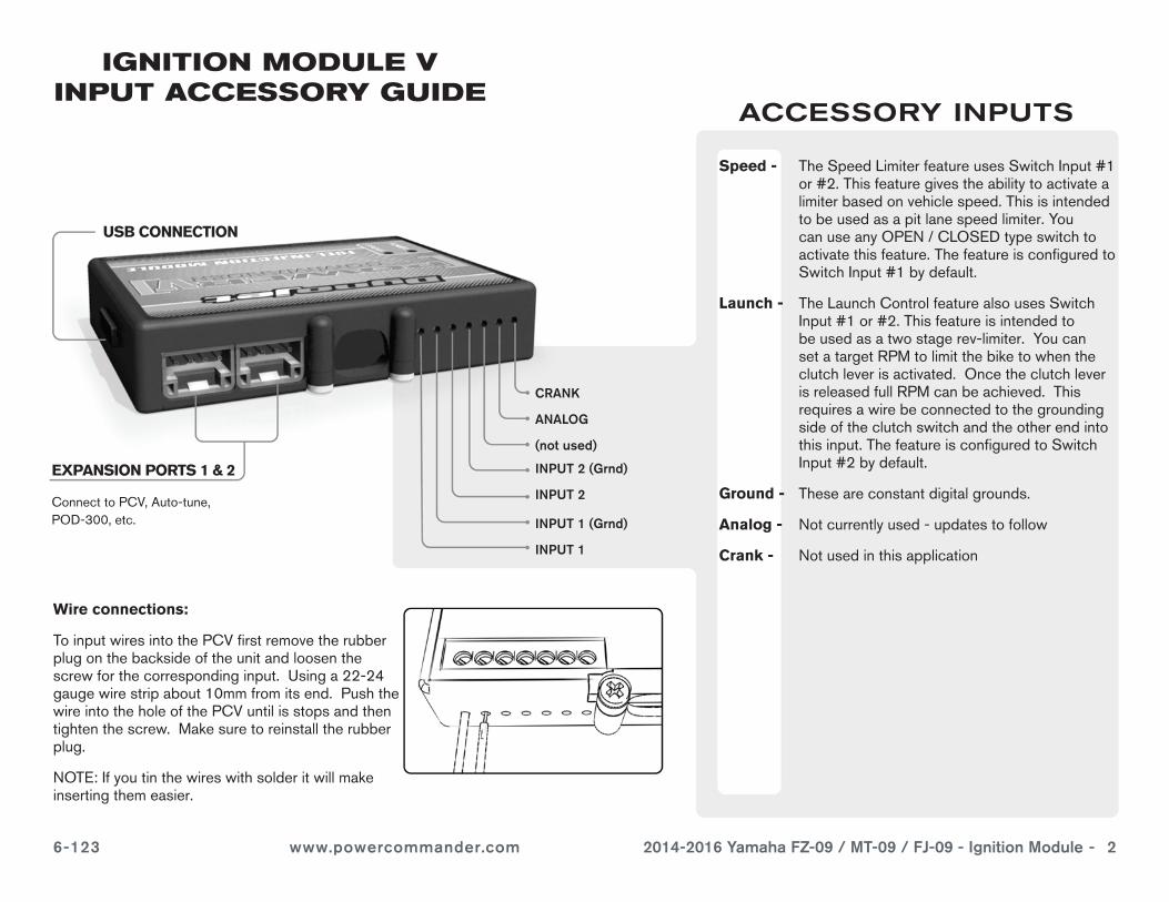
EXPANSION PORTS 1 & 2
Connect to PCV, Auto-tune, POD-300, etc.
IGNITION MODULE V INPUT ACCESSORY GUIDE
Speed - The Speed Limiter feature uses Switch Input #1 or #2. This feature gives the ability to activate a limiter based on vehicle speed. This is intended to be used as a pit lane speed limiter. You can use any OPEN / CLOSED type switch to activate this feature. The feature is configured to Switch Input #1 by default.
Launch - The Launch Control feature also uses Switch Input #1 or #2. This feature is intended to be used as a two stage rev-limiter. You can set a target RPM to limit the bike to when the clutch lever is activated. Once the clutch lever is released full RPM can be achieved. This requires a wire be connected to the grounding side of the clutch switch and the other end into this input. The feature is configured to Switch Input #2 by default.
Ground - These are constant digital grounds.
Analog - Not currently used - updates to follow
Crank - Not used in this application
ACCESSORY INPUTS
Wire connections:
To input wires into the PCV first remove the rubber plug on the backside of the unit and loosen the screw for the corresponding input. Using a 22-24 gauge wire strip about 10mm from its end. Push the wire into the hole of the PCV until is stops and then tighten the screw. Make sure to reinstall the rubber plug.
NOTE: If you tin the wires with solder it will make inserting them easier.
CRANK
ANALOG
(not used)
INPUT 1 (Grnd)
USB CONNECTION
INPUT 1
INPUT 2 (Grnd)
INPUT 2
6-123 www.powercommander.com 2014-2016 Yamaha FZ-09 / MT-09 / FJ-09 - Ignition Module - 3
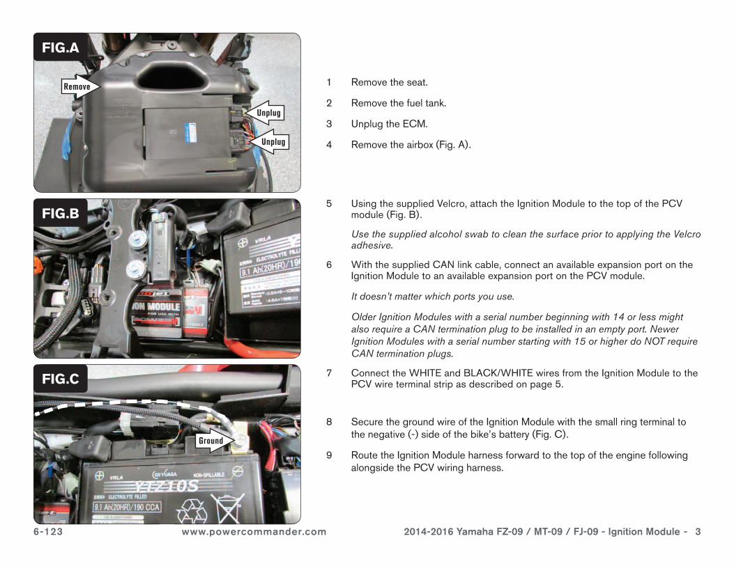
1 Remove the seat.
2 Remove the fuel tank.
3 Unplug the ECM.
4 Remove the airbox (Fig. A).
8 Secure the ground wire of the Ignition Module with the small ring terminal to the negative (-) side of the bike’s battery (Fig. C).
9 Route the Ignition Module harness forward to the top of the engine following alongside the PCV wiring harness.
FIG.A
FIG.C
FIG.B
Unplug
5 Using the supplied Velcro, attach the Ignition Module to the top of the PCV module (Fig. B).
Use the supplied alcohol swab to clean the surface prior to applying the Velcro adhesive.
6 With the supplied CAN link cable, connect an available expansion port on the Ignition Module to an available expansion port on the PCV module.
It doesn’t matter which ports you use.
Older Ignition Modules with a serial number beginning with 14 or less might also require a CAN termination plug to be installed in an empty port. Newer Ignition Modules with a serial number starting with 15 or higher do NOT require CAN termination plugs.
7 Connect the WHITE and BLACK/WHITE wires from the Ignition Module to the PCV wire terminal strip as described on page 5.
Unplug
Remove
Ground
6-123 www.powercommander.com 2014-2016 Yamaha FZ-09 / MT-09 / FJ-09 - Ignition Module - 4
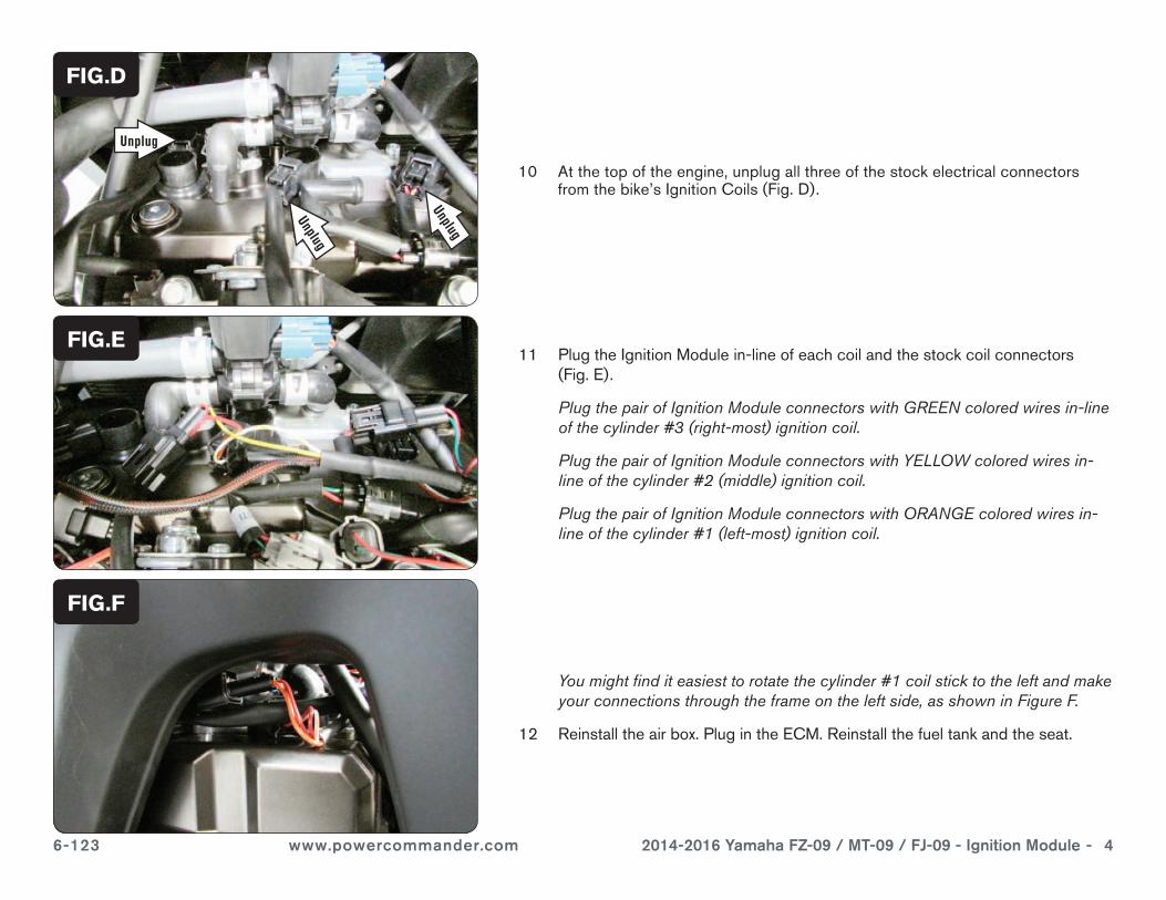
10 At the top of the engine, unplug all three of the stock electrical connectors from the bike’s Ignition Coils (Fig. D).
11 Plug the Ignition Module in-line of each coil and the stock coil connectors (Fig. E).
Plug the pair of Ignition Module connectors with GREEN colored wires in-line of the cylinder #3 (right-most) ignition coil.
Plug the pair of Ignition Module connectors with YELLOW colored wires in-line of the cylinder #2 (middle) ignition coil.
Plug the pair of Ignition Module connectors with ORANGE colored wires in-line of the cylinder #1 (left-most) ignition coil.
FIG.D
FIG.E
You might find it easiest to rotate the cylinder #1 coil stick to the left and make your connections through the frame on the left side, as shown in Figure F.
12 Reinstall the air box. Plug in the ECM. Reinstall the fuel tank and the seat.
FIG.F
Unplug
Unplug
Unplug
6-123 www.powercommander.com 2014-2016 Yamaha FZ-09 / MT-09 / FJ-09 - Ignition Module - 5
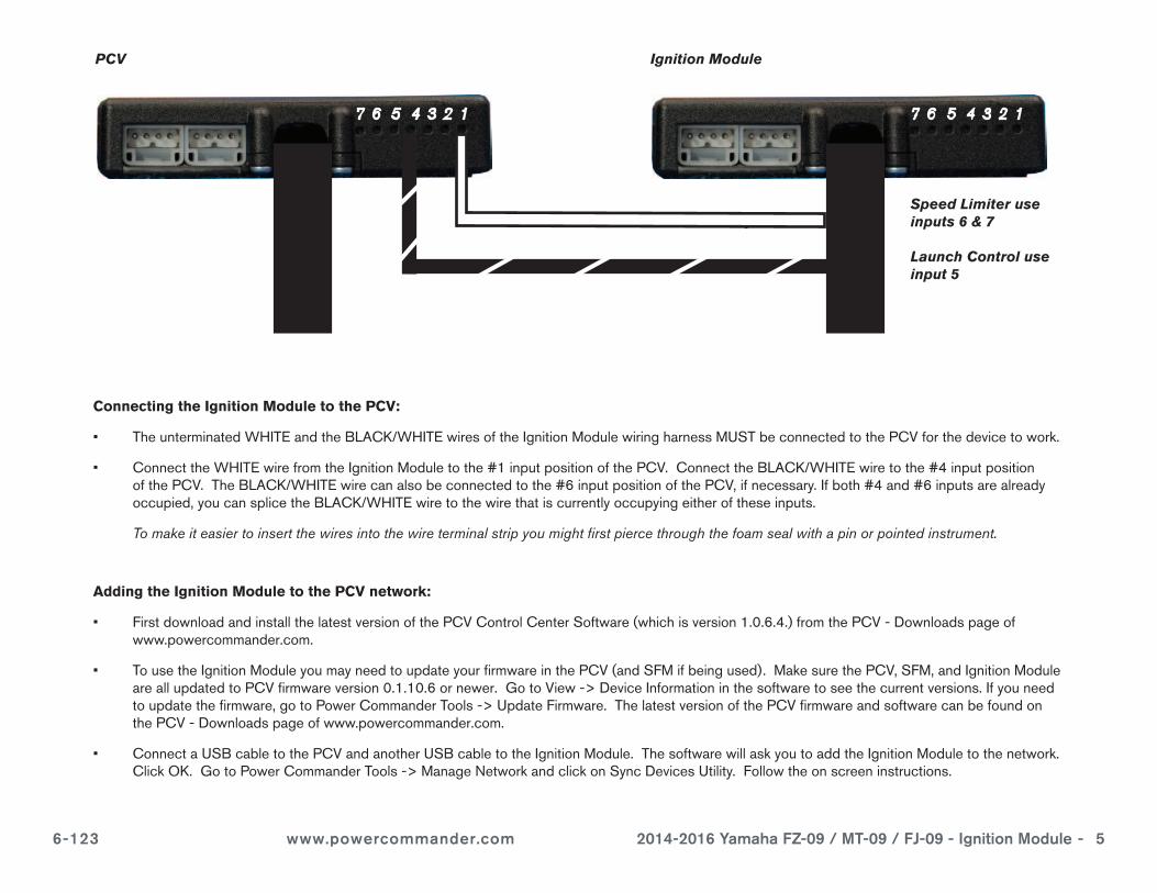
PCV Ignition Module
Speed Limiter use inputs 6 & 7
Launch Control use input 5
Connecting the Ignition Module to the PCV:
• The unterminated WHITE and the BLACK/WHITE wires of the Ignition Module wiring harness MUST be connected to the PCV for the device to work.
• Connect the WHITE wire from the Ignition Module to the #1 input position of the PCV. Connect the BLACK/WHITE wire to the #4 input position of the PCV. The BLACK/WHITE wire can also be connected to the #6 input position of the PCV, if necessary. If both #4 and #6 inputs are already occupied, you can splice the BLACK/WHITE wire to the wire that is currently occupying either of these inputs.
To make it easier to insert the wires into the wire terminal strip you might first pierce through the foam seal with a pin or pointed instrument.
Adding the Ignition Module to the PCV network:
• First download and install the latest version of the PCV Control Center Software (which is version 1.0.6.4.) from the PCV - Downloads page of www.powercommander.com.
• To use the Ignition Module you may need to update your firmware in the PCV (and SFM if being used). Make sure the PCV, SFM, and Ignition Module are all updated to PCV firmware version 0.1.10.6 or newer. Go to View -> Device Information in the software to see the current versions. If you need to update the firmware, go to Power Commander Tools -> Update Firmware. The latest version of the PCV firmware and software can be found on the PCV - Downloads page of www.powercommander.com.
• Connect a USB cable to the PCV and another USB cable to the Ignition Module. The software will ask you to add the Ignition Module to the network. Click OK. Go to Power Commander Tools -> Manage Network and click on Sync Devices Utility. Follow the on screen instructions.