Embed Size (px)
Citation preview

500 S. 500 W.Building 1Lindon, UT 84042801.805.6657
HeadquartersBiggen 5D-57439 AttendornPhone: +49[0]2722 950-0www.aquatherm.de
NSF®
Edition 03/14 Printed in the USA
P
ipe
S y s te m
s
M
ADE IN GERMA
NY
© 2014 GmbH, NA, L.c., and CA.All rights reserved.
2014A
quatherm Piping System
s

As we have grown from one man working out of his home garage in Germany forty years ago to the world’s largest and most advanced PP-R pressure pipe manufacturer, Aquatherm has found success through constant improvement and by adapting to customer’s needs.
Aquatherm’s products were first introduced to the North American market in 2005 and have been widely used in a variety of projects since.
We stand by the philosophy that a better product is better for everyone, including our planet.
This catalog provides an introduction to our products and services as well as detailed design and engineering information.
Please contact us with any questions or comments you have regarding our piping systems.
WE MAKE THE BEST POLYPROPYLENE PRESSURE PIPING SYSTEMS IN THE WORLD. PERIOD.
1973 Aquatherm founded by Gerhard Rosenberg
1978 Transfer to the first factory in Attendorn, Germany
1985Factory 1 in Attendorn, Germany completed
1996 Founding of the metal processing company, Aquatherm Metal, in Attendorn
1999Main campus in Attendorn completed as one complex (factories 1+2, storage, assembly, laboratory and training center)
2002 Logistics center in Attendorn completed
2005Aquatherm launched in Canada
2007Aquatherm launched in the United States
2012Aquatherm North American logistics center established in Lindon, Utah
WELCOME TO AQUATHERM
Aquatherm NA Managing Directors (from left) Jordan Hardy (CFO), Adam Clark (President and COO) and David Chen (CEO).
Aquatherm GmbH founder Gerhard Rosenberg (middle left) and his sons (from left), Managing Directors Maik, Cristof, and Dirk.
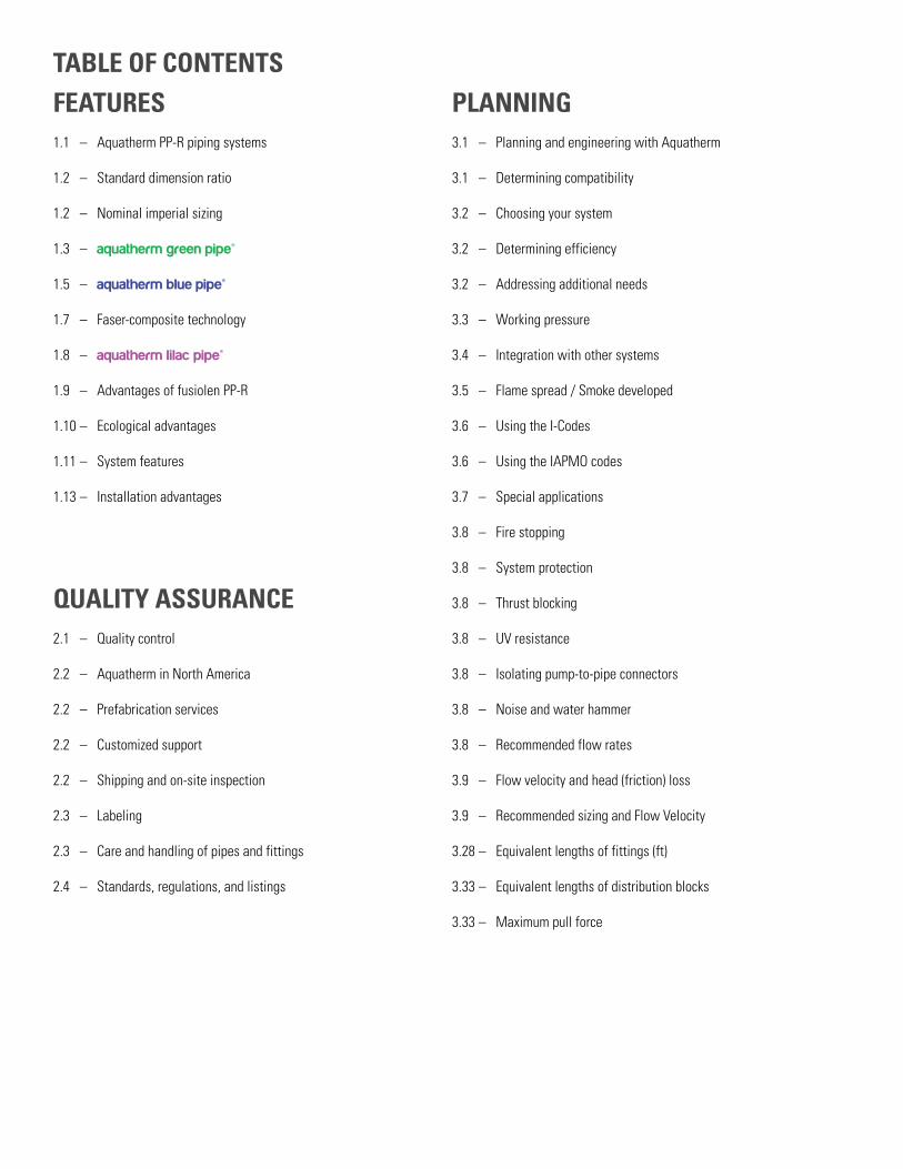
TABLE OF CONTENTSFEATURES1.1 – Aquatherm PP-R piping systems
1.2 – Standard dimension ratio
1.2 – Nominal imperial sizing
1.3 – aquatherm green pipe®
1.5 – aquatherm blue pipe®
1.7 – Faser-composite technology
1.8 – aquatherm lilac pipe®
1.9 – Advantages of fusiolen PP-R
1.10 – Ecological advantages
1.11 – System features
1.13 – Installation advantages
QUALITY ASSURANCE2.1 – Quality control
2.2 – Aquatherm in North America
2.2 – Prefabrication services
2.2 – Customized support
2.2 – Shipping and on-site inspection
2.3 – Labeling
2.3 – Care and handling of pipes and fittings
2.4 – Standards, regulations, and listings
PLANNING3.1 – Planning and engineering with Aquatherm
3.1 – Determining compatibility
3.2 – Choosing your system
3.2 – Determining efficiency
3.2 – Addressing additional needs
3.3 – Working pressure
3.4 – Integration with other systems
3.5 – Flame spread / Smoke developed
3.6 – Using the I-Codes
3.6 – Using the IAPMO codes
3.7 – Special applications
3.8 – Fire stopping
3.8 – System protection
3.8 – Thrust blocking
3.8 – UV resistance
3.8 – Isolating pump-to-pipe connectors
3.8 – Noise and water hammer
3.8 – Recommended flow rates
3.9 – Flow velocity and head (friction) loss
3.9 – Recommended sizing and Flow Velocity
3.28 – Equivalent lengths of fittings (ft)
3.33 – Equivalent lengths of distribution blocks
3.33 – Maximum pull force

Note: This version of the Aquatherm catalog has been modified for distribution in Canada and the United States by Aquatherm NA, L.C. The text has been translated and edited for greater clarity and the data has been converted from metric to imperial units. Some content has been added to address issues specific to North America. As such, Aquatherm GmbH assumes no responsibility for these modifications, and assumes no liability for any problems that may arise from them. In addition, Aquatherm NA, L.C. does not warranty the accuracy, reliability or completeness of any information contained herein. In the case of discrepancies between this document and any information published or produced by Aquatherm GmbH, the material published by Aquatherm GmbH shall be considered the authoritative source. This edition supersedes all previous editions of the Aquatherm catalog, and will be replaced by the next edition.
INSTALLATION PRINCIPLES4.1 – Heat fusion connections
4.2 – Training and installation
4.3 – Socket fusion
4.3 – Mechanically assisted fusions
4.3 – Butt fusion
4.3 – Outlet fusion
4.3 – Electrofusion
4.4 – Planning
4.5 – Supporting the pipe
4.7 – Linear expansion
4.11 – Expansion controls
4.15 – Fusion outlets
4.16 – Transition fittings
4.17 – Aquatherm distribution blocks
4.19 – Flushing the pipes
4.19 – UV protection
4.19 – Freeze protection
4.19 – Grounding
4.19 – Transport and storage
4.20 – Pressure test
PRODUCT RANGE5.1 – aquatherm green pipe® SDR 7.4 MF
5.2 – aquatherm green pipe® SDR 7.4/11 S
5.3 – aquatherm green pipe® SDR 7.4 MF UV
5.4 – aquatherm blue pipe® SDR 7.4/11 MF
5.5 – aquatherm blue pipe® SDR 17.6 MF
5.6 – aquatherm blue pipe® SDR 7.4/11 MF UV
5.8 – aquatherm lilac pipe® SDR 7.4/11 S
5.9 – Accessories
5.10 – Fittings
5.31 – Flanges
5.33 – Couplings
5.35 – PP-R to metal
5.44 – Distributors
5.45 – Valves
5.50 – Tools


FEATURES
FEAT
URE
S
Chapter
1
Aquatherm pipe systems
Standard dimension ratio
aquatherm green pipe®
aquatherm blue pipe®
Multilayer faser technology
aquatherm lilac pipe®
fusiolen® PP-R
Ecological advantages
System features
Installation advantages
FEATURES1
1.1
FEATURES
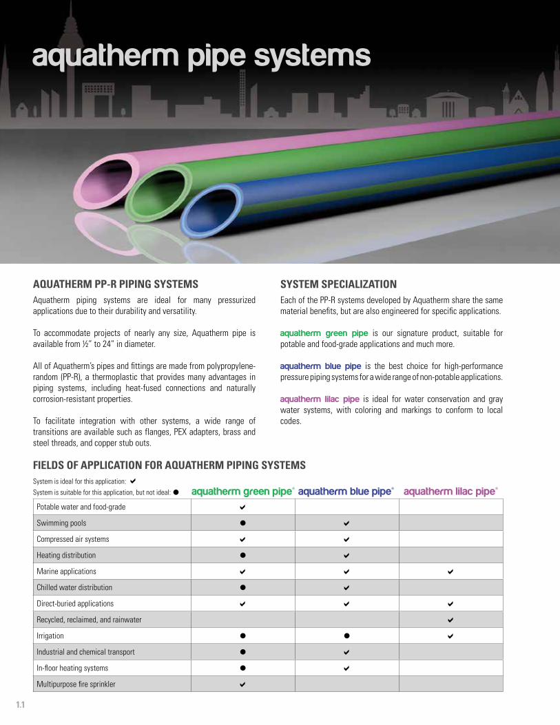
FIELDS OF APPLICATION FOR AQUATHERM PIPING SYSTEMSSystem is ideal for this application: System is suitable for this application, but not ideal: l aquatherm green pipe® aquatherm blue pipe® aquatherm lilac pipe®
Potable water and food-grade
Swimming pools l
Compressed air systems
Heating distribution l
Marine applications
Chilled water distribution l
Direct-buried applications
Recycled, reclaimed, and rainwater
Irrigation l l
Industrial and chemical transport l
In-floor heating systems l
Multipurpose fire sprinkler
aquatherm pipe systems
SYSTEM SPECIALIZATIONEach of the PP-R systems developed by Aquatherm share the same material benefits, but are also engineered for specific applications.
aquatherm green pipe is our signature product, suitable for potable and food-grade applications and much more.
aquatherm blue pipe is the best choice for high-performance pressure piping systems for a wide range of non-potable applications.
aquatherm lilac pipe is ideal for water conservation and gray water systems, with coloring and markings to conform to local codes.
AQUATHERM PP-R PIPING SYSTEMSAquatherm piping systems are ideal for many pressurized applications due to their durability and versatility.
To accommodate projects of nearly any size, Aquatherm pipe is available from ½” to 24” in diameter.
All of Aquatherm’s pipes and fittings are made from polypropylene-random (PP-R), a thermoplastic that provides many advantages in piping systems, including heat-fused connections and naturally corrosion-resistant properties.
To facilitate integration with other systems, a wide range of transitions are available such as flanges, PEX adapters, brass and steel threads, and copper stub outs.
1.2
FEATURES
NOMINAL IMPERIAL SIZINGAll Aquatherm piping systems are manufactured in metric sizes. In order to make the systems more intuitive to the North American market, Aquatherm has converted each of its standard pipe sizes into an imperial nominal diameter based on comparable size and flow rate.
The below tables give a standard nominal diameter for each metric size of pipe. Use the flow rate tables given in chapter 3 to verify proper selection for an application based on SDR and flow rate. The metric outside diameter (OD) is printed on the pipe and fitting bags in addition to the nominal diameter.
Actualmetric OD
Nominal diameter
20 mm ½”
25 mm ¾”
32 mm 1”
40 mm 1 ¼”
50 mm 1 ½”
63 mm 2”
75 mm 2 ½”
90 mm 3”
110 mm 3 ½”
125 mm 4”
Actualmetric OD
Nominal diameter
160 mm 6”
200 mm 8”
250 mm 10”
315 mm 12”
355 mm 14”
400 mm 16”
450 mm 18”
500 mm 20”
560 mm 22”
630 mm 24”
Nominal diameter
SDR 7.4 SDR 11 SDR 17.6
½” 0.013 0.017 -
¾” 0.024 0.026 -
1” 0.034 0.043 -
1 ¼” 0.053 0.067 -
1 ½” 0.083 0.105 -
2” 0.133 0.167 -
2 ½” 0.187 0.237 -
3” 0.270 0.343 -
3 ½” 0.402 0.512 -
4” 0.521 0.661 0.776
6” 0.854 1.082 1.272
8” 1.333 1.692 1.986
10” 2.084 2.646 3.105
12” 3.340 4.201 4.930
14” 4.242 5.340 6.267
16” - 6.787 7.952
18” - 8.573 10.068
20” - - 12.422
22” - - 15.596
24” - - 19.733
COMPARISON OF WATER CAPACITY (GAL/FT)
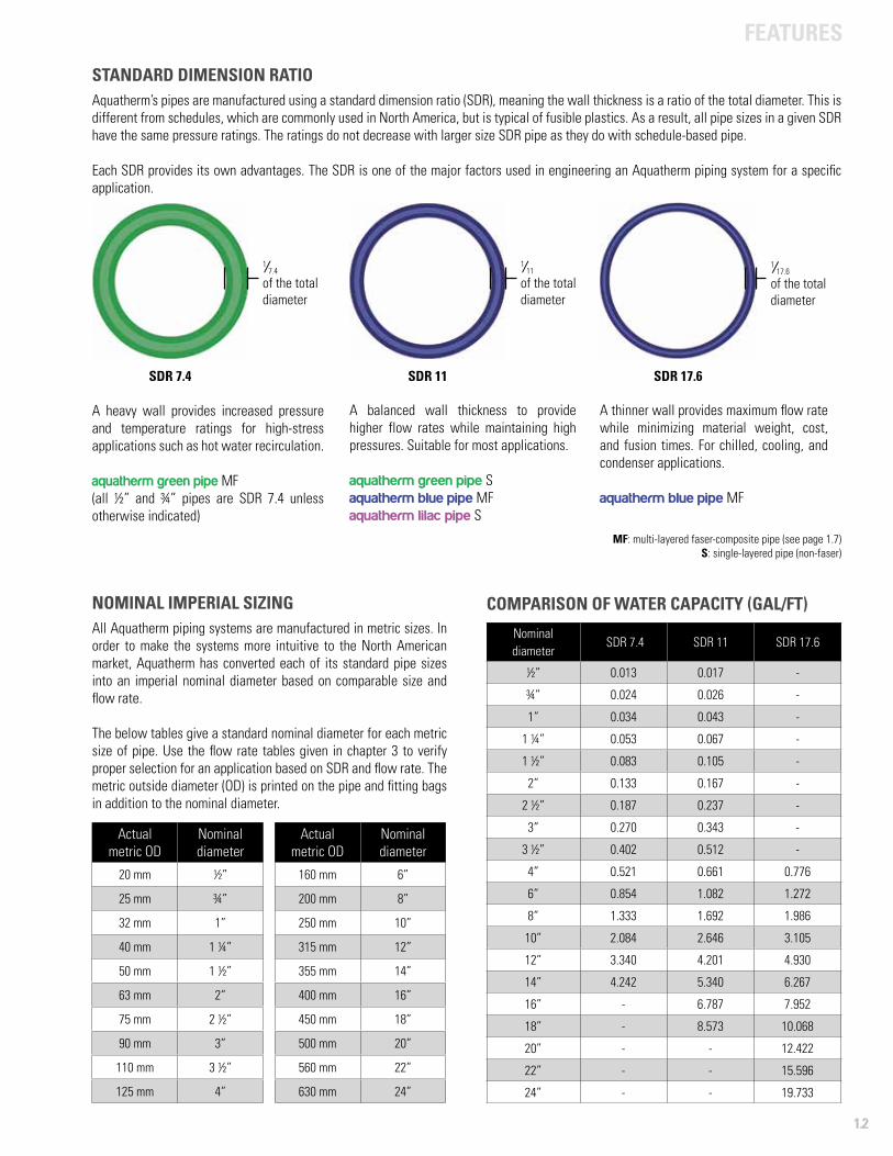
STANDARD DIMENSION RATIO Aquatherm’s pipes are manufactured using a standard dimension ratio (SDR), meaning the wall thickness is a ratio of the total diameter. This is different from schedules, which are commonly used in North America, but is typical of fusible plastics. As a result, all pipe sizes in a given SDR have the same pressure ratings. The ratings do not decrease with larger size SDR pipe as they do with schedule-based pipe.
Each SDR provides its own advantages. The SDR is one of the major factors used in engineering an Aquatherm piping system for a specific application.
SDR 7.4
1/ 7.4 of the total diameter
SDR 11
1/ 11
of the total diameter
SDR 17.6
1/ 17.6
of the total diameter
A heavy wall provides increased pressure and temperature ratings for high-stress applications such as hot water recirculation.
aquatherm green pipe MF(all ½” and ¾” pipes are SDR 7.4 unless otherwise indicated)
A balanced wall thickness to provide higher flow rates while maintaining high pressures. Suitable for most applications.
aquatherm green pipe Saquatherm blue pipe MFaquatherm lilac pipe S
A thinner wall provides maximum flow rate while minimizing material weight, cost, and fusion times. For chilled, cooling, and condenser applications.
aquatherm blue pipe MF
MF: multi-layered faser-composite pipe (see page 1.7)S: single-layered pipe (non-faser)

1.3
FEATURES
THE ULTIMATE IN POTABLE WATER PIPING TECHNOLOGYaquatherm green pipe is a pressure piping system with a wide range of applications. Exceptional chemical purity and outstanding physical strength have made aquatherm green pipe successful in over 70 countries worldwide.
aquatherm green pipe can be used in almost every aspect of the piping industry, but is best suited for potable and food-grade applications, where the combination of chemical safety and physical durability can truly perform. aquatherm green pipe can be used for multipurpose residential sprinkler applications per NFPA 13D.
With over 400 fittings, transitions, and valves, aquatherm green pipe easily fits into any design or space. The dimensions range from ½” to 18” nominal diameter (ND). aquatherm green pipe is also available with UV protection for outdoor installations and multi-layer faser-composite (MF) technology, which reduces linear expansion.
NON-LEACHING COMPOSITIONPP-R is a hydrophobic material, meaning it repels polarized molecules like H2O and makes aquatherm green pipe the perfect fit for potable systems.
Using a material that does not interact with water or most other fluids ensures that chemicals from the pipe walls and fittings will never leach into drinking water or the underground water table. This makes the pipe healthier for the people who use it and safer for the environment they live in.
ADVANTAGES• Leak-free connections• Resistant to hard water and aggressive chemicals• Does not leach, corrode or erode• Environmentally friendly material• Natural sound and heat insulation• Excellent flow rate• Potable water (NSF 61) and food rated (NSF 51)• Fast and easy assembly• Suitable for direct-buried and trenchless applications• Flame, smoke, and fume-free installation• Dampens water hammer and vibration and decreases noise
Sample specifications for aquatherm green pipe can be found at www.aquatherm.com/specifications-and-submittals.
aquatherm green pipe®As our signature PP-R pipe, Green Pipe is the
SAFEST, MOST RELIABLE CHOICE FOR POTABLE APPLICATIONSand many other projects.
Fields of application
1.4
FEATURES
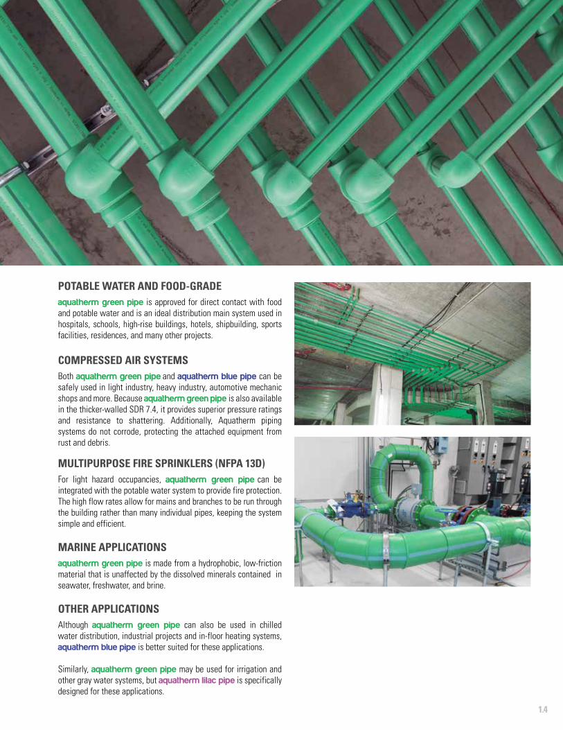
POTABLE WATER AND FOOD-GRADE aquatherm green pipe is approved for direct contact with food and potable water and is an ideal distribution main system used in hospitals, schools, high-rise buildings, hotels, shipbuilding, sports facilities, residences, and many other projects.
COMPRESSED AIR SYSTEMSBoth aquatherm green pipe and aquatherm blue pipe can be safely used in light industry, heavy industry, automotive mechanic shops and more. Because aquatherm green pipe is also available in the thicker-walled SDR 7.4, it provides superior pressure ratings and resistance to shattering. Additionally, Aquatherm piping systems do not corrode, protecting the attached equipment from rust and debris.
MULTIPURPOSE FIRE SPRINKLERS (NFPA 13D)For light hazard occupancies, aquatherm green pipe can be integrated with the potable water system to provide fire protection. The high flow rates allow for mains and branches to be run through the building rather than many individual pipes, keeping the system simple and efficient.
MARINE APPLICATIONSaquatherm green pipe is made from a hydrophobic, low-friction material that is unaffected by the dissolved minerals contained in seawater, freshwater, and brine.
OTHER APPLICATIONSAlthough aquatherm green pipe can also be used in chilled water distribution, industrial projects and in-floor heating systems, aquatherm blue pipe is better suited for these applications.
Similarly, aquatherm green pipe may be used for irrigation and other gray water systems, but aquatherm lilac pipe is specifically designed for these applications.
1.5
FEATURES
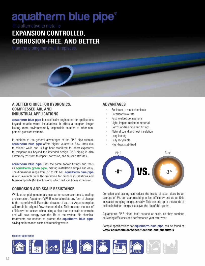
A BETTER CHOICE FOR HYDRONICS, COMPRESSED AIR, AND INDUSTRIAL APPLICATIONSaquatherm blue pipe is specifically engineered for applications beyond potable water installations. It offers a tougher, longer lasting, more environmentally responsible solution to other non-potable pressure systems.
In addition to the general advantages of the PP-R pipe system, aquatherm blue pipe offers higher volumetric flow rates due to thinner walls and is high-heat stabilized for short exposures to temperatures beyond the intended design. PP-R piping is also extremely resistant to impact, corrosion, and seismic stresses.
aquatherm blue pipe uses the same socket fittings and tools as aquatherm green pipe, making installation simple and easy. The dimensions range from ½” to 24” ND. aquatherm blue pipe is also available with UV protection for outdoor installations and faser-composite (MF) technology, which reduces linear expansion.
CORROSION AND SCALE RESISTANCEWhile other piping materials lose performance over time to scaling and corrosion, Aquatherm’s PP-R material resists any form of change to the material wall. Even after decades of use, the Aquatherm pipe will retain its original flow characteristics. This prevents the loss of efficiency that occurs when using a pipe that can scale or corrode and will save energy over the life of the system. No chemical treatments are needed to protect the aquatherm blue pipe, saving maintenance costs and reducing waste.
ADVANTAGES• Resistant to most chemicals• Excellent flow rate• Fast, welded connections• Light, impact-resistant material• Corrosion-free pipe and fittings• Natural sound and heat insulation• Long lasting • Fully recyclable• High-heat stabilized
aquatherm blue pipe®This alternative to metal is
EXPANSION CONTROLLED, CORROSION-FREE, AND BETTERthan the piping material it replaces.
SteelPP-R
-0% -3%
Corrosion and scaling can reduce the inside of steel pipes by an average of 3% per year, resulting in lost efficiency and up to 10% increased pumping energy annually. This can add up to thousands of dollars in hidden energy costs over the life of the system.
Aquatherm’s PP-R pipes don’t corrode or scale, so they continue delivering efficiency and performance year after year.
Sample specifications for aquatherm blue pipe can be found at www.aquatherm.com/specifications-and-submittals.
Fields of application
+F°
1.6
FEATURES
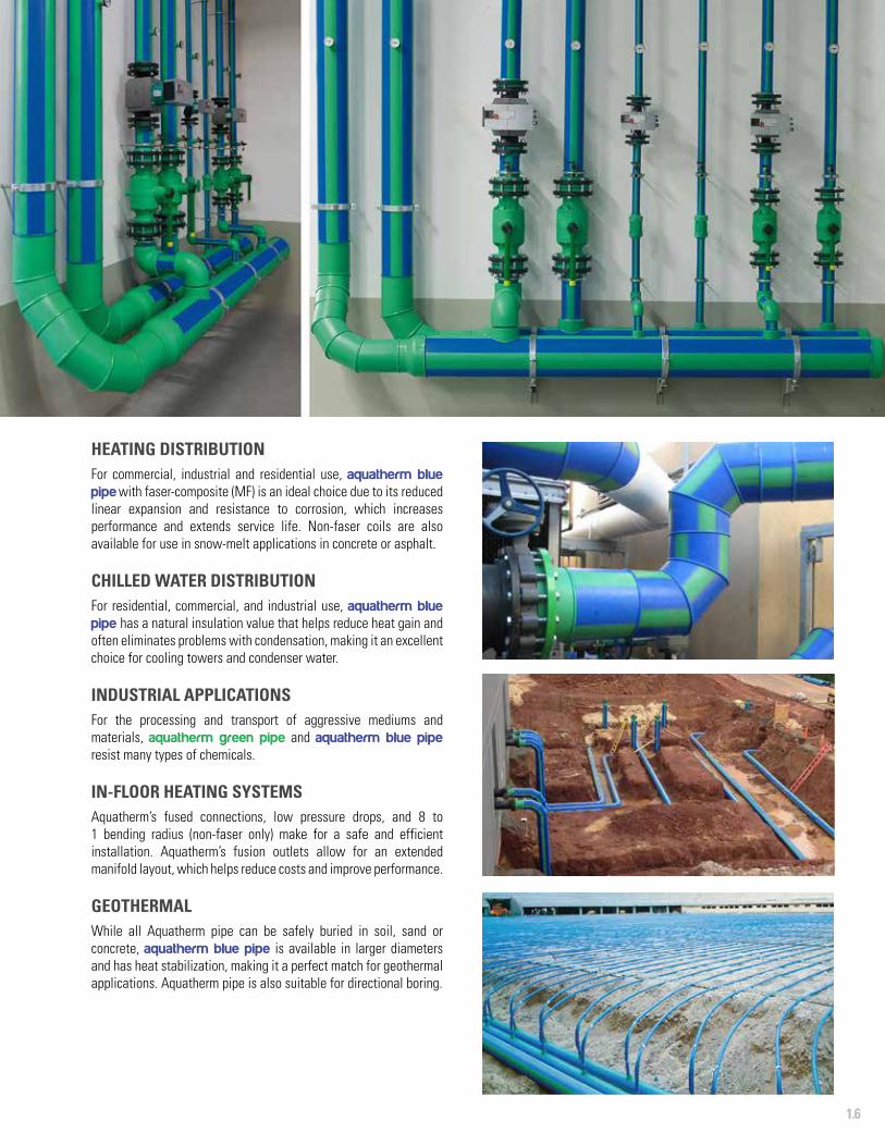
HEATING DISTRIBUTIONFor commercial, industrial and residential use, aquatherm blue pipe with faser-composite (MF) is an ideal choice due to its reduced linear expansion and resistance to corrosion, which increases performance and extends service life. Non-faser coils are also available for use in snow-melt applications in concrete or asphalt.
CHILLED WATER DISTRIBUTIONFor residential, commercial, and industrial use, aquatherm blue pipe has a natural insulation value that helps reduce heat gain and often eliminates problems with condensation, making it an excellent choice for cooling towers and condenser water.
INDUSTRIAL APPLICATIONSFor the processing and transport of aggressive mediums and materials, aquatherm green pipe and aquatherm blue pipe resist many types of chemicals.
IN-FLOOR HEATING SYSTEMS Aquatherm’s fused connections, low pressure drops, and 8 to 1 bending radius (non-faser only) make for a safe and efficient installation. Aquatherm’s fusion outlets allow for an extended manifold layout, which helps reduce costs and improve performance.
GEOTHERMALWhile all Aquatherm pipe can be safely buried in soil, sand or concrete, aquatherm blue pipe is available in larger diameters and has heat stabilization, making it a perfect match for geothermal applications. Aquatherm pipe is also suitable for directional boring.
1.7
FEATURES
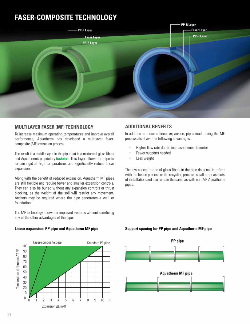
MULTILAYER FASER (MF) TECHNOLOGYTo increase maximum operating temperatures and improve overall performance, Aquatherm has developed a multilayer faser-composite (MF) extrusion process.
The result is a middle layer in the pipe that is a mixture of glass fibers and Aquatherm’s proprietary fusiolen. This layer allows the pipe to remain rigid at high temperatures and significantly reduce linear expansion.
Along with the benefit of reduced expansion, Aquatherm MF pipes are still flexible and require fewer and smaller expansion controls. They can also be buried without any expansion controls or thrust blocking, as the weight of the soil will restrict any movement. Anchors may be required where the pipe penetrates a wall or foundation.
The MF technology allows for improved systems without sacrificing any of the other advantages of the pipe.
Support spacing for PP pipe and Aquatherm MF pipe
Faser Layer
FASER-COMPOSITE TECHNOLOGYPP-R Layer
PP-R LayerFaser Layer
PP-R Layer
PP-R Layer
ADDITIONAL BENEFITSIn addition to reduced linear expansion, pipes made using the MF process also have the following advantages:
• Higher flow rate due to increased inner diameter • Fewer supports needed• Less weight
The low concentration of glass fibers in the pipe does not interfere with the fusion process or the recycling process, so all other aspects of installation and use remain the same as with non-MF Aquatherm pipes.
Linear expansion: PP pipe and Aquatherm MF pipe
PP pipe
Aquatherm MF pipe
0 1 2 3 4 5 6 7 8 9 10 110102030405060708090
100
Tem
pera
ture
diff
eren
ce ∆
T °F
Expansion ∆L in/ft
Faser-composite pipe Standard PP pipe
1.8
FEATURES
aquatherm lilac pipe®
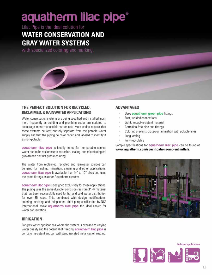
THE PERFECT SOLUTION FOR RECYCLED, RECLAIMED, & RAINWATER APPLICATIONSWater conservation systems are being specified and installed much more frequently as building and plumbing codes are updated to encourage more responsible water use. Most codes require that these systems be kept entirely separate from the potable water supply and that the piping be color coded and labeled to identify it as non-potable.
aquatherm lilac pipe is ideally suited for non-potable service water due to its resistance to corrosion, scaling, and microbiological growth and distinct purple coloring.
The water from reclaimed, recycled and rainwater sources can be used for flushing, irrigation, cleaning and other applications. aquatherm lilac pipe is available from ½” to 10” sizes and uses the same fittings as other Aquatherm systems.
aquatherm lilac pipe is designed exclusively for these applications. The piping uses the same durable, corrosion-resistant PP-R material that has been successfully used for hot and cold water distribution for over 35 years. This, combined with design modifications, coloring, marking, and independent third-party certification by NSF International, make aquatherm lilac pipe the ideal choice for water conservation.
IRRIGATIONFor gray water applications where the system is exposed to varying water quality and the potential of freezing, aquatherm lilac pipe is corrosion resistant and can withstand isolated instances of freezing.
Lilac Pipe is the ideal solution for
WATER CONSERVATION AND GRAY WATER SYSTEMS with specialized coloring and marking.
ADVANTAGES• Uses aquatherm green pipe fittings• Fast, welded connections• Light, impact-resistant material• Corrosion-free pipe and fittings• Coloring prevents cross-contamination with potable lines• Long lasting • Fully recyclable
Sample specifications for aquatherm lilac pipe can be found at www.aquatherm.com/specifications-and-submittals.
Fields of application
1.9
FEATURES
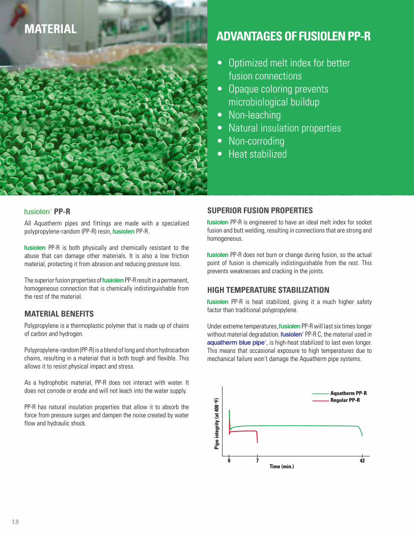
fusiolen® PP-RAll Aquatherm pipes and fittings are made with a specialized polypropylene-random (PP-R) resin, fusiolen PP-R.
fusiolen PP-R is both physically and chemically resistant to the abuse that can damage other materials. It is also a low friction material, protecting it from abrasion and reducing pressure loss.
The superior fusion properties of fusiolen PP-R result in a permanent, homogeneous connection that is chemically indistinguishable from the rest of the material.
MATERIAL BENEFITSPolypropylene is a thermoplastic polymer that is made up of chains of carbon and hydrogen.
Polypropylene-random (PP-R) is a blend of long and short hydrocarbon chains, resulting in a material that is both tough and flexible. This allows it to resist physical impact and stress.
As a hydrophobic material, PP-R does not interact with water. It does not corrode or erode and will not leach into the water supply.
PP-R has natural insulation properties that allow it to absorb the force from pressure surges and dampen the noise created by water flow and hydraulic shock.
Raw fusiolen PP-R granules.
Time (min.)420
Aquatherm PP-R
Pipe
inte
grity
(at 4
00 o F) Regular PP-R
7
MATERIAL
SUPERIOR FUSION PROPERTIESfusiolen PP-R is engineered to have an ideal melt index for socket fusion and butt welding, resulting in connections that are strong and homogeneous.
fusiolen PP-R does not burn or change during fusion, so the actual point of fusion is chemically indistinguishable from the rest. This prevents weaknesses and cracking in the joints.
HIGH TEMPERATURE STABILIZATION fusiolen PP-R is heat stabilized, giving it a much higher safety factor than traditional polypropylene.
Under extreme temperatures, fusiolen PP-R will last six times longer without material degradation. fusiolen® PP-R C, the material used in aquatherm blue pipe®, is high-heat stabilized to last even longer. This means that occasional exposure to high temperatures due to mechanical failure won’t damage the Aquatherm pipe systems.
ADVANTAGES OF FUSIOLEN PP-R
• Optimized melt index for better fusion connections
• Opaque coloring prevents microbiological buildup
• Non-leaching• Natural insulation properties• Non-corroding• Heat stabilized
1.10
FEATURES
ENVIRONMENTAL SAFETYSince its founding in 1973, Aquatherm has worked hard to ensure that our products and manufacturing processes do not pollute the earth’s sensitive ecosystems. Being green isn’t just a fad with Aquatherm; it’s our way of doing business.
Aquatherm believes that ecological and economic interests should go hand-in-hand, both in the production and installation of our products. Aquatherm’s PP-R pipes and fittings are even fully recyclable, minimizing their impact from start to finish.
To ensure its environmental compatibility, the base PP-R material and additives (color pigments and stabilizers) are extensively tested by Aquatherm’s own laboratory as well as independent researchers to ensure that nothing harmful is ever put into our pipes.
AQUATHERM AND LEED CREDITSAquatherm pipe has been used in many LEED certified projects. Although there are no direct LEED credits for using a particular piping material, there are several points which the right piping system can address.
Please refer to the Aquatherm LEED Planning Guide on our website at www.aquatherm.com/technical-documents for further details. Information regarding LEED projects that have used Aquatherm pipes can be found in the Case Studies section.
EXTENDED SERVICE LIFEAquatherm pipes will last for over 60 years within the design parameters provided in this catalog. This eliminates the environmental impact of repairs, mold, leaks, and other problems caused by piping failure.
By using components that last longer, buildings can be made safer and more sustainable.
ECOLOGICAL ADVANTAGES
• Improved efficiency• No toxic materials such as PVC, BPAs,
dioxins, phthalates or VOCs• Fully recyclable pipe and fittings• Extended service life• Free of heavy metals• Chemically inert• Emission-free installation
HIGH-OPACITY PIGMENTATIONfusiolen PP-R is intentionally pigmented to be opaque, preventing light from entering the pipe. This helps protect the pipe from microbiological build-up and increases the service life of the system.
LOW-IMPACT LIFECYCLEfusiolen PP-R is fully recyclable and can be ground, melted, and re-used in car parts, home products, food packaging, medical equipment, and other applications.
There are no harmful waste products created by the processing or disposal of fusiolen PP-R. The pipe and fittings made with fusiolen PP-R have an estimated service life of over 60 years. As a result, Aquatherm’s pipe systems rarely require maintenance or costly repairs.
PROVEN WORLDWIDEAquatherm piping systems have been tested, listed, and certified by numerous national and international organizations, including:
• NSF, ICC, IAPMO, ASTM, FM, BNQ, CFIA (North America)• DVGW, SKZ (Germany)• WRAS (UK)• SVGW (Switzerland)• SAI-Global (Australia)• SITAC (Sweden) … and many more!
1.11
FEATURES
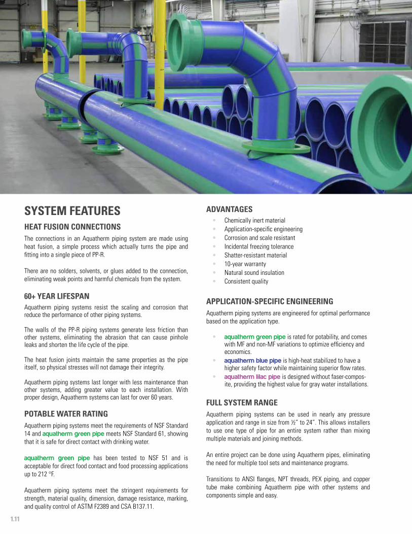
SYSTEM FEATURES
HEAT FUSION CONNECTIONSThe connections in an Aquatherm piping system are made using heat fusion, a simple process which actually turns the pipe and fitting into a single piece of PP-R.
There are no solders, solvents, or glues added to the connection, eliminating weak points and harmful chemicals from the system.
60+ YEAR LIFESPANAquatherm piping systems resist the scaling and corrosion that reduce the performance of other piping systems.
The walls of the PP-R piping systems generate less friction than other systems, eliminating the abrasion that can cause pinhole leaks and shorten the life cycle of the pipe.
The heat fusion joints maintain the same properties as the pipe itself, so physical stresses will not damage their integrity.
Aquatherm piping systems last longer with less maintenance than other systems, adding greater value to each installation. With proper design, Aquatherm systems can last for over 60 years.
POTABLE WATER RATINGAquatherm piping systems meet the requirements of NSF Standard 14 and aquatherm green pipe meets NSF Standard 61, showing that it is safe for direct contact with drinking water.
aquatherm green pipe has been tested to NSF 51 and is acceptable for direct food contact and food processing applications up to 212 °F.
Aquatherm piping systems meet the stringent requirements for strength, material quality, dimension, damage resistance, marking, and quality control of ASTM F2389 and CSA B137.11.
ADVANTAGES• Chemically inert material• Application-specific engineering• Corrosion and scale resistant• Incidental freezing tolerance• Shatter-resistant material • 10-year warranty• Natural sound insulation• Consistent quality
APPLICATION-SPECIFIC ENGINEERINGAquatherm piping systems are engineered for optimal performance based on the application type.
• aquatherm green pipe is rated for potability, and comes with MF and non-MF variations to optimize efficiency and economics.
• aquatherm blue pipe is high-heat stabilized to have a higher safety factor while maintaining superior flow rates.
• aquatherm lilac pipe is designed without faser-compos-ite, providing the highest value for gray water installations.
FULL SYSTEM RANGEAquatherm piping systems can be used in nearly any pressure application and range in size from ½” to 24”. This allows installers to use one type of pipe for an entire system rather than mixing multiple materials and joining methods.
An entire project can be done using Aquatherm pipes, eliminating the need for multiple tool sets and maintenance programs.
Transitions to ANSI flanges, NPT threads, PEX piping, and copper tube make combining Aquatherm pipe with other systems and components simple and easy.
1.12
FEATURES
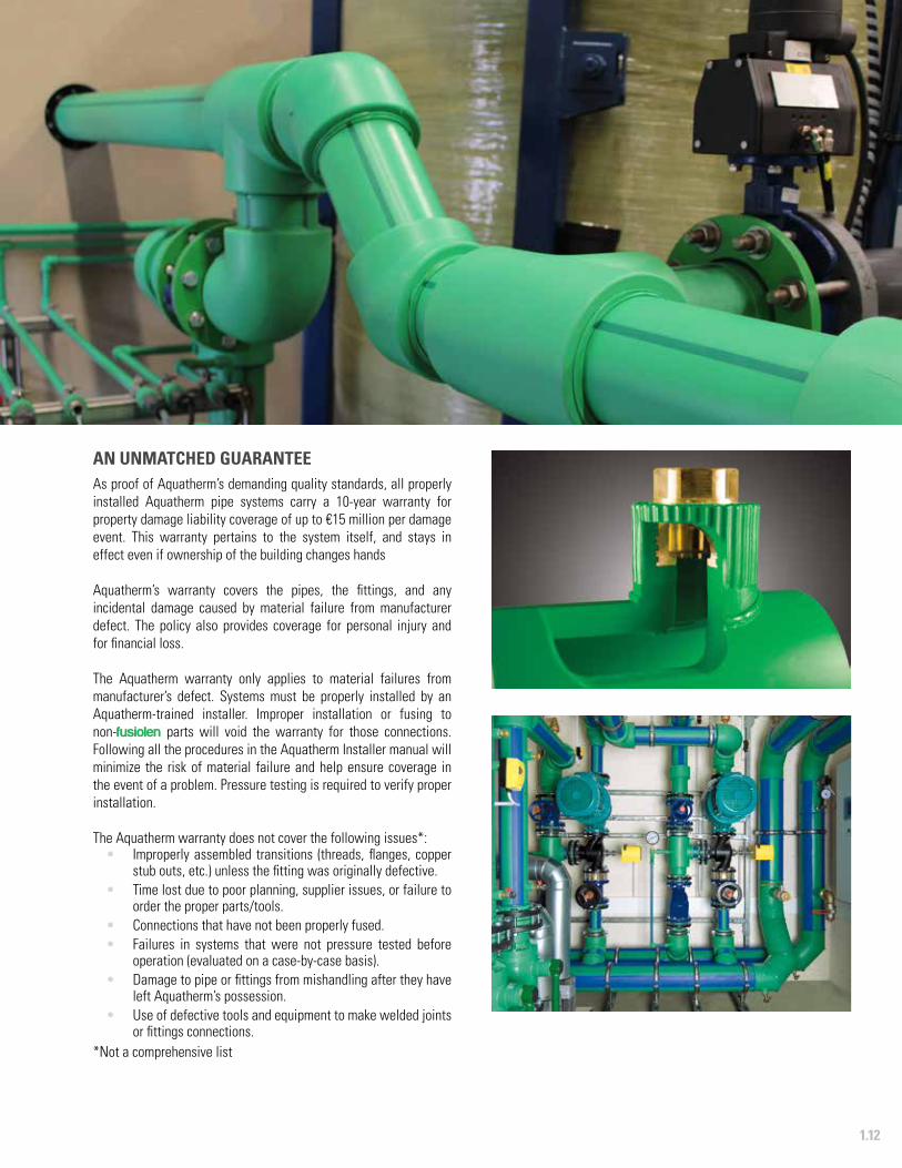
AN UNMATCHED GUARANTEEAs proof of Aquatherm’s demanding quality standards, all properly installed Aquatherm pipe systems carry a 10-year warranty for property damage liability coverage of up to €15 million per damage event. This warranty pertains to the system itself, and stays in effect even if ownership of the building changes hands
Aquatherm’s warranty covers the pipes, the fittings, and any incidental damage caused by material failure from manufacturer defect. The policy also provides coverage for personal injury and for financial loss.
The Aquatherm warranty only applies to material failures from manufacturer’s defect. Systems must be properly installed by an Aquatherm-trained installer. Improper installation or fusing to non-fusiolen parts will void the warranty for those connections. Following all the procedures in the Aquatherm Installer manual will minimize the risk of material failure and help ensure coverage in the event of a problem. Pressure testing is required to verify proper installation.
The Aquatherm warranty does not cover the following issues*:• Improperly assembled transitions (threads, flanges, copper
stub outs, etc.) unless the fitting was originally defective.• Time lost due to poor planning, supplier issues, or failure to
order the proper parts/tools.• Connections that have not been properly fused.• Failures in systems that were not pressure tested before
operation (evaluated on a case-by-case basis).• Damage to pipe or fittings from mishandling after they have
left Aquatherm’s possession. • Use of defective tools and equipment to make welded joints
or fittings connections.*Not a comprehensive list

1.13
FEATURES
ADVANTAGES• Lightweight pipe and fittings• Durable material• Full system compatibility• Rigid hanging pipe• Flexible lengths and connections• Easily prefabricated• Consistent results• Simple expansion control• Suitable for air testing*
*Damaged pipe or improper joining may cause the pipe or fittings to break apart during pressure testing. Follow all safety precautions when conducting a pressure test.
INSTALLATION ADVANTAGES FAST CONNECTION TIMESAquatherm pipes and fittings are assembled with heat fusion, a fast and simple process that involves heating the materials and sliding them together for a perfect connection every time.
Heat fusion can save over 50% on labor time compared to traditional welding and soldering and is comparable to the quickest labor-saving connection methods.
FUSION OUTLETSThis innovation allows for branch lines to be added after the mains are already in place, reducing labor times and giving the installer unparalleled flexibility.
Fusion outlets replace standard reducing tees and offer many advantages such as replacing two connections with one, having a lower pressure drop, and using less material.
USA-BASED FABRICATIONAs part of ongoing efforts to provide superior service to match its superior products, Aquatherm offers prefabrication options for manifolds and other complicated or large assemblies. Aquatherm’s Utah-based fabrication team also builds all the segmented fittings for increased accuracy and reduced lead times.
For a quote and lead time on a custom assembly, please submit your specifications to [email protected].
RIGID HANGING PIPEAquatherm pipes are designed to remain rigid on hangers, giving the pipe a clean, conventional layout with elbows and tees. This allows installers to create a craftsman’s appearance in the final product.
LIGHTWEIGHT MATERIALAquatherm’s PP-R pipes and fittings can weigh as little as 1/8th of an equivalent metal part, making it much easier to lift and carry around the jobsite. Installing larger spools and carrying the materials in fewer trips will speed the overall installation process and reduce worker fatigue.
FLEXIBLE LENGTHS AND CONNECTIONSHeat fusion connections have the same properties as the pipes and fittings, so there is a certain level of flexibility in the assembled pipe that makes it easy to prefabricate and move on-site without the risk of the joints cracking and leaking. This flexibility also allows for a wider range of applications and protects the pipe from seismic stresses.
CONSISTENT RESULTSOne of the major advantages of using PP-R and heat fusion is that the results are both reliable and consistent. The double bead of plastic allows for accurate visual inspection.
Aquatherm quality control
Labeling, shipping, and handling
Standards, regulations, and listings
Test certificates
QUALITY ASSURANCE2

QUALITY ASSURANCE
2.1
INSPECTION AND TESTINGThe equipment used in our manufacturing process (e.g., ultrasonic gauges) allows for constant observation and control of production. Any substandard products are isolated and recycled.
Pipes and fittings are only released to stock following the completion of proper testing and inspection. This data is documented and recorded for future reference.
EXTERNAL TESTINGIn addition to the extensive quality assurance testing conducted on site by Aquatherm, independent third-party auditing is carried out by several North American certification agencies including NSF International, IAPMO, and ICC.
These agencies perform unannounced plant inspections each year to verify that the materials, processes, quality control, and piping system performance are in accordance with national and international consensus standards.
FINAL INSPECTIONThe final inspection and associated tests cover the following:
• dimensional control• surface finish• measurement of the melt flow index• impact bending test• heat reversion test• homogeneity of the material• internal pressure test
Once the final inspection has been completed, pipes and fittings are stocked and shipped worldwide upon request to Aquatherm’s international partners.
Aquatherm’s products are manufactured and tested at the company headquarters in Attendorn, Germany.
To ensure consistency and quality in our products, Aquatherm has established a thorough production process that includes:
• testing and acceptance of incoming materials• in-process inspection and testing • process control at all stages• final inspection and testing
Aquatherm complies with all relevant regulations and standards for the quality control of potable water pipe systems established by:
• NSF• CSA• CFIA• ASTM
• ICC• IAPMO• ISO• DIN
Our strict manufacturing standards are backed up by decades of experience in the extrusion and injection molding industries.
RAW MATERIALSThe materials used to make Aquatherm products, such as the PP-R granules used to produce fusiolen® PP-R and the metal used in transition fittings, are rigorously tested and uniformly sourced.
Preproduction samples are examined in the laboratory to verify structural integrity, dimensional accuracy, and surface finish. This testing ensures that all incoming materials conform to our own rigourous standards prior to production.
QUALITY CONTROL
2.2
QUALITY ASSURANCE
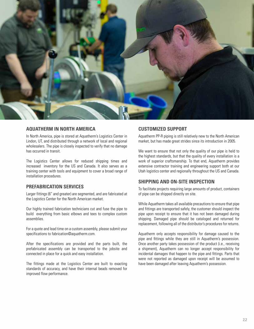
AQUATHERM IN NORTH AMERICAIn North America, pipe is stored at Aquatherm’s Logistics Center in Lindon, UT, and distributed through a network of local and regional wholesalers. The pipe is closely inspected to verify that no damage has occurred in transit.
The Logistics Center allows for reduced shipping times and increased inventory for the US and Canada. It also serves as a training center with tools and equipment to cover a broad range of installation procedures.
PREFABRICATION SERVICESLarger fittings (6” and greater) are segmented, and are fabricated at the Logistics Center for the North American market.
Our highly trained fabrication technicians cut and fuse the pipe to build everything from basic elbows and tees to complex custom assemblies.
For a quote and lead time on a custom assembly, please submit yourspecifications to [email protected].
After the specifications are provided and the parts built, the prefabricated assembly can be transported to the jobsite and connected in place for a quick and easy installation.
The fittings made at the Logistics Center are built to exacting standards of accuracy, and have their internal beads removed for improved flow performance.
CUSTOMIZED SUPPORTAquatherm PP-R piping is still relatively new to the North American market, but has made great strides since its introduction in 2005.
We want to ensure that not only the quality of our pipe is held to the highest standards, but that the quality of every installation is a work of superior craftsmanship. To that end, Aquatherm provides extensive contractor training and engineering support both at our Utah logistics center and regionally throughout the US and Canada.
SHIPPING AND ON-SITE INSPECTIONTo facilitate projects requiring large amounts of product, containers of pipe can be shipped directly on site.
While Aquatherm takes all available precautions to ensure that pipe and fittings are transported safely, the customer should inspect the pipe upon receipt to ensure that it has not been damaged during shipping. Damaged pipe should be cataloged and returned for replacement, following all of the distributor’s procedures for returns.
Aquatherm only accepts responsibility for damage caused to the pipe and fittings while they are still in Aquatherm’s possession. Once another party takes possession of the product (i.e., receiving a shipment), Aquatherm can no longer accept responsibility for incidental damages that happen to the pipe and fittings. Parts that were not reported as damaged upon receipt will be assumed to have been damaged after leaving Aquatherm’s possession.
QUALITY ASSURANCE
2.3
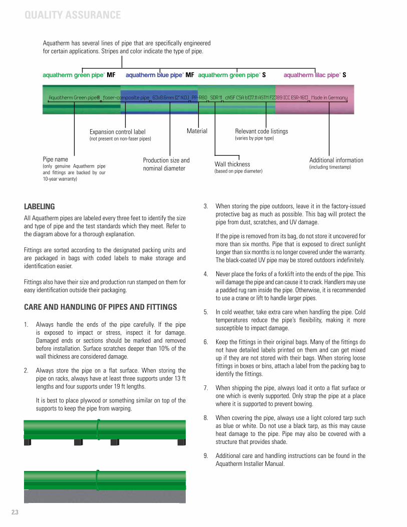
LABELINGAll Aquatherm pipes are labeled every three feet to identify the size and type of pipe and the test standards which they meet. Refer to the diagram above for a thorough explanation.
Fittings are sorted according to the designated packing units and are packaged in bags with coded labels to make storage and identification easier.
Fittings also have their size and production run stamped on them for easy identification outside their packaging.
CARE AND HANDLING OF PIPES AND FITTINGS
1. Always handle the ends of the pipe carefully. If the pipe is exposed to impact or stress, inspect it for damage. Damaged ends or sections should be marked and removed before installation. Surface scratches deeper than 10% of the wall thickness are considered damage.
2. Always store the pipe on a flat surface. When storing the pipe on racks, always have at least three supports under 13 ft lengths and four supports under 19 ft lengths.
It is best to place plywood or something similar on top of the supports to keep the pipe from warping.
3. When storing the pipe outdoors, leave it in the factory-issued protective bag as much as possible. This bag will protect the pipe from dust, scratches, and UV damage.
If the pipe is removed from its bag, do not store it uncovered for more than six months. Pipe that is exposed to direct sunlight longer than six months is no longer covered under the warranty. The black-coated UV pipe may be stored outdoors indefinitely.
4. Never place the forks of a forklift into the ends of the pipe. This will damage the pipe and can cause it to crack. Handlers may use a padded rug ram inside the pipe. Otherwise, it is recommended to use a crane or lift to handle larger pipes.
5. In cold weather, take extra care when handling the pipe. Cold temperatures reduce the pipe’s flexibility, making it more susceptible to impact damage.
6. Keep the fittings in their original bags. Many of the fittings do not have detailed labels printed on them and can get mixed up if they are not stored with their bags. When storing loose fittings in boxes or bins, attach a label from the packing bag to identify the fittings.
7. When shipping the pipe, always load it onto a flat surface or one which is evenly supported. Only strap the pipe at a place where it is supported to prevent bowing.
8. When covering the pipe, always use a light colored tarp such as blue or white. Do not use a black tarp, as this may cause heat damage to the pipe. Pipe may also be covered with a structure that provides shade.
9. Additional care and handling instructions can be found in the Aquatherm Installer Manual.
Aquatherm Green pipe® faser-composite pipe 63x8.6mm (2” N.D.) PP-R80 SDR 11 cNSF CSA b137.11 ASTM F2389 ICC ESR-1613 Made in Germany
Aquatherm has several lines of pipe that are specifically engineered for certain applications. Stripes and color indicate the type of pipe.
Pipe name(only genuine Aquatherm pipe and fittings are backed by our 10-year warranty)
Expansion control label (not present on non-faser pipes)
Production size and nominal diameter
Material
Wall thickness (based on pipe diameter)
Relevant code listings (varies by pipe type)
Additional information(including timestamp)
aquatherm green pipe® MF aquatherm blue pipe® MF aquatherm green pipe® S aquatherm lilac pipe® S
Aquatherm Green pipe® faser-composite pipe 63x8.6mm (2” N.D.) PP-R80 SDR 11 cNSF CSA b137.11 ASTM F2389 ICC ESR-1613 Made in Germany
2.4
QUALITY ASSURANCE
• NSF Standard 61 (C.HOT 180 °F/82 °C) Suitable for potable water
• NSF Standard 14 Meets piping performance requirements
• NSF Standard 51 Suitable for food processing up to 212 °F (100 °C)
• CFIA #A508 Canadian Food Inspection Agency approval #A508
• ICC ESR-1613 / PMG Listing 1014Polypropylene pipe and fittings meet or exceed North American standards
• DIN EN ISO 9001 Quality management systems: requirements
• IPC 2009 Sec. 605 Water distribution & Water service
• IMC 2009 Chapter 12 Hydronic piping
• IRC 2009 Chapter 21 & 26 Hydronic piping & Plumbing
• UMC 2009 Chapter 12 Hydronic piping
• UPC 2012 Chapter 6 Water distribution & Building supply
• IAPMO File M-6022 Mechanical
• IAPMO File 5053 Plumbing
• ASTM F2389Standard specification for pressure rated polypropylene (PP) piping systems
• CSA B137.11Polypropylene (PP-R) pipe and fittings for pressure applications
• CSA B214Polypropylene (PP-R) pipe and fittings for hydronic applications
• BNQ 3660-950Safety of products and materials in contact with drinking water
• ISO 15874Plastic pipe system for hot and cold water installation: polypropylene
• ASTM F2023Standard test method for evaluating the oxidative resistance of plastic piping to hot chlorinated water
• ASTM D 635Standard test method for rate of burning and/or extent and time of burning of plastics in a horizontal position
• FM 1635 For wet pipe automatic sprinkler systems in light-hazard occupancies
• NFPA 13, 13D and 13RStandard for the installation of sprinkler systems in one/two-family dwellings & manufactured homes
• DIN EN ISO 14001 Standard for environmental management
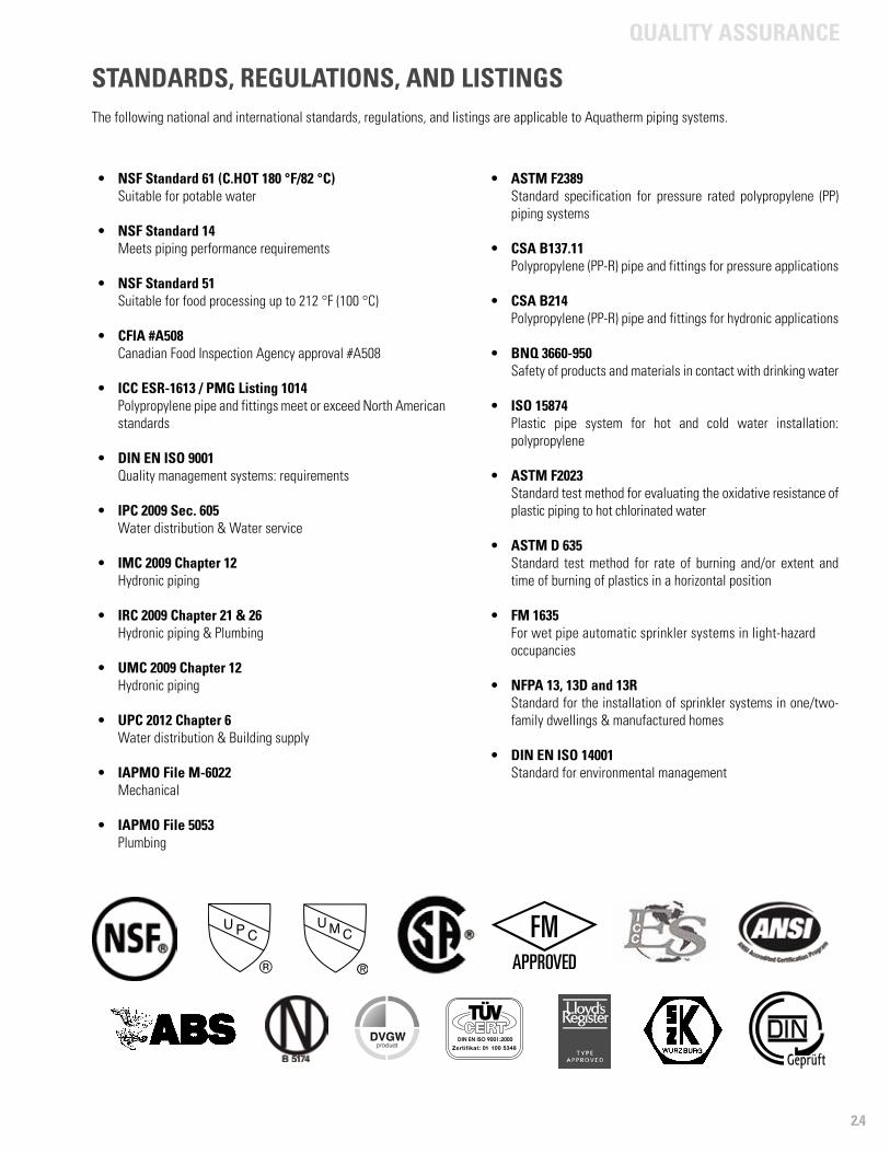
STANDARDS, REGULATIONS, AND LISTINGSThe following national and international standards, regulations, and listings are applicable to Aquatherm piping systems.

QUALITY ASSURANCE
2.5
IAPMO Research and Testing, Inc. is a product certification body which tests and inspects samples taken from the supplier's stock or from the market or acombination of both to verify compliance to the requirements of applicable codes and standards. This activity is coupled with periodic surveillance of thesupplier's factory and warehouses as well as the assessment of the supplier's Quality Assurance System. This listing is subject to the conditions set forth inthe characteristics below and is not to be construed as any recommendation, assurance or guarantee by IAPMO Research and Testing, Inc. of the productacceptance by Authorities Having Jurisdiction.
This listing period is based upon the last date of the month indicated on the Effective Date and Void After Date shown above. Any change in material,manufacturing process, marking or design without having first obtained the approval of the Product Certification Committee, or any evidence ofnon-compliance with applicable codes and standards or of inferior workmanship, may be deemed sufficient cause for revocation of this listing.Production of or reference to this form for advertising purposes may be made only by specific written permission of IAPMO Research and Testing, Inc.Any alteration of this certificate could be grounds for revocation of the listing.
Effective Date: April 2013 Void After: April 2014
Product: Pressure Rated Polypropylene Piping Systems File No. M-6022
Issued To: Aquatherm GmbhBiggen 5D-57439 Attendorn,Germany
Identification: Pipe shall be marked at intervals of not more than 5 ft. with the
manufacturer's name or trademark, nominal size, for metric series pipe - the
term "metric" and the dimension ratio or both the outside diameter and wall
thickness, IPS series pipe shall include "Schedule 80" or "SCH 80", type of
material (PP-R) and classification number (80 or 100), pressure rating and
temperature for which pressure rating is valid, the designation "F2389",
manufacturer's production code, and pipe intended for the transport of
potable water shall bear the mark of the lab making such evaluation.
Fittings shall be marked with the manufacturer's name or trademark, nominal
size, dimension ratio or schedule for corresponding pipe and type of material
(PP-R). The fitting or packaging shall be marked with "Metric" or "NPT" for
threaded fittings, and the designation "F2389". All products shall bear the
UMC certification mark.
Characteristics: Pressure rated polypropylene pipe and fittings manufactured in accordance
with ASTM F2389. To be installed per the manufacturer's instructions.
Products listed on this certificate have been tested by an IAPMO R&T
IAPMO Research and Testing, Inc. is a product certification body which tests and inspects samples taken from the supplier's stock or from the market or acombination of both to verify compliance to the requirements of applicable codes and standards. This activity is coupled with periodic surveillance of thesupplier's factory and warehouses as well as the assessment of the supplier's Quality Assurance System. This listing is subject to the conditions set forth inthe characteristics below and is not to be construed as any recommendation, assurance or guarantee by IAPMO Research and Testing, Inc. of the productacceptance by Authorities Having Jurisdiction.
This listing period is based upon the last date of the month indicated on the Effective Date and Void After Date shown above. Any change in material,manufacturing process, marking or design without having first obtained the approval of the Product Certification Committee, or any evidence ofnon-compliance with applicable codes and standards or of inferior workmanship, may be deemed sufficient cause for revocation of this listing.Production of or reference to this form for advertising purposes may be made only by specific written permission of IAPMO Research and Testing, Inc.Any alteration of this certificate could be grounds for revocation of the listing.
Effective Date: June 2013 Void After: June 2014
Product: Pressure Rated Polypropylene Piping Systems File No. 5053
Issued To: AQUATHERM GMBHBiggen 5D-57439 Attendorn,Germany
Identification: Pipe shall be marked at intervals of not more than 5 ft. with the
manufacturer's name or trademark, nominal size, for metric series pipe - the
term "metric" and the dimension ratio or both the outside diameter and wall
thickness, IPS series pipe shall include "Schedule 80" or "SCH 80", type of
material (PP-R) and classification number (80 or 100), pressure rating and
temperature for which pressure rating is valid, the designation "F2389",
manufacturer's production code, and pipe intended for the transport of
potable water shall bear the mark of the lab making such evaluation.
Fittings shall be marked with the manufacturer's name or trademark, nominal
size, dimension ratio or schedule for corresponding pipe and type of material
(PP-R). The fitting or packaging shall be marked with "Metric" or "NPT" for
threaded fittings, and the designation "F2389". All products shall bear the
UPC® certification mark.
Characteristics: Pressure rated polypropylene pipe and fittings manufactured in accordance
with ASTM F2389. To be installed per the manufacturer's instructions and the
latest edition of the Uniform Plumbing Code.

PLANNING
PLA
NN
ING
Chapter
3
Planning and engineering with Aquatherm
Working pressureIntegration with other systems
Flame spread and smoke developedUsing the I-Codes/Using the IAPMO codes
Special applications
System considerationsPipe sizing by flow rate Flow velocity and head loss
Equivalent lengths of fittingsMaximum pull force
PLANNING3
PLANNING
3.1
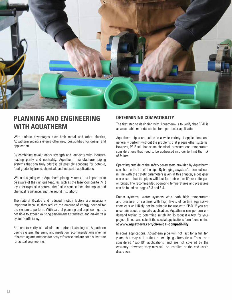
PLANNING AND ENGINEERING WITH AQUATHERMWith unique advantages over both metal and other plastics, Aquatherm piping systems offer new possibilities for design and application.
By combining revolutionary strength and longevity with industry-leading purity and neutrality, Aquatherm manufactures piping systems that can truly address all possible concerns for potable, food-grade, hydronic, chemical, and industrial applications.
When designing with Aquatherm piping systems, it is important to be aware of their unique features such as the faser-composite (MF) layer for expansion control, the fusion connections, the impact and chemical resistance, and the sound insulation.
The natural R-value and reduced friction factors are especially important because they reduce the amount of energy needed for the system to perform. With careful planning and engineering, it is possible to exceed existing performance standards and maximize a system’s efficiency.
Be sure to verify all calculations before installing an Aquatherm piping system. The sizing and insulation recommendations given in this catalog are intended for easy reference and are not a substitute for actual engineering.
DETERMINING COMPATIBILITYThe first step to designing with Aquatherm is to verify that PP-R is an acceptable material choice for a particular application.
Aquatherm pipes are suited to a wide variety of applications and generally perform without the problems that plague other systems. However, PP-R still has some chemical, pressure, and temperature considerations that need to be addressed in order to limit the risk of failure.
Operating outside of the safety parameters provided by Aquatherm can shorten the life of the pipe. By bringing a system’s intended load in line with the safety parameters given in this chapter, a designer can ensure that the pipes will last for their entire 60-year lifespan or longer. The recommended operating temperatures and pressures can be found on pages 3.3 and 3.4.
Steam systems, water systems with both high temperature and pressure, or systems with high levels of certain aggressive chemicals will likely not be suitable for use with PP-R. If you are uncertain about a specific application, Aquatherm can perform on-demand testing to determine suitability. To request a test for your project, fill out and submit the special applications form found online at www.aquatherm.com/chemical-compatibility.
In some applications, Aquatherm pipe will not last for a full ten years, but may still outlast other piping alternatives. These are considered “sub-10” applications, and are not covered by the warranty. However, they may still be installed at the end user’s discretion.

PLANNING
3.2
CHOOSING YOUR SYSTEMAlthough all Aquatherm systems share similar characteristics, they are also engineered for use in certain applications. Choosing the correct system for the application will maximize performance and minimize material costs.
As a general rule, aquatherm green pipe® should be used for potable and food-grade applications while aquatherm blue pipe® is used for heating and cooling, compressed air, and a variety of industrial applications. aquatherm lilac pipe® is intended for use in gray water systems. A more detailed list of suitable applications can be found in chapter 1.
Only MF (multi-layer faser-composite) pipes should be used on heated or chilled applications, to reduce linear expansion (see page 4.8). Additionally, Aquatherm recommends using the thinnest-walled pipe that will meet the temperature and pressure ratings required by the system. Aquatherm’s recommended operating parameters already contain a significant safety factor.
DETERMINING EFFICIENCYAquatherm pipes have a high flow coefficient, and do not suffer from a loss of flow over time due to corrosion. However, due to differences in the OD, flow calculations will need to be done specifically for the Aquatherm pipe.
Information regarding flow rates, flow speed, head loss and flow loss through fittings can be found on page 3.9.
ADDRESSING ADDITIONAL NEEDSWhen installing Aquatherm in a plenum space, special considerations need to be taken to meet building codes. Information regarding plenum-rated options can be found on page 3.6.
If the Aquatherm pipe is being installed outside, the pipe will need to be protected from UV radiation. Information regarding UV protection can be found on page 3.8. Information regarding thrust blocking, vibration isolation, direct-boiler connections, and firestopping can also be found there.
PLANNING
3.3
SYSTEMS WITH CONSTANT OPERATING PARAMETERS (60-YEAR EXPECTED MINIMUM)
Temperatureaquatherm green pipe®
SDR 11 (non-MF)aquatherm green pipe®
SDR 7.4 (MF)aquatherm blue pipe®
SDR 11 (MF)aquatherm blue pipe®
SDR 17.6 (MF)
Permissible working pressure (psi)
50 °F 195 380 325 160
80 °F 170 320 255 125
100 °F 135 255 210 95
120 °F 110 215 180 80
140 °F 95 180 150 70
160 °F - 120 100 45
180 °F - 100 62 30
200 °F - 45 30 15
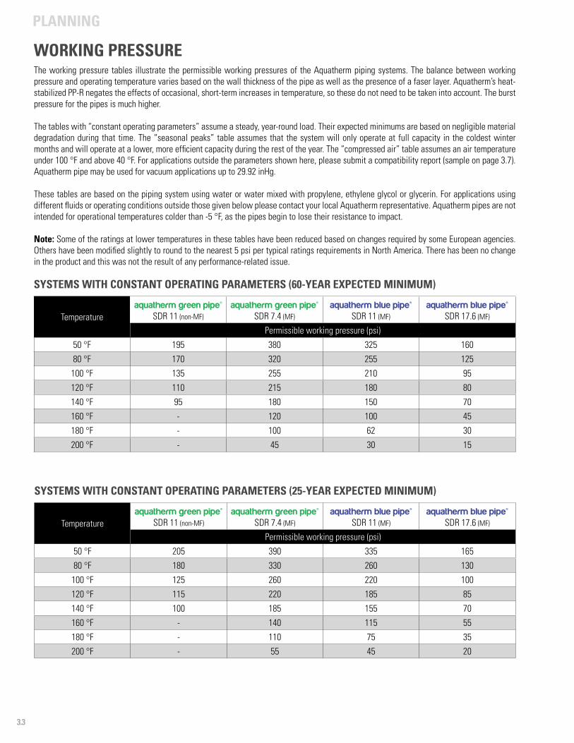
The working pressure tables illustrate the permissible working pressures of the Aquatherm piping systems. The balance between working pressure and operating temperature varies based on the wall thickness of the pipe as well as the presence of a faser layer. Aquatherm’s heat-stabilized PP-R negates the effects of occasional, short-term increases in temperature, so these do not need to be taken into account. The burst pressure for the pipes is much higher.
The tables with “constant operating parameters” assume a steady, year-round load. Their expected minimums are based on negligible material degradation during that time. The “seasonal peaks” table assumes that the system will only operate at full capacity in the coldest winter months and will operate at a lower, more efficient capacity during the rest of the year. The “compressed air” table assumes an air temperature under 100 °F and above 40 °F. For applications outside the parameters shown here, please submit a compatibility report (sample on page 3.7). Aquatherm pipe may be used for vacuum applications up to 29.92 inHg.
These tables are based on the piping system using water or water mixed with propylene, ethylene glycol or glycerin. For applications using different fluids or operating conditions outside those given below please contact your local Aquatherm representative. Aquatherm pipes are not intended for operational temperatures colder than -5 °F, as the pipes begin to lose their resistance to impact.
Note: Some of the ratings at lower temperatures in these tables have been reduced based on changes required by some European agencies. Others have been modified slightly to round to the nearest 5 psi per typical ratings requirements in North America. There has been no change in the product and this was not the result of any performance-related issue.
SYSTEMS WITH CONSTANT OPERATING PARAMETERS (25-YEAR EXPECTED MINIMUM)
Temperatureaquatherm green pipe®
SDR 11 (non-MF)aquatherm green pipe®
SDR 7.4 (MF)aquatherm blue pipe®
SDR 11 (MF)aquatherm blue pipe®
SDR 17.6 (MF)
Permissible working pressure (psi)
50 °F 205 390 335 165
80 °F 180 330 260 130
100 °F 125 260 220 100
120 °F 115 220 185 85
140 °F 100 185 155 70
160 °F - 140 115 55
180 °F - 110 75 35
200 °F - 55 45 20
WORKING PRESSURE
PLANNING
3.4
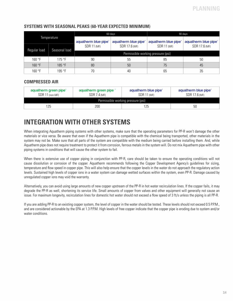
SYSTEMS WITH SEASONAL PEAKS (60-YEAR EXPECTED MINIMUM)
Temperature60 days 90 days
aquatherm blue pipe® SDR 11 (MF)
aquatherm blue pipe® SDR 17.6 (MF)
aquatherm blue pipe® SDR 11 (MF)
aquatherm blue pipe® SDR 17.6 (MF)
Regular load Seasonal loadPermissible working pressure (psi)
160 °F 175 °F 90 55 85 50
160 °F 185 °F 80 50 75 45
160 °F 195 °F 70 40 65 35
aquatherm green pipe®SDR 11 (non-MF)
aquatherm green pipe ® SDR 7.4 (MF)
aquatherm blue pipe® SDR 11 (MF)
aquatherm blue pipe® SDR 17.6 (MF)
Permissible working pressure (psi)
125 200 125 50
COMPRESSED AIR
When integrating Aquatherm piping systems with other systems, make sure that the operating parameters for PP-R won’t damage the other materials or vice versa. Be aware that even if the Aquatherm pipe is compatible with the chemical being transported, other materials in the system may not be. Make sure that all parts of the system are compatible with the medium being carried before installing them. And, while Aquatherm pipe does not require treatment to protect it from corrosion, ferrous metals in the system will. Do not mix Aquatherm pipe with other piping systems in conditions that will cause the other system to fail.
When there is extensive use of copper piping in conjunction with PP-R, care should be taken to ensure the operating conditions will not cause dissolution or corrosion of the copper. Aquatherm recommends following the Copper Development Agency’s guidelines for sizing, temperature and flow speed in copper pipe. This will also help ensure that the copper levels in the water do not approach the regulatory action levels. Sustained high levels of copper ions in a water system can damage wetted surfaces within the system, even PP-R. Damage caused by unregulated copper ions may void the warranty.
Alternatively, you can avoid using large amounts of new copper upstream of the PP-R in hot water recirculation lines. If the copper fails, it may degrade the PP-R as well, shortening its service life. Small amounts of copper from valves and other equipment will generally not cause an issue. For maximum longevity, recirculation lines for domestic hot water should not exceed a flow speed of 3 ft/s unless the piping is all PP-R.
If you are adding PP-R to an existing copper system, the level of copper in the water should be tested. These levels should not exceed 0.5 P.P.M., and are considered actionable by the EPA at 1.3 P.P.M. High levels of free copper indicate that the copper pipe is eroding due to system and/or water conditions.
INTEGRATION WITH OTHER SYSTEMS
PLANNING
3.5
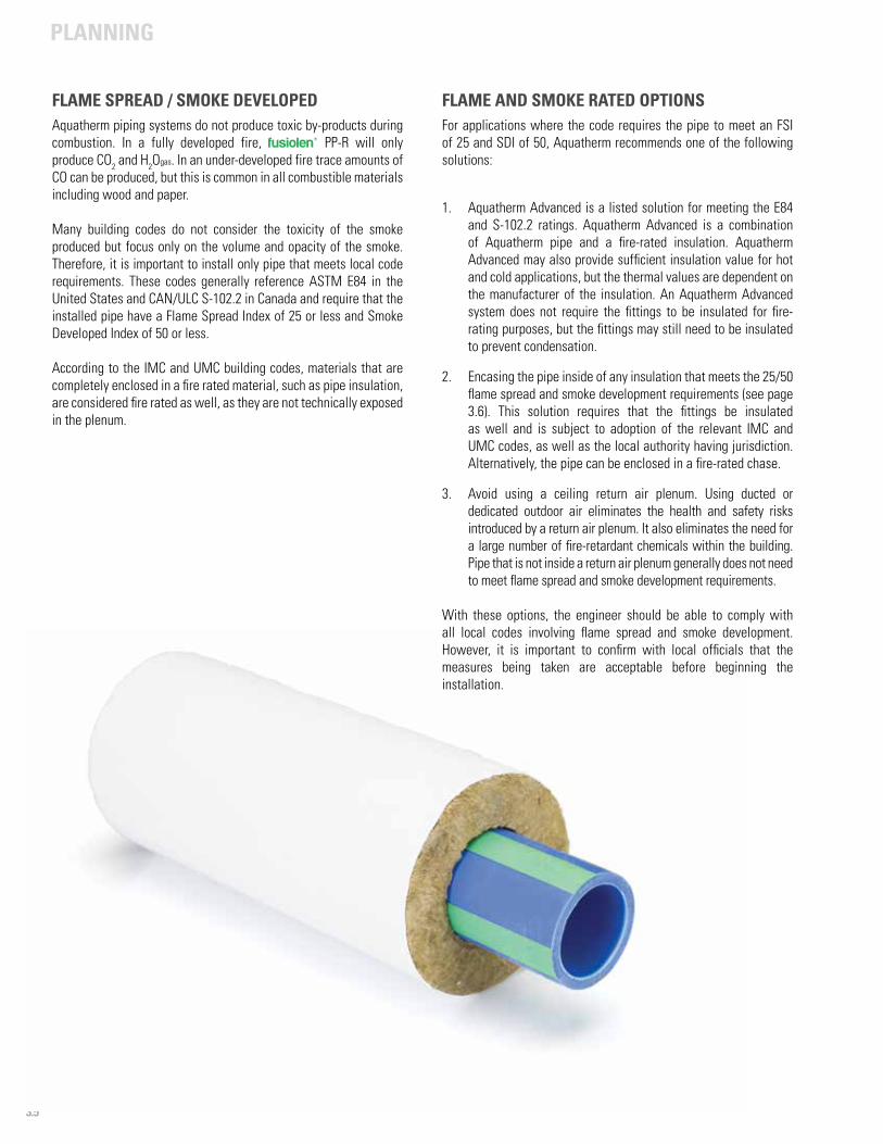
FLAME AND SMOKE RATED OPTIONSFor applications where the code requires the pipe to meet an FSI of 25 and SDI of 50, Aquatherm recommends one of the following solutions:
1. Aquatherm Advanced is a listed solution for meeting the E84 and S-102.2 ratings. Aquatherm Advanced is a combination of Aquatherm pipe and a fire-rated insulation. Aquatherm Advanced may also provide sufficient insulation value for hot and cold applications, but the thermal values are dependent on the manufacturer of the insulation. An Aquatherm Advanced system does not require the fittings to be insulated for fire-rating purposes, but the fittings may still need to be insulated to prevent condensation.
2. Encasing the pipe inside of any insulation that meets the 25/50 flame spread and smoke development requirements (see page 3.6). This solution requires that the fittings be insulated as well and is subject to adoption of the relevant IMC and UMC codes, as well as the local authority having jurisdiction. Alternatively, the pipe can be enclosed in a fire-rated chase.
3. Avoid using a ceiling return air plenum. Using ducted or dedicated outdoor air eliminates the health and safety risks introduced by a return air plenum. It also eliminates the need for a large number of fire-retardant chemicals within the building. Pipe that is not inside a return air plenum generally does not need to meet flame spread and smoke development requirements.
With these options, the engineer should be able to comply with all local codes involving flame spread and smoke development. However, it is important to confirm with local officials that the measures being taken are acceptable before beginning the installation.
FLAME SPREAD / SMOKE DEVELOPEDAquatherm piping systems do not produce toxic by-products during combustion. In a fully developed fire, fusiolen® PP-R will only produce CO2 and H2Ogas. In an under-developed fire trace amounts of CO can be produced, but this is common in all combustible materials including wood and paper.
Many building codes do not consider the toxicity of the smoke produced but focus only on the volume and opacity of the smoke. Therefore, it is important to install only pipe that meets local code requirements. These codes generally reference ASTM E84 in the United States and CAN/ULC S-102.2 in Canada and require that the installed pipe have a Flame Spread Index of 25 or less and Smoke Developed Index of 50 or less.
According to the IMC and UMC building codes, materials that are completely enclosed in a fire rated material, such as pipe insulation, are considered fire rated as well, as they are not technically exposed in the plenum.
PLANNING
3.6
USING THE I-CODESUnder the IMC, materials exposed within plenums are required to meet the ASTM E 84 test for flame spread and smoke development. As given in the 2006 edition:
602.2.1 Materials exposed within plenumsExcept as required by Sections 602.2.1.1 through 602.2.1.5, materials within plenums shall be noncombustible or shall have a flame spread index of not more than 25 and a smoke-developed index of not more than 50 when tested in accordance with ASTM E 84.
Exceptions:
5. Combustible materials enclosed in noncombustible raceways or enclosures, approved gypsum board assemblies or enclosed in materials listed and labeled for such application.
Exception 5 excluded materials that were enclosed within noncombustible (or otherwise approved) materials, as the enclosed materials are technically concealed, rather than exposed. This exception was further detailed in the 2012 edition, making the intent of the previous editions clear:
602.2.1 Materials exposed within plenumsExcept as required by Sections 602.2.1.1 through 602.2.1.5, materials within plenums shall be noncombustible or shall have a flame spread index of not more than 25 and a smoke-developed index of not more than 50 when tested in accordance with ASTM E 84 or UL 723.
Exceptions:
5. Combustible materials fully enclosed within one of the following:5.1 Continuous noncombustible raceways or enclosures5.2 Approved gypsym board assemblies5.3 Materials listed and labeled for installation within a plenum.
Under the IMC, Aquatherm pipe may be safely installed in a plenum if the pipe and fittings are contained within an insulation that meets the ASTM E 84 test requirements. This is due to the fact that pipes enclosed within the insulation are no longer considered exposed inside the plenum. Where insulation is not needed, a plenum-rated wrap will also suffice.
USING THE IAPMO CODES The UMC contains similar requirements to the IMC in regards to plenums. In turn, the exceptions are similar, although the UMC does not offer as detailed of an exception. In the 2009 edition, it reads:
602.2 Combustibles within Ducts or PlenumsMaterials exposed within ducts or plenums shall be noncombustible or shall have a flame spread index not greater than twenty five (25) and a smoke developed index not greater than fifty (50), when tested as a composite product in accordance with one of the following test methods: NFPA 255, Method of Test of Surface Burning Characteristics of Building Materials, ASTM E 84, Surface Burning Characteristics of Building Materials, or UL 723, Test for Surface Burning Characteristics of Building Materials except as indicated below.
In this case, materials that are exposed are required to be non-combustible or meet flame spread and smoke developed requirements. Materials that are not exposed within the plenum are therefore excluded. This follows the logic and intent of the IMC.
More recent versions maintain this language, but simplify the associated test methods. In the 2012 edition:
602.2 Combustibles within Ducts or PlenumsMaterials exposed within ducts or plenums shall be noncombustible or shall have a flame spread index not greater than twenty five (25) and a smoke developed index not greater than fifty (50), when tested as a composite product in accordance with ASTM E 84 or UL 723, except as indicated below.
In short, under the UMC, Aquatherm pipe may be safely installed in a plenum as long as the pipe is not exposed to the plenum space. This is easily solved by encasing the pipe and fittings in a plenum-rated insulation. Where insulation is not required, a plenum-rated wrap may be used instead.
OTHER SOLUTIONSIf the plenum-rating options discussed here will not suffice for a particular installation, please contact Aquatherm’s Engineering Support department in Lindon, Utah by phone (801-805-6657) or email ([email protected]).
PLANNING
3.7
use online version onlyex
ample
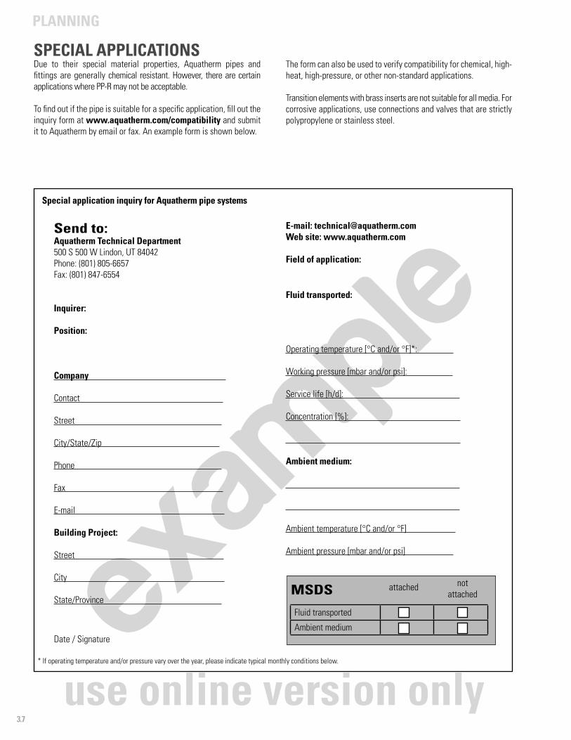
SPECIAL APPLICATIONSDue to their special material properties, Aquatherm pipes and fittings are generally chemical resistant. However, there are certain applications where PP-R may not be acceptable.
To find out if the pipe is suitable for a specific application, fill out the inquiry form at www.aquatherm.com/compatibility and submit it to Aquatherm by email or fax. An example form is shown below.
Special application inquiry for Aquatherm pipe systems
Send to: Aquatherm Technical Department500 S 500 W Lindon, UT 84042Phone: (801) 805-6657Fax: (801) 847-6554
Inquirer:
Position:
Company
Contact
Street
City/State/Zip
Phone
Fax
Building Project:
Street
City
State/Province
Date / Signature
E-mail: [email protected] site: www.aquatherm.com
Field of application:
Fluid transported:
Operating temperature [°C and/or °F]*:
Working pressure [mbar and/or psi]:
Service life [h/d]:
Concentration [%]:
Ambient medium:
Ambient temperature [°C and/or °F]
Ambient pressure [mbar and/or psi]
MSDS
Fluid transported
Ambient medium
attached notattached
* If operating temperature and/or pressure vary over the year, please indicate typical monthly conditions below.
The form can also be used to verify compatibility for chemical, high-heat, high-pressure, or other non-standard applications.
Transition elements with brass inserts are not suitable for all media. For corrosive applications, use connections and valves that are strictly polypropylene or stainless steel.
PLANNING
3.8
FIRE STOPPINGPolypropylene is a combustible material and must be treated as such. Generally, when penetrating a fire-rated assembly, fire stopping must be used to give the penetration a fire rating that matches the rating of the assembly. However, building code requirements vary greatly between areas.
It is critical that fire stopping issues be addressed early in the design and construction of a project. Please contact your fire stopping manufacturer for current listing and installation requirements.
Visit www.aquatherm.com/firestopping for a current list of manufacturers who have tested and listed their products for use with Aquatherm piping systems.
SYSTEM PROTECTIONAllowing a pump to operate for an extended period of time with zero flow passing through it can result in the pump and adjoining piping system reaching temperatures and pressures far above those recommended by Aquatherm (see pages 3.3 and 3.4).
While Aquatherm’s heat stabilization will protect the pipe from brief exposure to extreme conditions, prolonged exposure can weaken the pipe and fittings considerably, potentially causing them and other components to fail.
It is recommended that the designer provide a sensor system that will warn of temperatures over 180 °F, an automatic temperature and pressure relief valve at the pump discharge, or a similar preventative measure.
To protect the pipe from exposure to unacceptably high temperatures and pressures that could occur due to prolonged “dead heading” (pump operating at full speed with flow completely restricted), Aquatherm recommends temperature and pressure relief valves at the discharge of 3 horsepower and larger pumps.
THRUST BLOCKINGDue to the inherent strength and integrity of fused connections, thrust blocking is not required.
Anchors may still be necessary where buried pipe enters a building foundation or other locations to minimize pipe movement.
UV RESISTANCEPipes made from fusiolen® PP-R and fusiolen® PP-R C are normally not installed where they will be subject to UV radiation. UV radiation can damage and weaken the polypropylene chains over time. UV-rated solutions can be found on page 4.19.
ISOLATING PUMP-TO-PIPE CONNECTORSPP-R can absorb small vibrations, so isolators are not required if the pipe has some limited mobility on either side of the pump.
NOISE AND WATER HAMMERTo avoid noise generation and water hammer, the calculated flow rate should not exceed 8 ft/s. Buried pipe may run up to 12 ft/s, as noise generation is not an issue.
The surge pressure created in systems operating at 8 ft/s or lower velocity will be less than 50% of the maximum shock pressure the Aquatherm piping can withstand (725 psi). At higher flow velocity, the design engineer must still account for surge pressures and design accordingly.
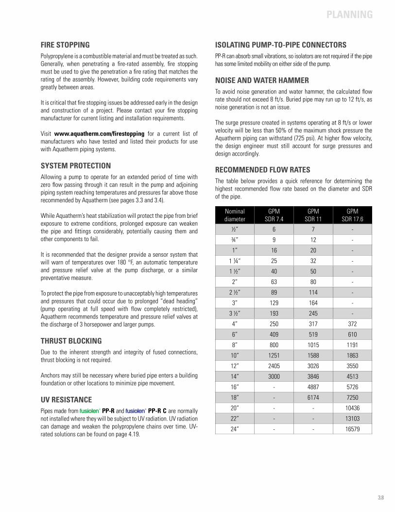
RECOMMENDED FLOW RATESThe table below provides a quick reference for determining the highest recommended flow rate based on the diameter and SDR of the pipe.
Nominal diameter
GPMSDR 7.4
GPMSDR 11
GPMSDR 17.6
½” 6 7 -
¾” 9 12 -
1” 16 20 -
1 ¼” 25 32 -
1 ½” 40 50 -
2” 63 80 -
2 ½” 89 114 -
3” 129 164 -
3 ½” 193 245 -
4” 250 317 372
6” 409 519 610
8” 800 1015 1191
10” 1251 1588 1863
12” 2405 3026 3550
14” 3000 3846 4513
16” - 4887 5726
18” - 6174 7250
20” - - 10436
22” - - 13103
24” - - 16579
PLANNING
3.9
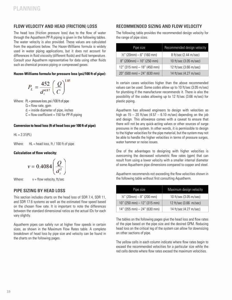
FLOW VELOCITY AND HEAD (FRICTION) LOSSThe head loss (friction pressure loss) due to the flow of water through the Aquatherm PP-R piping is given in the following tables. The water velocity is also provided. These values are calculated from the equations below. The Hazen-Williams formula is widely used in water piping applications, but it does not account for differences in fluid viscosity (different fluids) and fluid temperature. Consult your Aquatherm representative for data using other fluids such as chemical process piping or compressed gases.
Hazen-Williams formula for pressure loss (psi/100 ft of pipe):
Where: PL = pressure loss, psi /100 ft of pipeQ = flow rate, gpmdi = inside diameter of pipe, inchesC = flow coefficient = 150 for PP-R piping
Conversion to head loss (ft of head loss per 100 ft of pipe):
HL = 2.31(PL)
Where: HL = head loss, ft / 100 ft of pipe
Calculation of flow velocity:
Where: v = flow velocity, ft/sec
PIPE SIZING BY HEAD LOSSThis section includes charts on the head loss of SDR 7.4, SDR 11, and SDR 17.6 systems as well as the estimated flow speed based on the chosen flow rate. It is important to note the differences between the standard dimensional ratios as the actual IDs for each vary slightly.
Aquatherm pipes can safely run at higher flow speeds in certain sizes, as shown in the Maximum Flow Rates table. A complete breakdown of head loss by pipe size and velocity can be found in the charts on the following pages.
RECOMMENDED SIZING AND FLOW VELOCITYThe following table provides the recommended design velocity for the range of pipe sizes.
In certain cases velocities higher than the above recommended values can be used. Some codes allow up to 10 ft/sec (3.05 m/sec) for plumbing if the manufacturer recommends it. There is also the possibility of the codes allowing up to 12 ft/sec (3.66 m/sec) for plastic piping.
Aquatherm has allowed engineers to design with velocities as high as 15 – 20 ft/sec (4.57 – 6.10 m/sec) depending on the job and design. This allowance comes with a caveat to ensure that there will not be any quick-acting valves or other sources of surge pressures in the system. In other words, it is permissible to design to the higher velocities for the pipe material, but the system may not be able to handle the higher velocities in terms of pressure surges, water hammer or noise issues.
One of the advantages to designing with higher velocities is overcoming the decreased volumetric flow rates (gpm) that can result from using a lower velocity with a smaller internal diameter of some Aquatherm pipe dimensions compared to copper and steel.
Aquatherm recommends not exceeding the flow velocities shown in the following table without first consulting Aquatherm.
The tables on the following pages give the head loss and flow rates of the pipe based on the pipe size and the desired GPM. Reducing head loss on the critical leg of the system can allow for downsizing on other sections of pipe.
The yellow cells in each column indicate where flow rates begin to exceed the recommended velocities for a particular size while the red cells denote where flow rates exceed the maximum velocities.
Pipe size Recommended design velocity
½” (20mm) – 6” (160 mm) 8 ft/sec (2.44 m/sec)
8” (200mm) – 10” (250 mm) 10 ft/sec (3.05 m/sec)
12” (315 mm) – 18” (450 mm) 12 ft/sec (3.66 m/sec)
20” (500 mm) – 24” (630 mm) 14 ft/sec (4.27 m/sec)
Pipe size Maximum design velocity
½” (20mm) – 8” (200 mm) 10 ft/sec (3.05 m/sec)
10” (250 mm) – 12” (315 mm) 12 ft/sec (3.66 m/sec)
14” (355 mm) – 24” (630 mm) 14 ft/sec (4.27 m/sec)

PLANNING
3.10
Q
Dimension
½”20 mm
¾”25 mm
1”32 mm
1 ¼”40 mm
1 ½”50 mm
2”63 mm
2 ½”75 mm
3”90 mm
3 ½”110 mm
4”125 mm
6”160 mm
8”200 mm
10”250 mm
12”315 mm
14”355 mm
16”400 mm
18”450 mm
0.1US gpm
R 0.0
v 0.1
0.2US gpm
R 0.0 0.0
v 0.2 0.1
0.3 US gpm
R 0.1 0.0 0.0
v 0.3 0.2 0.1
0.4 US gpm
R 0.2 0.1 0.0 0.0
v 0.4 0.3 0.2 0.1
0.5US gpm
R 0.2 0.1 0.0 0.0
v 0.5 0.3 0.2 0.1
0.6US gpm
R 0.3 0.1 0.0 0.0
v 0.6 0.4 0.2 0.2
0.7US gpm
R 0.5 0.2 0.0 0.0 0.0
v 0.7 0.4 0.3 0.2 0.1
0.8US gpm
R 0.6 0.2 0.1 0.0 0.0
v 0.8 0.5 0.3 0.2 0.1
0.9US gpm
R 0.7 0.2 0.1 0.0 0.0
v 0.9 0.6 0.4 0.2 0.1
1US gpm
R 0.9 0.3 0.1 0.0 0.0
v 1.0 0.6 0.4 0.3 0.2
2US gpm
R 3.2 1.0 0.3 0.1 0.0 0.0
v 2.0 1.3 0.8 0.5 0.3 0.2
3 US gpm
R 6.7 2.2 0.6 0.2 0.1 0.0 0.0
v 3.0 1.9 1.2 0.7 0.5 0.3 0.2
4US gpm
R 11.4 3.7 1.1 0.4 0.1 0.0 0.0 0.0
v 4.0 2.5 1.5 1.0 0.6 0.4 0.3 0.2
5US gpm
R 17.2 5.6 1.7 0.6 0.2 0.1 0.0 0.0
v 5.0 3.2 1.9 1.2 0.8 0.5 0.4 0.2
6US gpm
R 24.1 7.8 2.3 0.8 0.3 0.1 0.0 0.0 0.0
v 6.0 3.8 2.3 1.5 1.0 0.6 0.4 0.3 0.2
7US gpm
R 32.0 10.4 3.1 1.1 0.4 0.1 0.1 0.0 0.0
v 7.0 4.4 2.7 1.7 1.1 0.7 0.5 0.3 0.2
8US gpm
R 41.0 13.4 4.0 1.4 0.5 0.2 0.1 0.0 0.0 0.0
v 8.0 5.1 3.1 2.0 1.3 0.8 0.6 0.4 0.3 0.2
9US gpm
R 50.9 16.6 4.9 1.7 0.6 0.2 0.1 0.0 0.0 0.0
v 9.0 5.7 3.5 2.2 1.4 0.9 0.6 0.4 0.3 0.2
10US gpm
R 61.9 20.2 6.0 2.1 0.7 0.2 0.1 0.0 0.0 0.0
v 10.0 6.3 3.8 2.5 1.6 1.0 0.7 0.5 0.3 0.3
11US gpm
R 73.8 24.1 7.1 2.5 0.8 0.3 0.1 0.1 0.0 0.0
v 11.0 7.0 4.2 2.7 1.7 1.1 0.8 0.5 0.4 0.3
12US gpm
R 86.7 28.3 8.4 2.9 1.0 0.3 0.1 0.1 0.0 0.0
v 12.0 7.6 4.6 3.0 1.9 1.2 0.8 0.6 0.4 0.3
Q = flow rate (US gpm) R = feet of head per 100 ft v = velocity (ft/sec) - = recommended velocity cutoff - = maximum velocity cutoff
PIPE FRICTION FACTOR (R) IN FEET OF HEAD PER 100 FT AND CALCULATED VELOCITY (V) IN FEET PER SECOND BASED ON THE FLOW RATE (Q)
SDR 11 pipe
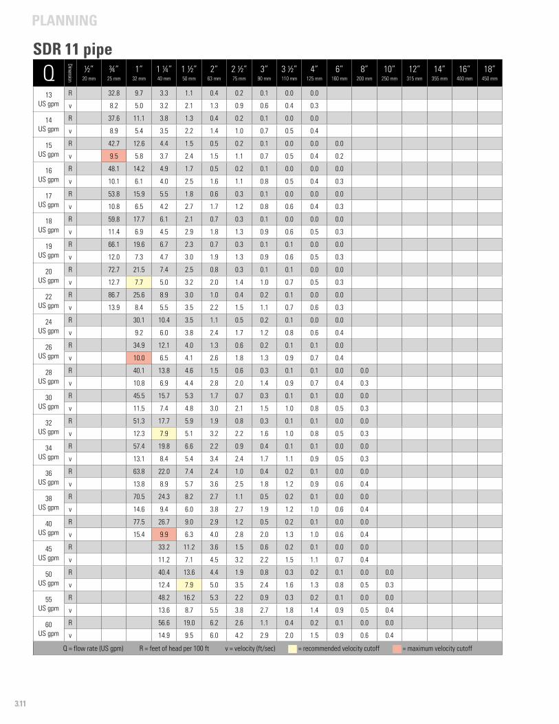
PLANNING
3.11
Q
Dimension
½”20 mm
¾”25 mm
1”32 mm
1 ¼”40 mm
1 ½”50 mm
2”63 mm
2 ½”75 mm
3”90 mm
3 ½”110 mm
4”125 mm
6”160 mm
8”200 mm
10”250 mm
12”315 mm
14”355 mm
16”400 mm
18”450 mm
13US gpm
R 32.8 9.7 3.3 1.1 0.4 0.2 0.1 0.0 0.0
v 8.2 5.0 3.2 2.1 1.3 0.9 0.6 0.4 0.3
14 US gpm
R 37.6 11.1 3.8 1.3 0.4 0.2 0.1 0.0 0.0
v 8.9 5.4 3.5 2.2 1.4 1.0 0.7 0.5 0.4
15US gpm
R 42.7 12.6 4.4 1.5 0.5 0.2 0.1 0.0 0.0 0.0
v 9.5 5.8 3.7 2.4 1.5 1.1 0.7 0.5 0.4 0.2
16US gpm
R 48.1 14.2 4.9 1.7 0.5 0.2 0.1 0.0 0.0 0.0
v 10.1 6.1 4.0 2.5 1.6 1.1 0.8 0.5 0.4 0.3
17US gpm
R 53.8 15.9 5.5 1.8 0.6 0.3 0.1 0.0 0.0 0.0
v 10.8 6.5 4.2 2.7 1.7 1.2 0.8 0.6 0.4 0.3
18US gpm
R 59.8 17.7 6.1 2.1 0.7 0.3 0.1 0.0 0.0 0.0
v 11.4 6.9 4.5 2.9 1.8 1.3 0.9 0.6 0.5 0.3
19US gpm
R 66.1 19.6 6.7 2.3 0.7 0.3 0.1 0.1 0.0 0.0
v 12.0 7.3 4.7 3.0 1.9 1.3 0.9 0.6 0.5 0.3
20US gpm
R 72.7 21.5 7.4 2.5 0.8 0.3 0.1 0.1 0.0 0.0
v 12.7 7.7 5.0 3.2 2.0 1.4 1.0 0.7 0.5 0.3
22US gpm
R 86.7 25.6 8.9 3.0 1.0 0.4 0.2 0.1 0.0 0.0
v 13.9 8.4 5.5 3.5 2.2 1.5 1.1 0.7 0.6 0.3
24US gpm
R 30.1 10.4 3.5 1.1 0.5 0.2 0.1 0.0 0.0
v 9.2 6.0 3.8 2.4 1.7 1.2 0.8 0.6 0.4
26US gpm
R 34.9 12.1 4.0 1.3 0.6 0.2 0.1 0.1 0.0
v 10.0 6.5 4.1 2.6 1.8 1.3 0.9 0.7 0.4
28US gpm
R 40.1 13.8 4.6 1.5 0.6 0.3 0.1 0.1 0.0 0.0
v 10.8 6.9 4.4 2.8 2.0 1.4 0.9 0.7 0.4 0.3
30US gpm
R 45.5 15.7 5.3 1.7 0.7 0.3 0.1 0.1 0.0 0.0
v 11.5 7.4 4.8 3.0 2.1 1.5 1.0 0.8 0.5 0.3
32US gpm
R 51.3 17.7 5.9 1.9 0.8 0.3 0.1 0.1 0.0 0.0
v 12.3 7.9 5.1 3.2 2.2 1.6 1.0 0.8 0.5 0.3
34US gpm
R 57.4 19.8 6.6 2.2 0.9 0.4 0.1 0.1 0.0 0.0
v 13.1 8.4 5.4 3.4 2.4 1.7 1.1 0.9 0.5 0.3
36US gpm
R 63.8 22.0 7.4 2.4 1.0 0.4 0.2 0.1 0.0 0.0
v 13.8 8.9 5.7 3.6 2.5 1.8 1.2 0.9 0.6 0.4
38US gpm
R 70.5 24.3 8.2 2.7 1.1 0.5 0.2 0.1 0.0 0.0
v 14.6 9.4 6.0 3.8 2.7 1.9 1.2 1.0 0.6 0.4
40US gpm
R 77.5 26.7 9.0 2.9 1.2 0.5 0.2 0.1 0.0 0.0
v 15.4 9.9 6.3 4.0 2.8 2.0 1.3 1.0 0.6 0.4
45US gpm
R 33.2 11.2 3.6 1.5 0.6 0.2 0.1 0.0 0.0
v 11.2 7.1 4.5 3.2 2.2 1.5 1.1 0.7 0.4
50US gpm
R 40.4 13.6 4.4 1.9 0.8 0.3 0.2 0.1 0.0 0.0
v 12.4 7.9 5.0 3.5 2.4 1.6 1.3 0.8 0.5 0.3
55US gpm
R 48.2 16.2 5.3 2.2 0.9 0.3 0.2 0.1 0.0 0.0
v 13.6 8.7 5.5 3.8 2.7 1.8 1.4 0.9 0.5 0.4
60US gpm
R 56.6 19.0 6.2 2.6 1.1 0.4 0.2 0.1 0.0 0.0
v 14.9 9.5 6.0 4.2 2.9 2.0 1.5 0.9 0.6 0.4
Q = flow rate (US gpm) R = feet of head per 100 ft v = velocity (ft/sec) - = recommended velocity cutoff - = maximum velocity cutoff
SDR 11 pipe
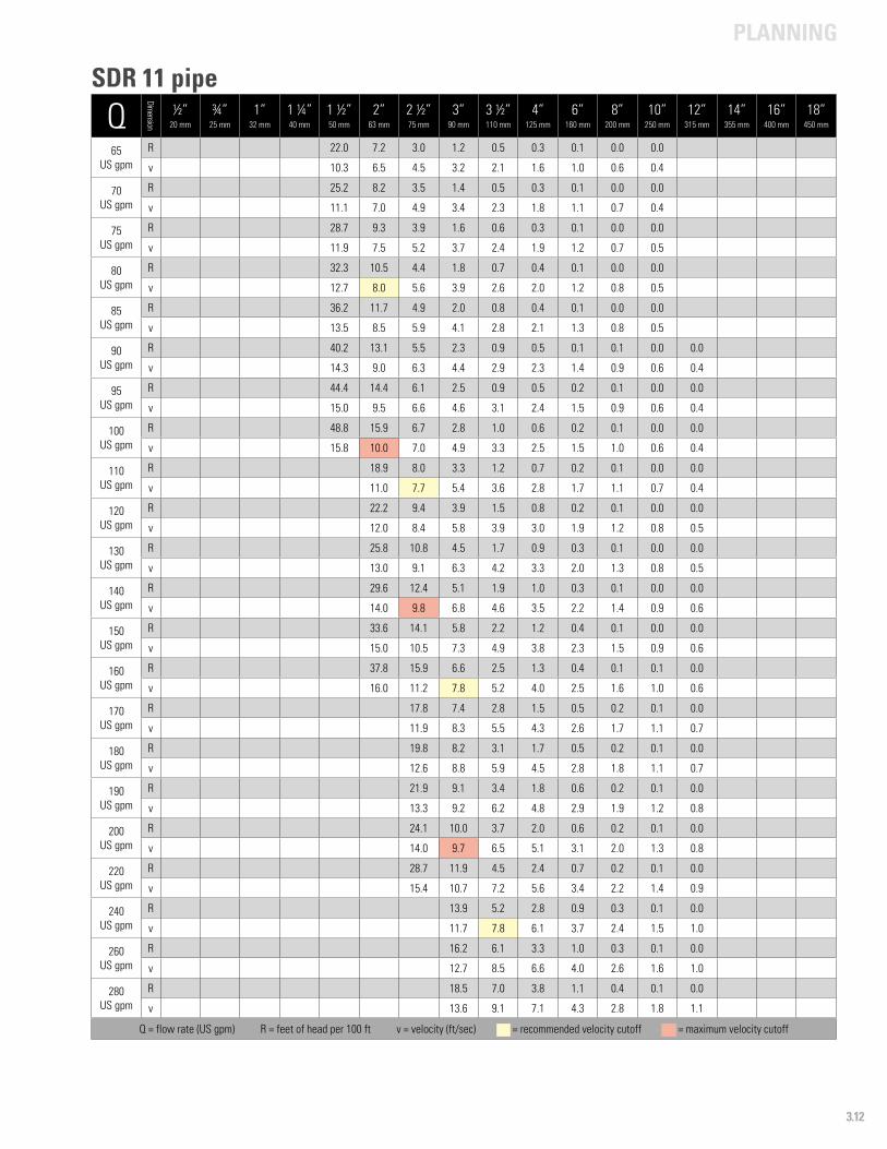
PLANNING
3.12
Q
Dimension
½”20 mm
¾”25 mm
1”32 mm
1 ¼”40 mm
1 ½”50 mm
2”63 mm
2 ½”75 mm
3”90 mm
3 ½”110 mm
4”125 mm
6”160 mm
8”200 mm
10”250 mm
12”315 mm
14”355 mm
16”400 mm
18”450 mm
65US gpm
R 22.0 7.2 3.0 1.2 0.5 0.3 0.1 0.0 0.0
v 10.3 6.5 4.5 3.2 2.1 1.6 1.0 0.6 0.4
70US gpm
R 25.2 8.2 3.5 1.4 0.5 0.3 0.1 0.0 0.0
v 11.1 7.0 4.9 3.4 2.3 1.8 1.1 0.7 0.4
75US gpm
R 28.7 9.3 3.9 1.6 0.6 0.3 0.1 0.0 0.0
v 11.9 7.5 5.2 3.7 2.4 1.9 1.2 0.7 0.5
80US gpm
R 32.3 10.5 4.4 1.8 0.7 0.4 0.1 0.0 0.0
v 12.7 8.0 5.6 3.9 2.6 2.0 1.2 0.8 0.5
85US gpm
R 36.2 11.7 4.9 2.0 0.8 0.4 0.1 0.0 0.0
v 13.5 8.5 5.9 4.1 2.8 2.1 1.3 0.8 0.5
90US gpm
R 40.2 13.1 5.5 2.3 0.9 0.5 0.1 0.1 0.0 0.0
v 14.3 9.0 6.3 4.4 2.9 2.3 1.4 0.9 0.6 0.4
95US gpm
R 44.4 14.4 6.1 2.5 0.9 0.5 0.2 0.1 0.0 0.0
v 15.0 9.5 6.6 4.6 3.1 2.4 1.5 0.9 0.6 0.4
100US gpm
R 48.8 15.9 6.7 2.8 1.0 0.6 0.2 0.1 0.0 0.0
v 15.8 10.0 7.0 4.9 3.3 2.5 1.5 1.0 0.6 0.4
110US gpm
R 18.9 8.0 3.3 1.2 0.7 0.2 0.1 0.0 0.0
v 11.0 7.7 5.4 3.6 2.8 1.7 1.1 0.7 0.4
120US gpm
R 22.2 9.4 3.9 1.5 0.8 0.2 0.1 0.0 0.0
v 12.0 8.4 5.8 3.9 3.0 1.9 1.2 0.8 0.5
130US gpm
R 25.8 10.8 4.5 1.7 0.9 0.3 0.1 0.0 0.0
v 13.0 9.1 6.3 4.2 3.3 2.0 1.3 0.8 0.5
140US gpm
R 29.6 12.4 5.1 1.9 1.0 0.3 0.1 0.0 0.0
v 14.0 9.8 6.8 4.6 3.5 2.2 1.4 0.9 0.6
150US gpm
R 33.6 14.1 5.8 2.2 1.2 0.4 0.1 0.0 0.0
v 15.0 10.5 7.3 4.9 3.8 2.3 1.5 0.9 0.6
160US gpm
R 37.8 15.9 6.6 2.5 1.3 0.4 0.1 0.1 0.0
v 16.0 11.2 7.8 5.2 4.0 2.5 1.6 1.0 0.6
170US gpm
R 17.8 7.4 2.8 1.5 0.5 0.2 0.1 0.0
v 11.9 8.3 5.5 4.3 2.6 1.7 1.1 0.7
180US gpm
R 19.8 8.2 3.1 1.7 0.5 0.2 0.1 0.0
v 12.6 8.8 5.9 4.5 2.8 1.8 1.1 0.7
190US gpm
R 21.9 9.1 3.4 1.8 0.6 0.2 0.1 0.0
v 13.3 9.2 6.2 4.8 2.9 1.9 1.2 0.8
200US gpm
R 24.1 10.0 3.7 2.0 0.6 0.2 0.1 0.0
v 14.0 9.7 6.5 5.1 3.1 2.0 1.3 0.8
220US gpm
R 28.7 11.9 4.5 2.4 0.7 0.2 0.1 0.0
v 15.4 10.7 7.2 5.6 3.4 2.2 1.4 0.9
240US gpm
R 13.9 5.2 2.8 0.9 0.3 0.1 0.0
v 11.7 7.8 6.1 3.7 2.4 1.5 1.0
260US gpm
R 16.2 6.1 3.3 1.0 0.3 0.1 0.0
v 12.7 8.5 6.6 4.0 2.6 1.6 1.0
280US gpm
R 18.5 7.0 3.8 1.1 0.4 0.1 0.0
v 13.6 9.1 7.1 4.3 2.8 1.8 1.1
Q = flow rate (US gpm) R = feet of head per 100 ft v = velocity (ft/sec) - = recommended velocity cutoff - = maximum velocity cutoff
SDR 11 pipe
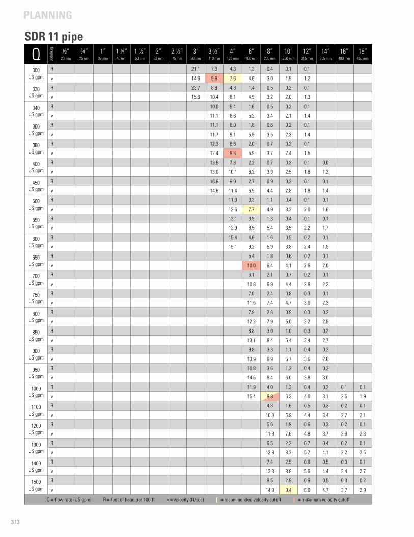
PLANNING
3.13
Q
Dimension
½”20 mm
¾”25 mm
1”32 mm
1 ¼”40 mm
1 ½”50 mm
2”63 mm
2 ½”75 mm
3”90 mm
3 ½”110 mm
4”125 mm
6”160 mm
8”200 mm
10”250 mm
12”315 mm
14”355 mm
16”400 mm
18”450 mm
300US gpm
R 21.1 7.9 4.3 1.3 0.4 0.1 0.1
v 14.6 9.8 7.6 4.6 3.0 1.9 1.2
320US gpm
R 23.7 8.9 4.8 1.4 0.5 0.2 0.1
v 15.6 10.4 8.1 4.9 3.2 2.0 1.3
340US gpm
R 10.0 5.4 1.6 0.5 0.2 0.1
v 11.1 8.6 5.2 3.4 2.1 1.4
360US gpm
R 11.1 6.0 1.8 0.6 0.2 0.1
v 11.7 9.1 5.5 3.5 2.3 1.4
380US gpm
R 12.3 6.6 2.0 0.7 0.2 0.1
v 12.4 9.6 5.9 3.7 2.4 1.5
400US gpm
R 13.5 7.3 2.2 0.7 0.3 0.1 0.0
v 13.0 10.1 6.2 3.9 2.5 1.6 1.2
450US gpm
R 16.8 9.0 2.7 0.9 0.3 0.1 0.1
v 14.6 11.4 6.9 4.4 2.8 1.8 1.4
500US gpm
R 11.0 3.3 1.1 0.4 0.1 0.1
v 12.6 7.7 4.9 3.2 2.0 1.6
550US gpm
R 13.1 3.9 1.3 0.4 0.1 0.1
v 13.9 8.5 5.4 3.5 2.2 1.7
600US gpm
R 15.4 4.6 1.6 0.5 0.2 0.1
v 15.1 9.2 5.9 3.8 2.4 1.9
650US gpm
R 5.4 1.8 0.6 0.2 0.1
v 10.0 6.4 4.1 2.6 2.0
700US gpm
R 6.1 2.1 0.7 0.2 0.1
v 10.8 6.9 4.4 2.8 2.2
750US gpm
R 7.0 2.4 0.8 0.3 0.1
v 11.6 7.4 4.7 3.0 2.3
800US gpm
R 7.9 2.6 0.9 0.3 0.2
v 12.3 7.9 5.0 3.2 2.5
850US gpm
R 8.8 3.0 1.0 0.3 0.2
v 13.1 8.4 5.4 3.4 2.7
900US gpm
R 9.8 3.3 1.1 0.4 0.2
v 13.9 8.9 5.7 3.6 2.8
950US gpm
R 10.8 3.6 1.2 0.4 0.2
v 14.6 9.4 6.0 3.8 3.0
1000US gpm
R 11.9 4.0 1.3 0.4 0.2 0.1 0.1
v 15.4 9.8 6.3 4.0 3.1 2.5 1.9
1100US gpm
R 4.8 1.6 0.5 0.3 0.2 0.1
v 10.8 6.9 4.4 3.4 2.7 2.1
1200US gpm
R 5.6 1.9 0.6 0.3 0.2 0.1
v 11.8 7.6 4.8 3.7 2.9 2.3
1300US gpm
R 6.5 2.2 0.7 0.4 0.2 0.1
v 12.8 8.2 5.2 4.1 3.2 2.5
1400US gpm
R 7.4 2.5 0.8 0.5 0.3 0.1
v 13.8 8.8 5.6 4.4 3.4 2.7
1500US gpm
R 8.5 2.9 0.9 0.5 0.3 0.2
v 14.8 9.4 6.0 4.7 3.7 2.9
Q = flow rate (US gpm) R = feet of head per 100 ft v = velocity (ft/sec) - = recommended velocity cutoff - = maximum velocity cutoff
SDR 11 pipe
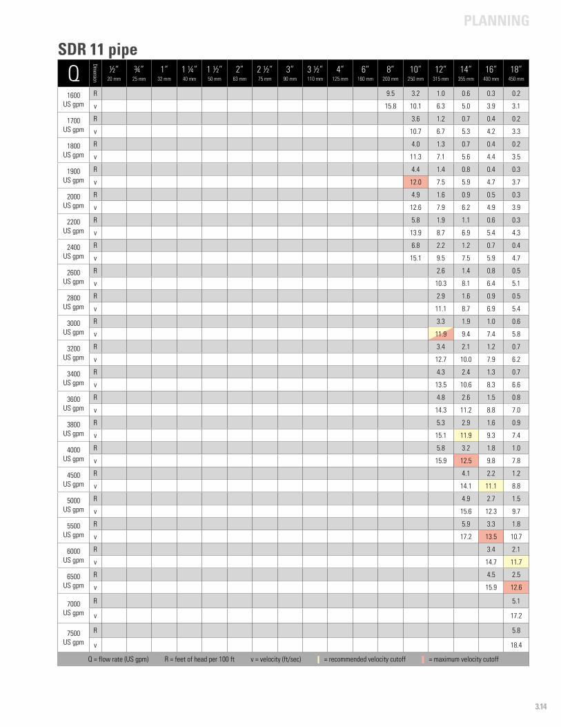
PLANNING
3.14
Q
Dimension
½”20 mm
¾”25 mm
1”32 mm
1 ¼”40 mm
1 ½”50 mm
2”63 mm
2 ½”75 mm
3”90 mm
3 ½”110 mm
4”125 mm
6”160 mm
8”200 mm
10”250 mm
12”315 mm
14”355 mm
16”400 mm
18”450 mm
1600US gpm
R 9.5 3.2 1.0 0.6 0.3 0.2
v 15.8 10.1 6.3 5.0 3.9 3.1
1700US gpm
R 3.6 1.2 0.7 0.4 0.2
v 10.7 6.7 5.3 4.2 3.3
1800US gpm
R 4.0 1.3 0.7 0.4 0.2
v 11.3 7.1 5.6 4.4 3.5
1900US gpm
R 4.4 1.4 0.8 0.4 0.3
v 12.0 7.5 5.9 4.7 3.7
2000US gpm
R 4.9 1.6 0.9 0.5 0.3
v 12.6 7.9 6.2 4.9 3.9
2200US gpm
R 5.8 1.9 1.1 0.6 0.3
v 13.9 8.7 6.9 5.4 4.3
2400US gpm
R 6.8 2.2 1.2 0.7 0.4
v 15.1 9.5 7.5 5.9 4.7
2600US gpm
R 2.6 1.4 0.8 0.5
v 10.3 8.1 6.4 5.1
2800US gpm
R 2.9 1.6 0.9 0.5
v 11.1 8.7 6.9 5.4
3000US gpm
R 3.3 1.9 1.0 0.6
v 11.9 9.4 7.4 5.8
3200US gpm
R 3.4 2.1 1.2 0.7
v 12.7 10.0 7.9 6.2
3400US gpm
R 4.3 2.4 1.3 0.7
v 13.5 10.6 8.3 6.6
3600US gpm
R 4.8 2.6 1.5 0.8
v 14.3 11.2 8.8 7.0
3800US gpm
R 5.3 2.9 1.6 0.9
v 15.1 11.9 9.3 7.4
4000US gpm
R 5.8 3.2 1.8 1.0
v 15.9 12.5 9.8 7.8
4500 US gpm
R 4.1 2.2 1.2
v 14.1 11.1 8.8
5000US gpm
R 4.9 2.7 1.5
v 15.6 12.3 9.7
5500 US gpm
R 5.9 3.3 1.8
v 17.2 13.5 10.7
6000US gpm
R 3.4 2.1
v 14.7 11.7
6500US gpm
R 4.5 2.5
v 15.9 12.6
7000US gpm
R 5.1
v 17.2
7500US gpm
R 5.8
v 18.4
Q = flow rate (US gpm) R = feet of head per 100 ft v = velocity (ft/sec) - = recommended velocity cutoff - = maximum velocity cutoff
SDR 11 pipe
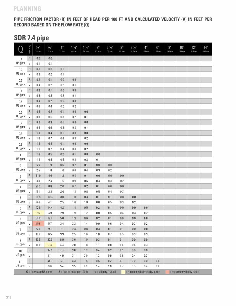
PLANNING
3.15
Q
Dimension
½”20 mm
¾”25 mm
1”32 mm
1 ¼”40 mm
1 ½”50 mm
2”63 mm
2 ½”75 mm
3”90 mm
3 ½”110 mm
4”125 mm
6”160 mm
8”200 mm
10”250 mm
12”315 mm
14”355 mm
0.1US gpm
R 0.0 0.0
v 0.1 0.1
0.2US gpm
R 0.1 0.0 0.0
v 0.3 0.2 0.1
0.3 US gpm
R 0.2 0.1 0.0 0.0
v 0.4 0.2 0.2 0.1
0.4 US gpm
R 0.3 0.1 0.0 0.0
v 0.5 0.3 0.2 0.1
0.5US gpm
R 0.4 0.2 0.0 0.0
v 0.6 0.4 0.2 0.2
0.6US gpm
R 0.6 0.2 0.1 0.0 0.0
v 0.8 0.5 0.3 0.2 0.1
0.7US gpm
R 0.8 0.3 0.1 0.0 0.0
v 0.9 0.6 0.3 0.2 0.1
0.8US gpm
R 1.0 0.4 0.1 0.0 0.0
v 1.0 0.7 0.4 0.3 0.2
0.9US gpm
R 1.3 0.4 0.1 0.0 0.0
v 1.1 0.7 0.4 0.3 0.2
1US gpm
R 1.6 0.5 0.2 0.1 0.0 0.0
v 1.3 0.8 0.5 0.3 0.2 0.1
2US gpm
R 5.6 1.9 0.6 0.2 0.1 0.0 0.0
v 2.5 1.6 1.0 0.6 0.4 0.3 0.2
3 US gpm
R 11.9 4.0 1.2 0.4 0.1 0.0 0.0 0.0
v 3.8 2.4 1.5 0.9 0.6 0.4 0.3 0.2
4US gpm
R 20.2 6.8 2.0 0.7 0.2 0.1 0.0 0.0
v 5.1 3.3 2.0 1.3 0.8 0.5 0.4 0.3
5US gpm
R 30.5 10.3 3.0 1.0 0.3 0.1 0.1 0.0 0.0
v 6.4 4.1 2.5 1.6 1.0 0.6 0.5 0.3 0.2
6US gpm
R 42.8 14.4 4.2 1.4 0.5 0.2 0.1 0.0 0.0 0.0
v 7.6 4.9 2.9 1.9 1.2 0.8 0.5 0.4 0.3 0.2
7US gpm
R 56.9 19.2 5.6 1.9 0.6 0.2 0.1 0.0 0.0 0.0
v 8.9 5.7 3.4 2.2 1.4 0.9 0.6 0.4 0.3 0.2
8US gpm
R 72.8 24.6 7.1 2.4 0.8 0.3 0.1 0.1 0.0 0.0
v 10.2 6.5 3.9 2.5 1.6 1.0 0.7 0.5 0.3 0.3
9US gpm
R 90.5 30.5 8.9 3.0 1.0 0.3 0.1 0.1 0.0 0.0
v 11.4 7.3 4.4 2.8 1.8 1.1 0.8 0.6 0.4 0.3
10US gpm
R 37.1 10.8 3.6 1.2 0.4 0.2 0.1 0.0 0.0
v 8.1 4.9 3.1 2.0 1.3 0.9 0.6 0.4 0.3
11US gpm
R 44.3 12.9 4.3 1.5 0.5 0.2 0.1 0.0 0.0 0.0
v 9.0 5.4 3.5 2.2 1.4 1.0 0.7 0.5 0.4 0.2
Q = flow rate (US gpm) R = feet of head per 100 ft v = velocity (ft/sec) - = recommended velocity cutoff - = maximum velocity cutoff
PIPE FRICTION FACTOR (R) IN FEET OF HEAD PER 100 FT AND CALCULATED VELOCITY (V) IN FEET PER SECOND BASED ON THE FLOW RATE (Q)
SDR 7.4 pipe
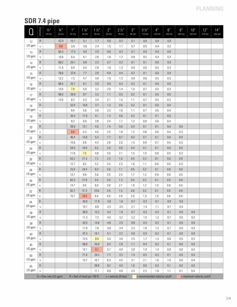
PLANNING
3.16
Q
Dimension
½”20 mm
¾”25 mm
1”32 mm
1 ¼”40 mm
1 ½”50 mm
2”63 mm
2 ½”75 mm
3”90 mm
3 ½”110 mm
4”125 mm
6”160 mm
8”200 mm
10”250 mm
12”315 mm
14”355 mm
12US gpm
R 52.0 15.1 5.1 1.7 0.6 0.2 0.1 0.0 0.0 0.0
v 9.8 5.9 3.8 2.4 1.5 1.1 0.7 0.5 0.4 0.2
13US gpm
R 60.3 17.5 5.9 2.0 0.6 0.3 0.1 0.0 0.0 0.0
v 10.6 6.4 4.1 2.6 1.6 1.2 0.8 0.5 0.4 0.3
14 US gpm
R 69.2 20.1 6.8 2.3 0.7 0.3 0.1 0.1 0.0 0.0
v 11.4 6.9 4.4 2.8 1.8 1.3 0.9 0.6 0.5 0.3
15US gpm
R 78.6 22.8 7.7 2.6 0.8 0.4 0.2 0.1 0.0 0.0
v 12.2 7.3 4.7 3.0 1.9 1.3 0.9 0.6 0.5 0.3
16US gpm
R 88.5 25.7 8.7 3.0 0.9 0.4 0.2 0.1 0.0 0.0
v 13.0 7.8 5.0 3.2 2.0 1.4 1.0 0.7 0.5 0.3
17US gpm
R 99.0 28.8 9.7 3.3 1.1 0.5 0.2 0.1 0.0 0.0
v 13.8 8.3 5.3 3.4 2.1 1.5 1.1 0.7 0.5 0.3
18US gpm
R 32.0 10.8 3.7 1.2 0.5 0.2 0.1 0.0 0.0
v 8.8 5.6 3.6 2.3 1.6 1.1 0.7 0.6 0.4
19US gpm
R 35.4 11.9 4.1 1.3 0.6 0.2 0.1 0.1 0.0
v 9.3 6.0 3.8 2.4 1.7 1.2 0.8 0.6 0.4
20US gpm
R 38.9 13.1 4.5 1.4 0.6 0.3 0.1 0.1 0.0 0.0
v 9.8 6.3 4.0 2.5 1.8 1.2 0.8 0.6 0.4 0.3
22US gpm
R 46.4 15.6 5.3 1.7 0.7 0.3 0.1 0.1 0.0 0.0
v 10.8 6.9 4.4 2.8 2.0 1.4 0.9 0.7 0.4 0.3
24US gpm
R 54.5 18.4 6.2 2.0 0.9 0.4 0.1 0.1 0.0 0.0
v 11.8 7.5 4.8 3.0 2.1 1.5 1.0 0.8 0.5 0.3
26US gpm
R 63.2 21.3 7.2 2.3 1.0 0.4 0.2 0.1 0.0 0.0
v 12.7 8.2 5.2 3.3 2.3 1.6 1.1 0.8 0.5 0.3
28US gpm
R 72.4 24.4 8.3 2.6 1.1 0.5 0.2 0.1 0.0 0.0
v 13.7 8.8 5.6 3.5 2.5 1.7 1.2 0.9 0.6 0.4
30US gpm
R 82.3 27.8 9.4 3.0 1.3 0.5 0.2 0.1 0.0 0.0
v 14.7 9.4 6.0 3.8 2.7 1.9 1.2 1.0 0.6 0.4
32US gpm
R 92.7 31.3 10.6 3.4 1.5 0.6 0.2 0.1 0.0 0.0
v 15.7 10.0 6.4 4.0 2.9 2.0 1.3 1.0 0.6 0.4
34US gpm
R 35.0 11.9 3.8 1.6 0.7 0.3 0.1 0.0 0.0
v 10.7 6.8 4.3 3.0 2.1 1.4 1.1 0.7 0.4
36US gpm
R 38.9 13.2 4.2 1.8 0.7 0.3 0.2 0.1 0.0 0.0
v 11.3 7.2 4.5 3.2 2.2 1.5 1.2 0.7 0.5 0.3
38US gpm
R 43.0 14.6 4.6 2.0 0.8 0.3 0.2 0.1 0.0 0.0
v 11.9 7.6 4.8 3.4 2.3 1.6 1.2 0.7 0.5 0.3
40US gpm
R 47.3 16.1 5.1 2.2 0.9 0.3 0.2 0.1 0.0 0.0
v 12.5 8.0 5.0 3.6 2.5 1.7 1.3 0.8 0.5 0.3
45US gpm
R 58.8 20.0 6.4 2.8 1.1 0.4 0.2 0.1 0.0 0.0
v 14.1 9.1 5.7 4.0 2.8 1.9 1.4 0.9 0.6 0.4
50US gpm
R 71.4 24.3 7.7 3.3 1.4 0.5 0.3 0.1 0.0 0.0
v 15.7 10.1 6.3 4.5 3.1 2.1 1.6 1.0 0.6 0.4
55US gpm
R 28.9 9.2 4.0 1.6 0.6 0.3 0.1 0.0 0.0
v 11.1 6.9 4.9 3.4 2.3 1.8 1.1 0.7 0.4
Q = flow rate (US gpm) R = feet of head per 100 ft v = velocity (ft/sec) - = recommended velocity cutoff - = maximum velocity cutoff
SDR 7.4 pipe
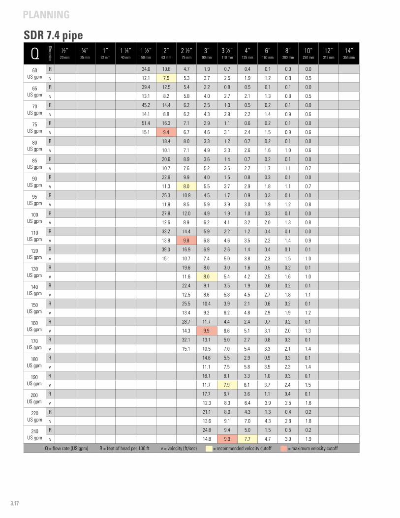
PLANNING
3.17
Q
Dimension
½”20 mm
¾”25 mm
1”32 mm
1 ¼”40 mm
1 ½”50 mm
2”63 mm
2 ½”75 mm
3”90 mm
3 ½”110 mm
4”125 mm
6”160 mm
8”200 mm
10”250 mm
12”315 mm
14”355 mm
60US gpm
R 34.0 10.8 4.7 1.9 0.7 0.4 0.1 0.0 0.0
v 12.1 7.5 5.3 3.7 2.5 1.9 1.2 0.8 0.5
65US gpm
R 39.4 12.5 5.4 2.2 0.8 0.5 0.1 0.1 0.0
v 13.1 8.2 5.8 4.0 2.7 2.1 1.3 0.8 0.5
70US gpm
R 45.2 14.4 6.2 2.5 1.0 0.5 0.2 0.1 0.0
v 14.1 8.8 6.2 4.3 2.9 2.2 1.4 0.9 0.6
75US gpm
R 51.4 16.3 7.1 2.9 1.1 0.6 0.2 0.1 0.0
v 15.1 9.4 6.7 4.6 3.1 2.4 1.5 0.9 0.6
80US gpm
R 18.4 8.0 3.3 1.2 0.7 0.2 0.1 0.0
v 10.1 7.1 4.9 3.3 2.6 1.6 1.0 0.6
85US gpm
R 20.6 8.9 3.6 1.4 0.7 0.2 0.1 0.0
v 10.7 7.6 5.2 3.5 2.7 1.7 1.1 0.7
90US gpm
R 22.9 9.9 4.0 1.5 0.8 0.3 0.1 0.0
v 11.3 8.0 5.5 3.7 2.9 1.8 1.1 0.7
95US gpm
R 25.3 10.9 4.5 1.7 0.9 0.3 0.1 0.0
v 11.9 8.5 5.9 3.9 3.0 1.9 1.2 0.8
100US gpm
R 27.8 12.0 4.9 1.9 1.0 0.3 0.1 0.0
v 12.6 8.9 6.2 4.1 3.2 2.0 1.3 0.8
110US gpm
R 33.2 14.4 5.9 2.2 1.2 0.4 0.1 0.0
v 13.8 9.8 6.8 4.6 3.5 2.2 1.4 0.9
120US gpm
R 39.0 16.9 6.9 2.6 1.4 0.4 0.1 0.1
v 15.1 10.7 7.4 5.0 3.8 2.3 1.5 1.0
130US gpm
R 19.6 8.0 3.0 1.6 0.5 0.2 0.1
v 11.6 8.0 5.4 4.2 2.5 1.6 1.0
140US gpm
R 22.4 9.1 3.5 1.9 0.6 0.2 0.1
v 12.5 8.6 5.8 4.5 2.7 1.8 1.1
150US gpm
R 25.5 10.4 3.9 2.1 0.6 0.2 0.1
v 13.4 9.2 6.2 4.8 2.9 1.9 1.2
160US gpm
R 28.7 11.7 4.4 2.4 0.7 0.2 0.1
v 14.3 9.9 6.6 5.1 3.1 2.0 1.3
170US gpm
R 32.1 13.1 5.0 2.7 0.8 0.3 0.1
v 15.1 10.5 7.0 5.4 3.3 2.1 1.4
180US gpm
R 14.6 5.5 2.9 0.9 0.3 0.1
v 11.1 7.5 5.8 3.5 2.3 1.4
190US gpm
R 16.1 6.1 3.3 1.0 0.3 0.1
v 11.7 7.9 6.1 3.7 2.4 1.5
200US gpm
R 17.7 6.7 3.6 1.1 0.4 0.1
v 12.3 8.3 6.4 3.9 2.5 1.6
220US gpm
R 21.1 8.0 4.3 1.3 0.4 0.2
v 13.6 9.1 7.0 4.3 2.8 1.8
240US gpm
R 24.8 9.4 5.0 1.5 0.5 0.2
v 14.8 9.9 7.7 4.7 3.0 1.9
Q = flow rate (US gpm) R = feet of head per 100 ft v = velocity (ft/sec) - = recommended velocity cutoff - = maximum velocity cutoff
SDR 7.4 pipe
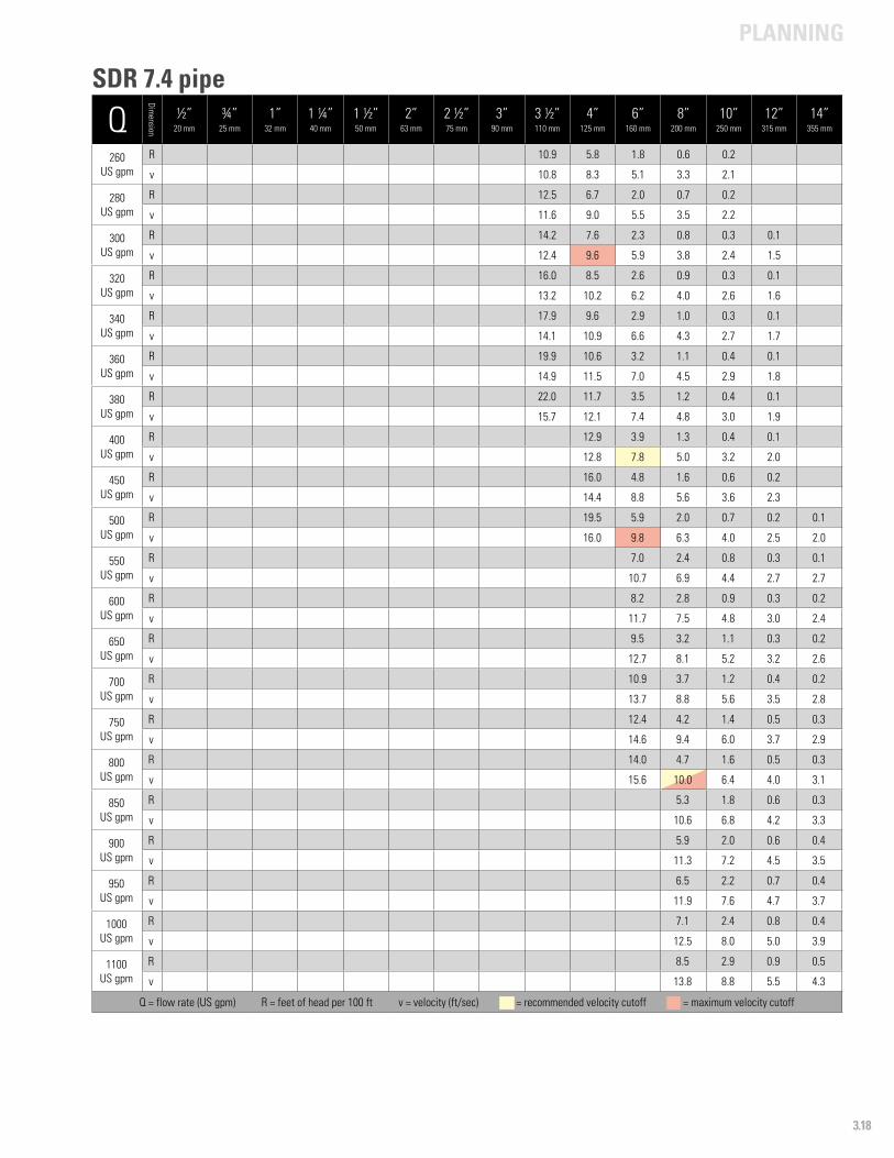
PLANNING
3.18
Q
Dimension
½”20 mm
¾”25 mm
1”32 mm
1 ¼”40 mm
1 ½”50 mm
2”63 mm
2 ½”75 mm
3”90 mm
3 ½”110 mm
4”125 mm
6”160 mm
8”200 mm
10”250 mm
12”315 mm
14”355 mm
260US gpm
R 10.9 5.8 1.8 0.6 0.2
v 10.8 8.3 5.1 3.3 2.1
280US gpm
R 12.5 6.7 2.0 0.7 0.2
v 11.6 9.0 5.5 3.5 2.2
300US gpm
R 14.2 7.6 2.3 0.8 0.3 0.1
v 12.4 9.6 5.9 3.8 2.4 1.5
320US gpm
R 16.0 8.5 2.6 0.9 0.3 0.1
v 13.2 10.2 6.2 4.0 2.6 1.6
340US gpm
R 17.9 9.6 2.9 1.0 0.3 0.1
v 14.1 10.9 6.6 4.3 2.7 1.7
360US gpm
R 19.9 10.6 3.2 1.1 0.4 0.1
v 14.9 11.5 7.0 4.5 2.9 1.8
380US gpm
R 22.0 11.7 3.5 1.2 0.4 0.1
v 15.7 12.1 7.4 4.8 3.0 1.9
400US gpm
R 12.9 3.9 1.3 0.4 0.1
v 12.8 7.8 5.0 3.2 2.0
450US gpm
R 16.0 4.8 1.6 0.6 0.2
v 14.4 8.8 5.6 3.6 2.3
500US gpm
R 19.5 5.9 2.0 0.7 0.2 0.1
v 16.0 9.8 6.3 4.0 2.5 2.0
550US gpm
R 7.0 2.4 0.8 0.3 0.1
v 10.7 6.9 4.4 2.7 2.7
600US gpm
R 8.2 2.8 0.9 0.3 0.2
v 11.7 7.5 4.8 3.0 2.4
650US gpm
R 9.5 3.2 1.1 0.3 0.2
v 12.7 8.1 5.2 3.2 2.6
700US gpm
R 10.9 3.7 1.2 0.4 0.2
v 13.7 8.8 5.6 3.5 2.8
750US gpm
R 12.4 4.2 1.4 0.5 0.3
v 14.6 9.4 6.0 3.7 2.9
800US gpm
R 14.0 4.7 1.6 0.5 0.3
v 15.6 10.0 6.4 4.0 3.1
850US gpm
R 5.3 1.8 0.6 0.3
v 10.6 6.8 4.2 3.3
900US gpm
R 5.9 2.0 0.6 0.4
v 11.3 7.2 4.5 3.5
950US gpm
R 6.5 2.2 0.7 0.4
v 11.9 7.6 4.7 3.7
1000US gpm
R 7.1 2.4 0.8 0.4
v 12.5 8.0 5.0 3.9
1100US gpm
R 8.5 2.9 0.9 0.5
v 13.8 8.8 5.5 4.3
Q = flow rate (US gpm) R = feet of head per 100 ft v = velocity (ft/sec) - = recommended velocity cutoff - = maximum velocity cutoff
SDR 7.4 pipe
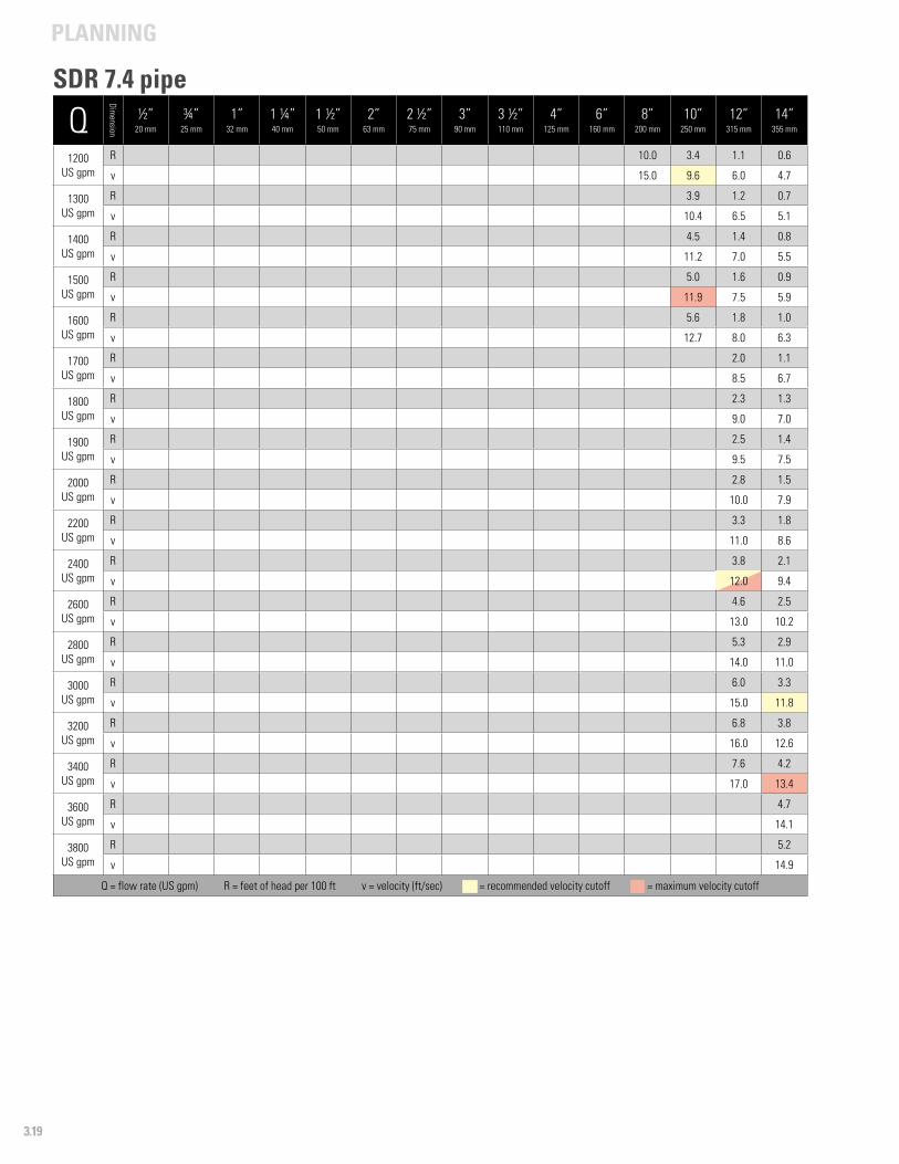
PLANNING
3.19
Q
Dimension
½”20 mm
¾”25 mm
1”32 mm
1 ¼”40 mm
1 ½”50 mm
2”63 mm
2 ½”75 mm
3”90 mm
3 ½”110 mm
4”125 mm
6”160 mm
8”200 mm
10”250 mm
12”315 mm
14”355 mm
1200US gpm
R 10.0 3.4 1.1 0.6
v 15.0 9.6 6.0 4.7
1300US gpm
R 3.9 1.2 0.7
v 10.4 6.5 5.1
1400US gpm
R 4.5 1.4 0.8
v 11.2 7.0 5.5
1500US gpm
R 5.0 1.6 0.9
v 11.9 7.5 5.9
1600US gpm
R 5.6 1.8 1.0
v 12.7 8.0 6.3
1700US gpm
R 2.0 1.1
v 8.5 6.7
1800US gpm
R 2.3 1.3
v 9.0 7.0
1900US gpm
R 2.5 1.4
v 9.5 7.5
2000US gpm
R 2.8 1.5
v 10.0 7.9
2200US gpm
R 3.3 1.8
v 11.0 8.6
2400US gpm
R 3.8 2.1
v 12.0 9.4
2600US gpm
R 4.6 2.5
v 13.0 10.2
2800US gpm
R 5.3 2.9
v 14.0 11.0
3000US gpm
R 6.0 3.3
v 15.0 11.8
3200US gpm
R 6.8 3.8
v 16.0 12.6
3400US gpm
R 7.6 4.2
v 17.0 13.4
3600US gpm
R 4.7
v 14.1
3800US gpm
R 5.2
v 14.9
Q = flow rate (US gpm) R = feet of head per 100 ft v = velocity (ft/sec) - = recommended velocity cutoff - = maximum velocity cutoff
SDR 7.4 pipe
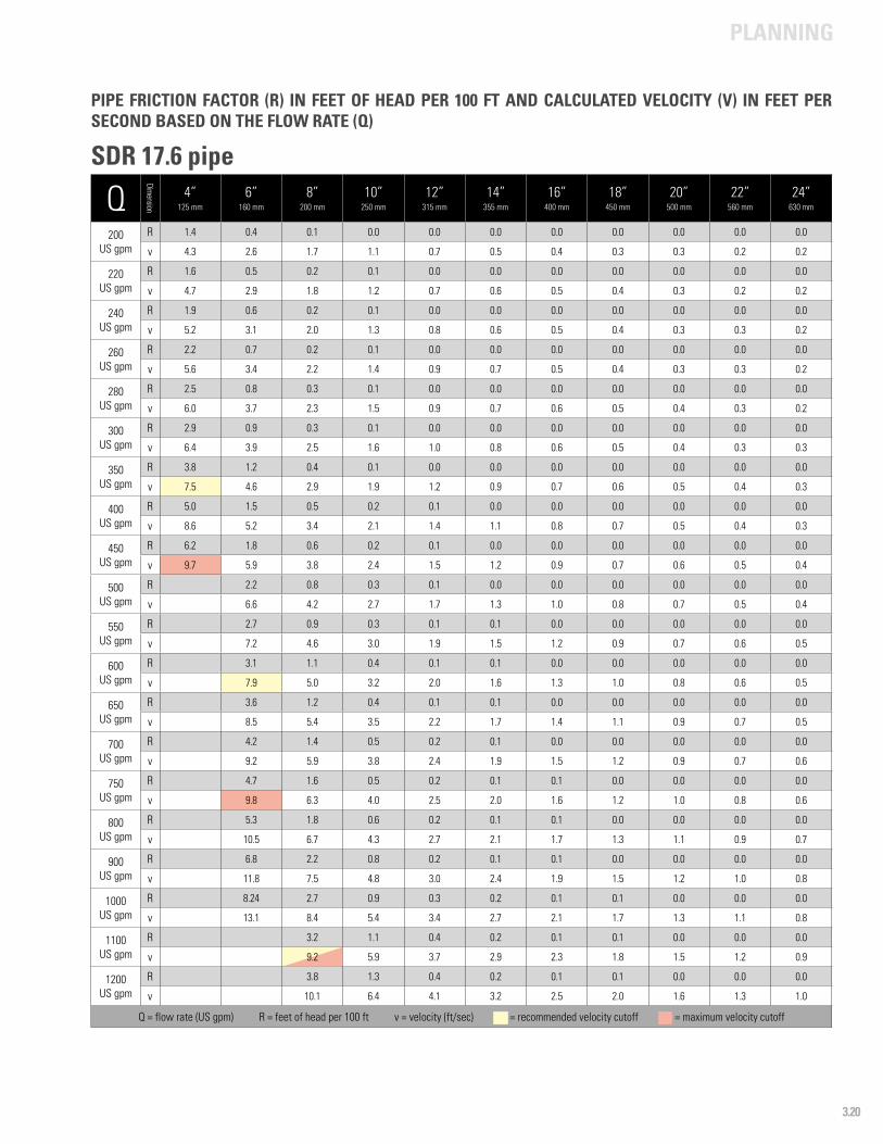
PLANNING
3.20
Q
Dimension
4”125 mm
6”160 mm
8”200 mm
10”250 mm
12”315 mm
14”355 mm
16”400 mm
18”450 mm
20”500 mm
22”560 mm
24”630 mm
200US gpm
R 1.4 0.4 0.1 0.0 0.0 0.0 0.0 0.0 0.0 0.0 0.0
v 4.3 2.6 1.7 1.1 0.7 0.5 0.4 0.3 0.3 0.2 0.2
220US gpm
R 1.6 0.5 0.2 0.1 0.0 0.0 0.0 0.0 0.0 0.0 0.0
v 4.7 2.9 1.8 1.2 0.7 0.6 0.5 0.4 0.3 0.2 0.2
240US gpm
R 1.9 0.6 0.2 0.1 0.0 0.0 0.0 0.0 0.0 0.0 0.0
v 5.2 3.1 2.0 1.3 0.8 0.6 0.5 0.4 0.3 0.3 0.2
260US gpm
R 2.2 0.7 0.2 0.1 0.0 0.0 0.0 0.0 0.0 0.0 0.0
v 5.6 3.4 2.2 1.4 0.9 0.7 0.5 0.4 0.3 0.3 0.2
280US gpm
R 2.5 0.8 0.3 0.1 0.0 0.0 0.0 0.0 0.0 0.0 0.0
v 6.0 3.7 2.3 1.5 0.9 0.7 0.6 0.5 0.4 0.3 0.2
300US gpm
R 2.9 0.9 0.3 0.1 0.0 0.0 0.0 0.0 0.0 0.0 0.0
v 6.4 3.9 2.5 1.6 1.0 0.8 0.6 0.5 0.4 0.3 0.3
350US gpm
R 3.8 1.2 0.4 0.1 0.0 0.0 0.0 0.0 0.0 0.0 0.0
v 7.5 4.6 2.9 1.9 1.2 0.9 0.7 0.6 0.5 0.4 0.3
400US gpm
R 5.0 1.5 0.5 0.2 0.1 0.0 0.0 0.0 0.0 0.0 0.0
v 8.6 5.2 3.4 2.1 1.4 1.1 0.8 0.7 0.5 0.4 0.3
450US gpm
R 6.2 1.8 0.6 0.2 0.1 0.0 0.0 0.0 0.0 0.0 0.0
v 9.7 5.9 3.8 2.4 1.5 1.2 0.9 0.7 0.6 0.5 0.4
500US gpm
R 2.2 0.8 0.3 0.1 0.0 0.0 0.0 0.0 0.0 0.0
v 6.6 4.2 2.7 1.7 1.3 1.0 0.8 0.7 0.5 0.4
550US gpm
R 2.7 0.9 0.3 0.1 0.1 0.0 0.0 0.0 0.0 0.0
v 7.2 4.6 3.0 1.9 1.5 1.2 0.9 0.7 0.6 0.5
600 US gpm
R 3.1 1.1 0.4 0.1 0.1 0.0 0.0 0.0 0.0 0.0
v 7.9 5.0 3.2 2.0 1.6 1.3 1.0 0.8 0.6 0.5
650 US gpm
R 3.6 1.2 0.4 0.1 0.1 0.0 0.0 0.0 0.0 0.0
v 8.5 5.4 3.5 2.2 1.7 1.4 1.1 0.9 0.7 0.5
700US gpm
R 4.2 1.4 0.5 0.2 0.1 0.0 0.0 0.0 0.0 0.0
v 9.2 5.9 3.8 2.4 1.9 1.5 1.2 0.9 0.7 0.6
750US gpm
R 4.7 1.6 0.5 0.2 0.1 0.1 0.0 0.0 0.0 0.0
v 9.8 6.3 4.0 2.5 2.0 1.6 1.2 1.0 0.8 0.6
800US gpm
R 5.3 1.8 0.6 0.2 0.1 0.1 0.0 0.0 0.0 0.0
v 10.5 6.7 4.3 2.7 2.1 1.7 1.3 1.1 0.9 0.7
900US gpm
R 6.8 2.2 0.8 0.2 0.1 0.1 0.0 0.0 0.0 0.0
v 11.8 7.5 4.8 3.0 2.4 1.9 1.5 1.2 1.0 0.8
1000US gpm
R 8.24 2.7 0.9 0.3 0.2 0.1 0.1 0.0 0.0 0.0
v 13.1 8.4 5.4 3.4 2.7 2.1 1.7 1.3 1.1 0.8
1100US gpm
R 3.2 1.1 0.4 0.2 0.1 0.1 0.0 0.0 0.0
v 9.2 5.9 3.7 2.9 2.3 1.8 1.5 1.2 0.9
1200US gpm
R 3.8 1.3 0.4 0.2 0.1 0.1 0.0 0.0 0.0
v 10.1 6.4 4.1 3.2 2.5 2.0 1.6 1.3 1.0
Q = flow rate (US gpm) R = feet of head per 100 ft v = velocity (ft/sec) - = recommended velocity cutoff - = maximum velocity cutoff
PIPE FRICTION FACTOR (R) IN FEET OF HEAD PER 100 FT AND CALCULATED VELOCITY (V) IN FEET PER SECOND BASED ON THE FLOW RATE (Q)
SDR 17.6 pipe
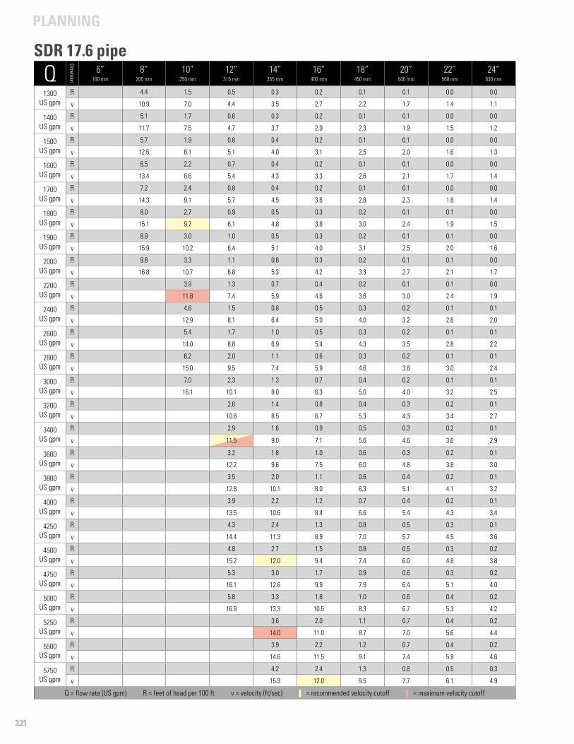
PLANNING
3.21
Q
Dimension
6”160 mm
8”200 mm
10”250 mm
12”315 mm
14”355 mm
16”400 mm
18”450 mm
20”500 mm
22”560 mm
24”630 mm
1300 US gpm
R 4.4 1.5 0.5 0.3 0.2 0.1 0.1 0.0 0.0
v 10.9 7.0 4.4 3.5 2.7 2.2 1.7 1.4 1.1
1400US gpm
R 5.1 1.7 0.6 0.3 0.2 0.1 0.1 0.0 0.0
v 11.7 7.5 4.7 3.7 2.9 2.3 1.9 1.5 1.2
1500US gpm
R 5.7 1.9 0.6 0.4 0.2 0.1 0.1 0.0 0.0
v 12.6 8.1 5.1 4.0 3.1 2.5 2.0 1.6 1.3
1600US gpm
R 6.5 2.2 0.7 0.4 0.2 0.1 0.1 0.0 0.0
v 13.4 8.6 5.4 4.3 3.3 2.6 2.1 1.7 1.4
1700US gpm
R 7.2 2.4 0.8 0.4 0.2 0.1 0.1 0.0 0.0
v 14.3 9.1 5.7 4.5 3.6 2.8 2.3 1.8 1.4
1800US gpm
R 8.0 2.7 0.9 0.5 0.3 0.2 0.1 0.1 0.0
v 15.1 9.7 6.1 4.8 3.8 3.0 2.4 1.9 1.5
1900US gpm
R 8.9 3.0 1.0 0.5 0.3 0.2 0.1 0.1 0.0
v 15.9 10.2 6.4 5.1 4.0 3.1 2.5 2.0 1.6
2000US gpm
R 9.8 3.3 1.1 0.6 0.3 0.2 0.1 0.1 0.0
v 16.8 10.7 6.8 5.3 4.2 3.3 2.7 2.1 1.7
2200US gpm
R 3.9 1.3 0.7 0.4 0.2 0.1 0.1 0.0
v 11.8 7.4 5.9 4.6 3.6 3.0 2.4 1.9
2400US gpm
R 4.6 1.5 0.8 0.5 0.3 0.2 0.1 0.1
v 12.9 8.1 6.4 5.0 4.0 3.2 2.6 2.0
2600US gpm
R 5.4 1.7 1.0 0.5 0.3 0.2 0.1 0.1
v 14.0 8.8 6.9 5.4 4.3 3.5 2.8 2.2
2800US gpm
R 6.2 2.0 1.1 0.6 0.3 0.2 0.1 0.1
v 15.0 9.5 7.4 5.9 4.6 3.8 3.0 2.4
3000 US gpm
R 7.0 2.3 1.3 0.7 0.4 0.2 0.1 0.1
v 16.1 10.1 8.0 6.3 5.0 4.0 3.2 2.5
3200 US gpm
R 2.6 1.4 0.8 0.4 0.3 0.2 0.1
v 10.8 8.5 6.7 5.3 4.3 3.4 2.7
3400US gpm
R 2.9 1.6 0.9 0.5 0.3 0.2 0.1
v 11.5 9.0 7.1 5.6 4.6 3.6 2.9
3600US gpm
R 3.2 1.8 1.0 0.6 0.3 0.2 0.1
v 12.2 9.6 7.5 6.0 4.8 3.8 3.0
3800US gpm
R 3.5 2.0 1.1 0.6 0.4 0.2 0.1
v 12.8 10.1 8.0 6.3 5.1 4.1 3.2
4000US gpm
R 3.9 2.2 1.2 0.7 0.4 0.2 0.1
v 13.5 10.6 8.4 6.6 5.4 4.3 3.4
4250US gpm
R 4.3 2.4 1.3 0.8 0.5 0.3 0.1
v 14.4 11.3 8.9 7.0 5.7 4.5 3.6
4500US gpm
R 4.8 2.7 1.5 0.8 0.5 0.3 0.2
v 15.2 12.0 9.4 7.4 6.0 4.8 3.8
4750US gpm
R 5.3 3.0 1.7 0.9 0.6 0.3 0.2
v 16.1 12.6 9.9 7.9 6.4 5.1 4.0
5000 US gpm
R 5.8 3.3 1.8 1.0 0.6 0.4 0.2
v 16.9 13.3 10.5 8.3 6.7 5.3 4.2
5250 US gpm
R 3.6 2.0 1.1 0.7 0.4 0.2
v 14.0 11.0 8.7 7.0 5.6 4.4
5500US gpm
R 3.9 2.2 1.2 0.7 0.4 0.2
v 14.6 11.5 9.1 7.4 5.9 4.6
5750US gpm
R 4.2 2.4 1.3 0.8 0.5 0.3
v 15.3 12.0 9.5 7.7 6.1 4.9
Q = flow rate (US gpm) R = feet of head per 100 ft v = velocity (ft/sec) - = recommended velocity cutoff - = maximum velocity cutoff
SDR 17.6 pipe
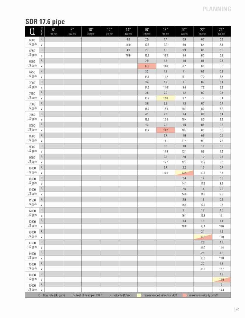
PLANNING
3.22
Q
Dimension
6”160 mm
8”200 mm
10”250 mm
12”315 mm
14”355 mm
16”400 mm
18”450 mm
20”500 mm
22”560 mm
24”630 mm
6000US gpm
R 4.6 2.5 1.4 0.9 0.5 0.3
v 16.0 12.6 9.9 8.0 6.4 5.1
6250US gpm
R 4.9 2.7 1.5 0.9 0.5 0.3
v 16.6 13.1 10.3 8.4 6.7 5.3
6500US gpm
R 2.9 1.7 1.0 0.6 0.3
v 13.6 10.8 8.7 6.9 5.5
6750US gpm
R 3.2 1.8 1.1 0.6 0.3
v 14.1 11.2 9.1 7.2 5.7
7000US gpm
R 3.4 1.9 1.1 0.7 0.4
v 14.6 11.6 9.4 7.5 5.9
7250US gpm
R 3.6 2.0 1.2 0.7 0.4
v 15.2 12.0 9.7 7.7 6.1
7500US gpm
R 3.8 2.2 1.3 0.7 0.4
v 15.7 12.4 10.1 8.0 6.3
7750US gpm
R 4.1 2.3 1.4 0.8 0.4
v 16.2 12.8 10.4 8.3 6.5
8000US gpm
R 4.3 2.4 1.5 0.8 0.5
v 16.7 13.2 10.7 8.5 6.8
8500US gpm
R 2.7 1.6 0.9 0.5
v 14.1 11.4 9.1 7.2
9000US gpm
R 3.0 1.8 1.0 0.6
v 14.9 12.1 9.6 7.6
9500 US gpm
R 3.3 2.0 1.2 0.7
v 15.7 12.7 10.2 8.0
10000 US gpm
R 3.7 2.2 1.3 0.7
v 16.5 13.4 10.7 8.4
10500US gpm
R 2.4 1.4 0.8
v 14.1 11.2 8.9
11000US gpm
R 2.6 1.5 0.9
v 14.8 11.8 9.3
11500US gpm
R 2.9 1.6 0.9
v 15.4 12.3 9.7
12000US gpm
R 3.1 1.8 1.0
v 16.1 12.8 10.1
12500US gpm
R 3.3 1.9 1.1
v 16.8 13.4 10.6
13000US gpm
R 2.1 1.2
v 13.9 11.0
13500US gpm
R 2.2 1.3
v 14.4 11.4
14000 US gpm
R 2.4 1.3
v 15.0 11.8
15000 US gpm
R 2.7 1.5
v 16.0 12.7
16000US gpm
R 1.8
v 13.5
17000US gpm
R 2
v 14.4
Q = flow rate (US gpm) R = feet of head per 100 ft v = velocity (ft/sec) - = recommended velocity cutoff - = maximum velocity cutoff
SDR 17.6 pipe
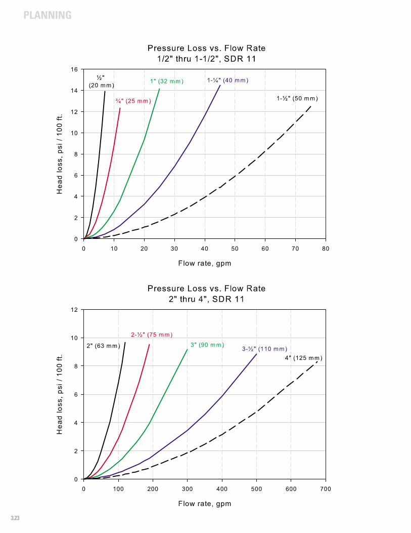
PLANNING
3.23
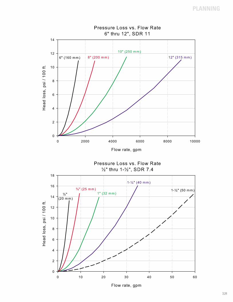
PLANNING
3.24
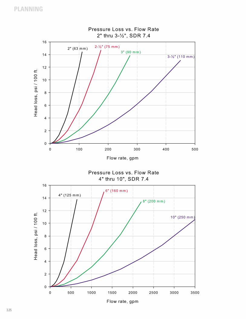
PLANNING
3.25
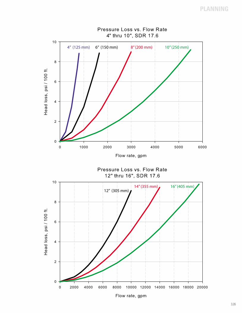
PLANNING
3.26
6” (150 mm)4” (125 mm) 8” (200 mm) 10” (250 mm)
12” (305 mm)14” (355 mm) 16” (405 mm)
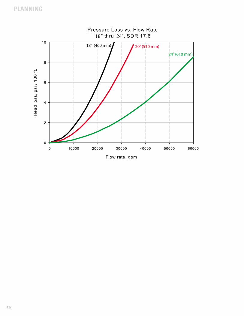
PLANNING
3.27
18 24
18” (460 mm) 20” (510 mm)
24” (610 mm)
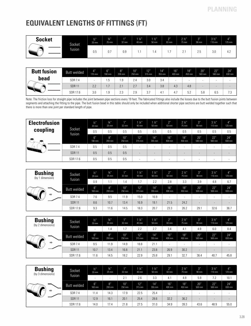
PLANNING
3.28
SocketSocketfusion
½”20 mm
¾”25 mm
1”32 mm
1 ¼”40 mm
1 ½”50 mm
2”63 mm
2 ½”75 mm
3”90 mm
3 ½”110 mm
4”125 mm
0.5 0.7 0.9 1.1 1.4 1.7 2.1 2.5 3.0 4.2
EQUIVALENT LENGTHS OF FITTINGS (FT)
Butt fusion bead
Butt welded 4”125 mm
6”160 mm
8”200 mm
10”250 mm
12”315 mm
14” 355 mm
16”400 mm
18”450 mm
20”500 mm
22”560 mm
24”630 mm
SDR 7.4 - 1.5 1.9 2.4 3.0 3.4 - - - - -
SDR 11 2.2 1.7 2.1 2.7 3.4 3.8 4.3 4.8 - - -
SDR 17.6 3.0 1.9 2.3 2.9 3.7 4.1 4.7 5.2 5.8 6.5 7.3
Electrofusion coupling Socket
fusion
½”20 mm
¾”25 mm
1”32 mm
1 ¼”40 mm
1 ½”50 mm
2”63 mm
2 ½”75 mm
3”90 mm
3 ½”110 mm
4”125 mm
0.5 0.5 0.5 0.5 0.5 0.5 0.5 0.5 0.5 0.5
6”160 mm
8”200 mm
10”250 mm
12”315 mm
14” 355 mm
16”400 mm
18”450 mm
20”500 mm
22”560 mm
24”630 mm
SDR 7.4 0.5 0.5 0.5 - - - - - - -
SDR 11 0.5 0.5 0.5 - - - - - - -
SDR 17.6 0.5 0.5 0.5 - - - - - - -
Bushing(by 1 dimension)
Socketfusion
½”20 mm
¾”25 mm
1”32 mm
1 ¼”40 mm
1 ½”50 mm
2”63 mm
2 ½”75 mm
3”90 mm
3 ½”110 mm
4”125 mm
0.9 1.1 1.4 1.7 2.2 2.8 3.3 3.9 4.8 6.7
Butt welded 6”160 mm
8”200 mm
10”250 mm
12”315 mm
14” 355 mm
16”400 mm
18”450 mm
20”500 mm
22”560 mm
24”630 mm
SDR 7.4 7.6 9.5 11.9 15.0 16.9 - - - - -
SDR 11 8.6 10.7 13.4 16.9 19.1 21.5 24.2 - - -
SDR 17.6 9.3 11.6 14.5 18.3 20.7 23.3 26.2 29.1 32.6 36.7
Bushing(by 2 dimensions)
Socketfusion
½”20 mm
¾”25 mm
1”32 mm
1 ¼”40 mm
1 ½”50 mm
2”63 mm
2 ½”75 mm
3”90 mm
3 ½”110 mm
4”125 mm
- 1.4 1.7 2.2 2.7 3.4 4.1 4.9 6.0 8.4
Butt welded 6”160 mm
8”200 mm
10”250 mm
12”315 mm
14” 355 mm
16”400 mm
18”450 mm
20”500 mm
22”560 mm
24”630 mm
SDR 7.4 9.5 11.9 14.9 18.8 21.1 - - - - -
SDR 11 10.7 13.4 16.8 21.1 23.8 26.9 30.2 - - -
SDR 17.6 11.6 14.5 18.2 22.9 25.8 29.1 32.7 36.4 40.7 45.8
Bushing(by 3 dimensions)
Socketfusion
½”20 mm
¾”25 mm
1”32 mm
1 ¼”40 mm
1 ½”50 mm
2”63 mm
2 ½”75 mm
3”90 mm
3 ½”110 mm
4”125 mm
- - 2.1 2.6 3.3 4.1 4.9 5.9 7.2 10.1
Butt welded 6”160 mm
8”200 mm
10”250 mm
12”315 mm
14” 355 mm
16”400 mm
18”450 mm
20”500 mm
22”560 mm
24”630 mm
SDR 7.4 11.4 14.3 17.9 22.5 25.4 - - - - -
SDR 11 12.9 16.1 20.1 25.4 28.6 32.2 36.2 - - -
SDR 17.6 14.0 17.4 21.8 27.5 31.0 34.9 39.3 43.6 48.9 55.0
Note: The friction loss for straight pipe includes the joint between pipe sections every 19 feet. The fabricated fittings also include the losses due to the butt fusion joints between segments and attaching the fitting to the pipe. The butt fusion bead in this table should only be included when additional shorter pipe sections are butt welded together such that there is more than one joint per standard length of pipe.
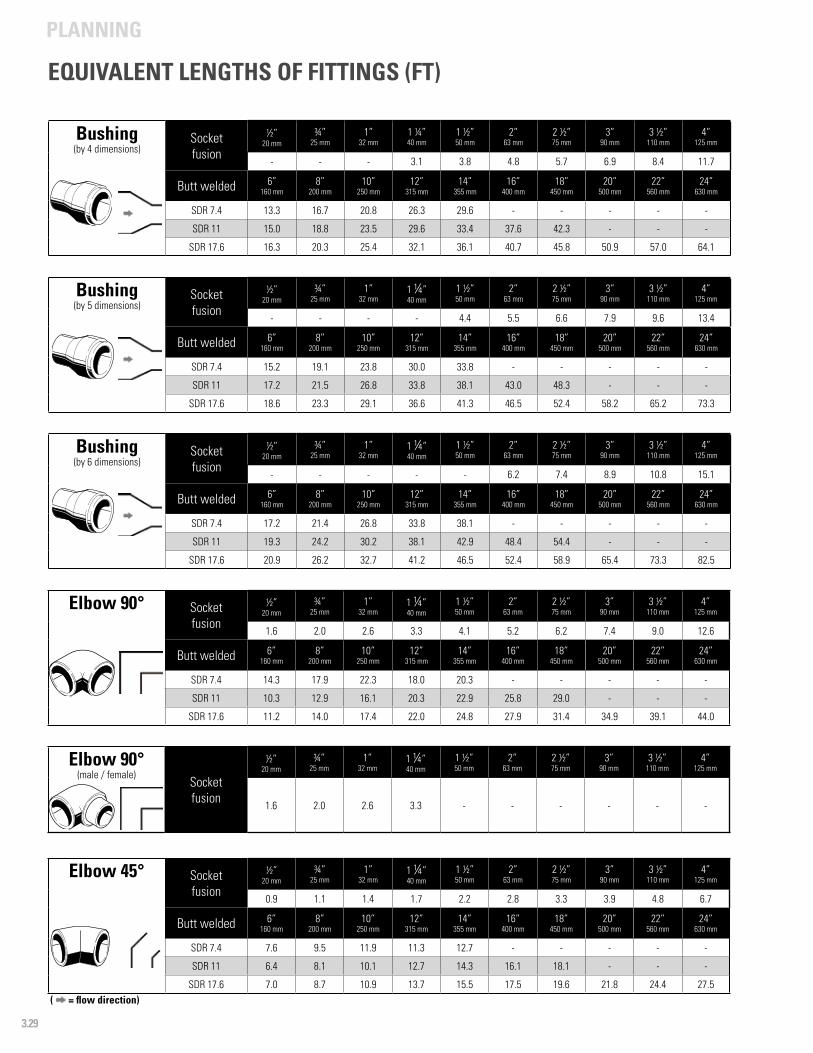
PLANNING
3.29
( = flow direction)
EQUIVALENT LENGTHS OF FITTINGS (FT)
Bushing(by 4 dimensions)
Socketfusion
½”20 mm
¾”25 mm
1”32 mm
1 ¼”40 mm
1 ½”50 mm
2”63 mm
2 ½”75 mm
3”90 mm
3 ½”110 mm
4”125 mm
- - - 3.1 3.8 4.8 5.7 6.9 8.4 11.7
Butt welded 6”160 mm
8”200 mm
10”250 mm
12”315 mm
14” 355 mm
16”400 mm
18”450 mm
20”500 mm
22”560 mm
24”630 mm
SDR 7.4 13.3 16.7 20.8 26.3 29.6 - - - - -
SDR 11 15.0 18.8 23.5 29.6 33.4 37.6 42.3 - - -
SDR 17.6 16.3 20.3 25.4 32.1 36.1 40.7 45.8 50.9 57.0 64.1
Bushing(by 5 dimensions)
Socketfusion
½”20 mm
¾”25 mm
1”32 mm
1 ¼”40 mm
1 ½”50 mm
2”63 mm
2 ½”75 mm
3”90 mm
3 ½”110 mm
4”125 mm
- - - - 4.4 5.5 6.6 7.9 9.6 13.4
Butt welded 6”160 mm
8”200 mm
10”250 mm
12”315 mm
14” 355 mm
16”400 mm
18”450 mm
20”500 mm
22”560 mm
24”630 mm
SDR 7.4 15.2 19.1 23.8 30.0 33.8 - - - - -
SDR 11 17.2 21.5 26.8 33.8 38.1 43.0 48.3 - - -
SDR 17.6 18.6 23.3 29.1 36.6 41.3 46.5 52.4 58.2 65.2 73.3
Bushing(by 6 dimensions)
Socketfusion
½”20 mm
¾”25 mm
1”32 mm
1 ¼”40 mm
1 ½”50 mm
2”63 mm
2 ½”75 mm
3”90 mm
3 ½”110 mm
4”125 mm
- - - - - 6.2 7.4 8.9 10.8 15.1
Butt welded 6”160 mm
8”200 mm
10”250 mm
12”315 mm
14” 355 mm
16”400 mm
18”450 mm
20”500 mm
22”560 mm
24”630 mm
SDR 7.4 17.2 21.4 26.8 33.8 38.1 - - - - -
SDR 11 19.3 24.2 30.2 38.1 42.9 48.4 54.4 - - -
SDR 17.6 20.9 26.2 32.7 41.2 46.5 52.4 58.9 65.4 73.3 82.5
Elbow 90° Socketfusion
½”20 mm
¾”25 mm
1”32 mm
1 ¼”40 mm
1 ½”50 mm
2”63 mm
2 ½”75 mm
3”90 mm
3 ½”110 mm
4”125 mm
1.6 2.0 2.6 3.3 4.1 5.2 6.2 7.4 9.0 12.6
Butt welded 6”160 mm
8”200 mm
10”250 mm
12”315 mm
14” 355 mm
16”400 mm
18”450 mm
20”500 mm
22”560 mm
24”630 mm
SDR 7.4 14.3 17.9 22.3 18.0 20.3 - - - - -
SDR 11 10.3 12.9 16.1 20.3 22.9 25.8 29.0 - - -
SDR 17.6 11.2 14.0 17.4 22.0 24.8 27.9 31.4 34.9 39.1 44.0
Elbow 90°(male / female)
Socketfusion
½”20 mm
¾”25 mm
1”32 mm
1 ¼”40 mm
1 ½”50 mm
2”63 mm
2 ½”75 mm
3”90 mm
3 ½”110 mm
4”125 mm
1.6 2.0 2.6 3.3 - - - - - -
Elbow 45° Socketfusion
½”20 mm
¾”25 mm
1”32 mm
1 ¼”40 mm
1 ½”50 mm
2”63 mm
2 ½”75 mm
3”90 mm
3 ½”110 mm
4”125 mm
0.9 1.1 1.4 1.7 2.2 2.8 3.3 3.9 4.8 6.7
Butt welded 6”160 mm
8”200 mm
10”250 mm
12”315 mm
14” 355 mm
16”400 mm
18”450 mm
20”500 mm
22”560 mm
24”630 mm
SDR 7.4 7.6 9.5 11.9 11.3 12.7 - - - - -
SDR 11 6.4 8.1 10.1 12.7 14.3 16.1 18.1 - - -
SDR 17.6 7.0 8.7 10.9 13.7 15.5 17.5 19.6 21.8 24.4 27.5
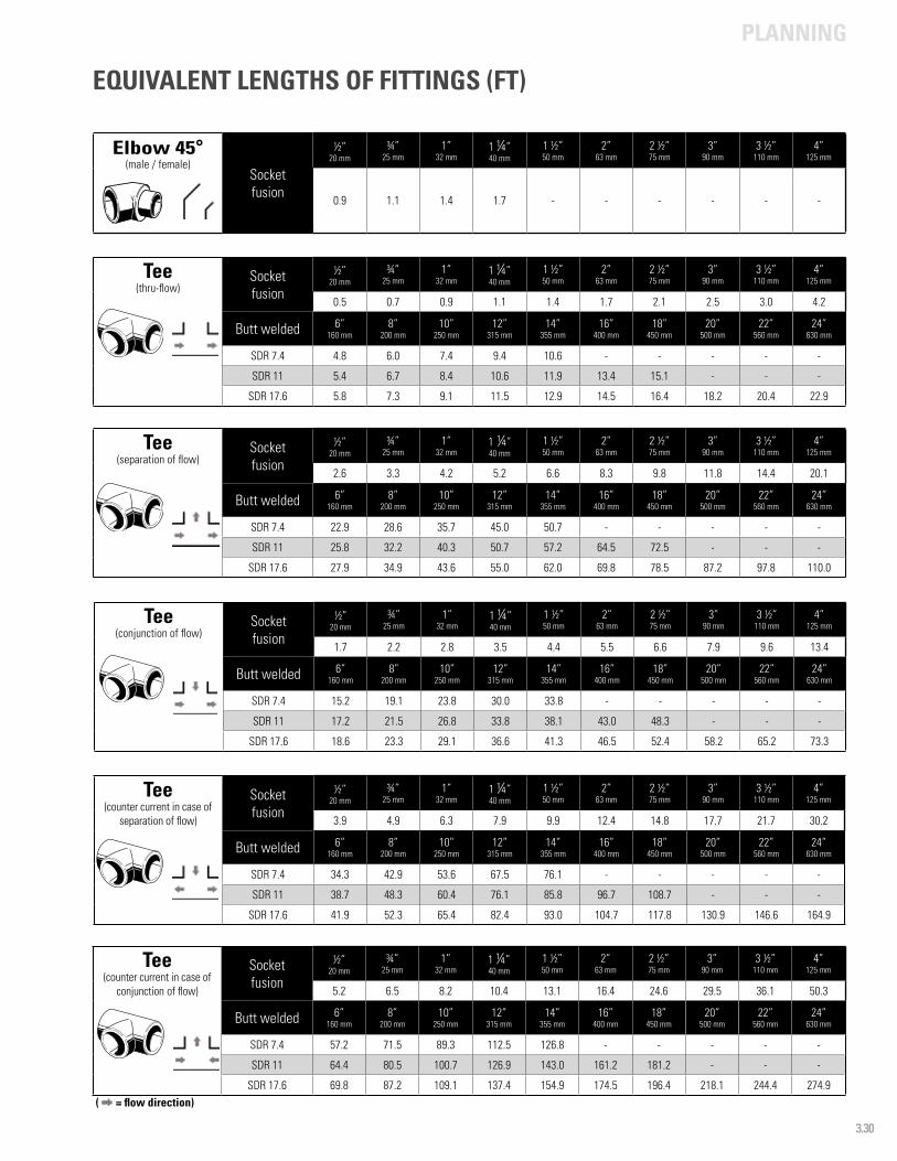
PLANNING
3.30
( = flow direction)
Elbow 45°(male / female)
Socketfusion
½”20 mm
¾”25 mm
1”32 mm
1 ¼”40 mm
1 ½”50 mm
2”63 mm
2 ½”75 mm
3”90 mm
3 ½”110 mm
4”125 mm
0.9 1.1 1.4 1.7 - - - - - -
Tee(thru-flow)
Socketfusion
½”20 mm
¾”25 mm
1”32 mm
1 ¼”40 mm
1 ½”50 mm
2”63 mm
2 ½”75 mm
3”90 mm
3 ½”110 mm
4”125 mm
0.5 0.7 0.9 1.1 1.4 1.7 2.1 2.5 3.0 4.2
Butt welded 6”160 mm
8”200 mm
10”250 mm
12”315 mm
14” 355 mm
16”400 mm
18”450 mm
20”500 mm
22”560 mm
24”630 mm
SDR 7.4 4.8 6.0 7.4 9.4 10.6 - - - - -
SDR 11 5.4 6.7 8.4 10.6 11.9 13.4 15.1 - - -
SDR 17.6 5.8 7.3 9.1 11.5 12.9 14.5 16.4 18.2 20.4 22.9
Tee(separation of flow)
Socketfusion
½”20 mm
¾”25 mm
1”32 mm
1 ¼”40 mm
1 ½”50 mm
2”63 mm
2 ½”75 mm
3”90 mm
3 ½”110 mm
4”125 mm
2.6 3.3 4.2 5.2 6.6 8.3 9.8 11.8 14.4 20.1
Butt welded 6”160 mm
8”200 mm
10”250 mm
12”315 mm
14” 355 mm
16”400 mm
18”450 mm
20”500 mm
22”560 mm
24”630 mm
SDR 7.4 22.9 28.6 35.7 45.0 50.7 - - - - -
SDR 11 25.8 32.2 40.3 50.7 57.2 64.5 72.5 - - -
SDR 17.6 27.9 34.9 43.6 55.0 62.0 69.8 78.5 87.2 97.8 110.0
Tee(conjunction of flow)
Socketfusion
½”20 mm
¾”25 mm
1”32 mm
1 ¼”40 mm
1 ½”50 mm
2”63 mm
2 ½”75 mm
3”90 mm
3 ½”110 mm
4”125 mm
1.7 2.2 2.8 3.5 4.4 5.5 6.6 7.9 9.6 13.4
Butt welded 6”160 mm
8”200 mm
10”250 mm
12”315 mm
14” 355 mm
16”400 mm
18”450 mm
20”500 mm
22”560 mm
24”630 mm
SDR 7.4 15.2 19.1 23.8 30.0 33.8 - - - - -
SDR 11 17.2 21.5 26.8 33.8 38.1 43.0 48.3 - - -
SDR 17.6 18.6 23.3 29.1 36.6 41.3 46.5 52.4 58.2 65.2 73.3
Tee(counter current in case of
separation of flow)
Socketfusion
½”20 mm
¾”25 mm
1”32 mm
1 ¼”40 mm
1 ½”50 mm
2”63 mm
2 ½”75 mm
3”90 mm
3 ½”110 mm
4”125 mm
3.9 4.9 6.3 7.9 9.9 12.4 14.8 17.7 21.7 30.2
Butt welded 6”160 mm
8”200 mm
10”250 mm
12”315 mm
14” 355 mm
16”400 mm
18”450 mm
20”500 mm
22”560 mm
24”630 mm
SDR 7.4 34.3 42.9 53.6 67.5 76.1 - - - - -
SDR 11 38.7 48.3 60.4 76.1 85.8 96.7 108.7 - - -
SDR 17.6 41.9 52.3 65.4 82.4 93.0 104.7 117.8 130.9 146.6 164.9
Tee(counter current in case of
conjunction of flow)
Socketfusion
½”20 mm
¾”25 mm
1”32 mm
1 ¼”40 mm
1 ½”50 mm
2”63 mm
2 ½”75 mm
3”90 mm
3 ½”110 mm
4”125 mm
5.2 6.5 8.2 10.4 13.1 16.4 24.6 29.5 36.1 50.3
Butt welded 6”160 mm
8”200 mm
10”250 mm
12”315 mm
14” 355 mm
16”400 mm
18”450 mm
20”500 mm
22”560 mm
24”630 mm
SDR 7.4 57.2 71.5 89.3 112.5 126.8 - - - - -
SDR 11 64.4 80.5 100.7 126.9 143.0 161.2 181.2 - - -
SDR 17.6 69.8 87.2 109.1 137.4 154.9 174.5 196.4 218.1 244.4 274.9
EQUIVALENT LENGTHS OF FITTINGS (FT)
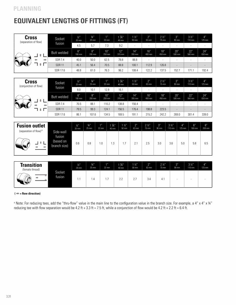
PLANNING
3.31
( = flow direction)
Cross(separation of flow)
Socketfusion
½”20 mm
¾”25 mm
1”32 mm
1 ¼”40 mm
1 ½”50 mm
2”63 mm
2 ½”75 mm
3”90 mm
3 ½”110 mm
4”125 mm
4.5 5.7 7.3 9.2 - - - - - -
Butt welded 6”160 mm
8”200 mm
10”250 mm
12”315 mm
14” 355 mm
16”400 mm
18”450 mm
20”500 mm
22”560 mm
24”630 mm
SDR 7.4 40.0 50.0 62.5 78.8 88.8 - - - - -
SDR 11 45.1 56.4 70.5 88.8 100.1 112.9 126.8 - - -
SDR 17.6 48.8 61.0 76.3 96.2 108.4 122.2 137.5 152.7 171.1 192.4
Cross(conjunction of flow)
Socketfusion
½”20 mm
¾”25 mm
1”32 mm
1 ¼”40 mm
1 ½”50 mm
2”63 mm
2 ½”75 mm
3”90 mm
3 ½”110 mm
4”125 mm
8.0 10.1 12.9 16.1 - - - - - -
Butt welded 6”160 mm
8”200 mm
10”250 mm
12”315 mm
14” 355 mm
16”400 mm
18”450 mm
20”500 mm
22”560 mm
24”630 mm
SDR 7.4 70.5 88.1 110.2 138.8 156.4 - - - - -
SDR 11 79.5 99.3 124.1 156.5 176.4 198.8 223.5 - - -
SDR 17.6 86.1 107.6 134.5 169.5 191.1 215.2 242.2 269.0 301.4 339.0
Fusion outlet(separation of flow) a Side-wall
fusion(based on
branch size)
½”20 mm
¾”25 mm
1”32 mm
1 ¼”40 mm
1 ½”50 mm
2”63 mm
2 ½”75 mm
3”90 mm
3 ½”110 mm
4”125 mm
6”160 mm
8”200 mm
0.6 0.8 1.0 1.3 1.7 2.1 2.5 3.0 3.6 5.0 5.8 6.5
Transition(female thread)
Socketfusion
½”20 mm
¾”25 mm
1”32 mm
1 ¼”40 mm
1 ½”50 mm
2”63 mm
2 ½”75 mm
3”90 mm
3 ½”110 mm
4”125 mm
1.1 1.4 1.7 2.2 2.7 3.4 4.1 - - -
a Note: For reducing tees, add the “thru-flow” value in the main line to the configuration value in the branch size. For example, a 4” x 4” x ¾” reducing tee with flow separation would be 4.2 ft + 3.3 ft = 7.5 ft, while a conjunction of flow would be 4.2 ft + 2.2 ft = 6.4 ft.
EQUIVALENT LENGTHS OF FITTINGS (FT)
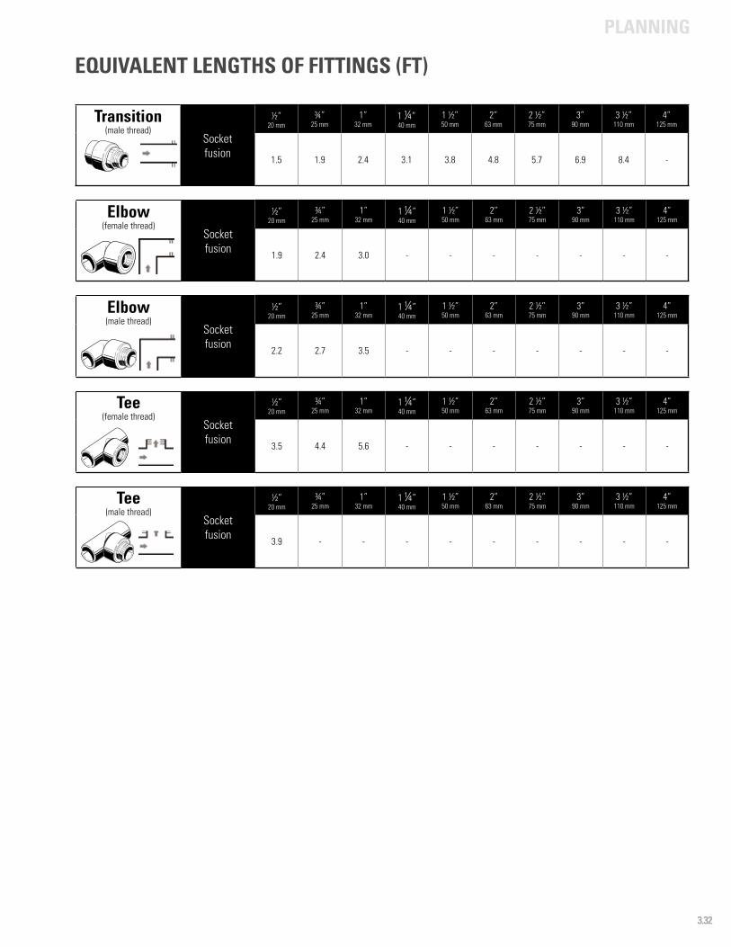
PLANNING
3.32
Transition(male thread)
Socketfusion
½”20 mm
¾”25 mm
1”32 mm
1 ¼”40 mm
1 ½”50 mm
2”63 mm
2 ½”75 mm
3”90 mm
3 ½”110 mm
4”125 mm
1.5 1.9 2.4 3.1 3.8 4.8 5.7 6.9 8.4 -
Elbow(female thread)
Socketfusion
½”20 mm
¾”25 mm
1”32 mm
1 ¼”40 mm
1 ½”50 mm
2”63 mm
2 ½”75 mm
3”90 mm
3 ½”110 mm
4”125 mm
1.9 2.4 3.0 - - - - - - -
Elbow(male thread)
Socketfusion
½”20 mm
¾”25 mm
1”32 mm
1 ¼”40 mm
1 ½”50 mm
2”63 mm
2 ½”75 mm
3”90 mm
3 ½”110 mm
4”125 mm
2.2 2.7 3.5 - - - - - - -
Tee(female thread)
Socketfusion
½”20 mm
¾”25 mm
1”32 mm
1 ¼”40 mm
1 ½”50 mm
2”63 mm
2 ½”75 mm
3”90 mm
3 ½”110 mm
4”125 mm
3.5 4.4 5.6 - - - - - - -
Tee(male thread)
Socketfusion
½”20 mm
¾”25 mm
1”32 mm
1 ¼”40 mm
1 ½”50 mm
2”63 mm
2 ½”75 mm
3”90 mm
3 ½”110 mm
4”125 mm
3.9 - - - - - - - - -
EQUIVALENT LENGTHS OF FITTINGS (FT)
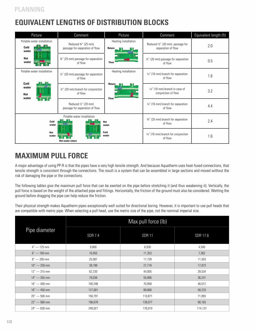
PLANNING
3.33
Picture Comment Picture Comment Equivalent length (ft)Potable water installation
Reduced ¾” (25 mm)passage for separation of flow
Heating installationReduced ½” (20 mm) passage for
separation of flow 2.0
¾” (25 mm) passage for separation of flow
½” (20 mm) passage for separation of flow 0.5
Potable water installation½” (20 mm) passage for separation
of flow
Heating installation3/8” (16 mm) branch for separation
of flow 1.6
½” (20 mm) branch for conjunction of flow
3/8” (16 mm) branch in case of conjunction of flow 3.2
Reduced ½” (20 mm) passage for separation of flow
3/8” (16 mm) branch for separation of flow 4.4
Potable water installation¾” (25 mm) branch for separation
of flow 2.4
3/8” (16 mm) branch for conjunction of flow 1.6
Coldwater
Hotwater
Coldwater
Hotwater
Return
Flow
Flow
Return
Coldwater
Coldwater
Hotwater
Hotwater
Hot water return
Pipe diameterMax pull force (lb)
SDR 7.4 SDR 11 SDR 17.6
4“ — 125 mm 9,800 6,930 4,500
6” — 160 mm 16,055 11,353 7,362
8” — 200 mm 25,087 17,739 11,503
10” — 250 mm 39,198 27,718 17,973
12” — 315 mm 62,230 44,005 28,534
14” — 355 mm 79,038 55,890 36,241
16” — 400 mm 100,346 70,958 46,012
18” — 450 mm 127,001 89,806 58,233
20” — 500 mm 156,791 110,871 71,893
22” — 560 mm 196,678 139,077 90,183
24” — 630 mm 248,921 176,019 114,137
MAXIMUM PULL FORCEA major advantage of using PP-R is that the pipes have a very high tensile strength. And because Aquatherm uses heat-fused connections, that tensile strength is consistent through the connections. The result is a system that can be assembled in large sections and moved without the risk of damaging the pipe or the connections.
The following tables give the maximum pull force that can be exerted on the pipe before stretching it (and thus weakening it). Vertically, the pull force is based on the weight of the attached pipe and fittings. Horizontally, the friction of the ground must also be considered. Wetting the ground before dragging the pipe can help reduce the friction.
Their physical strength makes Aquatherm pipes exceptionally well suited for directional boring. However, it is important to use pull heads that are compatible with metric pipe. When selecting a pull head, use the metric size of the pipe, not the nominal imperial size.
EQUIVALENT LENGTHS OF DISTRIBUTION BLOCKS
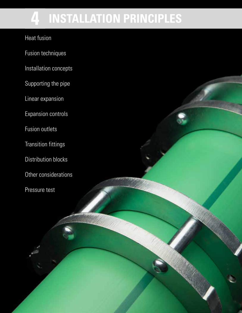
Heat fusion
Fusion techniques
Installation concepts
Supporting the pipe
Linear expansion
Expansion controls
Fusion outlets
Transition fittings
Distribution blocks
Other considerations
Pressure test
INSTALLATION PRINCIPLES4

4.1
INSTALLATION PRINCIPLES
All Aquatherm piping products are made from the same reliable PP-R material and are engineered to be heat fused together.
Since pipes and fittings come in sizes ranging from ½” to 24” in diameter, the fusion process, equipment required, and installation time will vary, but the principles of heat fusion remain the same.
For a proper heat fusion connection, the two surfaces being fused are heated to a melting temperature, pressed together, and allowed to cool under pressure. This process allows the PP-R chains to reform as one, joining the pieces together without the need for glues, solders, gaskets, or other foreign materials.
By eliminating the foreign materials in the connection, heat fusion removes the most likely source of leaks and failures. The fused portion of the pipe also retains its flexibility and resistance to impact, making the connection easier and safer to prefabricate and transport. In short, a properly fused joint behaves as if it were manufactured that way.
There are several methods of fusion used in joining Aquatherm pipes. Each of these methods, if properly executed, will provide a connection that is stronger than the pipe itself.
A final pressure test will help verify the integrity of the connections, and drastically reduce the risk of failure due to improper installation. Aquatherm’s heat fusion training courses are designed to help installers know when to employ each of these different methods and to become skilled in using them.
HEAT FUSION CONNECTIONS
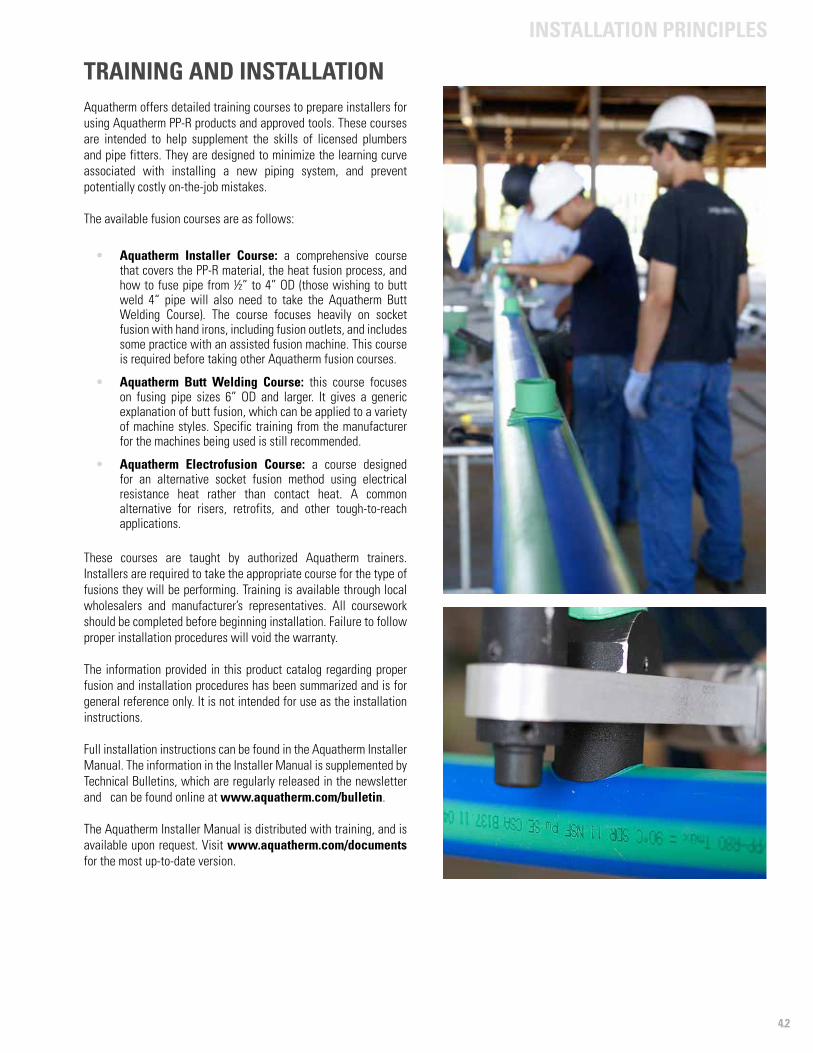
4.2
INSTALLATION PRINCIPLES
TRAINING AND INSTALLATIONAquatherm offers detailed training courses to prepare installers for using Aquatherm PP-R products and approved tools. These courses are intended to help supplement the skills of licensed plumbers and pipe fitters. They are designed to minimize the learning curve associated with installing a new piping system, and prevent potentially costly on-the-job mistakes.
The available fusion courses are as follows:
• Aquatherm Installer Course: a comprehensive course that covers the PP-R material, the heat fusion process, and how to fuse pipe from ½” to 4” OD (those wishing to butt weld 4“ pipe will also need to take the Aquatherm Butt Welding Course). The course focuses heavily on socket fusion with hand irons, including fusion outlets, and includes some practice with an assisted fusion machine. This course is required before taking other Aquatherm fusion courses.
• Aquatherm Butt Welding Course: this course focuses on fusing pipe sizes 6” OD and larger. It gives a generic explanation of butt fusion, which can be applied to a variety of machine styles. Specific training from the manufacturer for the machines being used is still recommended.
• Aquatherm Electrofusion Course: a course designed for an alternative socket fusion method using electrical resistance heat rather than contact heat. A common alternative for risers, retrofits, and other tough-to-reach applications.
These courses are taught by authorized Aquatherm trainers. Installers are required to take the appropriate course for the type of fusions they will be performing. Training is available through local wholesalers and manufacturer’s representatives. All coursework should be completed before beginning installation. Failure to follow proper installation procedures will void the warranty.
The information provided in this product catalog regarding proper fusion and installation procedures has been summarized and is for general reference only. It is not intended for use as the installation instructions.
Full installation instructions can be found in the Aquatherm Installer Manual. The information in the Installer Manual is supplemented by Technical Bulletins, which are regularly released in the newsletter and can be found online at www.aquatherm.com/bulletin.
The Aquatherm Installer Manual is distributed with training, and is available upon request. Visit www.aquatherm.com/documents for the most up-to-date version.
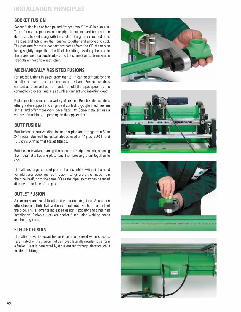
4.3
INSTALLATION PRINCIPLES
SOCKET FUSIONSocket fusion is used for pipe and fittings from ½” to 4” in diameter. To perform a proper fusion, the pipe is cut, marked for insertion depth, and heated along with the socket fitting for a specified time. The pipe and fitting are then pushed together and allowed to cool. The pressure for these connections comes from the OD of the pipe being slightly larger than the ID of the fitting. Marking the pipe to the proper welding depth helps bring the connection to its maximum strength without flow restriction.
MECHANICALLY ASSISTED FUSIONSFor socket fusions in sizes larger than 2”, it can be difficult for one installer to make a proper connection by hand. Fusion machines can act as a second pair of hands to hold the pipe, speed up the connection process, and assist with alignment and insertion depth.
Fusion machines come in a variety of designs. Bench-style machines offer greater support and alignment control. Jig-style machines are lighter and offer more workspace flexibility. Some installers use a variety of machines, depending on the application.
BUTT FUSIONButt fusion (or butt welding) is used for pipe and fittings from 6” to 24” in diameter. Butt fusion can also be used on 4” pipe (SDR 11 and 17.6 only) with normal socket fittings.
Butt fusion involves planing the ends of the pipe smooth, pressing them against a heating plate, and then pressing them together to cool.
This allows larger sizes of pipe to be assembled without the need for additional couplings. Butt fusion fittings are either made from the pipe itself, or to the same OD as the pipe, so they can be fused directly to the face of the pipe.
OUTLET FUSIONAs an easy and reliable alternative to reducing tees, Aquatherm offers fusion outlets that can be installed directly onto the outside of the pipe. This allows for increased design flexibility and simplified installation. Fusion outlets are socket fused using welding heads and heating irons.
ELECTROFUSIONThis alternative to socket fusion is commonly used when space is very limited, or the pipe cannot be moved laterally in order to perform a fusion. Heat is generated by a current run through electrical coils inside the fittings.
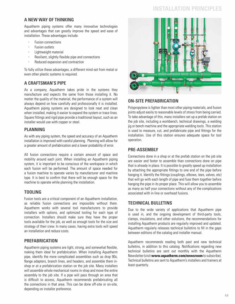
4.4
INSTALLATION PRINCIPLES
A NEW WAY OF THINKINGAquatherm piping systems offer many innovative technologies and advantages that can greatly improve the speed and ease of installation. These advantages include:
• Fusion connections• Fusion outlets• Lightweight material• Resilient, slightly flexible pipe and connections• Reduced expansion and contraction
To fully utilize these advantages, a different mind-set from metal or even other plastic systems is required.
A CRAFTSMAN’S PIPEAs a company, Aquatherm takes pride in the systems they manufacture and expects the same from those installing it. No matter the quality of the material, the performance of a system will always depend on how carefully and professionally it is installed. Aquatherm piping systems are designed to look neat and clean when installed, making it easier to expand the system or trace lines. Square fittings and rigid pipe provide a traditional layout, such as an installer would use with copper or steel.
PLANNING As with any piping system, the speed and accuracy of an Aquatherm installation is improved with careful planning. Planning will allow for a greater amount of prefabrication and a lower probability of error.
All fusion connections require a certain amount of space and mobility around each joint. When installing an Aquatherm piping system, it is important to be conscious of the workspace in which each fusion will be performed. The amount of space needed for a fusion machine to operate varies by manufacturer and machine type. It is best to confirm that there will be enough space for the machine to operate while planning the installation.
TOOLING Fusion tools are a critical component of an Aquatherm installation, as reliable fusion connections are impossible without them. Aquatherm works with several tool manufacturers to provide installers with options, and optimized tooling for each type of connection. Installers should make sure they have the proper tools available for the job, as well as enough tools for the size and strategy of their crew. In many cases, having extra tools will speed an installation and reduce costs.
PREFABRICATIONAquatherm piping systems are light, strong, and somewhat flexible, making them ideal for prefabrication. When installing Aquatherm pipe, identify the more complicated assemblies such as drop 90s, flange adapters, branch lines, and headers, and assemble them in-shop or at a prefabrication station on the job site. Many installers will assemble whole mechanical rooms in-shop and move the entire assembly to the job site. If a pipe will pass through an area that is difficult to access, Aquatherm recommends prefabricating all the connections in that area. This can be done off-site or on-site, depending on installer preference.
ON-SITE PREFABRICATIONPolypropylene is lighter than most other piping materials, and fusion joints adjust easily to reasonable levels of stress from being carried. To take advantage of this, many installers set up a prefab station on the job site, including a workbench, technical drawings, a welding jig or bench machine and the appropriate welding tools. This station is used to measure, cut, and prefabricate pipe and fittings for the installation. Use of this station ensures adequate space for tool operation.
PRE-ASSEMBLY Connections done in a shop or at the prefab station on the job site are easier and faster to assemble than connections done on pipe that is already in place. It is possible to greatly speed up installation by attaching the appropriate fittings to one end of the pipe before hanging it. Identify the fittings (couplings, elbows, tees, valves, etc) that will go with each length of pipe and fuse them together before hanging the pipe in its proper place. This will allow you to assemble as many as half your connections without any of the complications associated with in-line or overhead fusions.
TECHNICAL BULLETINSDue to the wide variety of applications that Aquatherm pipe is used in, and the ongoing development of third-party tools, clamps, insulations, and other solutions, the recommendations for installing Aquatherm products are regularly improved and updated. Aquatherm regularly releases technical bulletins to fill in the gaps between editions of the catalog and installer manual.
Aquatherm recommends reading both past and new technical bulletins, in addition to this catalog. Notifications regarding new technical bulletins are sent out monthly with the Aquatherm Newsletter (visit www.aquatherm.com/newsroom to subscribe). Technical bulletins are sent to Aquatherm’s installers and trainers at least quarterly.
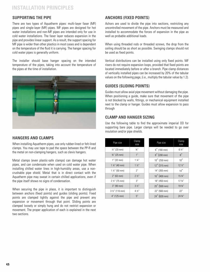
4.5
INSTALLATION PRINCIPLES
SUPPORTING THE PIPEThere are two types of Aquatherm pipes: multi-layer faser (MF) pipes and single-layer (MF) pipes. MF pipes are designed for hot water installations and non-MF pipes are intended only for use in cold water installations. The faser layer reduces expansion in the pipe and provides linear support. As a result, the support spacing for MF pipe is wider than other plastics in most cases and is dependent on the temperature of the fluid it is carrying. The hanger spacing for cold water pipes is generally uniform.
The installer should base hanger spacing on the intended temperature of the pipes, taking into account the temperature of the pipes at the time of installation.
HANGERS AND CLAMPSWhen installing Aquatherm pipes, use only rubber-lined or felt-lined clamps. You may use tape to pad the space between the PP-R and the metal on non-clamping hangers, such as clevis hangers.
Metal clamps (even plastic-safe clamps) can damage hot water pipes, and can condensate when used on cold water pipe. When installing chilled water lines in high-humidity areas, use a non-crushable pipe shield. Metal that is in direct contact with the Aquatherm pipe may sweat in certain chilled applications, even if the pipe itself shows no signs of condensation.
When securing the pipe in place, it is important to distinguish between anchors (fixed points) and guides (sliding points). Fixed points are clamped tightly against the pipe and prevent any expansion or movement through that point. Sliding points are clamped loosely or simply hung and do not restrict expansion or movement. The proper application of each is explained in the next two sections.
ANCHORS (FIXED POINTS)Achors are used to divide the pipe into sections, restricting any uncontrolled movement of the pipe. Anchors must be measured and installed to accommodate the forces of expansion in the pipe as well as probable additional loads.
When using threaded rods or threaded screws, the drop from the ceiling should be as short as possible. Swinging clamps should not be used as fixed points.
Vertical distributions can be installed using only fixed points. MF risers do not require expansion loops, provided that fixed points are located immediately before or after a branch. Pipe clamp distances of vertically installed pipes can be increased by 20% of the tabular values on the following page, (i.e., multiply the tabular value by 1.2).
GUIDES (SLIDING POINTS)Guides must allow axial pipe movement without damaging the pipe. When positioning a guide, make sure that movement of the pipe is not blocked by walls, fittings, or mechanical equipment installed next to the clamp or hanger. Guides must allow expansion to pass through
CLAMP AND HANGER SIZINGUse the following table to find the approximate imperial OD for supporting bare pipe. Larger clamps will be needed to go over insulation and/or pipe shields.
Pipe size Clampsize Pipe size Clamp
size
½” (20 mm) ¾” 6” (160 mm) 6 ½”
¾” (25 mm) 1” 8” (200 mm) 8”1” (32 mm) 1 ¼” 10” (250 mm) 10”
1 ¼” (40 mm) 1 ½” 12” (315 mm) 12 ½”
1 ½” (50 mm) 2” 14” (355 mm) 14”2” (63 mm) 2 ½” 16” (400 mm) 15 ¾”
2 ½” (75 mm) 3” 18” (450 mm) 17 ¾”
3” (90 mm) 3 ½” 20” (500 mm) 19 ¾”
3 ½” (110 mm) 4 ½” 22” (560 mm) 22”
4” (125 mm) 5” 24” (630 mm) 24 ¾”
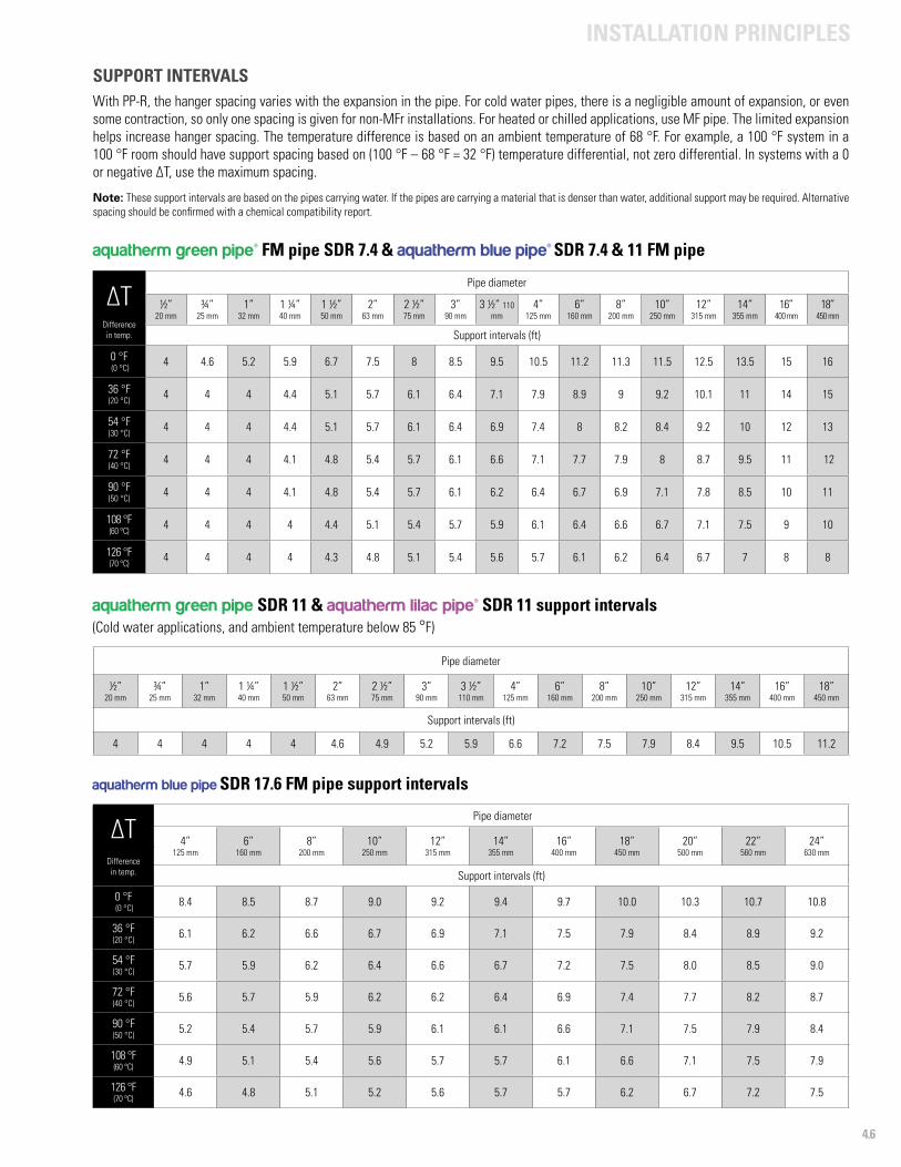
4.6
INSTALLATION PRINCIPLES
aquatherm green pipe SDR 11 & aquatherm lilac pipe® SDR 11 support intervals(Cold water applications, and ambient temperature below 85 °F)
Pipe diameter
½”20 mm
¾”25 mm
1”32 mm
1 ¼”40 mm
1 ½”50 mm
2”63 mm
2 ½”75 mm
3”90 mm
3 ½”110 mm
4”125 mm
6”160 mm
8”200 mm
10”250 mm
12”315 mm
14”355 mm
16”400 mm
18”450 mm
Support intervals (ft)
4 4 4 4 4 4.6 4.9 5.2 5.9 6.6 7.2 7.5 7.9 8.4 9.5 10.5 11.2
SUPPORT INTERVALSWith PP-R, the hanger spacing varies with the expansion in the pipe. For cold water pipes, there is a negligible amount of expansion, or even some contraction, so only one spacing is given for non-MFr installations. For heated or chilled applications, use MF pipe. The limited expansion helps increase hanger spacing. The temperature difference is based on an ambient temperature of 68 °F. For example, a 100 °F system in a 100 °F room should have support spacing based on (100 °F – 68 °F = 32 °F) temperature differential, not zero differential. In systems with a 0 or negative ∆T, use the maximum spacing.
Note: These support intervals are based on the pipes carrying water. If the pipes are carrying a material that is denser than water, additional support may be required. Alternative spacing should be confirmed with a chemical compatibility report.
∆T
Pipe diameter
½” 20 mm
¾” 25 mm
1” 32 mm
1 ¼”40 mm
1 ½” 50 mm
2” 63 mm
2 ½” 75 mm
3” 90 mm
3 ½” 110 mm
4” 125 mm
6” 160 mm
8” 200 mm
10” 250 mm
12” 315 mm
14” 355 mm
16”400 mm
18”450 mm
Difference in temp. Support intervals (ft)
0 °F (0 °C) 4 4.6 5.2 5.9 6.7 7.5 8 8.5 9.5 10.5 11.2 11.3 11.5 12.5 13.5 15 16
36 °F (20 °C) 4 4 4 4.4 5.1 5.7 6.1 6.4 7.1 7.9 8.9 9 9.2 10.1 11 14 15
54 °F (30 °C) 4 4 4 4.4 5.1 5.7 6.1 6.4 6.9 7.4 8 8.2 8.4 9.2 10 12 13
72 °F (40 °C) 4 4 4 4.1 4.8 5.4 5.7 6.1 6.6 7.1 7.7 7.9 8 8.7 9.5 11 12
90 °F (50 °C) 4 4 4 4.1 4.8 5.4 5.7 6.1 6.2 6.4 6.7 6.9 7.1 7.8 8.5 10 11
108 °F (60 °C) 4 4 4 4 4.4 5.1 5.4 5.7 5.9 6.1 6.4 6.6 6.7 7.1 7.5 9 10
126 °F (70 °C) 4 4 4 4 4.3 4.8 5.1 5.4 5.6 5.7 6.1 6.2 6.4 6.7 7 8 8
aquatherm blue pipe SDR 17.6 FM pipe support intervals
∆T
Pipe diameter
4” 125 mm
6” 160 mm
8” 200 mm
10” 250 mm
12” 315 mm
14” 355 mm
16” 400 mm
18” 450 mm
20”500 mm
22”560 mm
24”630 mm
Difference in temp. Support intervals (ft)
0 °F (0 °C) 8.4 8.5 8.7 9.0 9.2 9.4 9.7 10.0 10.3 10.7 10.8
36 °F (20 °C) 6.1 6.2 6.6 6.7 6.9 7.1 7.5 7.9 8.4 8.9 9.2
54 °F (30 °C) 5.7 5.9 6.2 6.4 6.6 6.7 7.2 7.5 8.0 8.5 9.0
72 °F (40 °C) 5.6 5.7 5.9 6.2 6.2 6.4 6.9 7.4 7.7 8.2 8.7
90 °F (50 °C) 5.2 5.4 5.7 5.9 6.1 6.1 6.6 7.1 7.5 7.9 8.4
108 °F (60 °C) 4.9 5.1 5.4 5.6 5.7 5.7 6.1 6.6 7.1 7.5 7.9
126 °F (70 °C) 4.6 4.8 5.1 5.2 5.6 5.7 5.7 6.2 6.7 7.2 7.5
aquatherm green pipe® FM pipe SDR 7.4 & aquatherm blue pipe® SDR 7.4 & 11 FM pipe
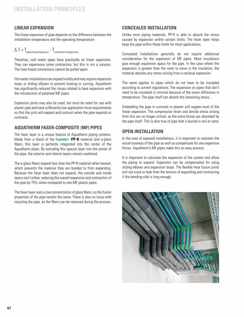
4.7
INSTALLATION PRINCIPLES
LINEAR EXPANSIONThe linear expansion of pipe depends on the difference between the installation temperature and the operating temperature:
∆ T = Toperating temperature - Tinstallation temperature
Therefore, cold water pipes have practically no linear expansion. They can experience some contraction, but this is not a concern. The heat-fused connections cannot be pulled apart.
Hot water installations can expand visibly and may require expansion loops or sliding elbows to prevent bowing or curving. Aquatherm has significantly reduced the issues related to heat expansion with the introduction of patented MF pipes.
Expansion joints may also be used, but must be rated for use with plastic pipe and have sufficiently low application force requirements so that the joint will expand and contract when the pipe expands or contracts.
AQUATHERM FASER-COMPOSITE (MF) PIPESThe faser layer is a unique feature of Aquatherm piping systems. Made from a blend of the fusiolen® PP-R material and e-glass fibers, this layer is perfectly integrated into the center of the Aquatherm pipes. By extruding this special layer into the center of the pipe, the exterior and interior layers remain unaltered.
The e-glass fibers expand less than the PP-R material when heated, which prevents the material they are bonded to from expanding. Because the faser layer does not expand, the outside and inside layers can’t either, reducing the overall expansion and contraction of the pipe by 75% when compared to non-MF plastic pipes.
The faser layer uses a low concentration of glass fibers, so the fusion properties of the pipe remain the same. There is also no issue with recycling the pipe, as the fibers can be removed during the process.
CONCEALED INSTALLATIONUnlike most piping materials, PP-R is able to absorb the stress caused by expansion within certain limits. The faser layer helps keep the pipe within these limits for most applications.
Concealed installations generally do not require additional consideration for the expansion of MF pipes. Most insulations give enough expansion space for the pipe. In the case where the expansion is greater than the room to move in the insulation, the material absorbs any stress arising from a residual expansion.
The same applies to pipes which do not have to be insulated according to current regulations. The expansion on pipes that don’t need to be insulated is minimal because of the lower difference in temperature. The pipe itself can absorb the remaining stress.
Embedding the pipe in concrete or plaster will negate most of the linear expansion. The compressive strain and tensile stress arising from this are no longer critical, as the extra forces are absorbed by the pipe itself. This is also true of pipe that is buried in soil or sand.
OPEN INSTALLATIONIn the case of exposed installations, it is important to maintain the visual trueness of the pipe as well as compensate for any expansive forces. Aquatherm’s MF pipes make this an easy process.
It is important to calculate the expansion of the system and allow the piping to expand. Expansion can be compensated for using sliding elbows and expansion loops. The flexible heat fusion joints will not crack or leak from the tension of expanding and contracting if the bending side is long enough.
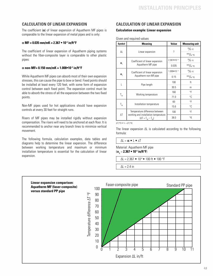
4.8
INSTALLATION PRINCIPLES
CALCULATION OF LINEAR EXPANSIONThe coefficient (α) of linear expansion of Aquatherm MF pipes is comparable to the linear expansion of metal pipes and is only:
α MF = 0.035 mm/mK = 2.367 • 10-4 in/ft°F
The coefficient of linear expansion of Aquatherm piping systems without the fiber-composite layer is comparable to other plastic pipes:
α non-MF= 0.150 mm/mK = 1.008•10-3 in/ft°F
While Aquatherm MF pipes can absorb most of their own expansion stresses, this can cause the pipe to bow or bend. Fixed points should be installed at least every 120 feet, with some form of expansion control between each fixed point. The expansion control must be able to absorb the stress of all the expansion between the two fixed points.
Non-MF pipes used for hot applications should have expansion controls at every 30 feet for straight runs.
Risers of MF pipes may be installed rigidly without expansion compensation. The risers will need to be anchored at each floor. It is recommended to anchor near any branch lines to minimize vertical movement.
The following formula, calculation examples, data tables and diagrams help to determine the linear expansion. The difference between working temperature and maximum or minimum installation temperature is essential for the calculation of linear expansion.
CALCULATION OF LINEAR EXPANSIONCalculation example: Linear expansion
Given and required valuesSymbol Meaning Value Measuring unit
∆L Linear expansion ?in⁄ft °F
mm⁄m °K
α1 Coefficient of linear expansion
Aquatherm MF pipe
2.367•10 -4 in⁄ft °F
0.035 mm⁄m °K
α2
Coefficient of linear expansion Aquatherm non-MF pipe
1.008•10 -3 in⁄ft °F
0.15 mm⁄m °K
L Pipe length100 ft
30.5 m
TW Working temperature160 °F
71.0 °C
TM Installation temperature60 °F
15.6 °C
∆TTemperature difference between
working and installation temperature (∆T = TW – TM)
100 °F
38.0 °K
∆T [°F] • 5⁄9 = ∆T [°K]
The linear expansion ∆L is calculated according to the following formula:
∆L = α • L • ∆T
Material: Aquatherm MF pipe(α1 = 2.367 • 10-4 in/ft°F)
∆L = 2.367 • 10-4 • 100 ft • 100 °F
∆L = 2.4 in
Linear expansion comparison:Aquatherm MF (faser-composite)versus standard PP pipe
0 1 2 3 4 5 6 7 8 9 10 110102030405060708090
100
Tem
pera
ture
diff
eren
ce ∆
T °F
Expansion ∆L in/ft
Faser-composite pipe Standard PP pipe
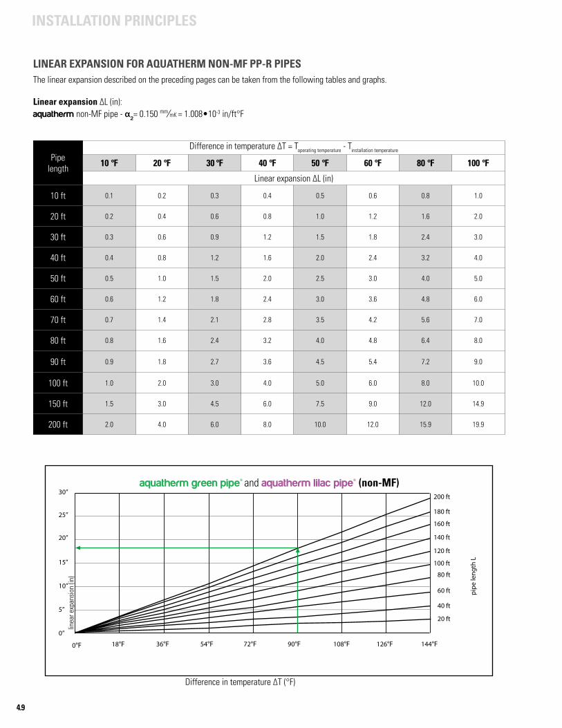
4.9
INSTALLATION PRINCIPLES
LINEAR EXPANSION FOR AQUATHERM NON-MF PP-R PIPESThe linear expansion described on the preceding pages can be taken from the following tables and graphs.
Linear expansion ∆L (in):aquatherm non-MF pipe - α2= 0.150 mm⁄mK = 1.008•10-3 in/ft°F
Pipelength
Difference in temperature ∆T = Toperating temperature - Tinstallation temperature
10 °F 20 °F 30 °F 40 °F 50 °F 60 °F 80 °F 100 °F
Linear expansion ∆L (in)
10 ft 0.1 0.2 0.3 0.4 0.5 0.6 0.8 1.0
20 ft 0.2 0.4 0.6 0.8 1.0 1.2 1.6 2.0
30 ft 0.3 0.6 0.9 1.2 1.5 1.8 2.4 3.0
40 ft 0.4 0.8 1.2 1.6 2.0 2.4 3.2 4.0
50 ft 0.5 1.0 1.5 2.0 2.5 3.0 4.0 5.0
60 ft 0.6 1.2 1.8 2.4 3.0 3.6 4.8 6.0
70 ft 0.7 1.4 2.1 2.8 3.5 4.2 5.6 7.0
80 ft 0.8 1.6 2.4 3.2 4.0 4.8 6.4 8.0
90 ft 0.9 1.8 2.7 3.6 4.5 5.4 7.2 9.0
100 ft 1.0 2.0 3.0 4.0 5.0 6.0 8.0 10.0
150 ft 1.5 3.0 4.5 6.0 7.5 9.0 12.0 14.9
200 ft 2.0 4.0 6.0 8.0 10.0 12.0 15.9 19.9
aquatherm green pipe® and aquatherm lilac pipe® (non-MF)
Difference in temperature ∆T (°F)
30”
25”
20”
15”
10”
5”
0”
18°F 36°F 54°F 72°F 90°F 108°F 126°F 144°F
200 ft
180 ft
160 ft
140 ft
120 ft
100 ft
80 ft
60 ft
40 ft
20 ft
Fusiotherm¨-pipe
Difference in temperature ∆ [ °F]
pipe
leng
th L
0°F
linea
r exp
ansi
on (i
n)
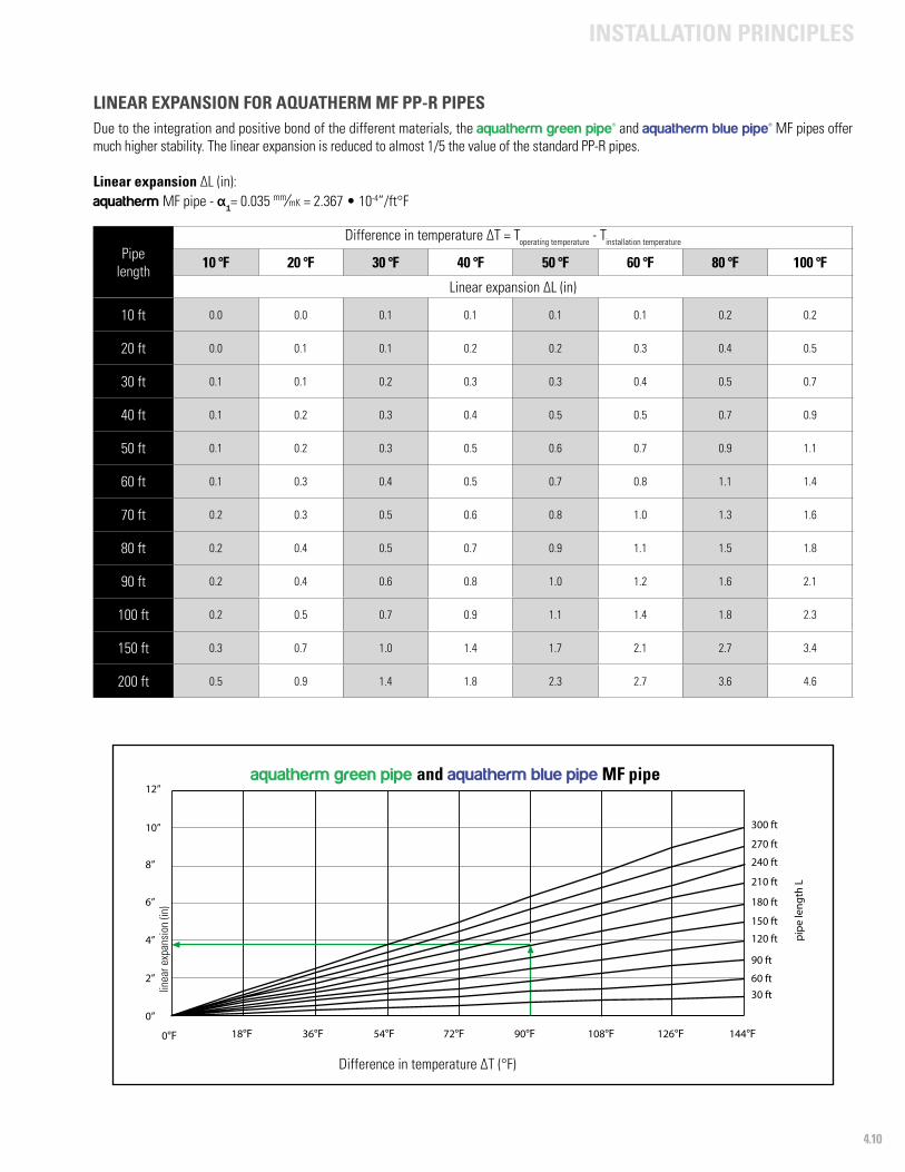
4.10
INSTALLATION PRINCIPLES
LINEAR EXPANSION FOR AQUATHERM MF PP-R PIPESDue to the integration and positive bond of the different materials, the aquatherm green pipe® and aquatherm blue pipe® MF pipes offer much higher stability. The linear expansion is reduced to almost 1/5 the value of the standard PP-R pipes.
Linear expansion ∆L (in):aquatherm MF pipe - α1= 0.035 mm⁄mK = 2.367 • 10-4”/ft°F
Pipelength
Difference in temperature ∆T = Toperating temperature - Tinstallation temperature
10 °F 20 °F 30 °F 40 °F 50 °F 60 °F 80 °F 100 °F
Linear expansion ∆L (in)
10 ft 0.0 0.0 0.1 0.1 0.1 0.1 0.2 0.2
20 ft 0.0 0.1 0.1 0.2 0.2 0.3 0.4 0.5
30 ft 0.1 0.1 0.2 0.3 0.3 0.4 0.5 0.7
40 ft 0.1 0.2 0.3 0.4 0.5 0.5 0.7 0.9
50 ft 0.1 0.2 0.3 0.5 0.6 0.7 0.9 1.1
60 ft 0.1 0.3 0.4 0.5 0.7 0.8 1.1 1.4
70 ft 0.2 0.3 0.5 0.6 0.8 1.0 1.3 1.6
80 ft 0.2 0.4 0.5 0.7 0.9 1.1 1.5 1.8
90 ft 0.2 0.4 0.6 0.8 1.0 1.2 1.6 2.1
100 ft 0.2 0.5 0.7 0.9 1.1 1.4 1.8 2.3
150 ft 0.3 0.7 1.0 1.4 1.7 2.1 2.7 3.4
200 ft 0.5 0.9 1.4 1.8 2.3 2.7 3.6 4.6
aquatherm green pipe and aquatherm blue pipe MF pipe
Difference in temperature ∆T (°F)
12”
10”
8”
6”
4”
2”
0”
18°F 36°F 54°F 72°F 90°F 108°F 126°F 144°F
300 ft
270 ft
240 ft
210 ft
180 ft
150 ft
120 ft
90 ft
60 ft30 ft
Fusiotherm¨-faser composite pipe
Difference in temperature ∆ [ F]
pipe
leng
th L
0°F
linea
r exp
ansi
on (i
n)
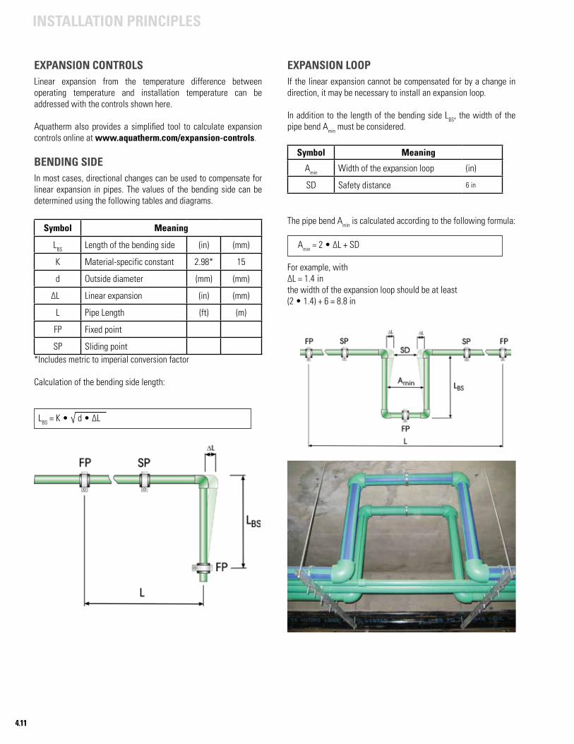
4.11
INSTALLATION PRINCIPLES
EXPANSION CONTROLSLinear expansion from the temperature difference between operating temperature and installation temperature can be addressed with the controls shown here.
Aquatherm also provides a simplified tool to calculate expansion controls online at www.aquatherm.com/expansion-controls.
BENDING SIDEIn most cases, directional changes can be used to compensate for linear expansion in pipes. The values of the bending side can be determined using the following tables and diagrams.
Symbol Meaning
LBS Length of the bending side (in) (mm)
K Material-specific constant 2.98* 15
d Outside diameter (mm) (mm)
∆L Linear expansion (in) (mm)
L Pipe Length (ft) (m)
FP Fixed point
SP Sliding point*Includes metric to imperial conversion factor
Calculation of the bending side length:
LBS = K • √ d • ∆L
EXPANSION LOOPIf the linear expansion cannot be compensated for by a change in direction, it may be necessary to install an expansion loop.
In addition to the length of the bending side LBS, the width of the pipe bend Amin must be considered.
Symbol Meaning
Amin Width of the expansion loop (in)
SD Safety distance 6 in
The pipe bend Amin is calculated according to the following formula: Amin = 2 • ∆L + SD
For example, with ∆L = 1.4 in the width of the expansion loop should be at least (2 • 1.4) + 6 = 8.8 in
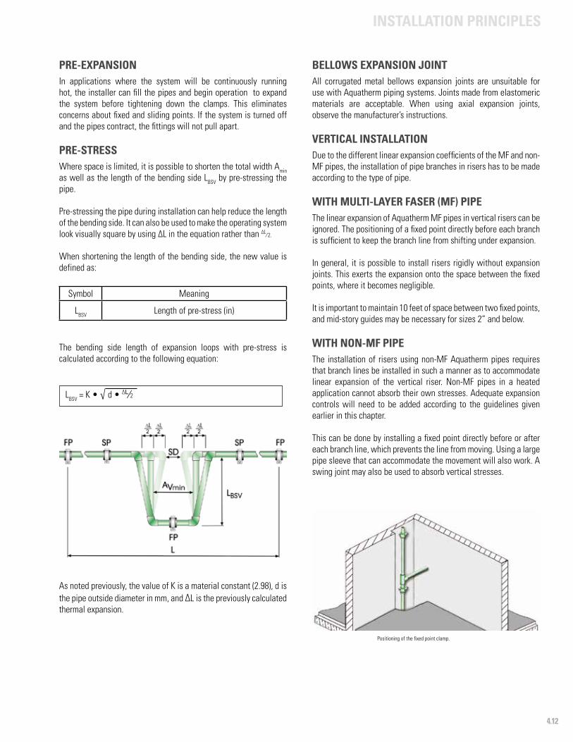
4.12
INSTALLATION PRINCIPLES
Positioning of the fixed point clamp.
PRE-EXPANSIONIn applications where the system will be continuously running hot, the installer can fill the pipes and begin operation to expand the system before tightening down the clamps. This eliminates concerns about fixed and sliding points. If the system is turned off and the pipes contract, the fittings will not pull apart.
PRE-STRESSWhere space is limited, it is possible to shorten the total width Amin as well as the length of the bending side LBSV by pre-stressing the pipe.
Pre-stressing the pipe during installation can help reduce the length of the bending side. It can also be used to make the operating system look visually square by using ∆L in the equation rather than ∆L⁄ 2.
When shortening the length of the bending side, the new value is defined as:
Symbol Meaning
LBSV Length of pre-stress (in)
The bending side length of expansion loops with pre-stress is calculated according to the following equation:
LBSV = K • √ d • ∆L⁄2
As noted previously, the value of K is a material constant (2.98), d is the pipe outside diameter in mm, and ∆L is the previously calculated thermal expansion.
BELLOWS EXPANSION JOINTAll corrugated metal bellows expansion joints are unsuitable for use with Aquatherm piping systems. Joints made from elastomeric materials are acceptable. When using axial expansion joints, observe the manufacturer’s instructions.
VERTICAL INSTALLATIONDue to the different linear expansion coefficients of the MF and non-MF pipes, the installation of pipe branches in risers has to be made according to the type of pipe.
WITH MULTI-LAYER FASER (MF) PIPEThe linear expansion of Aquatherm MF pipes in vertical risers can be ignored. The positioning of a fixed point directly before each branch is sufficient to keep the branch line from shifting under expansion.
In general, it is possible to install risers rigidly without expansion joints. This exerts the expansion onto the space between the fixed points, where it becomes negligible.
It is important to maintain 10 feet of space between two fixed points, and mid-story guides may be necessary for sizes 2” and below.
WITH NON-MF PIPEThe installation of risers using non-MF Aquatherm pipes requires that branch lines be installed in such a manner as to accommodate linear expansion of the vertical riser. Non-MF pipes in a heated application cannot absorb their own stresses. Adequate expansion controls will need to be added according to the guidelines given earlier in this chapter.
This can be done by installing a fixed point directly before or after each branch line, which prevents the line from moving. Using a large pipe sleeve that can accommodate the movement will also work. A swing joint may also be used to absorb vertical stresses.
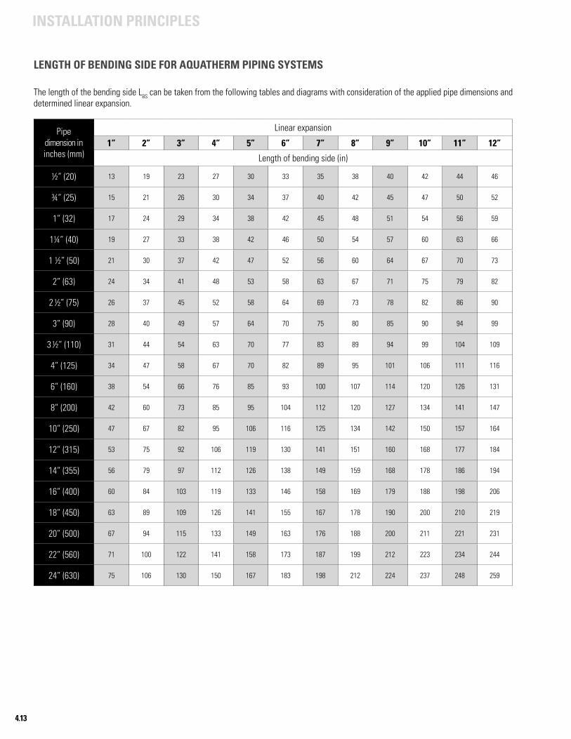
4.13
INSTALLATION PRINCIPLES
LENGTH OF BENDING SIDE FOR AQUATHERM PIPING SYSTEMS
The length of the bending side LBS can be taken from the following tables and diagrams with consideration of the applied pipe dimensions and determined linear expansion.
Pipe dimension in inches (mm)
Linear expansion
1” 2” 3” 4” 5” 6” 7” 8” 9” 10” 11” 12”
Length of bending side (in)
½” (20) 13 19 23 27 30 33 35 38 40 42 44 46
¾” (25) 15 21 26 30 34 37 40 42 45 47 50 52
1” (32) 17 24 29 34 38 42 45 48 51 54 56 59
1¼” (40) 19 27 33 38 42 46 50 54 57 60 63 66
1 ½” (50) 21 30 37 42 47 52 56 60 64 67 70 73
2” (63) 24 34 41 48 53 58 63 67 71 75 79 82
2 ½” (75) 26 37 45 52 58 64 69 73 78 82 86 90
3” (90) 28 40 49 57 64 70 75 80 85 90 94 99
3 ½” (110) 31 44 54 63 70 77 83 89 94 99 104 109
4” (125) 34 47 58 67 70 82 89 95 101 106 111 116
6” (160) 38 54 66 76 85 93 100 107 114 120 126 131
8” (200) 42 60 73 85 95 104 112 120 127 134 141 147
10” (250) 47 67 82 95 106 116 125 134 142 150 157 164
12” (315) 53 75 92 106 119 130 141 151 160 168 177 184
14” (355) 56 79 97 112 126 138 149 159 168 178 186 194
16” (400) 60 84 103 119 133 146 158 169 179 188 198 206
18” (450) 63 89 109 126 141 155 167 178 190 200 210 219
20” (500) 67 94 115 133 149 163 176 188 200 211 221 231
22” (560) 71 100 122 141 158 173 187 199 212 223 234 244
24” (630) 75 106 130 150 167 183 198 212 224 237 248 259
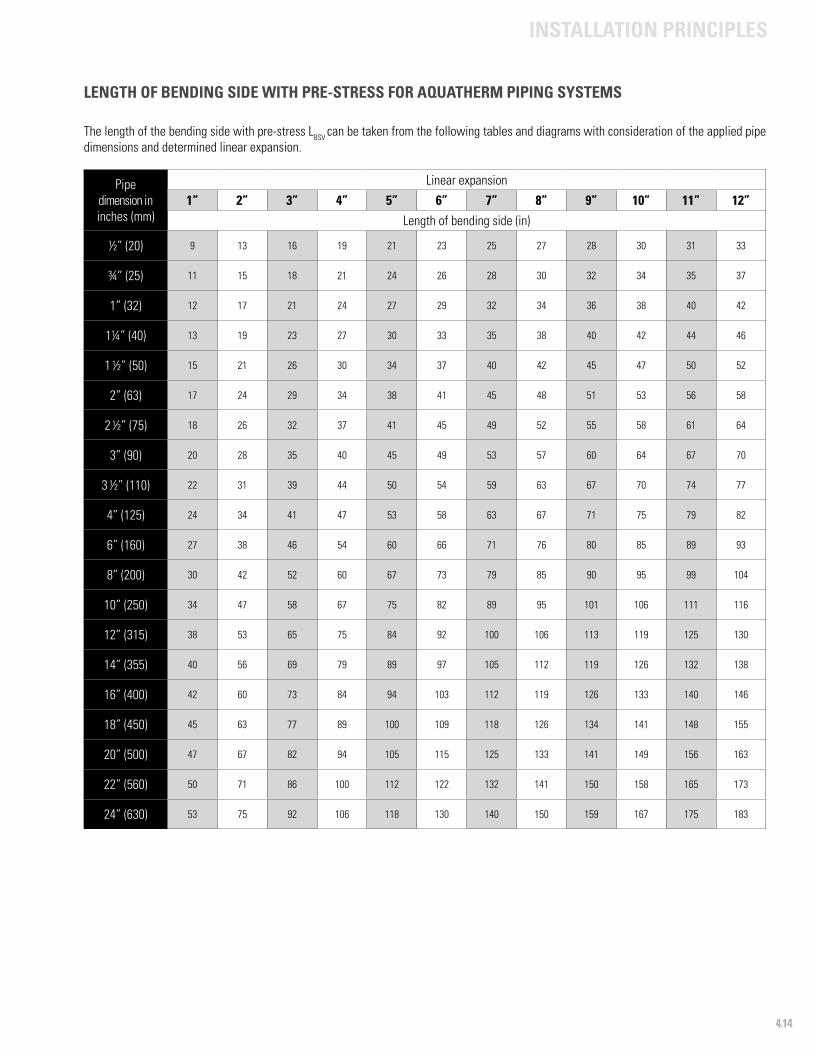
4.14
INSTALLATION PRINCIPLES
LENGTH OF BENDING SIDE WITH PRE-STRESS FOR AQUATHERM PIPING SYSTEMS
The length of the bending side with pre-stress LBSV can be taken from the following tables and diagrams with consideration of the applied pipe dimensions and determined linear expansion.
Pipe dimension in inches (mm)
Linear expansion
1” 2” 3” 4” 5” 6” 7” 8” 9” 10” 11” 12”
Length of bending side (in)
½” (20) 9 13 16 19 21 23 25 27 28 30 31 33
¾” (25) 11 15 18 21 24 26 28 30 32 34 35 37
1” (32) 12 17 21 24 27 29 32 34 36 38 40 42
1¼” (40) 13 19 23 27 30 33 35 38 40 42 44 46
1 ½” (50) 15 21 26 30 34 37 40 42 45 47 50 52
2” (63) 17 24 29 34 38 41 45 48 51 53 56 58
2 ½” (75) 18 26 32 37 41 45 49 52 55 58 61 64
3” (90) 20 28 35 40 45 49 53 57 60 64 67 70
3 ½” (110) 22 31 39 44 50 54 59 63 67 70 74 77
4” (125) 24 34 41 47 53 58 63 67 71 75 79 82
6” (160) 27 38 46 54 60 66 71 76 80 85 89 93
8” (200) 30 42 52 60 67 73 79 85 90 95 99 104
10” (250) 34 47 58 67 75 82 89 95 101 106 111 116
12” (315) 38 53 65 75 84 92 100 106 113 119 125 130
14” (355) 40 56 69 79 89 97 105 112 119 126 132 138
16” (400) 42 60 73 84 94 103 112 119 126 133 140 146
18” (450) 45 63 77 89 100 109 118 126 134 141 148 155
20” (500) 47 67 82 94 105 115 125 133 141 149 156 163
22” (560) 50 71 86 100 112 122 132 141 150 158 165 173
24” (630) 53 75 92 106 118 130 140 150 159 167 175 183
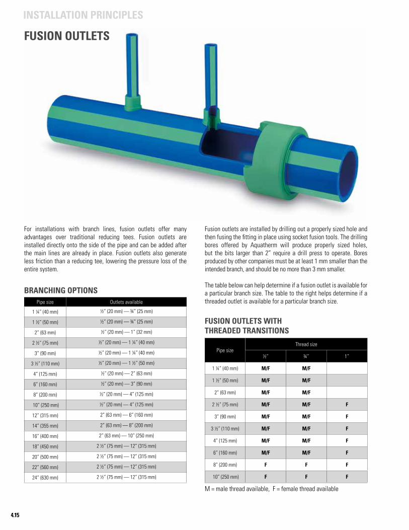
4.15
INSTALLATION PRINCIPLES
FUSION OUTLETS
Pipe sizeThread size
½” ¾” 1”
1 ¼” (40 mm) M/F M/F
1 ½” (50 mm) M/F M/F
2” (63 mm) M/F M/F
2 ½” (75 mm) M/F M/F F
3” (90 mm) M/F M/F F
3 ½” (110 mm) M/F M/F F
4” (125 mm) M/F M/F F
6” (160 mm) M/F M/F F
8” (200 mm) F F F
10” (250 mm) F F F
BRANCHING OPTIONS
FUSION OUTLETS WITHTHREADED TRANSITIONS
For installations with branch lines, fusion outlets offer many advantages over traditional reducing tees. Fusion outlets are installed directly onto the side of the pipe and can be added after the main lines are already in place. Fusion outlets also generate less friction than a reducing tee, lowering the pressure loss of the entire system.
M = male thread available, F = female thread available
Pipe size Outlets available
1 ¼” (40 mm) ½” (20 mm) — ¾” (25 mm)
1 ½” (50 mm) ½” (20 mm) — ¾” (25 mm)
2” (63 mm) ½” (20 mm) — 1” (32 mm)
2 ½” (75 mm) ½” (20 mm) — 1 ¼” (40 mm)
3” (90 mm) ½” (20 mm) — 1 ¼” (40 mm)
3 ½” (110 mm) ½” (20 mm) — 1 ½” (50 mm)
4” (125 mm) ½” (20 mm) — 2” (63 mm)
6” (160 mm) ½” (20 mm) — 3” (90 mm)
8” (200 mm) ½” (20 mm) — 4” (125 mm)
10” (250 mm) ½” (20 mm) — 4” (125 mm)
12” (315 mm) 2” (63 mm) — 6” (160 mm)
14” (355 mm) 2” (63 mm) — 8” (200 mm)
16” (400 mm) 2” (63 mm) — 10” (250 mm)
18” (450 mm) 2 ½” (75 mm) — 12” (315 mm)
20” (500 mm) 2 ½” (75 mm) — 12” (315 mm)
22” (560 mm) 2 ½” (75 mm) — 12” (315 mm)
24” (630 mm) 2 ½” (75 mm) — 12” (315 mm)
Fusion outlets are installed by drilling out a properly sized hole and then fusing the fitting in place using socket fusion tools. The drilling bores offered by Aquatherm will produce properly sized holes, but the bits larger than 2” require a drill press to operate. Bores produced by other companies must be at least 1 mm smaller than the intended branch, and should be no more than 3 mm smaller.
The table below can help determine if a fusion outlet is available for a particular branch size. The table to the right helps determine if a threaded outlet is available for a particular branch size.
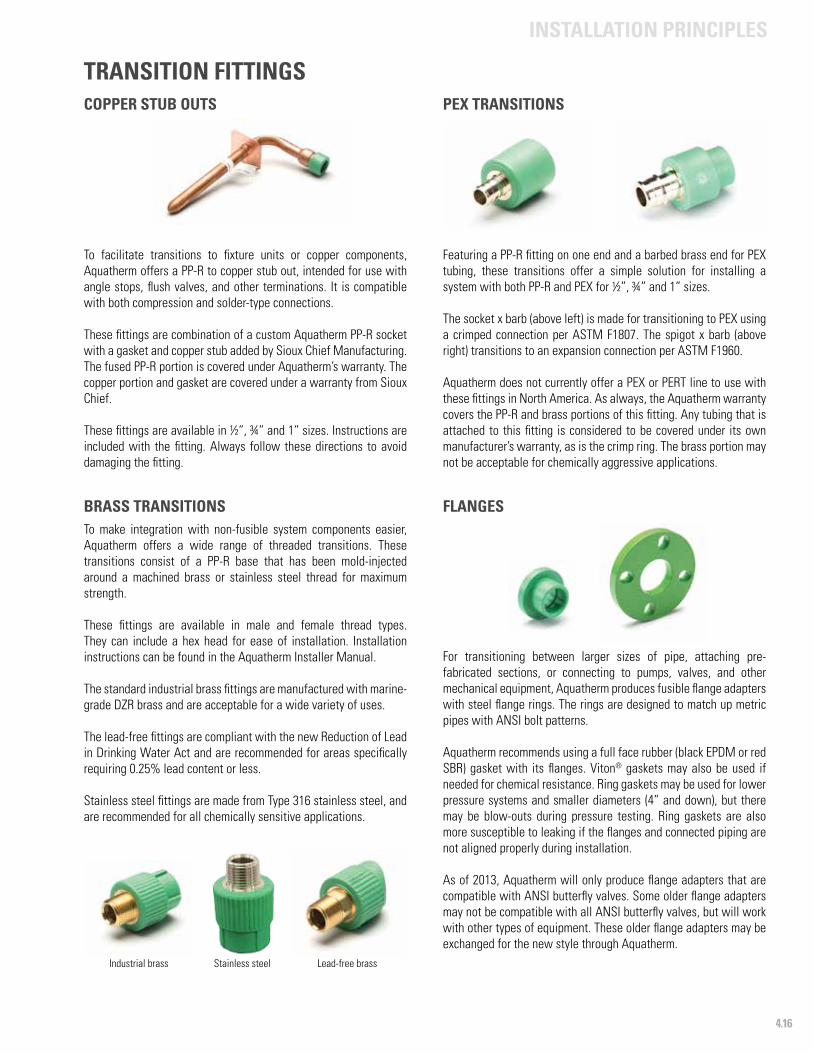
4.16
INSTALLATION PRINCIPLES
COPPER STUB OUTS
To facilitate transitions to fixture units or copper components, Aquatherm offers a PP-R to copper stub out, intended for use with angle stops, flush valves, and other terminations. It is compatible with both compression and solder-type connections.
These fittings are combination of a custom Aquatherm PP-R socket with a gasket and copper stub added by Sioux Chief Manufacturing. The fused PP-R portion is covered under Aquatherm’s warranty. The copper portion and gasket are covered under a warranty from Sioux Chief.
These fittings are available in ½”, ¾” and 1” sizes. Instructions are included with the fitting. Always follow these directions to avoid damaging the fitting.
PEX TRANSITIONS
Featuring a PP-R fitting on one end and a barbed brass end for PEX tubing, these transitions offer a simple solution for installing a system with both PP-R and PEX for ½”, ¾” and 1” sizes.
The socket x barb (above left) is made for transitioning to PEX using a crimped connection per ASTM F1807. The spigot x barb (above right) transitions to an expansion connection per ASTM F1960.
Aquatherm does not currently offer a PEX or PERT line to use with these fittings in North America. As always, the Aquatherm warranty covers the PP-R and brass portions of this fitting. Any tubing that is attached to this fitting is considered to be covered under its own manufacturer’s warranty, as is the crimp ring. The brass portion may not be acceptable for chemically aggressive applications.
TRANSITION FITTINGS
BRASS TRANSITIONS To make integration with non-fusible system components easier, Aquatherm offers a wide range of threaded transitions. These transitions consist of a PP-R base that has been mold-injected around a machined brass or stainless steel thread for maximum strength.
These fittings are available in male and female thread types. They can include a hex head for ease of installation. Installation instructions can be found in the Aquatherm Installer Manual.
The standard industrial brass fittings are manufactured with marine-grade DZR brass and are acceptable for a wide variety of uses.
The lead-free fittings are compliant with the new Reduction of Lead in Drinking Water Act and are recommended for areas specifically requiring 0.25% lead content or less.
Stainless steel fittings are made from Type 316 stainless steel, and are recommended for all chemically sensitive applications.
For transitioning between larger sizes of pipe, attaching pre-fabricated sections, or connecting to pumps, valves, and other mechanical equipment, Aquatherm produces fusible flange adapters with steel flange rings. The rings are designed to match up metric pipes with ANSI bolt patterns.
Aquatherm recommends using a full face rubber (black EPDM or red SBR) gasket with its flanges. Viton® gaskets may also be used if needed for chemical resistance. Ring gaskets may be used for lower pressure systems and smaller diameters (4” and down), but there may be blow-outs during pressure testing. Ring gaskets are also more susceptible to leaking if the flanges and connected piping are not aligned properly during installation.
As of 2013, Aquatherm will only produce flange adapters that are compatible with ANSI butterfly valves. Some older flange adapters may not be compatible with all ANSI butterfly valves, but will work with other types of equipment. These older flange adapters may be exchanged for the new style through Aquatherm.
Stainless steel Lead-free brassIndustrial brass
FLANGES
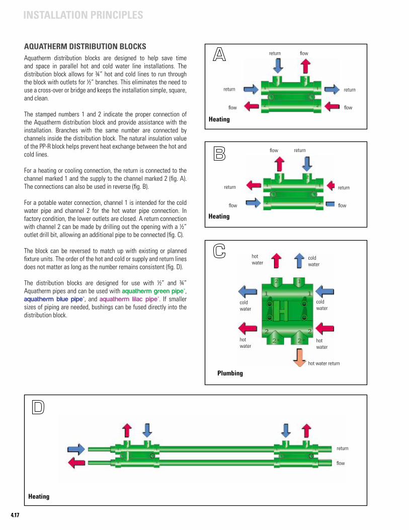
4.17
INSTALLATION PRINCIPLES
AQUATHERM DISTRIBUTION BLOCKSAquatherm distribution blocks are designed to help save time and space in parallel hot and cold water line installations. The distribution block allows for ¾” hot and cold lines to run through the block with outlets for ½” branches. This eliminates the need to use a cross-over or bridge and keeps the installation simple, square, and clean.
The stamped numbers 1 and 2 indicate the proper connection of the Aquatherm distribution block and provide assistance with the installation. Branches with the same number are connected by channels inside the distribution block. The natural insulation value of the PP-R block helps prevent heat exchange between the hot and cold lines.
For a heating or cooling connection, the return is connected to the channel marked 1 and the supply to the channel marked 2 (fig. A). The connections can also be used in reverse (fig. B).
For a potable water connection, channel 1 is intended for the cold water pipe and channel 2 for the hot water pipe connection. In factory condition, the lower outlets are closed. A return connection with channel 2 can be made by drilling out the opening with a ½” outlet drill bit, allowing an additional pipe to be connected (fig. C).
The block can be reversed to match up with existing or planned fixture units. The order of the hot and cold or supply and return lines does not matter as long as the number remains consistent (fig. D).
The distribution blocks are designed for use with ½” and ¾” Aquatherm pipes and can be used with aquatherm green pipe®, aquatherm blue pipe®, and aquatherm lilac pipe®. If smaller sizes of piping are needed, bushings can be fused directly into the distribution block.
Heating
flow flow
flowreturn
return return
hotwater
hotwater
hotwater
coldwater
coldwater
coldwater
hot water return
Plumbing
Heating
flow flow
flow return
return return
return
flow
Heating
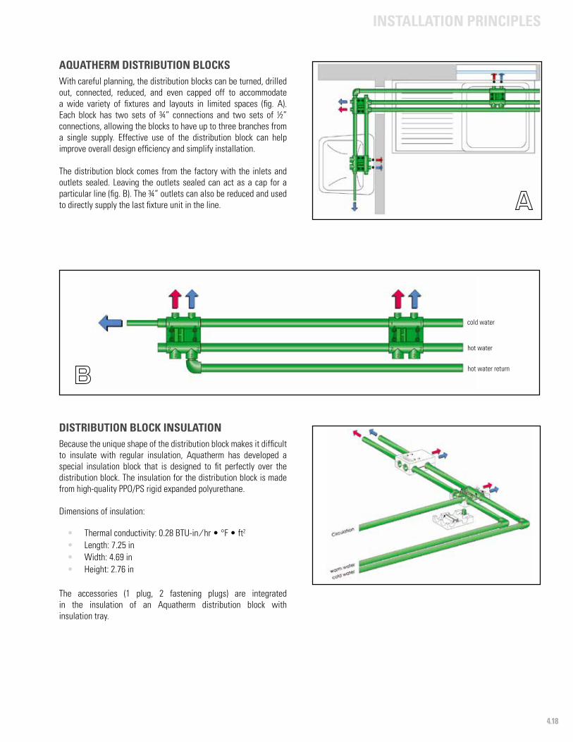
4.18
INSTALLATION PRINCIPLES
AQUATHERM DISTRIBUTION BLOCKSWith careful planning, the distribution blocks can be turned, drilled out, connected, reduced, and even capped off to accommodate a wide variety of fixtures and layouts in limited spaces (fig. A). Each block has two sets of ¾” connections and two sets of ½” connections, allowing the blocks to have up to three branches from a single supply. Effective use of the distribution block can help improve overall design efficiency and simplify installation.
The distribution block comes from the factory with the inlets and outlets sealed. Leaving the outlets sealed can act as a cap for a particular line (fig. B). The ¾” outlets can also be reduced and used to directly supply the last fixture unit in the line.
DISTRIBUTION BLOCK INSULATIONBecause the unique shape of the distribution block makes it difficult to insulate with regular insulation, Aquatherm has developed a special insulation block that is designed to fit perfectly over the distribution block. The insulation for the distribution block is made from high-quality PPO/PS rigid expanded polyurethane.
Dimensions of insulation:
• Thermal conductivity: 0.28 BTU-in ⁄ hr • °F • ft2
• Length: 7.25 in• Width: 4.69 in• Height: 2.76 in
The accessories (1 plug, 2 fastening plugs) are integrated in the insulation of an Aquatherm distribution block with insulation tray.
hot water
cold water
hot water return
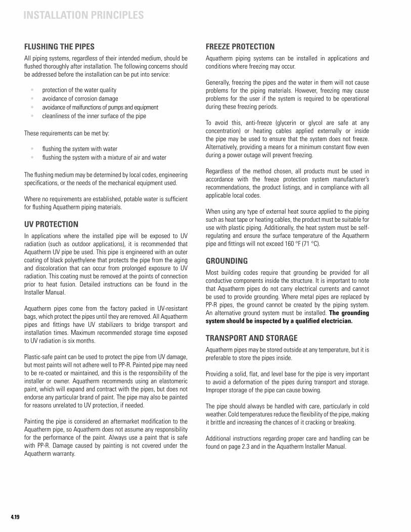
4.19
INSTALLATION PRINCIPLES
FLUSHING THE PIPESAll piping systems, regardless of their intended medium, should be flushed thoroughly after installation. The following concerns should be addressed before the installation can be put into service:
• protection of the water quality• avoidance of corrosion damage• avoidance of malfunctions of pumps and equipment• cleanliness of the inner surface of the pipe
These requirements can be met by:
• flushing the system with water• flushing the system with a mixture of air and water
The flushing medium may be determined by local codes, engineering specifications, or the needs of the mechanical equipment used.
Where no requirements are established, potable water is sufficient for flushing Aquatherm piping materials.
UV PROTECTIONIn applications where the installed pipe will be exposed to UV radiation (such as outdoor applications), it is recommended that Aquatherm UV pipe be used. This pipe is engineered with an outer coating of black polyethylene that protects the pipe from the aging and discoloration that can occur from prolonged exposure to UV radiation. This coating must be removed at the points of connection prior to heat fusion. Detailed instructions can be found in the Installer Manual.
Aquatherm pipes come from the factory packed in UV-resistant bags, which protect the pipes until they are removed. All Aquatherm pipes and fittings have UV stabilizers to bridge transport and installation times. Maximum recommended storage time exposed to UV radiation is six months.
Plastic-safe paint can be used to protect the pipe from UV damage, but most paints will not adhere well to PP-R. Painted pipe may need to be re-coated or maintained, and this is the responsibility of the installer or owner. Aquatherm recommends using an elastomeric paint, which will expand and contract with the pipes, but does not endorse any particular brand of paint. The pipe may also be painted for reasons unrelated to UV protection, if needed.
Painting the pipe is considered an aftermarket modification to the Aquatherm pipe, so Aquatherm does not assume any responsibility for the performance of the paint. Always use a paint that is safe with PP-R. Damage caused by painting is not covered under the Aquatherm warranty.
FREEZE PROTECTIONAquatherm piping systems can be installed in applications and conditions where freezing may occur.
Generally, freezing the pipes and the water in them will not cause problems for the piping materials. However, freezing may cause problems for the user if the system is required to be operational during these freezing periods.
To avoid this, anti-freeze (glycerin or glycol are safe at any concentration) or heating cables applied externally or inside the pipe may be used to ensure that the system does not freeze. Alternatively, providing a means for a minimum constant flow even during a power outage will prevent freezing.
Regardless of the method chosen, all products must be used in accordance with the freeze protection system manufacturer’s recommendations, the product listings, and in compliance with all applicable local codes.
When using any type of external heat source applied to the piping such as heat tape or heating cables, the product must be suitable for use with plastic piping. Additionally, the heat system must be self-regulating and ensure the surface temperature of the Aquatherm pipe and fittings will not exceed 160 °F (71 °C).
GROUNDINGMost building codes require that grounding be provided for all conductive components inside the structure. It is important to note that Aquatherm pipes do not carry electrical currents and cannot be used to provide grounding. Where metal pipes are replaced by PP-R pipes, the ground cannot be created by the piping system. An alternative ground system must be installed. The grounding system should be inspected by a qualified electrician.
TRANSPORT AND STORAGEAquatherm pipes may be stored outside at any temperature, but it is preferable to store the pipes inside.
Providing a solid, flat, and level base for the pipe is very important to avoid a deformation of the pipes during transport and storage. Improper storage of the pipe can cause bowing.
The pipe should always be handled with care, particularly in cold weather. Cold temperatures reduce the flexibility of the pipe, making it brittle and increasing the chances of it cracking or breaking.
Additional instructions regarding proper care and handling can be found on page 2.3 and in the Aquatherm Installer Manual.

4.20
INSTALLATION PRINCIPLES
PRESSURE TEST In order to ensure that an installed system is prepared for service, a pressure test is highly encouraged. A properly administered test will pressurize the system via several cycles in order to identify any improper fusions that could disrupt system operation in the future.
While still accessible, all pipelines must be pressure tested using water, air, or a mix of the two.
The pressure test consists of a preliminary, principal, and final test. For more information, the pressure test procedure and test record are provided at www.aquatherm.com/pressure-test-form.
Note: The online instructions are kept up to date and take precedence over any information provided in this catalog concerning the pressure test.
TEST RECORDA record of the pressure test must be prepared and signed by the client and contractor stating place, contractor installer number (found on the training certificate), and date. For an example, see the following page. A system can be tested in phases provided that every heat-fused connection is eventually tested and that the tests are properly documented upon completion.
This test is designed to identify damaged pipe, manufacturer’s defects, and poor workmanship. It is required by the manufacturer for the validation of the Aquatherm warranty* from the date of install. This does not supersede or replace regulations placed by the local code authority having jurisdiction. To prevent back-dating, Aquatherm requires that this test be submitted before the system begins full operation.
Pressure test forms must be sent to Aquatherm:
• E-mail: [email protected]• Fax: 801-847-6554
* Aquatherm’s warranty does not cover failures caused by improper installation, operation outside of the recommended parameters, or damage from mishandling after the pipe has left possession of the manufacturer. Completing the pressure test does not guarantee coverage in the event of a failure caused by improper installation.
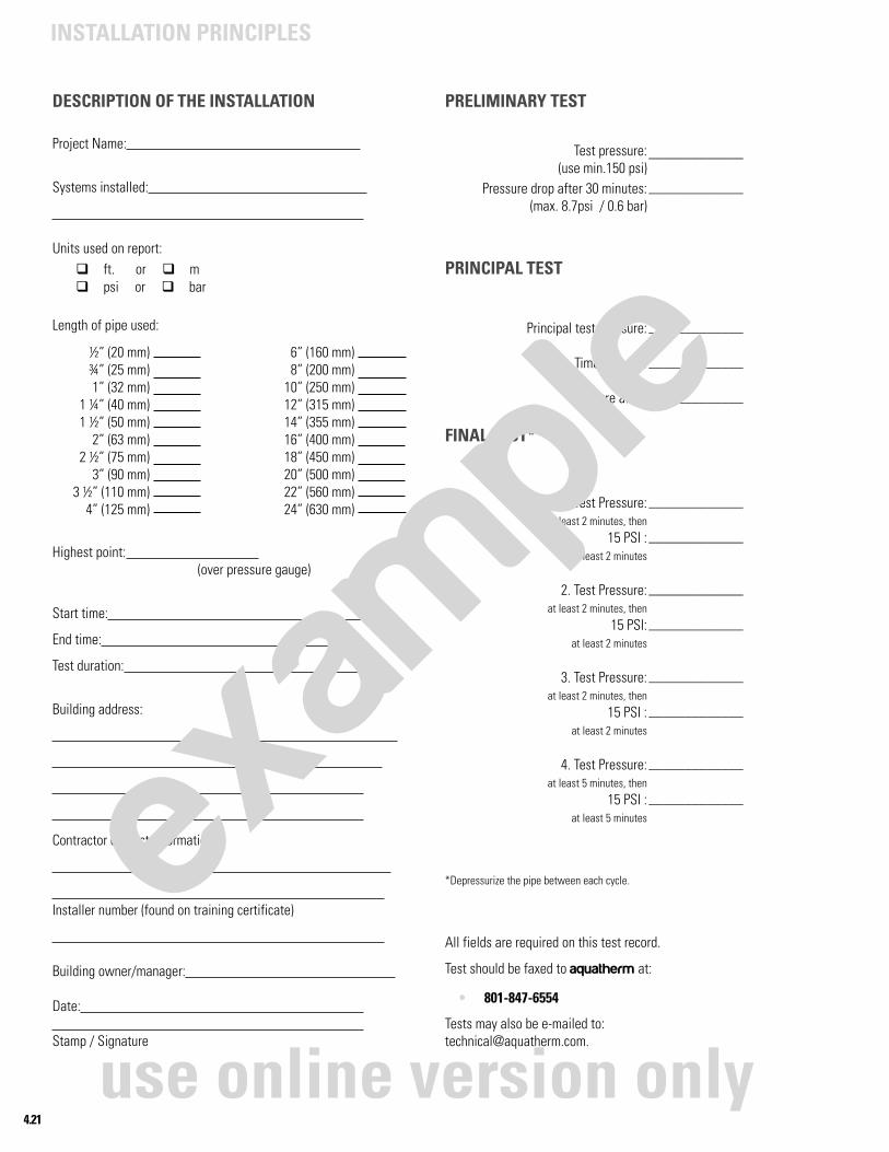
4.21
INSTALLATION PRINCIPLES
PRELIMINARY TEST
PRINCIPAL TEST
FINAL TEST*
*Depressurize the pipe between each cycle.
All fields are required on this test record.
Test should be faxed to aquatherm at:
• 801-847-6554
Tests may also be e-mailed to:[email protected].
DESCRIPTION OF THE INSTALLATION
Project Name:
Systems installed:
Units used on report:
Length of pipe used:
Highest point: (over pressure gauge)
Start time:
End time:
Test duration:
Building address:
Contractor contact information:
Installer number (found on training certificate)
Building owner/manager:
Date: Stamp / Signature
Test pressure:(use min.150 psi)
Pressure drop after 30 minutes: (max. 8.7psi / 0.6 bar)
Principal test pressure:
Time elapsed:
Pressure after:
1. Test Pressure: at least 2 minutes, then
15 PSI : at least 2 minutes
2. Test Pressure: at least 2 minutes, then
15 PSI: at least 2 minutes
3. Test Pressure: at least 2 minutes, then
15 PSI : at least 2 minutes
4. Test Pressure: at least 5 minutes, then
15 PSI : at least 5 minutes
_____________
_____________
_____________
_____________
_____________
_____________
_____________
_____________
_____________
_____________
_____________
_____________
_____________
½” (20 mm)¾” (25 mm)1” (32 mm)
1 ¼” (40 mm)1 ½” (50 mm)
2” (63 mm)2 ½” (75 mm)
3” (90 mm)3 ½” (110 mm)
4” (125 mm)
6” (160 mm)8” (200 mm)
10” (250 mm)12” (315 mm)14” (355 mm)16” (400 mm)18” (450 mm)20” (500 mm)22” (560 mm)24” (630 mm)
q ft. or q mq psi or q bar
exam
ple
use online version only
aquatherm green pipe®
aquatherm blue pipe®
aquatherm lilac pipe®
Accessories
Fittings
Flanges
Couplings
PP-R to metal
Distributors
Valves
Tools
Note: Dimensional data for the fittings has been added to the NA edition Aquatherm catalog. However, due to the ongoing expansion and improvement of the Aquatherm line, the dimension data was not completed at the time of printing. The dimensional data here is derivative of other documents and should not be considered absolute. It is included in this catalog for the user’s convenience. If an error is found between this chapter and an actual part, please inform Aquatherm so that this, and the documents it derives from, can be updated and corrected.
PRODUCT RANGE5
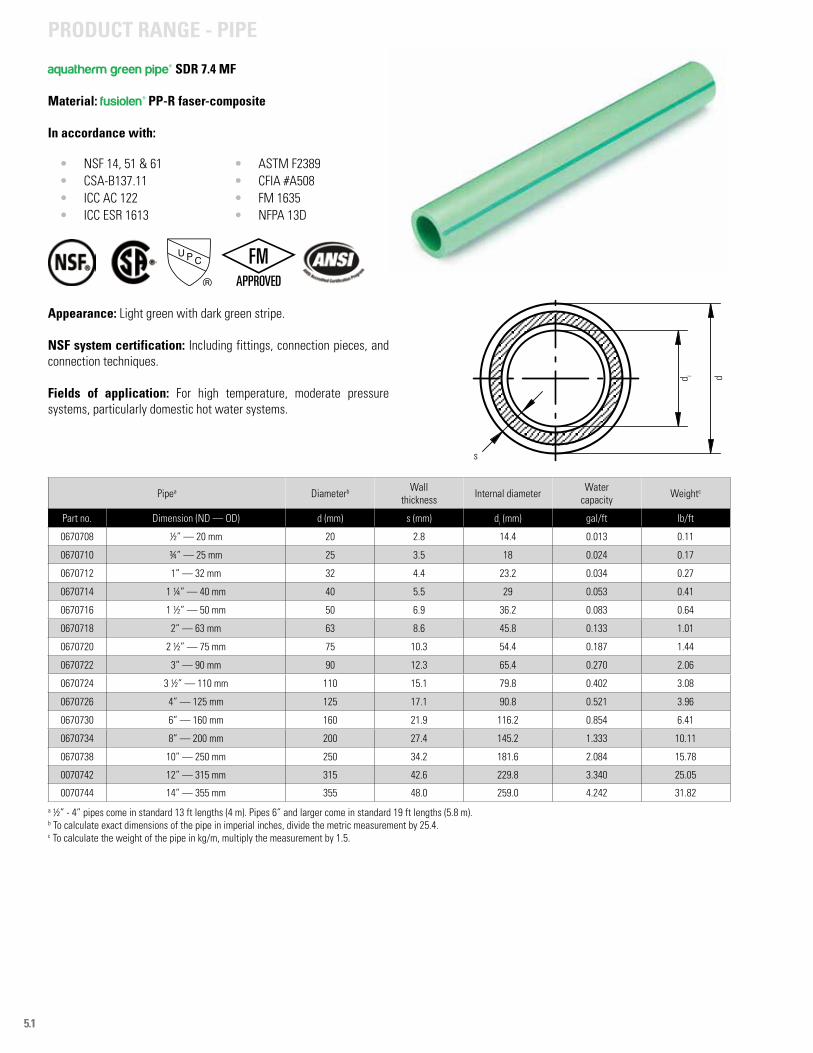
5.1
aquatherm green pipe® SDR 7.4 MF
Material: fusiolen® PP-R faser-composite
In accordance with:
• NSF 14, 51 & 61• CSA-B137.11• ICC AC 122 • ICC ESR 1613
• ASTM F2389• CFIA #A508• FM 1635 • NFPA 13D
Appearance: Light green with dark green stripe.
NSF system certification: Including fittings, connection pieces, and connection techniques.
Fields of application: For high temperature, moderate pressure systems, particularly domestic hot water systems.
Pipea Diameterb Wall thickness Internal diameter Water
capacity Weightc
Part no. Dimension (ND — OD) d (mm) s (mm) di (mm) gal/ft lb/ft
0670708 ½” — 20 mm 20 2.8 14.4 0.013 0.11
0670710 ¾” — 25 mm 25 3.5 18 0.024 0.17
0670712 1” — 32 mm 32 4.4 23.2 0.034 0.27
0670714 1 ¼” — 40 mm 40 5.5 29 0.053 0.41
0670716 1 ½” — 50 mm 50 6.9 36.2 0.083 0.64
0670718 2” — 63 mm 63 8.6 45.8 0.133 1.01
0670720 2 ½” — 75 mm 75 10.3 54.4 0.187 1.44
0670722 3” — 90 mm 90 12.3 65.4 0.270 2.06
0670724 3 ½” — 110 mm 110 15.1 79.8 0.402 3.08
0670726 4” — 125 mm 125 17.1 90.8 0.521 3.96
0670730 6” — 160 mm 160 21.9 116.2 0.854 6.41
0670734 8” — 200 mm 200 27.4 145.2 1.333 10.11
0670738 10” — 250 mm 250 34.2 181.6 2.084 15.78
0070742 12” — 315 mm 315 42.6 229.8 3.340 25.05
0070744 14” — 355 mm 355 48.0 259.0 4.242 31.82
a ½” - 4” pipes come in standard 13 ft lengths (4 m). Pipes 6” and larger come in standard 19 ft lengths (5.8 m).b To calculate exact dimensions of the pipe in imperial inches, divide the metric measurement by 25.4.c To calculate the weight of the pipe in kg/m, multiply the measurement by 1.5.
d i d
s
PRODUCT RANGE - PIPE
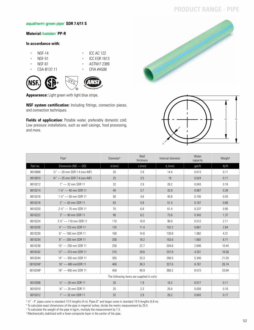
5.2
aquatherm green pipe® SDR 7.4/11 S
Material: fusiolen® PP-R
In accordance with:
• NSF-14• NSF-51• NSF-61• CSA-B137.11
• ICC AC 122 • ICC ESR 1613• ASTM F 2389• CFIA #A508
Appearance: Light green with light blue stripe.
NSF system certification: Including fittings, connection pieces, and connection techniques.
Fields of application: Potable water, preferably domestic cold. Low pressure installations, such as well casings, food processing, and more.
Pipea Diameterb Wall thickness Internal diameter Water
capacity Weightc
Part no. Dimension (ND — OD) d (mm) s (mm) di (mm) gal/ft lb/ft
0610808 ½” — 20 mm SDR 7.4 (non-MF) 20 2.8 14.4 0.013 0.11
0610810 ¾” — 25 mm SDR 7.4 (non-MF) 25 3.5 18 0.024 0.17
0610212 1” — 32 mm SDR 11 32 2.9 26.2 0.043 0.18
0610214 1 ¼” — 40 mm SDR 11 40 3.7 32.6 0.067 0.28
0610216 1 ½” — 50 mm SDR 11 50 4.6 40.8 0.105 0.43
0610218 2” — 63 mm SDR 11 63 5.8 51.4 0.167 0.68
0610220 2 ½” — 75 mm SDR 11 75 6.8 61.4 0.237 0.95
0610222 3” — 90 mm SDR 11 90 8.2 73.6 0.343 1.37
0610224 3 ½” — 110 mm SDR 11 110 10.0 90.0 0.512 2.11
0610226 4” — 125 mm SDR 11 125 11.4 102.2 0.661 2.64
0610230 6” — 160 mm SDR 11 160 14.6 130.8 1.082 4.31
0610234 8” — 200 mm SDR 11 200 18.2 163.6 1.692 6.71
0610238 10” — 250 mm SDR 11 250 22.7 204.6 2.646 10.44
0010242 12” — 315 mm SDR 11 315 28.6 257.8 4.201 16.56
0010244 14” — 355 mm SDR 11 355 33.3 290.5 5.340 21.03
0010246d 16” — 400 mmSDR 11 400 36.3 327.6 6.787 26.74
0010248d 18” — 450 mm SDR 11 450 40.9 368.2 8.573 33.84
The following items are supplied in coils:
0010308 ½” — 20 mm SDR 11 20 1.9 16.2 0.017 0.11
0010310 ¾” — 25 mm SDR 11 25 2.3 20.4 0.026 0.16
0010312 1” — 32 mm SDR 11 32 2.9 26.2 0.043 0.17
a ½” - 4” pipes come in standard 13 ft lengths (4 m). Pipes 6” and larger come in standard 19 ft lengths (5.8 m).b To calculate exact dimensions of the pipe in imperial inches, divide the metric measurement by 25.4.c To calculate the weight of the pipe in kg/m, multiply the measurement by 1.5.d Mechanically stabilized with a faser-composite layer in the center of the pipe.
s
d i d
PRODUCT RANGE - PIPE
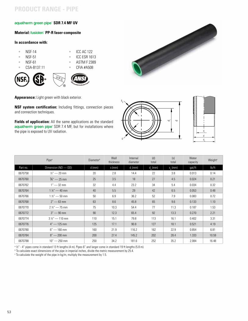
5.3
aquatherm green pipe® SDR 7.4 MF UV
Material: fusiolen® PP-R faser-composite
In accordance with:
• NSF-14• NSF-51• NSF-61• CSA-B137.11
• ICC AC 122 • ICC ESR 1613• ASTM F 2389• CFIA #A508
Appearance: Light green with black exterior.
NSF system certification: Including fittings, connection pieces and connection techniques.
Fields of application: All the same applications as the standard aquatherm green pipe® SDR 7.4 MF, but for installations where the pipe is exposed to UV radiation.
Pipea Diameterb Wall thickness
Internal diameter
(d)total
(s)total
Water capacity Weightc
Part no. Dimension (ND — OD) d (mm) s (mm) di (mm) dg (mm) sg (mm) gal/ft lb/ft
0670758 ½” — 20 mm 20 2.8 14.4 22 3.8 0.013 0.14
0670760 ¾” — 25 mm 25 3.5 18 27 4.5 0.024 0.21
0670762 1” — 32 mm 32 4.4 23.2 34 5.4 0.034 0.32
0670764 1 ¼” — 40 mm 40 5.5 29 42 6.5 0.053 0.48
0670766 1 ½” — 50 mm 50 6.9 36.2 52 7.9 0.083 0.72
0670768 2” — 63 mm 63 8.6 45.8 65 9.6 0.133 1.10
0670770 2 ½” — 75 mm 75 10.3 54.4 77 11.3 0.187 1.53
0670772 3” — 90 mm 90 12.3 65.4 92 13.3 0.270 2.21
0670774 3 ½” — 110 mm 110 15.1 79.8 113 16.1 0.402 3.31
0670776 4” — 125 mm 125 17.1 90.8 127 18.1 0.521 4.19
0670780 6” — 160 mm 160 21.9 116.2 162 22.9 0.854 6.81
0670784 8” — 200 mm 200 27.4 145.2 202 28.4 1.333 10.59
0670788 10” — 250 mm 250 34.2 181.6 252 35.2 2.084 16.48
a ½” - 4” pipes come in standard 13 ft lengths (4 m). Pipes 6” and larger come in standard 19 ft lengths (5.8 m).b To calculate exact dimensions of the pipe in imperial inches, divide the metric measurement by 25.4.c To calculate the weight of the pipe in kg/m, multiply the measurement by 1.5.
di
ddg
sg
s
d i d
PRODUCT RANGE - PIPE
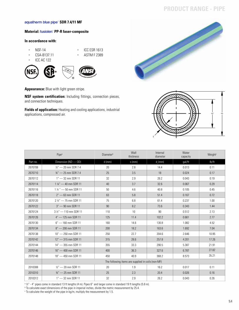
5.4
aquatherm blue pipe® SDR 7.4/11 MF
Material: fusiolen® PP-R faser-composite
In accordance with:
• NSF-14• CSA-B137.11• ICC AC 122
• ICC ESR 1613• ASTM F 2389
Appearance: Blue with light green stripe.
NSF system certification: Including fittings, connection pieces, and connection techniques.
Fields of application: Heating and cooling applications, industrial applications, compressed air.
Pipea Diameterb Wall thickness
Internal diameter
Water capacity Weightc
Part no. Dimension (ND — OD) d (mm) s (mm) di (mm) gal/ft lb/ft
2670708 ½” — 20 mm SDR 7.4 20 2.8 14.4 0.013 0.11
2670710 ¾” — 25 mm SDR 7.4 25 3.5 18 0.024 0.17
2670112 1” — 32 mm SDR 11 32 2.9 26.2 0.043 0.19
2670114 1 ¼” — 40 mm SDR 11 40 3.7 32.6 0.067 0.29
2670116 1 ½ ” — 50 mm SDR 11 50 4.6 40.8 0.105 0.45
2670118 2” — 63 mm SDR 11 63 5.8 51.4 0.167 0.72
2670120 2 ½” — 75 mm SDR 11 75 6.8 61.4 0.237 1.00
2670122 3” — 90 mm SDR 11 90 8.2 73.6 0.343 1.44
2670124 3 ½” — 110 mm SDR 11 110 10 90 0.512 2.13
2670126 4” — 125 mm SDR 11 125 11.4 102.2 0.661 2.77
2670130 6” — 160 mm SDR 11 160 14.6 130.8 1.082 4.52
2670134 8” — 200 mm SDR 11 200 18.2 163.6 1.692 7.04
2670138 10” — 250 mm SDR 11 250 22.7 204.6 2.646 10.95
2070142 12” — 315 mm SDR 11 315 28.6 257.8 4.201 17.26
2070144 14” — 355 mm SDR 11 355 33.3 290.5 5.387 21.91
2070146 16” — 400 mm SDR 11 400 36.3 327.6 6.787 27.82
2070148 18” — 450 mm SDR 11 450 40.9 368.2 8.573 35.21
The following items are supplied in coils (non-MF)
2010308 ½” — 20 mm SDR 11 20 1.9 16.2 0.017 0.11
2010310 ¾” — 25 mm SDR 11 25 2.3 20.4 0.026 0.16
2010312 1” — 32 mm SDR 11 32 2.9 26.2 0.043 0.26
a ½” - 4” pipes come in standard 13 ft lengths (4 m). Pipes 6” and larger come in standard 19 ft lengths (5.8 m).b To calculate exact dimensions of the pipe in imperial inches, divide the metric measurement by 25.4.c To calculate the weight of the pipe in kg/m, multiply the measurement by 1.5.
s
d i d
PRODUCT RANGE - PIPE
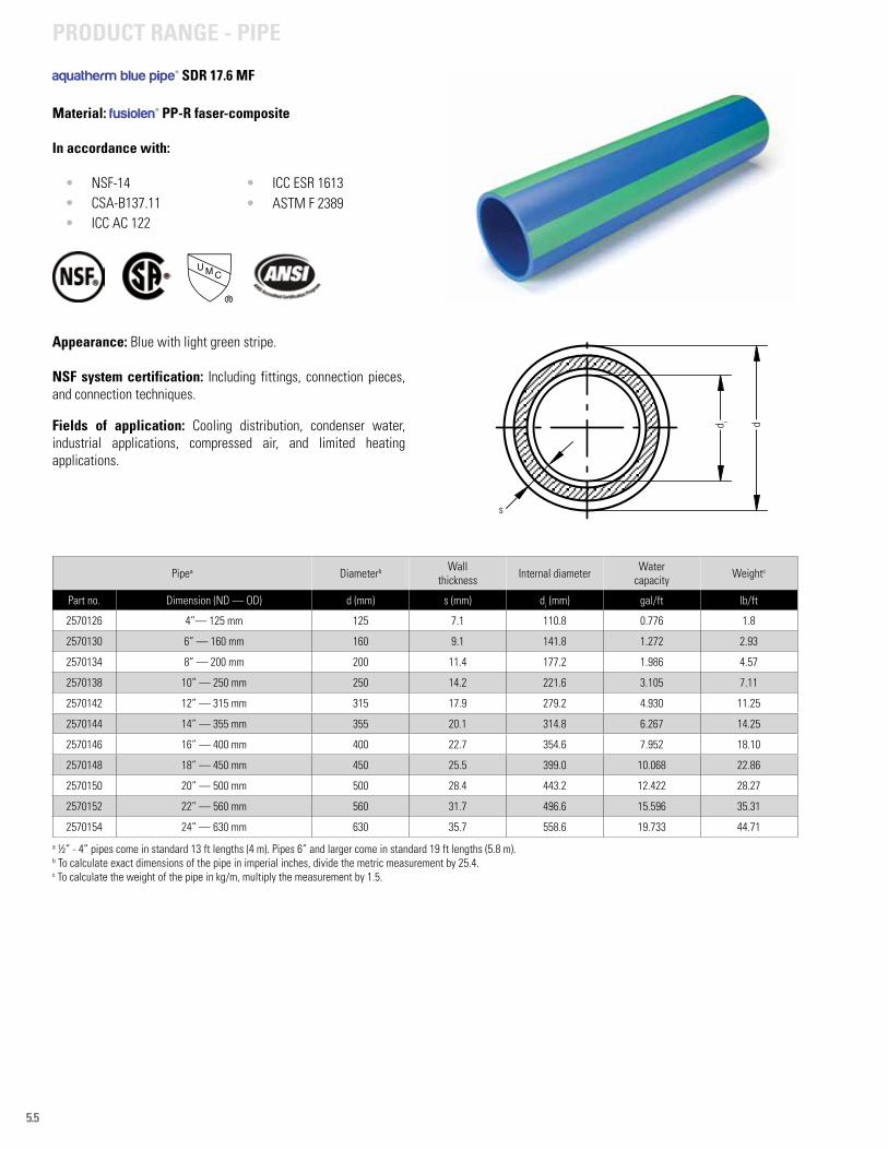
5.5
aquatherm blue pipe® SDR 17.6 MF
Material: fusiolen® PP-R faser-composite
In accordance with:
• NSF-14• CSA-B137.11• ICC AC 122
• ICC ESR 1613• ASTM F 2389
Appearance: Blue with light green stripe.
NSF system certification: Including fittings, connection pieces, and connection techniques.
Fields of application: Cooling distribution, condenser water, industrial applications, compressed air, and limited heating applications.
Pipea Diameterb Wall thickness Internal diameter Water
capacity Weightc
Part no. Dimension (ND — OD) d (mm) s (mm) di (mm) gal/ft lb/ft
2570126 4”— 125 mm 125 7.1 110.8 0.776 1.8
2570130 6” — 160 mm 160 9.1 141.8 1.272 2.93
2570134 8” — 200 mm 200 11.4 177.2 1.986 4.57
2570138 10” — 250 mm 250 14.2 221.6 3.105 7.11
2570142 12” — 315 mm 315 17.9 279.2 4.930 11.25
2570144 14” — 355 mm 355 20.1 314.8 6.267 14.25
2570146 16” — 400 mm 400 22.7 354.6 7.952 18.10
2570148 18” — 450 mm 450 25.5 399.0 10.068 22.86
2570150 20” — 500 mm 500 28.4 443.2 12.422 28.27
2570152 22” — 560 mm 560 31.7 496.6 15.596 35.31
2570154 24” — 630 mm 630 35.7 558.6 19.733 44.71
a ½” - 4” pipes come in standard 13 ft lengths (4 m). Pipes 6” and larger come in standard 19 ft lengths (5.8 m).b To calculate exact dimensions of the pipe in imperial inches, divide the metric measurement by 25.4.c To calculate the weight of the pipe in kg/m, multiply the measurement by 1.5.
s
d i d
PRODUCT RANGE - PIPE
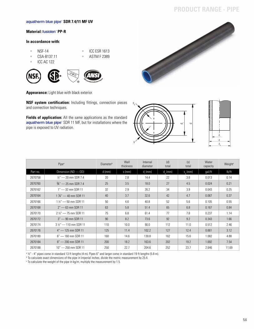
5.6
aquatherm blue pipe® SDR 7.4/11 MF UV
Material: fusiolen® PP-R
In accordance with:
• NSF-14• CSA-B137.11• ICC AC 122
• ICC ESR 1613• ASTM F 2389
Appearance: Light blue with black exterior.
NSF system certification: Including fittings, connection pieces and connection techniques.
Fields of application: All the same applications as the standard aquatherm blue pipe® SDR 11 MF, but for installations where the pipe is exposed to UV radiation.
Pipea Diameterb Wall thickness
Internal diameter
(d)total
(s)total
Water capacity Weightc
Part no. Dimension (ND — OD) d (mm) s (mm) di (mm) dg (mm) sg (mm) gal/ft lb/ft
2670758 ½” — 20 mm SDR 7.4 20 2.8 14.4 22 3.8 0.013 0.14
2670760 ¾” — 25 mm SDR 7.4 25 3.5 18.0 27 4.5 0.024 0.21
2670162 1” — 32 mm SDR 11 32 2.9 26.2 34 3.9 0.043 0.25
2670164 1 ¼” — 40 mm SDR 11 40 3.7 32.6 42 4.7 0.067 0.37
2670166 1 ½” — 50 mm SDR 11 50 4.6 40.8 52 5.6 0.105 0.55
2670168 2” — 63 mm SDR 11 63 5.8 51.4 65 6.8 0.167 0.84
2670170 2 ½” — 75 mm SDR 11 75 6.8 61.4 77 7.8 0.237 1.14
2670172 3” — 90 mm SDR 11 90 8.2 73.6 92 9.2 0.343 1.66
2670174 3 ½” — 110 mm SDR 11 110 10.0 90.0 112 11.0 0.512 2.46
2670176 4” — 125 mm SDR 11 125 11.4 102.2 127 12.4 0.661 3.12
2670180 6” — 160 mm SDR 11 160 14.6 130.8 162 15.6 1.082 4.88
2670184 8” — 200 mm SDR 11 200 18.2 163.6 202 19.2 1.692 7.54
2670188 10” — 250 mm SDR 11 250 22.7 204.6 252 23.7 2.646 11.69
a ½” - 4” pipes come in standard 13 ft lengths (4 m). Pipes 6” and larger come in standard 19 ft lengths (5.8 m).b To calculate exact dimensions of the pipe in imperial inches, divide the metric measurement by 25.4.c To calculate the weight of the pipe in kg/m, multiply the measurement by 1.5.
sg
s
d i d
di
ddg
PRODUCT RANGE - PIPE
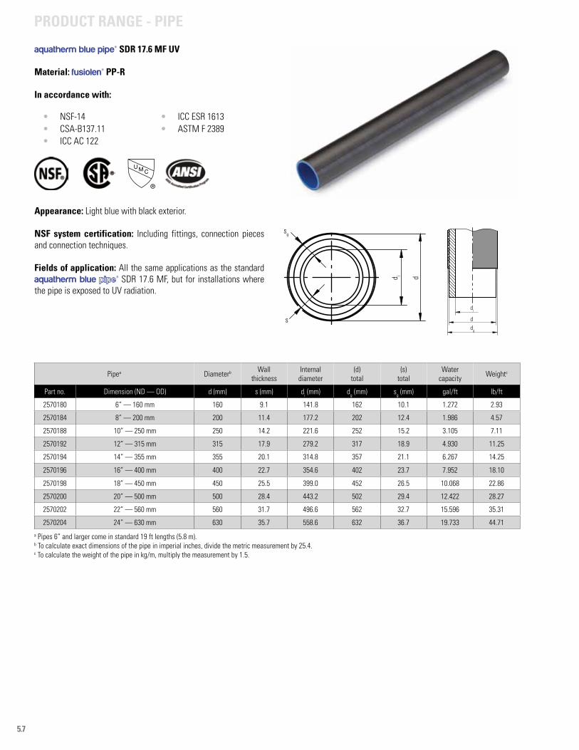
5.7
aquatherm blue pipe® SDR 17.6 MF UV
Material: fusiolen® PP-R
In accordance with:
• NSF-14• CSA-B137.11• ICC AC 122
• ICC ESR 1613• ASTM F 2389
Appearance: Light blue with black exterior.
NSF system certification: Including fittings, connection pieces and connection techniques.
Fields of application: All the same applications as the standard aquatherm blue ® SDR 17.6 MF, but for installations where the pipe is exposed to UV radiation.
a Pipes 6” and larger come in standard 19 ft lengths (5.8 m).b To calculate exact dimensions of the pipe in imperial inches, divide the metric measurement by 25.4.c To calculate the weight of the pipe in kg/m, multiply the measurement by 1.5.
sg
s
d i d
di
ddg
Pipea Diameterb Wall thickness
Internal diameter
(d)total
(s)total
Water capacity Weightc
Part no. Dimension (ND — OD) d (mm) s (mm) di (mm) dg (mm) sg (mm) gal/ft lb/ft
2570180 6” — 160 mm 160 9.1 141.8 162 10.1 1.272 2.93
2570184 8” — 200 mm 200 11.4 177.2 202 12.4 1.986 4.57
2570188 10” — 250 mm 250 14.2 221.6 252 15.2 3.105 7.11
2570192 12” — 315 mm 315 17.9 279.2 317 18.9 4.930 11.25
2570194 14” — 355 mm 355 20.1 314.8 357 21.1 6.267 14.25
2570196 16” — 400 mm 400 22.7 354.6 402 23.7 7.952 18.10
2570198 18” — 450 mm 450 25.5 399.0 452 26.5 10.068 22.86
2570200 20” — 500 mm 500 28.4 443.2 502 29.4 12.422 28.27
2570202 22” — 560 mm 560 31.7 496.6 562 32.7 15.596 35.31
2570204 24” — 630 mm 630 35.7 558.6 632 36.7 19.733 44.71
PRODUCT RANGE - PIPE
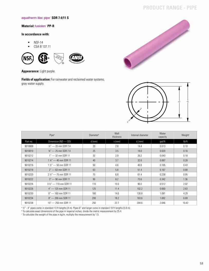
5.8
aquatherm lilac pipe® SDR 7.4/11 S
Material: fusiolen® PP-R
In accordance with:
• NSF-14• CSA B 137.11
Appearance: Light purple.
Fields of application: For rainwater and reclaimed water systems, gray water supply.
Pipea Diameterb Wall thickness Internal diameter Water
capacity Weightc
Part no. Dimension (ND — OD) d (mm) s (mm) di (mm) gal/ft lb/ft
9010808 ½” — 20 mm SDR 7.4 20 2.8 14.4 0.013 0.10
9010810 ¾” — 25 mm SDR 7.4 25 3.5 18.0 0.020 0.16
9010212 1” — 32 mm SDR 11 32 2.9 26.2 0.043 0.18
9010214 1 ¼” — 40 mm SDR 11 40 3.7 32.6 0.067 0.28
9010216 1 ½” — 50 mm SDR 11 50 4.6 40.8 0.105 0.43
9010218 2” — 63 mm SDR 11 63 5.8 51.4 0.167 0.68
9010220 2 ½” — 75 mm SDR 11 75 6.8 61.4 0.238 0.95
9010222 3” — 90 mm SDR 11 90 8.2 73.6 0.342 1.36
9010224 3 ½” — 110 mm SDR 11 110 10.0 90.0 0.512 2.02
9010226 4” — 125 mm SDR 11 125 11.4 102.2 0.660 2.63
9010230 6” — 160 mm SDR 11 160 14.6 130.8 1.081 4.29
9010234 8” — 200 mm SDR 11 200 18.2 163.6 1.692 6.69
9010238 10” — 250 mm SDR 11 250 22.7 204.6 2.646 10.42
a ½” - 4” pipes come in standard 13 ft lengths (4 m). Pipes 6” and larger come in standard 19 ft lengths (5.8 m).b To calculate exact dimensions of the pipe in imperial inches, divide the metric measurement by 25.4.c To calculate the weight of the pipe in kg/m, multiply the measurement by 1.5.
s
d i d
PRODUCT RANGE - PIPE
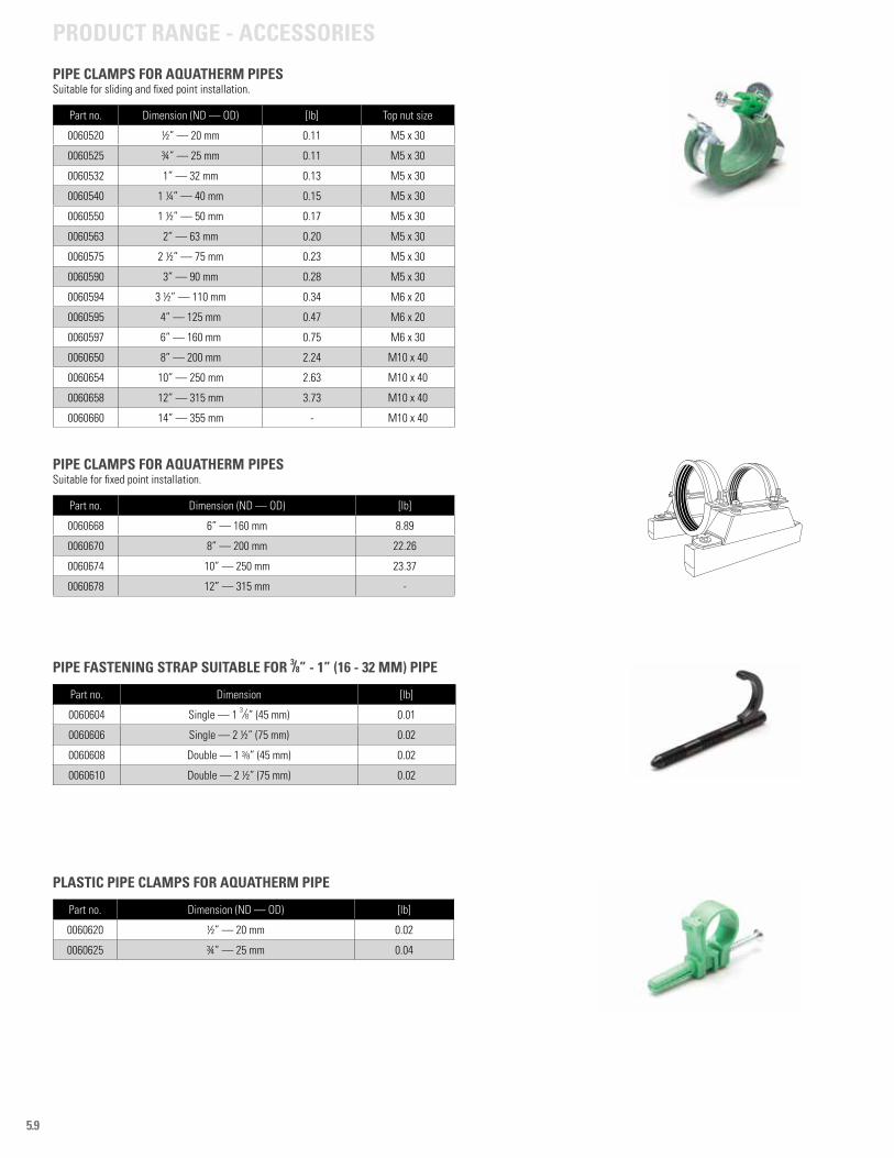
5.9
PIPE CLAMPS FOR AQUATHERM PIPESSuitable for sliding and fixed point installation.
Part no. Dimension (ND — OD) [lb] Top nut size
0060520 ½” — 20 mm 0.11 M5 x 30
0060525 ¾” — 25 mm 0.11 M5 x 30
0060532 1” — 32 mm 0.13 M5 x 30
0060540 1 ¼” — 40 mm 0.15 M5 x 30
0060550 1 ½” — 50 mm 0.17 M5 x 30
0060563 2” — 63 mm 0.20 M5 x 30
0060575 2 ½” — 75 mm 0.23 M5 x 30
0060590 3” — 90 mm 0.28 M5 x 30
0060594 3 ½” — 110 mm 0.34 M6 x 20
0060595 4” — 125 mm 0.47 M6 x 20
0060597 6” — 160 mm 0.75 M6 x 30
0060650 8” — 200 mm 2.24 M10 x 40
0060654 10” — 250 mm 2.63 M10 x 40
0060658 12” — 315 mm 3.73 M10 x 40
0060660 14” — 355 mm - M10 x 40
PIPE CLAMPS FOR AQUATHERM PIPESSuitable for fixed point installation.
Part no. Dimension (ND — OD) [lb]
0060668 6” — 160 mm 8.89
0060670 8” — 200 mm 22.26
0060674 10” — 250 mm 23.37
0060678 12” — 315 mm -
PIPE FASTENING STRAP SUITABLE FOR 3/8” - 1” (16 - 32 MM) PIPE
Part no. Dimension [lb]
0060604 Single — 1 3/8” (45 mm) 0.01
0060606 Single — 2 ½” (75 mm) 0.02
0060608 Double — 1 3/8” (45 mm) 0.02
0060610 Double — 2 ½” (75 mm) 0.02
PLASTIC PIPE CLAMPS FOR AQUATHERM PIPE
Part no. Dimension (ND — OD) [lb]
0060620 ½” — 20 mm 0.02
0060625 ¾” — 25 mm 0.04
PRODUCT RANGE - ACCESSORIES
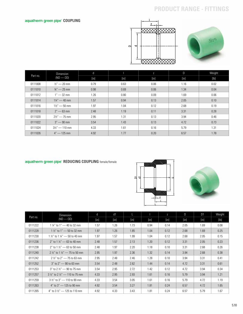
5.10
Part no. Dimension (ND — OD)
d l z D Weight
[in] [in] [in] [in] [lb]
0111008 ½” — 20 mm 0.79 0.63 0.06 1.16 0.02
0111010 ¾” — 25 mm 0.98 0.69 0.06 1.34 0.04
0111012 1” — 32 mm 1.26 0.80 0.09 1.69 0.06
0111014 1¼” — 40 mm 1.57 0.94 0.13 2.05 0.10
0111016 1½” — 50 mm 1.97 1.04 0.12 2.68 0.19
0111018 2” — 63 mm 2.48 1.19 0.11 3.31 0.28
0111020 2½” — 75 mm 2.95 1.31 0.13 3.94 0.46
0111022 3” — 90 mm 3.54 1.43 0.13 4.72 0.73
0111024 3½” — 110 mm 4.33 1.61 0.16 5.79 1.31
0111026 4” — 125 mm 4.92 1.77 0.20 6.57 1.78
Part no. Dimension (ND — OD)
d d1 L l z D D1 Weight
[in] [in] [in] [in] [in] [in] [in] [lb]
0111222 1 ¼” to 1” — 40 to 32 mm 1.57 1.26 1.73 0.94 0.14 2.05 1.69 0.08
0111228 1 ½” to 1” — 50 to 32 mm 1.97 1.26 1.85 1.04 0.12 2.68 1.69 0.25
0111230 1 ½” to 1 ¼” — 50 to 40 mm 1.97 1.57 1.99 1.04 0.12 2.68 2.05 0.15
0111236 2” to 1 ¼” — 63 to 40 mm 2.48 1.57 2.13 1.20 0.12 3.31 2.05 0.23
0111238 2” to 1 ½” — 63 to 50 mm 2.48 1.97 2.20 1.18 0.10 3.31 2.68 0.26
0111240 2 ½” to 1 ½” — 75 to 50 mm 2.95 1.97 2.36 1.32 0.14 3.94 2.68 0.38
0111242 2 ½” to 2” — 75 to 63 mm 2.95 2.48 2.46 1.28 0.10 3.94 3.31 0.41
0111252 3” to 2” — 90 to 63 mm 3.54 2.48 2.62 1.44 0.14 4.72 3.31 0.61
0111253 3” to 2 ½” — 90 to 75 mm 3.54 2.95 2.72 1.42 0.12 4.72 3.94 0.34
0111257 3 ½” to 2 ½” — 110 to 75 mm 4.33 2.95 2.93 1.61 0.16 5.79 3.94 1.21
0111259 3 ½” to 3” — 110 to 90 mm 4.33 3.54 3.05 1.61 0.16 5.79 4.72 1.19
0111263 4” to 3” — 125 to 90 mm 4.92 3.54 3.27 1.81 0.24 6.57 4.72 1.65
0111265 4” to 3 ½” — 125 to 110 mm 4.92 4.33 3.43 1.81 0.24 6.57 5.79 1.67
aquatherm green pipe® COUPLING
aquatherm green pipe® REDUCING COUPLING female/female
PRODUCT RANGE - FITTINGS
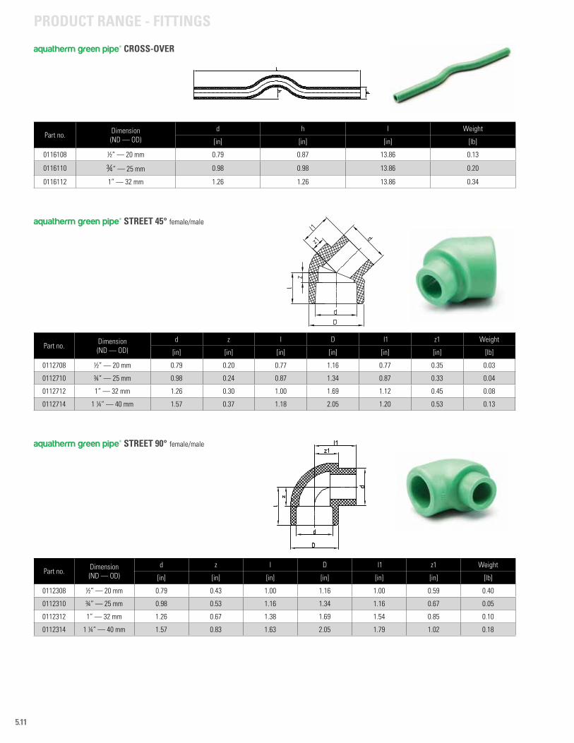
5.11
PRODUCT RANGE - FITTINGS
Part no. Dimension (ND — OD)
d z l D l1 z1 Weight
[in] [in] [in] [in] [in] [in] [lb]
0112308 ½” — 20 mm 0.79 0.43 1.00 1.16 1.00 0.59 0.40
0112310 ¾” — 25 mm 0.98 0.53 1.16 1.34 1.16 0.67 0.05
0112312 1” — 32 mm 1.26 0.67 1.38 1.69 1.54 0.85 0.10
0112314 1 ¼” — 40 mm 1.57 0.83 1.63 2.05 1.79 1.02 0.18
aquatherm green pipe® STREET 90° female/male
Part no. Dimension (ND — OD)
d z l D l1 z1 Weight
[in] [in] [in] [in] [in] [in] [lb]
0112708 ½” — 20 mm 0.79 0.20 0.77 1.16 0.77 0.35 0.03
0112710 ¾” — 25 mm 0.98 0.24 0.87 1.34 0.87 0.33 0.04
0112712 1” — 32 mm 1.26 0.30 1.00 1.69 1.12 0.45 0.08
0112714 1 ¼” — 40 mm 1.57 0.37 1.18 2.05 1.20 0.53 0.13
aquatherm green pipe® STREET 45° female/male
Part no. Dimension (ND — OD)
d h l Weight
[in] [in] [in] [lb]
0116108 ½” — 20 mm 0.79 0.87 13.86 0.13
0116110 ¾” — 25 mm 0.98 0.98 13.86 0.20
0116112 1” — 32 mm 1.26 1.26 13.86 0.34
aquatherm green pipe® CROSS-OVER
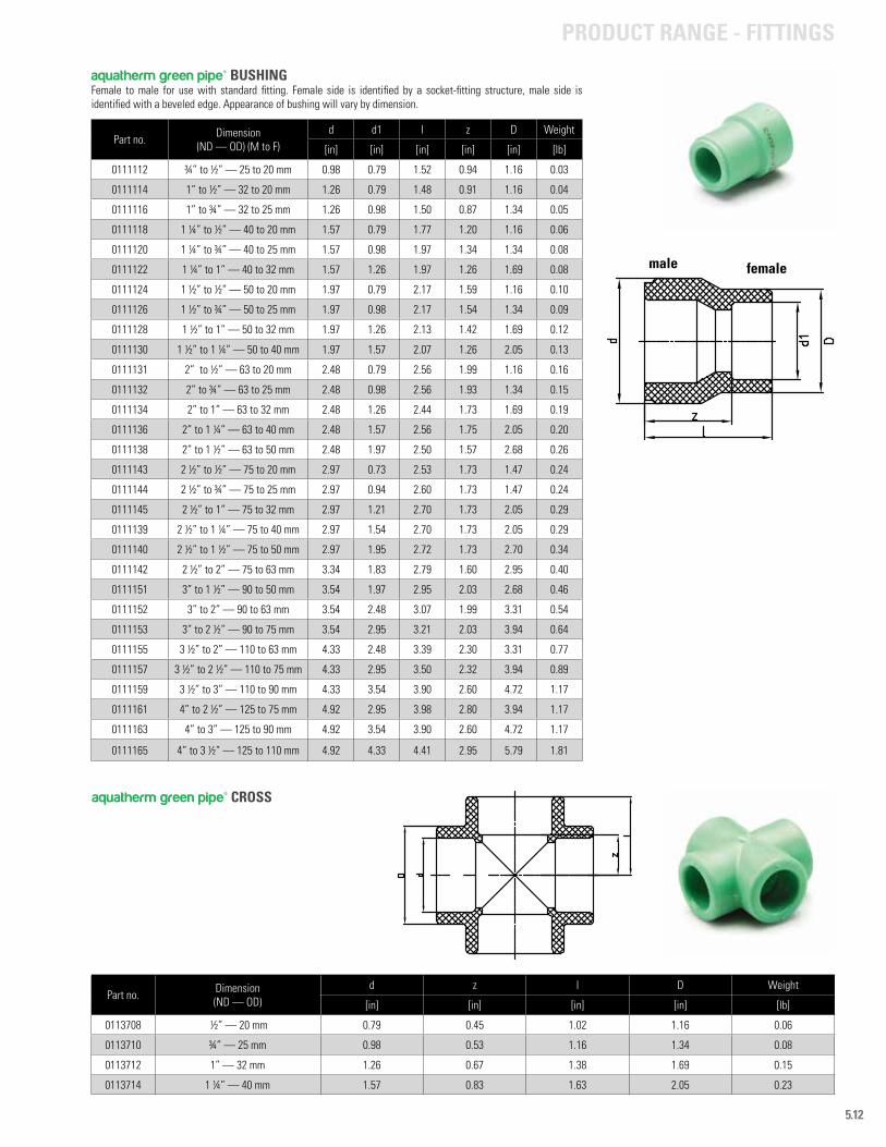
5.12
Part no. Dimension (ND — OD) (M to F)
d d1 l z D Weight
[in] [in] [in] [in] [in] [lb]
0111112 ¾” to ½” — 25 to 20 mm 0.98 0.79 1.52 0.94 1.16 0.03
0111114 1” to ½” — 32 to 20 mm 1.26 0.79 1.48 0.91 1.16 0.04
0111116 1” to ¾” — 32 to 25 mm 1.26 0.98 1.50 0.87 1.34 0.05
0111118 1 ¼” to ½” — 40 to 20 mm 1.57 0.79 1.77 1.20 1.16 0.06
0111120 1 ¼” to ¾” — 40 to 25 mm 1.57 0.98 1.97 1.34 1.34 0.08
0111122 1 ¼” to 1” — 40 to 32 mm 1.57 1.26 1.97 1.26 1.69 0.08
0111124 1 ½” to ½” — 50 to 20 mm 1.97 0.79 2.17 1.59 1.16 0.10
0111126 1 ½” to ¾” — 50 to 25 mm 1.97 0.98 2.17 1.54 1.34 0.09
0111128 1 ½” to 1” — 50 to 32 mm 1.97 1.26 2.13 1.42 1.69 0.12
0111130 1 ½” to 1 ¼” — 50 to 40 mm 1.97 1.57 2.07 1.26 2.05 0.13
0111131 2” to ½” — 63 to 20 mm 2.48 0.79 2.56 1.99 1.16 0.16
0111132 2” to ¾” — 63 to 25 mm 2.48 0.98 2.56 1.93 1.34 0.15
0111134 2” to 1” — 63 to 32 mm 2.48 1.26 2.44 1.73 1.69 0.19
0111136 2” to 1 ¼” — 63 to 40 mm 2.48 1.57 2.56 1.75 2.05 0.20
0111138 2” to 1 ½” — 63 to 50 mm 2.48 1.97 2.50 1.57 2.68 0.26
0111143 2 ½” to ½” — 75 to 20 mm 2.97 0.73 2.53 1.73 1.47 0.24
0111144 2 ½” to ¾” — 75 to 25 mm 2.97 0.94 2.60 1.73 1.47 0.24
0111145 2 ½” to 1” — 75 to 32 mm 2.97 1.21 2.70 1.73 2.05 0.29
0111139 2 ½” to 1 ¼” — 75 to 40 mm 2.97 1.54 2.70 1.73 2.05 0.29
0111140 2 ½” to 1 ½” — 75 to 50 mm 2.97 1.95 2.72 1.73 2.70 0.34
0111142 2 ½” to 2” — 75 to 63 mm 3.34 1.83 2.79 1.60 2.95 0.40
0111151 3” to 1 ½” — 90 to 50 mm 3.54 1.97 2.95 2.03 2.68 0.46
0111152 3” to 2” — 90 to 63 mm 3.54 2.48 3.07 1.99 3.31 0.54
0111153 3” to 2 ½” — 90 to 75 mm 3.54 2.95 3.21 2.03 3.94 0.64
0111155 3 ½” to 2” — 110 to 63 mm 4.33 2.48 3.39 2.30 3.31 0.77
0111157 3 ½” to 2 ½” — 110 to 75 mm 4.33 2.95 3.50 2.32 3.94 0.89
0111159 3 ½” to 3” — 110 to 90 mm 4.33 3.54 3.90 2.60 4.72 1.17
0111161 4” to 2 ½” — 125 to 75 mm 4.92 2.95 3.98 2.80 3.94 1.17
0111163 4” to 3” — 125 to 90 mm 4.92 3.54 3.90 2.60 4.72 1.17
0111165 4” to 3 ½” — 125 to 110 mm 4.92 4.33 4.41 2.95 5.79 1.81
femalemale
aquatherm green pipe® BUSHINGFemale to male for use with standard fitting. Female side is identified by a socket-fitting structure, male side is identified with a beveled edge. Appearance of bushing will vary by dimension.
PRODUCT RANGE - FITTINGS
Part no. Dimension (ND — OD)
d z l D Weight
[in] [in] [in] [in] [lb]
0113708 ½” — 20 mm 0.79 0.45 1.02 1.16 0.06
0113710 ¾” — 25 mm 0.98 0.53 1.16 1.34 0.08
0113712 1” — 32 mm 1.26 0.67 1.38 1.69 0.15
0113714 1 ¼” — 40 mm 1.57 0.83 1.63 2.05 0.23
aquatherm green pipe® CROSS
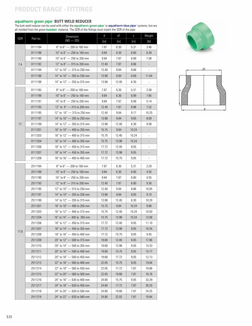
5.13
SDR Part no. Dimension (ND — OD)
d d1 z Weight
[in] [in] [in] [lb]
7.4
0111184 8” to 6” — 200 to 160 mm 7.87 6.30 5.31 3.46
0111188 10” to 6” — 250 to 160 mm 9.84 6.30 6.80 6.39
0111190 10” to 8” — 250 to 200 mm 9.84 7.87 6.89 7.08
0111192 12” to 8” — 315 to 200 mm 12.40 7.87 8.86 -
0111194 12” to 10” — 315 to 250 mm 12.40 9.84 8.86 -
0111196 14” to 10” — 355 to 250 mm 13.98 9.84 6.69 11.64
0111198 14” to 12” — 355 to 315 mm 13.98 12.40 6.30 -
11
0111185 8” to 6” — 200 to 160 mm 7.87 6.30 5.31 2.58
0111189 10” to 6” — 250 to 160 mm 9.84 6.30 6.89 7.65
0111191 10” to 8” — 250 to 200 mm 9.84 7.87 6.89 5.14
0111193 12” to 8” — 315 to 200 mm 12.40 7.87 8.86 7.52
0111195 12” to 10” — 315 to 250 mm 12.40 9.84 9.17 10.25
0111197 14” to 10” — 355 to 250 mm 13.98 9.84 9.65 8.69
0111199 14” to 12” — 355 to 315 mm 13.98 12.40 6.30 9.58
0111201 16” to 10” — 400 to 250 mm 15.75 9.84 10.24 -
0111203 16” to 12” — 400 to 315 mm 15.75 12.40 10.24 -
0111204 16” to 14” — 400 to 355 mm 15.75 13.98 10.24 -
0111206 18” to 12” — 450 to 315 mm 17.72 12.40 9.05 -
0111207 18” to 14” — 450 to 355 mm 17.72 13.98 9.05 -
0111208 18” to 16” — 450 to 400 mm 17.72 15.75 9.05 -
17.6
2511184 8” to 6” — 200 to 160 mm 7.87 6.30 5.31 2.29
2511188 10” to 6” — 250 to 160 mm 9.84 6.30 6.80 4.55
2511190 10” to 8” — 250 to 200 mm 9.84 7.87 6.80 4.55
2511193 12” to 8” — 315 to 200 mm 12.40 7.87 6.80 9.30
2511195 12” to 10” — 315 to 250 mm 12.40 9.84 8.86 10.05
2511197 14” to 10” — 355 to 250 mm 13.98 9.84 9.65 9.10
2511199 14” to 12” — 355 to 315 mm 13.98 12.40 6.30 10.20
2511201 16” to 10” — 400 to 250 mm 15.75 9.84 10.24 9.88
2511203 16” to 12” — 400 to 315 mm 15.75 12.40 10.24 10.50
2511204 16” to 14” — 400 to 355 mm 15.75 13.98 10.24 12.68
2511206 18” to 12” — 450 to 315 mm 17.72 12.40 9.05 11.10
2511207 18” to 14” — 450 to 355 mm 17.72 13.98 9.05 10.34
2511208 18” to 16” — 450 to 400 mm 17.72 15.75 9.05 9.45
2511209 20” to 12” — 500 to 315 mm 19.68 12.40 9.05 17.86
2511210 20” to 14” — 500 to 355 mm 19.68 13.98 9.05 14.33
2511211 20” to 16” — 500 to 400 mm 19.68 15.75 9.05 14.77
2511212 20” to 18” — 500 to 450 mm 19.68 17.72 9.05 12.13
2511213 22” to 16” — 560 to 400 mm 22.05 15.75 9.05 19.84
2511214 22” to 18” — 560 to 450 mm 22.05 17.72 7.87 19.96
2511215 22” to 20” — 560 to 500 mm 22.05 19.68 7.87 16.76
2511216 24” to 16” — 630 to 400 mm 24.80 15.75 9.05 33.29
2511217 24” to 18” — 630 to 450 mm 24.80 17.72 7.87 30.20
2511218 24” to 20” — 630 to 500 mm 24.80 19.68 7.87 24.25
2511219 24” to 22” — 630 to 560 mm 24.80 22.02 7.87 19.84
aquatherm green pipe® BUTT WELD REDUCERThe butt weld reducer can be used with either the aquatherm green pipe® or aquatherm blue pipe® systems, but are all molded from the green fusiolen® material. The SDR of the fittings must match the SDR of the pipe.
PRODUCT RANGE - FITTINGS
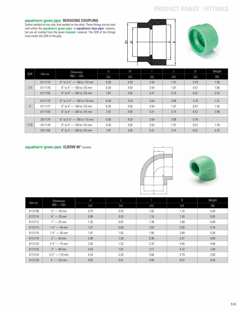
5.14
SDR Part no. Dimension (ND — OD)
d d1 l z D Weight
[in] [in] [in] [in] [in] [lb]
7.4
0111174 6” to 3 ½” — 160 to 110 mm 6.30 4.33 3.43 1.97 5.79 1.59
0111176 6” to 4” — 160 to 125 mm 6.30 4.92 3.54 1.97 6.57 1.80
0111182 8” to 4” — 200 to 125 mm 7.87 4.92 5.31 3.74 6.57 3.53
11
0111175 6” to 3 ½” — 160 to 110 mm 6.30 4.33 3.54 2.09 5.79 1.31
0111177 6” to 4” — 160 to 125 mm 6.30 4.92 3.54 1.97 6.57 1.55
0111183 8” to 4” — 200 to 125 mm 7.87 4.92 5.31 3.74 6.57 2.99
17.6
2511174 6” to 3 ½” — 160 to 110 mm 6.30 4.33 3.54 2.09 5.79 -
2511176 6” to 4” — 160 to 125 mm 6.30 4.92 3.54 1.97 6.57 1.39
2511182 8” to 4” — 200 to 125 mm 7.87 4.92 5.31 3.74 6.57 2.33
Part no. Dimension (ND — OD)
d z l D Weight
[in] [in] [in] [in] [lb]
0112108 ½” — 20 mm 0.79 0.43 1.00 1.16 0.04
0112110 ¾” — 25 mm 0.98 0.53 1.16 1.34 0.05
0112112 1” — 32 mm 1.26 0.67 1.38 1.69 0.09
0112114 1 ¼” — 40 mm 1.57 0.83 1.63 2.05 0.16
0112116 1 ½” — 50 mm 1.97 1.02 1.95 2.68 0.36
0112118 2” — 63 mm 2.48 1.28 2.36 3.31 0.64
0112120 2 ½” — 75 mm 2.95 1.52 2.70 3.94 0.98
0112122 3” — 90 mm 3.54 1.81 3.11 4.72 1.64
0112124 3 ½” — 110 mm 4.33 2.20 3.66 5.79 2.83
0112126 4” — 125 mm 4.92 3.01 4.59 6.57 4.42
aquatherm green pipe® REDUCING COUPLING Socket welded on one side, butt welded on the other. These fittings can be used with either the aquatherm green pipe® or aquatherm blue pipe® systems, but are all molded from the green fusiolen® material. The SDR of the fittings must match the SDR of the pipe.
aquatherm green pipe® ELBOW 90° (socket)
PRODUCT RANGE - FITTINGS
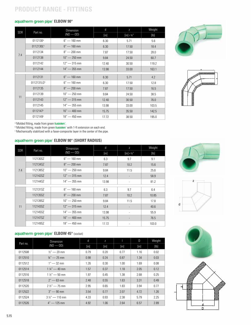
5.15
SDR Part no. Dimension (ND — OD)
d z Weight
[in] [in] ± 1/8” [lb]
7.4
0112130a 6” — 160 mm 6.30 5.71 5.6
0112130Lb 6” — 160 mm 6.30 17.50 18.4
0112134 8” — 200 mm 7.87 17.50 28.0
0112138 10” — 250 mm 9.84 24.50 60.7
0112142 12” — 315 mm 12.40 30.50 119.2
0112144 14” — 355 mm 13.98 33.00 163.1
11
0112131 6” — 160 mm 6.30 5.71 4.2
0112131LGb 6” — 160 mm 6.30 17.50 12.8
0112135 8” — 200 mm 7.87 17.50 16.5
0112139 10” — 250 mm 9.84 24.50 38.5
0112143 12” — 315 mm 12.40 30.50 76.0
0112145 14” — 355 mm 13.98 33.00 103.5
0112147c 16” — 400 mm 15.75 35.50 142.5
0112149c 18” — 450 mm 17.72 38.50 195.0
SDR Part no. Dimension (ND — OD)
d z Weight
[in] [in] ± 1/8” [lb]
7.4
112130SZ 6” — 160 mm 6.3 9.7 9.1
112134SZ 8” — 200 mm 7.87 10.2 15.6
112138SZ 10” — 250 mm 9.84 11.5 25.6
112142SZ 12” — 315 mm 12.4 - 58.9
112144SZ 14” — 355 mm 13.98 - 81.2
11
112131SZ 6” — 160 mm 6.3 9.7 6.4
112135SZ 8” — 200 mm 7.87 10.2 10.85
112139SZ 10” — 250 mm 9.84 11.5 17.8
112143SZ 12” — 315 mm 12.4 - 40.6
112145SZ 14” — 355 mm 13.98 - 55.9
112147SZ 16” — 400 mm 15.75 - 76.5
112149SZ 18” — 450 mm 17.72 - 103.0
aquatherm green pipe® ELBOW 90°
aquatherm green pipe® ELBOW 90° (SHORT RADIUS)
a Molded fitting, made from green fusiolen®.b Molded fitting, made from green fusiolen® with 1-ft extension on each end.c Mechanically stabilized with a faser-composite layer in the center of the pipe.
PRODUCT RANGE - FITTINGS
Part no. Dimension (ND — OD)
d z l D Weight
[in] [in] [in] [in] [lb]
0112508 ½” — 20 mm 0.79 0.20 0.77 1.16 0.02
0112510 ¾” — 25 mm 0.98 0.24 0.87 1.34 0.03
0112512 1” — 32 mm 1.26 0.30 1.00 1.69 0.08
0112514 1 ¼” — 40 mm 1.57 0.37 1.18 2.05 0.12
0112516 1 ½” — 50 mm 1.97 0.45 1.38 2.68 0.25
0112518 2” — 63 mm 2.48 0.55 1.63 3.31 0.49
0112520 2 ½” — 75 mm 2.95 0.65 1.83 3.94 0.77
0112522 3” — 90 mm 3.54 0.77 2.07 4.72 1.26
0112524 3 ½” — 110 mm 4.33 0.93 2.38 5.79 2.25
0112526 4” — 125 mm 4.92 1.06 2.64 6.57 2.89
aquatherm green pipe® ELBOW 45° (socket)
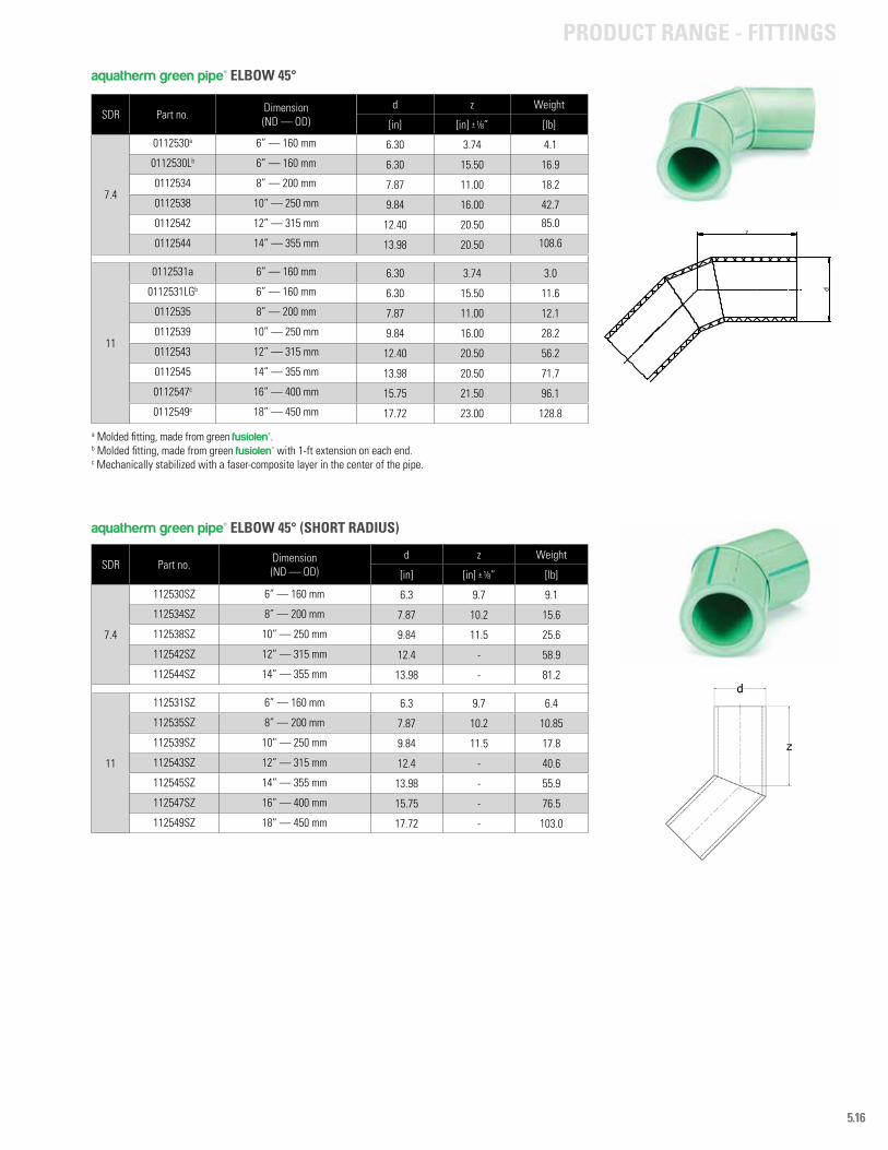
5.16
SDR Part no. Dimension(ND — OD)
d z Weight
[in] [in] ± 1/8” [lb]
7.4
0112530a 6” — 160 mm 6.30 3.74 4.1
0112530Lb 6” — 160 mm 6.30 15.50 16.9
0112534 8” — 200 mm 7.87 11.00 18.2
0112538 10” — 250 mm 9.84 16.00 42.7
0112542 12” — 315 mm 12.40 20.50 85.0
0112544 14” — 355 mm 13.98 20.50 108.6
11
0112531a 6” — 160 mm 6.30 3.74 3.0
0112531LGb 6” — 160 mm 6.30 15.50 11.6
0112535 8” — 200 mm 7.87 11.00 12.1
0112539 10” — 250 mm 9.84 16.00 28.2
0112543 12” — 315 mm 12.40 20.50 56.2
0112545 14” — 355 mm 13.98 20.50 71.7
0112547c 16” — 400 mm 15.75 21.50 96.1
0112549c 18” — 450 mm 17.72 23.00 128.8
z
d
a Molded fitting, made from green fusiolen®.b Molded fitting, made from green fusiolen® with 1-ft extension on each end.c Mechanically stabilized with a faser-composite layer in the center of the pipe.
aquatherm green pipe® ELBOW 45°
SDR Part no. Dimension (ND — OD)
d z Weight
[in] [in] ± 1/8” [lb]
7.4
112530SZ 6” — 160 mm 6.3 9.7 9.1
112534SZ 8” — 200 mm 7.87 10.2 15.6
112538SZ 10” — 250 mm 9.84 11.5 25.6
112542SZ 12” — 315 mm 12.4 - 58.9
112544SZ 14” — 355 mm 13.98 - 81.2
11
112531SZ 6” — 160 mm 6.3 9.7 6.4
112535SZ 8” — 200 mm 7.87 10.2 10.85
112539SZ 10” — 250 mm 9.84 11.5 17.8
112543SZ 12” — 315 mm 12.4 - 40.6
112545SZ 14” — 355 mm 13.98 - 55.9
112547SZ 16” — 400 mm 15.75 - 76.5
112549SZ 18” — 450 mm 17.72 - 103.0
aquatherm green pipe® ELBOW 45° (SHORT RADIUS)
PRODUCT RANGE - FITTINGS
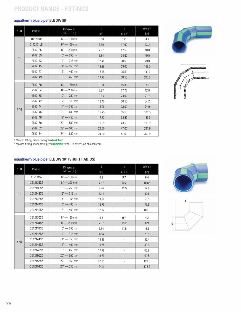
5.17
PRODUCT RANGE - FITTINGS
SDR Part no. Dimension (ND — OD)
d z Weight
[in] [in] ± 1/8” [lb]
11
112131SZ 6” — 160 mm 6.3 9.7 6.4
2612135SZ 8” — 200 mm 7.87 10.2 10.85
2612139SZ 10” — 250 mm 9.84 11.5 17.8
2012143SZ 12” — 315 mm 12.4 - 40.6
2012145SZ 14” — 355 mm 13.98 - 55.9
2012147SZ 16” — 400 mm 15.75 - 76.5
2012149SZ 18” — 450 mm 17.72 - 103.0
17.6
2512130SZ 6” — 160 mm 6.3 9.7 4.2
2512134SZ 8” — 200 mm 7.87 10.2 6.9
2512138SZ 10” — 250 mm 9.84 11.5 11.6
2512142SZ 12” — 315 mm 12.4 - 26.5
2512144SZ 14” — 355 mm 13.98 - 36.4
2512146SZ 16” — 400 mm 15.75 - 49.8
2512148SZ 18” — 450 mm 17.72 - 66.9
2512150SZ 20” — 500 mm 19.69 - 90.5
2512152SZ 22” — 560 mm 22.05 - 123.6
2512154SZ 24” — 630 mm 24.8 - 178.9
aquatherm blue pipe® ELBOW 90° (SHORT RADIUS)
SDR Part no. Dimension (ND — OD)
d z Weight
[in] [in] ± 1/8” [lb]
11
0112131a 6” — 160 mm 6.30 5.71 4.2
0112131LBb 6” — 160 mm 6.30 17.50 13.2
2612135 8” — 200 mm 7.87 17.50 18.0
2612139 10” — 250 mm 9.84 24.50 40.5
2012143 12“ — 315 mm 12.40 30.50 79.0
2012145 14“ — 355 mm 13.98 33.00 108.0
2012147 16“ — 400 mm 15.75 35.50 149.0
2012149 18“ — 450 mm 17.72 38.50 203.0
17.6
2512130 6” — 160 mm 6.30 15.35 7.0
2512134 8” — 200 mm 7.87 17.72 12.8
2512138 10” — 250 mm 9.84 24.61 27.7
2512142 12” — 315 mm 12.40 30.50 54.2
2512144 14” — 355 mm 13.98 33.00 74.0
2512146 16” — 400 mm 15.75 35.50 101.5
2512148 18” — 450 mm 17.72 38.50 139.0
2512150 20” — 500 mm 19.69 43.50 193.9
2512152 22” — 560 mm 22.05 47.00 261.9
2512154 24” — 630 mm 24.80 51.00 360.9
a Molded fitting, made from green fusiolen®.b Molded fitting, made from green fusiolen® with 1-ft extension on each end.
aquatherm blue pipe® ELBOW 90°
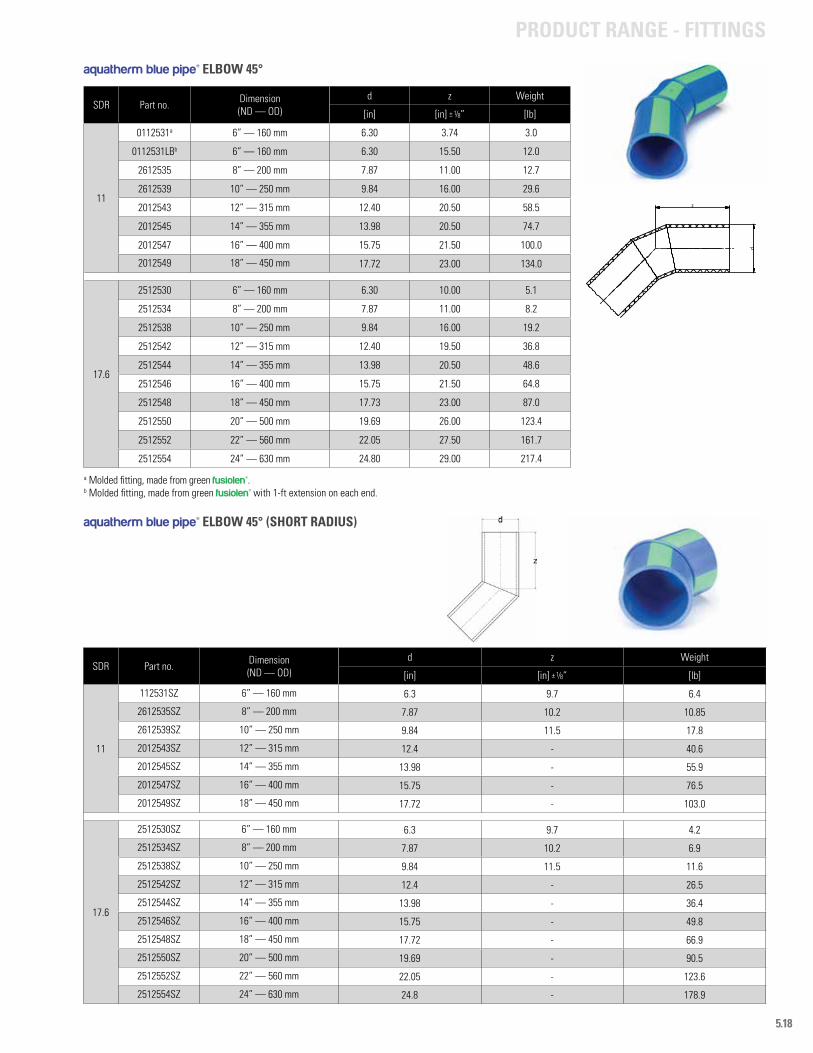
5.18
SDR Part no. Dimension (ND — OD)
d z Weight
[in] [in] ± 1/8” [lb]
11
0112531a 6” — 160 mm 6.30 3.74 3.0
0112531LBb 6” — 160 mm 6.30 15.50 12.0
2612535 8” — 200 mm 7.87 11.00 12.7
2612539 10” — 250 mm 9.84 16.00 29.6
2012543 12” — 315 mm 12.40 20.50 58.5
2012545 14” — 355 mm 13.98 20.50 74.7
2012547 16” — 400 mm 15.75 21.50 100.0
2012549 18” — 450 mm 17.72 23.00 134.0
17.6
2512530 6” — 160 mm 6.30 10.00 5.1
2512534 8” — 200 mm 7.87 11.00 8.2
2512538 10” — 250 mm 9.84 16.00 19.2
2512542 12” — 315 mm 12.40 19.50 36.8
2512544 14” — 355 mm 13.98 20.50 48.6
2512546 16” — 400 mm 15.75 21.50 64.8
2512548 18” — 450 mm 17.73 23.00 87.0
2512550 20” — 500 mm 19.69 26.00 123.4
2512552 22” — 560 mm 22.05 27.50 161.7
2512554 24” — 630 mm 24.80 29.00 217.4
z
d
aquatherm blue pipe® ELBOW 45°
a Molded fitting, made from green fusiolen®.b Molded fitting, made from green fusiolen® with 1-ft extension on each end.
SDR Part no. Dimension (ND — OD)
d z Weight
[in] [in] ± 1/8” [lb]
11
112531SZ 6” — 160 mm 6.3 9.7 6.4
2612535SZ 8” — 200 mm 7.87 10.2 10.85
2612539SZ 10” — 250 mm 9.84 11.5 17.8
2012543SZ 12” — 315 mm 12.4 - 40.6
2012545SZ 14” — 355 mm 13.98 - 55.9
2012547SZ 16” — 400 mm 15.75 - 76.5
2012549SZ 18” — 450 mm 17.72 - 103.0
17.6
2512530SZ 6” — 160 mm 6.3 9.7 4.2
2512534SZ 8” — 200 mm 7.87 10.2 6.9
2512538SZ 10” — 250 mm 9.84 11.5 11.6
2512542SZ 12” — 315 mm 12.4 - 26.5
2512544SZ 14” — 355 mm 13.98 - 36.4
2512546SZ 16” — 400 mm 15.75 - 49.8
2512548SZ 18” — 450 mm 17.72 - 66.9
2512550SZ 20” — 500 mm 19.69 - 90.5
2512552SZ 22” — 560 mm 22.05 - 123.6
2512554SZ 24” — 630 mm 24.8 - 178.9
aquatherm blue pipe® ELBOW 45° (SHORT RADIUS)
PRODUCT RANGE - FITTINGS
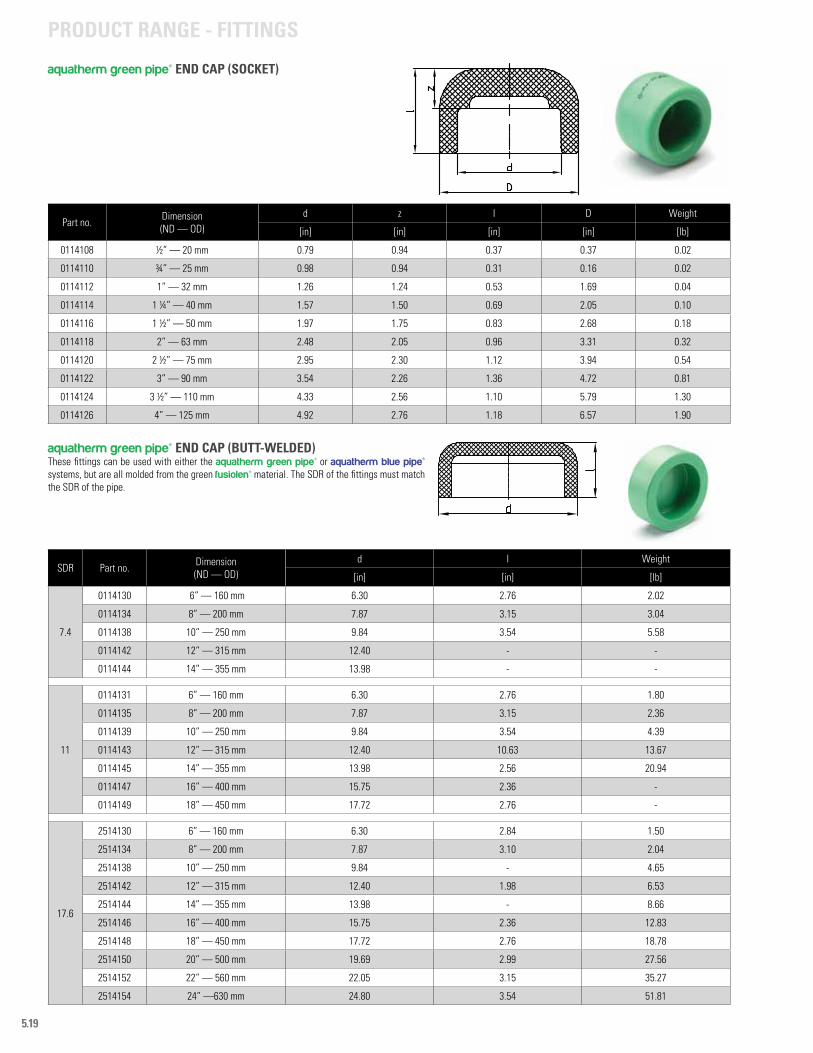
5.19
Part no. Dimension (ND — OD)
d z l D Weight
[in] [in] [in] [in] [lb]
0114108 ½” — 20 mm 0.79 0.94 0.37 0.37 0.02
0114110 ¾” — 25 mm 0.98 0.94 0.31 0.16 0.02
0114112 1” — 32 mm 1.26 1.24 0.53 1.69 0.04
0114114 1 ¼” — 40 mm 1.57 1.50 0.69 2.05 0.10
0114116 1 ½” — 50 mm 1.97 1.75 0.83 2.68 0.18
0114118 2” — 63 mm 2.48 2.05 0.96 3.31 0.32
0114120 2 ½” — 75 mm 2.95 2.30 1.12 3.94 0.54
0114122 3” — 90 mm 3.54 2.26 1.36 4.72 0.81
0114124 3 ½” — 110 mm 4.33 2.56 1.10 5.79 1.30
0114126 4” — 125 mm 4.92 2.76 1.18 6.57 1.90
aquatherm green pipe® END CAP (SOCKET)
SDR Part no. Dimension (ND — OD)
d l Weight
[in] [in] [lb]
7.4
0114130 6” — 160 mm 6.30 2.76 2.02
0114134 8” — 200 mm 7.87 3.15 3.04
0114138 10” — 250 mm 9.84 3.54 5.58
0114142 12” — 315 mm 12.40 - -
0114144 14” — 355 mm 13.98 - -
11
0114131 6” — 160 mm 6.30 2.76 1.80
0114135 8” — 200 mm 7.87 3.15 2.36
0114139 10” — 250 mm 9.84 3.54 4.39
0114143 12” — 315 mm 12.40 10.63 13.67
0114145 14” — 355 mm 13.98 2.56 20.94
0114147 16” — 400 mm 15.75 2.36 -
0114149 18” — 450 mm 17.72 2.76 -
17.6
2514130 6” — 160 mm 6.30 2.84 1.50
2514134 8” — 200 mm 7.87 3.10 2.04
2514138 10” — 250 mm 9.84 - 4.65
2514142 12” — 315 mm 12.40 1.98 6.53
2514144 14” — 355 mm 13.98 - 8.66
2514146 16” — 400 mm 15.75 2.36 12.83
2514148 18” — 450 mm 17.72 2.76 18.78
2514150 20” — 500 mm 19.69 2.99 27.56
2514152 22” — 560 mm 22.05 3.15 35.27
2514154 24” —630 mm 24.80 3.54 51.81
aquatherm green pipe® END CAP (BUTT-WELDED)These fittings can be used with either the aquatherm green pipe® or aquatherm blue pipe® systems, but are all molded from the green fusiolen® material. The SDR of the fittings must match the SDR of the pipe.
PRODUCT RANGE - FITTINGS
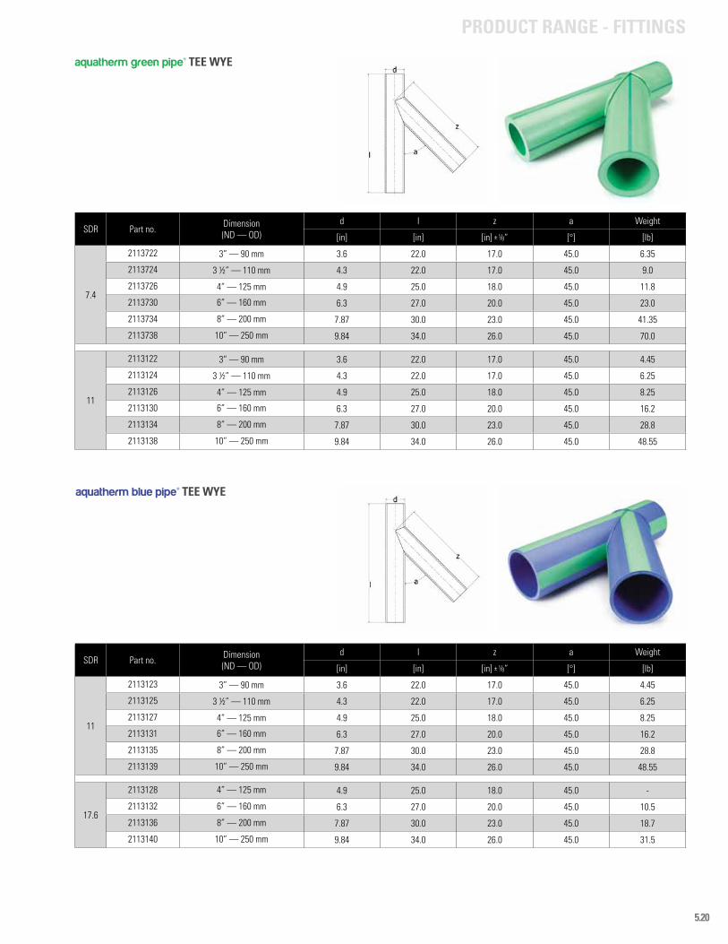
5.20
SDR Part no. Dimension (ND — OD)
d l z a Weight
[in] [in] [in] ± 1/8” [°] [lb]
11
2113123 3” — 90 mm 3.6 22.0 17.0 45.0 4.45
2113125 3 ½” — 110 mm 4.3 22.0 17.0 45.0 6.25
2113127 4” — 125 mm 4.9 25.0 18.0 45.0 8.25
2113131 6” — 160 mm 6.3 27.0 20.0 45.0 16.2
2113135 8” — 200 mm 7.87 30.0 23.0 45.0 28.8
2113139 10” — 250 mm 9.84 34.0 26.0 45.0 48.55
17.6
2113128 4” — 125 mm 4.9 25.0 18.0 45.0 -
2113132 6” — 160 mm 6.3 27.0 20.0 45.0 10.5
2113136 8” — 200 mm 7.87 30.0 23.0 45.0 18.7
2113140 10” — 250 mm 9.84 34.0 26.0 45.0 31.5
aquatherm blue pipe® TEE WYE
SDR Part no. Dimension (ND — OD)
d l z a Weight
[in] [in] [in] ± 1/8” [°] [lb]
7.4
2113722 3” — 90 mm 3.6 22.0 17.0 45.0 6.35
2113724 3 ½” — 110 mm 4.3 22.0 17.0 45.0 9.0
2113726 4” — 125 mm 4.9 25.0 18.0 45.0 11.8
2113730 6” — 160 mm 6.3 27.0 20.0 45.0 23.0
2113734 8” — 200 mm 7.87 30.0 23.0 45.0 41.35
2113738 10” — 250 mm 9.84 34.0 26.0 45.0 70.0
11
2113122 3” — 90 mm 3.6 22.0 17.0 45.0 4.45
2113124 3 ½” — 110 mm 4.3 22.0 17.0 45.0 6.25
2113126 4” — 125 mm 4.9 25.0 18.0 45.0 8.25
2113130 6” — 160 mm 6.3 27.0 20.0 45.0 16.2
2113134 8” — 200 mm 7.87 30.0 23.0 45.0 28.8
2113138 10” — 250 mm 9.84 34.0 26.0 45.0 48.55
aquatherm green pipe® TEE WYE
PRODUCT RANGE - FITTINGS
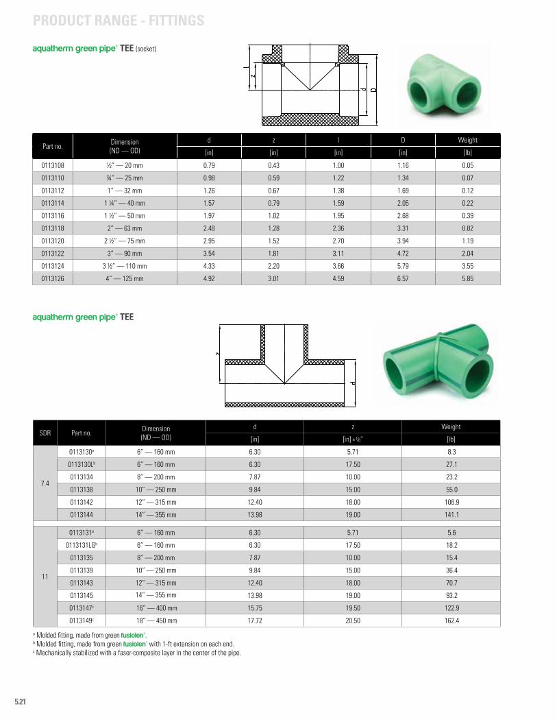
5.21
SDR Part no. Dimension (ND — OD)
d z Weight
[in] [in] ± 1/8” [lb]
7.4
0113130a 6” — 160 mm 6.30 5.71 8.3
0113130Lb 6” — 160 mm 6.30 17.50 27.1
0113134 8” — 200 mm 7.87 10.00 23.2
0113138 10” — 250 mm 9.84 15.00 55.0
0113142 12” — 315 mm 12.40 18.00 106.9
0113144 14” — 355 mm 13.98 19.00 141.1
11
0113131a 6” — 160 mm 6.30 5.71 5.6
0113131LGb 6” — 160 mm 6.30 17.50 18.2
0113135 8” — 200 mm 7.87 10.00 15.4
0113139 10” — 250 mm 9.84 15.00 36.4
0113143 12” — 315 mm 12.40 18.00 70.7
0113145 14” — 355 mm 13.98 19.00 93.2
0113147c 16” — 400 mm 15.75 19.50 122.9
0113149c 18” — 450 mm 17.72 20.50 162.4
aquatherm green pipe® TEE
a Molded fitting, made from green fusiolen®.b Molded fitting, made from green fusiolen® with 1-ft extension on each end.c Mechanically stabilized with a faser-composite layer in the center of the pipe.
PRODUCT RANGE - FITTINGS
Part no. Dimension (ND — OD)
d z l D Weight
[in] [in] [in] [in] [lb]
0113108 ½” — 20 mm 0.79 0.43 1.00 1.16 0.05
0113110 ¾” — 25 mm 0.98 0.59 1.22 1.34 0.07
0113112 1” — 32 mm 1.26 0.67 1.38 1.69 0.12
0113114 1 ¼” — 40 mm 1.57 0.79 1.59 2.05 0.22
0113116 1 ½” — 50 mm 1.97 1.02 1.95 2.68 0.39
0113118 2” — 63 mm 2.48 1.28 2.36 3.31 0.82
0113120 2 ½” — 75 mm 2.95 1.52 2.70 3.94 1.19
0113122 3” — 90 mm 3.54 1.81 3.11 4.72 2.04
0113124 3 ½” — 110 mm 4.33 2.20 3.66 5.79 3.55
0113126 4” — 125 mm 4.92 3.01 4.59 6.57 5.85
aquatherm green pipe® TEE (socket)
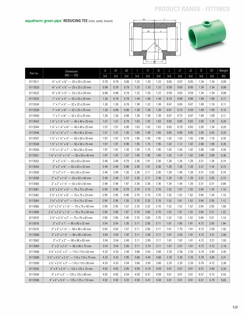
5.22
PRODUCT RANGE - FITTINGS
Part no. Dimension (ND — OD)
d d1 d2 l l1 l2 z z1 z2 D D1 Weight
[in] [in] [in] [in] [in] [in] [in] [in] [in] [in] [in] [lb]
0113511 ½” x ½” x ¾” — 20 x 20 x 25 mm 0.79 0.79 0.98 1.22 1.20 1.22 0.65 0.57 0.65 1.34 1.34 0.09
0113520 ¾” x ½” x ½” — 25 x 20 x 20 mm 0.98 0.79 0.79 1.22 1.20 1.22 0.59 0.63 0.65 1.34 1.34 0.08
0113522 ¾” x ¾” x ½” — 25 x 25 x 20 mm 0.98 0.98 0.79 1.22 1.20 1.22 0.59 0.63 0.59 1.34 1.34 0.08
0113532 1” x ½” x ½” — 32 x 20 x 20 mm 1.26 0.79 0.79 1.44 1.46 1.44 0.74 0.89 0.88 1.69 1.69 0.17
0113534 1” x 1” x ½” — 32 x 32 x 20 mm 1.26 1.26 0.79 1.38 1.22 1.38 0.67 0.65 0.67 1.69 1.16 0.11
0113538 1” x ¾” x ¾” — 32 x 25 x 25 mm 1.26 0.98 0.98 1.38 1.36 1.38 0.67 0.73 0.59 1.69 1.69 0.15
0113540 1” x 1” x ¾” — 32 x 32 x 25 mm 1.26 1.26 0.98 1.38 1.36 1.38 0.67 0.73 0.67 1.69 1.69 0.11
0113542 1 ¼” x 1 ¼” x ½” — 40 x 40 x 20 mm 1.57 1.57 0.79 1.63 1.42 1.63 0.83 0.85 0.83 2.05 1.34 0.20
0113544 1 ¼” x 1 ¼” x ¾” — 40 x 40 x 25 mm 1.57 1.57 0.98 1.63 1.42 1.63 0.83 0.79 0.83 2.05 1.34 0.20
0113546 1 ¼” x 1 ¼” x 1” — 40 x 40 x 32 mm 1.57 1.57 1.26 1.65 1.59 1.65 0.85 0.89 0.85 2.05 2.05 0.20
0113547 1 ½” x 1 ½” x ½” — 50 x 50 x 20 mm 1.97 1.97 0.79 1.95 1.59 1.95 1.02 1.02 1.02 2.68 1.16 0.35
0113548 1 ½” x 1 ½” x ¾” — 50 x 50 x 25 mm 1.97 1.97 0.98 1.95 1.75 1.95 1.02 1.12 1.02 2.68 1.69 0.35
0113550 1 ½” x 1 ½” x 1” — 50 x 50 x 32 mm 1.97 1.97 1.26 1.95 1.75 1.95 1.02 1.04 1.02 2.68 1.69 0.35
0113551 1 ½” x 1 ½” x 1 ¼” — 50 x 50 x 40 mm 1.97 1.97 1.57 1.95 1.95 1.95 1.02 1.14 1.02 2.68 2.68 0.36
0113552 2” x 2” x ½” — 63 x 63 x 20 mm 2.48 2.48 0.79 2.36 1.91 2.36 1.28 1.34 1.28 3.31 1.34 0.74
0113554 2” x 2” x ¾” — 63 x 63 x 25 mm 2.48 2.48 0.98 2.36 1.91 2.36 1.28 1.28 1.28 3.31 1.34 0.73
0113556 2” x 2” x 1” — 63 x 63 x 32 mm 2.48 2.48 1.26 2.36 2.11 2.36 1.28 1.40 1.28 3.31 2.05 0.75
0113558 2” x 2” x 1 ¼” — 63 x 63 x 40 mm 2.48 2.48 1.57 2.36 2.11 2.36 1.28 1.30 1.28 3.31 2.05 0.73
0113560 2” x 2” x 1 ½” — 63 x 63 x 50 mm 2.48 2.48 1.97 2.36 2.36 2.36 1.28 1.44 1.28 3.31 3.31 0.89
0113561 2 ½” x 2 ½” x ½” — 75 x 75 x 20 mm 2.95 2.95 0.79 2.70 2.15 2.70 1.52 1.57 1.52 3.94 1.34 1.10
0113562 2 ½” x 2 ½” x ¾” — 75 x 75 x 25 mm 2.95 2.95 0.98 2.70 2.15 2.70 1.52 1.52 1.52 3.94 1.34 1.10
0113564 2 ½” x 2 ½” x 1” — 75 x 75 x 32 mm 2.95 2.95 1.26 2.70 2.32 2.70 1.52 1.61 1.52 3.94 2.05 1.12
0113566 2 ½” x 2 ½” x 1 ¼” — 75 x 75 x 40 mm 2.95 2.95 1.57 2.70 2.32 2.70 1.52 1.52 1.52 3.94 2.05 1.09
0113568 2 ½” x 2 ½” x 1 ½” — 75 x 75 x 50 mm 2.95 2.95 1.97 2.70 2.60 2.70 1.52 1.67 1.52 3.94 3.31 1.22
0113570 2 ½” x 2 ½” x 2” — 75 x 75 x 63 mm 2.95 2.95 2.48 2.70 2.60 2.70 1.52 1.52 1.52 3.94 3.31 1.14
0113576 3” x 3” x 1” — 90 x 90 x 32 mm 3.54 3.54 1.26 3.11 2.56 3.11 1.81 1.85 1.81 4.72 2.05 1.94
0113578 3” x 3” x 1 ¼” — 90 x 90 x 40 mm 3.54 3.54 1.57 3.11 2.56 3.11 1.81 1.75 1.81 4.72 2.05 1.92
0113580 3” x 3” x 1 ½” — 90 x 90 x 50 mm 3.54 3.54 1.97 3.11 2.95 3.11 1.81 2.03 1.81 4.72 3.31 2.00
0113582 3” x 3” x 2” — 90 x 90 x 63 mm 3.54 3.54 2.48 3.11 2.95 3.11 1.81 1.87 1.81 4.72 3.31 1.93
0113584 3’’ x 3” x 2 ½” — 90 x 90 x 75 mm 3.54 3.54 2.95 3.11 3.19 3.11 1.81 2.01 1.81 4.72 4.72 2.19
0113586 3 ½” x 3 ½” x 2” — 110 x 110 x 63 mm 4.33 4.33 2.48 3.66 3.44 3.66 2.20 2.36 2.20 5.79 3.94 3.45
0113588 3 ½” x 3 ½” x 2 ½” — 110 x 110 x 75 mm 4.33 4.33 2.95 3.66 3.44 3.66 2.20 2.26 2.20 5.79 3.94 3.31
0113590 3 ½” x 3 ½” x 3” — 110 x 110 x 90 mm 4.33 4.33 3.54 3.66 3.50 3.66 2.20 2.20 2.20 5.79 4.72 3.38
0113592 4” x 4” x 2 ½” — 125 x 125 x 75 mm 4.92 4.92 2.95 4.59 4.19 4.59 3.01 3.01 3.01 6.57 3.94 5.34
0113594 4” x 4” x 3” — 125 x 125 x 90 mm 4.92 4.92 3.54 4.59 4.31 4.59 3.01 3.01 3.01 6.57 4.72 5.55
0113596 4” x 4” x 3 ½” — 125 x 125 x 110 mm 4.92 4.92 4.33 4.59 4.47 4.59 3.01 3.01 3.01 6.57 5.79 5.65
aquatherm green pipe® REDUCING TEE (inlet, outlet, branch)
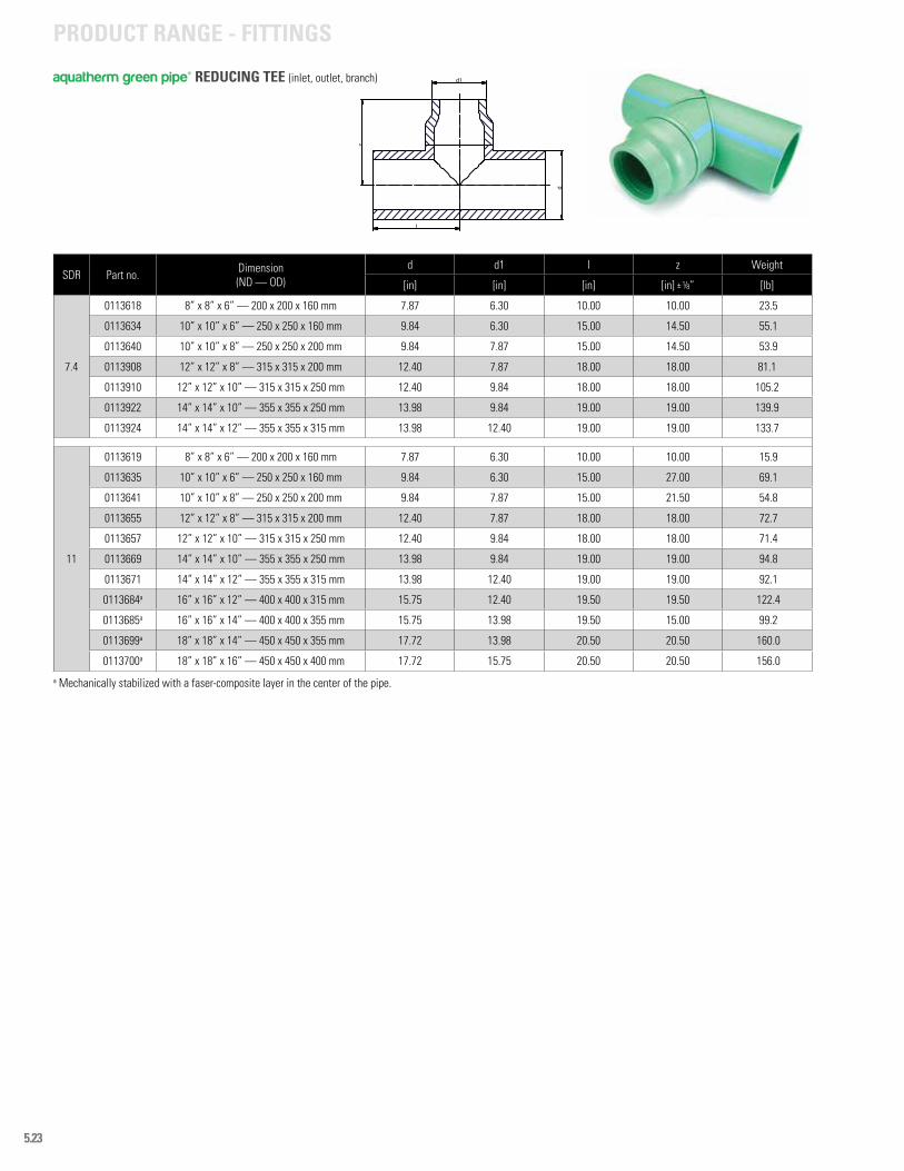
5.23
PRODUCT RANGE - FITTINGS
l
z
d
d1
SDR Part no. Dimension (ND — OD)
d d1 l z Weight
[in] [in] [in] [in] ± 1/8” [lb]
7.4
0113618 8” x 8” x 6” — 200 x 200 x 160 mm 7.87 6.30 10.00 10.00 23.5
0113634 10” x 10” x 6” — 250 x 250 x 160 mm 9.84 6.30 15.00 14.50 55.1
0113640 10” x 10” x 8” — 250 x 250 x 200 mm 9.84 7.87 15.00 14.50 53.9
0113908 12” x 12” x 8” — 315 x 315 x 200 mm 12.40 7.87 18.00 18.00 81.1
0113910 12” x 12” x 10” — 315 x 315 x 250 mm 12.40 9.84 18.00 18.00 105.2
0113922 14” x 14” x 10” — 355 x 355 x 250 mm 13.98 9.84 19.00 19.00 139.9
0113924 14” x 14” x 12” — 355 x 355 x 315 mm 13.98 12.40 19.00 19.00 133.7
11
0113619 8” x 8” x 6” — 200 x 200 x 160 mm 7.87 6.30 10.00 10.00 15.9
0113635 10” x 10” x 6” — 250 x 250 x 160 mm 9.84 6.30 15.00 27.00 69.1
0113641 10” x 10” x 8” — 250 x 250 x 200 mm 9.84 7.87 15.00 21.50 54.8
0113655 12” x 12” x 8” — 315 x 315 x 200 mm 12.40 7.87 18.00 18.00 72.7
0113657 12” x 12” x 10” — 315 x 315 x 250 mm 12.40 9.84 18.00 18.00 71.4
0113669 14” x 14” x 10” — 355 x 355 x 250 mm 13.98 9.84 19.00 19.00 94.8
0113671 14” x 14” x 12” — 355 x 355 x 315 mm 13.98 12.40 19.00 19.00 92.1
0113684a 16” x 16” x 12” — 400 x 400 x 315 mm 15.75 12.40 19.50 19.50 122.4
0113685a 16” x 16” x 14” — 400 x 400 x 355 mm 15.75 13.98 19.50 15.00 99.2
0113699a 18” x 18” x 14” — 450 x 450 x 355 mm 17.72 13.98 20.50 20.50 160.0
0113700a 18” x 18” x 16” — 450 x 450 x 400 mm 17.72 15.75 20.50 20.50 156.0
aquatherm green pipe® REDUCING TEE (inlet, outlet, branch)
a Mechanically stabilized with a faser-composite layer in the center of the pipe.
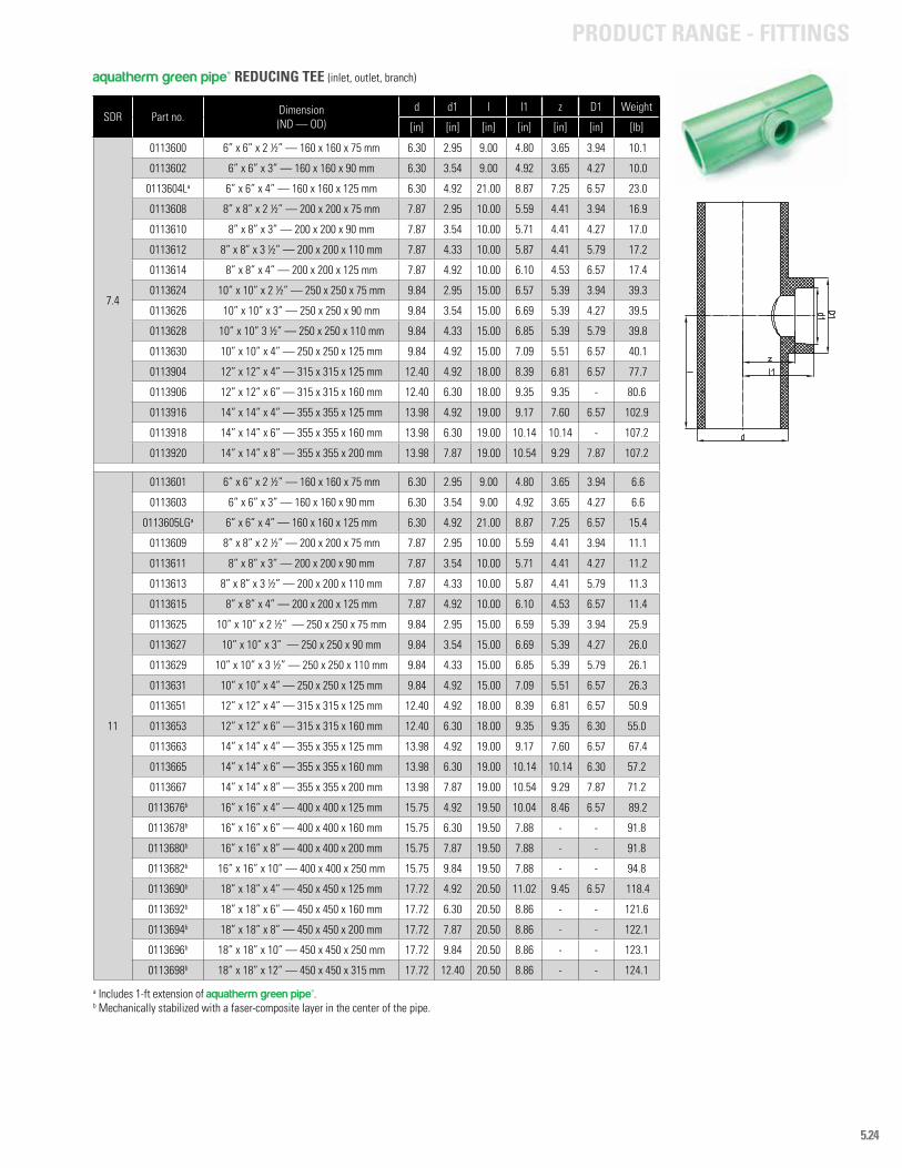
5.24
PRODUCT RANGE - FITTINGS
SDR Part no. Dimension (ND — OD)
d d1 l l1 z D1 Weight
[in] [in] [in] [in] [in] [in] [lb]
7.4
0113600 6” x 6” x 2 ½” — 160 x 160 x 75 mm 6.30 2.95 9.00 4.80 3.65 3.94 10.1
0113602 6” x 6” x 3” — 160 x 160 x 90 mm 6.30 3.54 9.00 4.92 3.65 4.27 10.0
0113604La 6” x 6” x 4” — 160 x 160 x 125 mm 6.30 4.92 21.00 8.87 7.25 6.57 23.0
0113608 8” x 8” x 2 ½” — 200 x 200 x 75 mm 7.87 2.95 10.00 5.59 4.41 3.94 16.9
0113610 8” x 8” x 3” — 200 x 200 x 90 mm 7.87 3.54 10.00 5.71 4.41 4.27 17.0
0113612 8” x 8” x 3 ½” — 200 x 200 x 110 mm 7.87 4.33 10.00 5.87 4.41 5.79 17.2
0113614 8” x 8” x 4” — 200 x 200 x 125 mm 7.87 4.92 10.00 6.10 4.53 6.57 17.4
0113624 10” x 10” x 2 ½” — 250 x 250 x 75 mm 9.84 2.95 15.00 6.57 5.39 3.94 39.3
0113626 10” x 10” x 3” — 250 x 250 x 90 mm 9.84 3.54 15.00 6.69 5.39 4.27 39.5
0113628 10” x 10” 3 ½” — 250 x 250 x 110 mm 9.84 4.33 15.00 6.85 5.39 5.79 39.8
0113630 10” x 10” x 4” — 250 x 250 x 125 mm 9.84 4.92 15.00 7.09 5.51 6.57 40.1
0113904 12” x 12” x 4” — 315 x 315 x 125 mm 12.40 4.92 18.00 8.39 6.81 6.57 77.7
0113906 12” x 12” x 6” — 315 x 315 x 160 mm 12.40 6.30 18.00 9.35 9.35 - 80.6
0113916 14” x 14” x 4” — 355 x 355 x 125 mm 13.98 4.92 19.00 9.17 7.60 6.57 102.9
0113918 14” x 14” x 6” — 355 x 355 x 160 mm 13.98 6.30 19.00 10.14 10.14 - 107.2
0113920 14” x 14” x 8” — 355 x 355 x 200 mm 13.98 7.87 19.00 10.54 9.29 7.87 107.2
11
0113601 6” x 6” x 2 ½” — 160 x 160 x 75 mm 6.30 2.95 9.00 4.80 3.65 3.94 6.6
0113603 6” x 6” x 3” — 160 x 160 x 90 mm 6.30 3.54 9.00 4.92 3.65 4.27 6.6
0113605LGa 6” x 6” x 4” — 160 x 160 x 125 mm 6.30 4.92 21.00 8.87 7.25 6.57 15.4
0113609 8” x 8” x 2 ½” — 200 x 200 x 75 mm 7.87 2.95 10.00 5.59 4.41 3.94 11.1
0113611 8” x 8” x 3” — 200 x 200 x 90 mm 7.87 3.54 10.00 5.71 4.41 4.27 11.2
0113613 8” x 8” x 3 ½” — 200 x 200 x 110 mm 7.87 4.33 10.00 5.87 4.41 5.79 11.3
0113615 8” x 8” x 4” — 200 x 200 x 125 mm 7.87 4.92 10.00 6.10 4.53 6.57 11.4
0113625 10” x 10” x 2 ½” — 250 x 250 x 75 mm 9.84 2.95 15.00 6.59 5.39 3.94 25.9
0113627 10” x 10” x 3” — 250 x 250 x 90 mm 9.84 3.54 15.00 6.69 5.39 4.27 26.0
0113629 10” x 10” x 3 ½” — 250 x 250 x 110 mm 9.84 4.33 15.00 6.85 5.39 5.79 26.1
0113631 10” x 10” x 4” — 250 x 250 x 125 mm 9.84 4.92 15.00 7.09 5.51 6.57 26.3
0113651 12” x 12” x 4” — 315 x 315 x 125 mm 12.40 4.92 18.00 8.39 6.81 6.57 50.9
0113653 12” x 12” x 6” — 315 x 315 x 160 mm 12.40 6.30 18.00 9.35 9.35 6.30 55.0
0113663 14” x 14” x 4” — 355 x 355 x 125 mm 13.98 4.92 19.00 9.17 7.60 6.57 67.4
0113665 14” x 14” x 6” — 355 x 355 x 160 mm 13.98 6.30 19.00 10.14 10.14 6.30 57.2
0113667 14” x 14” x 8” — 355 x 355 x 200 mm 13.98 7.87 19.00 10.54 9.29 7.87 71.2
0113676b 16” x 16” x 4” — 400 x 400 x 125 mm 15.75 4.92 19.50 10.04 8.46 6.57 89.2
0113678b 16” x 16” x 6” — 400 x 400 x 160 mm 15.75 6.30 19.50 7.88 - - 91.8
0113680b 16” x 16” x 8” — 400 x 400 x 200 mm 15.75 7.87 19.50 7.88 - - 91.8
0113682b 16” x 16” x 10” — 400 x 400 x 250 mm 15.75 9.84 19.50 7.88 - - 94.8
0113690b 18” x 18” x 4” — 450 x 450 x 125 mm 17.72 4.92 20.50 11.02 9.45 6.57 118.4
0113692b 18” x 18” x 6” — 450 x 450 x 160 mm 17.72 6.30 20.50 8.86 - - 121.6
0113694b 18” x 18” x 8” — 450 x 450 x 200 mm 17.72 7.87 20.50 8.86 - - 122.1
0113696b 18” x 18” x 10” — 450 x 450 x 250 mm 17.72 9.84 20.50 8.86 - - 123.1
0113698b 18” x 18” x 12” — 450 x 450 x 315 mm 17.72 12.40 20.50 8.86 - - 124.1
aquatherm green pipe® REDUCING TEE (inlet, outlet, branch)
a Includes 1-ft extension of aquatherm green pipe®.b Mechanically stabilized with a faser-composite layer in the center of the pipe.
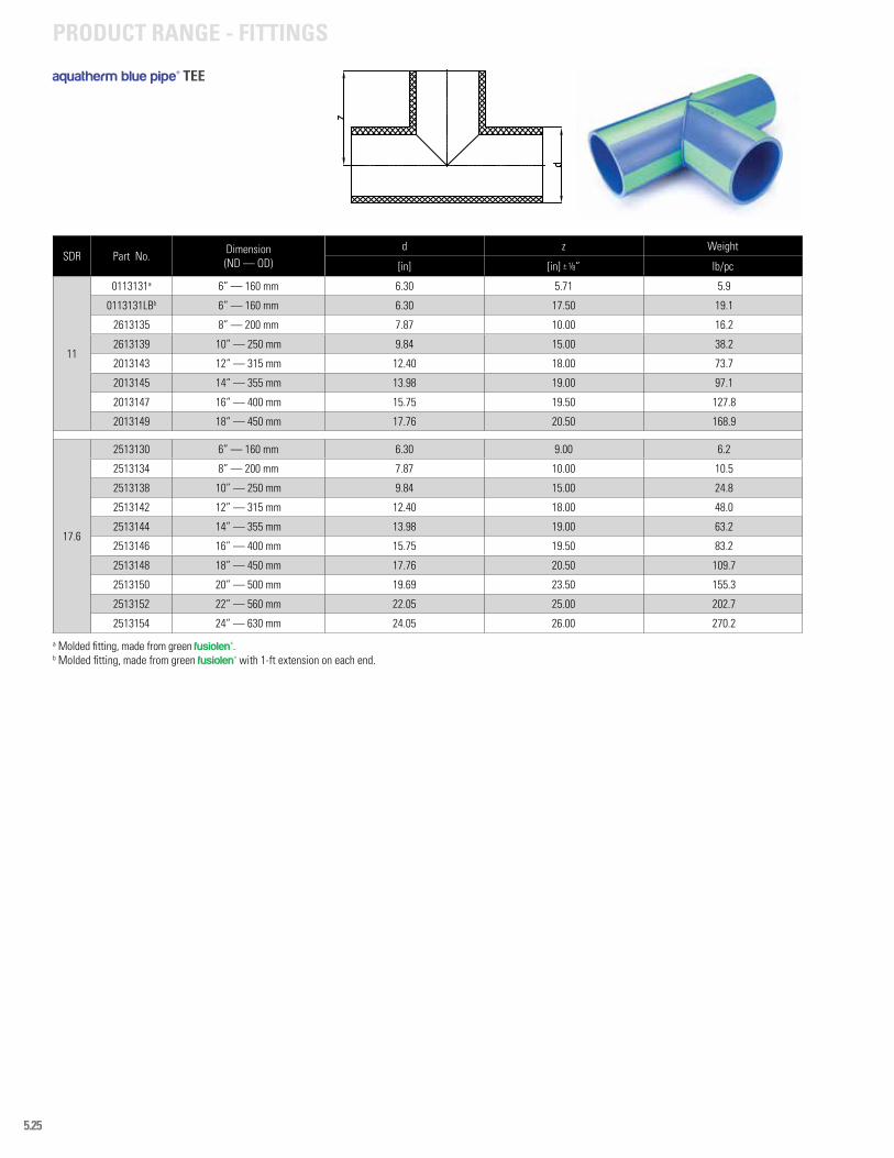
5.25
PRODUCT RANGE - FITTINGS
SDR Part No. Dimension (ND — OD)
d z Weight
[in] [in] ± 1/8” lb/pc
11
0113131a 6” — 160 mm 6.30 5.71 5.9
0113131LBb 6” — 160 mm 6.30 17.50 19.1
2613135 8” — 200 mm 7.87 10.00 16.2
2613139 10” — 250 mm 9.84 15.00 38.2
2013143 12“ — 315 mm 12.40 18.00 73.7
2013145 14“ — 355 mm 13.98 19.00 97.1
2013147 16“ — 400 mm 15.75 19.50 127.8
2013149 18“ — 450 mm 17.76 20.50 168.9
17.6
2513130 6” — 160 mm 6.30 9.00 6.2
2513134 8” — 200 mm 7.87 10.00 10.5
2513138 10” — 250 mm 9.84 15.00 24.8
2513142 12” — 315 mm 12.40 18.00 48.0
2513144 14” — 355 mm 13.98 19.00 63.2
2513146 16” — 400 mm 15.75 19.50 83.2
2513148 18” — 450 mm 17.76 20.50 109.7
2513150 20” — 500 mm 19.69 23.50 155.3
2513152 22” — 560 mm 22.05 25.00 202.7
2513154 24” — 630 mm 24.05 26.00 270.2
aquatherm blue pipe® TEE
a Molded fitting, made from green fusiolen®.b Molded fitting, made from green fusiolen® with 1-ft extension on each end.
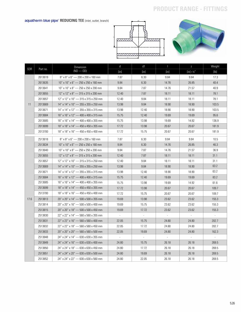
5.26
PRODUCT RANGE - FITTINGS
SDR Part no. Dimension (ND — OD)
d d1 l z Weight
[in] [in] [in] [in] ± 1/8” [lb]
11
2613619 8” x 8” x 6” — 200 x 200 x 160 mm 7.87 6.30 9.84 9.84 17.3
2613635 10” x 10” x 6” — 250 x 250 x 160 mm 9.84 6.30 14.76 26.85 40.4
2613641 10” x 10” x 8” — 250 x 250 x 200 mm 9.84 7.87 14.76 21.57 40.9
2013655 12” x 12” x 8” — 315 x 315 x 200 mm 12.40 7.87 18.11 18.11 78.1
2013657 12” x 12” x 10” — 315 x 315 x 250 mm 12.40 9.84 18.11 18.11 78.1
2013669 14” x 14” x 10” — 355 x 355 x 250 mm 13.98 9.84 18.90 18.90 103.5
2013671 14” x 14” x 12” — 355 x 355 x 315 mm 13.98 12.40 18.90 18.90 103.5
2013684 16” x 16” x 12” — 400 x 400 x 315 mm 15.75 12.40 19.69 19.69 95.6
2013685 16” x 16” x 14” — 400 x 400 x 355 mm 15.75 13.98 19.69 14.92 136.9
2013699 18” x 18” x 14” — 450 x 450 x 355 mm 17.72 13.98 20.67 20.67 181.9
2013700 18” x 18” x 16” — 450 x 450 x 400 mm 17.72 15.75 20.67 20.67 181.9
17.6
2513618 8” x 8” x 6” — 200 x 200 x 160 mm 7.87 6.30 9.84 9.84 10.5
2513634 10” x 10” x 6” — 250 x 250 x 160 mm 9.84 6.30 14.76 26.85 46.3
2513640 10” x 10” x 8” — 250 x 250 x 200 mm 9.84 7.87 14.76 21.57 36.9
2513655 12” x 12” x 8” — 315 x 315 x 200 mm 12.40 7.87 18.11 18.11 31.1
2513657 12” x 12” x 10” — 315 x 315 x 250 mm 12.40 9.84 18.11 18.11 31.1
2513669 14” x 14” x 10” — 355 x 355 x 250 mm 13.98 9.84 18.90 18.90 63.2
2513671 14” x 14” x 12” — 355 x 355 x 315 mm 13.98 12.40 18.90 18.90 63.2
2513684 16” x 16” x 12” — 400 x 400 x 315 mm 15.75 12.40 19.69 19.69 83.2
2513685 16” x 16” x 14” — 400 x 400 x 355 mm 15.75 13.98 19.69 14.92 61.6
2513699 18” x 18” x 14” — 450 x 450 x 355 mm 17.72 13.98 20.67 20.67 109.7
2513700 18” x 18” x 16” — 450 x 450 x 400 mm 17.72 15.75 20.67 20.67 109.7
2513813 20” x 20” x 14” — 500 x 500 x 355 mm 19.69 13.98 23.62 23.62 155.3
2513814 20” x 20” x 16” — 500 x 500 x 400 mm 19.69 15.75 23.62 23.62 155.3
2513815 20” x 20” x 18” — 500 x 500 x 450 mm 19.69 17.72 23.62 23.62 155.3
2513830 22” x 22” x 14” — 560 x 560 x 355 mm - - - - -
2513831 22” x 22” x 16” — 560 x 560 x 400 mm 22.05 15.75 24.80 24.80 202.7
2513832 22” x 22” x 18” — 560 x 560 x 450 mm 22.05 17.72 24.80 24.80 202.7
2513833 20” x 20” x 20” — 560 x 560 x 500 mm 22.05 19.69 24.80 24.80 162.3
2513848 24” x 24” x 14” — 630 x 630 x 355 mm - - - - -
2513849 24” x 24” x 16” — 630 x 630 x 400 mm 24.80 15.75 26.18 26.18 269.5
2513850 24” x 24” x 18” — 630 x 630 x 450 mm 24.80 17.72 26.18 26.18 269.5
2513851 24” x 24” x 20” — 630 x 630 x 500 mm 24.80 19.69 26.18 26.18 269.5
2513852 24” x 24” x 22” — 630 x 630 x 560 mm 24.80 22.05 26.18 26.18 269.5
l
z
d
d1aquatherm blue pipe® REDUCING TEE (inlet, outlet, branch)
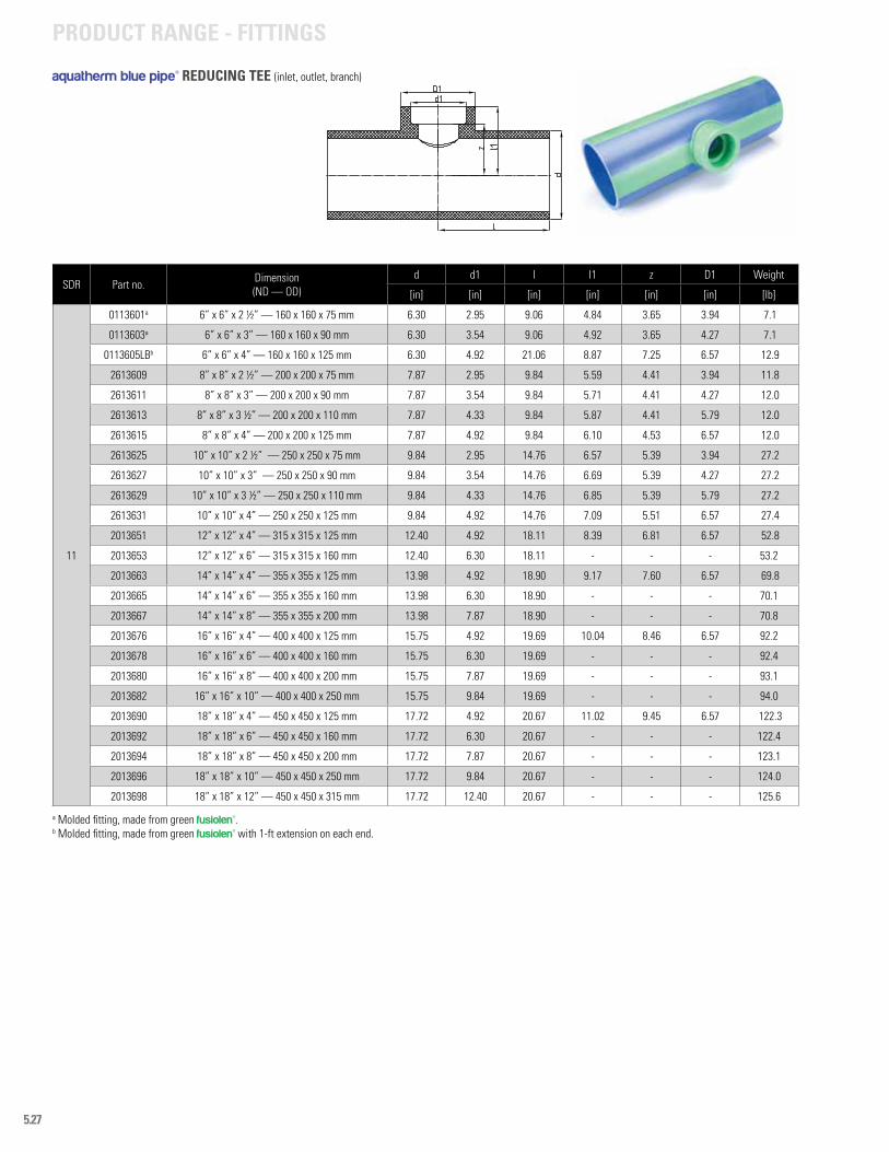
5.27
PRODUCT RANGE - FITTINGS
SDR Part no. Dimension (ND — OD)
d d1 l l1 z D1 Weight
[in] [in] [in] [in] [in] [in] [lb]
11
0113601a 6” x 6” x 2 ½” — 160 x 160 x 75 mm 6.30 2.95 9.06 4.84 3.65 3.94 7.1
0113603a 6” x 6” x 3” — 160 x 160 x 90 mm 6.30 3.54 9.06 4.92 3.65 4.27 7.1
0113605LBb 6” x 6” x 4” — 160 x 160 x 125 mm 6.30 4.92 21.06 8.87 7.25 6.57 12.9
2613609 8” x 8” x 2 ½” — 200 x 200 x 75 mm 7.87 2.95 9.84 5.59 4.41 3.94 11.8
2613611 8” x 8” x 3” — 200 x 200 x 90 mm 7.87 3.54 9.84 5.71 4.41 4.27 12.0
2613613 8” x 8” x 3 ½” — 200 x 200 x 110 mm 7.87 4.33 9.84 5.87 4.41 5.79 12.0
2613615 8” x 8” x 4” — 200 x 200 x 125 mm 7.87 4.92 9.84 6.10 4.53 6.57 12.0
2613625 10” x 10” x 2 ½” — 250 x 250 x 75 mm 9.84 2.95 14.76 6.57 5.39 3.94 27.2
2613627 10” x 10” x 3” — 250 x 250 x 90 mm 9.84 3.54 14.76 6.69 5.39 4.27 27.2
2613629 10” x 10” x 3 ½” — 250 x 250 x 110 mm 9.84 4.33 14.76 6.85 5.39 5.79 27.2
2613631 10” x 10” x 4” — 250 x 250 x 125 mm 9.84 4.92 14.76 7.09 5.51 6.57 27.4
2013651 12” x 12” x 4” — 315 x 315 x 125 mm 12.40 4.92 18.11 8.39 6.81 6.57 52.8
2013653 12” x 12” x 6” — 315 x 315 x 160 mm 12.40 6.30 18.11 - - - 53.2
2013663 14” x 14” x 4” — 355 x 355 x 125 mm 13.98 4.92 18.90 9.17 7.60 6.57 69.8
2013665 14” x 14” x 6” — 355 x 355 x 160 mm 13.98 6.30 18.90 - - - 70.1
2013667 14” x 14” x 8” — 355 x 355 x 200 mm 13.98 7.87 18.90 - - - 70.8
2013676 16” x 16” x 4” — 400 x 400 x 125 mm 15.75 4.92 19.69 10.04 8.46 6.57 92.2
2013678 16” x 16” x 6” — 400 x 400 x 160 mm 15.75 6.30 19.69 - - - 92.4
2013680 16” x 16” x 8” — 400 x 400 x 200 mm 15.75 7.87 19.69 - - - 93.1
2013682 16” x 16” x 10” — 400 x 400 x 250 mm 15.75 9.84 19.69 - - - 94.0
2013690 18” x 18” x 4” — 450 x 450 x 125 mm 17.72 4.92 20.67 11.02 9.45 6.57 122.3
2013692 18” x 18” x 6” — 450 x 450 x 160 mm 17.72 6.30 20.67 - - - 122.4
2013694 18” x 18” x 8” — 450 x 450 x 200 mm 17.72 7.87 20.67 - - - 123.1
2013696 18” x 18” x 10” — 450 x 450 x 250 mm 17.72 9.84 20.67 - - - 124.0
2013698 18” x 18” x 12” — 450 x 450 x 315 mm 17.72 12.40 20.67 - - - 125.6
a Molded fitting, made from green fusiolen®.b Molded fitting, made from green fusiolen® with 1-ft extension on each end.
aquatherm blue pipe® REDUCING TEE (inlet, outlet, branch)
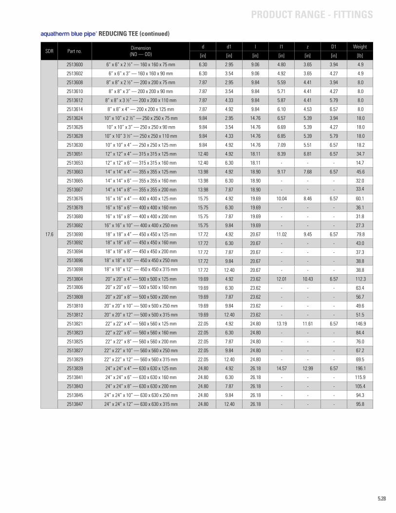
5.28
PRODUCT RANGE - FITTINGS
SDR Part no. Dimension (ND — OD)
d d1 l l1 z D1 Weight
[in] [in] [in] [in] [in] [in] [lb]
17.6
2513600 6” x 6” x 2 ½” — 160 x 160 x 75 mm 6.30 2.95 9.06 4.80 3.65 3.94 4.9
2513602 6” x 6” x 3” — 160 x 160 x 90 mm 6.30 3.54 9.06 4.92 3.65 4.27 4.9
2513608 8” x 8” x 2 ½” — 200 x 200 x 75 mm 7.87 2.95 9.84 5.59 4.41 3.94 8.0
2513610 8” x 8” x 3” — 200 x 200 x 90 mm 7.87 3.54 9.84 5.71 4.41 4.27 8.0
2513612 8” x 8” x 3 ½” — 200 x 200 x 110 mm 7.87 4.33 9.84 5.87 4.41 5.79 8.0
2513614 8” x 8” x 4” — 200 x 200 x 125 mm 7.87 4.92 9.84 6.10 4.53 6.57 8.0
2513624 10” x 10” x 2 ½” — 250 x 250 x 75 mm 9.84 2.95 14.76 6.57 5.39 3.94 18.0
2513626 10” x 10” x 3” — 250 x 250 x 90 mm 9.84 3.54 14.76 6.69 5.39 4.27 18.0
2513628 10” x 10” 3 ½” — 250 x 250 x 110 mm 9.84 4.33 14.76 6.85 5.39 5.79 18.0
2513630 10” x 10” x 4” — 250 x 250 x 125 mm 9.84 4.92 14.76 7.09 5.51 6.57 18.2
2513651 12” x 12” x 4” — 315 x 315 x 125 mm 12.40 4.92 18.11 8.39 6.81 6.57 34.7
2513653 12” x 12” x 6” — 315 x 315 x 160 mm 12.40 6.30 18.11 - - - 14.7
2513663 14” x 14” x 4” — 355 x 355 x 125 mm 13.98 4.92 18.90 9.17 7.68 6.57 45.6
2513665 14” x 14” x 6” — 355 x 355 x 160 mm 13.98 6.30 18.90 - - - 32.0
2513667 14” x 14” x 8” — 355 x 355 x 200 mm 13.98 7.87 18.90 - - - 33.4
2513676 16” x 16” x 4” — 400 x 400 x 125 mm 15.75 4.92 19.69 10.04 8.46 6.57 60.1
2513678 16” x 16” x 6” — 400 x 400 x 160 mm 15.75 6.30 19.69 - - - 36.1
2513680 16” x 16” x 8” — 400 x 400 x 200 mm 15.75 7.87 19.69 - - - 31.8
2513682 16” x 16” x 10” — 400 x 400 x 250 mm 15.75 9.84 19.69 - - - 27.3
2513690 18” x 18” x 4” — 450 x 450 x 125 mm 17.72 4.92 20.67 11.02 9.45 6.57 79.8
2513692 18” x 18” x 6” — 450 x 450 x 160 mm 17.72 6.30 20.67 - - - 43.0
2513694 18” x 18” x 8” — 450 x 450 x 200 mm 17.72 7.87 20.67 - - - 37.3
2513696 18” x 18” x 10” — 450 x 450 x 250 mm 17.72 9.84 20.67 - - - 38.8
2513698 18” x 18” x 12” — 450 x 450 x 315 mm 17.72 12.40 20.67 - - - 38.8
2513804 20” x 20” x 4” — 500 x 500 x 125 mm 19.69 4.92 23.62 12.01 10.43 6.57 112.3
2513806 20” x 20” x 6” — 500 x 500 x 160 mm 19.69 6.30 23.62 - - - 63.4
2513808 20” x 20” x 8” — 500 x 500 x 200 mm 19.69 7.87 23.62 - - - 56.7
2513810 20” x 20” x 10” — 500 x 500 x 250 mm 19.69 9.84 23.62 - - - 49.6
2513812 20” x 20” x 12” — 500 x 500 x 315 mm 19.69 12.40 23.62 - - - 51.5
2513821 22” x 22” x 4” — 560 x 560 x 125 mm 22.05 4.92 24.80 13.19 11.61 6.57 146.9
2513823 22” x 22” x 6” — 560 x 560 x 160 mm 22.05 6.30 24.80 - - - 84.4
2513825 22” x 22” x 8” — 560 x 560 x 200 mm 22.05 7.87 24.80 - - - 76.0
2513827 22” x 22” x 10” — 560 x 560 x 250 mm 22.05 9.84 24.80 - - - 67.2
2513829 22” x 22” x 12” — 560 x 560 x 315 mm 22.05 12.40 24.80 - - - 69.5
2513839 24” x 24” x 4” — 630 x 630 x 125 mm 24.80 4.92 26.18 14.57 12.99 6.57 196.1
2513841 24” x 24” x 6” — 630 x 630 x 160 mm 24.80 6.30 26.18 - - - 115.9
2513843 24” x 24” x 8” — 630 x 630 x 200 mm 24.80 7.87 26.18 - - - 105.4
2513845 24” x 24” x 10” — 630 x 630 x 250 mm 24.80 9.84 26.18 - - - 94.3
2513847 24” x 24” x 12” — 630 x 630 x 315 mm 24.80 12.40 26.18 - - - 95.8
aquatherm blue pipe® REDUCING TEE (continued)
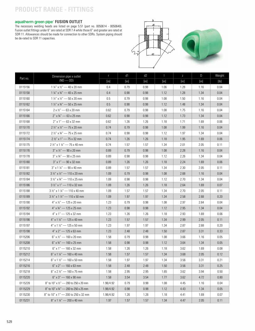
5.29
Part no. Dimension pipe x outlet(ND — OD)
r d1 d2 l z D Weight
[in] [in] [in] [in] [in] [in] [lb]
0115156 1 ¼” x ½” — 40 x 20 mm 0.4 0.79 0.98 1.06 1.28 1.16 0.04
0115158 1 ¼” x ¾” — 40 x 25 mm 0.4 0.98 0.98 1.12 1.28 1.34 0.04
0115160 1 ½” x ½” — 50 x 20 mm 0.5 0.79 0.98 1.08 1.50 1.16 0.04
0115162 1 ½” x ¾” — 50 x 25 mm 0.5 0.98 0.98 1.12 1.48 1.34 0.04
0115164 2 x ½” — 63 x 20 mm 0.62 0.79 0.98 1.08 1.75 1.16 0.04
0115166 2” x ¾” — 63 x 25 mm 0.62 0.98 0.98 1.12 1.73 1.34 0.04
0115168 2” x 1” — 63 x 32 mm 0.62 1.26 1.26 1.18 1.71 1.69 0.06
0115170 2 ½” x ½” — 75 x 20 mm 0.74 0.79 0.98 1.08 1.99 1.16 0.04
0115172 2 ½” x ¾” — 75 x 25 mm 0.74 0.98 0.98 1.12 1.97 1.34 0.04
0115174 2 ½” x 1” — 75 x 32 mm 0.74 1.26 1.26 1.18 1.95 1.69 0.06
0115175 2 ½” x 1 ¼” — 75 x 40 mm 0.74 1.57 1.57 1.34 2.01 2.05 0.11
0115176 3” x ½” — 90 x 20 mm 0.89 0.79 0.98 1.08 2.28 1.16 0.04
0115178 3” x ¾’’ — 90 x 25 mm 0.89 0.98 0.98 1.12 2.26 1.34 0.04
0115180 3” x 1” — 90 x 32 mm 0.89 1.26 1.26 1.18 2.24 1.69 0.06
0115181 3” x 1 ¼” — 90 x 40 mm 0.89 1.57 1.57 1.34 2.30 2.05 0.11
0115182 3 ½” x ½” — 110 x 20 mm 1.09 0.79 0.98 1.08 2.68 1.16 0.04
0115184 3 ½” x ¾” — 110 x 25 mm 1.09 0.98 0.98 1.12 2.70 1.34 0.04
0115186 3 ½” x 1” — 110 x 32 mm 1.09 1.26 1.26 1.18 2.64 1.69 0.07
0115188 3 ½” x 1 ¼” — 110 x 40 mm 1.09 1.57 1.57 1.34 2.70 2.05 0.11
0115189 3 ½” x 1 ½” — 110 x 50 mm 1.09 1.97 1.97 1.34 2.58 2.68 0.20
0115190 4” x ½” — 125 x 20 mm 1.23 0.79 0.98 1.08 2.97 2.64 0.04
0115192 4” x ¾” — 125 x 25 mm 1.23 0.98 0.98 1.12 2.95 1.34 0.04
0115194 4” x 1” — 125 x 32 mm 1.23 1.26 1.26 1.18 2.93 1.69 0.06
0115196 4” x 1 ¼” — 125 x 40 mm 1.23 1.57 1.57 1.34 2.99 2.05 0.11
0115197 4” x 1 ½” — 125 x 50 mm 1.23 1.97 1.97 1.34 2.87 2.68 0.20
0115198 4” x 2’’ — 125 x 63 mm 1.23 2.48 2.48 1.50 2.87 3.31 0.33
0115206 6” x ½” — 160 x 20 mm 1.58 0.79 0.98 1.08 3.66 1.16 0.05
0115208 6” x ¾” — 160 x 25 mm 1.58 0.98 0.98 1.12 3.64 1.34 0.05
0115210 6” x 1” — 160 x 32 mm 1.58 1.26 1.26 1.18 3.62 1.69 0.08
0115212 6” x 1 ¼” — 160 x 40 mm 1.58 1.57 1.57 1.34 3.68 2.05 0.12
0115214 6” x 1 ½” — 160 x 50 mm 1.58 1.97 1.97 1.34 3.56 3.31 0.21
0115216 6” x 2” — 160 x 63 mm 1.58 2.48 2.48 1.50 3.56 3.31 0.25
0115218 6” x 2 ½” — 160 x 75 mm 1.58 2.95 2.95 1.65 3.62 3.94 0.50
0115220 6” x 3” — 160 x 90 mm 1.58 3.54 3.54 1.77 3.62 4.72 0.80
0115228 8” to 10” x ½” — 200 to 250 x 20 mm 1.98/4.92 0.79 0.98 1.08 4.45 1.16 0.04
0115229 8” to 10” x ¾” — 200 to 250 x 25 mm 1.98/4.92 0.98 0.98 1.12 4.43 1.34 0.05
0115230 8” to 10” x 1” — 200 to 250 x 32 mm 1.98/4.92 1.26 1.26 1.18 4.41 1.69 0.07
0115231 8” x 1 ¼” — 200 x 40 mm 1.97 1.57 1.57 1.34 4.47 2.05 0.11
aquatherm green pipe® FUSION OUTLET
PRODUCT RANGE - FITTINGS
The necessary welding heads are listed on page 5.51 (part no. 0050614 - 0050640). Fusion outlet fittings under 6” are rated at SDR 7.4 while those 6” and greater are rated at SDR 11. Allowances should be made for connection to other SDRs. System piping should be de-rated to SDR 11 capacities.
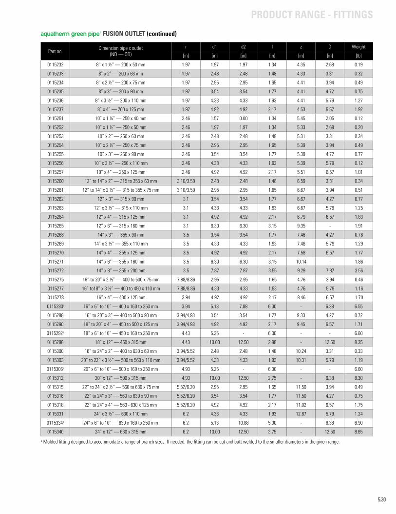
5.30
Part no. Dimension pipe x outlet(ND — OD)
r d1 d2 l z D Weight
[in] [in] [in] [in] [in] [in] [lb]
0115232 8” x 1 ½” — 200 x 50 mm 1.97 1.97 1.97 1.34 4.35 2.68 0.19
0115233 8” x 2” — 200 x 63 mm 1.97 2.48 2.48 1.48 4.33 3.31 0.32
0115234 8” x 2 ½” — 200 x 75 mm 1.97 2.95 2.95 1.65 4.41 3.94 0.49
0115235 8” x 3” — 200 x 90 mm 1.97 3.54 3.54 1.77 4.41 4.72 0.75
0115236 8” x 3 ½” — 200 x 110 mm 1.97 4.33 4.33 1.93 4.41 5.79 1.27
0115237 8” x 4” — 200 x 125 mm 1.97 4.92 4.92 2.17 4.53 6.57 1.92
0115251 10” x 1 ¼” — 250 x 40 mm 2.46 1.57 0.00 1.34 5.45 2.05 0.12
0115252 10” x 1 ½” — 250 x 50 mm 2.46 1.97 1.97 1.34 5.33 2.68 0.20
0115253 10” x 2” — 250 x 63 mm 2.46 2.48 2.48 1.48 5.31 3.31 0.34
0115254 10” x 2 ½” — 250 x 75 mm 2.46 2.95 2.95 1.65 5.39 3.94 0.49
0115255 10” x 3” — 250 x 90 mm 2.46 3.54 3.54 1.77 5.39 4.72 0.77
0115256 10” x 3 ½” — 250 x 110 mm 2.46 4.33 4.33 1.93 5.39 5.79 0.12
0115257 10” x 4” — 250 x 125 mm 2.46 4.92 4.92 2.17 5.51 6.57 1.81
0115260 12” to 14” x 2” — 315 to 355 x 63 mm 3.10/3.50 2.48 2.48 1.48 6.59 3.31 0.34
0115261 12” to 14” x 2 ½” — 315 to 355 x 75 mm 3.10/3.50 2.95 2.95 1.65 6.67 3.94 0.51
0115262 12” x 3” — 315 x 90 mm 3.1 3.54 3.54 1.77 6.67 4.27 0.77
0115263 12” x 3 ½” — 315 x 110 mm 3.1 4.33 4.33 1.93 6.67 5.79 1.25
0115264 12” x 4” — 315 x 125 mm 3.1 4.92 4.92 2.17 6.79 6.57 1.83
0115265 12” x 6” — 315 x 160 mm 3.1 6.30 6.30 3.15 9.35 - 1.91
0115268 14” x 3” — 355 x 90 mm 3.5 3.54 3.54 1.77 7.46 4.27 0.78
0115269 14” x 3 ½” — 355 x 110 mm 3.5 4.33 4.33 1.93 7.46 5.79 1.29
0115270 14” x 4” — 355 x 125 mm 3.5 4.92 4.92 2.17 7.58 6.57 1.77
0115271 14” x 6” — 355 x 160 mm 3.5 6.30 6.30 3.15 10.14 - 1.86
0115272 14” x 8” — 355 x 200 mm 3.5 7.87 7.87 3.55 9.29 7.87 3.56
0115275 16” to 20” x 2 ½” — 400 to 500 x 75 mm 7.88/8.86 2.95 2.95 1.65 4.76 3.94 0.46
0115277 16” to18” x 3 ½” — 400 to 450 x 110 mm 7.88/8.86 4.33 4.33 1.93 4.76 5.79 1.16
0115278 16” x 4” — 400 x 125 mm 3.94 4.92 4.92 2.17 8.46 6.57 1.70
0115280a 16” x 6” to 10” — 400 x 160 to 250 mm 3.94 5.13 7.88 6.00 - 6.38 6.55
0115288 16” to 20” x 3” — 400 to 500 x 90 mm 3.94/4.93 3.54 3.54 1.77 9.33 4.27 0.72
0115290 18” to 20” x 4” — 450 to 500 x 125 mm 3.94/4.93 4.92 4.92 2.17 9.45 6.57 1.71
0115292a 18” x 6” to 10” — 450 x 160 to 250 mm 4.43 5.25 - 6.00 - - 6.60
0115298 18” x 12” — 450 x 315 mm 4.43 10.00 12.50 2.88 - 12.50 8.35
0115300 16” to 24” x 2” — 400 to 630 x 63 mm 3.94/5.52 2.48 2.48 1.48 10.24 3.31 0.33
0115303 20” to 22” x 3 ½” — 500 to 560 x 110 mm 3.94/5.52 4.33 4.33 1.93 10.31 5.79 1.19
0115306a 20” x 6” to 10” — 500 x 160 to 250 mm 4.93 5.25 - 6.00 - - 6.60
0115312 20” x 12” — 500 x 315 mm 4.93 10.00 12.50 2.75 - 6.38 8.30
0115315 22” to 24” x 2 ½” — 560 to 630 x 75 mm 5.52/6.20 2.95 2.95 1.65 11.50 3.94 0.49
0115316 22” to 24” x 3” — 560 to 630 x 90 mm 5.52/6.20 3.54 3.54 1.77 11.50 4.27 0.75
0115318 22” to 24” x 4” — 560 - 630 x 125 mm 5.52/6.20 4.92 4.92 2.17 11.02 6.57 1.75
0115331 24” x 3 ½” — 630 x 110 mm 6.2 4.33 4.33 1.93 12.87 5.79 1.24
0115334a 24” x 6” to 10” — 630 x 160 to 250 mm 6.2 5.13 10.88 5.00 - 6.38 6.90
0115340 24” x 12” — 630 x 315 mm 6.2 10.00 12.50 3.75 - 12.50 8.65
aquatherm green pipe® FUSION OUTLET (continued)
PRODUCT RANGE - FITTINGS
a Molded fitting designed to accommodate a range of branch sizes. If needed, the fitting can be cut and butt welded to the smaller diameters in the given range.
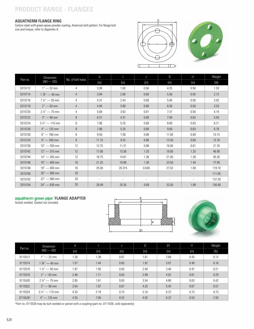
5.31
Part no. Dimension (ND — OD)
d l z D D1 l1 Weight
[in] [in] [in] [in] [in] [in] [lb]
0115512 1” — 32 mm 1.26 1.38 0.67 1.61 2.68 0.43 0.12
0115514 1 ¼” — 40 mm 1.57 1.44 0.65 1.97 3.07 0.49 0.16
0115516 1 ½” — 50 mm 1.97 1.56 0.63 2.40 3.46 0.47 0.21
0115518 2” — 63 mm 2.48 1.71 0.63 2.99 4.02 0.61 0.29
0115520 2 ½” — 75 mm 2.95 1.81 0.63 3.54 4.80 0.63 0.42
0115522 3” — 90 mm 3.54 1.97 0.67 4.25 5.43 0.67 0.57
0115524 3 ½” — 110 mm 4.33 2.19 0.73 5.16 6.22 0.73 0.73
0115526a 4” — 125 mm 4.35 7.95 0.52 4.92 6.22 0.53 2.93
z
a Part no. 0115526 may be butt welded or paired with a coupling (part no. 0111026, sold separately).
aquatherm green pipe® FLANGE ADAPTER Socket welded. Gasket not included.
Part no. Dimension (ND — OD) No. of bolt holes
d l z D z1 Weight
[in] [in] [in] [in] [in] [lb]
3315712 1” — 32 mm 4 3.38 1.63 0.56 4.25 0.50 1.53
3315714 1 ¼” — 40 mm 4 3.94 2.00 0.69 5.56 0.50 2.73
3315716 1 ½” — 50 mm 4 4.31 2.44 0.69 5.94 0.50 3.03
3315718 2” — 63 mm 4 4.94 3.06 0.69 6.56 0.50 3.53
3315720 2 ½” — 75 mm 4 5.69 3.63 0.81 7.31 0.50 4.19
3315722 3” — 90 mm 8 6.31 4.31 0.69 7.94 0.63 5.45
3315724 3 ½” — 110 mm 8 7.06 5.25 0.69 8.69 0.63 6.21
3315726 4” — 125 mm 8 7.06 5.25 0.69 9.00 0.63 6.78
3315730 6” — 160 mm 8 9.50 7.00 0.88 11.00 0.69 10.15
3315734 8” — 200 mm 8 11.75 9.25 0.88 13.50 0.69 13.70
3315738 10” — 250 mm 12 13.75 11.31 0.88 16.00 0.81 21.35
3315742 12” — 315 mm 12 17.00 13.38 1.25 19.00 1.25 46.95
3315744 14” — 355 mm 12 18.75 14.81 1.38 21.00 1.38 45.35
3315746 16” — 400 mm 16 21.25 16.88 1.38 23.50 1.44 77.95
3315748 18” — 450 mm 16 25.00 20.315 0.630 27.52 1.69 119.10
3315750 20” — 500 mm 20 - - - - - 111.65
3315752 22” — 560 mm 20 - - - - - 137.20
3315754 24” — 630 mm 20 29.49 25.35 0.69 32.05 1.89 150.40
AQUATHERM FLANGE RINGCarbon steel with green epoxy powder coating, American bolt pattern. For flange bolt size and torque, refer to Appendix A.
PRODUCT RANGE - FLANGES
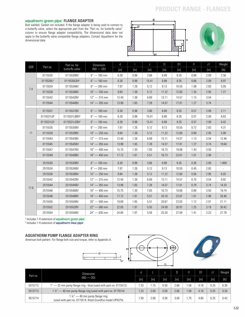
5.32
SDR Part no. Part no. forbutterfly valve
Dimension (ND — OD)
d l z D D1 l1 z1 Weight
[in] [in] [in] [in] [in] [in] [in] [lb]
7.4
0115530 0115530BV 6” — 160 mm 6.30 0.98 3.66 6.89 8.35 0.86 2.09 2.56
0115530La 0115530LBVa 6” — 160 mm 6.30 0.98 15.41 6.89 8.35 0.86 2.09 8.97
0115534 0115534BV 8” — 200 mm 7.87 1.26 5.12 9.13 10.55 1.08 2.83 5.05
0115538 0115538BV 10” — 250 mm 9.84 1.38 5.12 11.22 12.60 1.35 2.95 7.27
0115542 0115542BV 12” — 315 mm 12.40 1.38 6.69 13.11 14.57 1.13 3.54 -
0115544 0115544BV 14” — 355 mm 13.98 1.65 7.28 14.57 17.01 1.27 3.74 -
11
0115531 0115531BV 6” — 160 mm 6.30 0.98 3.66 6.89 8.35 0.57 2.09 2.11
0115531LBb 0115531LBBVb 6” — 160 mm 6.30 0.98 15.41 6.89 8.35 0.57 2.09 6.63
0115531LGa 0115531LGBVa 6” — 160 mm 6.30 0.98 15.41 6.89 8.35 0.57 2.09 6.42
0115535 0115535BV 8” — 200 mm 7.87 1.26 5.12 9.13 10.55 0.72 2.83 4.31
0115539 0115539BV 10” — 250 mm 9.84 1.38 5.12 11.22 12.60 0.89 2.95 5.99
0115543 0115543BV 12” — 315 mm 12.40 1.38 6.69 13.11 14.57 1.13 3.54 12.46
0115545 0115545BV 14” — 355 mm 13.98 1.65 7.28 14.57 17.01 1.27 3.74 19.84
0115547 0115547BV 16” — 400 mm 15.75 1.30 7.83 16.73 19.06 1.43 3.50 -
0115549 0115549BV 18” — 450 mm 17.72 1.81 5.51 16.73 23.07 1.01 2.99 -
17.6
2515530 2515530BV 6” — 160 mm 6.30 0.98 3.66 6.89 8.35 0.36 2.09 1.809
2515534 2515534BV 8” — 200 mm 7.87 1.26 5.12 9.13 10.55 0.45 2.83 -
2515538 2515538BV 10” — 250 mm 9.84 1.38 5.12 11.22 12.60 0.56 2.95 6.03
2515542 2515542BV 12” — 315 mm 12.40 1.38 6.69 13.11 14.57 0.70 3.54 9.92
2515544 2515544BV 14” — 355 mm 13.98 1.65 7.28 14.57 17.01 0.79 3.74 14.33
2515546 2515546BV 16” — 400 mm 15.75 1.30 7.83 16.73 19.06 0.89 3.50 18.74
2515548 2515548BV 18” — 450 mm 17.72 1.81 5.51 20.16 23.07 1.01 2.99 26.46
2515550 2515550BV 20” — 500 mm 19.69 1.85 5.51 20.67 23.03 1.12 2.91 21.11
2515552 2515552BV 22” — 560 mm 22.05 1.97 5.55 24.09 26.97 1.25 3.19 30.42
2515554 2515554BV 24” — 630 mm 24.80 1.97 5.59 25.20 27.09 1.41 3.23 27.78
d1
l1dD
z
lz1
PRODUCT RANGE - FLANGES
aquatherm green pipe® FLANGE ADAPTER Butt welded. Gasket not included. If the flange adapter is being used to connect to a butterfly valve, select the appropriate part from the “Part no. for butterfly valve” column to ensure flange adapter compatibility. The dimensional data does not apply to the butterfly valve compatible flange adapters. Contact Aquatherm for the dimensional data.
a Includes 1-ft extension of aquatherm green pipe®.b Includes 1-ft extension of aquatherm blue pipe®.
Part no. Dimension (ND — OD)
d L z D l1 D1 z1 Weight
[in] [in] [in] [in] [in] [in] [in] [lb]
5515712 1” — 32 mm pump flange ring - blue (used with part no. 0115512) 1.33 1.75 0.50 2.66 1.58 4.18 0.25 0.36
5515713 1 ¼” — 40 mm pump flange ring (used with part no. 0115514) 1.33 2.00 0.50 2.66 1.58 4.18 0.25 0.30
5515714 1 ¼” — 40 mm pump flange ring(used with part no. 0115514, fitted Grundfos model UP4375) 1.50 2.00 0.50 3.00 1.75 4.80 0.25 0.43
AQUATHERM PUMP FLANGE ADAPTER RINGAmerican bolt pattern. For flange bolt size and torque, refer to Appendix A.
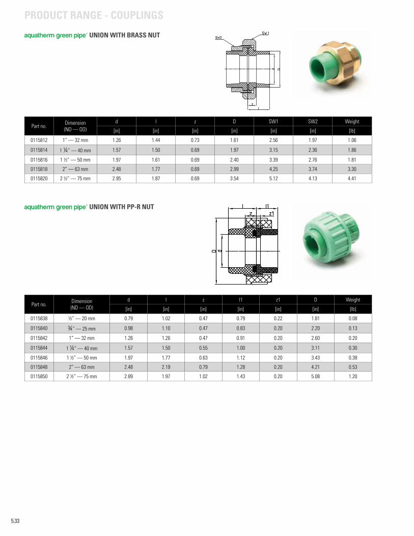
5.33
Part no. Dimension (ND — OD)
d l z D SW1 SW2 Weight
[in] [in] [in] [in] [in] [in] [lb]
0115812 1” — 32 mm 1.26 1.44 0.73 1.61 2.56 1.97 1.06
0115814 1 ¼” — 40 mm 1.57 1.50 0.69 1.97 3.15 2.36 1.86
0115816 1 ½” — 50 mm 1.97 1.61 0.69 2.40 3.39 2.76 1.81
0115818 2” — 63 mm 2.48 1.77 0.69 2.99 4.25 3.74 3.30
0115820 2 ½” — 75 mm 2.95 1.87 0.69 3.54 5.12 4.13 4.41
Part no. Dimension (ND — OD)
d l z l1 z1 D Weight
[in] [in] [in] [in] [in] [in] [lb]
0115838 ½” — 20 mm 0.79 1.02 0.47 0.79 0.22 1.81 0.08
0115840 ¾” — 25 mm 0.98 1.10 0.47 0.83 0.20 2.20 0.13
0115842 1” — 32 mm 1.26 1.26 0.47 0.91 0.20 2.60 0.20
0115844 1 ¼” — 40 mm 1.57 1.50 0.55 1.00 0.20 3.11 0.30
0115846 1 ½” — 50 mm 1.97 1.77 0.63 1.12 0.20 3.43 0.38
0115848 2” — 63 mm 2.48 2.19 0.79 1.28 0.20 4.21 0.53
0115850 2 ½” — 75 mm 2.89 1.97 1.02 1.43 0.20 5.08 1.20
aquatherm green pipe® UNION WITH BRASS NUT
aquatherm green pipe® UNION WITH PP-R NUT
PRODUCT RANGE - COUPLINGS
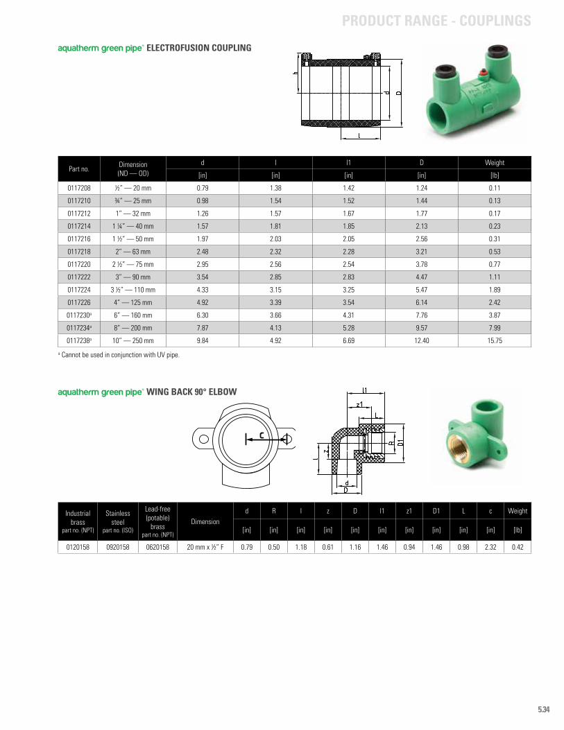
5.34
Part no. Dimension (ND — OD)
d l l1 D Weight
[in] [in] [in] [in] [lb]
0117208 ½” — 20 mm 0.79 1.38 1.42 1.24 0.11
0117210 ¾” — 25 mm 0.98 1.54 1.52 1.44 0.13
0117212 1” — 32 mm 1.26 1.57 1.67 1.77 0.17
0117214 1 ¼” — 40 mm 1.57 1.81 1.85 2.13 0.23
0117216 1 ½” — 50 mm 1.97 2.03 2.05 2.56 0.31
0117218 2” — 63 mm 2.48 2.32 2.28 3.21 0.53
0117220 2 ½” — 75 mm 2.95 2.56 2.54 3.78 0.77
0117222 3” — 90 mm 3.54 2.85 2.83 4.47 1.11
0117224 3 ½” — 110 mm 4.33 3.15 3.25 5.47 1.89
0117226 4” — 125 mm 4.92 3.39 3.54 6.14 2.42
0117230a 6” — 160 mm 6.30 3.66 4.31 7.76 3.87
0117234a 8” — 200 mm 7.87 4.13 5.28 9.57 7.99
0117238a 10” — 250 mm 9.84 4.92 6.69 12.40 15.75
a Cannot be used in conjunction with UV pipe.
Industrial brass
part no. (NPT)
Stainless steel
part no. (ISO)
Lead-free (potable)
brasspart no. (NPT)
Dimension d R l z D l1 z1 D1 L c Weight
[in] [in] [in] [in] [in] [in] [in] [in] [in] [in] [lb]
0120158 0920158 0620158 20 mm x ½” F 0.79 0.50 1.18 0.61 1.16 1.46 0.94 1.46 0.98 2.32 0.42
aquatherm green pipe® ELECTROFUSION COUPLING
aquatherm green pipe® WING BACK 90° ELBOW
PRODUCT RANGE - COUPLINGS
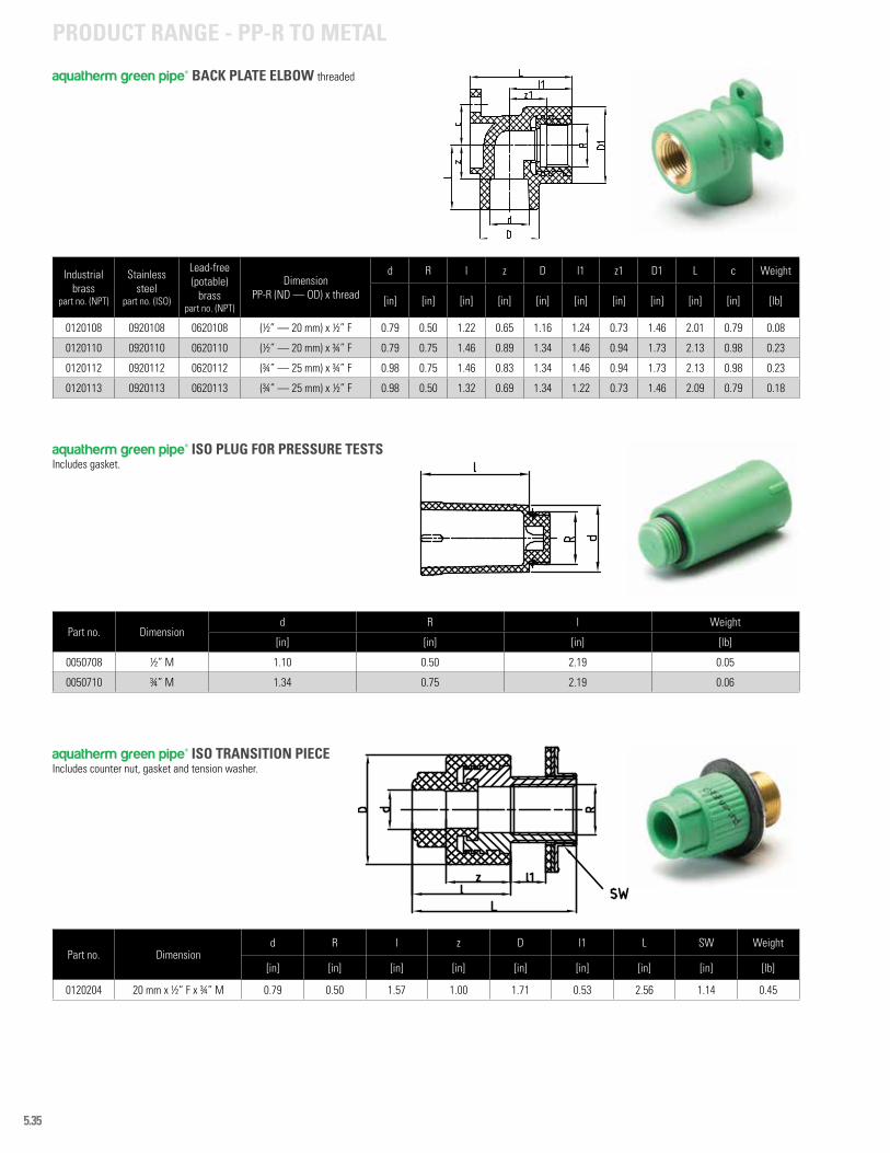
5.35
Part no. Dimension d R l Weight
[in] [in] [in] [lb]
0050708 ½” M 1.10 0.50 2.19 0.05
0050710 ¾” M 1.34 0.75 2.19 0.06
Part no. Dimension d R l z D l1 L SW Weight
[in] [in] [in] [in] [in] [in] [in] [in] [lb]
0120204 20 mm x ½” F x ¾” M 0.79 0.50 1.57 1.00 1.71 0.53 2.56 1.14 0.45
aquatherm green pipe® ISO PLUG FOR PRESSURE TESTSIncludes gasket.
aquatherm green pipe® ISO TRANSITION PIECEIncludes counter nut, gasket and tension washer.
Industrial brass
part no. (NPT)
Stainless steel
part no. (ISO)
Lead-free (potable)
brasspart no. (NPT)
Dimension PP-R (ND — OD) x thread
d R l z D l1 z1 D1 L c Weight
[in] [in] [in] [in] [in] [in] [in] [in] [in] [in] [lb]
0120108 0920108 0620108 (½” — 20 mm) x ½” F 0.79 0.50 1.22 0.65 1.16 1.24 0.73 1.46 2.01 0.79 0.08
0120110 0920110 0620110 (½” — 20 mm) x ¾” F 0.79 0.75 1.46 0.89 1.34 1.46 0.94 1.73 2.13 0.98 0.23
0120112 0920112 0620112 (¾” — 25 mm) x ¾” F 0.98 0.75 1.46 0.83 1.34 1.46 0.94 1.73 2.13 0.98 0.23
0120113 0920113 0620113 (¾” — 25 mm) x ½” F 0.98 0.50 1.32 0.69 1.34 1.22 0.73 1.46 2.09 0.79 0.18
aquatherm green pipe® BACK PLATE ELBOW threaded
PRODUCT RANGE - PP-R TO METAL
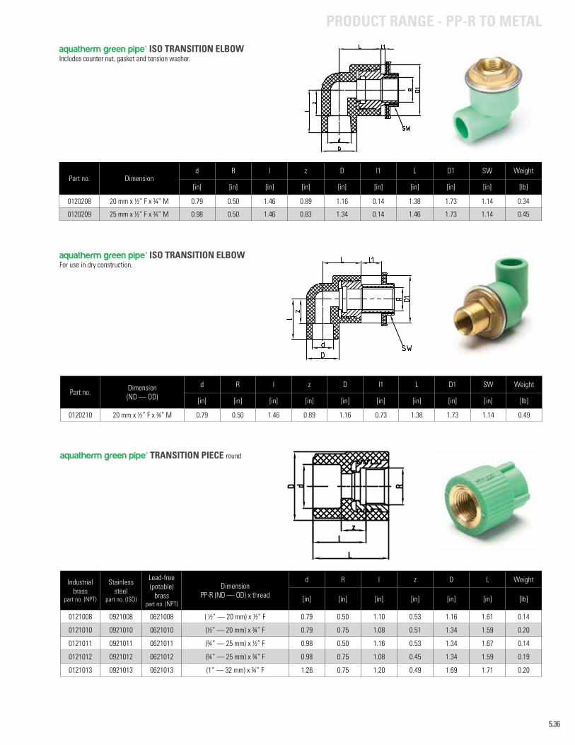
5.36
Part no. Dimension d R l z D l1 L D1 SW Weight
[in] [in] [in] [in] [in] [in] [in] [in] [in] [lb]
0120208 20 mm x ½” F x ¾” M 0.79 0.50 1.46 0.89 1.16 0.14 1.38 1.73 1.14 0.34
0120209 25 mm x ½” F x ¾” M 0.98 0.50 1.46 0.83 1.34 0.14 1.46 1.73 1.14 0.45
Part no. Dimension (ND — OD)
d R l z D l1 L D1 SW Weight
[in] [in] [in] [in] [in] [in] [in] [in] [in] [lb]
0120210 20 mm x ½” F x ¾” M 0.79 0.50 1.46 0.89 1.16 0.73 1.38 1.73 1.14 0.49
Industrial brass
part no. (NPT)
Stainless steel
part no. (ISO)
Lead-free (potable)
brasspart no. (NPT)
Dimension PP-R (ND — OD) x thread
d R l z D L Weight
[in] [in] [in] [in] [in] [in] [lb]
0121008 0921008 0621008 ( ½” — 20 mm) x ½” F 0.79 0.50 1.10 0.53 1.16 1.61 0.14
0121010 0921010 0621010 (½” — 20 mm) x ¾” F 0.79 0.75 1.08 0.51 1.34 1.59 0.20
0121011 0921011 0621011 (¾” — 25 mm) x ½” F 0.98 0.50 1.16 0.53 1.34 1.67 0.14
0121012 0921012 0621012 (¾” — 25 mm) x ¾” F 0.98 0.75 1.08 0.45 1.34 1.59 0.19
0121013 0921013 0621013 (1” — 32 mm) x ¾” F 1.26 0.75 1.20 0.49 1.69 1.71 0.20
aquatherm green pipe® ISO TRANSITION ELBOWIncludes counter nut, gasket and tension washer.
aquatherm green pipe® ISO TRANSITION ELBOW For use in dry construction.
aquatherm green pipe® TRANSITION PIECE round
PRODUCT RANGE - PP-R TO METAL
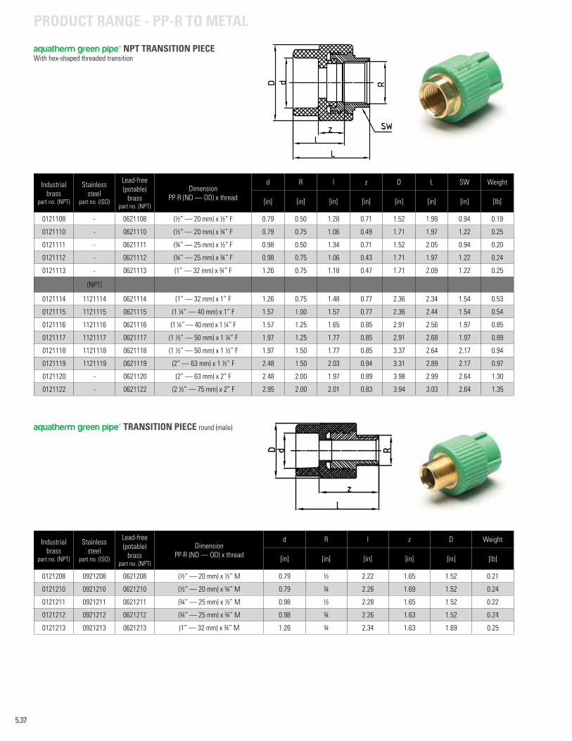
5.37
Industrial brass
part no. (NPT)
Stainless steel
part no. (ISO)
Lead-free (potable)
brasspart no. (NPT)
Dimension PP-R (ND — OD) x thread
d R l z D Weight
[in] [in] [in] [in] [in] [lb]
0121208 0921208 0621208 (½” — 20 mm) x ½” M 0.79 ½ 2.22 1.65 1.52 0.21
0121210 0921210 0621210 (½” — 20 mm) x ¾” M 0.79 ¾ 2.26 1.69 1.52 0.24
0121211 0921211 0621211 (¾” — 25 mm) x ½” M 0.98 ½ 2.28 1.65 1.52 0.22
0121212 0921212 0621212 (¾” — 25 mm) x ¾” M 0.98 ¾ 2.26 1.63 1.52 0.24
0121213 0921213 0621213 (1” — 32 mm) x ¾” M 1.26 ¾ 2.34 1.63 1.69 0.25
Industrial brass
part no. (NPT)
Stainless steel
part no. (ISO)
Lead-free (potable)
brasspart no. (NPT)
Dimension PP-R (ND — OD) x thread
d R l z D L SW Weight
[in] [in] [in] [in] [in] [in] [in] [lb]
0121108 - 0621108 (½” — 20 mm) x ½” F 0.79 0.50 1.28 0.71 1.52 1.99 0.94 0.19
0121110 - 0621110 (½” — 20 mm) x ¾” F 0.79 0.75 1.06 0.49 1.71 1.97 1.22 0.25
0121111 - 0621111 (¾” — 25 mm) x ½” F 0.98 0.50 1.34 0.71 1.52 2.05 0.94 0.20
0121112 - 0621112 (¾” — 25 mm) x ¾” F 0.98 0.75 1.06 0.43 1.71 1.97 1.22 0.24
0121113 - 0621113 (1” — 32 mm) x ¾” F 1.26 0.75 1.18 0.47 1.71 2.09 1.22 0.25
(NPT)
0121114 1121114 0621114 (1” — 32 mm) x 1” F 1.26 0.75 1.48 0.77 2.36 2.34 1.54 0.53
0121115 1121115 0621115 (1 ¼” — 40 mm) x 1” F 1.57 1.00 1.57 0.77 2.36 2.44 1.54 0.54
0121116 1121116 0621116 (1 ¼” — 40 mm) x 1 ¼” F 1.57 1.25 1.65 0.85 2.91 2.56 1.97 0.85
0121117 1121117 0621117 (1 ½” — 50 mm) x 1 ¼” F 1.97 1.25 1.77 0.85 2.91 2.68 1.97 0.89
0121118 1121118 0621118 (1 ½” — 50 mm) x 1 ½” F 1.97 1.50 1.77 0.85 3.37 2.64 2.17 0.94
0121119 1121119 0621119 (2” — 63 mm) x 1 ½” F 2.48 1.50 2.03 0.94 3.31 2.89 2.17 0.97
0121120 - 0621120 (2” — 63 mm) x 2” F 2.48 2.00 1.97 0.89 3.98 2.99 2.64 1.30
0121122 - 0621122 (2 ½” — 75 mm) x 2” F 2.95 2.00 2.01 0.83 3.94 3.03 2.64 1.35
aquatherm green pipe® NPT TRANSITION PIECEWith hex-shaped threaded transition
aquatherm green pipe® TRANSITION PIECE round (male)
PRODUCT RANGE - PP-R TO METAL
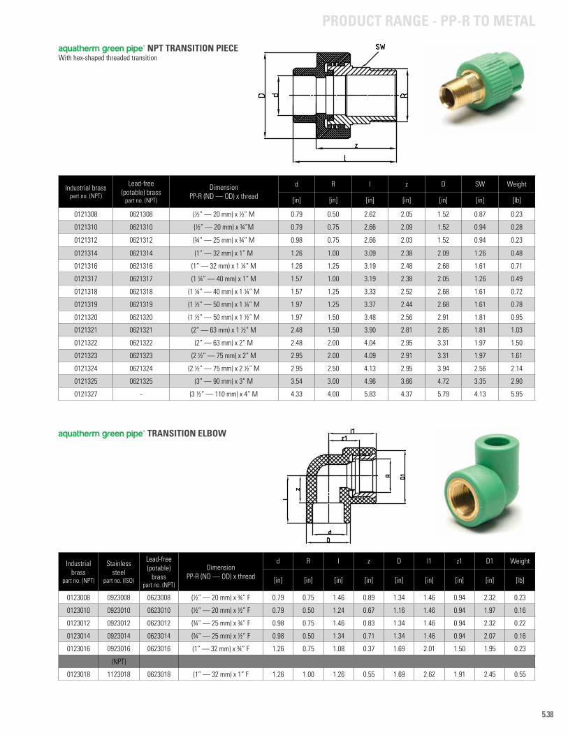
5.38
Industrial brass
part no. (NPT)
Stainless steel
part no. (ISO)
Lead-free (potable)
brasspart no. (NPT)
Dimension PP-R (ND — OD) x thread
d R l z D l1 z1 D1 Weight
[in] [in] [in] [in] [in] [in] [in] [in] [lb]
0123008 0923008 0623008 (½” — 20 mm) x ¾” F 0.79 0.75 1.46 0.89 1.34 1.46 0.94 2.32 0.23
0123010 0923010 0623010 (½” — 20 mm) x ½” F 0.79 0.50 1.24 0.67 1.16 1.46 0.94 1.97 0.16
0123012 0923012 0623012 (¾” — 25 mm) x ¾” F 0.98 0.75 1.46 0.83 1.34 1.46 0.94 2.32 0.22
0123014 0923014 0623014 (¾” — 25 mm) x ½” F 0.98 0.50 1.34 0.71 1.34 1.46 0.94 2.07 0.16
0123016 0923016 0623016 (1” — 32 mm) x ¾” F 1.26 0.75 1.08 0.37 1.69 2.01 1.50 1.95 0.23
(NPT)
0123018 1123018 0623018 (1” — 32 mm) x 1” F 1.26 1.00 1.26 0.55 1.69 2.62 1.91 2.45 0.55
Industrial brasspart no. (NPT)
Lead-free (potable) brass
part no. (NPT)
Dimension PP-R (ND — OD) x thread
d R l z D SW Weight
[in] [in] [in] [in] [in] [in] [lb]
0121308 0621308 (½” — 20 mm) x ½” M 0.79 0.50 2.62 2.05 1.52 0.87 0.23
0121310 0621310 (½” — 20 mm) x ¾”M 0.79 0.75 2.66 2.09 1.52 0.94 0.28
0121312 0621312 (¾” — 25 mm) x ¾” M 0.98 0.75 2.66 2.03 1.52 0.94 0.23
0121314 0621314 (1” — 32 mm) x 1” M 1.26 1.00 3.09 2.38 2.09 1.26 0.48
0121316 0621316 (1” — 32 mm) x 1 ¼” M 1.26 1.25 3.19 2.48 2.68 1.61 0.71
0121317 0621317 (1 ¼” — 40 mm) x 1” M 1.57 1.00 3.19 2.38 2.05 1.26 0.49
0121318 0621318 (1 ¼” — 40 mm) x 1 ¼” M 1.57 1.25 3.33 2.52 2.68 1.61 0.72
0121319 0621319 (1 ½” — 50 mm) x 1 ¼” M 1.97 1.25 3.37 2.44 2.68 1.61 0.78
0121320 0621320 (1 ½” — 50 mm) x 1 ½” M 1.97 1.50 3.48 2.56 2.91 1.81 0.95
0121321 0621321 (2” — 63 mm) x 1 ½” M 2.48 1.50 3.90 2.81 2.85 1.81 1.03
0121322 0621322 (2” — 63 mm) x 2” M 2.48 2.00 4.04 2.95 3.31 1.97 1.50
0121323 0621323 (2 ½” — 75 mm) x 2” M 2.95 2.00 4.09 2.91 3.31 1.97 1.61
0121324 0621324 (2 ½” — 75 mm) x 2 ½” M 2.95 2.50 4.13 2.95 3.94 2.56 2.14
0121325 0621325 (3” — 90 mm) x 3” M 3.54 3.00 4.96 3.66 4.72 3.35 2.90
0121327 - (3 ½” — 110 mm) x 4” M 4.33 4.00 5.83 4.37 5.79 4.13 5.95
aquatherm green pipe® NPT TRANSITION PIECE With hex-shaped threaded transition
aquatherm green pipe® TRANSITION ELBOW
PRODUCT RANGE - PP-R TO METAL

5.39
Industrial brass
part no. (NPT)
Lead-free (potable)
brasspart no. (NPT)
Dimension (ND — OD)
d R l z D z1 D1 Weight
[in] [in] [in] [in] [in] [in] [in] [lb]
0125506 0625506 (½” — 20 mm) x ½” M x (½” — 20 mm) 0.79 0.50 1.24 0.67 1.16 2.09 1.46 0.23
aquatherm green pipe® NPT TRANSITION TEE (male)
Industrial brass
part no. (NPT)
Lead-free (potable)
brasspart no. (NPT)
DimensionPP-R (ND — OD) x thread
d R l z D l1 z1 D1 Weight
[in] [in] [in] [in] [in] [in] [in] [in] [lb]
0123208 0623208 (½” — 20 mm) x ½” F 0.79 0.50 1.32 0.73 1.16 1.46 0.94 1.46 0.17
Industrial brass
part no. (NPT)
Stainless steel
part no. (ISO)
Lead-free (potable)
brasspart no. (NPT)
Dimension PP-R (ND — OD) x thread
d R l z D z1 D1 Weight
[in] [in] [in] [in] [in] [in] [in] [lb]
0123506 0923506 0623506 (½” — 20 mm) x ½” M 0.79 0.50 1.24 0.67 1.16 2.09 1.46 0.24
0123508 0923508 0623508 (½” — 20 mm) x ¾” M 0.79 0.75 1.46 0.89 1.34 2.13 1.50 0.28
0123510 0923510 0623510 (¾” — 25 mm) x ¾” M 0.98 0.75 1.46 0.83 1.34 2.13 1.50 0.23
0123512 0923512 0623512 (1” — 32 mm) x ¾” M 1.26 0.75 1.08 0.37 1.69 2.68 1.50 0.25
0123514 - 0623514 (1” — 32 mm) x 1” M 1.26 1.00 1.22 0.51 1.69 3.37 2.05 0.51
aquatherm green pipe® NPT TRANSITION STREET ELBOW (male/female)
aquatherm green pipe® TRANSITION ELBOW (male)
PRODUCT RANGE - PP-R TO METAL
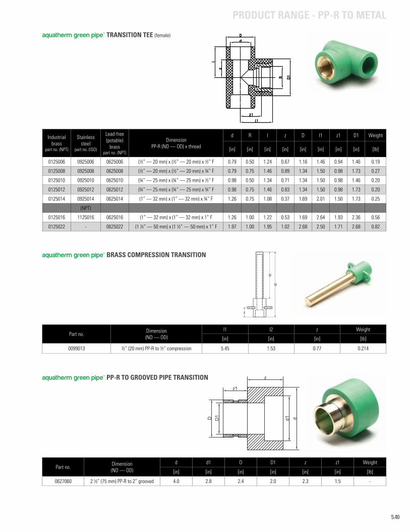
5.40
Industrial brass
part no. (NPT)
Stainless steel
part no. (ISO)
Lead-free (potable)
brasspart no. (NPT)
DimensionPP-R (ND — OD) x thread
d R l z D l1 z1 D1 Weight
[in] [in] [in] [in] [in] [in] [in] [in] [lb]
0125006 0925006 0625006 (½” — 20 mm) x (½” — 20 mm) x ½” F 0.79 0.50 1.24 0.67 1.16 1.46 0.94 1.46 0.19
0125008 0925008 0625008 (½” — 20 mm) x (½” — 20 mm) x ¾” F 0.79 0.75 1.46 0.89 1.34 1.50 0.98 1.73 0.27
0125010 0925010 0625010 (¾” — 25 mm) x (¾” — 25 mm) x ½” F 0.98 0.50 1.34 0.71 1.34 1.50 0.98 1.46 0.20
0125012 0925012 0625012 (¾” — 25 mm) x (¾” — 25 mm) x ¾” F 0.98 0.75 1.46 0.83 1.34 1.50 0.98 1.73 0.20
0125014 0925014 0625014 (1” — 32 mm) x (1” — 32 mm) x ¾” F 1.26 0.75 1.08 0.37 1.69 2.01 1.50 1.73 0.25
(NPT)
0125016 1125016 0625016 (1” — 32 mm) x (1” — 32 mm) x 1” F 1.26 1.00 1.22 0.53 1.69 2.64 1.93 2.36 0.56
0125022 - 0625022 (1 ½” — 50 mm) x (1 ½” — 50 mm) x 1” F 1.97 1.00 1.95 1.02 2.68 2.50 1.71 2.68 0.82
aquatherm green pipe® TRANSITION TEE (female)
PRODUCT RANGE - PP-R TO METAL
Part no. Dimension (ND — OD)
l1 l2 z Weight
[in] [in] [in] [lb]
0099013 ½” (20 mm) PP-R to ½” compression 5.45 1.53 0.77 0.214
aquatherm green pipe® BRASS COMPRESSION TRANSITION
aquatherm green pipe® PP-R TO GROOVED PIPE TRANSITION
Part no. Dimension(ND — OD)
d d1 D D1 z z1 Weight
[in] [in] [in] [in] [in] [in] [lb]
0627060 2 ½” (75 mm) PP-R to 2” grooved 4.0 2.8 2.4 2.0 2.3 1.5 -
dd1D
z
z1
D1
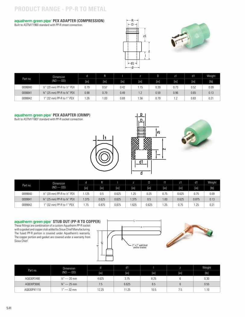
5.41
aquatherm green pipe® STUB OUT (PP-R TO COPPER)
aquatherm green pipe® PEX ADAPTER (CRIMP)Built to ASTM F1807 standard with PP-R socket connection.
aquatherm green pipe® PEX ADAPTER (COMPRESSION)Built to ASTM F1960 standard with PP-R street connection.
Part no. Dimension(ND — OD)
d R l z D l1 z1 d1 Weight
[in] [in] [in] [in] [in] [in] [in] [in] [lb]
0099840 ½” (20 mm) PP-R to ½” PEX 1.125 0.5 0.625 1.25 0.25 0.75 0.625 0.75 0.09
0099841 ¾” (25 mm) PP-R to ¾” PEX 1.375 0.625 0.625 1.375 0.5 1.00 0.625 0.875 0.13
0099842 1” (32 mm) PP-R to 1” PEX 1.75 0.875 0.875 1.625 0.625 1.25 0.75 1.25 0.21
Part no. Dimension(ND — OD)
d R l z D z1 d1 Weight
[in] [in] [in] [in] [in] [in] [in] [lb]
0098840 ½” (20 mm) PP-R to ½” PEX 0.79 0.57 0.42 1.15 0.39 0.73 0.52 0.09
0098841 ¾” (25 mm) PP-R to ¾” PEX 0.98 0.79 0.49 1.2 0.59 0.96 0.65 0.13
0098842 1” (32 mm) PP-R to 1” PEX 1.26 1.03 0.69 1.56 0.79 1.2 0.83 0.21
Part no. Dimension(ND — OD)
d d1 l z Weight
[in] [in] [in] [in] [lb]
AQ630P248E ½” — 20 mm 4.625 3.75 8.25 6 0.30
AQ630P368E ¾” — 25 mm 7.5 6.625 8.5 6 0.55
AQ630P41110 1” — 32 mm 12.25 11.25 10.5 7.5 1.10
These fittings are combination of a custom Aquatherm PP-R socket with a gasket and copper stub added by Sioux Chief Manufacturing. The fused PP-R portion is covered under Aquatherm’s warranty. The copper portion and gasket are covered under a warranty from Sioux Chief.
PRODUCT RANGE - PP-R TO METAL
2” x 2” wall/studanchor bracket
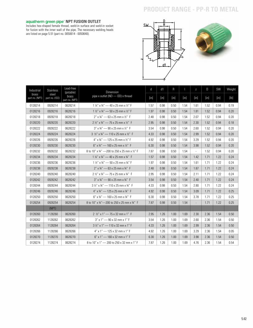
5.42
Industrial brass
part no. (NPT)
Stainless steel
part no. (ISO)
Lead-free (potable)
brasspart no. (NPT)
Dimensionpipe x outlet (ND — OD) x thread
d d1 R l z D SW Weight
[in] [in] [in] [in] [in] [in] [in] [lb]
0128214 0928214 0628214 1 ¼” x ¾” — 40 x 25 mm x ½” F 1.57 0.98 0.50 1.54 1.61 1.52 0.94 0.19
0128216 0928216 0628216 1 ½” x ¾” — 50 x 25 mm x ½” F 1.97 0.98 0.50 1.54 1.81 1.52 0.94 0.20
0128218 0928218 0628218 2” x ¾” — 63 x 25 mm x ½” F 2.48 0.98 0.50 1.54 2.07 1.52 0.94 0.20
0128220 0928220 0628220 2 ½” x ¾” — 75 x 25 mm x ½” F 2.95 0.98 0.50 1.54 2.30 1.52 0.94 0.18
0128222 0928222 0628222 3” x ¾” — 90 x 25 mm x ½” F 3.54 0.98 0.50 1.54 2.60 1.52 0.94 0.20
0128224 0928224 0628224 3 ½” x ¾” — 110 x 25 mm x ½” F 4.33 0.98 0.50 1.54 2.99 1.52 0.94 0.20
0128226 0928226 0628226 4” x ¾” — 125 x 25 mm x ½” F 4.92 0.98 0.50 1.54 3.29 1.52 0.94 0.20
0128230 0928230 0628230 6” x ¾” — 160 x 25 mm x ½” F 6.30 0.98 0.50 1.54 3.98 1.52 0.94 0.20
0128232 0928232 0628232 8 to 10” x ¾” —200 to 250 x 25 mm x ½” F 7.87 0.98 0.50 1.54 - 1.52 0.94 0.20
0128234 0928234 0628234 1 ¼” x ¾” — 40 x 25 mm x ¾” F 1.57 0.98 0.50 1.54 1.42 1.71 1.22 0.24
0128236 0928236 0628236 1 ½” x ¾” — 50 x 25 mm x ¾” F 1.97 0.98 0.50 1.54 1.61 1.71 1.22 0.24
0128238 0928238 0628238 2” x ¾” — 63 x 25 mm x ¾” F 2.48 0.98 0.50 1.54 1.87 1.71 1.22 0.24
0128240 0928240 0628240 2 ½” x ¾” — 75 x 25 mm x ¾” F 2.95 0.98 0.50 1.54 2.11 1.71 1.22 0.24
0128242 0928242 0628242 3” x ¾” — 90 x 25 mm x ¾” F 3.54 0.98 0.50 1.54 2.40 1.71 1.22 0.24
0128244 0928244 0628244 3 ½” x ¾” — 110 x 25 mm x ¾” F 4.33 0.98 0.50 1.54 2.80 1.71 1.22 0.24
0128246 0928246 0628246 4” x ¾” — 125 x 25 mm x ¾” F 4.92 0.98 0.50 1.54 3.09 1.71 1.22 0.25
0128250 0928250 0628250 6” x ¾” — 160 x 25 mm x ¾” F 6.30 0.98 0.50 1.54 3.78 1.71 1.22 0.25
0128254 0928254 0628254 8 to 10” x ¾”—200 to 250 x 25 mm x ¾” F 7.87 0.98 0.50 1.54 - 1.71 1.22 0.25
(NPT)
0128260 1128260 0628260 2 ½” x 1” — 75 x 32 mm x 1” F 2.95 1.26 1.00 1.69 2.30 2.36 1.54 0.50
0128262 1128262 0628262 3” x 1” — 90 x 32 mm x 1” F 3.54 1.26 1.00 1.69 2.60 2.36 1.54 0.50
0128264 1128264 0628264 3 ½” x 1” — 110 x 32 mm x 1” F 4.33 1.26 1.00 1.69 2.99 2.36 1.54 0.50
0128266 1128266 0628266 4” x 1” — 125 x 32 mm x 1” F 4.92 1.26 1.00 1.69 3.29 2.36 1.54 0.05
0128270 1128270 0628270 6” x 1” — 160 x 32 mm x 1” F 6.30 1.26 1.00 1.69 3.98 2.36 1.54 0.50
0128274 1128274 0628274 8 to 10” x 1” — 200 to 250 x 32 mm x 1” F 7.87 1.26 1.00 1.69 4.76 2.36 1.54 0.54
aquatherm green pipe® NPT FUSION OUTLET Includes hex-shaped female thread, weld-in surface and weld-in socket for fusion with the inner wall of the pipe. The necessary welding heads are listed on page 5.51 (part no. 0050614 - 0050640).
PRODUCT RANGE - PP-R TO METAL
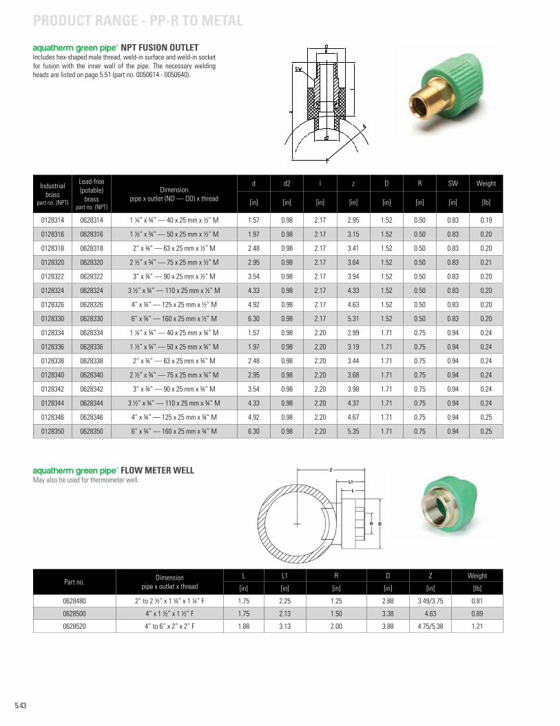
5.43
Industrial brass
part no. (NPT)
Lead-free (potable)
brasspart no. (NPT)
Dimension pipe x outlet (ND — OD) x thread
d d2 l z D R SW Weight
[in] [in] [in] [in] [in] [in] [in] [lb]
0128314 0628314 1 ¼” x ¾” — 40 x 25 mm x ½” M 1.57 0.98 2.17 2.95 1.52 0.50 0.83 0.19
0128316 0628316 1 ½” x ¾” — 50 x 25 mm x ½” M 1.97 0.98 2.17 3.15 1.52 0.50 0.83 0.20
0128318 0628318 2” x ¾” — 63 x 25 mm x ½” M 2.48 0.98 2.17 3.41 1.52 0.50 0.83 0.20
0128320 0628320 2 ½” x ¾” — 75 x 25 mm x ½” M 2.95 0.98 2.17 3.64 1.52 0.50 0.83 0.21
0128322 0628322 3” x ¾” — 90 x 25 mm x ½” M 3.54 0.98 2.17 3.94 1.52 0.50 0.83 0.20
0128324 0628324 3 ½” x ¾” — 110 x 25 mm x ½” M 4.33 0.98 2.17 4.33 1.52 0.50 0.83 0.20
0128326 0628326 4” x ¾” — 125 x 25 mm x ½” M 4.92 0.98 2.17 4.63 1.52 0.50 0.83 0.20
0128330 0628330 6” x ¾” — 160 x 25 mm x ½” M 6.30 0.98 2.17 5.31 1.52 0.50 0.83 0.20
0128334 0628334 1 ¼” x ¾” — 40 x 25 mm x ¾” M 1.57 0.98 2.20 2.99 1.71 0.75 0.94 0.24
0128336 0628336 1 ½” x ¾” — 50 x 25 mm x ¾” M 1.97 0.98 2.20 3.19 1.71 0.75 0.94 0.24
0128338 0628338 2” x ¾” — 63 x 25 mm x ¾” M 2.48 0.98 2.20 3.44 1.71 0.75 0.94 0.24
0128340 0628340 2 ½” x ¾” — 75 x 25 mm x ¾” M 2.95 0.98 2.20 3.68 1.71 0.75 0.94 0.24
0128342 0628342 3” x ¾” — 90 x 25 mm x ¾” M 3.54 0.98 2.20 3.98 1.71 0.75 0.94 0.24
0128344 0628344 3 ½” x ¾” — 110 x 25 mm x ¾” M 4.33 0.98 2.20 4.37 1.71 0.75 0.94 0.24
0128346 0628346 4” x ¾” — 125 x 25 mm x ¾” M 4.92 0.98 2.20 4.67 1.71 0.75 0.94 0.25
0128350 0628350 6” x ¾” — 160 x 25 mm x ¾” M 6.30 0.98 2.20 5.35 1.71 0.75 0.94 0.25
aquatherm green pipe® NPT FUSION OUTLETIncludes hex-shaped male thread, weld-in surface and weld-in socket for fusion with the inner wall of the pipe. The necessary welding heads are listed on page 5.51 (part no. 0050614 - 0050640).
PRODUCT RANGE - PP-R TO METAL
aquatherm green pipe® FLOW METER WELLMay also be used for thermometer well.
Part no. Dimension pipe x outlet x thread
L L1 R D Z Weight
[in] [in] [in] [in] [in] [lb]
0628480 2” to 2 ½” x 1 ¼” x 1 ¼” F 1.75 2.25 1.25 2.88 3.49/3.75 0.81
0628500 4” x 1 ½” x 1 ½” F 1.75 2.13 1.50 3.38 4.63 0.89
0628520 4” to 6” x 2” x 2” F 1.88 3.13 2.00 3.88 4.75/5.38 1.21
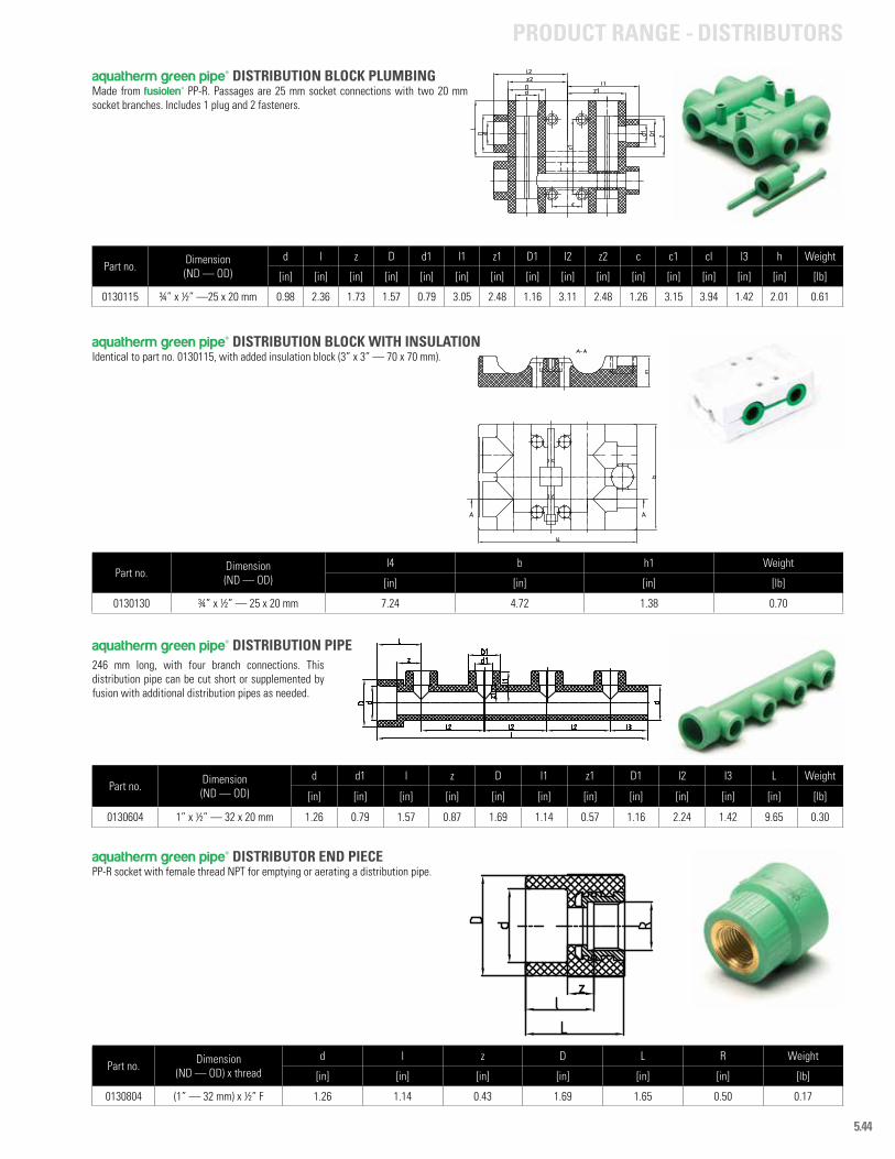
5.44
Part no. Dimension(ND — OD)
d l z D d1 l1 z1 D1 l2 z2 c c1 cl l3 h Weight
[in] [in] [in] [in] [in] [in] [in] [in] [in] [in] [in] [in] [in] [in] [in] [lb]
0130115 ¾” x ½” —25 x 20 mm 0.98 2.36 1.73 1.57 0.79 3.05 2.48 1.16 3.11 2.48 1.26 3.15 3.94 1.42 2.01 0.61
aquatherm green pipe® DISTRIBUTION BLOCK PLUMBINGMade from fusiolen® PP-R. Passages are 25 mm socket connections with two 20 mm socket branches. Includes 1 plug and 2 fasteners.
Part no. Dimension (ND — OD)
I4 b h1 Weight
[in] [in] [in] [lb]
0130130 ¾” x ½” — 25 x 20 mm 7.24 4.72 1.38 0.70
Part no. Dimension (ND — OD)
d d1 l z D l1 z1 D1 l2 I3 L Weight
[in] [in] [in] [in] [in] [in] [in] [in] [in] [in] [in] [lb]
0130604 1” x ½” — 32 x 20 mm 1.26 0.79 1.57 0.87 1.69 1.14 0.57 1.16 2.24 1.42 9.65 0.30
Part no. Dimension (ND — OD) x thread
d l z D L R Weight
[in] [in] [in] [in] [in] [in] [lb]
0130804 (1” — 32 mm) x ½” F 1.26 1.14 0.43 1.69 1.65 0.50 0.17
aquatherm green pipe® DISTRIBUTION BLOCK WITH INSULATIONIdentical to part no. 0130115, with added insulation block (3” x 3” — 70 x 70 mm).
aquatherm green pipe® DISTRIBUTION PIPE
aquatherm green pipe® DISTRIBUTOR END PIECEPP-R socket with female thread NPT for emptying or aerating a distribution pipe.
246 mm long, with four branch connections. This distribution pipe can be cut short or supplemented by fusion with additional distribution pipes as needed.
PRODUCT RANGE - DISTRIBUTORS
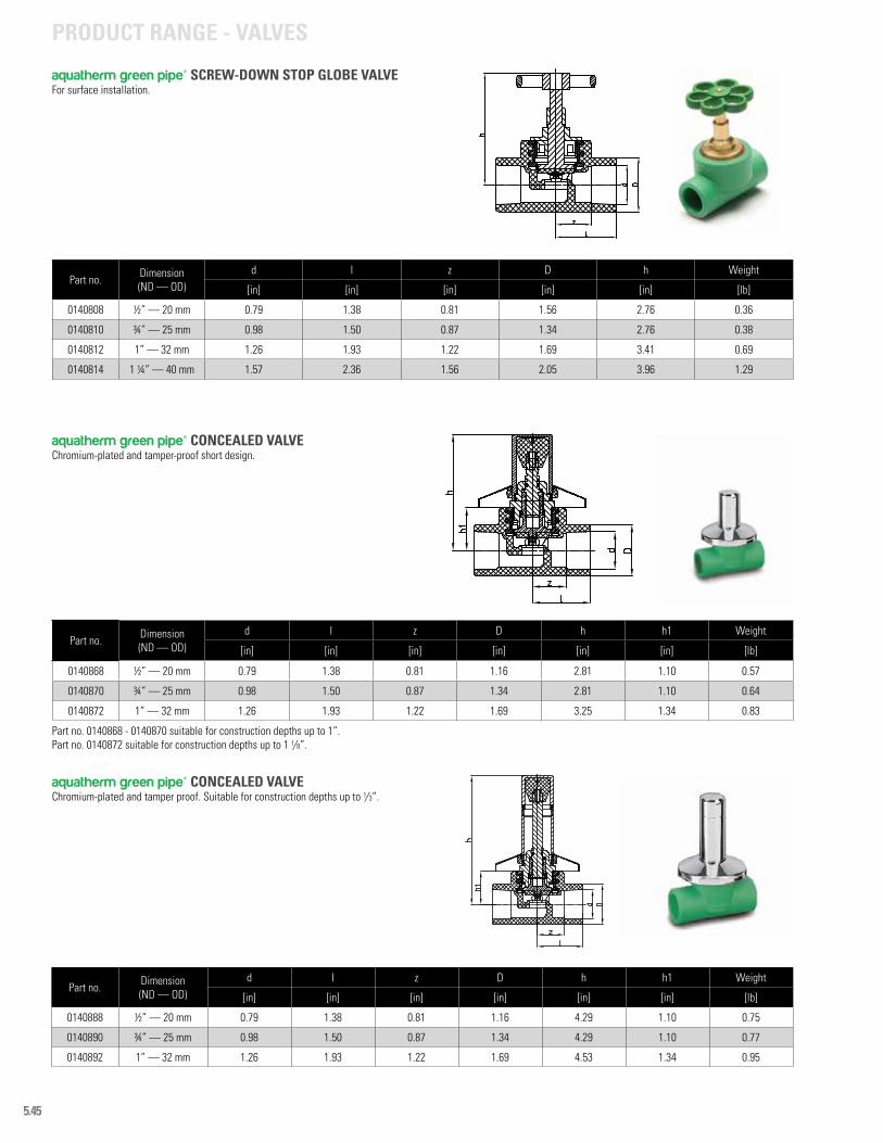
5.45
Part no. Dimension (ND — OD)
d l z D h Weight
[in] [in] [in] [in] [in] [lb]
0140808 ½” — 20 mm 0.79 1.38 0.81 1.56 2.76 0.36
0140810 ¾” — 25 mm 0.98 1.50 0.87 1.34 2.76 0.38
0140812 1” — 32 mm 1.26 1.93 1.22 1.69 3.41 0.69
0140814 1 ¼” — 40 mm 1.57 2.36 1.56 2.05 3.96 1.29
Part no. Dimension (ND — OD)
d l z D h h1 Weight
[in] [in] [in] [in] [in] [in] [lb]
0140868 ½” — 20 mm 0.79 1.38 0.81 1.16 2.81 1.10 0.57
0140870 ¾” — 25 mm 0.98 1.50 0.87 1.34 2.81 1.10 0.64
0140872 1” — 32 mm 1.26 1.93 1.22 1.69 3.25 1.34 0.83
aquatherm green pipe® SCREW-DOWN STOP GLOBE VALVEFor surface installation.
aquatherm green pipe® CONCEALED VALVEChromium-plated and tamper-proof short design.
Part no. 0140868 - 0140870 suitable for construction depths up to 1”.Part no. 0140872 suitable for construction depths up to 1 1/8”.
Part no. Dimension (ND — OD)
d l z D h h1 Weight
[in] [in] [in] [in] [in] [in] [lb]
0140888 ½” — 20 mm 0.79 1.38 0.81 1.16 4.29 1.10 0.75
0140890 ¾” — 25 mm 0.98 1.50 0.87 1.34 4.29 1.10 0.77
0140892 1” — 32 mm 1.26 1.93 1.22 1.69 4.53 1.34 0.95
aquatherm green pipe® CONCEALED VALVEChromium-plated and tamper proof. Suitable for construction depths up to 1/3”.
PRODUCT RANGE - VALVES
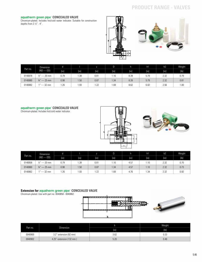
5.46
Part no. Dimension (ND — OD)
d l z D h h1 h2 Weight
[in] [in] [in] [in] [in] [in] [in] [lb]
0140858 ½” — 20 mm 0.79 1.38 0.81 1.16 4.57 1.10 2.32 0.70
0140860 ¾” — 25 mm 0.98 1.50 0.87 1.34 4.57 1.10 2.32 0.73
0140862 1” — 32 mm 1.26 1.93 1.22 1.69 4.76 1.34 2.32 0.92
aquatherm green pipe® CONCEALED VALVEChromium-plated. Includes hot/cold water indicator.
Part no. Dimension (ND — OD)
d l z D h h1 h2 Weight
[in] [in] [in] [in] [in] [in] [in] [lb]
0140878 ½” — 20 mm 0.79 1.38 0.81 1.16 8.39 5.79 2.32 0.79
0140880 ¾” — 25 mm 0.98 1.50 0.87 1.34 8.39 5.79 2.32 0.81
0140882 1” — 32 mm 1.26 1.93 1.22 1.69 8.62 6.02 2.56 1.00
Part no. Dimensionh Weight
[in] [lb]
0040900 3.2” extension (92 mm) 3.62 0.33
0040902 4.25” extension (132 mm ) 5.20 0.46
aquatherm green pipe® CONCEALED VALVEChromium-plated. Includes hot/cold water indicator. Suitable for construction depths from 2 1/8” - 4”.
Extension for aquatherm green pipe® CONCEALED VALVE Chromium-plated. Use with part no. 0040858 - 0040862.
PRODUCT RANGE - VALVES

5.47
Part no. Dimension PP-R (ND — OD) x thread
d l z D h D1 R Weight
[in] [in] [in] [in] [in] [in] [in] [lb]
0040908 ( ½” — 20 mm) x ¾” F 0.79 1.38 0.79 1.16 1.10 1.73 0.75 0.21
0040910 ( ¾” — 25 mm ) x ¾” F 0.98 1.50 0.87 1.34 1.10 1.73 0.75 0.22
0040912 ( 1” — 32 mm) x 1” F 1.26 1.93 1.22 1.69 1.34 2.05 1.00 0.32
0040914 ( 1 ¼” — 40 mm ) x 1 ¼” F 1.57 2.36 1.56 2.05 1.61 1.25 0.69
Part no. Dimension (ND — OD)
d l z D h Weight
[in] [in] [in] [in] [in] [lb]
141108 ½” — 20 mm 0.79 1.77 1.20 1.34 3.76 0.65
141110 ¾” — 25 mm 0.98 1.77 1.14 1.34 3.76 0.62
141112 1” — 32 mm 1.26 2.20 1.50 1.69 4.39 0.93
141114 1 ¼” — 40 mm 1.57 2.56 1.75 2.05 5.31 1.84
Part no. Dimension (ND — OD)
d l z D h Weight
[in] [in] [in] [in] [in] [lb]
0141208 ½” — 20 mm 0.79 1.77 1.20 1.34 3.76 0.65
0141210 ¾” — 25 mm 0.98 1.77 1.14 1.34 3.76 0.64
0141212 1” — 32 mm 1.26 2.20 1.50 1.69 4.39 0.95
0141214 1 ¼” — 40 mm 1.57 2.56 1.75 2.05 5.31 1.85
aquatherm green pipe® STOP VALVE BODY ISO
aquatherm green pipe® INCLINED VALVE without drain
aquatherm green pipe® INCLINED CHECK VALVE without drain
PRODUCT RANGE - VALVES
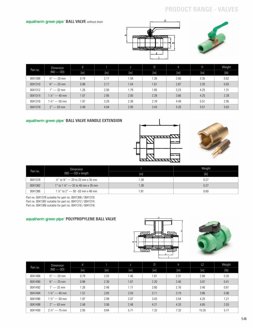
5.48
Part no. Dimension (ND — OD)
d l z D h l1 Weight
[in] [in] [in] [in] [in] [in] [lb]
0041308 ½” — 20 mm 0.79 2.17 1.59 1.26 2.60 3.35 0.62
0041310 ¾” — 25 mm 0.98 2.17 1.54 1.61 2.87 3.35 0.83
0041312 1” — 32 mm 1.26 2.50 1.79 1.85 3.23 4.25 1.31
0041314 1 ¼” — 40 mm 1.57 2.85 2.05 2.28 3.66 4.25 2.28
0041316 1 ½” — 50 mm 1.97 3.29 2.36 2.78 4.49 5.51 2.95
0041318 2” — 63 mm 2.48 4.04 2.95 3.43 5.20 5.51 5.63
Part no. Dimension (ND — OD) x length
l Weight
[in] [lb]
0041378 ½” to ¾” — 20 to 25 mm x 35 mm 1.38 0.27
0041382 1” to 1 ¼” — 32 to 40 mm x 35 mm 1.38 0.27
0041386 1 ½” to 2” — 50 - 63 mm x 46 mm 1.81 0.60
Part no. 0041378 suitable for part no. 0041308 / 0041310.Part no. 0041382 suitable for part no. 0041312 / 0041314.Part no. 0041386 suitable for part no. 0041316 / 0041318.
Part no. Dimension (ND — OD)
d l z D h L2 Weight
[in] [in] [in] [in] [in] [in] [lb]
0041488 ½” — 20 mm 0.79 2.03 1.46 1.81 2.01 2.68 0.26
0041490 ¾” — 25 mm 0.98 2.30 1.67 2.20 2.40 3.07 0.41
0041492 1” — 32 mm 1.26 2.48 1.77 2.60 2.76 3.46 0.61
0041494 1 ¼” — 40 mm 1.57 2.83 2.03 3.11 3.19 3.86 0.96
0041496 1 ½” — 50 mm 1.97 2.99 2.07 3.43 3.54 4.25 1.21
0041498 2” — 63 mm 2.48 3.56 2.48 4.21 4.33 4.65 2.03
0041400 2 ½” — 75 mm 2.95 9.84 5.71 7.32 7.32 15.35 5.77
aquatherm green pipe® BALL VALVE without drain
aquatherm green pipe® BALL VALVE HANDLE EXTENSION
aquatherm green pipe® POLYPROPYLENE BALL VALVE
PRODUCT RANGE - VALVES
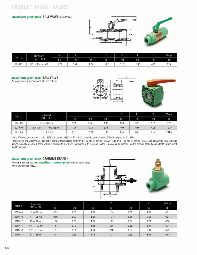
5.49
Part no. Dimension (ND — OD)
d l z D h1 h2 Weight
[in] [in] [in] [in] [in] [in] [lb]
0041602 3” — 90 mm 3.03 8.27 4.88 6.30 5.91 3.66 9.20
0041604a 3 ½” to 4” — 110 to 125 mm 3.70 10.24 5.71 7.09 6.50 4.06 12.25
0041607 6” — 160 mm 5.31 12.20 8.07 9.45 8.27 5.37 29.65
456
B
C
D
l
h1h2
z
123
B
C
D
D
d
a For a 4” connection, use part no. 0115526 and part no. 3315724. For a 3 ½” connection, use part no. 0115524 and part no. 3315724.Note: Screws and washers not included in delivery. Use hexagon screw M16 x 60 mm for part no. 41602/41604, M16 x 80 mm for part no. 41607, and flat washer M16. A flange gasket should be used with these valves in addition to the O-ring that comes with the valve, as the O-ring could be pressed into the grooves of the flange adapter which might lead to leakage.
Part no. Dimension (ND — OD)
d l z D z1 h Weight
[in] [in] [in] [in] [in] [in] [lb]
0041408 ½” — 20 mm 0.79 0.45 1.02 1.34 0.65 2.64 0.22
0041410 ¾” — 25 mm 0.98 0.39 1.02 1.34 0.65 2.64 0.21
0041412 1” — 32 mm 1.26 0.55 1.26 1.69 0.67 2.78 0.26
0041414 1 ¼” — 40 mm 1.57 0.47 1.28 2.05 0.65 3.01 0.31
0041416 1 ½” — 50 mm 1.97 0.61 1.54 2.68 0.67 3.30 0.45
0041418 2” — 63 mm 2.48 0.65 1.73 3.31 0.65 3.66 0.64
aquatherm green pipe® BALL VALVEPolypropylene construction with ISO bolt pattern.
aquatherm green pipe® DRAINING BRANCHWelded in-line for use with aquatherm green pipe valves or other cases where draining is needed.
PRODUCT RANGE - VALVES
Part no. Dimension (ND — OD)
d l z D z1 h l1 Weight
[in] [in] [in] [in] [in] [in] [in] [lb]
0078000 (1” — 32 mm) M/F 1.26 2.48 1.77 1.87 1.83 3.07 4.25 1.27
aquatherm green pipe® BALL VALVE (male/female)

5.50
Part no. Dimension Weight [lb]
0050104 ( 3/8” - 1 ¼” ) — ( 16 - 40 mm ) 1.31
AQUATHERM PIPE CUTTERFor use with Aquatherm PP-R only.
Part no. Dimension
0050195 -
AQUATHERM TEMPERATURE PROTECTIVE GLOVESFor use during fusion and changing welding heads.
AQUATHERM REPAIR SETFor closing pipe holes up to 0.4 in. Use with repair plug (part no. 0060600).
Part no. Dimension Weight [lb]
0050307 ¼” — 7 mm 0.37
0050311 7/16” — 11 mm 0.37
Part no. Dimension OD for each end Weight [lb]
0060600 7/16” x ¼” — 11 x 7 mm 0.02
aquatherm green pipe® REPAIR PLUGPP-R plug for closing pipe holes up to 0.4 in. Use with Aquatherm repair set (part no. 0050307 & 0050311).
AQUATHERM DRILL BITFor the mounting of weld-in fusion outlets.
Part no. Dimension Weight [lb]
0050940 ½” & ¾” — 20 & 25 mm(for pipes 1 ¼” - 6” — 40 - 160 mm) 0.31
0050941 ½” & ¾” — 20 & 25 mm(for pipes 6” - 10” — 160 - 250 mm) 0.35
0050942 1” — 32 mm 0.46
0050944 1 ¼” — 40 mm 0.63
0050946 1 ½” — 50 mm 0.70
0050948 2” — 63 mm 1.00
0050950a 2 ½” — 75 mm 3.12
0050952a 3” — 90 mm 3.56
0050954a 3 ½” — 110 mm 4.80
0050956a 4” — 125 mm 4.42
0050958a 6” — 160 mm 8.81
0050960a 8” — 200 mm -
a Must be used in fixed drilling machine. Morse taper shank.
PRODUCT RANGE - TOOLS
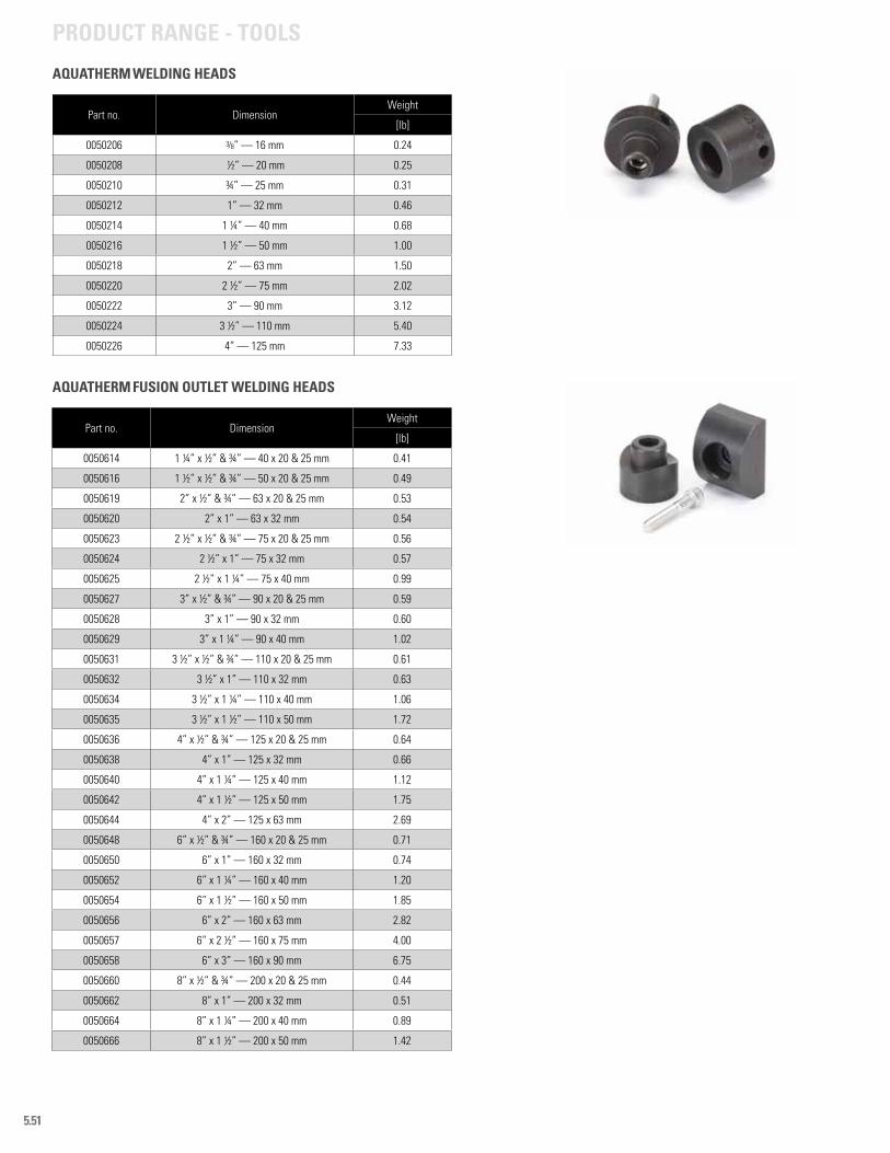
5.51
Part no. Dimension Weight
[lb]
0050614 1 ¼” x ½” & ¾” — 40 x 20 & 25 mm 0.41
0050616 1 ½” x ½” & ¾” — 50 x 20 & 25 mm 0.49
0050619 2” x ½” & ¾” — 63 x 20 & 25 mm 0.53
0050620 2” x 1” — 63 x 32 mm 0.54
0050623 2 ½” x ½” & ¾” — 75 x 20 & 25 mm 0.56
0050624 2 ½” x 1” — 75 x 32 mm 0.57
0050625 2 ½” x 1 ¼” — 75 x 40 mm 0.99
0050627 3” x ½” & ¾” — 90 x 20 & 25 mm 0.59
0050628 3” x 1” — 90 x 32 mm 0.60
0050629 3” x 1 ¼” — 90 x 40 mm 1.02
0050631 3 ½” x ½” & ¾” — 110 x 20 & 25 mm 0.61
0050632 3 ½” x 1” — 110 x 32 mm 0.63
0050634 3 ½” x 1 ¼” — 110 x 40 mm 1.06
0050635 3 ½” x 1 ½” — 110 x 50 mm 1.72
0050636 4” x ½” & ¾” — 125 x 20 & 25 mm 0.64
0050638 4” x 1” — 125 x 32 mm 0.66
0050640 4” x 1 ¼” — 125 x 40 mm 1.12
0050642 4” x 1 ½” — 125 x 50 mm 1.75
0050644 4” x 2” — 125 x 63 mm 2.69
0050648 6” x ½” & ¾” — 160 x 20 & 25 mm 0.71
0050650 6” x 1” — 160 x 32 mm 0.74
0050652 6” x 1 ¼” — 160 x 40 mm 1.20
0050654 6” x 1 ½” — 160 x 50 mm 1.85
0050656 6” x 2” — 160 x 63 mm 2.82
0050657 6” x 2 ½” — 160 x 75 mm 4.00
0050658 6” x 3” — 160 x 90 mm 6.75
0050660 8” x ½” & ¾” — 200 x 20 & 25 mm 0.44
0050662 8” x 1” — 200 x 32 mm 0.51
0050664 8” x 1 ¼” — 200 x 40 mm 0.89
0050666 8” x 1 ½” — 200 x 50 mm 1.42
AQUATHERM FUSION OUTLET WELDING HEADS
Part no. Dimension Weight
[lb]
0050206 3/8” — 16 mm 0.24
0050208 ½” — 20 mm 0.25
0050210 ¾” — 25 mm 0.31
0050212 1” — 32 mm 0.46
0050214 1 ¼” — 40 mm 0.68
0050216 1 ½” — 50 mm 1.00
0050218 2” — 63 mm 1.50
0050220 2 ½” — 75 mm 2.02
0050222 3” — 90 mm 3.12
0050224 3 ½” — 110 mm 5.40
0050226 4” — 125 mm 7.33
AQUATHERM WELDING HEADS
PRODUCT RANGE - TOOLS
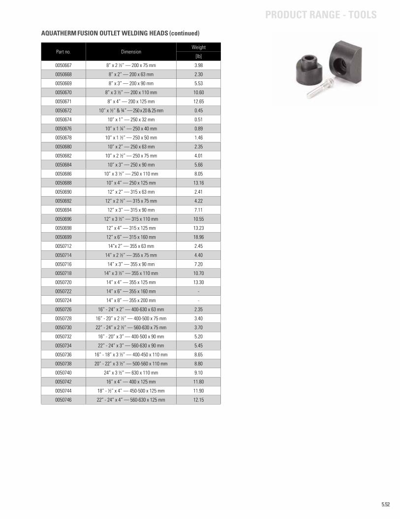
5.52
Part no. Dimension Weight
[lb]
0050667 8” x 2 ½” — 200 x 75 mm 3.98
0050668 8” x 2” — 200 x 63 mm 2.30
0050669 8” x 3” — 200 x 90 mm 5.53
0050670 8” x 3 ½” — 200 x 110 mm 10.60
0050671 8” x 4” — 200 x 125 mm 12.65
0050672 10” x ½” & ¾” — 250 x 20 & 25 mm 0.45
0050674 10” x 1” — 250 x 32 mm 0.51
0050676 10” x 1 ¼” — 250 x 40 mm 0.89
0050678 10” x 1 ½” — 250 x 50 mm 1.46
0050680 10” x 2” — 250 x 63 mm 2.35
0050682 10” x 2 ½” — 250 x 75 mm 4.01
0050684 10” x 3” — 250 x 90 mm 5.66
0050686 10” x 3 ½” — 250 x 110 mm 8.05
0050688 10” x 4” — 250 x 125 mm 13.16
0050690 12” x 2” — 315 x 63 mm 2.41
0050692 12” x 2 ½” — 315 x 75 mm 4.22
0050694 12” x 3” — 315 x 90 mm 7.11
0050696 12” x 3 ½” — 315 x 110 mm 10.55
0050698 12” x 4” — 315 x 125 mm 13.23
0050699 12” x 6” — 315 x 160 mm 18.96
0050712 14”x 2” — 355 x 63 mm 2.45
0050714 14” x 2 ½” — 355 x 75 mm 4.40
0050716 14” x 3” — 355 x 90 mm 7.20
0050718 14” x 3 ½” — 355 x 110 mm 10.70
0050720 14” x 4” — 355 x 125 mm 13.30
0050722 14” x 6” — 355 x 160 mm -
0050724 14” x 8” — 355 x 200 mm -
0050726 16” - 24” x 2” — 400-630 x 63 mm 2.35
0050728 16” - 20” x 2 ½” — 400-500 x 75 mm 3.40
0050730 22” - 24” x 2 ½” — 560-630 x 75 mm 3.70
0050732 16” - 20” x 3” — 400-500 x 90 mm 5.20
0050734 22” - 24” x 3” — 560-630 x 90 mm 5.45
0050736 16” - 18” x 3 ½” — 400-450 x 110 mm 8.65
0050738 20” - 22” x 3 ½” — 500-560 x 110 mm 8.80
0050740 24” x 3 ½” — 630 x 110 mm 9.10
0050742 16” x 4” — 400 x 125 mm 11.80
0050744 18” - ½” x 4” — 450-500 x 125 mm 11.90
0050746 22” - 24” x 4” — 560-630 x 125 mm 12.15
AQUATHERM FUSION OUTLET WELDING HEADS (continued)
PRODUCT RANGE - TOOLS
AQUATHERM GREEN PIPEA polypropylene pressure piping system designed for potable and food-grade applications. It is identified by its green color and joined using heat fusion. Hot water pipes have a multi-layer faser (MF) composition as well as dark green stripes, while cold water pipes have light blue stripes and no faser-composite layer.
BUTT WELDINGA heat fusion connection where the face of one pipe is fused directly to the face of another pipe. Fittings are sized to be even with the pipe walls and are joined the same way. This process is only used on sizes above 4 inches.
AQUATHERM BLUE PIPE®
Formerly know as Climatherm, aquatherm blue pipe® is a polypropylene pressure piping system designed for non-potable applications such as heating and cooling, chemical transport, compressed air, etc. aquatherm blue pipe® is blue, has a multi-layer faser (MF) composition and thick green stripes, and is also joined using heat fusion.
EXTRUSIONThe process by which Aquatherm’s pipes are manufactured. The fusiolen® material is shaped and pushed from the extrusion machine in three layers and cooled in long tanks, forming the uniquely designed Aquatherm pipes.
MULTI-LAYER FASER (MF)A patented mixture of fusiolen® PP-R and fiberglass, specially engineered to increase structural strength and reduce linear expansion.
FUSIOLEN PP-RThe basic material used in all of Aquatherm’s polypropylene piping systems. This resin is produced exclusively by Aquatherm using only the purest raw polypropylene.
FUSION OUTLETA special fitting designed to fuse directly onto the side of a pipe. These fittings were once called saddles but have been renamed to distinguish them from less reliable mechanical fittings.
HEAT FUSION (OR HEAT WELDING)The process of simultaneously heating two similar plastics and allowing them to cool together under pressure. This process forms a seamless bond between the materials.
AQUATHERM LILAC PIPEA special formulation of the Aquatherm piping systems engineered for use in rainwater and reclaimed water. This system is distinguished by the purple color of the pipe.
LINEAR (THERMAL) EXPANSIONThe growth in a pipe that occurs when hot water is run through the system. Contraction can also occur under cold temperatures.
MOLD INJECTIONThe process through which Aquatherm’s fittings are manufactured. Heated fusiolen® is pressed into molds and cooled under high pressure, creating strong fittings with no mechanical weaknesses.
POLYPROPYLENE RANDOM (PP-R)A unique formulation of the thermoplastic polymer used to create all the Aquatherm pipe and fittings. Random lengths of polypropylene molecules ensure chemical uniformity throughout the connection.
SOCKET FUSIONA heat fusion connection using welding heads and special fittings. The inside of the fitting is fused to the outside of the pipe, forming a quick and simple leak-proof connection. This process is only used on sizes from 4 inches and smaller.
TRANSITION, FLANGEA flange connection using a polypropylene flange, a steel flange ring, and a gasket that can be attached to a same-size flange of any other piping material.
TRANSITION, THREADEDA special fitting with a brass or stainless steel insert mold injected into the polypropylene. The insert is threaded for use with any other type of threaded connection.
WELDING HEADSTeflon-coated molds designed to match specific sizes of pipe and fittings. The welding heads are engineered for direct contact with the pipe and fittings and generally contain one male side and one female side in order to heat both sides of a connection at the same time.
WELDING IRONAn electronic heating device with a large, flat heating surface. This surface is designed to heat the welding heads to the proper welding temperature and should never be in direct contact with the material being welded.
WELDING JIGA portable clamping system that assists with moving the pipe and fitting during the fusion process.
GLOSSARY
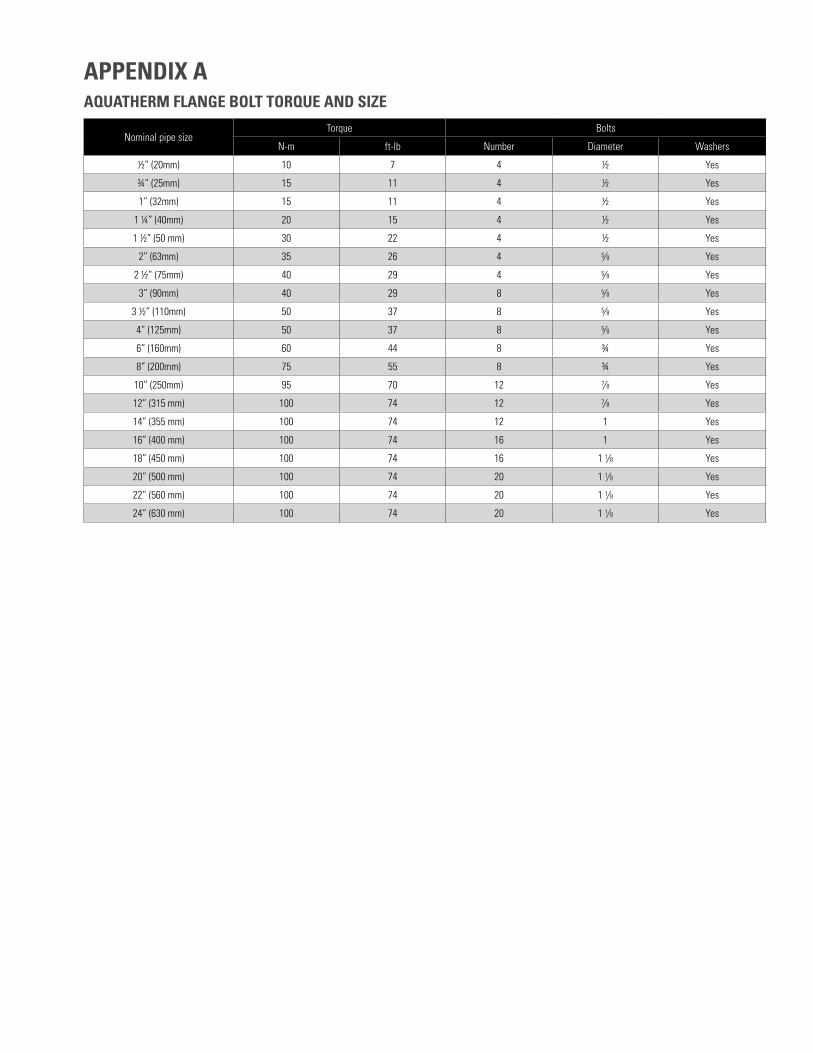
AQUATHERM FLANGE BOLT TORQUE AND SIZE
Nominal pipe sizeTorque Bolts
N-m ft-lb Number Diameter Washers
½” (20mm) 10 7 4 ½ Yes
¾” (25mm) 15 11 4 ½ Yes
1” (32mm) 15 11 4 ½ Yes
1 ¼” (40mm) 20 15 4 ½ Yes
1 ½” (50 mm) 30 22 4 ½ Yes
2” (63mm) 35 26 4 5/8 Yes
2 ½” (75mm) 40 29 4 5/8 Yes
3” (90mm) 40 29 8 5/8 Yes
3 ½” (110mm) 50 37 8 5/8 Yes
4” (125mm) 50 37 8 5/8 Yes
6” (160mm) 60 44 8 ¾ Yes
8” (200mm) 75 55 8 ¾ Yes
10” (250mm) 95 70 12 7/8 Yes
12” (315 mm) 100 74 12 7/8 Yes
14” (355 mm) 100 74 12 1 Yes
16” (400 mm) 100 74 16 1 Yes
18” (450 mm) 100 74 16 1 1/8 Yes
20” (500 mm) 100 74 20 1 1/8 Yes
22” (560 mm) 100 74 20 1 1/8 Yes
24” (630 mm) 100 74 20 1 1/8 Yes
APPENDIX A
Accessories 5.9
Applications 1.1 - 1.8
Aquatherm Blue Pipe 1.1, 1.5 - 1.6, 5.4 - 5.7
Aquatherm Green Pipe 1.1, 1.3 - 1.4, 5.1 - 5.3
Aquatherm Lilac Pipe 1.1, 1.8, 5.8
Chemicals 1.1, 3.7
Codes 2.1, 2.4 - 2.5, 3.6
Couplings 5.33 - 5.34
Ecology 1.10
Equivalent lengths 3.28 - 3.33
Multi-layer faser (MF) 1.7, 4.7
Fire stopping 3.8
Fittings 5.10 - 5.30
Flame spread 3.5
Flanges 5.31 - 5.32
Flow rates 3.9 - 3.27
Fusion 4.1 - 4.3
Hanger spacing 4.5 - 4.6
Impact 1.11, 2.3
LEED 1.10
Linear expansion 4.7 - 4.14
Mounting devices 5.9
Polypropylene 1.9 - 1.12
Pipe friction 3.9 - 3.33
Pump connections 3.8
Quality control 2.1
Smoke developed 3.5
Testing
– material testing 2.1 - 2.3
– pressure testing 4.20 - 4.21
Threaded connections 5.35 - 5.43
Thrust blocking 3.8
Transitions
– flanges 5.31 - 5.32
– threaded 5.33 - 5.43
UV protection 2.3, 3.2, 3.8, 5.3, 5.6 - 5.7
Valves 5.46 - 5.49
Warranty 1.12
INDEX