Embed Size (px)
Citation preview
1
2
These guides provide detailed training and education to help readers better understand harness and lighting concepts that are relevant to specific installations, as well as providing preventative maintenance techniques. Truck-Lite’s Lighting and Harness User’s Guides make for excellent training sources in a conveniently sized manual.
To request a printed copy of Truck-Lite literature, or to download an electronic copy, check out Truck-Lite’s website at www.truck-lite.com.
Truck-Lite User’s Guides
3
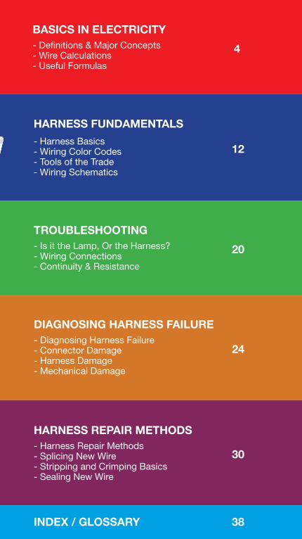
4BASICS IN ELECTRICITY- Definitions & Major Concepts- Wire Calculations- Useful Formulas
HARNESS FUNDAMENTALS- Harness Basics- Wiring Color Codes- Tools of the Trade- Wiring Schematics
12
TROUBLESHOOTING- Is it the Lamp, Or the Harness?- Wiring Connections- Continuity & Resistance
20
DIAGNOSING HARNESS FAILURE- Diagnosing Harness Failure- Connector Damage- Harness Damage- Mechanical Damage
24
HARNESS REPAIR METHODS- Harness Repair Methods- Splicing New Wire- Stripping and Crimping Basics- Sealing New Wire
30
INDEX / GLOSSARY 38
4
SECTION OBJECTIVES1. Definitions & Major Concepts2. Wire Calculations3. Useful Formulas
1. VOLT (Potential) VThe unit of measurement applied to the difference in electrical potential between two points; that is, the potential for electricity to flow.• Usually referenced from “ground.”• In water, voltage is roughly equivalent to the difference
in elevation from ground to a tank of water elevated above the ground; the electrical potential is similar to water pressure.
• The higher the potential (or elevation), the more force the water is able to exert and the more likely it is to flow.
2. AMP (Current) IThe unit of measurement applied to the flow of electricalcurrent through a conductor.• The amount of current (electrons) passing through
a conductor or passing a point in a wire or other electrical devices such as a light bulb.
1. Definitions
A comparison between electrical energy and waterflow will be useful in explaining and understandingelectrical concepts, but remember — water andelectricity generally should not be mixed.
BASICS IN ELECTRICITY

5
3. OHM (Resistance) RΩAs electrons flow through conductors, they meetopposition due to the collisions between the flowingelectrons and the electrons and atoms of the conductor.• This opposition to current flow, called resistance, is
measured in Ohms.
4. WATT (Power) P, W or PwThe unit of power applied to the rate at which energy is used.• Power is the amount of work that can be accomplished in a specified amount of time.• Work is simply defined as converting energy from one form to another, e.g., changing electrical energy into light energy.
5. WIRE SIZE (AWG)Because everything electrical depends on current flow, the conductors that carry the electricity are a critical part of any electrical system. The size of wires is important to allow the proper flow of electrons.• Resistance is opposition to current flow.• Wires that are too small in diameter will oppose current flow (this opposition is due to collisions of electrons which do not have enough room to pass).• These collisions convert electrical energy into heat (if enough of these collisions occur, the wire could overheat to the point of causing insulation melt-down and/or catch fire).• Wire sizes are measured according to the American Wire Gauge (AWG).
Definitions continued on next page ->
6
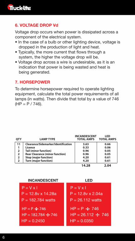
QTYINCANDESCENT LED
TOTAL AMPS TOTAL AMPSLAMP TYPE
Clearance/Sidemarker/IdentificationLicenceTail (minor function)Rear Clearance (minor function)Stop (major function)Turn (major function)
1112222
3.630.330.960.964.204.20
0.660.060.050.050.610.61
14.28 2.04
INCANDESCENT LED
P = V x IP = 12.8v x 14.28aP = 182.784 watts
HP = P 746
HP = 0.2450HP = 182.784 746
P = V x IP = 12.8v x 2.04aP = 26.112 watts
HP = P 746
HP = 0.0350HP = 26.112 746
6. VOLTAGE DROP VdVoltage drop occurs when power is dissipated across acomponent of the electrical system.• In the case of a bulb or other lighting device, voltage is
dropped in the production of light and heat.• Typically, the more current that flows through a
system, the higher the voltage drop will be.• Voltage drop across a wire is undesirable, as it is an
indication that power is being wasted and heat is being generated.
7. HORSEPOWERTo determine horsepower required to operate lightingequipment, calculate the total power requirements of alllamps (in watts). Then divide that total by a value of 746(HP = P / 746).

7
2. Wire Size Calculations
2.03.04.06.08.0
10.012.014.016.020.022.024.030.036.040.0
1.01.52.03.04.05.06.07.08.0
10.011.012.015.018.020.0
181818181818181818181818181616
181818181818181818161616161414
181818181818161616141414121212
181818181616161414121212121010
181818181614141412121212101010
1818181616141412121210101088
1818181614141212121010101088
181816161412121210101010888
18181614141212101010108888
1818161412121210101088886
10’24v
System12v
System 20’ 30’ 40’ 50’ 60’ 70’ 80’ 90’ 100’
TOTAL FOOTAGE OF WIRE FROM POWER SOURCETO THE MOST DISTANT ELECTRIC LAMP
AMPE
RAG
E RE
QU
IRED
* Values depict wire gauge
WIRE GAUGE REQUIREMENTS
Wire Size Calculations continued on next page ->
The length of wire in a circuit is a major contributingfactor to voltage drop. The table below may beused to determine adequate wire gauge sizesfor specific lengths of cable when the amperage(current) requirements are known.
• Everything electrical relies upon current flow.• The conductor that carries the electricity is a critical
part of the system.• Wire size is vital to allow the proper flow of electrons
(smaller diameter wire will oppose current flow).• Constricting the room for electrons to pass within the
wire causes collision of electrons, which generates heat inside the wire.
8
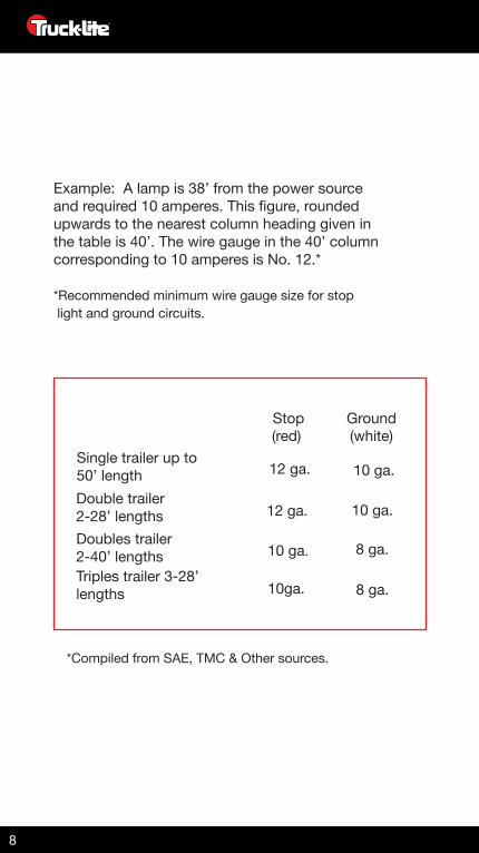
Example: A lamp is 38’ from the power sourceand required 10 amperes. This figure, roundedupwards to the nearest column heading given inthe table is 40’. The wire gauge in the 40’ columncorresponding to 10 amperes is No. 12.*
*Recommended minimum wire gauge size for stop light and ground circuits.
*Compiled from SAE, TMC & Other sources.
Stop Ground(red) (white)
Single trailer up to 50’ lengthDouble trailer2-28’ lengthsDoubles trailer 2-40’ lengthsTriples trailer 3-28’ lengths
12 ga.
12 ga.
10 ga.
10ga.
10 ga.
10 ga.
8 ga.
8 ga.
9
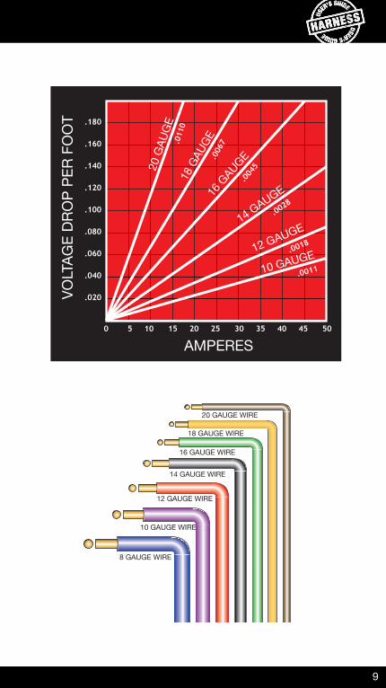
0 5 10 15 20 25 30 35 40 45 50
AMPERES
VOLT
AGE
DRO
P PE
R FO
OT .180
.160
.140
.120
.100
.080
.060
.040
.020
.011
0
.006
7
.004
5
.0028
.0018
.0011
20 G
AUG
E18
GAU
GE16
GAUGE
14 GAUGE
12 GAUGE
10 GAUGE
20 GAUGE WIRE
18 GAUGE WIRE
16 GAUGE WIRE
14 GAUGE WIRE
12 GAUGE WIRE
10 GAUGE WIRE
8 GAUGE WIRE
10
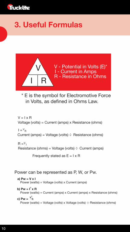
3. Useful Formulas
Power can be represented as P, W, or Pw.
V V - Potential in Volts (E)*
* E is the symbol for Electromotive Force in Volts, as defined in Ohms Law.
I - Current in AmpsR - Resistance in OhmsI R
V
V = I x RVoltage (volts) = Current (amps) x Resistance (ohms)
Current (amps) = Voltage (volts) Resistance (ohms)
Resistance (ohms) = Voltage (volts) Current (amps)
Frequently stated as E = I x R
I = R
VR = I
V2
2
a) Pw = V x I
b) Pw = I x R
Power (watts) = Voltage (volts) x Current (amps)
Power (watts) = Current (amps) x Current (amps) x Resistance (ohms)
Power (watts) = Voltage (volts) x Voltage (volts) Resistance (ohms)c) Pw = R

11
2b) Pw = I x R
V2c) Pw = R
a) Pw = V x IPw = 12 x 4Pw = 48w
Pw = 4 x 4 x 3Pw = 48w
Pw = 12 x 12 3Pw = 48w
12v
4a
3Ω
NOTES:
12
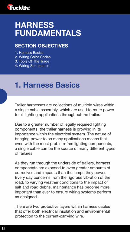
SECTION OBJECTIVES1. Harness Basics2. Wiring Color Codes3. Tools Of The Trade4. Wiring Schematics
1. Harness Basics
Trailer harnesses are collections of multiple wires within a single cable assembly, which are used to route power to all lighting applications throughout the trailer.
Due to a greater number of legally required lighting components, the trailer harness is growing in its importance within the electrical system. The nature of bringing power to so many applications means that even with the most problem-free lighting components, a single cable can be the source of many different types of failures.
As they run through the underside of trailers, harness components are exposed to even greater amounts of corrosives and impacts than the lamps they power. Every day concerns from the rigorous vibration of the road, to varying weather conditions to the impact of salt and road debris, maintenance has become more important than ever to ensure wiring systems perform as designed.
There are two protective layers within harness cables that offer both electrical insulation and environmental protection to the current-carrying wire.
HARNESSFUNDAMENTALS
13
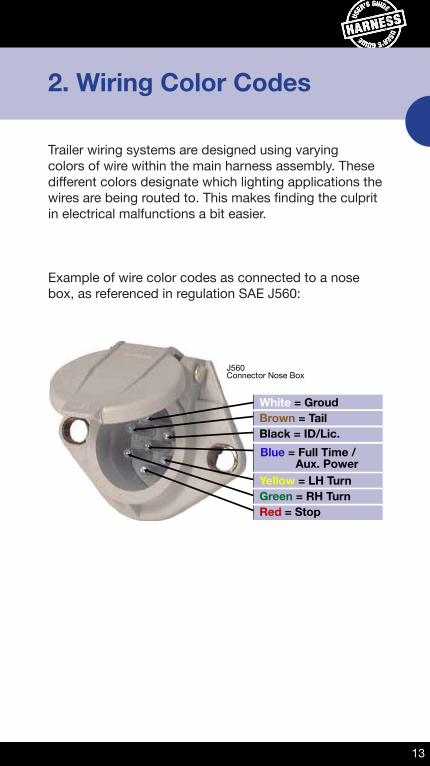
2. Wiring Color Codes
Trailer wiring systems are designed using varying colors of wire within the main harness assembly. These different colors designate which lighting applications the wires are being routed to. This makes finding the culprit in electrical malfunctions a bit easier.
Example of wire color codes as connected to a nose box, as referenced in regulation SAE J560:
J560Connector Nose Box
White = GroudBrown = TailBlack = ID/Lic.
Yellow = LH TurnGreen = RH TurnRed = Stop
Blue = Full Time / Aux. Power
14
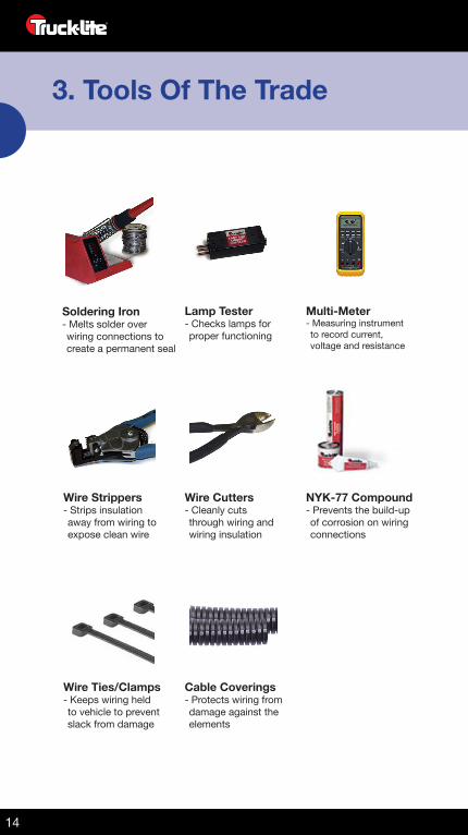
Lamp Tester- Checks lamps for proper functioning
Multi-Meter- Measuring instrument to record current, voltage and resistance
Wire Strippers- Strips insulation away from wiring to expose clean wire
Wire Cutters- Cleanly cuts through wiring and wiring insulation
NYK-77 Compound- Prevents the build-up of corrosion on wiring connections
Wire Ties/Clamps- Keeps wiring held to vehicle to prevent slack from damage
Cable Coverings- Protects wiring from damage against the elements
Soldering Iron- Melts solder over wiring connections to create a permanent seal
3. Tools Of The Trade
15
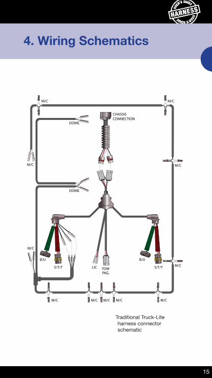
4. Wiring Schematics
M/C
M/C
M/C M/C
M/C
M/C
DOME
S/T/T S/T/T
B/UB/U
LIC TOWPKG.
DOME
CHASSISCONNECTION
M/C
M/C M/C M/C M/C
Traditional Truck-Lite harness connector schematic
16
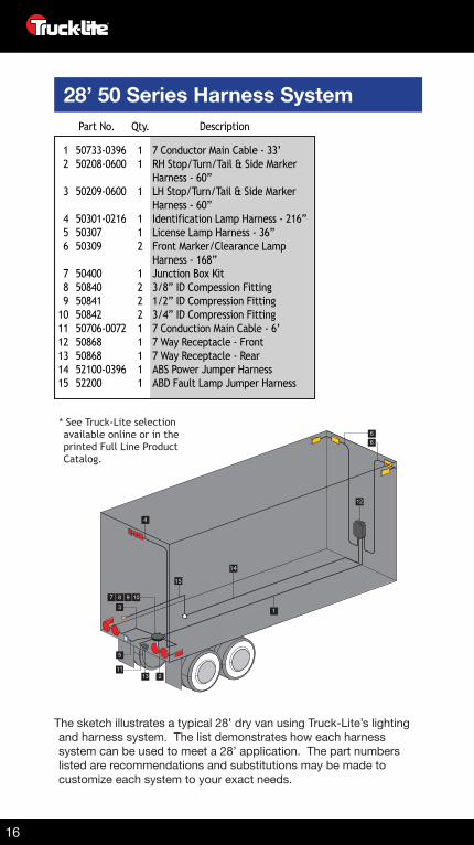
* See Truck-Lite selection available online or in the printed Full Line Product Catalog.
The sketch illustrates a typical 28’ dry van using Truck-Lite’s lighting and harness system. The list demonstrates how each harness system can be used to meet a 28’ application. The part numbers listed are recommendations and substitutions may be made to customize each system to your exact needs.
50733-039650208-0600
50209-0600
50301-02165030750309
5040050840508415084250706-0072508685086852100-039652200
12
3
456
789
101112131415
11
1
112
122211111
7 Conductor Main Cable - 33’RH Stop/Turn/Tail & Side MarkerHarness - 60”LH Stop/Turn/Tail & Side MarkerHarness - 60”Identification Lamp Harness - 216”License Lamp Harness - 36”Front Marker/Clearance LampHarness - 168”Junction Box Kit3/8” ID Compession Fitting1/2” ID Compression Fitting3/4” ID Compression Fitting7 Conduction Main Cable - 6’7 Way Receptacle - Front7 Way Receptacle - RearABS Power Jumper HarnessABD Fault Lamp Jumper Harness
Part No. Qty. Description
6
4
6
12
5
10987
3
1113 2
1
14
15
28’ 50 Series Harness System
17
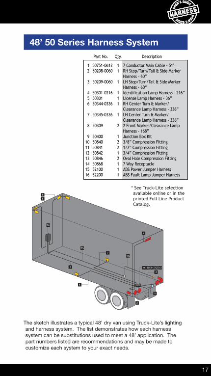
* See Truck-Lite selection available online or in the printed Full Line Product Catalog.
The sketch illustrates a typical 48’ dry van using Truck-Lite’s lighting and harness system. The list demonstrates how each harness system can be substitutions used to meet a 48’ application. The part numbers listed are recommendations and may be made to customize each system to your exact needs.
50751-061250208-0060
50209-0060
50301-02165030150344-0336
50345-0336
50309
5040050840508415084250846508685210052200
12
3
456
7
8
910111213141516
11
1
111
1
2
12212111
7 Conductor Main Cable - 51’RH Stop/Turn/Tail & Side MarkerHarness - 60”LH Stop/Turn/Tail & Side MarkerHarness - 60“Identification Lamp Harness - 216”License Lamp Harness - 36”RH Center Turn & Marker/Clearance Lamp Harness - 336”LH Center Turn & Marker/Clearance Lamp Harness - 336”2 Front Marker/Clearance LampHarness - 168”Junction Box Kit3/8” Compression Fitting1/2” Compression Fitting3/4” Compression FittingOval Hole Compression Fitting7 Way ReceptacleABS Power Jumper HarnessABS Fault Lamp Jumper Harness
Part No. Qty. Description
8
4
8
14
5
11109
3
2
1
7
6
16
15
1312
48’ 50 Series Harness System

18
28’ Van Trailer Harness System
48’/53’ Van Trailer Harness System
88703 420889118830188303883075030988100 12052200
88703 420889318836888373883075037788100 12052203
12345678
11121211
7 Conductor Main Cable - 35’Rear Sill HarnessUpper ID Harness, 192”Rear Marker Lamp Harness, 24”License Lamp Harness, 36”Front M/C Harness, 168”ABS Power Jumper Harness. 120”ABS Fault Lamp Jumper Harness
Part No. LED Part No. Qty. Description
887038891188301883038830750309513555135688100 12052200
887038893188368883738830750377513435134288100 12052203
123456789
10
1112121111
7 Conductor Main Cable - 60’Rear Sill HarnessUpper ID Harness, 192”Rear Marker Lamp Harness, 24”License Lamp Harness, 36”Front M/C Harness, 168”Mid Turn Harness, Left Side, 420“Mid Turn Harness, Right Side, 420”ABS Power Jumper Harness. 120”ABS Fault Lamp Jumper Harness
Part No. LED Part No. Qty. Description
6
4
6
1
42
5
3
7
8
109
6
4
6
1
42
5
3
8 7
INTERNAL GROUND
INTERNAL GROUND
88703 6248891188300883035135551356883038030988100 12052200
88703 6248893188367883735134351342883035037788100 12052203
123456789
10
1112121111
7 Conductor Main Cable - 52’Rear Sill HarnessLower ID Harness, 60”Rear Marker Lamp Harness, 24”Mid Turn Harness, Left Side, 420“Mid Turn Harness, Right Side, 420”License Lamp HarnessFront M/C HarnessABS Power Jumper Harness. 120”ABS Fault Lamp Jumper Harness
Part No. LED Part No. Qty. Description
41
42
7
3
5
6
8
8
10 9
INTERNAL GROUND
19
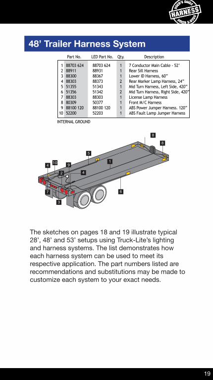
48’ Trailer Harness System
88703 6248891188300883035135551356883038030988100 12052200
88703 6248893188367883735134351342883035037788100 12052203
123456789
10
1112121111
7 Conductor Main Cable - 52’Rear Sill HarnessLower ID Harness, 60”Rear Marker Lamp Harness, 24”Mid Turn Harness, Left Side, 420“Mid Turn Harness, Right Side, 420”License Lamp HarnessFront M/C HarnessABS Power Jumper Harness. 120”ABS Fault Lamp Jumper Harness
Part No. LED Part No. Qty. Description
41
42
7
3
5
6
8
8
10 9
INTERNAL GROUND
The sketches on pages 18 and 19 illustrate typical 28’, 48’ and 53’ setups using Truck-Lite’s lighting and harness systems. The list demonstrates how each harness system can be used to meet its respective application. The part numbers listed are recommendations and substitutions may be made to customize each system to your exact needs.
20
28’ Van Trailer Harness System
SECTION OBJECTIVES1. Is It The Lamp, Or The Harness?2. Wiring Connections 3. Continuity & Resistance
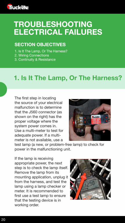
1. Is It The Lamp, Or The Harness?
The first step in locating the source of your electrical malfunction is to determine that the J560 connector (as shown on the right) has the proper voltage where the system power comes in. Use a multi-meter to test for adequate power. If a multi-meter is not available, use a test lamp (a new, or problem-free lamp) to check for power in the malfunctioning unit.
If the lamp is receiving appropriate power, the next step is to check the lamp itself. Remove the lamp from its mounting application, unplug it from the harness, and test the lamp using a lamp checker or meter. It is recommended to first use a test lamp to ensure that the testing device is in working order.
TROUBLESHOOTINGELECTRICAL FAILURES
21
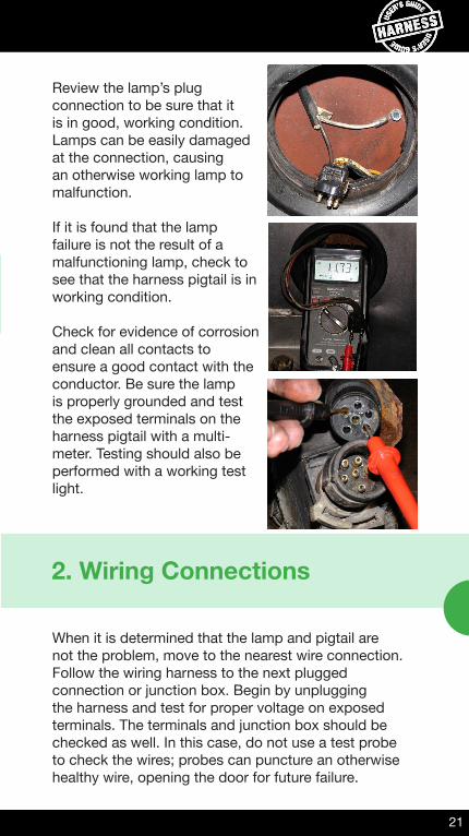
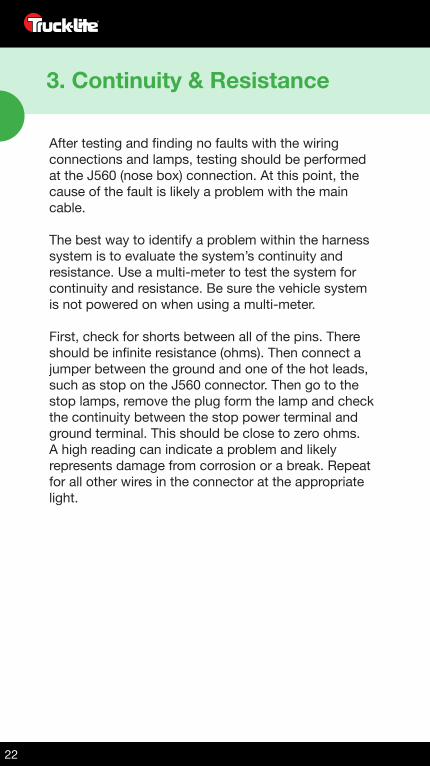
Review the lamp’s plug connection to be sure that it is in good, working condition. Lamps can be easily damaged at the connection, causing an otherwise working lamp to malfunction.
If it is found that the lamp failure is not the result of a malfunctioning lamp, check to see that the harness pigtail is in working condition.
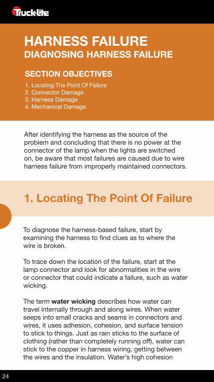
Check for evidence of corrosion and clean all contacts to ensure a good contact with the conductor. Be sure the lamp is properly grounded and test the exposed terminals on the harness pigtail with a multi-meter. Testing should also be performed with a working test light.
2. Wiring Connections
When it is determined that the lamp and pigtail are not the problem, move to the nearest wire connection. Follow the wiring harness to the next plugged connection or junction box. Begin by unplugging the harness and test for proper voltage on exposed terminals. The terminals and junction box should be checked as well. In this case, do not use a test probe to check the wires; probes can puncture an otherwise healthy wire, opening the door for future failure.
22
28’ Van Trailer Harness System
After testing and finding no faults with the wiring connections and lamps, testing should be performed at the J560 (nose box) connection. At this point, the cause of the fault is likely a problem with the main cable.
The best way to identify a problem within the harness system is to evaluate the system’s continuity and resistance. Use a multi-meter to test the system for continuity and resistance. Be sure the vehicle system is not powered on when using a multi-meter.
First, check for shorts between all of the pins. There should be infinite resistance (ohms). Then connect a jumper between the ground and one of the hot leads, such as stop on the J560 connector. Then go to the stop lamps, remove the plug form the lamp and check the continuity between the stop power terminal and ground terminal. This should be close to zero ohms. A high reading can indicate a problem and likely represents damage from corrosion or a break. Repeat for all other wires in the connector at the appropriate light.
3. Continuity & Resistance

23
NOTES:
24
28’ Van Trailer Harness System
SECTION OBJECTIVES1. Locating The Point Of Failure2. Connector Damage 3. Harness Damage4. Mechanical Damage
1. Locating The Point Of Failure
To diagnose the harness-based failure, start by examining the harness to find clues as to where the wire is broken.
To trace down the location of the failure, start at the lamp connector and look for abnormalities in the wire or connector that could indicate a failure, such as water wicking.
The term water wicking describes how water can travel internally through and along wires. When water seeps into small cracks and seams in connectors and wires, it uses adhesion, cohesion, and surface tension to stick to things. Just as rain sticks to the surface of clothing (rather than completely running off), water can stick to the copper in harness wiring, getting between the wires and the insulation. Water’s high cohesion
After identifying the harness as the source of the problem and concluding that there is no power at the connector of the lamp when the lights are switched on, be aware that most failures are caused due to wire harness failure from improperly maintained connectors.
HARNESS FAILUREDIAGNOSING HARNESS FAILURE
25
1. Locating The Point Of Failure
properties cause it to bead up and, through surface tension, it will stick to itself—as shown on a newly waxed car. Water that gets pulled into the small spaces in wiring, between the wire and insulation, drags along more water because it sticks to itself.
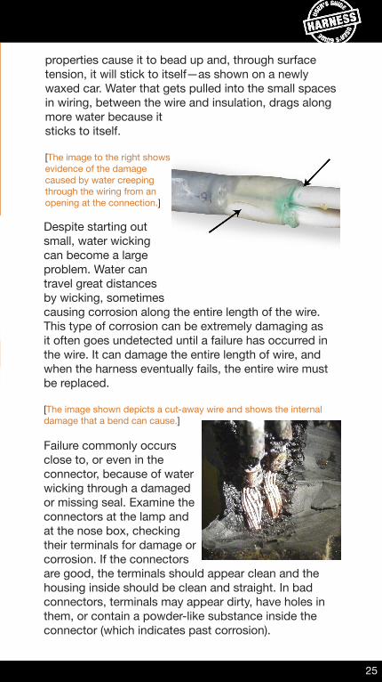
[The image to the right shows evidence of the damage caused by water creeping through the wiring from an opening at the connection.]
Despite starting out small, water wicking can become a large problem. Water can travel great distances by wicking, sometimes causing corrosion along the entire length of the wire. This type of corrosion can be extremely damaging as it often goes undetected until a failure has occurred in the wire. It can damage the entire length of wire, and when the harness eventually fails, the entire wire must be replaced.
[The image shown depicts a cut-away wire and shows the internal damage that a bend can cause.]
Failure commonly occurs close to, or even in the connector, because of water wicking through a damaged or missing seal. Examine the connectors at the lamp and at the nose box, checking their terminals for damage or corrosion. If the connectors are good, the terminals should appear clean and the housing inside should be clean and straight. In bad connectors, terminals may appear dirty, have holes in them, or contain a powder-like substance inside the connector (which indicates past corrosion).
26
28’ Van Trailer Harness System
SECTION OBJECTIVES1. Locating the Point of Failure2. Connector Damage 3. Harness Damage4. Mechanical Damage
2. Connector Damage
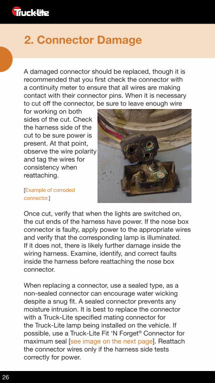
A damaged connector should be replaced, though it is recommended that you first check the connector with a continuity meter to ensure that all wires are making contact with their connector pins. When it is necessary to cut off the connector, be sure to leave enough wire for working on both sides of the cut. Check the harness side of the cut to be sure power is present. At that point, observe the wire polarity and tag the wires for consistency when reattaching.
[Example of corroded connector.]
Once cut, verify that when the lights are switched on, the cut ends of the harness have power. If the nose box connector is faulty, apply power to the appropriate wires and verify that the corresponding lamp is illuminated. If it does not, there is likely further damage inside the wiring harness. Examine, identify, and correct faults inside the harness before reattaching the nose box connector.
When replacing a connector, use a sealed type, as a non-sealed connector can encourage water wicking despite a snug fit. A sealed connector prevents any moisture intrusion. It is best to replace the connector with a Truck-Lite specified mating connector for the Truck-Lite lamp being installed on the vehicle. If possible, use a Truck-Lite Fit ‘N Forget® Connector for maximum seal [see image on the next page]. Reattach the connector wires only if the harness side tests correctly for power.
27
2. Connector Damage
3. Harness Damage
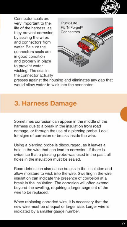
Connector seals are very important to the life of the harness, as they prevent corrosion by sealing the wires and connectors from water. Be sure the connectors seals are in good condition and properly in place to prevent water wicking. The seal in the connector actually presses against the housing and eliminates any gap that would allow water to wick into the connector.
Truck-LiteFit ‘N Forget®
Connectors
Sometimes corrosion can appear in the middle of the harness due to a break in the insulation from road damage, or through the use of a piercing probe. Look for signs of corrosion or breaks inside the wire.
Using a piercing probe is discouraged, as it leaves a hole in the wire that can lead to corrosion. If there is evidence that a piercing probe was used in the past, all holes in the insulation must be sealed.
Road debris can also cause breaks in the insulation and allow moisture to wick into the wire. Swelling in the wire insulation can indicate the presence of corrosion at a break in the insulation. The corrosion will often extend beyond the swelling, requiring a larger segment of the wire to be replaced.
When replacing corroded wire, it is necessary that the new wire must be of equal or larger size. Larger wire is indicated by a smaller gauge number.
28
28’ Van Trailer Harness System
SECTION OBJECTIVES1. Locating the Point of Failure2. Connector Damage 3. Harness Damage4. Mechanical Damage
HARNESS FAILURE4. Mechanical Damage
Stresses can easily damage a wire, as its design was meant to carry electricity, with little emphasis on mechanical strength. Weak spots due to corrosion, or mechanical stress can cause the wire to break without breaking the actual insulation, as the insulation is usually more resilient than the wire it protects. This type of break can be a very difficult failure to detect and repair; often, the entire length of wire must be replaced when the break cannot be found.
Wire tension can also cause a connector or wire to fail. If a wire is cut just long enough to reach the lamp, it can fail from an impact, from road debris, or from thermal expansion. Thermal expansion can cause the wires to shorten at cold temperatures, making them tight. This tightening may pull the wire out of the connector or cause internal breaks. Look for places where the wire appears to have little or no slack. Sharp bends in the wire can indicate an internal break as well.
Repeated flexing will stress the wire and sometimes cause it to break. To avoid this, connectors and splices should be restrained to prevent damage from excessive motion during vehicle movement. Often, failure locations can be found by moving the suspect wires and looking for intermittent operation when they change position.
Finally, look for any sharp bends in the wire, or the appearance of a wire kink. These may appear at the secured ends of excessively loose wire that can move a lot during vehicle motion. Remove the faulty segment and restrain the wire splices to prevent excessive motion and future internal breaks. For long wire runs (50 ft. and greater), the effects of thermal expansion can make the wire expand in hot weather or retract — sometimes up to several inches shorter — in cold weather.

29
HARNESS FAILURE NOTES:

30
28’ Van Trailer Harness System
SECTION OBJECTIVES1. General Repair Methods2. Splicing New Wire 3. Stripping & Crimping Basics4. Sealing New Wire
1. General Repair Methods
When cutting out the damaged portion of a wire, examine the cut ends of the remaining wire to be sure there is no corrosion present. If there is corrosion present, additional wire must be removed to ensure that the repair will not fail from the corrosion that is already present.
The cut and stripped wires should be clean and bright. If the wire is dull or dirty, it can be cleaned with steel wool or fine sandpaper to ensure a good electrical contact. If the internal wire is dark, this often indicates signs of corrosion or moisture, and it should be cut further back until clean, bright wire is exposed. It is best to remove and replace damaged or corroded wires, rather than perform repeated repairs.
REPAIRHARNESS REPAIR METHODS
31
2. Splicing New Wire
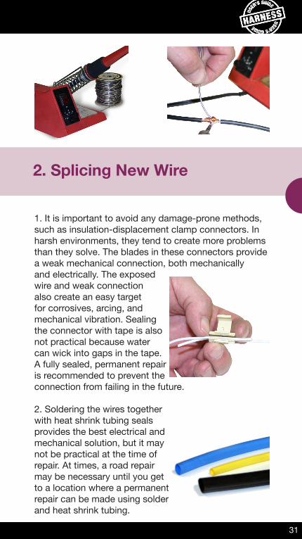
1. It is important to avoid any damage-prone methods, such as insulation-displacement clamp connectors. In harsh environments, they tend to create more problems than they solve. The blades in these connectors provide a weak mechanical connection, both mechanically and electrically. The exposed wire and weak connection also create an easy target for corrosives, arcing, and mechanical vibration. Sealing the connector with tape is also not practical because water can wick into gaps in the tape. A fully sealed, permanent repair is recommended to prevent the connection from failing in the future.
2. Soldering the wires together with heat shrink tubing seals provides the best electrical and mechanical solution, but it may not be practical at the time of repair. At times, a road repair may be necessary until you get to a location where a permanent repair can be made using solder and heat shrink tubing.
32
3. Stripping & Crimping Basics
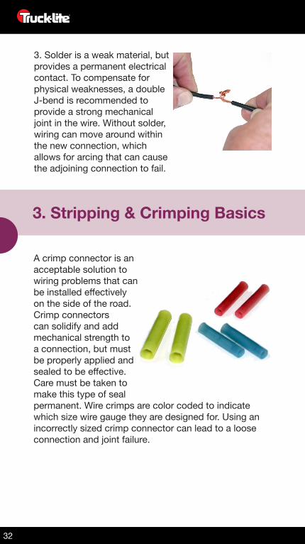
3. Solder is a weak material, but provides a permanent electrical contact. To compensate for physical weaknesses, a double J-bend is recommended to provide a strong mechanical joint in the wire. Without solder, wiring can move around within the new connection, which allows for arcing that can cause the adjoining connection to fail.
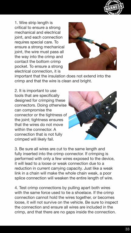
A crimp connector is an acceptable solution to wiring problems that can be installed effectively on the side of the road. Crimp connectors can solidify and add mechanical strength to a connection, but must be properly applied and sealed to be effective. Care must be taken to make this type of seal permanent. Wire crimps are color coded to indicate which size wire gauge they are designed for. Using an incorrectly sized crimp connector can lead to a loose connection and joint failure.
33
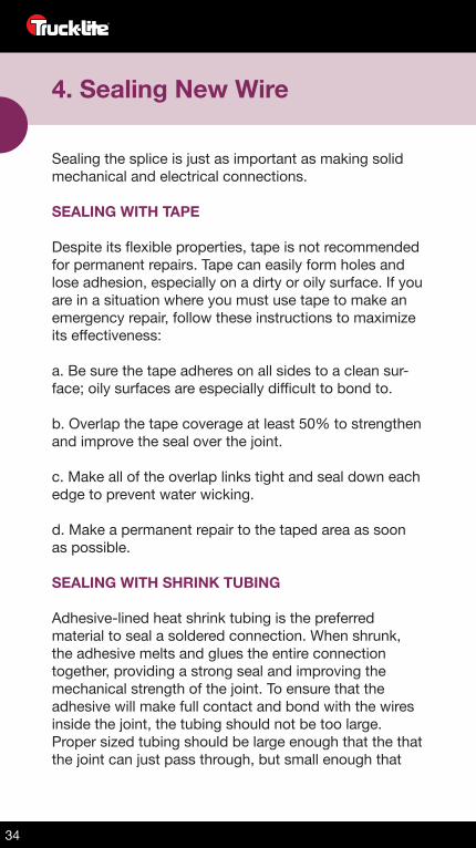
1. Wire strip length is critical to ensure a strong mechanical and electrical joint, and each connection requires special care. To ensure a strong mechanical joint, the wire must pass all the way into the crimp and contact the bottom crimp pocket. To ensure a strong electrical connection, it is important that the insulation does not extend into the crimp and that the wire is clean and bright.
2. It is important to use tools that are specifically designed for crimping these connectors. Doing otherwise can compromise the connector or the tightness of the joint; tightness ensures that the wires do not move within the connector. A connection that is not fully crimped will likely fail.
3. Be sure all wires are cut to the same length and fully inserted into the crimp connector. If crimping is performed with only a few wires exposed to the device, it will lead to a loose or weak connection due to a reduction in current carrying capacity. Just like a weak link in a chain will make the whole chain weak, a poor splice connection will weaken the entire length of wire.
4. Test crimp connections by pulling apart both wires with the same force used to tie a shoelace. If the crimp connection cannot hold the wires together, or becomes loose, it will not survive on the vehicle. Be sure to inspect the connection and ensure all wires are included in the crimp, and that there are no gaps inside the connection.
34
4. Sealing New Wire
Sealing the splice is just as important as making solid mechanical and electrical connections.
SEALING WITH TAPE
Despite its flexible properties, tape is not recommended for permanent repairs. Tape can easily form holes and lose adhesion, especially on a dirty or oily surface. If you are in a situation where you must use tape to make an emergency repair, follow these instructions to maximize its effectiveness:
a. Be sure the tape adheres on all sides to a clean sur-face; oily surfaces are especially difficult to bond to.
b. Overlap the tape coverage at least 50% to strengthen and improve the seal over the joint.
c. Make all of the overlap links tight and seal down each edge to prevent water wicking.
d. Make a permanent repair to the taped area as soon as possible.
SEALING WITH SHRINK TUBING
Adhesive-lined heat shrink tubing is the preferred material to seal a soldered connection. When shrunk, the adhesive melts and glues the entire connection together, providing a strong seal and improving the mechanical strength of the joint. To ensure that the adhesive will make full contact and bond with the wires inside the joint, the tubing should not be too large. Proper sized tubing should be large enough that the that the joint can just pass through, but small enough that
35
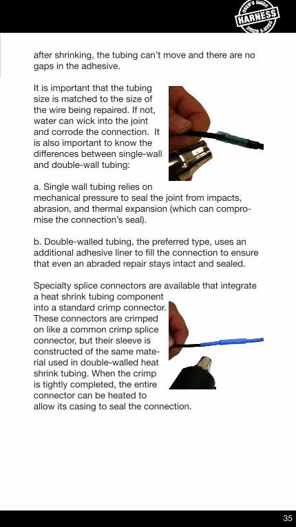
after shrinking, the tubing can’t move and there are no gaps in the adhesive.
It is important that the tubing size is matched to the size of the wire being repaired. If not, water can wick into the joint and corrode the connection. It is also important to know the differences between single-wall and double-wall tubing:
a. Single wall tubing relies on mechanical pressure to seal the joint from impacts, abrasion, and thermal expansion (which can compro-mise the connection’s seal).
b. Double-walled tubing, the preferred type, uses an additional adhesive liner to fill the connection to ensure that even an abraded repair stays intact and sealed.
Specialty splice connectors are available that integrate a heat shrink tubing component into a standard crimp connector. These connectors are crimped on like a common crimp splice connector, but their sleeve is constructed of the same mate-rial used in double-walled heat shrink tubing. When the crimp is tightly completed, the entire connector can be heated to allow its casing to seal the connection.
36
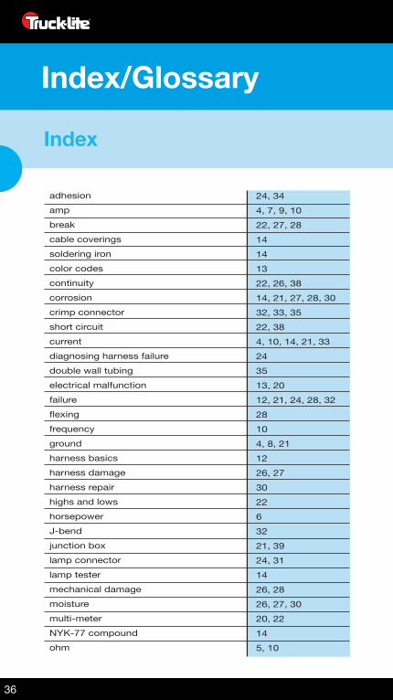
Index/Glossary
Index
adhesionampbreakcable coveringssoldering ironcolor codescontinuitycorrosioncrimp connectorshort circuitcurrentdiagnosing harness failuredouble wall tubingelectrical malfunctionfailureflexingfrequencygroundharness basicsharness damageharness repairhighs and lowshorsepowerJ-bendjunction boxlamp connectorlamp testermechanical damagemoisturemulti-meterNYK-77 compoundohm
24, 344, 7, 9, 1022, 27, 2814141322, 26, 3814, 21, 27, 28, 3032, 33, 3522, 38 4, 10, 14, 21, 33243513, 2012, 21, 24, 28, 322810 4, 8, 211226, 27302263221, 3924, 311426, 2826, 27, 3020, 22145, 10
37
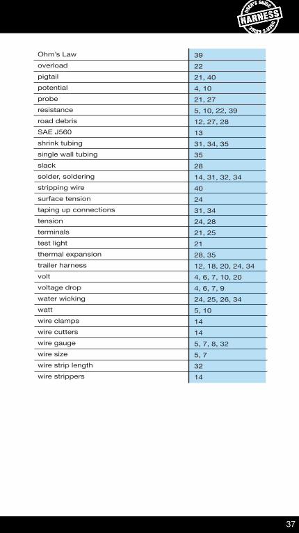
Ohm’s Lawoverloadpigtailpotentialproberesistanceroad debrisSAE J560shrink tubingsingle wall tubingslacksolder, solderingstripping wiresurface tensiontaping up connectionstensionterminalstest lightthermal expansiontrailer harnessvoltvoltage dropwater wickingwattwire clampswire cutterswire gaugewire sizewire strip lengthwire strippers
392221, 404, 1021, 275, 10, 22, 39 12, 27, 281331, 34, 35352814, 31, 32, 34402431, 3424, 2821, 252128, 3512, 18, 20, 24, 344, 6, 7, 10, 20 4, 6, 7, 924, 25, 26, 345, 1014145, 7, 8, 325, 73214

38
Index/Glossary
Glossary
Continuity - The uninterrupted, unbroken state of a current throughout a system.
Custom Cut - A term that refers to the harasses that must be cut and terminated to the customer’s specifications.
Crimping Wire - The method of connecting separate strands of wire by inserting them into a clam-type connector that carries the current from one wire to the other.
DOT - The United States Department of Transportation, which was created to serve the United States by ensuring a fast, safe, efficient, accessible and convenient transportation system that meets national interests and enhances the quality of life of the American people.
Grommet - A rubber device used to mount a lamp into a hole in a vehicle’s body or onto a mounting bracket. The grommet allows a lamp to be mounted flush with the body, thereby protecting it from physical damage. A grommet also gives the lamp additional protection against shock and vibration.
Harness - A wiring device that includes multiple plug connectors and is used to control different types of lamps. Harnesses tend to be heavy-duty, jacketed cables as opposed to lighter wires that can be found in lighting plugs.
39
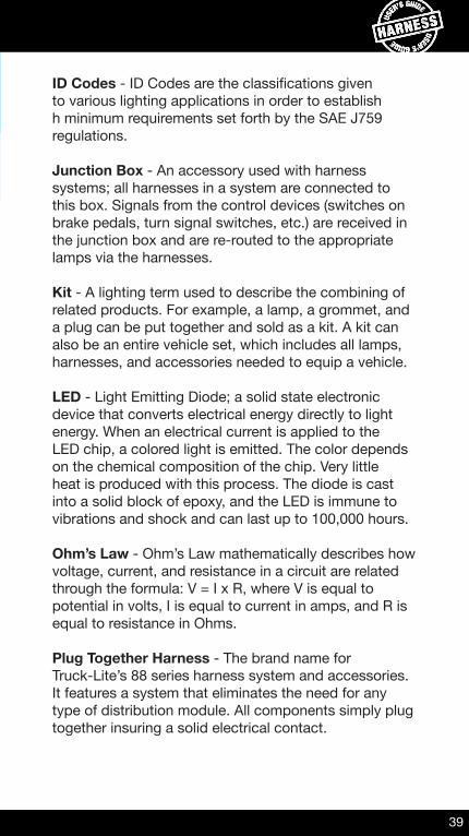
ID Codes - ID Codes are the classifications given to various lighting applications in order to establish h minimum requirements set forth by the SAE J759 regulations.
Junction Box - An accessory used with harness systems; all harnesses in a system are connected to this box. Signals from the control devices (switches on brake pedals, turn signal switches, etc.) are received in the junction box and are re-routed to the appropriate lamps via the harnesses.
Kit - A lighting term used to describe the combining of related products. For example, a lamp, a grommet, and a plug can be put together and sold as a kit. A kit can also be an entire vehicle set, which includes all lamps, harnesses, and accessories needed to equip a vehicle.
LED - Light Emitting Diode; a solid state electronic device that converts electrical energy directly to light energy. When an electrical current is applied to the LED chip, a colored light is emitted. The color depends on the chemical composition of the chip. Very little heat is produced with this process. The diode is cast into a solid block of epoxy, and the LED is immune to vibrations and shock and can last up to 100,000 hours.
Ohm’s Law - Ohm’s Law mathematically describes how voltage, current, and resistance in a circuit are related through the formula: V = I x R, where V is equal to potential in volts, I is equal to current in amps, and R is equal to resistance in Ohms.
Plug Together Harness - The brand name forTruck-Lite’s 88 series harness system and accessories. It features a system that eliminates the need for any type of distribution module. All components simply plug together insuring a solid electrical contact.
40
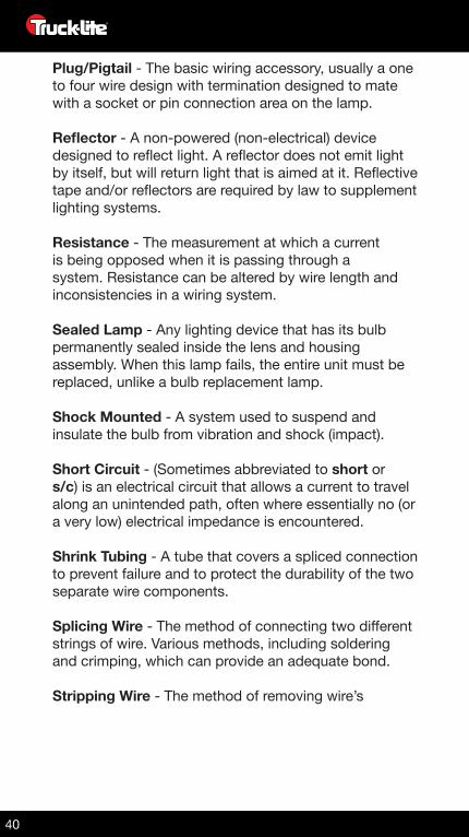
Plug/Pigtail - The basic wiring accessory, usually a one to four wire design with termination designed to mate with a socket or pin connection area on the lamp.
Reflector - A non-powered (non-electrical) device designed to reflect light. A reflector does not emit light by itself, but will return light that is aimed at it. Reflective tape and/or reflectors are required by law to supplement lighting systems.
Resistance - The measurement at which a current is being opposed when it is passing through a system. Resistance can be altered by wire length and inconsistencies in a wiring system.
Sealed Lamp - Any lighting device that has its bulb permanently sealed inside the lens and housing assembly. When this lamp fails, the entire unit must be replaced, unlike a bulb replacement lamp.
Shock Mounted - A system used to suspend and insulate the bulb from vibration and shock (impact).
Short Circuit - (Sometimes abbreviated to short or s/c) is an electrical circuit that allows a current to travel along an unintended path, often where essentially no (or a very low) electrical impedance is encountered.
Shrink Tubing - A tube that covers a spliced connection to prevent failure and to protect the durability of the two separate wire components.
Splicing Wire - The method of connecting two different strings of wire. Various methods, including soldering and crimping, which can provide an adequate bond.
Stripping Wire - The method of removing wire’s
41
insulation coating to expose the current-carrying copper inside.
Super System - The brand name for Truck-Lite’s 50 series Harnesses and accessories. This system features the custom cut and customer buildable harnesses. Compression fittings are used to seal outlets where harnesses enter the junction box.
Tail Lamp - This term is used in general to describe the rear lighting of the vehicle. Specifically, the tail lamp function is performed by the minor filament of the bulb. The red light remains on as long as the headlamps/parking lamps are in use. This light is not as bright as a turn or stop lamp.
Water Wicking - The action of water being drawn into a wire through water’s properties of adhesion. Water wicking can cause water to corrode internal areas of a wire, regardless of its direct exposure, after entering through an exposed area.
NOTES:
42
NOTES:
43
4
Truck-Lite has a proud history of quality in-house harness production and stands as a leader in the innovation of new technologies in the heavy-duty industry.
In addition to a complete offering of standard catalog and specific harnesses, Truck-Lite has engineered a wide array of molded connectors, wire types, and end seals to complement an entire line of heavy-duty lighting and visibility products. Truck-Lite offers solutions for every facet of today’s harness systems with the ability to incorporate customer specified components including grommets, split loom, tubing, braid, heat shrink, unique labels, and instructions.
Truck-Lite provides the highest levels of quality, performance, and durability in our harness products by continually working to improve equipment, processes, and production methods. We have the added strength of a fully dedicated testing facility to ensure all of our products stand up to the most rigorous of conditions. Our standard lab tests for harnesses include 500-hour corrosion testing, chemical testing, chemical compatibility checks, vibration testing hot/cold cycle exposure, salt water immersion and drop testing.
• plug to lamp interfaces with many Truck-Lite lighting products• harnesses available for both LED or Incandescent connectors,
some with internal grounds• sonic welded splices and automated terminations contained in
“sealed” molded connections• 100% electrical testing• PVC jacketed cable meets SAE recommendations• many harnesses available in 12” increments to adapt to any
application• many adapters available to tailor to specific customer requirements
Truck-Lite Harness Products offer:
442015
Designed and Printed in the U.S.A.
CORPORATE HEADQUARTERSAddress: 310 East Elmwood Avenue Falconer, NY 14733Web Site: www.truck-lite.comE-mail: [email protected]: 800.888.7095 or 716.665.6214Fax: 716.665.6403
CUSTOMER SERVICEE-mail: [email protected]: 800.562.5012 or 716.661.1162Fax: 800.685.6412 or 716.665.4825
TECHNICAL SUPPORTE-mail: [email protected]: 888.562.5012
PRODUCT ID: L181 - HARNESS USER’S GUIDE