Embed Size (px)
Citation preview
2014年泰克测试测量技术研讨会-厦门
10M-100G的通信标准全面方案
泰克科技(中国)有限公司 王宏军
Agenda
电信号通信测试方案
10M/100M/1000M/10G以太网,10G KR SFP+
光信号通信测试方案
40G/100G光通信方案
100G/400G相干光传输方案
2014/5/28 3
10M、100M、1000M以太电接口的测试
模板测试:脉冲模板、眼图模板
幅度:差分输出电压、对称度
时域:上升/下降时间、对称度、占空比失真
抖动:测试设定不同
回波损耗测试
2014/5/28 4
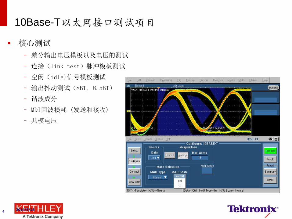
10Base-T以太网接口测试项目
核心测试
– 差分输出电压模板以及电压的测试
– 连接(link test)脉冲模板测试
– 空闲(idle)信号模板测试
– 输出抖动测试(8BT, 8.5BT)
– 谐波成分
– MDI回波损耗 (发送和接收)
– 共模电压
2014/5/28 5
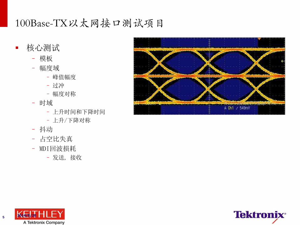
100Base-TX以太网接口测试项目
核心测试 – 模板
– 幅度域
– 峰值幅度
– 过冲
– 幅度对称
– 时域
– 上升时间和下降时间
– 上升/下降对称
– 抖动
– 占空比失真
– MDI回波损耗
– 发送, 接收
2014/5/28 6
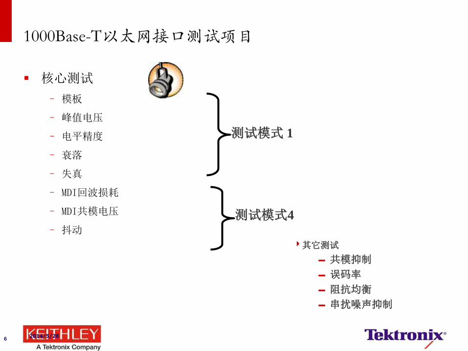
1000Base-T以太网接口测试项目
核心测试
– 模板
– 峰值电压
– 电平精度
– 衰落
– 失真
– MDI回波损耗
– MDI共模电压
– 抖动
其它测试
共模抑制
误码率
阻抗均衡
串扰噪声抑制
测试模式 1
测试模式4
2014/5/28
7
1000Base-T以太网接口测试:DUT设置
1000Base-T接口有4种IEEE组织规定的测试模式:
–测试模式1:脉冲模板测试、电压衰落测试、峰值电压测试
–测试模式2:主模式抖动
–测试模式3:从模式抖动
–测试模式4:波形失真测试、回波损耗测试、共模输出电压测试
5/28/2014
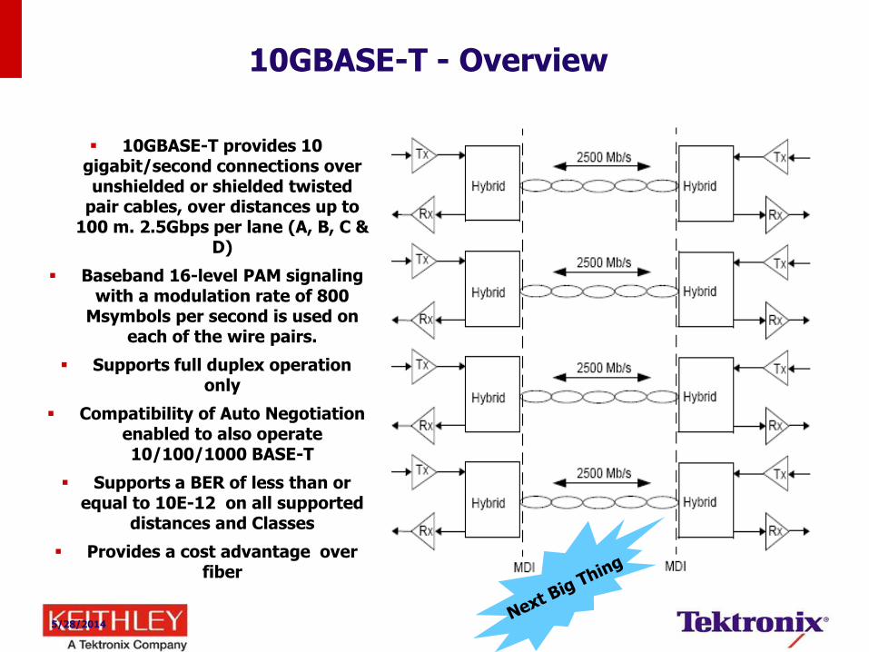
10GBASE-T - Overview
10GBASE-T provides 10 gigabit/second connections over unshielded or shielded twisted
pair cables, over distances up to 100 m. 2.5Gbps per lane (A, B, C &
D)
Baseband 16-level PAM signaling with a modulation rate of 800
Msymbols per second is used on each of the wire pairs.
Supports full duplex operation only
Compatibility of Auto Negotiation enabled to also operate 10/100/1000 BASE-T
Supports a BER of less than or equal to 10E-12 on all supported
distances and Classes
Provides a cost advantage over fiber
2014/5/28
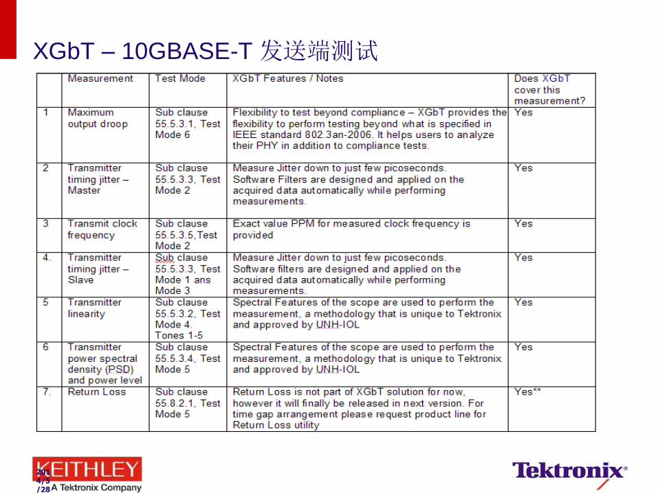
XGbT – 10GBASE-T 发送端测试

2014/5/28
Transmitter Power Spectral Density (PSD) and Power Level 发送端功率谱密度及功率值
目的 : 确保发送端功率谱密度和功率值满足规范要求。
功率值应在3.2dBm~5.2dBm范围内
功率谱密度曲线应介于规范要求的上下限曲线之间。
需进入Test Mode 5
IEEE 标准 802.3an-2006, 55.5.3.4条目。
Test Mode 5:
正常操作模式
5/28/2014
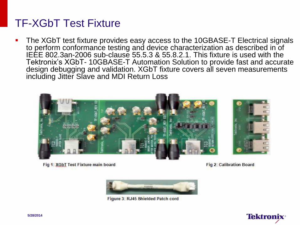
TF-XGbT Test Fixture
The XGbT test fixture provides easy access to the 10GBASE-T Electrical signals to perform conformance testing and device characterization as described in of IEEE 802.3an-2006 sub-clause 55.5.3 & 55.8.2.1. This fixture is used with the Tektronix’s XGbT- 10GBASE-T Automation Solution to provide fast and accurate design debugging and validation. XGbT fixture covers all seven measurements including Jitter Slave and MDI Return Loss
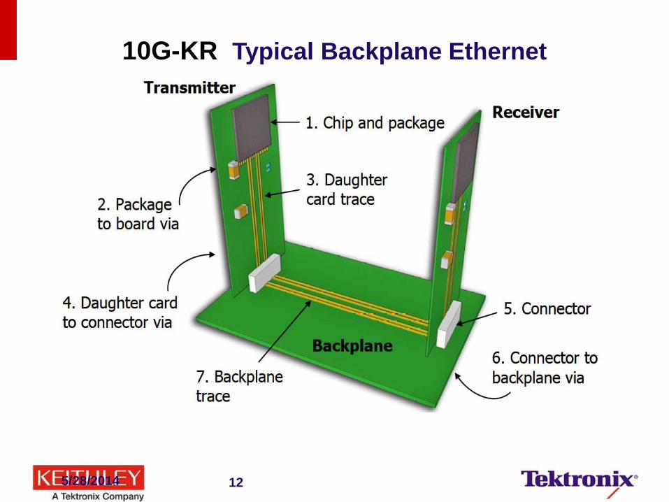
10G-KR Typical Backplane Ethernet
5/28/2014 12
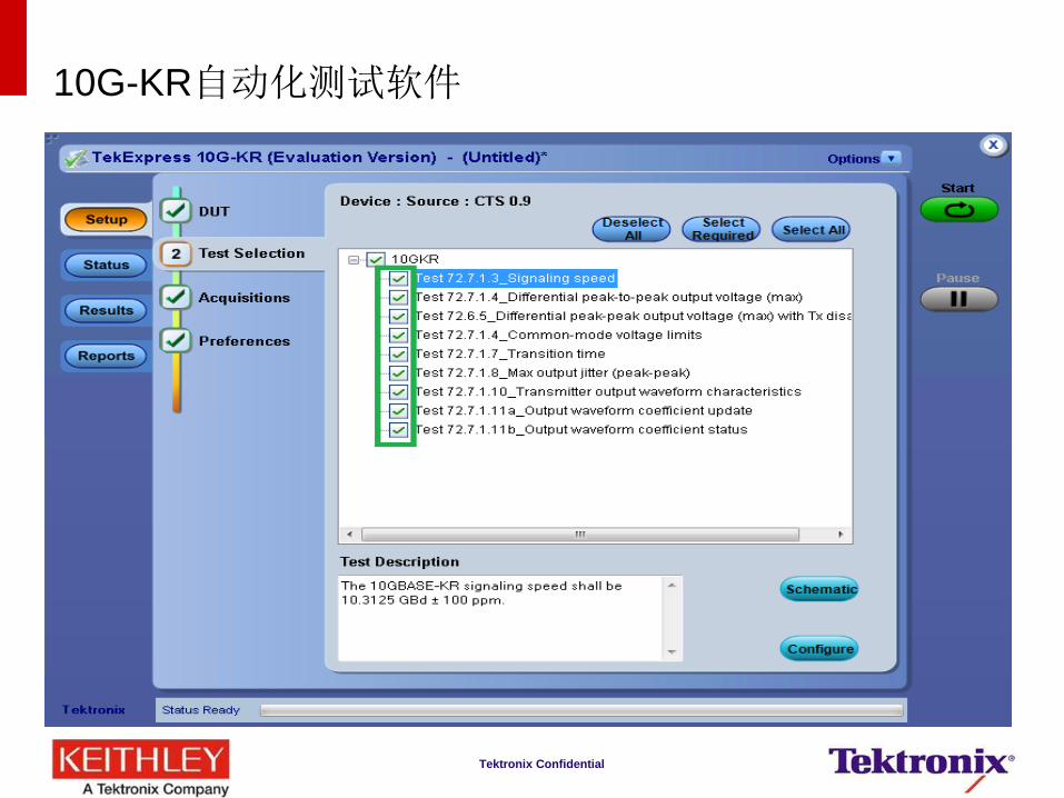
10G-KR自动化测试软件
Tektronix Confidential
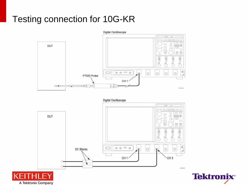
Testing connection for 10G-KR
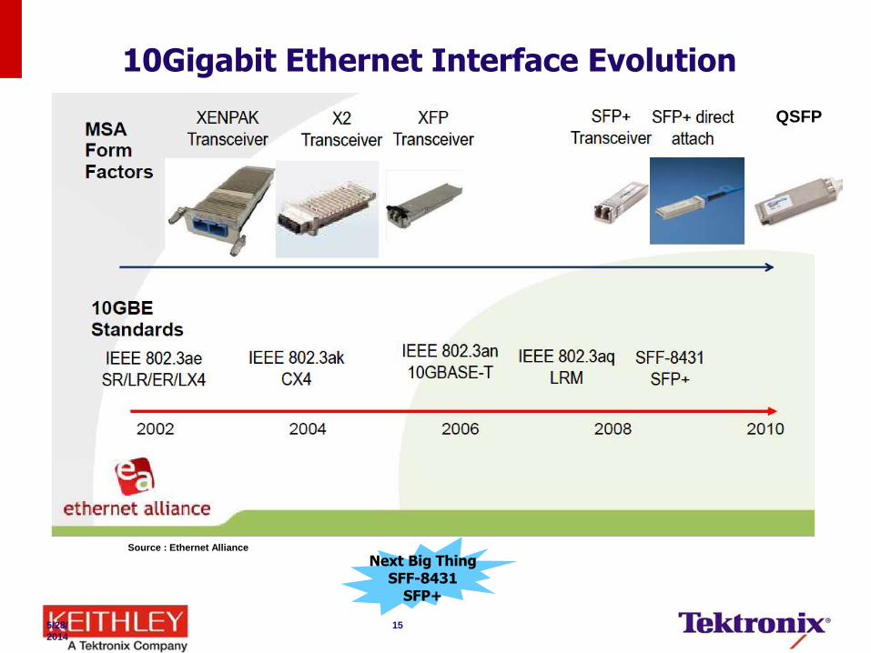
10Gigabit Ethernet Interface Evolution
Next Big Thing SFF-8431
SFP+
Source : Ethernet Alliance
5/28/
2014
15
QSFP
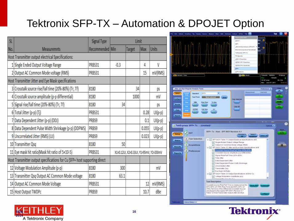
Tektronix SFP-TX – Automation & DPOJET Option
5/28/
2014
16
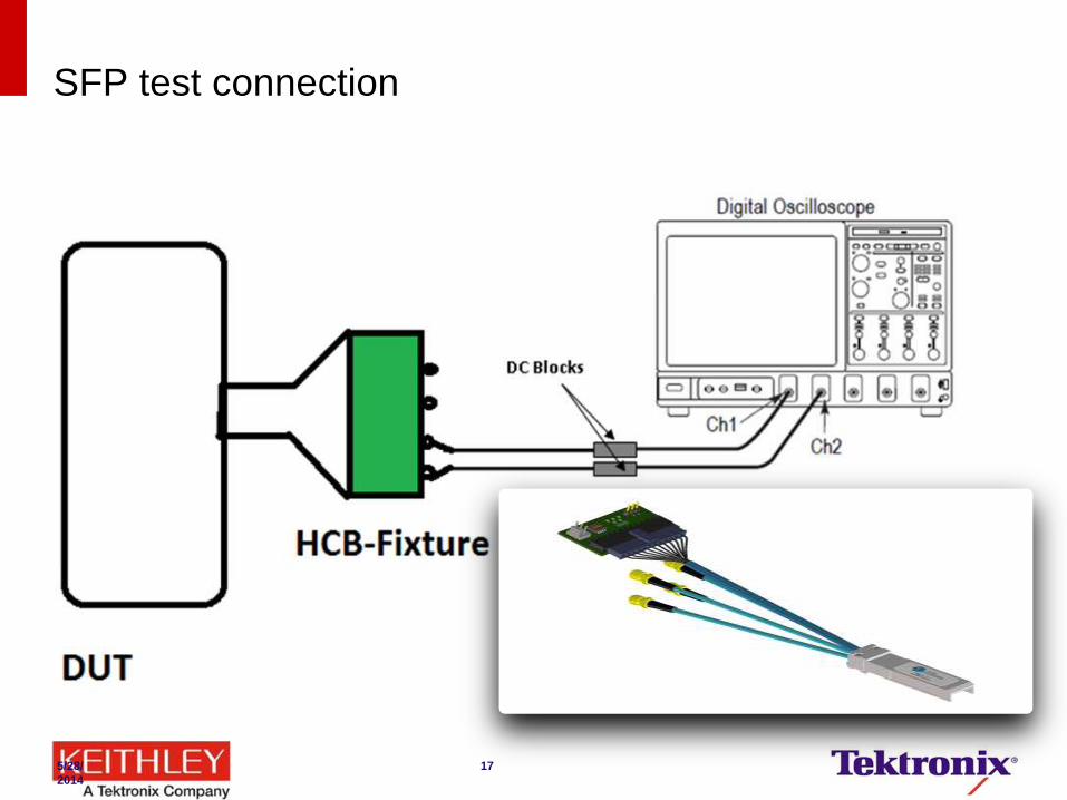
SFP test connection
5/28/
2014
17
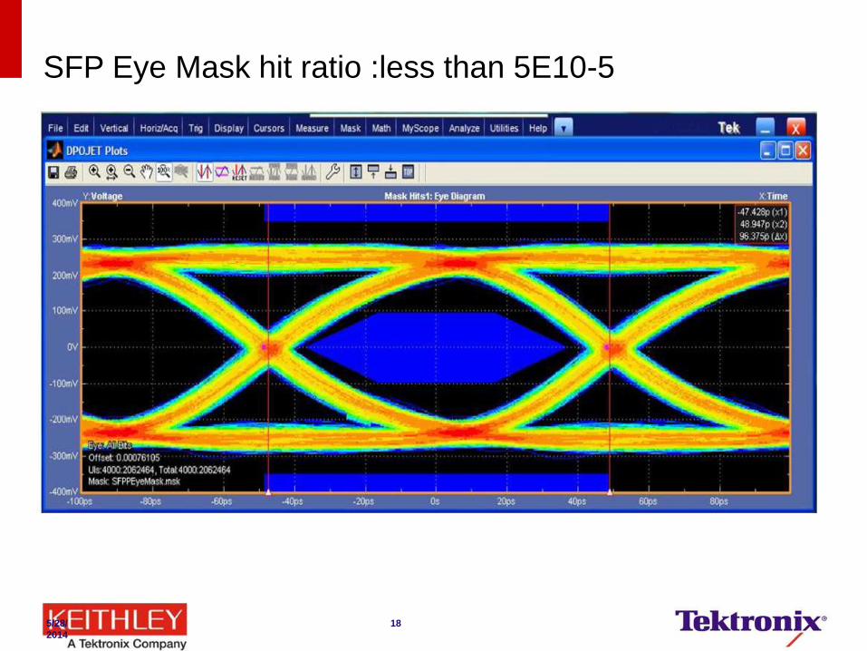
SFP Eye Mask hit ratio :less than 5E10-5
5/28/
2014
18
光通信测试方案
Telecom (125 Mb/s to 44.50 Gb/s)
Datacom (gigabit Ethernet, 10 GbE, 40 GbE,
100 GbE, Fibre Channel to 16 GFC, and
InfiniBand) solution
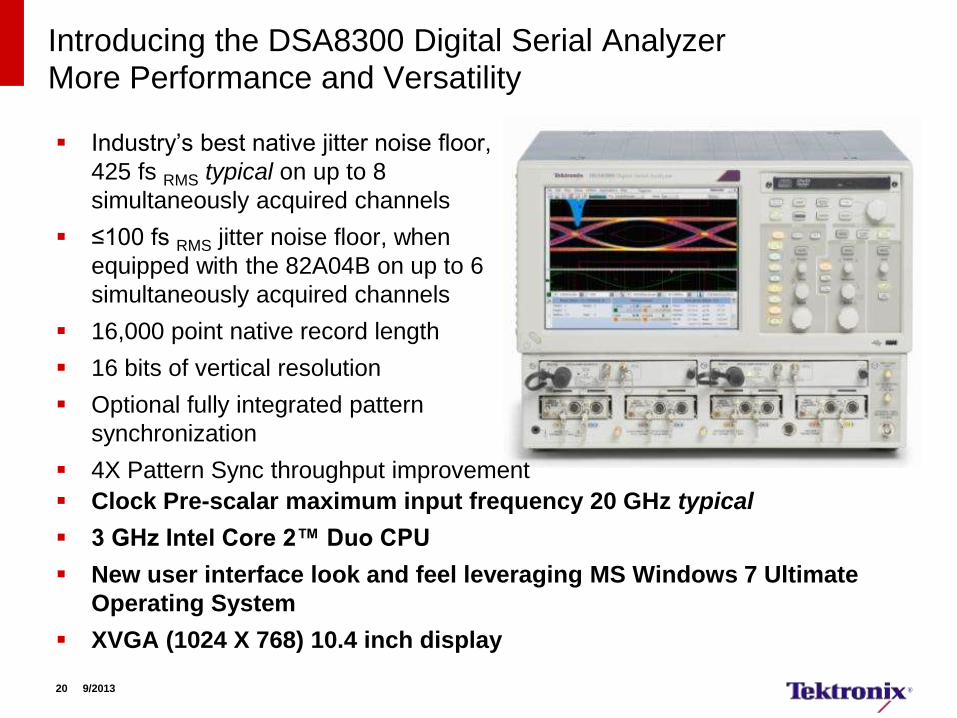
Introducing the DSA8300 Digital Serial Analyzer More Performance and Versatility
Industry’s best native jitter noise floor,
425 fs RMS typical on up to 8
simultaneously acquired channels
≤100 fs RMS jitter noise floor, when
equipped with the 82A04B on up to 6
simultaneously acquired channels
16,000 point native record length
16 bits of vertical resolution
Optional fully integrated pattern
synchronization
4X Pattern Sync throughput improvement
Clock Pre-scalar maximum input frequency 20 GHz typical
3 GHz Intel Core 2™ Duo CPU
New user interface look and feel leveraging MS Windows 7 Ultimate
Operating System
XVGA (1024 X 768) 10.4 inch display
20 9/2013
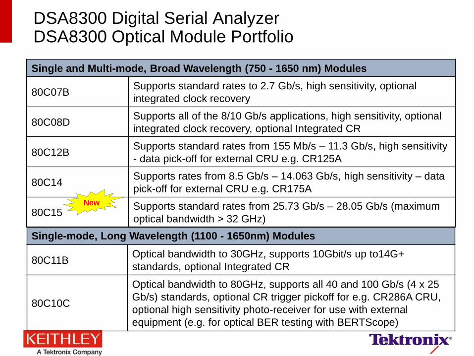
DSA8300 Digital Serial Analyzer DSA8300 Optical Module Portfolio
Single and Multi-mode, Broad Wavelength (750 - 1650 nm) Modules
80C07B Supports standard rates to 2.7 Gb/s, high sensitivity, optional
integrated clock recovery
80C08D Supports all of the 8/10 Gb/s applications, high sensitivity, optional
integrated clock recovery, optional Integrated CR
80C12B Supports standard rates from 155 Mb/s – 11.3 Gb/s, high sensitivity
- data pick-off for external CRU e.g. CR125A
80C14 Supports rates from 8.5 Gb/s – 14.063 Gb/s, high sensitivity – data
pick-off for external CRU e.g. CR175A
80C15 Supports standard rates from 25.73 Gb/s – 28.05 Gb/s (maximum
optical bandwidth > 32 GHz)
Single-mode, Long Wavelength (1100 - 1650nm) Modules
80C11B Optical bandwidth to 30GHz, supports 10Gbit/s up to14G+
standards, optional Integrated CR
80C10C
Optical bandwidth to 80GHz, supports all 40 and 100 Gb/s (4 x 25
Gb/s) standards, optional CR trigger pickoff for e.g. CR286A CRU,
optional high sensitivity photo-receiver for use with external
equipment (e.g. for optical BER testing with BERTScope)
New
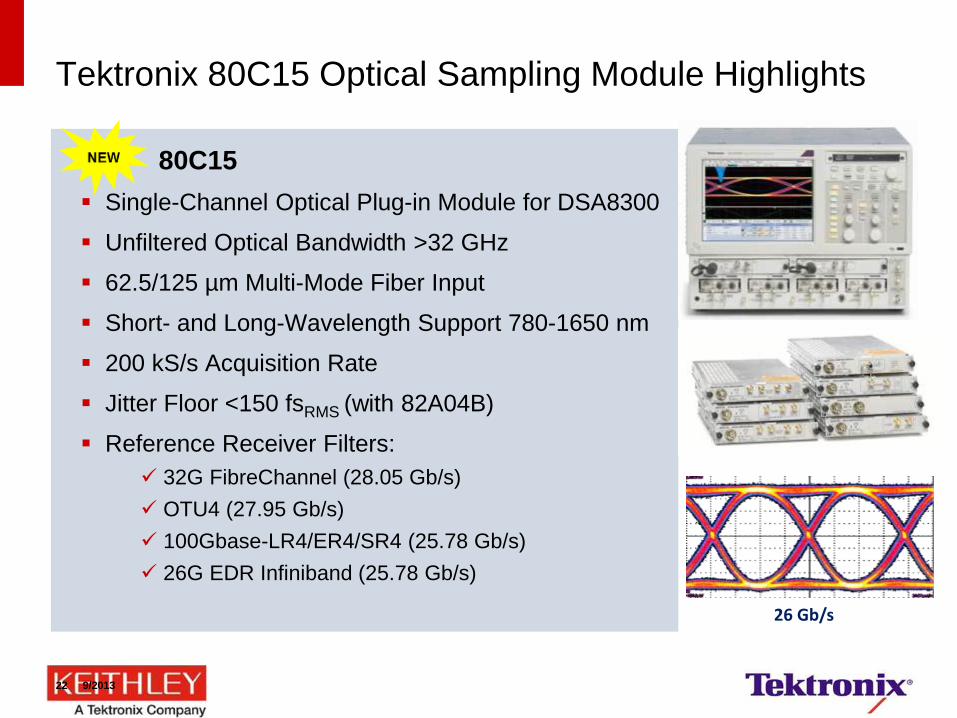
80C15
Single-Channel Optical Plug-in Module for DSA8300
Unfiltered Optical Bandwidth >32 GHz
62.5/125 µm Multi-Mode Fiber Input
Short- and Long-Wavelength Support 780-1650 nm
200 kS/s Acquisition Rate
Jitter Floor <150 fsRMS (with 82A04B)
Reference Receiver Filters:
32G FibreChannel (28.05 Gb/s)
OTU4 (27.95 Gb/s)
100Gbase-LR4/ER4/SR4 (25.78 Gb/s)
26G EDR Infiniband (25.78 Gb/s)
Tektronix 80C15 Optical Sampling Module Highlights
26 Gb/s
22 9/2013
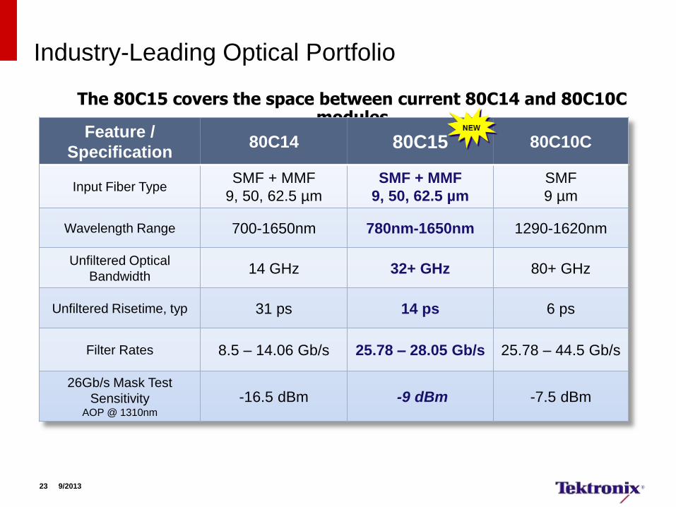
Industry-Leading Optical Portfolio
The 80C15 covers the space between current 80C14 and 80C10C modules
Feature /
Specification 80C14 80C15 80C10C
Input Fiber Type SMF + MMF
9, 50, 62.5 µm
SMF + MMF
9, 50, 62.5 µm
SMF
9 µm
Wavelength Range 700-1650nm 780nm-1650nm 1290-1620nm
Unfiltered Optical
Bandwidth 14 GHz 32+ GHz 80+ GHz
Unfiltered Risetime, typ 31 ps 14 ps 6 ps
Filter Rates 8.5 – 14.06 Gb/s 25.78 – 28.05 Gb/s 25.78 – 44.5 Gb/s
26Gb/s Mask Test
Sensitivity AOP @ 1310nm
-16.5 dBm -9 dBm -7.5 dBm
23 9/2013
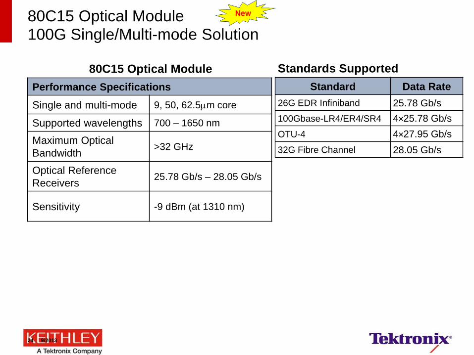
80C15 Optical Module 100G Single/Multi-mode Solution
Standards Supported
Standard Data Rate
26G EDR Infiniband 25.78 Gb/s
100Gbase-LR4/ER4/SR4 4×25.78 Gb/s
OTU-4 4×27.95 Gb/s
32G Fibre Channel 28.05 Gb/s
80C15 Optical Module
Performance Specifications
Single and multi-mode 9, 50, 62.5m core
Supported wavelengths 700 – 1650 nm
Maximum Optical
Bandwidth >32 GHz
Optical Reference
Receivers 25.78 Gb/s – 28.05 Gb/s
Sensitivity -9 dBm (at 1310 nm)
24 9/2013
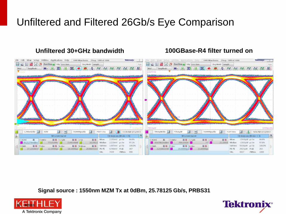
Unfiltered and Filtered 26Gb/s Eye Comparison
Unfiltered 30+GHz bandwidth
Signal source : 1550nm MZM Tx at 0dBm, 25.78125 Gb/s, PRBS31
100GBase-R4 filter turned on
25 9/2013
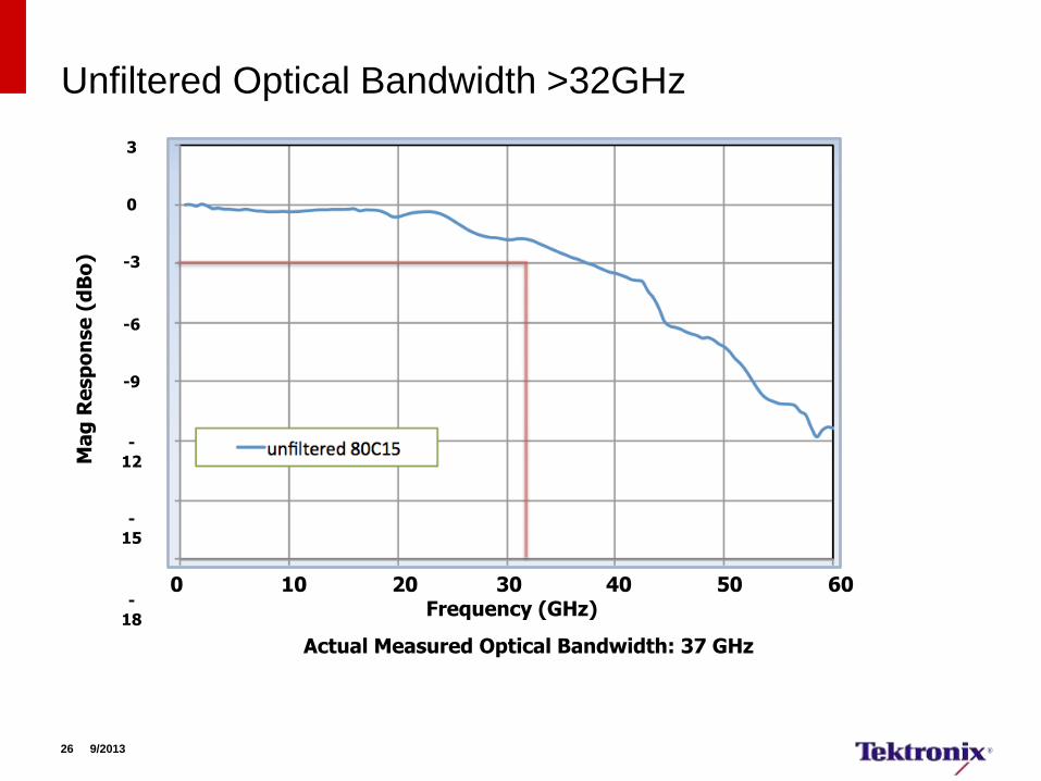
Unfiltered Optical Bandwidth >32GHz
Actual Measured Optical Bandwidth: 37 GHz
0 10 20 30 40 50 60 Frequency (GHz)
3
0
-3
-6
-9
-
12 -
15
-
18
Ma
g R
esp
on
se
(d
Bo
)
26 9/2013
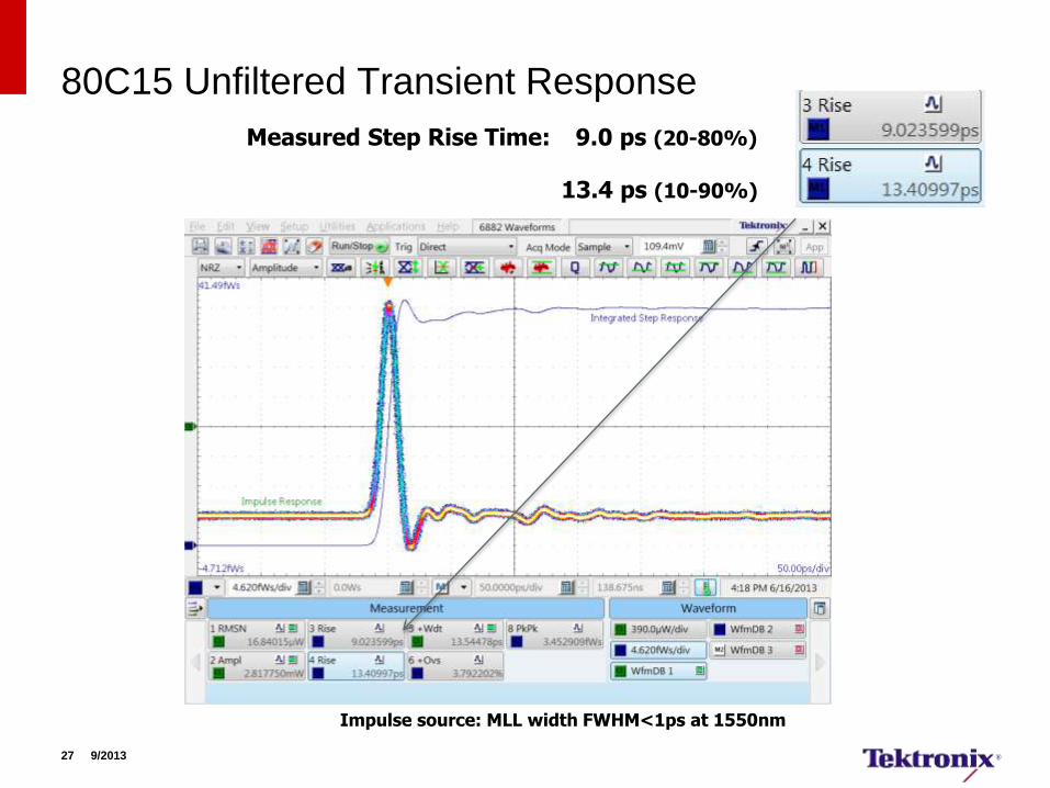
80C15 Unfiltered Transient Response
Measured Step Rise Time: 9.0 ps (20-80%)
13.4 ps (10-90%)
Impulse source: MLL width FWHM<1ps at 1550nm
27 9/2013
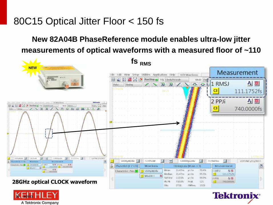
80C15 Optical Jitter Floor < 150 fs
New 82A04B PhaseReference module enables ultra-low jitter
measurements of optical waveforms with a measured floor of ~110
fs RMS
28GHz optical CLOCK waveform
28 9/2013

80C14 Optical Module 16 GFC Single/Multi-mode Solution
Standards Supported
Standard Data Rate
8 GFC (old) 8.500 Gb/s
OC192/STM64 9.953 Gb/s
10GBase-W 9.953 Gb/s
10GBase-R 10.31 Gb/s
40GBase-LR4 9.953 Gb/s
10G EPON 9.953 Gb/s
100GBase-SR10 10.31 Gb/s
10GFC 10.51 Gb/s
G.975 FEC 10.66 Gb/s
G.709 FEC 10.71 Gb/s
10GBE FEC 11.10 Gb/s
10 GFC FEC 11.317Gb/s
12.5 Gb/s FEC 12.50 Gb/s
16 GFC 14.025 Gb/s
Infiniband FDR 14.063 Gb/s
80C14 Optical Module
Performance Specifications
Single and multi-mode 9, 50, 62.5m core
Supported wavelengths 700 – 1650 nm
Maximum Optical
Bandwidth 14 GHz
Optical Reference
Receivers
All 10 Gb/s standards
+ 8 and 16 GFC
Sensitivity -12 dBm at 850nm
(-15 dBm at 1310 nm)
Buffered electrical data
pick-off to support
external clock recovery
instrument
Recommended
Tektronix CR175A or
CR286A
29 9/2013
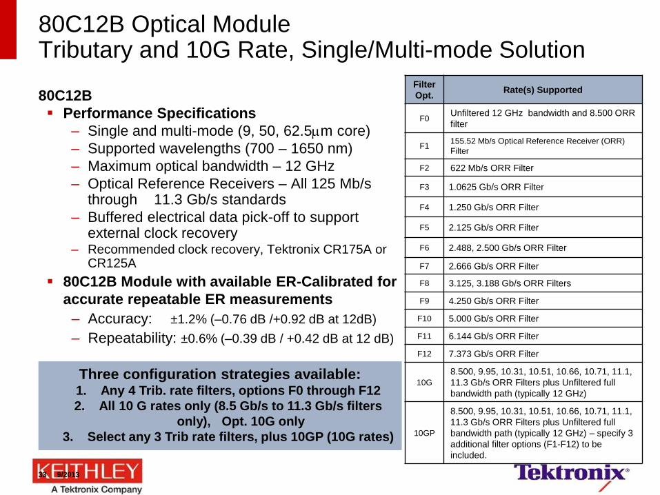
80C12B Optical Module Tributary and 10G Rate, Single/Multi-mode Solution
80C12B
Performance Specifications
– Single and multi-mode (9, 50, 62.5m core)
– Supported wavelengths (700 – 1650 nm)
– Maximum optical bandwidth – 12 GHz
– Optical Reference Receivers – All 125 Mb/s through 11.3 Gb/s standards
– Buffered electrical data pick-off to support external clock recovery
– Recommended clock recovery, Tektronix CR175A or CR125A
80C12B Module with available ER-Calibrated for
accurate repeatable ER measurements
– Accuracy: ±1.2% (–0.76 dB /+0.92 dB at 12dB)
– Repeatability: ±0.6% (–0.39 dB / +0.42 dB at 12 dB)
Three configuration strategies available: 1. Any 4 Trib. rate filters, options F0 through F12
2. All 10 G rates only (8.5 Gb/s to 11.3 Gb/s filters
only), Opt. 10G only
3. Select any 3 Trib rate filters, plus 10GP (10G rates)
Filter
Opt. Rate(s) Supported
F0 Unfiltered 12 GHz bandwidth and 8.500 ORR
filter
F1 155.52 Mb/s Optical Reference Receiver (ORR)
Filter
F2 622 Mb/s ORR Filter
F3 1.0625 Gb/s ORR Filter
F4 1.250 Gb/s ORR Filter
F5 2.125 Gb/s ORR Filter
F6 2.488, 2.500 Gb/s ORR Filter
F7 2.666 Gb/s ORR Filter
F8 3.125, 3.188 Gb/s ORR Filters
F9 4.250 Gb/s ORR Filter
F10 5.000 Gb/s ORR Filter
F11 6.144 Gb/s ORR Filter
F12 7.373 Gb/s ORR Filter
10G
8.500, 9.95, 10.31, 10.51, 10.66, 10.71, 11.1,
11.3 Gb/s ORR Filters plus Unfiltered full
bandwidth path (typically 12 GHz)
10GP
8.500, 9.95, 10.31, 10.51, 10.66, 10.71, 11.1,
11.3 Gb/s ORR Filters plus Unfiltered full
bandwidth path (typically 12 GHz) – specify 3
additional filter options (F1-F12) to be
included.
33 9/2013
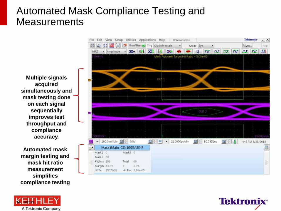
Automated Mask Compliance Testing and Measurements
Multiple signals
acquired
simultaneously and
mask testing done
on each signal
sequentially
improves test
throughput and
compliance
accuracy.
Automated mask
margin testing and
mask hit ratio
measurement
simplifies
compliance testing
34 9/2013
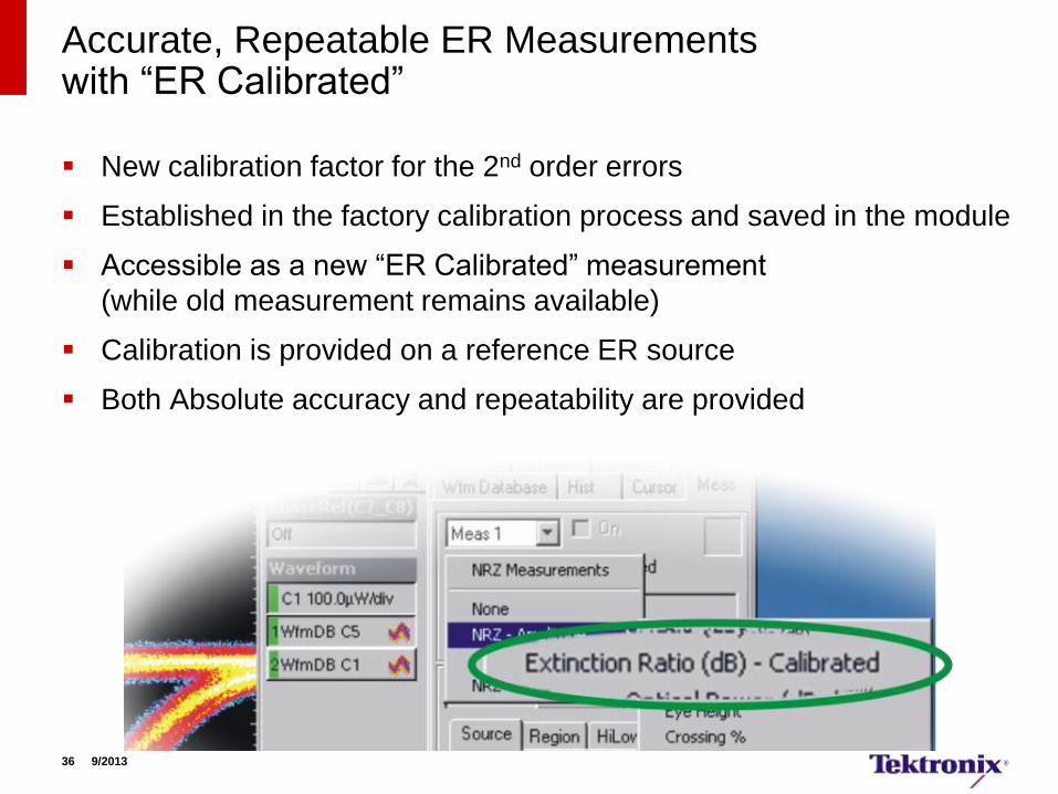
Accurate, Repeatable ER Measurements with “ER Calibrated”
New calibration factor for the 2nd order errors
Established in the factory calibration process and saved in the module
Accessible as a new “ER Calibrated” measurement
(while old measurement remains available)
Calibration is provided on a reference ER source
Both Absolute accuracy and repeatability are provided
36 9/2013
ER Calibrated Measurement Confidence and Improved Yields
ER Calibrated: Guaranteed Absolute Accuracy: – +/- 1.2 % (-0.49dB /+0. 56dB @ 10 dB)
ER Calibrated: Typical Repeatability: – +/- 0.6 % (-0.25dB / +0.27dB @ 10 dB)
Removal of 2nd order effects improves the repeatability and absolute accuracy of ER result for the industry
The result is guaranteed against Tektronix calibration reference source and against Tektronix verification signal
For manufacturing this means:
– Better yield, or longer reach, or better margins
For component and module manufacturers and module users this
means
– Clarity on quality and compliance
As the usage of the ER Calibrated grows, you can increase your
competitiveness with DSA8300 “ER Calibrated”
37 9/2013
DSA8300 ER Calibrated Order New or Upgrade Your Existing Modules
ER Calibrated is available on new DSA8300/8200 Optical Modules
as Option 01 for:
– 80C12B
– 80C08D
– 80C11B
– 80C02
ER Calibrated can be added to your existing 8000 Series Optical
Modules by ordering 80CUP, Opt. 01 for the same modules.
– Requires 8000 Series mainframe running Windows® XP or Windows® 7
operating systems
38 9/2013
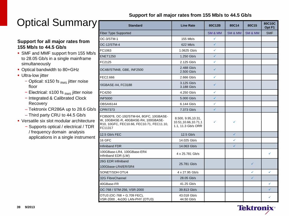
Optical Summary
Support for all major rates from
155 Mb/s to 44.5 Gb/s
SMF and MMF support from 155 Mb/s
to 28.05 Gb/s in a single mainframe
simultaneously
Optical bandwidth to 80+GHz
Ultra-low jitter
− Optical: ≤150 fs RMS jitter noise
floor
− Electrical: ≤100 fs RMS jitter noise
− Integrated & Calibrated Clock
Recovery
– Tektronix CR286A up to 28.6 Gb/s
– Third party CRU to 44.5 Gb/s
Versatile six slot modular architecture
− Supports optical / electrical / TDR
/ frequency domain analysis
applications in a single instrument
Standard Line Rate 80C12B 80C14 80C15 80C10C
Opt F1
Fiber Type Supported SM & MM SM & MM SM & MM SMF
OC-3/STM-1 155 Mb/s
OC-12/STM-4 622 Mb/s
FC1063 1.0625 Gb/s
ENET1250 1.250 Gb/s
FC2125 2.125 Gb/s
OC48//STM48, GBE, INF2500 2.488 Gb/s
2.500 Gb/s
FEC2.666 2.666 Gb/s
!0GBASE-X4, FC3188 3.125 Gb/s
3.188 Gb/s
FC4250 4.250 Gb/s
INF5000 5.000 Gb/s
OBSAI6144 6.144 Gb/s
CPRI7373 7.373 Gb/s
FC8500*8, OC-192/STM-64, 8GFC, 10GBASE-
W, 10GBASE-R, 40GBASE-R4, 100GBASE-
R10, 10GFC, FEC10.66, FEC10.71, FEC11.10,
FC11317
8.500, 9.95,10.31,
10.51,10.66,10.71,1
1.1, 11.3 Gb/s ORR
12.5 Gb/s FEC 12.5 Gb/s
16 GFC 14.025 Gb/s
Infiniband FDR 14.063 Gb/s
100GBase-LR4, 100GBase-ER4
Infiniband EDR (LW) 4 x 25.781 Gb/s
26G EDR Infiniband
100Gbase-LR4/ER/SR4 25.781 Gb/s
SONET/SDH OTU4 4 x 27.95 Gb/s
32G FibreChannel 28.05 Gb/s
40GBase-FR 41.25 Gb/s
OC-768 / STM-256, VSR-2000 39.813 Gb/s
OTU3 (OC-768 + G.709 FEC),
VSR-2000 , 4x10G LAN-PHY (OTU3)
43.018 Gb/s
44.50 Gb/s
39 9/2013
Support for all major rates from 155 Mb/s to 44.5 Gb/s
Key specifications and ordering information
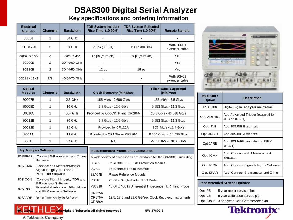
DSA8300 Digital Serial Analyzer
Electrical
Modules
Channels
Bandwidth
TDR System Incident
Rise Time (10-90%)
TDR System Reflected
Rise Time (10-90%)
Remote Sampler
80E01 1 50 GHz - - -
80E03 / 04 2 20 GHz 23 ps (80E04) 28 ps (80E04) With 80N01
extender cable
80E07B / 8B 2 20/30 GHz 18 ps (80E08B) 20 ps(80E08B) Yes
80E09B 2 30/40/60 GHz - - Yes
80E10B 2 30/40/50 GHz 12 ps 15 ps Yes
80E11 / 11X1 2/1 40/60/70 GHz - - With 80N01
extender cable
Optical
Modules
Channels
Bandwidth
Clock Recovery (Min/Max)
Filter Rates Supported
(Min/Max)
80C07B 1 2.5 GHz 155 Mb/s - 2.666 Gb/s 155 Mb/s - 2.5 Gb/s
80C08D 1 10 GHz 9.8 Gb/s - 12.6 Gb/s 9.953 Gb/s - 11.3 Gb/s
80C10C 1 80+ GHz Provided by Opt CRTP and CR286A 25.8 Gb/s - 43.018 Gb/s
80C11B 1 30 GHz 9.8 Gb/s - 12.6 Gb/s 9.953 Gb/s - 11.3 Gb/s
80C12B 1 12 GHz Provided by CR125A 155 Mb/s - 11.4 Gb/s
80C14 1 14 GHz Provided by CR175A or CR286A 8.500 Gb/s - 14.025 Gb/s
80C15 1 32 GHz NA 25.78 Gb/s - 28.05 Gb/s
Recommended Probes and Accessories
A wide variety of accessories are available for the DSA8300, including:
80A02 DSA8300 EOS/ESD Protection Module
80A03 TekConnect Probe Interface
82A04B Phase Reference Module
P8018 20 GHz Single-Ended TDR Probe
P80318 18 GHz 100 Ω Differential Impedance TDR Hand Probe
CR125A
CR175A
CR286A
12.5, 17.5 and 28.6 GB/sec Clock Recovery Instruments
Key Analysis Software
80SSPAR IConnect S-Parameters and Z-Line
Software
80SICMX IConnect and MeasureXtractor
Signal Integrity TDR and S-
Parameter Software
80SICON
80SJNB
IConnect Signal Integrity TDR and
S-Parameter Software
Essential & Advanced Jitter, Noise
and BER Analysis Software
80SJARB Basic Jitter Analysis Software
DSA8300 /
Option Description
DSA8300 Digital Signal Analyzer mainframe
Opt. ADTRIG Add Advanced Trigger (required for
JNB or JNB01)
Opt. JNB Add 80SJNB Essentials
Opt. JNB01 Add 80SJNB Advanced
Opt JARB Add 80SJARB (included in JNB &
JNB01)
Opt. ICMX Add IConnect with Measurement
Extractor
Opt. ICON Add IConnect Signal Integrity Software
Opt. SPAR Add IConnect S-parameter and Z-line
Recommended Service Options:
Opt. R5 5 year repair service plan
Opt. C5 5 year calibration service plan
Opt G3/G5 3 or 5 year Gold Care service plan
40 . 9/2013 Copyright © Tektronix All rights reserved8 5W-27809-6
Outline
Coherent Optical Solution
Intradyne Coherent Receiver(ICR) test
Multi-carrier Support for 400G/1T (NEW!)
Summary/Conclusion
42 3/2013 52W-27502-3
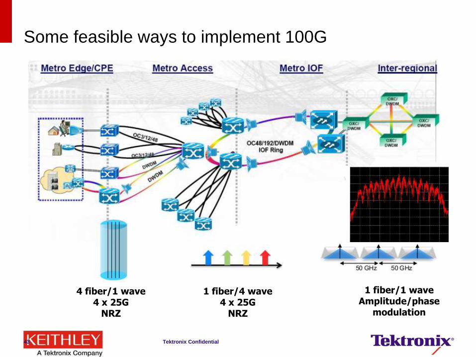
Some feasible ways to implement 100G
Tektronix Confidential 43
4 fiber/1 wave 4 x 25G
NRZ
1 fiber/4 wave 4 x 25G
NRZ
1 fiber/1 wave Amplitude/phase
modulation
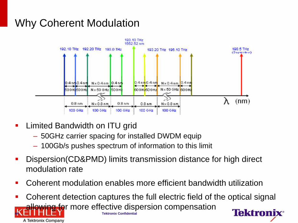
Why Coherent Modulation
Limited Bandwidth on ITU grid
– 50GHz carrier spacing for installed DWDM equip
– 100Gb/s pushes spectrum of information to this limit
Dispersion(CD&PMD) limits transmission distance for high direct
modulation rate
Coherent modulation enables more efficient bandwidth utilization
Coherent detection captures the full electric field of the optical signal
allowing for more effective dispersion compensation Tektronix Confidential 44
Compelling advantage for coherent
Higher bit rates per wavelength have best
economics
Bandwidth and link quality set by infrastructure
Complex modulation allows more bits per hertz
Coherent detection – Enables software-based impairment compensation
– Provides highest bits/hertz
– Enables huge selection of modulation formats
– Huge success in longhaul may lead to other
applications
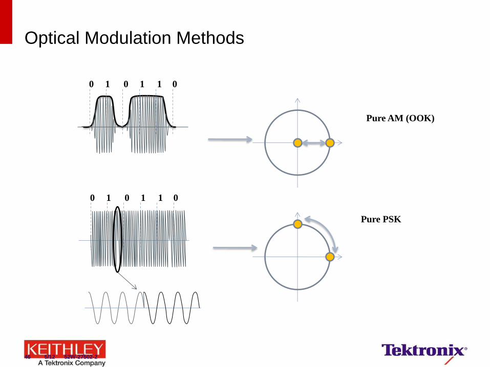
Optical Modulation Methods
0 1 0 1 1 0
0 1 0 1 1 0
Pure AM (OOK)
Pure PSK
46 5/12 52W-27502-2
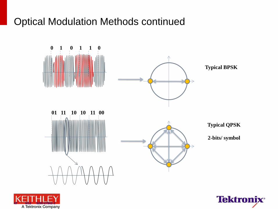
Optical Modulation Methods continued
0 1 0 1 1 0
01 11 10 10 11 00
Typical BPSK
Typical QPSK
2-bits/ symbol
47 5/12 52W-27502-2
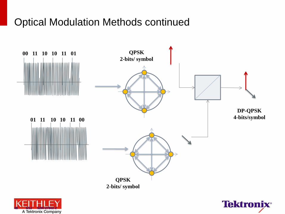
Optical Modulation Methods continued
01 11 10 10 11 00
01 11 10 10 11 00
DP-QPSK
4-bits/symbol
QPSK
2-bits/ symbol
QPSK
2-bits/ symbol
48 5/12 52W-27502-2
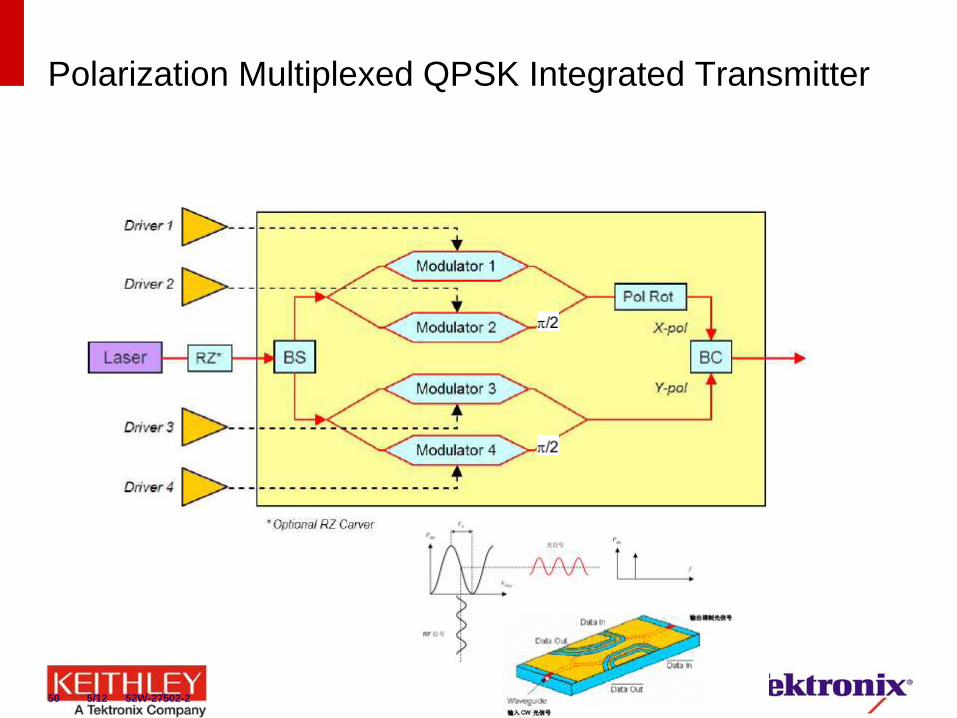
Polarization Multiplexed QPSK Integrated Transmitter
50 5/12 52W-27502-2
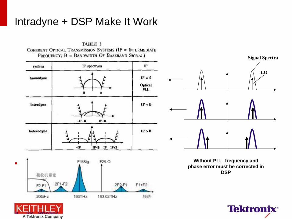
Intradyne + DSP Make It Work
Derr, 1992, PTL
Signal Spectra
LO
Without PLL, frequency and
phase error must be corrected in
DSP
51 5/12 52W-27502-2
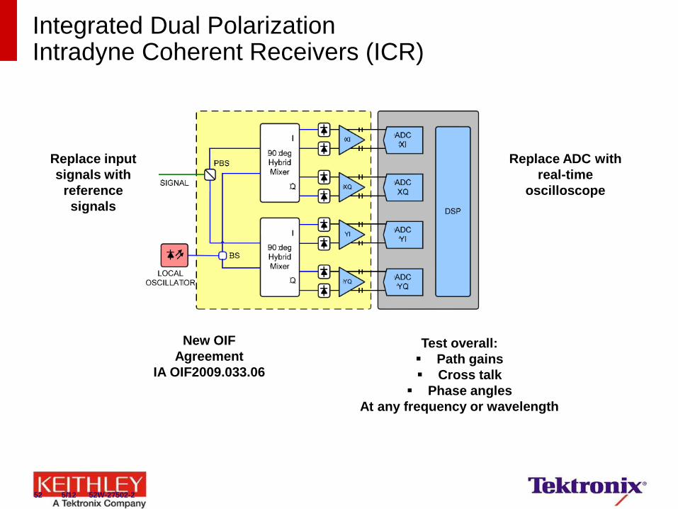
Integrated Dual Polarization Intradyne Coherent Receivers (ICR)
New OIF
Agreement
IA OIF2009.033.06
Replace input
signals with
reference
signals
Replace ADC with
real-time
oscilloscope
Test overall:
Path gains
Cross talk
Phase angles
At any frequency or wavelength
52 5/12 52W-27502-2
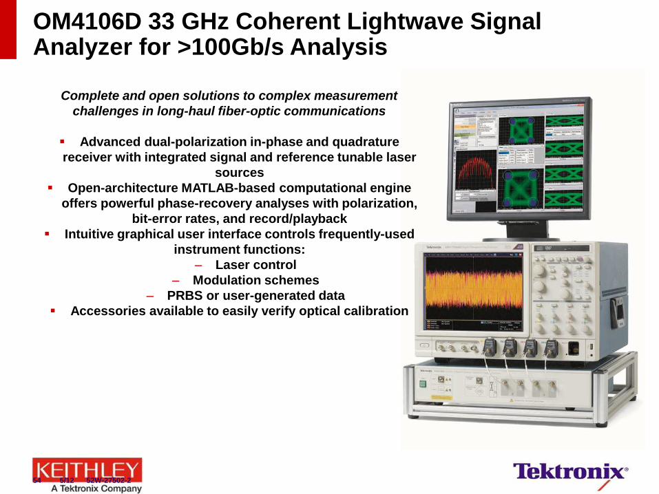
Complete and open solutions to complex measurement
challenges in long-haul fiber-optic communications
Advanced dual-polarization in-phase and quadrature
receiver with integrated signal and reference tunable laser
sources
Open-architecture MATLAB-based computational engine
offers powerful phase-recovery analyses with polarization,
bit-error rates, and record/playback
Intuitive graphical user interface controls frequently-used
instrument functions:
– Laser control
– Modulation schemes
– PRBS or user-generated data
Accessories available to easily verify optical calibration
OM4106D 33 GHz Coherent Lightwave Signal Analyzer for >100Gb/s Analysis
54 5/12 52W-27502-2
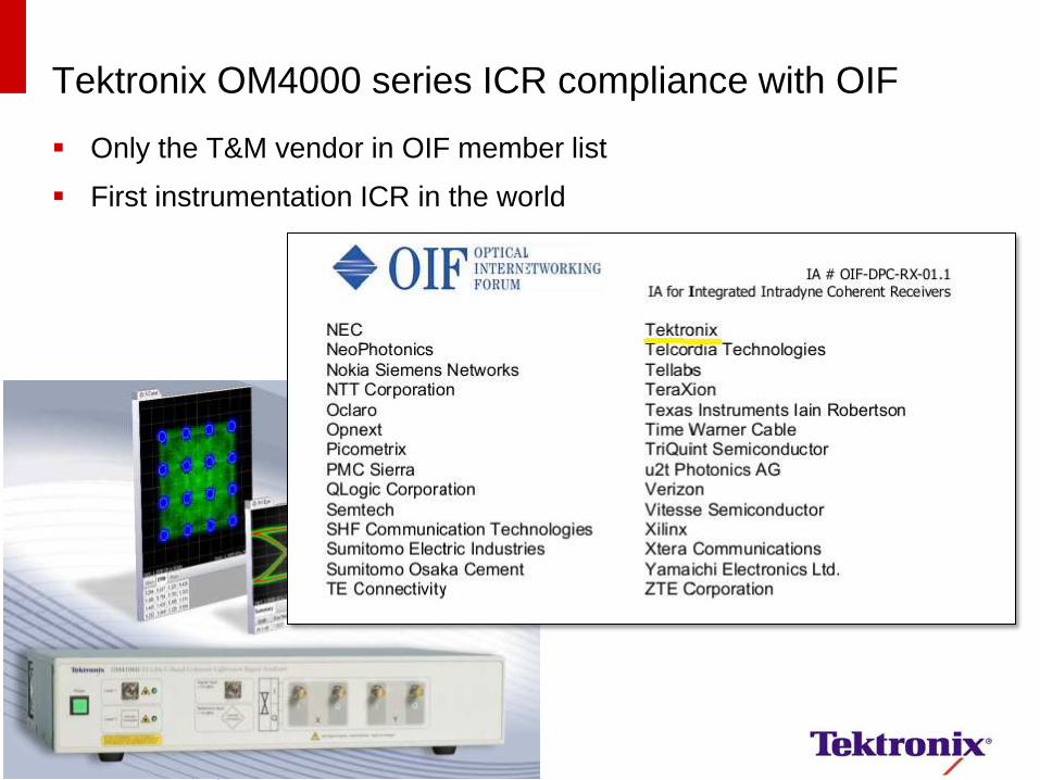
Tektronix OM4000 series ICR compliance with OIF
Only the T&M vendor in OIF member list
First instrumentation ICR in the world
Tektronix Confidential 55
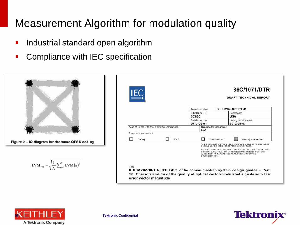
Measurement Algorithm for modulation quality
Industrial standard open algorithm
Compliance with IEC specification
Tektronix Confidential 56
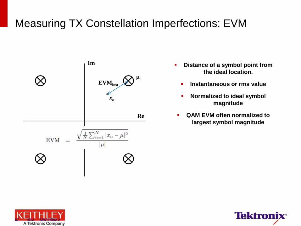
Measuring TX Constellation Imperfections: EVM
Distance of a symbol point from
the ideal location.
Instantaneous or rms value
Normalized to ideal symbol
magnitude
QAM EVM often normalized to
largest symbol magnitude
EVMinst
xn
Re
Im
57 5/12 52W-27502-2
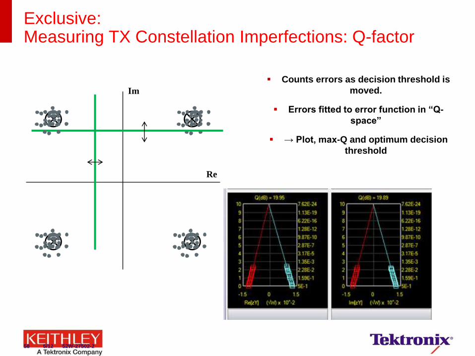
Exclusive: Measuring TX Constellation Imperfections: Q-factor
Re
Im
Counts errors as decision threshold is
moved.
Errors fitted to error function in “Q-
space”
→ Plot, max-Q and optimum decision
threshold
58 5/12 52W-27502-2
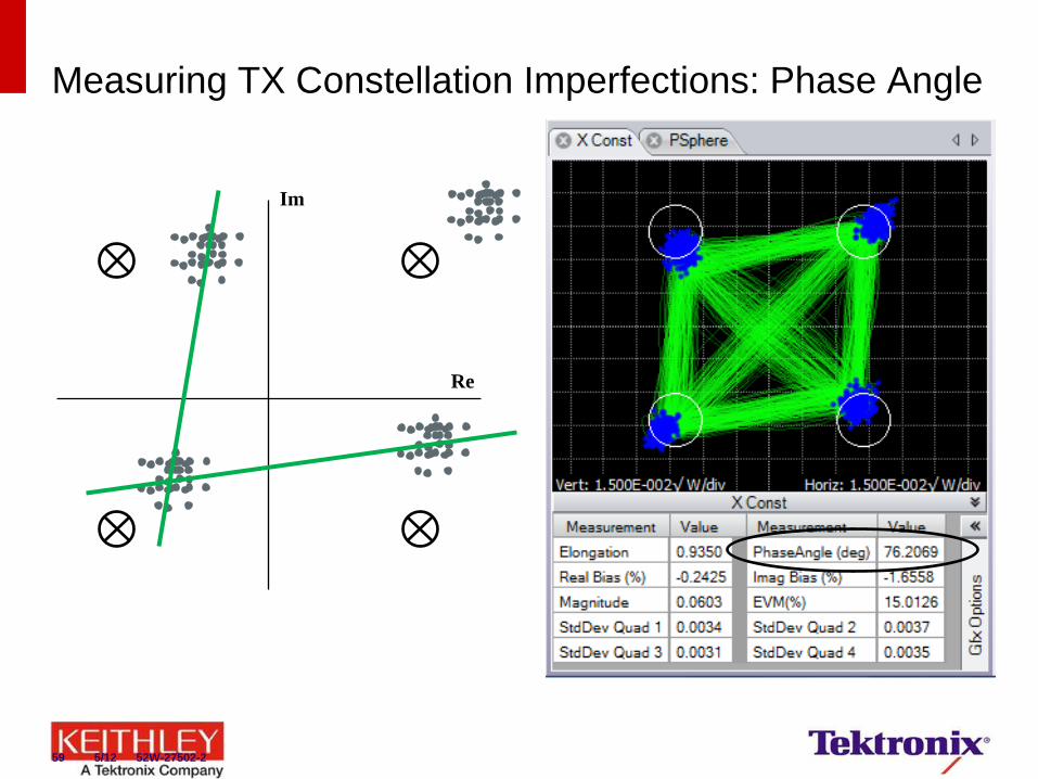
Measuring TX Constellation Imperfections: Phase Angle
Re
Im
59 5/12 52W-27502-2

Exclusive: Example: Adjusting Tributary Timing Skew
60 5/12 52W-27502-2
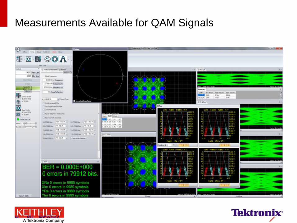
Measurements Available for QAM Signals
62 5/12 52W-27502-2
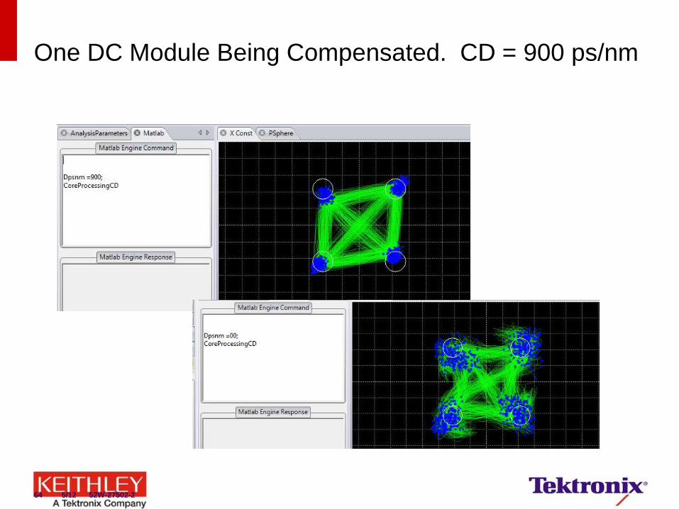
One DC Module Being Compensated. CD = 900 ps/nm
64 5/12 52W-27502-2
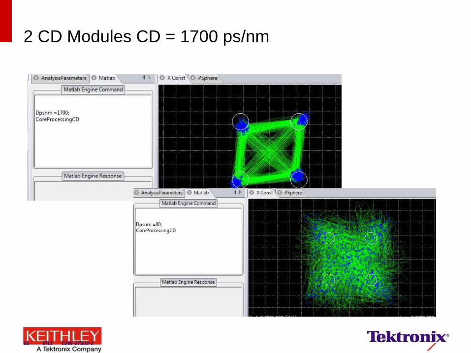
2 CD Modules CD = 1700 ps/nm
65 5/12 52W-27502-2
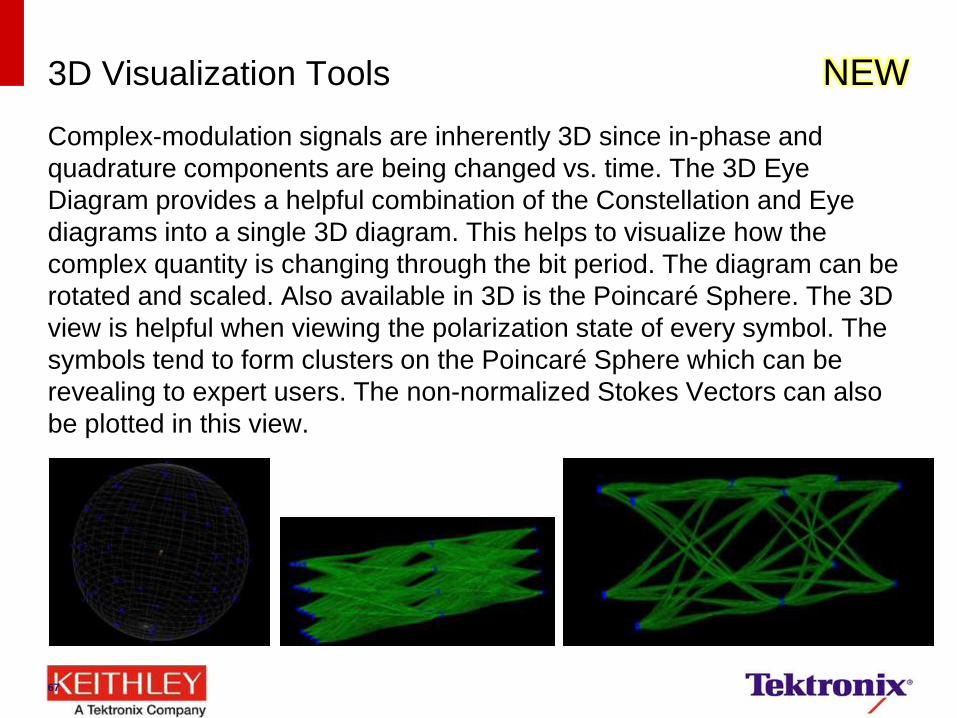
3D Visualization Tools NEW
Complex-modulation signals are inherently 3D since in-phase and
quadrature components are being changed vs. time. The 3D Eye
Diagram provides a helpful combination of the Constellation and Eye
diagrams into a single 3D diagram. This helps to visualize how the
complex quantity is changing through the bit period. The diagram can be
rotated and scaled. Also available in 3D is the Poincaré Sphere. The 3D
view is helpful when viewing the polarization state of every symbol. The
symbols tend to form clusters on the Poincaré Sphere which can be
revealing to expert users. The non-normalized Stokes Vectors can also
be plotted in this view.
67
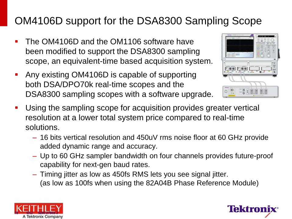
OM4106D support for the DSA8300 Sampling Scope
The OM4106D and the OM1106 software have
been modified to support the DSA8300 sampling
scope, an equivalent-time based acquisition system.
Any existing OM4106D is capable of supporting
both DSA/DPO70k real-time scopes and the
DSA8300 sampling scopes with a software upgrade.
Using the sampling scope for acquisition provides greater vertical
resolution at a lower total system price compared to real-time
solutions.
– 16 bits vertical resolution and 450uV rms noise floor at 60 GHz provide
added dynamic range and accuracy.
– Up to 60 GHz sampler bandwidth on four channels provides future-proof
capability for next-gen baud rates.
– Timing jitter as low as 450fs RMS lets you see signal jitter.
(as low as 100fs when using the 82A04B Phase Reference Module)
72 5/12 52W-27502-2

Example Equivalent Time Scope Configuration
DSA8300 w/ Qty 2, 80E09
OM4106D w/ Opt. EXT
Note: Ethernet connections not shown. All instruments assumed to be connected to same network.
76 5/12 52W-27502-2
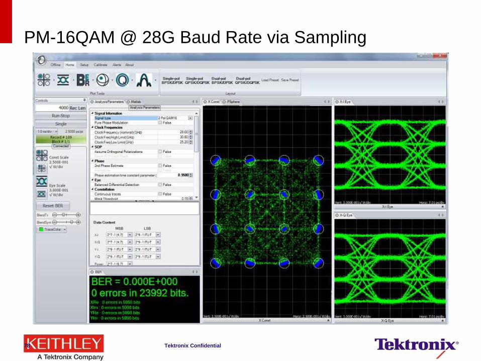
PM-16QAM @ 28G Baud Rate via Sampling
Tektronix Confidential 78
81
Customer Challenges for 400G
Even as 100G coherent optical systems are being deployed,
architecture for 400G systems and beyond are in development
Current proposals vary considerably from the number of carriers, to
the carrier spacing, to the modulation format used
The test and measurement system must have the flexibility to
support any combination of system parameters
81 3/2013 52W-27502-3
Example Industry Approaches to 400G and Beyond
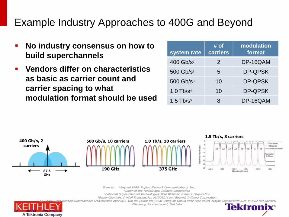
Sources: 1Beyond 100G, Fujitsu Network Communications, Inc. 2Dawn of the Terabit Age, Infinera Corporation
3Coherent Super-Channel Technologies, OSA Webinar, Infinera Corporation 4Super-Channels: DWDM Transmission at100Gb/s and Beyond, Infinera Corporation
51.5-Tb/s Guard-Banded Superchannel Transmission over 56× 100-km (5600-km) ULAF Using 30-Gbaud Pilot-Free OFDM-16QAM Signals with 5.75-b/s/Hz Net Spectral Efficiency, Alcatel-Lucent, Bell Labs
system rate
# of
carriers
modulation
format
400 Gb/s1 2 DP-16QAM
500 Gb/s2 5 DP-QPSK
500 Gb/s3 10 DP-QPSK
1.0 Tb/s4 10 DP-QPSK
1.5 Tb/s5 8 DP-16QAM
87.5 GHz
400 Gb/s, 2 carriers
190 GHz 375 GHz
500 Gb/s, 10 carriers 1.0 Tb/s, 10 carriers 1.5 Tb/s, 8 carriers
No industry consensus on how to
build superchannels
Vendors differ on characteristics
as basic as carrier count and
carrier spacing to what
modulation format should be used
82 3/2013 52W-27502-3
Tektronix Introduces Multi-Carrier Superchannel Support
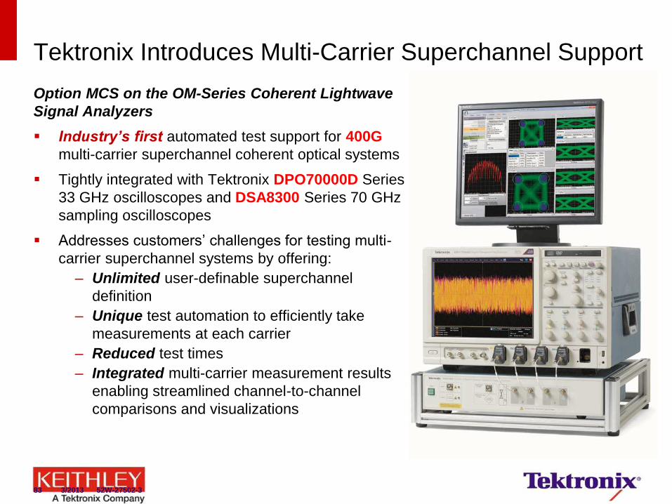
Option MCS on the OM-Series Coherent Lightwave
Signal Analyzers
Industry’s first automated test support for 400G
multi-carrier superchannel coherent optical systems
Tightly integrated with Tektronix DPO70000D Series
33 GHz oscilloscopes and DSA8300 Series 70 GHz
sampling oscilloscopes
Addresses customers’ challenges for testing multi-
carrier superchannel systems by offering:
– Unlimited user-definable superchannel
definition
– Unique test automation to efficiently take
measurements at each carrier
– Reduced test times
– Integrated multi-carrier measurement results
enabling streamlined channel-to-channel
comparisons and visualizations
83 3/2013 52W-27502-3
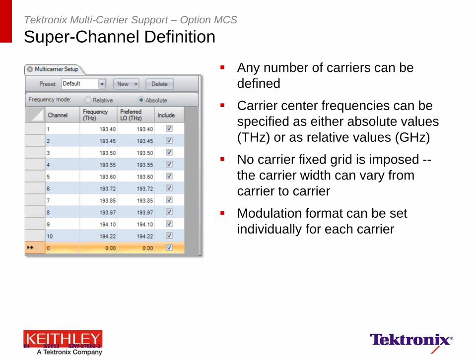
Tektronix Multi-Carrier Support – Option MCS
Super-Channel Definition
Any number of carriers can be
defined
Carrier center frequencies can be
specified as either absolute values
(THz) or as relative values (GHz)
No carrier fixed grid is imposed --
the carrier width can vary from
carrier to carrier
Modulation format can be set
individually for each carrier
84 3/2013 52W-27502-3
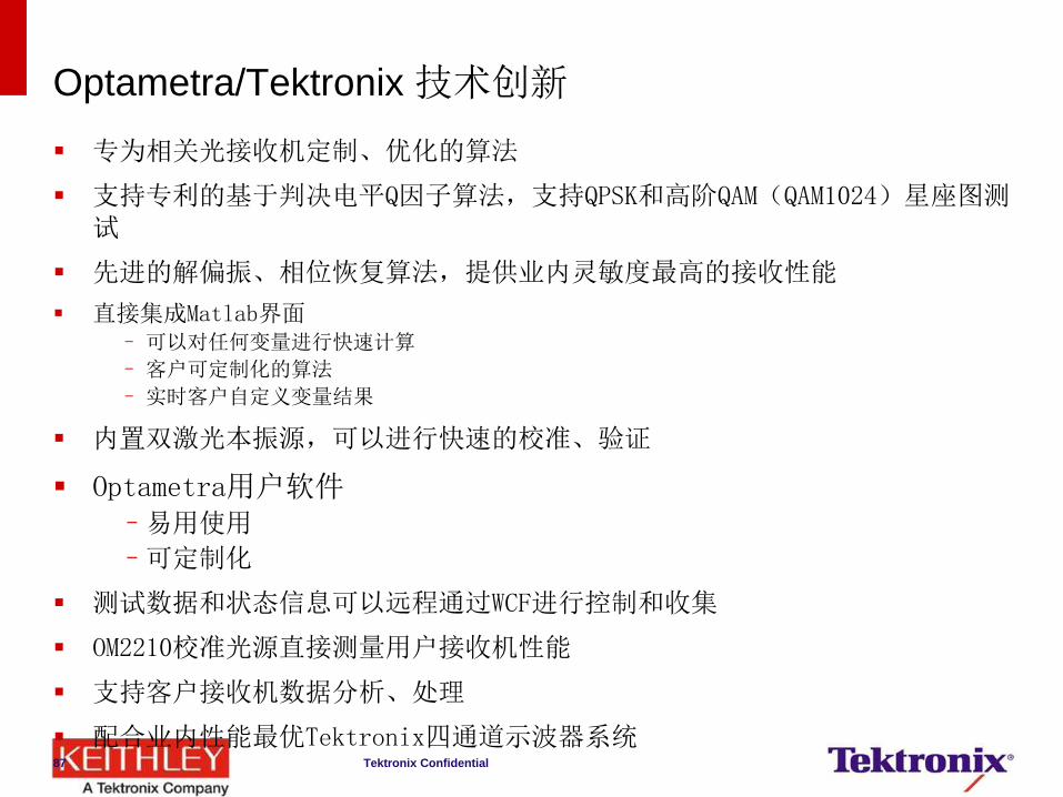
Optametra/Tektronix 技术创新
专为相关光接收机定制、优化的算法
支持专利的基于判决电平Q因子算法,支持QPSK和高阶QAM(QAM1024)星座图测试
先进的解偏振、相位恢复算法,提供业内灵敏度最高的接收性能
直接集成Matlab界面 – 可以对任何变量进行快速计算
– 客户可定制化的算法
– 实时客户自定义变量结果
内置双激光本振源,可以进行快速的校准、验证
Optametra用户软件 –易用使用
–可定制化
测试数据和状态信息可以远程通过WCF进行控制和收集
OM2210校准光源直接测量用户接收机性能
支持客户接收机数据分析、处理
配合业内性能最优Tektronix四通道示波器系统
Tektronix Confidential 87
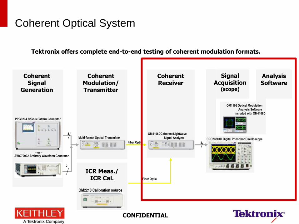
Analysis Software
Signal Acquisition
(scope)
Coherent Optical System
PPG3204 32Gb/s Pattern Generator
AWG70002 Arbitrary Waveform Generator
Multi-format Optical Transmitter OM4106DCoherent Lightwave
Signal Analyzer
4
2
Fiber Optic 4
– or –
DPO73304D Digital Phosphor Oscilloscope
Coherent Signal
Generation
Coherent Modulation/ Transmitter
Coherent Receiver
OM1106 Optical Modulation
Analysis Software
Included with OM4106D
Tektronix offers complete end-to-end testing of coherent modulation formats.
CONFIDENTIAL
ICR Meas./ ICR Cal.
Fiber Optic
OM2210 Calibration source
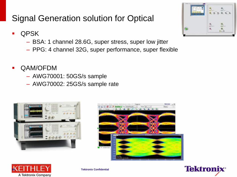
Signal Generation solution for Optical
QPSK
– BSA: 1 channel 28.6G, super stress, super low jitter
– PPG: 4 channel 32G, super performance, super flexible
QAM/OFDM
– AWG70001: 50GS/s sample
– AWG70002: 25GS/s sample rate
Tektronix Confidential 90
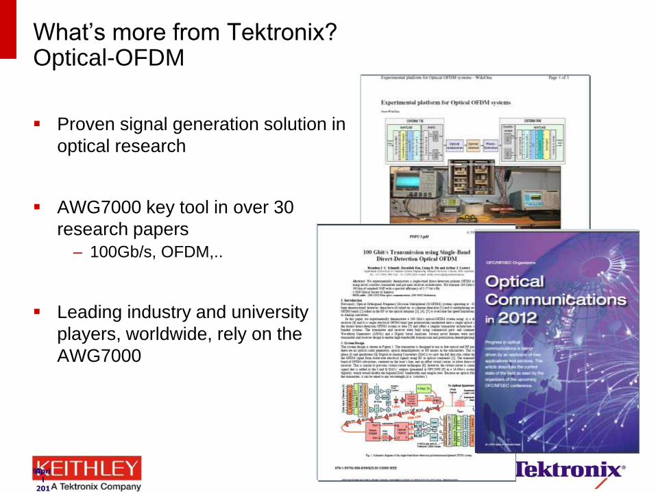
What’s more from Tektronix? Optical-OFDM
Proven signal generation solution in
optical research
AWG7000 key tool in over 30
research papers
– 100Gb/s, OFDM,..
Leading industry and university
players, worldwide, rely on the
AWG7000
April
2011
97
98
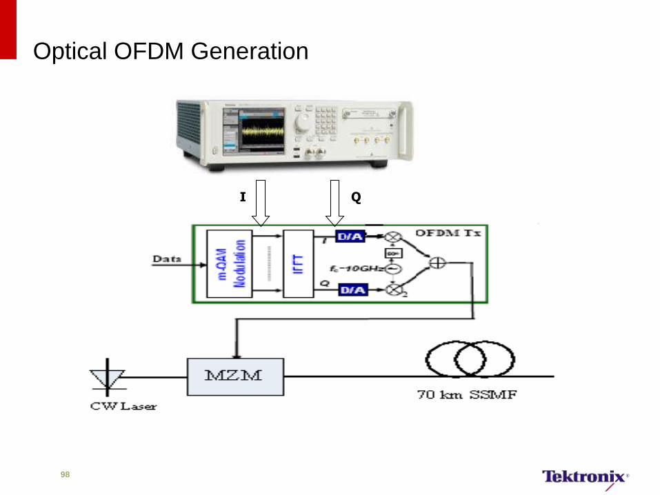
Optical OFDM Generation
I Q
99 12/2012 65W-28713-0
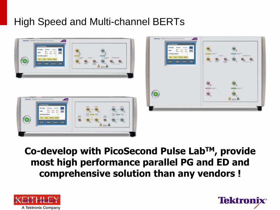
High Speed and Multi-channel BERTs
Co-develop with PicoSecond Pulse LabTM, provide most high performance parallel PG and ED and
comprehensive solution than any vendors !
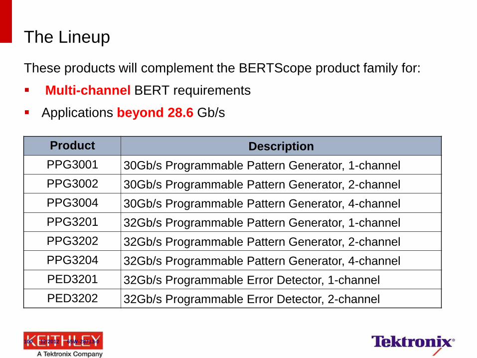
The Lineup
These products will complement the BERTScope product family for:
Multi-channel BERT requirements
Applications beyond 28.6 Gb/s
Product Description
PPG3001 30Gb/s Programmable Pattern Generator, 1-channel
PPG3002 30Gb/s Programmable Pattern Generator, 2-channel
PPG3004 30Gb/s Programmable Pattern Generator, 4-channel
PPG3201 32Gb/s Programmable Pattern Generator, 1-channel
PPG3202 32Gb/s Programmable Pattern Generator, 2-channel
PPG3204 32Gb/s Programmable Pattern Generator, 4-channel
PED3201 32Gb/s Programmable Error Detector, 1-channel
PED3202 32Gb/s Programmable Error Detector, 2-channel
100 12/2012 65W-28713-0
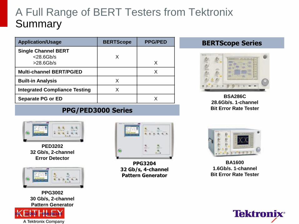
A Full Range of BERT Testers from Tektronix Summary
BSA286C
28.6Gb/s. 1-channel
Bit Error Rate Tester
BA1600
1.6Gb/s. 1-channel
Bit Error Rate Tester
BERTScope Series
PED3202
32 Gb/s, 2-channel
Error Detector
PPG3002
30 Gb/s, 2-channel
Pattern Generator
PPG3204 32 Gb/s, 4-channel Pattern Generator
PPG/PED3000 Series
Application/Usage BERTScope PPG/PED
Single Channel BERT
<28.6Gb/s
>28.6Gb/s
X
X
Multi-channel BERT/PG/ED X
Built-in Analysis X
Integrated Compliance Testing X
Separate PG or ED X
101 12/2012 65W-28713-0
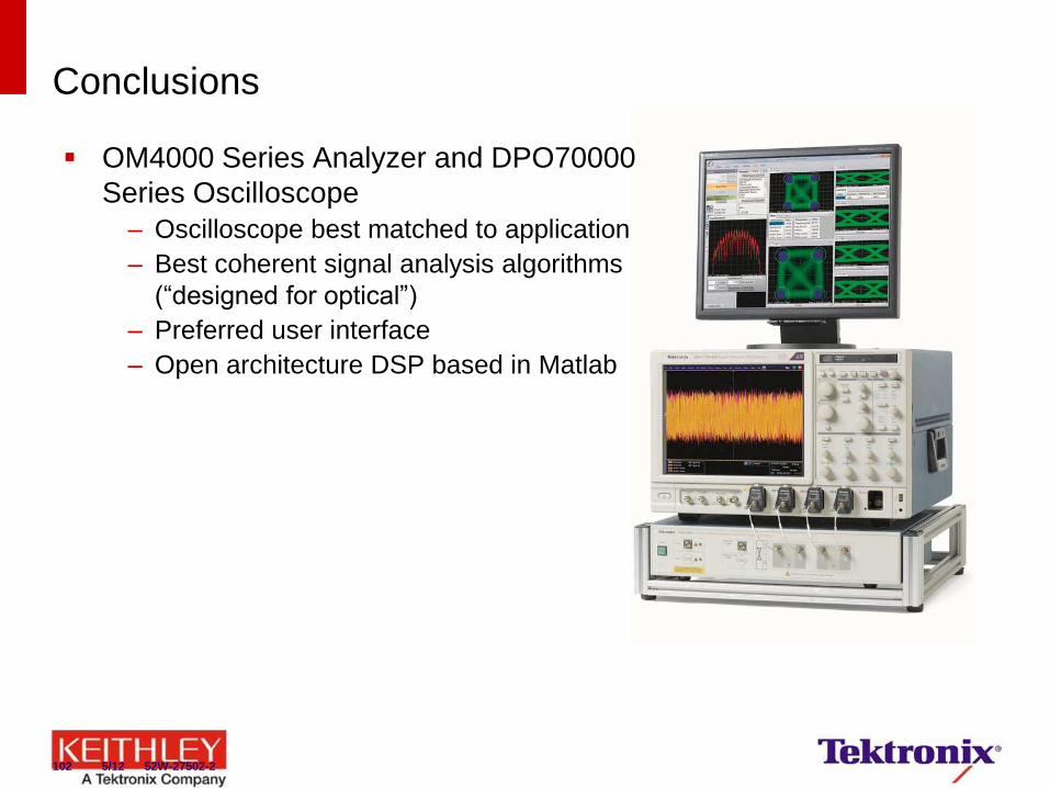
Conclusions
OM4000 Series Analyzer and DPO70000
Series Oscilloscope
– Oscilloscope best matched to application
– Best coherent signal analysis algorithms
(“designed for optical”)
– Preferred user interface
– Open architecture DSP based in Matlab
102 5/12 52W-27502-2

Thank You For Attending!